2005 NASA Executive Capability Roadmap Report
334
8/25/2005 Capability Roadmap Report Page 1 NASA Capability Roadmaps Executive Summary May 22, 2005
-
Upload
khangminh22 -
Category
Documents
-
view
1 -
download
0
Transcript of 2005 NASA Executive Capability Roadmap Report

8/25/2005 Capability Roadmap Report Page 1
NASA
Capability Roadmaps
Executive Summary
May 22, 2005
8/25/2005 Capability Roadmap Report Page 2
1 OVERVIEW .........................................................................................................................................................................7 1.1 INTRODUCTION AND BACKGROUND......................................................................................................................... 7 1.2 CONTEXT AND CONTENT OF THIS REPORT .............................................................................................................. 8 1.3 OVERVIEW OF CAPABILITY ROADMAP PRODUCTS.............................................................................................. 10
1.3.1 Summary Roadmaps of the Top Capabilities .................................................................................................10 1.3.2 Highest-Benefit Capability Technical Challenges ........................................................................................20 1.3.3 The Capability Roadmap Development Process............................................................................................21 1.3.4 Additional Sources of Information...................................................................................................................23 1.3.5 Individual Capability Roadmap Summaries...................................................................................................24 1.3.6 Conclusions..........................................................................................................................................................25
2 HIGH ENERGY POWER AND PROPULSION (ROADMAP 2) ......................................................................27 2.1 GENERAL CAPABILITY OVERVIEW......................................................................................................................... 27
2.1.1 Capability Description.......................................................................................................................................27 2.1.2 Benefits..................................................................................................................................................................27 2.1.3 Key Architecture / Strategic Decisions............................................................................................................27 2.1.4 Major Technical Challenges.............................................................................................................................28 2.1.5 Key Capabilities and Status..............................................................................................................................30
2.2 ROADMAP DEVELOPMENT ....................................................................................................................................... 32 2.2.1 Legacy Activities and Roadmap Assumptions................................................................................................32 2.2.2 Capability Breakdown Structure......................................................................................................................32 2.2.3 Roadmap Logic....................................................................................................................................................34 2.2.4 Capabilities Assessment.....................................................................................................................................39 2.2.5 Relationship to Other Roadmaps......................................................................................................................41 2.2.6 Infrastructure Assessment..................................................................................................................................42
2.3 SUMMARY .................................................................................................................................................................. 43 ACRONYM LIST .......................................................................................................................................................................... 44
3 IN-SPACE TRANSPORTATION (ROADMAP 3) .................................................................................................46 3.1 GENERAL CAPABILITY OVERVIEW......................................................................................................................... 46
3.1.1 Capability Description.......................................................................................................................................46 3.1.2 Benefits..................................................................................................................................................................46 3.1.3 Key Architecture / Strategic Decisions............................................................................................................47 3.1.4 Major Technical Challenges.............................................................................................................................49 3.1.5 Key Capabilities and Status..............................................................................................................................51
3.2 ROADMAP DEVELOPMENT ....................................................................................................................................... 53 3.2.1 Legacy Activities and Roadmap Assumptions................................................................................................53 3.2.2 Capability Breakdown Structure......................................................................................................................55 3.2.3 Roadmap Logic....................................................................................................................................................57 3.2.4 Capabilities Assessment.....................................................................................................................................62 3.2.5 Infrastructure Assessment..................................................................................................................................66
3.3 SUMMARY .................................................................................................................................................................. 67 ACRONYM LIST.......................................................................................................................................................................... 68
4 ADVANCED TELESCOPE AND OBSERVATORY (ROADMAP 4) ..............................................................71 4.1 GENERAL CAPABILITY OVERVIEW......................................................................................................................... 71
4.1.1 Capability Description.......................................................................................................................................71 4.1.2 Benefits..................................................................................................................................................................74 4.1.3 Key Architecture / Strategic Decisions............................................................................................................74 4.1.4 Major Technical Challenges.............................................................................................................................75 4.1.5 Key Capabilities and Status..............................................................................................................................76
4.2 ROADMAP DEVELOPMENT ....................................................................................................................................... 83 4.2.1 Legacy Activities and Roadmap Assumptions................................................................................................83

8/25/2005 Capability Roadmap Report Page 3
4.2.2 Capability Breakdown Structure......................................................................................................................84 4.2.3 Roadmap Logic....................................................................................................................................................86 4.2.4 Infrastructure Assessment..................................................................................................................................89
4.3 SUMMARY .................................................................................................................................................................. 91 ACRONYM LIST.......................................................................................................................................................................... 92
5 COMMUNICATION AND NAVIGATION CAPABILITY (ROADMAP 5) ..................................................94 5.1 GENERAL CAPABILITY OVERVIEW......................................................................................................................... 94
5.1.1 Capability Description.......................................................................................................................................94 5.1.2 Benefits..................................................................................................................................................................95 5.1.3 Major Technical Challenges.............................................................................................................................97 5.1.4 Key Capabilities..................................................................................................................................................99
5.2 ROADMAP DEVELOPMENT .....................................................................................................................................100 5.2.1 Legacy Activities and Key Assumptions....................................................................................................... 100 5.2.2 Capability Breakdown Structure Rationale................................................................................................. 103 5.2.3 Roadmap Logic................................................................................................................................................. 105 5.2.4 Capabilities Assessment.................................................................................................................................. 109 5.2.5 Relationship to Other Capability Roadmaps............................................................................................... 110 5.2.6 Infrastructure Assessment............................................................................................................................... 112
5.3 SUMMARY ................................................................................................................................................................114 ACRONYM LIST........................................................................................................................................................................115
6 ROBOTIC ACCESS TO PLANETARY SURFACES (ROADMAP 6).......................................................... 118 6.1 GENERAL CAPABILITY OVERVIEW.......................................................................................................................118
6.1.1 Capability Description.................................................................................................................................... 118 6.1.2 Benefits............................................................................................................................................................... 118 6.1.3 Key Architecture / Strategic Decisions......................................................................................................... 118
6.2 ROADMAP DEVELOPMENT .....................................................................................................................................119 6.2.1 Top Level Architectural Assumptions & Applications............................................................................... 119 6.2.2 Legacy Activities and Roadmap Assumptions............................................................................................. 120 6.2.3 Capability Breakdown Structure................................................................................................................... 120 6.2.4 Roadmap Logic................................................................................................................................................. 122 6.2.5 Roadmap Examples.......................................................................................................................................... 122 6.2.6 Near-Term Capability Developments........................................................................................................... 125 6.2.7 Capabilities Assessment.................................................................................................................................. 125 6.2.8 Relationship to Other Roadmaps................................................................................................................... 135 6.2.9 Infrastructure.................................................................................................................................................... 136
6.3 SUMMARY ................................................................................................................................................................139 ACRONYM LIST ........................................................................................................................................................................140
7 HUMAN PLANETARY LANDING SYSTEMS (ROADMAP 7) .................................................................... 142 7.1 GENERAL CAPABILITY OVERVIEW.......................................................................................................................142
7.1.1 Capability Description.................................................................................................................................... 142 7.1.2 Benefits............................................................................................................................................................... 142 7.1.3 Key Architecture / Strategic Decisions......................................................................................................... 143 7.1.4 Major Technical Challenges.......................................................................................................................... 145 7.1.5 Key Capabilities and Status........................................................................................................................... 147
7.2 ROADMAP DEVELOPMENT .....................................................................................................................................148 7.2.1 Legacy Activities and Roadmap Assumptions............................................................................................. 148 7.2.2 Capability Breakdown Structure................................................................................................................... 149 7.2.3 Roadmap Logic................................................................................................................................................. 151 7.2.4 Capabilities Assessment.................................................................................................................................. 154 7.2.5 Relationship to Other Roadmaps................................................................................................................... 155 7.2.6 Infrastructure Assessment............................................................................................................................... 156

8/25/2005 Capability Roadmap Report Page 4
7.3 SUMMARY ................................................................................................................................................................158 ACRONYM LIST ........................................................................................................................................................................159
8 HUMAN HEALTH AND SUPPORT SYSTEMS CAPABILITY (ROADMAP 8) ..................................... 162 8.1 GENERAL CAPABILITY OVERVIEW.......................................................................................................................162
8.1.1 Capability Description.................................................................................................................................... 162 8.1.2 Benefits............................................................................................................................................................... 162 8.1.3 Key Architecture / Strategic Decisions......................................................................................................... 163 8.1.4 Major Technical Challenges.......................................................................................................................... 164 8.1.5 Key Capabilities and Status........................................................................................................................... 167
8.2 ROADMAP DEVELOPMENT .....................................................................................................................................168 8.2.1 Legacy Activities and Roadmap Assumptions............................................................................................. 168 8.2.2 Top Level Architectural Assumptions & Applications Ethics................................................................... 168 8.2.3 Capability Breakdown Structure................................................................................................................... 169 8.2.4 Roadmap Logic................................................................................................................................................. 171 8.2.5 Capabilities Assessment.................................................................................................................................. 175 8.2.6 Relationship to Other Roadmaps (capability and strategic) .................................................................... 177
8.3 SUMMARY ................................................................................................................................................................181 9 HUMAN EXPLORATION SYSTEMS AND MOBILITY (ROADMAP 9).................................................. 183
9.1 GENERAL CAPABILITY OVERVIEW.......................................................................................................................183 9.1.1 Capability Description.................................................................................................................................... 183 9.1.2 Benefits............................................................................................................................................................... 183 9.1.3 Key Architecture / Strategic Decisions......................................................................................................... 184 9.1.4 Major Technical Challenges.......................................................................................................................... 184 9.1.5 Key Capabilities and Status........................................................................................................................... 185 9.1.6 Key Capabilities and Status........................................................................................................................... 188
9.2 ROADMAP DEVELOPMENT .....................................................................................................................................191 9.2.1 Legacy Activities and Roadmap Assumptions............................................................................................. 191 9.2.2 Roadmap Logic................................................................................................................................................. 193 9.2.3 Relationship to Other Roadmaps (capability and strategic) .................................................................... 196
ACRONYM LIST ........................................................................................................................................................................196 10 AUTONOMOUS SYSTEMS, ROBOTICS, AND COMPUTING SYSTEMS (ROADMAP 10)............. 198
10.1 GENERAL CAPABILITY OVERVIEW.......................................................................................................................198 10.1.1 Capability Description............................................................................................................................... 198 10.1.2 Benefits ......................................................................................................................................................... 198 10.1.3 Key Architecture / Strategic Decisions................................................................................................... 198 10.1.4 Major Technical Challenges..................................................................................................................... 200 10.1.5 Key Capabilities and Status...................................................................................................................... 204
10.2 ROADMAP DEVELOPMENT .....................................................................................................................................206 10.2.1 Legacy Activities and Roadmap Assumptions........................................................................................ 206 10.2.2 Capability Breakdown Structure.............................................................................................................. 206 10.2.3 Roadmap Logic ........................................................................................................................................... 209 10.2.4 Capabilities Assessment............................................................................................................................. 214 10.2.5 Relationship to Other Roadmaps (capability and strategic)............................................................... 216
10.3 SUMMARY ................................................................................................................................................................216 11 TRANSFORMATIONAL SPACEPORT AND RANGE.................................................................................... 219
11.1 GENERAL CAPABILITY OVERVIEW.......................................................................................................................219 11.1.1 CAPABILITY DESCRIPTION .................................................................................................................. 219
11.2 ROADMAP DEVELOPMENT .....................................................................................................................................224 11.2.1 REFERENCE RELEVANT LEGACY ACTIVITIES............................................................................... 224 11.2.2 TOP-LEVEL ARCHITECTURAL ASSUMPTIONS ANDAPPLICATIONS ...................................... 224
8/25/2005 Capability Roadmap Report Page 5
11.2.3 RELATIONSHIP TO OTHER CAPABILITY ROADMAPS ................................................................. 227 11.3 SUMMARY ................................................................................................................................................................227 APPENDIX A: CAPABILITIES BREAKDOWN STRUCTURE (CBS) .......................................................................................230 APPENDIX B: TOP LEVEL CAPABILITY ROADMAP ROLLUP (2005-2015).......................................................................231
12 SCIENCE INSTRUMENTS AND SENSORS (ROADMAP 12)....................................................................... 233 12.1 GENERAL CAPABILITY OVERVIEW.......................................................................................................................233
12.1.1 Capability Description............................................................................................................................... 233 12.1.2 Benefits ......................................................................................................................................................... 233 12.1.3 Key Architecture / Strategic Decisions................................................................................................... 234 12.1.4 Major Technical Challenges..................................................................................................................... 236 12.1.5 Key Capabilities and Status...................................................................................................................... 238
12.2 ROADMAP DEVELOPMENT .....................................................................................................................................240 12.2.1 Legacy Activities and Roadmap Assumptions........................................................................................ 240 12.2.2 Capability Breakdown Structure.............................................................................................................. 244 12.2.3 Roadmap Logic ........................................................................................................................................... 247 12.2.4 Capabilities Assessment............................................................................................................................. 250 12.2.5 Relationship to Other Roadmaps (capability and strategic)............................................................... 257 12.2.6 Critical Facility Assessment...................................................................................................................... 258
12.3 SUMMARY ................................................................................................................................................................260 13 IN-SITU RESOURCE UTILIZATION (ROADMAP 13) .................................................................................. 265
13.1 GENERAL CAPABILITY OVERVIEW.......................................................................................................................265 13.1.1 Capability Description............................................................................................................................... 265 13.1.2 Benefits ......................................................................................................................................................... 266 13.1.3 Key Architecture / Strategic Decisions................................................................................................... 267 13.1.4 Major Technical Challenges..................................................................................................................... 269 13.1.5 Key Capabilities and Status...................................................................................................................... 270
13.2 ROADMAP DEVELOPMENT .....................................................................................................................................273 13.2.1 Legacy Activities and Roadmap Assumptions........................................................................................ 273 13.2.2 Reference Relevant Legacy Activities...................................................................................................... 273 13.2.3 Architectural Assumptions........................................................................................................................ 273 13.2.4 Capability Breakdown Structure.............................................................................................................. 277 13.2.5 Roadmap Logic........................................................................................................................................... 279 13.2.6 Capabilities Assessment............................................................................................................................. 282 13.2.7 Relationship to Other Roadmaps (capability and strategic)............................................................... 284 13.2.8 Infrastructure Assessment ......................................................................................................................... 285
REFERENCES ............................................................................................................................................................................289 14 ADVANCED MODELING, S IMULATION, AND ANALYSIS (ROADMAP 14)...................................... 293
14.1 GENERAL CAPABILITY OVERVIEW.......................................................................................................................293 14.1.1 Capability Description............................................................................................................................... 293 14.1.2 Capability Benefits ..................................................................................................................................... 293 14.1.3 Key Architecture / Strategic Decisions................................................................................................... 294 14.1.4 Key Capabilities and Status...................................................................................................................... 295 14.1.5 Key Capabilities.......................................................................................................................................... 296 14.1.6 Legacy Activities and Roadmap Assumptions........................................................................................ 299 14.1.7 Reference Relevant Legacy Activities...................................................................................................... 299 14.1.8 Top-Level Architectural Assumptions & Applications......................................................................... 299 14.1.9 Capability Breakdown Structure.............................................................................................................. 299 14.1.10 Roadmap Logic ........................................................................................................................................... 301 14.1.11 Relationship to Other Roadmaps............................................................................................................. 304
14.2 SUMMARY ................................................................................................................................................................304 ACRONYM LIST ........................................................................................................................................................................305
8/25/2005 Capability Roadmap Report Page 6
APPENDIX A: PAPERS AND ANALYSES REFERENCED BY THE ASMA TEAM .................................................................306 APPENDIX B: PRESENTATIONS TO ASMA TEAM ...............................................................................................................307
15 SYSTEMS ENGINEERING COST/RISK ANALYSIS ROADMAP (15) TAKE-AWAY........................ 310 15.1 GENERAL CAPABILITY OVERVIEW.......................................................................................................................310
15.1.1 Objective Description................................................................................................................................. 310 15.1.2 Capability Description............................................................................................................................... 310 15.1.3 Benefits ......................................................................................................................................................... 311 15.1.4 Major Technical Challenges..................................................................................................................... 311
ACRONYMS...............................................................................................................................................................................313 16 NANOTECHNOLOGY CAPAB ILITY ROADMAP (ROADMAP 16) ......................................................... 315
16.1 GENERAL CAPABILITY OVERVIEW.......................................................................................................................315 16.1.1 Capability Description............................................................................................................................... 315 16.1.2 Benefits ......................................................................................................................................................... 315 16.1.3 Specific Example of Capability Benefits for Exploration Systems:.................................................... 317 16.1.4 Key Architecture / Strategic Decisions................................................................................................... 317 16.1.5 Major Technical Challenges..................................................................................................................... 318 16.1.6 Key Capabilities.......................................................................................................................................... 318 16.1.7 Legacy Activities and Roadmap Assumptions........................................................................................ 320 16.1.8 Top Level Architectural Assumptions and Applications...................................................................... 321 16.1.9 Capability Breakdown Structure.............................................................................................................. 321 16.1.10 Roadmap Logic........................................................................................................................................... 323 16.1.11 Relationship to Other Roadmaps (capability and strategic)............................................................... 330 16.1.12 Infrastructure............................................................................................................................................... 331
16.2 ACRONYM LIST ........................................................................................................................................................332 APPENDIX A.............................................................................................................................................................................333
8/25/2005 Capability Roadmap Report Page 7
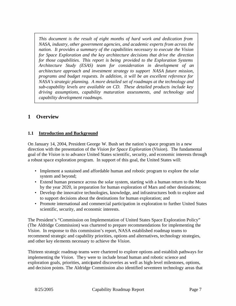
This document is the result of eight months of hard work and dedication from NASA, industry, other government agencies, and academic experts from across the nation. It provides a summary of the capabilities necessary to execute the Vision for Space Exploration and the key architecture decisions that drive the direction for those capabilities. This report is being provided to the Exploration Systems Architecture Study (ESAS) team for consideration in development of an architecture approach and investment strategy to support NASA future mission, programs and budget requests. In addition, it will be an excellent reference for NASA’s strategic planning. A more detailed set of roadmaps at the technology and sub-capability levels are available on CD. These detailed products include key driving assumptions, capability maturation assessments, and technology and capability development roadmaps.
1 Overview 1.1 Introduction and Background On January 14, 2004, President George W. Bush set the nation’s space program in a new direction with the presentation of the Vision for Space Exploration (Vision). The fundamental goal of the Vision is to advance United States scientific, security, and economic interests through a robust space exploration program. In support of this goal, the United States will:
• Implement a sustained and affordable human and robotic program to explore the solar system and beyond;
• Extend human presence across the solar system, starting with a human return to the Moon by the year 2020, in preparation for human exploration of Mars and other destinations;
• Develop the innovative technologies, knowledge, and infrastructures both to explore and to support decisions about the destinations for human exploration; and
• Promote international and commercial participation in exploration to further United States scientific, security, and economic interests.
The President’s “Commission on Implementation of United States Space Exploration Policy” (The Aldridge Commission) was chartered to prepare recommendations for implementing the Vision. In response to this commission’s report, NASA established roadmap teams to recommend strategic and capability priorities, options and alternatives, technology strategies, and other key elements necessary to achieve the Vision. Thirteen strategic roadmap teams were chartered to explore options and establish pathways for implementing the Vision. They were to include broad human and robotic science and exploration goals, priorities, anticipated discoveries as well as high- level milestones, options, and decision points. The Aldridge Commission also identified seventeen technology areas that

8/25/2005 Capability Roadmap Report Page 8
are critical to attaining the President’s exploration objectives within schedule and at affordable costs. The committee recommended that NASA form special project teams for each of the seventeen technology areas to develop roadmaps that lead to mature technologies. In October 2004, NASA’s Advanced Planning and Integration Office (APIO) commissioned fifteen capability roadmap teams to provide the necessary insight into the types of technology and capability investments that the Agency needs to make in order to achieve NASA’s highest priorities. These fifteen roadmaps resulted from combining some of the seventeen areas from the Commission’s report and adding technology areas that NASA management deemed critical for the Vision. The fifteen capability roadmaps are:
• High Energy Power and Propulsion • In-Space Transportation • Advanced Telescopes and Observatories • Communication and Navigation • Robotic Access to Planetary Surfaces • Human Planetary Landing Systems • Human Health and Support Systems • Human Exploration Systems and Mobility • Autonomous System Robotics and Computing • Transformational Spaceport and Range • Scientific Instruments and Sensors • In-Situ Resource Utilization • Advanced Modeling and Simulation • System Engineering Cost Risk Analysis • Nanotechnology
1.2 Context and Content of this Report The capability roadmaps were scheduled to be delivered in September 2005. In early May 2005, near-term Vision goals were significantly accelerated in order to impact the FY 05 Operating Plan, the FY 06 Budget Plan, and the FY 07 Budget Development. Given this decision to accelerate the schedule, the Agency determined that all roadmap efforts – both strategic and capability – would be completed by May 22, 2005. The May 22nd reports are intended to provide timely inputs to the architecture study teams established by NASA Administrator, Dr. Michael Griffin. The capability roadmapping teams referred to a common set of missions (shown in Figures 1.1a and 1.1b) in order to maintain internal consistency. However, the teams recognized that the architecture ultimately chosen for implementing the Vision might contain missions and decision dates that differ from those currently referenced. Therefore the teams considered additional
8/25/2005 Capability Roadmap Report Page 9
missions as viable alternatives for NASA as it evolves its programs in response to future discoveries, findings, and technical and programmatic challenges. Thus, the set of capabilities identified is intrinsically robust and can accommodate program evolution. The roadmap timelines described – based on expected development times – can be adjusted to conform to the overall schedule that will develop as the Vision is implemented. This report consists of:
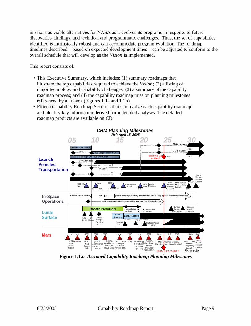
• This Executive Summary, which includes: (1) summary roadmaps that illustrate the top capabilities required to achieve the Vision; (2) a listing of major technology and capability challenges; (3) a summary of the capability roadmap process; and (4) the capability roadmap mission planning milestones referenced by all teams (Figures 1.1a and 1.1b).
• Fifteen Capability Roadmap Sections that summarize each capability roadmap and identify key information derived from detailed analyses. The detailed roadmap products are available on CD.
Mars
05 10 15 20 25 30
2008 CEVDemo
Un-Crewed CEV
Mars HumanMission Launch
(MSL1) Mars
Science Lab
(MSL2) Mars Science Lab, MTO1,
Scout
(MSR) Mars Sample
Return & Orbiter /ERV
LaunchVehicles,Transportation
LunarSurface
Mars
Ready to Go to Mars?
20142011
2025
2013
2009 2011 2016 203X2022
Robotic Precursors
LRO 2008
Landing Sites(s) Decision
2012
2nd
Mission
Lunar SortiesLEODemos
MarsSingle Location Outpost
Outpost Site Chosen
Human Lunar Landings
Extend. Location Outpost or Global
Mars
(MSHP) Mars Scaled
HumanPrecursor
(EDL, ISRU)
Robotic Missions
Phoenix
2007
(MRO) Mars
Recon Orbiter
2005 2013
(MHP1)Mars Human
Precursor (H2O), Scout
TBD
2018 2020
Astrobiology Foundation Lab (Solar Sys Div.)
2024 2026
Mars Dynamics Mission, Mars Aeronomy (Solar Sys. Div)
Mars HumanMission
Cargo Only Launch
2031+
CRM Planning Milestones
Crewed CEV
Long Duration Lunar Missions
Mars Human Mission Cargo Launch
203X
Mars HumanMission Launch
Figure 1aReady to go to Mars?
2029
In Space Lunar Cargo Vehicle/Ascent/Descent
Mars Cargo
Moon/Mars Cargo/Prometheus Launch Vehicle
Mars Crew
Crewed Launch Vehicle & In -Space Moon/MarsUncrewed
Foreign LVs – ISS Crew/Cargo
ISS Cargo/Research LV
Shuttle – ISS Assembly
Until Lunar Outpost exists
ETO & in-Space
In Space
ETO
ETO & In Space
ETO & in-Space
Robotic/Uncrewed Transportation Systems – Science, Lunar/Mars Robotics
PrometheusLaunch
203X
203XETO
In-SpaceOperations
ISS Ops
Human Health & Performance / Bio Astronautics Risk Reduction
Space Servicing/Assembly (telerobotics, EVA): Large optics, crewed Mars missions
Mars HumanMission
Assembly
Shuttle – ISS Assembly
2031+2020
NavCom2017
Surface Power(~30kw)
SurfacePower
(50-100kw)
SurfaceMobility(100 km)
Surface Mobility (10s of km)
Ref: April 15, 2005
Figure 1.1a: Assumed Capability Roadmap Planning Milestones

8/25/2005 Capability Roadmap Report Page 10
Universe
Solar System
JWST
2011
SIM
2012
TPF-C
2016
CON-X
2017
TPF-I
2019 20NN 20NN 20NN 20NN 20NN
LISA
2014
2020
New Frontiers 4
2015
Trop Wind Lidar
2013
New Frontiers 2
2016
New Frontiers 3
2023
New Frontiers 5
2011
RBSP
Sequence of competitive selections: lunar sample, comet sample, Venus, Jupiter . . .
2026
New Frontiers 6
JDEM
05 10 15 20 25 30
Earth-Sun
Solar Probe
2018
2023
Stellar Imager
20302013
MMS SPIor SWB
2026
IS Probe
2028
Ready to Go to Mars?
Europa mission
Titan, Venus mission
Europa Lander or Advanced Titan
Figure 1b
LEGEND
Cross Cutting Decision
Strategic Road Map Decision
Milestone / Event
Range of Possible Dates
FOR NASA CRM PLANNING PURPOSES ONLY
Sequence of large/complex optical systems[SAFIR, Inflation Probe, LUVO, BHF, FIRSI, BBO, BHI, Life Finder, Planet Imager, . . .]
GEC
2016
L1 Diamond,Heliostorm
Mag Con,Dayside Con
2021Constellation or solar sail missions
Sun-Earth Science
Earth Science & Applications
2010
GPM
2013
Global Atm Comp
GEO Coastal CarbonGEO Air Quality
2019 2022
GEO LidarSounder
2025
GEO Water CycleGEO Surface Deformation
GEO Water Quality
2028
2018
Integrated Distributed SystemsLarge Apertures & Detectors
2015
Sentinels
Active Sensing
Sequence of Explorer missions ….
Neptune Orbiter or Comet Nucleus or
Venus Sample
CRM Planning MilestonesRef: April 15, 2005
Figure 1.1b: Assumed Capability Roadmap Planning Milestones
1.3 Overview of Capability Roadmap Products This section presents a summary of the products from all fifteen capability roadmaps. Included is a graphic representation of the top capabilities as they relate to planning milestones. In addition, this section tabulates the technical challenges that were identified as “highest benefit” by the fifteen roadmap teams. 1.3.1 Summary Roadmaps of the Top Capabilities Figures 1.2 through 1.6 are a graphic representation of the most important capabilities identified by each capability roadmap team as they relate to strategic milestones in five areas of focus (Transportation, In-space Operations, Lunar, Mars, and Science). A blue triangle indicates the required Initial Operations Capability date as driven by planning milestones, while the green bar represents the estimated development time required to mature the capability to flight-ready status. This representation does not capture the relationships and interdependencies among capabilities. These greatly affect the timing of key decisions and the final structure of any eventual exploration architecture. For example, the ascent/descent propulsion capability for Human Mars Exploration has a significant mass impact that will affect the performance required of in-space
8/25/2005 Capability Roadmap Report Page 11
transfer stages and Earth-to-Orbit launch vehicles as well as the number of on orbit assembly operations, etc. While the timeline shows development of this capability beginning approximately 2026, its architectural- level impact should be analyzed and characterized early in the process of defining a Mars human exploration architecture. This example is just one thread of a very complex web of relationships and interdependencies that comprise the scope of a vast decision space.

8/25/2005 Capability Roadmap Report Page 12
High Power Energy and Propulsion
CRM 05 10 15 20 25 30
Launch Vehicles and Transportation Planning Milestones and Key Capabilities
2008 CEVDemo
Un-Crewed CEV
Ready to Go to Mars?
20142011
2025
Crewed CEV
Long Duration Lunar
Missions 2020 ~2030+
Mars HumanMission Launch
In Space Lunar Cargo Vehicle/Ascent/Descent
Mars Cargo
Moon/Mars Cargo/Prometheus Launch Vehicle
Mars Crew
Crewed Launch Vehicle & In-Space Moon/MarsUncrewed
Foreign LVs – ISS Crew/Cargo
ISS Cargo/Research LV
Until Lunar Outpost exist.
ETO & in-Space
In Space
ETO
ETO & In Space
ETO & in-Space
Robotic/Uncrewed Transportation Systems – Science, Lunar/Mars Robotics
Prometheus Flight
203X
203XETO
Mars HumanMission
Assembly
Shuttle – ISS Assembly
Nuclear Fission Power (In-Space)Nuclear Fission Power (In-Space)
Human Rated Upper Stage Engine
Human Rated Upper Stage Engine
InSpaceTransportation
Advanced Modeling, Simulation and Analysis
Advance Science ModelingAdvance Science Modeling
Advance Operations ModelingAdvance Operations Modeling
Advance Engineering ModelingAdvance Engineering Modeling
Common Life Cycle Cost ModelsCommon Life Cycle Cost Models
Risk Mitigation Analysis Capability
Risk Mitigation Analysis Capability
Integrated SE/LCC/Risk/Safety AnalysisIntegrated SE/LCC/Risk/Safety Analysis
Agency-wide Predictive Safety Analysis Agency-wide Predictive Safety Analysis
Systems Engineering, Risk and Cost Analysis
Figure 1.2a - Key Transportation Capabilities
CRM 05 10 15 20 25 3005 10 15 20 25 30
Launch Vehicles and Transportation Planning Milestones and Key Capabilities
2008 CEVDemo
Un-Crewed CEV
Ready to Go to Mars?
20142011
2025
Crewed CEV
Long Duration Lunar
Missions 2020 ~2030+
Mars HumanMission Launch
In Space Lunar Cargo Vehicle/Ascent/Descent
Mars Cargo
Moon/Mars Cargo/Prometheus Launch Vehicle
Mars Crew
Crewed Launch Vehicle & In-Space Moon/MarsUncrewed
Foreign LVs – ISS Crew/Cargo
ISS Cargo/Research LV
Until Lunar Outpost exist.
ETO & in-Space
In Space
ETO
ETO & In Space
ETO & in-Space
Robotic/Uncrewed Transportation Systems – Science, Lunar/Mars Robotics
Prometheus Flight
203X
203XETO
Mars HumanMission
Assembly
Shuttle – ISS Assembly
2008 CEVDemo
Un-Crewed CEV
Ready to Go to Mars?
20142011
2025
Crewed CEV
Long Duration Lunar
Missions 2020 ~2030+
Mars HumanMission Launch
In Space Lunar Cargo Vehicle/Ascent/Descent
Mars Cargo
Moon/Mars Cargo/Prometheus Launch Vehicle
Mars Crew
Crewed Launch Vehicle & In-Space Moon/MarsUncrewed
Foreign LVs – ISS Crew/Cargo
ISS Cargo/Research LV
Until Lunar Outpost exist.
ETO & in-Space
In Space
ETO
ETO & In Space
ETO & in-Space
Robotic/Uncrewed Transportation Systems – Science, Lunar/Mars Robotics
Prometheus Flight
203X
203XETO
Mars HumanMission
Assembly
Shuttle – ISS Assembly
Nanotechnology
Reduce Structural Weight by 3x, Application Specific Multifunctional Materials, Thermal ManagementReduce Structural Weight by 3x, Application Specific Multifunctional Materials, Thermal Management
Reconfigurable Fault Tolerant Electronics, Microcraft, High Efficiency Power Systems, IVHMReconfigurable Fault Tolerant Electronics, Microcraft, High Efficiency Power Systems, IVHM
Lightweight TPS (25% lighter)Lightweight TPS (25% lighter)
30% Lighter Cryotanks30% Lighter Cryotanks
50% lighter TPS with Radiation Protection50% lighter TPS with Radiation Protection
Autonomous Root Cause AnalysisAutonomous Root Cause Analysis
Autonomous Systems, Robotics and Computing Decision Support for Mission SupportDecision Support for Mission Support
Autonomous Rendezvous & DockingAutonomous Rendezvous & Docking
Figure 1.2b - Key Transportation Capabilities

8/25/2005 Capability Roadmap Report Page 13
05 10 15 20 25 3005 10 15 20 25 30In-Space Operations Planning Milestones & Key Capabilities
CRM Shuttle – ISS Assembly ISS Ops
Human Health/Bioastronautics Critical Path Risk Reduction
Space Servicing/Assembly (telerobotics, EVA): Large optics, crewed Mars missionsShuttle – ISS Assembly ISS Ops
Human Health/Bioastronautics Critical Path Risk Reduction
Space Servicing/Assembly (telerobotics, EVA): Large optics, crewed Mars missions
Human Health and Support Systems
•InSpace EVA System•InSpace EVA System
Cryo StorageCryo Storage
Autonomous Rendezvous & DockingAutonomous Rendezvous & Docking
Auto Vehicle Health & Mission MgmtAuto Vehicle Health & Mission Mgmt
Common Arch Element InterfacesCommon Arch Element Interfaces
InSpaceTransportation
Advanced Modeling, Simulation and Analysis
Advance Science ModelingAdvance Science Modeling
Advance Operations ModelingAdvance Operations Modeling
Advance Engineering ModelingAdvance Engineering Modeling
Common Life Cycle Cost ModelsCommon Life Cycle Cost Models
Risk Mitigation Analysis Capability
Risk Mitigation Analysis Capability
Integrated SE/LCC/Risk/Safety AnalysisIntegrated SE/LCC/Risk/Safety Analysis
Agency-wide Predictive Safety Analysis Agency-wide Predictive Safety Analysis
Systems Engineering, Risk and Cost Analysis
Assembly, Deployment & ServicingAssembly, Deployment & Servicing
Human Exploration Systems and Mobility
Autonomous Root Cause AnalysisAutonomous Root Cause Analysis
Autonomous Systems, Robotics and Computing
Robotic In -space AssemblyRobotic In -space Assembly
Robotic In-Space Servicing & MaintenanceRobotic In-Space Servicing & Maintenance
Autonomous Rendezvous & DockingAutonomous Rendezvous & Docking
Figure 1.3a - Key In-Space Operations Capabilities
Lunar Planning Milestones and Key Capabilities
Radioisotope PowerRadioisotope Power
Human Rated Upper Stage Engine
Human Rated Upper Stage Engine
Ascent/Descent PropAscent/Descent Prop
Aerocapture (Human Return)Aerocapture (Human Return)
Cryo StorageCryo Storage
Autonomous Rendezvous & DockingAutonomous Rendezvous & Docking
Auto Vehicle Health & Mission MgmtAuto Vehicle Health & Mission Mgmt
Common Arch Element InterfacesCommon Arch Element Interfaces
Lunar Relay NetworkLunar Relay Network
Solar Electric Propulsion (Lunar)Solar Electric Propulsion (Lunar)
Terminal Descent Systems (Moon)Terminal Descent Systems (Moon)
Lunar/Mars Site CharacterizationLunar/Mars Site Characterization
High Energy Power and Propulsion
InSpaceTransportation
Communication and Navigation
Robotic Access to Planetary Surfaces
Nuclear Fission Power (Surface)Nuclear Fission Power (Surface)
Robotic RoversRobotic Rovers
Propulsive DeceleratorsPropulsive Decelerators
Human Planetary Landing Systems
CRM05 10 15 20 25 30
2013Robotic Precursors
LRO 2008
Landing Sites(s)
Decision 2012
2nd
Mission
NavCom2017
SurfaceMobility
(10s of km)
SurfacePower
(~30kw)
SurfacePower
(50-100kw)
Lunar SortiesLEO
DemosMarsSingle Location Outpost
Outpost Site ChosenHuman Lunar Landing
Extend. Location Outpost or Global
Mars
SurfaceMobility
(100 km)
05 10 15 20 25 302013Robotic Precursors
LRO 2008
Landing Sites(s)
Decision 2012
2nd
Mission
NavCom2017
SurfaceMobility
(10s of km)
SurfacePower
(~30kw)
SurfacePower
(50-100kw)
Lunar SortiesLEO
DemosMarsSingle Location Outpost
Outpost Site ChosenHuman Lunar Landing
Extend. Location Outpost or Global
Mars
SurfaceMobility
(100 km)
NavCom2017
SurfaceMobility
(10s of km)
SurfacePower
(~30kw)
SurfacePower
(50-100kw)
Lunar SortiesLEO
DemosMarsSingle Location Outpost
Outpost Site ChosenHuman Lunar Landing
Extend. Location Outpost or Global
Mars
SurfaceMobility
(100 km)
NavCom2017
NavCom2017
SurfaceMobility
(10s of km)
SurfaceMobility
(10s of km)
SurfacePower
(~30kw)
SurfacePower
(~30kw)
SurfacePower
(50-100kw)
SurfacePower
(50-100kw)
Lunar SortiesLEO
DemosMarsSingle Location Outpost
Outpost Site ChosenHuman Lunar Landing
Extend. Location Outpost or Global
Mars
SurfaceMobility
(100 km)
SurfaceMobility
(100 km)
Figure 1.4a - Key Lunar Capabilities

8/25/2005 Capability Roadmap Report Page 14
Lunar Planning Milestones and Key Capabilities
Crew Centered OperationsCrew Centered Operations
Human Surface Science ExplorationHuman Surface Science Exploration
Human Surface MobilityHuman Surface Mobility
Automated Root Cause AnalysisAutomated Root Cause Analysis
Process Control Autonomous DrillingProcess Control Autonomous Drilling
Process Control Nuclear ReactorsProcess Control Nuclear Reactors
Human-Robotic CollaborationHuman-Robotic Collaboration
Robotic Support of HabitatsRobotic Support of Habitats
Robotic InSpace InspectionRobotic InSpace Inspection
Software Error Rate ReductionSoftware Error Rate Reduction
Human Health and Support Systems
Human Exploration Systems and Mobility
Autonomous Systems, Robotics and Computing
Scientific Instruments and Sensors
CRM05 10 15 20 25 30
2013Robotic Precursors
LRO 2008
Landing Sites(s)
Decision 2012
2nd
Mission
NavCom2017
SurfaceMobility
(10s of km)
SurfacePower
(~30kw)
SurfacePower
(50-100kw)
Lunar SortiesLEO
DemosMarsSingle Location Outpost
Outpost Site ChosenHuman Lunar Landing
Extend. Location Outpost or Global
Mars
SurfaceMobility
(100 km)
05 10 15 20 25 302013Robotic Precursors
LRO 2008
Landing Sites(s)
Decision 2012
2nd
Mission
NavCom2017
SurfaceMobility
(10s of km)
SurfacePower
(~30kw)
SurfacePower
(50-100kw)
Lunar SortiesLEO
DemosMarsSingle Location Outpost
Outpost Site ChosenHuman Lunar Landing
Extend. Location Outpost or Global
Mars
SurfaceMobility
(100 km)
NavCom2017
SurfaceMobility
(10s of km)
SurfacePower
(~30kw)
SurfacePower
(50-100kw)
Lunar SortiesLEO
DemosMarsSingle Location Outpost
Outpost Site ChosenHuman Lunar Landing
Extend. Location Outpost or Global
Mars
SurfaceMobility
(100 km)
NavCom2017
NavCom2017
SurfaceMobility
(10s of km)
SurfaceMobility
(10s of km)
SurfacePower
(~30kw)
SurfacePower
(~30kw)
SurfacePower
(50-100kw)
SurfacePower
(50-100kw)
Lunar SortiesLEO
DemosMarsSingle Location Outpost
Outpost Site ChosenHuman Lunar Landing
Extend. Location Outpost or Global
Mars
SurfaceMobility
(100 km)
SurfaceMobility
(100 km)
Assembly, Deployment & ServicingAssembly, Deployment & Servicing
InSitu InstrumentationInSitu Instrumentation
Topographic LIDARTopographic LIDAR
Low Temp Sample HandlingLow Temp Sample Handling
Radiation Shielding RecommendationRadiation Shielding Recommendation
Crew Select-in/Select-out Criteria Crew Select-in/Select-out Criteria
Surface EVA SystemSurface EVA System
In-Space EVA SystemIn-Space EVA System
Life Support & Habitation SystemsAir, Water, Thermal, Food, Monitoring & Control, Habitats, Fire Prevention, Detection, Suppression
Life Support & Habitation SystemsAir, Water, Thermal, Food, Monitoring & Control, Habitats, Fire Prevention, Detection, Suppression
Medical SystemMedical SystemMedical System
Autonomous Long Rover TraverseAutonomous Long Rover Traverse
Autonomous Rendezvous & DockingAutonomous Rendezvous & Docking
Process Control for Life SupportProcess Control for Life Support
Process Control for ISRUProcess Control for ISRU
Figure 1.4b - Key Lunar Capabilities
Lunar Planning Milestones and Key Capabilities
ISRU
Common Life Cycle Cost ModelsCommon Life Cycle Cost Models
Risk Mitigation Analysis Capability
Risk Mitigation Analysis Capability
Integrated SE/LCC/Risk/Safety AnalysisIntegrated SE/LCC/Risk/Safety Analysis
Agency-wide Predictive Safety Analysis Agency-wide Predictive Safety Analysis
Systems Engineering, Risk and Cost Analysis
Nanotechnology
Reduce Structural Weight by 3x, Application Specific Multifunctional Materials, Thermal Protection & ManagementReduce Structural Weight by 3x, Application Specific Multifunctional Materials, Thermal Protection & Management
Reconfigurable Fault Tolerant Electronics, Life Support Systems, Human Health Management, Lighter EVA Suit, Microcraft, High Efficiency Power Systems, Ultra-Sensitive Sensing, Nano Fabrication Processes
Reconfigurable Fault Tolerant Electronics, Life Support Systems, Human Health Management, Lighter EVA Suit, Microcraft, High Efficiency Power Systems, Ultra-Sensitive Sensing, Nano Fabrication Processes
CRM05 10 15 20 25 30
2013Robotic Precursors
LRO 2008
Landing Sites(s)
Decision 2012
2nd
Mission
NavCom2017
SurfaceMobility
(10s of km)
SurfacePower
(~30kw)
SurfacePower
(50-100kw)
Lunar SortiesLEO
DemosMarsSingle Location Outpost
Outpost Site ChosenHuman Lunar Landing
Extend. Location Outpost or Global
Mars
SurfaceMobility
(100 km)
05 10 15 20 25 302013Robotic Precursors
LRO 2008
Landing Sites(s)
Decision 2012
2nd
Mission
NavCom2017
SurfaceMobility
(10s of km)
SurfacePower
(~30kw)
SurfacePower
(50-100kw)
Lunar SortiesLEO
DemosMarsSingle Location Outpost
Outpost Site ChosenHuman Lunar Landing
Extend. Location Outpost or Global
Mars
SurfaceMobility
(100 km)
NavCom2017
SurfaceMobility
(10s of km)
SurfacePower
(~30kw)
SurfacePower
(50-100kw)
Lunar SortiesLEO
DemosMarsSingle Location Outpost
Outpost Site ChosenHuman Lunar Landing
Extend. Location Outpost or Global
Mars
SurfaceMobility
(100 km)
NavCom2017
NavCom2017
SurfaceMobility
(10s of km)
SurfaceMobility
(10s of km)
SurfacePower
(~30kw)
SurfacePower
(~30kw)
SurfacePower
(50-100kw)
SurfacePower
(50-100kw)
Lunar SortiesLEO
DemosMarsSingle Location Outpost
Outpost Site ChosenHuman Lunar Landing
Extend. Location Outpost or Global
Mars
SurfaceMobility
(100 km)
SurfaceMobility
(100 km)
InSitu InstrumentationInSitu Instrumentation
Regolith Extraction Regolith Extraction
Lunar Regolith O2 Pilot ProductionLunar Regolith O2 Pilot Production
Lunar Polar H2O/H2 Regolith ExtractionLunar Polar H2O/H2 Regolith Extraction
Metal/Silicon Extraction from Regolith
Metal/Silicon Extraction from Regolith
InSitu Surface Manufacture/RepairInSitu Surface Manufacture/Repair
InSituSurface Power Generation/StorageInSituSurface Power Generation/Storage
Regolith O2 Production Feasibility Demo Regolith O2 Production Feasibility Demo Lunar Regolith O2 Full-scale Production
Figure 1.4c - Key Lunar Capabilities

8/25/2005 Capability Roadmap Report Page 15
Lunar Planning Milestones and Key Capabilities
Advanced Modeling, Simulation and Analysis
Advance Science ModelingAdvance Science Modeling
Advance Operations ModelingAdvance Operations Modeling
Advance Engineering ModelingAdvance Engineering Modeling
Transformational Spaceport and Range
Spacecraft Processing Spacecraft Processing
Human Rated SupportHuman Rated Support
Launch Vehicle Processing Launch Vehicle Processing
Launch OperationsLaunch Operations
Landing & RecoveryLanding & Recovery
Enhanced Range SafetyEnhanced Range Safety
Institutional Support (Weather)Institutional Support (Weather)
CRM05 10 15 20 25 30
2013Robotic Precursors
LRO 2008
Landing Sites(s)
Decision 2012
2nd
Mission
NavCom2017
SurfaceMobility
(10s of km)
SurfacePower
(~30kw)
SurfacePower
(50-100kw)
Lunar SortiesLEO
DemosMarsSingle Location Outpost
Outpost Site ChosenHuman Lunar Landing
Extend. Location Outpost or Global
Mars
SurfaceMobility
(100 km)
05 10 15 20 25 302013Robotic Precursors
LRO 2008
Landing Sites(s)
Decision 2012
2nd
Mission
NavCom2017
SurfaceMobility
(10s of km)
SurfacePower
(~30kw)
SurfacePower
(50-100kw)
Lunar SortiesLEO
DemosMarsSingle Location Outpost
Outpost Site ChosenHuman Lunar Landing
Extend. Location Outpost or Global
Mars
SurfaceMobility
(100 km)
NavCom2017
SurfaceMobility
(10s of km)
SurfacePower
(~30kw)
SurfacePower
(50-100kw)
Lunar SortiesLEO
DemosMarsSingle Location Outpost
Outpost Site ChosenHuman Lunar Landing
Extend. Location Outpost or Global
Mars
SurfaceMobility
(100 km)
NavCom2017
NavCom2017
SurfaceMobility
(10s of km)
SurfaceMobility
(10s of km)
SurfacePower
(~30kw)
SurfacePower
(~30kw)
SurfacePower
(50-100kw)
SurfacePower
(50-100kw)
Lunar SortiesLEO
DemosMarsSingle Location Outpost
Outpost Site ChosenHuman Lunar Landing
Extend. Location Outpost or Global
Mars
SurfaceMobility
(100 km)
SurfaceMobility
(100 km)
Figure 1.4d - Key Lunar Capabilities
High Energy Power and Propulsion
Mars Planning Milestones and Key Capabilities
Solar Electric Propulsion (Mars Cargo)Solar Electric Propulsion (Mars Cargo)
Radioisotope PowerRadioisotope Power
Nuclear Fission Power (Surface)Nuclear Fission Power (Surface)
Radioisotope Electric PropulsionRadioisotope Electric Propulsion
Nuclear Thermal PropulsionNuclear Thermal Propulsion
Ascent/Descent PropAscent/Descent PropAerocapture (Robotic)Aerocapture (Robotic)
Aerocapture(Human)Aerocapture(Human)
Cryo StorageCryo StorageAutonomous Rendezvous & DockingAutonomous Rendezvous & Docking
Autonomous Vehicle Health & Mission MgmtAutonomous Vehicle Health & Mission Mgmt
Mars Relay NetworkMars Relay Network
High Data Rate RF TechnologyHigh Data Rate RF Technology
2 nd Gen High Data Rate Optical Technology2 nd Gen High Data Rate Optical Technology
Uplink Antenna Array (12m+)Uplink Antenna Array (12m+)
Downlink Antenna Array (12m+)
Downlink Antenna Array (12m+)
Solar Power Solar Power
InSpaceTransportation
Communication and Navigation
Robotic Access to Planetary Surfaces
Robotic Planetary Atmospheric Transit & DecelerationRobotic Planetary Atmospheric Transit & Deceleration
Autonomous RoversAutonomous Rovers
Biological Contamination Control Measures
Biological Contamination Control Measures
Nuclear Electric PropulsionNuclear Electric Propulsion
CRM05 10 15 20 25 30
MarsRobotic Missions Mars Crew
2009 2011 2016 203X202220072005 2013 2018 2020 2024 2026 ~2031+2029
MarsHumanMissionLaunch
(MSL1) Mars
Science Lab
(MSL2) Mars Science Lab
(MTO1)Mars Telecom
Orbiter,Scout
(MSR) MarsSample Return,Orbiter/ERV
(MSHP) Mars Scaled
HumanPrecursor
(EDL, ISRU)
Phoenix(MRO) Mars Recon Orbiter
(MHP1),Mars
Human Precursor
(H2O),Scout
TBD AstrobiologyFoundation
Lab (Solar SysDiv.)
Mars Dynamics Mission, Mars Aeronomy (Solar Sys . Div)
Mars HumanMission CargoOnly Launch
05 10 15 20 25 30MarsRobotic Missions Mars Crew
2009 2011 2016 203X202220072005 2013 2018 2020 2024 2026 ~2031+2029
MarsHumanMissionLaunch
(MSL1) Mars
Science Lab
(MSL2) Mars Science Lab
(MTO1)Mars Telecom
Orbiter,Scout
(MSR) MarsSample Return,Orbiter/ERV
(MSHP) Mars Scaled
HumanPrecursor
(EDL, ISRU)
Phoenix(MRO) Mars Recon Orbiter
(MHP1),Mars
Human Precursor
(H2O),Scout
TBD AstrobiologyFoundation
Lab (Solar SysDiv.)
Mars Dynamics Mission, Mars Aeronomy (Solar Sys . Div)
Mars HumanMission CargoOnly Launch
MarsRobotic Missions Mars Crew
2009 2011 2016 203X202220072005 2013 2018 2020 2024 2026 ~2031+2029
MarsHumanMissionLaunch
(MSL1) Mars
Science Lab
(MSL2) Mars Science Lab
(MTO1)Mars Telecom
Orbiter,Scout
(MSR) MarsSample Return,Orbiter/ERV
(MSHP) Mars Scaled
HumanPrecursor
(EDL, ISRU)
Phoenix(MRO) Mars Recon Orbiter
(MHP1),Mars
Human Precursor
(H2O),Scout
TBD AstrobiologyFoundation
Lab (Solar SysDiv.)
Mars Dynamics Mission, Mars Aeronomy (Solar Sys . Div)
Mars HumanMission CargoOnly Launch
Figure 1.5a - Key Mars Capabilities

8/25/2005 Capability Roadmap Report Page 16
Mars Planning Milestones and Key Capabilities
Crew Centered OperationsCrew Centered Operations
Human Surface Science ExplorationHuman Surface Science Exploration
Human Surface MobilityHuman Surface Mobility
Human Exploration Systems and Mobility
Human Planetary Landing Systems
Human Health and Support Systems
Scientific Instruments and Sensors
CRM05 10 15 20 25 30
MarsRobotic Missions Mars Crew
2009 2011 2016 203X202220072005 2013 2018 2020 2024 2026 ~2031+2029
MarsHumanMissionLaunch
(MSL1) Mars
Science Lab
(MSL2) Mars Science Lab
(MTO1)Mars Telecom
Orbiter,Scout
(MSR) MarsSample Return,Orbiter/ERV
(MSHP) Mars Scaled
HumanPrecursor
(EDL, ISRU)
Phoenix(MRO) Mars Recon Orbiter
(MHP1),Mars
Human Precursor
(H2O),Scout
TBD AstrobiologyFoundation
Lab (Solar SysDiv.)
Mars Dynamics Mission, Mars Aeronomy (Solar Sys . Div)
Mars HumanMission CargoOnly Launch
05 10 15 20 25 30MarsRobotic Missions Mars Crew
2009 2011 2016 203X202220072005 2013 2018 2020 2024 2026 ~2031+2029
MarsHumanMissionLaunch
(MSL1) Mars
Science Lab
(MSL2) Mars Science Lab
(MTO1)Mars Telecom
Orbiter,Scout
(MSR) MarsSample Return,Orbiter/ERV
(MSHP) Mars Scaled
HumanPrecursor
(EDL, ISRU)
Phoenix(MRO) Mars Recon Orbiter
(MHP1),Mars
Human Precursor
(H2O),Scout
TBD AstrobiologyFoundation
Lab (Solar SysDiv.)
Mars Dynamics Mission, Mars Aeronomy (Solar Sys . Div)
Mars HumanMission CargoOnly Launch
MarsRobotic Missions Mars Crew
2009 2011 2016 203X202220072005 2013 2018 2020 2024 2026 ~2031+2029
MarsHumanMissionLaunch
(MSL1) Mars
Science Lab
(MSL2) Mars Science Lab
(MTO1)Mars Telecom
Orbiter,Scout
(MSR) MarsSample Return,Orbiter/ERV
(MSHP) Mars Scaled
HumanPrecursor
(EDL, ISRU)
Phoenix(MRO) Mars Recon Orbiter
(MHP1),Mars
Human Precursor
(H2O),Scout
TBD AstrobiologyFoundation
Lab (Solar SysDiv.)
Mars Dynamics Mission, Mars Aeronomy (Solar Sys . Div)
Mars HumanMission CargoOnly Launch
Assembly, Deployment & ServicingAssembly, Deployment & Servicing
Mars Atmosphere CharacterizationMars Atmosphere Characterization
Aerocapture, Entry, Descent & Landing Arch Assessment (AEDL)
Aerocapture, Entry, Descent & Landing Arch Assessment (AEDL)
Human Physiological AEDL & Ascent Performance DataHuman Physiological AEDL & Ascent Performance Data
Terminal Descent Systems (Mars)Terminal Descent Systems (Mars)
Mars Site CharacterizationMars Site Characterization Large Scale Hypersonic Decelerators for MarsLarge Scale Hypersonic Decelerators for Mars
Propulsive Decelerators for MarsPropulsive Decelerators for Mars
Aerodynamic & Aero-thermal Test CapabilitiesAerodynamic & Aero-thermal Test Capabilities
Scaled Mars AEDL Model Validation FlightsScaled Mars AEDL Model Validation Flights
AEDL Development Tests & Earth-based Scaled Flight Tests At Earth Full Scale
Development Test FlightsAt Earth Full Scale Development Test Flights
Large Scale Transonic Decelerators for MarsLarge Scale Transonic Decelerators for Mars
Miniaturized InSituInstrumentationMiniaturized InSituInstrumentation
High Resolution Topographic LIDARHigh Resolution Topographic LIDAR
Comprehensive Biomarker AssessmentComprehensive Biomarker Assessment
Life Support & Habitation SystemsAir, Water, Thermal, Food, Monitoring & Control, HabitatsFire Prevention, Detection, Suppression; In-situ fabrication & Repair
Life Support & Habitation SystemsAir, Water, Thermal, Food, Monitoring & Control, HabitatsFire Prevention, Detection, Suppression; In-situ fabrication & Repair
Radiation Shielding RecommendationRadiation Shielding Recommendation
Surface EVA SystemSurface EVA System
Mars Medical SystemMars Medical System
Crew Select-in/Select-out Criteria
Validated Crew Training ProtocolsValidated Crew Training Protocols
In-Space EVA SystemIn-Space EVA System
Artificial Gravity Decision Package
Figure 1.5b - Key Mars Capabilities
Mars Planning Milestones and Key Capabilities
Common Life Cycle Cost ModelsCommon Life Cycle Cost Models
Risk Mitigation Analysis Capability
Risk Mitigation Analysis Capability
Integrated SE/LCC/Risk/Safety AnalysisIntegrated SE/LCC/Risk/Safety Analysis
Agency-wide Predictive Safety Analysis Agency-wide Predictive Safety Analysis
ISRU
Systems Engineering, Risk and Cost Analysis
Nanotechnology
Autonomous Systems, Robotics and Computing
Automated Root Cause AnalysisAutomated Root Cause Analysis
Process Control Autonomous DrillingProcess Control Autonomous Drilling
Process Control Nuclear ReactorsProcess Control Nuclear Reactors
Aerial MobilityAerial Mobility
Human-Robotic CollaborationHuman-Robotic Collaboration
Robotic Support of HabitatsRobotic Support of Habitats
Software Error Rate ReductionSoftware Error Rate Reduction
Advanced Modeling, Simulation and Analysis
Advance Science ModelingAdvance Science Modeling
Advance Operations ModelingAdvance Operations Modeling
Advance Engineering ModelingAdvance Engineering Modeling
Reduce Structural Weight by 3x, Application Specific Multifunctional Materials, Thermal Protection & ManagementReduce Structural Weight by 3x, Application Specific Multifunctional Materials, Thermal Protection & Management
Reconfigurable Fault Tolerant Electronics, Life Support Systems, Human Health Management, Lighter EVA Suit, Microcraft, High Efficiency Power Systems, Ultra -Sensitive Sensing, Nano Fabrication Processes
Reconfigurable Fault Tolerant Electronics, Life Support Systems, Human Health Management, Lighter EVA Suit, Microcraft, High Efficiency Power Systems, Ultra -Sensitive Sensing, Nano Fabrication Processes
CRM05 10 15 20 25 30
MarsRobotic Missions Mars Crew
2009 2011 2016 203X202220072005 2013 2018 2020 2024 2026 ~2031+2029
MarsHumanMissionLaunch
(MSL1) Mars
Science Lab
( MSL2) Mars Science Lab
(MTO1)Mars Telecom
Orbiter,Scout
( MSR) MarsSample Return,
Orbiter /ERV
(MSHP) Mars Scaled
HumanPrecursor
(EDL, ISRU)
Phoenix(MRO) Mars Recon Orbiter
(MHP1),Mars
Human Precursor (H2O),Scout
TBD AstrobiologyFoundation
Lab (Solar SysDiv.)
Mars Dynamics Mission, Mars Aeronomy (Solar Sys. Div)
Mars HumanMission CargoOnly Launch
05 10 15 20 25 30MarsRobotic Missions Mars Crew
2009 2011 2016 203X202220072005 2013 2018 2020 2024 2026 ~2031+2029
MarsHumanMissionLaunch
(MSL1) Mars
Science Lab
( MSL2) Mars Science Lab
(MTO1)Mars Telecom
Orbiter,Scout
( MSR) MarsSample Return,
Orbiter /ERV
(MSHP) Mars Scaled
HumanPrecursor
(EDL, ISRU)
Phoenix(MRO) Mars Recon Orbiter
(MHP1),Mars
Human Precursor (H2O),Scout
TBD AstrobiologyFoundation
Lab (Solar SysDiv.)
Mars Dynamics Mission, Mars Aeronomy (Solar Sys. Div)
Mars HumanMission CargoOnly Launch
MarsRobotic Missions Mars Crew
2009 2011 2016 203X202220072005 2013 2018 2020 2024 2026 ~2031+2029
MarsHumanMissionLaunch
(MSL1) Mars
Science Lab
( MSL2) Mars Science Lab
(MTO1)Mars Telecom
Orbiter,Scout
( MSR) MarsSample Return,
Orbiter /ERV
(MSHP) Mars Scaled
HumanPrecursor
(EDL, ISRU)
Phoenix(MRO) Mars Recon Orbiter
(MHP1),Mars
Human Precursor (H2O),Scout
TBD AstrobiologyFoundation
Lab (Solar SysDiv.)
Mars Dynamics Mission, Mars Aeronomy (Solar Sys. Div)
Mars HumanMission CargoOnly Launch
Regolith Extraction
Mars H2O Regolith Extraction
Atmosphere Collection
O2/Propellant Production
Regolith Extraction
Mars H2O Regolith Extraction
Atmosphere Collection
O2/Propellant ProductionHuman subscale precursor
Human full-scaleMetal/Silicon Extraction from Regolith & manufacturing
Autonomous Rendezvous & DockingAutonomous Rendezvous & Docking
Autonomous Crew Centered OpsAutonomous Crew Centered Ops
Process Control for ISRUProcess Control for ISRU
Figure 1.5c - Key Mars Capabilities

8/25/2005 Capability Roadmap Report Page 17
Solar System Planning Milestones and Key Capabilities
Solar SailsSolar Sails
High Data Rate RF TechnologyHigh Data Rate RF Technology
2nd Gen High Data Rate Optical Technology2nd Gen High Data Rate Optical Technology
Uplink Antenna Array (12m)Uplink Antenna Array (12m)
Downlink Antenna Array (12m+)
Downlink Antenna Array (12m+)
High Energy Power and Propulsion
InSpace Transportation
Communication and Navigation
Robotic Access to Planetary Surfaces
Radioisotope PowerRadioisotope Power
Radioisotope Electric PropulsionRadioisotope Electric Propulsion
Solar Power Solar Power
Aerocapture(Robotic)Aerocapture(Robotic)
Solar Electric Propulsion Solar Electric Propulsion
Atmospheric TransitAtmospheric Transit
Surface MobilitySurface Mobility
Aerial VehicleAerial Vehicle
Subsurface AccessSubsurface Access
Scientific Instruments and Sensors
CRM05 10 15 20 25 30
2020
New Frontiers 4
2012
New Frontiers 2
2016
New Frontiers 3
2024
New Frontiers 5
Sequence of Explorer & Discovery missions
2028
New Frontiers 6
Europa mission
Titan, Venus Mission
Neptune Orbiter or Comet Nucleus or Venus Sample
Europa Lander or Advanced Titan
05 10 15 20 25 3005 10 15 20 25 30
2020
New Frontiers 4
2012
New Frontiers 2
2016
New Frontiers 3
2024
New Frontiers 5
Sequence of Explorer & Discovery missions
2028
New Frontiers 6
Europa mission
Titan, Venus MissionTitan, Venus Mission
Neptune Orbiter or Comet Nucleus or Venus SampleNeptune Orbiter or Comet Nucleus or Venus Sample
Europa Lander or Advanced Titan
Europa Lander or Advanced Titan
Integrated Radar T/R Modules
Integrated Radar T/R Modules
Large Vis /IR Detector Arrays
Large Vis /IR Detector Arrays
Laser/LIDAR Remote Sensing
Laser/LIDAR Remote Sensing
Particle Detectors, Magnetometers
Particle Detectors, Magnetometers
Long Lifetime Vis/IR Detector Arrays
Long Lifetime Vis/IR Detector Arrays
Cryogen-free CryocoolersCryogen-free Cryocoolers
Uncontaminated Sample IDUncontaminated Sample ID Broad Biomarker SurveyBroad Biomarker Survey
Extreme Environment Sample Handling
Extreme Environment Sample Handling
Figure 1.6a - Key Science Capabilities
Solar System Planning Milestones and Key Capabilities
05 10 15 20 25 30
2020
New Frontiers 4
2012
New Frontiers 2
2016
New Frontiers 3
2024
New Frontiers 5
Sequence of Explorer & Discovery missions
2028
New Frontiers 6
Europa mission
Titan, Venus Mission
Neptune Orbiter or Comet Nucleus or Venus Sample
Europa Lander or Advanced Titan
05 10 15 20 25 3005 10 15 20 25 30
2020
New Frontiers 4
2012
New Frontiers 2
2016
New Frontiers 3
2024
New Frontiers 5
Sequence of Explorer & Discovery missions
2028
New Frontiers 6
Europa mission
Titan, Venus MissionTitan, Venus Mission
Neptune Orbiter or Comet Nucleus or Venus SampleNeptune Orbiter or Comet Nucleus or Venus Sample
Europa Lander or Advanced Titan
Europa Lander or Advanced Titan
Process Control Nuclear ReactorsProcess Control Nuclear Reactors
Advanced Modeling, Simulation and Analysis
Advance Science ModelingAdvance Science Modeling
Advance Operations ModelingAdvance Operations Modeling
Advance Engineering ModelingAdvance Engineering Modeling
Common Life Cycle Cost ModelsCommon Life Cycle Cost Models
Risk Mitigation Analysis Capability
Risk Mitigation Analysis Capability
Integrated SE/LCC/Risk/Safety AnalysisIntegrated SE/LCC/Risk/Safety Analysis
Agency-wide Predictive Safety Analysis Agency-wide Predictive Safety Analysis
Systems Engineering, Risk and Cost Analysis
Nanotechnology
Reduce Structural Weight by 3x, Application Specific Multifunctional Materials, Thermal Protection & ManagementReduce Structural Weight by 3x, Application Specific Multifunctional Materials, Thermal Protection & Management
Reconfigurable Fault Tolerant Electronics, Microcraft, High Efficiency Power Systems, Ultra-Sensitive Sensing/Sensing in Extreme Environments, NanoFabrication Processes
Reconfigurable Fault Tolerant Electronics, Microcraft, High Efficiency Power Systems, Ultra-Sensitive Sensing/Sensing in Extreme Environments, NanoFabrication Processes
Autonomous Systems, Robotics and Computing
CRM
Autonomous Long Rover TraverseAutonomous Long Rover Traverse
Aerial MobilityAerial Mobility
Process Control for DrillingProcess Control for Drilling
Figure 1.6b - Key Science Capabilities
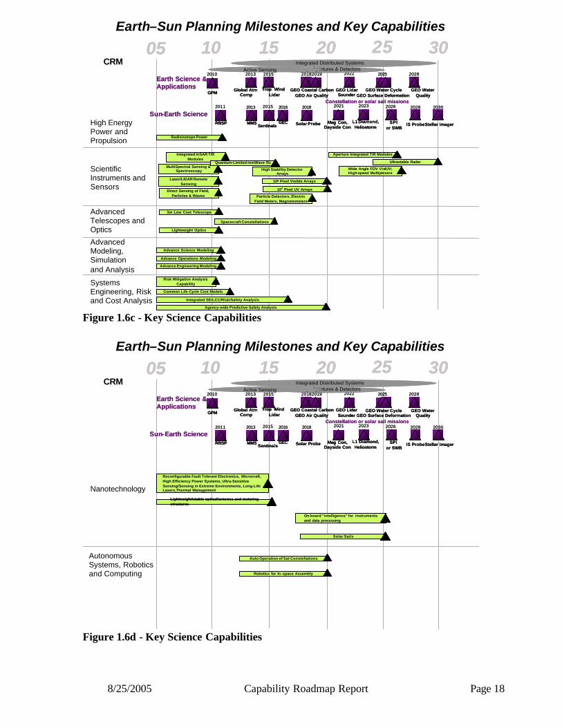
8/25/2005 Capability Roadmap Report Page 18
05 10 15 20 25 3005 10 15 20 25 30Earth–Sun Planning Milestones and Key Capabilities
2015
Trop Wind Lidar
2011
RBSP Solar Probe
2018
2023
Stellar Imager
20302013
MMS SPIor SWB
2026
IS Probe
2028
GEC
2016
L1 Diamond,Heliostorm
Mag Con,Dayside Con
2021Constellation or solar sail missions
Sun-Earth Science
Earth Science & Applications
2010
GPM
2013
Global AtmComp
GEO Coastal CarbonGEO Air Quality
2019 2022
GEO LidarSounder
2025
GEO Water CycleGEO Surface Deformation
GEO Water Quality
2028
2018
Integrated Distributed SystemsLarge Apertures & Detectors
2015
Sentinals
Active Sensing2015
Trop Wind Lidar
2011
RBSP Solar Probe
2018
2023
Stellar Imager
20302013
MMS SPIor SWB
2026
IS Probe
2028
GEC
2016
L1 Diamond,Heliostorm
Mag Con,Dayside Con
2021Constellation or solar sail missions
Sun-Earth Science
Earth Science & Applications
2010
GPM
2013
Global AtmComp
GEO Coastal CarbonGEO Air Quality
2019 2022
GEO LidarSounder
2025
GEO Water CycleGEO Surface Deformation
GEO Water Quality
2028
2018
Integrated Distributed SystemsLarge Apertures & Detectors
2015
Sentinals
Active Sensing
Radioisotope PowerRadioisotope Power
Advanced Modeling, Simulation and Analysis
Advance Science ModelingAdvance Science Modeling
Advance Operations ModelingAdvance Operations Modeling
Advance Engineering ModelingAdvance Engineering Modeling
Common Life Cycle Cost ModelsCommon Life Cycle Cost Models
Risk Mitigation Analysis Capability
Risk Mitigation Analysis Capability
Integrated SE/LCC/Risk/Safety AnalysisIntegrated SE/LCC/Risk/Safety Analysis
Agency-wide Predictive Safety Analysis Agency-wide Predictive Safety Analysis
Systems Engineering, Risk and Cost Analysis
High Energy Power and Propulsion
Scientific Instruments and Sensors
CRM
Advanced Telescopes and Optics
3m Low Cost Telescope3m Low Cost Telescope
Spacecraft ConstellationsSpacecraft Constellations
Lightweight OpticsLightweight Optics
Integrated InSAR T/R Modules
Integrated InSAR T/R Modules
MultiSpectral Sensing & Spectroscopy
MultiSpectral Sensing & Spectroscopy
Laser/LIDAR Remote Sensing
Laser/LIDAR Remote Sensing
Direct Sensing of Field, Particles & Waves
Direct Sensing of Field, Particles & Waves Particle Detectors, Electric
Field Meters, MagnetometersParticle Detectors, Electric
Field Meters, Magnetometers
Quantum-Limited mmWave RxQuantum-Limited mmWave Rx Ultrastable RadarUltrastable Radar
Aperture Integrated T/R ModulesAperture Integrated T/R Modules
High Stability Detector Arrays
High Stability Detector Arrays
108 Pixel Visible Arrays108 Pixel Visible Arrays
Wide Angle FOV Vis/UV; High-speed MultiplexersWide Angle FOV Vis/UV; High-speed Multiplexers
107 Pixel UV Arrays107 Pixel UV Arrays
Figure 1.6c - Key Science Capabilities
05 10 15 20 25 3005 10 15 20 25 30Earth–Sun Planning Milestones and Key Capabilities
2015
Trop Wind Lidar
2011
RBSP Solar Probe
2018
2023
Stellar Imager
20302013
MMS SPIor SWB
2026
IS Probe
2028
GEC
2016
L1 Diamond,Heliostorm
Mag Con,Dayside Con
2021Constellation or solar sail missions
Sun-Earth Science
Earth Science & Applications
2010
GPM
2013
Global AtmComp
GEO Coastal CarbonGEO Air Quality
2019 2022
GEO LidarSounder
2025
GEO Water CycleGEO Surface Deformation
GEO Water Quality
2028
2018
Integrated Distributed SystemsLarge Apertures & Detectors
2015
Sentinals
Active Sensing2015
Trop Wind Lidar
2011
RBSP Solar Probe
2018
2023
Stellar Imager
20302013
MMS SPIor SWB
2026
IS Probe
2028
GEC
2016
L1 Diamond,Heliostorm
Mag Con,Dayside Con
2021Constellation or solar sail missions
Sun-Earth Science
Earth Science & Applications
2010
GPM
2013
Global AtmComp
GEO Coastal CarbonGEO Air Quality
2019 2022
GEO LidarSounder
2025
GEO Water CycleGEO Surface Deformation
GEO Water Quality
2028
2018
Integrated Distributed SystemsLarge Apertures & Detectors
2015
Sentinals
Active SensingCRM
Reconfigurable Fault Tolerant Electronics, Microcraft, High Efficiency Power Systems, Ultra-Sensitive Sensing/Sensing in Extreme Environments, Long-Life Lasers,Thermal Management
Reconfigurable Fault Tolerant Electronics, Microcraft, High Efficiency Power Systems, Ultra-Sensitive Sensing/Sensing in Extreme Environments, Long-Life Lasers,Thermal ManagementNanotechnology
Lightweight/stable optical/antenna and metering structuresLightweight/stable optical/antenna and metering structures
On-board “intelligence” for instruments and data processingOn-board “intelligence” for instruments and data processing
Solar SailsSolar Sails
Auto Operation of Sat ConstellationsAuto Operation of Sat ConstellationsAutonomous Systems, Robotics and Computing Robotics for In -space AssemblyRobotics for In -space Assembly
Figure 1.6d - Key Science Capabilities

8/25/2005 Capability Roadmap Report Page 19
05 10 15 20 25 3005 10 15 20 25 30Universe Planning Milestones and Key Capabilities
JWST
2011
SIM
2012
TPF-C
2016
CON-X
2017
TPF-I
2019 20NN 20NN 20NN 20NN 20NN
LISA
2014
JDEMSequence of large/complex optical systems[SAFIR, Inflation Probe, LUVO, Planet imager, . . .]
JWST
2011
SIM
2012
TPF-C
2016
CON-X
2017
TPF-I
2019 20NN 20NN 20NN 20NN 20NN
LISA
2014
JDEMSequence of large/complex optical systems[SAFIR, Inflation Probe, LUVO, Planet imager, . . .]
3m Low Cost Telescope3m Low Cost Telescope
Gravity Wave DetectionGravity Wave Detection
Formation FlyingFormation Flying
High Contrast ImagingHigh Contrast Imaging
X-ray SpectroscopyX-ray Spectroscopy
Large Baseline OpticsLarge Baseline Optics
Microwave Polarizing OpticMicrowave Polarizing Optic
Cooled TelescopesCooled Telescopes
Observatory ServicingObservatory Servicing
InSpace AssemblyInSpace Assembly
30m Microwave Antenna30m Microwave Antenna
Precision Formation FlyingPrecision Formation Flying
Precise Sensors & ControlPrecise Sensors & Control
20,000m2 Observatory20,000m2 Observatory
High Res X-ray TelescopeHigh Res X-ray Telescope
Advanced Modeling, Simulation and Analysis
Advance Science ModelingAdvance Science Modeling
Advance Operations ModelingAdvance Operations Modeling
Advance Engineering ModelingAdvance Engineering Modeling
Common Life Cycle Cost ModelsCommon Life Cycle Cost Models
Risk Mitigation Analysis Capability
Risk Mitigation Analysis Capability
Integrated SE/LCC/Risk/Safety AnalysisIntegrated SE/LCC/Risk/Safety Analysis
Agency-wide Predictive Safety Analysis Agency-wide Predictive Safety Analysis
Systems Engineering, Risk and Cost Analysis
Scientific Instruments and Sensors
Advanced Telescopes and Optics
CRM
Quantum-Limited GHz RxQuantum-Limited GHz Rx
104 Pixel BLIP Visible Array104 Pixel BLIP Visible Array
High Power, Rapid Sampling Lasers
High Power, Rapid Sampling Lasers
Very Low Mass & Power Direct Sensing of Fields,
Particles & Waves
Very Low Mass & Power Direct Sensing of Fields,
Particles & Waves
High-Efficiency CryocoolerHigh-Efficiency Cryocooler
Quantum-Limited THz RxQuantum-Limited THz Rx
108 Pixel Visible Array108 Pixel Visible Array
104 Pixel BLIP FIR Array104 Pixel BLIP FIR Array
High -Stability, High -Contrast Detector Arrays
High -Stability, High -Contrast Detector Arrays
High Energy Resolution Pixelated XR DetectorsHigh Energy Resolution Pixelated XR Detectors
Large Format UV, XR Detector Arrays
Large Format UV, XR Detector Arrays
High Power, High Stability, Long Lifetime Lasers
High Power, High Stability, Long Lifetime Lasers
Figure 1.6e - Key Science Capabilities
05 10 15 20 25 30Universe Planning Milestones and Key Capabilities
JWST
2011
SIM
2012
TPF-C
2016
CON-X
2017
TPF-I
2019 20NN 20NN 20NN 20NN 20NN
LISA
2014
JDEMSequence of large/complex optical systems[SAFIR, Inflation Probe, LUVO, Planet imager, . . .]
JWST
2011
SIM
2012
TPF-C
2016
CON-X
2017
TPF-I
2019 20NN 20NN 20NN 20NN 20NN
LISA
2014
JDEMSequence of large/complex optical systems[SAFIR, Inflation Probe, LUVO, Planet imager, . . .]
CRM
Very Large Lightweight and stable optical/antenna and metering structuresVery Large Lightweight and stable optical/antenna and metering structures
Nanotechnology
Reconfigurable Fault Tolerant Electronics, Microcraft, High Efficiency Power Systems, Ultra-Sensitive Sensing/Sensing in Extreme Environments,Thermal Management
Reconfigurable Fault Tolerant Electronics, Microcraft, High Efficiency Power Systems, Ultra-Sensitive Sensing/Sensing in Extreme Environments,Thermal Management
Autonomous Control of Formation FlyingAutonomous Control of Formation Flying
Autonomous Systems, Robotics and Computing Robotic In -space AssemblyRobotic In -space Assembly
Robotic In-Space Servicing & MaintenanceRobotic In-Space Servicing & Maintenance
Figure 1.6f - Key Science Capabilities
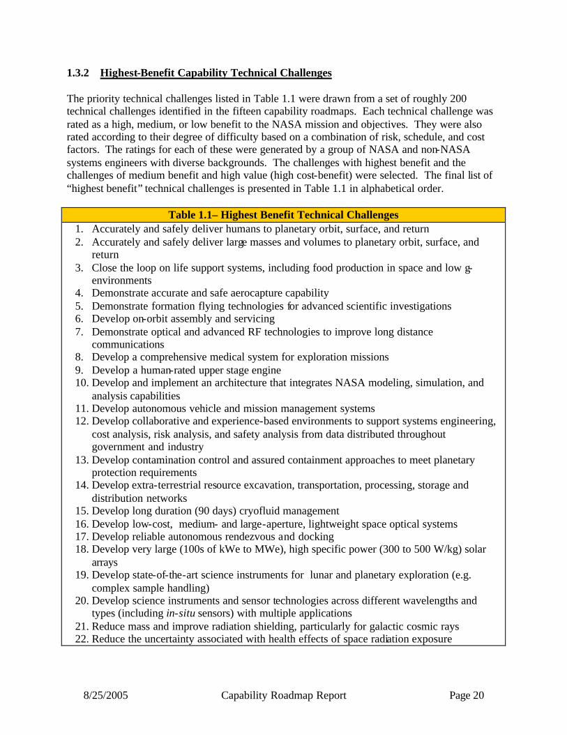
8/25/2005 Capability Roadmap Report Page 20
1.3.2 Highest-Benefit Capability Technical Challenges The priority technical challenges listed in Table 1.1 were drawn from a set of roughly 200 technical challenges identified in the fifteen capability roadmaps. Each technical challenge was rated as a high, medium, or low benefit to the NASA mission and objectives. They were also rated according to their degree of difficulty based on a combination of risk, schedule, and cost factors. The ratings for each of these were generated by a group of NASA and non-NASA systems engineers with diverse backgrounds. The challenges with highest benefit and the challenges of medium benefit and high value (high cost-benefit) were selected. The final list of “highest benefit” technical challenges is presented in Table 1.1 in alphabetical order.
Table 1.1– Highest Benefit Technical Challenges 1. Accurately and safely deliver humans to planetary orbit, surface, and return 2. Accurately and safely deliver large masses and volumes to planetary orbit, surface, and
return 3. Close the loop on life support systems, including food production in space and low g-
environments 4. Demonstrate accurate and safe aerocapture capability 5. Demonstrate formation flying technologies for advanced scientific investigations 6. Develop on-orbit assembly and servicing 7. Demonstrate optical and advanced RF technologies to improve long distance
communications 8. Develop a comprehensive medical system for exploration missions 9. Develop a human-rated upper stage engine 10. Develop and implement an architecture that integrates NASA modeling, simulation, and
analysis capabilities 11. Develop autonomous vehicle and mission management systems 12. Develop collaborative and experience-based environments to support systems engineering,
cost analysis, risk analysis, and safety analysis from data distributed throughout government and industry
13. Develop contamination control and assured containment approaches to meet planetary protection requirements
14. Develop extra-terrestrial resource excavation, transportation, processing, storage and distribution networks
15. Develop long duration (90 days) cryofluid management 16. Develop low-cost, medium- and large-aperture, lightweight space optical systems 17. Develop reliable autonomous rendezvous and docking 18. Develop very large (100s of kWe to MWe), high specific power (300 to 500 W/kg) solar
arrays 19. Develop state-of-the-art science instruments for lunar and planetary exploration (e.g.
complex sample handling) 20. Develop science instruments and sensor technologies across different wavelengths and
types (including in-situ sensors) with multiple applications 21. Reduce mass and improve radiation shielding, particularly for galactic cosmic rays 22. Reduce the uncertainty associated with health effects of space radiation exposure

8/25/2005 Capability Roadmap Report Page 21
Table 1.1– Highest Benefit Technical Challenges 23. Reestablish nuclear fission infrastructure for power and propulsion needs 24. Research nanostructure materials, such as nanotube-based fibers and ultra- lightweight
durable insulation 1.3.3 The Capability Roadmap Development Process The underlying philosophy for the roadmap development was to include participants from across the nation. The roadmap teams were comprised of technical experts from academia, industry, NASA, and other Government Agencies. Each team was co-chaired by a NASA and non-NASA subject matter expert. The membership was comprised approximately of 2/3 non-NASA technical experts and 1/3 NASA technical experts. This structure was meant to ensure a national perspective and mitigate institutional biases. In November 2004, the general public was invited to participate in a Request for Information (RFI) followed by a workshop where the authors of the RFI responses could brief their perspective ideas on capabilities to the roadmap chairs. Over 500 white papers were submitted and presented at the workshop. Thorough discussions were held regarding the scope and content of each roadmap area. A group of NASA coordinators were asked to identify interfaces and dependencies between the fifteen roadmaps and eliminate duplication or overlap of scope between roadmaps. A crosswalk tool (see figure 1.7) was developed to track dependencies between roadmaps. Coordinators from NASA HQ Mission Directorates ensured that resources were available to the teams and provided management direction and oversight. The capability roadmap teams were chartered to provide the technical knowledge and expertise required to develop the roadmaps and identify the capabilities needed to meet the Vision. The capability roadmap teams identified and analyzed technologies and technical challenges, assessed the current state of the art, estimated the development time to achieve the capabilities, and identified key architectural and strategic decisions that would affect the direction of the roadmaps. As the roadmap efforts progressed, several capability roadmap teams coordinated information with relevant strategic roadmap teams in order to aid the development of implementable strategies. To guide and independently assess the roadmap activity, NASA requested that the Aeronautics and Space Engineering Studies Board of the National Academy of Sciences (NAS) to provide a two-step evaluation of the capability roadmaps. The first step was to have fifteen individual NAS expert panels assess the capability roadmaps at an interim state and provide verbal feedback on their progress. As the strategic roadmaps were being developed in parallel with the capability roadmaps, the capability roadmap teams made assumptions about certain aspects of a strategic architecture on which to base their capability development. This was done with the intention of updating the roadmaps later to reflect the output of the strategic roadmaps.
8/25/2005 Capability Roadmap Report Page 22
Thirteen of the fifteen roadmap reviews took place during the month of March 2005, and the NAS provided excellent feedback. The two remaining roadmaps completed their materials. However, acceleration of the roadmapping schedule did not allow for a NAS review. The second step was to have one NAS panel comprised of a subset of members from the original fifteen panels review the completed capability roadmaps, now fully integrated with strategic roadmaps, and provide NASA with a letter report. The goal was to provide credibility and crosscheck to the roadmapping activity by including expert analysis and commentary from the NAS. This phase was not completed, as the roadmaps needed to be made available to the architecture teams by May 22, 2005. In April 2005, the strategic roadmaps provided interim reports that included key strategies. A snapshot of the missions and milestones identified in the strategic roadmap activities is shown in Figures 1a and 1b. These were used in this final report for planning purposes to ensure that all fifteen capability roadmap teams were using the same dates and mission assumptions. The final integration of the strategic and capability roadmaps was scheduled to occur with the roadmap integration team and architecture synthesis process. Several elements of the capability roadmap products were not completed due to the acceleration of the schedule. These include:
• Identification and assessment of capability gaps that were not included in the original scope of the fifteen roadmaps
• Integration with the strategic roadmaps • Cost and risk estimates • Identification of breakthrough technology investment areas • Infrastructure assessments (i.e. skills, competencies, workforce, and facilities) • Cross-trades among capabilities

8/25/2005 Capability Roadmap Report Page 23
Figure 1.7 – Dependency Crosswalk Tool
2. H
igh-
ener
gy p
ower
an
d pr
opul
sion
3. I
n-sp
ace
tran
spor
tati
on
4. A
dvan
ced
tele
scop
es
and
obse
rvat
orie
s
5.C
omm
unic
atio
n &
N
avig
atio
n
6. R
obot
ic a
cces
s to
pl
anet
ary
surf
aces
7. H
uman
pla
neta
ry
land
ing
syst
ems
8. H
uman
hea
lth
and
supp
ort
syst
ems
9. H
uman
exp
lora
tion
sy
stem
s an
d m
obili
ty
10. A
uton
omou
s sy
stem
s an
d ro
boti
cs
11. T
rans
form
atio
nal
spac
epor
t/ra
nge
tech
nolo
gies
12.
Sci
enti
fic
inst
rum
ents
and
sen
sors
13. I
n si
ture
sour
ce
utili
zati
on
14. A
dvan
ced
mod
elin
g,
sim
ulat
ion,
ana
lysi
s
15. S
yste
ms
engi
neer
ing
cost
/ris
k an
alys
is
16. N
anot
echn
olog
y
2. High-energy power and propulsion3. In-space transportation
4. Advanced telescopes and observatories5. Communication & Navigation
6. Robotic access to planetary surfaces
7. Human planetary landing systems
8. Human health and support systems
9. Human exploration systems and mobility
10. Autonomous systems and robotics
15. Systems engineering cost/risk analysis
16. Nanotechnology
11. Transformational spaceport/range technologies
12. Scientific instruments and sensors
13. In situ resource utilization
14. Advanced modeling, simulation, analysis
Same element
Critical Relationship (dependent, enabling)
Moderate Relationship (enhancing, synergistic)
No Relationship
Needs negotiation/difference of opinion
1.3.4 Additional Sources of Information This document is supported by more in-depth analysis and information, which is available on CD or via hard copy. Over 500 white papers that were submitted by the public via the RFI are also available. Contact information for the key technical experts responsible for each roadmap is shown in Table 1.2.

8/25/2005 Capability Roadmap Report Page 24
Table 1.2: Contact Information for Roadmap Chairs Roadmap Expert Phone Email High Energy Power and Propulsion Joe Nainiger 216-977-7103 [email protected]
In-Space Transportation Paul McConnaughey 256-544-1599 [email protected] Advanced Telescopes and Observatories Lee Feinberg 301-286-5923 [email protected]
Communication and Navigation Bob Spearing 202-358-4780 [email protected]
Robotic Access to Planetary Surface Mark Adler 818-354-6277 [email protected]
Human Planetary Landing Systems Rob Manning 818-393-7815 [email protected]
Human Health & Support Systems Dennis Grounds 281-483-6338 [email protected]
Human Exploration Systems and Mobility Christopher Culbert 281-483-8080 [email protected]
Autonomous Systems Robotics and Computing James Crawford 650-604-1139 [email protected]
Transformational Spaceport and Range Karen Poniatowski 202-358-2469 [email protected]
Scientific Instruments and Sensors Richard Barney 301-286-9588 [email protected]
In-situ Resource Utilization Gerry Sanders 281-483-9066 [email protected] Advanced Modeling and Simulation Erik Antonsson 818-393-7600 [email protected]
Systems Engineering Cost Risk analysis Steve Cavanaugh 757-864-7019 [email protected]
Nanotechnology Murray Hirschbein Minoo Dastoor
202-358-4662 202-358-4518
[email protected] [email protected]
1.3.5 Individual Capability Roadmap Summaries The following sections (2 through 16) of this report include, at an executive level, the fifteen individual capability roadmaps. More detailed roadmaps are also available on CD. In these summaries, the Roadmap teams have included the following information:
• Capability description • Benefits of the capability • Key Architecture / Strategic decisions that affect the direction of the capability
development • Major technical challenges • Key capabilities • Capability assessment (capabilities on the roadmap) • Capability scope (Capability Breakdown Structure) • Capability roadmap • Relationships to other roadmaps • Infrastructure assessment
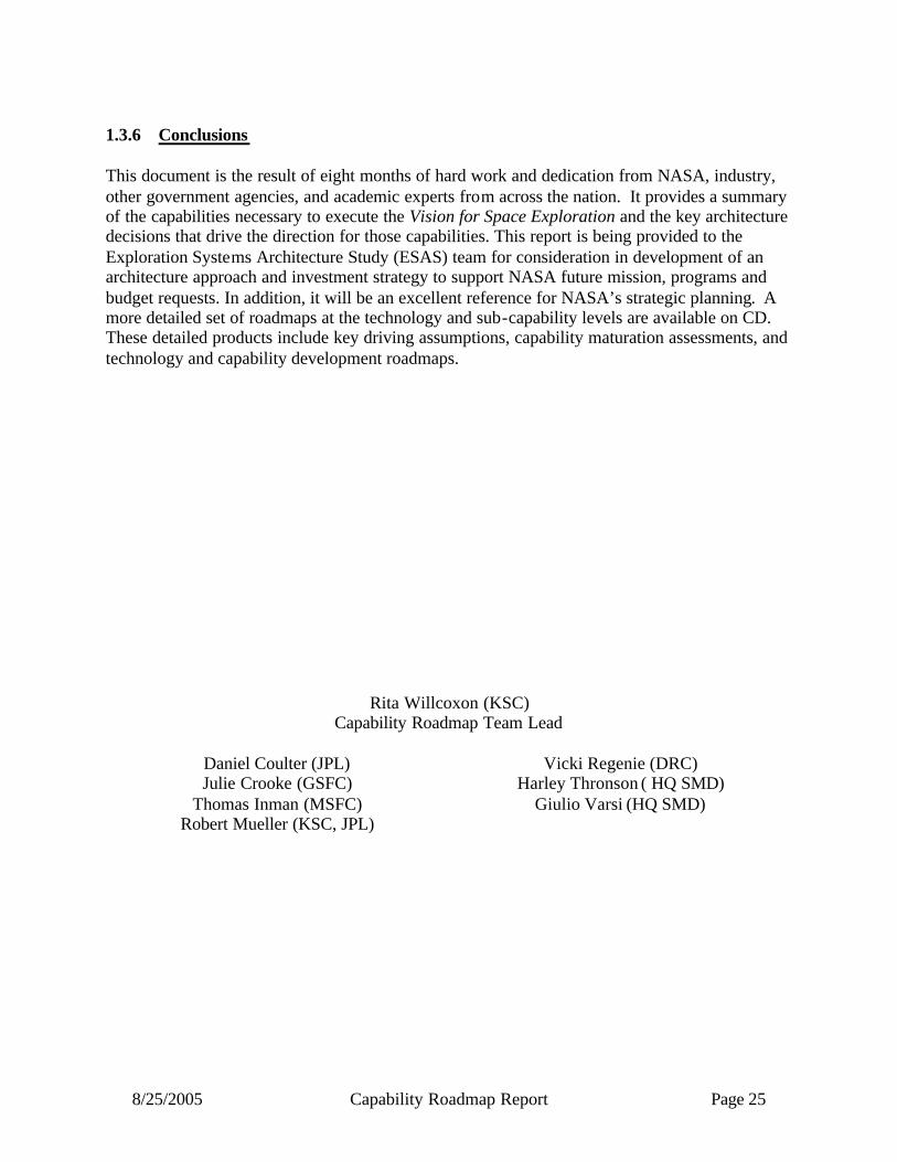
8/25/2005 Capability Roadmap Report Page 25
1.3.6 Conclusions This document is the result of eight months of hard work and dedication from NASA, industry, other government agencies, and academic experts from across the nation. It provides a summary of the capabilities necessary to execute the Vision for Space Exploration and the key architecture decisions that drive the direction for those capabilities. This report is being provided to the Exploration Systems Architecture Study (ESAS) team for consideration in development of an architecture approach and investment strategy to support NASA future mission, programs and budget requests. In addition, it will be an excellent reference for NASA’s strategic planning. A more detailed set of roadmaps at the technology and sub-capability levels are available on CD. These detailed products include key driving assumptions, capability maturation assessments, and technology and capability development roadmaps.
Rita Willcoxon (KSC) Capability Roadmap Team Lead
Daniel Coulter (JPL) Julie Crooke (GSFC)
Thomas Inman (MSFC) Robert Mueller (KSC, JPL)
Vicki Regenie (DRC) Harley Thronson ( HQ SMD)
Giulio Varsi (HQ SMD)
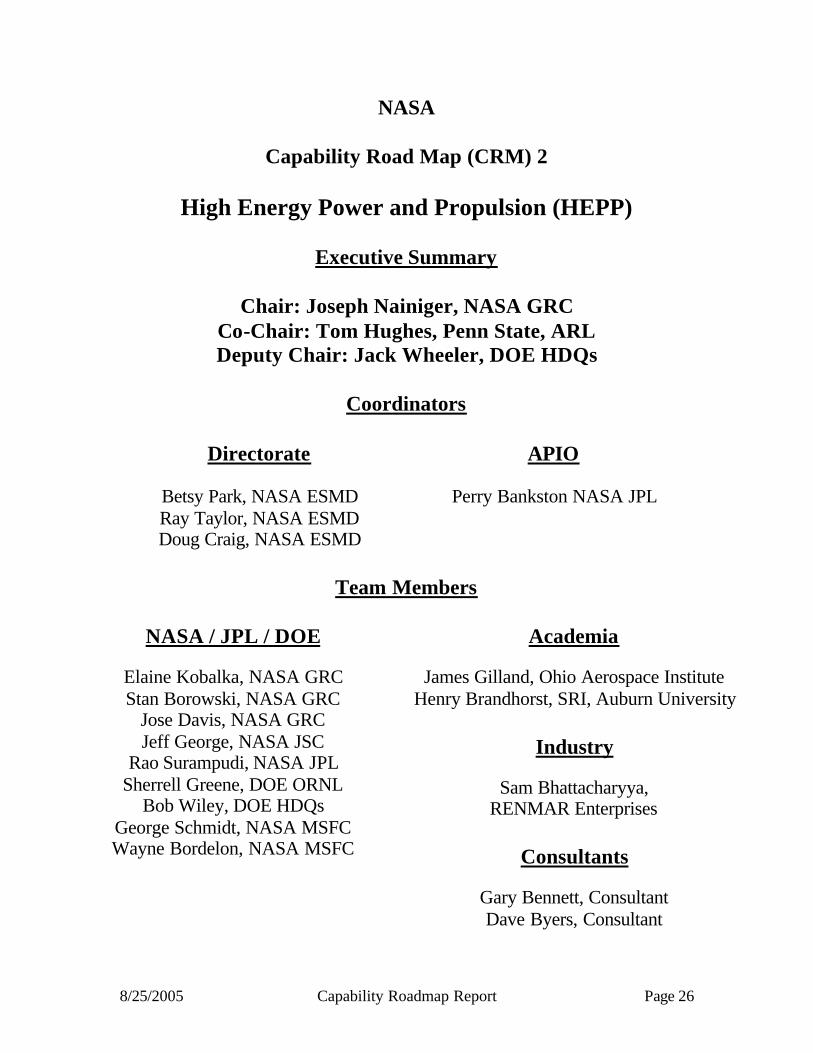
8/25/2005 Capability Roadmap Report Page 26
NASA
Capability Road Map (CRM) 2
High Energy Power and Propulsion (HEPP)
Executive Summary
Chair: Joseph Nainiger, NASA GRC Co-Chair: Tom Hughes, Penn State, ARL Deputy Chair: Jack Wheeler, DOE HDQs
Coordinators
Directorate
Betsy Park, NASA ESMD Ray Taylor, NASA ESMD Doug Craig, NASA ESMD
APIO
Perry Bankston NASA JPL
Team Members
NASA / JPL / DOE
Elaine Kobalka, NASA GRC Stan Borowski, NASA GRC
Jose Davis, NASA GRC Jeff George, NASA JSC
Rao Surampudi, NASA JPL Sherrell Greene, DOE ORNL
Bob Wiley, DOE HDQs George Schmidt, NASA MSFC Wayne Bordelon, NASA MSFC
Academia
James Gilland, Ohio Aerospace Institute Henry Brandhorst, SRI, Auburn University
Industry
Sam Bhattacharyya,
RENMAR Enterprises
Consultants
Gary Bennett, Consultant Dave Byers, Consultant
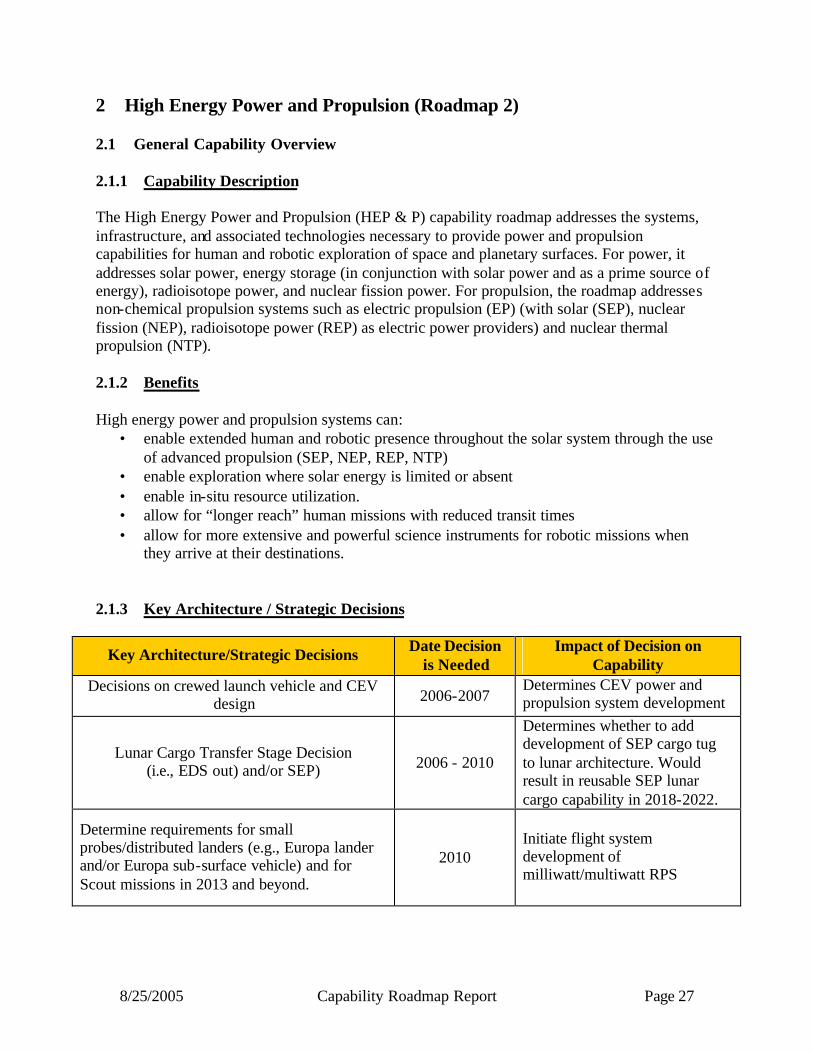
8/25/2005 Capability Roadmap Report Page 27
2 High Energy Power and Propulsion (Roadmap 2) 2.1 General Capability Overview 2.1.1 Capability Description The High Energy Power and Propulsion (HEP & P) capability roadmap addresses the systems, infrastructure, and associated technologies necessary to provide power and propulsion capabilities for human and robotic exploration of space and planetary surfaces. For power, it addresses solar power, energy storage (in conjunction with solar power and as a prime source of energy), radioisotope power, and nuclear fission power. For propulsion, the roadmap addresses non-chemical propulsion systems such as electric propulsion (EP) (with solar (SEP), nuclear fission (NEP), radioisotope power (REP) as electric power providers) and nuclear thermal propulsion (NTP). 2.1.2 Benefits High energy power and propulsion systems can:
• enable extended human and robotic presence throughout the solar system through the use of advanced propulsion (SEP, NEP, REP, NTP)
• enable exploration where solar energy is limited or absent • enable in-situ resource utilization. • allow for “longer reach” human missions with reduced transit times • allow for more extensive and powerful science instruments for robotic missions when
they arrive at their destinations. 2.1.3 Key Architecture / Strategic Decisions
Key Architecture/Strategic Decisions Date Decision is Needed
Impact of Decision on Capability
Decisions on crewed launch vehicle and CEV design 2006-2007
Determines CEV power and propulsion system development
Lunar Cargo Transfer Stage Decision (i.e., EDS out) and/or SEP) 2006 - 2010
Determines whether to add development of SEP cargo tug to lunar architecture. Would result in reusable SEP lunar cargo capability in 2018-2022.
Determine requirements for small probes/distributed landers (e.g., Europa lander and/or Europa sub-surface vehicle) and for Scout missions in 2013 and beyond.
2010 Initiate flight system development of milliwatt/multiwatt RPS

8/25/2005 Capability Roadmap Report Page 28
Key Architecture/Strategic Decisions Date Decision
is Needed Impact of Decision on
Capability
Decision on lunar cargo launch vehicle. 2010
Will determine masses, volumes, and performance capabilities for power systems and propulsion stages.
Determine power and mass requirements for Europa and Titan missions, New Frontiers 4, 5, 6, Neptune Orbiter and Europa Lander or Advanced Titan Missions.
2012
Initiate flight system hardware development of Advanced 100 We class RPS and sub-kilowatt EP for REP.
Determine NASA requirements for lunar human habitat power and Mars precursor missions (Mars Scaled Human Precursor and Mars Dynamic Mission.)
2013 Initiate multi-kilowatt RPS flight hardware development.
Decision on in-space transfer stages for human Mars missions (cargo and piloted). Initiate nuclear propulsion flight development program.
2015 Long- lead time development for Nuclear Propulsion Systems and/or MWe SEP systems .
Determine Mars surface activities for human exploration (i.e., number of crew, habitats, ISRU, etc.) Decide on and initiate flight hardware development programs.
2020
Determines Mars surface power system development, including long- lead time development for nuclear fission power.
2.1.4 Major Technical Challenges 2006-2010
• Nuclear fission infrastructure reestablishment (nuclear fuels, power subsys tem and system ground test facilities.)
• Work in space nuclear fission power/propulsion has been dormant for many years. Need to recapture nuclear fission technology from past programs (i.e., Rover, Nerva, SP-100…) and start new developments immediately.
• Human-rated nuclear reactor shielding.
• Space Qualified Dynamic power conversion (Brayton, Stirling, or Rankine) needed for high power nuclear fission power systems. Need to develop robust, reliable dynamic power conversion.
• Heat rejection radiators for nuclear fission power systems are inherently large and current state-of-practice are massive. Need to develop lightweight, autonomously deployable heat rejection radiators.
• Development of large, long- lived electric propulsion thruster technology for nuclear and solar electric propulsion.
• Development of very large (100s of kWe to MWe), high specific power (300 to 500 W/kg) solar arrays.
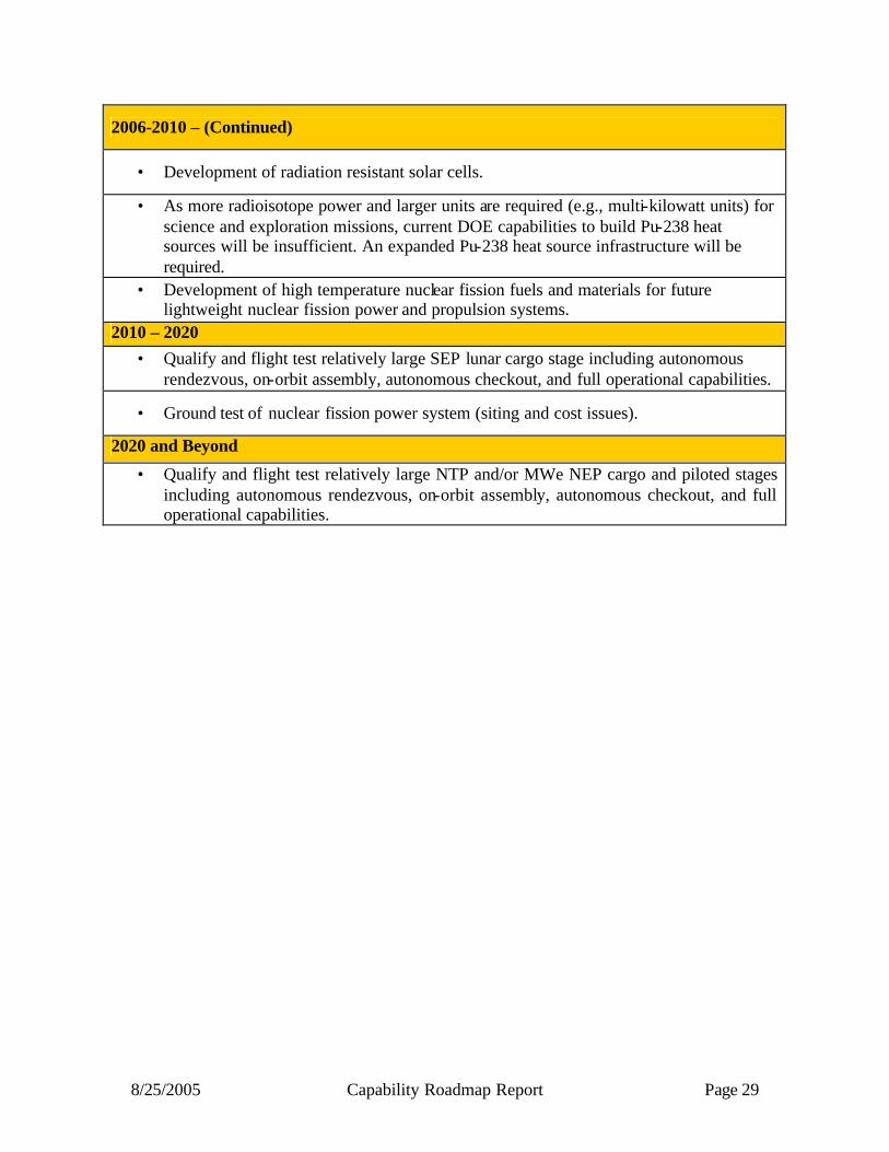
8/25/2005 Capability Roadmap Report Page 29
2006-2010 – (Continued)
• Development of radiation resistant solar cells.
• As more radioisotope power and larger units are required (e.g., multi-kilowatt units) for science and exploration missions, current DOE capabilities to build Pu-238 heat sources will be insufficient. An expanded Pu-238 heat source infrastructure will be required.
• Development of high temperature nuclear fission fuels and materials for future lightweight nuclear fission power and propulsion systems.
2010 – 2020 • Qualify and flight test relatively large SEP lunar cargo stage including autonomous
rendezvous, on-orbit assembly, autonomous checkout, and full operational capabilities.
• Ground test of nuclear fission power system (siting and cost issues).
2020 and Beyond
• Qualify and flight test relatively large NTP and/or MWe NEP cargo and piloted stages including autonomous rendezvous, on-orbit assembly, autonomous checkout, and full operational capabilities.

8/25/2005 Capability Roadmap Report Page 30
2.1.5 Key Capabilities and Status The Vision will require extraordinary advances in power and propulsion capabilities compared to current state-of-the-practice systems. Chief among those capabilities is the development of nuclear fission power and propulsion systems and vehicles. Nuclear power and propulsion is enabling for long-term human lunar base occupancy, the use of large scale in-situ resource utilization on the lunar and Mars surfaces, and fo r the transport of humans and cargo to Mars. Although nuclear power and propulsion offer the promise of enabling capability, the long- lead times to develop these systems and the accompanying investment in the required reestablishment of infrastructure will provide technology and development challenges. Likewise, the development of radioisotope power systems is key to future robotic deep space probes, large robotic Mars landers and rovers, and demanding robotic missions to the surfaces of Venus, Europa, and Titan. Advances in solar power systems and capabilities will provide lighter weight and greater science capability for inner solar system robotic missions. Likewise, key developments in electric propulsion (higher performance and thruster power, and longer lived components) will enable a range of greater science capability using either solar,nuclear, or radioisotope power sources. Radioisotope electric propulsion offers significant benefits for robotic science probes to destinations having small gravity wells (i.e., Trojan asteroids).The use of reusable solar electric propulsion tugs to ferry cargo to moon and/or Mars offers a potentially cost effective means of cargo transfer. Table 2.1 - Key Capabilities
Capability/Sub-Capability
Mission or Roadmap Enabled
Current State of Practice
Minimum Estimated Development Time
(years)
Spacecraft Nuclear fission power
Robotic & human
missions to Mars & beyond
Prometheus I under development
~ 10 years
Nuclear fission power for planetary surfaces
Lunar and Mars
Human Missions
Not under development ~ 13 years
Radioisotope power
Robotic & human
missions of all types
Multi Mission Radioisotope Thermoelectric Generator (MMRTG) and Stirling
Radioisotope Generator (SRG) under development with
General Purpose Heat Source. (GPHS)
4--8 years
Solar power for spacecraft and
planetary surfaces
Robotic & human
missions of all types
Used on > 99% of missions to date, including spacecraft,
surface and SEP. 5-8 years
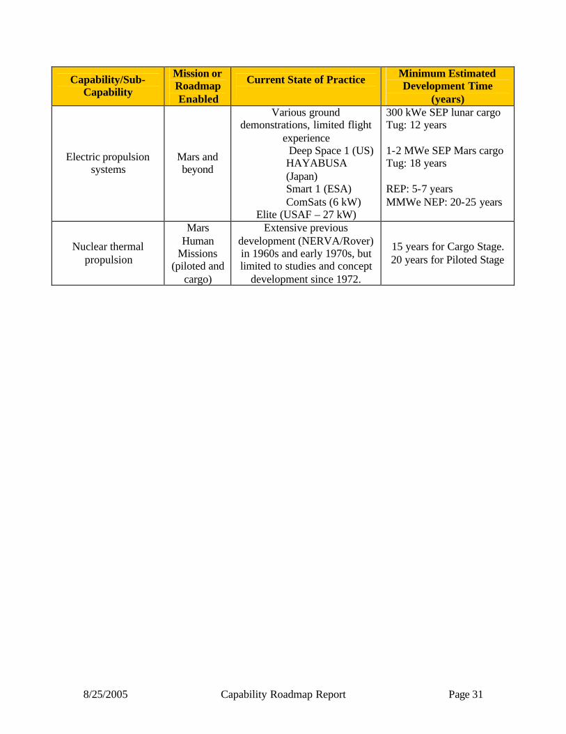
8/25/2005 Capability Roadmap Report Page 31
Capability/Sub-Capability
Mission or Roadmap Enabled
Current State of Practice
Minimum Estimated Development Time
(years)
Electric propulsion systems
Mars and beyond
Various ground demonstrations, limited flight
experience Deep Space 1 (US) HAYABUSA (Japan) Smart 1 (ESA) ComSats (6 kW)
Elite (USAF – 27 kW)
300 kWe SEP lunar cargo Tug: 12 years 1-2 MWe SEP Mars cargo Tug: 18 years REP: 5-7 years MMWe NEP: 20-25 years
Nuclear thermal propulsion
Mars Human
Missions (piloted and
cargo)
Extensive previous development (NERVA/Rover) in 1960s and early 1970s, but limited to studies and concept
development since 1972.
15 years for Cargo Stage. 20 years for Piloted Stage
8/25/2005 Capability Roadmap Report Page 32
2.2 Roadmap Development 2.2.1 Legacy Activities and Roadmap Assumptions Based on emerging strategies, the team assumed that nuclear power and advanced propulsion systems would be required to fulfill the Vision for Space Exploration. It was also recognized that solar power and propulsion systems (especially solar electric propulsion) would be effective in many human exploration and future science applications. Sub-capabilities such as power management and distribution, power conversion, heat rejection, and materials technology were recognized as being “cross-cutting” and apply to all of the roadmap capabilities. A key assumption was each individual roadmap was intended to be technically achievable in a focused effort. No assumptions were made as to budget priorities or preferences. It was assumed that a “reasonable” program of technology development and advanced development could lead to the capabilities resulting in the roadmaps at the end of this report within the time-frame shown. For human exploration, these included the crew exploration vehicle, lunar and Mars surface power applications, and especially piloted and cargo propulsion systems for Mars and beyond. For science missions, driving missions included lunar and Mars orbiters, planetary landers, outer planetary probes, and other demanding outer planetary missions requiring high power and/or a high degree of maneuverability and/or multiple destinations (such as the Jupiter Icy Moons Orbiter mission 2.2.2 Capability Breakdown Structure Figure 2.1 shows the Capability Breakdown Structure (CBS) for the High Energy Power & Propulsion (HEP & P) Roadmap activity. Each of the major items identified across the top represent a major power or propulsion human exploration or science capability to be satisfied. Those items are Robotic Surface Power (2.1), Human Exploration Surface Power (2.2), Science & Robotic Spacecraft Power (2.3), CEV Power (2.4), Robotic Planetary Propulsion (2.5), and Human Exploration Propulsion (2.6). The sub-capabilities below these major capabilities represent potential system capabilities that could satisfy the major capabilities. As described earlier, the HEP & P sub-teams were organized to represent the sub-capabilities to meet the major capabilities. Converters, power management and distribution, heat rejection, and materials were shown to support all capabilities.
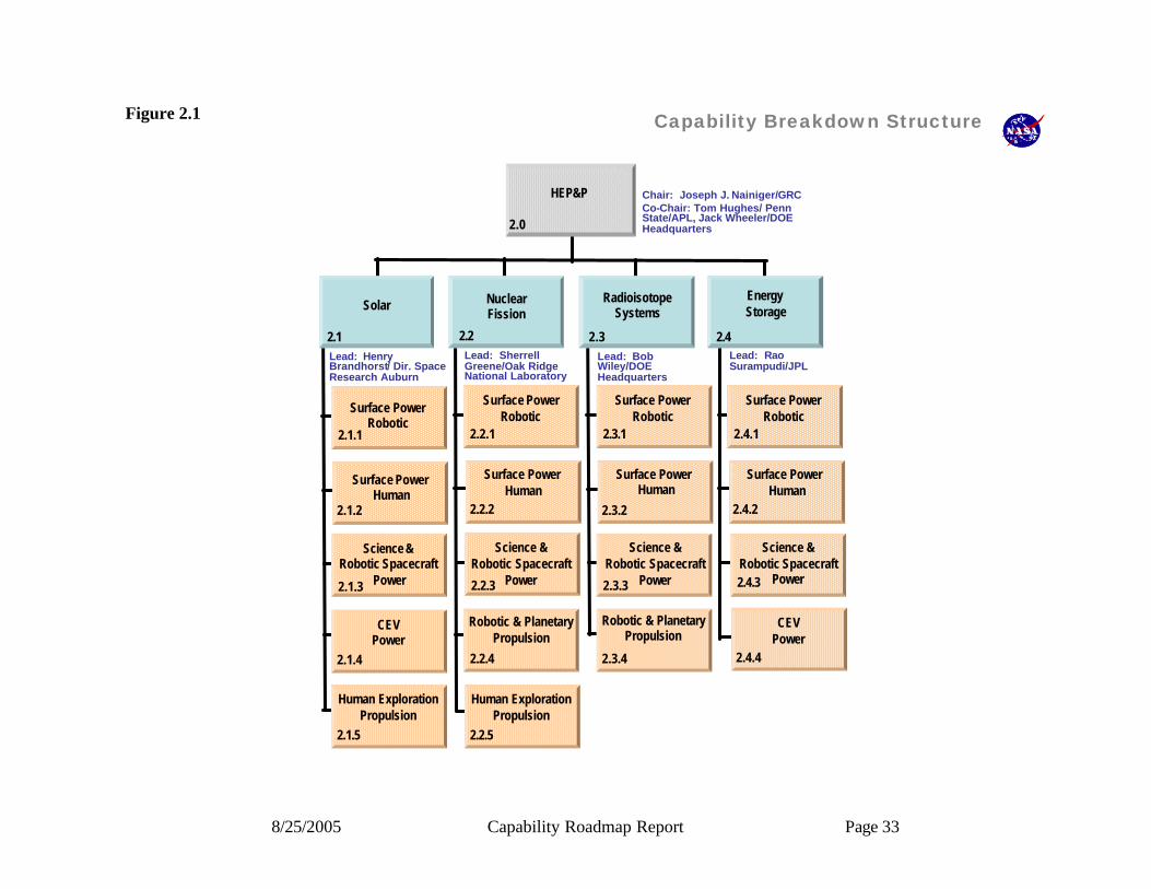
8/25/2005 Capability Roadmap Report Page 33
Figure 2.1 Capability Breakdown Structure
2.1Lead: Henry Brandhorst/ Dir. Space Research Auburn
Solar
2.1.1
2.1.2
2.1.3
2.1.4
Lead: SherrellGreene/Oak Ridge National Laboratory
2.2.1
2.2.2
2.2.3
Lead: Bob Wiley/DOE Headquarters
2.3.1
2.3.2
2.3.3
2.3.4
Lead: RaoSurampudi/JPL
2.4.1
2.4.2
2.4.3
2.4.4
2.2 2.3 2.4
HEP&P Chair: Joseph J. Nainiger/GRCCo-Chair: Tom Hughes/ Penn State/APL, Jack Wheeler/DOE Headquarters2.0
2.2.4
EnergyStorage
Nuclear Fission
RadioisotopeSystems
Surface PowerRobotic
Surface PowerHuman
Science &Robotic Spacecraft
Power
CEVPower
2.1.5
Human Exploration Propulsion
Surface PowerRobotic
Surface PowerHuman
Science &Robotic Spacecraft
Power
Robotic & PlanetaryPropulsion
2.2.5
Human Exploration Propulsion
Surface PowerRobotic
Surface PowerHuman
Science &Robotic Spacecraft
Power
Robotic & PlanetaryPropulsion
Surface PowerRobotic
Surface PowerHuman
Science &Robotic Spacecraft
Power
CEVPower

8/25/2005 Capability Roadmap Report Page 34
2.2.3 Roadmap Logic The capability roadmap in this report is a summary level roadmap. This summary level roadmap includes only a roll up of the key sub-capabilities milestone readiness to support a particular mission requirement. Detailed sub-capability and technology roadmaps showing the technology progression and sub-capability development were presented to the NAS and are available in the document sharing system. In the top blue banner of the roadmap, there are those key missions that are pertinent to the roadmap among those derived from the April 15, 2005 interim document delivered by the strategic roadmaps and displayed in the CRM Planning Milestones Chart. The green banner below represents a summary rollup of key capabilities from each of the various capability breakdown structure elements. The peach colored swim-lanes represent the individual top level capability breakdown structure element and the sub-capabilities within this roadmap. The triangles represent the date that the capability is ready to support a given mission, and the diamonds represent decision points. Because of the large number of technologies that can be selected to produce a specific power system, and since the optimum combination of these technologies is highly dependant on the power system operating requirements, the roadmaps presented show broad system types without showing the subsystem selection process leading to the roadmapped system. Typical performance metrics are included on the system where existing data, ongoing programs or in depth study allows. The continual evolution of all the supporting technologies gives these metrics a limited life in many cases and the possibility of an unexpected, and profound, breakthrough is possible; particularly in the case of less well developed technologies. Therefore, the presented roadmaps offer a reasoned picture of how the various technologies appear to support the various missions, some of which are loosely defined themselves today. The consequence of these circumstances is that the roadmaps provide a point of departure for making coarse discriminations between alternative approaches. More detailed comparisons will be required to differentiate between the more promising approaches as mission requirements become more specific. The CRM-2 team has produced both Exploration and Science roadmaps to further simplify the presentation of the extensive alternatives previously mentioned. This approach also lends itself well to the somewhat unique and different character of power systems optimized for these two classes of systems.

8/25/2005 Capability Roadmap Report Page 35
2.1 Surface Power Robotic
2.3 Science & Robotic Spacecraft Power
2.5 Robotic Planetary Propulsion
2005 2010 20202015
MMRTG
SRG
Milliwatt / multi-watt RPS
MMRTG
SRG
Milliwatt / multi-watt RPS
100-200kWe NEP class(Prometheus-1)
200 W/kg PV array
300 W/kg array
MSL 1 MarsSample
return
SolarProbeNew Frontier 2
Small probes, distributed , landers,outer planet probes
(Europa, Titan, Neptune etc.)RoboticScience TBD
Milliwatt / multi-watt class RPSSOP 100 We
class RPS
Robotic Science NEP Vehicle
MarsScout
VISE
SAFIR
SIM
Advanced S/C PV array
Low temp batt -40 C
Low tempbatt -60 C
Flywheels 100 Wh/kg
Long life batt 100 Wh/kgPrim batt 400 W/kg
Long life batt 160 W/kg
Flywheels 200 Wh/kg
Orbiter Power
LRO
Mars Orbiters/Rovers
Rover Power
Rover Power
Outer planetS/C power
Mars Orbiter
Advanced RPS
Sub-kilowatt EP
Advanced RPS
REP
Kilowatt – class RPS
Prim batt 600 W/kg
Advanced 100 Weclass RPS
OrbiterPower
K We class RPS
Mars AFLPrecursor Mission
Phoenix
2.0 High EnergyPower and Propulsion Capability Road Map(Key Events/Milestones)
Key Assumptions Robotic Science Missions
MarsScout
MHP 1
Capability Roadmaps: High Energy Power & Propulsion (HEPP)(Science)
Capability/Sub-Capability/Major Accomplishment
Capability/Sub-Capability/Demonstrated or Established
CRM Milestone/Mission
Major Decision
Range of Dates
Development Timelines
Legend
Capability/Sub-Capability/Major Accomplishment
Capability/Sub-Capability/Demonstrated or Established
CRM Milestone/Mission
Major Decision
Range of Dates
Development Timelines
Legend
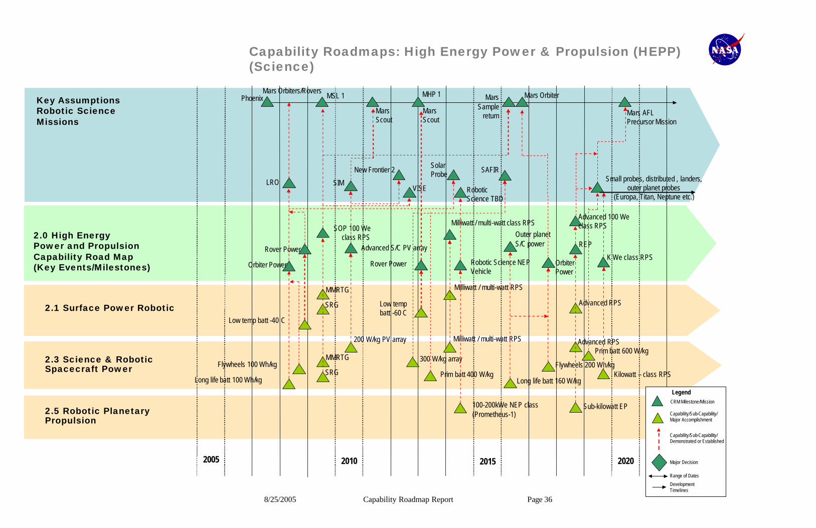
8/25/2005 Capability Roadmap Report Page 36
2.1 Surface Power Robotic
2.3 Science & Robotic Spacecraft Power
2.5 Robotic Planetary Propulsion
2005 2010 20202015
MMRTG
SRG
Milliwatt / multi-watt RPS
MMRTG
SRG
Milliwatt / multi-watt RPS
100-200kWe NEP class(Prometheus-1)
200 W/kg PV array
300 W/kg array
MSL 1 MarsSample
return
SolarProbeNew Frontier 2
Small probes, distributed , landers,outer planet probes
(Europa, Titan, Neptune etc.)RoboticScience TBD
Milliwatt / multi-watt class RPSSOP 100 We
class RPS
Robotic Science NEP Vehicle
MarsScout
VISE
SAFIR
SIM
Advanced S/C PV array
Low temp batt -40 C
Low tempbatt -60 C
Flywheels 100 Wh/kg
Long life batt 100 Wh/kgPrim batt 400 W/kg
Long life batt 160 W/kg
Flywheels 200 Wh/kg
Orbiter Power
LRO
Mars Orbiters/Rovers
Rover Power
Rover Power
Outer planetS/C power
Mars Orbiter
Advanced RPS
Sub-kilowatt EP
Advanced RPS
REP
Kilowatt – class RPS
Prim batt 600 W/kg
Advanced 100 Weclass RPS
OrbiterPower
K We class RPS
Mars AFLPrecursor Mission
Phoenix
2.0 High EnergyPower and Propulsion Capability Road Map(Key Events/Milestones)
Key Assumptions Robotic Science Missions
MarsScout
MHP 1
Capability Roadmaps: High Energy Power & Propulsion (HEPP)(Science)
Capability/Sub-Capability/Major Accomplishment
Capability/Sub-Capability/Demonstrated or Established
CRM Milestone/Mission
Major Decision
Range of Dates
Development Timelines
Legend
Capability/Sub-Capability/Major Accomplishment
Capability/Sub-Capability/Demonstrated or Established
CRM Milestone/Mission
Major Decision
Range of Dates
Development Timelines
Legend

8/25/2005 Capability Roadmap Report Page 37
2.2 Surface Power Human
2.6 Human Exploration Propulsion
2.0 High EnergyPower and Propulsion Capability Road Map(Key Events/Milestones)
2005 2010 20202015
CEV 2008 Demo
First Crewed CEV Flight2014
Earliest First Human Lunar Mission
2017
CEV Power SystemScience package& rover power
Power for humanlunar expeditions Lunar Cargo Propulsion
>150 W/kg Lunar Array
200-500 kWe SEP Cargo Vehicle
Astronaut suit power
Long life batt 160 Wh/kg
Prim batt 400 W/kg
Fuel cells 400 W/kg
Regen fuel cells 400 Wh/kg Advanced 100 Weclass RPS
Capability Roadmaps: High Energy Power & Propulsion (HEPP)(Exploration)
Key Assumptions Exploration Missions
Lunar Mission
Capability/Sub-Capability/Major Accomplishment
Capability/Sub-Capability/Demonstrated or Established
CRM Milestone/Mission
Major Decision
Range of Dates
Development Timelines
Legend
Capability/Sub-Capability/Major Accomplishment
Capability/Sub-Capability/Demonstrated or Established
CRM Milestone/Mission
Major Decision
Range of Dates
Development Timelines
Legend
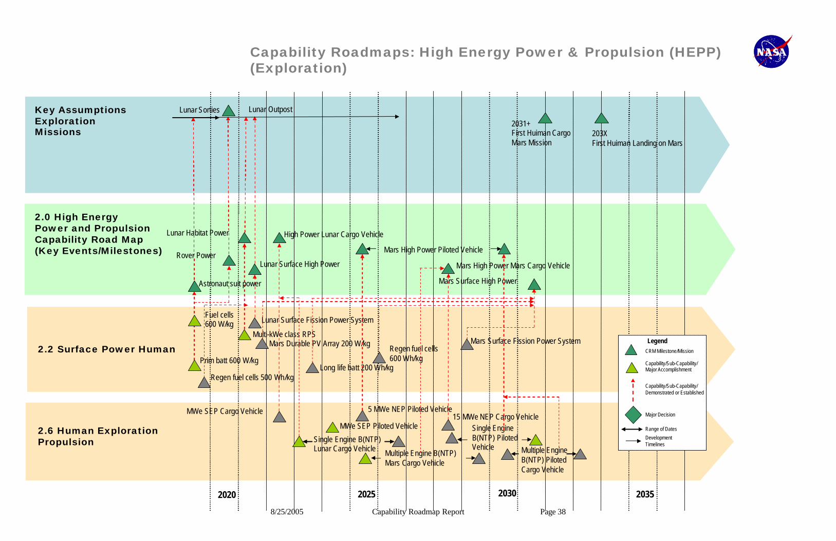
8/25/2005 Capability Roadmap Report Page 38
2020 2025 20352030
2.2 Surface Power Human
2.6 Human Exploration Propulsion
High Power Lunar Cargo VehicleLunar Habitat Power
Mars High Power Piloted Vehicle
Mars High Power Mars Cargo VehicleLunar Surface High Power
Mars Surface High Power
Lunar Surface Fission Power System
Multi-kWe class RPSMars Surface Fission Power System
MWe SEP Cargo Vehicle
MWe SEP Piloted Vehicle
5 MWe NEP Piloted Vehicle15 MWe NEP Cargo Vehicle
Single Engine B(NTP)Lunar Cargo Vehicle Multiple Engine B(NTP)
Mars Cargo Vehicle
Single EngineB(NTP) PilotedVehicle Multiple Engine
B(NTP) PilotedCargo Vehicle
Mars Durable PV Array 200 W/kg
Fuel cells600 W/kg
Prim batt 600 W/kg
Regen fuel cells 500 Wh/kg
Regen fuel cells600 Wh/kg
Astronaut suit power
Long life batt 200 Wh/kg
Rover Power
Lunar OutpostLunar Sorties
2031+First Huiman CargoMars Mission
203XFirst Huiman Landing on Mars
2.0 High EnergyPower and Propulsion Capability Road Map(Key Events/Milestones)
Key Assumptions Exploration Missions
Capability Roadmaps: High Energy Power & Propulsion (HEPP)(Exploration)
Capability/Sub-Capability/Major Accomplishment
Capability/Sub-Capability/Demonstrated or Established
CRM Milestone/Mission
Major Decision
Range of Dates
Development Timelines
Legend
Capability/Sub-Capability/Major Accomplishment
Capability/Sub-Capability/Demonstrated or Established
CRM Milestone/Mission
Major Decision
Range of Dates
Development Timelines
Legend
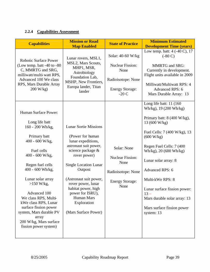
8/25/2005 Capability Roadmap Report Page 39
2.2.4 Capabilities Assessment
Capabilities Mission or Road Map Enabled
State of Practice Minimum Estimated Development Time (years)
Robotic Surface Power (Low temp. batt -40 to -80
C, MMRTG and SRG, milliwatt/multi-watt RPS, Advanced 100 We class
RPS, Mars Durable Array 200 W/kg)
Lunar rovers, MSL1, MSL2, Mars Scouts,
MHP1, MSR, Astrobiology
Foundation Lab, MSHP, New Frontiers, Europa lander, Titan
lander
Solar: 40-60 W/kg
Nuclear Fission: None
Radioisotope: None
Energy Storage:
-20 C
Low temp. batt: 4 (-40 C), 17 (-80 C)
MMRTG and SRG:
Currently in development. Flight units available in 2009
Milliwatt/Multiwatt RPS: 4
Advanced RPS: 6 Mars Durable Array: 13
Human Surface Power:
Long life batt 160 - 200 Wh/kg,
Primary batt
400 - 600 W/kg,
Fuel cells 400 - 600 W/kg,
Regen fuel cells
400 - 600 Wh/kg,
Lunar solar array >150 W/kg,
Advanced 100
We class RPS, Multi- kWe class RPS, Lunar surface fission power
system, Mars durable PV array
200 W/kg, Mars surface fission power system)
Lunar Sortie Missions
(Power for human lunar expeditions,
astronaut suit power, science package &
rover power)
Single Location Lunar Outpost
(Astronaut suit power,
rover power, lunar habitat power, high power for ISRU),
Human Mars Exploration
(Mars Surface Power)
Solar: None
Nuclear Fission: None
Radioisotope: None
Energy Storage:
None
Long life batt: 11 (160 Wh/kg), 19 (200 Wh/kg) Primary batt: 8 (400 W/kg), 13 (600 W/kg) Fuel Cells: 7 (400 W/kg), 13 (600 W/kg) Regen Fuel Cells: 7 (400 Wh/kg), 20 (600 Wh/kg) Lunar solar array: 8 Advanced RPS: 6 Multi-kWe RPS: 8 Lunar surface fission power: 13 – Mars durable solar array: 13 Mars surface fission power system: 13
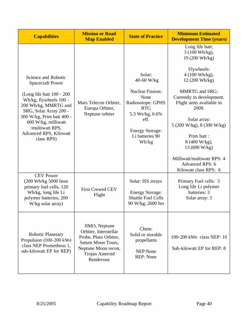
8/25/2005 Capability Roadmap Report Page 40
Capabilities Mission or Road Map Enabled State of Practice Minimum Estimated
Development Time (years)
Science and Robotic Spacecraft Power
(Long life batt 100 - 200 Wh/kg, flywheels 100 -
200 Wh/kg, MMRTG and SRG, Solar Array 200 -
300 W/kg, Prim batt 400 - 600 W/kg, milliwatt
/multiwatt RPS, Advanced RPS, Kilowatt
class RPS)
Mars Telecon Orbiter, Europa Orbiter, Neptune orbiter
Solar: 40-60 W/kg
Nuclear Fission:
None Radiosotope: GPHS
RTG 5.3 We/kg, 6.6%
eff.
Energy Storage: Li batteries 90
Wh/kg
Long life batt: 3 (100 Wh/kg), 19 (200 Wh/kg)
Flywheels:
4 (100 Wh/kg), 12 (200 Wh/kg)
MMRTG and SRG:
Currently in development. Flight units available in
2009.
Solar array: 5 (200 W/kg), 8 (300 W/kg)
Prim batt :
8 (400 W/kg), 13 (600 W/kg)
Milliwatt/multiwatt RPS: 4
Advanced RPS: 6 Kilowatt class RPS: 6
CEV Power (200 Wh/kg 5000 hour primary fuel cells, 120
Wh/kg, long life Li polymer batteries, 200
W/kg solar array)
First Crewed CEV Flight
Solar: ISS arrays
Energy Storage: Shuttle Fuel Cells 90 W/kg, 2600 hrs
Primary Fuel cells: 3 Long life Li polymer
batteries: 3 Solar array: 5
Robotic Planetary Propulsion (100-200 kWe class NEP Prometheus 1, sub-kilowatt EP for REP)
JIMO, Neptune Orbiter, Interstellar
Probe, Pluto Orbiter, Saturn Moon Tours,
Neptune Moon recon, Trojan Asteroid
Rendevous
Chem: Solid or storable
propellants
NEP:None REP: None
100-200 kWe class NEP: 10
Sub-kilowatt EP for REP: 8
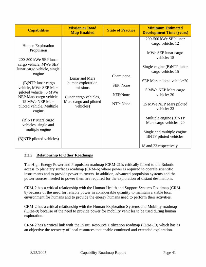
8/25/2005 Capability Roadmap Report Page 41
Capabilities Mission or Road Map Enabled State of Practice Minimum Estimated
Development Time (years)
Human Exploration Propulsion
200-500 kWe SEP lunar cargo vehicle, MWe SEP lunar cargo vehicle, single
engine
(B)NTP lunar cargo vehicle, MWe SEP Mars piloted vehicle, 5 MWe NEP Mars cargo vehicle,
15 MWe NEP Mars piloted vehicle, Multiple
engine
(B)NTP Mars cargo vehicles, single and
multiple engine
(B)NTP piloted vehicles)
Lunar and Mars human exploration
missions
(lunar cargo vehicles, Mars cargo and piloted
vehicles)
Chem:none
SEP: None
NEP:None
NTP: None
200-500 kWe SEP lunar cargo vehicle: 12
MWe SEP lunar cargo
vehicle: 18
Single engine (B)NTP lunar cargo vehicle: 15
SEP Mars piloted vehicle:20
5 MWe NEP Mars cargo
vehicle: 20
15 MWe NEP Mars piloted vehicle: 23
Multiple engine (B)NTP Mars cargo vehicles: 20
Single and multiple engine
BNTP piloted vehicles: 18 and 23 respectively
2.2.5 Relationship to Other Roadmaps The High Energy Power and Propulsion roadmap (CRM-2) is critically linked to the Robotic access to planetary surfaces roadmap (CRM-6) where power is required to operate scientific instruments and to provide power to rovers. In addition, advanced propulsion systems and the power sources needed to power them are required for the exploration of distant destinations. CRM-2 has a critical relationship with the Human Health and Support Systems Roadmap (CRM-8) because of the need for reliable power in considerable quantity to maintain a viable local environment for humans and to provide the energy humans need to perform their activities. CRM-2 has a critical relationship with the Human Exploration Systems and Mobility roadmap (CRM-9) because of the need to provide power for mobility vehic les to be used during human exploration. CRM-2 has a critical link with the In situ Resource Utilization roadmap (CRM-13) which has as an objective the recovery of local resources that enable continued and extended exploration.

8/25/2005 Capability Roadmap Report Page 42
Resource recovery is an energy intensive process and nuclear power is an excellent or even necessary way to provide this power. 2.2.6 Infrastructure Assessment
Generic – (Needed for all Nuclear Fission Systems) Facility Exists? Comment
Ground prototype testing
no Reactor test facilities in vacuum/environment chambers (possibly with cold walls)
Fuel fabrication process development labs and
fuel fabrication facilities
Limited (DOE & Industry)
DOE has some fabrication capability for UN and coated-particle carbide fuels
Industry has fabrication capability for low- and high-enriched UO2 fuels with Zr cladding
No fabrication capability exists for NTP composite or cermet fuels
Fuel and Material Irradiation
Limited (DOE and
Universities)
Thermal-spectrum irradiation capabilities exist within DOE and academia
No fast-spectrum irradiation capabilities exist in U.S. No facilities exist for prototypic NTP fuel irradiation
Fuels & Material Post Irradiation Evaluation
(PIE)
Yes (DOE)
DOE (INL and ORNL) has comprehensive PIE facilities that could be augmented to meet all envisioned testing
requirements
Thermal-hydraulic test loops
no Variety of loops required for code and design validation, component and sub-system testing.
I&C test beds no Validates instrumentation and control system design
Power conversion and heat rejection system
testing
Limited (NASA, DOE,
Industry)
Facilities required for stand-alone component testing and for testing of the PCS and HRS as an integrated component of
electrically-heated Engineering Development Units (EDUs).
Safety Testing Generally, no
Facilities for fuel ablation testing, over-power testing, fission product release testing, hydrodynamic impact testing, etc.
will be required
Physics Critical Limited – DOE
TA-18 facility @ LANL is being relocated to NTS and availability dates are unclear
Re-commissioning of ZPPR facility @ INL is possible * Note: There is some potential synergism between surface power test facility requirements and those for low-power NEP. Thus, dual-use facilities may be possible in several instances. However due to differences in temperatures, materials, coolants, fission energy spectrum, technologies, etc., there is very limited synergism between surface power, NTP, and MMW-NEP test facility functional requirements. Dedicated facilities would be required in most cases for these concepts.
8/25/2005 Capability Roadmap Report Page 43
NTP/BNTP – only
• Hot hydrogen test facilities for both un- irradiated and irradiated fuels and materials (do not exist)
• NTP engine test facility (does not exist) • Nuclear furnace might be required – particularly if non-NERVA-heritage fuel is
employed (does not exist) 2.3 Summary
The development of High Energy Power and Propulsion systems will enable many exciting new human and science missions in the future. In particular, the development of nuclear fission power and propulsion systems will enable long-stay human lunar and Mars exploration, and transport of humans to and from Mars. However, the long- lead times required to develop both the nuclear and non-nuclear technologies and components and their associated infrastructure development will present a major technical, programmatic, and budgetary challenge. These long lead times require that these technologies and system developments be started immediately so that the capabilities are available when required. Likewise, the development of future lightweight, highly efficient radioisotope power systems will enable many future robotic science missions to the surface of Mars, Europa, Titan, Venus, as well as other deep space probes. The use of radioisotope electric propulsion will enable a certain class of science missions to small planetary bodies (small moons and asteroids) as well as provides capability to visit multiple small body destinations. Reusable solar electric propulsion cargo tugs offer the potential of economic transfer of cargo to and from the Earth and moon and Mars. Finally batteries, fuel cells, and other advanced energy storage devices will be ubiquitous in all areas of human and science exploration, from powering astronauts and rovers, to providing critical power for planetary landers and nighttime or shadowed power in conjunction with solar power systems.
8/25/2005 Capability Roadmap Report Page 44
Acronym list BNTP CBS
Biomodal Nuclear Thermal Propulsion Capability Breakdown Structure
CEV Crew Exploration Vehicle EDS Earth Departure Stage EP Electric Propulsion GPHS General Purpose Heat Source HEP&P High Energy Power and Propulsion INL Idaho National Lab ISRU In-situ Resource Utilization JIMO Jupiter Icy Moon Obiter LSAM Lunar Surface Access Module MMRTG Multi Mission Radioisotope Thermoelectric Generator NEP Nuclear Electric Propulsion NERVA Nuclear Engine for Rocket Vehicle Applications MMW-NEP Multi Megawatt Nuclear Electric Propulsion NTP Nuclear Thermal Propulsion PIE Post Irradiation Evaluation PMAD Power Management and Distribution REP Radioisotope Electric Propulsion RPS Radioisotope Power System SEP Solar Electric Propulsion SRC Strategic Roadmap Committee SRG Stirling Radioisotope Generator TRL Technology Readiness Level

8/25/2005 Capability Roadmap Report Page 45
NASA
Capability Road Map (CRM) 3
In-Space Transportation (ISTP)
Executive Summary
Chair: Paul K. McConnaughey, NASA MSFC Co-Chair: Joseph Boyle, USAF SMC
Coordinators
Directorate
Betsy Park, NASA ESMD Gary Lyles, NASA ESMD Doug Craig, NASA ESMD
APIO
Tom Inman, NASA MSFC
Team Members:
NASA
John Connolly, NASA HQ Carol Covell, MSFC Jacobs Eng
Tim Crain, NASA JSC Brand Griffin, MSFC Gray Research
Ted Johnson, NASA LaRC Jesse Leitner, NASA GSFC Mike Meyer, NASA GRC
Russ Partch, AFRL VSE Shamim Rahman, NASA SSC
Ron Reeve, NASA JPL Rick Ryan, NASA MSFC Alan Sutton, AFRL PRSE Pete Vrotsos, NASA HQ
Mike Watson, NASA MSFC

8/25/2005 Capability Roadmap Report Page 46
3 In-Space Transportation (Roadmap 3) 3.1 General Capability Overview 3.1.1 Capability Description In-Space Transportation capability can broadly be defined as the ability to transport humans, cargo, and supporting infrastructure in space (beyond Low Earth Orbit (LEO)) to support the potential array of missions and applications for the Agency. The scope of In-Space Transportation capabilities planning, as defined in this study, was limited because several transportation capability areas were assigned to other capability roadmap teams (i.e., High Energy Propulsion and Power, Human Planetary Landing Systems, etc). Consequently, the general scope of the In-Space Transportation Capability Roadmap (IST CRM), in support the Vision for Space Exploration, includes only orbit-to-orbit transportation and in-space transfer. The IST CRM team collaborated with other capability roadmap teams at complimentary interfaces and areas of potential synergy (i.e. the launch vehicle upper stage, descent propulsion, planetary ascent, and docking/refueling mechanisms, aerocapture, autonomous vehicle mission management, and cryofluid management) to ensure consistency and completeness of the roadmap studies. The scope of the IST CRM study does not include human habitats, in-space assembly using humans or robotics, nuclear propulsion and high energy power (greater than 50 kilowatt (kW)), or entry, descent, and landing. Results from this capability study emphasize the need for technology advancement in the following areas: 1) in-space main and secondary propulsion, 2) cryofluid management, 3) autonomous rendezvous and docking (AR&D), 4) aerocapture, solar sails, and low-power electric propulsion (non-chemical propulsion), and 5) autonomous vehicle mission management (also known as the Vehicle Management System). This study treated the capability drivers as elements or stages of a transportation system or architecture, and the planning was consistent with the Agency exploration vision and science mission goals. 3.1.2 Benefits In-Space Transportation enables all Agency missions that require moving a payload or object in space. Since capabilities for basic in-space transportation already exist, the emphasis of this study was on identifying in-space transportation capabilities required to meet the challenging near-term as well as long-term goals and requirements of the Vision for Space Exploration that are not currently within the Nation’s capability. In-Space Transportation is one of the major cost drivers to affordably achieving these Exploration goals. Transportation requirements range from large, human-rated in-space vehicles to station-keeping for nano or micro-satellites and from small low-power electric thrusters to large solar sails capable of moving medium-sized science instruments. The benefits over existing or non-existent capabilities can be summarized as:
• Reliable transportation that enables future missions • Affordable transportation • Lower weight and cost for all vehicle subsystems
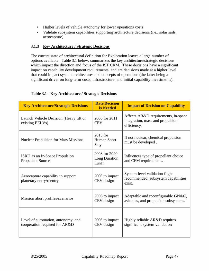
8/25/2005 Capability Roadmap Report Page 47
• Higher levels of vehicle autonomy for lower operations costs • Validate subsystem capabilities supporting architecture decisions (i.e., solar sails,
aerocapture)
3.1.3 Key Architecture / Strategic Decisions The current state of architectural definition for Exploration leaves a large number of options available. Table 3.1 below, summarizes the key architecture/strategic decisions which impact the direction and focus of the IST CRM. These decisions have a significant impact on capability development requirements, and are decisions made at a higher level that could impact system architectures and concepts of operations (the latter being a significant driver on long-term costs, infrastructure, and initial capability investments). Table 3.1 - Key Architecture / Strategic Decisions
Key Architecture/Strategic Decisions Date Decision is Needed Impact of Decision on Capability
Launch Vehicle Decision (Heavy lift or existing EELVs)
2006 for 2011 CEV
Affects AR&D requirements, in-space integration, mass and propulsion efficiency.
Nuclear Propulsion for Mars Missions 2015 for Human Short Stay
If not nuclear, chemical propulsion must be developed .
ISRU as an In-Space Propulsion Propellant Source
2008 for 2020 Long Duration Lunar
Influences type of propellant choice and CFM requirements.
Aerocapture capability to support planetary entry/reentry
2006 to impact CEV design
System-level validation flight recommended; subsystem capabilities exist.
Mission abort profiles/scenarios 2006 to impact CEV design
Adaptable and reconfigurable GN&C, avionics, and propulsion subsystems.
Level of automation, autonomy, and cooperation required for AR&D
2006 to impact CEV design
Highly reliable AR&D requires significant system validation.
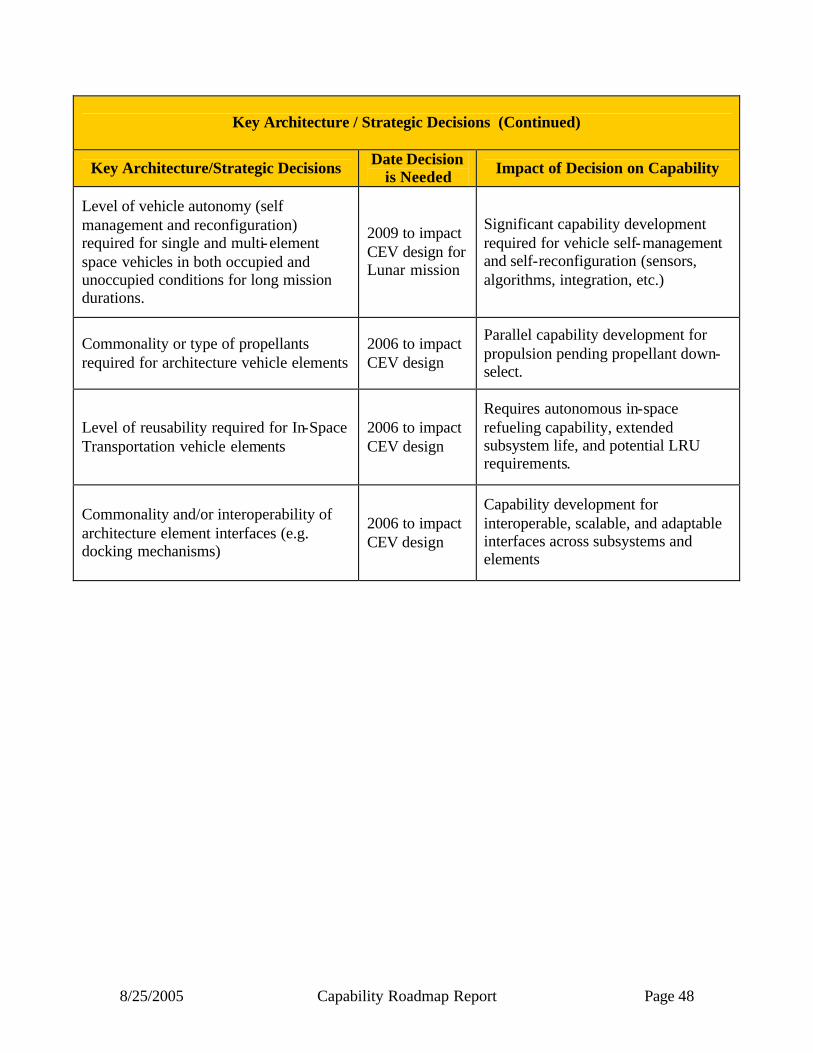
8/25/2005 Capability Roadmap Report Page 48
Key Architecture / Strategic Decisions (Continued)
Key Architecture/Strategic Decisions Date Decision is Needed Impact of Decision on Capability
Level of vehicle autonomy (self management and reconfiguration) required for single and multi-element space vehicles in both occupied and unoccupied conditions for long mission durations.
2009 to impact CEV design for Lunar mission
Significant capability development required for vehicle self-management and self-reconfiguration (sensors, algorithms, integration, etc.)
Commonality or type of propellants required for architecture vehicle elements
2006 to impact CEV design
Parallel capability development for propulsion pending propellant down-select.
Level of reusability required for In-Space Transportation vehicle elements
2006 to impact CEV design
Requires autonomous in-space refueling capability, extended subsystem life, and potential LRU requirements.
Commonality and/or interoperability of architecture element interfaces (e.g. docking mechanisms)
2006 to impact CEV design
Capability development for interoperable, scalable, and adaptable interfaces across subsystems and elements
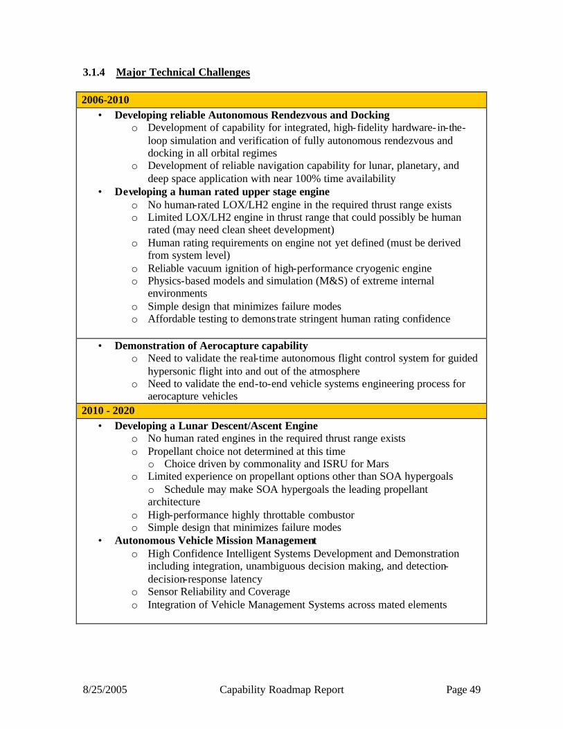
8/25/2005 Capability Roadmap Report Page 49
3.1.4 Major Technical Challenges 2006-2010
• Developing reliable Autonomous Rendezvous and Docking o Development of capability for integrated, high-fidelity hardware- in-the-
loop simulation and verification of fully autonomous rendezvous and docking in all orbital regimes
o Development of reliable navigation capability for lunar, planetary, and deep space application with near 100% time availability
• Developing a human rated upper stage engine o No human-rated LOX/LH2 engine in the required thrust range exists o Limited LOX/LH2 engine in thrust range that could possibly be human
rated (may need clean sheet development) o Human rating requirements on engine not yet defined (must be derived
from system level) o Reliable vacuum ignition of high-performance cryogenic engine o Physics-based models and simulation (M&S) of extreme internal
environments o Simple design that minimizes failure modes o Affordable testing to demons trate stringent human rating confidence
• Demonstration of Aerocapture capability
o Need to validate the real-time autonomous flight control system for guided hypersonic flight into and out of the atmosphere
o Need to validate the end-to-end vehicle systems engineering process for aerocapture vehicles
2010 - 2020 • Developing a Lunar Descent/Ascent Engine
o No human rated engines in the required thrust range exists o Propellant choice not determined at this time
o Choice driven by commonality and ISRU for Mars o Limited experience on propellant options other than SOA hypergoals
o Schedule may make SOA hypergoals the leading propellant architecture
o High-performance highly throttable combustor o Simple design that minimizes failure modes
• Autonomous Vehicle Mission Management o High Confidence Intelligent Systems Development and Demonstration
including integration, unambiguous decision making, and detection-decision-response latency
o Sensor Reliability and Coverage o Integration of Vehicle Management Systems across mated elements

8/25/2005 Capability Roadmap Report Page 50
• Long duration (90 days) cryofluid management o Development of a flight liquid hydrogen cryocooler (5-20 watts heat
removal) for eliminating boiloff o Acquisition and delivery of vapor-free liquid cryogenic propellant in a
low-g or omni-g environment for propulsion and transfer • High performance, low cost, long life solar electric propulsion
o Increase life by achieving a four fold increase in total impulse compared with the NSTAR thruster
o Reduce SEP system costs by a factor of two compared with SOA (Dawn) o Increase the specific impulse from NSTAR’s 3100 seconds to the 5000
seconds future missions more challenging needs • Developing Precision Propulsion capability
o Absolutely required to enable Universe interferometers and telescopes o Need to develop and life test ultra-high precision propulsion with
unprecedented stability, noise, lifetime, and plume contamination control as much as 1,000-fold better than SOA
• Long life components and subsystems o Long stay lunar and Mars missions drive life from seconds to hours and
weeks to year o Example – Chemical EDS Main Engine to Mars: SOA is about 600 sec
operating time. Goes to approximately one hour. o Long life space compatible components o Flight cryocooler for liquid hydrogen must operate continuously for up to
one year (lunar missions) and many years for Human Mars and some Science missions without failure
2020 and Beyond • Advanced Autonomous Vehicle Mission Management
o Reconfiguration and Modularity of Vehicle Management Systems at the component level
o Vehicle Management Systems with awareness of vehicle states at the subcomponent level with responsiveness to previously unidentified faults
2010 – 2020 (continued from previous page)
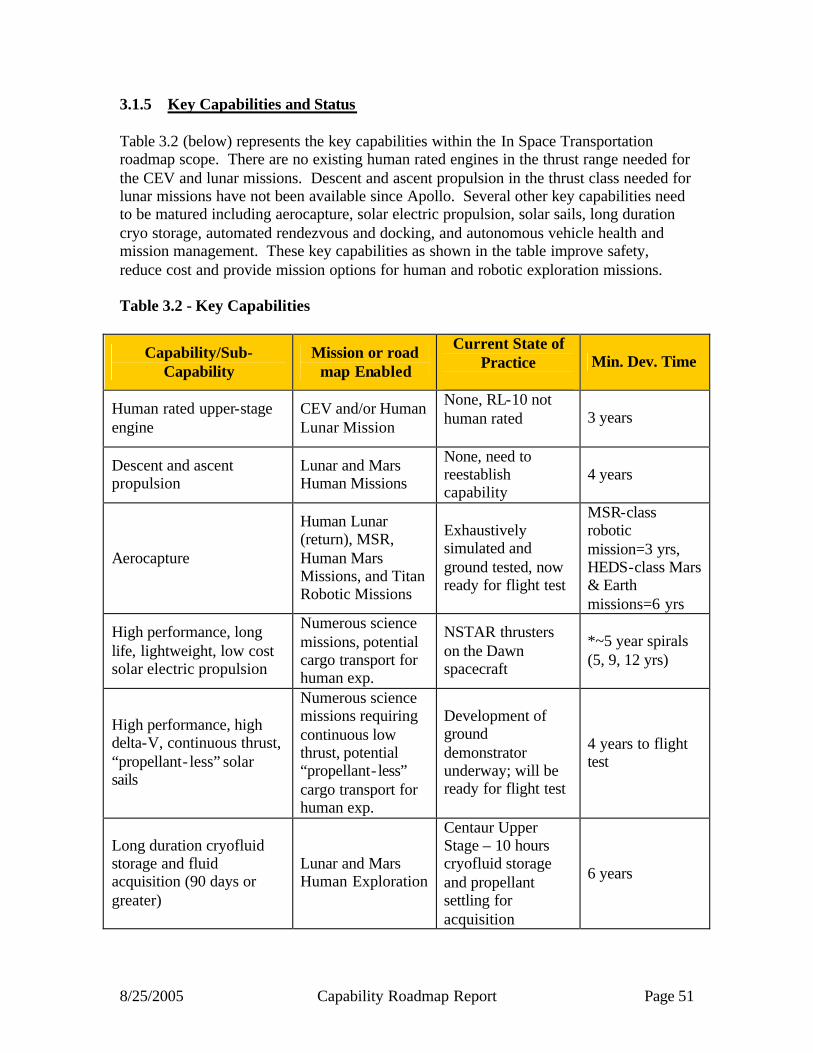
8/25/2005 Capability Roadmap Report Page 51
3.1.5 Key Capabilities and Status Table 3.2 (below) represents the key capabilities within the In Space Transportation roadmap scope. There are no existing human rated engines in the thrust range needed for the CEV and lunar missions. Descent and ascent propulsion in the thrust class needed for lunar missions have not been available since Apollo. Several other key capabilities need to be matured including aerocapture, solar electric propulsion, solar sails, long duration cryo storage, automated rendezvous and docking, and autonomous vehicle health and mission management. These key capabilities as shown in the table improve safety, reduce cost and provide mission options for human and robotic exploration missions. Table 3.2 - Key Capabilities
Capability/Sub-Capability
Mission or road map Enabled
Current State of Practice
Min. Dev. Time
Human rated upper-stage engine
CEV and/or Human Lunar Mission
None, RL-10 not human rated
3 years
Descent and ascent propulsion
Lunar and Mars Human Missions
None, need to reestablish capability
4 years
Aerocapture
Human Lunar (return), MSR, Human Mars Missions, and Titan Robotic Missions
Exhaustively simulated and ground tested, now ready for flight test
MSR-class robotic mission=3 yrs, HEDS-class Mars & Earth missions=6 yrs
High performance, long life, lightweight, low cost solar electric propulsion
Numerous science missions, potential cargo transport for human exp.
NSTAR thrusters on the Dawn spacecraft
*~5 year spirals (5, 9, 12 yrs)
High performance, high delta-V, continuous thrust, “propellant- less” solar sails
Numerous science missions requiring continuous low thrust, potential “propellant- less” cargo transport for human exp.
Development of ground demonstrator underway; will be ready for flight test
4 years to flight test
Long duration cryofluid storage and fluid acquisition (90 days or greater)
Lunar and Mars Human Exploration
Centaur Upper Stage – 10 hours cryofluid storage and propellant settling for acquisition
6 years

8/25/2005 Capability Roadmap Report Page 52
Reliable autonomous rendezvous and docking
Human Lunar, MSR, and Human Mars Missions
Russian Progress, DART, Orbital Express
4-8 yrs
Autonomous vehicle health and mission management
Lunar and Mars Human Missions
Ground-based Human Intelligence with automatic flight systems
10 yrs for full capability, 3-5 yrs for basic critical systems
Common and/or interoperable architecture element interfaces (e.g. docking and refueling mechanisms)
CEV and/or Human Lunar Mission
Russian Progress, ISS/STS interface 4-8 yrs
Table 3.3 shows representative in-space transportation capabilities at the state of the art (SOA), capability needs for the mid-term, and capability needs for the far-term Table 3.3 - Representative In-Space Transportation Capability Needs
Capability SOA
Near-Term Need
Long-Term Need
Chemical Engines Human Need Engine Burn Time (sec) No of Restarts
NA 450-600
2
Yes
450-600 2-3
Yes
3600-4000 5-8
Low Power SEP Isp (sec) Specific Mass (kg/kw) Total Impulse (MN-s)
3200 3.6 5
4200
2 10
7000
1 20
Cryo Fluid Management Passive Storage (%/month) Cryo Cooler (years storage without loss)
3 NA
1
6 months, LO2, CH4
0.5
5-10 years LH2
Cryo Tanks Metals/Alloys (Areal density in lbs/in3/ft)
0.1
0.085
0.07
AR&D Sensor Update Rate (cycle/sec) Reliability
5 to 25 Class C/D (DART)
25
Class A/B
100 Class A/B
Rad-Hardened

8/25/2005 Capability Roadmap Report Page 53
3.2 Roadmap Development 3.2.1 Legacy Activities and Roadmap Assumptions Legacy Activities The IST CRM Team utilized previous studies as much as possible in developing its plan for capabilities to support the Vision for Space Exploration. These studies included:
• Capability Roadmap Analysis and Integration (CRAI) studies • 120-Day Air Force/NASA Study • Space Launch Initiative (SLI) Planning studies and technology maturation results • Human and Robotics Technology (H&RT), intramural, and extramural awards
within NASA’s Exploration Systems Mission Directorate (ESMD) • In-Space Integrated Space Transportation Plan and the current In-Space
Propulsion Program content sponsored by the Science Mission Directorate • Available historical and currently available architecture studies
It is important to emphasize that although these study plans were not used verbatim, results were tailored or adapted as appropriate to the requirements, framework, and mission objectives of the current study. Where previous data was not available, new capability planning data was generated within the requirements and framework missions. Top Level Architectural Assumptions & Applications The architectural assumptions and missions/applications were consistent with the Advanced Planning and Integration Office (APIO) “framework” that encompassed both human and robotic components of the Vision for Space Exploration. These missions included:
• Lunar Roadmap Framework: Short Stay • Lunar Roadmap Framework: Long Stay • Lunar Design Reference Mission (DRM) TP2001 • Lunar Robotic Science DRM • Mars Roadmap Framework • Mars FY03 Nuclear Electric Propulsion (NEP) Architecture • Mars NASA Special Publication (SP) 2 • Mars NASA Special Publication (SP)-6107: “Human Exploration of Mars: The
Reference Mission of the NASA Mars Exploration Study Team.” • Mars Technical Publication 2002 • Mars Robotic Science DRM • Outer Solar System Science DRM • Advanced Science Observatories • Exploration Transportation System Roadmap Framework • ISS Roadmap Framework • Earth Science • Sun-Earth System Science

8/25/2005 Capability Roadmap Report Page 54
• Air Transportation Roadmap Framework • Nuclear System Roadmap Framework
In addition to these missions, others studies and mission plans that were used included the Concept Exploration and Refinement (CE&R) interim results led by ESMD and potential exploration missions. This was done to ensure that the capability planning covered a broad range of architectures. Other assumptions specific to the IST CRM planning included:
• Capability is broadly defined as pre-acquisition development from concept to test, with supporting infrastructure (tools, skills, and facilities),
• Where requirements were not defined, expert assessment of reasonable and/or probable options were assumed and assessed accordingly,
• Future capabilities will require improvements in “pervasive” technologies (e.g., materials, structures, design methods, etc.),
• The crew and cargo will be in separate launches, • Expendable systems and system elements will not have depot maintenance
(ground-based or International Space Station (ISS)), but elements of system may be multi-use and/or refuel-able,
• Minor non-depot maintenance (both automated and human) is expected, • The systems developed will require significant on-orbit integration, • The developed vehicle(s) will operate automated/autonomously when necessary, • Vehicle(s) and elements may have significant In-Space life requirements that
cycle between active and dormant states, and • Mars Exploration capability requirements feed back into capability planning for
earlier exploration efforts. Given the above representative architectures and missions, the IST CRM Team used the Crew Exploration Vehicle (CEV) requirements and plans for the competitive science missions to develop roadmaps that accounted for the range of potential In-Space capability needs. The net result was a requirements-driven capability plan, with the capabilities supporting both a focused human exploration plan and competitive science mission options. This IST CRM Plan was then compared to the results of the following Strategic Roadmap (SRM) interim reports:
• Robotic and Human Exploration of Mars Interim SRM Report • Solar System Exploration Interim SRM Report • Search for Earth- like Planets Interim SRM Report • Universe Exploration Interim SRM Report • Earth Science & Applications from Space Interim SRM Report • Sun-Solar System Connection Interim SRM Report • Solar System Exploration SRM feedback on IST CRM White Paper
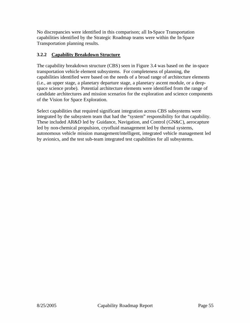
8/25/2005 Capability Roadmap Report Page 55
No discrepancies were identified in this comparison; all In-Space Transportation capabilities identified by the Strategic Roadmap teams were within the In-Space Transportation planning results. 3.2.2 Capability Breakdown Structure The capability breakdown structure (CBS) seen in Figure 3.4 was based on the in-space transportation vehicle element subsystems. For completeness of planning, the capabilities identified were based on the needs of a broad range of architecture elements (i.e., an upper stage, a planetary departure stage, a planetary ascent module, or a deep-space science probe). Potential architecture elements were identified from the range of candidate architectures and mission scenarios for the exploration and science components of the Vision for Space Exploration. Select capabilities that required significant integration across CBS subsystems were integrated by the subsystem team that had the “system” responsibility for that capability. These included AR&D led by Guidance, Navigation, and Control (GN&C), aerocapture led by non-chemical propulsion, cryofluid management led by thermal systems, autonomous vehicle mission management/intelligent, integrated vehicle management led by avionics, and the test sub-team integrated test capabilities for all subsystems.

8/25/2005 Capability Roadmap Report Page 56
Figure 3.4 – Capability Breakdown Structure

8/25/2005 Capability Roadmap Report Page 57
3.2.3 Roadmap Logic The capability roadmap in this report is a summary level roadmap. This summary level roadmap includes only a roll up of the key sub-capabilities milestone readiness to support a particular mission requirement. Detailed sub-capability and technology roadmaps showing the technology progression and sub-capability development were presented to the NAS and are available in the document sharing system. In the top blue banner of the roadmap, there are key missions that are pertinent to the CRM Planning Milestones Chart. The green banner below represents a summary rollup of key capabilities from each of the various capability breakdown structure elements. The peach colored swim-lanes represent the individual top level capability breakdown structure element and the sub-capabilities within this roadmap. The triangles represent the date that the capability is ready to support a given mission, and the diamonds represent decision points. The summary, In-Space Transportation Capability Roadmaps (IST CRMs) can be seen in Figures 3.5a and 3.5b. Figure 3.5a summarizes the high- level capabilities for the human exploration component of the Vision for Space Exploration, while Figure 3.5b addresses proposed science missions. For clarity, each is split into a 2005-2020 and 2020-2035 timeframe. The main conclusion of the roadmap supporting the Exploration capabilities in Figure 3.5a is that significant capability development should be started either immediately or in the very near-term timeframe to support the proposed mission milestones. Most capabilities for the lunar missions are developed in the 2005-2010 timeframe, while capabilities for the Mars missions are developed in the 2015 to 2020 timeframe. The majority of these capabilities are in the areas of chemical propulsion, thermal and structural systems, and GN&C/AR&D. The summary roadmap for capabilities specifically supporting the science missions can be seen in Figure 3.5b. The majority of the applicable capability development is in the area of non-chemical propulsion, and there is a need for tailoring of docking mechanisms and GN&C for some science missions. In the areas of chemical propulsion, structures, and thermal systems, it should be noted that the human exploration missions drive developments in those areas; it is expected that these developments will be used subsequently in later science mission applications. Also, due to the long term planning of the science missions, most capability areas should have an extended development in the 2020-2030 timeframe to support these missions. For more clarity and details of all of these roadmaps, the reader is referred to the In-Space Transportation Capability Roadmap NAS presentation.

8/25/2005 Capability Roadmap Report Page 58
3.1 Chemical Propulsion
3.2 Non-ChemicalPropulsion
3.3 Thermal Systems
3.4 Structures
3.5 GN&C / AR&D
3.6 Avionics
3.7 TVC, Docking and Sep. Systems
In-Space Transportation Capability Road Map(Key Events/Milestones)
2005 2010 20202015
Key Exploration Architectural Assumptions
3.8 Testing Capabilities
CEV Demo Uncrewed CEV Crewed CEV
Aerocapture Low L/D, MF= 25% at Mars
Lunar Spiral ILunar Spiral III & Mars
Lunar Spiral III & MarsOMS/RCS
CEV/Ascent/Descent Engines
CEV & LV US PDR EDS PDR CEV & EDS ISRU Upgrade PDR
Mars Chem EDS / ERS PDR
US/EDS Main Engine
CEV & LV US PDR EDS PDR CEV & EDS ISRU Upgrade PDR Mars Chem EDS / ERS PDR
Short DurationLunar
Long DurationLunar
TDS
Cryo Storage and CFM LH2 1 yr Storage LH2 many yrs Storage
Aerocapture TPS
Spacecraft Thermal Control
CEV TPSHuman Lunar TPS Upgrade
Advanced Active Control
Two Phase System
Develop advanced lifecycle testing and analysis toolsAdvanced material characterization of systemsMultifunctional Structures
Design, Analysis, & Validation
Upgrade of tanks Development of long-life tanks Mars mission tanksCryogenic TanksFuture development
Future development
Lifecycle testing
Vehicle System Reconfig.
Mission Analysis & Planning
Element-Element Integration Lunar
Aerocapture Low L/D, MF= 25% at Mars
Solar Sail Flight Demo
Aerocapture Flight Demo at Earth
CEV Veh.
CEV Int..
CEV Mission
Anal/Plan
Separation(Smart Init.)
Lunar Avionics
Continuous Test Capability for Propulsion, Structures, Thermal, Aerocapture, and other Subcapabilities
Human/Cargo Mars Integrated Structure
Navigation Absolute NavControl
Advanced Sensors, Algorithms, Physics-based dynamics toolsRelative Motion AnalysisRelative Nav
DistributedConnected
ContinuousNon-chemPropulsionImprovement
Lunar Spiral II
Aerocapture Flight Demo at Earth
Solar Sail Flight Demo
Capability Roadmaps: In-Space Transportation
TVC/EMA’s Docking MechanismResupply Mech.
Capability/Subcapability/Major Accomplishment
Capability/Subcapability/Demonstrated or
established
CRM Milestone/Mission
Major Decision
Range of Dates
Development Timelines
Legend
Capability/Subcapability/Major Accomplishment
Capability/Subcapability/Demonstrated or
established
CRM Milestone/Mission
Major Decision
Range of Dates
Development Timelines
Legend
Figure 3.5a – Capability Roadmap

8/25/2005 Capability Roadmap Report Page 59
3.2 Non-ChemicalPropulsion
3.3 Thermal Systems
3.4 Structures
3.5 GN&C / AR&D
3.6 Avionics
3.7 TVC, Docking and Sep. Systems
In-Space Transportation Capability Road Map(Key Events/Milestones)
2020 2025 20352030
Key Exploration Architectural Assumptions
3.8 Testing Capabilities
Long Duration Lunar203IT
Mars CargoMission 203x
Mars HumanMission
Aerocapture Mid L/D, MF= 25% at Mars
Solar Sail 100X Better
3.1 Chemical Propulsion
Human/Cargo Mars TPSAerocapture TPS
Future developmentFuture development
Lifecycle testingMultifunctional Structures
Design, Analysis, & Validation
Cryogenic Tanks
Aerocapture Mid L/DMF= 25% at Mars
Vehicle System Reconfig.
Mission Analysis & Planning
Element-Element Integration
Human/Cargo Mars TPS
Human/Cargo Mars IntegratedStructure
Mars Fly-by. Mars HumanLanding.
Extended AutonomousMission Capability.
Mars AutonomousMission Capability.
Continuous Test Capability for Propulsion, Structures, Thermal, Aerocapture, and other Subcapabilities
ContinuousNon-chemPropulsion
Improvement
Continuous ChemPropulsion
ImprovementAs Needed
Continuous GN&CImprovementAs Needed
ContinuousMechanism
ImprovementAs Needed
ContinuousThermal Sys.ImprovementAs Needed
Capability Roadmaps: In-Space Transportation
2020
Capability/Subcapability/Major Accomplishment
Capability/Subcapability/Demonstrated or
established
CRM Milestone/Mission
Major Decision
Range of Dates
Development Timelines
Legend
Capability/Subcapability/Major Accomplishment
Capability/Subcapability/Demonstrated or
established
CRM Milestone/Mission
Major Decision
Range of Dates
Development Timelines
Legend
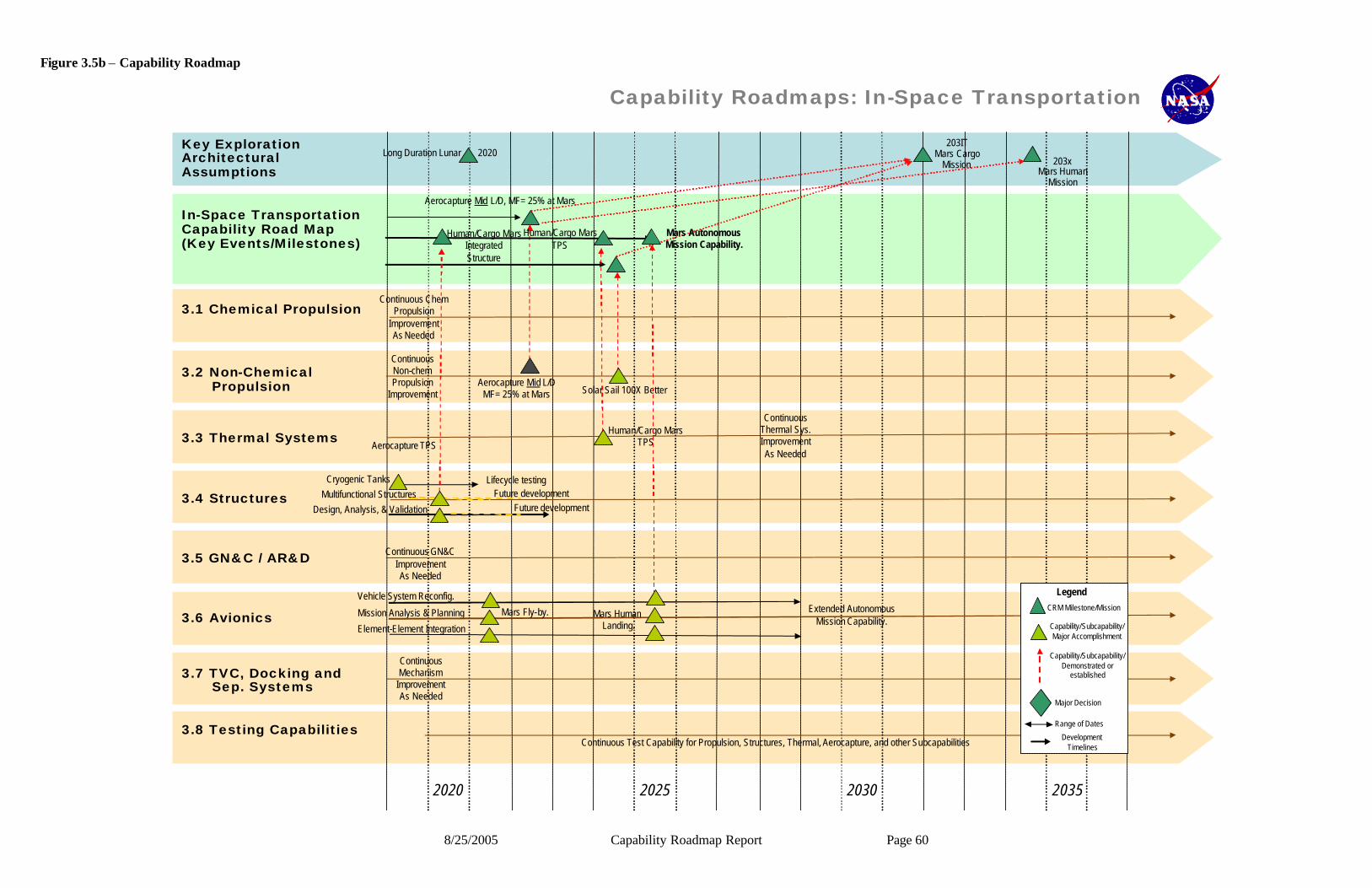
8/25/2005 Capability Roadmap Report Page 60
3.2 Non-ChemicalPropulsion
3.3 Thermal Systems
3.4 Structures
3.5 GN&C / AR&D
3.6 Avionics
3.7 TVC, Docking and Sep. Systems
In-Space Transportation Capability Road Map(Key Events/Milestones)
2020 2025 20352030
Key Exploration Architectural Assumptions
3.8 Testing Capabilities
Long Duration Lunar203IT
Mars CargoMission 203x
Mars HumanMission
Aerocapture Mid L/D, MF= 25% at Mars
Solar Sail 100X Better
3.1 Chemical Propulsion
Human/Cargo Mars TPSAerocapture TPS
Future developmentFuture development
Lifecycle testingMultifunctional Structures
Design, Analysis, & Validation
Cryogenic Tanks
Aerocapture Mid L/DMF= 25% at Mars
Vehicle System Reconfig.
Mission Analysis & Planning
Element-Element Integration
Human/Cargo Mars TPS
Human/Cargo Mars IntegratedStructure
Mars Fly-by. Mars HumanLanding.
Extended AutonomousMission Capability.
Mars AutonomousMission Capability.
Continuous Test Capability for Propulsion, Structures, Thermal, Aerocapture, and other Subcapabilities
ContinuousNon-chemPropulsion
Improvement
Continuous ChemPropulsion
ImprovementAs Needed
Continuous GN&CImprovementAs Needed
ContinuousMechanism
ImprovementAs Needed
ContinuousThermal Sys.ImprovementAs Needed
Capability Roadmaps: In-Space Transportation
2020
Capability/Subcapability/Major Accomplishment
Capability/Subcapability/Demonstrated or
established
CRM Milestone/Mission
Major Decision
Range of Dates
Development Timelines
Legend
Capability/Subcapability/Major Accomplishment
Capability/Subcapability/Demonstrated or
established
CRM Milestone/Mission
Major Decision
Range of Dates
Development Timelines
Legend
Figure 3.5b – Capability Roadmap
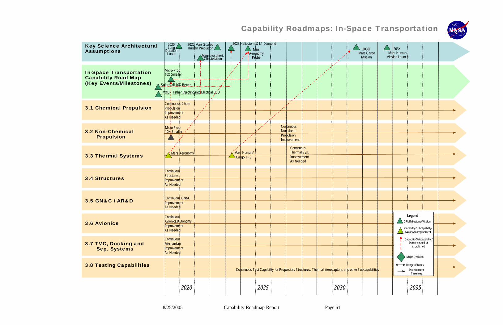
8/25/2005 Capability Roadmap Report Page 61
3.2 Non-ChemicalPropulsion
3.3 Thermal Systems
3.4 Structures
3.5 GN&C / AR&D
3.6 Avionics
3.7 TVC, Docking and Sep. Systems
In-Space Transportation Capability Road Map(Key Events/Milestones)
2020 2025 20352030
Key Science Architectural Assumptions
3.8 Testing Capabilities
Magnetospheric Constellation
MXER Tether Injecting into Elliptical LEO
Mars Aeronomy
Probe
Solar Sail 10X Better
Micro-Prop 10X Smaller
2020Long
Duration Lunar
3.1 Chemical Propulsion
2022 Mars ScaledHuman Precursor
2023 Heliostorm & L1 Diamond
Mars Aeronomy Mars Human/ Cargo TPS
203ITMars Cargo
Mission
Micro-Prop 10X Smaller
Continuous Test Capability for Propulsion, Structures, Thermal, Aerocapture, and other Subcapabilities
ContinuousNon-chemPropulsionImprovement
Continuous ChemPropulsionImprovementAs Needed
Continuous GN&CImprovementAs Needed
ContinuousMechanismImprovementAs Needed
ContinuousThermal Sys.ImprovementAs Needed
ContinuousAvionics/AutonomyImprovementAs Needed
ContinuousStructuresImprovementAs Needed
Capability Roadmaps: In-Space Transportation
203XMars Human
Mission Launch
Capability/Subcapability/Major Accomplishment
Capability/Subcapability/Demonstrated or
established
CRM Milestone/Mission
Major Decision
Range of Dates
Development Timelines
Legend
Capability/Subcapability/Major Accomplishment
Capability/Subcapability/Demonstrated or
established
CRM Milestone/Mission
Major Decision
Range of Dates
Development Timelines
Legend
8/25/2005 Capability Roadmap Report Page 62
3.2.4 Capabilities Assessment The table 3.4 describes the high- level capabilities seen in Figures 3.5a and 3.5b. The necessary capability is described (and sometimes broken down in more detail) and is tied to the CBS number used in the roadmaps. An initial needed date (in terms of capability need) is noted, with potential application to a broader range of missions. An example of this would be a need for the first lunar sortie missions that would also apply to later robotic science missions of human Mars missions. The current state-of-practice is referenced, along with an estimated capability development time. A range in the latter results from potential variation in architecture requirements and expanded mission capability needs over time.

8/25/2005 Capability Roadmap Report Page 63
Table 3.4 - Current State of Practice of Capabilities
Current State of Practice of Capabilities
Capabilities (CBS, Year
Needed from Exp. or Sci. Roadmap)
Mission or Road Map Enabled
State of Practice:
Minimum estimated
Development Time
(can be a range)
Human-rated upper & earth departure stages main engines (3.1, 2008)
All human exploration missions
No human rated engines exist in the required thrust range. Some expendable cargo only engines exist that may be modified to meet requirements
3 years
Human-rated CEV/Lander/ Ascent main engines (3.1, 2008)
All human exploration missions
No human rated engines exist in the required thrust range. Current propellant SoP is using storable hypergolic propellants. Desire is for cryogenic ISRU potential propellants. Limited technology experience with candidates.
4 years
Human-rated cryogenic propellant based Reaction Control Systems (3.1, 2007)
All human exploration missions. Many science missions requiring higher performance chemical propulsion.
Current propellant SoP is using storable hypergolic propellants. Desire is for cryogenic ISRU potential propellants. Limited technology experience with candidates.
4 years
Large thrust LOX/LH2 cargo LV upper stage main engine (3.1, 2011)
All human exploration missions. Many science missions requiring heavy ETO lift capability.
Current USofA SoP is a small 25 klbf class engine. Larger engines in the desired thrust class exist from foreign sources. An old USofA design from the Apollo Saturn launch vehicle exist and could be redeveloped.
3 years
Vehicle State Determination (3.6, 2012)
Mars and Lunar Human Mission, Numerous Science Missions
Approximately 50% of the vehicle state is measured. Diagnostics are done primarily on the ground (X-34 demonstrated 5% of vehicle). Prognostics have been defined but not developed or demonstrated. State V&V has not been done onboard before and requires definition, development, and demonstration
5-10 years
DIaK Transport, Integration, and Processing (3.6, 2012)
Mars and Lunar Human Mission, Numerous Science Missions
Current data transport (MIL-STD-1553) is not capable of transporting data from large numbers of sensors or high frequency sensors. Radiation Hardened processors are limited to 300 MHz.
4-7 years
Mission Analysis and Planning (3.6, 2012)
Mars and Lunar Human Mission, Numerous Science Missions
Human based on the ground for ISS, Shuttle, probes, robotic missions, etc. 5-10 years
Vehicle System Reconfiguration (3.6, 2011)
Mars and Lunar Human Mission, Numerous Science Missions
Similar redundancy only. Systems are designed as monolithic with no modularity or reconfiguration capabilities
7-15 years
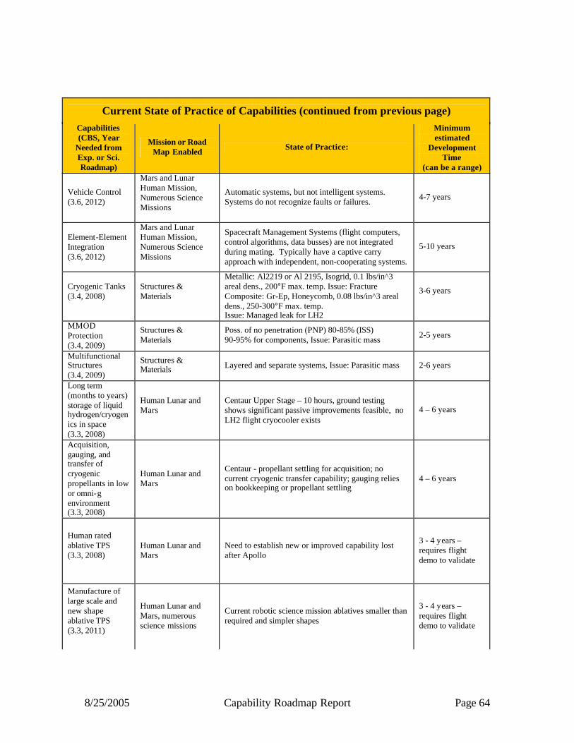
8/25/2005 Capability Roadmap Report Page 64
Capabilities (CBS, Year
Needed from Exp. or Sci. Roadmap)
Mission or Road Map Enabled State of Practice:
Minimum estimated
Development Time
(can be a range)
Vehicle Control (3.6, 2012)
Mars and Lunar Human Mission, Numerous Science Missions
Automatic systems, but not intelligent systems. Systems do not recognize faults or failures. 4-7 years
Element-Element Integration (3.6, 2012)
Mars and Lunar Human Mission, Numerous Science Missions
Spacecraft Management Systems (flight computers, control algorithms, data busses) are not integrated during mating. Typically have a captive carry approach with independent, non-cooperating systems.
5-10 years
Cryogenic Tanks (3.4, 2008)
Structures & Materials
Metallic: Al2219 or Al 2195, Isogrid, 0.1 lbs/in^3 areal dens., 200°F max. temp. Issue: Fracture Composite: Gr-Ep, Honeycomb, 0.08 lbs/in^3 areal dens., 250-300°F max. temp. Issue: Managed leak for LH2
3-6 years
MMOD Protection (3.4, 2009)
Structures & Materials
Poss. of no penetration (PNP) 80-85% (ISS) 90-95% for components, Issue: Parasitic mass 2-5 years
Multifunctional Structures (3.4, 2009)
Structures & Materials Layered and separate systems, Issue: Parasitic mass 2-6 years
Long term (months to years) storage of liquid hydrogen/cryogenics in space (3.3, 2008)
Human Lunar and Mars
Centaur Upper Stage – 10 hours, ground testing shows significant passive improvements feasible, no LH2 flight cryocooler exists
4 – 6 years
Acquisition, gauging, and transfer of cryogenic propellants in low or omni-g environment (3.3, 2008)
Human Lunar and Mars
Centaur - propellant settling for acquisition; no current cryogenic transfer capability; gauging relies on bookkeeping or propellant settling
4 – 6 years
Human rated ablative TPS (3.3, 2008)
Human Lunar and Mars
Need to establish new or improved capability lost after Apollo
3 - 4 years – requires flight demo to validate
Manufacture of large scale and new shape ablative TPS (3.3, 2011)
Human Lunar and Mars, numerous science missions
Current robotic science mission ablatives smaller than required and simpler shapes
3 - 4 years – requires flight demo to validate
Current State of Practice of Capabilities (continued from previous page)
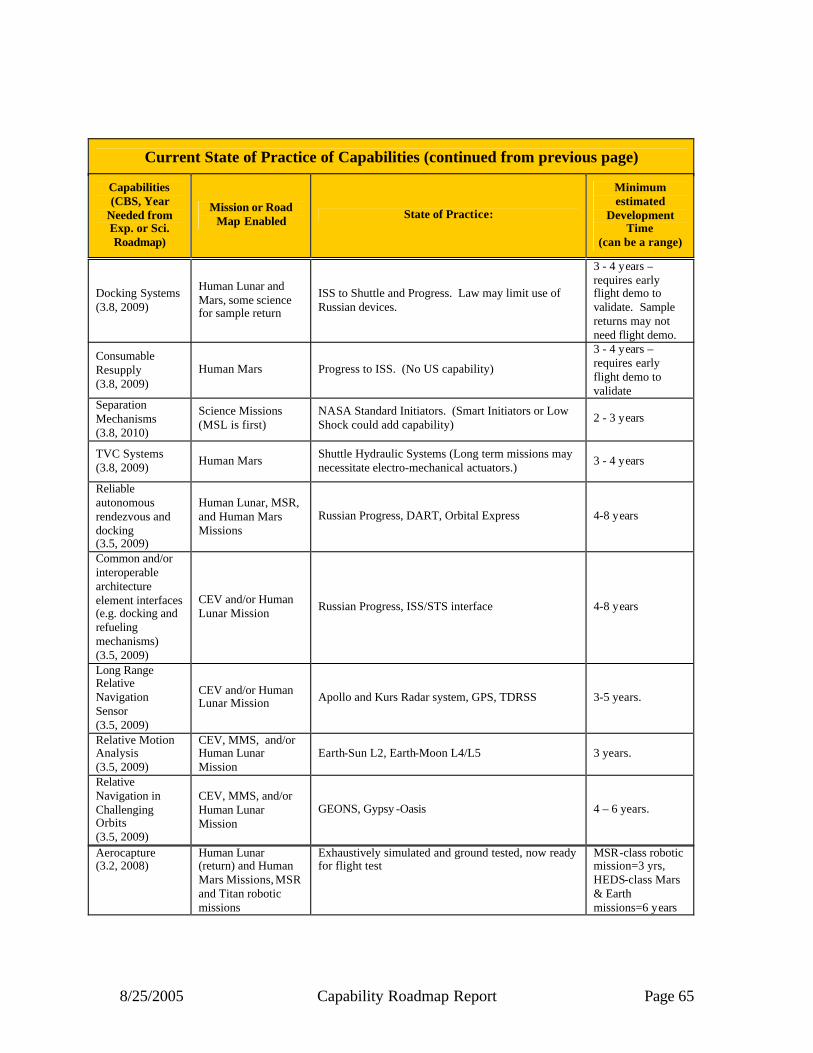
8/25/2005 Capability Roadmap Report Page 65
Aerocapture (3.2, 2008)
Human Lunar (return) and Human Mars Missions, MSR and Titan robotic missions
Exhaustively simulated and ground tested, now ready for flight test
MSR-class robotic mission=3 yrs, HEDS-class Mars & Earth missions=6 years
Current State of Practice of Capabilities (continued from previous page)
Capabilities (CBS, Year
Needed from Exp. or Sci. Roadmap)
Mission or Road Map Enabled State of Practice:
Minimum estimated
Development Time
(can be a range)
Docking Systems (3.8, 2009)
Human Lunar and Mars, some science for sample return
ISS to Shuttle and Progress. Law may limit use of Russian devices.
3 - 4 years – requires early flight demo to validate. Sample returns may not need flight demo.
Consumable Resupply (3.8, 2009)
Human Mars Progress to ISS. (No US capability)
3 - 4 years – requires early flight demo to validate
Separation Mechanisms (3.8, 2010)
Science Missions (MSL is first)
NASA Standard Initiators. (Smart Initiators or Low Shock could add capability) 2 - 3 years
TVC Systems (3.8, 2009) Human Mars Shuttle Hydraulic Systems (Long term missions may
necessitate electro-mechanical actuators.) 3 - 4 years
Reliable autonomous rendezvous and docking (3.5, 2009)
Human Lunar, MSR, and Human Mars Missions
Russian Progress, DART, Orbital Express 4-8 years
Common and/or interoperable architecture element interfaces (e.g. docking and refueling mechanisms) (3.5, 2009)
CEV and/or Human Lunar Mission Russian Progress, ISS/STS interface 4-8 years
Long Range Relative Navigation Sensor (3.5, 2009)
CEV and/or Human Lunar Mission Apollo and Kurs Radar system, GPS, TDRSS 3-5 years.
Relative Motion Analysis (3.5, 2009)
CEV, MMS, and/or Human Lunar Mission
Earth-Sun L2, Earth-Moon L4/L5 3 years.
Relative Navigation in Challenging Orbits (3.5, 2009)
CEV, MMS, and/or Human Lunar Mission
GEONS, Gypsy -Oasis 4 – 6 years.

8/25/2005 Capability Roadmap Report Page 66
3.2.5 Infrastructure Assessment The In-Space Transportation forecast for capability maturation was examined with respect to key enabling test capability, with a focus on that which supports human exploration missions. In doing so, a database of existing test facilities was assembled (building on earlier work) and is provided with the National Research Council (NRC) information package. Over 100 specific test facilities were identified for their likely or potential applicability to the various element s of IST CRM roadmaps (structures, propulsion, and so forth). The facilities are located all over the nation, and include world class test infrastructure within NASA, other government agencies (primarily Department of Defense (DoD)), and the aerospace private sector. For the most part, the current and heritage facilities are available to support IST ground test needs for human exploration missions, and are known to be either in active or inactive status. For the foreseeable future, it should be possible to largely utilize existing test facilities, generally by adapting, modifying, upgrading, and augmenting them to suit the particular capability development objectives. Test capability will need to be reassessed at major architecture decisions points in order to maintain a reasonably current status of facility applicability, availability, and readiness.
Current State of Practice of Capabilities (continued from previous page)
Capabilities (CBS, Year
Needed from Exp. or Sci. Roadmap)
Mission or Road Map Enabled State of Practice:
Minimum estimated
Development Time
(can be a range) High performance, long life, lightweight, low cost solar electric propulsion (SEP) (3.2, 2009)
Numerous science missions, potential cargo transport for human exp.
NSTAR thrusters on the DS-1 and Dawn spacecraft *~5 year spirals (5, 9, 12 years)
High performance, long life, lightweight, radioisotope electric propulsion (REP) (3.2, 2010)
Comet, asteroid, and outer planet science missions
8-cm and 20-cm ion engines under development 5 years
High performance, high delta-V, continuous thrust, “propellantless” solar sails (3.2, 2009)
Numerous science missions requiring continuous low thrust, potential “propellantless” cargo transport for human exp.
Development of ground demonstrator underway; will be ready for flight test
4 years to flight test
Ultra-high precision and micro-component propulsion (3.2, 2015)
Precision: Absolutely enabling for Universe/Origins interferometers and telescopes; Micro: Sun-Earth Small/Micro/Nano-satellites
Colloid thruster under development for LISA, miniature Xe-ion thruster under development for TPF-I; micro/low-power thrusters and valves under development for micro-spacecraft
10 years

8/25/2005 Capability Roadmap Report Page 67
3.3 Summary The IST CRM team studied the requirements, mission options, and goals for the Vision for Space Exploration and developed capability needs based on program requirements, mission options, schedules, and potential architectures. This study identified advancements for in-space transportation required to support long duration missions, on-orbit integration, common and/or interoperable element interfaces, high performance, high reliability, and lightweight subsystems. To meet these goals, capability developments in autonomous rendezvous and docking (AR&D), chemical propulsion (human rated upper stage, descent and ascent propulsion, etc.), cyrofluid management (low boil-off & zero-g acquisition), non-chemical propulsion (aerocapture and high performance, high delta-V continuous thrust propulsion methods), and autonomous vehicle health and mission management are required along with advances in more pervasive technologies such lightweight structures, materials, spacecraft thermal management and avionics.

8/25/2005 Capability Roadmap Report Page 68
Acronym List AFRL Air Force Research Laboratory AR&D Autonomous Rendezvous and Docking APIO Advanced Planning and Integration Office
CBS Capability Breakdown Structure CE&R Concept Exploration and Refinement CEV Crew Exploration Vehicle
CFM Cryogenic Fluid Management CRAI Capability Roadmap Analysis and Integration CRM Capability Roadmap
DART Demonstration for Autonomous Rendezvous Technology DIaK Data Information and Knowledge DoD Department of Defense
DRM Design Reference Mission DS-1 DV
Deep Space – 1 Delta Velocity
EDS Earth Departure Stage EELV Evolved Expendable Launch Vehicle ESMD Exploration Systems Mission Directorate
ETO Earth to Orbit GEONS GPS-Enhanced On-board Navigation System GN&C Guidance, Navigation, and Control
GPS Global Positioning System Gr-Ep Graphite-Epoxy GRC Glenn Research Center
GSFC Goddard Space Flight Center H2 HEDS
Hydrogen Human Exploration and Development of Space
HQ Headquarters H&RT Human and Robotics Technology IMLEO
ISRU
Injected Mass in Low Earth Orbit
In-Situ Resource Utilization ISS International Space Station IST In-Space Transportation
JPL Jet Propulsion Laboratory JSC Johnson Space Center Kurs Russian Docking System
kW Kilowatt LaRC Langley Research Center LEO Low Earth Orbit
LISA Large Isotope Spectrometer for Astromag LOX/LH2 Liquid Oxygen/Liquid Hydrogen
8/25/2005 Capability Roadmap Report Page 69
LRU Line Replaceable Unit LV Launch Vehicle
LSAM Lunar Surface Access Module LSE Lead Systems Engineer MDA Milestone Decision Authority
MHz Megahertz MIL-STD Military Standard MMOD Micrometeoroid Orbital Debris
MMS Magnetospheric Multiscale MOI M&S
Mars Orbit Injection Models and Simulation
MSFC Marshall Space Flight Center MSL Mars Surface Lander MSR Mars Sample Return
NEP Nuclear Electric Propulsion NRC National Research Council NSTAR NASA Solar Electric Propulsion Technology Application Readiness
PNP Possibility of No Penetration PRSE Propulsion Systems Research Engineering SMC Space and Missile Systems Center
SOA State-of-the-Art SoP State of Practice SP Special Publication
SRM Strategic Roadmap STS Space Transportation System TDRSS Tracking and Data Relay Satellite System
TPS Thermal Protection System TVC Thrust Vector Control USAF United States Air Force
US of A United States of America V&V Verification and Validation Xe
ZBO
Xenon
Zero Boiloff

8/25/2005 Capability Roadmap Report Page 70
NASA
Capability Road Map (CRM) 4
Advanced Telescope and Observatory (ATO)
Executive Summary
Chair: Lee Feinberg, NASA/GSFC
Co-Chair: Howard MacEwen, SRS Technologies
Coordinators
Directorate
Harley Thronson NASA SMD Giulio Varsi, NASA SMD
APIO
Dan Coulter, NASA JPL
Team Members
NASA / JPL / DOE
Phil Stahl, NASA MSFC
Jim Breckinridge, NASA JPL Peter Jones, DoD AFRL
Academia
Jim Burge University of Arizona Jim Fienup, University of Rochester
Dave Miller, MIT Dan Inman, Virginia Tech
Industry
Gary Matthews, ITT Mark Stier, Goodrich
Jim Oschmann, Ball Aerospace Jim Crocker, Lockheed
Ron Polidan, NGST

8/25/2005 Capability Roadmap Report Page 71
4 Advanced Telescope and Observatory (Roadmap 4) 4.1 General Capability Overview 4.1.1 Capability Description The Advanced Telescopes and Observatories (ATO) capability roadmap includes technologies necessary to enable future space telescopes and observatories collecting all electromagnetic bands, ranging from x-rays to millimeter waves, and including gravity-waves. It has derived capability priorities from the current and developing Science Mission Directorate (SMD) strategic roadmaps and, where appropriate, has ensured their consistency with other NASA strategic and capability roadmaps. The team collaborated closely with the Scientific Instruments and Sensors Roadmap team, which had the responsibility to address technologies associated with the detection, conversion, and processing of observed signals into data. In cooperation with the necessary science instruments, future space telescope technologies provide key enabling capabilities for four strategic roadmap (SR) areas:
• Searches for Earth- like planets and habitable environments around other stars. (SR4) • Exploration of the universe to understand its origin, structure, evolution, and destiny.
(SR8) • Earth Science (SR9) • Sun-Solar System Science (SR10)
In addition, Advanced Telescope and Observatory technology developed for NASA is synergistic with needs of several other government agencies ranging from DoD and the NRO to DoE. This roadmap has been developed with full participation of representatives from those agencies and appropriate synergisms, partnerships, and leveraging opportunities have been identified. The transition from the current set of on-orbit great observatories to the future suite of Advanced Telescopes and Observatories is shown in Figure 4.1. Currently, the Hubble Space Telescope (HST), Spitzer Space Telescope and Chandra X-ray Telescope are operational observatories and represent the state-of-the-art in advanced telescopes. However, the James Webb Space Telescope and Space Interferometer Mission are due for launch in the next decade, and require new technologies in lightweight optics, wavefront sensing and control, and precision metrology. Follow-on missions, such as the Terrestrial Planet Finder Coronagraph (TPF C), Constellation-X (Con X), and Single Aperture Far-Infrared telescope (SAFIR), will further advance capabilities in mirror technology, wavefront sensing and control, and cryogenic thermal control systems in a logical sequence. Longer-term missions will then add formation flying and more advanced imaging techniques (interferometric in some cases) to increase the effective aperture size. As shown in Figure 4.2, the vantage points for future observatories depend on the desired science. In the case of Universe and Search for Earth-like Planets, the overwhelming favorite vantage point is the Sun-Earth L2 (the current location of WMAP and planned orbit for JWST).

8/25/2005 Capability Roadmap Report Page 72
L2 provides a stable thermal environment, simple operational scenarios for communications and attitude correction, and a large unobscured view of the universe.
Figure 4.1: The transition from the current set of operating Great Observatories to the future suite of Advanced Telescopes and Observatories.
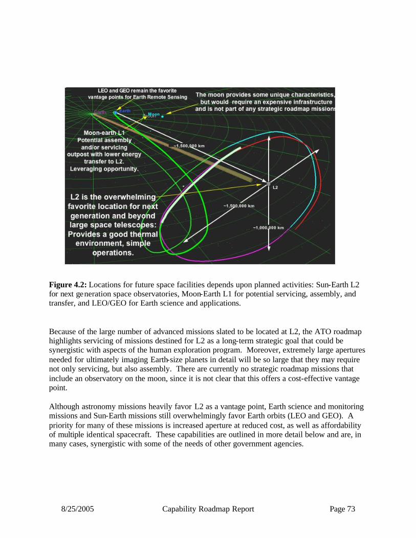
8/25/2005 Capability Roadmap Report Page 73
Figure 4.2: Locations for future space facilities depends upon planned activities: Sun-Earth L2 for next generation space observatories, Moon-Earth L1 for potential servicing, assembly, and transfer, and LEO/GEO for Earth science and applications. Because of the large number of advanced missions slated to be located at L2, the ATO roadmap highlights servicing of missions destined for L2 as a long-term strategic goal that could be synergistic with aspects of the human exploration program. Moreover, extremely large apertures needed for ultimately imaging Earth-size planets in detail will be so large that they may require not only servicing, but also assembly. There are currently no strategic roadmap missions that include an observatory on the moon, since it is not clear that this offers a cost-effective vantage point. Although astronomy missions heavily favor L2 as a vantage point, Earth science and monitoring missions and Sun-Earth missions still overwhelmingly favor Earth orbits (LEO and GEO). A priority for many of these missions is increased aperture at reduced cost, as well as affordability of multiple identical spacecraft. These capabilities are outlined in more detail below and are, in many cases, synergistic with some of the needs of other government agencies.

8/25/2005 Capability Roadmap Report Page 74
4.1.2 Benefits Development of these capabilities is necessary to enable systems for Earth science and applications and astronomical observatories. In turn, these future facilities will achieve the priority goals identified in the Vision for Space Exploration and numerous National Academy of Sciences decade reviews and recommendations. 4.1.3 Key Architecture / Strategic Decisions
Key Architecture/ Strategic Decisions
Date Decision is
Needed Impact of Decision on Capability
NASA decides to fund new heavy lift launch vehicle, which enables larger space observatories
2008 (TPF-C)
Larger shrouds and/or lower cost/mass launch vehicles could enable larger apertures.
NASA decides to work with other government agencies to Build/modify large optics test facilities for multiple missions
2008 (TPF-C)
System level ground tests are expensive and complex and JWST is stressing limits of available facilities. NASA needs to decide whether to leverage the JWST test facility for future missions (TPFC, SAFIR) or whether to build a new facility that can also serve other national interests.
Decision to sustain and expand NASA’s on-orbit assembly and servicing capability to achieve multiple priority objectives, including large optical systems
Libration mission servicing: 2010 (SAFIR), Libration mission assembly: 2015 (LF)
Enables extended lifetime missions with greater performance and lower risk. Common systems provide resources for on-orbit assembly, repair, servicing, and may be a capability for sustaining space operations experience. Assembled systems enable larger size and mass telescopes. Need to make decision early enough to affect observatory architecture. SAFIR is initial candidate for servicing. LF is candidate for assembly.
Decision to jointly invest with other agencies in major large optics technology capabilities
2006/2007
Allows a leveraging of available funding to develop new technologies including replicated optics, active wavefront sensing and control systems, and low cost 3-meter class telescopes. Could enable future Earth and other science missions at lower cost and also help serve national secur ity interests. Builds upon the heritage of joint investments among NASA, NRO and AFRL on lightweight mirror technology for JWST and other applications.
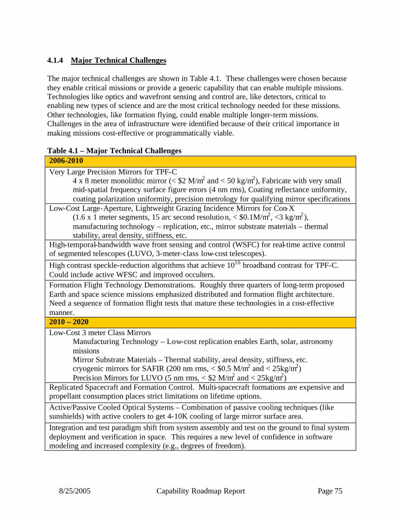
8/25/2005 Capability Roadmap Report Page 75
4.1.4 Major Technical Challenges The major technical challenges are shown in Table 4.1. These challenges were chosen because they enable critical missions or provide a generic capability that can enable multiple missions. Technologies like optics and wavefront sensing and control are, like detectors, critical to enabling new types of science and are the most critical technology needed for these missions. Other technologies, like formation flying, could enable multiple longer-term missions. Challenges in the area of infrastructure were identified because of their critical importance in making missions cost-effective or programmatically viable. Table 4.1 – Major Technical Challenges 2006-2010 Very Large Precision Mirrors for TPF-C
4 x 8 meter monolithic mirror (< $2 M/m2 and < 50 kg/m2), Fabricate with very small mid-spatial frequency surface figure errors (4 nm rms), Coating reflectance uniformity, coating polarization uniformity, precision metrology for qualifying mirror specifications
Low-Cost Large-Aperture, Lightweight Grazing Incidence Mirrors for Con-X (1.6 x 1 meter segments, 15 arc second resolution, < $0.1M/m2, <3 kg/m2), manufacturing technology – replication, etc., mirror substrate materials – thermal stability, areal density, stiffness, etc.
High-temporal-bandwidth wave front sensing and control (WSFC) for real-time active control of segmented telescopes (LUVO, 3-meter-class low-cost telescopes). High contrast speckle-reduction algorithms that achieve 1010 broadband contrast for TPF-C. Could include active WFSC and improved occulters. Formation Flight Technology Demonstrations. Roughly three quarters of long-term proposed Earth and space science missions emphasized distributed and formation flight architecture. Need a sequence of formation flight tests that mature these technologies in a cost-effective manner. 2010 – 2020 Low-Cost 3 meter Class Mirrors
Manufacturing Technology – Low-cost replication enables Earth, solar, astronomy missions Mirror Substrate Materials – Thermal stability, areal density, stiffness, etc. cryogenic mirrors for SAFIR (200 nm rms, < $0.5 M/m2 and < 25kg/m2) Precis ion Mirrors for LUVO (5 nm rms, < $2 M/m2 and < 25kg/m2)
Replicated Spacecraft and Formation Control. Multi-spacecraft formations are expensive and propellant consumption places strict limitations on lifetime options. Active/Passive Cooled Optical Systems – Combination of passive cooling techniques (like sunshields) with active coolers to get 4-10K cooling of large mirror surface area. Integration and test paradigm shift from system assembly and test on the ground to final system deployment and verification in space. This requires a new level of confidence in software modeling and increased complexity (e.g., degrees of freedom).

8/25/2005 Capability Roadmap Report Page 76
On-orbit servicing and assembly capabilities, leveraging human and in-space robotics capabilities. Advanced spatial interferometric imaging including wide field interferometric imaging, advanced nulling that will enable several missions ranging from Stellar Imager to FIRSI to TPFI. 2020 and Beyond Low-Cost Large-Aperture, Lightweight Grazing Incidence Mirrors for EUXO
(8 meter segments, 0.1 arc second resolution, < $1 K/m2, <0.5 kg/m2) Many Spacecraft in Large Baseline Formations. Increasing the number of spacecraft complicates on- line maneuver path planning, sensing and control as well as changes in the manufacturing and testing process. Large separations create synchronization, sensing and communications challenges. 4.1.5 Key Capabilities and Status The top level timeline for the Advanced Telescope and Observatory Roadmap is shown in Figures 4.10a & 4.10b. This timeline lists strategic missions that require ATO capabilities across the top. Key capabilities that enable these missions are then shown with arrows pointing to the first mission supported. The capabilities are assumed to be required 5 years prior to a mission; that is, when the technology must be at TRL-6. These capabilities then align with key milestones and metrics that appear within the green banner at the time needed in the appropriate ATO sub-capability (e.g., optics). This provides a clear audit trail from missions to milestones in each of the essential technologies. 4.1.5.1 Optics Lightweight affordable optics is an enabling capability for future large-aperture space optical systems for Earth science, solar observations, and astronomy. This report defines an optics capability as a system of components such as mirror substrates, coatings, actuators, and their respective manufacture and test processes necessary to collect and concentrate electromagnetic radiation. We further define four sub-capabilities based upon wavelength region:
Cryogenic Optics (for IR, Far-IR, Sub-mm, Microwave) Precision Optics (for EUV, FUV, UV, Visible, LIDAR) Grazing Incidence Optics (for X-Ray) Diffractive, Refractive & Novel Optics (for Gamma, X- ray or other)
Associated with each sub-capability are many technical figures of merit that directly map into system technical performance parameters. This study considered four: mirror surface figure error (or resolution for x-ray mirrors), areal density, size and areal cost. Progress in achieving these figures of merit are shown in Figures 4.3 to 4.6. Regardless of operating wavelength or scientific application, the greatest technical challenge for optics is the ability to make large-aperture low-areal-density mirrors of sufficient surface figure precision and mechanical stiffness. Current observatories are mass and volume limited due to

8/25/2005 Capability Roadmap Report Page 77
the launch vehicle, in turn limiting their maximum aperture. Developing a capability to produce lower areal density mirrors with efficient launch packaging concepts will enable future large-aperture observatories (Figures 4.3 and 4.4). Furthermore, lightweight optics must be very stiff and thermally stable to retain the required optical figure and line of sight pointing. Regardless of operating wavelength or application, the greatest programmatic challenge is to rapidly manufacture affordable mirrors. Reducing the areal cost (cost per square meter) of mirrors enables missions to afford larger apertures within the constraint of launch mass/volume limits (Figure 4.5).
PI
FISI
LF
WS LIDAR, MTRAP, BHI, BBO
SAFIR
TPF-IDEM, IP, BHF
JWST
SIM
ASMD
Spitzer
Hubble
1
10
100
1,000
1980 1985 1990 1995 2000 2005 2010 2015 2020 2025 2030
Need/Readiness Date
Are
al D
ensi
ty (k
g/m
2)
Figure 4.3 - Cryogenic Areal Density as a Function of Required Date Future infrared/far-infrared/sub-millimeter and millimeter wavelength missions require large-aperture modest-quality mirrors operating at temperatures from 4 to 40K. Current state of the art cryogenic mirrors can satisfy most of the technical requirements for such missions, but their areal cost is very high. The most important enabling capability is to reduce the areal cost of cryogenic mirrors by an order of magnitude. Approaches to achieve this goal include replication, nanolaminates, near-net shaping and advanced polishing techniques. Additionally, several specific future missions can be enhanced by doubling or tripling the size of cryogenic mirrors while halving the ir areal density. Another specific enabling technology is polarization-preserving uniform coatings.
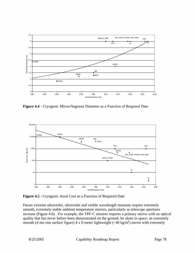
8/25/2005 Capability Roadmap Report Page 78
PI
FISI
LF
WS LIDAR, MTRAP, BHI, BBO
SAFIR
TPF-I
DEM, IP, BHF
JWST
SIM
ASMD
Spitzer
Hubble
0
0.5
1
1.5
2
2.5
3
3.5
4
4.5
1980 1985 1990 1995 2000 2005 2010 2015 2020 2025 2030
Need/Readiness Date
Mirr
or/S
eg D
iam
eter
(m)
Figure 4.4 - Cryogenic Mirror/Segment Diameter as a Function of Required Date
Hubble Spitzer
ASMD SIMJWST
DEM, IP, BHF
TPF-I
SAFIR
WS LIDAR, MTRAP, BHI, BBO
LF
FISI
PI
1
10
100
1,000
10,000
100,000
1980 1985 1990 1995 2000 2005 2010 2015 2020 2025 2030
Need/Readiness Date
Are
al C
ost
($K
/m2)
Figure 4.5 - Cryogenic Areal Cost as a Function of Required Date Future extreme ultraviolet, ultraviolet and visible wavelength missions require extremely smooth, extremely-stable ambient temperature mirrors, particularly as telescope apertures increase (Figure 4.6). For example, the TPF-C mission requires a primary mirror with an optical quality that has never before been demonstrated on the ground, let alone in space: an extremely smooth (4 nm rms surface figure) 4 x 8 meter lightweight (~40 kg/m2) mirror with extremely

8/25/2005 Capability Roadmap Report Page 79
uniform coating reflectivity and polarization properties. Because of launch vehicle limitations, some future missions may choose a segmented, deployable mirror. While it is easier to manufacture smaller mirror segments, a segmented mirror telescope has its own challenges. To minimize scattered light and diffraction effects, the segments must be polished all to the mirror’s physical edge while their positions must be controlled to extreme tolerances (0.1 nm). Three specific enabling coating technologies are 80% reflectivity coatings from 90 to 120 nm, 0.1% uniform reflectivity and 0.1% uniform polarization coatings from 400 to 1000 nm, and improved dichroic, spectral and combiner coatings. Future x-ray and far-ultra-violet missions require large-aperture precision-quality grazing incidence mirrors. The technology required to produce these mirrors is revolutionary when compared to Chandra optics. Technology is needed to manufacture 1 to 2 meter-class mirrors with two orders of magnitude (100X) reduction in both areal density and areal cost. This will require developing new materials and new fabrication processes, and the mechanical support, alignment and stability of such optics are an additional significant challenge.
LISA, 10m Flight
CON-X, 20m Flight
TPF-C, 10m Flight1.0E-03
1.0E-02
1.0E-01
1.0E+00
1.0E+01
1.0E+02
1.0E+03
1.0E+04
2000 2005 2010 2015 2020 2025 2030
Need/Readiness Date
Con
trol
Acc
urac
y (n
m)
UVIO 40mSpace Assembled
FISI, 40mSpace Assembled
LF, 40mSpace Assembled
SAFIR, 40mFlight
Figure 4.6 - Structural Stability and Precision as a Function of Required Date 4.1.5.2 Wavefront Sensing and Control & Interferometry Many future missions will require large aperture telescopes to collect faint light from distant and cold sources and to provide high angular resolution to investigate the “fine structure” of the universe. Because of the size of these apertures and the need to make them light enough for launch, their stiffness will be inadequate to maintain the excellent wavefront needed to achieve the high optical quality required for scientific investigations. Active wavefront sensing and control (WFSC) will be needed to compensate for wavefront errors in real-time and on-orbit, and

8/25/2005 Capability Roadmap Report Page 80
will enable more cost effective telescopes at higher performance levels than monolithic telescopes such as HST.
Alternatively, a spatial interferometer effectively divides a very large aperture telescope into separate smaller, discrete apertures. Extremely high angular resolution is enabled by combining these smaller aperture telescopes across areas larger than can be covered by a single aperture, in some cases so large that the separate telescopes can no longer be structurally connected, but instead must be flown separately and use WFSC to create a large synthetic aperture.
Both single-aperture telescopes and interferometers require new wavefront sensing and control technology. WFSC is a system-level technology that includes sensing a reference source, signal processing, dynamic computation of parameters to control opto-mechanical devices, and distributed system communication to a mechanical control system. Telescope reference sources include lasers, edge sensors on the optic, or a sufficiently source in the field of view.
Ground-based testbeds are essential for developing the ability to sense and control wavefronts under realistic conditions. Several WFSC testbeds were developed for both JWST and SIM, and have been in active use for several years. New missions will require increasingly complex test beds. Technology is needed to better calculate and emulate the space environment (0-g, radiation field, thermal background, and space contamination). Fundamental research is needed in algorithm development, high speed digital signal processing, actuator devices, low power devices, long life-time lasers, and advanced sensors. The first key mission for this technology after JWST is TPF-C, which will need to sense and correct the wavefront to two orders of magnitude greater accuracy than JWST. TPF-C will also need speckle-suppression hardware and software to achieve the required 1010 contrast in broadband light. LUVO, with its shorter wavelengths, requires five times better WFSC (8 nm rms) than does JWST. The LUVO WFSC needs to operate continuously in an autonomous, closed- loop fashion. Formation-flying systems, such as TPF-I, stellar imager, and Life Finder will not be possible without advanced WFSC. In addition, low cost 3-meter class telescopes with multiple applications ranging from imaging to coherent collection (lasercomm and LIDAR) will require high temporal bandwidth active control. Such low-cost modest-sized apertures will enable more affordable solar, Earth science, and astronomy missions than now possible. Laser metrology is under development for SIM. Future missions will require lasers to operate over greater distances with longer in-space lifetimes and much more complicated mechanical, power and thermal system architectures. The control of wave fronts for TPF-C will require 50pm (λ/10,000) deformable mirrors stable over periods of hours. Cryogenic precision motion control is required for infrared systems. Closed- loop intelligent control of the entire system, involving multiple sensors and multiple structures, operating at a variety of temporal bandwidths, will be required. A variety of hardware approaches, including actuated hybrid mirrors, nanolaminate mirrors, deformable mirrors (including MEMS) and actuators require further development.
8/25/2005 Capability Roadmap Report Page 81
Ground-based testbeds are needed to explore system trades, develop and validate algorithms, and validate models, and they must be used in.continuous iteration between concept development and algorithms/modeling. Pathfinders, including flight demonstrators, will be critical to future mission success. 4.1.5.3 Distributed and Advanced Spacecraft Systems A Distributed and Advanced Spacecraft System (DASS) is a set of more than one spacecraft whose dynamics are coupled through a cooperative sensing and control architecture. This enables a distributed network of individual vehicles to act collaboratively as a single functional unit that can exhibit a common system wide capability. A key challenge of DASS is the need to build that multiple spacecraft, requiring a reduction of development and test costs for replicated spacecraft to enable competitive formation flown systems. Current formation flown systems rely upon propulsion to maneuver and maintain formation, thereby limiting mission lifetime and contaminating their environment (deposition on optical surfaces, plume impingement, thermal emission). Propellant- less formation flight should be investigated including the use of natural orbits, tethers, natural fields (magnetic, solar pressure), as well as potential fields generated by the spacecraft themselves (electro-magnetic, electro-static). Roughly three quarters of the long term future Earth and space science missions baseline distributed, formation-flying architectures. Yet, no mission has yet flown that begins to demonstrate the technology needed for these missions. Several on-orbit technology demonstrations have entered development, but were all cancelled prior to flight. Due to the numerous low-TRL capabilities that need to be matured, it may be too risky to demonstrate them all on one precursor mission or to mature them individually through a sequence of independent free-fliers (cost). DASS would benefit from a reconfigurable test platform where technology “layers” can mature under phased development, first maturing algorithms in a risk-tolerant setting and then maturing spacecraft sub-systems including propulsion, sensing, and communications, followed by payload technologies including collectors, combiners and optical control. Such a test sequence could be based upon the internal and external ISS test environments. 4.1.5.4 Cryogenic and Thermal Control Systems Cryogenic and thermal control systems include passive and active technologies used to cool large optical systems. The state-of-the-art in this area is the sunshade and thermal isolation being employed to passively cool JWST. Heat switches, advanced radiators, heat pipes, and capillary pump loops are all technologies, which need to be further improved both in efficiency, size, and cost to better enable high- and low-temperature cooling applications. The area of coolers greatly overlaps with the needs of scientific sensors, which also includes this capability. One key area that will greatly enable colder future telescopes is passive and actively cooled mirrors. As can be seen in Figure 4.7 below, mirror temperature reduction produces a lower
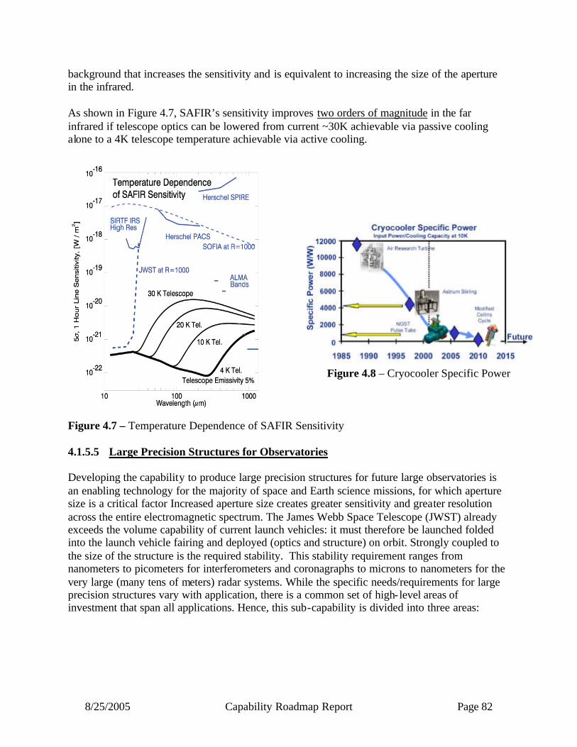
8/25/2005 Capability Roadmap Report Page 82
background that increases the sensitivity and is equivalent to increasing the size of the aperture in the infrared. As shown in Figure 4.7, SAFIR’s sensitivity improves two orders of magnitude in the far infrared if telescope optics can be lowered from current ~30K achievable via passive cooling alone to a 4K telescope temperature achievable via active cooling.
Figure 4.8 – Cryocooler Specific Power
Figure 4.7 – Temperature Dependence of SAFIR Sensitivity 4.1.5.5 Large Precision Structures for Observatories Developing the capability to produce large precision structures for future large observatories is an enabling technology for the majority of space and Earth science missions, for which aperture size is a critical factor Increased aperture size creates greater sensitivity and greater resolution across the entire electromagnetic spectrum. The James Webb Space Telescope (JWST) already exceeds the volume capability of current launch vehicles: it must therefore be launched folded into the launch vehicle fairing and deployed (optics and structure) on orbit. Strongly coupled to the size of the structure is the required stability. This stability requirement ranges from nanometers to picometers for interferometers and coronagraphs to microns to nanometers for the very large (many tens of meters) radar systems. While the specific needs/requirements for large precision structures vary with application, there is a common set of high- level areas of investment that span all applications. Hence, this sub-capability is divided into three areas:
8/25/2005 Capability Roadmap Report Page 83
• Structure Stability and Precision • Materials Properties • Implementation Technology
All three areas are strongly interconnected and must be approached with a long-term, system level investment strategy. For example, materials creep and precision thermal performance in a space environment are fundamental factors in any stability model, but appropriate environment material properties (particularly at very low temperatures) have never been measured for a wide range of potentially valuable materials. A broad understanding of materials properties will be needed to develop cost effective/acceptable risk stable structures. Similarly, issues with regard to implementation technology (e.g., launch load reduction systems and deployment vs assembly vs inflatabilty) factor strongly into design architectures. A comprehensive set of system-level trade studies comparing and quantifying the advantages is needed to guide investment strategies on a case-by-case basis. Large precision structures are a capability being developed for the first time with JWST. Future mission studies are developing mission requirements for size, low mass, and stability that greatly exceed those of JWST. If these future telescope/observatory missions are to be realized we must have the capability to develop larger precision structures. 4.2 Roadmap Development 4.2.1 Legacy Activities and Roadmap Assumptions This roadmap traces directly back to the Vision for Space Exploration to “Conduct advanced telescope searches for Earth- like planets and habitable environments around other stars”. It is fully consistent with the Aldridge Report which stated “The Commission finds implementing the space exploration vision will be enabled by scientific knowledge, and will enable compelling scientific opportunities to study Earth and its environs, the solar system, other planetary systems and the universe”. Finally, it draws much of its strategic guidance from NASA’s Direction for 2005 and Beyond (budget supplement) and the most recent National Academy of Sciences Astronomy and Astrophysics Decadal Survey. The ATO Roadmap assumed for planning purposes the list of missions and launch dates provided by APIO and verified through dialog with Strategic Roadmap panels. A summary of the assumed missions is provided on the roadmap timeline. JWST and SIM were included on the timelines for reference and are not part of the roadmap as they are in Phase B. Mission technology needs were based on NASA heritage roadmaps and presentation and reference material provided to the ATO committee from mission representatives. In addition, a number of more specific assumptions concerning the scope of this roadmap were closely coordinated with other roadmaps, particularly the Scientific Instrument and Sensor Capability Roadmap. Specifically, the Scientific Instrument and Sensor roadmap was assumed to contain heat pipe cooling to radiators, optical bench cooling, detector cooling, instrument optics, microwave system electronics and antennas/waveguides, and laser systems. The modeling roadmap committee was assumed to cover modeling and integrated modeling tools. In addition to this

8/25/2005 Capability Roadmap Report Page 84
coordination with other roadmaps, an assumption was made regarding the fact that the Explorer and Discovery programs were not called out in the roadmap and were only covered as part of the general need for low cost 3-meter class telescopes and associated technologies that could enable these types of missions 4.2.2 Capability Breakdown Structure The capabilities and technologies that comprise this roadmap are summarized on the Capability Breakdown Structure (CBS) shown in Figure 4.9. As can be seen, the roadmap consists of six basic areas, each of which is further broken down into sub-capabilities. The key area of optics shows up first and is organized principally by wavelength. Another critical area for many future missions is Wavefront Sensing and Control (including interferometry and testbeds). The third area, Distributed and Advanced Spacecraft Systems (DASS), becomes increasingly important in the longer term, as the requirement for aperture size exceeds the limits of a single mechanical structure. Large Precision Structures and Cryogenic and Thermal Control Systems will also providing enabling technologies for many future systems, and Infrastructures are addressed because of the extremely broad, critical impact they will have on future space telescope and observatory architectures.

8/25/2005 Capability Roadmap Report Page 85
Capability Breakdown Structure
Optics
4.1Lead: Phil Stahl
Crygenic NormalIncidence Optics
(IR,FIR,Submm,uwave)4.1.1
4.1.2
Precision NormalIncidence Optics
(EUV, UV, Vis, etc.)
Grazing IncidenceOptics (X-ray, etc.)
4.1.3
4.1.4
Diffractive, Refractiveor Other Optics
(Gamma Ray, X-Ray, etc.)
Lead: Jim Fienup
Wavefront Sensing
4.2.1
4.2.2
Metrology
Wavefront Control
4.2.3
Lead: Dave Miller
Platforms
4.3.1
4.3.2
Systems
Subsystems
4.3.3
Lead: Ron Polidan
Structure Stability& Precision
4.4.1
4.4.2
Materials Properties
4.4.3
4.4.4
Pointing and Control
Lead: Jim Oschmann
Passive Cooling
4.5.1
4.5.2
Active Cooling
Thermal Isolation
4.5.3
Lead: Jim Burge
Integration &Test Facilities
4.6.1
4.6.2
In-space ObservSupport/Servicing
Workforce
4.6.3
4.2 4.3 4.4 4.5 4.6
Wavefront Sensing& Control
& Interferometry
Distributed andAdvanced
Spacecraft SystemsLarge Precision
Structures
Cryogenic & Thermal Control
SystemsInfrastructure
Advanced Telescopes and Observations
Chair: Lee Feinberg Howard MacEwen
WFSCI Testbeds
4.2.4
ImplementationCapability
4.0
Figure 4.9 – Capability Breakdown Structure
8/25/2005 Capability Roadmap Report Page 86
4.2.3 Roadmap Logic The capability roadmap in this report is a summary level roadmap. This summary level roadmap includes only a roll up of the key sub-capabilities milestone readiness to support a particular mission requirement. Detailed sub-capability and technology roadmaps showing the technology progression and sub-capability development were presented to the NAS and are available in the document sharing system. In the top blue banner of the roadmap, there are those key missions that are pertinent to the roadmap among those derived from the April 15, 2005 interim document delivered by the strategic roadmaps and displayed in the CRM Planning Milestones Chart. The green banner below represents a summary rollup of key capabilities from each of the various capability breakdown structure elements. The peach colored swim-lanes represent the individual top level capability breakdown structure element and the sub-capabilities within this roadmap. The triangles represent the date that the capability is ready to support a given mission, and the diamonds represent decision points.

8/25/2005 Capability Roadmap Report Page 87
Capability Roadmap: Advanced Telescope Observatories (ATO)
4.1 Optics
4.2 Wavefront SensControl + Interfer
4.3 Dist. Adv. S/C Systems
4.4 Large Structures
4.5 Cryogenic & Thermal Control
4.6 Infrastructure
4.0 Advanced Telescope Observatories (ATO) (Key Events / Milestones)
2005 2010 20202015
Key Exploration Architectural Assumptions
2016TPFC
2017CON-X
2022IP
2015TROPWind LIDAR
2011JWST
2012SIM
2014LISA
2019TPFI 2022
SAFIR
3m “Low Cost” active telescopes
High Contrast ImagingGravity Wave
Detection
X-ray Spectroscopy
Active/Passive Cooled TelescopeLarge Baseline Cryo
Nulling/Optics, Prec. Form Fly.
Formation Flying
Observ.Servicing
Lg. Micrw. Polariz. Optics
Large Multi-Spacraft Constel.
SMD, Replicated mirrors 1.8m Prec. Optic 4x8m Prec. Optic
1m 15” X-ray Mirror 4m Cryo Mirror
Low Cost Cryo Mirror
Speckle Sensing/CtrlHigh Precision Metrology Precision Path Control
Active Control
Disturbance Redn Sys Prec. Form. FlyingForm. Flying 50-100nanosats
Prec. Structures – Stability and Isolation Prec. Struct. – Large and Cryo
Active/Passive Cooled Mirrors4-10K Active Cooling
10m, 4K Test FacilityLarge, High Perf. Test Facility
Low Cost Cryo Mirror
2016GEC
A
A
B
LARGE µWAVE
Figure 4.10a – Capability Roadmap

8/25/2005 Capability Roadmap Report Page 88
Capability Roadmap: Advanced Telescope Observatories (ATO)
4.1 Optics
4.2 Wavefront SensControl + Interfer
4.3 Dist. Adv. S/C Systems
4.4 Large Structures
4.5 Cryogenic & Thermal Control
4.6 Infrastructure
4.0 Advanced Telescope Observatories (ATO) (Key Events / Milestones)
2020 2025 2030
Key Exploration Architectural Assumptions
2026 LF
2034PLANET IMAGER2028 BHI, BBO
2032FIRSI
2030STELLAR IMAGER
2025 GEO Surface Deformation
2022Geo LIDAR
2021Mag Con
Highly Precise Sens. and
ControlLong Distance (FF)
Cryo Sens/Ctrl
Precision FF WFSC
In Space Assembly/ 1000m2 Observatory
20,000 m2 Observatory
30-meter Micr. Antenna
25 meter Class Telescopes50 meter Class Telescopes
.1 arcsec X-ray optics
Extreme Range Prec. Metrology.05nm WFS+DM
1um metrol. over 1Km
Precision Formation Flying
30 Meter Antennas
Large Assembled Structures
Large High Prec. Cryo Structures
4 K Higher Capacity Cooler
4 K High Efficiency Cooler
4 K Zero Vib Cooler
Observatory Servicing/Assembly
2024LUVO
B
AA
Figure 4.10b – Capability Roadmap

8/25/2005 Capability Roadmap Report Page 89
4.2.4 Infrastructure Assessment Two key areas of infrastructure have been considered as part of the roadmap activity: Test Facilities and Systematic Modeling using flight data. These two areas are summarized below: 4.2.4.1 New test facilities New facilities for thermal vacuum testing need to be considered to execute this roadmap. Large thermal vacuum test facilities have historically been a major cost and schedule consideration for large space telescopes, and will be even more challenging for future 10-meter and larger space telescopes. In the past, individual missions have been responsible for modified or new facilities even though they can often benefit multiple missions. Next generation NASA missions, such as TPF-C, Con-X, very large microwave apertures, and SAFIR, will build upon the test legacy of JWST, but will have new and unique test facility requirements. NASA must decide whether use of existing facilities is sufficient or whether a new facility that can more cost-effectively accommodate these and other missions is necessary. If a new facility is developed, it will be required to maximize flexibility in the cryo-thermal system, the cryogenic distribution system, optical metrology penetration, access ports for payload installation, and vibration isolation systems to accommodate future programs. The facility development team will need expertise in cryogenics, vibration isolation methods, contamination, and optical testing to ensure success of the testing, but also to minimize the overall cost to the programs. Finally, the facility plan must consider programmatic and logistic factors, such as the transportation of payloads to and from the facility and program schedule impacts. As plans for the future test facility needs mature, NASA should work with other government agencies, for example, through the Large Optics Working Group of the Space Technology Alliance to assure other agency interests are considered in the development and fabrication of the facility. 4.2.4.2 Systematic model validation using flight data Developing the infrastructure for very large, future systems will require as yet unplanned test and analysis of data from existing flight programs. Larger optical systems that rely on in-space assembly will use analysis and test techniques developed and verified on current programs such as JWST. It is essential to verify that subsystem analysis tools provide adequate insight into the end- item performance parameters. Additional telemetry may also be required to verify analytical models to ensure that future on-orbit assembly and maintenance systems will operate as predicted. By starting to build the analytical tools soon and combining these tools with a robust verification plan during traditional integration and testing of current flight programs will provide a high level of confidence when we begin to develop on-orbit assembly and test programs for new missions. If these tools are not developed early, critical failures could occur that would impact the ability to execute this new class of program in a cost effective manner.

8/25/2005 Capability Roadmap Report Page 90
4.2.4.3 On-Orbit Servicing and Assembly Future space telescopes will be complex, expensive, and operating at the Sun-Earth L2 location. The ATO roadmap committee considered whether it could be cost-effective to first develop the capability to service and followed by the capability to assemble future large optical systems. In particular, we considered whether robotics technology as was considered for servicing the Hubble Space Telescope could be employed to avoid the necessity of developing human space capability. The conclusion of this committee is that cost-effective on-orbit servicing and assembly utilizing robotic technology is possible if it leverages other NASA goals for in-space operations, such as a requirement to assemble the human transfer vehicle to Mars or in-space support for lunar surface operations. Therefore, leveraging opportunities should be pursued. A decision to service or assemble a telescope needs to be made early in the observatory architecture development. For this reason, SAFIR seems to be the logical first observatory that could benefit from servicing because of its timing, complexity, and potential for additional upgrades. Future larger aperture telescopes, such as Life Finder, are optimal candidates for on-orbit assembly because their size and mass may exceed plausible future launch vehicle size.

8/25/2005 Capability Roadmap Report Page 91
4.3 Summary The Advanced Telescope and Observatory roadmap closely coordinated with other capability roadmaps during the process of developing this roadmap. There are several capability roadmaps that have connections to this roadmap, but the tightest coupling is with the Scientific Instrument and Sensor Capability Roadmap. For this reason, this roadmap should be viewed in coordination with that roadmap and the recommendations from this roadmap should be considered with that in mind. While our roadmap represents a snapshot in time as to NASA’s advanced telescope and observatory capability needs, it should be understood that these capabilities and needs change over time and therefore this roadmap needs to be considered in that light.

8/25/2005 Capability Roadmap Report Page 92
Acronym List •AMSD = Advanced Mirror System Demonstrator •ConX = Constellation X •DEM = Dark Energy Mission •EASI = Earth Atmospheric Space Interferometer •EUXO = Early Universe X-ray Observer (formerly Gen X) •FIRSI = Far Infrared and Sub-millimeter Interferometer (formerly SPECS) •GEC = Geospace Electrodynamics Connections •GSM = Global Soil Moisture •IP = Inflation Probe (formerly CMB Pol) •ISC = In-space Construction/Servicing •Leo LFSM = Leo Low Frequency Soil Moisture •LF = Life Finder •LFFInSAR = L-band Formation Flying InSAR •LISA = Laser Interferometer Space Antenna •MEMS = Micro-Electro-Mechanical System •MMS = Magnetospheric Multiscale •MTRAP = Magnetospheric Transition Region Probe •PI = Planet Imager •SI = Stellar Imager •SMD = Segmented Mirror Demonstrator •UVOI = UV Optical Interferometer (formerly Stellar Imager) •WS LIDAR = Wide Swath LIDAR

8/25/2005 Capability Roadmap Report Page 93
NASA
Capability Road Map (CRM) 5
Communication and Navigation (CN)
Executive Summary
Chair: Robert Spearing, NASA HQ Co-Chair: Michael Regan, DoD COMMFIO
Coordinators
Directorate
Michele Gates, NASA SOMD
APIO
Steve Mecherle, Innocept
Team Members
NASA / NSF
Michael Hawes, NASA HQ Michael Luther, NASA HQ
Patrick Smith, National Science Foundation
Academia
John Baras, University of Maryland
Industry
Greg Akers, CISCO Thomas Brackey, Boeing

8/25/2005 Capability Roadmap Report Page 94
5 Communication and Navigation Capability (Roadmap 5) 5.1 General Capability Overview 5.1.1 Capability Description The space communication and navigation capability will fully enable evolution of the exploration and science programs. By providing connectivity to surface exploration and science vehicles and spacecraft, this capability ensures safe and productive mission operations. This capability is critical to eight other capabilities and moderate in relationship to the reminder. The communications and navigation (C&N) capability is unique in that an architecture that defines it exists today to support current missions. The capability roadmap originates at this current state and evolves into the future. This evolution, required to meet the expanding needs of the exploration and science programs, involves the development of both architectures and enabling technology. The capability described in this report is based upon the current state of strategic roadmap development. The C&N capability of the future, as pictured in Figure 5.1, is a highly adaptable network of networks that will rely on the modularity of relay satellite constellations, the flexibility of technology such as programmable communications systems, and an interoperable framework of spectrum, protocols and network architecture that will enable plug-and-play additions.
Figure 5.1 – Vision for the Communications and Navigation Architecture ~2030
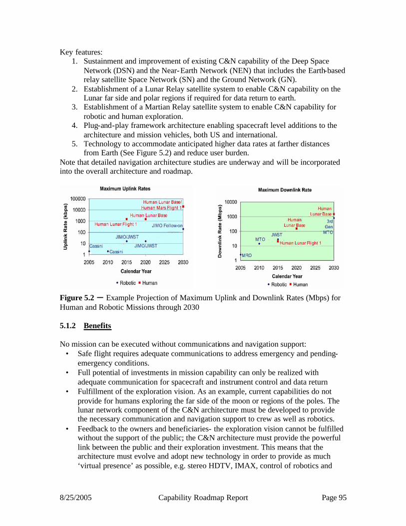
8/25/2005 Capability Roadmap Report Page 95
Key features: 1. Sustainment and improvement of existing C&N capability of the Deep Space
Network (DSN) and the Near-Earth Network (NEN) that includes the Earth-based relay satellite Space Network (SN) and the Ground Network (GN).
2. Establishment of a Lunar Relay satellite system to enable C&N capability on the Lunar far side and polar regions if required for data return to earth.
3. Establishment of a Martian Relay satellite system to enable C&N capability for robotic and human exploration.
4. Plug-and-play framework architecture enabling spacecraft level additions to the architecture and mission vehicles, both US and international.
5. Technology to accommodate anticipated higher data rates at farther distances from Earth (See Figure 5.2) and reduce user burden.
Note that detailed navigation architecture studies are underway and will be incorporated into the overall architecture and roadmap.
Figure 5.2 – Example Projection of Maximum Uplink and Downlink Rates (Mbps) for Human and Robotic Missions through 2030 5.1.2 Benefits No mission can be executed without communications and navigation support:
• Safe flight requires adequate communications to address emergency and pending-emergency conditions.
• Full potential of investments in mission capability can only be realized with adequate communication for spacecraft and instrument control and data return
• Fulfillment of the exploration vision. As an example, current capabilities do not provide for humans exploring the far side of the moon or regions of the poles. The lunar network component of the C&N architecture must be developed to provide the necessary communication and navigation support to crew as well as robotics.
• Feedback to the owners and beneficiaries- the exploration vision cannot be fulfilled without the support of the public; the C&N architecture must provide the powerful link between the public and their exploration investment. This means that the architecture must evolve and adopt new technology in order to provide as much ‘virtual presence’ as possible, e.g. stereo HDTV, IMAX, control of robotics and

8/25/2005 Capability Roadmap Report Page 96
instruments from publicly accessible locations such as universities, real-time comm with crew, ultra-high resolution photography of planetary surfaces and so on. (Figure 5.2)
The benefits of the C&N architecture include enabling increased crew and robotic productivity through collaborative operation with ground controllers, maintaining safe operations, providing precision navigation, and providing coverage during critical operations. Coverage of critical operations was identified as a key recommendation by the Mars Program Independent Assessment Team (MPIAT). Table 5.1 - Key Architecture / Strategic Decisions
Key Architecture/Strategic Decisions
Date Decision is
Needed
Impact of Decision on Capability
1. Is coverage with communications connection needed for all critical maneuvers as required by Mars Program Independent Assessment Team Report (3/2000)?
2005
Determines critical decisions on TDRSS and Ka-Band antenna array needed to support Earth orbit of CEV and lunar backside burn.
2. Is continuous available communications connection necessary for crewed vehicles similar to the global communication required by the ISS PRD?
2005
Determines critical decisions on TDRSS near earth network and lunar array needed to support Earth orbit of CEV and lunar backside burn.
3. What will be the extent of development of Space Based Range as required by US Space Transportation Policy (12/2004)?
2005 Determines required decisions on TDRSS and near earth network needed to support Space Based Range capability.
4. What is the location of human Lunar landing: far side limb area or potential interest area as referenced by The Vision for Space Exploration (2/2004)?
2012 Defines communications and navigation capability that may require a lunar relay system.
5. Is connectivity required during surface operations supporting over-the-horizon communications between individual units or crew members.
2007 for lunar;
2012 for Mars
Lack of robust local network at lunar exploration site would constrain exploration operations. Lack of robust local network at Mars exploration site would constrain exploration operations.

8/25/2005 Capability Roadmap Report Page 97
Key Architecture / Strategic Decisions (Continued)
Key Architecture/Strategic Decisions
Date Decision is
Needed
Impact of Decision on Capability
6. Is sufficient bandwidth available to meet increasing requirements contained within roadmaps; for example, lunar and Mars strategic roadmaps? Reference the President’s Commission on Implementation of United States Space Exploration Policy (6/2004)
2010 Low data rates would constrain exploration activities at the moon and Mars.
7. What are the precision landing and navigation requirements for Lunar and Mars missions?
2007 for lunar;
2012 for Mars
Appropriate navigation capability will not be in place to enable precision asset placement.
5.1.3 Major Technical Challenges The unifying challenge in the communications area is the need to move more data with higher quality, efficiency, flexibility, and interoperability than is currently possible. Equally challenging is the need to conduct precision orbit and landing operations. As shown in Figure 5.2, both science and public interest are increasing the demand for greater data rates, and as we explore at increasing distances new approaches and improvements in technologies are necessary.

8/25/2005 Capability Roadmap Report Page 98
Table 5.2 – Major Technical Challenges 2006-2010 Development of “Plug and Play” interoperable networks providing flexibility to allow international participation at the spacecraft level.
• Issues: Spectrum, Protocols, Network Management & Services • Network of networks must be made adaptable through the use of programmable
devices- • Ad-hoc network communication capabilities with end-to-end encryption and policy
based architecture. Development of Uplink Arraying Technology to enable ground antenna array to also transmit reducing costs for the replacement and maintenance of ground systems
• Issues: alignment and tracking, measurement time-varying quantities, phasing, array elements distances
• 2006 –Validate arraying concept using three 34-m DSN antennas using a moon bounce, LEOS experiment, and satellite experiments
• 2010 – Initial evaluation of 12-m antenna array 2010 – 2020 Development of Optical Communication Capability (2018) for higher capacity communications at Mars and beyond with goal of 1 Gbps data rate at maximum Mars distance and on-station lifetime of 6 yrs).
• Challenges for Ground-based detector (weather & turbulence) and space-based detector (array size, mass)
Develop Spacecraft RF Technology Capability with high availability, reliability and increased bandwidth.
• Issues: space qualification of ground-proven 100kW Ka-Band TWTAs, and increase in operational reliability. Higher and more efficient Power Amplifiers: Traveling Wave Tube Amplifiers (TWTA) and Solid State Power Amplifiers (SSPA).
• Deployment mechanisms and increasing operating frequency to Ka-band (Mesh and Inflatable Antennas)
Complete implemention of transmit operational capability to ground antenna array. • 2013 – Expanded 12-m array with operational status; off-ramp: build additional 34-m
antennas • 2015 – If transmit array capability successful (see 2006-2010 above), then
decommission the 34m antennas and cancel building 6 additional 34m antennas. Develop Programmable Communication System Capability to provide flexible and adaptable communications systems with reduced mass, power, and weight.
• Goal data rates in 2020- 25 Mbps for landers & 500 Mbps for orbiters/CEV, w/ required power of 1-25 W
• Issues: reconfigurable logic, A/D converters, Memory, Hardware/Software (HW/SW) framework, common interfaces
Develop navigation capability for accurate positioning of spacecraft and landing support. • Issues : autonomous position determination and navigation support for Lunar far side
and polar operations

8/25/2005 Capability Roadmap Report Page 99
2020 and Beyond Develop higher capacity communications (Optical Communication) for more comprehensive Mars exploration
• Data rate at maximum Mars distance is 2 Gbps with an on-station lifetime of 8 yrs Develop Programmable Communication System to increase flexibility and adaptability with reduced mass, power, and weight..
• Data rates in 2030- 25-100 Mbps for landers & 1 Gbps for orbiters/CEV, w/ required power of 0.5 – 35 W
• Issues: reconfigurable logic, A/D converters, Memory, HW/SW framework, common interfaces
5.1.4 Key Capabilities The following key capabilities were selected to reduce the cost of the communications systems while enabling a reasonable communications service level to meet currently understood mission objectives. The service level is based on assumed data rates, link availability and quality of service discussed elsewhere in this document. For example, the uplink arraying concept would significantly reduce the replacement, maintenance and operations costs for the DSN. Table 5.3 - Key Capabilities
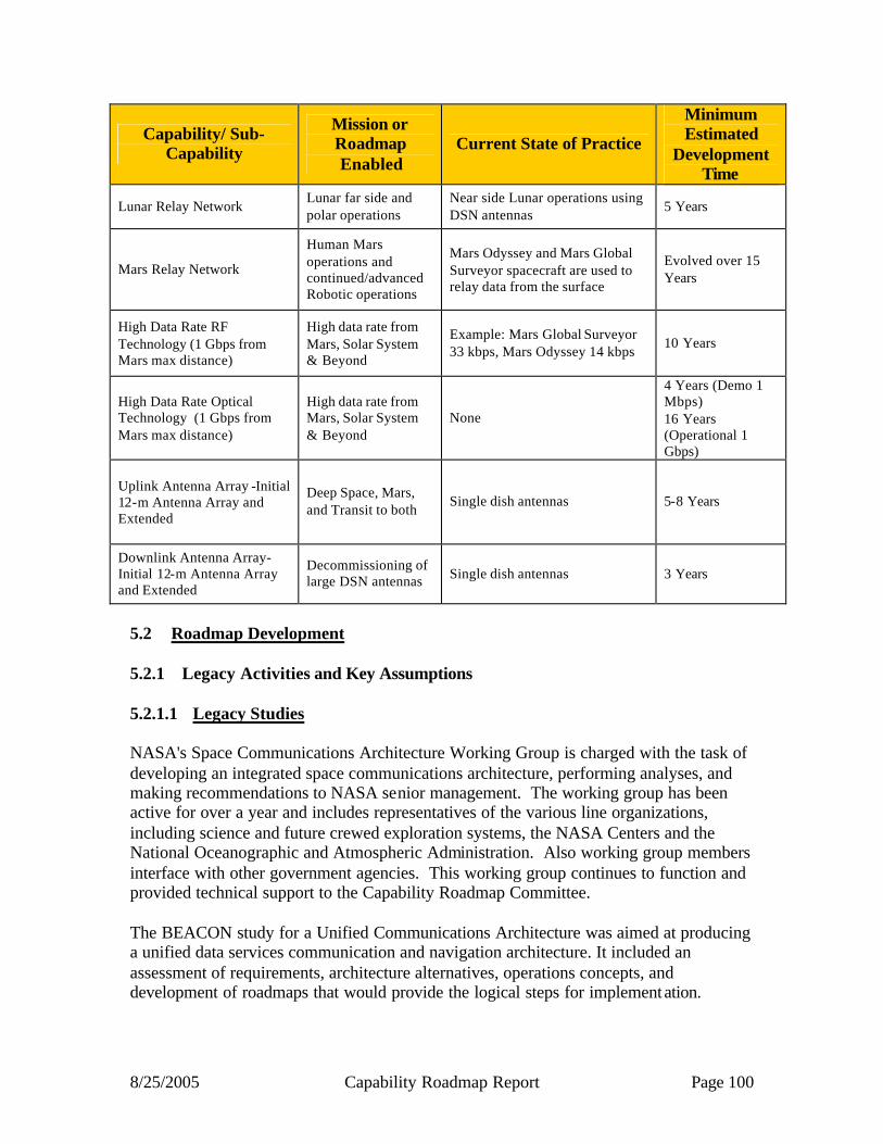
8/25/2005 Capability Roadmap Report Page 100
Capability/ Sub-Capability
Mission or Roadmap Enabled
Current State of Practice
Minimum Estimated
Development Time
Lunar Relay Network Lunar far side and polar operations
Near side Lunar operations using DSN antennas
5 Years
Mars Relay Network
Human Mars operations and continued/advanced Robotic operations
Mars Odyssey and Mars Global Surveyor spacecraft are used to relay data from the surface
Evolved over 15 Years
High Data Rate RF Technology (1 Gbps from Mars max distance)
High data rate from Mars, Solar System & Beyond
Example: Mars Global Surveyor 33 kbps, Mars Odyssey 14 kbps
10 Years
High Data Rate Optical Technology (1 Gbps from Mars max distance)
High data rate from Mars, Solar System & Beyond
None
4 Years (Demo 1 Mbps) 16 Years (Operational 1 Gbps)
Uplink Antenna Array -Initial 12-m Antenna Array and Extended
Deep Space, Mars, and Transit to both
Single dish antennas 5-8 Years
Downlink Antenna Array-Initial 12-m Antenna Array and Extended
Decommissioning of large DSN antennas Single dish antennas 3 Years
5.2 Roadmap Development 5.2.1 Legacy Activities and Key Assumptions 5.2.1.1 Legacy Studies NASA's Space Communications Architecture Working Group is charged with the task of developing an integrated space communications architecture, performing analyses, and making recommendations to NASA senior management. The working group has been active for over a year and includes representatives of the various line organizations, including science and future crewed exploration systems, the NASA Centers and the National Oceanographic and Atmospheric Administration. Also working group members interface with other government agencies. This working group continues to function and provided technical support to the Capability Roadmap Committee. The BEACON study for a Unified Communications Architecture was aimed at producing a unified data services communication and navigation architecture. It included an assessment of requirements, architecture alternatives, operations concepts, and development of roadmaps that would provide the logical steps for implementation.
8/25/2005 Capability Roadmap Report Page 101
The Deep Space Mission System (DSMS) roadmap describes the future characteristics of deep space missions and how DSMS plans to meet the challenges that will arise. The roadmap provides guidance in the following areas: research and technology development across NASA mission offices that are involved with deep space exploration; major investment decisions that will be made over the next 25 years, and; mission designers as to new and enhanced capabilities of the DSN. 5.2.1.2 Roadmap Development Strategy The development of the C&N capability hinges on a set of initial assumed requirements. These requirements will change as the exploration program matures. As a result the roadmap must accommodate decisions being built into the exploration plan, and the overall architecture approach must emphasize flexibility and evolvability to meet evolving needs and requirements. Initial focus has been on architecture and technology meeting near term budgetary action. 5.2.1.3 Assumed Top Level Requirements The following assumptions were used in the development of this Roadmap:
• Space-based range - relay telemetry form launch vehicles, command destruct, and redundant telemetry paths
• Human space flight in LEO during Constellation Configuration - continuous communications with all vehicles and crew, coverage for multiple vehicles, comm services for configuration assembly, re-entry communications, comm for telemetry and crew voice on ocean surface
• Robotic missions to the far side of the Moon - comm during all critical events and systems out of view of Earth-based antennas
• Crewed lunar mission support - continuous comm for vehicles and crew, coverage over the back side of the Moon for critical events and human surface operations, voice and data services between elements over the poles, as well as to and from Earth
• Robotic missions to Mars - connectivity during critical events and to vehicles and probes on Mars surface
• Crewed Mars missions - continuous connectivity to support surface operations

8/25/2005 Capability Roadmap Report Page 102
Assumed Data Rates Data rates will be major drivers for the C&N architecture as it evolves to meet the exploration and science mission needs. Currently, data rates are assumed based on assumed activities at various destinations in conjunction with characteristic data rates for typical data types. Example data types include High Definition Television (HDTV), Hyperspectral imaging, and audio. An example data rates scenario is shown in Figure 5.3. (NRT = near-real-time)
4 Mbps1 Mbps4NRTQuick Look
160 kbps20 kbps8NRTEngineering
12 Mbps1.5 Mbps8NRTVideoRobotic Rovers
150 Mbps150 Mbps11 dayHyperspectral Imaging
100 Mbps100 Mbps11 daySurface RadarRobotic Rovers
300 Mbps150 Mbps21 dayHyperspectral Imaging
200 Mbps100 Mbps21 dayOrbiting RadarScience Orbiters
150 Mbps150 Mbps11 dayHyperspectral Imaging
40 Mbps20 Mbps2NRTHDTV (Medical and PIO)Human Transports
20 Mbps20 Mbps11 dayHDTVBase
High R
ate
NRT
NRT
NRT
NRT
NRT
NRT
NRT
NRT
Latency
Operational
980 MbpsTotal
80 kbps20 kbps4Engineering
Science Orbiters
40 kbps20 kbps2Engineering
3 Mbps1.5 Mbps2VideoHuman Transports
80 kbps20 kbps4Engineering
400 kbps100 kbps4Helmet camera
40 kbps10 kbps4Speech
Astronauts
100 kbps100 kbps1Engineering
20 kbps10 kbps2SpeechBase
Total RateChannel Rate# of ChannelsChannel ContentUser
Figure 5.3 – Assumed Data Rates Scenario

8/25/2005 Capability Roadmap Report Page 103
5.2.2 Capability Breakdown Structure Rationale The Capability Breakdown Structure (CBS) (Figure 5.4) is indicative of one of the central issues of the C&N architecture: the C&N capability is really a set of services that are provided to users in various locations. By nature, the way in which a service is provided, or the difficulty in achieving service performance, is tied to the phase of flight or location. For this reason, the first level of capability breakdown represents providing C&N service during launch, Earth orbit, transit (to Moon, Mars, or beyond), Lunar operations, Mars operations, and exploration in the Solar System & Beyond. The sub capabilities then reflect the specific services needed in each regime.

8/25/2005 Capability Roadmap Report Page 104
Figure 5.4 – Capability Breakdown Structure Capability Breakdown Structure
Global Coverage
5.1.1
5.1.2
Assured Comm
Tracking
5.1.3
Tracking
5.2.1
5.2.2
Telemetry
Commanding
5.2.3
5.2.4
Mission Data
Tracking
5.3.1
5.2.2
Telemetry
Commanding
5.3.3
5.3.4
Mission Data
Positioning
5.4.1
5.4.2
Telemetry
Commanding
5.4.3
5.4.4
Mission Data
Positioning
5.5.1
5.5.2
Telemetry
Commanding
5.5.3
5.5.4
Mission Data
Positioning
5.6.1
5.6.2
Telemetry
Commanding
5.6.3
5.6.4
Mission Data
5.1 5.2 5.3 5.4 5.5 5.6
Launch Earth Orbit Transit Lunar Mars Solar System & Beyond
Spacecraft AnomallySupport
5.3.5
Spacecraft AnomalySupport
5.4.5
5.4.6
Crew Support
Spacecraft AnomalySupport
5.5.5
5.5.6
Crew Support
5.0 Communications and Navigation
Architecture Capability to Support Science and
Exploration
Chair: Robert SpearingCo-Chair: Michael Regan
Telemetry
5.1.4
Command Destruct
5.1.5 5.2.5
Spacecraft AnomalySupport
5.6.5
Spacecraft AnomalySupport
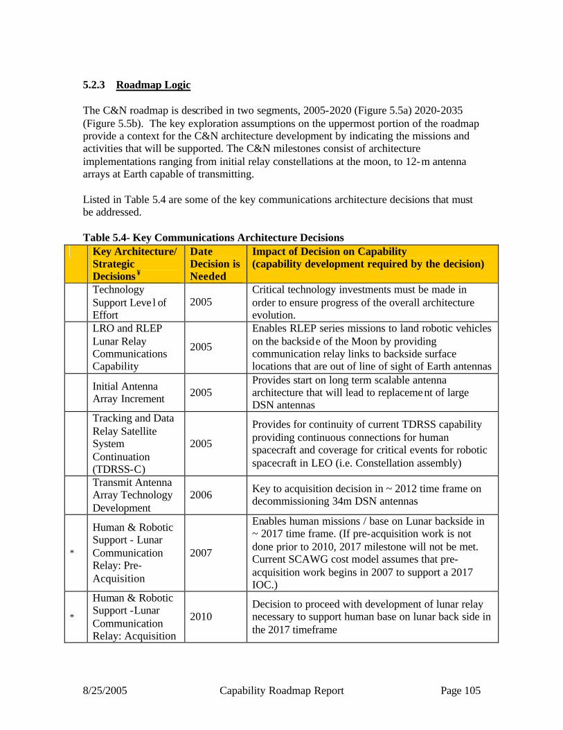
8/25/2005 Capability Roadmap Report Page 105
5.2.3 Roadmap Logic The C&N roadmap is described in two segments, 2005-2020 (Figure 5.5a) 2020-2035 (Figure 5.5b). The key exploration assumptions on the uppermost portion of the roadmap provide a context for the C&N architecture development by indicating the missions and activities that will be supported. The C&N milestones consist of architecture implementations ranging from initial relay constellations at the moon, to 12-m antenna arrays at Earth capable of transmitting. Listed in Table 5.4 are some of the key communications architecture decisions that must be addressed. Table 5.4- Key Communications Architecture Decisions
Key Architecture/ Strategic Decisions ¥
Date Decision is Needed
Impact of Decision on Capability (capability development required by the decision)
Technology Support Leve l of Effort
2005 Critical technology investments must be made in order to ensure progress of the overall architecture evolution.
LRO and RLEP Lunar Relay Communications Capability
2005
Enables RLEP series missions to land robotic vehicles on the backside of the Moon by providing communication relay links to backside surface locations that are out of line of sight of Earth antennas
Initial Antenna Array Increment 2005
Provides start on long term scalable antenna architecture that will lead to replacement of large DSN antennas
Tracking and Data Relay Satellite System Continuation (TDRSS-C)
2005
Provides for continuity of current TDRSS capability providing continuous connections for human spacecraft and coverage for critical events for robotic spacecraft in LEO (i.e. Constellation assembly)
Transmit Antenna Array Technology Development
2006 Key to acquisition decision in ~ 2012 time frame on decommissioning 34m DSN antennas
*
Human & Robotic Support - Lunar Communication Relay: Pre-Acquisition
2007
Enables human missions / base on Lunar backside in ~ 2017 time frame. (If pre-acquisition work is not done prior to 2010, 2017 milestone will not be met. Current SCAWG cost model assumes that pre-acquisition work begins in 2007 to support a 2017 IOC.)
*
Human & Robotic Support -Lunar Communication Relay: Acquisition
2010 Decision to proceed with development of lunar relay necessary to support human base on lunar back side in the 2017 timeframe
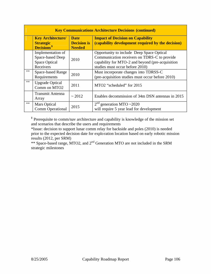
8/25/2005 Capability Roadmap Report Page 106
Key Communications Architecture Decisions (continued)
Key Architecture/ Strategic Decisions ¥
Date Decision is Needed
Impact of Decision on Capability (capability development required by the decision)
Implementation of Space-based Deep Space Optical Receivers
2010
Opportunity to include Deep Space Optical Communication receivers on TDRS-C to provide capability for MTO-2 and beyond (pre-acquisition studies must occur before 2010)
** Space-based Range Requirements 2010
Must incorporate changes into TDRSS-C (pre-acquisition studies must occur before 2010)
** Upgrade Optical Comm on MTO2 2011 MTO2 “scheduled” for 2015
Transmit Antenna Array ~ 2012 Enables decommission of 34m DSN antennas in 2015
** Mars Optical Comm Operational 2015
2nd generation MTO ~2020 will require 5 year lead for development
¥ Prerequisite to comm/nav architecture and capability is knowledge of the mission set and scenarios that describe the users and requirements *Issue: decision to support lunar comm relay for backside and poles (2010) is needed prior to the expected decision date for explo ration location based on early robotic mission results (2012, per SRM) ** Space-based range, MTO2, and 2nd Generation MTO are not included in the SRM strategic milestones
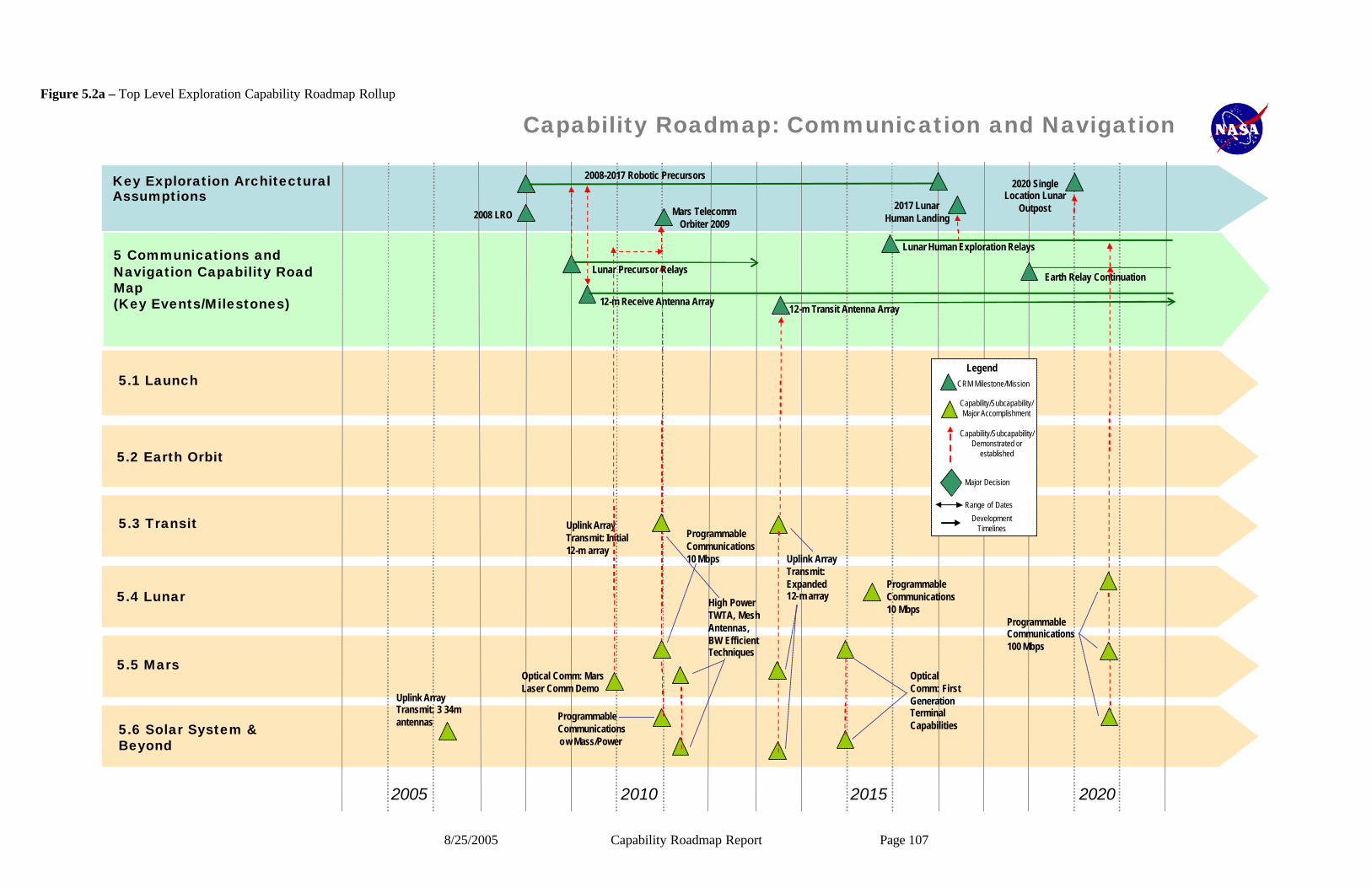
8/25/2005 Capability Roadmap Report Page 107
Capability Roadmap: Communication and Navigation
2005 2010 20202015
Key Exploration Architectural Assumptions
5.2 Earth Orbit
5.3 Transit
5.4 Lunar
5.5 Mars
5.6 Solar System & Beyond
5 Communications and Navigation Capability Road Map(Key Events/Milestones)
5.1 Launch
2008 LRO
2008-2017 Robotic Precursors
2017 Lunar Human Landing
2020 Single Location Lunar
Outpost
Uplink Array Transmit: 3 34m antennas
Lunar Human Exploration Relays
12-m Receive Antenna Array12-m Transit Antenna Array
Earth Relay Continuation
Uplink Array Transmit: Initial 12-m array
Programmable Communications 10 Mbps
Lunar Precursor Relays
Programmable Communications 100 Mbps
Mars Telecomm Orbiter 2009
Optical Comm: Mars Laser Comm Demo
High Power TWTA, Mesh Antennas, BW Efficient Techniques
Uplink Array Transmit: Expanded 12-m array
Programmable Communications 10 Mbps
Programmable Communications ow Mass/Power
Optical Comm: First Generation Terminal Capabilities
Capability/Subcapability/Major Accomplishment
Capability/Subcapability/Demonstrated or
established
CRM Milestone/Mission
Major Decision
Range of Dates
Development Timelines
Legend
Capability/Subcapability/Major Accomplishment
Capability/Subcapability/Demonstrated or
established
CRM Milestone/Mission
Major Decision
Range of Dates
Development Timelines
Legend
Figure 5.2a – Top Level Exploration Capability Roadmap Rollup
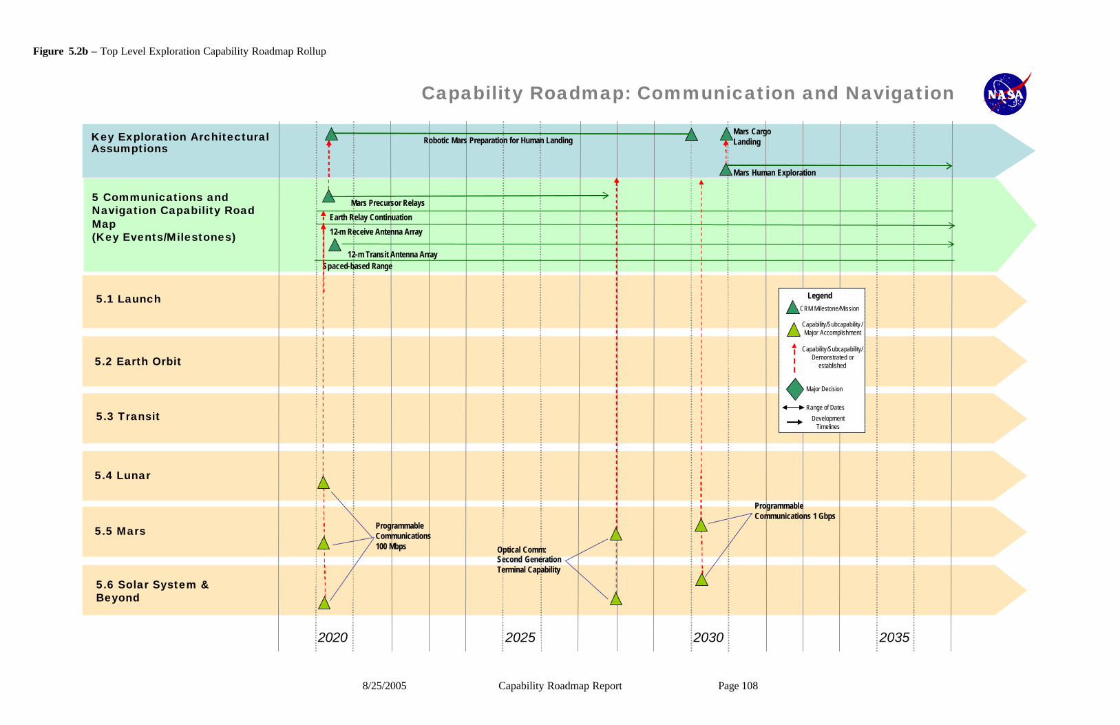
8/25/2005 Capability Roadmap Report Page 108
Figure 5.2b – Top Level Exploration Capability Roadmap Rollup
Capability Roadmap: Communication and Navigation
2020 2025 20352030
Key Exploration Architectural Assumptions
5.2 Earth Orbit
5.3 Transit
5.4 Lunar
5.5 Mars
5.6 Solar System & Beyond
5 Communications and Navigation Capability Road Map(Key Events/Milestones)
5.1 Launch
Robotic Mars Preparation for Human LandingMars Cargo Landing
Mars Precursor Relays
12-m Receive Antenna Array
Spaced-based Range12-m Transit Antenna Array
Earth Relay Continuation
Mars Human Exploration
Programmable Communications 1 Gbps
Optical Comm: Second Generation Terminal Capability
Programmable Communications 100 Mbps
Capability/Subcapability /Major Accomplishment
Capability/Subcapability/Demonstrated or
established
CRM Milestone/Mission
Major Decision
Range of Dates
Development Timelines
Legend
Capability/Subcapability /Major Accomplishment
Capability/Subcapability/Demonstrated or
established
CRM Milestone/Mission
Major Decision
Range of Dates
Development Timelines
Legend
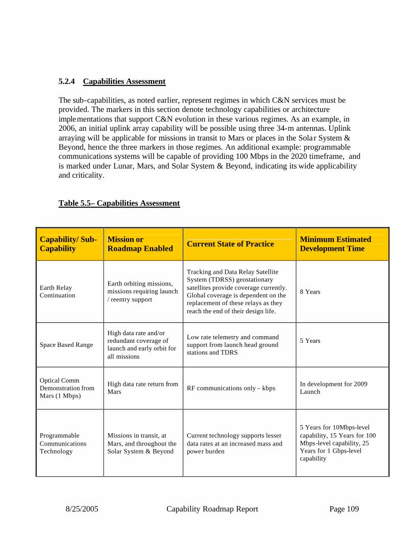
8/25/2005 Capability Roadmap Report Page 109
5.2.4 Capabilities Assessment The sub-capabilities, as noted earlier, represent regimes in which C&N services must be provided. The markers in this section denote technology capabilities or architecture implementations that support C&N evolution in these various regimes. As an example, in 2006, an initial uplink array capability will be possible using three 34-m antennas. Uplink arraying will be applicable for missions in transit to Mars or places in the Sola r System & Beyond, hence the three markers in those regimes. An additional example: programmable communications systems will be capable of providing 100 Mbps in the 2020 timeframe, and is marked under Lunar, Mars, and Solar System & Beyond, indicating its wide applicability and criticality. Table 5.5– Capabilities Assessment
Capability/ Sub-Capability
Mission or Roadmap Enabled Current State of Practice Minimum Estimated
Development Time
Earth Relay Continuation
Earth orbiting missions, missions requiring launch / reentry support
Tracking and Data Relay Satellite System (TDRSS) geostationary satellites provide coverage currently. Global coverage is dependent on the replacement of these relays as they reach the end of their design life.
8 Years
Space Based Range
High data rate and/or redundant coverage of launch and early orbit for all missions
Low rate telemetry and command support from launch head ground stations and TDRS
5 Years
Optical Comm Demonstration from Mars (1 Mbps)
High data rate return from Mars RF communications only – kbps
In development for 2009 Launch
Programmable Communications Technology
Missions in transit, at Mars, and throughout the Solar System & Beyond
Current technology supports lesser data rates at an increased mass and power burden
5 Years for 10Mbps-level capability, 15 Years for 100 Mbps-level capability, 25 Years for 1 Gbps-level capability

8/25/2005 Capability Roadmap Report Page 110
Capabilities Assessment – (Continued)
Capability/ Sub-Capability
Mission or Roadmap Enabled Current State of Practice Minimum Estimated
Development Time
Spectrum Interoperability
All co-located missions where data transfer can be routed through an alternate spacecraft
Planned interoperability for proximity communications at Mars: Example is MER data transfer through an ESA orbiter
Spectrum Agreements via the Space Frequency Coordination Group and the World Radio Council between 2005 and 2010
Communication Protocols Standardized
6 Years via CCSDS Development
Network Architecture and Management All Missions 2005-2010
5.2.5 Relationship to Other Capability Roadmaps The C&N capability roadmap has critical relationships with eight of the other capability areas. Details on the nature of those critical relationships follow. 5.2.5.1 In Space Transportation
• Requires Tracking Telemetry and Control (TT&C) link to Earth • Key dependence on TT&C during critical event coverage • Vehicle-to-Vehicle links needed for assembly and docking operations • Communications security needed • Navigation requirement is continuous • Navigation provided by combination of autonomous and linked methods • Requires time phasing of capability with missions
5.2.5.2 Advanced Telescopes and Observatories
• Critical dependence on TT&C and mission data transport links to Earth (or Earth orbiting relay)
• Potential TT&C and mission data transport links to lunar or planetary orbiter • Comm security needed • Dependence on navigation critical for formation flying, VLBI, or scientific instrument
pointing • Navigation provided by combination of autonomous and linked methods • May have crosslinks between array elements
8/25/2005 Capability Roadmap Report Page 111
5.2.5.3 Robotic Access to Planetary Surfaces
• Dependent on TT&C and mission data transport links to Earth, Earth orbiter, or lunar or planetary orbiter
• May require surface-to-surface links or network • Comm security needed • Navigation provided by combination of autonomous and linked methods • Requires time phasing of capability with missions
5.2.5.4 Human Planetary Landing Systems
• Critical dependence on assured TT&C, voice, and mission data transport links to Earth, Earth orbiter, or lunar or planetary orbiter
• May require surface to lander beacon link • May require surface-to-surface links or network • Comm security needed • Critical dependence on highly reliable, highly available navigation • Navigation provided by combination of autonomous and linked methods • Navigation and communication required for rendezvous and docking • May incorporate docking sensor on vehicle • Requires time phasing of capability with missions
5.2.5.5 Human Exploration Systems and Mobility
• Critical dependence on assured TT&C, voice, and mission data transport links to Earth, Earth orbiter, or lunar or planetary orbiter
• Astronaut EVA suits may require TT&C, voice and mission data links • May require surface-to-surface links or network • Comm security needed • Potential mission data dependence on in-space deployable antennas • Critical dependence on highly reliable, highly available navigation • Navigation provided by combination of autonomous and linked methods • Requires time phasing of capability with missions
5.2.5.6 Autonomous Systems and Robotics
• Critical dependence on system-to-system autonomous communication network for TT&C and mission data transport with systems located nearly anywhere
• May require links for critical event coverage • May require communication on demand networking • May require inter-vehicle communication for rendezvous / docking • Navigation provided by combination of autonomous and linked methods

8/25/2005 Capability Roadmap Report Page 112
5.2.5.7 Transformational Spaceport/Range
• Critical dependence on assured TT&C, voice, and mission data transport links to Earth or Earth orbiter
• Critical dependence on highly reliable, highly available navigation • Tradeoff of range radar or space-based range (SBR increases dependence on
comm/nav and GPS) • Range radar can provide autonomous tracking w/out dependence on vehicle TT&C • Comm security needed • Navigation provided by combination of autonomous and linked methods • Requires time phasing of capability with missions
5.2.5.8 Scientific Instruments and Sensors
• Critical dependence on TT&C and mission data transport links to Earth (or Earth orbiting relay)
• Potential TT&C and mission data transport links to lunar or planetary orbiter • Comm security needed • May have crosslinks between array elements • May require inter- instrument communications • Requires time phasing of capability with missions
5.2.6 Infrastructure Assessment Facilities and people are extremely important for the Communications and Navigation capability. While not exhaustive this listing indicates the breadth and depth of facilities and competencies that are needed for the Communications and Navigation capabilities. 5.2.6.1 Facilities and Assets:
• Deep Space Network ground stations at Canberra, Goldstone, Madrid • Ground stations including White Sands Complex, MILA, KSC, WFF, GRGT • Research and test facilities at JPL, GSFC, and GRC • Tracking and Data Relay Satellite System (TDRSS)
5.2.6.2 Critical workforce competencies:
• RF and Optical communications technologists • NASA: GSFC, JPL, GRC, JSC, KSC, and associated contractors • Laboratories: MIT Lincoln Labs, JHU Applied Physics Lab, Naval Research Lab,
Sandia National Lab, Air Force Research Lab • Universities

8/25/2005 Capability Roadmap Report Page 113
5.2.6.3 Human capital considerations :
• Critical competencies must be maintained • Improved workforce competency in new and emerging technology areas such as
optical communications and programmable communication systems
To be successful these assets must be carefully managed.
8/25/2005 Capability Roadmap Report Page 114
5.3 Summary The C&N Capabilities Roadmap process has identified the need for a robust, evolvable, scalable, and adaptable communications and navigation architecture. This capability is essential for the success of exploration and science missions and is either critical or moderate in relationship to the other 14 capabilities. The top- level vision for the C&N architecture consists of a network of networks based on the use of relay satellites at Earth, Moon, and Mars and replacement of the DSN antennas with scalable, small aperture antenna array technology. Key enabling technologies have been identified to ensure the success of this vision: optical communication, spacecraft RF technology, antenna array transmit technology and programmable communication systems. This initial roadmap was developed as a result of exploration and science inputs and assumptions to date, and architecture and technology analysis. Continuation of this work will include further assessment of enabling technology, network level management and protocols, and updating and validation of assumed driving requirements. In addition, the architecture will fully address the navigation aspects.

8/25/2005 Capability Roadmap Report Page 115
Acronym List
A/D – Analog/Digital AFSCN – Air Force Satellite Control Network ARC – Ames Research Center BW – Bandwidth C&N - Communications and Navigation CCSDS — Consultative Committee for Space Data Systems CEV – Crew Exploration Vehicle CM – Command Module COMM – Communications DSN – Deep Space Network ESA – European Space Agency FCC – Federal Communications Commission FF – Fast Forward FOM – Figure of Merit FOM — Figures of Merit FWD – Forward Link Gbps – Gigabits per second GDOP – Geodetic Dilution of Precision GEO – Geosynchronous Earth Orbit GN – Ground Network GPS – Global Positioning System GRC – Glenn Research Center GRGT – Guam Remote Ground Terminal GSFC – Goddard Space Flight Center GT – Ground Terminal HDTV – High Definition Television HPOA – High Power Optical Amplifier ISO – International Standards Organization ISS — International Space Station JIMO – Jupiter Icy Moons Orbiter JPL – Jet Propulsion Laboratory JTR – Joint Tactical Radio KSC – Kennedy Space Center KuSA – Ku-Band Single Access L&EO – Launch and Early Orbit L1 – LaGrange Point 1 L2 – LaGrange Point 2 LaRC – Langley Research Center LEO – Low Earth Orbit LLO – Low Lunar Orbit LMO – Low Moon Orbiter LOS – Line of Sight LRO – Lunar Reconnaissance Orbiter Mbps – Megabits per second

8/25/2005 Capability Roadmap Report Page 116
MCC – Mission Control Center MLCD – Mars Lasercom Demonstrator MOC – Mission Operations Center MTO – Mars Telecom Orbiter NAFCOM – NASA Air Force Cost Model Nav – Navigation NISN – NASA Information System Network NRT – Near Real Time NSF – National Science Foundation OC – Operations Center OPS – Operations PDD – Presidential Decision Directive PIO – Public Information Office R&D - Research and Development RE – Recurring Engineering RF – Radio Frequency RLEP – Robotic Lunar Exploration Program RS – Relay Satellite SA – Single Access SC – Spacecraft SDR – Software Defined Radio SFCG – Space Frequency Coordination Group SGL – Space Ground Link SLE – Space Link Extension SN – Space Network STS – Space Transportation System TDRSS — Tracking Data Relay Satellite System TT&C – Tracking, Telemetry and Command TWTA – Traveling Wave Tube Amplifier UHF – Ultra High Frequency UMD – University of Maryland at College Park USG – United States Government WRC – World Radio Conference WSC – White Sands Complex
8/25/2005 Capability Roadmap Report Page 117
NASA
Capability Road Map (CRM) 6
Robotic Access to Planetary Surfaces (RAPS)
Executive Summary
Chair: Mark Adler, NASA JPL Co-Chair: Bobby Braun, Georgia Institute of Technology
Coordinators
Directorate
Harley Thronson NASA SMD
Giulio Varsi, NASA SMD
APIO
Carl Ruoff, NASA JPL
Team Members
NASA / JPL
Samad Hayati, NASA JPL Ben Clark, NASA JSC Claude Graves, NASA JSC Dean Kontinos, NASA ARC Tom Rivellini, NASA JPL Brian Wilcox, NASA JPL Debora Fairbrother, NASA GSFC Henry Wright, NASA LaRC
Academia
Dave Miller, Massachusetts Institute of Technology
Industry
Steve Gorevan, Honeybee Robotics
Joe Parrish, Payload Systems Al Witkowski, Pioneer Aerospace
8/25/2005 Capability Roadmap Report Page 118
6 Robotic Access to Planetary Surfaces (Roadmap 6) 6.1 General Capability Overview 6.1.1 Capability Description This Robotic Access to Planetary Surfaces (RAPS) roadmap addresses the capabilities for missions that need to land, fly, rove, and dig on the surfaces or in the atmospheres of large bodies in our solar system, such as the Moon, Mars, Venus, Titan, Europa, Jupiter and Neptune, as well as capabilities to support sample returns to Earth. Due to the significant overlap in required functionality, this roadmap also includes aerocapture. (Many of the required atmospheric transit capabilities overlap directly with analogous capabilities required for the Human Planetary Landing Systems capability roadmap, though at different scales.) The systems outlined here have the job of delivering instruments to an atmosphere or surface, and/or delivering samples to the instruments. The instruments themselves are covered by another capability roadmap group. This capability roadmap does not cover operations at small bodies, i.e. asteroids or comets. It also does not cover robotic assistants for human missions, or robotic resource collection, e.g. mining, for ISRU. 6.1.2 Benefits The key capabilities outlined here enable missions that have high science value and that are called out as possible new starts in the next twenty years. In particular, missions that land greater mass provide greater mobility, access and transport surface material from depth, and implement required planetary protection on Mars for the purpose of life detection or sample return are enabled. Missions that enter the Venusian atmosphere and deliver long- lived landers to the surface are enabled. Missions that enter the Titan atmosphere and deliver airships with surface material access are enabled. Missions that enter the atmospheres of gas giants at high velocity are enabled. In addition, new mission concepts for the delivery of long-duration aircraft to Venus, Mars, or Titan, and for the delivery of a large number of small landers for landed network applications are enabled. 6.1.3 Key Architecture / Strategic Decisions Table 6.1 summarizes the key capability developments and the science strategy and mission launch date decisions that would drive those developments. [See the note in the Roadmap Development section on assumptions used for the numbers of years.] In the table below, “heavy Mars EDL” includes a set of capabilities, in particular higher performance thermal protection materials; guided lifting hypersonic flight; new, larger supersonic parachutes; and low velocity

8/25/2005 Capability Roadmap Report Page 119
touchdown systems. Similarly, “planetary protection” includes spacecraft sterilization, assured containment for Earth return, and sample operations in isolation in the Earth receiving facility. Table 6.1 - Key Decisions Key Architecture/Strategic Decisions
Date Decision is
Needed
Impact of Decision on Capability
Decision to launch Mars Sample Return.
9 years before the intended launch.
Latest date to start planetary protection, Earth entry, heavy Mars EDL, advanced mobility, and sample handling capabilities.
Decision to launch an in situ life-detection laboratory to Mars, either rover-borne or on a fixed platform deep drill.
7 years before the intended launch (though see next row).
Latest date to start contamination reduction and sterilization, and complex sample handling.
Decision to launch a deep drill life-detection laboratory to Mars.
8 years before the intended launch.
Latest date to start an autonomous deep drill, and down-hole instrumentation.
Decision to continue the exploration of Titan with a long- lived airship capable of surface sampling.
8 years before the intended launch.
Latest date to start airship materials, guidance and control, propulsion, and surface interaction.
Decision to explore the Venusian surface with a long- lived laboratory.
7 years before the intended launch.
Latest date to start extreme environment survival system studies and component development.
Decision to deliver deep atmospheric probes to Jupiter, or decision to conduct an aerocapture at Neptune.
12 years before the intended launch.
Latest date to start thermal protection materials, refurbish test facilities, and analysis capabilities.
6.2 Roadmap Development 6.2.1 Top Level Architectural Assumptions & Applications The design reference missions used to drive key capabilities were derived from existing Mars and Solar System strategic plans, and updated as the Mars and Solar System SRM teams progressed in their work. The value of this roadmap is not in any absolute dates that might be laid out, but rather in what capabilities are needed for a given mission type, and the amount of time required to develop those capabilities before a new start could adopt that capability at an acceptable level of remaining development risk. Out of the set of all envisioned missions that fall in the scope of this roadmap, a subset was selected that drive the capabilities investigated. Those missions are:
• Mars Sample Return
8/25/2005 Capability Roadmap Report Page 120
• Titan Explorer (airship) • Europa Astrobiological Lander • Mars Deep Drill • Mars Astrobiological Field Laboratory • Venus Surface Explorer • Jupiter Atmospheric Probes • Neptune Orbiter (aerocapture)
The number of years listed in Table 6.1 assume that the capability development must be complete four years before launch. It is possible to accelerate the schedule by overlapping the capability development with the project development by one to three years, given appropriate management of the development risk. 6.2.2 Legacy Activities and Roadmap Assumptions There were three previous activities that this roadmap drew on. Two of them provided useful material for advances in nuclear and non-nuclear power systems:
• Advanced Radioisotope Power Systems Report, Rao Surampudi et al., JPL D-20757 6/01, March 2001
• Solar Cell and Array Technology for Future Space Science Missions, Rao Surampudi, et al., JPL D-24454A December 2003
The third one provided some background for surface mobility systems and surface material access:
• Capability Requirements Analysis and Integration 2.4 FY 2004 Robotics Summary Whitepaper, Paul Schenker, et al.
6.2.3 Capability Breakdown Structure The breakdown structure shown in Figure 6.1 shows the five capability areas described here, and a second level breakdown of the critical elements of each area.
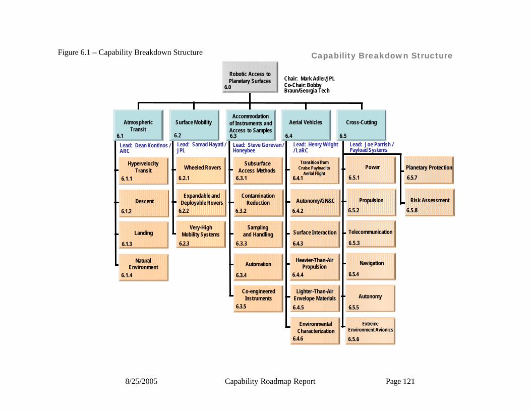
8/25/2005 Capability Roadmap Report Page 121
Capability Breakdown Structure
AtmosphericTransit
6.1
Lead: Dean Kontinos / ARC
HypervelocityTransit
6.1.1
6.1.2
Descent
Landing
6.1.3
6.1.4
NaturalEnvironment
Lead: Samad Hayati / JPL
Wheeled Rovers
6.2.1
6.2.2
Expandable andDeployable Rovers
Very-HighMobility Systems
6.2.3
Lead: Steve Gorevan / Honeybee
SubsurfaceAccess Methods
6.3.1
6.3.2
ContaminationReduction
Samplingand Handling
6.3.3
6.3.4
Automation
Lead: Henry Wright / LaRC
Transition fromCruise Payload to
Aerial Flight6.4.1
6.4.2
Autonomy/GN&C
Surface Interaction
6.4.3
6.4.4
Heavier-Than-AirPropulsion
Lead: Joe Parrish / Payload Systems
Power
6.5.1
6.5.2
Propulsion
Telecommunication
6.5.3
6.5.4
Navigation
6.2 6.3 6.4 6.5
Surface MobilityAccommodation
of Instruments andAccess to Samples
Aerial Vehicles Cross-Cutting
Lighter-Than-AirEnvelope Materials
6.4.5
6.4.6
EnvironmentalCharacterization
Autonomy
6.5.5
6.5.6
ExtremeEnvironment Avionics
Robotic Access to Planetary Surfaces Chair: Mark Adler/JPL
Co-Chair: Bobby Braun/Georgia Tech
Planetary Protection
6.5.7
6.5.8
Risk Assessment
6.0
6.3.5
Co-engineeredInstruments
Figure 6.1 – Capability Breakdown Structure

8/25/2005 Capability Roadmap Report Page 122
6.2.4 Roadmap Logic The capability roadmap in this report is a summary level roadmap. This summary level roadmap includes only a roll up of the key sub-capabilities milestone readiness to support a particular mission requirement. Detailed sub-capability and technology roadmaps showing the technology progression and sub-capability development were presented to the NAS and are available in the document sharing system. In the top blue banner of the roadmap, there are those key missions that are pertinent to the roadmap among those derived from the April 15, 2005 interim document delivered by the strategic roadmaps and displayed in the CRM Planning Milestones Chart. The green banner below represents a summary rollup of key capabilities from each of the various capability breakdown structure elements. The peach colored swim-lanes represent the individual top level capability breakdown structure element and the sub-capabilities within this roadmap. The triangles represent the date that the capability is ready to support a given mission, and the diamonds represent decision points. 6.2.5 Roadmap Examples The roadmaps shown in Figures 6.2a and 6.2b provide examples of how the capability development might be laid out for a specific set of assumed missions and mission launch dates. Your mileage may vary.

8/25/2005 Capability Roadmap Report Page 123
Figure 6.2a –
Capability Roadmap: Robotic Access to Planetary Surfaces (RAPS)
6.1 Atmosphere Transit
6.0 Robotics Access to Planetary Surfaces Capability Road Map(Key Events/Milestones)
2005 2010 20202015
Key Exploration Architectural Assumptions
6.2 Surface Mobility
6.3 Accommodation of Instruments & Access to Samples
6.4 Aerial Vehicles
6.5 Cross Cutting
Solar Cell Efficiency, Nuclear Power, Energy StorageSmall Throttleable Rocket EnginesBlack Boxes, Local Wireless CommunicationNavigation Beacons, Visual LocationFault Isolation & RecoveryTemperature, Pressure, Radiation, AccelerationSpacecraft Sterilization, CleaningAssured Sample Containment In transit
Probabilistic Risk Assessment, Risk Communication
Pinpoint Landing
Lunar 2nd
Mission
Lunar Pinpoint Landing
Subsurface Access 10cm
Mars Balloon Rigid Wing Pilot Control Rocket Propulsion
Ascpetic Sample / Caching
ImprMobility
Subsurface Access 1m
Subsurface Access 1m
Titan bal Navigator Pilot Lander Sampler
Interaction
Hyperguide
Aerothermo Modeling
Earth TPS
Supersonic Parachute
Subsurface Access 10m
Clean Sample Sub Sample Down Hole
Balloon Materials for Venus
Mars EDL
MSR
Titan Expl
Subsonic SteerableChute
Gas Giant TPS
Europa Lander
Free Mobility
Venus Surface
AFL / Deep Drill
Long Free Path Mobility
Deploy Aero
Jupiter Probes
Deploy Aero
Subsurface 100m
Subsurface 100m
Sample Handling on Earth
Capability/Subcapability/Major Accomplishment
Capability/Subcapability/Demonstrated or
established
CRM Milestone/Mission
Major Decision
Range of Dates
Development Timelines
Legend

8/25/2005 Capability Roadmap Report Page 124
Capability Roadmap: Robotic Access to Planetary Surfaces (RAPS)
6.1 Atmosphere Transit
6.0 Robotics Access to Planetary Surfaces Capability Road Map(Key Events/Milestones)
2020 2025 20352030
Key Exploration Architectural Assumptions
Neptune Orbiter
Inflatable Wing
6.2 Surface Mobility
6.3 Accommodation of Instruments & Access to Samples
6.4 Aerial Vehicles
6.5 Cross Cutting
VTOL Propulsion
Subsurface 1KM
Walking / Climbing / Propelling
High Rate Mobility
Propeller Propulsion
Mach 3+ Decelerator
Hard Landers
Hard Landers
Inflatable Wing
VSR
Subsurface 1 KM
Walking / Climbing / Repelling
Mach 3+ Decelerator
VTOL Propulsion
Solar Cell Efficiency, Nuclear Power, Energy StorageSmall Throttleable Rocket Engines
Navigation Beacons, Visual Location
Temperature, Pressure, Radiation, Acceleration
Assured Sample Containment In transit
Probabilistic Risk Assessment, Risk CommunicationSample Handling on Earth
Black Boxes, Local Wireless Communication
Fault Isolation & Recovery
Spacecraft Sterilization, Cleaning
Capability/Subcapability/Major Accomplishment
Capability/Subcapability/Demonstrated or
established
CRM Milestone/Mission
Major Decision
Range of Dates
Development Timelines
Legend
Capability/Subcapability/Major Accomplishment
Capability/Subcapability/Demonstrated or
established
CRM Milestone/Mission
Major Decision
Range of Dates
Development Timelines
Legend
Figure 6.2b

8/25/2005 Capability Roadmap Report Page 125
6.2.6 Near-Term Capability Developments To aid the decision maker reading this document, these are the capabilities that were identified as requiring immediate development in order to support the mission timeline assumed in this study:
1. Thermal protection system materials, test, analysis, and modeling 2. Supersonic parachute for Mars 3. High performance terrain sensing (both RADAR and visual terrain recognition) 4. Surface sample aseptic collection, handling, and caching 5. Spacecraft sterilization and cleaning 6. Assured containment of returned samples 7. Mid-air transition from stowed to flying airships 8. Improved wheeled mobility systems
6.2.7 Capabilities Assessment RAPS capabilities are broken into five major areas, each covered in their own section below. They are: Atmospheric Transit (land), Surface Mobility (rove), Accommodation of Instruments and Samples (dig), Aerial Vehicles (fly), and Cross-Cutting. 6.2.7.1 Atmospheric Transit Hypervelocity entry systems will need to support higher entry speeds, larger more massive entry systems, and precision landing. This in turn requires advancement in traditional rigid aeroshells, and development of new deployable systems. For rigid aeroshells it is required to reinvigorate the ablative thermal protection system capability, in hardware, facilities, and personnel. Critical technology gaps exist from mid-density to high-density ablators. Additional technology development is required in aerothermodynamic and aerodynamic prediction, and guidance-navigation-control. Deployable/inflatable aeroshells provide an alternative to traditional rigid aeroshell systems so that a large drag area can be packaged within a small volume for launch, and then be deployed without complex in-space assembly operations. For transonic deceleration, an increase in allowable Mach number over 2.3 and supersonic parachute drag area over 140 m2 is necessary for Mars landers greater than ~1000 kg entry mass. Continued advancements in subsonic parachutes would enable increased mass capabilities (i.e. clustering) and pinpoint landing capabilities (wind drift compensation and guidance/steering systems). The skycrane terminal descent system currently being developed for the Mars Science Laboratory mission has broad application to other landed missions and additional investments should be made to ensure that its full capability is explored and made available to future missions. High deceleration penetrators and impactors and their payloads require new development. High performance sensing is vital to increasing the reliability and performance of landing systems, for both RADAR systems and visual terrain recognition for pinpoint landing and hazard avoidance.
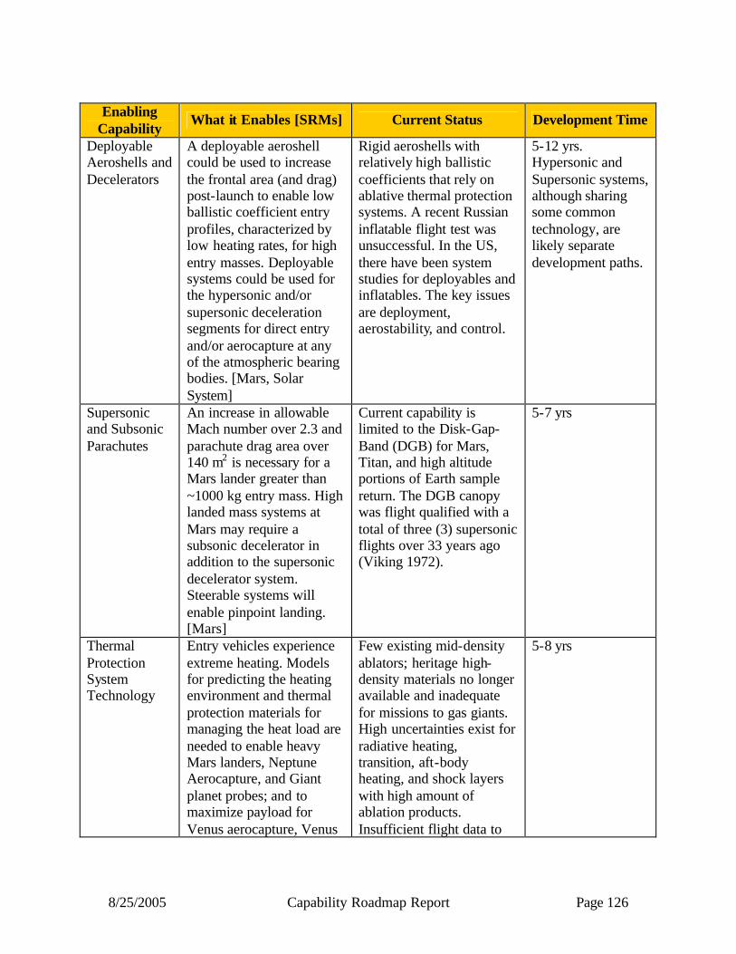
8/25/2005 Capability Roadmap Report Page 126
Enabling
Capability What it Enables [SRMs] Current Status Development Time
Deployable Aeroshells and Decelerators
A deployable aeroshell could be used to increase the frontal area (and drag) post-launch to enable low ballistic coefficient entry profiles, characterized by low heating rates, for high entry masses. Deployable systems could be used for the hypersonic and/or supersonic deceleration segments for direct entry and/or aerocapture at any of the atmospheric bearing bodies. [Mars, Solar System]
Rigid aeroshells with relatively high ballistic coefficients that rely on ablative thermal protection systems. A recent Russian inflatable flight test was unsuccessful. In the US, there have been system studies for deployables and inflatables. The key issues are deployment, aerostability, and control.
5-12 yrs. Hypersonic and Supersonic systems, although sharing some common technology, are likely separate development paths.
Supersonic and Subsonic Parachutes
An increase in allowable Mach number over 2.3 and parachute drag area over 140 m2 is necessary for a Mars lander greater than ~1000 kg entry mass. High landed mass systems at Mars may require a subsonic decelerator in addition to the supersonic decelerator system. Steerable systems will enable pinpoint landing. [Mars]
Current capability is limited to the Disk-Gap-Band (DGB) for Mars, Titan, and high altitude portions of Earth sample return. The DGB canopy was flight qualified with a total of three (3) supersonic flights over 33 years ago (Viking 1972).
5-7 yrs
Thermal Protection System Technology
Entry vehicles experience extreme heating. Models for predicting the heating environment and thermal protection materials for managing the heat load are needed to enable heavy Mars landers, Neptune Aerocapture, and Giant planet probes; and to maximize payload for Venus aerocapture, Venus
Few existing mid-density ablators; heritage high-density materials no longer available and inadequate for missions to gas giants. High uncertainties exist for radiative heating, transition, aft-body heating, and shock layers with high amount of ablation products. Insufficient flight data to
5-8 yrs
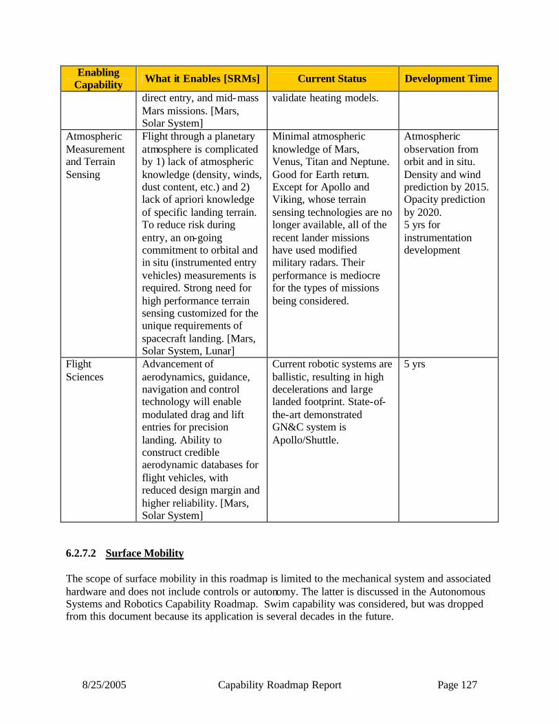
8/25/2005 Capability Roadmap Report Page 127
Enabling Capability What it Enables [SRMs] Current Status Development Time
direct entry, and mid-mass Mars missions. [Mars, Solar System]
validate heating models.
Atmospheric Measurement and Terrain Sensing
Flight through a planetary atmosphere is complicated by 1) lack of atmospheric knowledge (density, winds, dust content, etc.) and 2) lack of apriori knowledge of specific landing terrain. To reduce risk during entry, an on-going commitment to orbital and in situ (instrumented entry vehicles) measurements is required. Strong need for high performance terrain sensing customized for the unique requirements of spacecraft landing. [Mars, Solar System, Lunar]
Minimal atmospheric knowledge of Mars, Venus, Titan and Neptune. Good for Earth return. Except for Apollo and Viking, whose terrain sensing technologies are no longer available, all of the recent lander missions have used modified military radars. Their performance is mediocre for the types of missions being considered.
Atmospheric observation from orbit and in situ. Density and wind prediction by 2015. Opacity prediction by 2020. 5 yrs for instrumentation development
Flight Sciences
Advancement of aerodynamics, guidance, navigation and control technology will enable modulated drag and lift entries for precision landing. Ability to construct credible aerodynamic databases for flight vehicles, with reduced design margin and higher reliability. [Mars, Solar System]
Current robotic systems are ballistic, resulting in high decelerations and large landed footprint. State-of-the-art demonstrated GN&C system is Apollo/Shuttle.
5 yrs
6.2.7.2 Surface Mobility The scope of surface mobility in this roadmap is limited to the mechanical system and associated hardware and does not include controls or autonomy. The latter is discussed in the Autonomous Systems and Robotics Capability Roadmap. Swim capability was considered, but was dropped from this document because its application is several decades in the future.

8/25/2005 Capability Roadmap Report Page 128
For traverse on natural rough terrain, speed and lifetime need to be improved through configurations with greater mean-free path (MFP) to the next obstacle or hazard (landing site dependent), with better navigation sensors and increased computer throughput for faster path decisions, and with long-life actuators for driving and steering. Expandable rovers can greatly increase MFP, as well as potentially provide floatation for possible liquid or soft environments such as Titan. For traverse on steep slopes or extremely rough terrain not suitable for wheeled vehicles, new approaches to develop robotic walking and rappelling systems need to be developed. Enabling Capability What it Enables [SRMs] Current Status Development
Time Improved Wheeled Mobility Platforms
Ability to execute more sophisticated autonomous rover algorithms by the added computing power and navigation sensors. Also, enables longer lasting and electro-mechanically less complex rover hardware, which adds to the system's robustness [Mars, Lunar]
Six wheeled rovers have reached CRL 7 for a certain class of rovers, but their design is very complex, cannot survive Martian climate without complex and expensive protection, and are not very autonomous, partially because their computation power is very limited.
5-10 yrs
Expandable Rovers
In order to increase the mean free path (MFP) of rovers and still keep the stowed volume small, deployable rovers can be developed. One particular implementation is rovers with inflatable wheels [Mars, Lunar]
Technology of inflatable wheeled rovers has been developed to CRL 3-4. These prototype rovers have been deployed in the field and have shown to perform well in sand, rocky terrain, and on water.
5 yrs, CRL from 4 to 6; to use these platforms for in situ exploration require 5 more yrs
Walking, Rappelling, Hopping Mobility Systems
Objective is to develop mobility systems that can provide the capability to explore very difficult to access regions on planetary surfaces (such as gullies and cliffs and very rough terrain) [Mars, Lunar]
Prototype systems have been developed to demonstrate the principals of these types of mobility systems. These prototypes are at very low CRLs (1-2).
15 yrs to CRL 6 (in three phases of 5 yrs each)
6.2.7.3 Accommodation of Instruments and Samples Technology transfer from established Earth drilling techniques to planetary drilling is very limited, due to mass, power, volume, and time constraints, as well as extreme environments.

8/25/2005 Capability Roadmap Report Page 129
New drill bit designs must be developed to leverage low power and thrust/torque sinks. With no operator support on planetary surfaces, reliable electromechanical bit change-out systems must be incorporated to accommodate multiple borehole sorties. For penetration to take place, cuttings must be removed from the borehole with new designs compatible with automated operations. Ingenious means of reacting thrust and torque loads, perhaps from mobile platforms, must be devised. For depths below 20 meters, boreholes must be stabilized in novel ways that minimize mass. Punishing duty cycles imposed on long duration missions require drilling systems to be built from new and robust materials. Access to pristine samples will require localized bio-barriers for drills and bits must be implemented and in situ decontamination systems may be required. Cross contamination mitigation is necessary to ensure the integrity of sample analysis. Sampling system chambers and staging areas must be cleaned in situ to prevent cuttings from one sample being transferred for analysis with other samples. Surface drilling, crushing and sieving systems must be designed to minimize contamination of samples from lubrication and other materials. These processing actions must also minimize the loss of volatiles. Pristine sample access may only be attainable by transporting instrumentation down the borehole requiring the development of new co-engineered systems of instruments with drills. A drill capable of accessing 10s of meters to kilometers will encounter different materials such as regolith, rock, ice or combinations of these materials in unknown configurations, each requiring different operational approaches to penetration, chip transport, wall integrity and sample acquisition. To diagnose the state or fault mode, systems will require a range of embedded sensors to determine weight on bit, torque on bit, temperature and vibration. This telemetry needs to be synthesized, analyzed and used for autonomous real-time planning. Faults and failures must be diagnosed rapidly and recovery modes must be planned and implemented, without the intervention of human supervisors.
Enabling Capability
What it Enables [SRMs] Current Status Development Time
Subsurface Access (defeating and removing material, reacting loads, and maintaining borehole integrity)
Acquisition of samples from mm to km depths and in situ borehole analysis [Mars, Solar System]
Surface abrasion (TRL 9); 2.5 to 10 cm drilling/coring (TRL 5); 1 meter (TRL 5); 10 meters (TRL 4/5); 100 meter (TRL 3); 1 km (TRL 2)
2.5 to 10 cm drilling/coring 1 yr; 1 meter +2 yrs; 10 meters +3 yrs; 100 meter +10 yrs; 1 km +10 yrs
In Situ Contamination Reduction (forward, cross and back)
(1) Integrity of sample and borehole analysis, (2) protection of environments under investigation, (3) in situ bio-barriers, (4) breaking sample transfer
In situ decontamination technologies have not been well defined and developed (TRL 1-2)
9 yrs
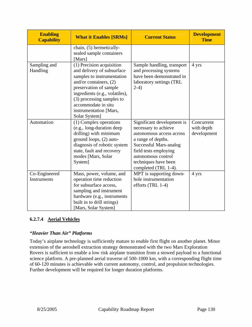
8/25/2005 Capability Roadmap Report Page 130
Enabling Capability What it Enables [SRMs] Current Status Development
Time
chain, (5) hermetically-sealed sample containers [Mars]
Sampling and Handling
(1) Precision acquisition and delivery of subsurface samples to instrumentation and/or containers, (2) preservation of sample ingredients (e.g., volatiles), (3) processing samples to accommodate in situ instrumentation [Mars, Solar System]
Sample handling, transport and processing systems have been demonstrated in laboratory settings (TRL 2-4)
4 yrs
Automation (1) Complex operations (e.g., long-duration deep drilling) with minimum ground loops, (2) auto-diagnosis of robotic system state, fault and recovery modes [Mars, Solar System]
Significant development is necessary to achieve autonomous access across a range of depths. Successful Mars-analog field tests employing autonomous control techniques have been completed (TRL 1-4).
Concurrent with depth development
Co-Engineered Instruments
Mass, power, volume, and operation time reduction for subsurface access, sampling and instrument hardware (e.g., instruments built in to drill strings) [Mars, Solar System]
MPT is supporting down-hole instrumentation efforts (TRL 1-4)
4 yrs
6.2.7.4 Aerial Vehicles
“Heavier Than Air” Platforms
Today’s airplane technology is sufficiently mature to enable first flight on another planet. Minor extension of the aeroshell extraction strategy demonstrated with the two Mars Exploration Rovers is sufficient to enable a low risk airplane transition from a stowed payload to a functional science platform. A pre-planned aerial traverse of 500-1000 km, with a corresponding flight time of 60-120 minutes is achievable with current autonomy, control, and propulsion technologies. Further development will be required for longer duration platforms.
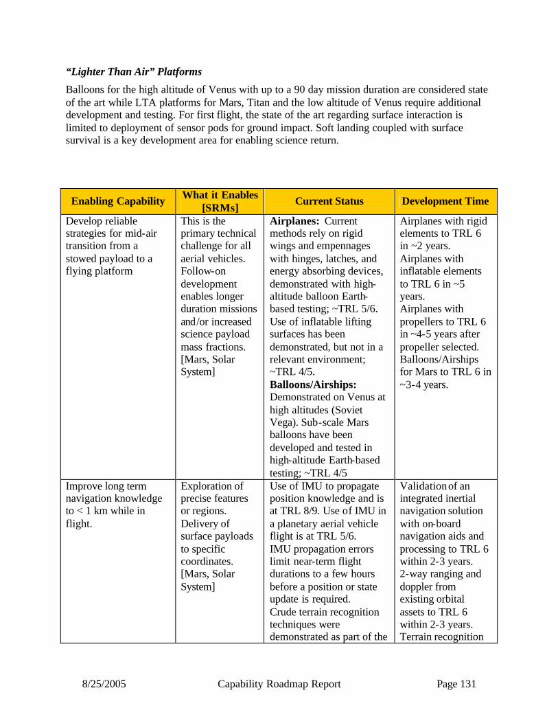
8/25/2005 Capability Roadmap Report Page 131
“Lighter Than Air” Platforms
Balloons for the high altitude of Venus with up to a 90 day mission duration are considered state of the art while LTA platforms for Mars, Titan and the low altitude of Venus require additional development and testing. For first flight, the state of the art regarding surface interaction is limited to deployment of sensor pods for ground impact. Soft landing coupled with surface survival is a key development area for enabling science return.
Enabling Capability What it Enables [SRMs]
Current Status Development Time
Develop reliable strategies for mid-air transition from a stowed payload to a flying platform
This is the primary technical challenge for all aerial vehicles. Follow-on development enables longer duration missions and/or increased science payload mass fractions. [Mars, Solar System]
Airplanes: Current methods rely on rigid wings and empennages with hinges, latches, and energy absorbing devices, demonstrated with high-altitude balloon Earth-based testing; ~TRL 5/6. Use of inflatable lifting surfaces has been demonstrated, but not in a relevant environment; ~TRL 4/5. Balloons/Airships: Demonstrated on Venus at high altitudes (Soviet Vega). Sub-scale Mars balloons have been developed and tested in high-altitude Earth-based testing; ~TRL 4/5
Airplanes with rigid elements to TRL 6 in ~2 years. Airplanes with inflatable elements to TRL 6 in ~5 years. Airplanes with propellers to TRL 6 in ~4-5 years after propeller selected. Balloons/Airships for Mars to TRL 6 in ~3-4 years.
Improve long term navigation knowledge to < 1 km while in flight.
Exploration of precise features or regions. Delivery of surface payloads to specific coordinates. [Mars, Solar System]
Use of IMU to propagate position knowledge and is at TRL 8/9. Use of IMU in a planetary aerial vehicle flight is at TRL 5/6. IMU propagation errors limit near-term flight durations to a few hours before a position or state update is required. Crude terrain recognition techniques were demonstrated as part of the
Validation of an integrated inertial navigation solution with on-board navigation aids and processing to TRL 6 within 2-3 years. 2-way ranging and doppler from existing orbital assets to TRL 6 within 2-3 years. Terrain recognition
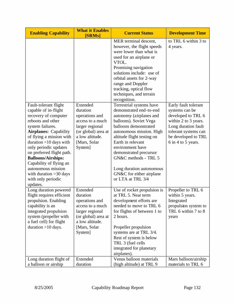
8/25/2005 Capability Roadmap Report Page 132
Enabling Capability What it Enables [SRMs] Current Status Development Time
MER terminal descent, however, the flight speeds were lower than what is used for an airplane or VTOL. Promising navigation solutions include: use of orbital assets for 2-way range and Doppler tracking, optical flow techniques, and terrain recognition.
to TRL 6 within 3 to 4 years.
Fault-tolerant flight capable of in-flight recovery of computer reboots and other system failures. Airplanes: Capability of flying a mission with duration >10 days with only periodic updates on preferred flight path. Balloons/Airships: Capability of flying an autonomous mission with duration >30 days with only periodic updates.
Extended duration operations and access to a much larger regional (or global) area at a low altitude. [Mars, Solar System]
Terrestrial systems have demonstrated end-to-end autonomy (airplanes and balloons). Soviet Vega balloons demonstrated autonomous mission. High altitude flight testing on Earth in relevant environment have demonstrated precursor GN&C methods - TRL 5 Long duration autonomous GN&C for either airplane or LTA at TRL 3/4
Early fault tolerant systems can be developed to TRL 6 within 2 to 3 years. Long duration fault tolerant systems can be developed to TRL 6 in 4 to 5 years.
Long duration powered flight requires efficient propulsion. Enabling capability is an integrated propulsion system (propeller with a fuel cell) for flight duration >10 days.
Extended duration operations and access to a much larger regional (or global) area at a low altitude. [Mars, Solar System]
Use of rocket propulsion is at TRL 5. Near term development efforts are needed to move to TRL 6 for flights of between 1 to 2 hours. Propeller propulsion systems are at TRL 3/4. Rest of system is below TRL 3 (fuel cells integrated for planetary airplanes).
Propeller to TRL 6 within 5 years. Integrated propulsion system to TRL 6 within 7 to 8 years
Long duration flight of a balloon or airship
Extended duration
Venus balloon materials (high altitude) at TRL 9
Mars balloon/airship materials to TRL 6
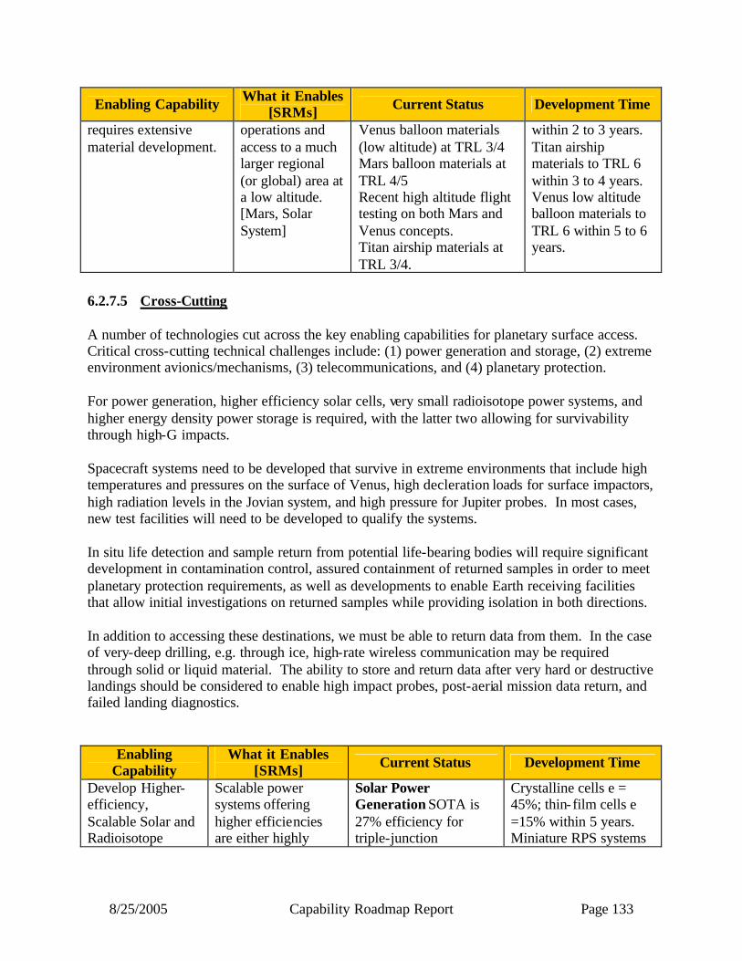
8/25/2005 Capability Roadmap Report Page 133
Enabling Capability What it Enables [SRMs] Current Status Development Time
requires extensive material development.
operations and access to a much larger regional (or global) area at a low altitude. [Mars, Solar System]
Venus balloon materials (low altitude) at TRL 3/4 Mars balloon materials at TRL 4/5 Recent high altitude flight testing on both Mars and Venus concepts. Titan airship materials at TRL 3/4.
within 2 to 3 years. Titan airship materials to TRL 6 within 3 to 4 years. Venus low altitude balloon materials to TRL 6 within 5 to 6 years.
6.2.7.5 Cross-Cutting A number of technologies cut across the key enabling capabilities for planetary surface access. Critical cross-cutting technical challenges include: (1) power generation and storage, (2) extreme environment avionics/mechanisms, (3) telecommunications, and (4) planetary protection. For power generation, higher efficiency solar cells, very small radioisotope power systems, and higher energy density power storage is required, with the latter two allowing for survivability through high-G impacts. Spacecraft systems need to be developed that survive in extreme environments that include high temperatures and pressures on the surface of Venus, high decleration loads for surface impactors, high radiation levels in the Jovian system, and high pressure for Jupiter probes. In most cases, new test facilities will need to be developed to qualify the systems. In situ life detection and sample return from potential life-bearing bodies will require significant development in contamination control, assured containment of returned samples in order to meet planetary protection requirements, as well as developments to enable Earth receiving facilities that allow initial investigations on returned samples while providing isolation in both directions. In addition to accessing these destinations, we must be able to return data from them. In the case of very-deep drilling, e.g. through ice, high-rate wireless communication may be required through solid or liquid material. The ability to store and return data after very hard or destructive landings should be considered to enable high impact probes, post-aerial mission data return, and failed landing diagnostics.
Enabling Capability
What it Enables [SRMs] Current Status Development Time
Develop Higher-efficiency, Scalable Solar and Radioisotope
Scalable power systems offering higher efficiencies are either highly
Solar Power Generation SOTA is 27% efficiency for triple-junction
Crystalline cells e = 45%; thin-film cells e =15% within 5 years. Miniature RPS systems
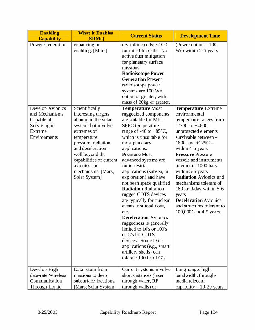
8/25/2005 Capability Roadmap Report Page 134
Enabling Capability
What it Enables [SRMs] Current Status Development Time
Power Generation enhancing or enabling. [Mars]
crystalline cells; <10% for thin-film cells. No active dust mitigation for planetary surface missions. Radioisotope Power Generation Present radioisotope power systems are 100 We output or greater, with mass of 20kg or greater.
(Power output = 100 We) within 5-6 years
Develop Avionics and Mechanisms Capable of Surviving in Extreme Environments
Scientifically interesting targets abound in the solar system, but involve extremes of temperature, pressure, radiation, and deceleration – well beyond the capabilities of current avionics and mechanisms. [Mars, Solar System]
Temperature Most ruggedized components are suitable for MIL-SPEC temperature range of -40 to +85°C, which is unsuitable for most planetary applications. Pressure Most advanced systems are for terrestrial applications (subsea, oil exploration) and have not been space qualified Radiation Radiation-rugged COTS devices are typically for nuclear events, not total dose, etc. Deceleration Avionics ruggedness is generally limited to 10's or 100's of G's for COTS devices. Some DoD applications (e.g., smart artillery shells) can tolerate 1000’s of G’s
Temperature Extreme environmental temperature ranges from -270C to +460C; unprotected elements survivable between -180C and +125C – within 4-5 years Pressure Pressure vessels and instruments tolerant of 1000 bars within 5-6 years Radiation Avionics and mechanisms tolerant of 180 krad/day within 5-6 years Deceleration Avionics and structures tolerant to 100,000G in 4-5 years.
Develop High-data-rate Wireless Communication Through Liquid
Data return from missions to deep subsurface locations. [Mars, Solar System]
Current systems involve short distances (laser through water, RF through walls) or
Long-range, high-bandwidth, through-media telecom capability – 10-20 years.

8/25/2005 Capability Roadmap Report Page 135
Enabling Capability
What it Enables [SRMs] Current Status Development Time
and Solid Materials extremely low bandwidth. High bandwidth long-distance wireless communication through liquids and solids does not currently exist.
Develop Robust Onboard Data Storage and Strategies for Post-Mission Data Delivery
Data return from missions where a controlled landing or (other end to mission) is not ensured. [Mars, Solar System]
Crashworthy (Black box) technology has not been miniaturized, nor has it been coupled to extremely robust, self-powered communication capability
Integrated data recording/ telecommunication package for small missions – 4-5 years
Provide Forward and Back Planetary Protection for Missions to Potentially Biologically Active Areas
Missions to, and returned samples from, regions of potential biological activity. [Mars, Solar System]
Planetary protection levels IV-C and V are not readily achievable with current technology; i.e., sterilization at the spacecraft level, sterilization of modern materials and avionics, and handling of potentially biohazardous returned samples
Advanced sterilization methods can reach TRL 6 in 3-4 years. Returned sample handling can be developed in 5-6 years.
6.2.8 Relationship to Other Roadmaps Following are the relationships with the other capability roadmaps. The key relationships are shown in italics.
• High Energy Power and Propulsion: RAPS assumes the provision of nuclear power systems, both in the 100 We class and the < 1 We class.
• In-Space Transportation: RAPS assumes the provision of ascent and autonomous rendezvous and capture systems for sample returns, RAPS provides aerocapture.
• Advanced Telescopes and Observatories: No relation. Remote observations of planetary atmospheres and surfaces may provide engineering and operational information for entry, descent, and landing systems.

8/25/2005 Capability Roadmap Report Page 136
• Communications and Navigation: RAPS assumes the provision of relay radios and services for low-energy data transmission, radio-navigation data types, and frequent access to surface assets.
• Human Planetary Landing Systems: RAPS provides ground-based test facilities, high-altitude Earth test infrastructure, sustained environmental observation, visual terrain recognition, and hypersonic guidance experience, as well as an experienced cadre of Mars landing practitioners. In the long run, RAPS would benefit significantly from the increased landed mass capability of the one-tenth scale human landing demonstration systems.
• Human Health and Support Systems: No relation. • Human Exploration Systems and Mobility: No relation. Robotic assistants to humans
are covered in HESM, not RAPS. • Autonomous Systems and Robotics: RAPS assumes the provision of high-level autonomy
for surface and aerial exploration systems, in particular for mobility to targets, articulation and surface interaction at targets, and goal-oriented resource management.
• Transformational Spaceport/Range Technologies: No relation. • Scientific Instruments and Sensors: RAPS provides surface and atmospheric access to
in situ instruments and sensors, and assumes the provision of downhole instrumentation integrated with deep drilling systems.
• In Situ Resource Utilization: No relation. Robotic mining and resource extraction equipment are covered in ISRU and HESM, not in RAPS.
• Advanced Modeling, Simulation, and Analysis: RAPS assumes the provision of detailed environmental and system simulation capabilities, including the direct incorporation of flight software, for design and verification.
• Systems Engineering Cost/Risk Analysis: RAPS assumes the provision of established practices applicable to these systems for probabilistic risk assessment where such analyses are required to validate compliance with planetary protection requirements.
• Nanotechnology: RAPS does not assume but may benefit from the provision of nanostructured thermal protection materials, and from nanoelectronics and nanosensors to enable small entry probes.
6.2.9 Infrastructure Robotic access technology development and flight system qualification requires access to numerous unique facilities across the country as well as support of the resident engineering talent that has honed a unique skill set. A small set of facilities exist which are vital for RAPS applications. Most of these same facilities also have direct application to the Human Planetary Landing Systems Capability Roadmap. No ground-based facility exactly replicates high energy flight conditions. Instead, individual facilities have been developed that replicate a particular aspect of hypervelocity flight. When combined with analysis and flight test capabilities (e.g., sub-orbital balloon and sounding rocket programs), these ground-based facilities anchor robotic access technology development and flight system qualification.
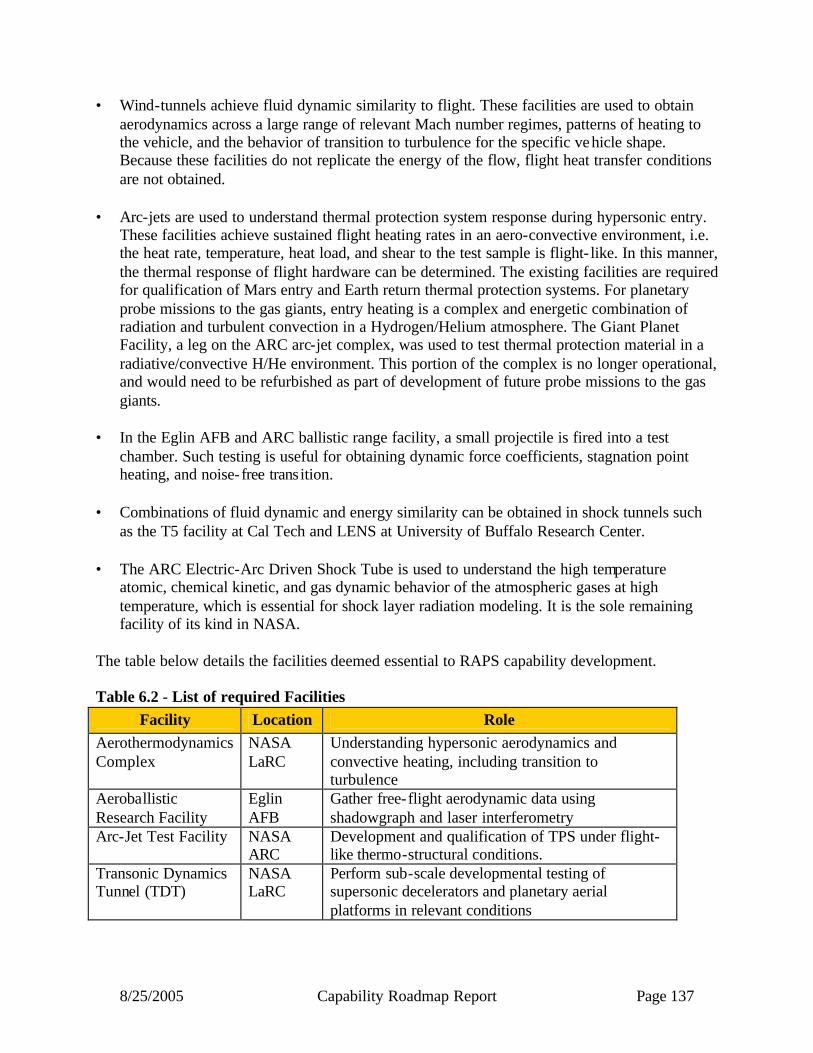
8/25/2005 Capability Roadmap Report Page 137
• Wind-tunnels achieve fluid dynamic similarity to flight. These facilities are used to obtain aerodynamics across a large range of relevant Mach number regimes, patterns of heating to the vehicle, and the behavior of transition to turbulence for the specific vehicle shape. Because these facilities do not replicate the energy of the flow, flight heat transfer conditions are not obtained.
• Arc-jets are used to understand thermal protection system response during hypersonic entry.
These facilities achieve sustained flight heating rates in an aero-convective environment, i.e. the heat rate, temperature, heat load, and shear to the test sample is flight- like. In this manner, the thermal response of flight hardware can be determined. The existing facilities are required for qualification of Mars entry and Earth return thermal protection systems. For planetary probe missions to the gas giants, entry heating is a complex and energetic combination of radiation and turbulent convection in a Hydrogen/Helium atmosphere. The Giant Planet Facility, a leg on the ARC arc-jet complex, was used to test thermal protection material in a radiative/convective H/He environment. This portion of the complex is no longer operational, and would need to be refurbished as part of development of future probe missions to the gas giants.
• In the Eglin AFB and ARC ballistic range facility, a small projectile is fired into a test
chamber. Such testing is useful for obtaining dynamic force coefficients, stagnation point heating, and noise-free transition.
• Combinations of fluid dynamic and energy similarity can be obtained in shock tunnels such
as the T5 facility at Cal Tech and LENS at University of Buffalo Research Center. • The ARC Electric-Arc Driven Shock Tube is used to understand the high temperature
atomic, chemical kinetic, and gas dynamic behavior of the atmospheric gases at high temperature, which is essential for shock layer radiation modeling. It is the sole remaining facility of its kind in NASA.
The table below details the facilities deemed essential to RAPS capability development. Table 6.2 - List of required Facilities
Facility Location Role Aerothermodynamics Complex
NASA LaRC
Understanding hypersonic aerodynamics and convective heating, including transition to turbulence
Aeroballistic Research Facility
Eglin AFB
Gather free-flight aerodynamic data using shadowgraph and laser interferometry
Arc-Jet Test Facility NASA ARC
Development and qualification of TPS under flight-like thermo-structural conditions.
Transonic Dynamics Tunnel (TDT)
NASA LaRC
Perform sub-scale developmental testing of supersonic decelerators and planetary aerial platforms in relevant conditions
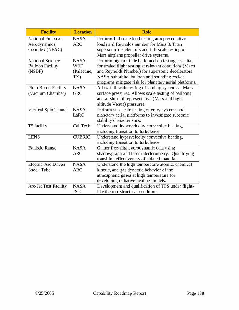
8/25/2005 Capability Roadmap Report Page 138
Facility Location Role National Full-scale Aerodynamics Complex (NFAC)
NASA ARC
Perform full-scale load testing at representative loads and Reynolds number for Mars & Titan supersonic decelerators and full-scale testing of Mars airplane propeller drive systems.
National Science Balloon Facility (NSBF)
NASA WFF (Palestine, TX)
Perform high altitude balloon drop testing essential for scaled flight testing at relevant conditions (Mach and Reynolds Number) for supersonic decelerators. NASA suborbital balloon and sounding rocket programs mitigate risk for planetary aerial platforms.
Plum Brook Facility (Vacuum Chamber)
NASA GRC
Allow full-scale testing of landing systems at Mars surface pressures. Allows scale testing of balloons and airships at representative (Mars and high-altitude Venus) pressures.
Vertical Spin Tunnel NASA LaRC
Perform sub-scale testing of entry systems and planetary aerial platforms to investigate subsonic stability characteristics.
T5 facility Cal Tech Understand hypervelocity convective heating, including transition to turbulence
LENS CUBRIC Understand hypervelocity convective heating, including transition to turbulence
Ballistic Range NASA ARC
Gather free-flight aerodynamic data using shadowgraph and laser interferometry. Quantifying transition effectiveness of ablated materials.
Electric-Arc Driven Shock Tube
NASA ARC
Understand the high temperature atomic, chemical kinetic, and gas dynamic behavior of the atmospheric gases at high temperature for developing radiative heating models.
Arc-Jet Test Facility NASA JSC
Development and qualification of TPS under flight-like thermo-structural conditions.

8/25/2005 Capability Roadmap Report Page 139
6.3 Summary Entry, descent, and landing systems do not scale up in size gracefully, and so the continuing demand on more capable delivery systems will require capability development before such missions can be considered feasible. EDL and aerial vehicle development depend heavily on NASA test infrastructure and expertise — special attention is needed to determine how to maintain and enhance that infrastructure and critically skilled personnel. Small landers require the development of high-G systems and small nuclear power sources (RPS), which would enable a new class of low-cost network science missions to provide much broader surface coverage. Modest investments in capability developments can enable airship and airplane vehicles for Venus, Mars, and Titan and will enable a new class of science missions to be conceived and executed. For both landed and aerial missions, precursor environmental observations will enhance and possibly enable the design and test of future systems. How the systems perform in those environments need to be well characterized, analyzed, and fed-forward to reduce risk for subsequent missions. New surface mobility systems should be developed to access difficult and treacherous terrain. One example of such highly desirable targets is putative water gullies in Martian crater walls. Sampling capabilities will initially be driven and developed by missions. However, deep drilling and down-hole instrumentation require considerable development and demonstration before mission applications can be considered. Extreme environment systems are essential for the envisioned strategic missions. A comprehensive program should be put in place to perform the system engineering trades to define the requirements, and then develop the capabilities. Unprecedented degrees of contamination control for both science and planetary protection is required for life-detection missions, either in situ or via returned samples. In addition to the contamination control, the containment of Martian samples upon return to Earth must be assured to meet planetary protection requirements. Feasible planetary protection approaches must established before we can plan and cost a Mars Sample Return mission.

8/25/2005 Capability Roadmap Report Page 140
Acronym list AFB Air Force Base AFL Astrobiological Field Laboratory (Mars mission) ARC Ames Research Center CBS Capability Breakdown Structure COTS Commercial Off-The-Shelf CUBRC Calspan-University of Buffalo Research Center DGB Disk Gap Band (type of parachute) EDL Entry, Descent, and Landing G or g A force of one Earth gravity GN&C Guidance, Navigation, and Control GRC Glenn Research Center HESM Human Exploration Systems and Mobility IMU Inertial Measurement Unit ISRU In Situ Resource Utilization JPL Jet Propulsion Laboratory JSC Johnson Space Center Krad Kilorads of Radiation LENS Large Energy National Shock Tunnel LTA Lighter Than Air LaRC Langley Research Center MER Mars Exploration Rover MFP Mean Free Path MIL-SPEC Military Specification (for component temperature ranges) MPT Mars Program Technology MSR Mars Sample Return NASA National Aeronautics and Space Administration NFAC National Full-Scale Aerodynamics Facility NRC National Research Council NSBF National Science Balloon Facility PP Planetary Protection RAPS Robotic Access to Planetary Surfaces RF Radio Frequency RPS Radioisotope Power Source SOTA State of the Art SRM Strategic Roadmap TDT Transonic Dynamics Tunnel TPS Thermal Protection System TRL Technology Readiness Level VSR Venus Sample Return VTOL Vertical Take-Off and Landing WFF Wallops Flight Facility We Watts electric
8/25/2005 Capability Roadmap Report Page 141
NASA
Capability Road Map (CRM) 7
Human Planetary Landing Systems (HPLS)
Executive Summary
Chair: Rob Manning, JPL Co-Chair: Harrison Schmitt (ex-NASA)
Deputy Chair: Claude Graves, JSC
Team Members
NASA / JPL
James Arnold, NASA ARC Chris Cerimele, NASA JSC
Neil Cheatwood, NASA LaRC Juan Cruz, NASA LaRC Chirold Epp, NASA JSC Carl Guernsy, NASA JPL Kent Joosten, NASA JSC
Mary Kae Lockwood, NASA LaRC Michelle Monk, NASA MSFC
Dick Powell, NASA LaRC Ray Silvestri, NASA JSC Tom Rivellini, NASA JPL
Ethiraj (Raj) Venkatapathy, NASA ARC Barry (Butch) Wilmore, NASA JSC
Aron Wolf, NASA JPL
Academia
Bobby Braun, Ga Tech Ken Mease, UC Irvine
Industry
Glenn Brown, Vertigo
Jim Masciarelli, Ball Aerospace Bill Wilcockson, LMSS

8/25/2005 Capability Roadmaps Report Page 142
7 Human Planetary Landing Systems (Roadmap 7) 7.1 General Capability Overview 7.1.1 Capability Description The purpose of Human Planetary Landing Systems (HPLS) is to safely deliver human-scale piloted and unpiloted systems to the surface of Moon, Mars and Earth. Due to its unique and so far unexplored challenges, special emphasis was placed on the construction of a roadmap for the development of the system and ensemble of subsystems required to land on Mars. This roadmap defines a realizable plan for developing the capability to deliver the first cargo & piloted flights to the surface of Mars by 2032 with a “reasonable” mass starting at Low Earth Orbit (LEO). This Capability Roadmap defines the initial as well as long-term milestones needed to achieve that goal as well as to define the roadmap for addressing the key challenges and commonality with lunar and Earth return human exploration systems. This roadmap was developed by consensus of many (majority) of the Aerocapture, Entry Descent & Landing (AEDL) community within and outside of NASA and is consistent with the “The Vision for Space Exploration February 2004”. 7.1.2 Benefits The roadmap for development of lunar exploration landing systems may be strongly mirrored in the Apollo-era development story. Likewise the at least two historical Earth return capability developments (Apollo and Shuttle) provide a strong technological basis for new developments in these areas. While these developments are included in this roadmap, we do not provide additional detail that can not be obtained by looking at the historical record. However, there is no clear parallel for the development of human scale Mars landing systems. The challenges of developing Mars landing systems dwarf today’s challenges faced by developers of landing systems for the moon and Earth. A plan to address these challenges is essential to meet the goals set in the Vision for Space Exploration. Mars mission designs conceived to-date assume both the use of variations of hypersonic aero-assisted technology that was developed for Earth entry in the 1960’s and 1970’s as well as Apollo- like landing systems for the final kilometers. However the architectures and systems that enable the safe transition from use of Earth- like guided hypersonic decelerators to lunar- like terminal descent control has not yet been conceived. Aero-assist is an enabling, common element in most if not all Mars mission architectures. For example, studies show that with aero-assist (using as little retro-propulsion as possible), the landed mass on Mars may as large as 1/5th that departing from low Earth orbit. This is in contrast to 1/70th that would be delivered assuming traditional retro-propulsive systems and no drag from the thin Mars atmosphere (which is not physically possible).

8/25/2005 Capability Roadmaps Report Page 143
7.1.3 Key Architecture / Strategic Decisions
Key Architecture/Strategic Decisions Date Needed Impact of Decision on Capability
Determination of set of AEDL and Ascent system design options for detailed analysis and scaled Earth flight tests of key subsystems.
2008
Determines at least one design option to focus follow-on detailed design/test/risk assessment.
Determination of level of commonality or the Lunar & Mars System Design:
• Common landed payloads, • Mass and form factors, • Common habitat module, • Common descent propulsion, • Common Earth Return Vehicle.
2008 Determines possible constraints on the design of both Lunar and Mars systems.
Determination of level of commonality of Lunar & Mars Common Operational Approaches and/or verification of Mars Operational Approaches:
• Common orbital mission control, • Coordination of two landers per mission, • Common surface rendezvous operations, • Common crew size and skill mix, • Common controls and displays configuration and
operation, • Common communications delays, • Common navigational approaches to pinpoint
landings.
2010 Determines possible constraints on the planning of both Lunar and Mars flight operations.
• Determination of Mars Landing Site Access Max & Min MOLA Elevation.
• Max Latitude. • Accuracy (pin point landing) requirement.
Mars Atmosphere Requirements: • Max & Min Tau/dust loading.
Acceptable AEDL Risk Levels. Human environmental Requirements.
2010
Determines the needed capabilities for the AEDL& Ascent system for performance & Risk assessment. (Mars AEDL design highly affected by key design parameters).
Determination of Heavy Lift Launch Vehicle Capability and shroud volume / form factor. 2014
System Design & Packaging is dependent on mass, volume.
Determination of Mars Mission Delivery Architecture: • Number of Landers, • Abort modes, • Orbital mission control, • Surface rendezvous mode, • Payload Mass, Volume, Form Factor, • Quantity & Config. of Landed Assets, • Planetary Protection Requirements.
2015 System design is dependent on Mission design requirements.

8/25/2005 Capability Roadmaps Report Page 144
Key Architecture/Strategic Decisions Date Needed Impact of Decision on Capability
Determination of In-Space transportation propulsion mode (Fission, fusion, electric? Chemical?). 2015
Decides need for aerocapture vs. propulsive/aerobrake capture.
Decide method(s) for full scale AEDL & Ascent development testing including test and verification infrastructure development and specific lunar mission demonstration.
• Launch assets • Ground assets • Use of ISS and CEV
2015 Test and verification capabilities for full scale system will impact design decisions.
Determination of the physiological and human performance envelope and development methods for enhancing human performance after long term exposure to space environment stressors (artificial gravity, advanced control and display design, on-board training, enhanced human-automation interaction).
2015 Determines AEDL & Ascent Detailed Design and human/machine interaction.
Selection of AEDL & Ascent system design. 2015
This decision enables the initiation of the detailed design of the scaled model validation program as well as the full scale development program.
Decision on whether and how to launch scaled (1/10th?) AEDL & Ascent Model Validation Mars Test Flight in ’22 using EELV.
2016
This test program will retire certain key risks needed before finalization of the full scale design. (these tests do not replace the full scale at-Earth subsystem test programs).
Determination of need for robotic orbiter assets for communication & navigation enhancements and need for redundancy & coverage.
2020 System design parameters highly affected by landing location.

8/25/2005 Capability Roadmaps Report Page 145
7.1.4 Major Technical Challenges
The major technical challenges are associated with the delivery of large masses and volumes as well as humans to Mars orbit & surface and safe return of astronauts to Earth. These large masses are associated with human Mars descent/ascent vehicles, human habitats on Mars and in space transportation vehicles that transport the crew to and from Mars but must capture into orbit and dwell there unt il the return journey to Earth. Figure 7.1 indicates that the minimum Human Mission asset landed masses are may be in the range of 1-2 orders of magnitude greater than the touchdown masses of historical Mars landing systems. The disparity between the current Mars landing capability and the required capability for human missions is large.
Figure 7.1. Challenges of Landing on Mars
Source: NASA JSC/JPL However, there is no known “Aerocapture/Entry Descent & Landing” (AEDL) conceptual design (nor ensemble of high TRL technologies) in existence today that has the ability to safely deliver human scale missions to Mars. While there are many exciting options, significant work remains to determine which AEDL system will be able to do the job. What follows, Table 7.1, is a list of the top nine challenges and observations that the HPLS roadmap team has noted.
0.7 0.4 0.5 0.4 0.8 1.34.0
40.0 40.0
0.0
5.0
10.0
15.0
20.0
25.0
30.0
35.0
40.0
Mass (MT)
1976 1981 1986 1991 1996 2001 2006 2011 2016 2021 2026 2031Year
Mars Lander Touchdown Masses
Viking MPF MER MSL MSR
ScaledMarsFlightTest
Mars Cargo& FirstHumanLanding
PHX

8/25/2005 Capability Roadmaps Report Page 146
Table 7.1. Major Technical Challenges
2006-2010 • Landing systems architecture, guidance, control & configuration of a highly
integrated Mars surface delivery system that guides and decelerates from interplanetary velocities:
o to hypersonic, o to supersonic, o to subsonic, o to terminal descent (and possibly ascent as well), o to a pin-point landing.
• System architecture drivers and configuration for Mars mission-mode and abort-modes.
• Design and development of countermeasures and mitigation strategies (including human-centered landing and targeting interfaces, decision support systems for vehicle health and trajectory management, and the development of training protocols and operational procedure) for pilot performance degradation.
• Maintenance of US test facilities and development of personnel knowledgeable in human-rated landing systems.
2010 - 2020 • Terminal Descent Propulsion and pin point landing (terrain relative) sensing
& guidance systems (Moon Mars commanlity). • Aerocapture techniques into Mars or Earth orbit for low risk mass-reducing
design options. • Critical Systems design & Technology Gap between supersonic flight (Mach
2-5) and subsonic flight (Mach 0.6-0.8) where propulsive deceleration can start. Must develop:
o Large Supersonic Decelerator, o Very large supersonic parachutes (or other deployed decelerator), o Supersonic propulsive methods.
• Mass-efficient human-rated thermal protection systems and materials for large Mars and Earth-return aerocapture and entry systems. New deployable or inflatable systems may also be required.
2020 - 2030 • Validated models of Mars atmosphere density and wind models, which in turn
are affected by seasonal, diurnal, topographic, climate and dust storm models.
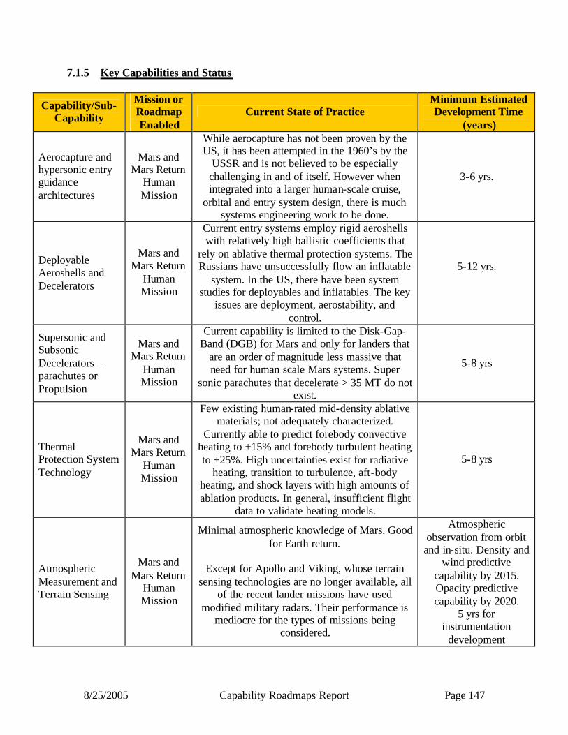
8/25/2005 Capability Roadmaps Report Page 147
7.1.5 Key Capabilities and Status
Capability/Sub-Capability
Mission or Roadmap Enabled
Current State of Practice Minimum Estimated Development Time
(years)
Aerocapture and hypersonic entry guidance architectures
Mars and Mars Return
Human Mission
While aerocapture has not been proven by the US, it has been attempted in the 1960’s by the
USSR and is not believed to be especially challenging in and of itself. However when integrated into a larger human-scale cruise,
orbital and entry system design, there is much systems engineering work to be done.
3-6 yrs.
Deployable Aeroshells and Decelerators
Mars and Mars Return
Human Mission
Current entry systems employ rigid aeroshells with relatively high ballistic coefficients that
rely on ablative thermal protection systems. The Russians have unsuccessfully flow an inflatable
system. In the US, there have been system studies for deployables and inflatables. The key
issues are deployment, aerostability, and control.
5-12 yrs.
Supersonic and Subsonic Decelerators – parachutes or Propulsion
Mars and Mars Return
Human Mission
Current capability is limited to the Disk-Gap-Band (DGB) for Mars and only for landers that
are an order of magnitude less massive that need for human scale Mars systems. Super
sonic parachutes that decelerate > 35 MT do not exist.
5-8 yrs
Thermal Protection System Technology
Mars and Mars Return
Human Mission
Few existing human-rated mid-density ablative materials; not adequately characterized.
Currently able to predict forebody convective heating to ±15% and forebody turbulent heating to ±25%. High uncertainties exist for radiative
heating, transition to turbulence, aft-body heating, and shock layers with high amounts of ablation products. In general, insufficient flight
data to validate heating models.
5-8 yrs
Atmospheric Measurement and Terrain Sensing
Mars and Mars Return
Human Mission
Minimal atmospheric knowledge of Mars, Good for Earth return.
Except for Apollo and Viking, whose terrain
sensing technologies are no longer available, all of the recent lander missions have used
modified military radars. Their performance is mediocre for the types of missions being
considered.
Atmospheric observation from orbit and in-situ. Density and
wind predictive capability by 2015. Opacity predictive capability by 2020.
5 yrs for instrumentation
development

8/25/2005 Capability Roadmaps Report Page 148
7.2 Roadmap Development 7.2.1 Legacy Activities and Roadmap Assumptions The CRM activities were based on the collective knowledge of the members of the roadmap team that were assembled which included a large proportion of the active AEDL population in the United States. The NASA Capability Requirements Analysis and Integration (CRAI) documentation was consulted to establish a baseline and the NASA Mars Human Design Reference Mission studies as well as other studies managed by the Johnson Space Center Exploration Office were also referenced to establish likely human vehicle requirements. The NASA February 2004 “Vision for Space Exploration” document was used as guidance for specific near term dates and overall strategy. Where the Vision lacked in detail, the products of the Strategic Road Map (SRM) teams were referenced and as a last resort HPLS specific milestones and strategies were assumed and documented as necessary. All assumed milestones can be found documented in this report in Fig’s 7.2a & 7.2b Roadmap rollup graphics. The interim reports (April 15, 2005) from the following SRM’s were used and referenced:
1) Robotic and Human Lunar Exploration, 2) Robotic and Human Exploration of Mars, 5) Exploration Transportation System, 6) International Space Station, 7) Space Shuttle, 10) Sun Solar System, 11) Aeronautical Technologies, 13) Nuclear Systems.
In addition various NASA studies were referenced, in particular:
4. NASA Special Publication 6107 Human Exploration of Mars: The Reference Mission of the NASA Mars Exploration Study Team,
5. EX13-98-036 Reference Mission 3.0 : Addendum to NASA Special Pub 6107, 6. Advanced Extravehicular Activity Systems Requirements Definition Study NAS9-
17779-Phase III.

8/25/2005 Capability Roadmaps Report Page 149
7.2.2 Capability Breakdown Structure
This capability roadmap summarizes the capabilities to safely deliver human-scale piloted and unpiloted systems to the surface of Moon & Mars and return to earth. There are eight elements of the capability breakdown structure. These include:
• Human Mission Drivers – assess human performance and defines the driving requirements for the human mission;
• Systems Engineering – provides analysis and direction for the development of the demanding, complex, and interrelated AEDL capabilities;
• AEDL Communication and Navigation: precision position, tracking and interaction with the spacecraft at it destination;
• Hypersonic Systems: includes entry vehicle configuration, deployable/inflatables, high-performance, high reliability TPS for both rigid and flexible, aero-thermo-structural dynamics design, aerocapture / Entry GN&C, Sensors and ISHM, ground and flight testing and aerocapture & entry system integration;
• Supersonic Decelerators: provides functions such as deceleration from supersonic to subsonic speed, controlled acceleration, minimize descent rate, specified descent rate, provide stability (parachute drogue function), system deployment (parachute pilot function), provide difference in ballistic coefficient for separation events, height, timeline, specific state (e.g., altitude, location, speed for precision landing);
• Terminal Descent & Landing: system or systems required for guidance and navigation to a safe landing at the required target , sensors and algorithms for pinpoint landing (within required distance from target), sensors and algorithms for hazard avoidance, propulsion to decelerate the lander from initial descent velocity to touchdown;
• Apriori Mars: includes observations orbital reconnaissance for Lunar and Mars site characterization, acquisition of site images for safe site selection and pin point landing, orbital reconnaissance for Mars atmospheric characterization, In-situ measurements to validate the models that are created based on long term atmosphere observations, and In-situ measurements to construct AEDL system aero-database and aeroheating models that are created based on long term observations;
• AEDL Analysis and Validation Infrastructure: critical capabilities (knowledge, procedures, training, facilities) and metrics for validating that the AEDL systems are mission ready.

8/25/2005 Capability Roadmaps Report Page 150
Figure 7.1
Capability Breakdown Structure
AEDL HumanMission Drivers
7.1
LEAD: Harrison Schmitt / Apollo (ret.)
7.1.1 Role of Crew
LEAD: Claude Graves / JSC
7.2.1 EDL Systems Arch &System Rqmnts
LEAD: Rob Manning / JPL
LEAD: EthirajVenkatapathy/ ARC
7.2 7.3 7.4
AEDL SystemsEngineering
AEDL Communication &
NavigationHypersonicSystems
7.0 Human PlanetaryLanding Systems
Chair: Rob Manning/ JPLCo-chair: Harrison Schmitt/ Apollo (ret.)Deputy Chair: Claude Graves /JSC
7.1.2 Crew & AutomationInteractions
7.1.3 Major MissionControl Functions
7.1.4 Physiological &Performance
7.1.5 Mars SurfaceRendezvous
7.1.6 Landing VehicleHabitat
7.1.7 In-flight Training and Mission Sims
7.1.8 Major MissionRules
7.1.9 Chemical and Biological Testing
7.1.10 Pre-PositionedAssets
7.1.11 Crosscutting
7.1.12 Major MissionDrivers
7.2.2 Aeroassist Sys. Modeling & Assess.
7.2.3 Term. Descent & Lndg Sys. Modeling & Assess.
7.2.4 Mars atmospheric & surface modeling
7.2.5 Consumables, Margins & other constraints
7.2.6 System FlightTests
7.3.1 Surface relay com andlocalization
7.3.2 Proximity communicationbetween surface assets
7.3.3 Approach navigation
7.3.4 AEDL and other criticalevent comm
7.3.5 Inertial and navigational sensing
7.4.1 Entry Vehicleconfigurations (Rigid)
7.4.2 Deployable/Inflatables
7.4.3 High-Performance,Human Rated TPS
7.4.4 Aerocapture/EntryGN&C
7.4.5 Aerothermodynamics
7.4.6 Sensors and ISHM
7.4.7 Ground and FlightTesting
7.4.8 Aerocapture & EntrySystem Integration
SupersonicDecelerators
7.5
LEAD: Juan R. Cruz / LaRC
7.5.1Supersonic AerodynamicDeceleration
7.5.2 Subsonic AerodynamicDeceleration
7.5.3 SupersonicPropulsiveDeceleration
7.5.4 Systems Design, Develop.,Test & Qualification
LEAD: Aron Wolf / JPL
7.6.1 Guidance &Navigation
7.6
Terminal Descent& Landing
7.6.2 Propulsion Systems
7.6.3 Touch DownSystems
LEAD: Rob Manning / JPL
A Priori MarsObservations
7.9.1 Orbital Sitecharacterization
7.9.2 Orbital atmosphericcharacterization
7.9.3Robotic EDL measurements
7.9
LEAD: Jim Arnold / ARC (ret.)
7.10
AEDL Analysis &Validation
Infrastructure
7.10.2 G, N & C Modeling &Test Tools
7.10.3 Aerodynamics+Aeroelasticit Modeling &Test Facilities
7.10.4 Hypersonic AerothermodynamicsModeling & Test Facilities
7.10.5 Human Rated TPS Mat ’ls &Systems Modeling &Test Facilities
7.10.6 Engineering Flight Sensors Tools
7.10.7 Terminal Descent Propulsion & Landing Modeling & Test Facilities
7.10.8 Eng. Model of AEDLPlanetary Environment
7.10.9 Astronaut EDL performance Test Facilities
7.10.1 Systems Analysis

8/25/2005 Capability Roadmaps Report Page 151
7.2.3 Roadmap Logic The capability roadmap in this report is a summary level roadmap. This summary level roadmap includes only a roll up of the key sub-capabilities milestone readiness to support a particular mission requirement. Detailed sub-capability and technology roadmaps showing the technology progression and sub-capability development were presented to the NAS and are available in the document sharing system. In the top blue banner of the roadmap, there are those key missions that are pertinent to the roadmap among those derived from the April 15, 2005 interim document delivered by the strategic roadmaps and displayed in the CRM Planning Milestones Chart. The green banner below represents a summary rollup of key capabilities from each of the various capability breakdown structure elements. The peach colored swim-lanes represent the individual top level capability breakdown structure element and the sub-capabilities within this roadmap. The triangles represent the date that the capability is ready to support a given mission, and the diamonds represent decision points. The capability roadmap in this report is a summary leve l roadmap. This summary level roadmap includes only a roll up of the key sub-capabilities milestone readiness to support a particular mission requirement. Detailed sub-capability and technology roadmaps showing the technology progression and sub-capability development were presented to the NAS and are available in the document sharing system. In the top blue banner of the roadmap, there are those key missions that are pertinent to the roadmap among those derived from the April 15, 2005 interim document delivered by the strategic roadmaps and displayed in the CRM Planning Milestones Chart. The green banner below represents a summary rollup of key capabilities from each of the various capability breakdown structure elements. The peach colored swim-lanes represent the individual top level capability breakdown structure element and the sub-capabilities within this roadmap. The triangles are associated with a set of capabilities as defined in section 7.2.3 and a progression for achieving these capabilities. Within each of the top level capability breakdown swim-lanes, a set of sub capabilities are achieved and rolled-up listed in section 7.1.5.

8/25/2005 Capability Roadmaps Report Page 152
Capability Roadmaps: Human Planetary Landing Systems (HPLS)
7.0 Human Planetary Landing System (HPLS) (Key Events/Milestones)
7.1 Human Mission Drivers
7.2 System Engineering
7.3 AEDL Comm & Nav
7.4 Hypersonic Systems
7.5 Supersonic Decelerators
7.6 Terminal Descent & Landing (TDL)
Key Exploration Architectural Assumptions:
7.9 A priori Mars Measurements
7.10 Analysis & ValidationInfrastructure
Launch orbiter-based Mars Atmosphere
Recon.
Human Lunar Landing
Assess Human return performance from Shuttle Flights and ISS
Deliver Key Human Mission Driver Requirements
Begin AEDL System Design
Modeling
Ensemble of Evaluation Architectures Selected
AEDL System Architecture DownselectCapability to
Begin Scaled Fly-off Tests (Earth)
for System Downselect
Analyze Flight Tests & AEDL Downselect
Perform System Option modeling
Manage Fly offs
Detailed testing & materials dev.
Sub scale Earth flight tests
2006 MRO Surface Sites Characterization
Pin Point Landing at Mars (MSL)
Decommission TBD Facilities
EDL Instrumentation Suite Completed EDL Instrumentation Suite first use (MSL)
First Model & Assessment of High Resolution Atm. Data
Detailed testing & materials dev.
Detailed testing & materials dev.
Project Start of Sub Scaled Mars Flight Model Validation Test. (phase A)
Certified DRM “Working” Baseline
AEDL Subscale System at CRL 3
Hypersonic Scaled Capability Data (TRL 6)
Supersonic Decelerator Scaled Capability Data (TRL6)
TDL Scaled Capability Data (TRL 6)
TRL 5
TRL 5
TRL 5
TRL 5 Sub Scale CRL 1
Performance Assessment
Launch of MTO-1. Laser Comm Demonstrated
3 km Atm Density Validated by MRO
Select tools
Apollo/Viking/existing Mars
Validate /with CEV results
and code/code Fly Offs
Validate/with Lunar /MSL Mission Results
& Sub-scale Earth/ground, Flight Test
2005 2010 20202015
Sub scale Earth flight tests
Sub scale Earth flight tests
Validate/upgrade Tools Earth/Mars
Capability/Sub-Capability/Major Accomplishment
Capability/Sub-Capability/Demonstrated or Established
CRM Milestone/Mission
Major Decision
Range of Dates
Development Timelines
Legend
Figure 7.2a
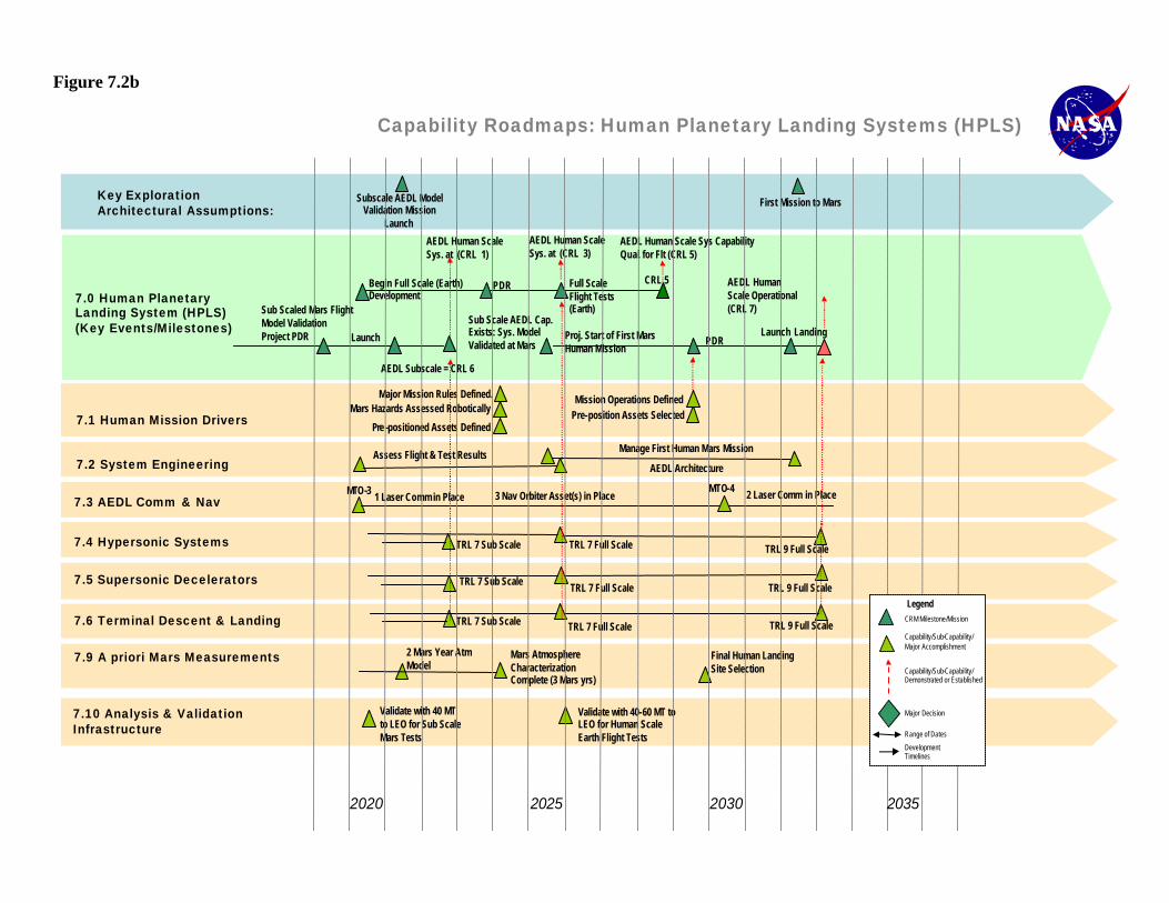
8/25/2005 Capability Roadmaps Report Page 153
Capability Roadmaps: Human Planetary Landing Systems (HPLS)
7.0 Human Planetary Landing System (HPLS) (Key Events/Milestones)
7.1 Human Mission Drivers
7.2 System Engineering
7.3 AEDL Comm & Nav
7.4 Hypersonic Systems
7.5 Supersonic Decelerators
7.6 Terminal Descent & Landing
7.9 A priori Mars Measurements
7.10 Analysis & Validation Infrastructure
MTO-3
Begin Full Scale (Earth) Development
Sub Scale AEDL Cap. Exists: Sys. Model Validated at Mars
Sub Scaled Mars Flight Model Validation Project PDR
PDR Full Scale Flight Tests (Earth)
Proj. Start of First Mars Human Mission
PDR
AEDL Human Scale Sys Capability Qual. for Flt (CRL 5)
Launch Landing
AEDL Human Scale Sys. at (CRL 1)
First Mission to Mars
AEDL Subscale = CRL 6
CRL 5 AEDL Human Scale Operational (CRL 7)
TRL 7 Sub Scale
2 Mars Year AtmModel
TRL 7 Sub Scale
TRL 7 Sub Scale
TRL 7 Full Scale
TRL 7 Full Scale
TRL 7 Full Scale
TRL 9 Full Scale
TRL 9 Full Scale
TRL 9 Full Scale
AEDL Human Scale Sys. at (CRL 3)
Validate with 40-60 MT to LEO for Human Scale Earth Flight Tests
Validate with 40 MT to LEO for Sub Scale Mars Tests
Major Mission Rules Defined.
Manage First Human Mars Mission
AEDL Architecture
Mars Hazards Assessed Robotically
Pre -positioned Assets Defined
Mission Operations Defined Pre-position Assets Selected
Mars Atmosphere Characterization Complete (3 Mars yrs)
3 Nav Orbiter Asset(s) in PlaceMTO-4
1 Laser Comm in Place 2 Laser Comm in Place
Final Human Landing Site Selection
Subscale AEDL Model Validation Mission
Launch
Launch
Assess Flight & Test Results
2020 2025 20352030
Key Exploration Architectural Assumptions:
Capability/Sub-Capability/Major Accomplishment
Capability/Sub-Capability/Demonstrated or Established
CRM Milestone/Mission
Major Decision
Range of Dates
Development Timelines
Legend
Figure 7.2b
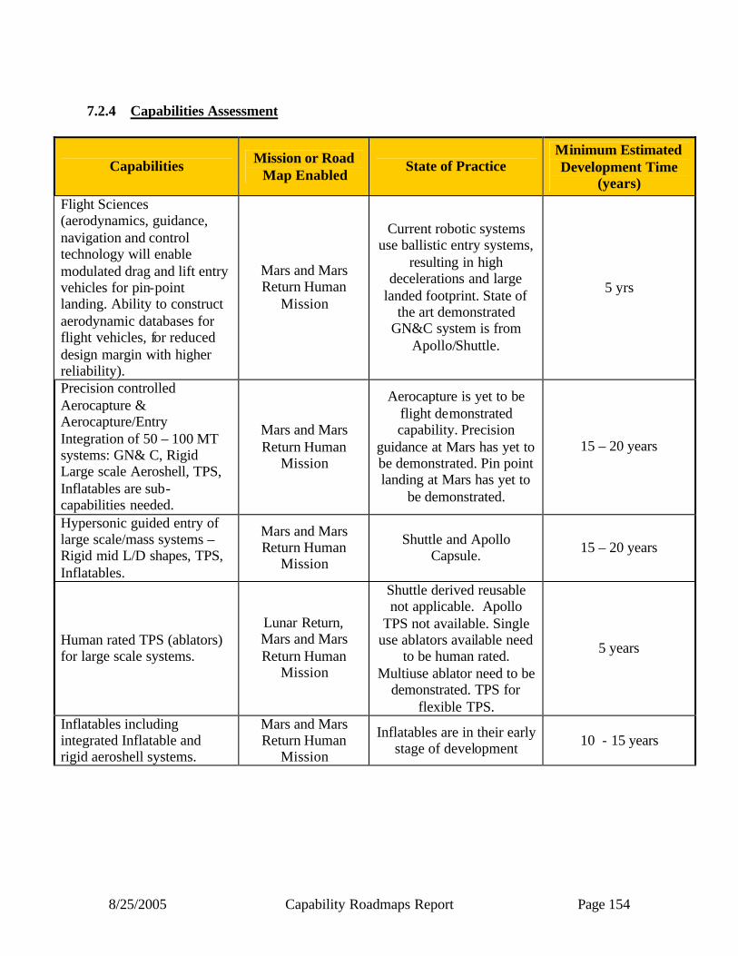
8/25/2005 Capability Roadmaps Report Page 154
7.2.4 Capabilities Assessment
Capabilities Mission or Road Map Enabled
State of Practice Minimum Estimated Development Time
(years) Flight Sciences (aerodynamics, guidance, navigation and control technology will enable modulated drag and lift entry vehicles for pin-point landing. Ability to construct aerodynamic databases for flight vehicles, for reduced design margin with higher reliability).
Mars and Mars Return Human
Mission
Current robotic systems use ballistic entry systems,
resulting in high decelerations and large
landed footprint. State of the art demonstrated
GN&C system is from Apollo/Shuttle.
5 yrs
Precision controlled Aerocapture & Aerocapture/Entry Integration of 50 – 100 MT systems: GN& C, Rigid Large scale Aeroshell, TPS, Inflatables are sub-capabilities needed.
Mars and Mars Return Human
Mission
Aerocapture is yet to be flight demonstrated capability. Precision
guidance at Mars has yet to be demonstrated. Pin point landing at Mars has yet to
be demonstrated.
15 – 20 years
Hypersonic guided entry of large scale/mass systems – Rigid mid L/D shapes, TPS, Inflatables.
Mars and Mars Return Human
Mission
Shuttle and Apollo Capsule. 15 – 20 years
Human rated TPS (ablators) for large scale systems.
Lunar Return, Mars and Mars Return Human
Mission
Shuttle derived reusable not applicable. Apollo
TPS not available. Single use ablators available need
to be human rated. Multiuse ablator need to be
demonstrated. TPS for flexible TPS.
5 years
Inflatables including integrated Inflatable and rigid aeroshell systems.
Mars and Mars Return Human
Mission
Inflatables are in their early stage of development 10 - 15 years
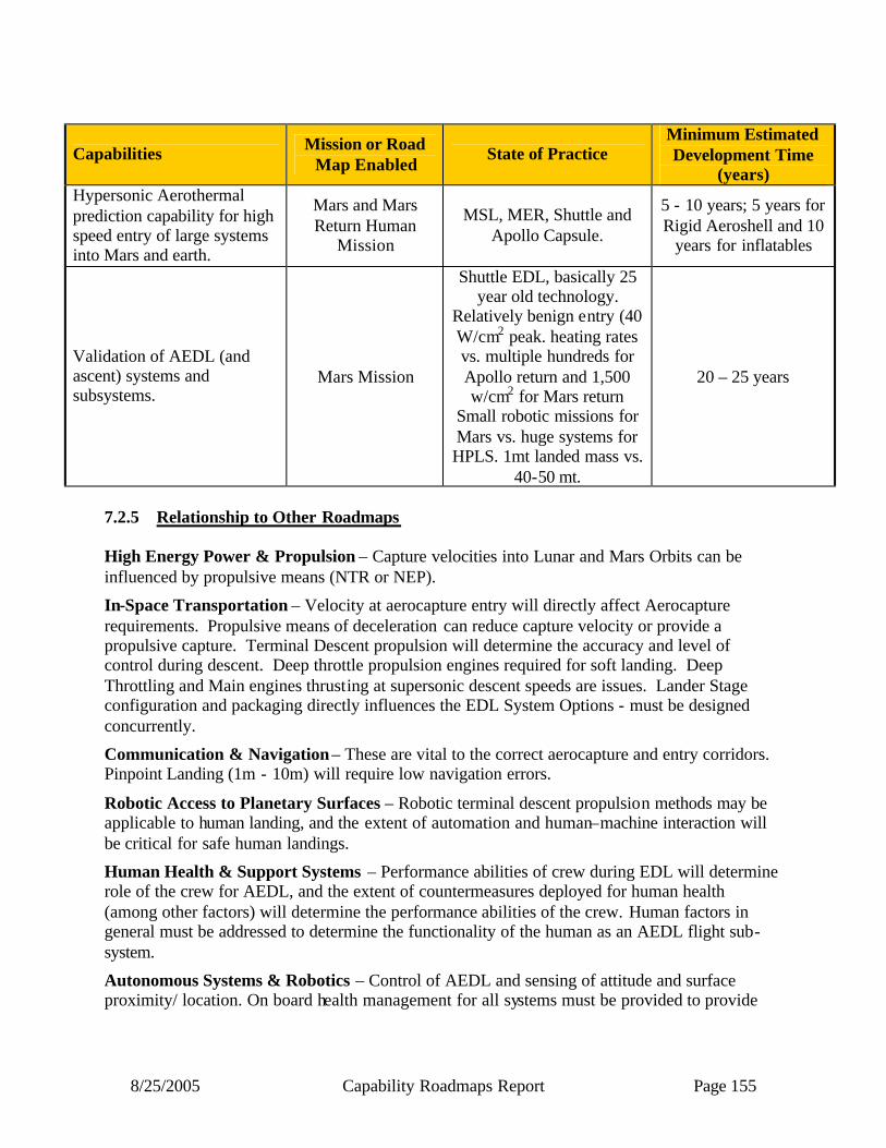
8/25/2005 Capability Roadmaps Report Page 155
Capabilities Mission or Road Map Enabled
State of Practice Minimum Estimated Development Time
(years) Hypersonic Aerothermal prediction capability for high speed entry of large systems into Mars and earth.
Mars and Mars Return Human
Mission
MSL, MER, Shuttle and Apollo Capsule.
5 - 10 years; 5 years for Rigid Aeroshell and 10
years for inflatables
Validation of AEDL (and ascent) systems and subsystems.
Mars Mission
Shuttle EDL, basically 25 year old technology.
Relatively benign entry (40 W/cm2 peak. heating rates vs. multiple hundreds for Apollo return and 1,500 w/cm2 for Mars return
Small robotic missions for Mars vs. huge systems for HPLS. 1mt landed mass vs.
40-50 mt.
20 – 25 years
7.2.5 Relationship to Other Roadmaps High Energy Power & Propulsion – Capture velocities into Lunar and Mars Orbits can be influenced by propulsive means (NTR or NEP).
In-Space Transportation – Velocity at aerocapture entry will directly affect Aerocapture requirements. Propulsive means of deceleration can reduce capture velocity or provide a propulsive capture. Terminal Descent propulsion will determine the accuracy and level of control during descent. Deep throttle propulsion engines required for soft landing. Deep Throttling and Main engines thrusting at supersonic descent speeds are issues. Lander Stage configuration and packaging directly influences the EDL System Options - must be designed concurrently.
Communication & Navigation – These are vital to the correct aerocapture and entry corridors. Pinpoint Landing (1m - 10m) will require low navigation errors.
Robotic Access to Planetary Surfaces – Robotic terminal descent propulsion methods may be applicable to human landing, and the extent of automation and human–machine interaction will be critical for safe human landings.
Human Health & Support Systems – Performance abilities of crew during EDL will determine role of the crew for AEDL, and the extent of countermeasures deployed for human health (among other factors) will determine the performance abilities of the crew. Human factors in general must be addressed to determine the functionality of the human as an AEDL flight sub-system.
Autonomous Systems & Robotics – Control of AEDL and sensing of attitude and surface proximity/ location. On board health management for all systems must be provided to provide

8/25/2005 Capability Roadmaps Report Page 156
fault tolerant EDL. Entry/Descent control software and landing algorithms must be efficient and robust.
Advanced Modeling Simulation & Analysis – Analysis modeling, simulation and trades of EDL Systems Architectures. Computational Fluid Dynamics & Finite Element Modeling will allow more cost efficient development,
Systems Engineering & Cost/Risk Analysis – Systems Engineering requirements are necessary to develop EDL systems. Cost, safety and especially risk will determine the method of EDL will be used in Architecture. Tools, process, and training for more effective estimation and development.
7.2.6 Infrastructure Assessment The competencies/expertise needed for Human Planetary Landing Systems include:
• Hypersonic entry systems with special focus on precision GN&C,
• Hypersonic/supersonic/hypersonic/terminal descent systems,
• Thermal protection materials,
• Aerosystems systems (rigid and flexible) and manufacturing of large scale systems,
• Fluid-structure interaction for the design and development of large scale inflatables,
• Capability for design and test of descent engines,
• System engineering/analysis capabilities to develop an integrated system,
• System engineering of ground, sub/full scale system validation,
• Human factors for human in the loop aspects of HPLS AEDL.
The capability workforce to develop system architecture and perform design/ analysis capability does not exist at one single entity and is spread across NASA, Industry and Academia. Design, development and verification of GN&C software capability exists mainly within the NASA centers, and is derived from the Apollo/ Shuttle expertise. The capability to develop advances thermal protection system is mainly within the NASA centers with limited capability with NASA contractors. The expertise to develop, test and design TPS systems is within a hand full of people across the NASA Centers and NASA Contractors. In addition NASA has strong human factors and space physiology expertise required for extended spaceflights.
A national human capital investment strategy that involves graduate students and on the job training of NASA and Industry personnel are needed to meet the challenges of the future.
The expertise to address the challenges of human Lunar and Mars exploration is derived from those that worked on the Apollo era. The training of the next generation of AEDL technologists with the requisite skills (see below) should begin immediately as an element of spooling up for the Lunar program
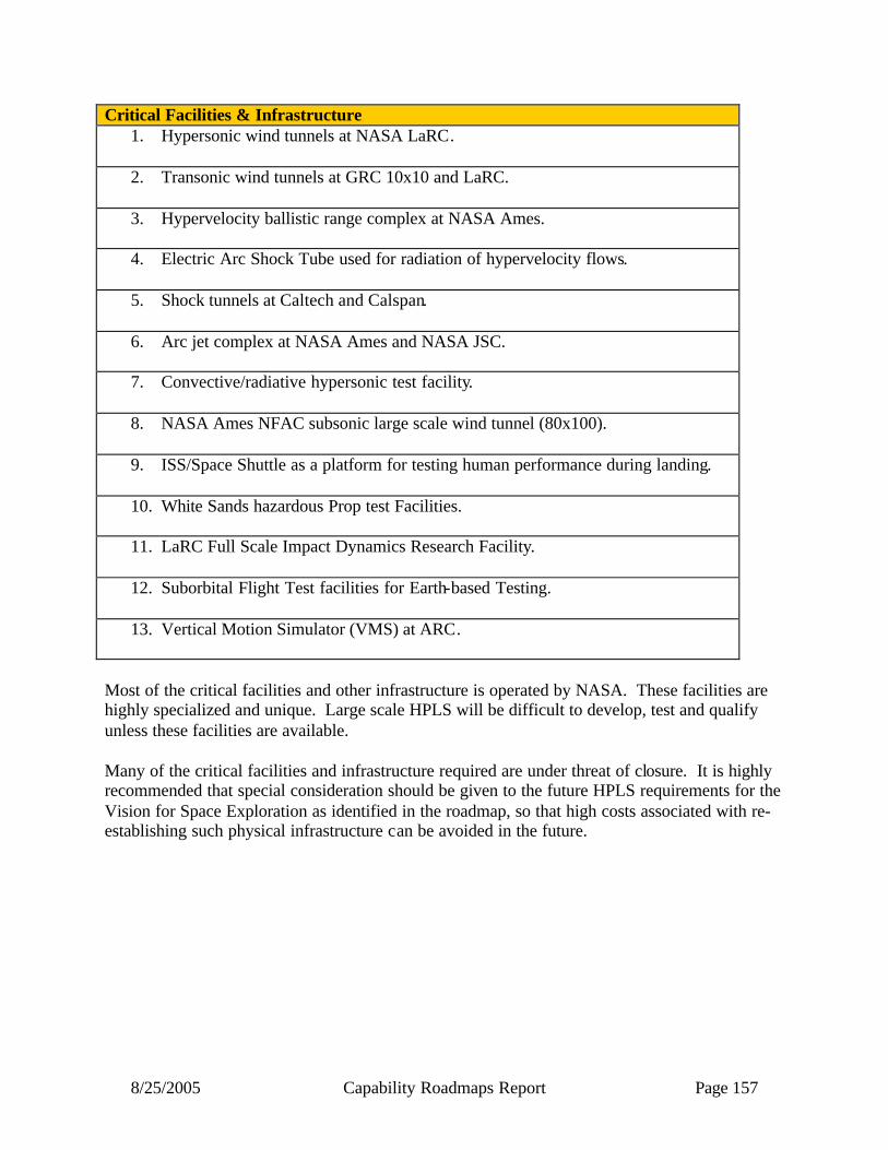
8/25/2005 Capability Roadmaps Report Page 157
Critical Facilities & Infrastructure 1. Hypersonic wind tunnels at NASA LaRC.
2. Transonic wind tunnels at GRC 10x10 and LaRC.
3. Hypervelocity ballistic range complex at NASA Ames.
4. Electric Arc Shock Tube used for radiation of hypervelocity flows.
5. Shock tunnels at Caltech and Calspan.
6. Arc jet complex at NASA Ames and NASA JSC.
7. Convective/radiative hypersonic test facility.
8. NASA Ames NFAC subsonic large scale wind tunnel (80x100).
9. ISS/Space Shuttle as a platform for testing human performance during landing.
10. White Sands hazardous Prop test Facilities.
11. LaRC Full Scale Impact Dynamics Research Facility.
12. Suborbital Flight Test facilities for Earth-based Testing.
13. Vertical Motion Simulator (VMS) at ARC.
Most of the critical facilities and other infrastructure is operated by NASA. These facilities are highly specialized and unique. Large scale HPLS will be difficult to develop, test and qualify unless these facilities are available.
Many of the critical facilities and infrastructure required are under threat of closure. It is highly recommended that special consideration should be given to the future HPLS requirements for the Vision for Space Exploration as identified in the roadmap, so that high costs associated with re-establishing such physical infrastructure can be avoided in the future.
8/25/2005 Capability Roadmaps Report Page 158
7.3 Summary We are a long way from understanding what the Mars AEDL system will look like. Significant near-term work is required to baseline a design for a Human Scale Mars AEDL system. If NASA waits until 2015 to initiate design and development of the Mars AEDL systems and scaled subsystems, it is unlikely that human Mars landings could be flown in the 2030’s.
Limited human physiological and psychological data on performance effects of long duration spaceflight and impacts of post-entry deceleration forces requires conservative assumptions for the design of the human-AEDL system. NASA should begin taking human performance measurements now before the Shuttle & ISS retires.
A near-total absence of measurements that validate the variation of the Mars atmosphere forces very conservative or prohibitive design requirements on the AEDL system to get human-rated reliability. NASA should initiate a program to acquire the data on the atmospheric variations so that these systems can be built. NASA should ensure that planned robotic EDL and surface assets have adequate atmosphere, aerothermal and aerodynamic instrumentation.
The US AEDL community and infrastructure is small and aging and therefore NASA needs to grow and invigorate this field to enable the HPLS capability. Despite its small numbers, the technical capabilities developed by the historic human and on-going robotic EDL community may be exploited to begin design and detailed assessment of human scale AEDL systems.
Overall, a robust and practical plan has been assembled by the HPLS team and with the proper implementation of such a plan, AEDL on Mars and the Moon (as well as successful return) by the crew to Earth will be enabled.
8/25/2005 Capability Roadmaps Report Page 159
Acronym list
AEDL – Aerocapture, Entry, Descent, and landing CBS - Capability Breakdown Structure CUBRC - Calspan - University of Buffalo Research Center DGB - Disk Gap Band (type of parachute) EDL - Entry, Descent, and Landing G or g - a force of one Earth gravity GN&C - Guidance, Navigation, and Cont rol GRC - Glenn Research Center IMU - Inertial Measurement Unit JPL - Jet Propulsion Laboratory JSC - Johnson Space Center krad - kilorads of radiation LENS - Large Energy National Shock tunnel LTA - Lighter Than Air LaRC - Langley Research Center LEO – Lower Earth Orbit MER - Mars Exploration Rover MFP - Mean Free Path MIL-SPEC - Military Specification (for component temperature ranges) MOLA – Mars Orbiting Laser Altimiter MPT - Mars Program Technology MSR - Mars Sample Return MT – Metric Ton NASA - National Aeronautics and Space Administration NEP – Nuclear-electric power NFAC - National Full-Scale Aerodynamics Facility NRC - National Research Council NSBF - National Science Balloon Facility NTR – Nuclear-thermal Reactor PP - Planetary Protection RAPS - Robotic Access to Planetary Surfaces RF - Radio Frequency RPS - Radioisotope Power Source SOTA - State Of The Art SRM - Strategic Roadmap TDT - Transonic Dynamics Tunnel TPS - Thermal Protection System TRL - Technology Readiness Level USSR – United Soviet Socialist Republics VMS – Vertical Motion Simulator VSR - Venus Sample Return VTOL - Vertical Take-Off and Landing WFF - Wallops Flight Facility We - Watts electric

8/25/2005 Capability Roadmaps Report Page 160
NASA
Capability Road Map (CRM) 8
Human Health and Support Systems Capability (HSS)
Executive Summary
Chair: Dennis J. Grounds, NASA JSC Co-Chair: Albert M. Boehm, Retired Industry
Coordinators
Directorate
Betsy Park NASA ESMD Gene Trinh, NASA ESMD Doug Craig, NASA ESMD
APIO
Jan Aikins, NASA ARC
Team Members
NASA
John Charles, NASA JSC Robin Carrasquillo, NASA MSFC
Gary Jahns, NASA JSC Glen Lutz, NASA JSC
Daniel Barta, NASA JSC Karri Knotts, NASA JSC Gary Jahns, NASA ARC
Administrative Support
Gina Miller, NASA JSC
Academia
Dave Akin University of Maryland Jeanne Becker, NSBRI
Robert Schlegel, University of Oklahoma
Industry
Bernard Harris, Retired. NASA
Robert Poisson, Hamilton Sundstrand
Al Witkowski, Pioneer Aerospace
8/25/2005 Capability Roadmaps Report Page 161
Capability Road Map (CRM) 8 further acknowledges the assistance and input from many colleagues. Life Support and Habitation Extra Vehicular Activity Daniel J. Barta JSC Robyn Carrasquillo MSFC A. Boehm Ham Sundstrand Jay Perry MSFC Frederick D. Smith JSC Karen D. Pickering JSC David Westheimer JSC John Fisher ARC Michele Perchonok NSBRI Raymond Wheeler KSC Darrell Jan JPL Gary A. Ruff GRC Julie Bassler MSFC Michelle Kamman , JSC D. Duncan Atchison, ARC Mark H. Kliss, ARC John.W.Hines, ARC Marc M. Cohen, ARC Gary W. Stutte, Dynamac Corp Neil C. Yorio, Dynamac Corp K. Wignarajah, E.A.S.I. Bimh S. Singh, GRC Brian J. Motil, GRC Mohammad. M. Hasan, GRC John. M. Sankovic, GRC Michael K. Ewert, JSC Donald L. Henninger, JSC Douglas J. Gruendel, KSC Guy J. Etheridge, KSC John C. Sager, KSC David R. Cox, KSC Melanie. P. Bodiford, MSFC Monica. S. Hammond, MSFC Ronald. J. King, MSFC John A. Hogan, Rutgers University, NSGF Julie A. Ray, Teledyne Brown Aaron L. Mills, Univ of Virginia Grace Cramp, JSC
Kerri Knotts, JSC Glenn Lutz, JSC Bob Poisson, HS Dave Akin, U of Md Mike Gernhardt, JSC Mike Rouen, JSC Gretchen Thomas, JSC Luis Trevino, JSC Joe Kosmo, JSC Sandra Wagner, JSC Amy Ross, JSC Robert Trevino, JSC Heather Paul, JSC Dave Foltz, GRC James Hieronymus. ARC Michelle Manzo, GRC Lara Kearney, JSC Jeff Patrick, JSC Diane Malarik, GRC Keith Todd, JSC S. Rajulu, JSC M. Whitmore, JSC
8/25/2005 Capability Roadmaps Report Page 162
8 Human Health and Support Systems Capability (Roadmap 8)
8.1 General Capability Overview 8.1.1 Capability Description The Human Health and Support Systems (HHSS) Capability Roadmap encompasses three of the seventeen areas of technologies to enable the Vision for Space Exploration identified in the “Report of the President’s Commission on Implementation of United States Space Exploration Policy,” June 2004: • Biomedical risk mitigation: Space medicine; remote monitoring, diagnosis and treatment. • Closed- loop life support and habitability: Recycling of oxygen, carbon dioxide, and water for
long-duration human presence in space. • Extravehicular activity systems: The spacesuit for the future, specifically for productive work
on planetary surfaces. This roadmap focuses on research and technology development and demonstration required to ensure the health, habitation, safety, and effectiveness of crews in and beyond low Earth orbit. It contains three distinct sub-capabilities: Human Health and Performance, Life Support and Habitation, and Extra-Vehicular Activity 8.1.2 Benefits The HHSS Roadmap defines the research and technologies required to enable life support, medical care, and extra-vehicular activity (EVA) capabilities for safe, sustained, and productive human exploration. The Human Health and Performance (HHP) area guides the research and countermeasure development to reduce the risks to humans in space flight, as well as define the technology necessary for maintenance of the daily functiona l requirements of the human system. It includes: Space Radiation, Medical Care, Human Physiological Countermeasures, Behavioral Health and Performance, and Space Human Factors. These capabilities protect and enhance human health and performance, increasing the potential for human exploration mission success. Life Support and Habitation (LSH) focuses on the research and technology development to sustain the life of the flight crew during transit and planetary phases of exploration. It includes: Life Support Systems (air, thermal, water, waste, food), Environmental Monitoring and Control, Contingency Response Technologies, and Exploration Habitats. Closed- loop air, water and food systems will greatly reduce logistics for the Environmental Control and Life Support System (ECLSS), making Human Exploration missions more feasible and sustainable. Extra-Vehicular Activity (EVA) program develops the technology required to sustain the life of humans outside of the life support systems of the vehicle and surface habitats, as well as the tools required to perform exploration and contingency EVA. It includes: EVA Suit, Pressurized

8/25/2005 Capability Roadmaps Report Page 163
Volumes, EVA Tools, and Ground Support Equipment. EVA is certain to be required in human exploration missions, making this capability a necessity to achieve mission objectives.
8.1.3 Key Architecture / Strategic Decisions
Key Architecture/Strategic Decisions
Date Decision is Needed
Impact of Decision on Capability
Exploration health standards (level of care, operating bands) definitions
2006 Determines countermeasure development and medical care technology selection
ISS availability for flight evaluation & validation of capabilities for exploration missions, including up and down access.
2005 ISS is essential for validating biomedical countermeasures for Mars-duration missions. ISS is the ideal platform for testing medical and life support systems capabilities
The extent to which the Moon can be used as a test bed for Mars
2008 The Moon is a good candidate flight analog for hypo-gravity countermeasure and technology validation for Mars missions
Planning dates (not ranges) for moon and Mars
2006 Affects dates for capability development completion
In-space construction: human EVA requirements, human/robot task allocation
2006 Affects type and robustness of suits and tools, development of teleoperation system
Will artificial gravity be used for the Mars Transit Vehicle?
2016 Affects countermeasure development, technology selection and development
Vehicle atmospheric pressure and composition
2006 Affects many life support systems
Length of missions 2006 Affects crew selection, closed loop life support requirements
Mission planning: what is the crew expected to do on the planetary surface?
Ongoing Affects operational planning for transit vehicle to ensure crew capabilities, surface EVA suit development
Resource allocation from spacecraft systems
2008 Brackets trade space for physio-chemical and biological life support technologies; affects consumables; power is enabling for bioregenerative systems for food production
Availability and integration of ISRU into spacecraft systems
2008 Impacts EVA operations, habitat structural requirements, ECLSS consumables and technologies
Crew size and composition 2008 Determine scope of overall requirements for habitats

8/25/2005 Capability Roadmaps Report Page 164
8.1.4 Major Technical Challenges The technical challenges for Human Health and Support Systems capability development are unique, especially in the area of Human Health and Performance. In many cases, the development will result in requirements as opposed to a piece of equipment. Without the research and test beds to develop these requirements, crew health and performance cannot adequately be supported on long duration exploration missions. Table 8.1 represents the top 14 major challenges across Human Health and Support Systems, and includes technical development as well as requirements development.
2006-2010 Optimize habitat pressure/suit pressure across exploration architecture.
Determine advanced EVA system design requirements and perform architectural trade studies to meet CEV and overall exploration requirements (Moon and Mars). Enable effective crew health maintenance for long duration microgravity missions by risk-reduction data collection and countermeasure development onboard the ISS and Shuttle. Translate agency medical requirements and standards into mission-specific medical care systems, and design system within resource allocations. Develop space human factors requirements, guidelines and design tools to increase the likelihood of mission success by improving human-system interactions and human-system interface designs throughout exploration missions. Develop behavioral health and performance requirements, standards, and models to increase the likelihood of mission success by reducing human error related to reduced performance readiness, behavioral health dysfunction, and team member incompatibility. Develop behavioral health and performance requirements, standards, and models to increase the likelihood of mission success by reducing human error related to reduced performance readiness, behavioral health dysfunction, and team member incompatibility. Provide for thermal control and heat rejection for EVA, habitats, and life support systems across the full lunar day and night.
2010 – 2020 Reduce the uncertainty associated with health effects of space radiation exposure. Since NASA needs to plan for the worst case, a large uncertainty (currently a factor of 4 to 6) probably unnecessarily constrains future human flights. Improved radiation shielding by a factor of 2 without increasing added mass. See Figure 8.1.
Architecture/Strategy
Key Architecture/Strategic Decisions
Date Decision is Needed
Impact of Decision on Capability
Mission location (Moon) 2006 Determines space craft and suit thermal requirements and methods for heat rejection, accessibility to ISRU, and zones of minimal biological risk for planetary protection
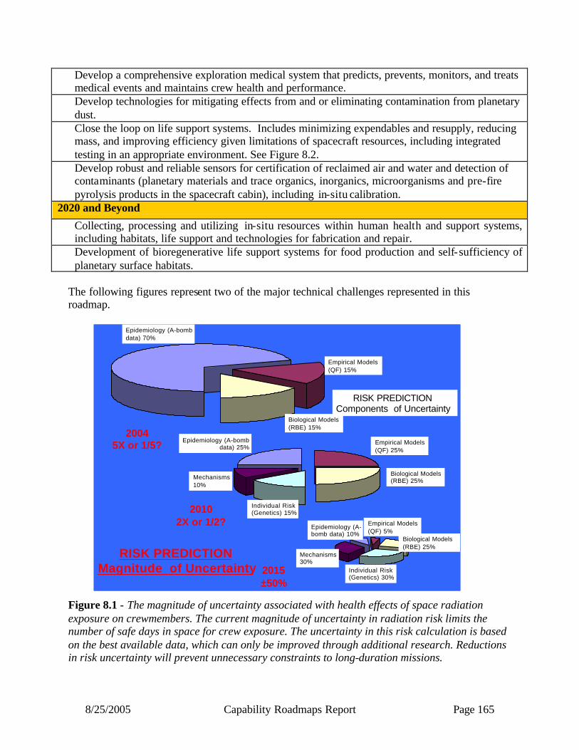
8/25/2005 Capability Roadmaps Report Page 165
Develop a comprehensive exploration medical system that predicts, prevents, monitors, and treats medical events and maintains crew health and performance. Develop technologies for mitigating effects from and or eliminating contamination from planetary dust. Close the loop on life support systems. Includes minimizing expendables and resupply, reducing mass, and improving efficiency given limitations of spacecraft resources, including integrated testing in an appropriate environment. See Figure 8.2. Develop robust and reliable sensors for certification of reclaimed air and water and detection of contaminants (planetary materials and trace organics, inorganics, microorganisms and pre-fire pyrolysis products in the spacecraft cabin), including in-situ calibration.
2020 and Beyond
Collecting, processing and utilizing in-situ resources within human health and support systems, including habitats, life support and technologies for fabrication and repair. Development of bioregenerative life support systems for food production and self-sufficiency of planetary surface habitats.
The following figures represent two of the major technical challenges represented in this roadmap. Figure 8.1 - The magnitude of uncertainty associated with health effects of space radiation exposure on crewmembers. The current magnitude of uncertainty in radiation risk limits the number of safe days in space for crew exposure. The uncertainty in this risk calculation is based on the best available data, which can only be improved through additional research. Reductions in risk uncertainty will prevent unnecessary constraints to long-duration missions.
Epidemiology (A-bomb data) 70%
Empirical Models (QF) 15%
Biological Models (RBE) 15%
Mechanisms10%
Individual Risk(Genetics) 15%
Epidemiology (A-bomb data) 25%
Epidemiology (A-bomb data) 10%
Empirical Models (QF) 25%
Empirical Models (QF) 5%
Biological Models(RBE) 25%
Mechanisms30%
Individual Risk(Genetics) 30%
RISK PREDICTIONComponents of Uncertainty
20045X or 1/5?
20102X or 1/2?
2015±50%
RISK PREDICTIONMagnitude of Uncertainty
Biological Models (RBE) 25%
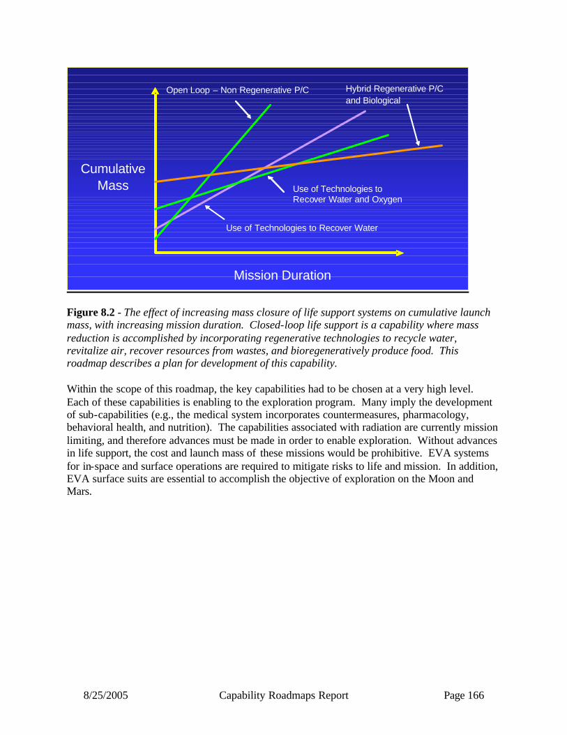
8/25/2005 Capability Roadmaps Report Page 166
Figure 8.2 - The effect of increasing mass closure of life support systems on cumulative launch mass, with increasing mission duration. Closed-loop life support is a capability where mass reduction is accomplished by incorporating regenerative technologies to recycle water, revitalize air, recover resources from wastes, and bioregeneratively produce food. This roadmap describes a plan for development of this capability. Within the scope of this roadmap, the key capabilities had to be chosen at a very high level. Each of these capabilities is enabling to the exploration program. Many imply the development of sub-capabilities (e.g., the medical system incorporates countermeasures, pharmacology, behavioral health, and nutrition). The capabilities associated with radiation are currently mission limiting, and therefore advances must be made in order to enable exploration. Without advances in life support, the cost and launch mass of these missions would be prohibitive. EVA systems for in-space and surface operations are required to mitigate risks to life and mission. In addition, EVA surface suits are essential to accomplish the objective of exploration on the Moon and Mars.
Cumulative Mass
Mission Duration
Open Loop – Non Regenerative P/C Hybrid Regenerative P/C and Biological
Use of Technologies to Recover Water and Oxygen
Use of Technologies to Recover Water
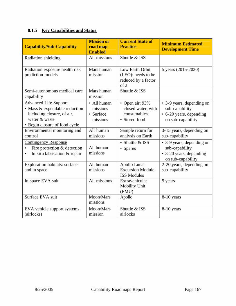
8/25/2005 Capability Roadmaps Report Page 167
8.1.5 Key Capabilities and Status
Capability/Sub-Capability Mission or road map Enabled
Current State of Practice
Minimum Estimated Development Time
Radiation shielding
All missions
Shuttle & ISS
Radiation exposure health risk prediction models
Mars human mission
Low Earth Orbit (LEO): needs to be reduced by a factor of 2
5 years (2015-2020)
Semi-autonomous medical care capability
Mars human mission
Shuttle & ISS
Advanced Life Support • Mass & expendable reduction
including closure, of air, water & waste
• Begin closure of food cycle
• All human missions
• Surface missions
• Open air; 93% closed water, with consumables
• Stored food
• 3-9 years, depending on sub-capability
• 6-20 years, depending on sub-capability
Environmental monitoring and control
All human missions
Sample return for analysis on Earth
3-15 years, depending on sub-capability
Contingency Response • Fire protection & detection • In-situ fabrication & repair
All human missions
• Shuttle & ISS • Spares
• 3-9 years, depending on sub-capability
• 3-20 years, depending on sub-capability
Exploration habitats: surface and in space
All human missions
Apollo Lunar Excursion Module, ISS Modules
2-20 years, depending on sub-capability
In-space EVA suit All missions Extravehicular Mobility Unit (EMU)
5 years
Surface EVA suit
Moon/Mars missions
Apollo 8-10 years
EVA vehicle support systems (airlocks)
Moon/Mars mission
Shuttle & ISS airlocks
8-10 years
8/25/2005 Capability Roadmaps Report Page 168
8.2 Roadmap Development 8.2.1 Legacy Activities and Roadmap Assumptions Technology assessments performed by the Capability Requirements, Analysis, and Integration (CRAI) Team, sponsored by the former office of NASA’s Space Architect, included much of the content of the Human Health and Support Systems Capability Roadmap. In FY03, enabling capabilities recognized by CRAI included “Closed-Loop Life Support and Habitability”, “Extravehicular Activity Systems” and “Biomedical Risk Mitigation”. These capabilities were recommended for further study by the Aldridge Commission. In FY04, CRAI block 2.3, “Human Support Systems,” included twelve capabilities: Atmospheric Management, Advanced Water Recovery Systems, Waste Management, Crop Systems, Human Factors, Advanced Thermal Control Systems, Human Support Systems, Advanced Environmental Monitoring and Control, Advanced Food Technology, Human Health Counter Measures, Behavioral Health and Performance, and Autonomous Health Care. CRAI block 2.8, “Crew Mobility (EVA Systems),” included four capabilities: Portable Life Support System, System Integration, Crew Surface Mobility, and Airlocks. These efforts resulted in a series of white papers, capability and technology data sheets (including figures of merit), and simplified roadmaps. The Bioastronautics Roadmap was developed to identify and assess risks for human space exploration missions, prioritize research and technology and communicate those priorities, guide solicitation, selection, and development of NASA research and technology, assess progress towards reduction and management of risks, and deliver the appropriate products and knowledge. The roadmap describes 45 risks integrated over 16 disciplines contained in five cross-cutting areas: Human Health and Countermeasures, Autonomous Medical Care, Behavioral Health and Performance, Radiation Health and Advanced Human Support Technologies. For more information, go to http://bioastroroadmap.nasa.gov/index.jsp. 8.2.2 Top Level Architectural Assumptions & Applications Ethics The following Design Reference Missions were used as guidance in some instances: • Human Exploration of Mars: Artificial-Gravity Nuclear Electric Propulsion Option • Reference Mission Version 3.0 Addendum to the Human Exploration of Mars • Mars 98 Reference mission: Reference Mission of the NASA Mars Exploration Study Team • Lunar Surface Reference Missions: A Description of Human and Robotic Surface Activities • The Mars Surface Reference Mission: A Description of Human and Robotic Surface
Activities The study, “Interviews with the Apollo Lunar Surface Astronauts in Support of Planning for EVA System Design,” NASA Tech Memo 108846, was used in the EVA section. Advanced Life Support utilized documents prepared by its Systems Integration, Modeling and Analysis technical element, including the “Baseline Values and Assumptions Document,” NASA Contractor Report Series CR-2089 and the “Advanced Life Support Reference Missions Document,” JSC Document JSC-39502A. http://advlifesupport.jsc.nasa.gov

8/25/2005 Capability Roadmaps Report Page 169
Potential mission timeframes follow the Document: “ESMD-RQ-0019 Preliminary Title: CEV Concept of Operations Effective Date: 1 September 2004.” “Initial Capability Roadmap Requirements Framework,” Advanced Planning and Integration Office framework released to Roadmap Teams on November 24, 2004. 8.2.3 Capability Breakdown Structure The Capability Breakdown Structure (CBS) used in this document does not reflect Agency Work Breakdown Structures in place at the writing of this document. The following roadmaps were recommended in the “Report of the President’s Commission on Implementation of United States Space Exploration Policy, “ June 2004: • Biomedical risk mitigation: Space medicine; remote monitoring, diagnosis and treatment. • Closed- loop life support and habitability: Recycling of oxygen, carbon dioxide, and water for
long-duration human presence in space. • Extravehicular activity systems: The spacesuit for the future, specifically for productive work
on planetary surfaces. The initial direction from the Advanced Planning and Integration Office included these categories in the HHSS Roadmap: • Closed- loop life support and consumables • Biomedical monitoring, radiation/hazard detection • Risk mitigation, medical techniques • Spacesuits, EVA systems, exploration habitats The HHSS roadmap created three distinct sub-capabilities to encompass all of these: • Human Health and Performance • Life Support and Habitation • Extra-Vehicular Activity

8/25/2005 Capability Roadmaps Report Page 170
Capability Breakdown Structure
Human Health& Support Systems
Lead: Dennis Grounds/ NASA
Chair: Dennis Grounds/NASACo-Chair: Al Boehm Hamilton Sundstrand (Ret.)
Lead: Dan Barta/ NASA Lead: Kerri Knotts/ NASA
Human Health & Performance
8.1
8.2.1
8.2.2
8.2.3
8.2
8.2.4
8.2.5
Space Radiation
8.1.1
8.1.2
8.1.3
8.1.4
8.3.1
8.3.2
8.3
8.3.3
8.3.4
Life Support & Habitation
Extra-Vehicular Activity
Medical Care
Human Physiological
Countermeasures
Behavioral Health &
Performance
Suits
EVA Tools & Mobility Aids
Airlocks/ Pressurized
Volumes
Ground Support Systems
Air Revitalization
Water Reclamation
Thermal Control
Solid Waste Management
Food Provisioning & Management
8.1.5
Space Human Factors
8.2.6
8.2.7
8.2.8
8.2.9
8.2.10
Biomass Production
Environmental Monitoring &
Control
Fire Prevention, Detection,
Suppression
In Situ Fabrication &
Repair
Exploration Habitats
8.0
Figure 8.3
8/25/2005 Capability Roadmaps Report Page 171
• 8.2.4 Roadmap Logic The Human Health and Performance (8.1) section of the roadmap (Figures 8.3a and 8.3b) is in large part guided by medical standards to mitigate the physiological conditions imposed upon the human system by space flight in these areas: radiation exposure, bone and muscle loss, cardiovascular fitness decline, sensory motor changes, behavioral and performance changes, immunology effects, and nutrition deficits. The five sub-capabilities address these standards. Space Radiation (8.1.1) includes shielding, monitoring, exposure limits, and potential biomedical countermeasures. Shielding and monitoring requirements are provided in an iterative process to each vehicle/habitat design. Exposure limits per mission and per lifetime are established for crewmembers based on modeling techniques. For Mars missions, data from robotic precursor missions is required to validate current models. Biomedical countermeasures most probably will not be available until the Mars missions. Medical Care (8.1.2) will deliver a medical system for each vehicle, each habitat, and each mission. The content of those systems will be based on medical standards and mission architecture. The systems will greatly increase autonomy and will incorporate an improved understanding of pharmacology and nutrition. Human Health Countermeasures (8.1.3) includes exercise equipment and prescriptions as well as physiological countermeasures for bone and muscle loss, cardiovascular fitness decline, sensory motor changes, immunology effects, and environmental physiology (e.g., decompression sickness, toxicity, microbiology). These sub-capabilities will be delivered internally to medical care for implementation. Artificial gravity is also included in this area. The research in this area will be used to prepare a decision package for the Mars transit vehicle. Behavioral Health and Performance (8.1.4) addresses team cohesion and productivity, psychological health management, performance readiness evaluation, and individual/ crew selection. Examples of technology deliverables are predictive models for fatigue, sensors and tests for stress monitoring and cognitive readiness to perform, and tools for family/ground support. A major deliverable, for Mars missions especially, is validated selection and training requirement for crewmembers. Space Human Factors (8.1.5) uses modeling and simulation, design tools, performance measurements, and training and decision support systems to maximize human performance capability. Human-centric vehicle and habitat designs will enhance human performance capabilities and increase the likelihood of mission success. Space Human Factors encompasses development of human-robotic interfaces and teleoperation capability. The Life Support and Habitation section (8.2) of the HHSS Capability Roadmap (Figures 8.4a and 8.4b) comprises development of capabilities associated with the pressurized cabin of spacecraft and planetary surface habitats. This includes development of capabilities for: a)

8/25/2005 Capability Roadmaps Report Page 172
advanced life support, including air revitalization, thermal control, water recovery, solid waste management, food provisioning and management, and production of food through biomass production; b) environmental monitoring and control; c) contingency response, including fire protection, detection and suppression and in-situ fabrication and repair; and d) exploration habitats. The specific milestones address capability gaps and improvements in efficiency to reduce consumables including mass, power, volume, and crew time. The roadmap describes risk mitigation and technology development to achieve targets of TRL 6, consistent with timelines for missions addressed by the Vision for Space Exploration. Key facilities necessary to execute the roadmap include ground-based test beds, analog sites, and reduced gravity test facilities (ground and flight). Test facilities will allow for integrated evaluations of candidate technologies with realistic process streams that provide relevant environments for technology maturation through TRL 6. Ground-based test beds capable of full-scale, high-fidelity, mission- level (full mission integration), and long-duration operation do not currently exist. A thorough understanding of the gravitational dependence of life support and habitation processes is critical to enable the design of these technologies, particularly when systems involve multiphase systems (gas- liquid, gas-solid, and solid- liquid phases) and phase changes (boiling and condensation). Access to the ISS will be critical to provide a long duration microgravity environment for technology validation. Ground-based facilities, including NASA's low-gravity aircraft, drop towers, and similar facilities will also be of critical importance. Air Revitalization (8.2.1): Technology development for atmosphere revitalization (AR) includes two primary focus areas—cabin atmospheric quality control, and gas supply and ventilation. Cabin atmospheric quality control has three developmental paths: open- loop regenerative, closed- loop regenerative, and loop closure technologies. Open- loop regenerative products are directed at early transit vehicles, with derivatives for landers, surface habitats, and rovers for short- and long-duration stays. In parallel, closed- loop regenerative systems and loop closure technologies are developed. An initial closed- loop regenerative system is developed for validation on a long duration lunar mission. Improvements are made in both open- and closed-loop systems to enable exploration of Mars later in the development program. Air revitalization has significant interfaces with other systems, including water, thermal, waste management, etc. Water Recovery (8.2.2): Water recovery systems transform crew and system wastewater into potable water for crew and system reuse. Achieving closure of water systems with minimal requirements for re-supply require sub-capabilities with these six basic functions: 1) collection and storage of wastewater; 2) primary processing (organic and nitrogenous contaminant reduction); 3) secondary processing (inorganic contaminant reduction); 4) brine dewatering; 5) post-processing and disinfection (polishing treated water to meet potability standards) and 6) storage and transport of potable water prior to consumption. Wastewater volume and quality varies with mission duration and habitat maturity. The optimal system for water recovery will change over the duration of the exploration timeline. It includes biological and physicochemical processes, ISRU, and is integrated with other life support capabilities that generate or utilize water.
8/25/2005 Capability Roadmaps Report Page 173
Thermal Control (8.2.3): Active Thermal Control System (ATCS) hardware addresses basic functions of heat acquisition, heat transport, and heat rejection. Heat acquisition hardware includes technologies to control cabin air temperature and collect humidity condensate, coldplates with decreased mass, and liquid-to- liquid heat exchangers that have two physical barriers preventing interpath leakage. Condensate collection on long-duration missions is of concern due to the potential for fouling. Heat transfer includes the selection of safe working fluids for the ATCS and heat pumps for the hot environments associated with lunar missions and two-phase designs for missions with high heat loads transported over long distances. Heat rejection includes improvements to evaporative heat-rejection devices for use on short-duration transport vehicles and landers, and development of advanced dust-resistant radiators. Solid Waste Management (8.2.4): Capability development includes advanced technologies for volume reduction, water removal, safening-stabilization, containment and disposal, and resource recovery. The development of waste management technologies is strongly driven by mission length, requirements for crew health, safety, and quality of life, and requirements for planetary protection. Early development and testing of alternatives for each technology will be followed by down selection, further development of the selected approaches, microgravity evaluation and testing, integrated system testing with other life support subsystems, and testing in relevant environments. Food Provisioning & Management (8.2.5): Food systems for future exploration missions will provide the crew with safe, nutritious, and acceptable food, minimize the use of resources, and provide for crew health and well being. For initial missions including transit, the approach includes development of a stored ready-to-eat food system with a 3-5 year shelf life using advanced preservation methods, packaging materials and environmentally suitable stowage conditions. During later missions, including planetary surfaces, a food system using bulk stored or harvested raw commodities processed into edible ingredients will be developed. Whether using a stored processed, or combination food system, appropriate menus and recipes will be developed that incorporate processed ingredients and/or freshly grown fruits and vegetables. Biomass Production (8.2.6): Two major products are targeted: 1) a small (0.25 to 1 m2 growing area) vegetable production unit for transit vehicles to supplement a stored food system with fresh foods, and 2) a larger (10 m2 or more growing area) crop production unit for planetary surfaces, to provide 10% of the food requirement and contribute to air revitalization and water recycling. Technology validation on ISS and the lunar surface will support prototype development and “relevant environment” testing for Mars transit and surface missions, respectively. Environmental Monitoring and Control (8.2.7): The closed spacecraft environment requires careful monitoring for gradual buildup of harmful trace chemicals and microorganisms. Hazardous events must be detected rapidly and may be minimized by early detection of indicators. Exploration missions cannot employ the current practice of returning air and water samples to earth for chemical and microbial analysis, and will therefore require on-board monitoring and certification of recycled consumables.
8/25/2005 Capability Roadmaps Report Page 174
Earlier, shorter missions have air monitoring of chemical constituents as the most immediate priority. As mission length increases, monitoring of water, and monitoring microbial targets become important. Missions to planetary surfaces will require monitoring of those surface environments for human hazards. Efficient application of integrated control requires that it be developed as monitoring and life support are developed, in stages, as a delayed short future thrust would carry high risk of failure. Fire Prevention, Detection, Suppression (8.2.8): Four sub-capabilities include: 1) fire prevention and material flammability research and develop updated requirements for flammability and materials selection based on reduced gravity flammability data; 2) fire detection: development of new detectors sensitive to both pre-fire and fire signatures, and resistant to nuisance false alarms from dust; 3) fire suppression and response: more effective, safer suppressants to reduce amount discharged, to mitigate post- fire toxic by-products and collateral damage; minimize impact to crew, system, and mission; and 4) Fire Scenarios and Training - increased efficiency of fire response through simulation of realistic fire scenarios and crew training. Technology development and verification is dependent on extended duration low-g tests on ISS. In-Situ Fabrication and Repair (8.2.9): Future long duration missions away from Earth may be able to recover from equipment failure if the capability to repair or fabricate spare parts is present. The Fabrication portion of this roadmap addresses the technology development of multi-material fabricators that initially use an Earth-supplied stock of metals, plastics, composites and electronic parts. In addition, the technology needs to be miniaturized and "ruggedized" to allow operations in micro- and hypo-gravity environments, with the eventual goal of using in-situ resources as feedstock. The repair portion of this roadmap addresses development of adhesive/amalgams for use on the lunar and Martian surfaces, and development of an electronics repair capability. Exploration Habitats (8.2.10): The development process for exploration habitats is equivalent to that of integrated vehicle design and development. Initial mission-specific operational requirements will drive concepts for the basic structure and functionality. It is expected that various styles of habitats will be necessary to support the variety of missions of the exploration program, and may include pre- integrated, deployable and/or in-situ resource utilization. All habitats, surface or transit, will utilize technologies common with those of other vehicles or systems, and will require a systems engineering approach. On the basis of the current Exploration Concept of Operations (Con Ops) and Crew Exploration Vehicle (CEV) Level I Requirements, the following Extra-Vehicular Activity (8.3) capabilities are needed: contingency EVA capability for CEV, crew survivability capability and protection from vehicle depressurization, and surface exploration capability. The EVA section of the roadmap (Figures 8.4a and 8.4b) breaks these capabilities out in the following manner: The EVA suits (8.3.1) will support launch and entry capability, in-space contingency EVA capability and surface exploration. These highly integrated suits will allow autonomous human operation outside the pressurized environment and contain the following critical sub-capabilities:

8/25/2005 Capability Roadmaps Report Page 175
• Livable Pressure Containment (Pressure Garment) • Breathable Atmosphere (Ventilation System), including primary and emergency oxygen
systems; CO2, trace gas and humidity removal; pressure regulation; ventilation flow, as well as, monitoring, sensing, command and control and caution and warning functions
• Thermal Control: heat acquisition, heat transfer and heat rejection • Power: power generation, power storage and power transfer • Communications and Informatics • Environmental Protection (protect suit from the environment) • Cross-cutting System Adaptability (Vehicle Interface: CEV, Lunar Surface Ascent Module,
Habitats, Airlocks, Rovers) • Self Rescue Ancillary EVA tools and mobility aids (8.3.2) include items that attach to a space suit, such as lighting and cameras, sensors, task-specific devices and safety gear. EVA tools, such as power and hand tools, provide the capability for a space suited human to conduct exploration and on-orbit operations. In a micro-gravity environment, EVA translation aids will be required to enable an EVA crewmember to translate, react to forces and loads, and restrain themselves in order to do useful work. Surface exploration will require a new complement of tools for sample acquisition, archiving, and handling. Surface infrastructure (habitats, rovers, robotic assistants) will require maintenance and servicing, which will in turn necessitate handling of substantial objects in a gravitational field. This new cadre of tools will be determined as surface exploration requirements are further defined. Airlocks/Pressurized Volumes (8.3.3) provide separable constrained volumes to deal with dust mitigation and other contamination issues from planetary surfaces, and must be designed to minimize leakage and exchange of gases. Dust contamination will be a significant issue on the surface of both the Moon and Mars. Dust mitigation and control must be considered in the design of planetary vehicles and EVA suit systems so that dust particles are not brought into the breathing volume. Along with dust-repelling suit technology advancements, habitat and vehicle design play a key role in preventing dust from entering the habitable volume. Other pressurized systems (atmospheric assembly and maintenance systems, pressurized rovers, mobile habitats) are at early TRL levels and need focused development support. The EVA Ground Support System (8.3.4) includes the necessary facilities and associated infrastructure to support EVA-related testing, technology development and flight program simulations as well as EVA system ground processing. These include component and integrated system test facilities; ground facilities for processing training and flight hardware; and analogs and trainers for planetary environments for testing suit components, subsystem and integrated systems in relevant environments, proving operational concepts and conducting training (dust, radiation, micrometeorite, biochemical, pressure, terrain, vacuum, low-gravity, virtual reality). Many of these facilities currently exist, but will require substantial upgrades for use with the new EVA system, and additional facilities need to be developed. 8.2.5 Capabilities Assessment
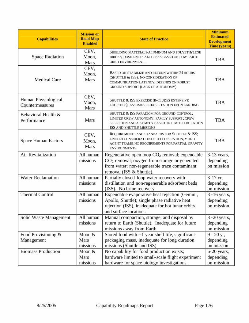
8/25/2005 Capability Roadmaps Report Page 176
Capabilities Mission or Road Map
Enabled State of Practice
Minimum Estimated
Development Time (years)
Space Radiation CEV, Moon, Mars
SHIELDING MATERIALS-ALUMINUM AND POLYETHYLENE BRICKS; DOSE LIMITS AND RISKS BASED ON LOW EARTH ORBIT ENVIRONMENT .
TBA
Medical Care
CEV, Moon, Mars
BASED ON STABILIZE AND RETURN WITHIN 24 HOURS (SHUTTLE & ISS); NO CONSIDERATION OF COMMUNICATION LATENCY; DEPENDS ON ROBUST GROUND SUPPORT (LACK OF AUTONOMY)
TBA
Human Physiological Countermeasures
CEV, Moon, Mars
SHUTTLE & ISS EXERCISE (INCLUDES EXTENSIVE LOGISTICS); ASSUMES REHABILITATION UPON LANDING TBA
Behavioral Health & Performance
Mars
SHUTTLE & ISS PARADIGM FOR GROUND CONTROL; LIMITED CREW AUTONOMY; FAMILY SUPPORT ; CREW SELECTION AND ASSEMBLY BASED ON LIMITED DURATION ISS AND SHUTTLE MISSIONS
TBA
Space Human Factors CEV, Moon, Mars
REQUIREMENTS AND STANDARDS FOR SHUTTLE & ISS; LIMITED CONSIDERATION OF TELEOPERATION, MULTI-AGENT TEAMS, NO REQUIREMENTS FOR PARTIAL GRAVITY ENVIRONMENTS
TBA
Air Revitalization All human missions
Regenerative open loop CO2 removal; expendable CO2 removal; oxygen from storage or generated from water; non-regenerable trace contaminant removal (ISS & Shuttle).
3-13 years, depending on mission
Water Reclamation All human missions
Partially closed- loop water recovery with distillation and non-regenerable adsorbent beds (ISS). No brine recovery
3-17 yr, depending on mission
Thermal Control All human missions
Expendable evaporative heat rejection (Gemini, Apollo, Shuttle); single phase radiative heat rejection (ISS), inadequate for hot lunar orbits and surface locations
3 -16 years, depending on mission
Solid Waste Management All human missions
Manual compaction, storage, and disposal by return to Earth (Shuttle). Inadequate for future missions away from Earth
3 -20 years, depending on mission
Food Provisioning & Management
Moon & Mars missions
Stored food with ~1 year shelf life, significant packaging mass, inadequate for long duration missions (Shuttle and ISS)
9 - 20 yr, depending on mission
Biomass Production Moon & Mars missions
No capability for food production exists; hardware limited to small-scale flight experiment hardware for space biology investigations.
6-20 years, depending on mission
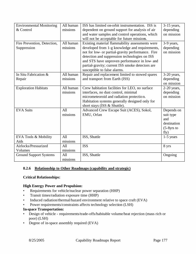
8/25/2005 Capability Roadmaps Report Page 177
Environmental Monitoring & Control
All human missions
ISS has limited on-orbit instrumentation. ISS is dependent on ground support for analysis of air and water samples and control operations, which will not be acceptable for future missions.
3-15 years, depending on mission
Fire Prevention, Detection, Suppression
All human missions
Existing material flammability assessments were developed from 1-g knowledge and requirements, not for low- or partial-gravity performance. Fire detection and suppression technologies on ISS and STS have unproven performance in low- and partial-gravity; current ISS smoke detectors are susceptible to false alarms.
3-9 years, depending on mission
In Situ Fabrication & Repair
All human missions
Repair and replacement limited to stowed spares and transport from Earth (ISS)
3-20 years, depending on mission
Exploration Habitats All human missions
Crew habitation facilities for LEO, no surface interfaces, no dust control, minimal micrometeoroid and radiation protection. Habitation systems generally designed only for short stays (ISS & Shuttle).
2-20 years, depending on mission
EVA Suits All missions
Advanced Crew Escape Suit (ACES), Sokol, EMU, Orlan
Depends on suit type and destination (5-8yrs to fly)
EVA Tools & Mobility Aids
All missions
ISS, Shuttle 1-5 years
Airlocks/Pressurized Volumes
All missions
ISS 8 yrs
Ground Support Systems All missions
ISS, Shuttle Ongoing
8.2.6 Relationship to Other Roadmaps (capability and strategic) Critical Relationships: High Energy Power and Propulsion: • Requirements for vehicle/nuclear power separation (HHP) • Transit times/radiation exposure time (HHP) • Induced radiation/thermal/hazard environment relative to space craft (EVA) • Power requirements/constraints affects technology selection (LSH) In-space Transportation: • Design of vehicle - requirements/trade-offs/habitable volume/heat rejection (mass rich or
poor) (LSH) • Degree of in-space assembly required (EVA)
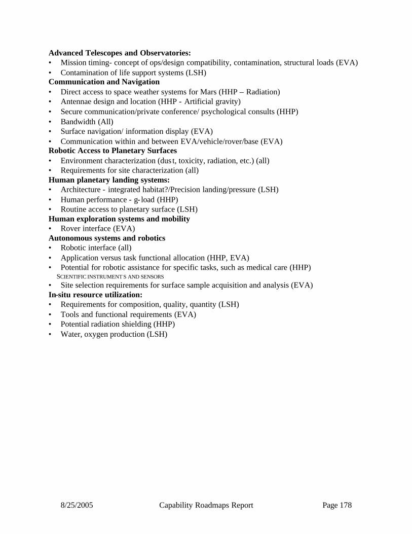
8/25/2005 Capability Roadmaps Report Page 178
Advanced Telescopes and Observatories: • Mission timing- concept of ops/design compatibility, contamination, structural loads (EVA) • Contamination of life support systems (LSH) Communication and Navigation • Direct access to space weather systems for Mars (HHP – Radiation) • Antennae design and location (HHP - Artificial gravity) • Secure communication/private conference/ psychological consults (HHP) • Bandwidth (All) • Surface navigation/ information display (EVA) • Communication within and between EVA/vehicle/rover/base (EVA) Robotic Access to Planetary Surfaces • Environment characterization (dus t, toxicity, radiation, etc.) (all) • Requirements for site characterization (all) Human planetary landing systems: • Architecture - integrated habitat?/Precision landing/pressure (LSH) • Human performance - g- load (HHP) • Routine access to planetary surface (LSH) Human exploration systems and mobility • Rover interface (EVA) Autonomous systems and robotics • Robotic interface (all) • Application versus task functional allocation (HHP, EVA) • Potential for robotic assistance for specific tasks, such as medical care (HHP)
SCIENTIFIC INSTRUMENT S AND SENSORS • Site selection requirements for surface sample acquisition and analysis (EVA) In-situ resource utilization: • Requirements for composition, quality, quantity (LSH) • Tools and functional requirements (EVA) • Potential radiation shielding (HHP) • Water, oxygen production (LSH)

8/25/2005 Capability Roadmaps Report Page 179
Figure 8.4aCapability Roadmap: Human Health & Support Systems
8.1 Human Health & Performance
8.0 Human Health & Support Systems(Key Events/Milestones)
2005 2010 20202015
Key Exploration Architectural Assumptions
8.2 Life Support & Habitation
8.3 Extra Vehicular Activity
CEV Demo
Un-crewed CEV
Lunar landing site(s)
Crewed CEV Lunar sorties begin
Long Duration MoonMars Sample
ReturnMars Human
PrecursorMars
Science Lab
CEV Crew Exposure Limits 8.1.1
Lunar Sortie Crew Exposure Limits
Lunar Multi-functional shielding materials specs
Long Duration Moon Crew Exposure Limits
Mars multi-functional shielding materials specs
CEV Medical Data System
Lunar Sortie Medical Data System
Long Duration Moon Medical Data System
Candidate CM Suite
Validated (ISS) CM Suite
Artificial Gravity Decision Package
Long duration Moon CM Suite decision
Advanced Life Support Systems for Short Duration Transit Missions
Life Support and Habitation Systems for Short Duration Transit
Vehicle - CEV
Life Support and Habitation Systems for
Short Duration Lunar Surface Missions –
Lunar Sortie
Life Support and Habitation Systems for
Long Duration Lunar Surface Missions
Life Support and Habitation Systems for Long Duration Transit
Missions – Mars Vicinity
Environmental Monitoring and Control Systems for Short Duration
Transit Missions
Contingency Response Systems for Short Duration Transit Missions
Habitation Systems for Short Duration Transit Missions
Integrated Ground Based and Flight Testing
Advanced Life Support Systems for
Short Duration Lunar Surface Missions
Environmental Monitoring and Control Systems for
Short Duration Lunar Surface Missions
Contingency Response Systems for Short Duration
Lunar Surface Missions
Habitation Systems for Short Duration Lunar
Surface Missions
Integrated Ground Based and Flight Testing
Advanced Life Support Systems for Long Duration Lunar
Surface Missions
Environmental Monitoring and Control
Systems for Long Duration Lunar Surface
Missions
Contingency Response Systems for Long
Duration Lunar Surface Missions
Habitation Systems for Long Duration Lunar
Surface Missions
Integrated Ground Based and Flight
Testing
Advanced Life Support Systems for Long Duration Mars Transit
Missions
Environmental Monitoring and Control Systems for Long Duration
Mars Transit Missions
Contingency Response Systems for Long Duration Mars Transit
Missions
Habitation Systems for Long Duration Mars Transit Missions
Integrated Ground Based and Flight Testing
CEV Medical System Lunar Sortie Medical System
Long Duration Moon Medical System
CEV Crew Select-in/ Select-out Criteria
Long Duration Moon Crew Select-in/ Select-out Criteria
Artificial Gravity Decision Package
In-Space EVA Tools and Mobility Systems
In-space EVA Suit System
Short Duration Lunar EVA Surface System
Long Duration LunarEVA Suit System
Long Duration Lunar EVA Tools & Mobility Systems
In-space EVA System Long Duration LunarEVA Suit System
In-Space Vehicle I/F Systems
Short Duration Lunar EVA Suit System
Short Duration Lunar EVA Tools& Mobility Systems
Long Duration Lunar Vehicle Systems (Airlocks..)
Short Duration Lunar Vehicle Systems (Airlocks, Rover/Hab I/F Systems)
Capability/Subcapability/Major Accomplishment
Capability/Subcapability/Demonstrated or established
CRM Milestone/Mission
Major Decision
Range of Dates
Development Timelines
Legend
Capability/Subcapability/Major Accomplishment
Capability/Subcapability/Demonstrated or established
CRM Milestone/Mission
Major Decision
Range of Dates
Development Timelines
Legend
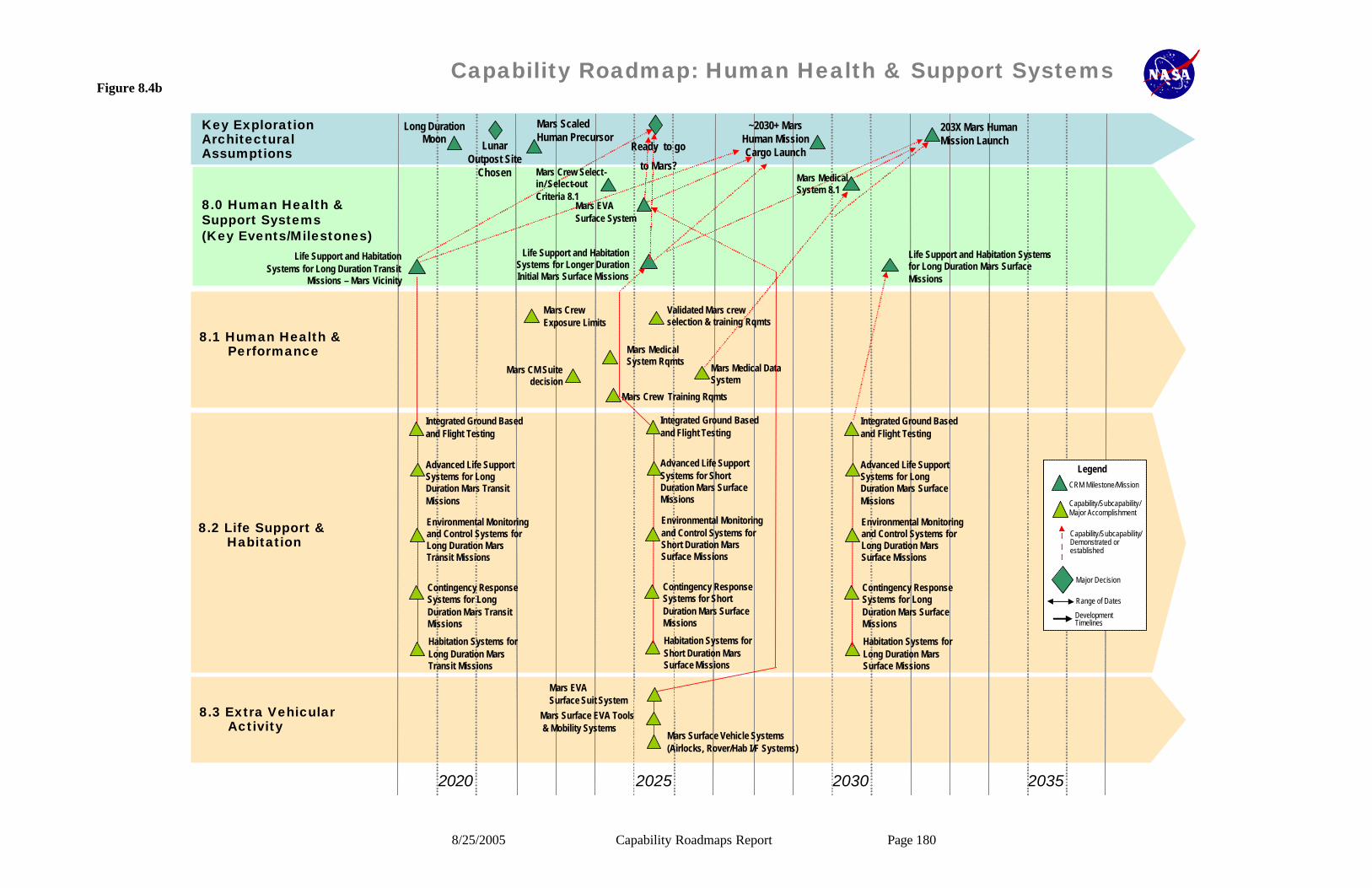
8/25/2005 Capability Roadmaps Report Page 180
Figure 8.4bCapability Roadmap: Human Health & Support Systems
8.1 Human Health & Performance
8.0 Human Health & Support Systems(Key Events/Milestones)
2020 2025 20352030
Key Exploration Architectural Assumptions
8.2 Life Support & Habitation
8.3 Extra Vehicular Activity
Lunar Outpost Site
Chosen
Mars Scaled Human Precursor
Ready to go
to Mars?
~2030+ Mars Human Mission Cargo Launch
203X Mars Human Mission Launch
Long Duration Moon
Mars Crew Exposure Limits
Mars Crew Training Rqmts
Validated Mars crew selection & training Rqmts
Mars CM Suite decision
Life Support and Habitation Systems for Long Duration Transit
Missions – Mars Vicinity
Life Support and Habitation Systems for Longer Duration Initial Mars Surface Missions
Life Support and Habitation Systems for Long Duration Mars Surface Missions
Advanced Life Support Systems for Long Duration Mars Transit Missions
Environmental Monitoring and Control Systems for Long Duration Mars Transit Missions
Contingency Response Systems for Long Duration Mars Transit Missions
Habitation Systems for Long Duration Mars Transit Missions
Integrated Ground Based and Flight Testing
Advanced Life Support Systems for Short Duration Mars Surface Missions
Environmental Monitoring and Control Systems for Short Duration Mars Surface Missions
Contingency Response Systems for Short Duration Mars Surface Missions
Habitation Systems for Short Duration Mars Surface Missions
Integrated Ground Based and Flight Testing
Advanced Life Support Systems for Long Duration Mars Surface Missions
Environmental Monitoring and Control Systems for Long Duration Mars Surface Missions
Contingency Response Systems for Long Duration Mars Surface Missions
Habitation Systems for Long Duration Mars Surface Missions
Integrated Ground Based and Flight Testing
Mars Medical System 8.1
Mars Crew Select-in/ Select-out Criteria 8.1
Mars Medical System Rqmts
Mars Medical Data System
Mars EVA Surface Suit System
Mars EVA Surface System
Mars Surface Vehicle Systems (Airlocks, Rover/Hab I/F Systems)
Mars Surface EVA Tools& Mobility Systems
Capability/Subcapability/Major Accomplishment
Capability/Subcapability/Demonstrated or established
CRM Milestone/Mission
Major Decision
Range of Dates
Development Timelines
Legend
Capability/Subcapability/Major Accomplishment
Capability/Subcapability/Demonstrated or established
CRM Milestone/Mission
Major Decision
Range of Dates
Development Timelines
Legend

8/25/2005 Capability Roadmaps Report Page 181
8.3 Summary The capabilities described in the Human Health and Support Systems Roadmap will enable safe, sustained, and productive human exploration. Research and technologies to reduce human health risks to acceptable standards and develop semi-autonomous medical care systems will serve to maintain crew health and safety for exploration missions. Closed-loop air, water and food systems will greatly reduce logistics for the Environmental Control and Life Support System (ECLSS), making missions more feasible and sustainable. Robust EVA surface suits, in-space suits, and associated technologies will allow crewmembers to complete all EVAs required on the missions. These roadmaps were developed in the absence of several key architectural and mission decisions, and would likely need to be adjusted in timing and emphasis, but not greatly in scope, to be accurate. For example, strategic decisions, such as the degree to which long duration lunar missions could be used as flight analogs for testing life support systems will affect the capability development for Mars missions. Other key programmatic decisions including the availability and access to ISS as a test bed and research platform will change the roadmaps, particularly in the Human Health and Performance area, in the next 10 years. The roadmap graphics in this summary are very high level and represent the roll-up of capabilities from 19 detailed subcapability roadmaps that were presented to the National Research Council. Subject matter experts, including NASA personnel and contractors, academics, and industrial colleagues, assisted with the development of the content for the roadmap, with review and direction of the Human Health and Support Systems Roadmap team members. The elements of the Human Health and Support Systems have many significant and complex interfaces and relationships to the spacecraft system elements. It is expected that these rich relationships will be described and managed through exploration systems engineering and integration. It is clear that a key element for success of Human Exploration is described with these roadmaps. It is expected that the contents of the Human Health and Support Systems roadmaps will be incorporated into the program and project plans that are used to manage implementation. The success of these roadmaps will enable humans to achieve the priority goals of the Vision for Space Exploration.
8/25/2005 Capability Roadmaps Report Page 182
NASA
Capability Road Map (CRM) 9
Human Exploration Systems and Mobility
Executive Summary
Chair: Chris Culbert, NASA JSC Co-Chair: Jeff Taylor, University of Hawaii
Coordinators
Directorate
Betsy Park NASA ESMD Gene Trinh, NASA ESMD
John Mankins, NASA ESMD
APIO
Tom Inman, NASA MSFC
Team Members
NASA/LANL
Ken Baker, NASA JSC Jim Blacic, LANL (ret)
John Dorsey, NASA LaRC Rick Eckelkamp, NASA JSC
David Korsmeyer, NASA ARC Dennis Lawler, NASA JSC
Rud Moe, NASA GSFC Jeff Patrick, NASA JSC
June Zakrajsek, NASA GRC Wayne Zimmerman, NASA JPL
Academia
Larry Taylor, Univ of Tennessee
Industry
David Adlis, Aerospace Corp. David Carrier, Lunar Geotechnical
Institute Wendell Chun, Lockheed Martin
Jud Hedgecock, Oceaneering Mark Henley, Boeing
Robert Yowell, Aerospace Corp.

8/25/2005 Capability Roadmaps Report Page 183
9 Human Exploration Systems and Mobility (Roadmap 9)
9.1 General Capability Overview 9.1.1 Capability Description
There is a wide-ranging set of capabilities that support human exploration activities in space and on planetary surfaces. It includes capabilities to allow scientific observations, resource & site evaluation, instrument deployment, facility/spacecraft assembly & servicing, and efficient, affordable mission operations. This capability is divided into four major divisions:
• Crew-Centered Operations: Enables local planning and control of operations without extensive ground support to provide safe, efficient, and cost-effective operations.
• Human Exploration: Enables efficient access to exploration targets, with in situ observations & analyses.
• Mobility: Enables movement and transport of crew and equipment in space and on planetary surfaces.
• Assembly, Deployment, & Servicing: Enables construction and servicing in space and on planetary surfaces.
9.1.2 Benefits
• Supports human presence for long-duration space flight or missions to planetary surfaces • Enhances scientific exploration and discovery through:
o Deployment of complex scientific instrumentation in space, such as large telescopes o Installation of instrumentation and sophisticated scientific facilities on planetary
surfaces o Enhanced human access to scientific targets on planetary surfaces o Global access on the Moon, Mars, and other planetary bodies
• Enables human-robot partnerships to make the most efficient and cost-effective use of each partner
• Reduces operations and sustaining engineering costs by moving more responsibility and capability to the crew, including effective use of autonomous systems
• Allows constructing, assembling, and deploying components to create and evolve larger devices/instruments/structures, which enables missions with more ambitious science activities
• Enables affordability, reusability and sustainability through modularity & standardization of spacecraft components, interfaces, agent operations & capabilities, and infrastructure
• Uses a modular approach to extend system life and upgrade functionality via in-situ service and maintenance

8/25/2005 Capability Roadmaps Report Page 184
9.1.3 Key Architecture / Strategic Decisions
Key Architecture/Strategic Decisions
Date Decision Needed
Impact of Decision on Capability
(Capability Development Required) Adopt crew-centered operational strategy Now Requires local decision making and autonomy
Evaluate the Moon as a proving ground for Mars exploration
Now Affects design of systems for assembly, construction, servicing, mobility, human exploration activities; places extra requirements on initial lunar capabilities
Decision on continuous, long-term sustainable lunar operation vs. intermittent operation
2006 Drives infrastructure development: modularity, servicing, assembly, mobility
Decision on launch capabilities for cargo to LEO 2007 Affects extent of assembly and deployment in space
Assess role that robotics play in human exploration missions
2008 Human and robotic teaming for assembly, servicing, ISRU & science activities
Develop architecture for ISRU 2009 ISRU requires prospecting and added infrastructure for servicing, assembly, construction, and mobility
Decide between a single lunar surface base rather than multiple locations
2008 Drives need for regional (100s of km) mobility, planetary surface navigation and communication, and build-up of infrastructure (servicing, assembly, etc.)
Decide on priority for access to small bodies such as NEOs and Martian moons
2010 Requires specialized capabilities for low-g environment and unconsolidated regolith
Develop Gateway-type facilities at Earth -Moon libration point and/or other locations
2010 Supports in-space assembly, servicing, and staging for low-energy transfer to Earth-Sun L-points; lunar surface support; post-ISS bioastronautics facility; candidate precursor to Mars transfer habitation.
9.1.4 Major Technical Challenges
2006-2010 o Design/Build crew-centered command, control and operations architecture and processes for the entire Exploration
Program to reduce reliance on ground support and improve affordability. o Design CEV for crew-centered operations o Develop autonomous software to enable safe crew command and control o Develop adaptable human exploration operations control architecture
• Design common modular mobility and surface robotic systems for severe environments (e.g., lunar polar temperatures, dust, etc.) to enable affordable and sustainable Moon and Mars surface exploration
o Must be environmentally resistant, dormancy tolerant, serviceable & maintainable
• Develop methods and technologies to enable local crew-robot interactions and remote robot control o Scientific exploration with robotic systems via telepresence and supervised autonomous control
2010 – 2020
• Support a sequence of large (> 20 meter aperture), complex, very-long duration, optical systems.
• Field long-life, reusable (cost-efficient) systems that do not require a large workforce or significant crew time to maintain:
o Exploration spacecraft (including all spacecraft elements) for Moon, Mars, small bodies, etc. o Planetary surface exploration infrastructure and systems.
• Develop cost efficient, local generation, storage & distribution of consumables (i.e., through use of ISRU) for in-space and planetary systems.

8/25/2005 Capability Roadmaps Report Page 185
• Develop robust communication & navigation systems for lunar vicinity (lunar orbit and lunar surface)
• Perform long-duration, extended-range human exploration of the Moon from a central base o Radiation protection, power systems, pressurized mobile system with airlock, ECLSS o Wide variety of terrains, locations, lighting, and thermal conditions
• Develop techniques for sub-surface sensing, access, and sampling o Planetary environments, with planetary protection o Near-Earth objects and Martian moons (low-g drilling, geophysics, landing, etc.)
2020 and Beyond • Enable rapid human transportation on the surface of Moon and Mars
o Example: Sub-orbital “hopper” o Example: Mars aeroplane
• Provide surface-based science labs with state-of-the-art instrumentation
• Perform sample and resource recovery from intermediate depths (10-300 m)
• Deploy global geophysical instrument arrays for subsurface exploration
9.1.5 Key Capabilities and Status 9.1.5.1 Crew-Centered Operations The challenge of NASA’s Vision for Space Exploration is significantly different from the Apollo program wherein the object was to land Americans on the Moon before the Soviet Union. Many innovations in program management, space operations, and hardware and software engineering were developed methodically in a period of enthusiasm and national competition. Costs and extended operations, however, were not priorities in these pursuits. In subsequent programs, NASA has frequently concentrated on vehicle hardware development, leaving to an unspecified future development efficient operational systems that would lower total life-cycle costs. To have a successful and flourishing exploration program, we must change how we perform command and control. It is necessary to build, beginning with the CEV, a robust human and robotic exploration program that moves from ground-centered control to crew-centered control. Missions must be designed to be as self-sufficient as practical. Operational control will be in the field, in space or on a planetary surface. Distributed ground support teams and centers will be used on a non-continual basis to augment what are essentially crew-controlled and crew-led operations. In this operational concept, the crew will be at the center of command and control activities, use vehicles with autonomous navigation, guidance and control and autonomous system health monitoring, perform weekly task planning and daily scheduling, perform the majority of system error recoveries using in situ capabilities and, assisted by robots, perform scientific, exploration, and construction activities in free space and on planetary surfaces. Ground control will perform strategic and tactical monthly and yearly planning, permission contingency analyses, trans-lunar and interplanetary trajectory design, and vehicle checkout and launch preparation, provide traffic control for launching and landing vehicles, provide on-call system expertise and failure analyses; develop crew training and instructional programs and data mostly for uplink for crew field use, develop robotic execution scripts, and, when practical and cost-effective, provide remote robotic control.
8/25/2005 Capability Roadmaps Report Page 186
9.1.5.2 Human Exploration Activities The ability to collect samples of planetary solid, liquid, and gaseous materials is paramount for scientific analysis, as well as for ISRU assessment and measurement of civil engineering properties. Samples may consist of soils or other small-grained aggregates from the surface or subsurface, small to large rocks from surface or trench exposures, subsurface drill cores, atmospheric gas, and surface or subsurface liquids. A drilling capability is needed to access depths below those that can be achieved by trenching. The required depth of a drilling capability will vary substantially, ultimately exceeding hundreds of meters. In order to preserve specific characteristics of some samples for subsequent measurement, there is a requirement to maintain in situ environmental conditions of temperature, pressure, orientation, or other natural aspects during the acquisition and storage process. For most samples, there is also a requirement to mitigate chemical and biological forward and backward contamination during acquisition and storage. The capability for direct sensing of planetary surfaces is divided into direct contact observation and remote observation. Each of these surface-sensing modes can be further distinguished as either passive or active sensing. In passive sensing, natural energy emanates or is reflected from a planetary surface and is collected by a sensor either in direct contact with or remotely located near the surface. An active observation involves transmission of energy from an artificial source to the planetary surface where it interacts with the material of the surface and produces a characteristic signal as the result of some active process. Remote sensing of planetary materials can be orbital, suborbital/aerial or subsurface. Analysis of observations may occur in the field, but are more likely to be done in a well-equipped surface base. Telerobotic exploration and less frequent human surface sorties will require a robust operations protocol system for efficiency and safety. 9.1.5.3 Mobility This area focuses on providing human, equipment, and surface transportation in space and on planetary surfaces. These capabilities are essential for safe and efficient human space exploration and operations. In space, mobility enables movement and positioning of astronauts and equipment during construction and maintenance of a vehicle, and deployment of scientific and monitoring equipment such as space telescopes and other structures. Surface mobility is crucial for accomplishing many tasks ranging from site preparation and construction, to local transportation, to prolonged exploration sorties. Our CRM provides an evolutionary approach such that the required capabilities expand as distance from the base of operations increases. Surface mobility capabilities assist astronauts in day-to-day local operation, maintenance, safe local area exploration, and rescue. Systems capable of moving and hauling regolith for landing and habitat site preparation, radiation shielding, and resource mining are also needed. For long-distance exploration, systems must be capable of safe, robust operations and autonomous deployment. Long-duration transportation that is coordinated with rapid transportation permits minimal crew radiation exposure and maximal crew EVA efficiency. Rapid transport includes infrastructure-based and sub-orbital hopper concepts. All of these mobility abilities rely upon enhanced- and expanded-bandwidth communications and increased accuracy navigation infrastructure.
8/25/2005 Capability Roadmaps Report Page 187
9.1.5.4 Assembly, Deployment, and Servicing Many future in space and planetary surface vehicles, platforms, and systems for exploration missions are large, complex, massive, and cannot be placed in orbit in a single launch, which therefore would require assembly. In order to achieve an affordable and sustainable permanent presence in space, it will be imperative to design vehicles with long lifetimes that can be upgrade. Servicing, or the ability to inspect and detect faults, perform routine maintenance, repair & re-supply, and perform system upgrades becomes a necessary capability. Assembly and servicing of space-exploration vehicles and systems will entail a broad range of in-space and planetary operational capabilities, including inspection, component transfer & storage, fluid handling, fabrication & construction, repair, servicing, disassembly & refurbishment, and test & verification. Efficient execution of assembly and servicing functions will require supporting infrastructure, mobile dexterous agents (both human and robotic) to perform the operations, modular components, verification test equipment, and operations-scenario planning, simulations, and training. An occupied “gateway” facility in space may, in addition, satisfy requirements for post-ISS human health and bioastronautics, serving as a precursor or demo for the habitat for the human missions to Mars.

8/25/2005 Capability Roadmaps Report Page 188
9.1.6 Key Capabilities and Status
Capability/Sub-Capability Enabled
Mission or Roadmap
Current State of Practice
Estimated Development Time
Crew-Centered Operations
Crew-centered, in-situ task planning and adaptation
All, starting with CEV
Ground-based: ISS activity planner, MER activity planner, NASA planning systems
2-4 yrs initial system 5-9 yrs for ground/flight integrated system
Skill-based and in-field just-in-time training for crew
All, starting with CEV
Facility-based VR and conventional simulation-based trainer
2-4 yrs initial system 4-7 yrs for ground/flight integrated system
Human-robotic teaming and coordinated interaction
All surface and on-orbit assembly, missions
Astronaut Shuttle-RMS interaction; NASA experimental systems
4-6 yrs initial system 7-10 yrs for ground/flight integrated system
Automated-systems fault management: graceful degradation, recovery, and reconfiguration (Intelligent System Health Management)
All, starting with CEV
Ground-based after-the-fact. Freedom Integrated Station Executive, Livingstone2 of EO-1 spacecraft
2-4 yrs initial system 7-10 yrs for full ground/flight integrated system
Automatic documentation of crew, robot, and system activities.
All, starting with CEV
Elementary capture and storage of data, video, image, and audio clips
3-5 yrs initial system 7-10 yrs for ground/flight integrated system
Order of magnitude faster space-qualified computer systems
All, starting with CEV
1800+ MIPS rad hardened (Maxwell SCS750)
2-4 yrs initial system 4-8 yrs for high end system
Supervisory robotic control and telepresence
All missions ISS rudimentary, Robonaut, MER, Orbital Express
4-6 yrs initial system 7-10 yrs for ground/flight integrated system
Increased crew situational Awareness for spacecraft and operational states
CEV, surface EVA
Shuttle MEDS; military aircraft cockpits, NASA experimental system
3-4 yrs for CEV 5-10 yrs for full lunar integrated system
Human Exploration
Undisturbed sampling (retaining natural state of solid, liquid, gas)
Moon, Mars, and small bodies
Apollo drive tubes Apollo indium seals Earth drill core
2 yrs: volatile preservation 4 yrs: ice preservation
Trenching & habitat burial for radiation protection
Moon, Mars Apollo trench tool Viking & Surveyor scoops
3 yrs: terrestrial demo 7 yrs: lunar demo
Drilling (shallow, intermediate, deep) Moon, Mars, and small bodies
Apollo motorized drill (3 m) cometary drill (0.5 m) Earth ice & deep sea cores (km)
3 yrs: intermediate depth demo on Earth 5 yrs: in space demo

8/25/2005 Capability Roadmaps Report Page 189
Key Capabilities and Status (continued)
Capability/Sub-Capability Mission or road map Enabled
Current State of Practice
Development Time
Orbital/Aerial remote sensing Moon, Mars, and small bodies
Many lunar & Martian remote sensing platforms
3 yrs: prototype
Surface Sensing: Direct contact & stand-off (e.g., laser ablation)
Moon, Mars, and small bodies
MER Mössbauer and APXS LIBS prototype
3 yrs: prototype 5 yrs: flight ready
Subsurface sensing Moon, Mars, and small bodies
Apollo seismic, fields & particles; E-M sounder Arecibo radar sounding Earth: spectral analysis of surface waves, gravity, ground penetrating radar, electrical conductivity
3 yrs: prototype 5 yrs: flight ready
In-Situ Analysis; geologic field context, surface composition, soil engineering properties
Moon, Mars, and small bodies
Apollo soil measurements, field geologic analysis
5 yrs: instrument prototypes and operation protocols 7 yrs: flight ready
Analysis at base; geological, biological, and materials -science sample preparation and curation
Moon, Mars Antarctic science; Lunar Receiving Lab
5 yrs: prototype 7 yrs: flight ready
Mobility
100 MBPS space comm link (applies to all areas)
All human missions 1MBPS
4-6 years
Exploration vehicle autonomous navigation
Moon, Mars, all in-space missions
NSTS rendezvous, ISS GPS
2 yrs to develop software 4 yrs to demo on planetary surface
Walking and climbing aids Moon, Mars, and small bodies
Apollo (None); mountaineering & walking on Earth
2 yrs after suit development
Mobile support platforms (pack mule)
Moon, Mars, all in-space missions
Mobile Data-Relay Station, carriers for equipment & resources
4-6 yrs
Personal transport Moon, Mars, all in-space missions
In-Space: SAFER Surface: None, adapt “Segway”
3-5 yrs for demo in relevant Lunar Environment

8/25/2005 Capability Roadmaps Report Page 190
Key Capabilities and Status (continued)
Capability/Sub-Capability Mission or road map Enabled
Current State of Practice
Development Time
Surface construction equipment Moon, Mars Earth-based construction equipment, none in space
5-7 yrs per vehicle
Moving crew quickly from 10 – 1000 km
Moon, Mars, all in-space missions
Ground demos, but none in space
10-15 yrs
Long-duration surface transport Moon, Mars No in-space demos 6-8 yrs
Autonomous drive operations
Moon, Mars None; Terrestrial applications 2 km/hr – 32 km/hr
8-10 yrs to demo in relevant lunar environment
Multi-mobility system cooperation
Moon, Mars, all in-space missions
No automated surface or in-space mobility system-system cooperation.
5-7 yrs
Assembly, Deployment & Servicing
In-space and planetary surface assembly and verification
All habitats, vehicles, platforms, telescopes
In space: ISS Planetary surface: None
3 yrs.- Assembly & refueling demo 7 yrs.- Small precursor 12 yrs.- Full capability
In-space & planetary surface inspection, servicing, and maintenance
All habitats, vehicles, platforms, telescopes
In space: Hubble, ISS, Orbital Express Planetary Surface: None
3 yrs.- Assembly & refueling demo 7 yrs.- Small precursor 12 yrs.- Full capability
Modular systems and interface standards
All habitats, vehicles, platforms, telescopes
Explorer Platform (modularity) ISS ORUs, Orbital Express Standards: GEO commsats (utilities)
First generation: 2 years before first use (CEV PDR)
Multi-purpose tools and advanced robotics
All habitats, vehicles, platforms, telescopes
Tools: Hubble Servicing & ISS EVA Robotics: SRMS, SSRMS, SPDM, Robonaut, Ranger, Orbital Express
Tools: 1 – 3 years Robotics: 3 – 5 years
In-space depots and infrastructure facilities
All vehicles platforms, telescopes
ISS Low Earth Orbit – 5 yrs Beyond LEO – 10yrs Planetary Surface – 10yrs

8/25/2005 Capability Roadmaps Report Page 191
9.2 Roadmap Development 9.2.1 Legacy Activities and Roadmap Assumptions This roadmap activity brought together, for one of the first times in a single document, the disparate capabilities necessary for effective human operations on the lunar and Martian surface, and in space. However, the group did take advantage of many previous studies, papers, and relevant team experience to create the roadmap material. In the process of developing the roadmap material, the team considered and agreed to a number of specific mission or architecture elements that were drivers for many aspects of the roadmap. Table 9.1 - Assumptions Assumptions of Mission Architecture Long duration (> 180 day) human presence on the lunar surface Eventual human presence on the surface of Mars Reliable access to all ‘useful’ points in the Earth – Mars system Gateway-type facility on-orbit to support assembly/servicing, lunar exploration, space ops and medicine Assumptions on Other Capabilities Power readily available (100s of KW) Thermal-control, heat-rejection technologies considered by other teams Communications – very-high bandwidth will be provided at least locally Locally information-rich and information-accessible
Other teams address cosmic & solar flare radiation shielding; we consider impacts for exploration activities
HESM Capability Assumptions Human safety considerations are critical; systems will be fault tolerant Systems must become capable of at least supervised autonomy Local-science analysis capability and sample return both are necessary Infrastructure-rich locations on the surface with sorties going out from them Access to the entire planetary surface is vital Human productivity/efficiency considerations, <25% of crew time spent on maintenance & housekeeping Modularity, assembly, and maintenance will be used & standards developed for common, broad application
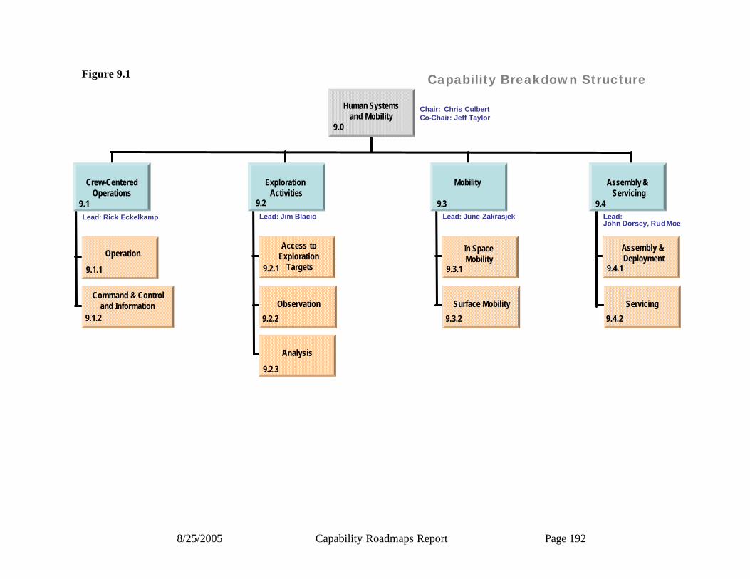
8/25/2005 Capability Roadmaps Report Page 192
Capability Breakdown Structure
Crew-Centered Operations
9.1Lead: Rick Eckelkamp
Operation
9.1.1
9.1.2
Command & Controland Information
Lead: Jim Blacic
Access to Exploration
Targets9.2.1
9.2.2
Observation
Analysis
9.2.3
Lead: June Zakrasjek
In SpaceMobility
9.3.1
9.3.2
Surface Mobility
Lead:John Dorsey, Rud Moe
Assembly & Deployment
9.4.1
9.4.2
Servicing
9.2 9.3 9.4
Exploration Activities
Mobility Assembly &Servicing
Human Systems and Mobility
Chair: Chris CulbertCo-Chair: Jeff Taylor
9.0
Figure 9.1
8/25/2005 Capability Roadmaps Report Page 193
9.2.2 Roadmap Logic The capability roadmap in this report is a summary level roadmap. This summary level roadmap includes only a roll up of the key sub-capabilities milestone readiness to support a particular mission requirement. Detailed sub-capability and technology roadmaps showing the technology progression and sub-capability development were presented to the NAS and are available in the document sharing system. In the top blue banner of the roadmap, there are those key missions that are pertinent to the roadmap among those derived from the April 15, 2005 interim document delivered by the strategic roadmaps and displayed in the CRM Planning Milestones Chart. The green banner below represents a summary rollup of key capabilities from each of the various capability breakdown structure elements. The peach colored swim-lanes represent the individual top level capability breakdown structure element and the sub-capabilities within this roadmap. The triangles represent the date that the capability is ready to support a given mission, and the diamonds represent decision points.

8/25/2005 Capability Roadmaps Report Page 194
Capability Roadmap: Human Exploration Sys. & Mobility (HESM)
9.1 Crew Centered Operations
9.4Assembly & Servicing
9.0 Human Exploration Sys. & Mobility Capability Road Map(Key Events/Milestones)
2005 2010 20202015
Key Exploration Architectural Assumptions
2008CEV Demo2008 LRO
20102nd Lunar
Mission
2011Uncrewed CEV
2011JWST
2012SIM
2012Lunar LandingSite Decision
2014 CrewedCEV LEOLISA
2016 MSA
TPF-C
CON-X
2017 Lunar Sorties
2019 TPF-IJDEM
2020 Long-DurationLunar Missions
PlanningSoftware
Robotic Assembly/Servicing Modular Systems
Robotic InfrastructureBuilding Begins
Moon Surface Mobility 10km
In Space Mobility
On-Surface Training
Field Science DataExecution Support
Intermediate Drilling & Explosives
ShallowDrilling Trenching
Remote Site Sensing & Support
PlanningSoftware
Re-PlanningContingency Analysis Intercenter Command &
Control PlanningOn SurfaceTraining
Field Science Data & Execution Support
Cryogenic Regolith Access
Seal Volatile In RegolithScooping
Intermediate Drilling
ExplosivesSurface RemoteObservation
Remote SensingAnalyticalInstrumentation Surface Lab
Deep Subsurface Observation
Radio Observation from Surface
Surface MobilityImmediate Vicinity (10km)
Lunar Mobility Upgrade
In Space Mobility Upgrade
Robotic Assembly LEO
Robotic Servicing of Simple Modular Systems
Assembly of systems at L1
Planned Servicing
Prospecting Fields Selection
Command & Control Support Infrastructure Development (Surface & International
9.2 Exploration Activities
9.3 Mobility
In-Space Assembly
Capability/Subcapability/Major Accomplishment
Capability/Subcapability /Demonstrated or
established
CRM Milestone/Mission
Major Decision
Range of Dates
Development Timelines
Legend
Capability/Subcapability/Major Accomplishment
Capability/Subcapability /Demonstrated or
established
CRM Milestone/Mission
Major Decision
Range of Dates
Development Timelines
Legend
Figure 9.2a
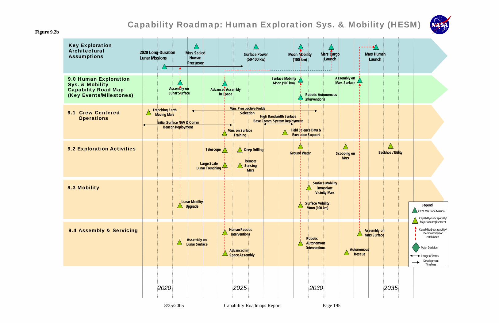
8/25/2005 Capability Roadmaps Report Page 195
Capability Roadmap: Human Exploration Sys. & Mobility (HESM)
9.1 Crew Centered Operations
9.2 Exploration Activities
9.3 Mobility
9.4 Assembly & Servicing
9.0 Human Exploration Sys. & MobilityCapability Road Map(Key Events/Milestones)
2020 2025 20352030
Key Exploration Architectural Assumptions
Mars Scaled Human
Precursor
Surface Power (50-100 kw)
Moon Mobility (100 km)
Mars Cargo Launch
Mars Human Launch
Assembly on Lunar Surface
Advanced Assembly in Space
Surface Mobility Moon (100 km)
Robotic Autonomous Interventions
Assembly on Mars Surface
Trenching Earth Moving Mars
Mars on Surface Training
Deep Drilling
Initial Surface NAV & Comm Beacon Deployment
Lunar Mobility Upgrade
Mars Prospective Fields Selection
High Bandwidth Surface Base Comm. System Deployment
Field Science Data & Execution Support
Ground Water Scooping on Mars
Backhoe / Utility
Remote Sensing
Mars
Telescope
Surface Mobility Immediate
Vicinity Mars
Large Scale Lunar Trenching
Surface Mobility Moon (100 km)
Assembly on Lunar Surface
Human Robotic Interventions
Advanced in Space Assembly
Robotic Autonomous Interventions
Assembly on Mars Surface
Autonomous Rescue
Capability/Subcapability/Major Accomplishment
Capability/Subcapability/Demonstrated or
established
CRM Milestone/Mission
Major Decision
Range of Dates
Development Timelines
Legend
Capability/Subcapability/Major Accomplishment
Capability/Subcapability/Demonstrated or
established
CRM Milestone/Mission
Major Decision
Range of Dates
Development Timelines
Legend
2020 Long-DurationLunar Missions
Figure 9.2b

8/25/2005 Capability Roadmaps Report Page 196
9.2.3 Relationship to Other Roadmaps (capability and strategic) This roadmap has significant relationships with the High-Energy Power and Propulsion, In-space Transportation, Advanced Telescopes and Observatories, Communication and Navigation, Robotic Access to Planetary Surfaces, Human Health and Support Systems, Autonomous Systems and Robotics, In-Situ Resource Utilization, and Systems Engineering. There is a moderate relationship with the remaining Capability Roadmaps. Acronym list CEV Crew Exploration Vehicle CRAI Capability Requirements Analysis and Integration CRM Capability Roadmap ECLSS Environmental Control Life Support System E-M Electro Magnetic EVA Extra Vehicular Activity GEO Geosynchronous Orbit GPS Global Positioning System ISRU In-situ Resource Utilization ISS International Space Station KW Kilowatt LEO Low Earth Orbit L-Point Libration Point MBPS Mega Bits Per Second MER Mars Exploration Rover MIPS Million Instructions Per Second NEO Near Earth Object NRC National Research Council NSTS National Space Transportation System ORU Orbital Replacement Unit PDR Preliminary Design Review Rad Radiation RMS Remote Manipulator System SPDM Special Purpose Dexterous Manipulator SRMS Shuttle Remote Manipulator System SSP Space Shuttle Program SSRMS Space Station Remote Manipulator System VR Virtual Reality

8/25/2005 Capability Roadmap Report Page 197
NASA
Capability Road Map (CRM) 10
Autonomous Systems, Robotics, and Computing (ASRC)
Executive Summary
Chair: James Crawford, NASA ARC Co-Chair: Doug Gage, DARPA (ret.) Deputy Chair: Paul Schenker, NASA JPL
Coordinators
Directorate
Harley Thronson NASA SMD Giulio Varsi, NASA SMD
APIO Jan Aikins, NASA ARC
Team Members
NASA / JPL / DOE
Steve Chien, ARC Ron Diftler, NASA JSC Dave Lavery, NASA HQ
Illah Nourbakhsh, NASA ARC Julia Loftis, NASA GSFC
Michel Ingham, NASA JPL Serdar Uckun, NASA ARC
Academia Dave Akin, University of Maryland
Red Whittaker, CMU Reid Simmons, CMU
Bob Full, UC Berkeley Brian Williams, MIT James Allen, IHMC
Michael Evangelist, CMU
Industry
Chris Leslie, USA Dan Clancy, Google (ex-NASA)
Additional reviews: Barry Fox, Boeing

8/25/2005 Capability Roadmap Report Page 198
10 Autonomous Systems, Robotics, and Computing Systems (Roadmap 10) 10.1 General Capability Overview 10.1.1 Capability Description The Autonomous Systems, Robotics, and Computing Systems (AR&C) capability roadmap details the autonomy, robotics, and computing technologies required for NASA spacecraft, robots, and human/robotic teams to achieve exploration and science mission objectives in harsh dynamic environments safely, dependably, and affordably. The roadmap includes autonomy for operations, integrated systems health management, robust execution of critical sequences (e.g., autonomous rendezvous and docking), autonomous process control, robotics for planetary exploration, human-robotic teaming for surface habitation and in-space operations, software validation and verification, and avionics systems. 10.1.2 Benefits The importance of AR&C is driven by two trends in NASA missions. First, both the exploration initiative and the space science programs increasingly require a presence on planetary surfaces. Compared to the orbital environment, the surface environment is less predictable, less understood, and much more dynamic. Many of the NASA-pacing AR&C requirements over the coming decades are driven by the fact that interactions between NASA spacecraft and surface environments will occur at faster timescales than the communication latencies back to Earth (a challenge not shared by private industry or other government agencies). Second, many upcoming mission tasks require NASA to address manipulation challenges that go beyond those accomplished in past missions. Examples include: drilling, in situ resource utilization, habitat construction, in-space maintenance and assembly, and in situ scientific analysis. Again, these tasks are dynamic on time scales that exceed communication latencies back to earth. This, in turn, creates NASA-pacing capability requirements in autonomous systems and robotics. The importance of AR&C capabilities is such that they enable NASA to carry out a broad range of missions that involve operation in harsh, dynamic environments (e.g., Mars, Titan, Europa, etc.), and/or involve challenging manipulation tasks. AR&C also includes several important capabilities that reduce mission costs and/or mission risks. These include: autonomy for operations, integrated vehicle health management, robust execution of critical sequences, software validation & verification, and avionics systems.1
10.1.3 Key Architecture / Strategic Decisions
The following Table 10.1 summarizes what the team considered to be the key architecture/strategic decisions that will impact capability requirements.
1 One of the principle comments the AR&C team received from our NRC review panel was that enough NASA missions fail due to cost and risk constraints that we should consider these “enhancing” capabilities to be as important for NASA as the enabling capabilities provided by AR&C.

8/25/2005 Capability Roadmap Report Page 199
Table 10.1 - Key Architecture / Strategic Decisions
Key Architecture/Strategic Decisions
Date Decision is Needed
Impact of Decision on Capability
Mission architecture for in-space portion of crewed Lunar missions (e.g., use of autonomous rendezvous & docking, in-space connection, etc.)
2007 for 2020
missions
Prioritization of autonomy and control for autonomous rendezvous and docking, robotics for in-space connecting, etc.
Mission architecture for Lunar surface operation (e.g., pre-placement of habitat, use of ISRU, etc.)
2007 for 2020
missions
Prioritization of autonomy for critical sequences in pinpoint EDL, autonomous checkout of assets before crew arrival, process control for ISRU, etc.
Command and control architecture for crewed Lunar exploration (e.g. location of capcom)
2006 for 2015
missions
Prioritization of automation to support crew-centered operations
Operational paradigm for Lunar surfaces operations in crewed missions (including both habitat construction and science activities)
2007 for 2020
missions
Prioritization of robotics for surface operation, level of autonomy for surface robotics, role of telerobotics, etc.
Major systems decision for crewed Mars missions (e.g., nuclear vs. chemical propulsion)
2012 for 2025
missions
Prioritization of autonomous process control for nuclear reactors and other systems
Mission architecture for observatories and universe missions
2007 for 2020
mission
Prioritization of in-space deployment / in-space construction, formation flying, interferometry, etc

8/25/2005 Capability Roadmap Report Page 200
10.1.4 Major Technical Challenges The following Table 10.2 contains what the team considered the top ten technical challenges affecting the area of autonomy, robotics and computing systems. These challenges are phased into three time frames 2006-2010, 2010 – 2020 and 2020 and beyond. Table 10.2 - Major Technical Challenges
2006-2010
• Robust autonomy for robotic surface operations. Upcoming lunar, Mars, and solar system missions will require a significant increase in speed and functionality vs. the MER baseline, and the performance of new tasks such as sample acquisition, drilling, life science experiments, and habitat construction, inspection, and maintenance.
• Largely automated spacecraft and habitat operations. Due to light-speed delays (and cost pressures), current ground-centric operational paradigms will not extend to exploration missions. Automation is required to enable crew-centered operations. This is important for both in-space and future surface operations.
• High-Fidelity Software-Simulation-Based Testing. Hardware- in-the-loop testing is the “gold standard” today for software validation. However, hardware is only available close to launch, and is always a limiting resource (especially when changes must be made close to the launch date). High-Fidelity software-simulation-based testing would support much larger test suites run more frequently without adverse impact to mission budgets and timelines.
2010 – 2020 • Prognostics. Prognostics refer to the ability to predict component and system
failures before they occur. This is critical for crewed missions involving many sub-systems operating far from Earth. It also allows cost effective positioning of replacement parts and cost effective use of preventative maintenance across NASA missions.
• Robust autonomy and robotics for deep drilling, aerobots, and cryobots. Unlike rovers, drills, aerobots and cryobots generally cannot handle faults by stopping and calling back to earth. Robust autonomy and robust hardware working together will be required. This requires an integration of integrated vehicle health management, robust execution, and robust on-board planning and fault recovery.

8/25/2005 Capability Roadmap Report Page 201
2010 – 2020 (continued)
• 10x decrease in major errors per line of source code. The number of source lines of code (sloc) in NASA missions has been increasing steadily over the last three decades. However, the number of mission-threatening errors per sloc has remained relatively constant. The inevitable result of these trends is a steady increase in the number of close calls and mission failures traceable to software errors. Improvements in software processes and software validation and verification are required to radically reduce the number of major errors per sloc. Improvements in validation and verification are particularly important for autonomous systems.
• Autonomous process control for drilling, nuclear reactors, ISRU, etc. Many terrestrial systems rely on constant human oversight. When these systems are incorporated into NASA missions this human oversight must be replaced by automated process control (either because of use on un-crewed missions or because crew time is a scarce resource). The most important mid-term examples include: drilling, control of nuclear reactors, and chemical plants for ISRU. In all of these cases there have been no comprehensive demonstrations of automated process control.
• In-orbit robotic inspection and maintenance. Many missions are ended prematurely due to failures of replaceable components or lack of propellant or coolant. Astronaut servicing is both expensive and risky. Proven, and relatively inexpensive, robotic maintenance would also allow instrument upgrades over the lifetime of expensive assets.
2020 and Beyond
• Autonomy for surface construction, pinpoint landing, and ISRU. The co-development of robotic surface construction, pinpoint landing, and ISRU would allow robotic precursor missions to prepare habitats and fuel supplies for cost-effective long-duration crewed missions to both the moon and Mars.
• In-orbit robotic construction. This would enable the next generation of observatories and basic science experiments. It also allows ongoing maintenance and upgrades of instruments on orbiting platforms.

8/25/2005 Capability Roadmap Report Page 202
Figure 10.1
Figure 10.1 - The number of lines of code in NASA missions grows exponentially but the number of mission-threatening errors per line of code is roughly constant. Not included in this graphic is the MER mission which required roughly 500,000 source lines of code.
Autonomous Systems and Robotics
8
1700
3
32
160430
1
10
100
1000
10000
Voyager(1977)
Galileo(1989)
Cassini(1997)
MPF(1997)
Shuttle(2000)
ISS (2000)
Mission
Lin
es o
f C
od
e (T
ho
usa
nd
s)
Constant Error Rate
Software development is a significant cost driver
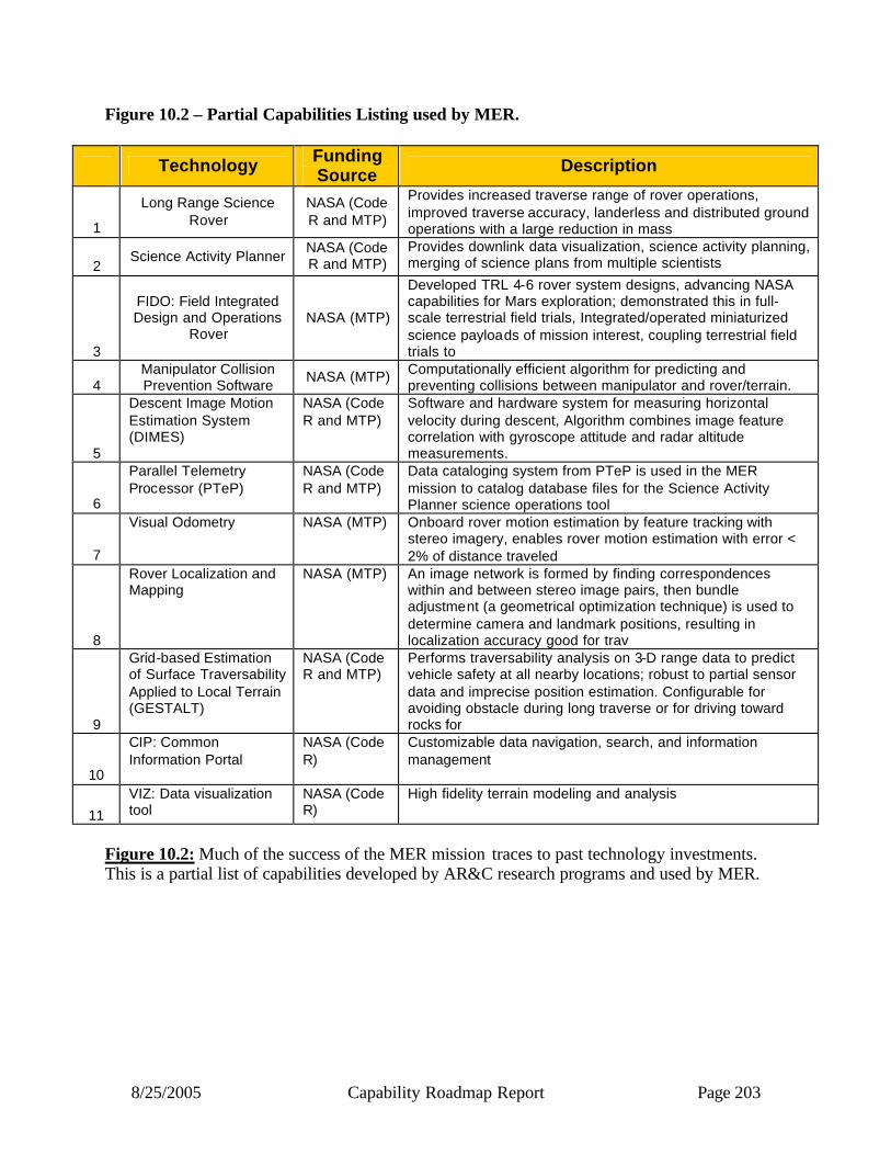
8/25/2005 Capability Roadmap Report Page 203
Figure 10.2 – Partial Capabilities Listing used by MER.
Technology Funding Source Description
1
Long Range Science Rover
NASA (Code R and MTP)
Provides increased traverse range of rover operations, improved traverse accuracy, landerless and distributed ground operations with a large reduction in mass
2 Science Activity Planner
NASA (Code R and MTP)
Provides downlink data visualization, science activity planning, merging of science plans from multiple scientists
3
FIDO: Field Integrated Design and Operations
Rover NASA (MTP)
Developed TRL 4-6 rover system designs, advancing NASA capabilities for Mars exploration; demonstrated this in full-scale terrestrial field trials, Integrated/operated miniaturized science payloads of mission interest, coupling terrestrial field trials to
4 Manipulator Collision Prevention Software
NASA (MTP) Computationally efficient algorithm for predicting and preventing collisions between manipulator and rover/terrain.
5
Descent Image Motion Estimation System (DIMES)
NASA (Code R and MTP)
Software and hardware system for measuring horizontal velocity during descent, Algorithm combines image feature correlation with gyroscope attitude and radar altitude measurements.
6
Parallel Telemetry Processor (PTeP)
NASA (Code R and MTP)
Data cataloging system from PTeP is used in the MER mission to catalog database files for the Science Activity Planner science operations tool
7
Visual Odometry NASA (MTP) Onboard rover motion estimation by feature tracking with stereo imagery, enables rover motion estimation with error < 2% of distance traveled
8
Rover Localization and Mapping
NASA (MTP) An image network is formed by finding correspondences within and between stereo image pairs, then bundle adjustment (a geometrical optimization technique) is used to determine camera and landmark positions, resulting in localization accuracy good for trav
9
Grid-based Estimation of Surface Traversability Applied to Local Terrain (GESTALT)
NASA (Code R and MTP)
Performs traversability analysis on 3-D range data to predict vehicle safety at all nearby locations; robust to partial sensor data and imprecise position estimation. Configurable for avoiding obstacle during long traverse or for driving toward rocks for
10
CIP: Common Information Portal
NASA (Code R)
Customizable data navigation, search, and information management
11
VIZ: Data visualization tool
NASA (Code R)
High fidelity terrain modeling and analysis
Figure 10.2: Much of the success of the MER mission traces to past technology investments. This is a partial list of capabilities developed by AR&C research programs and used by MER.

8/25/2005 Capability Roadmap Report Page 204
10.1.5 Key Capabilities and Status The most important AR&C capabilities are those that either enable new classes of science or exploration missions, or significantly reduce costs and risks across all NASA missions. In keeping with the comments at our NRC review, the “top 10” capability list shown below in Table 10.3 includes capabilities of both types. Capabilities such as crew-centered operations, human-robot collaboration, and autonomous rendezvous and docking are enabling for NASA’s core exploration agenda. Other capabilities such as process control for autonomous drilling, aerobot mobility, and in-space maintenance and construction enable new classes of science missions that may find evidence of past or present life in or beyond the solar system. Finally, capabilities such as automated tools for root-cause analysis and reductions in the error rate per SLOC (source line of code) will significantly reduce costs and risks across all NASA missions. Table 10.3 - Key Capabilities
Capability/Sub-Capability
Mission or Roadmap Enabled
Current State of Practice
Minimum Estimated Development Time
Crew-centered operations
Long-duration lunar and Mars
exploration
For ISS, ground controllers send up 500K commands per year
10 years (including prototyping required for
human rating) Automated tools for root-cause analysis
Long-duration Lunar and Mars
exploration
Limited technology demonstrations on DS1 and EO1
5-8 years
Autonomous Rendezvous and Capture/Docking (including beyond Earth orbit)
Lunar and Mars sample return.
Lunar long duration crewed.
Russian Progress (with ground support). Japanese technology
demo.
5-8 years
Process control for autonomous drilling
Lunar and Mars drilling missions
Terrestrial demonstrations to 2-3 meters depth
6-8 years
Process control for nuclear reactors
Use of nuclear reactors in surface
and deep-space missions
Low-TRL component demonstrations only
6-8 years
Aerial mobility (aerobot)
Venus, Mars, and Titan aerobot
Low-TRL component demonstrations
8-10 years
Human-robotic collaboration
Lunar long duration crewed, and crewed Mars
exploration
Terrestrial demonstrations with limited robotics
8-10 years
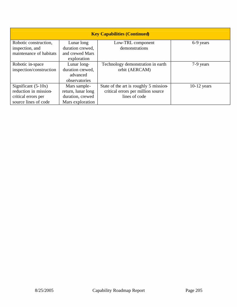
8/25/2005 Capability Roadmap Report Page 205
Key Capabilities (Continued)
Robotic construction, inspection, and maintenance of habitats
Lunar long duration crewed, and crewed Mars
exploration
Low-TRL component demonstrations
6-9 years
Robotic in-space inspection/construction
Lunar long-duration crewed,
advanced observatories
Technology demonstration in earth orbit (AERCAM)
7-9 years
Significant (5-10x) reduction in mission-critical errors per source lines of code
Mars sample-return, lunar long duration, crewed Mars exploration
State of the art is roughly 5 mission-critical errors per million source
lines of code
10-12 years
8/25/2005 Capability Roadmap Report Page 206
10.2 Roadmap Development 10.2.1 Legacy Activities and Roadmap Assumptions The AR&C roadmap inherits directly from the Capability Requirements Analysis and Integration (CRAI) activity (particularly CRAI CBS elements 2.4.1 through 2.4.5). In addition, the roadmap was developed by referencing the following documentation:
• Major recent vision documents: o “The Vision for Space Exploration”, 2004, (Doc NP-2004-01-334-HQ) o “Exploration Systems Interim Strategy”, 2004 o “A Journey to Inspire, Innovate, and Discover”, President’s Commission Report o “The New Age of Exploration: NASA’s Direction for 2005 and Beyond”
• NASA Enterprise Strategy Documents o “The Future of Solar System Exploration, 2003-2013”, NRC Planetary Decadal
Report, 2002 o “Assessment of Mars Science and Mission Priorities”, National Research Council,
2003 o “Scientific Goals, Objectives, Investigations, and Priorities” – MEPAG report on
priorities for Mars exploration o “Mars Exploration Strategy”, Mars Science Program Synthesis Group, 2003 o Solar System Exploration Roadmap, 2003, (Doc JPL 400-1077 5/03)
• Design Reference Missions o Lunar Surface Reference Missions: A Description of Human and Robotic Surface
Activities (NASA/TP 2003-212053) o The Mars Surface Reference Missions: A Description of Human and Robotic
Surface Activities (NASA/TP 2001-209271) o Solar System <update from Cutts>
• ESMD preliminary requirements documents: ESS Technology Requirements RevB, CTS Spirals 1-3 RevB, RLEP Requirements (Sept ’04), CEV ConOps (Sept ’04)
In addition, the AR&C team has had ongoing discussions with the Mars and Solar-System Exploration Strategic Roadmap teams, and several of the capability roadmap teams. 10.2.2 Capability Breakdown Structure
The following is a brief description of the top-level CBS elements:
10.1 Crew-centered and remote operations: Autonomy for command and control of both manned and unmanned science and exploration missions
10.2 Integrated Systems Health Management: design of health management systems, real-time health management, prognostics, and informed logistics.
10.3 Autonomous Vehicle Control: Autonomy for activities where timelines do not allow any ground involvement (e.g., Saturn orbital insertion, Mars EDL).

8/25/2005 Capability Roadmap Report Page 207
10.4 Autonomous Process Control: automation of mission-critical systems that, in terrestrial analog applications, require continuous human monitoring and intervention.
10.5 Robotics for Solar System Exploration: robotic capabilities needed for both unmanned and manned science and explo ration missions on or near lunar and planetary surfaces throughout the solar system
10.6 Robotics for Lunar and Planetary Habitation: robotic capabilities used in preparing for human habitation, maintaining surface habitats, providing support for human sur face operations both in-habitat and in the field, and aiding in the collection of in-situ resources for human habitation.
10.7 Robotics for In-Space Operations: robotic systems needed for assembly, inspection and maintenance, and human-robot interaction in space.
10.8 Robust Software: Tools and techniques supporting the cost effective development, validation, and verification of computing software for all NASA missions.

8/25/2005 Capability Roadmap Report Page 208
Capability Breakdown Structure
Chair: Julia Loftis /GSFC
Crew-CenteredPlanning
10.1.1
10.1.2
AutonomousMission
Operations
Multi -SystemCoordination &Collaboration
10.1.3
Design of HealthManagement
Systems10.2.1
10.2.2
Real-Time SystemHealth
Management
Informed Logistics
10.2.3
Chair: Michel Ingham / JPLCo-Chair: Lorraine Fesq/ JPL
Rendezvousand
Docking10.3.1
10.3.2
Orbit Insertion
Entry, Descent, and Landing
10.3.3
10.3.4
Launch Systems
Chair: James Crawford / ARC
Life Support
10.4.1
10.4.2
ISRU ProcessControl
NuclearReactors
10.4.3
10.4.4
DeepDrilling
Chair: Reid Simmons / CMUCo-Chair: Doug Gage / DARPA (ret.)
Mobilityand Access
10.5.1
10.5.2
Instrument Deployment
Onboard Autonomous
Science
10.5.3
10.5.4
Human-RoboticField Science
10.1 10.2 10.3 10.4 10.5
Crew-Centeredand
Remote Operations
Integrated SystemsHealth
Management
AutonomousVehicle Control
AutonomousProcess Control
Robotics for SolarSystem
Exploration
UAVControl
10.3.5
Plug & Play Controllers
10.4.5
10.4.6
Smart Systems
Human RoboticInteraction
10.5.5
10.0 Autonomous Systems, Robotics,
and Computing Systems
Co-Chair: James Crawford, NASA/ARCCo-Chair: Douglas Gage, DARPA (ret.)Deputy: Paul Schenker, JPL
Human-AutomationInteraction
10.1.4
Multi -ModalInterfaces for Collaborative
Execution10.1.5
Autonomy
Chair: Serder Uckun / ARCCo-Chair: Brian Williams / MIT
Robotics
SiteDevelopment
10.6.1
10.6.2
SiteMaintenance
ISRU
10.6.3
10.6.4
Field Logisticsand Support
10.6
Robotics for Lunarand Planetary
Habitation
Human-RobotInteraction
10.6.5
Chair: Illah Nourbakhsh / ARC
Assembly
10.7.1
10.7.2
Inspection
Maintenance
10.7.3
10.7.4
Human -RobotInteraction
10.7
Robotics for In-Space
Operations
Chair: Ron Diftler / JSC
AutomatedTesting
10.8.1
10.8.2
AnalyticAssurance
Fault tolerance
10.8.3
10.8.4
Certified, automated SW
generation
10.8
ComputingSystems
Maintainability &Reusability
10.8.5
Chair: Mike Lowry / ARCCo-Chair: Mike Evangelist / CMU
Computing
Figure 10.3

8/25/2005 Capability Roadmap Report Page 209
10.2.3 Roadmap Logic This section will describe the logic behind figures 4a and 4b. In the top blue banner of the roadmap, there are those key missions that are pertinent to the roadmap among those derived from the April 15, 2005 interim document delivered by the strategic roadmaps and displayed in the CRM Planning Milestones Chart. The green banner below represents a summary rollup of key capabilities from each of the various capability breakdown structure elements. The peach colored lanes represent the individual top level capability breakdown structure element and the sub-capabilities within this roadmap. The triangles represent the date that the capability is ready to support a given mission, and the diamonds represent decision points.
The roadmap shown in figures 10.4a, through 10.4d are broken up into 2 parts, missions before 2020 and missions post 2020. For science missions prior to 2020, Figure 10.4a shows that AR&C is driven by the Mars Program (particularly Mars Science Laboratory, Mars Sample Return, and Mars Testbed missions), by the robotic lunar exploration programs, by Solar System Exploration (particularly Europa but also by other missions such as Venus Aerobot or comet sample return if those missions are scheduled in this period), and by missions utilizing multiple platforms (such as LISA).
Science missions beyond 2020 show as before, that the Mars and Lunar explorations programs are major drivers. However, Solar System Exploration becomes a more important driver due to the need for surface exploration of Europa and/or Titan (and potentially other missions such as Venus Aerobot). During this period we also expect satellite constellations to become more important for Sun-Earth connection missions. Finally, the need for in-space assembly and maintenance for larger observatories is expected to grow.
Figure 10.4c shows manned exploration missions. Through 2020, two major AR&C drivers are the need to radically reduce the role of the ground in operations and empower the crew to manage operations (this is driven by cost considerations and the need to look ahead to operations beyond the Earth-Moon neighborhood), and the need to enable teams of humans and robots to function together to accomplish missions in-space and on planetary surfaces. Capability deliverables for both drivers are shown in the figures – particularly at the time of the first long duration lunar missions. Other major AR&C capability deliverables include process control for nuclear reactors and decision support for rapid mission abort decisions.
Many of the capability needs for exploration missions beyond 2020 are similar to those for long duration lunar (indeed the requirements for long-duration lunar missions were derived to be those that need to be demonstrated before missions to Mars). New capabilities include in-space assembly, inspection, and maintenance to enable the cost-effective pursuit of Mars missions.
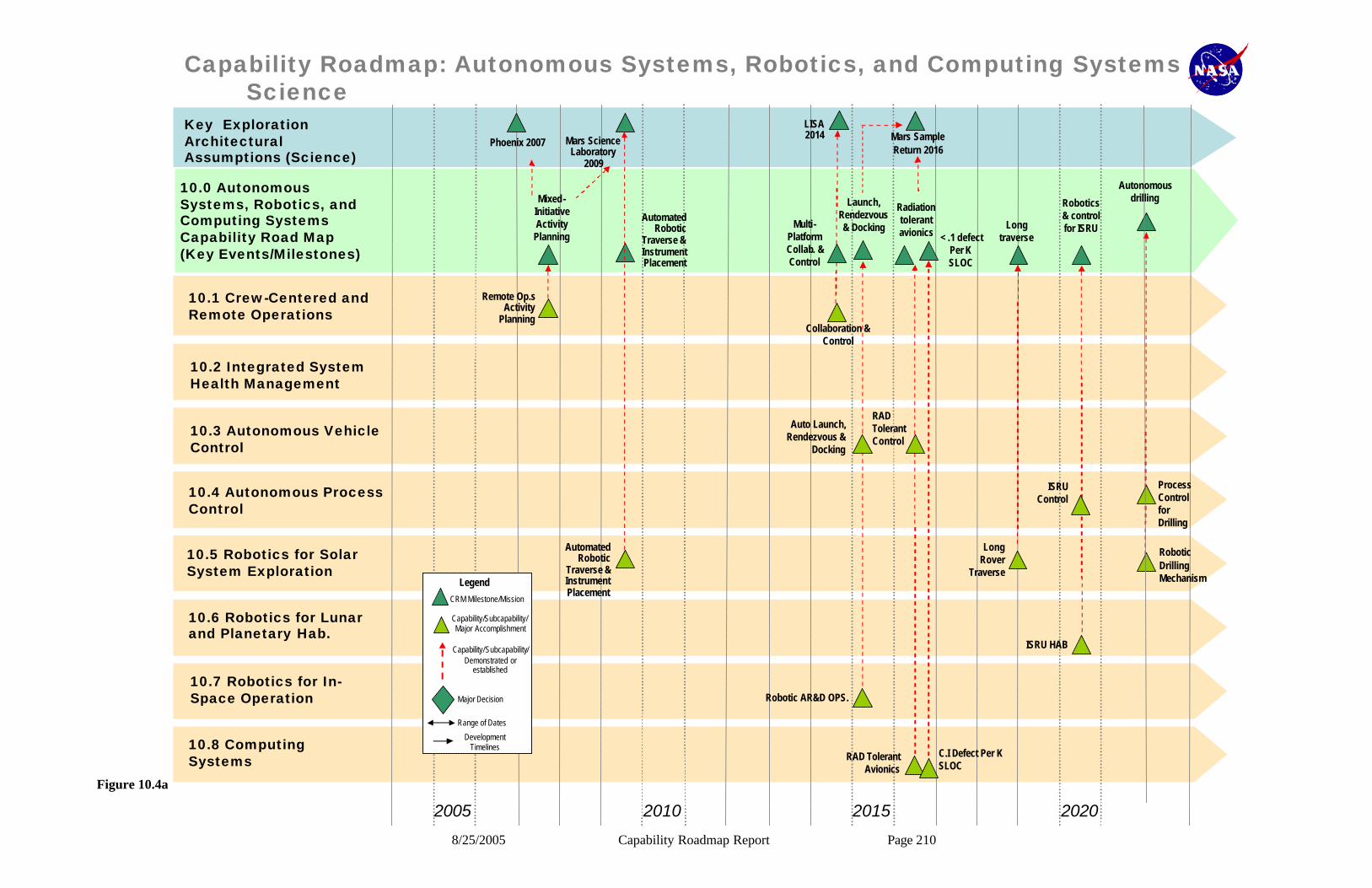
8/25/2005 Capability Roadmap Report Page 210
2005 2010 20202015
Key Exploration Architectural Assumptions (Science)
10.1 Crew-Centered andRemote Operations
10.2 Integrated SystemHealth Management
10.3 Autonomous VehicleControl
10.4 Autonomous ProcessControl
10.5 Robotics for SolarSystem Exploration
10.6 Robotics for Lunar and Planetary Hab.
10.7 Robotics for In-Space Operation
10.8 Computing Systems
10.0 Autonomous Systems, Robotics, and Computing Systems Capability Road Map(Key Events/Milestones)
Capability Roadmap: Autonomous Systems, Robotics, and Computing Systems
LISA 2014
Multi-PlatformCollab. &Control
Mars ScienceLaboratory
2009
Launch, Rendezvous& Docking Long
traverse
Robotics& controlfor ISRU
< .1 defectPer KSLOC
Phoenix 2007
Mixed-InitiativeActivity
Planning
Radiationtolerantavionics
Autonomousdrilling
Mars SampleReturn 2016
Science
Remote Op.sActivity
Planning
Automated Robotic
Traverse & Instrument Placement
Collaboration & Control
Auto Launch, Rendezvous &
Docking
Robotic AR&D OPS.
RAD Tolerant Avionics
C.I Defect Per K SLOC
ISRU HAB
Long Rover
Traverse
RAD Tolerant Control
ISRU Control
Process Control for Drilling
Robotic Drilling Mechanism
Automated Robotic
Traverse & Instrument Placement
Capability/Subcapability/Major Accomplishment
Capability/Subcapability/Demonstrated or
established
CRM Milestone/Mission
Major Decision
Range of Dates
Development Timelines
Legend
Capability/Subcapability/Major Accomplishment
Capability/Subcapability/Demonstrated or
established
CRM Milestone/Mission
Major Decision
Range of Dates
Development Timelines
Legend
Figure 10.4a

8/25/2005 Capability Roadmap Report Page 211
2005 2010 20202015
Key Exploration Architectural Assumptions (Exploration)
10.1 Crew-Centered andRemote Operations
10.2 Integrated SystemHealth Management
10.3 Autonomous VehicleControl
10.4 Autonomous ProcessControl
10.5 Robotics for SolarSystem Exploration
10.6 Robotics for Lunar and Planetary Hab.
10.7 Robotics for In-Space Operation
10.8 Computing Systems
Capability Roadmap: Autonomous Systems, Robotics, and Computing Systems
CEV crewed 2014 Long Duration Lunar 2020Prometheus 2017
Rootcause
analysis
Crewcentered
operations(prototype)
Nuclearreactor
processcontrol
Crewcentered
operations
Humanrobotic
collaboration
Decisionsupport
formission
abort
Process controlfor life support
Process controlfor life support
10.0 Autonomous Systems, Robotics, and Computing Systems Capability Road Map(Key Events/Milestones)
Exploration
Crew Centered Ops
ISHM CEV Prototype
Auto Mission abort Rules
CEV Computing
Decision Support
Nuclear Process Control
Nuclear ISHM
System Root Cause
Analysis
Remote Human /
Robotic Op.s
ISHM Crew Interface
Lunar Surface
Robotics
Habitat Robotics
In-Space Robotics
Lunar Base Computing
systems
Capability/Subcapability /Major Accomplishment
Capability/Subcapability/Demonstrated or
established
CRM Milestone/Mission
Major Decision
Range of Dates
Development Timelines
Legend
Capability/Subcapability /Major Accomplishment
Capability/Subcapability/Demonstrated or
established
CRM Milestone/Mission
Major Decision
Range of Dates
Development Timelines
Legend
Figure 10.4b

8/25/2005 Capability Roadmap Report Page 212
2020 2025 20352030
Key Exploration Architectural Assumptions (Science)
10.1 Crew-Centered andRemote Operations
10.2 Integrated SystemHealth Management
10.3 Autonomous VehicleControl
10.4 Autonomous ProcessControl
10.5 Robotics for SolarSystem Exploration
10.6 Robotics for Lunar and Planetary Hab.
10.7 Robotics for In-Space Operation
10.8 Computing Systems
Capability Roadmap: Autonomous Systems, Robotics, and Computing Systems
Lunarrover 100km
Traverse 2029
MarsAeronomy
2026
TitanAdvanced
2030
Mag Con 2021
L1 Diamond 2023
SAFIR
In-spaceconnecting
Multi-platformCollaboration &
controlAerial
mobility
AerialMobility(highly
Autonomous)Very longtraverse
Comet SampleReturn
2032
SmallBodyEDL
Planet Imager 2034
In-spaceassembly
10.0 Autonomous Systems, Robotics, and Computing Systems Capability Road Map(Key Events/Milestones)
Science
Remote Operations
Auto Control
Remote Operations
Auto Aerial Control
Remote OPS
Robotics Rover
Aerobot
Remote OPS Remote
Operations
Auto EDL Control
Robotic Assembly
Robotic Connections
Capability/Subcapability/Major Accomplishment
Capability/Subcapability/Demonstrated or
established
CRM Milestone/Mission
Major Decision
Range of Dates
Development Timelines
Legend
Capability/Subcapability/Major Accomplishment
Capability/Subcapability/Demonstrated or
established
CRM Milestone/Mission
Major Decision
Range of Dates
Development Timelines
Legend
Figure 10.4c
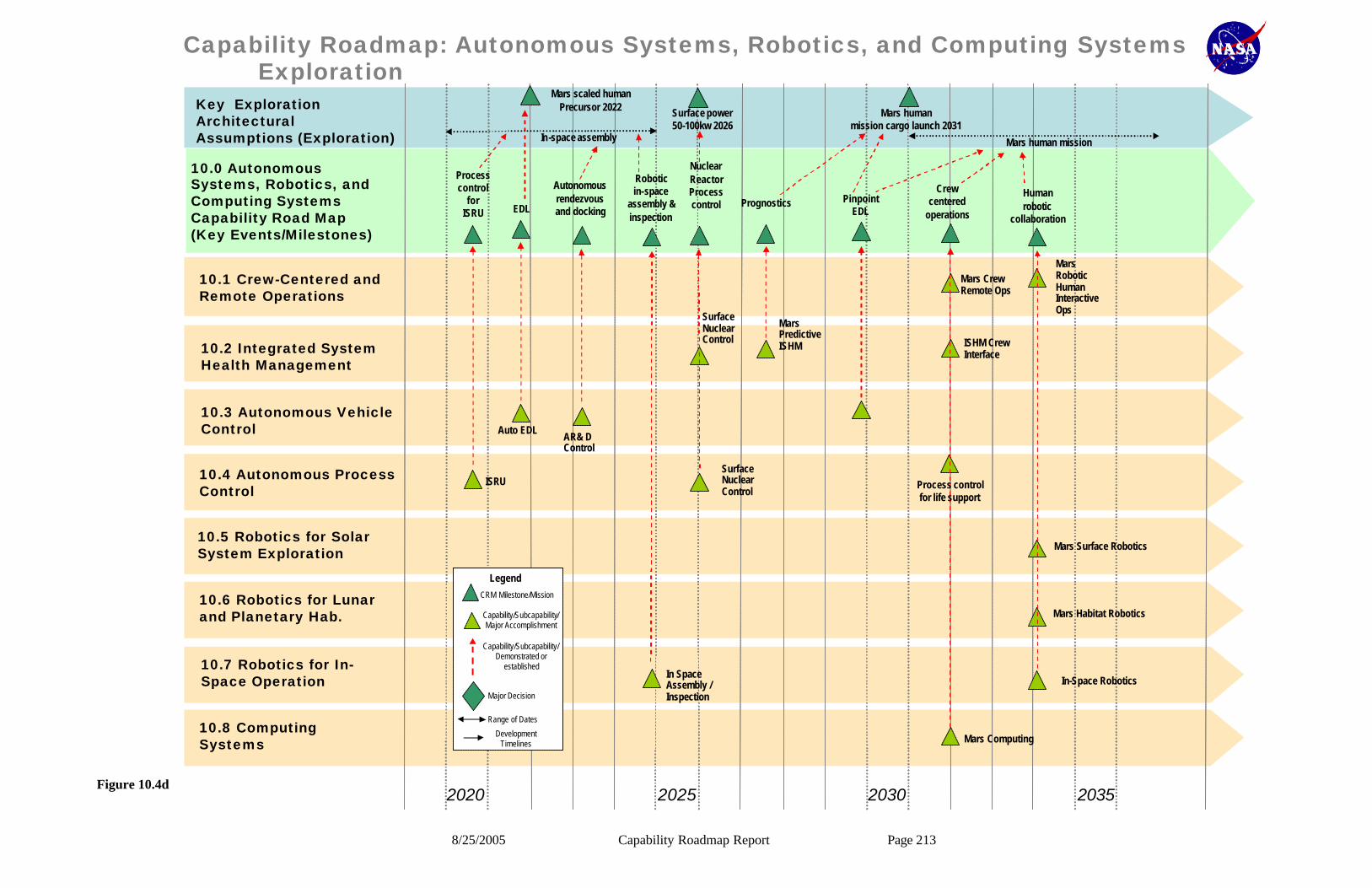
8/25/2005 Capability Roadmap Report Page 213
2020 2025 20352030
Key Exploration Architectural Assumptions (Exploration)
10.1 Crew-Centered andRemote Operations
10.2 Integrated SystemHealth Management
10.3 Autonomous VehicleControl
10.4 Autonomous ProcessControl
10.5 Robotics for SolarSystem Exploration
10.6 Robotics for Lunar and Planetary Hab.
10.7 Robotics for In-Space Operation
10.8 Computing Systems
Capability Roadmap: Autonomous Systems, Robotics, and Computing Systems
Crewcentered
operations
Humanrobotic
collaboration
In-space assembly
Mars humanmission cargo launch 2031
Mars human mission
Roboticin-space
assembly &inspection
PinpointEDL
Prognostics
Autonomousrendezvousand docking
Process controlfor life support
Surface power50-100kw 2026
NuclearReactorProcesscontrol
Mars scaled humanPrecursor 2022
Processcontrol
forISRU EDL
10.0 Autonomous Systems, Robotics, and Computing Systems Capability Road Map(Key Events/Milestones)
Exploration
ISRU
Auto EDLAR& D Control
In Space Assembly / Inspection
Surface Nuclear Control
Surface Nuclear Control
Mars Predictive ISHM ISHM Crew
Interface
Mars Crew Remote Ops
Mars Robotic Human Interactive Ops
Mars Surface Robotics
Mars Habitat Robotics
In-Space Robotics
Mars Computing
Capability/Subcapability/Major Accomplishment
Capability/Subcapability/Demonstrated or
established
CRM Milestone/Mission
Major Decision
Range of Dates
Development Timelines
Legend
Capability/Subcapability/Major Accomplishment
Capability/Subcapability/Demonstrated or
established
CRM Milestone/Mission
Major Decision
Range of Dates
Development Timelines
Legend
Figure 10.4d
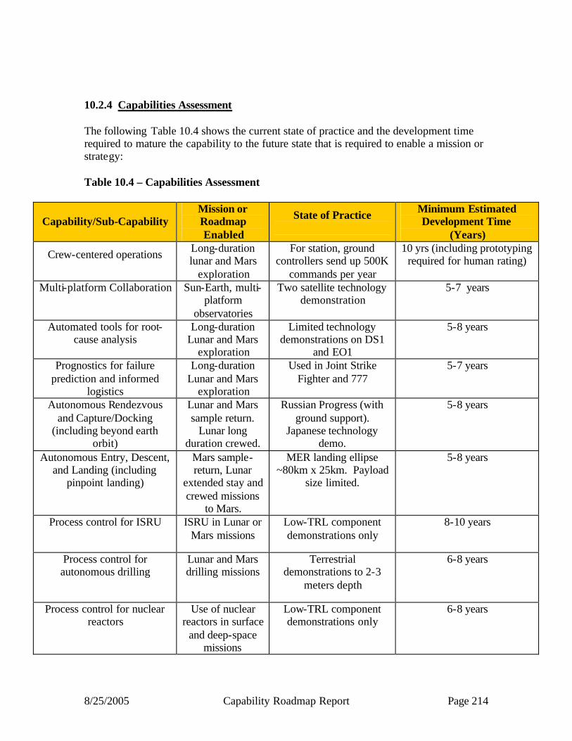
8/25/2005 Capability Roadmap Report Page 214
10.2.4 Capabilities Assessment The following Table 10.4 shows the current state of practice and the development time required to mature the capability to the future state that is required to enable a mission or strategy: Table 10.4 – Capabilities Assessment
Capability/Sub-Capability Mission or Roadmap Enabled
State of Practice
Minimum Estimated Development Time
(Years)
Crew-centered operations
Long-duration lunar and Mars
exploration
For station, ground controllers send up 500K
commands per year
10 yrs (including prototyping required for human rating)
Multi-platform Collaboration Sun-Earth, multi-platform
observatories
Two satellite technology demonstration
5-7 years
Automated tools for root-cause analysis
Long-duration Lunar and Mars
exploration
Limited technology demonstrations on DS1
and EO1
5-8 years
Prognostics for failure prediction and informed
logistics
Long-duration Lunar and Mars
exploration
Used in Joint Strike Fighter and 777
5-7 years
Autonomous Rendezvous and Capture/Docking
(including beyond earth orbit)
Lunar and Mars sample return.
Lunar long duration crewed.
Russian Progress (with ground support).
Japanese technology demo.
5-8 years
Autonomous Entry, Descent, and Landing (including
pinpoint landing)
Mars sample-return, Lunar
extended stay and crewed missions
to Mars.
MER landing ellipse ~80km x 25km. Payload
size limited.
5-8 years
Process control for ISRU ISRU in Lunar or Mars missions
Low-TRL component demonstrations only
8-10 years
Process control for autonomous drilling
Lunar and Mars drilling missions
Terrestrial demonstrations to 2-3
meters depth
6-8 years
Process control for nuclear reactors
Use of nuclear reactors in surface
and deep-space missions
Low-TRL component demonstrations only
6-8 years
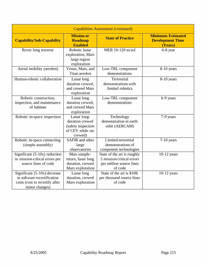
8/25/2005 Capability Roadmap Report Page 215
Capabilities Assessment (continued)
Capability/Sub-Capability Mission or Roadmap Enabled
State of Practice
Minimum Estimated Development Time
(Years) Rover long traverse Robotic lunar
exploration, Mars large region exploration
MER 10-120 m/sol
6-8 year
Aerial mobility (aerobot) Venus, Mars, and Titan aerobot
Low-TRL component demonstrations
8-10 years
Human-robotic collaboration Lunar long duration crewed, and crewed Mars
exploration
Terrestrial demonstrations with
limited robotics
8-10 years
Robotic construction, inspection, and maintenance
of habitats
Lunar long duration crewed, and crewed Mars
exploration
Low-TRL component demonstrations
6-9 years
Robotic in-space inspection Lunar long-duration crewed (safety inspection of CEV while un-
crewed)
Technology demonstration in earth
orbit (AERCAM)
7-9 years
Robotic in-space connecting (simple assembly)
SAFIR and other large
observatories
Limited terrestrial demonstrations of
component technologies
7-10 years
Significant (5-10x) reduction in mission-critical errors per
source lines of code
Mars sample-return, lunar long duration, crewed Mars exploration
State of the art is roughly 5 mission-critical errors per million source lines
of code
10-12 years
Significant (5-10x) decrease in software recertification
costs (cost to recertify after minor changes)
Lunar long duration, crewed Mars exploration
State of the art is $10K per thousand source lines
of code
10-12 years
8/25/2005 Capability Roadmap Report Page 216
10.2.5 Relationship to Other Roadmaps (capability and strategic) In-Space Transportation: AR&C developing process control for nuclear reactors. Integrated Systems Health Monitoring (ISHM) is critical for propulsion systems.
Advanced telescopes and observatories: In-space inspection, maintenance, and connecting/assembly critical for future observatories.
Communication and Navigation: Avionics (10.9 – not completely developed in current roadmap) overlaps heavily with communication and navigation.
Robotic access to planetary surfaces: This roadmap develops much of the hardware required for surface robotics (including rovers and drills). This directly complements the software technology developed in this roadmap.
Human planetary landing systems: Autonomy for EDL is enabling for landing systems.
Human exploration systems and mobility: Human exploration systems require close collaboration with robotics. Also, autonomous operations are required for crew-centered operations.
In-situ resource utilization: This roadmap (AR&C) develops process control for ISRU.
Advanced modeling and simulation: Advanced modeling and simulation is required for validation and verification of autonomous systems.
System-Engineering, Cost/Risk analysis: This roadmap develops capabilities to estimate the costs and risks of software development.
10.3 Summary Autonomous Systems, Robotics, and Computing Systems is heavily cross-cutting. Most capabilities are relevant to multiple missions and mission classes. Some capabilities, such as Integrated Vehicle Health Management, Software Validation and Verification, and Autonomy for Operations, are relevant to virtually all NASA missions. The presence or absence of other “breakthrough” AR&C capabilities, such as autonomy for crew-centered operations, autonomous drilling, aerobots, and robotics for in-space maintenance and assembly, will have broad impacts on multiple strategic roadmaps. One aspect of AR&C that is important to understand is the degree to which the challenges in this area are, or are not, shared by private industry or other government agencies. It is true that DoD, DoE and various areas of private industry are making investments in robotics and computing. However, there are unique aspects of NASA’s requirements that create pacing challenges in AR&C. Generally speaking, these NASA’s pacing challenges trace to three sources: 1. Extremely high dependably requirements for one-of-a-kind systems. DoD and
private industry build new systems. However, they generally build tens to thousands of copies of their systems and single failures are not a disaster. For NASA,
8/25/2005 Capability Roadmap Report Page 217
however, it was critical, for example, that the first Mars rover worked and worked correctly. Since in modern systems hardware failures are generally addressed by fault recovery procedures written in software, these reliability requirements fall particularly hard on software in general and autonomy software in particular.
2. Surface exploration. NASA missions are increasingly moving from orbital surveys to in-situ science. The orbital environment is harsh but generally predictable. The surface environment, however, features rocks, cliffs, sand, wind, clouds, ice, tar, and other unknown hazards. NASA craft must be prepared to fend for themselves for at least the communication latency to earth (which is from 20 minutes to hours). This is challenging for rovers and much more of a challenging for aerobots, cryobots, drills, etc.
3. Challenging manipulation tasks. NASA missions will increasingly involve drilling, in-situ science, life science experiments, ISRU, habitat construction, in-space maintenance and assembly, and other challenging manipulation tasks. As for surface exploration, many of these tasks will involve systems that are dynamic on time scales less than the communication latencies to earth. These requirements create NASA pacing challenges in both autonomy and robotics.
Finally, a word about strategic needs in AR&C. Generally speaking AR&C does not require large and expensive infrastructure. However, it is critical that NASA develop and maintain a community of researchers and developers, in private labs, Universities, and NASA centers, who have a long term commitment to understand and address NASA’s AR&C challenges. This in turn requires that NASA create and maintain a stable and dependable set of funding streams to sustain this community. Major temporal gaps in NASA’s support in these areas have serious long term impacts since research communities disband and talented personnel migrate to other research areas less relevant to NASA’s challenges.

8/25/2005 Capability Roadmap Report Page 218
DRAFT NASA
Capability Road Map (CRM) 11
Transformational Spaceport and Range (SR)
Executive Summary
Chair: Karen Poniatowski, NASA HQ Co-Chair: Jimmey Morrell, (USAF, Ret.)
Co-Chair: Dennis Hilley, OSD/NII Space Programs
Coordinators
Directorate
Michele Gates, NASA SOMD
APIO
Darin Skelly, NASA KSC
Team Members
NASA / FAA
Carole Flores, FAA
Jim Costrell, NASA HQ Jim Heald, NASA KSC
Bob Sackheim, NASA MSFC Bruce Underwood, NASA MSFC
Industry
Tom Maultsby, Consultant
8/25/2005 Capability Roadmap Report Page 219
DRAFT 11 Transformational Spaceport and Range 11.1 General Capability Overview 11.1.1 CAPABILITY DESCRIPTION The Transformational Spaceport and Range (S&R) Capability Roadmap (CRM) focused on an assessment of federal ranges and supporting spaceport infrastructure capabilities to support the Space Exploration Vision, while examining the potential of state and commercial endeavors. Given the inherent vested interest in any investments in Range or Spaceport assets/capabilities, other Government agencies (USAF and FAA) were included as members of this Committee. While the goal of this Roadmap was to identify capabilities required to implement the Space Exploration Vision, the S&R CRM Committee assured that the discussion and recommendations were kept in context with non-NASA needs, since DoD owns/operates the Eastern and Western Ranges, which are also used by commercial operators. The S&R CRM Committee defined the term “Spaceport” as the collection of customer services/support at the launch site. Examples of these capabilities include, but are not limited to, launch vehicle and spacecraft processing, logistics, communications, launch countdown operations/contingency planning, and landing/recovery operations. Similarly, the Team defined the term “Range” as those assets and resources required to ensure public safety from hazardous operations. Federal Ranges encompass a mix of Range and Spaceport functionality. The S&R committee determined that the assessment should be considered in two specific time periods; 2005-2015 and 2016-2030. The intent was to ensure that the current capabilities could meet the expected needs of the Space Exploration Initiatives in the early years, recognizing all other activities manifested at the launch sites. With respect to the 2005-2015 period, this examination also considered actions or improvements that could provide transformational capabilities on the ranges/spaceports in this period, even if the current capabilities were able to meet the forecast requirements of the period, that they should receive support and funding. The second period, 2016-2030, was focused on examining potential decision points to ensure adequate lead times for the proper technology investments or systems capabilities for out-year and more difficult exploration requirements. The recommendations and findings are noted in the body of the report. The new National Space Transportation Policy (NSTP) was signed by the President in December 2004. This directive placed specific emphasis on Federal space launch bases/ranges and requires NASA and the DoD to work together to ensure the ranges are operated in a manner so as to accommodate all users. The NSTP also calls for transitioning range capabilities to“predominantly space-based range architecture”. NASA and the DOD utilized the Spaceport/Range Capability Roadmap activities to address the NSTP direction as the National Implementation Strategy is developed. Space-based systems, such as NASA’s Tracking and Data Relay Satellite System (TDRSS) for communications and telemetry and
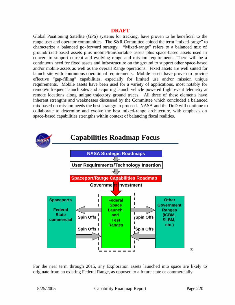
8/25/2005 Capability Roadmap Report Page 220
DRAFT Global Positioning Satellite (GPS) systems for tracking, have proven to be beneficial to the range user and operator communities. The S&R Committee coined the term “mixed-range” to characterize a balanced go-forward strategy. “Mixed-range” refers to a balanced mix of ground/fixed-based assets plus mobile/transportable assets plus space-based assets used in concert to support current and evolving range and mission requirements. There will be a continuous need for fixed assets and infrastructure on the ground to support other space-based and/or mobile assets as well as the overall Range operations. Fixed assets are well suited for launch site with continuous operational requirements. Mobile assets have proven to provide effective “gap-filling” capabilities, especially for limited use and/or mission unique requirements. Mobile assets have been used for a variety of applications, most notably for remote/infrequent launch sites and acquiring launch vehicle powered flight event telemetry at remote locations along unique trajectory ground traces. All three of these elements have inherent strengths and weaknesses discussed by the Committee which concluded a balanced mix based on mission needs the best strategy to proceed. NASA and the DoD will continue to collaborate to determine and evolve the best mixed-range architecture, with emphasis on space-based capabilities strengths within context of balancing fiscal realities.
50
Capabilities Roadmap Focus
FederalSpace
Launch and Test
Ranges
OtherGovernment
Ranges(ICBM, SLBM,
etc.)
Spaceports
FederalState
commercial Spin Offs Spin Offs
Spin Offs Spin Offs
Spaceport/Range Capabilities Roadmap
Government Investment
User Requirements/Technology Insertion
NASA Strategic Roadmaps
For the near term through 2015, any Exploration assets launched into space are likely to originate from an existing Federal Range, as opposed to a future state or commercially

8/25/2005 Capability Roadmap Report Page 221
DRAFT managed site. In the long term, post 2015, this paradigm may change as requirements are better defined and transportation capabilities developed to meet these TBD requirements. As such, spaceport and range assets are inherent enablers for launching space vehicles. Most of the technologies discussed by the S&R SRM Committee were targeted at improving existing capabilities’ effectiveness (e.g., higher data rates, safer operations), and/or improved flexibility (e.g., accommodate higher launch frequency, enable parallel operations, reduce downtime/delays), and/or cost reduction (e.g., lower life cycle costs, reduce maintenance). Typically, capabilities must be driven by mission/vehicle requirements. As NASA Space Exploration transportation requirements become defined, specific capabilities can be identified. It is also recognized that in some cases a technology push may be warranted to provide long term capabilities. The S&R CRM Committee noted in the near term one such option, a “test-range” capability (see recommendation #3), and recommend that this be examined for the period beyond 2015 as the programs begin to be better defined.
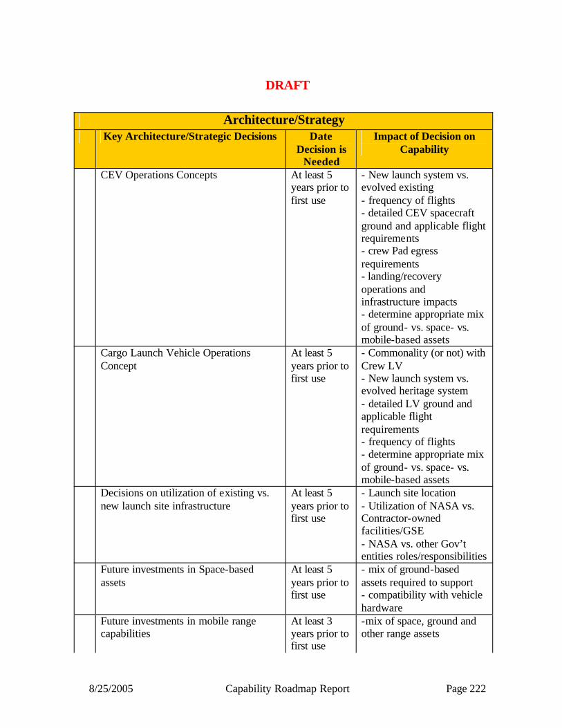
8/25/2005 Capability Roadmap Report Page 222
DRAFT
Architecture/Strategy Key Architecture/Strategic Decisions Date
Decision is Needed
Impact of Decision on Capability
CEV Operations Concepts
At least 5 years prior to first use
- New launch system vs. evolved existing - frequency of flights - detailed CEV spacecraft ground and applicable flight requirements - crew Pad egress requirements - landing/recovery operations and infrastructure impacts - determine appropriate mix of ground- vs. space- vs. mobile-based assets
Cargo Launch Vehicle Operations Concept
At least 5 years prior to first use
- Commonality (or not) with Crew LV - New launch system vs. evolved heritage system - detailed LV ground and applicable flight requirements - frequency of flights - determine appropriate mix of ground- vs. space- vs. mobile-based assets
Decisions on utilization of existing vs. new launch site infrastructure
At least 5 years prior to first use
- Launch site location - Utilization of NASA vs. Contractor-owned facilities/GSE - NASA vs. other Gov’t entities roles/responsibilities
Future investments in Space-based assets
At least 5 years prior to first use
- mix of ground-based assets required to support - compatibility with vehicle hardware
Future investments in mobile range capabilities
At least 3 years prior to first use
-mix of space, ground and other range assets

8/25/2005 Capability Roadmap Report Page 223
DRAFT
KEY SPACEPORT/RANGE CAPABILITIES Spaceport and Customer Services:
1. Communications, command and control for Constellation 2. Improved commodities servicing next generation Personal Protective Equipment
(PPE) (e.g. Advanced Self-Contained Atmosphere Protective Ensemble (SCAPE)) 3. Pad crew access 4. Human-related systems checkout and servicing 5. Egress and emergency systems 6. Launch infrastructure and systems for new vehicles 7. Rapid turnaround of launch infrastructure 8. Weather modeling for increased resolution and improved prediction capability
Range and Publis Safety:
1. Improved metric tracking for ground systems 2. Enhanced flight termination system 3. Improved broadband communications system 4. Space-based telemetry and range safety 5. Readily deployable mobile range assets 6. Improved surveillance for sea traffic in launch impact zone
Major Technical Challenges (Top 10 Maximum for Table) 2006-2010 The Committee assessed the existing capabilities/technology to be adequate for launch requirements identified at this time. No major technological challenges have been identified as a result of this Roadmap effort. Opportunities for increasing efficiencies and improved range turnaround are possible dependent on funding availability and launch vehicle operations concepts. ( Heritage vs. evolved vs. new systems) 2010 - 2015 The Committee assessed the existing capabilities/technology to be adequate for potential launch requirements through 2015. Decisions to utilize a shuttle derived launch concept warrant further assessment as do CEV launch site requirements. No major technological challenges have been identified as a result of this Roadmap effort. Requirements for processing, handling, launch of new nuclear propulsion systems requires identification early to enable requisite facility development. 2020 and Beyond
Technical challenges forward will depend on factors such as CEV and Cargo LV operations concepts and resulting vehicle/ops requirements; NASA and non-NASA investments in related technologies; and lead-time (or lack thereof) to implement new technology. Role of state and commercial spaceports may also be revisited as requirements defined.

8/25/2005 Capability Roadmap Report Page 224
DRAFT Institutional:
1. Service based communications 2. Consolidation of communication systems 3. Data access & security
11.2 Roadmap Development 11.2.1 REFERENCE RELEVANT LEGACY ACTIVITIES The Committee initiated the Roadmap development effort by examining existing capabilities and plans by various federal (both from internal and external to NASA) and commercial entities. These participants offered reference material for the Committee to consider for use. The following items were primary sources of data:
1. National Space Transportation Policy, dated December 2004 2. NASA and DoD Launch Manifests 3. Advanced Range Technology Working Group (ARTWG) Report dated March 2004 4. Advanced Spaceport Technology Working Group (ARTWG) Report dated September
2003 5. APIO Design Reference missions 6. Informational briefings from various Government and industry representatives
11.2.2 TOP-LEVEL ARCHITECTURAL ASSUMPTIONS ANDAPPLICATIONS Due to the inherent “support” and “enabling” functionality that the Spaceport and Range capabilities perform, maintaining existing and introduction of proposed technologies should primarily be tied to mission/vehicle requirements, especially in times of constrained budgets. Prior to and during this Roadmap effort, the fidelity of the existing Space Exploration requirements relevant to this effort was inadequate to allow for gap analysis, identification of technologies to fill the gaps, or prioritization of technology investments. The Committee was able to make some top- level assumptions and identify some common user themes, upon which the identification of some generic capabilities and recommendations are based. The only Strategic Roadmap (SRM) with significant influence on the S&R CRM is the Transportation SRM. Any other SRMs with driving requirements would likely drive Transportation requirements, which would be the direct connection to the S&R CRM. As of Apr 15, the Transportation SRM Interim Report was not available, so the S&R CRM Committee could not consider it. The following is a summary of key assumptions by the S&R CRM Committee:
• Most Space Exploration activities assumed to require launch and processing support from federal facilities in Florida for CEV, heavy lift and intermediate and large class launch requirements
• Space Exploration requirements for the ranges involve: – Responsiveness (rapid turnaround) from tests, rehearsals or launches

8/25/2005 Capability Roadmap Report Page 225
– Elimination of operational constraints imposed by Range such as launch trajectories which must be flown to permit proper range equipment operations and safety restrictions where appropriate improvements could be made through better modeling or equipment capability
– Improved operational planning capabilities and approvals to support new missions. These include planning and support systems, modeling, dispersions, break up analysis, and nuclear power systems
• Anticipate the USAF will continue to provide the basic capabilities for common user requirements and range/public safety at Eastern and Western Ranges for the foreseeable future and will provide the funding for common user needs
– Includes command and control, scheduling, analyses, optics, telemetry, and communications
• Assume NASA will continue to provide spaceport customer services and institutional support at KSC and Wallops Flight Facility
• NASA will fund for mission specific capabilities required to support the Space Exploration Initiative
In addition to these assumptions, the Committee examined NASA, DoD, and commercial launch manifests to identify any potential concerns with Spaceport or Range capacity issues. The APIO provided a multitude of data regarding future space missions with varying degrees of pedigree. The Committee determined that the existing manifest projections in the traffic model, as seen below, enveloped the APIO-provided design reference missions.
Transportation Requirements
2005 2010 2015 2020 20302025
Heavy Lift Cargo
CEV LV
Space Shuttle
EELV-class (AV/DIV)
Medium-class
Small (Pegasus/Taurus)
HLLV DDT&E
RTF
STS Flights
Assy/Util Utilization
ISS
Assembly Complete
ISS Re-supplyISS Re-supply
CREW FLIGHTS
TDRS-FOScience Missions (e.g., Mars, New Frontiers, TPF,etc.) – 1-2 missions/yr
Science Missions (e.g., Mars, MIDEX, Discovery, EOS, ,etc.) – 3-5 missions/yrLunar Robotic Precursor Missions – 1 missions/yr
Science Missions (e.g., SMEX, NMP, ESSP ,etc.) – 1 mission/yr
Final STS Flight
ISS Operations Complete
2010
2010 2016
First CEV
~2010 2014 Cargo LVTest Flt
~2017
Cargo LV1st Mission
Legend:Science ReqmtsExploration ReqmtsSpace Ops Reqmts
Legend:Science ReqmtsExploration ReqmtsSpace Ops Reqmts
DRAFT

8/25/2005 Capability Roadmap Report Page 226
CAPABILITY BREAKDOWN STRUCTURE (see Appendix A) The S&R CRM Committee divided the key Spaceport and Range Capabilities into a Capability Breakdown Structure (see Appendix A), as prescribed by APIO. The capabilities fell into three logical areas “Spaceport and Customer Services”, “Range and Public Safety”, and “Institutional”. Each of these three areas was sub-divided into one level lower detail. The Committee determined any lower subdividing of the CBS would be premature and was not warranted, given the lack of fidelity of Exploration requirements. The “Spaceport and Customer Services” box contains primarily functionality that is unique to the Spaceport/Range user(s). Some of these capabilities may service multiple customers and others are likely to be single use. The “Range and Public Safety” category addresses the core functionality of the Range, i.e., Public Safety. This function was subdivided into three natural areas, consistent with a mixed-range architecture; Ground-based, Space-based, and Mobile-based. The “Institutional” area covers those cross-cutting functions/capabilities that may support the “Spaceport” and/or “Range” functions.
Manifest Projections
0
5
10
15
20
25
30
35
40
CY05 CY06 CY07 CY08 CY09 CY10 CY11 CY12 CY13 CY14 CY15 CY16 CY17 CY18 CY19 CY20 CY21 CY22 CY23 CY24 CY25
An
nu
al N
um
ber
of L
aun
ches
National Mission Model
Total Launches w/ Exploration assumingSaturn-V class Heavy Lift
Total Launches w/ Exploration assumingEELV-class Heavy Lift
Dip in Medium Lift Manifest
Space Shuttle Phase-out ISS Phase-out
First Crewed Lunar Missions
DRAFT

8/25/2005 Capability Roadmap Report Page 227
DRAFT
SPACEPORT/RANGE CAPABILITY ROLL-UP (see Appendix B) The S&R capabilities are not influenced by an “Exploration” vs. “Science”-based distinction , rather they are affected by overall national demand which combines known/potential civil requirements with projected national security and commercial demand.. The primary drivers of S&R capabilities are mission architecture, operation concepts, and resulting detailed vehicle requirements. While Exploration or Science requirements may drive certain vehicle requirements, it will be the vehicle and associated operational requirements that will directly influence the needed S&R capabilities. Since the architectures, operations concepts, and vehicle requirement are not yet available, these mapping charts did not add much value to the process. Consistent with the CBS, the Committee attempted to tie some generic S&R capabilities to some notional CEV milestones. 11.2.3 RELATIONSHIP TO OTHER CAPABILITY ROADMAPS The most obvious and inherent relationship to the S&R CRM is with the Communications and Navigation CRM. Due to the inherent interface associated with Space-based assets, the S&R CRM Committee membership included a representative from NASA Space Communications office, and many S&R discussions included members from the Communications and Navigation CRM team. As requested by APIO, the Committee also discussed potential relationships with other CRMs. These relationships were not pursued in Phase 1 (i.e., prior to the NRC Review), but were in the plan for Phase 2 efforts. In addition, there were a few areas where the relationship was undetermined and the Committee defined as “under review”. Further definition of these areas in question was also in the plan for Phase 2. 11.3 Summary The S&R CRM Committee acknowledged a need for higher fidelity vehicle requirements and /or defined operational concepts as a precondition to a useful assessment to identify requirements based capability gaps, specific technologies or development of any type of specific investment strategies. There are a wealth of unprioritized technologies that might be employed to enhance spaceport and range operations, however a cost benefit analysis awaits better requirement definition. The S&R capabilities are inherently supporting enablers and are therefore, highly dependent on the operations to which they serve. However, the Committee was able to define the context within which S&R capabilities decisions should be made. Based on the collection of expertise and past experience, the Committee was also able to define some common themes and observations as well as some recommendation, which are noted below. OBSERVATIONS The following are overarching observations : • The Transformational Spaceport and Range Capability Roadmap assessed potential
implications of emerging exploration requirements on the national capability which is different from other more NASA focused capability roadmaps, in that:
– NASA is one of many users of an existing capability

8/25/2005 Capability Roadmap Report Page 228
– There is a broad diversity of current and potential providers of the capability: federal, state, commercial
– NASA requirements are in various stages of identification and development – NASA Space Exploration related requirements may become a driver for new
technology but those requirements are not yet defined or matured – Funding for these capabilities is tied at least in part to other agencies programs
and budgets • Key task was to identify NASA- unique requirements and any new technology that might
be warranted to meet the Space Exploration Vision – CEV requirements for human transport: Under definition – Cargo requirements for heavy lift transportation: Trade studies considering
evolution of existing shuttle and expendable systems as well as clean sheet approaches under review
– Robotic requirements: e.g., Prometheus requirements under trade study and definition
– Handling of future nuclear power source equipment: Pending requirements definition
• Spaceport Roadmap will be driven by other strategic and capability roadmaps – This roadmap’s major output at this stage in the Space Exploration Vision
definition will be a statement of capabilities and identification of potential paths for future technology investments
• This is a continuous process and will need to be revisited as the Space Exploration requirements affecting public safety and customer needs at the launch site(s) evolve and mature
The following are observations in the area of customer support/satisfaction: – All Spaceports/Ranges have both common and unique needs as a result of their individual
missions and customer base – Investments should be balanced on common spaceport and range user needs as
well as those carrying the highest national priority – Improvement in turnaround times from test, development and launch activities should be
an area for continual improvement – Infrastructure: balance between sustaining current capability and new capability – Balance between resources constraints (people/funding) vs. technology solutions
– Space-based communications capability should assume need for larger data volumes (e.g., power, antennas, etc.)
– Improved range and spaceport planning and scheduling capabilities should be implemented as part of continual improvement efforts
– Consistent with National Space Transportation Policy, all operators/users should seek to maximize use of commercial goods and services
– e.g. satellite processing and general storage and support activities – Reduced Spaceport and Range operations costs will continue to be a noble goal The following are observations in the area of public safety: – Models should be improved and true independent IV&V should be pursued
• Weather prediction and safety calculations for blast and toxic
DRAFT
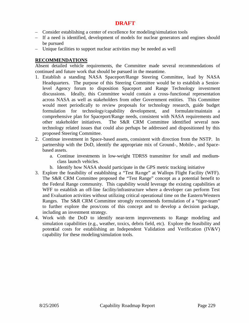
8/25/2005 Capability Roadmap Report Page 229
– Consider establishing a center of excellence for modeling/simulation tools – If a need is identified, development of models for nuclear generators and engines should
be pursued – Unique facilities to support nuclear activities may be needed as well RECOMMENDATIONS Absent detailed vehicle requirements, the Committee made several recommendations of continued and future work that should be pursued in the meantime. 1. Establish a standing NASA Spaceport/Range Steering Committee, lead by NASA
Headquarters. The purpose of this Steering Committee would be to establish a Senior-level Agency forum to disposition Spaceport and Range Technology investment discussions. Ideally, this Committee would contain a cross-functional representation across NASA as well as stakeholders from other Government entities. This Committee would meet periodically to review proposals for technology research, guide budget formulation for technology/capability development, and formulate/maintain a comprehensive plan for Spaceport/Range needs, consistent with NASA requirements and other stakeholder initiatives. The S&R CRM Committee identified several non-technology related issues that could also perhaps be addressed and dispositioned by this proposed Steering Committee.
2. Continue investment in Space-based assets, consistent with direction from the NSTP. In partnership with the DoD, identify the appropriate mix of Ground-, Mobile-, and Space-based assets.
a. Continue investments in low-weight TDRSS transmitter for small and medium-class launch vehicles.
b. Identify how NASA should participate in the GPS metric tracking initiative 3. Explore the feasibility of establishing a “Test Range” at Wallops Flight Facility (WFF).
The S&R CRM Committee proposed the “Test Range” concept as a potential benefit to the Federal Range community. This capability would leverage the existing capabilities at WFF to establish an off- line facility/infrastructure where a developer can perform Test and Evaluation activities without utilizing critical operational time on the Eastern/Western Ranges. The S&R CRM Committee strongly recommends formulation of a “tiger-team” to further explore the pros/cons of this concept and to develop a decision package, including an investment strategy.
4. Work with the DoD to identify near-term improvements to Range modeling and simulation capabilities (e.g., weather, toxics, debris field, etc). Explore the feasibility and potential costs for establishing an Independent Validation and Verification (IV&V) capability for these modeling/simulation tools.
DRAFT
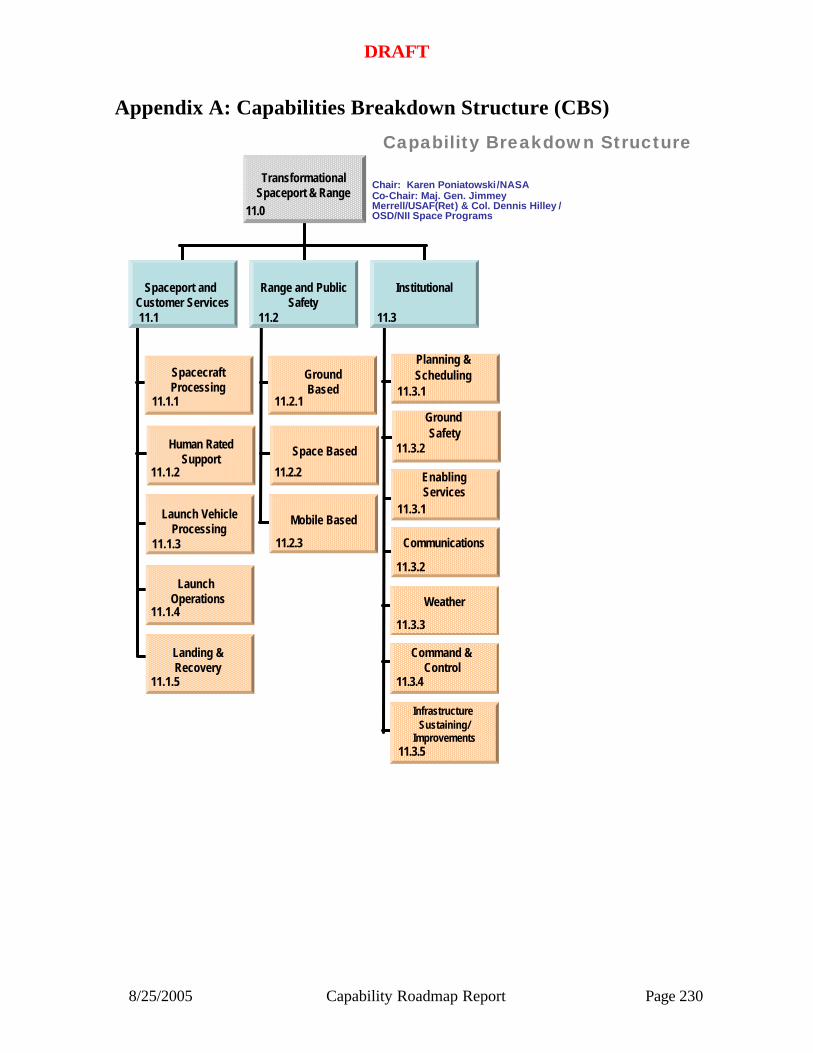
8/25/2005 Capability Roadmap Report Page 230
Appendix A: Capabilities Breakdown Structure (CBS)
Capability Breakdown Structure
SpacecraftProcessing
11.1.1
11.1.2
Human RatedSupport
Launch VehicleProcessing
11.1.3
11.1.4
Launch Operations
GroundBased
11.2.1
11.2.2
Space Based
Mobile Based
11.2.3
Planning &Scheduling
11.3.1
11.3.2
Ground Safety
EnablingServices
11.3.1
11.3.2
Communications
11.1 11.2 11.3
Spaceport and Customer Services
Range and PublicSafety
Institutional
Weather
11.3.3
11.3.4
Command & Control
TransformationalSpaceport & Range
11.1.5
Landing &Recovery
11.3.5
Infrastructure Sustaining/
Improvements
11.0
Chair: Karen Poniatowski/NASACo-Chair: Maj. Gen. JimmeyMerrell/USAF(Ret) & Col. Dennis Hilley / OSD/NII Space Programs
DRAFT

8/25/2005 Capability Roadmap Report Page 231
Appendix B: Top Level Capability Roadmap Rollup (2005-2015)
Capability Roadmap: Transformational Spaceport & Range
11.2 Range & Public Safety
10.3 Institutional
In-Space Transportation Capability Road Map(Key Events/Milestones)
2005 2010 2015
Key Exploration Architectural Assumptions
2008 Lunar Recon. Orbiter Mission
2010 2nd Mission Lunar Robotic Lander
CLV First Flight
2011CEV UncrewedTest Flight
2014 CEV CrewedFlight
CLV SRR
CEV SRR CEV PDR
CEV UncrewedORR
CLV Delivery
CEV Crewed ORR
11.1 Spaceport/Customer Services
Integrated space based capabilities for range and uncrewedCEV Design
SpaceportProcessing
Human Rated Support Launch Vehicle Processing Launch Operations
Landing &Recovery
STARS, GPS, Metric Tracking
Space based range capabilities for safety systems GPS metric systems
Service based commConsolidation of comm SystemsData access & Security
Capability/Subcapability/Major Accomplishment
Capability/Subcapability/Demonstrated or
established
CRM Milestone/Mission
Major Decision
Range of Dates
Development Timelines
Legend
Capability/Subcapability/Major Accomplishment
Capability/Subcapability/Demonstrated or
established
CRM Milestone/Mission
Major Decision
Range of Dates
Development Timelines
Legend
DRAFT

8/25/2005 Capability Roadmap Report Page 232
NASA
Capability Road Map (CRM) 12
Science Instruments and Sensors
Executive Summary
Chair: Richard Barney, NASA GSFC Co-Chair: Maria Zuber, MIT
Deputy Chair: Juan Rivera, NASA GSFC
Coordinators
Directorate
Harley Thronson, NASA SMD Giulio Varsi, NASA SMD
APIO
Perry Bankston, NASA JPL
Team Members
NASA / JPL
Brian Ramsey, NASA MSFC Bruce Spiering, NASA SSC Soren Madsen, NASA JPL
Craig McCreight, NASA ARC Tim Krabach, NASA JPL
Azita Valinia, NASA GSFC Paul Mahaffy, NASA GSFC
Consultants
David Glackin, Aerospace Corp.
Richard McEntire, JHU/ APL Shyam Bajpai, NOAA
Lee Rickard, Naval Research Laboratory
Academia
Chris Ruf, University of Michigan Steve Ackerman, University of Wisconsin
Suzanne Staggs, Princeton
Industry
Ron Polidan, Northrup Grumman Rich Dissly, Ball Aerospace
David Chenette, Lockheed Martin
Technical Experts
Carl Stahle, NASA GSFC Amy Walton NASA ESTO
Louis Barbier, NASA GSFC Thomas Black, NRO

8/25/2005 Capability Roadmap Report Page 233
12 Science Instruments and Sensors (Roadmap 12) 12.1 General Capability Overview 12.1.1 Capability Description The Science Instruments and Sensors (SIS) roadmap includes capabilities associated with the collection, detection, calibration, conversion, and processing of scientific data required to answer compelling science questions driven by the Vision for Space Exploration and The New Age of Exploration (NASA’s Direction for 2005 & Beyond). Science Instruments and Sensors is a broad and diverse rubric with many enabling science measurement challenges. This roadmap is the result of a careful review and analysis of studies conducted by the National Academy of Sciences and by NASA (see Appendix) and of the extensive experience of the team members in scientific space instrumentation. The Science Instrument and Sensor roadmap is organized into capabilities and sub-capabilities corresponding to the measurement wavelength range or specialized function. The six top- level capabilities are listed below:
• Microwave Instruments and Sensors • Multi-Spectral Imaging / Spectroscopy (Vis-IR-FIR) • Multi-Spectral Sensing (UV-Gamma) • Laser / LIDAR Remote Sensing • Direct Sensing of Particles, Fields, and Waves • In Situ Instrumentation
The capability breakdown structure (Figure 12.2) was established to define the sub-capabilities and integrated technologies required to meet instrument or sensor performance criteria. For each capability, the roadmap shows driving design reference missions, science measurements, capability/technology gaps, and a description of the developments (including alternate paths and options) required to advance the capability or technology to spaceflight. Because of the requirement to develop both strategic and capability roadmaps in parallel, it was not possible to prioritize capability development on the basis of the highest-ranked scientific strategies. Thus, the emphasis was placed on identifying science instrument and sensor capabilities that would enable multiple design reference missions (i.e. those having crosscutting applications ). 12.1.2 Benefits The Vision for Space Exploration cannot be achieved without the development of new science instruments and sensors capabilities. These capabilities are necessary for the collection and processing of scientific data, either to answer compelling science questions (e.g, How does life begin?) or to provide crucial knowledge to enable an exploration mission (e.g. remote surveys of Martian geology to identify optimal landing sites). Several of these capabilities are also required to support human missions, through measurements of the safety of the environment and its suitability for human operations.

8/25/2005 Capability Roadmap Report Page 234
Critical science instrument and sensor capabilities were also found to have crosscutting applications in several other capability roadmaps. For example, sensors developed for science applications can also be used for subsur face and atmospheric reconnaissance of planetary surfaces, a priority of the Robotic Access to Planetary Surfaces roadmap (CRM #6). Large format focal planes required by future IR, UV, X-Ray and Gamma Ray instruments can provide critical feedback detection for active wave-front control systems required by the Advanced Telescope and Observatories roadmap (CRM #4).
12.1.3 Key Architecture / Strategic Decisions
Architectural and strategic decisions on the implementation of the Vision will guide the instrument and sensor development. Table 12.1 highlights those that are most important for this roadmap. The order does not indicate prioritization. Each strategic decision includes a description of the needed capability development. The decisions are driven by three primary factors: a) potential scientific discoveries, b) evolving programmatic emphasis, or c) the demonstration of technical feasibility. Dates are consistent with the strategic mission set shown in Table 12.4.
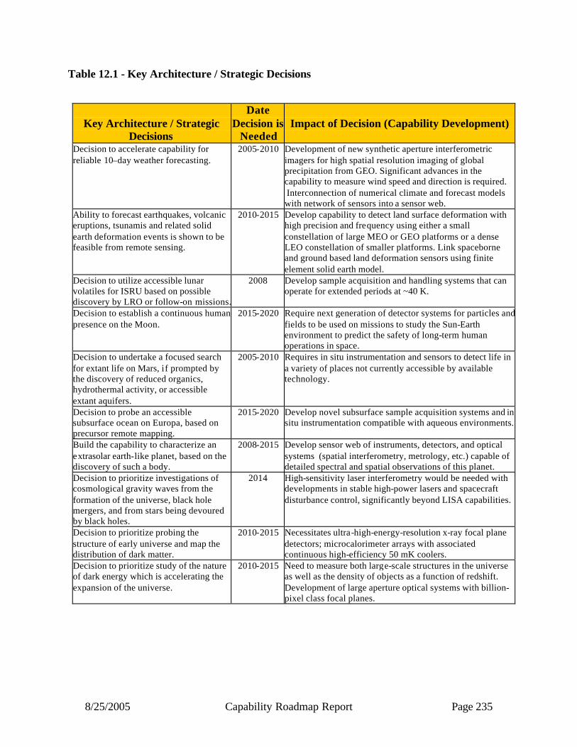
8/25/2005 Capability Roadmap Report Page 235
Table 12.1 - Key Architecture / Strategic Decisions
Key Architecture / Strategic
Decisions
Date Decision is
Needed
Impact of Decision (Capability Development)
Decision to accelerate capability for reliable 10–day weather forecasting.
2005-2010 Development of new synthetic aperture interferometric imagers for high spatial resolution imaging of global precipitation from GEO. Significant advances in the capability to measure wind speed and direction is required. Interconnection of numerical climate and forecast models with network of sensors into a sensor web.
Ability to forecast earthquakes, volcanic eruptions, tsunamis and related solid earth deformation events is shown to be feasible from remote sensing.
2010-2015 Develop capability to detect land surface deformation with high precision and frequency using either a small constellation of large MEO or GEO platforms or a dense LEO constellation of smaller platforms. Link spaceborne and ground based land deformation sensors using finite element solid earth model.
Decision to utilize accessible lunar volatiles for ISRU based on possible discovery by LRO or follow-on missions.
2008 Develop sample acquisition and handling systems that can operate for extended periods at ~40 K.
Decision to establish a continuous human presence on the Moon.
2015-2020 Require next generation of detector systems for particles and fields to be used on missions to study the Sun-Earth environment to predict the safety of long-term human operations in space.
Decision to undertake a focused search for extant life on Mars, if prompted by the discovery of reduced organics, hydrothermal activity, or accessible extant aquifers.
2005-2010 Requires in situ instrumentation and sensors to detect life in a variety of places not currently accessible by available technology.
Decision to probe an accessible subsurface ocean on Europa, based on precursor remote mapping.
2015-2020 Develop novel subsurface sample acquisition systems and in situ instrumentation compatible with aqueous environments.
Build the capability to characterize an extrasolar earth-like planet, based on the discovery of such a body.
2008-2015 Develop sensor web of instruments, detectors, and optical systems (spatial interferometry, metrology, etc.) capable of detailed spectral and spatial observations of this planet.
Decision to prioritize investigations of cosmological gravity waves from the formation of the universe, black hole mergers, and from stars being devoured by black holes.
2014 High-sensitivity laser interferometry would be needed with developments in stable high-power lasers and spacecraft disturbance control, significantly beyond LISA capabilities.
Decision to prioritize probing the structure of early universe and map the distribution of dark matter.
2010-2015 Necessitates ultra-high-energy-resolution x-ray focal plane detectors; microcalorimeter arrays with associated continuous high-efficiency 50 mK coolers.
Decision to prioritize study of the nature of dark energy which is accelerating the expansion of the universe.
2010-2015 Need to measure both large-scale structures in the universe as well as the density of objects as a function of redshift. Development of large aperture optical systems with billion-pixel class focal planes.
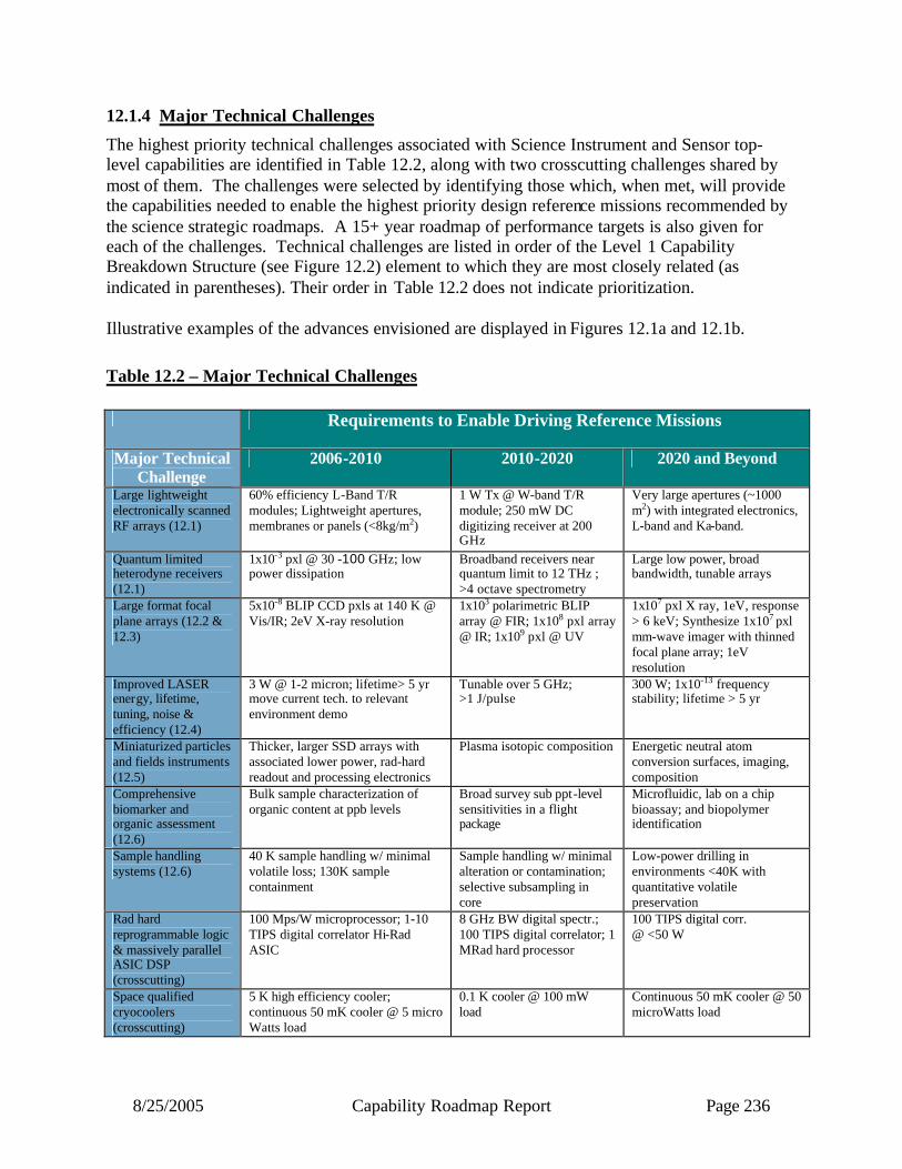
8/25/2005 Capability Roadmap Report Page 236
12.1.4 Major Technical Challenges
The highest priority technical challenges associated with Science Instrument and Sensor top-level capabilities are identified in Table 12.2, along with two crosscutting challenges shared by most of them. The challenges were selected by identifying those which, when met, will provide the capabilities needed to enable the highest priority design reference missions recommended by the science strategic roadmaps. A 15+ year roadmap of performance targets is also given for each of the challenges. Technical challenges are listed in order of the Level 1 Capability Breakdown Structure (see Figure 12.2) element to which they are most closely related (as indicated in parentheses). Their order in Table 12.2 does not indicate prioritization. Illustrative examples of the advances envisioned are displayed in Figures 12.1a and 12.1b. Table 12.2 – Major Technical Challenges
Requirements to Enable Driving Reference Missions
Major Technical Challenge
2006-2010 2010-2020 2020 and Beyond
Large lightweight electronically scanned RF arrays (12.1)
60% efficiency L-Band T/R modules; Lightweight apertures, membranes or panels (<8kg/m2)
1 W Tx @ W-band T/R module; 250 mW DC digitizing receiver at 200 GHz
Very large apertures (~1000 m2) with integrated electronics, L-band and Ka-band.
Quantum limited heterodyne receivers (12.1)
1x10⁻³ pxl @ 30 -100 GHz; low power dissipation
Broadband receivers near quantum limit to 12 THz ; >4 octave spectrometry
Large low power, broad bandwidth, tunable arrays
Large format focal plane arrays (12.2 & 12.3)
5x10⁻⁸ BLIP CCD pxls at 140 K @ Vis/IR; 2eV X-ray resolution
1x10³ polarimetric BLIP array @ FIR; 1x10⁸ pxl array @ IR; 1x10⁹ pxl @ UV
1x10⁷ pxl X ray, 1eV, response > 6 keV; Synthesize 1x10⁷ pxl mm-wave imager with thinned focal plane array; 1eV resolution
Improved LASER energy, lifetime, tuning, noise & efficiency (12.4)
3 W @ 1-2 micron; lifetime> 5 yr move current tech. to relevant environment demo
Tunable over 5 GHz; >1 J/pulse
300 W; 1x10-13 frequency stability; lifetime > 5 yr
Miniaturized particles and fields instruments (12.5)
Thicker, larger SSD arrays with associated lower power, rad-hard readout and processing electronics
Plasma isotopic composition Energetic neutral atom conversion surfaces, imaging, composition
Comprehensive biomarker and organic assessment (12.6)
Bulk sample characterization of organic content at ppb levels
Broad survey sub ppt-level sensitivities in a flight package
Microfluidic, lab on a chip bioassay; and biopolymer identification
Sample handling systems (12.6)
40 K sample handling w/ minimal volatile loss; 130K sample containment
Sample handling w/ minimal alteration or contamination; selective subsampling in core
Low-power drilling in environments <40K with quantitative volatile preservation
Rad hard reprogrammable logic & massively parallel ASIC DSP (crosscutting)
100 Mps/W microprocessor; 1-10 TIPS digital correlator Hi-Rad ASIC
8 GHz BW digital spectr.; 100 TIPS digital correlator; 1 MRad hard processor
100 TIPS digital corr. @ <50 W
Space qualified cryocoolers (crosscutting)
5 K high efficiency cooler; continuous 50 mK cooler @ 5 micro Watts load
0.1 K cooler @ 100 mW load
Continuous 50 mK cooler @ 50 microWatts load

8/25/2005 Capability Roadmap Report Page 237
1.00E+00
1.00E+01
1.00E+02
1.00E+03
1.00E+04
1.00E+05
1.00E+06
1.00E+07
1.00E+08
1.00E+09
1.00E+10
2005 2007 2009 2011 2013 2015 2017 2019 2021 2023
Technology Need Date
Num
ber o
f Pix
els
FIR Bolometer IR Photodiode/Mux Visible CCD/APS UV MCP UV CCD/APS X-ray CCD X-ray Microcalorimeter
LUVO
TPF-CJDEM
MTRAPGen-X
SAFIR
Inflation ProbeCon-X
SOA
SOA
Figure 12.1a: Multi-Spectral/Imaging Sub-Capability Needs for Large Format Focal Plane Arrays
Mars Sample ReturnSOA
SAFIR Gen-XCon-XEinstein Inflation Probe
Einstein Inflation Probe
SOA
0.01
0.10
1.00
10.00
100.00
2005 2007 2009 2011 2013 2015 2017 2019 2021 2023 2025
Technology Need Date
Tem
pera
ture
(K)
Mechanical Cryocooler Ultra Low Temp Cooler
Con-X
SAFIR
Gen-X
Figure 12.1b: Crosscutting Sub-Capability Needs for Flight Qualified Cryocooler, Long Life, Low Mass Active Cooling Systems

8/25/2005 Capability Roadmap Report Page 238
12.1.5 Key Capabilities and Status
In this section we describe the most important sub-capabilities, selected from a list of over 100 candidates. The following selection criteria were applied:
• Do they enable or enhance scientific discovery linked to the Vision for Space Exploration? • Do they have broad application across science instrument and sensor capabilities? • Do they meet the needs of multiple design reference missions? These sub–capabilities are shown in Table 12.3 where Current Status refers to performance levels that have been demonstrated in a relevant space environment. No prioritization among the 10 sub-capabilities was attempted. Table 12.3 - Key Capabilities
Capability
Sub-
Capability
Missions Enabled
Current Status
Min Dev Time (Yrs)
12.1 Microwave Instruments and Sensors
Integrated radar T/R modules
L-Band LEO InSAR, L-Band MEO InSAR, Ocean Structure and Circulation, LEO Cloud System Structure, InSAR Land Topomapper
10-30W, 40% efficient; 4-5 chip MCM, $1K/module, Tx/Rx only
3
12.1 Microwave Instruments and Sensors
Integrated radiometer receivers
Jupiter Polar Orbiter with Probes, Sea Ice Thickness, Einstein Inflation Probe, Global Tropospheric Aerosols, Mars Electrification Imager
THz Receivers: 100 element array at 100 GHz; 2 THz but not cryogenic; Digitizing MMIC Receivers: 500 mW at < 60 GHz
5
12.2 Multi-Spectral Imaging / Spectroscopy (Vis -IR-FIR)
Visible, Near and Far-IR Detector Arrays and Readouts
TPF-C, Joint Dark Energy Mission, Magnetic Transition Region Probe, GEO Lightning Imager
Vis: 2k x 4k pixels, CCD; NIR: 2k x 2k pixels, photodiode/multiplexer FIR: ~ 400 pixels, bolometer array, NEP ~ 10-18 W/vHz, unproven multiplexing
5
12.1 Microwave Instruments and Sensors 12.2 Multi-Spectral Imaging / Spectroscopy (Vis -IR-FIR) 12.3 Multi-Spectral Sensing
Active Cooling ystems
Einstein Inflation Probe, Single Aperture Far Infrared Observatory, Neptune Orbiter with Probes, Joint Dark Energy Mission, Life Finder, Planet Imager, Constellation-X, Generation-X
>50 K: standard flight technology 30-50 K: in qualification 4K-30 K: in lab development Intermittent sub-Kelvin cooling: in service continuous sub-Kelvin cooling: breadboard validation cryogen-free interface with mechanical cooler: proof of concept
5

8/25/2005 Capability Roadmap Report Page 239
Capability
Sub-
Capability
Missions Enabled
Current Status
Min Dev Time (Yrs)
12.4 Laser / LIDAR Remote Sensing 12.5 Direct Sensing of Fields, Particles, and Waves
Lasers: Lifetime, High Power, High Frequency Stability
Lunar Recon Orbiter, Stratosphere Composition, Mars High Resolution Spatial Mapper, Laser Interferometer Space Antenna, Global Troposhere Winds, Stratospheric Composition, Photosynthetic Efficiency, Big Bang Observer, Europa Geophysical Explorer, Advanced Land Cover Change
6x10⁸ shots in space; 10-11 noise in lab; 30 mW in lab; no tunable or frequency stable designs space qualified.
5
12.1 Microwave Instruments and Sensors
12.3 Multi-Spectral Sensing (UV-Gamma)
12.5 Direct Sensing of Fields, Particles, and Waves
Low power, radiation hard electronics
L-Band MEO InSAR, Sea Ice Thickness, Global Tropospheric Aerosols, GEO Global Precipitation Doppler Radar/Passive Imager, Europa Geophysical Orbiter, Solar Probe, All multi-spacecraft missions
1 Tera instructions per second; Microprocessor: ~ 10 Mps/W; DC/DC Conv.: effic. ~ 20 - 50%; A/D Conv.: 14 bits, 10 MHz, 250 mW; HVPS; 150-400 gm Readout Analog Electronics: 106 channels, 100 µW/channel, 200 e rms noise/channel
5
12.5 Direct Sensing of Fields, Particles, and Waves
Particle detectors with integrated electronics
Europa Geophysical Orbiter, Inner Heliosphere Sentinels (IHS), Solar Probe, Mag Con, Telemachus, Interstellar Probe (ISP), Heliospheric Imager and Galactic Observer (HIGO)
Solid state detector energy thresholds = 10 keV; Limited arrays and higher power; Soft integrated electronics
5
12.6 In Situ Instrumentation
Comprehensive biomarker and organic assessment
Mars Deep Drill, Mars Foundation Laboratory, Titan Explorer, Europa Pathfinder Lander, Europa Astrobiology Lander
Terrestrial lab-based systems for sub-ppt level sensitivity; non-comprehensive ppb-level sensitivity in bulk samples for flight prototypes
5
12.6 In Situ Instrumentation
Sample handling with minimal sample alteration or contamination
Lunar Polar Explorer, Comet Surface Sample Return, Comet Cryo Sample Return, Mars Deep Drill, Europa Pathfinder Lander, Mercury Sample Return, Comet Surface Sample Return, Venus In Situ Explorer, Europa Pathfinder Lander
MER rock abrasion tool, Phoenix sample acquisition
5
8/25/2005 Capability Roadmap Report Page 240
12.2 Roadmap Development 12.2.1 Legacy Activities and Roadmap Assumptions Science Instrument and Sensor capability needs can be traced directly back to the following top-level strategic documents:
The Vision for Space Exploration The New Age of Exploration: NASA Strategic Objectives for 2005 and Beyond A Journey to Inspire, Innovate, and Discover: (Aldridge Commission Report) Our Changing Planet: The US Climate Change Science Program for Fiscal Years 2004, 2005 NASA Enterprise Strategies:
• Earth Science Application Plan • Earth Science Research Plan (Draft) • Solar System Exploration - 2000 to 2035 (Draft 3) • Sun-Earth Connection Roadmap (2003-2028) • Physics of the Universe: A Strategic Plan for Federal Research • Solar System Exploration Roadmap • Origins Roadmap (2003) • Structure and Evolution of the Universe Roadmap
National Research Council Reports:
• Astronomy and Astrophysics in the New Millennium - Astronomy and Astrophysics Survey Committee, Board on Physics and Astronomy, Space Studies Board
• Implementing Climate and Global Change Research: A Review of the Final U.S. Climate Change Science Program Strategic Plan - Committee to Review the U.S. Climate Change Science Program Strategic Plan
• New Frontiers in the Solar System: An Integrated Exploration Strategy - Solar System Exploration Strategy
• Solar and Space Physics and Its Role in Space Exploration - Committee on Assessment of the Role of Solar and Space Physics in NASA's Space Exploration Initiative
• The Sun to the Earth -- and Beyond: A Decadal Research Strategy in Solar and Space Physics - Solar and Space Physics Survey Committee
• The Sun to the Earth -- and Beyond: Panel Reports - Solar and Space Physics Survey Committee, Committee on Solar and Space Physics
• Connecting Quarks with the Cosmos: Eleven Science Questions for the New Century, Committee on the Physics of the Universe
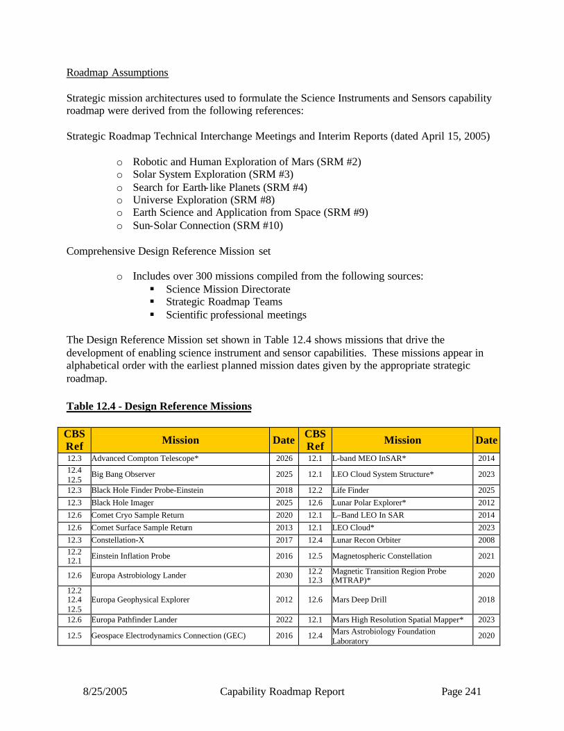
8/25/2005 Capability Roadmap Report Page 241
Roadmap Assumptions Strategic mission architectures used to formulate the Science Instruments and Sensors capability roadmap were derived from the following references: Strategic Roadmap Technical Interchange Meetings and Interim Reports (dated April 15, 2005)
o Robotic and Human Exploration of Mars (SRM #2) o Solar System Exploration (SRM #3) o Search for Earth- like Planets (SRM #4) o Universe Exploration (SRM #8) o Earth Science and Application from Space (SRM #9) o Sun-Solar Connection (SRM #10)
Comprehensive Design Reference Mission set
o Includes over 300 missions compiled from the following sources: § Science Mission Directorate § Strategic Roadmap Teams § Scientific professional meetings
The Design Reference Mission set shown in Table 12.4 shows missions that drive the development of enabling science instrument and sensor capabilities. These missions appear in alphabetical order with the earliest planned mission dates given by the appropriate strategic roadmap. Table 12.4 - Design Reference Missions CBS Ref Mission Date CBS
Ref Mission Date
12.3 Advanced Compton Telescope* 2026 12.1 L-band MEO InSAR* 2014 12.4 12.5
Big Bang Observer 2025 12.1 LEO Cloud System Structure* 2023
12.3 Black Hole Finder Probe-Einstein 2018 12.2 Life Finder 2025 12.3 Black Hole Imager 2025 12.6 Lunar Polar Explorer* 2012 12.6 Comet Cryo Sample Return 2020 12.1 L–Band LEO In SAR 2014 12.6 Comet Surface Sample Return 2013 12.1 LEO Cloud* 2023 12.3 Constellation-X 2017 12.4 Lunar Recon Orbiter 2008 12.2 12.1 Einstein Inflation Probe 2016 12.5 Magnetospheric Constellation 2021
12.6 Europa Astrobiology Lander 2030 12.2 12.3
Magnetic Transition Region Probe (MTRAP)* 2020
12.2 12.4 12.5
Europa Geophysical Explorer 2012 12.6 Mars Deep Drill 2018
12.6 Europa Pathfinder Lander 2022 12.1 Mars High Resolution Spatial Mapper* 2023
12.5 Geospace Electrodynamics Connection (GEC) 2016 12.4 Mars Astrobiology Foundation Laboratory
2020
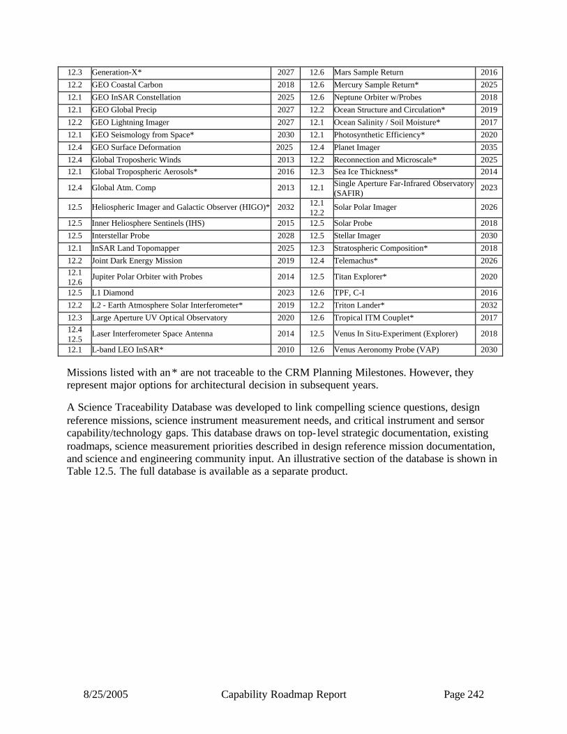
8/25/2005 Capability Roadmap Report Page 242
12.3 Generation-X* 2027 12.6 Mars Sample Return 2016 12.2 GEO Coastal Carbon 2018 12.6 Mercury Sample Return* 2025 12.1 GEO InSAR Constellation 2025 12.6 Neptune Orbiter w/Probes 2018 12.1 GEO Global Precip 2027 12.2 Ocean Structure and Circulation* 2019 12.2 GEO Lightning Imager 2027 12.1 Ocean Salinity / Soil Moisture* 2017 12.1 GEO Seismology from Space* 2030 12.1 Photosynthetic Efficiency* 2020 12.4 GEO Surface Deformation 2025 12.4 Planet Imager 2035 12.4 Global Troposheric Winds 2013 12.2 Reconnection and Microscale* 2025 12.1 Global Tropospheric Aerosols* 2016 12.3 Sea Ice Thickness* 2014
12.4 Global Atm. Comp 2013 12.1 Single Aperture Far-Infrared Observatory (SAFIR)
2023
12.5 Heliospheric Imager and Galactic Observer (HIGO)* 2032 12.1 12.2
Solar Polar Imager 2026
12.5 Inner Heliosphere Sentinels (IHS) 2015 12.5 Solar Probe 2018 12.5 Interstellar Probe 2028 12.5 Stellar Imager 2030 12.1 InSAR Land Topomapper 2025 12.3 Stratospheric Composition* 2018 12.2 Joint Dark Energy Mission 2019 12.4 Telemachus* 2026 12.1 12.6
Jupiter Polar Orbiter with Probes 2014 12.5 Titan Explorer* 2020
12.5 L1 Diamond 2023 12.6 TPF, C-I 2016 12.2 L2 - Earth Atmosphere Solar Interferometer* 2019 12.2 Triton Lander* 2032 12.3 Large Aperture UV Optical Observatory 2020 12.6 Tropical ITM Couplet* 2017 12.4 12.5
Laser Interferometer Space Antenna 2014 12.5 Venus In Situ-Experiment (Explorer) 2018
12.1 L-band LEO InSAR* 2010 12.6 Venus Aeronomy Probe (VAP) 2030 Missions listed with an * are not traceable to the CRM Planning Milestones. However, they represent major options for architectural decision in subsequent years. A Science Traceability Database was developed to link compelling science questions, design reference missions, science instrument measurement needs, and critical instrument and sensor capability/technology gaps. This database draws on top- level strategic documentation, existing roadmaps, science measurement priorities described in design reference mission documentation, and science and engineering community input. An illustrative section of the database is shown in Table 12.5. The full database is available as a separate product.
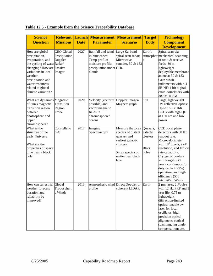
8/25/2005 Capability Roadmap Report Page 243
Table 12.5 - Example from the Science Traceability Database
Science Question
Relevant Missions
Launch Date
Measurement Parameter
Measurement Scenario
Target Body
Technology Component
Development How are global precipitation, evaporation, and the cycling of water changing? How are variations in local weather, precipitation and water resources related to global climate variation?
GEO Global Precipitation Doppler Radar/ Passive Imager
2027 Rainfall and wind in hurricanes; Temp profile; moisture profile; precipitation under clouds
Large Ka-band spiral-scan radar; Microwave sounder, 50 & 183 GHz
Earth's atmosphere
Spiral scan via mechanical scanning of xmit & receive feeds; 30 m lightweight deployable membrane antenna; 50 & 183 GHz MMIC radiometers with < 4 dB NF; 1-bit digital cross-correlators with 200 MHz BW
What are dynamics of Sun's magnetic transition region between photosphere and upper chromosphere?
Magnetic Transition Region Probe
2020 Velocity (vector if possible) and vector magnetic fields in chromosphere/ corona
Doppler Imager/ Magnetograph
Sun Large, lightweight UV reflective optics; Up to 16K x 16K CCDs with high QE at 150 nm and low power
What is the structure of the early Universe What are the properties of space time near a black hole
Constellation-X
2017 Imaging Spectroscopy
Measure the x-ray spectra of distant quasars and earliest galactic clusters X-ray spectra of matter near black hole
Quasars, galactic clusters Black holes
CCD focal plane detectors with 30 Hz readout rate. Microcalorimeter with 103 pixels, 2 eV resolution, and 103 c/s rate capability. Cryogenic coolers with long-life (7 year), continuous (or duty cycle > 95%) operation, and high efficiency (500 microWatt/Watt)
How can terrestrial weather forecast duration and reliability be improved?
Global Tropospheric Winds
2013 Atmospheric wind profile
Direct Doppler or coherent LIDAR
Earth 2 µm laser, 2 J/pulse with 12 Hz PRF and 3 year life; 0.75 m lightweight diffraction-limited optics; tunable cw laser for local oscillator; high precision optical alignment; conical scanning; lag-angle compensation; etc.
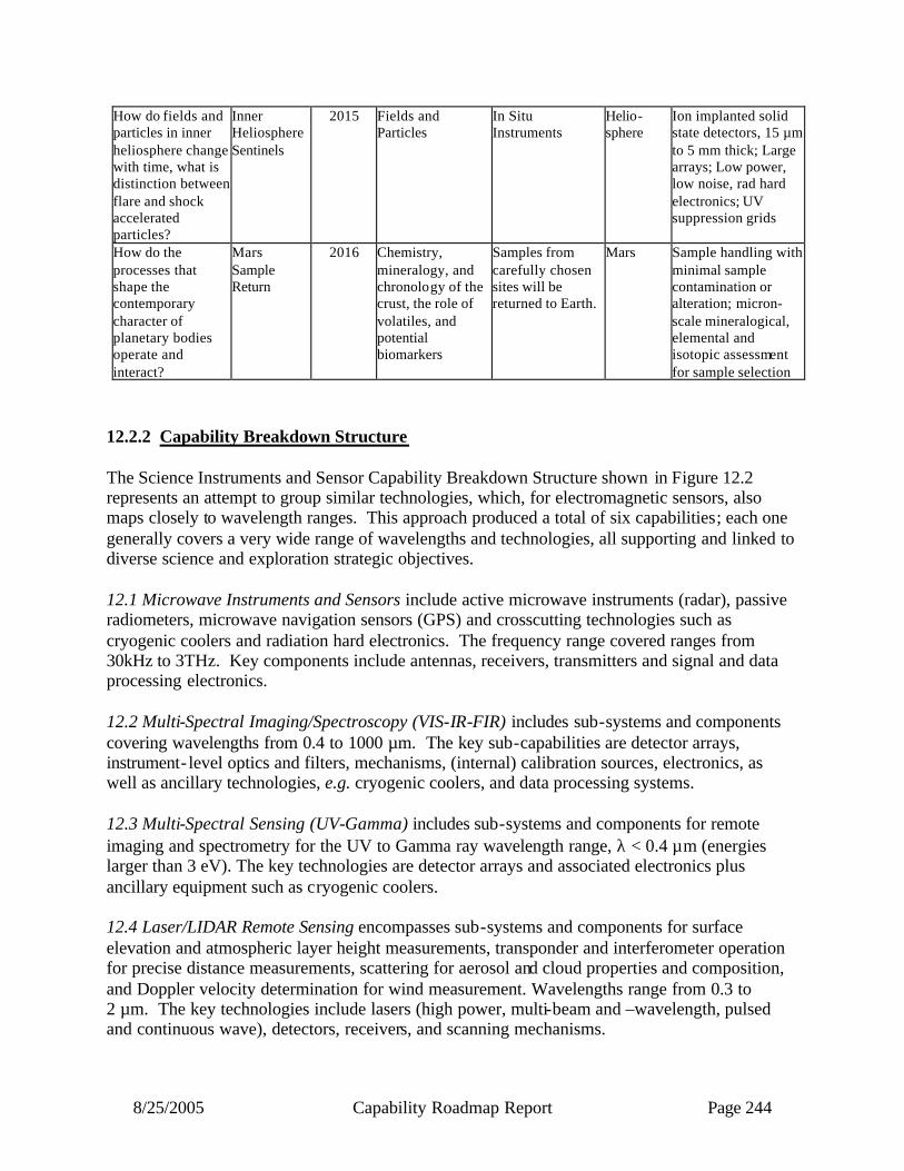
8/25/2005 Capability Roadmap Report Page 244
How do fields and particles in inner heliosphere change with time, what is distinction between flare and shock accelerated particles?
Inner Heliosphere Sentinels
2015 Fields and Particles
In Situ Instruments
Helio-sphere
Ion implanted solid state detectors, 15 µm to 5 mm thick; Large arrays; Low power, low noise, rad hard electronics; UV suppression grids
How do the processes that shape the contemporary character of planetary bodies operate and interact?
Mars Sample Return
2016 Chemistry, mineralogy, and chronology of the crust, the role of volatiles, and potential biomarkers
Samples from carefully chosen sites will be returned to Earth.
Mars Sample handling with minimal sample contamination or alteration; micron-scale mineralogical, elemental and isotopic assessment for sample selection
12.2.2 Capability Breakdown Structure The Science Instruments and Sensor Capability Breakdown Structure shown in Figure 12.2 represents an attempt to group similar technologies, which, for electromagnetic sensors, also maps closely to wavelength ranges. This approach produced a total of six capabilities; each one generally covers a very wide range of wavelengths and technologies, all supporting and linked to diverse science and exploration strategic objectives. 12.1 Microwave Instruments and Sensors include active microwave instruments (radar), passive radiometers, microwave navigation sensors (GPS) and crosscutting technologies such as cryogenic coolers and radiation hard electronics. The frequency range covered ranges from 30kHz to 3THz. Key components include antennas, receivers, transmitters and signal and data processing electronics. 12.2 Multi-Spectral Imaging/Spectroscopy (VIS-IR-FIR) includes sub-systems and components covering wavelengths from 0.4 to 1000 µm. The key sub-capabilities are detector arrays, instrument- level optics and filters, mechanisms, (internal) calibration sources, electronics, as well as ancillary technologies, e.g. cryogenic coolers, and data processing systems. 12.3 Multi-Spectral Sensing (UV-Gamma) includes sub-systems and components for remote imaging and spectrometry for the UV to Gamma ray wavelength range, λ < 0.4 µm (energies larger than 3 eV). The key technologies are detector arrays and associated electronics plus ancillary equipment such as cryogenic coolers. 12.4 Laser/LIDAR Remote Sensing encompasses sub-systems and components for surface elevation and atmospheric layer height measurements, transponder and interferometer operation for precise distance measurements, scattering for aerosol and cloud properties and composition, and Doppler velocity determination for wind measurement. Wavelengths range from 0.3 to 2 µm. The key technologies include lasers (high power, multi-beam and –wavelength, pulsed and continuous wave), detectors, receivers, and scanning mechanisms.

8/25/2005 Capability Roadmap Report Page 245
12.5 Direct Sensing of Particles, Fields and Waves includes capabilities for in situ and remote sensing of particles (ions, electrons, neutral atoms, neutrons, cosmic rays); DC electric and magnetic fields, plasma waves, and gravity fields and waves. The sub-capability includes energetic particle and plasma imagers and spectrometers, high-energy particle detectors, magnetometers, electric fields and waves sensors, and gravitational waves and fields instruments. 12.6 In Situ Instrumentation required by future NASA missions ranges from close range electromagnetic sensors to the full gamut of analytical chemistry and modern molecular biology techniques. Techniques for acquiring, handling, processing, and storing samples are required. In addition to miniaturizing traditional laboratory size equipment, the instruments must be capable of operating in extreme environmental conditions of temperature, radiation, pressure, and corrosiveness, potentially with stringent planetary protection requirements.
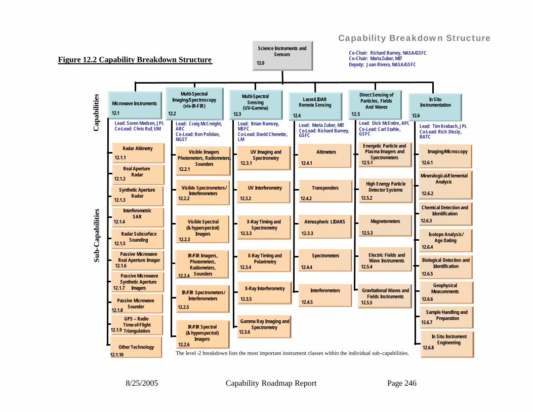
8/25/2005 Capability Roadmap Report Page 246
Figure 12.2 Capability Breakdown Structure
GPS – Radio Time-of-FlightTriangulation
Capability Breakdown Structure
Microwave Instruments
Lead: Soren Madsen, JPLCo-Lead: Chris Ruf, UM
Radar Altimetry
12.1.1
12.1.2
Real Aperture Radar
Synthetic ApertureRadar
12.1.3
12.1.4
InterferometricSAR
Lead: Craig McCreight, ARCCo-Lead: Ron Polidan, NGST
Visible Imagers Photometers, Radiometers,
Sounders12.2.1
12.2.2
Visible Spectrometers/Interferometers
Visible Spectral(& hyperspectral)
Imagers12.2.3
Lead: Brian Ramsey, MSFCCo-Lead: David Chenette, LM
UV Imaging andSpectrometry
12.3.1
12.3.2
UV Interferometry
X-Ray Timing andSpectrometry
12.3.3
12.3.4
X-Ray Timing andPolarimetry
Lead: Maria Zuber, MITCo-Lead: Richard Barney, GSFC
Altimeters
12.4.1
12.4.2
Transponders
Atmospheric LIDARS
12.3.3
12.4.4
Spectrometers
Lead: Dick McEntire, APLCo-Lead: Carl Stahle , GSFC
Energetic Particle andPlasma Imagers and
Spectrometers12.5.1
12.5.2
High Energy ParticleDetector Systems
Magnetometers
12.5.3
12.5.4
Electric Fields andWave Instruments
Lead: Tim Krabach, JPLCo-Lead: Rich Dissly, BATC
Imaging/Microscopy
12.6.1
12.6.2
Mineralogical/ElementalAnalysis
Chemical Detection andIdentification
12.6.3
12.6.4
Isotope Analysis/Age Dating
12.2 12.3 12.4 12.5 12.6
Multi-SpectralImaging/Spectroscopy
(vis-IR-FIR)
Multi-SpectralSensing
(UV-Gamma)
Laser/LIDARRemote Sensing
Direct Sensing ofParticles, Fields
And Waves
In SituInstrumentation
Interferometers
12.4.5
Gravitational Waves andFields Instruments
12.5.5
Biological Detection andIdentification
12.6.5
12.6.6
GeophysicalMeasurements
Science Instruments and Sensors Co-Chair: Richard Barney, NASA/GSFC
Co-Chair: Maria Zuber, MIT Deputy: Juan Rivera, NASA/GSFC
Radar SubsurfaceSounding
12.1.5
Passive MicrowaveReal Aperture Imager
12.1.6
Passive MicrowaveSounder
12.1.8
12.1.9
Other Technology
12.1.10
Passive MicrowaveSynthetic Aperture
Imagers12.1.7
IR/FIR Imagers, Photometers, Radiometers,
Sounders12.2.4
12.2.5
12.2.6
IR/FIR Spectrometers/Interferometers
IR/FIR Spectral(& hyperspectral)
Imagers
X-Ray Interferometry
Gamma Ray Imaging andSpectrometry
12.3.5
12.3.6
Sample Handling and Preparation
In Situ InstrumentEngineering
12.6.7
12.6.8
12.1
12.0
Cap
abili
ties
Sub-
Cap
abili
ties
The level -2 breakdown lists the most important instrument classes within the individual sub-capabilities.
8/25/2005 Capability Roadmap Report Page 247
12.2.3 Roadmap Logic The capability roadmap in this report is a summary- level roadmap. This summary level roadmap includes only a roll up of the key sub-capabilities milestone readiness to support a particular mission requirement. Detailed sub-capability and technology roadmaps showing the technology progression and sub-capability development were presented to the NAS and are available via CD. The blue banner includes key missions derived from the April 15, 2005 interim material delivered by the strategic roadmaps and displayed in the CRM Planning Milestones Chart. The green banner represents a summary rollup of key capabilities from each of the various capability breakdown structure elements. The peach-colored swim-lanes are top- level capability breakdown structure elements and the sub-capabilities within this roadmap. The triangles represent the date that the capability is ready to support a given mission, and the diamonds are decision points. The Science Instrument and Sensor capability roadmap, shown in Figures 12.3 and 12.4, is the result of intensive analysis of NASA’s future mission plans as peer reviewed by a number of science and exploration individuals and teams. Launch dates of missions and corresponding major technology events or demonstrations of technical maturity in a relevant environment are typically separated by about five years to represent technology infusion, as indicated by color and letter coding.
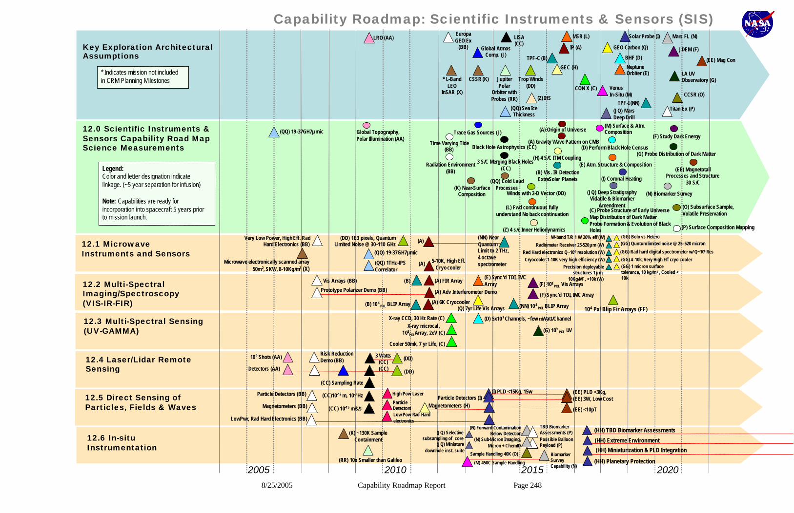
8/25/2005 Capability Roadmap Report Page 248
12.5 Direct Sensing of Particles, Fields & Waves
Capability Roadmap: Scientific Instruments & Sensors (SIS)
2005 2010 20202015
Key Exploration Architectural Assumptions
12.0 Scientific Instruments & Sensors Capability Road MapScience Measurements
LRO (AA)EuropaGEO Ex
(BB)
LISA (CC)
Global AtmosComp. (J)
CSSR (K) Trop Winds (DD)
MSR (L)
IP (A)
TPF-C (B)
GEC (H)
CON X (C)
Solar Probe (I)
GEO Carbon (Q)
BHF (D)
NeptuneOrbiter (E)
Venus In-Situ (M) CCSR (O)
Titan Ex (P)
LA UV Observatory (G)
Mars FL (N)
JDEM (F)
(EE) Mag Con
Global Topography, Polar Illumination (AA)
Time Varying Tide (BB)
Radiation Environment (BB)
Trace Gas Sources (J)
(K) Near-Surface Composition
Black Hole Astrophysics (CC)
(A) Origin of Universe
(B) Vis. IR Detection ExtraSolar Planets
Winds with 2-D Vector (DD)
(L) Fwd continuous fully understand No back continuation
(C) Probe Structure of Early UniverseMap Distribution of Dark MatterProbe Formation & Evolution of Black Holes
(E) Atm. Structure & Composition
(D) Perform Black Hole Census
(M) Surface & Atm. Composition
(I) Coronal Heating
(P) Surface Composition Mapping
(O) Subsurface Sample, Volatile Preservation
(N) Biomarker Survey
(F) Study Dark Energy
(G) Probe Distribution of Dark Matter
(EE) MagnetotailProcesses and Structure
30 S/C
(H) 4 S/C ITM Coupling
12.1 Microwave Instruments and Sensors
12.2 Multi-Spectral Imaging/Spectroscopy (VIS-IR-FIR)
12.3 Multi-Spectral Sensing (UV-GAMMA)
12.4 Laser/Lidar Remote Sensing
(DD) 1E3 pixels, Quantum Limited Noise @ 30-110 GHz
(NN) Near Quantum Limit to 2 THz, 4 octave spectrometer
5-10K, High Eff. Cryo cooler
Vis Arrays (BB)
Prototype Polarizer Demo (BB)
(A) FIR Array
(A) Adv Interferometer Demo
(NN) 104 PXL BLIP Array
X-ray CCD, 30 Hz Rate (C)X-ray microcal,
103PXLArray, 2eV (C)
Cooler 50mk, 7 yr Life, (C)
109 Shots (AA)Risk Reduction Demo (BB)
Detectors (AA)
3 Watts (CC)
(CC) Sampling Rate
Particle Detectors (BB)
Magnetometers (BB)
LowPwr, Rad Hard Electronics (BB)
12.6 In-situ Instrumentation
(K) ~130K Sample Containment
(RR) 10x Smaller than Galileo (M) 450C Sample Handling
(Q) 7yr Life Vis Arrays
(E) Sync ’d TDI, IMC Array (F) 108
PXL Vis Arrays
(D) 5x10⁷ Channels, ~few µWatt/Channel
(CC)10-12 m, 10-3 Hz
(CC) 10-15 m/s/s
(I) PLD <15Kg, 15w (EE) PLD <3Kg, (EE) 3W, Low Cost
TBD Biomarker Assessments (P)Possible Balloon Payload (P)
Sample Handling 40K (O)
(N) Forward Contamination Below Detection
(N) Sub-Micron Imaging, Micron + ChemID
(A) Gravity Wave Pattern on CMB
3 S/C Merging Black Holes (CC)
(EE) <10pT
TPF-I (NN)
(B) 104 PXL BLIP Array
(F) Sync’d TDI, IMC Array
Magnetometers (H)Particle Detectors (I)
(G) 109PXL UV
Biomarker Survey Capability (N)
* L-Band LEO
InSAR (X)
Very Low Power, High Eff. RadHard Electronics (BB)
Microwave electronically scanned array 50m2, SKW, 8-10Kg/m2 (X)
(A)
(A)
(B)
(DD)
(DD)(CC)
Legend:Color and letter designation indicate linkage. (~5 year separation for infusion)
Note: Capabilities are ready for incorporation into spacecraft 5 years prior to mission launch.
Legend:Color and letter designation indicate linkage. (~5 year separation for infusion)
Note: Capabilities are ready for incorporation into spacecraft 5 years prior to mission launch.
(HH) TBD Biomarker Assessments
(HH) Extreme Environment
(HH) Planetary Protection
(HH) Miniaturization & PLD Integration
(GG) Quntum limited noise @ 25-520 micron
(GG) Rad hard digital spectrometer w/ Q~108 Res
(GG) 1 micron surface tolerance, 10 kg/m 2 , Cooled < 10k
W-band T/R 1 W 20% eff (W)
Red Hard electronics Q~10-6 resolution (W)Cryocooler 1-10K very high efficiency (W)
(GG) Bolo vs Hetero
(GG) 4-10k, Very High Eff cryo cooler
Radiometer Receiver 25-520µm (W)
Precision deployable structures 1µm;
10Kg/M2 , <10k (W)
104 Pxl Blip Fir Arrays (FF)
* Indicates mission not included in CRM Planning Milestones* Indicates mission not included in CRM Planning Milestones Jupiter
Polar Orbiter with Probes (RR)
(QQ) Sea Ice Thickness
(QQ) Cold Laud Processes
(QQ) 19-37GH7µmic
(QQ) 19-37GH7µmic
(QQ) 1THz-IPS Correlator
(Z) IHS
(JQ) MarsDeep Drill
(Z) 4 s/c Inner Heliodynamics
(JQ) Deep StratigraphyVidatile & Biomarker
Amendment
(A) 6K Cryocooler
(JQ) Selective subsampling of core
(JQ) Miniature downhole inst. suite
High Pow Laser
Particle DetectorsLow Pow Rad Hard electronics

8/25/2005 Capability Roadmap Report Page 249
Capability Roadmap: Scientific Instruments & Sensors (SIS)
2020 2025 20352030
Key Exploration Architectural Assumptions
12.0 Scientific Instruments & Sensors Capability Road MapScience Measurements
Europa Pathfinder Lander (HH)
12.1 Microwave Instruments and Sensors
12.2 Multi-Spectral Imaging / Spectroscopy (VIS-IS-FIR)
12.3 Multi-Spectral Sensing (UV-Gamma)
12.4 Laser / LidarRemote Sensing
12.5 Direct Sensing of Particles, Fields & Waves
12.6 In-Situ Instrumentation
SAFIR (GG)
BHI (S)
BBO (T)
(R) Life Finder
(JJ) Interstellar Probe
Stellar Imager (U)
Europa Lander (V)(LL) Planet
Imager
(R) X Solar Planet
(R) Find Life Conditions
(S) Probe Space-Time Around Black Hole
Gravitational Waves(T)
(JJ) Interstellar Medium
(U) Understand Structure & Dynamics of Stars and Determine Origin of Planets, Life
(V) Detailed Organic Assessment at Extended Depth
(LL) Image XSolarPlanet Detect Atm,
Continents, Ice
(JJ) Very Low Mass & Power
(JJ) Very Light Boom
(JJ) Low Power, Rad Hard Electronics
(JJ) 1pT Magnetometer
Improve Biomarker Detectability
Cold, Fast Drilling
(V)
(V)(V)
3-30µm FPA(R)
(R) High Throughput Stable Optics
(LL) Stable, High-Contrast FPA
0.1 w/ Megapixel X-Ray CCD/APSLarge format
(S) APS / Cryo
UV Cryogenic Detector
(U)
(U)
L1 Diamond (FF)
(T) 3+ S/C Gravitational Wave Background
Miniaturization & PLD Integration
Gen -X (SS)
(SS) Cooler, 50 µW
(SS) X ray 107PXL, 1eV
Mars AFL (N)
* LEO Cloud System (W)(Y) * GEO
Seismologist
(U) RAD Hard Active Electronics (>1 Mrad)
(U) Very Large Light Weight RF Apertures (<2kg/m2)
(HH) Near-Surface Composition & Organic
Survey
Galaxy Evolution (FF)
(GG) Origin of Universe
Star Formation (FF)
4 S/C Solar Wind Turbulence (GG)
(Y) Land Deformation
10-16 m, 1 Hz
10-17 m/s/s
(T)
300 W
Detectors
(T)
(T)
(T) 1 Part in 1013
(T)
Lifetime(T)
Legend:Color and letter designation indicate linkage. (~5 year separation for infusion)
Note: Capabilities are ready for incorporation into spacecraft 5 years prior to mission launch.
Legend:Color and letter designation indicate linkage. (~5 year separation for infusion)
Note: Capabilities are ready for incorporation into spacecraft 5 years prior to mission launch.
* Indicates mission not included in CRM Planning Milestones
* Indicates mission not included in CRM Planning Milestones
(JR) GeoSurface Deformation(Q) GEO Global Precip
(JZ) Venus Aeronomy
(JR) Continuous Measurement of Land Cover
(Q) 10 day forecasts/extreme weather forecast
(JZ) Sampling in extreme environment
(Q) 35 GHz MMIC T/R Module
(Q) 183 GHz MMIC digitizing radiometer(Q) 100 Tera-IPS correlator
(Q) 20 m diameter deployable active array
(JR) Sampling Rate (75kHz)
(JR) High Frequency Stability
(JZ) Extreme Euvir Sample Handling & Processing
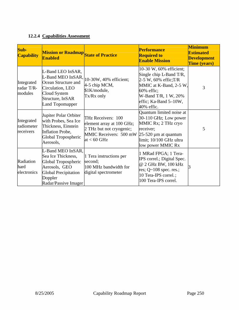
8/25/2005 Capability Roadmap Report Page 250
12.2.4 Capabilities Assessment
Sub-Capability
Mission or Roadmap Enabled
State of Practice Performance Required to Enable Mission
Minimum Estimated Development Time (years)
Integrated radar T/R-modules
L-Band LEO InSAR, L-Band MEO InSAR, Ocean Structure and Circulation, LEO Cloud System Structure, InSAR Land Topomapper
10-30W, 40% efficient; 4-5 chip MCM, $1K/module, Tx/Rx only
10-30 W, 60% efficient; Single chip L-Band T/R, 2-5 W, 60% effic;T/R MMIC at K-Band, 2-5 W, 60% effic; W-Band T/R, 1 W, 20% effic; Ka-Band 5–10W, 40% effic.
3
Integrated radiometer receivers
Jupiter Polar Orbiter with Probes, Sea Ice Thickness, Einstein Inflation Probe, Global Tropospheric Aerosols,
THz Receivers: 100 element array at 100 GHz; 2 THz but not cryogenic; MMIC Receivers: 500 mW at < 60 GHz
Quantum limited noise at 30-110 GHz; Low power MMIC Rx; 2 THz cryo receiver; 25-520 µm at quantum limit; 10/100 GHz ultra low power MMIC Rx
5
Radiation hard electronics
L-Band MEO InSAR, Sea Ice Thickness, Global Tropospheric Aerosols, GEO Global Precipitation Doppler Radar/Passive Imager
1 Tera instructions per second; 100 MHz bandwidth for digital spectrometer
1 MRad FPGA; 1 Tera-IPS correl.; Digital Spec. @ 2 GHz BW, 100 kHz res; Q~108 spec. res.; 10 Tera-IPS correl. ; 100 Tera-IPS correl.
3

8/25/2005 Capability Roadmap Report Page 251
Sub-Capability
Mission or Roadmap Enabled
State of Practice Performance Required to Enable Mission
Minimum Estimated Development Time (years)
Cryocoolers
Einstein Inflation Probe Lab cryocooler 4 – 10 K, high efficiency,
space qualified 3
Precision deployable large structures
L-Band LEO InSAR, L-Band MEO InSAR, Ocean Salinity/Soil Moisture, InSAR Land Topomapper, GEO Global Precipitation Doppler Radar/Passive Imager
Rigid panels, 10-15 kg/m2 plus deployment structure
50 m2 aperture, 9 kg/m2; 400 m2 aperture, 4 kg/m2; 25 m deployable; 1 µm surface, 10 kg/m2, cooled <10K; InSAR 100 m boom at 1 kg/m; metrology compensation; 10-30 m dia active; large deployable reflector at 30-100 m
4
Visible Detector Arrays and Readouts
TPF-C, Joint Dark Energy Mission, Magnetic Transition Region Probe, GEO Lightning Imager
2k x 4k pixel CCD, two-chip focal plane array, conventional drive electronics, ~ 5 electron noise
5x10⁸ BLIP CCD pixels at 140 K, ASIC, 4 electron noise; High contrast FPA with coronagraph; 108 pixels Visible array mosaic, photon counting
5
IR Detector Arrays and Readouts
Neptune Orbiter with Probes, Joint Dark Energy Mission, Life Finder, Planet Imager
2k x 2k pixel near-IR array, lab crycooler, 320 x 240 micro-bolometer array 0.04 K NE ∆T(THEMIS)
2x10⁸ BLIP NIR pixels at 140 K, 4 electron noise, ASIC; 106 room temp array, 0.02 K NE ∆T; 3-17 µm BLIP arrays
5
FIR Detector Arrays and Readouts
Einstein Inflation Probe, Single Aperture Far Infrared Observatory
~ 400 pixel arrays, NEP ~ 10-18 W/vHz, unproven multiplexing, lab cryocoolers
103 pixel BLIP array with polarization sensitivity; 104 pixel BLIP array, 10-18 W/vHz continuous cooling at T <50mK
5

8/25/2005 Capability Roadmap Report Page 252
Sub-Capability
Mission or Roadmap Enabled
State of Practice Performance Required to Enable Mission
Minimum Estimated Development Time (years)
Cryocoolers
Einstein Inflation Probe, Single Aperture Far Infrared Observatory, Neptune Orbiter with Probes, Joint Dark Energy Mission, Life Finder, Planet Imager
>50K: standard flight technology 30-50K: in qualification 4K-30K: in lab development Intermittent sub-Kelvin cooling: in service continuous sub-Kelvin cooling: breadboard validation cryogen-free interface with mechanical cooler: proof of concept
4 – 10 K, high efficiency, space qualified Reliable and continuous 0.1K cooling
3
Instrument Optics and Filters, Advanced Visible and IR Spectrometers
TPF-I, Neptune Orbiter with Probes, L2 Interferometer, GEO Coastal Carbon, Magnetic Transition Region Probe, Single Aperture Far Infrared Observatory, Life Finder
Small scale instruments in space, < Megapixel arrays, ground-based interferometers
IR Imaging FTS, 106 pixels; 8 m boom, 0.1 µm path stability; 103 pixel BLIP array, 10-20 W/vHz; High throughput filter at 10 µm, High contrast FPA Cryocooler at 4-6K
7
Large Format UV Focal Planes, CCD/APS
Large Aperture UV Optical Observatory, Stellar Imager, Magnetic Transition Region Probe
107 pixels, 10-15% quantum efficiency 10 W/Megapixel,
109 pixels, 50% quantum efficiency; 108 pixels (UV), 6k x 6k, buttable, 0.1 W/Megapixel, Extended UV response
5
Large Format X-ray Focal Planes, CCD/APS
Constellation-X, Black Hole Imager, Black Hole Finder
Megapixel, , 120 eV @ 6 keV resolution, 1 Hz readout speed, 150 nm - 6 keV response
4k x 4k, 4-side buttable (X-ray);<120 eV @ 6 keV ; 30 Hz readout speed; X-ray response > 6 keV
5
High Energy Resolution Pixelated Detectors
Constellation-X. Generation-X
36 pixels, 6 eV @ 6 keV resolution, 100 cps per pixel (ASTRO-E2)
2 eV, 103 pixels 1 eV, 107 pixels > 1000 cps per pixel
5

8/25/2005 Capability Roadmap Report Page 253
Sub-Capability
Mission or Roadmap Enabled
State of Practice Performance Required to Enable Mission
Minimum Estimated Development Time (years)
Cryocoolers Constellation-X, Generation-X
Cryogenic coolers: 50 mK, 5 µW, continuous ADR, 300 µW/W efficiency (cryocooler), lifetime not demonstrated
50 mK, 5 µW, continuous or duty cycle > 95% 7 year lifetime 500 µW/W efficiency
3
Mega-to-Giga Channel Analog Electronics
Black Hole Finder Probe
106 channels (GLAST), 100 µW/channel. 200 electrons rms noise/channel (no connections)
5x10⁶ – 108, 100 µW to 2 µW/channel, < 300 e rms with interconnects and coupling
3
Laser Lifetime
Lunar Recon Orbiter, Stratosphere Composition, Mars High Resolution Spatial Mapper, Big Bang Observer
6 x10⁸ shots in space, < 1 year
>109 shots in space, > 5 years 5
Laser Sampling Rate
Laser Interferometer Space Antenna, Advanced Land Cover Change, Mars High Resolution Mapper
40 Hz (space qualified)
75 – 100 kHz 5
High Power Laser
Laser Interfe rometer Space Antenna, Global Troposhere Winds, Stratospheric Composition, Photosynthetic Efficiency, Big Bang Observer
30 mW
3W – 300 W, 300 MJ/pulse, NIR 75 MJ/pulse, Vis 500 MJ/pulse
5
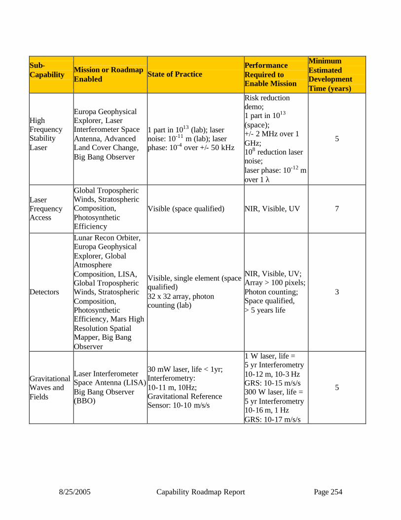
8/25/2005 Capability Roadmap Report Page 254
Sub-Capability
Mission or Roadmap Enabled
State of Practice Performance Required to Enable Mission
Minimum Estimated Development Time (years)
High Frequency Stability Laser
Europa Geophysical Explorer, Laser Interferometer Space Antenna, Advanced Land Cover Change, Big Bang Observer
1 part in 1013 (lab); laser noise: 10-11 m (lab); laser phase: 10-4 over +/- 50 kHz
Risk reduction demo; 1 part in 1013 (space); +/- 2 MHz over 1 GHz; 108 reduction laser noise; laser phase: 10-12 m over 1 λ
5
Laser Frequency Access
Global Tropospheric Winds, Stratospheric Composition, Photosynthetic Efficiency
Visible (space qualified) NIR, Visible, UV 7
Detectors
Lunar Recon Orbiter, Europa Geophysical Explorer, Global Atmosphere Composition, LISA, Global Tropospheric Winds, Stratospheric Composition, Photosynthetic Efficiency, Mars High Resolution Spatial Mapper, Big Bang Observer
Visible, single element (space qualified) 32 x 32 array, photon counting (lab)
NIR, Visible, UV; Array > 100 pixels; Photon counting; Space qualified, > 5 years life
3
Gravitational Waves and Fields
Laser Interferometer Space Antenna (LISA) Big Bang Observer (BBO)
30 mW laser, life < 1yr; Interferometry: 10-11 m, 10Hz; Gravitational Reference Sensor: 10-10 m/s/s
1 W laser, life = 5 yr Interferometry 10-12 m, 10-3 Hz GRS: 10-15 m/s/s 300 W laser, life = 5 yr Interferometry 10-16 m, 1 Hz GRS: 10-17 m/s/s
5

8/25/2005 Capability Roadmap Report Page 255
Sub-Capability
Mission or Roadmap Enabled
State of Practice Performance Required to Enable Mission
Minimum Estimated Development Time (years)
Particle Detectors (plasmas, energetic electrons, ions, neutrals)
Europa Geophysical Orbiter, Inner Heliosphere Sentinels (IHS), Solar Probe, Mag Con, Telemachus, Interstellar Probe (ISP), Heliospheric Imager and Galactic Observer (HIGO)
Solid state detector energy thresholds = 10 keV; Limited arrays and higher power; Soft integrated electronics
Ion implanted SSDs 15 µm to 5 mm thick; Large arrays; Low power, low noise, rad hard electronics; UV suppression grids; Stable charge conversion coatings
3
Vector Magnetometers; Scalar Magnetometers
Europa Geophysical Orbiter, Geospace Electrodynamics Connection, Tropical ITM, Solar Probe, Mag Con, Interstellar Probe (ISP),
Fluxgate: 10 pT, 0.1 nT/week; Scalar (He): 1 pT, 1 ppm; 30 krad electronics; Boom: 3 - 10 m
Low noise core material; Multi-sensor system; Rad hard electronics (~ Mrad); 1 pT vector sensitivity < 1 W; Low resource: < 0.2 W, < 0.1kg
3
Measurement of EM waves; DC Electric Fields
Solar Probe, Interstellar Probe (ISP)
A/D Converter: 8 bits, = 20 Msps at 500 mW; DSP: Non-rad hard, 1 W; Antenna: 50 m spin at 3 kg, 10 m axial at 5 kg
A/D: 18 bits @ 80 Msps @ < 100 mW DSP: Rad hard, 250 mW, 103 pt. FFT at 3 MHz; Antenna: 50 m spin, = 1 kg (inc. sensor); Axial ~ 20 m, rigid, = 2 kg
3
Lower power, radiation hard electronics
Europa Geophysical Orbiter, Solar Probe, All multi-spacecraft missions
Microprocessor: ~ 10 Mps/W; DC/DC Convert: efficiencies ~ 20 - 50%; A/D Converters: 14 bits, 10 MHz at 250 mW; HVPS; 150-400 gm
100 Mps/W, on par with cellphone technology; Efficiencies ~ 85% A/D Converters: = 14 bits, 80 MHz, 50 mW; HVPS: Standard design, <100 gm
3

8/25/2005 Capability Roadmap Report Page 256
Sub-Capability
Mission or Roadmap Enabled
State of Practice Performance Required to
Enable Mission
Minimum Estimated
Development Time (years)
Biomarker Assessment
Mars Deep Drill, Mars Foundation Laboratory, Titan Explorer, Europa Pathfinder Lander, Europa Astrobiology Lander
Lab-based commercial systems
ppb sensitivity and miniaturization to flight scales
5
Lunar Polar Explorer, Comet Surface Sample Return, Comet Cryo Sample Return
Cryomechanisms: MER mobility system 40K demo 3
Mars Deep Drill, Europa Pathfinder Lander, Mercury Sample Return
Subsampling: MER RAT mm-scale sampling of sedimentary layers
5 Sample Handling
Comet Surface Sample Return, Venus In Situ Explorer, Europa Patthfinder Lander
Sample Phase Preservation: Phoenix sample acquisition
No heating of samples above –20C
5
Jupiter Orbiter w/Probes, Mars Foundation Laboratory,
Sensitive assays: subset of viable spores cultivated
Full range of viable life characterized 3
Planetary Protection Jupiter Orbiter
w/Probes, Mars Foundation Laboratory
Contamination control in sample handling: organic contamination in lunar sample of 10s of ppb
Sub-ppb organic contamination in returned samples
3
Chemical ID at small spatial scales
Mars Foundation Laboratory
Miniaturized imaging systems Phoenix AFM; Miniaturized composition probes: Lab-based system
Submicron imaging combined with chemical/isotopic analysis
5
Miniaturization and Payload Integration
Mars Sample Return, Mars Deep Drill, Titan Explorer
Galileo and MER payloads
10x smaller than Galileo, Downhole Instrument Suite, balloon payload
5

8/25/2005 Capability Roadmap Report Page 257
12.2.5 Relationship to Other Roadmaps (capability and strategic) Critical dependencies are highlighted in red; moderate dependencies are highlighted in green. CRMs/SRMs with lower levels of dependence are not included. Table 12.7 - CRM-CRM and CRM-SRM Crosswalks
CRM
* Contributions to SIS
* Contributions from SIS
In-Space Transportation Advanced Telescopes and Observatories
Telescopes and platforms, with particular reliance on large deployable precision structures, and wavefront sensing and control systems. Also critical are formation flying interferometers and active cryo systems
Instruments for which telescopes are deployed; microwave antenna systems; control systems using focal-plane data; telescope metrology systems.
Communication and Navigation High bandwidth communications for high data-rate sensors.
Robotic Access to Planetary Surfaces Access to in situ samples, both surface and subsurface
Instruments for subsurface and atmospheric reconnaissance.
Human Planetary Landing Systems Instruments for surface and atmospheric recon; robotic precursors systems
Human Health and Support Systems Human Exploration Systems and Mobility
Autonomous Systems and Robotics Radiation-hardened processors.
CRM * Contributions to SIS *
Contributions from SIS In Situ Resource Utilization Collection of material for in situ
analysis. Synoptic surveys for resource mapping; in
situ analysis for resource assessment. Advanced Modeling, Simulation, and Analysis
Systems Engineering and Cost/Risk Analysis
Nanotechnology Devices, sensors, actuators, electronics. SRM
Impact of SRM on SIS Work Reliance of SRM on SIS Products
Lunar Exploration In situ analysis; imaging spectrometers; astronomical platforms.
Mars Exploration In situ analysis; imaging spectrometers; high spectral resolution sensors.
Laser altimeters; in situ sampling systems; geological surveying; atmospheric characterization and monitoring.
Solar System Exploration In situ analysis; imaging spectrometers; high spectral resolution sensors.
Laser altimeters; in situ sampling systems; surface surveying; atmospheric characterization and monitoring.
Search for Earth-Like Planets Wide-FOV optics; long-baseline imaging optical interferometers; high spectral resolution sensors.
Wide field-of-view surveys; very high spatial resolution imaging; high sensitivity, high spectral resolution spectrometry.
Universe Exploration Wide-FOV imagers; interferometric gravity wave detection; background-limited sensors across the spectrum.
Large-scale detector arrays; high stability, high precision lasers for gravitational wave detection; sub-mK sensors and coolers.
Earth Science and Applications InSAR; high-resolution passive spatial interferometer; mm-Wave spectrometer High spectral resolution sensors; high-speed, high-sensitivity LIDARs and DIALs; stable long-term calibration.
high precision land deformation; trace gas atmospheric comp; penetration to surface through extreme weather events; troposperic wind profiler
Sun-Solar System Connection Sub-VHF radio systems; solar radar; high-speed imagers/spectrometers.
Imagers; spectrometers; RF systems; magnetometers; particle analysis.

8/25/2005 Capability Roadmap Report Page 258
12.2.6 Critical Facility Assessment
Capability Critical Facility Need Existing Facilities Physical Infrastructure Planning
12.1 Microwave Instruments and Sensors 12.2 Multi-Spectral Imaging / Spectroscopy (Vis-IR-FIR) 12.3 Multi-Spectral Sensing (UV-Gamma)
Stable and high-throughput fabrication infrastructure for large format detector arrays, readout multiplexers, and miniaturized instrument optics High-throughput testing for large format detector arrays
NASA: GSFC (DDL), JPL (MDL) for detector arrays and miniaturized instrument optics; NIST: Detector arrays and superconducting readout multiplexers University: MIT Lincoln Labs, Caltech and UC Berkeley for detector arrays Industry: Rockwell, Raytheon, and BAE for large format IR detector arrays and multiplexer readouts
NASA: GSFC (DCL), JPL, ARC University: Princeton, Caltech, UC Berkeley, MIT, Univ. Hawaii Industry: Vis-IR-UV
Critical for continued development of large format detector arrays. DOD community and commercial industry has little interest in FIR detectors. Sole source in NIST for superconducting readout multiplexers. Detector fab and testing infrastructure requires substantial financial investment, which typical research awards cannot support Many scientific detector arrays (microwave, FIR, IR, X-ray) operate at cryogenic temps, which requires a non–trivial cryogenic testing infrastructure.
12.2 Multi-Spectral Imaging / Spectro-scopy (Vis-IR-FIR)
12.4 Laser / LIDAR Remote Sensing
Instrumented calibration regions Aircraft and ground-based prototype testing
Rogers Dry Lake CA, Stennis Space Center MS, Cuprite NV, Barreal Blanco Argentina, Mt. Fitton and Lake Frome Australia, ocean sites near Hawaii and Bermuda
Critical for instrument calibration of the full field of the instrument over the full spectral range - especially for spectrometric imagers
12.5 Direct Sensing of Fields, Particles and Waves
High charge state ion beam facility, keV energies; Neutral beam facility, 1 eV to 1 MeV; Solar corona simulator
U. Bern RF powered source, GSFC hollow cathode source.
U. Denver O/H facility currently inoperative owing to PI death
Establish NASA high charge state facility for community use Establish NASA neutral atom source and beam facility for community use
12.6 In Situ Instrumentation
Environmentally relevant instrument test beds to simulate conditions on Moon, Mars, Venus, etc.
Mars Yard at JPL; various non-dedicated thermal vacuum chambers
Environmentally relevant testbed will provide an important service to the community and reduce mission risk.

8/25/2005 Capability Roadmap Report Page 259
8/25/2005 Capability Roadmap Report Page 260
12.3 Summary The Science Instruments and Sensors Capability Roadmap Team used current NASA exploration and science measurement strategies, design reference missions, and science instrument/sensor technology roadmaps to identify critical science measurement capability gaps and assess future technology development needs. Several key sub-capabilities were identified that are traceable to the Vision for Exploration and cut across instrument capabilities and science applications. This team concluded that a sustained advanced technology program will be required to narrow or close the identified science instrument and sensor capability gaps and enable several strategic missions. Extensive involvement by the science communities during the process of assessing capability gaps, reinforced critical aspects of NASA’s science instrument and sensor strategic investment processes. The competed, peer reviewed development programs that rely on NASA, government, commercial, and academia partnerships are essential to develop the technology capabilities necessary to achieve NASA’s priority science program.

8/25/2005 Capability Roadmap Report Page 261
Acronym List ADR Adiabatic Demagnetization Refrigerator AFM atomic force microscope APIO Advanced Planning and Integration Office APS Active Pixel Sensor ARC Ames Research Center ASIC application-specific integrated circuit BATC Ball Aerospace and Technologies Corporation BBO Big Bang Observer Mission BHFP Black Hole Finder Probe Mission BHI Black Hole Imager Mission BLIP background limited infrared photo-detector Bolos Bolometer Arrays Bolo v. Hetero Bolometer versus Heterodyne arrays BW Bandwidth CBS Capability Breakdown Structure CCD Charge Coupled Device CMB Cosmic M icrowave Background Con-X Constellation-X Mission CRM Capability Roadmap Cryo cryogenic CSSR Comet Surface Sample Return Mission cw continuous wave DC direct current DCL NASA GSFC Detector Characterization Laboratory DDL NASA GSFC Detector Development Laboratory Demo demonstration DMSP Defense Meteorological Satellite Program DOD Department of Defense DRMs Design Reference Missions DSP Digital Signal Processor chip EG Europa Geophysics Mission EIP Einstein Inflation Probe Mission ESTO Earth Science Technology Office eV Electronvolt Far IR Far Infrared FIR Far Infrared FOV Field- of-View FPA focal plane assembly FPGA Field-Programmable Gate Array FTS Fourier Transform Spectrometer GaAs Gallium Arsenide GEC Geospace Electrodynamics Connection Mission Gen X Generation X Mission GEO Geosynchronous Orbit GEO Coastal C GEO Coastal Carbon Mission GEOSAT Geodetic Satellite Mission GEO Global Precip GEO Global Precipitation (GGP) Mission GHz Giga Hertz GLAST Gamma Ray Large Area Space Telescope GPS Global Positioning System

8/25/2005 Capability Roadmap Report Page 262
GSFC Goddard Space Flight Center GSM Global Soil Moisture Mission GTA Global Tropospheric Aerosols Mission HIGO Heliospheric Imager and Galactic Observer Mission HVPS High Voltage Power Supply IHS Inner Heliosphere Sentinels Mission InSAR Interferometric Synthetic Aperture Radar IPS integrated power systems IR Infrared ISP Interstellar Probe Mission ITSP Ionosphere/Thermosphere Storm Probes Mission J/Pulse Joule/Pulse JDEM Joint Dark Energy Mission JHU John Hopkins University JPL Jet Propulsion Laboratory JPO Jupiter Polar Orbiter Mission JPOP Jupiter Polar Orbiter Probes Mission JWST James Webb Space Telescope LASCO Large Angle and Spectrometric Coronagraph Experiment LASER Light Amplification by Stimulated Emission of Radiation LEO Low Earth Orbit LF Life Finder Mission LIDAR Light Detection and Ranging LISA Laser Interferometer Space Antenna Mission LM Lockheed Martin LRO Lunar Reconnaissance Orbiter LUVO Large Aperture Ultraviolet Optical Observatory Mission L2 Interfr L2 Interferometer Mag Con Magnetic Constellation Mission MC Magnetospheric Constellation Mission MCM multi-chip module MCP Micro-channel Plate MDL NASA JPL Micro-devices Laboratory MEO Mid Earth Orbit MER Mars Exploration Rover MER RAT Mars Exploration Rover Rock Abrasion Tool MIT Massachusetts Institute of Technology mK milliKelvin MMIC Monolithic Microwave Integrated Circuit MMS Magnetospheric Multiscale Mission mmWave millimeter wave Mps megabits per second MRO Mars Reconnaissance Orbiter MSFC Marshall Space Flight Center MSL Mars Surface Laboratory MTRAP Magnetic Transition Region Probe mW milliwatt NEAR NLR Near Laser Rangefinder NEP Noise Equivalent Power NIST National Institute of Standards and Technology NO Neptune Orbiter NOAA National Oceanic and Atmospheric Administration NRC National Research Council

8/25/2005 Capability Roadmap Report Page 263
NRO National Recon. Office- National Reconnaissance Office NSCAT NASA Scatterometer PI Planet Imager Mission ppb parts per billion PRF pulse repetition frequency QE Quantum Efficiency RAM Reconnection and Microscale Mission RBSP Radiation Belt Storm Probes Mission RF Radio Frequency rms root mean square SAFIR Single Aperture Far Infrared Observatory Mission SAR Synthetic Aperture Radar SC Stratospheric Composition Mission S/C Spacecraft SCOPE Solar Connections Observatory for Planetary Environments Mission SEU Structure and Evolution of the Universe SI Stellar Imager Mission SIS Science Instruments and Sensors SIT Sea Ice Thickness Mission SP Solar SIT Probe Mission SPI Solar Probe Imager SRM Strategic Roadmap SSD Solid State Detector TDI Time Delay and Integration THz Terra Hertz THEMIS The History of Events and Macroscale Interactions During Substorms TIPS tera instruction per second TOF Time -of-Flight TPF-C Terrestrial Planet Finder-Coronagraph Mission TPF-I Terrestrial Planet Finder- Interferometer Mission T/R transmitter/receiver TRL Technology Readiness Level Tropical ITM Couplet Tropical ITM Couplet Mission UM University of Michigan UV Ultraviolet UW University of Wisconsin VAP Venus Aeronomy Probe VHF Very High Frequency Vis Visible VISE Venus In Situ Experiment (Explorer) Mission
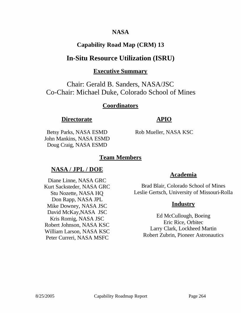
8/25/2005 Capability Roadmap Report Page 264
NASA
Capability Road Map (CRM) 13
In-Situ Resource Utilization (ISRU)
Executive Summary
Chair: Gerald B. Sanders, NASA/JSC Co-Chair: Michael Duke, Colorado School of Mines
Coordinators
Directorate
Betsy Parks, NASA ESMD
John Mankins, NASA ESMD Doug Craig, NASA ESMD
APIO
Rob Mueller, NASA KSC
Team Members
NASA / JPL / DOE
Diane Linne, NASA GRC Kurt Sacksteder, NASA GRC
Stu Nozette, NASA HQ Don Rapp, NASA JPL
Mike Downey, NASA JSC David McKay,NASA JSC Kris Romig, NASA JSC
Robert Johnson, NASA KSC William Larson, NASA KSC Peter Curreri, NASA MSFC
Academia
Brad Blair, Colorado School of Mines
Leslie Gertsch, University of Missouri-Rolla
Industry
Ed McCullough, Boeing Eric Rice, Orbitec
Larry Clark, Lockheed Martin Robert Zubrin, Pioneer Astronautics

8/25/2005 Capability Roadmap Report Page 265
13 In-Situ Resource Utilization (Roadmap 13) 13.1 General Capability Overview 13.1.1 Capability Description The purpose of In-Situ Resource Utilization (ISRU), or “living off the land”, is to harness and utilize space resources to create products and services which enable and significantly reduce the mass, cost, and risk of near-term and long-term space exploration. ISRU can be the key to implementing a sustained and affordable human and robotic program to explore the solar system and beyond. Potential space resources include water, solar wind implanted volatiles (hydrogen, helium, carbon, nitrogen, etc.)[1], vast quantities of metals and minerals, atmospheric constituents, unlimited solar energy, regions of permanent light and darkness, the vacuum and zero-gravity of space itself, and even trash and waste from human crew activities. Suitable processing can transform these raw resources into useful materials and products.
Today, missions must bring all of the propellant, air, food, water and habitable volumes and shielding needed to sustain the crew for trips beyond Earth. Resources for propellants, life support, and construction of support systems and habitats must be found in space and utilized if humans ever hope to explore and colonize space beyond Earth. The immediate goals of ISRU are to reduce the cost of human missions to the Moon and Mars, and to enable the establishment of long-duration manned space bases and to return energy or valuable resources to Earth. Four major areas of ISRU that have been shown to have great benefit to future robotic and human exploration architectures are:
§ Mission consumable production (propellants, fuel cell reagents, life support consumables, and feedstock for manufacturing & construction)
§ Surface construction (radiation shields, landing pads, walls, habitats, etc.) § Manufacturing and repair with in-situ resources (spare parts, wires, trusses, integrated
systems etc.) § Space utilities and power from space resources
Numerous studies have shown that making propellants in-situ can significantly reduce mission mass and cost, and also enable new mission capabilities, such as permanent manned presence and surface hoppers. Experience with the Mir and International Space Station and the recent grounding of the Space Shuttle fleet have also highlighted the need for backup caches or independent life support consumable production capabilities, and a different paradigm for repair of failed hardware from the traditional orbital replacement unit (ORU) spares and replacement approach for future long duration missions. Lastly, for future astronauts to safely stay on the Moon or Mars for extended periods of time, surface construction and utility/infrastructure growth capabilities for items such as radiation protection, power generation, habitable volume, and surface mobility will be required or the cost and risk of these missions may be prohibitive. To evaluate the benefits, state-of-the-art, gaps, risks, and challenges of ISRU concepts, seven ISRU capability elements were defined and examined: (i) resource extraction, (ii) material handling and transport, (iii) resource processing, (iv) surface manufacturing with in-situ resources, (v) surface construction, (vi) surface ISRU product and consumable storage and distribution, and (vii) ISRU unique development and certification capabilities.

8/25/2005 Capability Roadmap Report Page 266
When considering the impacts and benefits of ISRU, mission and architect planners need to consider the following five High Criticality-to-Mission Success/Cost areas that are strongly affected by ISRU during technology and system trade studies:
§ Transportation (In-space and surface) § Energy/Power (electric, thermal, and chemical) § Life Support (radiation protection, consumables, habitable volume, etc.) § Sustainability (repair, manufacturing, construction, etc.) § Commercialization (costs are transitioned to the private sector initially or over time) 13.1.2 Benefits Incorporation of ISRU capabilities can provide multiple benefits for individual missions and/or architectures as a whole. The table below summarizes how many of these benefits can be achieved with inclusion of ISRU in missions. Table 13.1 ISRU Benefits
Benefit Description In-situ production of mission-critical consumables (propellants, life support consumables, and fuel cell reactants) significantly reduces delivered mass to surface, and therefore reduces delivered mass to Low Earth Orbit (LEO). Shielding for habitat (radiation, micrometeoroid, and exhaust plume debris) and surface nuclear power (radiation) from in-situ materials (raw or processed) significantly reduces delivered mass to surface.
Mass Reduction
Delivered mass for sustained human presence significantly reduced through surface manufacturing and construction of infrastructure. Reduction of delivered mass leads to reduction in launch costs through smaller launch vehicles or reduced number of launches per mission. Reuse of elements by re-supplying consumables may lead to reduction in architecture costs. Use of modular, common hardware in propulsion, life support, and mobile fuel cell power systems leads to reduction in Design Deve lopment, Test & Engineering (DDT&E) costs and reduced life cycle costs by reducing logistics. ISRU enables reduction in architecture costs through access to multiple surface sites from a single landing site, thus eliminating the need for multiple launches. ISRU enables direct Earth return eliminating need for rendezvous and development of Earth return vehicles. ISRU capabilities reduce architecture life cycle costs.
Cost Reduction
Cost reduction through commercial sector participation.
Reduction in mission risk due to reduction in Earth launches and sequential mission events. Mission risk reduction due to surface manufacturing and repair.
Risk Reduction & Mission Flexibility
Reduction in mission risk due to dissimilar redundancy of mission critical systems.
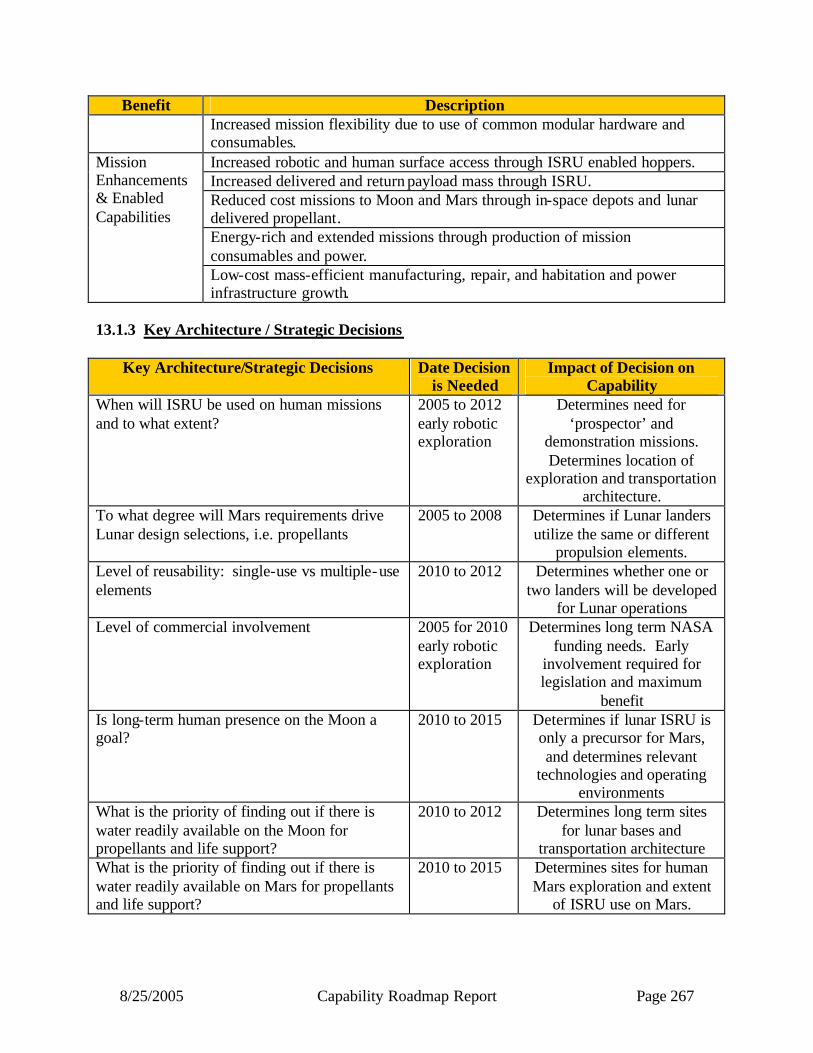
8/25/2005 Capability Roadmap Report Page 267
Benefit Description Increased mission flexibility due to use of common modular hardware and
consumables. Increased robotic and human surface access through ISRU enabled hoppers. Increased delivered and return payload mass through ISRU. Reduced cost missions to Moon and Mars through in-space depots and lunar delivered propellant. Energy-rich and extended missions through production of mission consumables and power.
Mission Enhancements & Enabled Capabilities
Low-cost mass-efficient manufacturing, repair, and habitation and power infrastructure growth.
13.1.3 Key Architecture / Strategic Decisions
Key Architecture/Strategic Decisions Date Decision is Needed
Impact of Decision on Capability
When will ISRU be used on human missions and to what extent?
2005 to 2012 early robotic exploration
Determines need for ‘prospector’ and
demonstration missions. Determines location of
exploration and transportation architecture.
To what degree will Mars requirements drive Lunar design selections, i.e. propellants
2005 to 2008 Determines if Lunar landers utilize the same or different
propulsion elements. Level of reusability: single-use vs multiple-use elements
2010 to 2012 Determines whether one or two landers will be developed
for Lunar operations Level of commercial involvement 2005 for 2010
early robotic exploration
Determines long term NASA funding needs. Early
involvement required for legislation and maximum
benefit Is long-term human presence on the Moon a goal?
2010 to 2015 Determines if lunar ISRU is only a precursor for Mars, and determines relevant
technologies and operating environments
What is the priority of finding out if there is water readily available on the Moon for propellants and life support?
2010 to 2012 Determines long term sites for lunar bases and
transportation architecture What is the priority of finding out if there is water readily available on Mars for propellants and life support?
2010 to 2015 Determines sites for human Mars exploration and extent
of ISRU use on Mars.
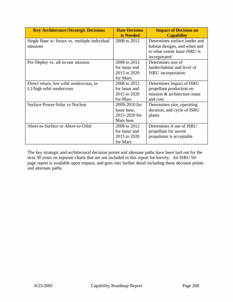
8/25/2005 Capability Roadmap Report Page 268
Key Architecture /Strategic Decisions Date Decision is Needed
Impact of Decision on Capability
Single Base w/ forays vs. multiple individual missions
2008 to 2012 Determines surface lander and habitat designs, and when and to what extent lunar ISRU is incorporated
Pre-Deploy vs. all- in-one mission 2008 to 2012 for lunar and 2015 to 2020 for Mars
Determines size of lander/habitat and level of ISRU incorporation
Direct return, low orbit rendezvous, or L1/high orbit rendezvous
2008 to 2012 for lunar and 2015 to 2020 for Mars
Determines impact of ISRU propellant production on mission & architecture mass and cost.
Surface Power-Solar vs Nuclear
2009-2010 for lunar base, 2015-2020 for Mars base
Determines size, operating duration, and cycle of ISRU plants
Abort-to-Surface or Abort-to-Orbit
2008 to 2012 for lunar and 2015 to 2020 for Mars
Determines if use of ISRU propellant for ascent propulsion is acceptable
The key strategic and architectural decision points and alternate paths have been laid out for the next 30 years on separate charts that are not included in this report for brevity. An ISRU 50-page report is available upon request, and goes into further detail including these decision points and alternate paths.

8/25/2005 Capability Roadmap Report Page 269
13.1.4 Major Technical Challenges The Technical Challenges are based on examining the challenges associated with the Key Capabilities & Sub-Capabilities, and identifying those items that have the biggest potential impact on ISRU plant/element design, performance, maintenance, and/or mission and architecture benefit.
2006-2010 § Lunar dust mitigation § Operation in permanently shadowed lunar crater (40K) § Regolith excavation in harsh/abrasive environments 2010 - 2015 § Large scale oxygen extraction from regolith § Autonomous, integrated operation and failure recovery of end-to-end ISRU
concepts, including resource excavation, transportation, processing, and storage and distribution of products
§ Day/night operation (startup/shutdowns) without continuous power § Efficient water extraction processes § Modular, mass-efficient manufacturing and initial construction techniques
2020 and Beyond
§ Long duration operations with little/no maintenance (300+ sols on Mars) § Habitat and large-scale power system construction techniques

8/25/2005 Capability Roadmap Report Page 270
13.1.5 Key Capabilities and Status The Key Capability table below for ISRU was compiled after a multi-step process. First, past ISRU technology and mission studies and reports were examined to identify ISRU capabilities and quantify the benefits of these capabilities to extending or enabling individual missions and complete architectures. Then the identified capabilities were compared to each other to determine relative ranking. The capabilities/sub-capabilities listed in the table were those that were identified as supporting multiple ISRU capabilities (ex. Excavation and Surface Cryogenic Fluid Storage), that are applicable to both the Moon and Mars, or are critical for achieving significant mass, cost, and/or risk reduction benefits for individual missions or architectures as a whole. Specifically, one of the top priorities for ISRU is determining the availability of potential water resources on the Moon and Mars. From Viking soil and Mars Odyssey data, water may be available all across the Mars surface at various depths and concentrations. From Clementine and Lunar Prospector data, water may be present in the permanently shadowed craters of the Moon. Having a source of readily available water could provide both oxidizer and fuel for propulsion and fuel cell power systems, and can define the degree of self sufficiency, radiation shielding, and closed- loop life support required to sustain humans in space. If water is not available on the Moon, oxygen extraction from the regolith (which contains up to 50% oxygen) can be performed. This capability also supports non-polar Lunar human mission concepts. On Mars, if extraction of water from surface regolith is not practical, then oxygen alone can be produced from the Mars atmosphere, or both oxygen and fuel can be produced from the Mars atmosphere and hydrogen feedstock brought from Earth (Mars Reference Mission). Other ISRU capability priorities include surface construction techniques for dust, debris, and radiation mitigation, in-situ fabrication by metal and silicon extraction from regolith, and in-situ solar power production and storage to enable a power-rich environment.

8/25/2005 Capability Roadmap Report Page 271
Table 13.4 - Key Capabilities
Capability/Sub - Capability
Mission or Roadmap Enabled
Current State of Practice
Minimum Estimated Development Time
(years)
Lunar/Mars Regolith Excavation & Transportation
All Lunar ISRU and Mars water, mineral extraction, & construction ISRU.
Apollo and Viking experience and Phoenix in 2007. Extensive terrestrial experience
5-8 years
2010 (demo) 2017 (pilot)
Lunar Oxygen Production From Regolith
Sustained Lunar presence and economical cis-Lunar transportation
Earth laboratory concept experiments; TRL 2/3
5-8 years 2012 (demo) 2017 (pilot)
Capability/Sub-Capability
Mission or Roadmap Enabled
Current State of Practice
Minimum Estimated Development Time
(years) Lunar Polar
Water/Hydrogen Extraction From
Regolith
Sustained Lunar presence and
economical cis-Lunar
transportation
Study & development just initiated in ICP/BAA
5-6 years 2010 (demo) 2017 (pilot)
Mars Water Extraction From
Regolith
Propellant and life support consumable
production w/o Earth feedstock
Viking experience 5-8 years 2013 (demo) 2018 or 2022
(subscale) Mars
Atmosphere Collection & Separation
Life support and mission
consumable production
Earth laboratory & Mars environment simulation; TRL
4/5
5-8 years 2011 (demo) 2018 or 2022
(subscale) Mars
Oxygen/Propellant Production
Small landers, hoppers, and fuel
cell reactant generation on Mars
Earth laboratory & Mars environment simulation; TRL
4/5
5-8 years 2011 (demo) 2018 or 2022
(subscale) Metal/Silicon
Extraction From Regolith
Large scale in-situ manufacturing and
in-situ power systems
Byproduct of Lunar oxygen experiments; TRL 2/3
10-11 years 2018 (demo)
2022 (pilot scale)
In-Situ Surface Manufacture &
Repair
Reduced logistics needs, low mission risk, and outpost
growth
Terrestrial additive, subtractive, and formative techniques
8-9 years 2010 to 2014 (ISS
demos) 2020 (pilot scale)
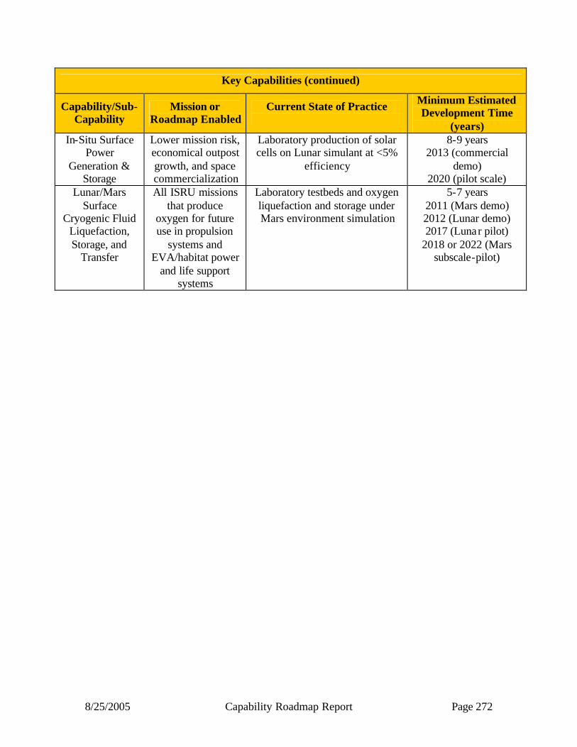
8/25/2005 Capability Roadmap Report Page 272
Key Capabilities (continued)
Capability/Sub-Capability
Mission or Roadmap Enabled
Current State of Practice
Minimum Estimated Development Time
(years) In-Situ Surface
Power Generation &
Storage
Lower mission risk, economical outpost growth, and space commercialization
Laboratory production of solar cells on Lunar simulant at <5%
efficiency
8-9 years 2013 (commercial
demo) 2020 (pilot scale)
Lunar/Mars Surface
Cryogenic Fluid Liquefaction, Storage, and
Transfer
All ISRU missions that produce
oxygen for future use in propulsion
systems and EVA/habitat power
and life support systems
Laboratory testbeds and oxygen liquefaction and storage under Mars environment simulation
5-7 years 2011 (Mars demo) 2012 (Lunar demo) 2017 (Lunar pilot)
2018 or 2022 (Mars subscale-pilot)

8/25/2005 Capability Roadmap Report Page 273
13.2 Roadmap Development 13.2.1 Legacy Activities and Roadmap Assumptions 13.2.2 Reference Relevant Legacy Activities
Between 1986 and 1991, a number of prestigious studies were performed which highlighted the benefits of developing ISRU for use in the future human exploration and development of our solar system [Beyond Earth’s Boundaries, Report of the 90 Day Study on Human Exploration of the Moon and Mars, Report of the Advisory Committee on the Future of the U.S. Space Program, America At the Threshold, etc.]. Since the early ‘90’s, NASA, industry, and academia have performed a number of mission studies which have evaluated the impacts and benefits of ISRU. Results from a study comparing a Lunar architecture which emphasized early production and utilization of Lunar propellants (LUNOX study) versus a conventional Lunar exploration scheme (First Lunar Outpost study) indicated lower hardware development costs, lower cost uncertainties, and a ~50% reduction in human transportation costs for the ISRU-based mission architecture[20]. For Mars, sample return missions with in-situ propellant production as well as the human Mars Reference Mission[2,10,11] studies showed that ISRU could reduce Earth launch mass by >25%. More recent ly, the use of mission staging points for future human Lunar exploration missions shows increased mission flexibility and reduced mission mass are possible with use of Lunar in-situ produced propellants[17,18]. The recent Capability Roadmap activity has been the most intensive and complete to date for ISRU, however, much of the initial work was based on previous strategic planning and road-mapping activities performed for Technology for Human/Robotic Exploration And Development of Space (THREADS), Advanced Systems, Technology, Research, and Analysis (ASTRA), and the Capability Requirements, Analysis, and Integration (CRAI) programs.
13.2.3 Architectural Assumptions
The primary difficulty in executing the Capability Roadmap activity was the lack of defined mission objectives, goals, and dates for the robotic and human exploration of the Moon and Mars. Before the presentation to the National Research Council, the ISRU Capability Roadmap Team created its own ‘notional’ ISRU-Emphasized architecture to highlight potential ISRU-based missions and their logical sequence of events. This architecture was purposefully all-inclusive to ensure all options were captured. For this final report, the NASA APIO provided top-level mission objectives and dates. However, some additional missions have been added to this roadmap to provide a more logical and reduced risk implementation of ISRU into human Lunar and Mars missions. It is believed that these additional missions are consistent with the goals and objectives of current Lunar mission architecture options being considered by the Lunar Strategic Roadmap (Option C Early Lunar Resources) and the Mars Strategic Roadmap teams.
To develop the notional ISRU-Emphasized architecture and estimates of size and power for potential ISRU capabilities, the following architecture attributes were assumed:
§ No Earth launch vehicle assumption was made; benefits were based on reduction in LEO payload

8/25/2005 Capability Roadmap Report Page 274
§ Crew of 4 or 6 assumed up to permanent presence; TBD (12) at permanent presence § Need to characterize resource, surface environment, and engineering unknowns as early as
possible § Utilize ISS for ISRU-related research if available and logical § Develop single robust primary Lunar exploration site(e.g. McMurdo Station approach) after
limited number of initial checkout flights § Demonstrate ISRU in Lunar Sortie and Investigation phase to support use of ISRU and
reusable systems at the start of Central Base operations § Develop Lunar infrastructure and operations to enable sustainable Lunar operations in
parallel with a Mars exploration program In addition to these mission/architecture assumptions, derivatives of the notional ISRU- Emphasized architecture were evaluated including:
§ Direct Return – ISRU Architecture § Earth-Moon L1 propellant for Moon/Mars § ISRU-Commercial Architecture Aimed At All Government & Commercial Applications Below is the latest notional ISRU-Emphasized architecture with start dates for initial ISRU capabilities identified.
Figure 13.1
Architecture & ISRU Capability Timeline
Polar H2 Mapping to 5 km
Ground Truth of Polar H2 Source
Mars ISRU science hopper capability
Mars atmosphere propellant production & storage
demonstrated
Subscale lunar regolith excavation & O2 production & storage
Validation of in-situ solar electricity production
Subscale Mars regolithexcavation & H 2O extraction
Mars subscale human propellant production & storage capability
Lunar O2 Pilot Plant Capability
Mars deep drilling capability Propellant, fuel cell, & life
support production for Mars
Lunar ISRU robotic & human hopper capability
0-g ISRU processing capability
Part fabrication & infrastructure construction (power, habitat, etc.) capability demonstrated
Propellant production & delivery for surface access & Cis-Lunar transportation

8/25/2005 Capability Roadmap Report Page 275
13.2.3.1 Incorporation Strategy The ability to harness and utilize space resources to create products and services requires extra hardware and power but less volume and lift-off mass when compared to missions that bring everything from Earth. It is critical that early missions require the minimum of pre-deployed or delivered hardware and power infrastructure while providing immediate mass and cost benefits. To minimize the cost and risk of incorporating ISRU into missions, an evolutionary approach in technology and scale is assumed. Each design/demonstration activity needs to build on lessons learned from previous work and show clear benefit metrics. Early hardware needs to be achievable (not optimized) and scalable to future missions and base growth. Also, until mission planners have confidence in ISRU, technologies and capabilities may need to be flight tested on robotic precursor missions or pre-deployed before insertion into the critical path for human missions. Once a central exploration base is selected, ISRU incorporated into missions must ensure a constant delivery of products, with incremental growth in both number of products and quantity of products. Capability elements need to be sized based on long-term mission objectives to allow incremental growth through delivery of extra elements or in-situ production with the growth and expansion of surface activities. Surface construction and manufacturing will start with simple/high leverage products and expand to greater self-sufficiency capabilities. 13.2.3.2 Objectives of Lunar ISRU There are three primary objectives for Lunar ISRU: (1) Identify and characterize resources on the Moon, especially the polar region; (2) Perform early demonstrations of ISRU on the Moon in preparation for human exploration of Mars; and (3) Develop and evolve Lunar ISRU capabilities to support sustained, economical human space transportation and presence on the Moon.
For preparation for human exploration of Mars, one main goal for early Lunar robotic and human ISRU missions is to demonstrate concepts, technologies, & hardware that can reduce the mass, cost, & risk of human Mars missions as early as possible. These include: (a) Excavation and material handling & transport, (b) Oxygen production and volatile/hydrogen/water extraction, (c) Thermal/chemical processing subsystems, and (d) Surface cryogenic fluid storage & transfer. Tests of these items on the Moon would provide evaluation of hardware under realistic environmental conditions not possible on Earth, but potentially at a lower cost than Mars missions. Since these concepts, technologies, and hardware are applicable to both the Moon and Mars, early demonstrations also supports sustained human presence on the Moon. The second major objective of early Lunar ISRU demonstrations is to obtain operational experience and mission validation for future Mars missions. Areas of particular importance for experience and mission validation include: (a) Pre-deployment & activation of ISRU assets, (b) Making and transferring mission consumables, such as propellants, life support, power reactants, etc., (c) Landing crew with pre-positioned return vehicle or ‘empty’ tanks, and (d) ‘Short’ (<90 days) and ‘Long’ (300 to 500 days) Mars surface stay dress rehearsals including part manufacturing and construction. Experience with pre-deployment and activation of ISRU is critical for Mars ISRU and the ability of astronauts to evaluate operations, correct early failures, and potentially return
8/25/2005 Capability Roadmap Report Page 276
hardware to Earth for evaluation makes demonstrations on the Moon extremely attractive. The making and transferring of mission consumables and landing near pre-positioned ISRU with empty tanks are critical demonstrations in providing the confidence needed by mission planners to incorporate ISRU early in human Mars missions. These capabilities are essential in achieving the maximum benefits of ISRU.
To support sustained human presence on the Moon, it is essential to develop and evolve Lunar ISRU capabilities that enable new exploration capabilities, such as long-range surface mobility, global science access, power-rich distributed systems, enhanced radiation shielding, etc. For this to be economical and allow continued presence on the Moon while going on to Mars, a space transportation system based on ISRU, reusable transportation assets, and single stage lander/ascent vehicles is required. Further cost benefits to NASA can be achieved if government-commercial space commercialization initiatives are started as soon as possible. 13.2.3.3 Objectives of Mars ISRU There are three primary objectives for Mars ISRU: (1) Perform initial research and development of ISRU and characterize resources on Mars, especially water, in preparation for human exploration; (2) Develop and evolve Mars ISRU capabilities to reduce the cost, mass, and risk of human Mars exploration and enable new missions, (3) Enable human exploration beyond Mars.
For preparation for human exploration of Mars, Earth-based, ISS, and Lunar ISRU development, testing, and experience must be utilized to the maximum extent possible. Also, characterizing the presence and extraction of Mars water as early as possible is critical, since both the benefits and risks are much greater compared to atmospheric processing alone for in-situ consumable production.
Until mission planners are confident in ISRU, demonstrations are recommended in a step-wise approach to increase confidence in environment/resource understanding and reduce mission application uncertainties. Also, ISRU capabilities that enable new exploration options, such as reduced size lander/ascent vehicles, surface mobility and hoppers, power-rich distributed systems, enhanced radiation shielding, manufacturing/construction, etc. should be pursued in an evolutionary approach. Early demonstrations are required due to long experiment development time (~4 years), the 26 month gap between mission launch window opportunities, long trip times, and extended surface operations. Lessons learned from one mission can only influence missions 2 or 3 opportunities (4 or 6 years) later. Because of this, parallel investigations of atmospheric and regolith/water-based processing with convergence to an end to end ISRU demonstration before a human mission is recommended.
It should be noted that every effort should be made to synergize future science and human precursor missions, especially with respect to ISRU. Small demonstrations (20 to 30 kg) on early SCOUT missions can provide immediate Mars ISRU design and operation experience (2011 or 13), and later Human Precursor ISRU missions can provide expended or enabled science objectives (2018 and/or 2022).
Mars ISRU may also be critical to enable human exploration beyond Mars. Use of propellant production from Phobos/Deimos, or re-supply of propellants at a Mars-Sun L1 depot from Mars,

8/25/2005 Capability Roadmap Report Page 277
may provide the logistics needed for long-term human exploration of the asteroid belt and beyond. 13.2.4 Capability Breakdown Structure

8/25/2005 Capability Roadmap Report Page 278
Capability Breakdown Structure
Resource Extraction
13.1Lead: L. Gertch/UMR & Don Rapp/JPL
ResourceAssessment
13.1.1
13.1.2
ResourceAcquisition
ResourceBeneficiation
13.1.3
13.1.4
Site Management
Lead: Kurt Sacksteder/GRC & Dale Boucher/NORCAT
Fixed SiteTransportation
13.2.1
13.2.2
Mobile MaterialTransportation
PayloadMaterial Handling
13.2.3
Lead: Bill Larson/KSC & Larry Clark/LMCO
Mission ConsumableProduction (Life Support
& Propellant)13.3.1
13.3.2
Feedstock Production for in-Situ
Manufacturing
Feedstock Production for Surface Construction
13.3.3
13.3.4
Common CriticalComponents
Lead: Peter Curreri/MSFC & Ed McCullough/Boeing
Additive ManufacturingTechniques
13.4.1
13.4.2
SubtractiveManufacturingTechnologies
FormativeManufacturingTechnologies
13.4.3
13.4.4
Locally IntegratedEnergy Systems
Lead: Kris Romig/JSC & Eric Rice/Orbitec
Site Planning
13.5.1
13.5.2
Surface & SubsurfacePreparation
Structure/HabitatFabrication
13.5.3
13.5.4
Radiation & MicroMeteoroid Debris
Shielding
Lead: Robert Johnson/KSC & Robert Zubrin/Pioneer Ast.
Surface Cryogenic Fluid& Propellant Storage
& Distribution13.6.1
13.6.2
Chemical ReagentStorage & Distribution
Gas Storage &Distribution
13.6.3
13.6.4
Water & Earth StorableFluid Storages
Distribution
Lead: Diane Linne/GRC & Mike Downey/JSC
Modeling &Standards
13.7.1
13.7.2
Simulants
Unique TestEnvironments (1-g)
13.7.3
13.7.4
Reduced GravityTest Environments
13.2 13.3 13.4 13.5 13.6 13.7
Material Handling& Transportation
ResourceProcessing
Surface Manufacturingwith In-Situ Resources
SurfaceConstruction
Surface ISRU Product &Consumable Storage
and Distribution
ISRU UniqueDevelopment &
Certification Capabilities
Locally IntegratedSystems & Components
13.4.5
13.4.6
ManufacturingSupport Systems
Structure & SiteMaintenance
13.5.5
13.5.6
Landing &Launch Site
Utility Connections& Interfaces
13.6.5
13.6.6
Hazard Detection& Suppression
In-Situ Resource Utilization
Chair: Jerry Sanders/JSCCo-Chair: Mike Duke (CSM)
13.1.4
Cross PlatformCapabilities, Reliability
and Logistics
Fig 13.2: In-Situ Resource Utilization (ISRU) Capabilities Breakdown Structure (CBS)

8/25/2005 Capability Roadmap Report Page 279
13.2.5 Roadmap Logic The capability roadmap in this report is a summary level roadmap. This summary level roadmap includes only a roll up of the key sub-capabilities milestone readiness to support a particular mission requirement. Detailed sub-capability and technology roadmaps showing the technology progression and sub-capability development were presented to the NAS and are available in the document sharing system. In the top blue banner of the roadmap, there are those key missions that are pertinent to the roadmap among those derived from the April 15, 2005 interim document delivered by the strategic roadmaps and displayed in the CRM Planning Milestones Chart. The green banner below represents a summary rollup of key capabilities from each of the various capability breakdown structure elements. The peach colored swim-lanes represent the individual top level capability breakdown structure element and the sub-capabilities within this roadmap. The triangles represent the date that the capability is ready to support a given mission, and the diamonds represent decision points.
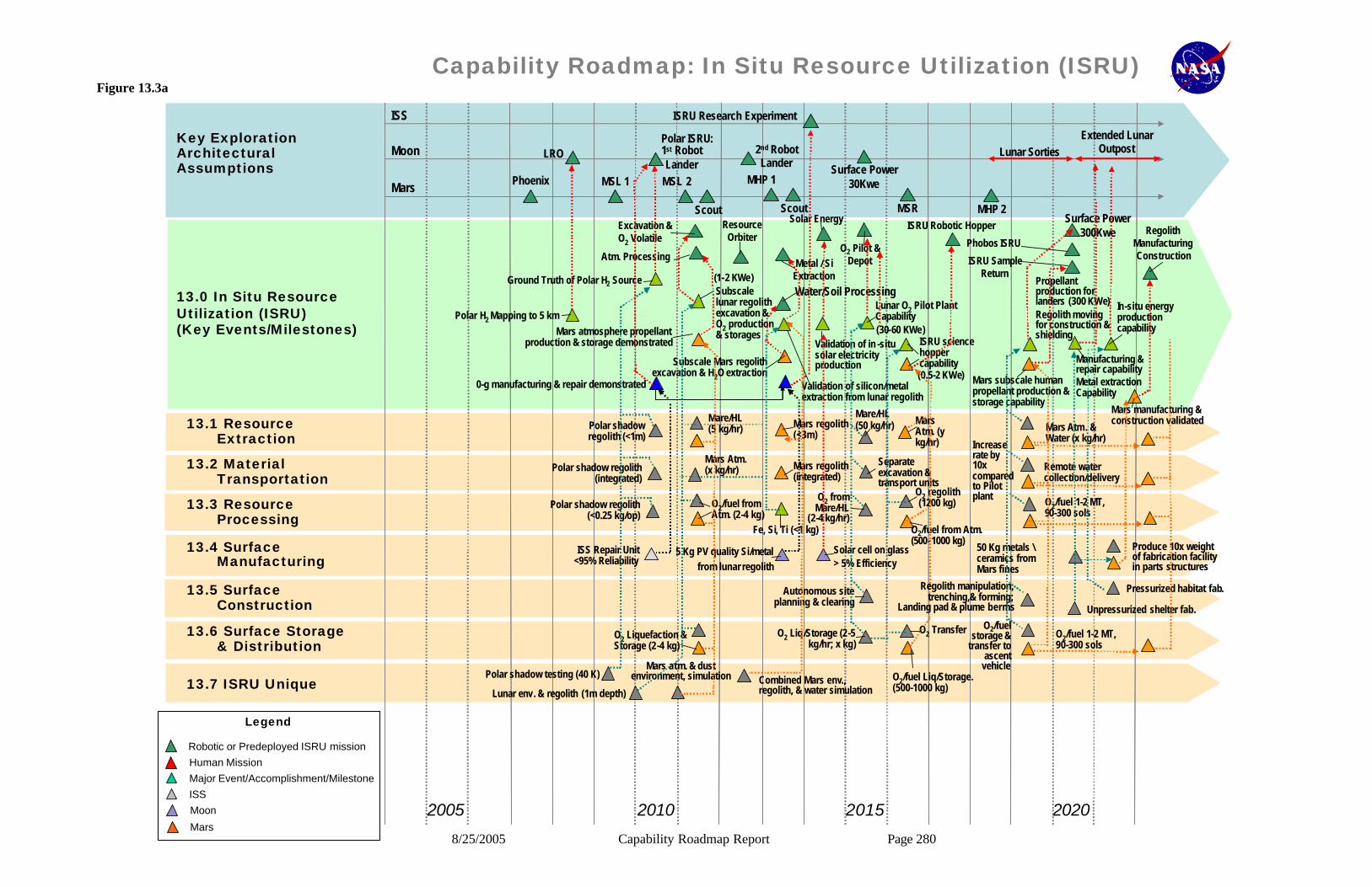
8/25/2005 Capability Roadmap Report Page 280
13.1 Resource Extraction
13.2 Material Transportation
13.3 Resource Processing
13.4 Surface Manufacturing
13.5 Surface Construction
13.6 Surface Storage & Distribution
13.7 ISRU Unique
Capability Roadmap: In Situ Resource Utilization (ISRU)
13.0 In Situ Resource Utilization (ISRU) (Key Events/Milestones)
2005 2010 20202015
Key Exploration Architectural Assumptions
ISS
Moon
Mars
ISS
Robotic or Predeployed ISRU missionHuman MissionMajor Event/Accomplishment/Milestone
Moon
Mars
Phoenix
Excavation & O2 Volatile
Atm. Processing
Resource Orbiter
Solar Energy
Metal / SiExtraction
O2 Pilot & Depot
ISRU Robotic Hopper
MSR
Lunar O2 Pilot Plant Capability(30-60 KWe)
(1-2 KWe)
Polar H2 Mapping to 5 km
Ground Truth of Polar H2 Source
ISRU science hopper capability
Mars atmosphere propellant production & storage demonstrated
Subscale lunar regolithexcavation & O2 production & storages
Validation of silicon/metal extraction from lunar regolith
Validation of in -situ solar electricity production
0-g manufacturing & repair demonstrated
Subscale Mars regolithexcavation & H2O extraction (0.5-2 KWe)
Polar shadow regolith (<1m)
Polar shadow regolith(integrated)
Polar shadow regolith(<0.25 kg/op)
Mare/HL (50 kg/hr)
O2 from Mare/HL
(2-4 kg/hr)
O2 Liq/Storage (2-5 kg/hr; x kg)
Separate excavation & transport units
Polar shadow testing (40 K)
Mare/HL (5 kg/hr)
Mars Atm. (x kg/hr)
O2/fuel from Atm. (2-4 kg)
O2 Liquefaction & Storage (2-4 kg)
O2 Transfer
Mars regolith(<3m)
Autonomous site planning & clearing
Fe, Si, Ti (<1 kg) O2/fuel from Atm. (500-1000 kg)
Mars Atm. (y kg/hr)
O2/fuel Liq/Storage. (500-1000 kg)
Combined Mars env., regolith, & water simulation
Mars atm. & dust environment, simulation
Lunar env. & regolith (1m depth)
Mars regolith(integrated)
O2 regolith(1200 kg)
Solar cell on glass> 5% Efficiency
5 Kg PV quality Si/metalfrom lunar regolith
ISS Repair Unit <95% Reliability
Water/Soil Processing
ISRU Research Experiment
MSL 1 MSL 2
Scout
MHP 1
Scout MHP 2
LROPolar ISRU:1st Robot Lander
2nd Robot Lander
Surface Power 300Kwe
Lunar SortiesExtended Lunar
Outpost
ISRU Sample Return
Mars subscale human propellant production & storage capability
Manufacturing & repair capability Metal extraction Capability
Propellant production for landers (300 KWe)Regolith moving for construction & shielding
In-situ energy production capability
RegolithManufacturing Construction
Mars Atm. & Water (x kg/hr)
Remote water collection/delivery
Regolith manipulation, trenching,& forming;
Landing pad & plume berms
O2/fuel 1-2 MT, 90-300 sols
O2/fuel 1-2 MT, 90-300 sols
O2/fuel storage &
transfer to ascent
vehicle
Increase rate by 10x compared to Pilot plant
Unpressurized shelter fab.
Pressurized habitat fab.
50 Kg metals \ceramics from Mars fines
Produce 10x weight of fabrication facility in parts structures
Mars manufacturing & construction validated
Phobos ISRU
Surface Power 30Kwe
Legend
Figure 13.3a

8/25/2005 Capability Roadmap Report Page 281
13.1 Resource Extraction
13.2 Material Transportation
13.3 Resource Processing
13.4 Surface Manufacturing
13.5 Surface Construction
13.6 Surface Storage & Distribution
13.7 ISRU Unique
Capability Roadmap: In Situ Resource Utilization (ISRU)
13.0 In Situ Resource Utilization (ISRU) (Key Events/Milestones)
2020 2025 20352030
Key Exploration Architectural Assumptions
ISS
Moon
Mars
Extended Lunar Outpost
ISRU Sample Return
Manufacturing & repair capability Metal extraction Capability
In-situ energy production capability
RegolithManufacturing Construction
Mars Atm. & Water (x kg/hr)
Remote water collection/delivery
O2/fuel 1-2 MT, 90-300 sols
O2/fuel 1-2 MT, 90-300 sols
Unpressurized shelter fab.
Pressurized habitat fab.
Produce 10x weight of fabrication facility in parts structures
Mars manufacturing & construction validated
Propellant production for landers (300 KWe)Regolith moving for construction & shielding
1st Mars Human Mission
Surface Power 100Kwe
O2/fuel >30 MT, >300 sols
O2/fuel >30MT, >300 sols
Drill (1-3 km) w/ hole stabilization
> 50 KW In Situ Power at or beamed to Mars base
Mars Human scale consumable production capability
Mars deep drilling capability
Mars in-situ bio support capability validated
Propellant, fuel cell, & life support production for Mars(30-60 KWe)
(4-6 KWe)
NEO ISRU
Deep Drill for Water
Bio-Soil Processing Exp
Construction & Plant Growth
ISS
Robotic or Predeployed ISRU missionHuman MissionMajor Event/Accomplishment/Milestone
Moon
Mars
Legend
ISS
Robotic or Predeployed ISRU missionHuman MissionMajor Event/Accomplishment/Milestone
Moon
Mars
Legend
Figure 13.3b

8/25/2005 Capability Roadmap Report Page 282
13.2.6 Capabilities Assessment As part of the Capability Roadmapping activity, teams were formed to examine the capabilities and technologies of each ISRU Element (see Capability Breakdown Structure (CBS)) in detail. Below is a top- level summary of this evaluation by ISRU Element. More information can be found in the ISRU Final Report and in the ISRU Roadmap Team presentation to the National Research Council (NRC) presented on April 12, 2005. 13.2.6.1 Resource Extraction § Some sub-capabilities have been demonstrated, including scooping of regolith samples on the
Moon and Mars, coring of regolith samples on the Moon, and grinding and analysis of rock samples on the Moon and Mars.
Significant work has been performed on acquiring and separating Mars atmospheric resources. Only preliminary work has been performed on separation/filtration of dust during Mars atmospheric processing and only at very low processing rates. 13.2.6.2 Material Handling & Transportation § Extra-terrestrial experience in handling and transporting native materials is very limited for
Moon (Apollo samples were manually manipulated for encapsulation and were transported in small containers aboard the Lunar rover vehicle and back to Earth) and Mars (samples were/are robotically manipulated for limited analysis and disposal by Viking, MER, etc).
§ Terrestrial experience in material handling is ubiquitous, but translating these capabilities to the ISRU mission is outside existing knowledge.
13.2.6.3 Resource Processing § Lunar ISRU has a 30 year history of laboratory testing, but with little funding for systems
level development. The successful demonstration of oxygen production from actual Lunar soils has already been demonstrated using hydrogen reduction of bulk, unprocessed soils as well as ground Lunar basalt [21,22,23]. All of this work has been at the laboratory scale so the Capability Readiness Level (CRL) is a 2 at best. Most of the candidate technologies are in the TRL 3 to 4 range with a research and development degree of difficulty (RD3) level nominally a II.
§ Mars ISRU has had more development over the last decade but the focus has been atmospheric processing. Several prototype systems have been constructed for oxygen and oxygen/methane production, and the TRL of the technology is 4/5, the CRL is 3, and the RD3 level is I. Laboratory demonstrations have also been performed for other hydrocarbon fuels; methanol, ethylene, benzene/toluene, and short-chain hydrocarbon mixtures (TRL 3/4).
§ A significant number of feedstocks can be derived from the Lunar and Martian Regolith. The moon is rich in metals (Fe, Al, Ti, Si) and glasses that can be spun into fibers. Viking data indicates the same metals are available in the Martian regolith suggesting that many of
8/25/2005 Capability Roadmap Report Page 283
the metal production technologies may be applicable to both the Moon and Mars. Many of the regolith oxygen production technologies leave behind pure metals in their wake. This has been demonstrated at the laboratory scale (TRL 3 or 4). However, none of the laboratory experiments actually separated the pure metals out from the remaining slag. So the CRL for the production of metals is at best a 2.
13.2.6.4 Surface Manufacturing with In-Situ Resources § Extensive microgravity materials processing experiments have been done in space in Apollo,
Skylab, and Spacelab. § Paper studies show that 90% manufacturing materials closure can be obtained from Lunar
materials and 100% from Mars materials. § Feasibility efforts for fabrication of photovoltaic cells and arrays out of Lunar derived
materials have been performed. 13.2.6.5 Surface Construction § Site planning: Lunar/Mars topography data sets are partially available, some geophysical
characterization is available (Apollo/Mars programs), and Lunar regolith and properties for upper 2 meters is available from the Apollo program.
§ Structure & Habitat Fabrication: Many in situ-based or derived habitat construction methods have well-characterized terrestrial equivalents, and laboratory tests have been performed on Lunar construction materials ( waterless concretes, glass fibers and rods, sintered bricks, etc.)
§ Radiation protection: Micro-Meteoroid Debris (MMOD) concepts and hardware design for ISS currently exist (Aluminum/Kevlar/Nextel) and advanced shields were under development during the TransHab project.
§ Structure & Site Maintenance: In space maintenance and repair are evolving, self-healing materials are currently being tested , EVA and IVA repairs are regularly performed on the International Space Station, and tile repair tools and materials are being developed as part of return to flight activities for the Space Shuttle.
§ Landing & Launch Site: Apollo style landings on the Moon showed ejecta occurred but did not threaten the Lunar Excursion Module (LEM) which was ~18 MT. Since the current designs for Lunar landers are a minimum of 28 metric tons (MT), effects of larger vehicle landings need to be studied and mitigation strategies designed if significant cratering is anticipated so that multiple landings can be accomplished at the same site.
13.2.6.6 Surface ISRU Product and Consumable Storage and Distribution § Limited size and capacity cryo-coolers have flown (science instruments). § Cryogenic fluid storage systems have flown, but for limited durations and not with integrated
liquefaction systems. § Automatic and EVA fluid couplings have flown on ISS; Helium II coupling built but not
flown.

8/25/2005 Capability Roadmap Report Page 284
13.2.7 Relationship to Other Roadmaps (capability and strategic) 13.2.7.1 Interdependency with Surface Power Because many ISRU processes are power intensive, the power density of stationary and mobile power systems is important when considering the total benefits and impacts of ISRU on missions and architectures. If ISRU capabilities can be pre-positioned before crew arrive, the same surface power systems can be used later for crew/habitat use, thereby reducing total power infrastructure needs. At the same time, through in-situ production of fuel cell reactants, solar energy generation and storage units, and power management, control, and distribution, ISRU can provide long-term products for a power-rich environment and surface power infrastructure growth. The need date for surface nuclear power is highly linked to the start date for large scale ISRU production. 13.2.7.2 Interdependency with Propulsion The production of oxygen for propulsion systems is possible on both the Moon and Mars, however, until more is learned about the hydrogen source and potential resources that may be found at the Lunar poles from Clementine and Lunar Prospector data (hydrogen, water, ammonia or hydrocarbons), it is not known at this time if there is a common in-situ production fuel for both the Moon and Mars. Because Mars is rich in readily available carbon (and potentially water), a number of in-situ produced hydrocarbon fuels are possible. The simplest is methane, however production of methanol, ethylene, benzene/toluene, and short-chain hydrocarbon mixtures have been demonstrated in the laboratory. A risk-benefit study should be performed to assess the benefits-complexity of the fuel choice on both the propulsion system and ISRU plant. In the roadmapping activity, it was assumed that ISRU would provide surface propellant depots and transfer capabilities to lander/ascent and hopper vehicles. 13.2.7.3 Interdependency with Surface Mobility Surface mobility assets are critical for the success of ISRU based on the need to excavate and transport large amounts of regolith on the Moon, and potentially on Mars for water extraction. In the roadmapping activity, it was assumed that Surface Mobility assets for ISRU excavation and transport would be provided by the Human Exploration Systems & Mobility capability. ISRU would provide its own unique excavation and material handling & transportation units if required. Effort should be made to make crew transport and ISRU surface mobility assets as modular and common as possible to reduce development and launch costs. 13.2.7.4 Interdependency with Human Support Systems Even though ISRU will most likely operate autonomously before crew arrival with the minimum of maintenance required, there are critical relationships between ISRU and Human Support Systems. In the roadmapping activity, it was assumed that ISRU would provide backup life support consumable production, storage, and distribution for Human Health & Support Systems. It was also assumed that ISRU would provide any manufacturing and construction requiring use

8/25/2005 Capability Roadmap Report Page 285
or manipulation of local materials, while habitat and surface asset construction through assembly of pre-built units delivered from Earth would be provided by Human Health & Support Systems. 13.2.8 Infrastructure Assessment 13.2.8.1 Critical facilities or other physical infrastructure needed to execute this roadmap Conditions on the moon include high vacuum, large temperature variations during the lunar day, low temperatures during the lunar night and at the poles, reduced gravity, and highly abrasive dirt environment. 20 percent (by mass) of the Apollo returned samples were less than 20 microns. While conditions on Mars do not include the high vacuum, they do include wide temperature variations dependent on day/night and winter/summer cycles and on latitude. The Mars atmosphere also introduces dust storms at up to 95 m/s (300 km/hr). The table below lists the relevant conditions on the surface of the moon and Mars. Table 13.2 Mars and Lunar Surface Temperatures
Test Simulation Condition
Pressure (torr) Temperature (K)
Wind (km/hr) Gravity (Earth = 1)
Lunar Day 10-10 255 – 390 N/A 1/6 Lunar Night 10-11 120 N/A 1/6 Lunar Poles 10-11 40 N/A 1/6 Mars* 2.25 – 7.5 145 – 240 300 0.38
In addition to these physical conditions, most of the ISRU capabilities will require simulants in the test chambers to demonstrate operation in a relevant environment. While many tests will only require dust simulant to demonstrate that the equipment can operate in the abrasive environment, the excavation, material handling and transport, and surface construction capabilities will require layers of regolith simulant. For excavation tests and development, the regolith will need to be layered up to 2 meters deep with the correct stratification as found on the lunar surface.
In evaluating the ability of existing facilities to properly simulate the lunar surface environment, a note needs to be made concerning the very low pressures on the moon. The best pressure that facilities larger than approximately 1 ft3 can obtain is between 10-6 and 10-8 torr. However, before claiming that hard vacuum simulation is therefore a critical gap, we must evaluate the physical processes that are affected by pressure and determine at what level of vacuum do changes in these physical processes stop occurring. To date, the following five processes have been considered: § Electrical: in a rough vacuum, an electrical spark has a tendency to arc to a wall 20 feet
away instead of a few millimeters away due to the Paschen curve breakdown. This is not an issue beyond approximately 10-3 torr.
§ Heat Transfer: both convection and thermal conductivity (through a gas phase) are functions of gas pressure. Sources indicate that beyond approximately 10-4 torr these are both essentia lly zero.
§ Self-Welding: Two flat, bare metal surfaces have a tendency to stick when brought together, a process referred to as self-welding, cold-welding, or friction welding. Since

8/25/2005 Capability Roadmap Report Page 286
metal surfaces in an atmosphere have an oxide coating which is quickly reformed when stripped away due to rubbing or scraping (and are therefore not ‘bare’ metal), self-welding is not a common problem. However, in a vacuum there will be no reforming of the oxide layer when machinery parts rub together. Unfortunately there are many variables that would affect the process of self-welding (e.g. the load that two parts are placed under) and it is difficult to predict what vacuum level is good enough to test this issue.
§ Bulk Materials: The angle of repose, or heaping behavior, of granular media is affected by the gas pressure. Gas molecules can fill the pores of the grains or even form a coating of molecules on the grain surfaces. Limited two-dimensional tests performed showed that the heap height increased as pressure was lowered below 760 torr (1 atm) until about 100 torr where the height then plunged. Since no data on this phenomena exists below 1 torr, it is difficult to predict at what pressure the behavior levels out. Experts predict insignificant changes by 10-3 or 10-4 torr.
§ Seals: The effect of a hard vacuum on seals was also considered, since sealing in an abrasive environment will be a critical technical challenge. However, since seals respond to a delta pressure, and the pressure on the inside of the seal will be 1 atm or higher, then the seal will behave the same in a coarse vacuum or hard vacuum since the delta pressure is basically the same.
Based on the above physical processes and their affects at low pressures, it appears that existing facilities that can achieve 10-6 to 10-8 torr are sufficient to demonstrate operation in a relevant environment for ISRU technologies and capabilities. 13.2.8.2 Locations of critical facilities or other physical infrastructure exist to execute the
roadmap (within NASA, Industry, Academia, Other Government) The majority of facilities that meet the requirements of lunar and Mars surface simulation exist at NASA or other government sites. One critical issue is whether or not the facility is tolerant (and willing) of introducing simulants (aka dirt) into the vacuum chamber. In general, vacuum chambers that use cryo pumps will be tolerant of dirt, and vacuum chambers that use oil diffusion pumps will not be tolerant.
An attempt was made to survey existing facilities to determine best matches for the requirements listed above. NASA, DoD, and some industry and academia were contacted. Not all responded. Below is a list of some of the applicable facilities identified so far. § Space Power Facility (SPF), NASA GRC’s Plum Brook Station. This is the world’s largest
vacuum facility at 30 m diameter by 33.5 m tall. It has a vacuum pressure of 10-6 torr, and a controllable temperature range of 80 K – 390 K. Its cryo pumps are tolerant of dirt, and the facility has already performed tests with simulated Martian rocks and dust for the Mars Exploration Rover (MER) airbag drop tests.
§ Space Environment Simulation (SES), NASA GSFC. A very large vacuum chamber at 8 by 12 meters, and one of only 4 facilities found with a controllable temperature that can simulate the lunar poles. The chamber cryo pumps should be tolerant to dirt. (Note, the GSFC web site for this facility lists the temperature range as only 93K and 143 K – 373 K, but may not have been updated since the helium refrigerator was recently installed.)
8/25/2005 Capability Roadmap Report Page 287
§ K-Site, NASA GRC. A 7.6 meter chamber with 4 meter diameter cold shroud with excellent pressure (5 x 10⁻⁸ torr) and lunar pole temperatures (20K – 394K). However, its oil diffusion pump would require a filtration system (minor mod) to enable testing with simulants. This facility has a shaker system that allows for vibration and shock testing under thermal-vacuum conditions.
§ Chamber A and Chamber B, NASA JSC. Both have cryo pumps tolerant of dirt, a pressure capability of 10-6 torr, and low temperature (77K). Chamber A is 15 by 27.5 meters and Chamber B is 7.6 by 7.6 meters.
§ 20’ (6 m) Subsystem Altitude, NASA JSC. With a pressure of 10-2 torr and a temperature range of 145 K – 300 K, this facility has already performed tests with a mixture of gases to simulate the Mars atmosphere.
§ Mars Wind Tunnel, NASA Ames. 16 m long with a 1.2 m square test section, this wind tunnel has been used to simulate dust storms on Mars at simulated pressures. It does not have any temperature simulation capability.
§ Zero-G, NASA GRC. The world’s biggest drop tower, it can achieve 10-5 gravity level for 5.2 seconds. Simulants and low pressures can both be achieved inside sealed test chambers.
§ C-9 Aircraft, NASA. By flying parabolic trajectories, this aircraft can achieve various gravity levels: 20 seconds of micro-g, 30 seconds of lunar-g, and 40 seconds of Mars-g per parabola. The total payload bay is 15 m long with a 2.5 by 2 m cross section.
§ DoD AEDC. The Mark I (13 by 25 m) and 10V (3 by 9 m) facilities both have vacuum capabilities in the 10-7 torr level. The 10V lists a lunar polar temperature capability, but it has an extremely high cleanliness rating (100), and it is unlikely that they would be willing to introduce simulants into this chamber. The Mark I lists a temperature range of 77K – 373K, but its high cleanliness rating of 1K also implies an unwillingness to introduce simulants.
8/25/2005 Capability Roadmap Report Page 288
13.2.8.3 Special physical infrastructure planning considerations that the roadmapping
team thinks should be highlighted. Vacuum test chambers that introduce dust and regolith simulants may never be able to regain a high cleanliness rating required for other capability development such as advanced telescopes and observatories and scientific instruments and sensors. The challenge will be to convince certain facilities to become “dirty” facilities with sufficient long-term test possibilities that these “dirty” facilities will not be hurt by the potential loss of test programs that require “clean” facilities.
In addition to vacuum chambers that are tolerant (and willing) of using simulants on a large scale, remote equipment to handle, distribute, and charge simulants within the evacuated vacuum chamber is required. It may be necessary to create and maintain simulants in a vacuum environment to avoid saturating with terrestrial constituents.
There is no capability for long-term simulation of reduced gravity, and it is unlikely that one will be built unless a free-flying centrifuge or tethered facility is funded. Currently we must send robotic demos to prove out long-duration reduced gravity capability, and the opportunities for these flights are limited.
Finally, there is no medium-to- large scale integrated test capability that can duplicate the thermal, vacuum, dust, and gravity environment simultaneously.

8/25/2005 Capability Roadmap Report Page 289
References 1. Wittenberg, L., “In-Situ Extraction of Lunar Soil Volatiles”, 4th International Conference on
Space ’94. 2. Hoffman, S. J. and Kaplan, D. I. (editors) (1997) “Human Exploration of Mars: The
Reference Mission Of The NASA Mars Exploration Study Team”, NASA Special Publication 6107. and NASA Technical Memorandum EX13-98-036, “Reference Mission Version 3.0 addendum to the Human Exploration of Mars”, June 1998.
3. Rapp, Donald, & Andringa, Jason, “Design Reference Missions for Human Exploration of Mars”, JPL, 2005
4. Connolly, John and Joosten, B. Kent, “White Paper: Rationale for Mars In Situ Resource Utilization”, Oct. 1, 1996
5. Analysis performed by SN/G. Badhwar and Boeing/B. Atwell. 6. Information found at website: http://www.lpi.usra.edu/expmoon/Apollo12/A12_surfops.html 7. A. Ignatiev and D. Criswell, "Solar Energy from the Moon", Energy &
Nanotechnology Workshop II: Prospects for Solar Energy, Rice University, October 16-17, 2004
8. NAFCOM99 data with 1.16 inflation factor for FY05 costs 9. Zubrin, Robert, “Review of NASA Lunar Program Architecture”, Jan. 10, 2005 10. x. R. Zubrin, D. Baker, and O. Gwynne, "Mars direct: A simple, Robust, and Cost-Effective
Architecture for the Space Exploration initative,"" AIAA 91-0326, 29th Aerospace Sciences Conference, Reno, NV Jan. 1991.
R. Zubrin and D. Weaver, "Practical Methods for Near-Term Piloted Mars Missions," AIAA 93-2089, 29th AIAA/ASME Joint propulsion Conference, Monerey, CA June28-30, 1993. Republished in JBIS July 1995.
11. R. Zubrin and S. Price, "Mars Sample Return mission Utilizing In-Situ Propellant Production," Lockheed Martin Final Report on contract NAS 9-19359, Delivered to NASA JSC March 31, 1995. R. Zubrin "A Comparison of Methods for the Mars Sample Return Mission," JBIS vol 51, pp.116-120, 1998
12. Zubrin, R.M. (1992) The Design of Lunar and Mars Transportation Systems Utilizing Extraterrestrial Resources. IAA Paper No. 92-0161, 43rd Congress of the International Astronautical Federation, Washington, DC.
13. Sanders, Gerald B., (2000), "Space Resources Development – The Link Between Human Exploration And The Long-Term Commercialization Of Space," Space Resources Roundtable II (2000), http://www.lpi.usra.edu/meetings/resource2000/pdf/7039.pdf
14. Foust, Jeff, (2004), "Commercializing the new space initiative," The Space Review, March 1, 2004, http://www.thespacereview.com/article/109/1
15. Dinkin, Sam, (2004), "Property rights and space commercialization," The Space Review, May 10, 2004, http://www.thespacereview.com/article/141/1

8/25/2005 Capability Roadmap Report Page 290
16. Office Of Space Commercialization, Technology Administration, U.S. Department of Commerce, "Market Opportunities in Space: The Near-Term Roadmap," http://www.technology.gov/space/library/workshops/2001-11-07/speakers.shtml
17. Siegried, W., Santa, J., “Use of Propellant From The Moon In Human Exploration Of Space”, MDC 99H1309, Presented at 50th International Astronautical Congress, Amsterdam, The Netherlands, Oct., 1999
18. Rapp, Donald, “Fueling of Mars-Bound Vehicles in LEO with Propellants Derived from Lunar Resources”, Skillstorm, Inc. in affiliation with JPL, April 2005.
19. NASA, JSC, Mars Combo Lander Study, 20, Joosten, B. K., Guerra, L. A., “Early Lunar Resource Utilization: A Key to Human
Exploration”, AIAA 93-4784, AIAA Space Programs and Technologies Conference, Huntsville, AL., Sept. 1993.
21. Allen, C.C., Morris, R.V., and McKay, D.S. (1996) Oxygen extraction from Lunar soils and pyroclastic glass. Journal of Geophysical Research - Planets 101, 26,085-26,095.
22. Allen, C.C., Morris, R.V., and McKay, D.S. (1994) Experimental reduction of Lunar mare soil and volcanic glass. Journal of Geophysical Research - Planets 99, 23,173-23,185.
23. Gibson, M.A., Knudsen, C.W., Brueneman, D.J., Allen, C.C., Kanamori, H., and McKay, D.S. (1994) Reduction of Lunar basalt 70035 - oxygen yield and reaction product analysis. Journal of Geophysical Research - Planets 99, 10,887-10,897.
24. Transportation Systems Data Book (DR-8), John D. Duffy, Program Manager, General Dynamics Space Systems Division, (February, 1993)
25. Delta IV Technical Summary, The Boeing Company (July 2004) 26. S.K. Borowski, L.A. Dudzinski and M.L. McGuire, “Bimodal Nuclear Thermal Rocket
(NTR) Propulsion for Power-Rich, Artificial Gravity Human Exploration Missions to Mars”, IAA-01-IAA.13.3.05, International Astronautical Federation 52nd International Astronautical Congress (October 2001)
27. Stephen J. Hoffman, David L. Kaplan, Editors, Human Exploration of Mars: The Reference Mission of the NASA Mars Exploration Study Team, Johnson Space Center Exploration Office, (June 1997) 28. K. Pauly, “A Comparison of In Situ Resource Utilization Options for the First Human Mars Missions”, Proceedings of the Founding Convention of the Mars Society, Part II, Pgs 681 – 694 (March 1998)
29. R. Zubrin, “The Case for Mars”, Touchstone, 1997, p 5. 30. B. Ruiz, M.B. Duke, “Production of Methane from the Lunar Regolith for use as Propellant”,
Earth and Space 2004 9th Biennial ASCE Conference on Engineering, Construction and Operations in Challenging Environments, pp 828-834, (March 2004) 31. Microgravity Experiments: Walter, H.U., "Fluic Sciences and Materials Science in Space," Springer-Verlahg, New York, 1987.
32. Curreri, P. A. and D. M. Stefanescu, "Low-Gravity Effects During Solidification," Metals Handbook: Ca Vol. 15, 9th edition, pp. 147-158 (American Society of Metals International: Metals Park, Ohio) (1988).
8/25/2005 Capability Roadmap Report Page 291
33. Lab Test for PV production using Lunar Simulant: A. Freundlich, T. Kubricht, and A. Ignatiev: "Lunar Regolith Thin Films: Vacuum Evaporation and Properties," AIP Conf. Proc., Vol. 420, (1998) p. 660
34. Advanced Automation for Space Missions, NASA CP 2255, Proceedings of the 1980 NASA ASEE, Summer Study, Santa Clara California
The ISRU Capability Roadmap team extends special thanks the following individuals who have volunteered their special skills and uncounted hours to make this roadmap and summary possible: Dale Boucher, NORCAT Trygve "Spike" Magelssen, Futron Alex Ignatiev, Univ. Houston Darryl Calkins, Army Cold Regions Reserch & Eng. Lab Klaus P. Heiss, High Frontier Tom Simmons, JSC Ron Schlagheck, Laurent Sibille, Ray French, Julie Ray, & Mark Nall, MSFC

8/25/2005 Capability Roadmap Report Page 292
NASA
Capability Road Map (CRM) 14
Advanced Modeling, Simulation, and Analysis (AMSA)
Executive Summary
Chair: Erik Antonsson, Calif Institute of Technology Co-Chair: Tamas Gombosi, University of Michigan
Deputy Chair: Loren Lemmerman, JPL
Coordinators
Directorate
Harley Thronson, NASA SMD Giulio Varsi, NASA SMD
APIO
Jan Aikins, NASA ARC
Team Members
NASA / JPL / LLNL/ NSF/Sandia
Walt Brooks, NASA ARC Tsengdar Lee, NASA GSFC Ricky Rood, NASA GSFC Tom Zang, NASA LaRC
Charles Norton, NASA JPL Dave Bader, LLNL
Steve Mecham, NSF Carl Peterson, Sandia
Academia
Dan Reed, University of North Carolina John Rundle, Univ of California, Davis Quentin Stout, University of Michigan
Industry
Ron Fuchs, Boeing
Karen Fucik, Northup Grumman Mark Gersh, Lockheed-Martin Mike Lieber, Ball Aerospace
Irene Qualters, Merk

8/25/2005 Capability Roadmap Report Page 293
14 Advanced Modeling, Simulation, and Analysis (Roadmap 14) 14.1 General Capability Overview 14.1.1 Capability Description Advanced Modeling, Simulation, and Analysis (AMSA) is pervasively used by NASA (and its contractors and grantees). It is present in every aspect of NASA business, particularly in the technical areas of engineering, operations, and science. Examples in science are model-based animations of natural phenomena like crustal deformation, star formation, and galaxy collisions. In engineering, simulations and analyses of many different types are used to understand physical behavior, from high-speed flow-fields over the space shuttle, to stress concentrations in engineered components, to integrated optical-mechanical- thermal models of space telescopes. In operations, simulations of mission operations are frequently used, such as system reconfigurations and docking operations. AMSA has a firmly established role in NASA’s business. 14.1.2 Capability Benefits The goal of this roadmap is to advocate a much more highly integrated AMSA capability for NASA. This is dictated by the simple realization that programs and systems that are being planned are not amenable to integrated ground testing and verification. As a result, the overriding priority should be to develop an architecture and structure for integration of AMSA capabilities, so that interoperability and communication can be incorporated along with improvements to existing codes. The impact of a highly integrated AMSA capability within NASA will enable exploration of a significantly wider range of alternatives during mission or system development, and to consid-erably better understand performance and risks. Physical testing will never be completely eliminated, but should be reduced to those irreducible tests necessary to validate the simulation results, and to confirm the behavior of the system being developed. As the challenges of space exploration grow, the sophistication of space systems is also growing. This complexity reduces our ability to test such systems on Earth. For example, large deployable structures for observational systems will not be able to be tested in a 1g environment. Highly integrated modeling and simulation provides the key to enable the development, and performance evaluation, of future space systems. A significant problem that has occurred as AMSA capabilities are developed and implemented independent of one another is that NASA doesn’t obtain the full benefit of the AMSA potential. For example, in engineering, the state of the practice of AMSA during mission development is a series of data transfers, in which successive modeling activities must manually import data, develop appropriate mathematical models independently, conduct analyses, and then send the results to yet another related - but disconnected - analysis activity. This has arisen because domain experts, seeking better solutions to their specific problems, developed discipline-centric
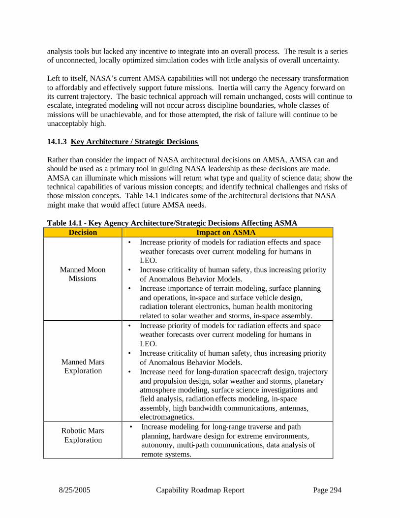
8/25/2005 Capability Roadmap Report Page 294
analysis tools but lacked any incentive to integrate into an overall process. The result is a series of unconnected, locally optimized simulation codes with little analysis of overall uncertainty. Left to itself, NASA’s current AMSA capabilities will not undergo the necessary transformation to affordably and effectively support future missions. Inertia will carry the Agency forward on its current trajectory. The basic technical approach will remain unchanged, costs will continue to escalate, integrated modeling will not occur across discipline boundaries, whole classes of missions will be unachievable, and for those attempted, the risk of failure will continue to be unacceptably high. 14.1.3 Key Architecture / Strategic Decisions Rather than consider the impact of NASA architectural decisions on AMSA, AMSA can and should be used as a primary tool in guiding NASA leadership as these decisions are made. AMSA can illuminate which missions will return what type and quality of science data; show the technical capabilities of various mission concepts; and identify technical challenges and risks of those mission concepts. Table 14.1 indicates some of the architectural decisions that NASA might make that would affect future AMSA needs. Table 14.1 - Key Agency Architecture/Strategic Decisions Affecting ASMA
Decision Impact on ASMA
Manned Moon Missions
• Increase priority of models for radiation effects and space weather forecasts over current modeling for humans in LEO.
• Increase criticality of human safety, thus increasing priority of Anomalous Behavior Models.
• Increase importance of terrain modeling, surface planning and operations, in-space and surface vehicle design, radiation tolerant electronics, human health monitoring related to solar weather and storms, in-space assembly.
Manned Mars Exploration
• Increase priority of models for radiation effects and space weather forecasts over current modeling for humans in LEO.
• Increase criticality of human safety, thus increasing priority of Anomalous Behavior Models.
• Increase need for long-duration spacecraft design, trajectory and propulsion design, solar weather and storms, planetary atmosphere modeling, surface science investigations and field analysis, radiation effects modeling, in-space assembly, high bandwidth communications, antennas, electromagnetics.
Robotic Mars Exploration
• Increase modeling for long-range traverse and path planning, hardware design for extreme environments, autonomy, multi-path communications, data analysis of remote systems.
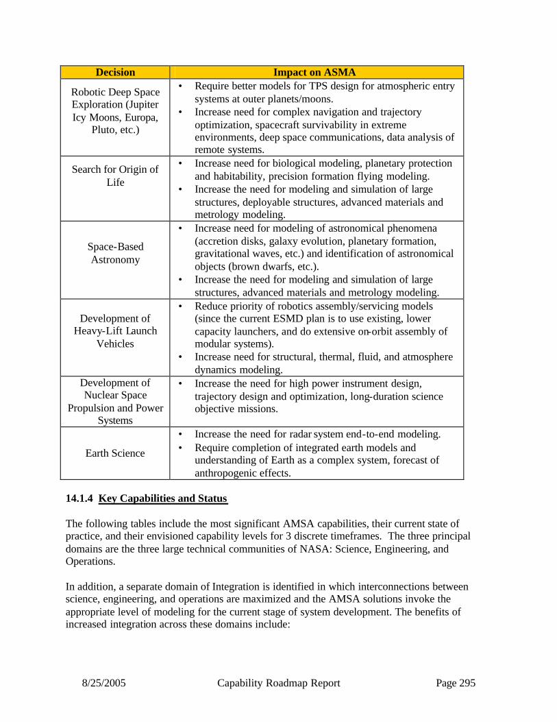
8/25/2005 Capability Roadmap Report Page 295
Decision Impact on ASMA
Robotic Deep Space Exploration (Jupiter Icy Moons, Europa,
Pluto, etc.)
• Require better models for TPS design for atmospheric entry systems at outer planets/moons.
• Increase need for complex navigation and trajectory optimization, spacecraft survivability in extreme environments, deep space communications, data analysis of remote systems.
Search for Origin of Life
• Increase need for biological modeling, planetary protection and habitability, precision formation flying modeling.
• Increase the need for modeling and simulation of large structures, deployable structures, advanced materials and metrology modeling.
Space-Based Astronomy
• Increase need for modeling of astronomical phenomena (accretion disks, galaxy evolution, planetary formation, gravitational waves, etc.) and identification of astronomical objects (brown dwarfs, etc.).
• Increase the need for modeling and simulation of large structures, advanced materials and metrology modeling.
Development of Heavy-Lift Launch
Vehicles
• Reduce priority of robotics assembly/servicing models (since the current ESMD plan is to use existing, lower capacity launchers, and do extensive on-orbit assembly of modular systems).
• Increase need for structural, thermal, fluid, and atmosphere dynamics modeling.
Development of Nuclear Space
Propulsion and Power Systems
• Increase the need for high power instrument design, trajectory design and optimization, long-duration science objective missions.
Earth Science
• Increase the need for radar system end-to-end modeling. • Require completion of integrated earth models and
understanding of Earth as a complex system, forecast of anthropogenic effects.
14.1.4 Key Capabilities and Status The following tables include the most significant AMSA capabilities, their current state of practice, and their envisioned capability levels for 3 discrete timeframes. The three principal domains are the three large technical communities of NASA: Science, Engineering, and Operations. In addition, a separate domain of Integration is identified in which interconnections between science, engineering, and operations are maximized and the AMSA solutions invoke the appropriate level of modeling for the current stage of system development. The benefits of increased integration across these domains include:
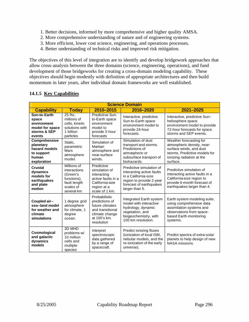
8/25/2005 Capability Roadmap Report Page 296
1. Better decisions, informed by more comprehensive and higher quality AMSA. 2. More comprehensive understanding of nature and of engineering systems. 3. More efficient, lower cost science, engineering, and operations processes. 4. Better understanding of technical risks and improved risk mitigation.
The objectives of this level of integration are to identify and develop bridgework approaches that allow cross-analysis between the three domains (science, engineering, operations), and fund development of those bridgeworks for creating a cross-domain modeling capability. These objectives should begin modestly with definition of appropriate architectures and then build momentum in later years, after individual domain frameworks are well established. 14.1.5 Key Capabilities
Science Domain Capability Today 2010–2015 2016–2020 2021–2025
Sun-to-Earth space environment model for space storms & SEP events
25 Re, millions of cells, kinetic solutions with 1 billion particles
Predictive Sun-to-Earth space environment model to provide 3-hour forecasts
Interactive, predictive Sun-to-Earth space environment model to provide 24-hour forecasts.
Interactive, predictive Sun–heliosphere space environment model to provide 72-hour forecasts for space storms and SEP events.
Comprehensive planetary hazard models to support human exploration
Static, parametric Mars atmosphere model.
Simulation of Martian atmosphere and near-surface winds.
Simulation of dust transport and storms. Predictions of atmospheric or subsurface transport of biohazards.
Weather forecasting for atmospheric density, near-surface winds, and dust storms. Predictive models for ionizing radiation at the surface.
Crustal dynamics models for earthquakes and plate motion
Millions of interactions (Green’s functions), fault length scales of several km
Predictive simulation of interacting active faults in a California-size region at a scale of 1 km.
Predictive simulation of interacting active faults in a California-size region to provide 2-year forecast of earthquakes larger than 5.
Predictive simulation of interacting active faults in a California-size region to provide 6-month forecast of earthquakes larger than 4.
Coupled air–sea–land model for weather and climate simulations
1 degree grid atmosphere for climate, 1 degree ocean.
Probabilistic predictions of future climates and transitional climate change at 100’s km. resolution
Integrated Earth system model with interactive hydrology, dynamic vegetation, and biogeochemistry, with 100 km resolution.
Earth system modeling suite, using comprehensive data assimilation systems and observations from space-based Earth-monitoring systems.
Cosmological and galactic dynamics models
3D MHD problems w/ 10 million cells and multiple species
Interpret spectroscopic data gathered by a range of spacecraft.
Predict ionizing fluxes (ionization of local ISM, nebular models, and the re-ionization of the early universe).
Predict spectra of extra-solar planets to help design of new NASA missions.
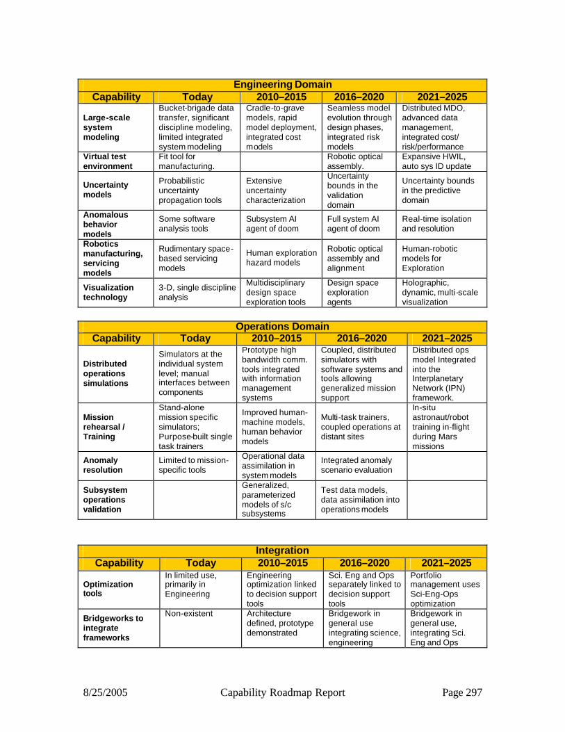
8/25/2005 Capability Roadmap Report Page 297
Engineering Domain
Capability Today 2010–2015 2016–2020 2021–2025
Large-scale system modeling
Bucket-brigade data transfer, significant discipline modeling, limited integrated system modeling
Cradle-to-grave models, rapid model deployment, integrated cost models
Seamless model evolution through design phases, integrated risk models
Distributed MDO, advanced data management, integrated cost/ risk/performance
Virtual test environment
Fit tool for manufacturing.
Robotic optical assembly.
Expansive HWIL, auto sys ID update
Uncertainty models
Probabilistic uncertainty propagation tools
Extensive uncertainty characterization
Uncertainty bounds in the validation domain
Uncertainty bounds in the predictive domain
Anomalous behavior models
Some software analysis tools
Subsystem AI agent of doom
Full system AI agent of doom
Real-time isolation and resolution
Robotics manufacturing, servicing models
Rudimentary space-based servicing models
Human exploration hazard models
Robotic optical assembly and alignment
Human-robotic models for Exploration
Visualization technology
3-D, single discipline analysis
Multidisciplinary design space exploration tools
Design space exploration agents
Holographic, dynamic, multi -scale visualization
Operations Domain
Capability Today 2010–2015 2016–2020 2021–2025
Distributed operations simulations
Simulators at the individual system level; manual interfaces between components
Prototype high bandwidth comm. tools integrated with information management systems
Coupled, distributed simulators with software systems and tools allowing generalized mission support
Distributed ops model Integrated into the Interplanetary Network (IPN) framework.
Mission rehearsal / Training
Stand-alone mission specific simulators; Purpose-built single task trainers
Improved human-machine models, human behavior models
Multi-task trainers, coupled operations at distant sites
In-situ astronaut/robot training in-flight during Mars missions
Anomaly resolution
Limited to mission-specific tools
Operational data assimilation in system models
Integrated anomaly scenario evaluation
Subsystem operations validation
Generalized, parameterized models of s/c subsystems
Test data models, data assimilation into operations models
Integration Capability Today 2010–2015 2016–2020 2021–2025
Optimization tools
In limited use, primarily in Engineering
Engineering optimization linked to decision support tools
Sci. Eng and Ops separately linked to decision support tools
Portfolio management uses Sci-Eng-Ops optimization
Bridgeworks to integrate frameworks
Non-existent Architecture defined, prototype demonstrated
Bridgework in general use integrating science, engineering
Bridgework in general use, integrating Sci. Eng and Ops

8/25/2005 Capability Roadmap Report Page 298
Integration (continued) Capability Today 2010–2015 2016–2020 2021–2025
Interfaces/ standards/ protocols
Exist in limited domains
Defined for bridgework, compatible with bridgework architecture
Applied in implementation of bridgework
Maintained as needed for new data types; extend across Interplanetary Network (IPN) for distributed ops
Data architectures/ archives
Broadly used, generally not distributed
Distributed, rapid retrieval access demonstrated
Applied in implementation of bridgework
Interplanetary data management across IPN
Real-time simulation
Specific hard-wired applications
Data access requirements defined
Demonstrated, driven from generalized agency database
Demonstrated, with model feedback to engineering and science
In order to develop integration approaches that allow cross-analysis across the three domains, infrastructure investment will be required to allow agency-wide interoperability. These infrastructure elements will build upon the localized capabilities of the three domains and provide necessary bridgework for a truly cross-domain, integrated, AMSA capability. The following table includes the most significant AMSA infrastructure capabilities, their current state of practice, and their envisioned capability levels at the same timeframes shown in the preceding tables.
Infrastructure Capability Today 2010–2015 2016–2020 2021–2025
Product model libraries and data repositories
Individualized meta-data models and model libraries. Distributed data repositories
Meta-data Standards. Model interfaces. Logical Data Architecture. Full data life cycle
Full system life cycle implemented for selected model communities
Full system life cycle for all mission critical modeling communities
Verification, Validation & Accreditation new capabilities
No process. No use of automation. Ad hoc unit-level complexity
Automated model type checking and simulation discontinuity checking. Multi-domain declarative and semantic taxonomy interchange standards
Widespread CMMI 5-level type ratings throughout industry. Automated calibration of models from physical test
Market exchange of models & sims based upon maturity and ratings. Automated generation of model and simulation code from high level, CONOPs-driven specification tools
Simulation tools and environments
Virtual reality demo projects. Data assimilation typically ad hoc manner.
High fidelity VR Mature science-based unit data assimilation for single data modes. Simulations run in software frameworks
Use of high fidelity VR with systems-level data assimilation incorporating restricted data modes
Systematic use of high fidelity VR using system of system models with science-based assimilated multi-modal real-time data

8/25/2005 Capability Roadmap Report Page 299
Infrastructure (continued) Capability Today 2010–2015 2016–2020 2021–2025
Modeling applications and tools, methods, environments
Demo frameworks. Some parallel codes available, most based on legacy codes.
Frameworks used by selected communities. All new codes are written for software environment with parallelization.
Major legacy codes replaced by scalable parallel ones which run in software environment.
Systematic use by all MS&A developers for full lifecycle of NASA missions. Complete complex models run efficiently on highly parallel systems.
Model-based Contracting
Contracts as models in research stages.
Contracts written so that process artifacts act as electronic models.
Contracts require process artifacts represented as a model set. Customer rqmts V&V’d using models
Solicitations use models to reflect the expected behavior of a procured (acquired) system or portion of a system.
14.1.6 Legacy Activities and Roadmap Assumptions 14.1.7 Reference Relevant Legacy Activities A list of papers and analyses referenced by the AMSA team during the course of team discussions and deliberations is included in Appendix A. A list of presentations made during ASMA Team Meetings is included in Appendix B. 14.1.8 Top-Level Architectural Assumptions & Applications The AMSA team addressed the needs of all the Design Reference Missions as published by the Advanced Planning and Integration Office (APIO). In addition, the team made the following assumptions:
• Commercial progress in high-capability computing, and NASA access to that resource, will continue − Grid computing will become essential infrastructure − Continual exponential increases in computational power (especially via parallelism),
communication bandwidth, and storage capacity • Problem complexity will increase and simplification must come from “system of
systems” approach (cf. increased complexity in aircraft industry). • The sophistication and complexity of problems in space science, engineering and
operations will increase in the future. • Physical testing of space systems will become increasingly difficult and expensive in the
future. • Design Reference Mission launch dates provided by APIO are correct. • NASA cannot accomplish this program without partnering with other agencies and
industry and academia to develop the key components. • Examples and terminology tailored to Science Mission Directorate (SMD) missions can
be applied similarly for exploration and aeronautic s. Further work planned.
14.1.9 Capability Breakdown Structure
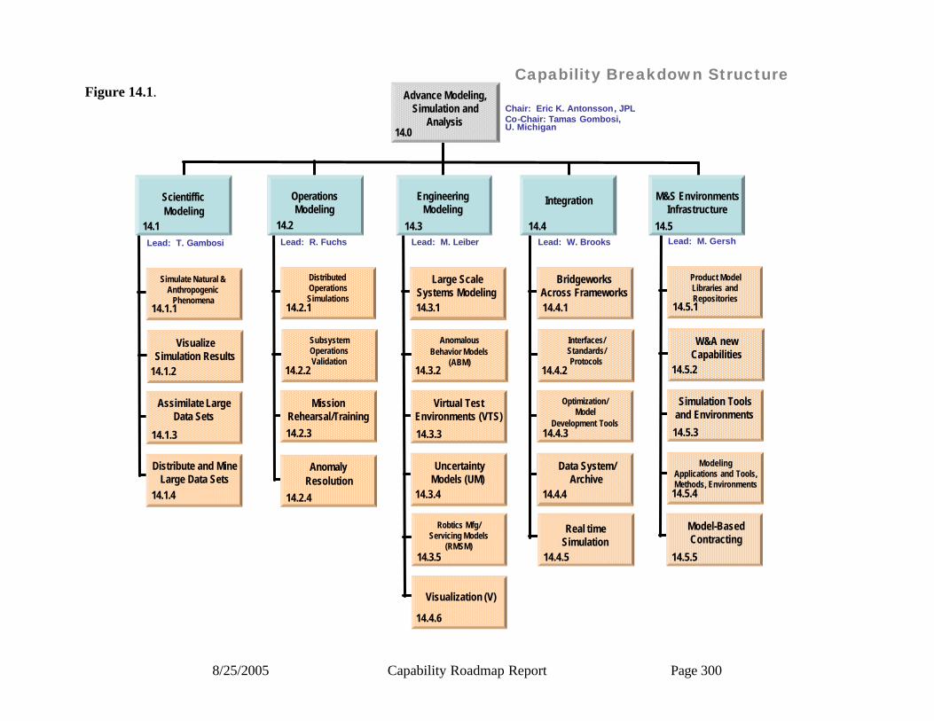
8/25/2005 Capability Roadmap Report Page 300
Capability Breakdown Structure
ScientifficModeling
14.1Lead: T. Gambosi
Simulate Natural &Anthropogenic
Phenomena14.1.1
14.1.2
VisualizeSimulation Results
Assimilate LargeData Sets
14.1.3
14.1.4
Distribute and MineLarge Data Sets
Lead: R. Fuchs
DistributedOperationsSimulations
14.2.1
14.2.2
SubsystemOperationsValidation
MissionRehearsal/Training14.2.3
Lead: M. Leiber
Large ScaleSystems Modeling14.3.1
14.3.2
AnomalousBehavior Models
(ABM)
Virtual TestEnvironments (VTS)
14.3.3
14.3.4
UncertaintyModels (UM)
Lead: W. Brooks
BridgeworksAcross Frameworks14.4.1
14.4.2
Interfaces/Standards/Protocols
Optimization/Model
Development Tools14.4.3
14.4.4
Data System/Archive
Lead: M. Gersh
Product ModelLibraries andRepositories
14.5.1
14.5.2
W&A newCapabilities
Simulation Toolsand Environments
14.5.3
14.5.4
ModelingApplications and Tools,Methods, Environments
14.2 14.3 14.4 14.5
OperationsModeling
EngineeringModeling
Integration M&S EnvironmentsInfrastructure
Real timeSimulation
14.4.5
Model-BasedContracting
14.5.5
Advance Modeling, Simulation and
AnalysisChair: Eric K. Antonsson, JPLCo-Chair: Tamas Gombosi, U. Michigan
AnomalyResolution
14.2.4
Robtics Mfg/Servicing Models
(RMSM)14.3.5
14.4.6
Visualization (V)
14.0
Figure 14.1.

8/25/2005 Capability Roadmap Report Page 301
14.1.10 Roadmap Logic The capability roadmap in this report is a summary level roadmap. This summary level roadmap includes only a roll up of the key sub-capabilities milestone readiness to support a particular mission requirement. Detailed sub-capability and technology roadmaps showing the technology progression and sub-capability development were presented to the NAS and are available in the document sharing system. In the top blue banner of the roadmap, there are those key missions that are pertinent to the roadmap among those derived from the April 15, 2005 interim document delivered by the strategic roadmaps and displayed in the CRM Planning Milestones Chart. The green banner below represents a summary rollup of key capabilities from each of the various capability breakdown structure elements. The peach colored swim-lanes represent the individual top level capability breakdown structure element and the sub-capabilities within this roadmap. The triangles represent the date that the capability is ready to support a given mission, and the diamonds represent decision points The Roadmap is sub-divided by CBS element; Science, Engineering, Operations, Integration, and Infrastructure.
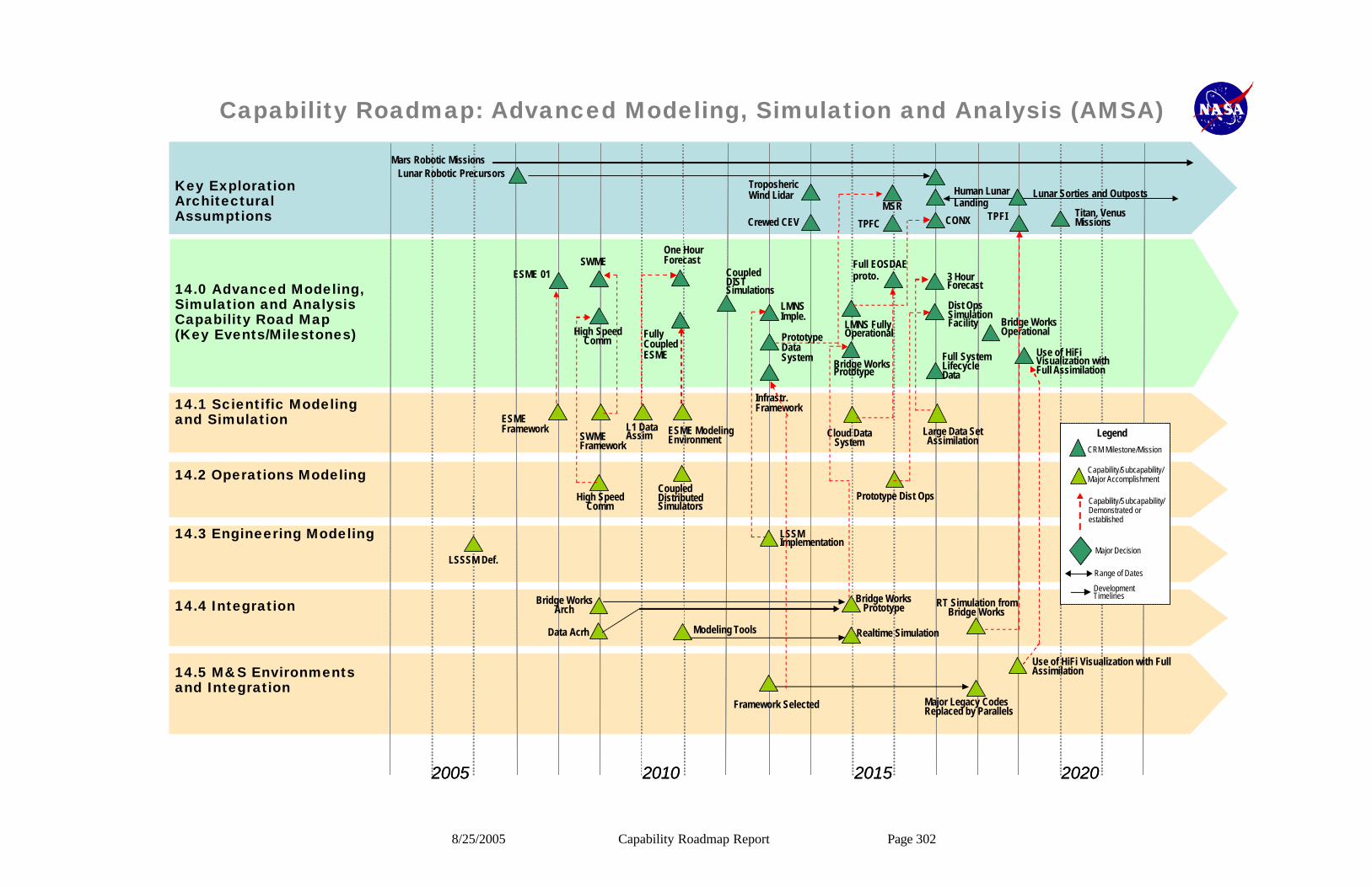
8/25/2005 Capability Roadmap Report Page 302
Capability Roadmap: Advanced Modeling, Simulation and Analysis (AMSA)
14.0 Advanced Modeling, Simulation and Analysis Capability Road Map(Key Events/Milestones)
Key Exploration Architectural Assumptions
2005 2010 202020152005 2010 20202015
14.1 Scientific Modeling and Simulation
14.2 Operations Modeling
14.3 Engineering Modeling
14.4 Integration
14.5 M&S Environments and Integration
Mars Robotic MissionsLunar Robotic Precursors
Crewed CEV
TroposhericWind Lidar
MSR
TPFC
Human Lunar Landing
Lunar Sorties and Outposts
CONXTitan, Venus MissionsTPFI
ESME 01
High Speed Comm
SWMEOne Hour Forecast
Fully Coupled ESME
Coupled DIST Simulations
LMNS Imple.
Prototype Data System
Infrastr. Framework
Full EOSDAE proto. 3 Hour
Forecast
Dist Ops Simulation Facility Bridge Works
Operational
Use of HiFi Visualization with Full Assimilation
Full System Lifecycle Data
ESME Framework
SWME Framework
L1 Data Assim ESME Modeling
Environment
Coupled Distributed Simulators
High Speed Comm
LSSSM Def.
LSSM Implementation
Cloud Data System
Large Data Set Assimilation
Prototype Dist Ops
Bridge Works Arch
Data Acrh Modeling Tools
Framework Selected
Bridge Works Prototype
Realtime Simulation
RT Simulation from Bridge Works
Use of HiFi Visualization with Full Assimilation
Major Legacy Codes Replaced by Parallels
Bridge Works Prototype
LMNS Fully Operational
Capability/Subcapability/Major Accomplishment
Capability/Subcapability/Demonstrated or established
CRM Milestone/Mission
Major Decision
Range of Dates
Development Timelines
Legend
Capability/Subcapability/Major Accomplishment
Capability/Subcapability/Demonstrated or established
CRM Milestone/Mission
Major Decision
Range of Dates
Development Timelines
Legend

8/25/2005 Capability Roadmap Report Page 303
Capability Roadmap: Advanced Modeling, Simulation and Analysis (AMSA)
14.0 Advanced Modeling, Simulation and Analysis Capability Road Map(Key Events/Milestones)
Key Exploration Architectural Assumptions
2020 2025 203520302020 2025 20352030
14.1 Scientific Modeling and Simulation
14.2 Operations Modeling
14.3 Engineering Modeling
14.4 Integration
14.5 M&S Environments and Integration
Mars Robotic Missions
Lunar Sorties and Outposts
In-Space Assembly
Titan, Venus Mission
L1 Diamond
Advanced Titan
Human Mars Mission Life Finder
2031
Mars Atmosphere
Integrated MS&A System
(Fully Ops.) Integrated Dis. Simulation with Human Behavior Models
Dynamic Virtual Environment
24 Hour Forcast
ESME Complete
2nd Gen LMNS
SWME Complete
Sensory Feedback Data Mining1Ebyte@1Tbit/sec
L1 SimulationHigh Resol.Model
Assembly SLE Eval
Anomaly Scenario
Integrate Ops/Behavior Models
Mars Atmosphere Model
2nd Gen LSSM
Agency wide MS&A System Routine Int. MS&A
Realtime Simulation
Full System Lifecycle for all mission critical communities
Systematic use of HiFi VR with assimilation
Venus Samples Return
Routine Integrated MS&A RealtimeSimulations
Visualization Data Mining
Sentinals Data Assimilation
Capability/Subcapability /Major Accomplishment
Capability/Subcapability/Demonstrated or established
CRM Milestone/Mission
Major Decision
Range of Dates
Development Timelines
Legend
Capability/Subcapability /Major Accomplishment
Capability/Subcapability/Demonstrated or established
CRM Milestone/Mission
Major Decision
Range of Dates
Development Timelines
Legend
8/25/2005 Capability Roadmap Report Page 304
14.1.11 Relationship to Other Roadmaps All of the other roadmaps can benefit from the fundamental capabilities derived from ASMA. As ASMA capabilities mature, and are improved and integrated, many will become “enabling” for other Capability Roadmaps. A general conclusion across all capability areas is that ASMA is not identified with any one mission directorate or any unique set of missions. It should be considered an area for strategic investment by NASA, focused on critical needs, but recognized as having broad applications and benefits. 14.2 Summary It is important to note that a significant use of AMSA not explicitly addressed in this report is modeling for Business Decision Support. AMSA capabilities can help facilitate information exchange to NASA's diverse set of constituents (i.e. Congress, the Executive Branch, NASA advisory committees, and the public). Furthermore, the quality of Agency tactical decisions can also be significantly enhanced by more widespread use of AMSA. In the science domain, AMSA is already used as the basis for decisions that can have serious consequences for the public, such as the use of high-fidelity simulations to predict weather. The corresponding role of ASMA in the engineering and operations domains will be to provide credible, model-based assessments of architectures, missions, systems, concepts, and technologies to support NASA investment decisions.
However, the system envisioned in this roadmap is not a simple system. It will require resources to develop and maintain it, but just as importantly, coordination with other agencies and affiliated industries to develop a rigorous methodology for the systematic, aggressive use of these capabilities. Processes must be developed and refined to ensure that the benefits out lined do in fact occur. Understanding the limits and uncertainties of state-of-the-art ASMA is part of this process, and needs to be continually improved. In addition, NASA internal training must become much more focused on the use of such tools and the methodology for systematically using simulations and modeling as part of standard practice throughout the agency.

8/25/2005 Capability Roadmap Report Page 305
Acronym list AFL Astrobiology Field Laboratory AI Artificial Intelligence CEV Crew Exploration Vehicle CMBPoL Cosmic Microwave Background Polarization EDL Entry Descent, Landing ESSP Earth System Science Program FIR Far Infrared GEC Geospace Electrodynamic Connections HWIL Hardware in the loop InSAR Interferometric Synthetic Aperture Radar JIMO Jupiter Icy Moon Obiter JWST WFS&C James Webb Space Telescope Wavefront Sensing & Control JWST/MIRI James Webb Space Telescope Mid-Infrared Instrument LISA Laser Interferometer Space Antenna L1 Earth libration point orbit MAXIM Micro Arcsecond X-Ray Imaging Mission MER Mars Exploration Rover MHD Magnetohydrodynamic MS&A Modeling, Simulation and Analysis MSL Mars Science Laboratory NPP NPOESS Preparatory Project NPOESS National Polar-Orbiting Operational Environment Satellite System PFF Precision Formation Flying SAFIR Single Aperture Far-Infrared Telescope SAR Synthetic Aperture Radar SDO Space Dynamics Observatory SEC Mag Sun Earth Connection Magnetometry Misions SI Stellar Imager SIM Space Interferometry Mission SPECS Sub-millimeter Probe of the Evolution of Cosmic Structures SR Sample Return TPF-C Terrestrial Planet Finder-Coronagraph TPF-I Terrestrial Planet Finder-Interferometer TPS Thermal Protection System TRL Technology Readiness Level VV&A Verification, Validation, and Accreditation VISE Venus In-situ Exploration VR Virtual Reality WISE Wide Field Infrared Survey Explorer

8/25/2005 Capability Roadmap Report Page 306
Appendix A: Papers and Analyses Referenced by the ASMA Team
• Accelerating Technology Transition Bridging the Valley of Death for Materials and processes in Defense Systems; NRC ISBN 0-309-09317-1 Board on Manufacturing and Engineering Design 500 Fifth Street, N.W. Washington, DC 20001 [email protected] http://www.nas.edu/bmed
• Aeronautics Capacity Models - Robert E Yackovetsky, Aeronautics Systems Analysis Branch, NASA - Langley Research Center, January 10, 2005
• Aeronautics Research Mission Directorate (ARMD) Modeling, Simulation and Analysis Perspectives, Needs, and Priorities White Paper - Wendell Ricks, NASA - Langley Research Center, March 2005
• Risk-based Prioritization of Research for Aviation Security Using Logic-Evolved Decision Analysis - Aeronautics Systems Analysis Branch, NASA - Langley Research Center, January 12, 2005
• Code Y/R High-End computing (HEC) Partnership Plan, Initiated by Code Y and Code R, Tsengdar Lee, Jerome Bennett, Eugene Tu, August 21 & 22, 2004
• Cyberinfrastructure for the Atmospheric Sciences in the 21st Century, A report from the Ad Hoc Committee for Cyberinfrastructure, Research, Development and Education in the Atmospheric Sciences, June 2004
• Exploration Systems Mission Directorate, Spiral I Acquisition Strategy, Mike Heckler, 16 November 2004
• Federal Plan for High-End Computing, Report of the High-End Computing Revitalization Task Force (HECRTF) May 10, 2004 (Second Printing - July 2004)
• Getting Up to Speed - The Future of Supercomputing, Susan L. Graham, Marc Snir, and Cynthia A. Patterson, Editors. Committee on the Future of Supercomputing, Computer Science and Telecommunications Board Division of Engineering and Physical Sciences NRC, Prepublication Copy, National Academies Press http://www.nap.edu
• Information Science Update - NASA Advisory Council Meeting, December 4, 2003 - Daniel Clancy
• Living on a Restless Planet - Solid Earth Science Working Group, November 5, 2002 • NASA Report from the Earth Science Enterprise Computational Technology
Requirements Workshop, April 30, 2002 • Preparing for the Human Exploration of Mars: Developing the Measurement Database
to Ensure the Safety of Humans Exploring & Living on Mars — RASC Study Briefing to ESMD, Joel S. Levine and Marianne Rudisill, April 2005.
• Review of NASA’s Aerospace Technology Enterprise, An Assessment of NASA’s Pioneering Revolutionary Technology Program. Committee for the Review of NASA’s Pioneering Revolutionary Technology (PRT) Program, Aeronautics and Space Engineering Board, Division on Engineering and Physical Sciences - NRC ISBN 0-309-09080-6 http://www.nas.edu
• Safe on Mars, Precursor Measurements Necessary to Support Human Operations on the Martian Surface. Committee on Precursor Measurements Necessary to Support Human

8/25/2005 Capability Roadmap Report Page 307
Operations on the Surface of Mars, Aeronautics and Space Engineering Board, Space Studies Board, Division on Engineering and Physical Sciences NRC. http://www.nas.edu
• Science Modeling and Analysis on Project Columbia, prepared for ESSAAC, Tsengdar Lee, Joseph Bredekamp, Jack Kaye, Martha Maiden, Francis Lindsay, Michael Goodman, Jim Fischer, Barbara Pfarr, Science Mission Directorate - NASA Advanced Simulator Division, NASA Goddard IT Pathfinder Working Group, September 10, 2004
• Science Mission Directorate Sun-Earth System Models & Analysis Systems, Working Draft, Version 2.2, October 2004
• Advanced Engineering Environments: Achieving the Vision: Phase 1 (1999), http://books.nap.edu/catalog/9597.html
• Design in the New Millennium: Advanced Engineering Environments: Phase 2 (2000), http://books.nap.edu/catalog/9876.html
• Modeling and Simulation in Manufacturing and Defense Acquisition: Pathways to Success (2002), Board on Manufacturing and Engineering Design (BMED) http://books.nap.edu/openbook/0309084822/html/index.html
• Technology for the US Navy & Marine Corps, vol. 9: Modeling & Simulation http://www.nap.edu/html/tech_21st/msindex.htm#Contents
Appendix B: Presentations to ASMA Team Presentation Title Presenter Organization November 30, 2004: Virtual Immersion into Data William Campbell NASA – GSFC Distributed Space Systems George Davis Emergent Space Tech. Goals and Challenges Mark Gersh Lockheed Martin Mission Design Cindy Kurt United Space Alliance Automated Design Systems Jason Lohn NASA – ARC Experimentally Validated Simulation Doun Van Gilder AFRL, VPI, UCLA, JPL SRNL Capabilities Michael Williams Savannah River Nat’l Lab New Trajectories Martin Lo NASA JPL UGS/Team Center Capabilities Aaron Johns UGS Coupled Science Models Dave Smith Boeing Parallel Meshing Charles Norton NASA – JPL/GSFC Health Management Systems Sanjay Garg NASA – GSFC Technology Infusion Assessment System Trygve Magelssen Futron Corporation January 6, 2005: NASA Planetary Exploration Needs Jim Cutts NASA – JPL Jim Robinson NASA – HQ NASA Supercomputing Walt Brooks NASA –ARC Ocean Modeling and Data Assimilation Ichiro Fukumori NASA – JPL Solid Earth Modeling Andrea Donnellan NASA – JPL Advanced Visualization Erik DeJong NASA – JPL

8/25/2005 Capability Roadmap Report Page 308
Integrated Optical Systems Marie Levine-West NASA – JPL Earth System Modeling Framework Cecelia DeLuca NCAR Space Weather Modeling Framework Quentin Stout Univ. of Michigan Industrial Modeling Ron Fuchs Boeing FEM Michael Ortiz CIT Sandia Modeling and Simulation Carl Peterson Sandia Engineering Modeling at NGST Karen Fucik NGST Engineering and Modeling Data Center Ricky Rood NASA – GSFC Nano-technology Paul von Allmen NASA – JPL February 10, 2005: NASA Universe Needs Jim Breckinridge NASA – JPL Web-centric Modeling and Simulation J. Mark Pullen George Mason Univ. Planetary Atmospheres Robert Tolson Univ. of NC Observing System Sim. Experiments Bob Atlas NASA – GSFC NASA Sun-Earth Needs Don Anderson NASA – HQ Future Computing Architectures Larry Smarr UC – San Diego Climate Modeling Jim Kinter COLA Stellar Atmospheres Thierry Lanz NASA – GSFC Data Driven Application Systems Frank Lindsey NASA – HQ Dynamic Data Driven App. Systems Frederica Darema NSF – CISE Galaxy Interactions Romeel Davé Univ. of AZ
8/25/2005 Capability Roadmap Report Page 309
NASA
Systems Engineering Cost/Risk Analysis Roadmap
Take-Away*
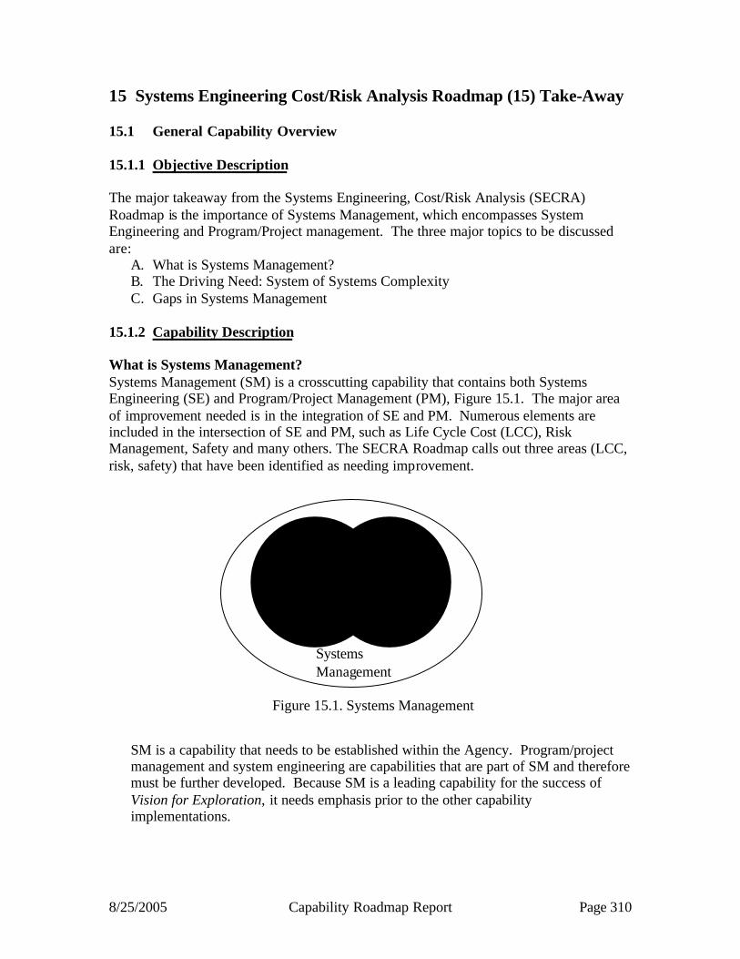
8/25/2005 Capability Roadmap Report Page 310
15 Systems Engineering Cost/Risk Analysis Roadmap (15) Take-Away 15.1 General Capability Overview 15.1.1 Objective Description The major takeaway from the Systems Engineering, Cost/Risk Analysis (SECRA) Roadmap is the importance of Systems Management, which encompasses System Engineering and Program/Project management. The three major topics to be discussed are:
A. What is Systems Management? B. The Driving Need: System of Systems Complexity C. Gaps in Systems Management
15.1.2 Capability Description What is Systems Management? Systems Management (SM) is a crosscutting capability that contains both Systems Engineering (SE) and Program/Project Management (PM), Figure 15.1. The major area of improvement needed is in the integration of SE and PM. Numerous elements are included in the intersection of SE and PM, such as Life Cycle Cost (LCC), Risk Management, Safety and many others. The SECRA Roadmap calls out three areas (LCC, risk, safety) that have been identified as needing improvement.
SM is a capability that needs to be established within the Agency. Program/project management and system engineering are capabilities that are part of SM and therefore must be further developed. Because SM is a leading capability for the success of Vision for Exploration, it needs emphasis prior to the other capability implementations.
Systems Management
Systems Engineering
Program/ Project Management
Figure 15.1. Systems Management
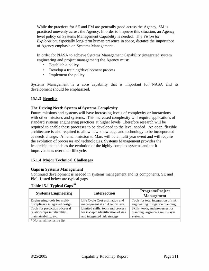
8/25/2005 Capability Roadmap Report Page 311
While the practices for SE and PM are generally good across the Agency, SM is practiced unevenly across the Agency. In order to improve this situation, an Agency level policy on Systems Management Capability is needed. The Vision for Exploration, especially long-term human presence in space, dictates the importance of Agency emphasis on Systems Management. In order for NASA to achieve Systems Management Capability (integrated system engineering and project management) the Agency must:
• Establish a policy • Develop a training/development process • Implement the policy
Systems Management is a core capability that is important for NASA and its development should be emphasized. 15.1.3 Benefits The Driving Need: System of Systems Complexity Future missions and systems will have increasing levels of complexity or interactions with other missions and systems. This increased complexity will require applications of standard systems engineering practices at higher levels. Therefore research will be required to enable these processes to be developed to the level needed. An open, flexible architecture is also required to allow new knowledge and technology to be incorporated as needs change. A human mission to Mars will be a multi-year event and will require the evolution of processes and technologies. Systems Management provides the leadership that enables the evolution of the highly complex systems and the ir improvements over their lifecycle. 15.1.4 Major Technical Challenges Gaps in Systems Management Continued development is needed in systems management and its components, SE and PM. Listed below are typical gaps.
Table 15.1 Typical Gaps* Systems Engineering Intersection Program/Project
Management Engineering tools for multi-disciplinary integrated design
Life Cycle Cost estimation and management at an Agency level
Tools for total integration of risk, engineering mitigation planning
Tools for prediction of causal relationships in reliability, maintainability, etc.
Limited skills, tools and process for in-depth identification of risk and integrated risk strategy
Skills, tools, and processes for planning large-scale multi-layer systems.
* Not an all inclusive list

8/25/2005 Capability Roadmap Report Page 312
Capability Breakdown Structure
Systems Engineering
15.1Lead: Dr. Alan Wilhite/GT
Engineering
15.1.1
15.1.2
Support
Lead: Dr. Dave Bearden /Aerospace
Tools
15.2.1
15.2.2Skills
Process
15.2.3
Lead: Ted Hammer/HQ
Prepare for RiskManagement
15.3.1
15.3.2
Identify &Analyze Risks
Lead:Dr. Homayoon Dezfuli/HQ
SystemSafety
15.4.1
15.4.2
System Reliability
15.2 15.3 15.4
Life CycleCosting
RiskManagement
Safety & ReliabilityAnalysis
SE, Cost & RiskAnalysis
NASA Chair: Steve Cavanaugh (LaRC)External Chair: Dr. Alan Wilhite (Georgia Tech)
15.0
ProcessManagement
15.1.1
15.1.2
ProjectManagement
15.3.2
Mitigate Risks
15.4.2
SafetyManagement
Figure 15.2

8/25/2005 Capability Roadmap Report Page 313
Acronyms LCC Life Cycle Cost PM Program/Project Management SE Systems Engineering SECRA Systems Engineering, Cost/Risk Analysis

8/25/2005 Capability Roadmap Report Page 314
NASA
Capability Road Map (CRM) 16
Nanotechnology Capability Roadmap
Executive Summary
Co-Chair: Minoo Dastoor, NASA Co-Chair: Murray Hirschbein, NASA
External Co-Chair: Dimitris Lagoudas, Texas A&M Univ
Coordinators
Directorate
Harley Thronson, NASA SMD Giulio Varsi, NASA SMD
APIO
Julie Crooke, NASA GSFC
Team Members
NASA / JPL / DOE
Mike Meador, NASA GRC
Harry Partridge, NASA ARC Mia Siochi, NASA LaRC Mike Smith, NASA LaRC
Benny Toomarian, NASA JPL Len Yowell, NASA JSC
Academia
Wade Adams, Rice University Ilhan Aksav, Princeton University Supriyo Datta, Purdue University David Janes, Purdue University
Chih-Ming Ho, UCLA
Industry
Dan Herr, SRC John Starkovich, Northrop-Grumman
Stan Williams, Hewlett-Packard
8/25/2005 Capability Roadmap Report Page 315
16 Nanotechnology Capability Roadmap (Roadmap 16) 16.1 General Capability Overview 16.1.1 Capability Description The purpose of this roadmap is to develop a pathway for NASA to exploit the benefits of nanotechnology to achieve long-term goals in human space exploration, space science, and aeronautics research. As the result of advances in our ability to observe and manipulate matter and compute ever more complex and demanding problems, we have reached the point where we can design and engineer materials and devices at the nanometer scale. At this scale (1 nm to 100 nm) we can approach the theoretical limits of material properties and, in addition, entirely unique properties emerge that do not occur naturally at larger scales. This roadmap encompasses controlling the mechanical, optical, electrical and thermal properties of matter at the nano-scale and the subsequent design and the development of sensors, devices and systems from the nano-scale through the macro-scale for specific NASA needs. Principally, it emphasizes the underlying technology and applications that will serve as the foundation for higher- level mission specific applications across the other capability areas. The roadmap focuses on specific technical areas of high priority to NASA. Principal areas emphasized are: 1) ultra-high performance and multifunctional nano-structured materials, 2) ultra-small and sensitive nanosensors and devices, 3) high-density, low power nanoelectronics, and 4) integrated intelligent systems. 16.1.2 Benefits 16.1.2.1 Nanomaterials: Design of materials at the molecular level is expected to provide for strength approaching theoretical limits (i.e. 10% of their elastic modulus). Carbon nanotubes can be very close to their theoretical strength that is about 100X that of steel at 1/6 the weight. Nano-scale materials can be produced with electrical conductivity 1000X higher than copper; better thermal conductivity than diamond or insulating properties equal to the best aerogels. Control of the morphology and composition at the nano-scale can increase the damping or decrease thermal expansion by an order of magnitude. Ultimately, completely new design concepts can be enabled by multifunctional materials tailored by combining a specific set of properties for a specific application. Over the next decade, materials are expected to become available with 5X the specific strength (i.e. strength-to-weight ratio). By 2020 nano-scale materials could result in up to a 1/3 weight savings in spacecraft and aircraft structures, as well as thermal protection systems for atmospheric entry, and a 2/3 weight reduction by ~2035. Photovoltaic arrays based on nanostructures (e.g. quantum dots or quantum rods) are predicted to achieve about 50% efficiency by around 2020, well above the limits of current crystalline solar arrays.

8/25/2005 Capability Roadmap Report Page 316
Figure 16.1: Expected vehicle dry weight reduction using nano-structured materials (Left) Predicted potential dry weight reduction by replacing Al or CFC with CNC, with no design modification to best utilize the properties of the new material. Based on a reference design for a reusable launch vehicle and theoretical material propeties.
16.1.2.2 Nanosensors : Nano-scale sensors are highly tailorable and can achieve single-photon sensitivity and single-molecule detection. They can be made from a wide variety of nano-structures including quantum dots, nano-rods, chemically functionalized nanotubes and specially engineered segments of DNA and other biological molecules. They are also readily integrated with sensor electronics to produce very compact, highly “intelligent” instruments. The rate of progress in this area is very rapid: NASA will fly a sensor with a very compact, low-power nanotube-based electron source on the Mars Science Lander. By 2010, we should be able to produce an entire sensor system on a chip. 16.1.2.3 Nanoelectronics: By 2020, the most advanced micro-electronics will have feature sizes – by industry projections – below 20 nanometers. A key overall goal is to improve the performance of processors and memory by a factor of 1000 with no increase in power consumption. It is also expected that on a general scale of “trillions per chips” (e.g. bytes, trans istors), the systems will be highly fault tolerant. An additional feature of nano-scale electronics is that in many cases they tend to be highly radiation resistant (due to their small target cross-section) – or can be made radiation tolerant without special processing/fabrication methods. By about 2015, radiation-hard, fault-tolerant electronics for ultra- low noise electronics should be available. 16.1.2.4 Intelligent Systems: When the above nanoscale phenomena are integrated, their combined effects can be greater than the individual benefits. Integrating sensors, electronics, power and materials can produce multi-functional systems that can be very responsive to their environment, both in an active self-protective manner and to acquire scientific data. For example, on the protective side, materials can be self-healing if damaged and modulate thermal emissivity to control internal temperature. On the data acquisition side, sensors systems can adapt – or evolve – to be most responsive to the
VehicleDryWeight
1.0
AluminumCarbon
FiberComposite
CarbonNanotubeComposite
55 % reduction
82% Reduction
Predicted Weight Savings from Nano-Structured Materials(Primary Structure and Cryogenic Fuel Tanks)

8/25/2005 Capability Roadmap Report Page 317
data they “experience.” At the systems level, integrated multi- functional nanotechnology offers new approaches for diverse application such as life support, human health monitoring and vehicle health monitoring. At the level of an entire spacecraft, over the next decade we should be able to build a 1 kg spacecraft with the full capability of a 100 kg spacecraft today – and achieve an additional 10X reduction by about 2020. 16.1.3 Specific Example of Capability Benefits for Exploration Systems: In the next 5-10 years: Cryogen propellant tanks comprise a large fraction (>50%) of the dry mass of any exploration vehicle. Nanostructured materials will provide a means for reducing the mass of these tanks by 20-30% over conventional composite cryotanks. Polymer/clay nanocomposites with hydrogen permeabilities more than 100 times less than that of conventional epoxy composites will be developed for use as the inner wall of the cryotank. This will eliminate the need for a metal liner, typically used on the inner wall, thereby reducing cryotank weight and improving durability. Furthermore, polymer cross- linked aerogels, currently under development within NASA, can be used as ultra- lightweight insulation, replacing less durable polyurethane foams. In the next 10-15 years: EVA suit designers want to reduce the mass of the suit and the PLSS (Personal Life Support System) by over 50%. Packaging (the hard exterior) accounts for a large portion of the mass of the PLSS. Use of durable cross-linked aerogels could reduce the mass of the PLSS case by more than 30% over a conventional composite design. These aerogels could serve “double duty” as both PLSS structure and, when doped with suitable catalysts, as an air purification system that scrubs carbon dioxide from the astronaut’s breathing air. Multi- layer insulation (MLI) that is currently used on the EVA suits for Shuttle will not function in a Martian environment. Flexible aerogel compositions have been developed that could be used as MLI replacements, reducing the bulkiness of the suit and improving astronaut mobility and dexterity.
16.1.4 Key Architecture / Strategic Decisions Among the fifteen Capability Roadmaps, nanotechnology is the only one that is purely technology. It represents an underlying capability for the other fourteen capability areas, which are the principle “customers” for nanotechnology. As such, key architectural/strategic decisions will determine the specific priority investment areas for nano-scale technology. Table 16.1 - Key Nanotechnology Architecture/Strategic Decisions
Key Architecture/ Strategic Decisions
Date Decision is Needed
Impact of Decision on Capability
NASA LONG-TERM GOALS REQUIRE A SUSTAINED, SYSTEMATIC INVESTMENT IN LEADING-EDGE TECHNOLOGY TO ACHIEVE NECESSARY LEVELS OF PERFORMANCE, SAFETY, COST , AND RELIABILITY.
2006
MAJOR MASS REDUCTION IN SPACE AND AERONAUTICAL SYSTEMS; SUPERIOR RADIATION SHIELDING; EFFICIENT LIFE SUPPORT PROCESSES (E.G. WATER PURIFICATION, AIR FILTRATION); HIGHLY MINIATURIZED AND SENSITIVE INSTRUMENTS FOR SCIENCE , ASTRONAUT MONITORING, AND IVHM; HIGHER LEVELS OF AUTONOMY; GREATER ENERGY EFFICIENCY (ELECTRONICS AND POWER SYSTEMS).
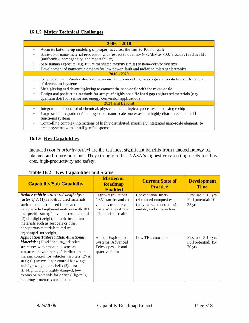
8/25/2005 Capability Roadmap Report Page 318
16.1.5 Major Technical Challenges
2006 – 2010 • Accurate bottoms -up modeling of properties across the 1nm to 100 nm scale • Scale-up of nano-material production with respect to quantity (~kg/day to ~100’s kg/day) and quality
(uniformity, homogeneity, and repeatability) • Safe human exposure (e.g. future mandated toxicity limits) to nano-derived systems • Development of nano-scale devices for low power, fault and radiation tolerant electronics
2010 - 2020 • Coupled quantum/molecular/continuum mechanics modeling for design and prediction of the behavior
of devices and systems • Multiplexing and de-multiplexing to connect the nano-scale with the micro-scale • Design and production methods for arrays of highly specific band-gap engineered materials (e.g.
quantum dots) for sensor and energy conversion applications 2020 and Beyond
• Integration and control of chemical, physical, and biological processes onto a single chip • Large-scale integration of heterogeneous nano-scale processes into highly distributed and multi-
functional systems • Controlling complex interactions of highly distributed, massively integrated nano-scale elements to
create systems with “intelligent” response 16.1.6 Key Capabilities Included (not in priority order) are the ten most significant benefits from nanotechnology for planned and future missions. They strongly reflect NASA’s highest cross-cutting needs for: low-cost, high-productivity and safety. Table 16.2 – Key Capabilities and Status
Capability/Sub-Capability Mission or Roadmap Enabled
Current State of Practice
Development Time
Reduce vehicle structural weight by a factor of 3: (1) nanostructured materials such as nanotube based fibers and nanoparticle toughened matrixes with 10X the specific strength over current materials; (2) ultralightweight, durable insulation materials such as aerogels or other nanoporous materials to reduce cryopropellant weight.
Lightweight launch, CEV transfer and air vehicles (remotely operated aircraft and all electric aircraft)
Conventional fiber-reinforced composites (polymers and ceramics), metals, and super-alloys
First use: 5-10 yrs Full potential: 20-25 yrs
Application Tailored Multi-functional Materials: (1) self-healing, adaptive structures with embedded sensors, actuators, power storage/distribution and thermal control for vehicles, habitats, EVA suits; (2) active shape control for wings and lightweight aeroshells (3) ultra-stiff/lightweight, highly damped, low expansion materials for optics (~kg/m2), metering structures and antennas.
Human Exploration Systems, Advanced Telescopes, air and space vehicles
Low TRL concepts First use: 5-10 yrs Full potential: 15-20 yrs
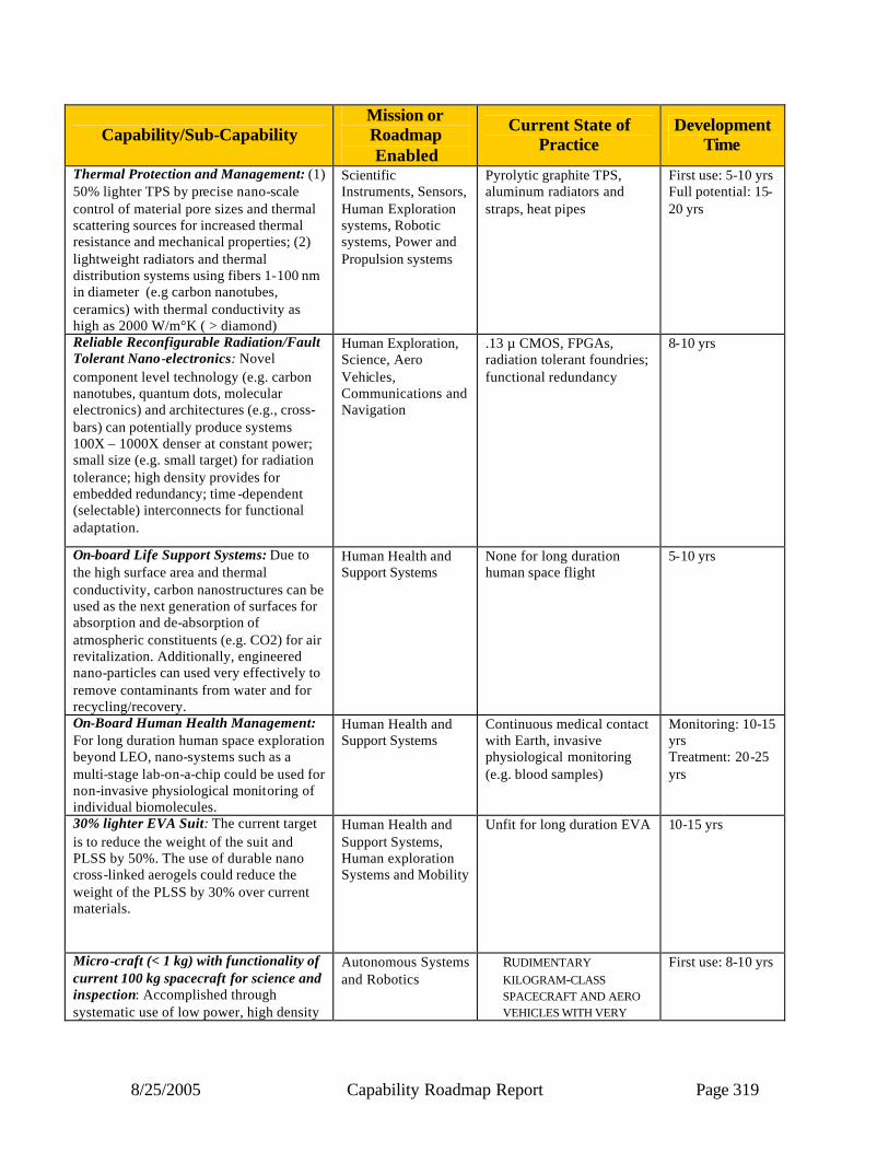
8/25/2005 Capability Roadmap Report Page 319
Capability/Sub-Capability Mission or Roadmap Enabled
Current State of Practice
Development Time
Thermal Protection and Management: (1) 50% lighter TPS by precise nano-scale control of material pore sizes and thermal scattering sources for increased thermal resistance and mechanical properties; (2) lightweight radiators and thermal distribution systems using fibers 1-100 nm in diameter (e.g carbon nanotubes, ceramics) with thermal conductivity as high as 2000 W/m°K ( > diamond)
Scientific Instruments, Sensors, Human Exploration systems, Robotic systems, Power and Propulsion systems
Pyrolytic graphite TPS, aluminum radiators and straps, heat pipes
First use: 5-10 yrs Full potential: 15-20 yrs
Reliable Reconfigurable Radiation/Fault Tolerant Nano-electronics: Novel component level technology (e.g. carbon nanotubes, quantum dots, molecular electronics) and architectures (e.g., cross-bars) can potentially produce systems 100X – 1000X denser at constant power; small size (e.g. small target) for radiation tolerance; high density provides for embedded redundancy; time -dependent (selectable) interconnects for functional adaptation.
Human Exploration, Science, Aero Vehicles, Communications and Navigation
.13 µ CMOS, FPGAs, radiation tolerant foundries; functional redundancy
8-10 yrs
On-board Life Support Systems: Due to the high surface area and thermal conductivity, carbon nanostructures can be used as the next generation of surfaces for absorption and de-absorption of atmospheric constituents (e.g. CO2) for air revitalization. Additionally, engineered nano-particles can used very effectively to remove contaminants from water and for recycling/recovery.
Human Health and Support Systems
None for long duration human space flight
5-10 yrs
On-Board Human Health Management: For long duration human space exploration beyond LEO, nano-systems such as a multi-stage lab-on-a-chip could be used for non-invasive physiological monitoring of individual biomolecules.
Human Health and Support Systems
Continuous medical contact with Earth, invasive physiological monitoring (e.g. blood samples)
Monitoring: 10-15 yrs Treatment: 20-25 yrs
30% lighter EVA Suit: The current target is to reduce the weight of the suit and PLSS by 50%. The use of durable nano cross-linked aerogels could reduce the weight of the PLSS by 30% over current materials.
Human Health and Support Systems, Human exploration Systems and Mobility
Unfit for long duration EVA 10-15 yrs
Micro-craft (< 1 kg) with functionality of current 100 kg spacecraft for science and inspection: Accomplished through systematic use of low power, high density
Autonomous Systems and Robotics
RUDIMENTARY KILOGRAM-CLASS SPACECRAFT AND AERO VEHICLES WITH VERY
First use: 8-10 yrs
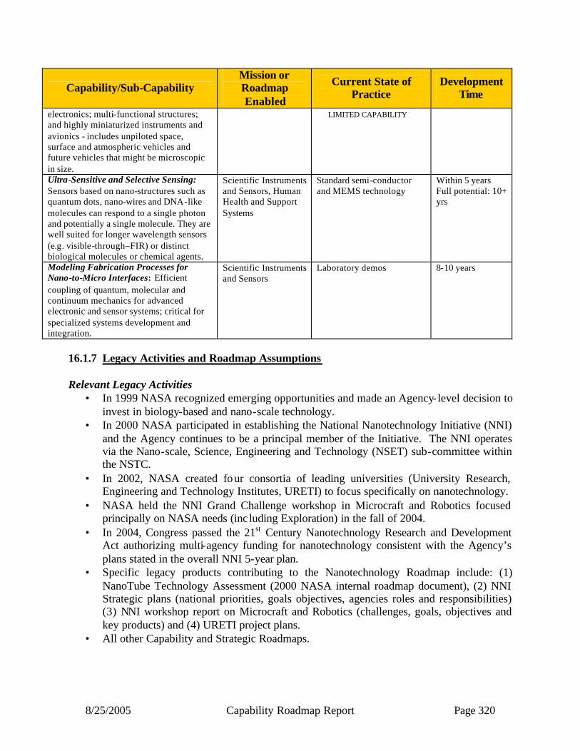
8/25/2005 Capability Roadmap Report Page 320
Capability/Sub-Capability Mission or Roadmap Enabled
Current State of Practice
Development Time
electronics; multi-functional structures; and highly miniaturized instruments and avionics - includes unpiloted space, surface and atmospheric vehicles and future vehicles that might be microscopic in size.
LIMITED CAPABILITY
Ultra-Sensitive and Selective Sensing: Sensors based on nano-structures such as quantum dots, nano-wires and DNA-like molecules can respond to a single photon and potentially a single molecule. They are well suited for longer wavelength sensors (e.g. visible-through–FIR) or distinct biological molecules or chemical agents.
Scientific Instruments and Sensors, Human Health and Support Systems
Standard semi-conductor and MEMS technology
Within 5 years Full potential: 10+ yrs
Modeling Fabrication Processes for Nano-to-Micro Interfaces: Efficient coupling of quantum, molecular and continuum mechanics for advanced electronic and sensor systems; critical for specialized systems development and integration.
Scientific Instruments and Sensors
Laboratory demos 8-10 years
16.1.7 Legacy Activities and Roadmap Assumptions Relevant Legacy Activities
• In 1999 NASA recognized emerging opportunities and made an Agency- level decision to invest in biology-based and nano-scale technology.
• In 2000 NASA participated in establishing the National Nanotechnology Initiative (NNI) and the Agency continues to be a principal member of the Initiative. The NNI operates via the Nano-scale, Science, Engineering and Technology (NSET) sub-committee within the NSTC.
• In 2002, NASA created four consortia of leading universities (University Research, Engineering and Technology Institutes, URETI) to focus specifically on nanotechnology.
• NASA held the NNI Grand Challenge workshop in Microcraft and Robotics focused principally on NASA needs (inc luding Exploration) in the fall of 2004.
• In 2004, Congress passed the 21st Century Nanotechnology Research and Development Act authorizing multi-agency funding for nanotechnology consistent with the Agency’s plans stated in the overall NNI 5-year plan.
• Specific legacy products contributing to the Nanotechnology Roadmap include: (1) NanoTube Technology Assessment (2000 NASA internal roadmap document), (2) NNI Strategic plans (national priorities, goals objectives, agencies roles and responsibilities) (3) NNI workshop report on Microcraft and Robotics (challenges, goals, objectives and key products) and (4) URETI project plans.
• All other Capability and Strategic Roadmaps.
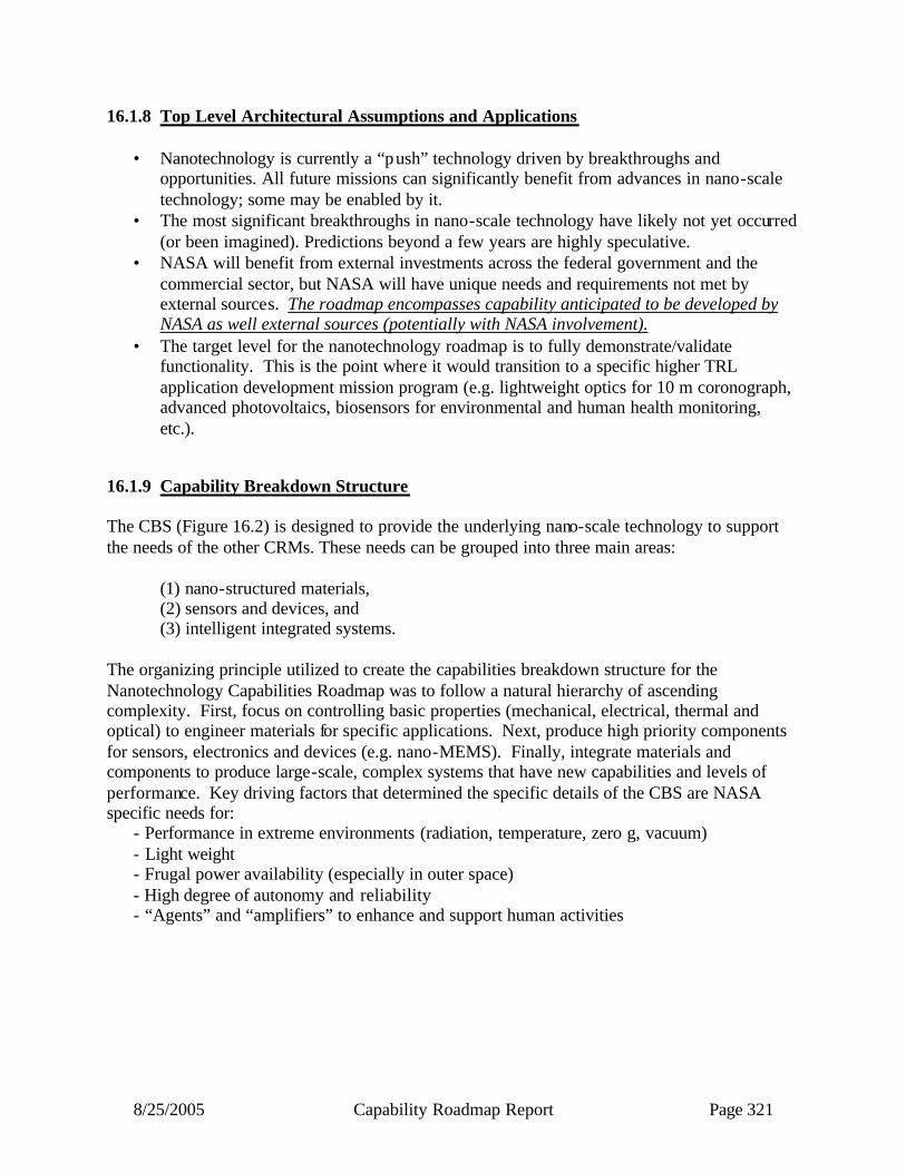
8/25/2005 Capability Roadmap Report Page 321
16.1.8 Top Level Architectural Assumptions and Applications • Nanotechnology is currently a “push” technology driven by breakthroughs and
opportunities. All future missions can significantly benefit from advances in nano-scale technology; some may be enabled by it.
• The most significant breakthroughs in nano-scale technology have likely not yet occurred (or been imagined). Predictions beyond a few years are highly speculative.
• NASA will benefit from external investments across the federal government and the commercial sector, but NASA will have unique needs and requirements not met by external sources. The roadmap encompasses capability anticipated to be developed by NASA as well external sources (potentially with NASA involvement).
• The target level for the nanotechnology roadmap is to fully demonstrate/validate functionality. This is the point where it would transition to a specific higher TRL application development mission program (e.g. lightweight optics for 10 m coronograph, advanced photovoltaics, biosensors for environmental and human health monitoring, etc.).
16.1.9 Capability Breakdown Structure The CBS (Figure 16.2) is designed to provide the underlying nano-scale technology to support the needs of the other CRMs. These needs can be grouped into three main areas:
(1) nano-structured materials, (2) sensors and devices, and (3) intelligent integrated systems.
The organizing principle utilized to create the capabilities breakdown structure for the Nanotechnology Capabilities Roadmap was to follow a natural hierarchy of ascending complexity. First, focus on controlling basic properties (mechanical, electrical, thermal and optical) to engineer materials for specific applications. Next, produce high priority components for sensors, electronics and devices (e.g. nano-MEMS). Finally, integrate materials and components to produce large-scale, complex systems that have new capabilities and levels of performance. Key driving factors that determined the specific details of the CBS are NASA specific needs for: - Performance in extreme environments (radiation, temperature, zero g, vacuum) - Light weight - Frugal power availability (especially in outer space) - High degree of autonomy and reliability - “Agents” and “amplifiers” to enhance and support human activities
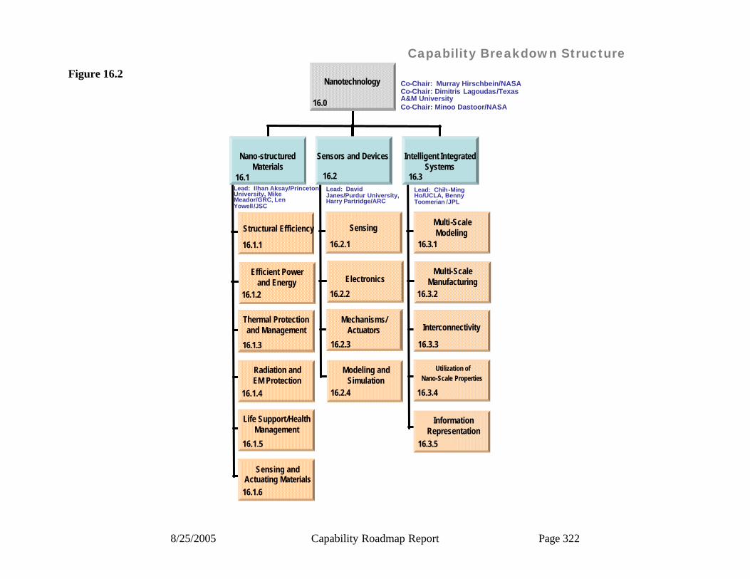
8/25/2005 Capability Roadmap Report Page 322
Capability Breakdown Structure
Nano-structuredMaterials
16.1Lead: Ilhan Aksay/Princeton University, Mike Meador/GRC, Len Yowell /JSC
Structural Efficiency
16.1.1
16.1.2
Efficient Powerand Energy
Thermal Protectionand Management
16.1.3
16.1.4
Radiation andEM Protection
Lead: David Janes/Purdur University, Harry Partridge/ARC
Sensing
16.2.1
16.2.2
Electronics
Mechanisms/Actuators
16.2.3
Lead: Chih-Ming Ho/UCLA, Benny Toomerian /JPL
Multi-ScaleModeling
16.3.1
16.3.2
Multi-ScaleManufacturing
Interconnectivity
16.3.3
16.3.4
Utilization ofNano-Scale Properties
16.2 16.3
Sensors and Devices Intelligent IntegratedSystems
Nanotechnology Co-Chair: Murray Hirschbein/NASACo-Chair: Dimitris Lagoudas/Texas A&M UniversityCo-Chair: Minoo Dastoor/NASA
Life Support/HealthManagement
16.1.5
16.1.6
Sensing andActuating Materials
16.2.4
Modeling andSimulation
16.3.5
InformationRepresentation
16.0
Figure 16.2

8/25/2005 Capability Roadmap Report Page 323
16.1.10 Roadmap Logic The roadmaps are divided into three groups:
• Exploration (Fig. 16.3a and 16..3b) • Science (Fig.16.3c and 116.3d) • Aeronautics (Fig. 16.3e and 16.3f)
Each page of the roadmap is divided into four parts. The top bar (Key Exploration Architectural Assumptions Banner) summarizes the key missions and timeframes for each group. Major high-level capabilities “enabled” by nanotechnology are shown in the green bar (Nanotechnology Enabled New Capability) on each roadmap. The specific nanotechnology capabilities contributing to the “Enabled New Capabilities” are shown in the lower parts of the roadmap (16.1 Nano-Structured Materials, 16.2 Sensing and Devices and 16.3 Intelligent Integrated Systems). The numbers shown along with each sub-capability refer to the specific nanotechnology sub-capabilities (“yellow” bars: 16.1, 16.2 and 16.3) that contribute to an “Enabled New Capability.” For example, in Figure 2, “Energy storage (12, 14)” is enabled by “(12) supercapacitors with 5X power density” and “(14) Low toxicity, low flammability Li-polymer battery,” which are shown in 16.1 Nano-Structured Materials. Typically, most nanotechnology capabilities (shown in 16.1, 16.2 and 16.3) will contribute to multiple Enabling New Capabilities (16.0) and many apply across Exploration, Science and Aeronautics. Also, recall that a major assumption in developing the nanotechnology roadmap is that nanotechnology is principally an underlying capability that will “Enable New Capability.” As such, not all of the “New Enabling Capabilities” would be developed within a separate nanotechnology program. Most end products (e.g 50% lighter EVA suit, vehicle health monitoring system) will in fact be developed within an appropriate application program incorporating the underlying nanotechnology capability. The Roadmap includes capabilities that are likely to be developed outside NASA, though some NASA involvement may be required to assure suitability. The areas most requiring NASA investment are described in the Top Ten Capabilities (Table 16.1). To assure NASA takes full advantage of external development, it will be important to broadly cooperate with universities, industry and other government agencies to direct research efforts into areas of specific interest to NASA. As noted, the technologies needed by exploration, science and aeronautics are not necessarily unique and many of them are repeated across the three sets of roadmaps. One topic of special note is the public perception of the possible risk from nanotechnology, in particular toxicity of nano-particles. NIH or other appropriate authority will determine nanotechnology general human health matters. NASA will comply with all health and safety standards. Furthermore, NASA will provide due diligence to establish exposure and toxicity standards that could be unique in the space environment. While it is not clear whether this is an issue or not, it remains a subject to be monitored closely.

8/25/2005 Capability Roadmap Report Page 324
Click to edit Master title style
16.1 Nano-Structured Materials
16.2 Sensing and Devices
16.3 Intelligent Integrated Systems
Capability Road MapNanotechnologyEnabled(Key Events/Milestones)
Key Exploration Architectural Assumptions
(113) High strength nanocomposites with polyethylene-like radiation shielding capacity
On-board astronaut health diagnosis (23,28,33,34)
Vehicle health monitoring
(23,25,31,32)Arrayed Lab-on-a-chip (21,22,23,32,33)
Vehicle
Lunar
Mars
CEV-Demo
2008 Un-Crewed CEV
2011Un-Crewed CEV
2011 CrewedCEV
2014
Lunar HumanMission -Long Stay
2020 Lunar HumanMission -Long Stay
2020
MarsSampleReturn
2016MarsSampleReturn
2016
MarsHuman
Precursor (e.g. H2O)
2013Human Lunar Landings
LEO DemosRobotic Precursors
Crew and Cargo Launch Vehicles
MarsScience Lab -1
2009 2011 MarsTelecomOrbiter
AstrobiologyFoundation Laboratory
2020AstrobiologyFoundation Laboratory
2020
2005 2010 20202015
High Efficiency Power Generation, Storage and Distribution (12,14,18,111)
(14) Low toxicity, low flammability Li-polymer battery
(18) Nanomaterial fuel cell MEA with 50% higher power density
(111) Nanotube wires with 10X conductivity of Copper
(12) Supercapacitorswith 5X power density
(15) Nanocomposites with 5000X lower permeability(11) Durable, rigid aerogel with densities <15mg/cc, thermal conductivities <10mW/mK
(110) 100X Tougher ceramics(17) Nanocomposites with 5X stiffness
(112) 10 GPa tensile strength nanotube fiber
30% Lighter, low permeability cryotanks (11,15)
30% Lighter, Damage Tolerant Vehicle Structures (17, 110, 112,29)
(19) Flexible aerogel with thermal conductivities <20mW/mK
(16) Flexible, high conductivity fibers and fabrics
50% Lighter Mars EVA Suit (16,19, 113,23,31,35)
Energy storage (12,14)
Air & water purification system
(13, 21, 23, 24)
Real time environment monitoring (23,26,28,29,210,31)
(13) Filters and catalysts(e.g. aerogels, ceramic/CNT membranes and scaffolds)
Advanced TPS(25% lighter) (17)
Multi-functional: Thermal Electrical Sensing/Actuation Healing
(24) Water monitoring sensors suite (first generation)
(26)Fault tolerant memory
(212) Embedded sensors (e.g. structural integrity and performance)
(23) Multiplex sensing (e.g. multi-analyte)
(29) Embedded sensors (e.g. structural integrity)
(210) Health monitoring suite(e.g. infection/toxic monitoring)
(27) Predictive device modeling (e.g. electronic and sensing devices)
(28) Single-chip bioassays (e.g. sensor chips)
(32)Electrical nano-micro interconnect (e.g. nanowireinterconnects)
(34) Material transport multiplexing for micro -nano interconnects
(33)Design, simulate and build;component level nanoscale modeling (e.g., forward and inverse of nano-photonic crystals)
(35) Programmable interconnects
(31) Distributed monitoring using array of Nano sensors and electronics
(37) Distributed monitoring and control using system of ~100 nano units/µm2 containing power, sensors, actuators and electronics
(21) Bio/chemical molecularsensors
(22) Discrete optical components (e.g. lasers, detectors) (25)State sensors (e.g. pressure,
strain, temperature) for in-situ and health monitoring
Increasing complexity: Chemical/electrical Optical Physical Biological
(36) Reconfigurable and reliable distributed power and nano-electronics
Ultra-lightweight, high strength insulating materials (11)
(211) Ultra -low power adaptive logic (e.g. reprogrammable circuits)
Increasing integration; Instrument-on-a-chipSensor-on-a-chip Lab-on-a-chipIncreasing integration; Instrument-on-a-chipSensor-on-a-chip Lab-on-a-chip
Capability Roadmaps: Nanotechnology
Mars Science Lab -2
Exploration
Figure 16.3a

8/25/2005 Capability Roadmap Report Page 325
Click to edit Master title style
16.1 Nano-Structured Materials
16.2 Sensing and Devices
16.3 Intelligent Integrated Systems
Capability Road MapNanotechnologyEnabled(Key Events/Milestones)
Key Exploration Architectural Assumptions
3D multistage Lab system(23,28,213,31,34,35)
2020 2025 20352030
Vehicle
Lunar
Mars
In-Space AssemblyCapability
2025In-Space AssemblyCapability
2025
Long DurationLunar Missions
2020Long DurationLunar Missions
2020
Mars Human Mission -
Cargo Only
~2030+Mars
Human Mission -
Cargo Only
~2030+Mars Human Precursor (e.g. EDL, ISRU)
2022 Mars Human Precursor (e.g. EDL, ISRU)
2022AstrobiologyFoundation Laboratory
2020 Mars Human Mission Launch
203X Mars Human Mission Launch
203X
Crew and Cargo Launch Vehicles
Lunar Outpost(s)
Human Mars Missions
(117) Nanocomposites with 5X strength and 5X stiffness (121) 1000X tougher ceramics
(115) High temp. nanomaterial TPS with 50% lower mass
(120) Nanoshells for diagnostics and photodynamic therapy
(125)Functionalized nanomaterials for cell repair(123) Nanomaterial arrays for multi-component bioassays for astronaut health
Astronaut health diagnosis and treatment system
(120,123,125,215,311)
(122) Flexible, rad hard PV materials with 50% efficiency (e.g. quantum dots)
(119)Solid polymer electrolyte for -70C Li-polymer battery
Efficient EVA power generation and storage (119,122)
Vehicle structures with 50% lower mass (115,117,118,121)
High efficiency regenerable CO2 and contaminant removal (114)
(114) Functionalized nanoporousregenerable materials for air revitalization
Damage tolerant habitats (116,118,121,37,39)
(116) Radiation resistant self-healing materials
(118) Self-sensing, self-healing materials
ISRU sensors, catalysts, filters(23,25,29,34,35)
Biotic/abiotic system (e.g. “artificial retina” for human-like robotic vision) (32,33,34,35,310)
Avionics for autonomy (26,211,214)
(216) Automatic health monitor/trigger (“Virtual electronic doctor”)
(213) Distributed sensors/integrated communications(e.g. for multipoint sensing)
(215) Nano-CAD (e.g. electronic circuits and sensors/instruments)(217)Advanced architectures(e.g. spintronics)
(214) Fault-tolerant electronics at ITRS performance.
(38) Models for nano-micro interfaces(e.g., DNA-protein interactions, supra-molecular structures (20 nm3)
(310)Biotic/abiotic interconnections, electrochemical signaling, bio-silicon signaling
(311) Targeted drug delivery(e.g. functionalized quantum dots)
(39) Large multilayered array of distributed nano units (>1000 units/µm2) containing power, sensors, actuators, and electronics
Self-healing systems for protection and mobility (“artificial skin and muscle”) (116,118,29,34,35,39)
(312) Self-reconfiguring & repairing robotic systems
(124)40-60 GPa tensile strength nanotube fiber
3X Lighter vehicle structures (124,126)
(126) Nanocomposites with 10X strength
Integrated radiation protectionand TPS (50% lighter) (115)
Capability Roadmaps: NanotechnologyExploration
Figure 16.3b
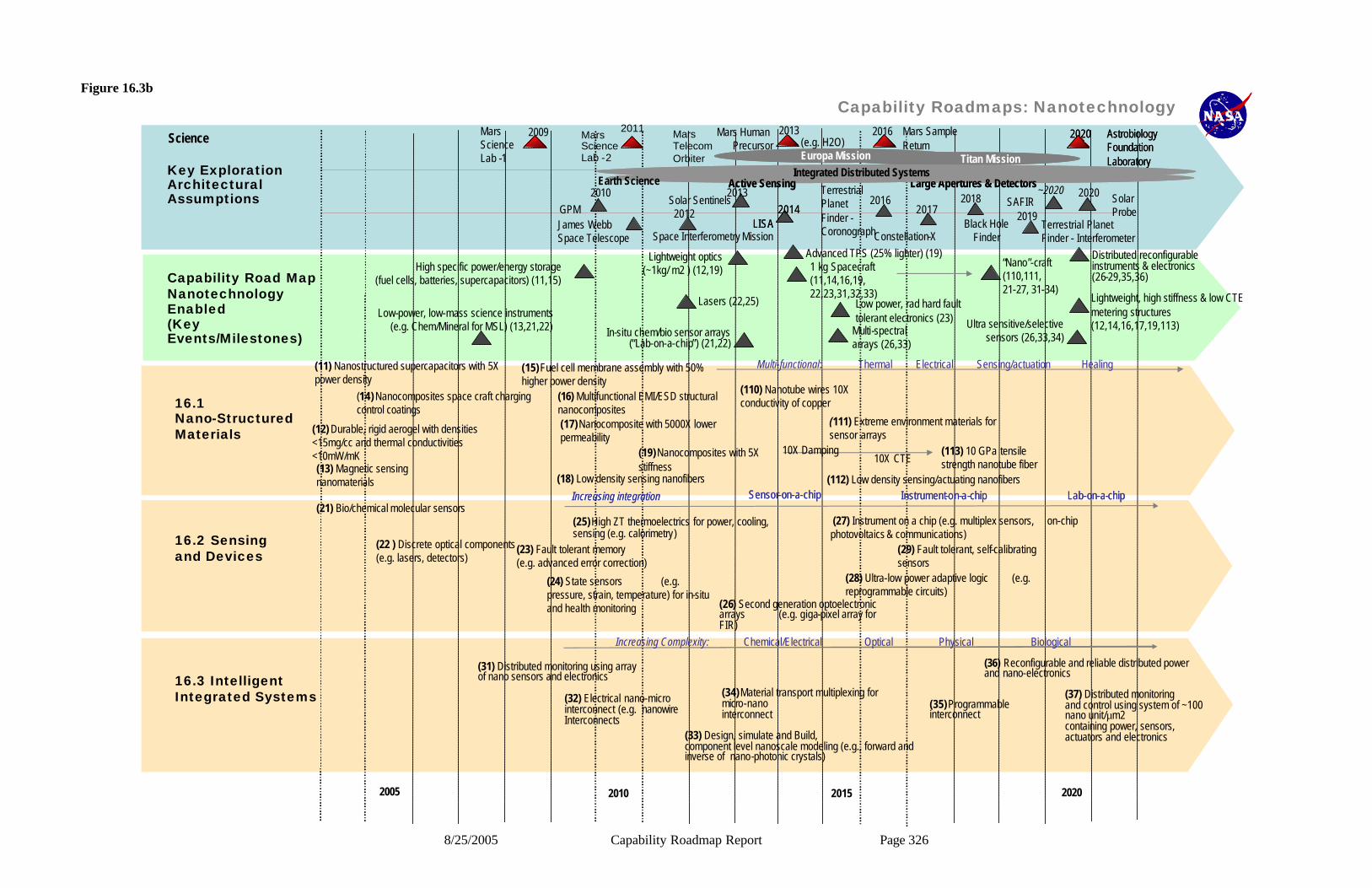
8/25/2005 Capability Roadmap Report Page 326
Click to edit Master title style
16.1 Nano-Structured Materials
16.2 Sensing and Devices
16.3 Intelligent Integrated Systems
Capability Road MapNanotechnologyEnabled(Key Events/Milestones)
Key Exploration Architectural Assumptions
Multi-spectral arrays (26,33)
2005 2010 20202015
(19)Nanocomposites with 5X stiffness
(12) Durable, rigid aerogel with densities <15mg/cc and thermal conductivities <10mW/mK (113) 10 GPa tensile
strength nanotube fiber
High specific power/energy storage(fuel cells, batteries, supercapacitors) (11,15)
Low power, rad hard fault tolerant electronics (23)
(110) Nanotube wires 10X conductivity of copper(14) Nanocomposites space craft charging
control coatings(16) Multifunctional EMI/ESD structural nanocomposites
Lightweight, high stiffness & low CTE metering structures (12,14,16,17,19,113)
(18) Low density sensing nanofibers (112) Low density sensing/actuating nanofibers(13) Magnetic sensing nanomaterials
Advanced TPS (25% lighter) (19)1 kg Spacecraft(11,14,16,19,22,23,31,32,33)
Distributed reconfigurable instruments & electronics (26-29,35,36)
“Nano”-craft (110,111,21-27, 31-34)
Science
Low-power, low-mass science instruments (e.g. Chem/Mineral for MSL) (13,21,22)
(15)Fuel cell membrane assembly with 50% higher power density
(11) Nanostructured supercapacitors with 5X power density
Lightweight optics (~1kg/ m2 ) (12,19)
(17)Nanocomposite with 5000X lower permeability
(111) Extreme environment materials for sensor arrays
In-situ chem/bio sensor arrays (“Lab-on-a-chip”) (21,22)
Ultra sensitive/selective sensors (26,33,34)
Lasers (22,25)
Multi-functional: Thermal Electrical Sensing/actuation Healing
(29) Fault tolerant, self-calibrating sensors
(28) Ultra-low power adaptive logic (e.g. reprogrammable circuits)
(23) Fault tolerant memory (e.g. advanced error correction)
(32) Electrical nano-micro interconnect (e.g. nanowireInterconnects
(34)Material transport multiplexing for micro-nano interconnect
(33) Design, simulate and Build,component level nanoscale modeling (e.g., forward and inverse of nano-photonic crystals)
(35)Programmable interconnect
(31) Distributed monitoring using array of nano sensors and electronics
(37) Distributed monitoring and control using system of ~100 nano unit/µm2 containing power, sensors, actuators and electronics
(25)High ZT thermoelectrics for power, cooling, sensing (e.g. calorimetry)
(27) Instrument on a chip (e.g. multiplex sensors, on-chip photovoltaics & communications)
(21) Bio/chemical molecular sensors
(22 ) Discrete optical components (e.g. lasers, detectors)
(26) Second generation optoelectronic arrays (e.g. giga-pixel array for FIR)
(24) State sensors (e.g. pressure, strain, temperature) for in-situ and health monitoring
Increasing Complexity: Chemical/Electrical Optical Physical Biological
James WebbSpace Telescope
2012
2010GPM
2013Solar Sentinels
Space Interferometry Mission
2014LISA
2014LISA
2016Terrestrial Planet Finder -Coronograph
2017
Constellation-X
2018
Black HoleFinder
2019Terrestrial Planet Finder - Interferometer
2020 SolarProbe
~2020SAFIR
Mars SampleReturn
2016Mars Human Precursor
2013Mars Science Lab -1
2009 Mars Science Lab -2
2011 Mars TelecomOrbiter
AstrobiologyFoundation Laboratory
2020 AstrobiologyFoundation Laboratory
2020
Titan MissionEuropa Mission Titan MissionEuropa Mission
Large Apertures & DetectorsActive Sensing Large Apertures & DetectorsActive SensingEarth ScienceIntegrated Distributed SystemsIntegrated Distributed Systems
(e.g. H2O)
(36) Reconfigurable and reliable distributed power and nano-electronics
Increasing integration Instrument-on-a-chipSensor-on-a-chip Lab-on-a-chipIncreasing integration Instrument-on-a-chipSensor-on-a-chip Lab-on-a-chip
10X Damping10X CTE
Capability Roadmaps: NanotechnologyFigure 16.3b
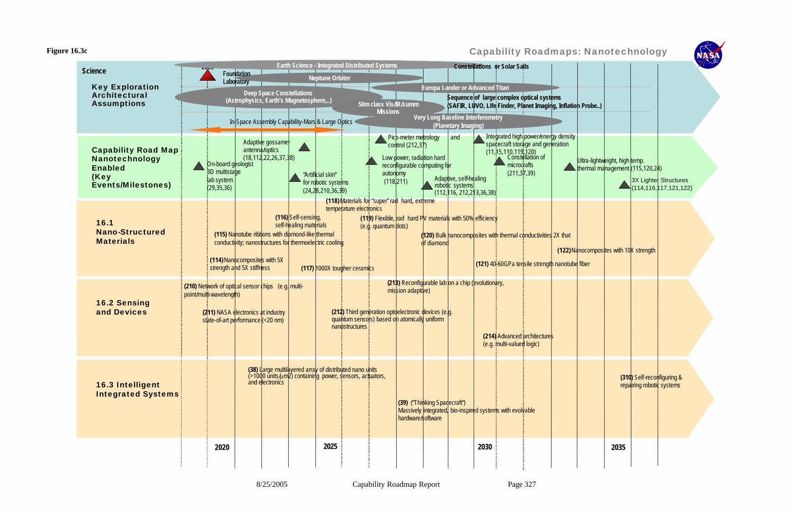
8/25/2005 Capability Roadmap Report Page 327
Click to edit Master title style
16.1 Nano-Structured Materials
16.2 Sensing and Devices
16.3 Intelligent Integrated Systems
Capability Road MapNanotechnologyEnabled(Key Events/Milestones)
Key Exploration Architectural Assumptions
Adaptive, self-healing robotic systems (112,116, 212,213,36,38)
2020 2025 20352030
(118)Materials for “super” rad hard, extreme temperature electronics
(121) 40-60GPa tensile strength nanotube fiber(114)Nanocomposites with 5X strength and 5X stiffness (117) 1000X tougher ceramics
(115) Nanotube ribbons with diamond-like thermal conductivity; nanostructures for thermoelectric cooling
(120) Bulk nanocomposites with thermal conductivities 2X that of diamond
(119) Flexible, rad hard PV materials with 50% efficiency (e.g. quantum dots)
Low power, radiation hard reconfigurable computing for autonomy(118,211)
Integrated high power/energy density spacecraft storage and generation (11,15,110,119,120)
Ultra-lightweight, high temp.thermal management (115,120,24)
3X Lighter Structures (114,116,117,121,122)
On-board geologist3D multistage lab system(29,35,36)
Constellation of microcrafts(211,37,39) “Artificial skin”
for robotic systems(24,28,210,36,39)
Pico-meter metrology and control (212,37)
Deep Space Constellations(Astrophysics, Earth’s Magnetosphere,..) 50m class Vis/IR/summ
MissionsVery Long Baseline Interferometry
(Planetary Imaging)
Sequence of large complex optical systems(SAFIR, LUVO, Life Finder, Planet Imaging, Inflation Probe..)
In-Space Assembly Capability-Mars & Large Optics
ScienceNeptune Orbiter
Europa Lander or Advanced Titan
Mars AstrobiologyFoundation Laboratory
2020 Mars AstrobiologyFoundation Laboratory
2020 Earth Science - Integrated Distributed SystemsEarth Science - Integrated Distributed Systems Constellations or Solar Sails
Adaptive gossamerantenna/optics (18,112,22,26,37,38)
(116) Self-sensing, self-healing materials
(213) Reconfigurable lab on a chip (evolutionary, mission adaptive)
(211) NASA electronics at industry state-of-art performance (<20 nm)
(214) Advanced architectures (e.g. multi-valued logic)
(210) Network of optical sensor chips (e.g. multi-point/multi-wavelength)
(38) Large multilayered array of distributed nano units (>1000 units/µm2) containing power, sensors, actuators, and electronics
(212) Third generation optoelectronic devices (e.g. quantum sensors) based on atomically uniform nanostructures
(39) (“Thinking Spacecraft”) Massively integrated, bio-inspired systems with evolvable hardware/software
(310) Self-reconfiguring & repairing robotic systems
(122)Nanocomposites with 10X strength
Capability Roadmaps: NanotechnologyFigure 16.3c
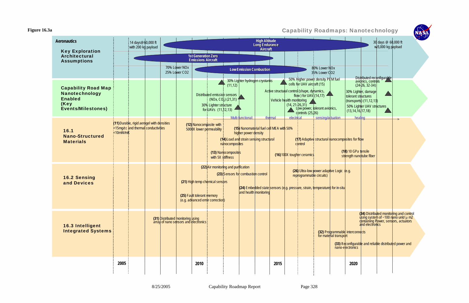
8/25/2005 Capability Roadmap Report Page 328
Click to edit Master title style
16.1 Nano-Structured Materials
16.2 Sensing and Devices
16.3 Intelligent Integrated Systems
Capability Road MapNanotechnologyEnabled(Key Events/Milestones)
Key Exploration Architectural Assumptions
2005 2010 20202015
(12) Nanocomposite with 5000X lower permeability
(16)100X tougher ceramics(13) Nanocomposites with 5X stiffness
(15) Nanomaterial fuel cell MEA with 50% higher power density
(11)Durable, rigid aerogel with densities <15mg/cc and thermal conductivities <10mW/mK
(18) 10 GPa tensile strength nanotube fiber
50% Higher power density PEM fuel cells for UAV aircraft (15)
30% Lighter hydrogen cryotanks (11,12)
50% Lighter UAV structures (13,14,16,17,18)
(14)Load and strain sensing structural nanocomposites
(17) Adaptive structural nanocomposites for flow control
Distributed reconfigurable avionics, controls(24-26, 32-34)
Vehicle health monitoring(14, 21-26,31)
High AltitudeHigh AltitudeLong EnduranceLong Endurance
AircraftAircraft
1st Generation Zero 1st Generation Zero Emissions Aircraft Emissions Aircraft
14 days@60,000 ft with 200 kg payload
30 days @ 60,000 ft w/3,000 kg payload
Low Emission Combustion Low Emission Combustion 70% Lower NOx25% Lower CO2
80% Lower NOx35% Lower CO2
Aeronautics
Multi-functional: thermal electrical sensing/actuation healing
30% Lighter, damage tolerant structures (transports) (11,12,13)
30% Lighter structure for UAVs (11,12,13)
Active structural control (shape, dynamics, flow ) for UAV (14,17)
Low power, tolerant avionics, controls (25,26)
Distributed emission sensors (NOx, CO2) (21,31)
(23) Sensors for combustion control
(22)Air monitoring and purification
(33) Reconfigurable and reliable distributed power and nano-electronics
(32) Programmable interconnects for material transport
(31) Distributed monitoring usingarray of nano sensors and electronics
(34) Distributed monitoring and control using system of ~100 nano unit/ µ m2 containing Power, sensors, actuators and electronics
(26) Ultra-low power adaptive Logic (e.g. reprogrammable circuits)
(25) Fault tolerant memory (e.g. advanced error correction)
(24) Embedded state sensors (e.g. pressure, strain, temperature) for in-situ and health monitoring
(21) High temp chemical sensors
Capability Roadmaps: NanotechnologyFigure 16.3a
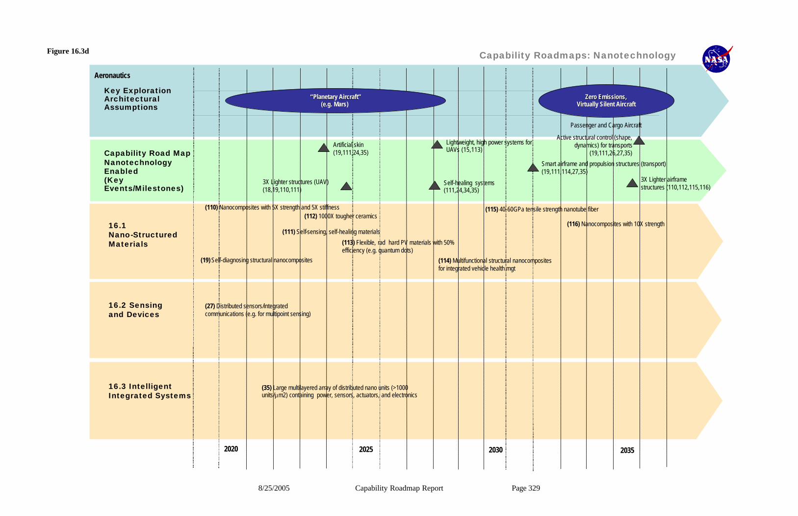
8/25/2005 Capability Roadmap Report Page 329
Click to edit Master title style
16.1 Nano-Structured Materials
16.2 Sensing and Devices
16.3 Intelligent Integrated Systems
Capability Road MapNanotechnologyEnabled(Key Events/Milestones)
Key Exploration Architectural Assumptions
2020
(115) 40-60GPa tensile strength nanotube fiber(110) Nanocomposites with 5X strength and 5X stiffness(112) 1000X tougher ceramics
3X Lighter airframe structures (110,112,115,116)
(19) Self-diagnosing structural nanocomposites (114) Multifunctional structural nanocomposites for integrated vehicle health mgt
Smart airframe and propulsion structures (transport) (19,111,114,27,35)
Self-healing systems(111,24,34,35)
Artificial skin(19,111,24,35)
““Planetary AircraftPlanetary Aircraft””(e.g. Mars) (e.g. Mars)
Zero Emissions,Zero Emissions,Virtually Silent AircraftVirtually Silent Aircraft
Passenger and Cargo Aircraft
Aeronautics
(111) Self-sensing, self-healing materials
3X Lighter structures (UAV) (18,19,110,111)
(113) Flexible, rad hard PV materials with 50% efficiency (e.g. quantum dots)
2025 20352030
Active structural control (shape, dynamics) for transports
(19,111,26,27,35)
(35) Large multilayered array of distributed nano units (>1000 units/µm2) containing power, sensors, actuators, and electronics
(27) Distributed sensors/integrated communications (e.g. for multipoint sensing)
(116) Nanocomposites with 10X strength
Lightweight, high power systems for UAVs (15,113)
Capability Roadmaps: NanotechnologyFigure 16.3d
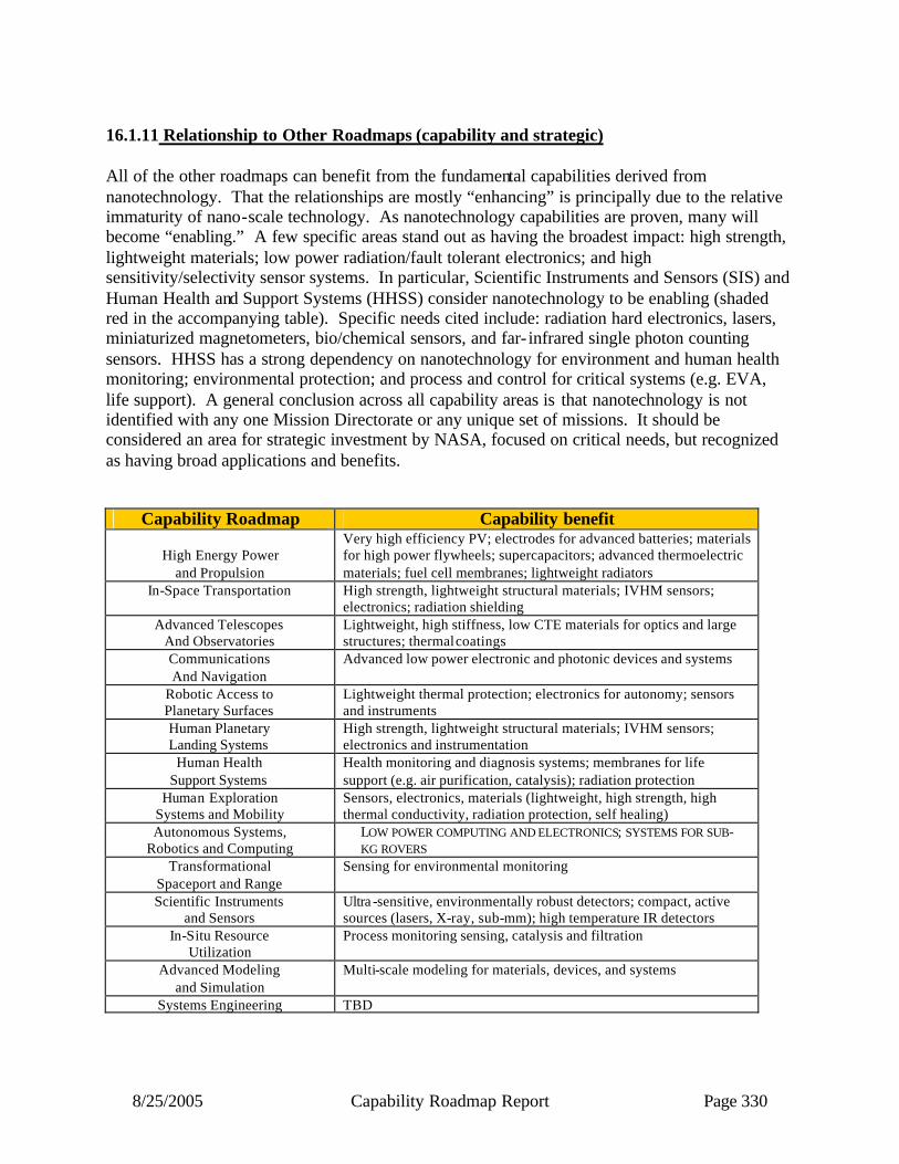
8/25/2005 Capability Roadmap Report Page 330
16.1.11 Relationship to Other Roadmaps (capability and strategic) All of the other roadmaps can benefit from the fundamental capabilities derived from nanotechnology. That the relationships are mostly “enhancing” is principally due to the relative immaturity of nano-scale technology. As nanotechnology capabilities are proven, many will become “enabling.” A few specific areas stand out as having the broadest impact: high strength, lightweight materials; low power radiation/fault tolerant electronics; and high sensitivity/selectivity sensor systems. In particular, Scientific Instruments and Sensors (SIS) and Human Health and Support Systems (HHSS) consider nanotechnology to be enabling (shaded red in the accompanying table). Specific needs cited include: radiation hard electronics, lasers, miniaturized magnetometers, bio/chemical sensors, and far- infrared single photon counting sensors. HHSS has a strong dependency on nanotechnology for environment and human health monitoring; environmental protection; and process and control for critical systems (e.g. EVA, life support). A general conclusion across all capability areas is that nanotechnology is not identified with any one Mission Directorate or any unique set of missions. It should be considered an area for strategic investment by NASA, focused on critical needs, but recognized as having broad applications and benefits.
Capability Roadmap Capability benefit
High Energy Power and Propulsion
Very high efficiency PV; electrodes for advanced batteries; materials for high power flywheels; supercapacitors; advanced thermoelectric materials; fuel cell membranes; lightweight radiators
In-Space Transportation High strength, lightweight structural materials; IVHM sensors; electronics; radiation shielding
Advanced Telescopes And Observatories
Lightweight, high stiffness, low CTE materials for optics and large structures; thermal coatings
Communications And Navigation
Advanced low power electronic and photonic devices and systems
Robotic Access to Planetary Surfaces
Lightweight thermal protection; electronics for autonomy; sensors and instruments
Human Planetary Landing Systems
High strength, lightweight structural materials; IVHM sensors; electronics and instrumentation
Human Health Support Systems
Health monitoring and diagnosis systems; membranes for life support (e.g. air purification, catalysis); radiation protection
Human Exploration Systems and Mobility
Sensors, electronics, materials (lightweight, high strength, high thermal conductivity, radiation protection, self healing)
Autonomous Systems, Robotics and Computing
LOW POWER COMPUTING AND ELECTRONICS; SYSTEMS FOR SUB-KG ROVERS
Transformational Spaceport and Range
Sensing for environmental monitoring
Scientific Instruments and Sensors
Ultra -sensitive, environmentally robust detectors; compact, active sources (lasers, X-ray, sub-mm); high temperature IR detectors
In-Situ Resource Utilization
Process monitoring sensing, catalysis and filtration
Advanced Modeling and Simulation
Multi-scale modeling for materials, devices, and systems
Systems Engineering TBD

8/25/2005 Capability Roadmap Report Page 331
16.1.12 Infrastructure The NASA Centers collectively, have the foundational infrastructure to perform state-of-the-art experimental and theoretical work in nanotechnology. Such work includes synthesis, characterization, modeling and device applications. In addition, the Agency has two world-class facilities for advancing nanoscale technologies:
(1) Ames Research Center’s Columbia Supercomputer, the fastest operational production
machine, consists of 10,240 parallel processors capable of large-scale molecular and super-molecular modeling and simulations;
(2) JPL’s electron beam lithography system, arguably one of the world’s finest, allows for research and fabrication on the nano scale, with a spot size of 4nm.
The Agency has in place four world-class nanotechnology “intellectual” infrastructures in the form of University Research, Engineering and Technologies (URETIs). Each URETI is a consortium of universities (lead by one of them) working with NASA Centers and focusing on a specific nanotechnology area. The focus areas of the four NASA Nanotechnology URETIs are:
(1) Bio- inspired materials (lead: Princeton U.); (2) Biomimetics (lead: UCLA); (3) Nanoelectronics (lead: Purdue); and (4) Nanomaterials for Aerospace (lead: Texas A&M).
Finally, due to the Agency’s membership within the National Nanotechnology Initiative, NASA relies on other relevant non-NASA Federal facilities for specific collaborations. Some examples: NSF (basic science and national nanotechnology facilities); NIH (Human health); NIST (metrology); and DOE (energy systems).

8/25/2005 Capability Roadmap Report Page 332
16.2 Acronym list CBS Capability Breakdown Structure CEV Crew Exploration Vehicle CFC Carbon Fiber Composite CMOS Complementary Metal Oxide Semiconductor CNC Carbon Nanotube Composite CRM Capability Roadmap DOE Department of Energy EVA Extra-Vehicular Activity FIR Far Infrared FOD Foreign Object Damage FPGA Field Programmable Gate Array ITRS International Technology Roadmap for Semiconductors LEO Low Earth Orbit MLI Multi-Layer Insulation PLSS Portable Life Support System NIH National Institutes of Health NIST National Institute of Standards and Technology NNI National Nanotechnology Institute NSET Nanotechnology Science, Engineering and Technology NSTC National Science and Technology Committee PV Photovoltaic TPS Thermal Protection System TRL Technology Readiness Level UAV Unoccupied Air Vehicle URETI University Research, Engineering and Technology Institutes

8/25/2005 Capability Roadmap Report Page 333
Appendix A: Additional Assessment of Nanotechnology Capabilities Nanotechnology enables a broad range of capabilities across all other Capability areas. The following capabilities are in addition to those judged to be most important at this time.
Additional Nanotechnology Capabilities and Status
Capability/Sub-Capability Mission or Roadmap Enabled
Current State of Practice
Development Time
50% Efficient, Low Cost, Flexible Photovoltaics: Photovoltaic arrays based on nano-structures (e.g. quantum dot or quantum rod) are predicted to have achievable efficiencies about 50%. They are also expected to be as inexpensive and lightweight as thin film PV arrays are today.
BROAD EXPLORATION AND SCIENCE MISSIONS, HIGH ALTITUDE LONG ENDURANCE ROBOTIC AIRCRAFT .
Multi-junction arrays are approaching 30% (max <40%), thin film-arrays ~12% (potentially ~20%)
Full potential, 20 years.
Power/Energy Storage: Materials and devices for energy storage and power delivery depend significantly on the surface area available for charge transfer. Nano-scale materials (e.g. carbon nanotubes, nanorods) have >1000X greater areas than any conventional material: 50% lighter proton exchange modules using carbon nanotube membranes; lightweight,carbon nanotube supercapacitors and battery electrodes for safer Li-polymer batteries.
Broad range of Exploration, Science missions
Nafion proton exchange membranes for fuel cells, Li-batteries (<100 Whr,kg)
First use: 5-10 yrs
Biotic/Abiotic Systems: Techniques to exploit the strong connection between biology and nanotechnology; includes biological elements in non-invasive systems and robotic systems for enhanced human health monitoring and human productivity in space.
Human and Robotic missions.
Currently, TRL 2, at most. Artificial retina at low level of resolution has been tested; cell–level drug delivery exists in lab test already.
~15 years
High strength membrane for gossamer structures with aerial densities 10 times lower than current membranes: Through the use of high strength, low density, high dimensional stability nanocomposites (carbon nanotube or other nanoparticles).
Impacts Science (large aperture telescopes, solar sails) and Exploration (habitats).
High strength polymer films.
15-20 years.
Ceramic nanomaterials with 1000-fold increased in toughness over conventional ceramics: Through the use of nanoparticle additions and controlled nanoscale morphology.
Lightweight, damage tolerant structures for Exploration (micro-meteorite protection), Aeronautics (FOD damage resistance, engine containment).
Addition of fibers to ceramics to act as crack arresters.
15-20 Years.
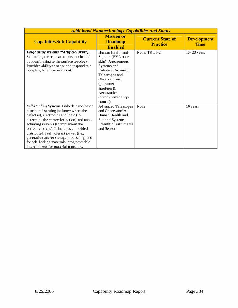
8/25/2005 Capability Roadmap Report Page 334
Additional Nanotechnology Capabilities and Status
Capability/Sub-Capability Mission or Roadmap Enabled
Current State of Practice
Development Time
Large array systems (“Artificial skin”): Sensor-logic circuit-actuators can be laid out conforming to the surface topology. Provides ability to sense and respond to a complex, harsh environment.
Human Health and Support (EVA outer skin), Autonomous Systems and Robotics, Advanced Telescopes and Observatories (gossamer apertures)), Aeronautics (aerodynamic shape control)
None, TRL 1-2 10- 20 years
Self-Healing Systems Embeds nano-based distributed sensing (to know where the defect is), electronics and logic (to determine the corrective action) and nano actuating systems (to implement the corrective steps). It includes embedded distributed, fault tolerant power (i.e., generation and/or storage processing) and for self-healing materials, programmable interconnects for material transport.
Advanced Telescopes and Observatories, Human Health and Support Systems, Scientific Instruments and Sensors
None 10 years