Overview of the Alcator C-MOD research programme
14
Prepared for the U.S. Department of Energy under Contract DE-AC02-76CH03073. Princeton Plasma Physics Laboratory Overview of the Alcator C-MOD Research Program S. Scott, A. Bader, M. Bakhtiari, N. Basse, W. Beck, T. Biewer, S. Bernabei, P. Bonoli, B. Bose, R. Bravenec, I. Bespamyatnov, R. Childs, I. Cziegler, R. Doerner, E. Edlund, D. Ernst, A. Fasoli, M. Ferrara, C. Fiore, T. Fredian, A. Graf, T. Graves, R. Granetz, N. Greenough, M. Greenwald, M. Grimes, O. Grulke, D. Gwinn, R. Harvey, S. Harrison, T.C. Hender, J. Hosea, D.F. Howell, A.E. Hubbard, J.W. Hughes, I. Hutchinson, A. Ince-Cushman, J. Irby, T. Jernigan, D. Johnson, J. Ko, P. Koert, B. LaBombard, A. Kanojia, L. Lin, Y. Lin, B. Lipschultz, J. Liptac, A. Lynn, P. MacGibbon, E. Marmar, K. Marr, M. May, D.R. Mikkelsen, R. McDermott, A. Parisot, R. Parker, C.K. Phillips, P. Phillips, M. Porkolab, M. Reinke, J. Rice, W. Rowan, M. Sampsell, G. Schilling, A. Schmidt, N. Smick, A. Smirnov, J. Snipes, D. Stotler, J. Stillerman, V. Tang, D. Terry, J. Terry, M. Ulrickson, R. Vieira, G.Wallace, D. Whyte, J.R. Wilson, G. Wright, J. Wright, S. Wolfe, S.Wukitch, G. Wurden, H. Yuh, K. Zhurovich, J. Zaks, and S. Zweben November 2007 PPPL-4269 PPPL-4269
Transcript of Overview of the Alcator C-MOD research programme
Prepared for the U.S. Department of Energy under Contract DE-AC02-76CH03073.
Princeton Plasma Physics Laboratory
Overview of the Alcator C-MODResearch Program
S. Scott, A. Bader, M. Bakhtiari, N. Basse, W. Beck, T. Biewer, S. Bernabei, P. Bonoli,B. Bose, R. Bravenec, I. Bespamyatnov, R. Childs, I. Cziegler, R. Doerner, E. Edlund,
D. Ernst, A. Fasoli, M. Ferrara, C. Fiore, T. Fredian, A. Graf, T. Graves, R. Granetz,N. Greenough, M. Greenwald, M. Grimes, O. Grulke, D. Gwinn, R. Harvey, S. Harrison,
T.C. Hender, J. Hosea, D.F. Howell, A.E. Hubbard, J.W. Hughes, I. Hutchinson,A. Ince-Cushman, J. Irby, T. Jernigan, D. Johnson, J. Ko, P. Koert, B. LaBombard,
A. Kanojia, L. Lin, Y. Lin, B. Lipschultz, J. Liptac, A. Lynn, P. MacGibbon, E. Marmar,K. Marr, M. May, D.R. Mikkelsen, R. McDermott, A. Parisot, R. Parker, C.K. Phillips,
P. Phillips, M. Porkolab, M. Reinke, J. Rice, W. Rowan, M. Sampsell, G. Schilling,A. Schmidt, N. Smick, A. Smirnov, J. Snipes, D. Stotler, J. Stillerman, V. Tang, D. Terry,J. Terry, M. Ulrickson, R. Vieira, G.Wallace, D. Whyte, J.R. Wilson, G. Wright, J. Wright,
S. Wolfe, S.Wukitch, G. Wurden, H. Yuh, K. Zhurovich, J. Zaks, and S. Zweben
November 2007
PPPL-4269 PPPL-4269
Princeton Plasma Physics Laboratory Report Disclaimers
Full Legal Disclaimer
This report was prepared as an account of work sponsored by an agency of the United States Government. Neither the United States Government nor any agency thereof, nor any of their employees, nor any of their contractors, subcontractors or their employees, makes any warranty, express or implied, or assumes any legal liability or responsibility for the accuracy, completeness, or any third party’s use or the results of such use of any information, apparatus, product, or process disclosed, or represents that its use would not infringe privately owned rights. Reference herein to any specific commercial product, process, or service by trade name, trademark, manufacturer, or otherwise, does not necessarily constitute or imply its endorsement, recommendation, or favoring by the United States Government or any agency thereof or its contractors or subcontractors. The views and opinions of authors expressed herein do not necessarily state or reflect those of the United States Government or any agency thereof.
Trademark Disclaimer
Reference herein to any specific commercial product, process, or service by trade name, trademark, manufacturer, or otherwise, does not necessarily constitute or imply its endorsement, recommendation, or favoring by the United States Government or any agency thereof or its contractors or subcontractors.
PPPL Report Availability
Princeton Plasma Physics Laboratory:
http://www.pppl.gov/techreports.cfm Office of Scientific and Technical Information (OSTI):
http://www.osti.gov/bridge
Related Links:
U.S. Department of Energy Office of Scientific and Technical Information Fusion Links
IOP PUBLISHING and INTERNATIONAL ATOMIC ENERGY AGENCY NUCLEAR FUSION
Nucl. Fusion 47 (2007) S598–S607 doi:10.1088/0029-5515/47/10/S09
Overview of the Alcator C-MOD researchprogrammeS. Scott1, A. Bader2, M. Bakhtiari3, N. Basse2,a W. Beck2, T. Biewer4,S. Bernabei1, P. Bonoli2, B. Bose2, R. Bravenec5, I. Bespamyatnov5, R. Childs2,I. Cziegler2, R. Doerner6, E. Edlund2, D. Ernst2, A. Fasoli7, M. Ferrara2,C. Fiore2, T. Fredian2, A. Graf8, T. Graves2, R. Granetz2, N. Greenough1,M. Greenwald2, M. Grimes2, O. Grulke9, D. Gwinn10, R. Harvey11, S. Harrison3,T. C. Hender12, J. Hosea1, D. F. Howell12, A. E. Hubbard2, J. W. Hughes2,I. Hutchinson2, A. Ince-Cushman2, J. Irby2, T. Jernigan4, D. Johnson2, J. Ko2,P. Koert2, B. LaBombard2, A. Kanojia2, L. Lin2, Y. Lin2, B. Lipschultz2,J. Liptac2,b, A. Lynn14,c, P. MacGibbon2, E. Marmar2, K. Marr2, M. May13,D. R. Mikkelsen1, R. McDermott2, A. Parisot2, R. Parker2, C. K. Phillips1,P. Phillips5, M. Porkolab2, M. Reinke2, J. Rice2, W. Rowan5, M. Sampsell5,G. Schilling1, A. Schmidt2, N. Smick2, A. Smirnov11, J. Snipes2, D. Stotler1,J. Stillerman2, V. Tang13,d, D. Terry2, J. Terry2, M. Ulrickson14, R. Vieira2,G. Wallace2, D. Whyte2, J. R. Wilson1, G. Wright3, J. Wright2, S. Wolfe2,S. Wukitch2, G. Wurden15, H. Yuh16, K. Zhurovich2, J. Zaks2 and S. Zweben1
1 Princeton Plasma Physics Laboratory, Princeton University, PO Box 451, Princeton, NJ 08543, USA2 Massachusetts Institute of Technology, Plasma Science and Fusion Center, 175 Albany Street, Cambridge,MA 02139, USA3 University of Wisconsin, 1500 Engineering Drive, Madison, WI 53706, USA4 Oak Ridge National Laboratory, Fusion Energy Division, PO Box 2008, Oak Ridge, TN 37831, USA5 University of Texas at Austin, 1 University Station, C1510, Austin, TX 78712, USA6 University of California, San Diego, La Jolla, CA 92093, USA7 Centre de Recherches en Physique des Plasmas Association EURATOM - Confederation Suisse EcolePolytechnique Federale, Station 13 CH-1015 Lausanne, Switzerland8 Department of Physics, University of California, One Shields Avenue, Davis, CA 95616, USA9 Max-Planck-Institut fur Plasmaphysik, Teilinstitut Greifswald, Wendelsteinstraße 1, D-17491 Greifswald,Germany10 Bagley Associates, 7 Bagley Avenue, Lowell, MA 01851, USA11 CompX, PO Box 2672, Del Mar, CA 92014, USA12 EURATOM-UKAEA Fusion Association, Culham Science Centre, Abingdon, OX14 3DB, UK13 Lawrence Livermore National Laboratory, 7000 East Avenue, Livermore, CA 99550, USA14 Fusion Energy Science Program, Sandia National Laboratories, PO Box 5800, MS-1129, Albuquerque,NM 87185, USA15 Los Alamos National Laboratory, PO Box 1663, Los Alamos, NM 87545, USA16 Nova Photonics, Inc., One Oak Place, Princeton, NJ 08540, USA
E-mail: [email protected]
Received 6 February 2007, accepted for publication 11 June 2007Published 18 September 2007Online at stacks.iop.org/NF/47/S598
AbstractAlcator C-MOD has compared plasma performance with plasma-facing components (PFCs) coated with boron toall-metal PFCs to assess projections of energy confinement from current experiments to next-generation burning
a Current address: ABB Switzerland Ltd, Corporate Research, Segelhof-strasse 1 K, CH-5405 Baden 5 Dattwil, Switzerland.b Current address: Intel Corporation, Hillsboro, OR, USA.c Current address: Department of Electrical and Computer Engineering,MSCO1 1100, University of New Mexico, NM 87131, USA.d Current address: Lawrence Livermore National Laboratory, PO Box 808,L-229, Livermore, CA 94551, USA.
0029-5515/07/100598+10$30.00 © 2007 IAEA, Vienna Printed in the UK S598
Overview of the Alcator C-MOD research programme
tokamak plasmas. Low-Z coatings reduce metallic impurity influx and diminish radiative losses leading to higherH-mode pedestal pressure that improves global energy confinement through profile stiffness. RF sheath rectificationalong flux tubes that intersect the RF antenna is found to be a major cause of localized boron erosion and impuritygeneration. Initial lower hybrid current drive (LHCD) experiments (PLH < 900 kW) in preparation for futureadvanced-tokamak studies have demonstrated fully non-inductive current drive at Ip ∼ 1.0 MA with good efficiency,Idrive = 0.4PLH/neoR (MA, MW, 1020 m−3,m). The potential to mitigate disruptions in ITER through massive gas-jet impurity puffing has been extended to significantly higher plasma pressures and shorter disruption times. Thefraction of total plasma energy radiated increases with the Z of the impurity gas, reaching 90% for krypton. Apositive major-radius scaling of the error field threshold for locked modes (Bth/B ∝ R0.68±0.19) is inferred from itsmeasured variation with BT that implies a favourable threshold value for ITER. A phase contrast imaging diagnostichas been used to study the structure of Alfven cascades and turbulent density fluctuations in plasmas with aninternal transport barrier. Understanding the mechanisms responsible for regulating the H-mode pedestal height isalso crucial for projecting performance in ITER. Modelling of H-mode edge fuelling indicates high self-screeningto neutrals in the pedestal and scrape-off layer (SOL), and reproduces experimental density pedestal response tochanges in neutral source, including a weak variation of pedestal height and constant width. Pressure gradients inthe near SOL of Ohmic L-mode plasmas are observed to scale consistently as I 2
p , and show a significant dependenceon X-point topology. Fast camera images of intermittent turbulent structures at the plasma edge show they travelcoherently through the SOL with a broad radial velocity distribution having a peak at about 1% of the ion soundspeed, in qualitative agreement with theoretical models. Fast Dα diagnostics during gas puff imaging show a complexbehaviour of discrete ELMs, starting with an n ≈ 10 precursor oscillation followed by a rapid primary ejection asthe pedestal crashes and then multiple, slower secondary ejections.
PACS numbers: 52.25.Vy, 52.35.Bj, 52.35.Ra, 52.40.Hf, 52.55.−s, 52.55.Fa, 52.55.Wq
1. Introduction
Recent research on the high-field, high-density divertedAlcator C-MOD tokamak has focused on the plasma physicsand plasma engineering required for ITER and for attractivefusion reactors. C-MOD is prototypical of ITER in severalkey respects including toroidal magnetic field, equilibratedions and electrons, plasma density, power density in thescrape-off-layer (SOL), low momentum input, high-Z plasma-facing components (PFCs), divertor neutral opacity and long-pulse length compared with the skin time. The paperis organized as follows: sections 2 and 3 summarize themajor thrusts of the C-MOD 2005-6 campaigns comprisingperformance studies with all-metal walls and initial lowerhybrid current drive (LHCD) experiments. Recent disruptionmitigation studies involving massive gas puffs are describedin section 4. Experiments to infer the major-radius scalingof the error field threshold for locked modes are reportedin section 5. Sections 6 and 7 describe new results fromthe phase contrast imaging (PCI) diagnostic related to thestucture of Alfven Cascades and the wavenumber spectrumof trapped electron mode (TEM) turbulence. The nextfour sections cover recent progress in the physics of theedge plasma. New studies of the scaling of pressuregradients in the H-mode pedestal and SOL are summarizedin sections 8 and 9. Sections 10 and 11 report new resultsin imaging turbulence in the edge plasma and measurementsof the dynamics of edge localized modes. Planned facilityupgrades to C-MOD over the next two years are described insection 12.
2. Performance with all-metal walls versus low-Zcoatings
Tungsten has been selected as the primary material for PFCs inITER and fusion reactors based on its low tritium retention, lowerosion rate, and low neutron damage rate. High-Z metallicPFCs including molybdenum and tungsten have hydrogenrecycling and radiative properties that differ substantially fromlow-Z PFCs (carbon, beryllium) and low-Z PFCs coatings(boron, beryllium, lithium). Most of the world’s divertorand confinement database has been developed in tokamakswith low-Z PFCs or low-Z PFCs coatings (with ASDEX [1]currently pursuing an all-tungsten PFCs environment), butcarbon has been relegated to a small fraction of the PFCssurfaces in ITER and none in a high-fluence demonstrationreactor due to concerns related to tritium retention anderosion.
Until recently, the PFCs environment in C-MOD has beenmolybdenum coated with a thin layer of boron, plus boron-nitride protective tiles near the RF antennas. In C-MOD, theboron layer is replenished periodically using a low-temperatureelectron cyclotron plasma discharge fuelled with diborane gas.This ‘boronization’ process is typically carried out overnight,depositing about 200 nm of boron over a period of 10–12 h,and the resonance location can be swept from the inner wallto beyond the outer limiters by scanning the toroidal field.The deposition location can also be localized radially byimposing a small variation in toroidal field. Prior to the 2005experimental campaign, boron was removed from all PFCsand the boron-nitride tiles were replaced with molybdenumtiles to allow a direct comparison of plasma performance withand without a boron coating, yielding a surface concentration
S599
S. Scott et al
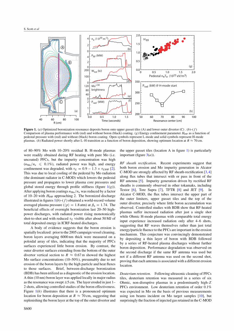
Figure 1. (a) Optimized boronization resonance deposits boron onto upper gusset tiles (A) and lower outer divertor (C) . (b)–(f )Comparison of plasma performance with (red) and without boron (black) coating. (g) Energy confinement parameter H89P as a function ofpedestal pressure with (red) and without (black) boron coating. Open symbols represent L-mode and solid symbols represent H-modeplasmas. (h) Radiated power shortly after L–H transition as a function of boron deposition, showing optimum location at R ≈ 70 cm.
of 80–90% Mo with 10–20% residual B. H-mode plasmaswere readily obtained during RF heating with pure Mo (i.e.uncoated) PFCs, but the impurity concentration was high(nMo/ne � 0.1%), radiated power was high, and energyconfinement was degraded, with τE = 0.9 − 1.3 × τE89P [2].This was due to local cooling of the pedestal by Mo radiation(the dominant radiator in C-MOD) which lowers the pedestalpressure and propagates to lower plasma core pressures andglobal stored energy through profile stiffness (figure 1(g)).After applying boron coatings nMo/ne was reduced by a factorof 10–20 with H89P approaching 2. The boronized dischargeillustrated in figures 1(b)–(f ) obtained a world-record volumeaveraged plasma pressure (〈p〉 = 1.8 atm) at βn = 1.74. Thebeneficial effects of overnight boronization last 20–50 high-power discharges, with radiated power rising monotonicallyshot-to-shot and with reduced τE visible after about 50 MJ oftotal deposited energy in ICRF-heated discharges.
A body of evidence suggests that the boron erosion isspatially localized: prior to the 2005 campaign vessel cleaning,boron layers averaging 6000 nm thick were measured on apoloidal array of tiles, indicating that the majority of PFCssurfaces experienced little boron erosion. By contrast, theouter divertor surfaces extending from the bottom of the outerdivertor vertical section to R ≈ 0.67 m showed the highestMo surface concentrations (10–50%), presumably due to neterosion of the boron layers by the high particle and heat fluxesto those surfaces. Brief, between-discharge boronization(BDB) has been utilized as a diagnostic of the erosion location.A thin (10 nm) boron layer was applied locally in major radiusas the resonance was swept ±5 cm. The layer eroded in just 1–2 shots, allowing controlled studies of the boron effectiveness.Figure 1(h) illustrates that there is a pronounced optimumlocation for boron deposition at R ≈ 70 cm, suggesting thatreplenishing the boron layer at the top of the outer divertor and
the upper gusset tiles (location A in figure 1) is particularlyimportant (figure 3(a)).
RF sheath rectification. Recent experiments suggest thatboth boron erosion and Mo impurity generation in AlcatorC-MOD are strongly affected by RF sheath-rectification [3,4]along flux tubes that intersect with or pass in front of theRF antenna [5]. Impurity generation driven by rectified RFsheaths is commonly observed in other tokamaks, includingTextor [6], Tore Supra [7], TFTR [8] and JET [9]. InAlcator C-MOD, the flux tubes intersect the upper part ofthe outer limiters, upper gusset tiles and the top of theouter divertor, precisely where little boron accumulation wasobserved. Controlled studies with BDB show that RF-heatedplasmas suffer increased radiation after just a single shotwhile Ohmic H-mode plasmas with comparable total energyinput experience increased radiation only after 4–6 shots,suggesting that RF waves themselves rather than just totalenergy/particle fluence to the PFCs are important in the erosionmechanism. This conjecture was convincingly demonstratedby depositing a thin layer of boron with BDB followedby a series of RF-heated plasma discharges without furtherboron deposition. Performance degradation was observed onthe second discharge if the same RF antenna was used butnot if a different RF antenna was used on the second shot,proving that each antenna is associated with a different erosionlocation.
Deuterium retention. Following ultrasonic cleaning of PFCstiles, deuterium retention was measured in a series of sixOhmic, non-disruptive plasmas in a predominantly high-ZPFCs environment. Low deuterium retention of order 0.1%was expected in Mo on the basis of previous measurementsusing ion beams incident on Mo target samples [10], butsurprisingly the fraction of injected gas retained in the C-MOD
S600
Overview of the Alcator C-MOD research programme
0.0
0.2
0.4
0.6
0.8
1.0
1.2
0.0 0.1 0.2 0.3
∆V /
V
PLH / neIp Ro (W m-2 / 1019 A)
(a)
(c)
(d)
(e)
(f ) (g)
(b)
n20 Ip (MA) R(m)
PLH (MW)= 0.4
neo (1019 m-3)Ip (MA)
PLH (MW)
Zeff
Teo (keV)
Vloop (V)
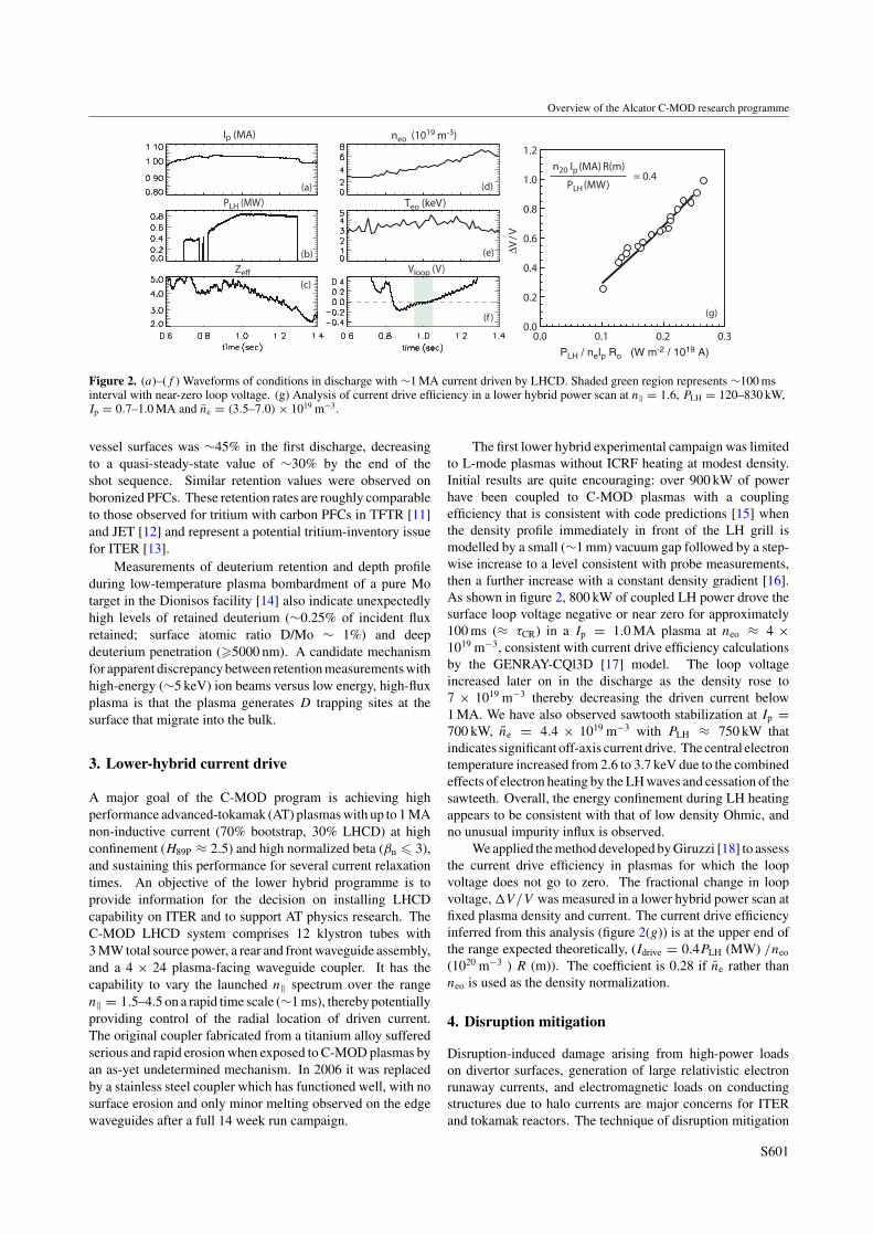
Figure 2. (a)–(f ) Waveforms of conditions in discharge with ∼1 MA current driven by LHCD. Shaded green region represents ∼100 msinterval with near-zero loop voltage. (g) Analysis of current drive efficiency in a lower hybrid power scan at n‖ = 1.6, PLH = 120–830 kW,Ip = 0.7–1.0 MA and ne = (3.5–7.0) × 1019 m−3.
vessel surfaces was ∼45% in the first discharge, decreasingto a quasi-steady-state value of ∼30% by the end of theshot sequence. Similar retention values were observed onboronized PFCs. These retention rates are roughly comparableto those observed for tritium with carbon PFCs in TFTR [11]and JET [12] and represent a potential tritium-inventory issuefor ITER [13].
Measurements of deuterium retention and depth profileduring low-temperature plasma bombardment of a pure Motarget in the Dionisos facility [14] also indicate unexpectedlyhigh levels of retained deuterium (∼0.25% of incident fluxretained; surface atomic ratio D/Mo ∼ 1%) and deepdeuterium penetration (�5000 nm). A candidate mechanismfor apparent discrepancy between retention measurements withhigh-energy (∼5 keV) ion beams versus low energy, high-fluxplasma is that the plasma generates D trapping sites at thesurface that migrate into the bulk.
3. Lower-hybrid current drive
A major goal of the C-MOD program is achieving highperformance advanced-tokamak (AT) plasmas with up to 1 MAnon-inductive current (70% bootstrap, 30% LHCD) at highconfinement (H89P ≈ 2.5) and high normalized beta (βn � 3),and sustaining this performance for several current relaxationtimes. An objective of the lower hybrid programme is toprovide information for the decision on installing LHCDcapability on ITER and to support AT physics research. TheC-MOD LHCD system comprises 12 klystron tubes with3 MW total source power, a rear and front waveguide assembly,and a 4 × 24 plasma-facing waveguide coupler. It has thecapability to vary the launched n‖ spectrum over the rangen‖ = 1.5–4.5 on a rapid time scale (∼1 ms), thereby potentiallyproviding control of the radial location of driven current.The original coupler fabricated from a titanium alloy sufferedserious and rapid erosion when exposed to C-MOD plasmas byan as-yet undetermined mechanism. In 2006 it was replacedby a stainless steel coupler which has functioned well, with nosurface erosion and only minor melting observed on the edgewaveguides after a full 14 week run campaign.
The first lower hybrid experimental campaign was limitedto L-mode plasmas without ICRF heating at modest density.Initial results are quite encouraging: over 900 kW of powerhave been coupled to C-MOD plasmas with a couplingefficiency that is consistent with code predictions [15] whenthe density profile immediately in front of the LH grill ismodelled by a small (∼1 mm) vacuum gap followed by a step-wise increase to a level consistent with probe measurements,then a further increase with a constant density gradient [16].As shown in figure 2, 800 kW of coupled LH power drove thesurface loop voltage negative or near zero for approximately100 ms (≈ τCR) in a Ip = 1.0 MA plasma at neo ≈ 4 ×10¹⁹ m−3, consistent with current drive efficiency calculationsby the GENRAY-CQl3D [17] model. The loop voltageincreased later on in the discharge as the density rose to7 × 1019 m−3 thereby decreasing the driven current below1 MA. We have also observed sawtooth stabilization at Ip =700 kW, ne = 4.4 × 10¹⁹ m−3 with PLH ≈ 750 kW thatindicates significant off-axis current drive. The central electrontemperature increased from 2.6 to 3.7 keV due to the combinedeffects of electron heating by the LH waves and cessation of thesawteeth. Overall, the energy confinement during LH heatingappears to be consistent with that of low density Ohmic, andno unusual impurity influx is observed.
We applied the method developed by Giruzzi [18] to assessthe current drive efficiency in plasmas for which the loopvoltage does not go to zero. The fractional change in loopvoltage, �V/V was measured in a lower hybrid power scan atfixed plasma density and current. The current drive efficiencyinferred from this analysis (figure 2(g)) is at the upper end ofthe range expected theoretically, (Idrive = 0.4PLH (MW) /neo
(1020 m−3 ) R (m)). The coefficient is 0.28 if ne rather thanneo is used as the density normalization.
4. Disruption mitigation
Disruption-induced damage arising from high-power loadson divertor surfaces, generation of large relativistic electronrunaway currents, and electromagnetic loads on conductingstructures due to halo currents are major concerns for ITERand tokamak reactors. The technique of disruption mitigation
S601

S. Scott et al
ZGas
He Ne Ar Kr
0
40
80
120
∆Tsu
rfac
e (K
) af
ter 0
.2 s
(c)
ZGas
I hal
o/
I p
0.20
0.25
0.15
0.10
0.0
unmitigated(b)
He Ne Ar KrHe Ne Ar Kr
20
01 1 2 5 10 20 50 1 2 5 10 20 502 5 10 20 50
40
60
80
100W
rad
/ W
(%
)
ZGas
(a)
Figure 3. (a) Fraction of total power radiated during the disruption; (b) normalized halo current versus atomic number of mitigating gas; (c)rise in surface temperature at the outer lower divertor surface following disruption.
through massive gas-jet impurity puffing originally developedon DIII-D [19] has been extended to significantly higherplasma pressures and shorter disruption times. An ORNLfast-response valve delivered short, massive puffs of helium,neon, argon, or krypton gas to a delivery nozzle near the outerplasma edge. As shown in figure 3(a), the fraction of totalplasma energy radiated increased with Z of the impurity gas,reaching 90% for krypton [20]. The increased radiated powercools the plasma during the current quench and additionallythe impurity increases Zeff , both of which decrease the L/R
quench time. Consequently, the disruption-migitated plasmahas less time to move vertically before contacting the toruswall, thereby reducing the disruption halo currents by up to∼50% (figure 3(b)). Infrared camera images of the outboarddivertor tiles show less surface heating in migitated disruptions(figure 3(c)), consistent with the loss of most of the plasmaenergy to isotropic radiation. Studies of disruption mitigationwith mixtures of helium and argon show promise in combiningthe favourable radiative properties of a high-Z gas with therapid transit of helium through the gas delivery system, whichis limited by its thermal speed.
High speed imaging of the gas-jet plumes show thatimpurity neutrals do not penetrate deeply into the plasma andinitially cool just the periphery of the plasma. Nevertheless,within a few hundred microseconds some impurity ions appearin the plasma core and the core temperature decreases on thesame time scale. NIMROD MHD simulations indicate thatthe initial edge cooling triggers rapid growth of 2/1 and 1/1tearing modes resulting in a large stochastic region that mixesimpurity ions into the core [21].
5. Scaling of the locked-mode threshold
A major uncertainty for projecting the error field thresholdfor locked modes on ITER is its scaling with major radius.The error field scaling is typically represented as a power law[22], Berr/Bt ∝ nαnBαB qαq RαR . Dimensional scaling imposesthe constraint αR = 2αn + 1.25αB and experiments haveestablished that αn = 1, thus a knowledge of the scaling withtoroidal field (αB) also determines the scaling with machinesize. Unfortunately, scaling experiments in C-MOD, JET,DIII-D, and COMPASS-D have yielded disparate values ofαB [23, 24]. C-MOD executed a controlled toroidal field scanat fixed plasma shape (lower single null), fixed q95 = 3.5,
BT (Tesla)0 2 4 6 8 10
0.00
0.05
0.10
0.15
0.20
0.25
B = -1.06 ± 0.15
B /
neB
T (
10-2
3 m
-3)
~
α
Figure 4. Scaling of error field required for mode-locking as afunction of BT.
n/nG = 0.18. On each discharge, the error field imposed byexternal coils (predominantly m/n = 1/1, 2/1 with small 3/1component) was ramped in magnitude until a locked modewas identified from cessation of sawteeth and an n = 1magnetic signature. As shown in figure 4 the data are wellfit by αB = −1.06 ± 0.15 which implies a major-radiusscaling αR = 0.68 ± 0.19 that extrapolates to a thresholdB21/B ≈ 0.9 × 10⁻⁴ in ITER at the density expected in itsOhmic phase (2×10¹⁹ m−3) prior to the application of auxiliaryheating. This is a favourable result in that the original coilcontrol system for ITER was designed to reduce the error fieldto Berr/B ∼ 2 × 10⁻⁵.
6. Alfven cascades
The PCI system [25] and the magnetic pick-up coils arebeing used on Alcator C-MOD to study the physics of Alfveneigenmodes. Of particular interest are the Alfven cascades,core-localized modes that exist in reversed-shear plasmas[26,27]. These modes can be driven by the fast ion populationfrom hydrogen minority ion cyclotron heating and are verysensitive to small changes in the minimum of the q profileresulting in a frequency chirping as the current diffuses.Modelling with the ideal MHD code NOVA-K [28] is beingused to model the frequency characteristics of these modes and
S602
Overview of the Alcator C-MOD research programme
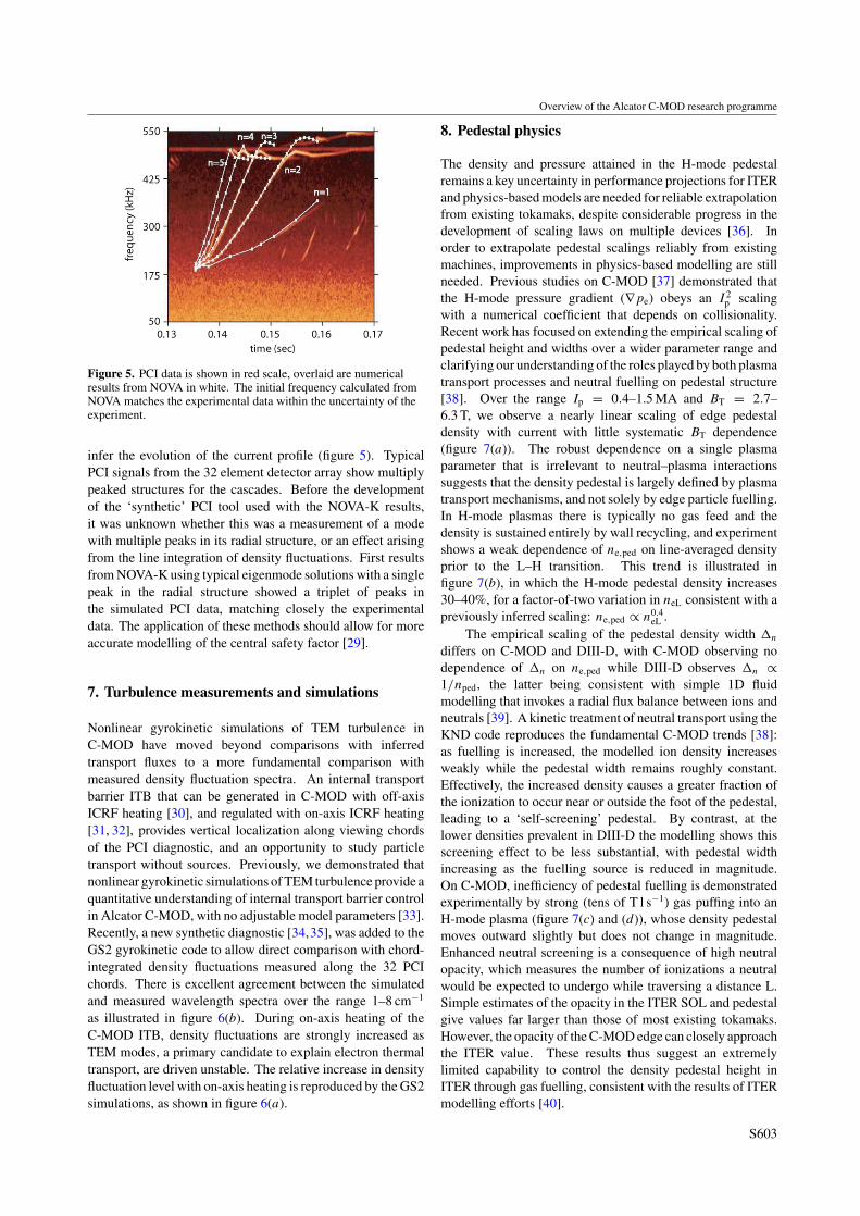
Figure 5. PCI data is shown in red scale, overlaid are numericalresults from NOVA in white. The initial frequency calculated fromNOVA matches the experimental data within the uncertainty of theexperiment.
infer the evolution of the current profile (figure 5). TypicalPCI signals from the 32 element detector array show multiplypeaked structures for the cascades. Before the developmentof the ‘synthetic’ PCI tool used with the NOVA-K results,it was unknown whether this was a measurement of a modewith multiple peaks in its radial structure, or an effect arisingfrom the line integration of density fluctuations. First resultsfrom NOVA-K using typical eigenmode solutions with a singlepeak in the radial structure showed a triplet of peaks inthe simulated PCI data, matching closely the experimentaldata. The application of these methods should allow for moreaccurate modelling of the central safety factor [29].
7. Turbulence measurements and simulations
Nonlinear gyrokinetic simulations of TEM turbulence inC-MOD have moved beyond comparisons with inferredtransport fluxes to a more fundamental comparison withmeasured density fluctuation spectra. An internal transportbarrier ITB that can be generated in C-MOD with off-axisICRF heating [30], and regulated with on-axis ICRF heating[31, 32], provides vertical localization along viewing chordsof the PCI diagnostic, and an opportunity to study particletransport without sources. Previously, we demonstrated thatnonlinear gyrokinetic simulations of TEM turbulence provide aquantitative understanding of internal transport barrier controlin Alcator C-MOD, with no adjustable model parameters [33].Recently, a new synthetic diagnostic [34,35], was added to theGS2 gyrokinetic code to allow direct comparison with chord-integrated density fluctuations measured along the 32 PCIchords. There is excellent agreement between the simulatedand measured wavelength spectra over the range 1–8 cm−1
as illustrated in figure 6(b). During on-axis heating of theC-MOD ITB, density fluctuations are strongly increased asTEM modes, a primary candidate to explain electron thermaltransport, are driven unstable. The relative increase in densityfluctuation level with on-axis heating is reproduced by the GS2simulations, as shown in figure 6(a).
8. Pedestal physics
The density and pressure attained in the H-mode pedestalremains a key uncertainty in performance projections for ITERand physics-based models are needed for reliable extrapolationfrom existing tokamaks, despite considerable progress in thedevelopment of scaling laws on multiple devices [36]. Inorder to extrapolate pedestal scalings reliably from existingmachines, improvements in physics-based modelling are stillneeded. Previous studies on C-MOD [37] demonstrated thatthe H-mode pressure gradient (∇pe) obeys an I 2
p scalingwith a numerical coefficient that depends on collisionality.Recent work has focused on extending the empirical scaling ofpedestal height and widths over a wider parameter range andclarifying our understanding of the roles played by both plasmatransport processes and neutral fuelling on pedestal structure[38]. Over the range Ip = 0.4–1.5 MA and BT = 2.7–6.3 T, we observe a nearly linear scaling of edge pedestaldensity with current with little systematic BT dependence(figure 7(a)). The robust dependence on a single plasmaparameter that is irrelevant to neutral–plasma interactionssuggests that the density pedestal is largely defined by plasmatransport mechanisms, and not solely by edge particle fuelling.In H-mode plasmas there is typically no gas feed and thedensity is sustained entirely by wall recycling, and experimentshows a weak dependence of ne,ped on line-averaged densityprior to the L–H transition. This trend is illustrated infigure 7(b), in which the H-mode pedestal density increases30–40%, for a factor-of-two variation in neL consistent with apreviously inferred scaling: ne,ped ∝ n0.4
eL .The empirical scaling of the pedestal density width �n
differs on C-MOD and DIII-D, with C-MOD observing nodependence of �n on ne,ped while DIII-D observes �n ∝1/nped, the latter being consistent with simple 1D fluidmodelling that invokes a radial flux balance between ions andneutrals [39]. A kinetic treatment of neutral transport using theKND code reproduces the fundamental C-MOD trends [38]:as fuelling is increased, the modelled ion density increasesweakly while the pedestal width remains roughly constant.Effectively, the increased density causes a greater fraction ofthe ionization to occur near or outside the foot of the pedestal,leading to a ‘self-screening’ pedestal. By contrast, at thelower densities prevalent in DIII-D the modelling shows thisscreening effect to be less substantial, with pedestal widthincreasing as the fuelling source is reduced in magnitude.On C-MOD, inefficiency of pedestal fuelling is demonstratedexperimentally by strong (tens of T l s−1) gas puffing into anH-mode plasma (figure 7(c) and (d)), whose density pedestalmoves outward slightly but does not change in magnitude.Enhanced neutral screening is a consequence of high neutralopacity, which measures the number of ionizations a neutralwould be expected to undergo while traversing a distance L.Simple estimates of the opacity in the ITER SOL and pedestalgive values far larger than those of most existing tokamaks.However, the opacity of the C-MOD edge can closely approachthe ITER value. These results thus suggest an extremelylimited capability to control the density pedestal height inITER through gas fuelling, consistent with the results of ITERmodelling efforts [40].
S603

S. Scott et al
|n|2 (PCI)~
GS2
time (sec)0.9 1.0 1.1 1.2 1.3
off-axis
on-axis
PRF
0.0
1.5
3.0M
W0
1
2
3
4
A.U
.
8
Wavenumber kR (cm-1)
0 2 4 60.0
0.1
0.2
0.3
0.4
0.5
PCI
simulated spectrum
(b)|n|2 ~
A.U
.
(a) on+off axisRF-heating
Figure 6. (a) Time history of density fluctuation level when on-axis ICRF power is applied to a plasma with an internal transport barriergenerated by off-axis ICRF heating. Red points represent the fluctuation level computed by GS2. (b) Comparison of measured andsimulated k-spectrum at 1.22 s, when RF provided both on- and off-axis heating.
Pedestal density
0.6 0.8 1.0 1.2 1.4 1.6
Line density during L-mode (1020 m-2)
1
2
3
1020
m-3
(b)
0.0 0.5 1.0 1.5
Ip (MA)
0
1
2
3
4 Pedestal density
1020
m-3
(a)
3
R - RLCFS
Core
SO
LS
OL
ne
Te
Puffed
Unpuffed
1020
m-3
keV
0-5-10-150
0.2
0.4
0
1
2
(c)
(d)
SO
L
Figure 7. (a) Scaling of pedestal density with Ip. (b) Scaling of pedestal density with density in preceding L-mode phase. (c)–(d) EdgeThomson scattering profiles of electron density and temperature in 0.81 MA H-mode plasma before and during strong D2 puffing (tens ofT l s−1) at the inner wall. The density pedestal shifts radially outward but the height remains essentially unchanged.
9. SOL phase space
Previous analysis [41] of scanning Langmuir–Mach probe datashowed that pressure gradients in the SOL of Ohmic L-modedischarges scale as I 2
p (similar to the scaling of edge pedestalpressure in H-mode plasmas) and that the pressure gradientsclamp at similar values of the MHD ballooning parameterαMHD = q2Rβ/Lpe when the normalized collisionalityparameter αd defined in [41] (αd ∝ λ
1/2e /(qR3/4L1.4
⊥ )) isheld fixed. Similar trends are observed in ASDEX-Upgrade,which finds that the pressure gradient e-folding length andheat diffusivity in the H-mode edge scales as LnTe ∼ n/I 2
p[42, 43] and that the overall edge behaviour is consistent witha critical-gradient transport paradigm [44]. Over a wide rangein machine parameters BT, Ip and ne, the observed SOLstates are observed to cluster around a narrow band in thetwo-dimensional space (αMHD, αd) as would be expected fromelectromagnetic fluid drift turbulence (EMFDT). Comparingprobe measurements on the low and high-field SOLs revealedthat the observed large SOL flows are caused by ballooning-like transport that dumps larger particle fluxes into the low-field region, thereby generating a density imbalance thatdrives a helical flow in the SOL toward the high-fieldside.
Recent density scans with 0.1 < n/nG < 0.5 overan extended range of Ip and BT (0.4–1.1 MA, 2.7–5.8 T)
have focused on the effect of the X-point topology on theSOL pressure gradients [45]. As shown in figure 8(a),the SOL pressure gradients continue to scale consistentlyas I 2
p , but with a numerical value that depends on theX-point topology, with higher gradients attained in the LSNconfiguration. For a given X-point configuration, data fromdifferent plasma currents collapse into a narrow band whenplotted in EMFDT phase space (confirming the dominant I 2
pscaling), but the LSN and USN datasets form two separatebands, with lower null achieving higher values of αMHD
(figure 8(b)). As illustrated in figure 8(c), the SOL plasmaflows are dramatically different in the LSN versus USNconfigurations, and the range of collisionality parameter αd
where the LSN obtains higher αMHD corresponds to the regionwhere there is a significant difference in the parallel Machnumber on the low-field side. This indicates that co-currentflows in the SOL are associated with higher pressure gradients,and suggests that flow is another controlling variable in theEMFDT phase space (αMHD, αD, M). Recent experimentswith reversed BT and Ip in USN plasmas confirm theseresults.
10. Imaging of turbulence with gas puffs
Electrostatic turbulence in the SOL of C-MOD has beenmeasured [46] using 1D and 2D gas puff imaging (GPI)
S604
Overview of the Alcator C-MOD research programme
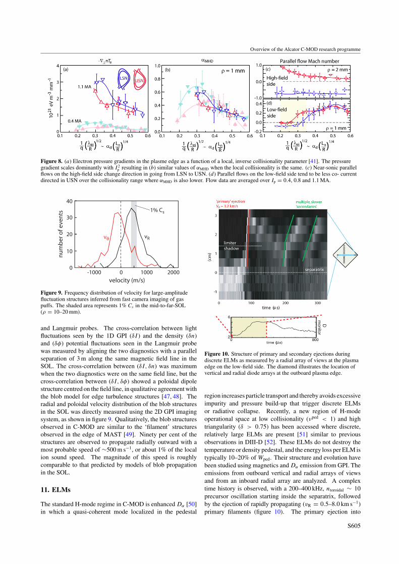
Figure 8. (a) Electron pressure gradients in the plasme edge as a function of a local, inverse collisionality parameter [41]. The pressuregradient scales dominantly with I 2
p resulting in (b) similar values of αMHD when the local collisionality is the same. (c) Near-sonic parallelflows on the high-field side change direction in going from LSN to USN. (d) Parallel flows on the low-field side tend to be less co- currentdirected in USN over the collisionality range where αMHD is also lower. Flow data are averaged over Ip = 0.4, 0.8 and 1.1 MA.
Figure 9. Frequency distribution of velocity for large-amplitudefluctuation structures inferred from fast camera imaging of gaspuffs. The shaded area represents 1% Cs in the mid-to-far-SOL(ρ = 10–20 mm).
and Langmuir probes. The cross-correlation between lightfluctuations seen by the 1D GPI (δI ) and the density (δn)and (δφ) potential fluctuations seen in the Langmuir probewas measured by aligning the two diagnostics with a parallelseparation of 3 m along the same magnetic field line in theSOL. The cross-correlation between (δI, δn) was maximumwhen the two diagnostics were on the same field line, but thecross-correlation between (δI, δφ) showed a poloidal dipolestructure centred on the field line, in qualitative agreement withthe blob model for edge turbulence structures [47, 48]. Theradial and poloidal velocity distribution of the blob structuresin the SOL was directly measured using the 2D GPI imagingsystem, as shown in figure 9. Qualitatively, the blob structuresobserved in C-MOD are similar to the ‘filament’ structuresobserved in the edge of MAST [49]. Ninety per cent of thestructures are observed to propagate radially outward with amost probable speed of ∼500 m s−1, or about 1% of the localion sound speed. The magnitude of this speed is roughlycomparable to that predicted by models of blob propagationin the SOL.
11. ELMs
The standard H-mode regime in C-MOD is enhanced Dα [50]in which a quasi-coherent mode localized in the pedestal
µ
µ
Figure 10. Structure of primary and secondary ejections duringdiscrete ELMs as measured by a radial array of views at the plasmaedge on the low-field side. The diamond illustrates the location ofvertical and radial diode arrays at the outboard plasma edge.
region increases particle transport and thereby avoids excessiveimpurity and pressure build-up that trigger discrete ELMsor radiative collapse. Recently, a new region of H-modeoperational space at low collisionality (νped < 1) and hightriangularity (δ > 0.75) has been accessed where discrete,relatively large ELMs are present [51] similar to previousobservations in DIII-D [52]. These ELMs do not destroy thetemperature or density pedestal, and the energy loss per ELM istypically 10–20% of Wped. Their structure and evolution havebeen studied using magnetics and Dα emission from GPI. Theemissions from outboard vertical and radial arrays of viewsand from an inboard radial array are analyzed. A complextime history is observed, with a 200–400 kHz, ntoroidal ∼ 10precursor oscillation starting inside the separatrix, followedby the ejection of rapidly propagating (vR = 0.5–8.0 km s−1)primary filaments (figure 10). The primary ejection into
S605
S. Scott et al
the outboard SOL is coincident with the onset of ashort-lived 0.5–1 MHz magnetic oscillation. This initialevolution is followed by multiple slower secondary filamentejections.
12. Facility upgrades and future plans
Over the next two years, a number of facility upgradeson C-MOD will enhance its capability to study AT plasmaregimes and ITER-relevant physics and engineering issues.A toroidal cryopump is now being installed on the inboardside of the upper divertor chamber to provide active densitycontrol needed to reduce the density to values consistentwith efficient LHCD. Initial test-stand performance hasdemonstrated pumping speeds of 104 l s−1 for deuterium gas,which is sufficient to deplete the C-MOD particle inventoryseveral times per plasma discharge. A second lower hybridlauncher will be installed to increase the power capability to4 MW (source power), and a new 4-strap RF antenna willreplace two of the existing 2-strap antennas with no net changeto the total RF power capability. The ICRF system willbe upgraded with fast ferrite tuners to allow one antennato tune through changes in plasma configuration and ELMson a 1 ms time scale. Based on the promising results oftungsten brush tiles in the lower divertor this run campaign(no evidence of significant tungsten emission), a completetoroidal ring of tungsten tile modules will be installed inthe lower divertor based on an improved ‘lamallae’ design.The long-pulse diagnostic neutral beam is being rotated fromits current orientation (exactly perpendicular to the toroidalfield) 7◦ in the toroidal direction to eliminate a populationof ripple-trapped fast ions that confuses the calibration of theMSE diagnostic. A number of extensive diagnostic upgradesare also in progress, including an imaging x-ray crystalspectrometer for fine-scale profile measurements (∼40 spatialchords) of Ti and vφ , PCI upgrades to extend its measurementcapability to k ∼ 60 cm−1, a swept-frequency reflectometerto measure the density fluctuation correlation length at 2 ×10²⁰ m−3, a second fast-framing GPI camera to view the lowerdivertor, a 20-channel polarimeter to supplement the MSEq-profile measurements, and installation of ‘marker’ tiles toimprove our understanding of the localization of impuritysources.
Acknowledgments
This work is supported by the Department of EnergyCoop. Agreements DE-FC02-99ER54512 and DE-FC02-04ER54698, Grants DE-FG02-04ER54758 and DE-FG02-04ER54762, and Contracts DE-AC02-76CH03073 (PPPL),DE-AC05-00OR22725, W-7405-ENG-48,W-7405-ENG-36,and USDOE Grant DE-FG03-96ER54373.
References
[1] Dux R. et al 2006 Proc. 21st Int. Conf. on Fusion Energy 2006(Chengdu) (Vienna: IAEA) CD-ROM file EX/3-3Ra andhttp://www-naweb.iaea.org/napc/physics/FEC/FEC2006/html/index.htm
[2] Lipschultz B. et al 2006 Phys. Plasmas 13 056117[3] Perkins F.W. 1989 Nucl. Fusion 29 583[4] D’Ippolito D.A., Myra J.R., Bures M. and Jacquinot J. 1991
Plasma Phys. Control. Fusion 33 607[5] Wukitch S. et al 2007 J. Nucl. Mater. 363–365 491–7[6] Nieuwenhove R Van and Oost R Van 1989 J. Nucl. Mater.
162–164 288[7] Colas L et al RF-sheath physics assessment of tore supra ICRF
antenna designs 14th Topical Conf. on Radio FrequencyPower in Plasmas (Oxnard, CA) ed T.K. Mau andJ. deGrassie p 134
[8] D’ippoltio D.A. et al 1998 Nucl. Fusion 38 10 1543[9] Bures M. et al 1991 Plasma Phys. Control. Fusion 33 937
[10] Causey R. et al 1999 J. Nucl. Mater. 266–269 467[11] Mueller D. et al 1997 Tritium retention and removal on TFTR
17th IEEE/NPSS Symp. on Fusion Engineeering 1997(San Diego, CA, USA ) vol 1 p 279–82
[12] Andrew P. et al 1999 J. Nucl. Mater. 266–269 153–9[13] Tanabe T. et al 2005 J. Nucl. Mater. 345 89[14] Wright G.M. et al 2007 J. Nucl. Mater. 363–365 977–83[15] Brambilla M. 1976 Nucl. Fusion 16 47[16] Liptac J.E. 2006 Lower hybrid modelling and experiments on
Alcator C-MOD Doctoral Thesis Department of NuclearScience and Engineering, MIT
[17] Harvey R.W. and McCoy M.G. 1993 Proc. IAEA TechnicalCommittee Meeting on Advances in Simulation andModelling of Thermonuclear Plasmas (Montreal, 1992)(Vienna: IAEA) pp 489–526
[18] Giruzzi G. et al 1997 Nucl. Fusion 37 673[19] Whyte D.G. et al 2002 Phys. Rev. Lett. 89 055001[20] Granetz R. et al 2006 Proc. 21st Int. Conf. on Fusion Energy
2006 (Chengdu) (Vienna: IAEA) CD-ROM file EX/4-3 andhttp://www-naweb.iaea.org/napc/physics/FEC/FEC2006/html/index.htm
[21] Izzo V. et al 2006 Proc. 21st Int. Conf. on Fusion Energy 2006(Chengdu) (Vienna: IAEA) CD-ROM file TH/P3-15 andhttp://www-naweb.iaea.org/napc/physics/FEC/FEC2006/html/index.htm
[22] Connor J and Taylor B 1997 Nucl. Fusion 17 1047[23] Wolfe S.M. et al 2005 Phys. Plasmas 12 56110-1-10[24] Buttery R.J. et al 1999 Nucl. Fusion 39 1827[25] Porkolab M. et al 2006 IEEE Trans. Plasma Sci.
34 229–334[26] Sharapov S. et al 2001 Phys. Lett. A 289 127[27] Takechi M. et al 2005 Phys. Plasmas 12 082509[28] Cheng C.Z. and Chance M.S. 1987 J. Comput. Phys.
71 124[29] Porkolab M. et al 2006 Proc. 21st Int. Conf. on Fusion Energy
2006 (Chengdu) (Vienna: IAEA) CD-ROM file EX/P6-16and http://www-naweb.iaea.org/napc/physics/FEC/FEC2006/html/index.htm
[30] Rice J.E. et al 2001 Nucl. Fusion 41 277[31] Wukitch S.J. et al 2002 Phys. Plasmas 9 2149[32] Rice J.E. et al 2002 Nucl. Fusion 42 510[33] Ernst D.R. et al 2004 Phys. Plasmas 11 2637[34] Ernst et al 2006 Proc. 21st Int. Conf. on Fusion Energy 2006
(Chengdu) (Vienna: IAEA) CD-ROM file TH/1-3 andhttp://www-naweb.iaea.org/napc/physics/FEC/FEC2006/html/index.htm
[35] Long A and Ernst D.R. 2005 Bull. Am. Phys. Soc. 50GP1.48 153
[36] Cordey J.G. 2003 Nucl. Fusion 43 670[37] Hughes J.W. et al 2002 Phys. Plasmas 9 3019[38] Hughes J.W. et al 2006 Phys. Plasmas 13 056103[39] Groebner M.A. et al 2004 Nucl. Fusion 44 204[40] Kukushkin A.S. et al 2003 Nucl. Fusion 43 716[41] Labombard B. et al 2005 Nucl. Fusion 45 1658[42] McCormick K. et al 1999 J. Nucl. Mater. 266–269 99[43] Kim J.W. et al 2001 J. Nucl. Mater. 290–293 644[44] Neuhauser J. et al 2002 Plasma Phys. Control. Fusion
44 855[45] Labombard B. et al 2007 J. Nucl. Mater. 363–365 517–21
S606

Overview of the Alcator C-MOD research programme
[46] Grulke O., Terry J.L., Labombard B. and Zweben S.J. 2006Phys. Plasmas 13 102306
[47] Myra J.R. and Dippolto D. 2005 Phys. Plasmas12 092511
[48] Garcia O.E. et al 2005 Phys. Plasmas 12 090701
[49] Kirk A. et al 2006 Plasma Phys. Control. Fusion 48 B433[50] Greenwald M. et al 1999 Phys. Plasmas 6 1943[51] Terry J.L. et al 2007 Investigation of ELMs in Alcator C-MOD,
17th PSI Conf. (Hefei, China) J. Nucl. Mater. submitted[52] Leonard A.W. et al 2003 Phys. Plasmas 10 1765
S607

The Princeton Plasma Physics Laboratory is operatedby Princeton University under contract
with the U.S. Department of Energy.
Information ServicesPrinceton Plasma Physics Laboratory
P.O. Box 451Princeton, NJ 08543
Phone: 609-243-2750Fax: 609-243-2751
e-mail: [email protected] Address: http://www.pppl.gov