~N AILERON DESIGN TO COUNTER ADVERSE YAW By ...
183
AILERON DESIGN TO COUNTER ADVERSE YAW By GARY LEE H Bachelor of Science Oklahoma State University Stillwater, Oklahoma 1970 Submitted to the Faculty of the Graduate College of the Oklahoma State University in partial fullfillment of the requirements for the Degree of MASTER OF SCIENCE July, 1985
-
Upload
khangminh22 -
Category
Documents
-
view
1 -
download
0
Transcript of ~N AILERON DESIGN TO COUNTER ADVERSE YAW By ...
~N AILERON DESIGN TO COUNTER
ADVERSE YAW
By
GARY LEE ~~REPS H
Bachelor of Science
Oklahoma State University
Stillwater, Oklahoma
1970
Submitted to the Faculty of the Graduate College of the
Oklahoma State University in partial fullfillment of
the requirements for the Degree of
MASTER OF SCIENCE July, 1985
C 0 P Y R I G H T
by
Gary L. Kreps
May 31~ 1985
1'hes\1 JC1~b ~q ~o.J o o~? • ?-...
AN AILERON DESIGN TO COUNTER --ADVERSE YAW
Thesis ~~PPI'"OV~?d:
··~ ........... -.. --· ..... -· ..... .£..... ... ct:Z. .... -J ..... - ........ -· ·-·----··· ....... -·- ........ -· -· -- .... -..... . a)~ tJ ,
-----------------~·-------------
-.......... -..... -.... /2~ ...... L.2=-~·-····-.. -·-·-- .. ·--·-· Dean of the Graduate College
ii
122~9UB ,
PREFACE
The thesis project was chosen to represent an
original idea to avoid being an assistant on someone"s
research project. This research explores an idea
developed several years ago but with no suitable
opportunity to test. The fact that the idea worked under
test has been very satisfying because the idea can be
justified completely from the standpoint of aviation
safety. An interest in aviation and aeronautical
engineering made the subject of this research an
appropriate choice for a thesis.
The design proposed is intended for light general
aviation aircraft flown by pilots with low experience. The
basic principle of this design is to add parasite drag to
replace lest induced drag on the aircraft wing when
ailerons are displaced. Originally it was predicted that
the design would have to be optimized for a narrow speed
range. The wind tunnel testing showed that the idea works
and can be optimized over a large speed range due to a self
modulating effect of the drag. The lift and drag
characteristics of the wind tunnel model tested showed that
it has promiae as a glide path control device also. The
design has merit over others used to counter adverse yaw
because it is basically a control surface replacement and
iii
could be retrofitted to existing aircraft.
Numerous difficulties were encountered along the way
and the success of the project is due in large part to the
assistance of others. Special credit must be given to my
major adviser, Dr. M. L. Millett, Jr. Dr. Millett is a
full time employee of Boeing Military Airplane Co. of
Wichita, Kansas. He teaches an aircraft design course at
Oklahoma State University in the spring. The time demands
of commuting so far to teach a course indicate tremendous
dedication to education. Agreeing to be a major adviser
for a graduate student placed even greater demands on his
time. Having taught aeronautical engineering at Iowa State
University for twenty five years, in addition to working in
industry, gives Dr. Millett the highest credentials for
serving as a thesis adviser on an aeronautical research
project.
My other committee members, Dr. Robert L. Swaim and
Dr. Flint 0. Thomas provided advice, guidance, and
encouragement.
Recognition must be given to Wichita State University
for making the low speed wind tunnel available at a very
reasonable cost.
Marvin Davidson and Hugh Crane of the Walter H. Beech
Memorial Wind Tunnel gave valuable advice and assistance in
carrying out the experimental phase.
iv
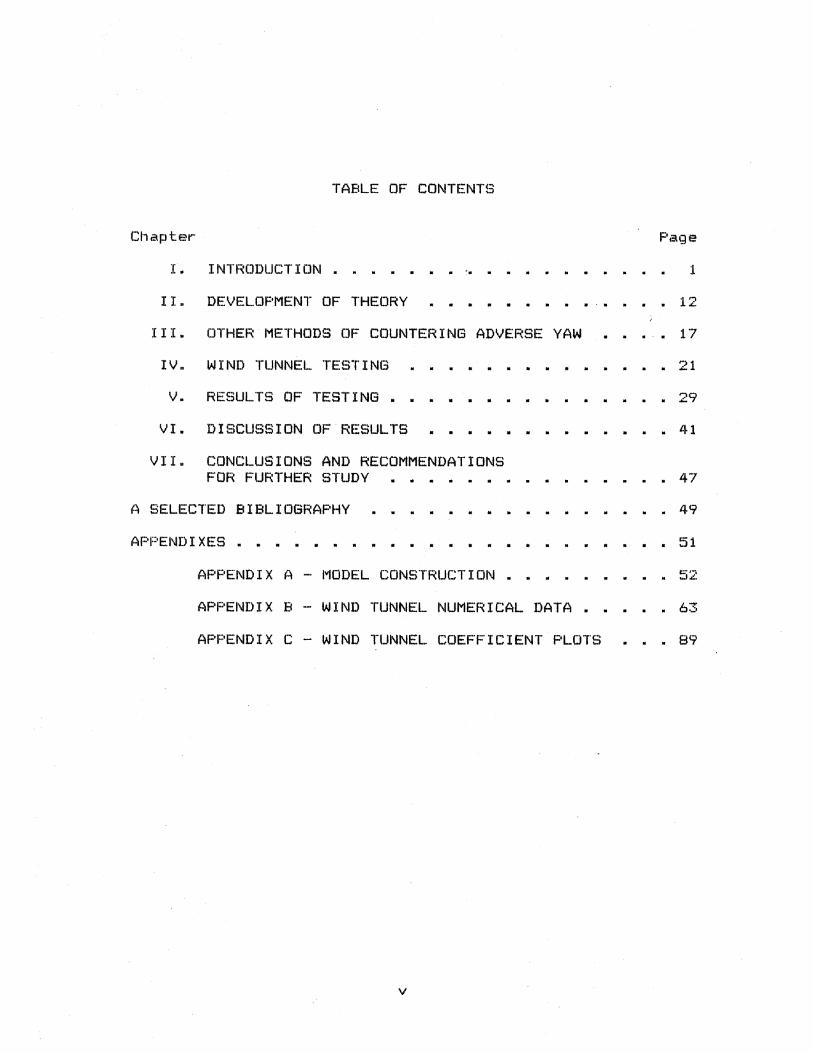
TABLE OF CONTENTS
Chapter- F'iage
I. INTRODUCTION . . . .. . :L
II. DEVELOPMENT OF THEORY :L '? . "-
III. OTHER METHODS OF COUNTERING ADVERSE YAW • • 17
IV. WIND TUNNEL TESTING
v.
VI.
VI I.
RESULTS OF TESTING . • .
DISCUSSION OF RESULTS
CONCLUSIONS AND RECOMMENDATIONS FOR FURTHER STUDY • • •
A SELECTED BIBLIOGRAPHY
APPENDIXES
APPENDIX A - MODEL CONSTRUCTION
21
• 29
• .l~ 1
• • • 47
• 49
. . .. . 51
APPENDIX B - WIND TUNNEL NUMERICAL DATA ... 63
APPENDIX C - WIND TUNNEL COEFFICIENT PLOTS ... 89
v
LIST OF TABLES
Tiabl e Page
I. Wind Tunnel Testing Sequence . . . . . . " . .
vi
LIST OF FIGURES
Fi gur·e
1.
4.
5.
6.
7.
8.
9.
10.
11.
12.
14.
15.
Forces Acting on an Aircraft in Level Flight and in a Turn .••
Lift and Drag Forces on an Aircraft with Ailerons Displaced for a Turn to the Right •.•••
Drag of an Aircraft for Low Subsonic Velocities • • •
Aileron Profiles . . . . . . . . . Drag Cur·ves at -6 Degr·ees Angle of Attack
Drag Curves at -4 Degrees Angle of Attack
Drag Curves at 0 Degrees Angle of Attack
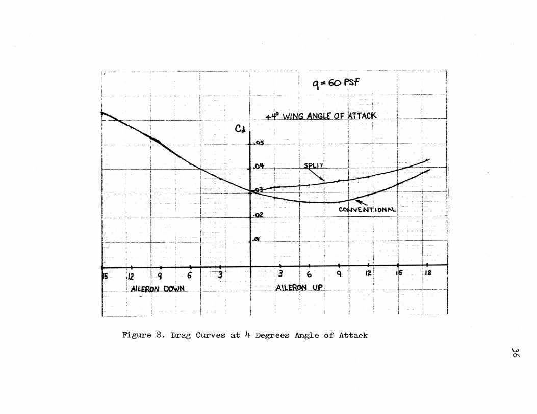
Dr·ag Curves at +4 Degrees Angle of Attack
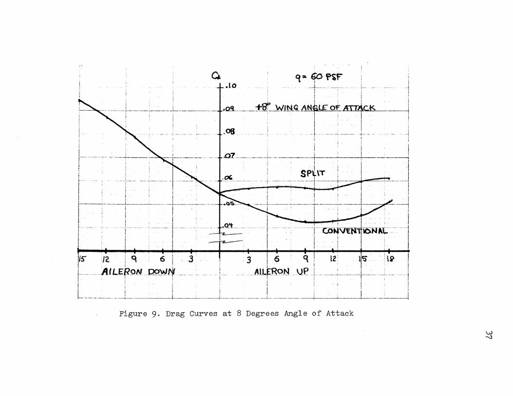
Drag Curves at +8 Degrees Angle of Attack
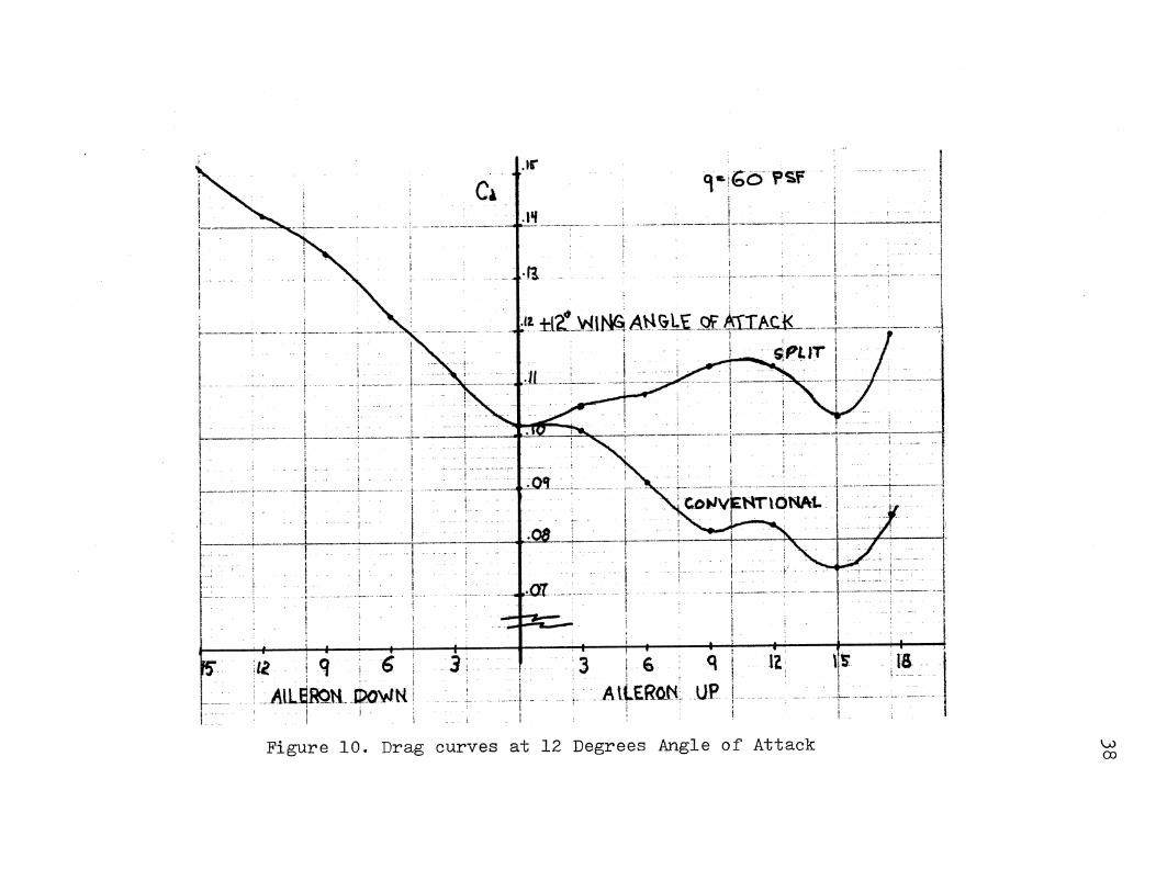
Drag Curves at +12 Degrees Angle of Attack
Ikag Curves at ·t-15 Degrees Angle of Attack
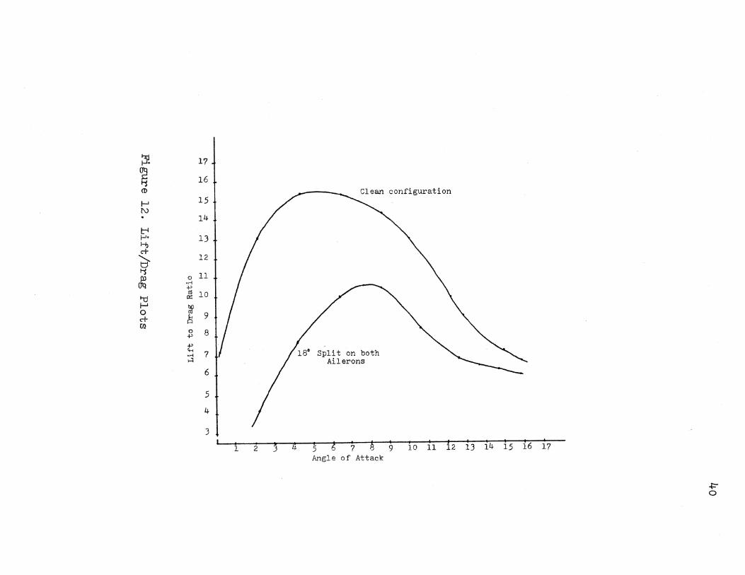
Lift/Dr·ag Plots •••
Rib Pr·ofiling Fb:ture • •
Rib Sections
Tunnel Mounting Fixture •
16. Milled Aileron Components ••.
17. Aileron Indexing Brackets . . . . 18. Rigging Structure •••• • •
19. Complete Structure Prior to Covering
20 .. Tail Sting Components ••• . . . . . .
vii
. .
.
. .
. .
. .
•
.
.
.
Page
c· ,.J
7
8
• 15
. . 3:~;
. . ~~4
. . 35
. . 36
. . 37
. . :~;8
. . ~59
• • • 40
. 55
. 55
. . . 57
. 57
. . • ~'59
.. . t39
. 60
• 60
Fiqure P1-aqe
21 ... ·rest Model Installed in Wind Tunnel with Ai 1 erc.1m; in Nt=Jutral Posi ti 1:1r1s . 6'2
2:;:~. Ma:·:imum Split of Ai lercms . . 6'"·' ..:..
:;:~::~. RLtn 1. Cl VS Alpha 89
24. Run 1. Cd vs Alpha . . 90
1""\t:. .. Run 1. Cm vs Alpha 91 ,£,, .. J. . . . . . 26. Run 1. Crm vs Alpha. . . . . 92
';.:!7. Run 2. Cl VS Alpha . . . . 93
28. Run 2. Cd vs Alpha. . . . . . 94
29. Run . ., Cm vs Alpha 95 ...... . . . . . . 3(). Run ··~ ..::.. Crm vs Alpha 96
31. Run 3 .. Cl vs Alpha . 97
~5~!. Run 3. Cd VS Alpha . . 9E3
:~;3. Run 3 .. Cm VS Alpha . . 9''Y
:34-. Run ::; It Crm VS Alpha . . . 100
....... Run 4 • Cl vs Alpha. 101 . .::.,J .. . 36. RLtn 4. Cd vs Alpha . . . 102
~$7. Run 4. Cm vs Alpha . to:~:
~$8. F~Ltn 4. Crm vs ?Upha 104
:~9. Run a::. .. Cl vs Alpha 105 '-~• . 40. Run C'
...J. Cd vs Alpha . . . 106
4l.. Run .:::· Cm vs Alpha 107 ....~. . 42. Run 5. Crm vs Alpha 108
4~$. Run 6. Cl vs Alpha. . 109
44. Run 6. Cd vs Alpha . 11 (l
4""' ...Jo Run 6. Cm vs Alpha. . . . 1 1 1
46. Run 6. Cr·m vs Alpha :l12
viii
Figure p,'::\qe
47. Hun 7. Cl vs Alpha . . . . . . . . . 11:3
48. F~un 7. Cd VS Alpha . . . . . . . 114
49. Run 7. Cm vs /Upha . . . . . . . . . . . . . 115
50. Run 7. Cr·m vs Alpha . . . . . . . . . . 116
51. Run 8. Cl vs Alpha . . . . . . . . . . . . . 117
5:2. Run 8. Cd VS Alpha . . . . . 118
5~5. Run 8. Cm VS Alpha . . . . . • . . . . . . . . . 119
54. Run 8. Crm VS Alpha . . . . . . . . . . . . . . 120
55. Run 9. Cl vs Alpha . . . . . . . . . . . 121
56. Run 9. Cd vs Alpha . . . . . . . . . . . 122
57. Run 9. Cm vs Alpha . . . . . . . 1 ::~~..)
58. Run 9. Crm vs Alpha . . . . . . . . . . . . 124
59. Run 10. Cl VS f'-ll. ph a . . . . 1 r"\1::: ..::.'-'
60. Run 10. Cd vs Alpha . . . . . . . . . . . . 126
61. Run 10. Cm vs Alpha . . . . . . 127
6''~ ..:: .. Run 10. Crm vs Alpha . . . . . . . . 128
6~:;. Run 11. Cl vs Alpha . . . . . . 129
64. Run 11. Cd VS Alpha . . . . . . . . 1:::;o
6""" J. Run 11. Cm VS Alpha . . . . . . . . 131
66. Run 11. Crm vs Alpha . . . . . . . . 132
67. Run 12. Cl vs Alpha . . . . . . 133
68. Run 12. Cd vs Alpha . . . . . . . . . . . . 134
6CJ • R1 . .1n 1:2. Cm vs {Upha . . . . . . . . . . . . 135
70. R1..m 1'"·' ...... Crm vs Alpha. . . . . . . . . . . 136
71. Run 13. Cl VS Alpha . . . . . . . . . . 137
.. ,2. R1..1n 13 • C!::l vs Alpha. . • . . . . . . 1~.::;8
Fi gun? P;age
T~:. Run 13. Cm vs Alpha . . . . . . 1:39
74. F~un 1''~ ..:: ... Cr·ni vs Alpha . . . . . . . . . . . . :1. /.f.(l
7~i. Run 14. C:l vs Alpha . . . . . . . . . . . . . . 141
76. Run 14. Cd vs Alpha . . . . . . . . . . . . 142
'77. Rt.tn 14. Cm vs Alpha . . . . . . . . . . . . 143
7€-3. Run 14. Crm VS Alpha . . . . . . . . . . 144
79. Run 15. Cl vs Alpha . . . . . . . . . . 145
80. Run 15. Cd vs Alpha . . . . 146
81. Run 15. Cm vs Alpha • . . . . . . . • . . . . . 147
El2. Run 15. C:r·m vs Alpha . . . . . . . . 148
8 .... .,.::. Ill Run 16. Cl vs Alpha . . . . . . . • . . . . . . 149
84. Run 16. Cd vs Alpha . . . . . . . . . . . . 150
8""' ;.J. Run 16. Cm vs Alpha . . . . . . . . 151
86. Run 16. Crm VS Alpha . . . . . . . . . . 152
87. Run 17. Cl vs Alpha . . . . . . . . 1 0::'':!' ;;J~·
88. Run 17. Cd vs Alpha . . . . . . . . . . . . 154
89. Run 17. Cm vs Alpha . 0 . . . . . . . . . . 155
90. Run 17. Crm vs Alpha . . . . . . . . . . . . 156
91. Run 1.8. Cl vs Alpha . . . . . . . . . . . . 157
9~:.• ~ .. Run 18. Cd vs fUpha . . . . . . 158
(t~: .. RLln 18o Cm vs Alpha . . . . . . . . . . 159
94. 1::;:un 1EL Cnn VS Alpha . . . . . . . . . . . . 160
9C:' ,:J • Run 19. Cl VS Alpha . . . 0 . . . . . . . . 161
96. F~un 19. Cd vs Alpha . . . . . . . 0 . . . . 1.62
97. Rt..m 19. Cm vs Alpha . . . . 0 . . . . . . . 163
98. Run 1 (~ 0 Crm vs Alpha . • . . . . • . 164
Figure
99. Run 2Cl.
100. Run 2().
101. Run 20.
102. F~un 20.
Cl vs Alpha
Cd vs iUpha
Cm vs Alpha
Crm vs Alpha
. .
.
. . . . . . . . .
. . . . . . .
Page
165
166
167
• • • 168
NOMENCLATURE
Alpha. Angle of attack
AR Aspect ratio
b Wing span
Cd Coefficient of drag
Cd. C1::>eff i c i f:H1t of induced drag
Cd Coefficient of par·asi te drag
Cl Coefficient of lift
Cm Coefficient of moment
D drag
e Oswald wing efficiency factor
f Equivalent parasite area
L Lift
L/D Lift to drag ratio
q Dynamic: pressure
S Reference area
V Airspeed
W Weight
_,P Air densi"t:y
CHAPTEF~ I
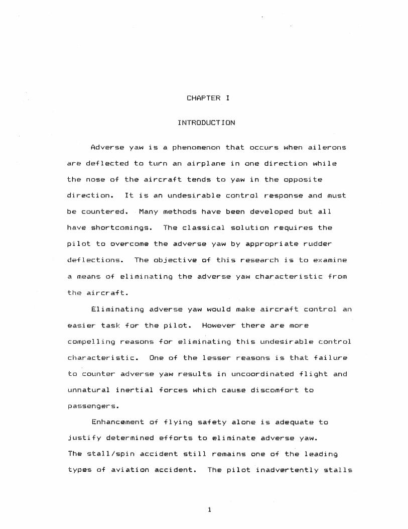
INTRODUCTION
Adverse yaw is a phenomenon that occurs when ailerons
are deflected to turn an airplane in one direction while
the nose of the aircraft tends to yaw in the opposite
It is an undesirable control response and must
be countered. Many methods have been developed but all
have shortcomings. The classical solution requires the
pilot to overcome the adverse yaw by appropriate rudder
deflections. The objective of this research is to examine
a means of eliminating the adverse yaw characteristic from
Eliminating adverse yaw would make aircraft control an
easier task for the pilot. However there are more
compelling reasons for eliminating this undesirable control
char ;;act er· i s t i c. One of the lesser reasons is that failure
to counter adverse yaw results in uncoordinated flight and
unnatural inertial forces which cause discomfort to
Enhancement of flying safety alone l. "" • :::> adequii~te tc:>
justify determined efforts to eliminate adverse yaw.
The stall/spin accident still remains one of the leading
types of aviation accident. The pilot inadvertently stalls
1
2
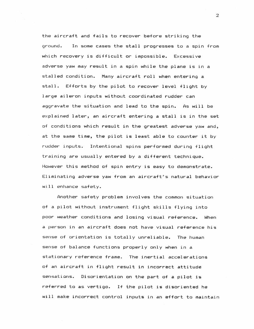
the aircraft and fails to recover before striking the
ground. In some cases the stall progresses to a spin from
which recovery is difficult or impossible. Excessive
adverse yaw may result in a spin while the plane is in a
stalled condition. Many aircraft roll when entering a
stall. Efforts by the pilot to recover level flight by
large aileron inputs without coordinated rudder can
aggravate the situation and lead to the spin. As will be
explained later, an aircraft entering a stall is in the set
of conditions which result in the greatest adverse yaw and,
at the same time, the pilot is least able to counter it by
rudder inputs. Intentional spins performed during flight
training are usually entered by a different technique.
However this method of spin entry is easy to demonstrate.
Eliminating adverse yaw from an aircraft•s natural behavior
will enhance safety.
Another safety problem involves the common situation
of a pilot without instrument flight skills flying into
poor weather conditions and losing visual reference. When
a person in an aircraft does not have visual reference his
sense of orientation is totally unreliable. The human
sense of balance functions properly only when in a
stationary reference frame. The inertial accelerations
of an aircraft in flight result in incorrect attitude
sensations. Disorientation on the part of a pilot is
referred to as vertigo. If ihe pilot is disoriented he
will make incorrect control inputs in an effort to maintain
-~· ·-·
level flight. If the pilot is not trained for instrument
flight~ he may easily panic and make incorrect decisions.
The typical accident sequence is one in which the
noninstrument pilot inadvertently gets caught in bad
weather, becomes disoriented, loses control of the
aircraft, and crashes. Such accidents are usually fatal.
Uncoordinated flight resulting from adverse yaw is a prime
contributor to vertigo. Th~ pilot would have a much better
chance of maintaining level flight after losing visual
reference if his aircraft was incapable of producing
The elimination of adverse yaw would therefore be
desirable from a safety standpoint. A stall proc:Jf
aircraft without adverse yaw would be a major improvement
ever most current general aviation aircraft.
Before being able to counter adverse yaw it is
necessary to understand the mechanism that causes it.
Quantitative analysis requires the use of rather complex
·f 1 ui d t.he!Clr" i es. Qualitative study of the mechanism of
adverse yaw can be accomplished by a much more straight
forward process using physical laws.
An aircraft is supported in level flight by
symmetrical distribution of lift en the wings. It i !S
necessary to bank the aircraft to effect a coordinated
"l:l .. II'"Tl • <Coordinated flight is flight in which all inertial
accelerations are perpendicular to the floor of the
iain::r·<aft.) The bank tilts the lift vector in the desired
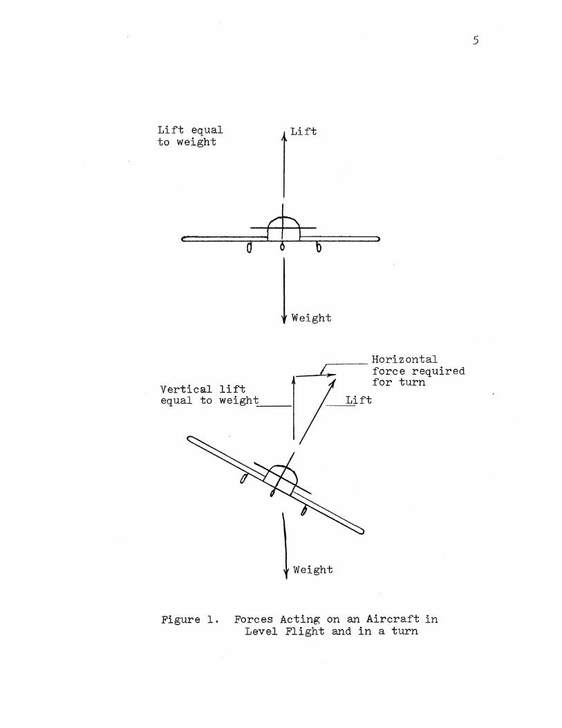
direction of turn. The corresponding horizontal component
of the lift force provides the horizontal acceleration
necessary to accomplish the turn. This is illustrated in
Figure 1. Some means are necessary to cause the aircraft
to roll about the lateral axis. This is done by altering
the lift distribution of the wing to a nonsymmetrical
state. This creates unbalanced moments about the
longitudinal axis and the aircraft rotates about that axis
until symmetry is restored. The Wright brothers initially
4
accomplished this by twisting the wings in flight. Warping
the wing structure had many disadvantages. The primary
disadvantage was the difficulty of building adequate
flexibility for in flight wing warping and at the same time
obtaining adequate structural strength and resistance to
warping under load. At the higher speeds at which aircraft
now operate, wing flutter would be a serious problem.
Moveable surfaces <ailerons) were developed to alter the
lifting characteristics of the wing. The movement of the
ailerons is a differential type of motion to increase lift
on one wing while decreasing lift on the other. The
ailerons are displaced in opposite directions from their
neutral position.
An aircraft in flight experiences drag forces
resulting from its movement through the atmosphere. For
steady flight to be maintained the drag forces must be
maintained in a state of symmetry. Unfortunately, when
symmetrical lift is disturbed to roll the aircraft the
Lift equal to weight
...
Vertical lift
0
Lift
b
Weight
..--- Horizontal force required for turn
equal to weight:;__ __ Lift ---=-=
Weight
Figure 1. Forces Acting on an Aircraft in Level Flight and in a turn
5
6
symmetrical drag is also disturbed opposite to the desired
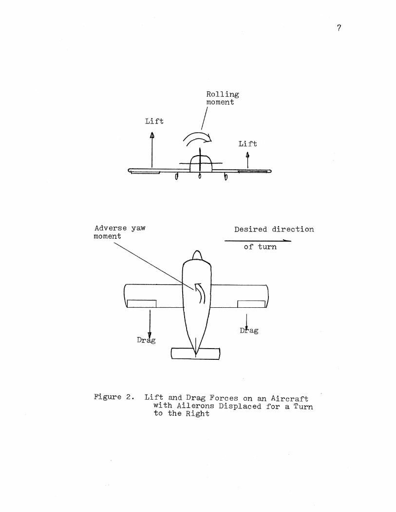
direction of turn. This is the mechanism of adverse yaw.
Figure 2 illustrates the lift and drag forces for an
aircraft with the controls displaced to cause a roll to the
right. Maintaining drag symmetry during a roll would
eliminate adverse yaw.
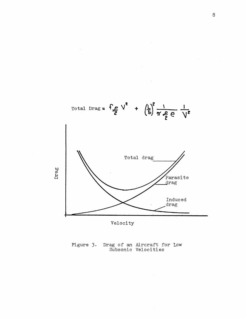
Drag experienced by an aircraft is categorized into
parasite drag and induced drag. Parasite drag is the drag
that results from resistance to motion through the
atmosphere and increases with increasing speed. Induced
drag is drag caused by the production of lift. Induced
drag is high at low speed and low at high speed. It is not
intuitively obvious that induced drag should be inversely
proportional to velocity. Further explanation of the
functional relationship of drag and velocity is provided in
chapter two. Figure 3 illustrates the parasite~ induced~
and total drag of an aircraft as a function of velocity.
Since induced drag plays a key role in the mechanism of
adverse yaw it can be seen that adverse yaw will be more
pronounced under conditions of high lift and slow speed~
the conditions that create high induced drag. This is why
an aircraft approaching a stall is in a condition where
adverse yaw forces are high. Since dynamic pressures are
low at the low speed associated with the stall the aircraft
control surfaces have the least capability to counter
adverse yaw when the adverse yaw forces are greatest.
Induced drag is a function of lift on the wing.
Lift
c,
Adverse yaw moment
i d
Rolling moment
I 0 Lift
$ t b
Desired direction
of turn
Figure 2. Lift and Drag Forces on an Aircraft with Ailerons Displaced for a Turn to the Right
7
Total Drag:: I -+ \Jt
Total drag ___ ____,
Velocity
Induced drag
Figure J. Drag of an Aircraft for Low Subsonic Velocities
8
9
Therefore any change in lift will result in a change in the
induced drag of the wing. The differential aileron action
effects the roll necessary for a turn by modifying the lift
distribution of the wing and the drag distribution is
altered as a consequence. Unfortunately the drag
distribution is altered in such a fashion that it is not
symmetrical and the aircraft tends to yaw. If the ~aw were
in the desired direction of turn it would give a favorable
yaw roll coupling. Unfortunately it is in the opposite
direction and opposes the turn. This is the situation
illustrated in Figure 2. In some situations it can be the
dominant factor and result in the aircraft turning in the
opposite direction. Ultralight aircraft sometimes
experience this condition and they must be turned by the
use of wingtip drag devices instead of ailerons. The
man powered aircraft recently developed by Paul McCready
experienced this difficulty (6). Being able to turn was
one of the greatest challenges to the development of the
man powered aircraft. The early experimental aircraft
built by the Wright brothers also proved difficult to turn
because of the effects of adverse yaw. The problem was so
great that the aircraft would turn in the direction
opposite of the attempted turn du• to an unfavorable
yaw-roll coupling. It is a mark of their insight and
genius that they were able to identify the cause of the
problem and provide a solution <4>.
Aircraft of the size generally used by individuals for
10
private flying are not dominated by adverse yaw and can
provide satisfactory control by the use of ailerons.
However the adverse yaw is still present and a significant
consideration for aircraft flown by novice pilots.
Adverse yaw is not considered a problem for large
aircraft, such as those used for commercial operations.
Large aircraft generally fly at higher speeds where the
higher dynamic pressures on the stabilizing surfaces give
mere resistance to yaw. These aircraft are typically flown
by highly experienced and well trained pilots who are not
likely to have difficulty controlling the aircraft when
adverse yaw forces exist. Large aircraft have autopilots
and control augmentation systems capable of overcoming
undesirable control characteristics. However, designers of
commercial aircraft built for V/STOL operations must still
be concerned about the problems of adverse yaw.
The result is that efforts to eliminate adverse yaw
from an aircraft,s control response are directed at lower
speed aircraft piloted by less skilled pilots, i.e., light
general aviation aircraft. The economics of these aircraft
preclude the use of automated control augmentation systems
such as usmd on large aircraft.
An effective and economical method of eliminating
adverse yaw will improve the safety of light aircraft being
operated by novica pilots. The design developed in this

1 1
research is intended to meet this objective. As will be
explained in the following chapters, this design shows the
potential to meet the objective of improving flight safety
through improved aircraft control.
CHAPTEI:~ I I
DEVELOPMENT OF THEORY
Classical aerodynamic analysis methods employ
the use of coefficients for force measurement. The
coefficient is a nondimensional number chosen to fit the
following equation:
F ::::: C q S
F is the force being measured.
C is the coefficient for the force.
q is the dynamic pressure of the airstream.
S is a reference area.
The.type of aircraft considered for this design proposal
fly at low subsonic speeds where compressibility is not a
·factor. For incompressible flow dynamic pressure can be a
c.::d. cul.c::~ted by q == .f V /2 when~ f is the air· density and V
is the speed of the undisturbed airstream relative to the
For drag measurements the equation ~ecomes
Dr·.-ag ::::: Cd q S
where Cd is the coefficient of drag. For lift measurements
the equation becomes
Lift :::: Cl q S
where Cl is the coefficient of lift.
1 ') -
A similar system can be used fer moments by the addition of
a length term to the equation.
Moment = Cm q S 1
where Cm is the coefficient of moment and 1 is a reference
1 f:i!ngth"
Drag is usually analyzed iR two categories. Induced
drag is the drag resulting from the production of lift.
Parasite drag includes all other sources of drag.
Parasite drag is proportional to the square of
velocity and can be expressed as
Parasite Drag = Cdr q S
where Cdf is the coefficient of parasite drag.
desirable to express induced drag in the same way.
Induced Dra~J •= Ccij q S
where C~ is the coefficient of induced drag.
Whereas Cc~remains essentially constant for different
angles of attack~ C~ is totally a function of angle
As indicated in an earlier discussion induced
drag is inversely proportional to velocity. Cd; is f.~
function of angle of attack and angle of attack for an
aircraft in flight is related inversely to the velocity.
Classical aerodynamic theory shows that
Cda = Cl1 I 'tr' AR e
where AR is the wing aspect ratio and e is as an efficiency
factor to relate lift distribution to the
ideal elliptic lift distribution. ·rhen:.~f c:we cis;; Cl
increases the induced drag coefficient increases
14
f?.:·: ponent i ;ally. Since the function of an aileron is
to change the Cl of the wing actuation of the aileron will
change the induced drag of the wing. This will have the
greatest effect when Cl is high, or in other words at high
angle of attack or low speed~.
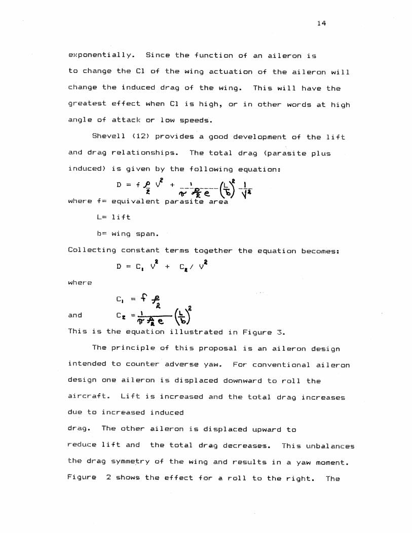
Shevell <12> provides a good development of the lift
and drag relationships. The total drag <parasite plus
i nduc:f:~d) is given by the following equation:
D - f.R_ v~ + ~··~-e.-···(\;) I ~ -~~·
when:? ·f:::: eqL.ti valent parasite area
L== lift
IJ::!! wing span.
Collecting constant terms together the equation becomes:
o == c, v2 + c. ; va
<an cl
This is the equation illustrated in Figure 3.
The principle of this proposal is an aileron design
intended to counter adverse yaw. For conventional aileron
design one aileron is displaced downward to roll the
Lift is increased and the total drag increases
due to increased induced
The other aileron is displaced upward to
reduce lift and the total drag decreases. Th:L s unbalances
the drag symmetry of the wing and results in a yaw moment.
Figure 2 shows the effect for a roll to the right. The
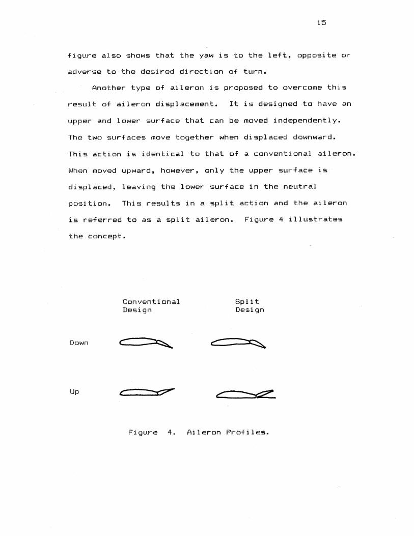
figure also shows that the yaw is to the left, opposite or
adverse to the desired direction of turn.
Another type of aileron is proposed to overcome this
result of aileron displacement. It is designed to have an
upper and lower surface that can be moved independently.
The two 5urfaces move together when displaced downward.
This action is identical to that of a conventional aileron.
When moved upward, however, only the upper surface is
displaced, leaving the lower surface in the neutral
position. This results in a split action and the aileron
is referred to as a split aileron. Figure 4 illustrates
tht:~ conc:E.'~pt.
Up
Cc)nvf:?nt i onal Df?!;i gn
c--·-~
c
Figur··e 4.
Split Design
.... c: ___ ~
c
Aileron Profiles.
16
The split aileron is used on the wing on which
the aileron is displaced upward. The deflection of
the split aileron increases the parasite drag to balance
the loss of induced drag and the increase of drag on the
opposite wing. Since induced drag decreases as the square
of velocity and parasite drag increases as the square of
velocity it is expected that the design must be optimized
for a specific velocity. This situation is typical of
design activity. Wind tunnel testing of this design has
shown that this split aileron design can actually be
optimized over a much broader range than might be expected.
This is explained in Chapter Six.
CHAPTER III
OTHER METHODS OF COUNTERING ADVERSE YAW
Numerous ether methods have been used in the past to
deal with adverse yaw. The purpose here is to review other
methods and point out their deficiencies, thereby
substantiating the need for an improved design.
The most common method has been to train the pilot to
input appropriate rudder displacements at the same time
ailerons are displaced. This can work fairly well if the
pilot is sufficiently skilled. It has the obvious
disadvantage of increasing pilot workload. It does not
work if the pilot fails to make appropriate inputs. A
pilot with low experience cannot be depended upon at times
of high stress to make all appropriate inputs consistently.
It was pointed out in the introduction that a pilot who is
spatially disoriented is at high risk. Another
disadvantage is that some situations require the pilot to
use the rudder for other purposes. The inputs to counter
adverse yaw must be superimposed on the inputs required.
Some aircraft have been designed with the aileron and
rudder controls interconnected in such a way that they move
at the same time to counter adverse yaw. The pilot
displaces the ailerons to affect a turn and the rudder
17
18
moves automatically with the ailerons. While this method
has some distinct advantages it has been poorly received by
pilots. Pilots have been unwilling to give up control of
the rudder because they cannot use it for other purposes.
This design can only be optimized for a narrow range of
speed. The aircraft will be operating off design at any
<:Jther speed. Interconnecting rudder and ailerons
eliminates the capability of making crosswind landings by
conventional methods.
Wing spoilers have been used with some success for
roll control. Ailerons may not be installed on the
aircraft. An upper surface spoiler is displaced to effect
a roll by reducing lift on that wing, causing it to sink.
The spoiler also increases drag on that wing. One
disadvantage is that it alters lift on one wing instead of
both. Another problem is that overall wing lift of the
aircraft is reduced during the roll since there is no
increase of lift on the other wing. The most serious
problem with using spoilers is the highly nonlinear control
characteristics of spoilers. Without automatic control
augmentation systems it is difficult to obtain acceptable
flying qualities using spoilers. For small displacements
the spiJiler gives little control response, but the response
can become very pronounced at higher spoiler angles. This
would give the pilot a "stuck drawE-!r" effect.
One very interesting design can be found on the Helio
aircraft. This aircraft is designed for short field
19
operation and operates under the conditions which give the
greatest adverse yaw forces. The wing has flaps and
leading edge slats which enable it to fly at high Cl or low
airspeeas. The wings have a large span and the ailerons
are on the outer portions of the wing to permit essentially
full span flaps. The yaw forces have a large moment arm to
create yaw moments. The fact that adverse yaw is a problem
on this aircraft is evidenced by the manufacturer adding a
device to counter it. A spoiler type device is deflected
on the upper surface in front of the aileron. This system
may even increase roll rate with positive G loading. This
solution would require structural design to carry the loads
across the cutouts for the spoilers. Since most aircraft
use stressed wing skins for structural integrity these
slots would weaken the wing. It would be difficult to
retrofit existing aircraft since a major wing redesign
would be required. If adequate drag is provided at low
speed it would predictably be excessive at high speed.
This system will not work under negative G loading. The
extra mechanical complexity might also be viewed as a
drawback.
Another method is the use of differential displacement
of the ailerons. The aileron displaced up is displaced
more than the aileron displaced down. This is usually
referred to as differential aileron action. The extra
displacement of the upward aileron is intended to suffer
parasite drag due to the departure from the basic airfoil
shape. This method has proved to be ineffective.
Another method of dealing with adverse yaw is with
automated control systems or yaw dampener systems. The
cost~ weight, and complexity of such systems preclude use
en small aircraft where they would be needed most.
20
CHAPTER IV
WIND TUNNEL TESTING
It was desirable to conduct wind tunnel tests to
carefully measure the split aileron performance compared tc
conventional aileron performance. Since the aileron
functions by modifying the wing airfoil it would at first
seem appropriate to use two dimensional airfoil testing
techniques. Airfoil data is usually determined by two
dimensional testing techniques to eliminate wing tip
effects. The test wing completely spans the space between
two parallel walls oriented perpendicular to the span.
Lift and drag values are determined with pitot static probe
measurements and application of momentum theory. Rae and
Pope <10) point out that this method is invalid far any
flow with separation. An aileron operates in the area of
the wing where same separation exists and the split aileron
concept is intended to cause additional separation.
Therefore two dimensional testing will not provide proper
data.
Direct force measurement in two dimensional testing is
difficult because the wing must touch the end plate walls.
Even very small gaps at the wing tips cause large
measurement errors (10). It is difficult to separate
21
forces acting on the wing from forces acting on the end
plates.
Two dimensional testing of this concept is not
desirable in any case. The reason for the difference
between two dimensional and three dimensional airfoil
performance is the alteration of flow characteristics
caused by the wingtips. The flow in the region of the
22
wingtips is drastically different from two dimensional
behavior and this is the very region in which the ailerons
operate. Additionally each aileron has two wingtips of its
own. Therefore meaningful testing must be done in a three
dimensional mode with proportions similar to the type of
aircraft intended to incorporate this concept.
Lift and drag performance is also sensitive to
Reynolds number CRN). Previous wind tunnel experience has
shewn that results obtained at RN of one million are valid
up to about twenty five million (10>. Since the aircraft
of interest for this design operate at Reynolds numbers
between two and seven million, it is important that the
testing be accomplished at RN of one million or higher.
This rules out the use of small slow speed wind tunnels.
Fer this test the Walter H. Beech Memorial Wind Tunnel
at Wichita State University was chosen. This tunnel has a
7 X 10 foot test section and can operate at Reynolds number
in excess of one million at the test section. This tunnel
is highly automated and computerized to provide corrections
for wind tunnel errors, i.e., blockage, buoyancy, etc. The
data produced by this tunnel of the highest quality and
well suited to the requirements of this test. A complete
description of the test facility can be found in reference
two.
A model simulating a small general aviation aircraft
was constructed to obtain realistic results. A NACA 23015
airfoil section was chosen for the model. Although the
actual airfoil section selected is not relevant to the
purpose of the test, it is important that the airfoil
chosen have no unusual characteristics. This eliminates
the possibility of obtaining unusual test results due to
some unique feature of the airfoil. The NACA 23015 airfoil
is typical of that used on general aviation aircraft.
Although airflow over a fuselage is not normally
influenced by ailerons, a fuselage does cause interference
on the wing flow characteristics and separation at the
fuselage wing junction. Therefore the test model wing was
equipped with a fuselage to simulate the real world
environment. An empennage was not used because it has no
bearing on wing performance and is difficult to simulate
realistically in the wind tunnel. Since the tunnel walls
alter the downwash behind the wing, the tunnel environment
is not the same as the free stream flow case unless the
model is small for the test section. This in turn will
result in a low Reynolds number. Use of an empennage for
wing testing can therefore cause distortion of the results.
Since a wind tunnel is bounded flow there are many
24
limitations to the use of wind tunnel data. Wind tunnel
data must be corrected for many sources of error and these
sources must be minimized by careful model design and
testing procedure. Reference nine gives a good development
for low speed wind tunnel corrections. One of the
advantages of the Walter H. Beech memorial wind tunnel is
the capability to remove the errors and produce corrected
output for the experimenter. This data output is produced
on line by computer and the experimenter can observe
results as the test is in progress.
The experimenter provides the tunnel operator with a
list of correction parameters before the test is started.
These parameters are entered into the computer data
reduction program. The details of data reduction and error
removal can be found in references five and nine. The
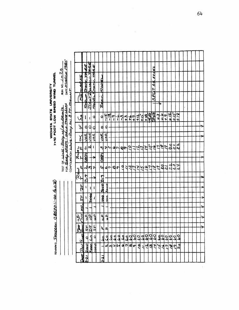
parameters calculated for this test are found on the first
page of Appendix B. The details of the test model
ccmstruction can be found in Appendix A.
Ideally the test sequence might be set up with the
wing at a certain angle of attack and then test data could
be taken for all possible control surface configurations.
Since this data is needed for many angle of attack settings
it would require that this sequence be repe~ted for each
angle of attack. Since the wind tunnel must be shut down
to change model configuration this would be very time
consuming.
The actual test was run by setting a specific control
25
surface configuration and than cycling the test model
through all angles of attack of interest. Since the angle
of attack could be altered by remote control with the
tunnel in operation this sequence resulted in considerable
time savings.
Since performance at a negative angle of attack is of
interest for a control surface some testing at negative
angle of attack is required. Also performance in the stall
mode must be tested to determine any unusual behavior that
may occur. A range of minus six degrees to stall
(approximately 18 degrees) was chosen for the test to meet
these objectives. The control surfaces were built for
deflections from fifteen degrees down to eighteen degrees
up in three degree increments. The upward deflection was
available in both normal and split mode.
Run 1 was made with the ailerons in normal position to
obtain basic model characteristics.
both ailerons down fifteen degrees.
Run 2 was made with
Subsequent runs were
made with the ailerons elevated at increments of three
degrees until full deflection of eighteen degrees was
obtained. Run 13 was made with the left aileron full down
and the right aileron full up. This measured the maximum
rolling moment capability in normal mode. On run 14 the
left aileron was remained down but the right aileron was
now split to full open position. This measured maximum
rolling moment capability in split mode operation. Runs 15
through 20 were then made with increments of aplit opening
on both from three degrees to eighteen degrees. This
provided a data base for comparing conventional versus
split mode lift and drag characteristics. Table I shows
the testing sequence.
The test data output is in numerical and graphical
26
form. Appendix B contains the numerical output which shows
force and moment coefficients as a function of angle of
attack. Dynamic pressure, mach number, and effective
Reynolds number are listed for each run. Appendix C
contains computer generated plots for coefficients of lift,
drag, pitching moment, and rolling moment as a function of
angle of attack.
Although care was taken to set angles of attack to
consistent values, i.e., 2,4,6, etc., it can be seen in the
numerical output that the actual angles of attack vary from
one run to another. Angle of attack is one of the
parameters in wind tunnel testing that requires correction.
The values shown in the numerical output are corrected
values.
This creates a slight inconvenience in the use of
the data. Since the data points in the listings are not at
a consistent set of angles of attack interpolations must be
made. Linear interpolation is not suitable because the
plots show substantial curvature at places.
A computer program was written to interpolate using
the cubic spline technique of numerical methods. This is a
classical mathematical approach which gives good results
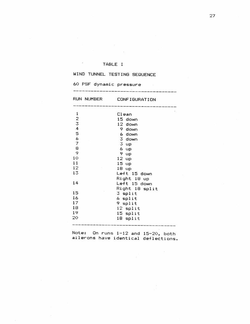
TABLE I
WIND TUNNEL TESTING SEQUENCE
60 PSF dynamic pressure
RUN NUMBER CONFIGURATION
1 Clean 2 15 down 'T ..... 12 down 4 9 down .:::· ...J 6 down 6 . .,..
·-' down 7 .. :!" ·-· up 8 6 up 9 9 up
10 12 up 11 15 up 1 ~,
"'- 18 up 13 Left 15 down
Right 18 up 14 Left 15 clown
Right 18 split 15 .. :r ·-· split 16 6 split 17 9 split 18 12 split 19 15 split 20 18 split
Note: On runs 1-12 and 15-20, both ailerons have identical deflections.
28
when the explicit functional form for a data set is not
known. The interpolation program was used to produce
coefficients for nonvarying angles of attack. Due to
length and complexity the computer routine is not published
with this thesis.
author.
It is, however, available from the
The interpolated data sets are used primarily for
making comparisons of multiple test runs. The graphical
plots are used for qualitative interpretations on specific
runs.
CHAPTER V
RESULTS OF TESTING
The wind tunnel tests produced some very useful data.
Examination of the graphical coefficient plots <found in
the appendices) shows the characteristics of the model and
analysis of the numerical data reveals the information
sought from the test.
Table I of chapter four shows the wind tunnel testing
sequence. Run number one is the basic model performance
with no control deflections. The Cl versus angle of attack
curve is typical for wing airfoils. The curve is
essentially linear until near the stall. A very slight
nonlinearity occurs around twelve degrees angle of attack.
The stall portion occurs over a fairly large range of angle
of attack. If this curve represented an actual aircraft it
would indicate excellent flying qualities because the stall
is gradual with sufficient warning to the pilot that the
stall is imminent.
The Cd versus angle of attack is typical with a
minimum drag at just under zero degrees angle of attack.
For the NACA 23015 airfoil used this is expected. A
noticeable discontinuity occurs at around twelve degrees
29
angle of attack and a small discontinuity in the stall
region.
30
The fuselage acts as a lifting body and contributes to
lift until it stalls. It is a streamline body with low
fineness ratio. One characteristic of such streamline
bodies is a positive pitching moment whereas the airfoil
has a very slight negative pitching moment. The pitching
moment curve shows that Cm is positive but takes a drop to
near zero at about twelve degrees angle of attack. This is
good evidence of a change of flow characteristics on the
lifting body. It is obvious that something is happening in
the region of twelve degrees angle of attack. Examination
of all of the plats shows that this occurred on all twenty
runs and at approximately the same angle of attack. The
curve discontinuity can be found on the plots far lift~
drag~ pitching moment~ and rolling moment. Very convincing
evidence can be found in the moment coefficient curves to
indicate that wing root separation is occurring here along
with separation on part of the fuselage body.
When the lifting body stalls it would be expected that
wing root separation would occur at the same time. This
would cause a slight change in wing lift and pitching
moment. The rolling moment changes at twelve degrees angle
of attack and the right wing root separation is greater
than the left wing root separation.
This accounts for a slight lass in the lift as the
angle of attack is increased through this region, for the
31
sudden increase in drag, and for moment curve fluctuations.
Since the expected results of wing root separation are
found in all of the curves, this is the likely explanation
for the behavior in the twelve degree angle of attack
region.
The cause of the fluctuation in the stall region can
be found in the rolling moment curves. It is impossible to
build an aircraft so that both wings stall precisely at the
same time. Rolling moments change significantly when a
nonsymmetrical stall occurs. The rolling moment curves
indicate this change. The first drop in the lift curve is
small and represents another indication that the stall
transition is gradual.
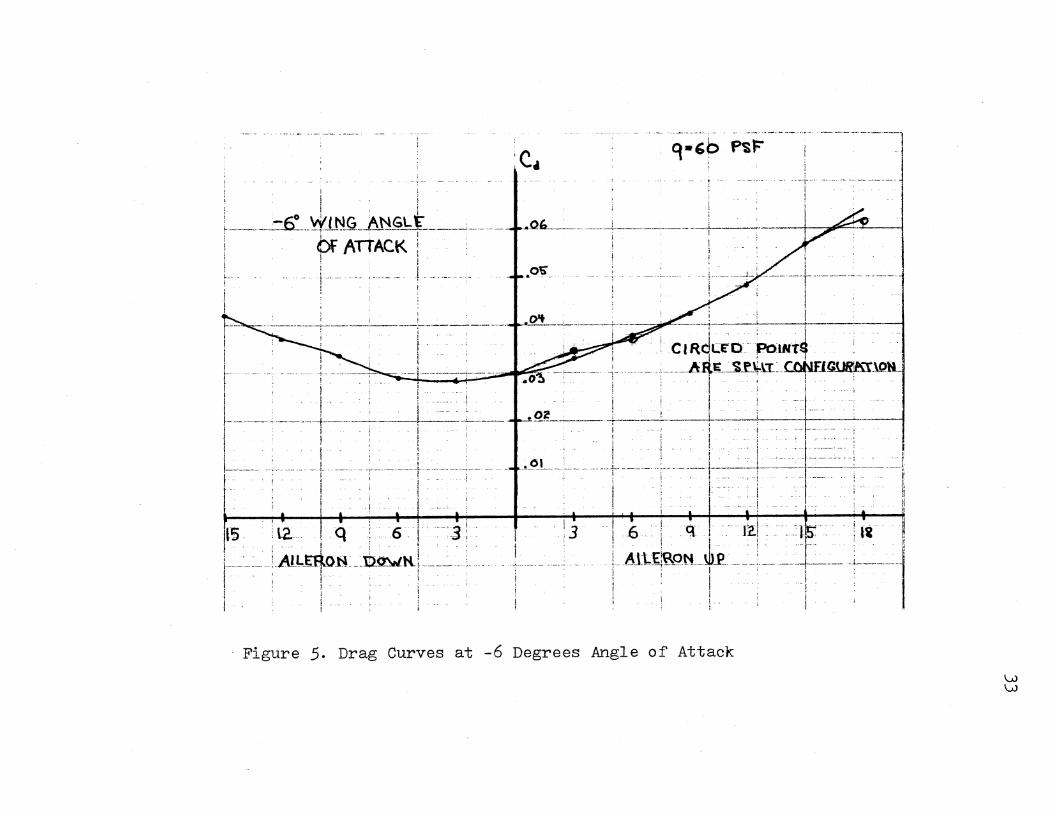
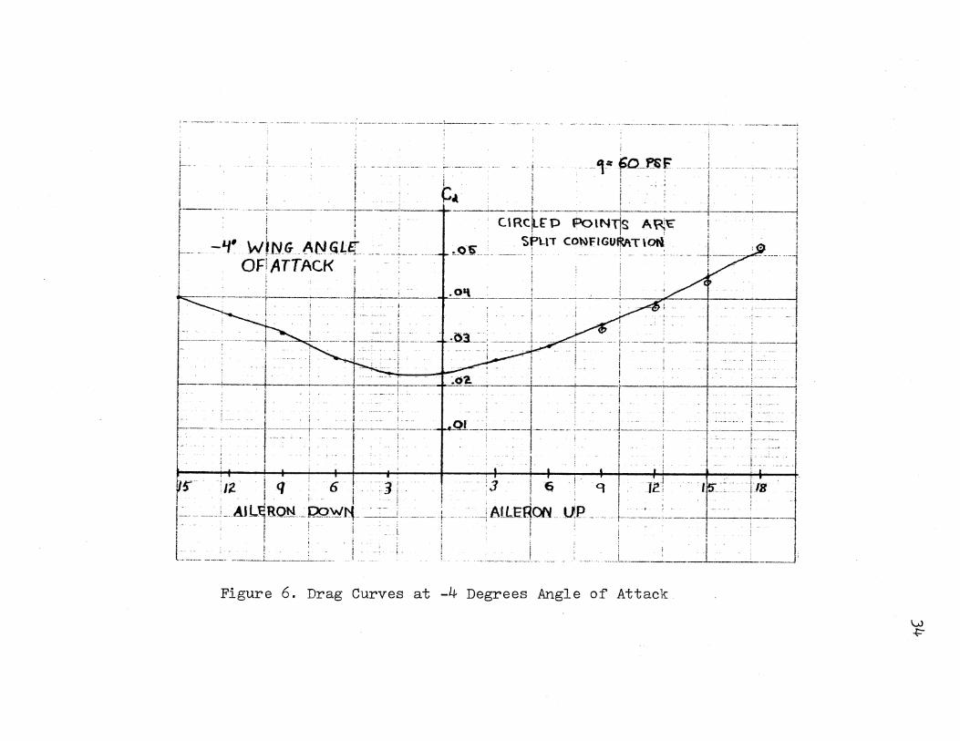
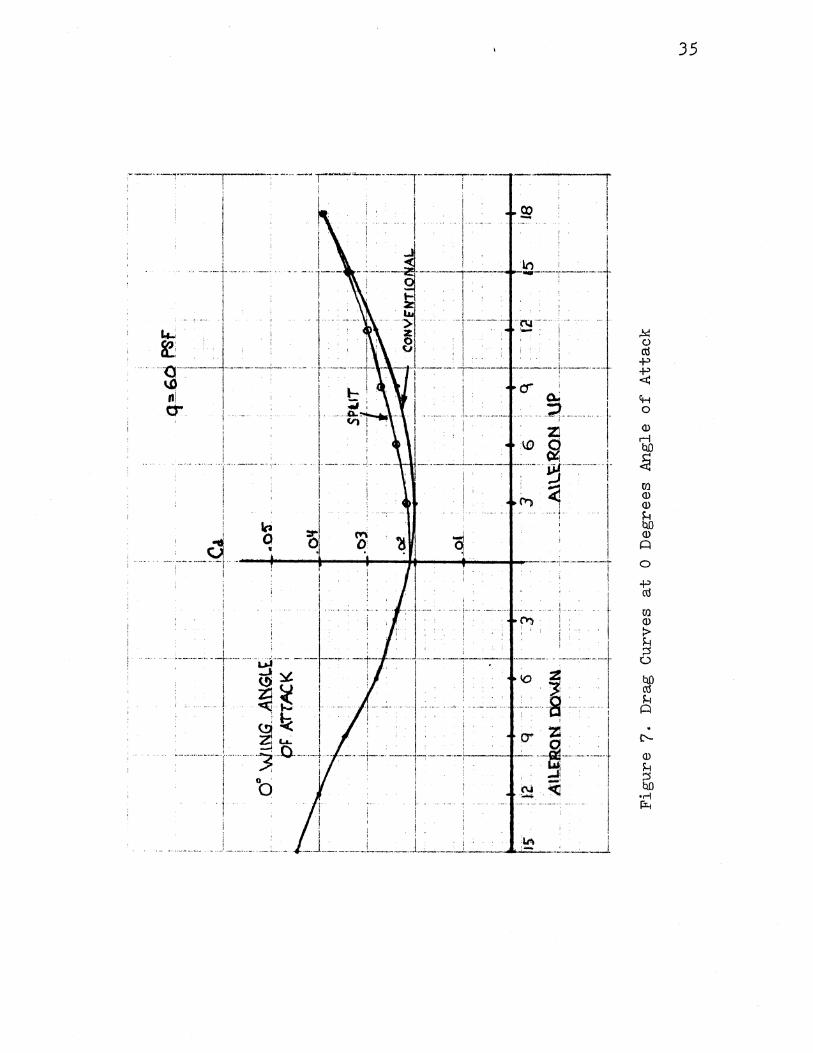
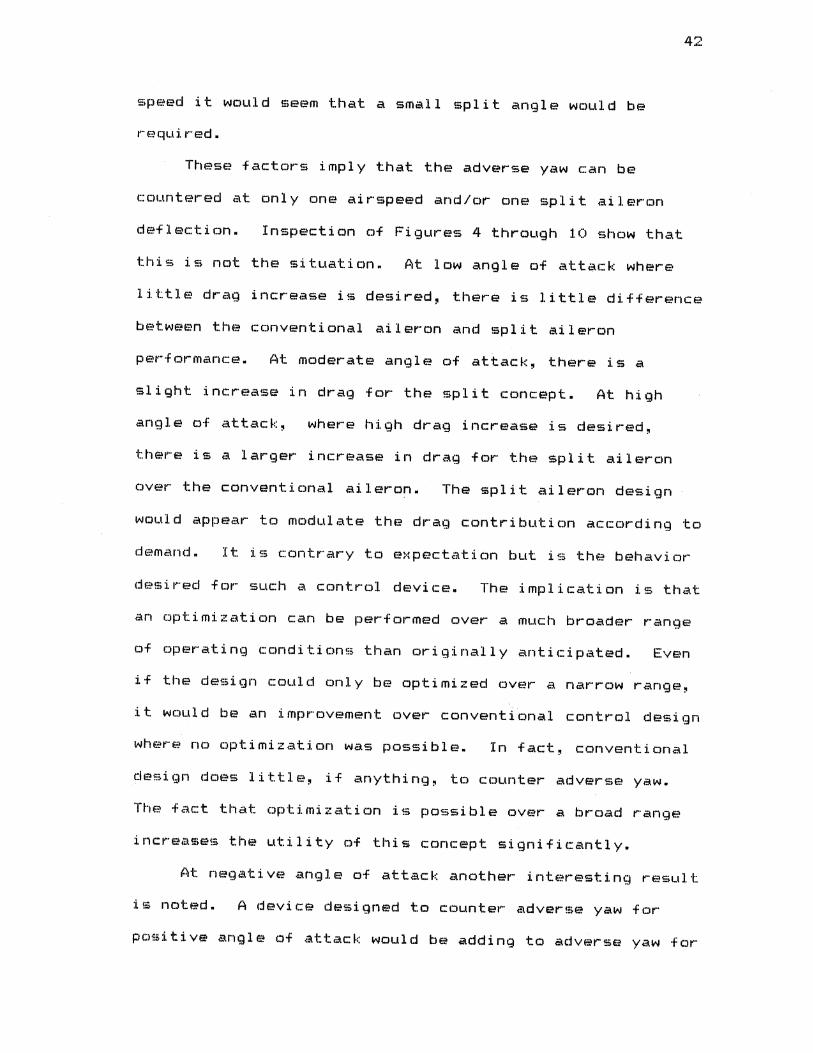
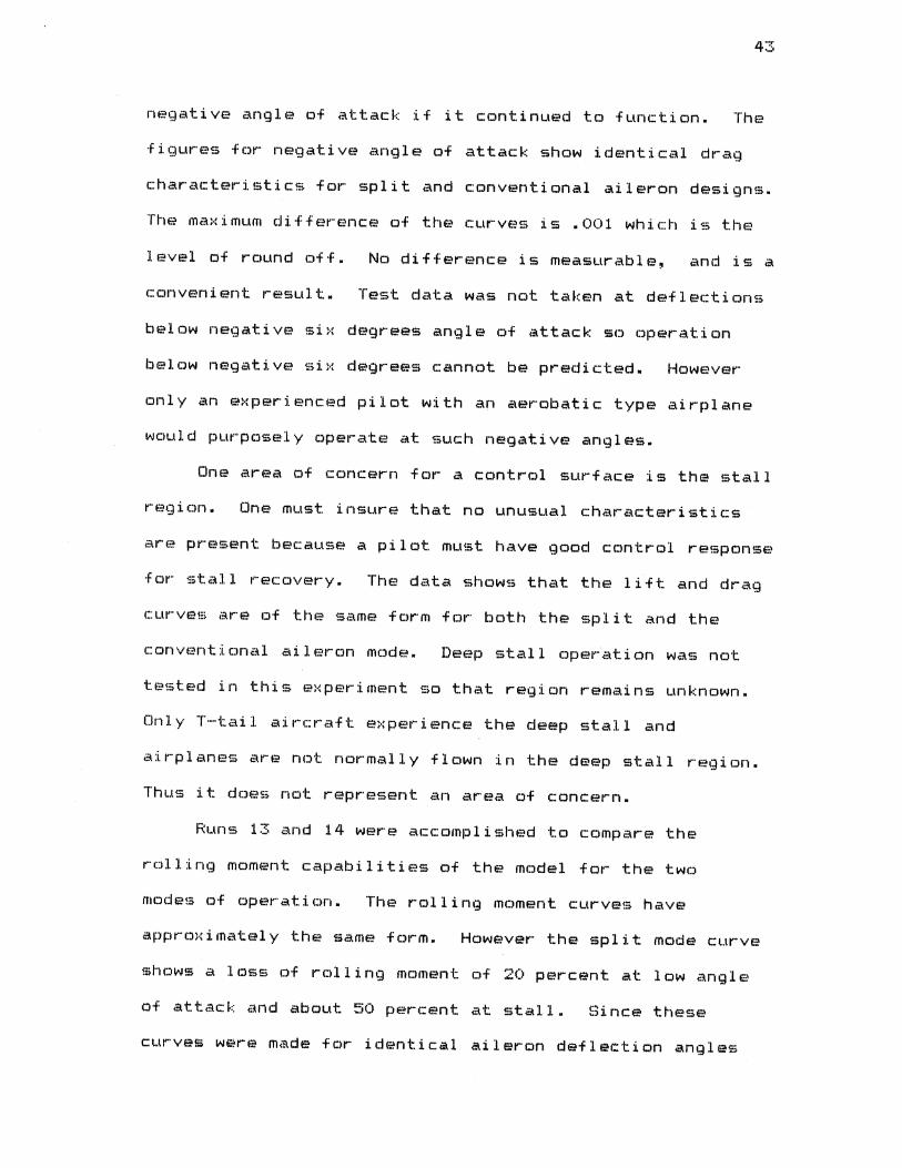
Plots of drag coefficient versus aileron deflection
were prepared for several wing angles of attack to examine
the results of the aileron performanc~ <Figures 4 through
10). These plots show the drag characteristics of the
split aileron along with the conventional aileron. At
small negative angles of attack there is no significant
difference. At small positive angles of attack there is a
small increase in drag with the split configuration. For
high angles of attack the drag increase is progressively
higher. Figure 9 shows some erratic behavior. This plot
is at twelve degrees angle of attack where drag
characteristics are changing due to lifting body and wing
root flow separation. A mutual interference is apparently
occurring where the upward aileron deflections are
influencing the fuselage and wing root separations.
Remnants of this behavior are still apparent at fifteen
degrees angle of attack <Figure 10).
32
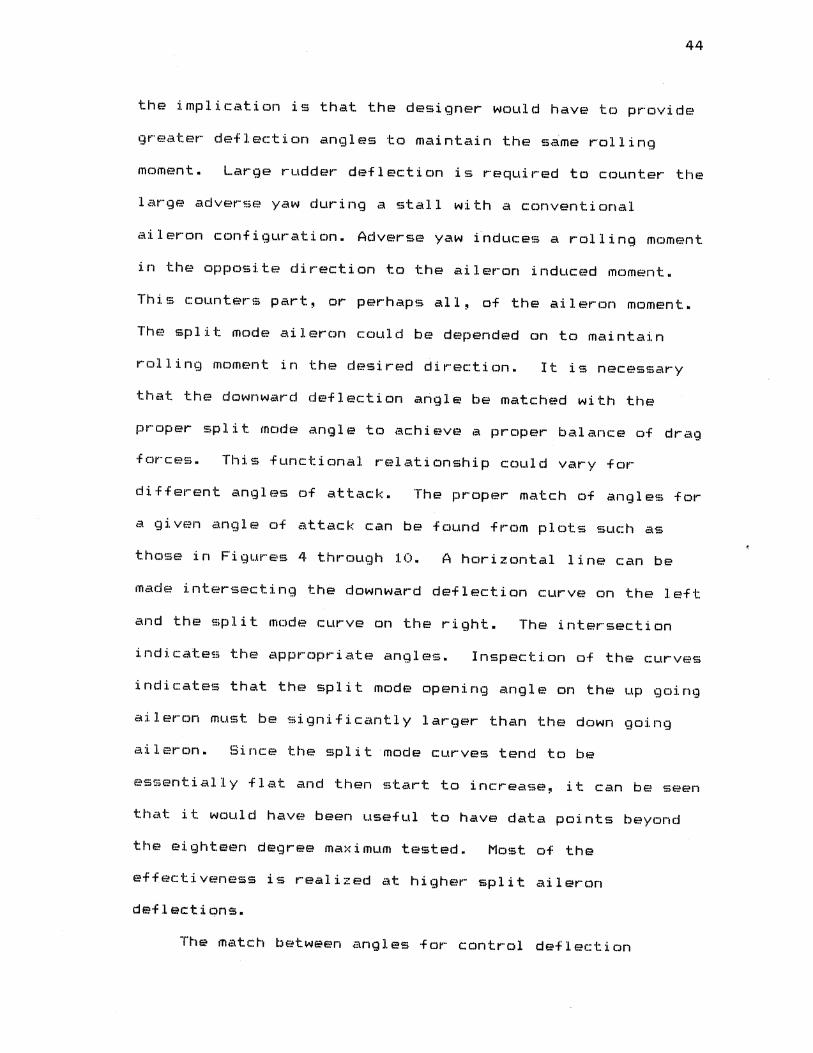
The lift to drag ratio <LID>, is a useful parameter
for indicating aircraft performance and is the glide ratio
of the aircraft. A high L/D implies an aerodynamically
clean aircraft capable of a long glide at a shallow angle
and low L/D implies a steep glide angle. Figure 11 was
prepared to show the affect of the split ailerons on the
L/D ratio for the model.
' ' ! ,_ i
' i : ! ' I
-~o WING ANGL£ ___ u_ ____ bF_P:nACK-;---------- ---
1 l
I --- -!
:c. q•E;b p~f:' -----------1
l
.of:L ________ __J_ _________ - -+---____:- 1 ;=; ---'-------;
.o-s- ----- ---~ ------- ----
1
I l
------------;----j ______ t__ ___________ .f. .O't --~--------'--c---~---1 - • ! - - - ; ClR~CE'O- PolNT4 -
I
r l j . ! ' i . : J l , ! I
1-------------~-~-----: ____ L.~---i I 1
l ' !
I I ! , I i I i !
1-------- -.. --!.- ----- ------+------------- ---I I
- - I ·q . 6- ____ 3i ~5 . \.2. i : - - :
. I ' ;r· ___ : _____ :.At~_Efto_N ___ '[j)_~N- _____ :__
. : ! ' ! '
I . i . : I ;
______ /t4-~~~Jf.:\.I .. ~1G1JR'I\\_\ON
I ---------- ___ J. __ -------
!
:3
;
q i -·---1 \.
_ L A1\..flR9t'L\b1! _______ _ i - I ! i , I I i
! t t-- - -: !_:-~--~-- -_~--~
1----- - : l!
li - h
~
--1
t
Figure 5. Drag Curves at -6 Degrees Angle of Attack
1...0 1...0
---------------------' ------- -----·-- -- - -·-- ------ -- ------------· . ------~ "l
i r--·--1 - : t·----------- --~------ . ' . I ' ' ... ,. 6D !'liE .
f'-------.--- ---+-- -- ~-~ f ···· : ~~ I · ~ I - ~, ~ 1 -- · 1
I j - ; --- ---+---- ! ' I l ~· . -'f W11\1G A!lllit~ . ' . CIRC~fp .,;iN~ AP;\o--_- ----r- ~ I OF: ATTACK i ~~ ..... .Ol\". ·- 'Of'LlT CONFIGU~Tlooi . i . i I i j . ~ ~+---- ' . ---------1
-r~~-L--~l·,_~O'\ . j ' I -------]-··----~---'- l
.:--:~~ I : 1 . :· - i , ~ r --~ ~=~ - ,_
l ' - - l
-- - - 1 ' . I .. . •. : I • -- - ----- ~--:--._ t -=---~-~-:.=:_.'_ =.:..___ ' . - . ~ .. - I -. - t·
! • . ; ; -r __ --~:=--,-- iz-:----
1iq--:- 6 -T- -~]; f - ~j i i -,- 9 l ,}!-! 1k:~: [Is
I - ; I - i : ! . I -1-- :
1 ~-------- _ AtL~RQ~ -~WI'(_~- ____ i ----- ._;AlLE~QN __ _up----- 1---· .:.~---t-~:____: _____ _ - - 1 ! i - ' ; I I i :-I I - I I I • -
t: __ ::_ .:. ___ ~_-__ :_~_.l_~: __ J :_ ~-- · :. i _ __ __________ __! _______ . _________ L , - i •---Figure 6. Drag Curves at -4 Degrees Angle of Attack
'vJ +=-
!
I l
.......... .j. -······ .......... .
l .( '
~ . ~' ' ! ~! . . •
..... '---~-------- ____________ _; ___ ..
111 1 tT !
I
i . J .. ------ ....
j
I
-'·-··------~ . I
Ira a •
35
:-; -··----------- --- ·--- ---- "1
! q•60PSF
i
!
1 -- -
' l
~ - I : - i --- - , - : l ______ _,_ ____________ _! ____ • _____ j__±~ Wtritt ANGLE_ OF ~TIACK ____ _l__ _j
. . l ! i i C• . ' ' t
' ' tl4 ' ' ' I ! j I i ! 1
! - ; --·----- -- - - -- ~05. -- ----- - f - --- - '- -- ~ -- ---- -~ ---- ---l- -- - - --- -1 l . ! ! ! ~,
I ' !
! . : 1 . ' ! 1-----------__l____ L-+--__ _;____SP!JL__ ___ ;__ -----1 • ! . • """'---: , I' I ; . ~ : .. - -~ I - - -- -
f · ·····~ ·· ·~·-··· ·- ~I~· ··· + .~.:... , . ; ... , . . . , ·- · r·-__ -·. ! --~1 f I --~- • ~ i I - ___ , _____ ;: • I
I .... .,.,__ . I • l
~ . / ! - --. j C~\IE.N't\ON.P..\.! i ji ~---------- l ; --.----;--,--- i ! j 1: !' ' ' I I I ' '
, 1 , r - -i 1·
1--~---- ·- -- _)~--- - --------L------; - .or ____ _:__~--~-_[_-----~------- -l---------~ ---- ---~----~~---1~ 1-. I I : I ! I . .. : .. - - '
' ' I I I r I ! i J ____ . }
1----l 1-
I I I '
;1z Lq : -6 : -- I - •-
: .... , . i. . ' _ _:__nt~- I::CWtL
l
q I . ! ' 3 ! r_
i l '0 I .
' . ~n,' --L-----~--JAU.~~ __ Ufl __ _
i . I , i : •
-+-
~ ~
i !
Figure 8. Drag Curves at 4 Degrees Angle of Attack
i
I J
'u> ()'.
! i i
Ca.
---~--- ---- ----t-- ·------.----~---~~-L~-------~-------· ----
.10 cp~ ~ '~F
--l-~- .. t-- --
i ! . . i ' I : I
_.o_q_ ________ j:-j[ __ \NJM_~AN~L£ of" ATT1c.K i ' .. l .. ·- t j : j I
·- f- ... ·------ __ , ---------- -~-- --· -.08 i I
! --1 i
' ' -----!
1 ! ~ l I ! l I
~~--- ------ -----t- .... D-"l ... ~. ----~-----t--------'----: -------1 i ! SPi\T I . ' ·"' ' ' I J--- · ·- --;----~--- ·-··· -·--·-·· ·----------·---~----- - -- ·r· ----- ---------t---------~------ ______ .._ _________ ---~ i ! ; I 1 1 I
, : . . l ! I ! I , , , l . ~ 1 i i , I i------- ___ __1 ___ ~----- _i _____ · ~- --~ _____ L_ ______ ~------L--~-----'-
1 i f i ' l • l i l l I ' ' I ; i ' r I . i
l! ·---- -]----- j --------j , _ ·----- - -----t_--l:o_-~~~o.l~- --- ---j ! I ! i ' I ' ' IF ,, '
' 'I ! ' 'I •. . ·, ' I,. ·,t '. :• I I'' ·'2. i ~ 6 i 3 ~ 3 ! 6 q I IZ ~ jg I
f---- -__ A ILE~9N Q9.:Wf'l( .. - - -- -· ; ...... AtlfR9-~ -\.l\? l- ------ ·-'·-- --- --+---- -- --- ... I I i i ' I
~ l 1 i ~ ! I 1 . . , ' ' • 1 1-- ... ------------ --~-----~--~-----1----'-~--...J._ ______ , ____ .l__ ---------------! . --~--~
Figure 9· Drag Curves at 8 Degrees Angle of Attack
VJ -...:1
; r-------- ---- .
I I-I
.I£"
c .. q•:GcfPSr i
__ _c ______ --IJ~---~---- -~--l ···---------i------------·-1 ! ! I
--- -- ... - -.......--- - ----·-- -:-------- -----, ~-·fl !
.tz ±lt'_W.\N§.AH ~1£_QL~II~_ck_ -------t-----.. --- . ;
_......_,__ __ ~~lJT i i
··]----~-----
I. I : : ••v , ~----j--·-. ------T .,. . ~ I · 1
I . I ! . . r----------~ ....... --+- ___________ ..._ ________ _ I . ! I : ,.
I· I
i ' t
--+-!
' I I
I
12 ! q : 6 I
.. .At~RON. QO'WN I
I· . .. L~---·--·
I •
!
3 ; . ' '3 i 6 : q
. AtLERON~ UP i I
Figure 10. Drag curves at 12 Degrees Angle of Attack
:1~.
I I
I I
-I I
\...0 (X)

I f. - ---
' : ~----- --------·-----!------------ --··---
i r--- --! I
' I
. -·--· -t--·--· ~-!
i
' q:. 60 p~
.. --~ ~--m- ;-i:l~irr!a~ ANGLE ~~---~-_ 1
' ' . 1 . j . i ' .. ID ; · ! ' .
-- ____ .. J.1 __ - - . ' - l . I --- -------- . --- ----- ---t------~· ---·-j ' ' . l I , ~ I . .
----------- _j ______ . --- _j
I I ·----~-! t--1-- ! --r -. ~ 1 - -- . 1 . _ ! I I ! - . : I ; -l
[---- ---- -~-- ------+-------~-~ · -- f ---~- "+~- ---- -- ---T -- --+---- -- ; ---- -~---_:--+-- ~-- 1
I l i : C;(!)NVEtilTIONAL I I
~I : i ' i . I :. : ! i I'
- . i ·r-----. ' . . . . i . . ·-· ______ ! . - !
r=---~ --~- ---- -l------~-:---------~-- ---~------- :--------r---- -- _i --_ -- -,
l i i i i I f il : ' I I' I ' ! ' f i • ' I I ,s ! ll I . 'C\ . ' : . 3 ; i : 3 ; 6 q ! \2 ~5' : I& ! L-----1~~~~~r--o~~~ _ .J ______ !_ _ -~'uao~ ~~--- t----- _ _c ________ J _________ • ____ 1
Figure 11. Drag Curves at 15 Degrees Angle of Attack
I....V \,()
f:tj 1-'• Oti c 'i ([)
1--' (\)
t-1 1-'· 1--!J c+
~ 'i Ill
Oti
"'d 1--' 0 c+ (/l
17
16
15
14
13
12
0 11 •.4 +' ~ 10
bO ro ~ 9
0 8 +'
+' '+-< •.4 7 ..:!
6
5
4
J
Clean configuration
Split on both Ailerons
t_ • - --• --~ -- -- ~ ~
1 2 J 4 5 6 7 8 9 10 n12- -f314 -is -i6--i? Angle of Attack
+ 0
CHAPTER VI
DISCUSSION OF RESULTS
The purpose cf the split aileron is to add parasite
drag at the same time induced drag is being lost. Parasite
drag addition ideally should be equal to the induced drag
reduction plus the parasite and induced drag increase of
the opposite wing. <See Figures 4 through 10).
As was mentioned earlier, a problem of design
optimization could be expected. Since parasite drag and
induced drag vary in an opposite manner for changes in
flight airspeed it would be expected that a balance can
only be found for one airspeed.
When aircraft airspeed is changed the angle of attack
increased or decreased to change the lift coefficient to
maintain a balance between lift and weight of the aircraft.
At low speed a high angle of attack results to achieve high
Cl. Under this condition the forces contributing to
adverse yaw are great. Since parasite drag is lower at low
speed, intuition would indicate that a large aileron split
angle would be required. An aircraft operating at high
speed is operating at low Cl and the forces contributing to
adverse yaw are small. Since parasite drag is high at high
41
speed it would seem that a small split angle would be
required.
These factors imply that the adverse yaw can be
countered at only one airspeed and/or one split aileron
deflection. Inspection of Figures 4 through 10 show that
this is not the situation. At low angle of attack where
42
little drag increase is desired, there is little difference
between the conventional aileron and split aileron
performance. At moderate angle of attack, there is a
slight increase in drag for the split concept. At high
angle of attack, where high drag increase is desired,
there is a larger increase in drag for the split aileron
over the conventional aileron. The split aileron design
would appear to modulate the drag contribution according to
demand. It is contrary to expectation but is the behavior
desired for such a control device. The implication is that
an optimization can be performed over a much broader range
of operating conditions than originally anticipated. Even
if the design could only be optimized aver a narrow range,
it would be an improvement aver conventional control design
where no optimization was possible. In fact, conventional
design does little, if anything, to counter adverse yaw.
The fact that optimization is possible over a broad range
increases the utility of this concept significantly.
At negative angle of attack another interesting result
is noted. A device designed to counter adverse yaw for
positive angle of attack would be adding to adverse yaw for
4-~
negative angle of attack if it continued to function. The
figures for negative angle of attack show identical drag
characteristics for split and conventional aileron designs.
The maximum difference of the curves is .001 which is the
level of round off. No difference is measurable, and is a
convenient result. Test data was not taken at deflections
below negative six degrees angle of attack so operation
below negative six degrees cannot be predicted. However
only an experienced pilot with an aerobatic type airplane
would purposely operate at such negative angles.
One area of concern for a control surface is the stall
region. One must insure that no unusual characteristics
are present because a pilot must have good control response
for stall recovery. The data shows that the lift and drag
curves are of the same form for both the split and the
conventional aileron mode. Deep stall operation was not
tested in this experiment so that region remains unknown.
Only T-tail aircraft experience the deep stall and
airplanes are not normally flown in the deep stall region.
Thus it does not represent an area of concern.
Runs 13 and 14 were accomplished to compare the
rolling moment capabilities of the model for the two
modes of operation. The rolling moment curves have
approximately the same form. However the split mode curve
shows a loss of rolling moment of 20 percent at low angle
of attack and about 50 percent at stall. Since these
curves were made for identical aileron deflection angles
44
the implication is that the designer would have to provide
greater deflection angles to maintain the s~me rolling
moment. Large rudder deflection is required to counter the
large adverse yaw during a stall with a conventional
aileron configuration. Adverse yaw induces a rolling moment
in the opposite direction to the aileron induced moment.
This counters part, or perhaps all, of the aileron moment.
The split mode aileron could be depended on to maintain
rolling moment in the desired direction. It is necessary
that the downward deflection angle be matched with the
proper split mode angle to achieve a proper balance of drag
forces. This functional relationship could vary for
different angles of attack. The proper match of angles for
a given angle of attack can be found from plots such as
those in Figures 4 through 10. A horizontal line can be
made intersecting the downward deflection curve on the left
and the split mode curve on the right. The intersection
indicates the appropriate angles. Inspection of the curves
indicates that the split mode opening angle on the up going
aileron must be significantly larger than the down going
aileron. Since the split mode curves tend to be
essentially flat and then start to increase, it can be seen
that it would have been useful to have data points beyond
the eighteen degree maximum tested. Most of the
effectiveness is realized at higher split aileron
deflectiqns.
The match between angles for control deflection
45
appears to be essentially independent of angle of attack of
the wing. This is significant from the design standpoint
in that optimization can be achieved ever a broad operating
range.
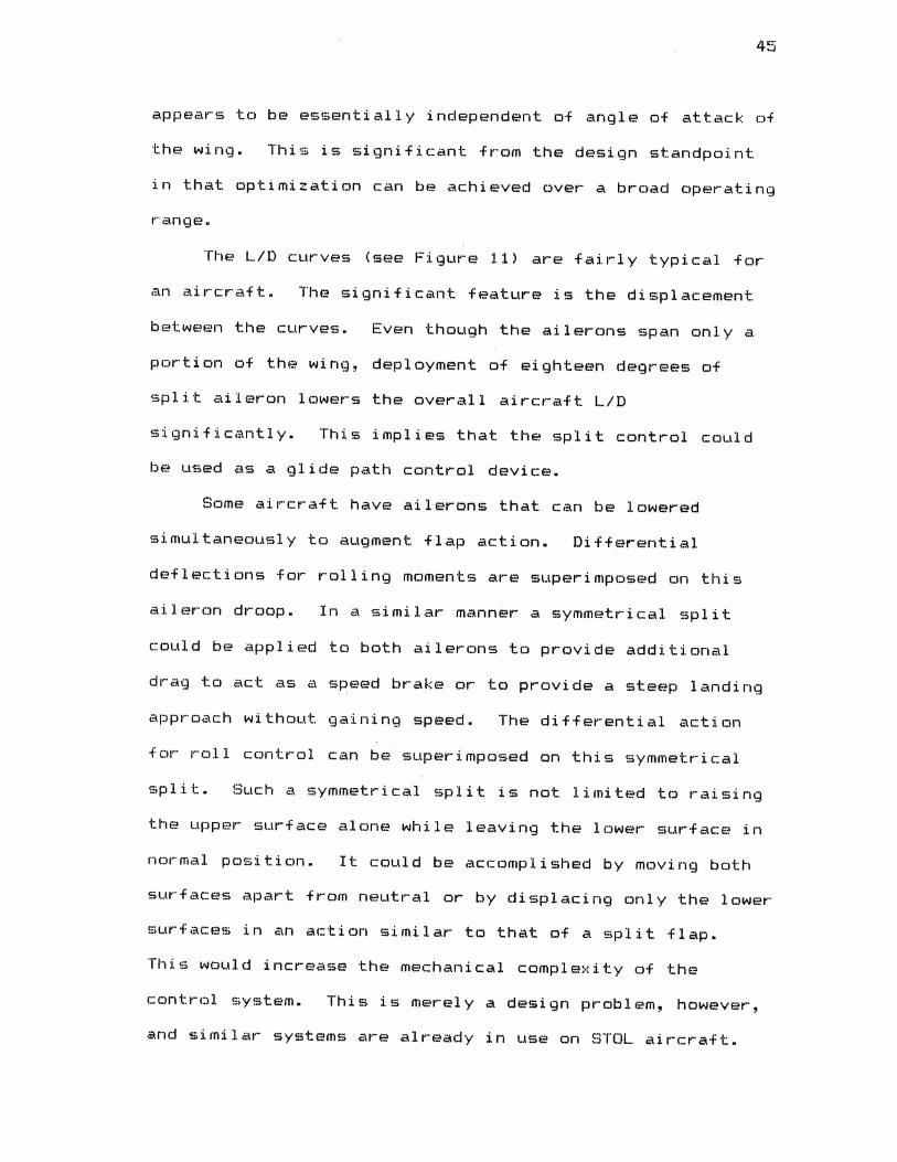
The L/D curves (see Figure 11) are fairly typical for
an aircraft. The significant feature is the displacement
between the curves. Even though the ailerons span only a
portion of the wing, deployment of eighteen degrees of
split aileron lowers the overall aircraft L/D
significantly. This implies that the split control could
be used as a glide path control device.
Some aircraft have ailerons that can be lowered
simultaneously to augment flap action. Differential
deflections far rolling moments are superimposed on this
aileron droop. In a similar manner a symmetrical split
could be applied to both ailerons to provide additional
drag to act as a speed brake or to provide a steep landing
approach without gaining speed. The differential action
for roll control can be superimposed on this symmetrical
split. Such a symmetrical split is not limited to raising
the upper surface alone while leaving the lower surface in
normal position. It could be accomplished by moving both
surfaces apart from neutral or by displacing only the lower
surfaces in an action similar to that of a split flap.
This would increase the mechanical complexity of the
control system. This is merely a design problem, however,
and similar systems are already in use on STOL aircraft.
46
As an example, an aircraft flying on approach without
flaps would have a Cl of 0.8.
the L/D is approximately 14.5.
In the clean configuration
At the same lift
coefficient with eighteen degree split deployment the L/D
drops to about 8.5, a reduction of over forty percent.
This is sufficient for glide path control. As another
example, an aircraft at high speed would have a Cl of 0.3.
For this situation L/D drops f~om 12.5 to 7.5, again a loss
of forty percent. This would serve nicely for a high speed
penetration maneuver such as performed in some instrument
flying procedures or when descending through a small
opening in a cloud layer.
Spoilers have been used successfully as glide path
control devices in the past. However few small aircraft
have them and a major wing redesign is required to install
them. The split aileron design maintains the advantage of
serving as a control surface replacement item.
• CH?-IF'TER SEVEN
CONCLUSIONS AND RECOMMENDATIONS
FOR FURTHER STUDY
The wind tunnel testing and data analysis show that
the split aileron concept provides a simple device to
counter adverse yaw. It has the unexpected property of a
modulated drag affect that permits it to be optimized over
a broad range of operating conditions. One of th~?
strengths of this design is that it could be easily
retrofitted to existing aircraft designs without changing
th~:·~ w:i. ng d€-?~~:i. gn. It would amount to a control surface
change with some modification of existing actuator
linkagf?s.
The test data showed that it can be used as an
effective glide path control device. Although this was not
the original objective, it is a bonus.
Since this was the first test of this idea~ the wind
tunnel tests were designed to establish the validity and
any unusu;:..l bl~h.-avi Dr Df the CDncept.
areas were ne~t investigated.
Consequently some
Additional testing could be done to experiment with
greater control surface deflection angles. From this
testing a detailed optimization profile for downward and
47
upward aileron settings could be established. This would
provide design of an operating linkage concept.
48
Another area for further research would be to
determine why the drag increment is modulated with angle of
attack. This result was not expected and cannot be
explained. Flow visualization techniques will probably be
required here.
Further research should be accomplished with other
airfoil sections to determine if the performance of the
split aileron is independent of the airfoil section.
Modern airfoils such as the GAW series should be
investigated.
Investigations of deep stall and extreme negative wing
angle of attack should be performed to discover any
undesirable or limiting characteristics. This research
could be performed with the original test model.
Hinge moment testing should be accomplished. This
will insure that a hinge design can be made to permit the
pilot to easily operate the ailerons with unpowered
controls. It must be insured that there are no sudden
changes or reversals of hinge moment which would create
control problems for the pilot.
A design should be made for retrofitting an existing
aircraft with this concept. The cost of producing and
marketing the design should then be determined. This will
permit assessing the financial feasibility of the concept.
A SELECTED BIBLIOGRAPHY
(1) Abbott, Ira H. and Albert E. von Doenhoff. !h~QCY gf_~ing_§!£tiQD!• New York, McGraw-Hill 1949.
<2> Davidson, M. L. E~£!!!t~_Q!~£C!ei!gn_gf_tb~ Z_!_lQ Eggt-~2lt~c-~~-~!~£b_~!mQc!~l-~!n2 I~no~l· Aeronautical Engineering Department, Wichita State University, Wichita, Kansas, 1979.
<3> Dole, Charles E. El!9ht_!h~QCY-2QQ_B~C9QYO!ffii£a· John Wiley & Sons, 1981.
(4) Garber' Paul E. "Warped Wings. II s~Ql!::!i!QQ __ gf B!c'c~ft_~!ng_Q~~!gn, American Institute of Aeronautics and Astronautics, 1980.
<5> Habluetzel, Tracy. IhC~!=Q!m!D!!QD~l_Egc;~-Q~t~ 8'9Y!§!t!gn_AQQ_B!Q!::!£t!gn_Bgyt!n!_Egc_!b! ~llt!c_H~-~!~£h_Z_K_lQ_Eggt_bg~_§Q!!~-~!n~ IYOD~!· Aeronautical Engineering Department, Wichita State University, Wichita, Kansas, 1980.
(6) Lissaman, P. B. S. "Wings For Human Powered Flight." 5~9!!::!!!gn_gf_B!c;c!ft_~!D9_Q!!!9D, American Institute of Aeronautics and Astronautics, 1980.
<7> McCormick, Barnes W. B!CQQ~D~ffi!£!L_6!CQDIY!!£aL and E!!9h!-~!£h1Di£!• John Wiley & Sons, 1979.
( f::1) Perkins, Courtland D. and Robert E. Hage. E!cfgcm!D£!_§t2P-ilitY_In2_Qgntcgl. 8< Sons, 1949.
6!CQlAD.~ John Wiley
(9) Pope, Alan and John J. Harper. bg~_§g_~gg_~!DQ I~DD!l I!!!!ng. John Wiley & Sons, 1966.
<10) Rae, William H. and Alan Pope. bg~_§Q!!Q_~!DQ !YDD!l I!!t!ng. John Wiley & Sons, 1981.
<11) Riegels, Friedrich W. B!~QfQ!!_§~;t!QQ§, London, Butterworths, 1961.
49
( 12) Shevell, Richard S. Prentice-Hall,
EYD~~ffi§O~~i§_gf_Ell9bt· Inc:. , 1983.
<13) Torenbeek, Egbert. §~ntb§§i§_Qf_§y~§QO!~ eicQl~D~-Q~ai9D• Delft University Press, Delft,Holland and Martinus Nijhoff Publishers, The Hague, Holland, 1982.
<14> Warner, Edward P. Blce!~o~_Q§§ign_E§CfQCffi~Q£§· New York, Mc:Gr·aw-Hill, 1936.
50
APPENDIXES
!'51
APPENDIX A
MODEL CONSTRUCTION
Details of the wind tunnel test medal construction are
provided as a matter of record~ The wing section chord and
span ware chosen to be consistent with the wind tunnel test
section dimensions. Based on past experience the wind
tunnel operators recommend that wing span should not exceed
70% of the test section span. This limitation minimizes
errors from wall interference. This limited span to seven
feet or less due to the ten foot test section width of the
Walter H. Beech Memorial Low Speed Wind Tunnel. A
reasonably thick wing is desired to obtain structural
strength and provide space for actuating systems. A thick
wing requires a long chord for a given airfoil section.
For a given span, a long chord leads to a low aspect ratio.
A high aspect ratio is desired to reduce wingtip effects.
Thus airfoil thickness and aspect ratio require a
compromise. An aspect ratio of seven was chosen as a
reasonable value to represent light general aviation
aircraft. This results in a wing chord of one foot and a
wing area of seven square feat.
Dimensional tolerances must be very close for wind
tunnel models to achieve reliable test data . Structural
•
53
strength is important because the aerodynamic loads of the
wind tunnel can be large compared to the model size. If
the model deforms under load it is impossible to predict
the actual angle of attack and control settings for a given
set of data. For the data to be reliable the deformations
under load must be small. Therefore it is necessary to
build in rigidity. Dimensional accuracy and rigidity are
major considerations for model construction. The model
design was based en these considerations, available
material~ and equipment.
The main structural member of the wing -is a simple
vertical spar at 25% chord. The spar is a continuous seven
foot length of 0.132 inch stainless steel milled to 1.400
inch height. The stainless was chosen for its high
strength. Ribs were placed at one foot intervals along the
span. Aluminum alloy 6061-T651 of 0.375 inch thickness was
chosen for the ribs. This thickness permitted the wing
skin to be attached by rivets driven into the ribs without
the use of flanges. Rectangular sections were cut and
milled to high dimensional tolerance to construct the one
piece ribs. All interior cutouts and holes were made
before the ribs were milled further because it was easier
to accurately locate positions for the cuts while the rib
blanks were still rectangular. Two reference holes at two
and seven inch positions of 0.1875 inch diameter were cut
along the chord line. These holes were later used to hold
the ribs in a jig fixture by use of steel dowel pins.
54
After all interior cuts were machined a carefully made
wooden airfoil was attached to the rib blank with dowel
pins and the airfoil shape was scribed onto the rectangular
aluminum rib blank. An approximation of the airfoil was
then cut by use of straight line cuts made on a vertical
milling machine. This series of cuts was made to within a
few thousandths of an inch of the airfoil shape. This
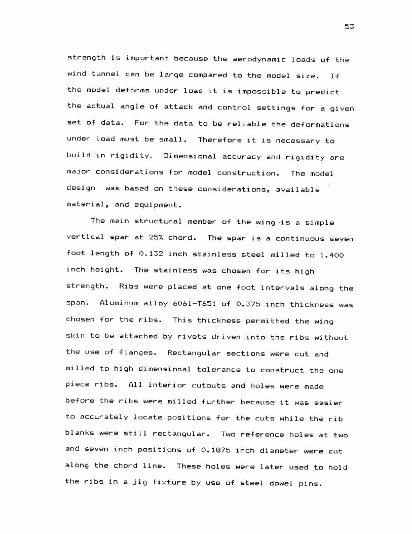
airfoil approximation was then bolted into a wooden jig
illustrated in Figure 13. A metal cutting tool was
installed in a router and used to cut the airfoil shape.
By geometrical techniques developed by the author this
wooden jig was cut in a manner such that when the router
base was guided along the outer curves~ the cutting tool
edge scribed the airfoil shape on the inside. This left a
slightly rough surface which was then smoothed by hand by a
single cross cut file.
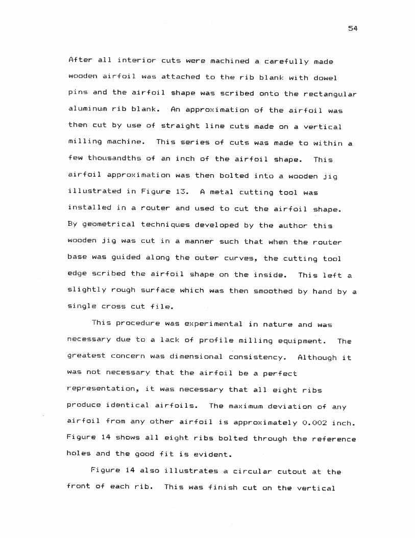
This procedure was experimental in nature and was
necessary due to a lack of profile milling equipment. The
greatest concern was dimensional consistency. Although it
was not necessary that the airfoil be a perfect
representation, it was necessary that all eight ribs
produce identical airfoils. The maximum deviation of any
airfoil from any other airfoil is approximately 0.002 inch.
Figure 14 shows all eight ribs bolted through the reference
holes and the good fit is evident.
Figure 14 also illustrates a circular cutout at the
front of each rib. This was finish cut on the vertical
Figure 13. Rib Profiling Fixture
Figure 14. Rib Sections
56
mill with all ribs bolted together to insure consistent
location. This cutout was used to install an aluminum rod
along the leading edge to establish the leading edge radius
curve when the sheet metal covering was installed.
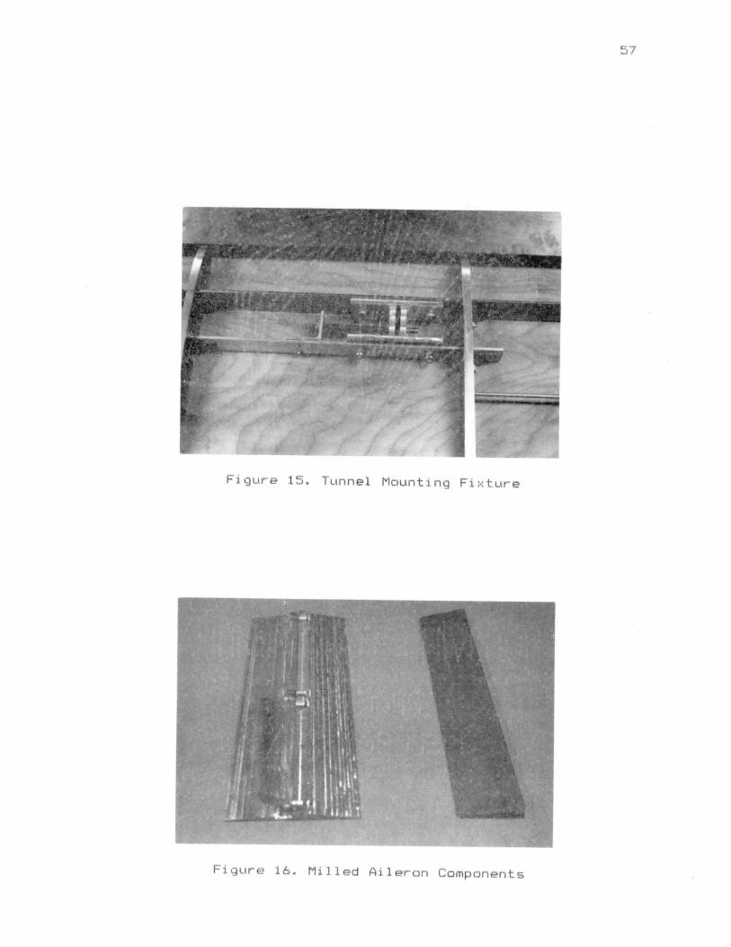
Figure 15 illustrates the spring loaded mounting
mechanisms for the two wing mounting points. A second spar
is placed between the mounting fixtures to prevent the lift
loading from twisting the main spar. This secondary spar
was made of aluminum and.is not primary structure.
Actuation of the mounting device was provided through small
slots in the lower wing surface.
The ailerons were constructed for high torsional
strength so that a single point attachment could be used
for setting deflections. The upper and lower aileron parts
were milled from single pieces of 6061-T651 aluminum.
Figure 16 shows the aileron parts.
Some means to set aileron deflections was necessary.
An internal mechanism is more streamlined but the shallow
airfoil thickness at the aileron hinge point provides poor
mechanical advantage. "Blow down" of control surfaces is a
common problem of wind tunnel models. The aerodynamic
loads tend to cause the surfaces to deflect somewhat from
the static setting. External brackets were used with an
indexing arrangement for bolting the aileron surfaces
rigidly in place. The index permitted three degree
increments of aileron position. The indexing bracket was
attached externally to the wing structure and the upper
57
Figure 15. Tunnel Mounting Fixture
Figure 16. Milled Aileron Components
aileron surface was secured to the indexing bracket. A
single small bolt at the trailing edge attached the lower
58
aileron surface to the upper surface. When the split mode
operation was desired this small bolt was removed and two
small drive pins in the indexing bracket were driven
forward to capture the lower surface at the zero deflection
position. The axis of the drive pins was tapered slightly
to eliminate all slack from the ailerons.
for an illustration of this arrangement.
See Figure 17
The ailerons were sized to cover two feet of span on
each wing tip. The chord length of the ailerons was chosen
at 30% chord or 3.6 inches. This is a figure typical of
control surface design.
Small rods threaded on both ends were placed between
ribs and used for rigging purposes only. The structure was
rigged into alignment using a precision straight edge along
the leading edge <see Figure 18). Figure 19 shows the
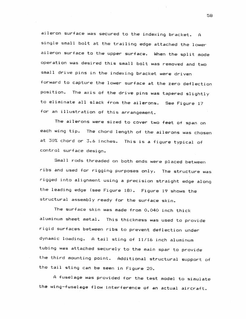
structural assembly ready for the surface skin.
The surface skin was made from 0.040 inch thick
aluminum sheet metal. This thickness was used to provide
rigid surfaces between ribs to prevent deflection under
dynamic loading. A tail sting of 11/16 inch aluminum
tubing was attached securely to the main spar to provide
the third mounting point. Additional structural support of
the tail sting can be seen in Figure 20.
A fuselage was provided for the test model to simulate
the wing-fu5elage flow interference of an actual aircraft.

60
Figure 19. Complete Structure Prior to Covering
Figure 20. Tail Sting Components

This arrangement provided the best simulation of actual
aircraft flow conditions to enhance the applicability of
the results. The fuselage was constructed by bonding
planks of wood under pressure and turning to final
dimension on a lathe. The upper and lower parts of the
61
fuselage were provided with an internal slot to fit tightly
on the tail sting. This increased the rigidity of the tail
sting to prevent flexing of the tail sting and change of
the angle of attack under load.
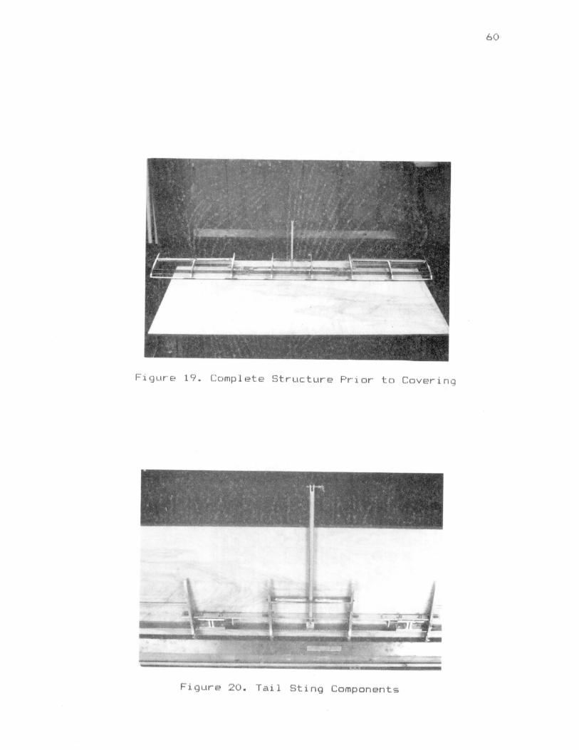
Figure 21 shows the complete model installed in the
wind tunnel for testing with the ailerons in neutral
positions. Figure 22 shows the model in the tunnel with
maximum split on the ailerons.
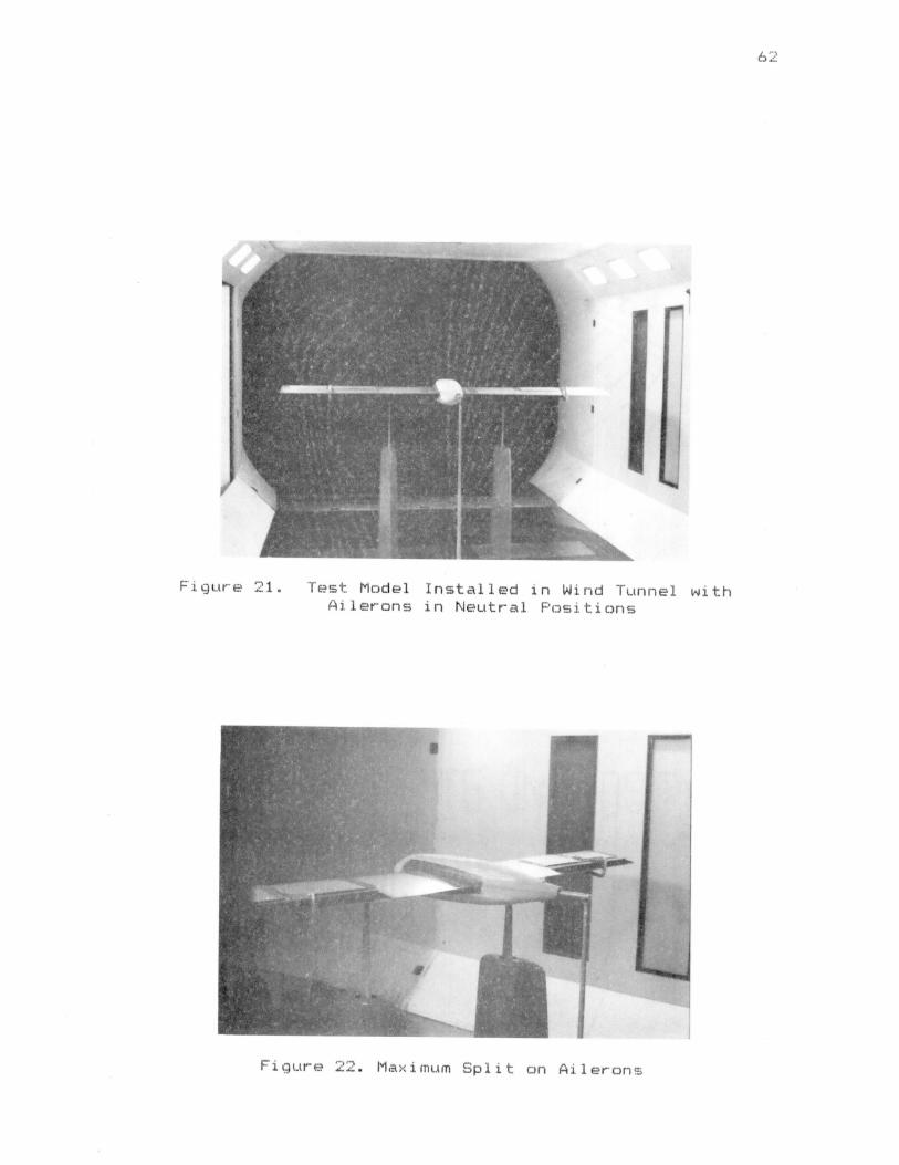
Figure 21. Test Model Installed in Wind Tunnel with Ailerons in Neutral Positions
Figure Maximum Split on Ailerons
6~ L
APPENDIX B
WIND TUNNEL NUMERICAL DATA
64
f I c ~ ! L~
' I., l ~ l j
~ ~ 1<~:~:
r • .~ It:
n II~ ~ q
' I~ ~~ I~ ~ I~
1-!-"' u I I (] o:~ I~ I~ ~i ~~ I~ I~ ~~· f~ ·~ ! ~ ~ :r-: IJi ~~ ~ ~ I~
I I .... _ ... 'i lJ 1- -1. 11-I_,
~ c c c li: ' ~ I~
ol~ I~ :s I~ I~ ~~ :u 11]1nl I 1-: 1"1 I'' 1-s ll' lq ~ ~1:: ~~ I~ I~ I~ I~ ~~ I~ I~ ~~
_,... N"'
tt~ I~ 1-~ II : ....
'l'J 11'\o 1-: 11 I~ .air- Itt Ia- ~ ~ I~ I~ I~ I~ I~ I~ ~~ I~ I~ I~ I~ ~~~
~~- I~ 1-~ I~ b
I~
~ I I I ll ~ ..... ~
~ I I ~ -~ ~ _ ....
.. .II J ~ ~ -... - - ~
~ ~~~ ~ ~ ll ~
~~ .: ...
~J ~~ ~ 1t u ~
.J c ( 0 IJ~ J I~ ~ j IJ I~ ~ Oleo? ~ ~ I~ j 0 () 00 ~ \..! -.: - ..s ..S)
~ 1 j J -rl I~ 1-:~- f&.1 .JI t" I~ f' ~ ::: ·~ !!l I~ ·~ I~ I~ I~ :a.: ~ 11
rl -I~
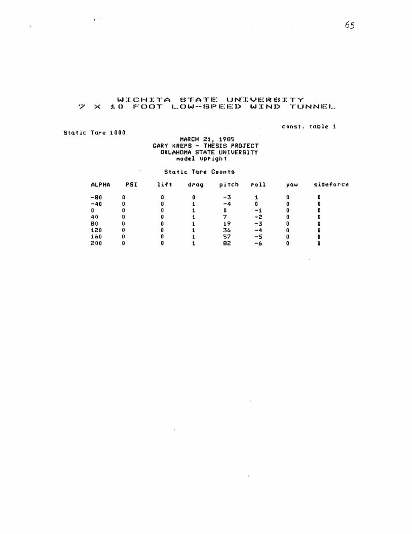
65
WICHITA STATE UNIVERSITY 7 X ~0 FOOT LOW-SPEED WIND TUNNEL
c:onst. tllble 1 Static T11re 1000
MARCH 21, 1985 GARY KREPS - THESIS PROJECT
OKLAHOMA STATE UNIVERSITY Model upriQht
Stat.lc Tare Countl!l
ALPHA PSI lift dra9 pitch roll yaw t~ideforce
-eo 0 0 0 -3 1 0 0 -40 0 0 1 -4 0 0 0 0 0 0 1 0 -1 0 0 40 0 0 1 7 -2 0 0 80 0 0 1 19 -3 0 0 120 0 0 1 36 -4 0 0 160 0 0 1 S7 -s 0 0 200 0 0 1 82 -6 0 0
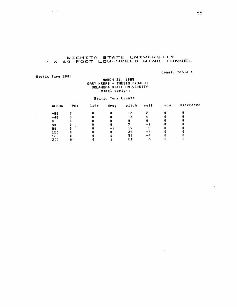
66
W :1: C H :1: T A B T A T 1::: U N :1: V 1::: I~ ~;:; :1: T Y '? X :1. 0 FDDT I ... DW····SP EI:::I> W :1: ND TUNN1:::1 ...
const. table 1 Static Tare 2000
MARCH 21 1 1985 GARY KREPS - THESIS PROJECT
OKLAHOMA STATE UNIVERSITY Model upright
S til t.i c Tare Counts
ALPHA PSI lift drag pitch roll yaw sideforce
-so 0 0 0 -3 2 0 0
-40 0 0 0 -3 1 0 0 0 0 0 0 0 0 0 0 40 0 0 0 7 -1 0 0 80 0 0 -1 19 -2 0 0 120 0 0 0 3S -4 0 0 160 0 0 1 56 -4 0 0 200 0 0 1 81 -6 0 0
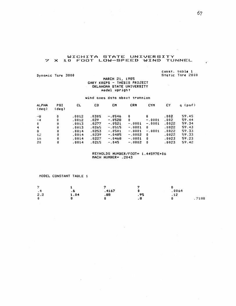
W :1: C H :1: T A B TAT m: UN :1: VIE I~ S :1: T Y '7 X :1. 0 F D 0 T 1. .. 0 W ···· ~:; P 1::: 1::: X> ' W :1: N l) T U N N 1::: 1. •. •
const. table 1 DynoM.i.c: Tare 3000 Stat.ic Tare 2000
MARCH 21, 1985 GARY KREPS - THESIS PROJECT
OKLAHOMA STATE UNIVERSITY MOdel upr .i.gh t
w.i.nd axes data about trunnion
ALPHA PSI CL CD CH CRH CYM CY q <psf') (deg> <deg>
··8 0 .0012 .0305 -,0546 0 0 .002 S9.4S -4 0 .0012 . 029 -. 0528 0 -.0001 .002 59.44 0 0 .0013 '0277 -, OS21 -.0001 -.0001 .0022 59.34 4 0 .0013 . 026S -.OS1S -.0001 0 .0022 59.4:3 8 0 .0014 '0253 -.0501 -.0001 -.0001 .0022 59.33 12 0 .0014 . 0239 -. 0485 -.0002 0 .0022 59.33 16 0 .0014 . 0227 -. 0468 -.0001 0 .0023 S9.23 20 0 .0014 .021S -. 04S -.0002 0 .0023 59.42
REYNOLDS NUMBER/FOOT= 1.44S97E+06 MACH NUMBER= .2043
MODEL CONSTANT TABLE 1
7 1 7 7 0 .4 .6 .4167 0 . 0064 2.2 1.04 .as .9S .12 0 0 0 .a 0 . '7188

68
W :a: C H :1: "Y" A ~=~ 'T" A 'Y' m: l.J N :1: V m: I~ m :1: T Y '7 X ::1. 0 1::· C:J 0 T 1 •.• C) W ···· ~=~ 1::~~ m: 1::: l) W :1: N l) T U N N m: 1...
Run nul'lber 1 Stat .i.e: Tare 1000 DynaMic Tare ~~ 0 0 o const. table 1
MARCH 21 1 1985 GARY KREPS - THESIS PROJECT
OKLAHOMA STATE UNIVERSITY l'lodel upr.l.ght
W.i.nd AX !IS Data
ALPHA PSI CL CD CM CRM CYM CY q <psf'> < deg > (deg)
-6.27 0 -.3786 . 0308 -.0258 -.0026 -.0002 .0004 59,32 -4.15 0 -.2102 ,0238 -.0194 -.0029 -.0001 .0004 59.32 "'"~~I 02 0 -.0321 . 0203 -,0115 -.0028 -.0001 .0003 59.32 . 1 0 '148 '0206 -.0041 -.0025 -.0001 .0001 59.22 2.23 0 .3199 I 0244 .0034 -.0031 -.0002 .0002 59.21 4.35 0 .4948 '0321 .01 -.0032 -.0002 .0001 59.21 (). 47 0 .6643 .0434 .0168 -.0029 -.0001 -.0001 58.91 B.S9 0 .8361 • 058 . 0224 -.0028 -.0001 .0001 58.91 10.7 0 .988 .0757 .0283 -.0024 -.0001 0 58.62 12.76 0 1.0715 .1184 ,0099 -.0054 -.0001 .0008 S8.S2 1.3.79 0 1.1134 .1339 ,0083 -.0069 -.0002 .0016 58.35 14.82 0 1. 1SS6 .1492 .0051 -.008 -.0002 .0033 58.28 15.82 0 1.1655 .1?38 -. 004 -.0062 0 .0024 58.06 16.81 0 1.1457 .1969 -. 0152 -.0075 -.0021 -. 0035 57.94 i 7. Bi 0 1.1447 .2166 -.0212 -.0123 --.0031 -. 003? 57.6 18.83 0 1.1751 .2364 -. 02S -.0063 -.003 -.0048 57,65 19.83 0 1.1693 .2696 -.0439 .OO?S -. 002 -. 005 S7.SS 20.82 0 1.1521 .2871 -. 0524 .0186 -.0002 -.ooss 57.51
REYNOLDS NUMBER/FOOT• 1.40282E+06 MACH NUMBER= .201
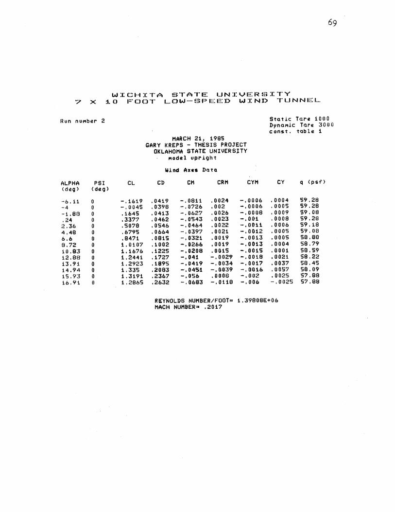
WICHITA STATE UNIVERSITY '7 X ::1. 0 F C) 0 T 1... C) W ···· S P E t::: l> W :1: N l) T U N N 1::: 1...
l~un nuMber 2 Stet .i.e: Tare 1000 DynaMic T11re 3000 const. to.ble 1
MARCH 21, 1985 GARY KREPS - THESIS PROJECT
OKLAHOMA STATE UNIVERSlTY folodel upr.i.ght
Wind' A us Dr.ttQ
ALPHA PSI CL CD CM CRM CYM CY q <psT> < deg > (deg>
-6. i1 0 -.1619 .0419 -. 0811 .0024 -.0006 .0004 59.28 ·-4 0 -.0045 . 0398 -. 0726 .002 -,0006 .ooos 59.28 ··1. 88 0 .1645 . 0413 -.0627 .0026 -.0008 .0009 59,08 . 24 0 .3377 . 0462 -.0543 .0023 -. 001 .oooa 59.28
;.: .36 0 .5078 . 0546 -.0464 .0022 -.0011 .0006 59.18 4.48 0 .6795 . 0664 -.0397 .0021 -.0012 .ooos S9.08 6.6 0 .8471 . 081S -.0321 .0019 -.0013 .ooos sa.ae 8.72 0 1. 0107 .1002 -. 0266 ,0019 -.0013 .0004 58.79 10.83 0 1.1676 .1225 -' 0208 .0015 -.001S .0001 58.59 12.8!3 0 1.2441 .1727 -.041 -.0029 -.0018 ,0021 58.22 13. 9j, 0 1.2923 .1895 -.0419 -.0034 -.0017 .0037 S8.4S 14.94 0 1.33S .2083 -. 0451 -,0039 -.0016 .OOS7 sa. o9 15.93 0 1.3191 .2367 -, OS6 .0008 -. 002 .0025 5?.88 16.91 0 1.2865 .2632 -.0683 -. 0118 -. 006 -.0025 57.88
REYNOLDS NUMBER/FOOT= 1.39808E+06 MACH NUMBER= .201?

70
W :1: C H :1: T A ~:) T A T m: UN :1: V a::: a~ ~;; :1: T Y '7 X ::1. 0 F Cl Cl T 1... D W ···· B P a::: a::: X> W :t: N l) T U N N 1::: 1...
Run nuMber 3 Static Tr.1re 1000 Dyn<JMic T<Jre 3000 c:onst. t<Jble 1
MARCH 21 1 1985 GARY KREPS - THESIS PROJECT
OKLAHOMA STATE UNIVERSITY MOdel upright
W.Lnd A us Data
ALPHA PSI CL CD CM CRM CYM CY q <psf> < deg > ( d eg)
-··6' 14 0 -. 199S . 0382 -. 0736 .001S -.0003 .0007 S9.S6 -4.03 0 -.0381 . 03SS -. 0649 .0013 -.0003 .0006 59.46 -· 1. 91 0 .1251 .0363 -. OSS3 .002 -.ooos .0008 59' 17 .21 0 .3012 .0407 -. 0467 .0018 -.0006 .0008 59.36 ~~. 34 0 . 4'741 . 0483 -. 0394 .0014 -.0008 .0008 59.36 4.46 0 .6467 .OS99 -. 0328 .0013 -.0009 '0 0 0'? S9.27 6.58 0 .8132 .0743 -.0254 .0009 -.0009 .0009 59.07 8.69 0 .9786 '0922 -' 0189 ,0008 -.0008 .001 59.07 10.8 0 12.86 0
1. 131,8 '1137 -.0132 .0006 -.0009 .001 58.88 1.2086 .1619 -.0318 -.0035 -.0013 .0022 S8.6
13.8'? 0 1.2625 .1792 -. 0351 -,0045 -.0013 .0035 S9.S3 14.92 0 1.304 '197 -. 0369 -.OOS4 -.0013 .0055 S8.S6 15.94 0 1.3235 .2194 -.0438 -.0039 -.001 .0056 S8.42 t6.94 0 1.3321 .2443 -.OS -.0023 -.0009 .OOS3 S8.3 17.9 0 1.2697 .2721 -.0623 -.0111 -.0049 -.0021 58.21
REYNOLDS NUMBER/FOOT= 1.3BS90E+06 MACH NUMBER= .2023

71
WICHITA STATE UNIVERSITY '7 X :1. 0 F 0 Cl T 1... 0 W ···· ~:; P E 1::: I) W :1: N X> T l.J N N 1::: 1 ...
Run nuMber 4 Stat .i.e Tare tOIIO DynaMic Tare 3000 c:onst. table 1
MARCH 21, 1985 GARY KREPS - THESIS PROJECT
OKLAHOMA STATE UNIVERSITY MOdel upright
Wind Axes D.ata
ALPHA PSI CL CD CH CRM CYM CY q <psf> (dtQ) <deg>
-6.17 0 -.2368 . 035 -. 0648 .0003 -.0002 .0003 59.55 ·-4. OS 0 -. 0758 .0318 -. 0562 .0001 -.0001 .0004 59.5S ·-1. 94 0 .0883 . 0319 -. 0468 .0003 -.0002 .0006 59.25 .19 0 .267 . 0353 -. 038 .001 -.ooos .ooos 59.25 2.31 0 .4394 .0424 -.0307 .0007 -.0006 .0006 59.15 4.43 0 .6111 .0531 -. 0239 .0003 -.0007 .0006 59.05 6.SS 0 .783 . 0673 -.0168 .0003 -.0006 .0006 58.96 8.67 0 .9452 . 0845 -.0102 .0004 -.0006 .0009 58.86 i 0 . 7!3 0 1.1 .1053 -' 004 .0006 -.0008 .0009 58.67 12.83 0 1.1773 '1534 -. 0228 -.0033 -.0011 .0025 58.39 13.87 0 1.2233 '1703 -. 0252 -. 0049 -.0011 ,0036 58.22 14.83 0 1.1766 .1962 -. 039S -. 0073 -. 0044 -.0003 sa .12 15.85 0 1.2048 .2158 -. 0437 -.0108 -.0049 -.0015 sa. o7 16.86 0 1.218 .2403 -.0512 -. 0122 -. 0052 -.0013 57.84 17. 8!3 0 1.2368 .2596 -. 0528 -.0111 -.0053 -.001 57.79
REYNOLDS NUMBER/FOOT= 1.37593E+06 MACH NUMBER= .2015

72.
WICHITA STATE UNIVERSITY 7 X ~0 FOOT LOW-SPEED WIND TUNNEL
Run nuMber S Static: Tare 1000 DynaMic Tare 3000 const. table 1
MARCH 21 1 1985 GARY KREPS - THESIS PROJECT
OKLAHOMA STATE UNIVERSITY Model upright
W.i.nd Axes Data
ALPHA PSI CL CD CM CRM CYM CY q < psf> <de g > <de g >
·-6' 2 0 -.2769 '0304 -.0551 0 -.0001 0 59.43 -4' 08 0 -' 1138 '0263 -. 0471 -.001 -.0001 0 59.33 ··1 '96 0 .0508 '0258 -. 0377 -.0006 -,0001 .0002 59.14 .16 0 .2264 . 0283 -.0281 -.0004 -.0003 .0002 59.23 2,28 0 .3987 .0343 -. 02 -.0001 -.0005 .0003 59.33 4.4 0 .5706 '0441 -.0127 -.0001 -.ooos .0002 59.13 6.52 0 .7406 . 0575 -. 0055 .0001 -.ooo5 .0002 58.84 8.64 0 .9069 .0739 .0004 -.0004 -.0005 .0001 59' 04 10 '75 0 1.0576 • 0941 .0059 -.0004 -. 0 0 04 -.0004 58.85 12 '81 0 1.1404 '1408 -.0124 -.0051 -.ooos .0014 58.56 13.83 0 1.1755 .1587 -. 0179 .0032 -.0004 -.0001 58.5 14.84 0 1.1815 .1843 -. 0273 .0005 -.0003 .0016 58.48 15.83 0 1.1713 .2015 -.0346 -' 0113 -' 0042 -.0029 58.44 16 '8:"3 0 1.1779 .2247 -.0399 -.0126 -.0045 -.0027 58.31 j.7 .84 0 1.1853 .255 -' 0532 -.009 -.0013 -.0017 58.1
REYNOLDS NUMBER/FOOT= 1, 36739E+06 MACH NUMBER= .2021
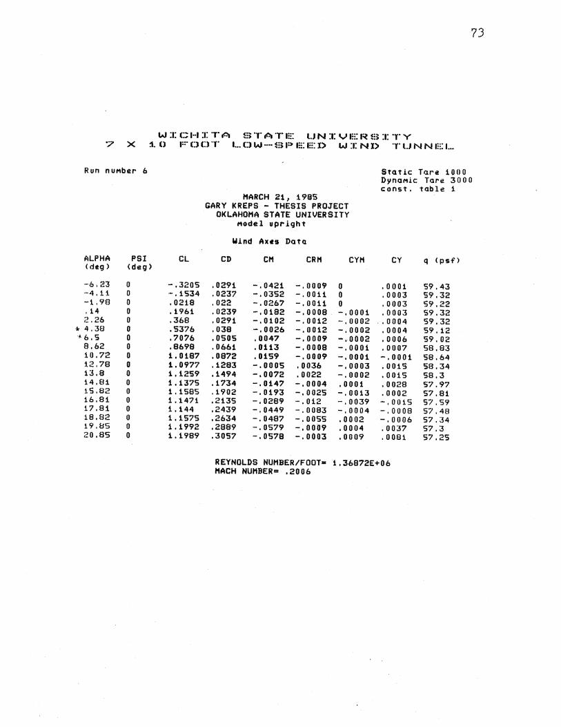
73
WICHITA STATE UNXVERBXTY '7 X j, 0 1::· DDT 1... CJ W ···· ~:; 1:) m: 1::: I) W :1: N X> T l.J N N 1::: 1...
Run nuMber 6 Static Tare 1000 DynaMic Tare 3000 const. table 1
MARCH 21 1 1985 GARY KREPS - THESIS PROJECT
OKLAHOMA STATE UNIVERSITY Model upright
W.i.nd Axes Data
ALPHA PSI CL CD CM CRM CYM CY q <psf'> < deg) <deg)
-·6' 23 0 -.3205 '0291 -.0421 -' 0009 0 .0001 59.43 -4. u. 0 -.1534 '0237 -' 0352 -' 0011 0 .0003 59.32 -1 '98 0 .0218 '022 -.0267 -.0011 0 .0003 59.22 .14 0 .1961 .0239 -.0182 -' 0008 -.0001 .0003 59.32 ;z ,26 0 .368 . 0291 -.0102 -.0012 -.0002 .. 0004 59.32
* 4 '38 0 .5376 . 038 -.0026 -. 0012 -.0002 .0004 59' 12 -1-6,5 0 .7076 .osos ,0047 -.0009 -.0002 .0006 59' 02 8.62 0 .8698 '0661 '0113 -.0008 -' 0001 .0007 58.83 10 '72 0 1.0187 .0872 .0159 -.0009 -.0001 -' 0001 58.64 :t;~ '78 0 1. 0977 .1283 -.0005 .0036 -.0003 .0015 58.34 13.8 0 1.1259 .1494 -.0072 .0022 -.0002 .0015 58.3 14.81 0 1.1375 .1734 -.0147 -.0004 .0001 .0028 57.97 15.82 0 1.1585 '1902 -. 0193 -.0025 -.0013 .0002 57.81 16.81 0 1.1471 .2135 -. 0289 -.012 -' 0039 -.0015 57.59 17.81 0 1.144 .2439 -. 0449 -.0083 -.0004 -.000!3 57.48 18.B2 0 1.1575 .2634 -. 0487 -.DOSS .0002 -.0006 57.34 i9.8S 0 1.1992 .2889 -. 0579 -.0009 .0004 .0037 57.3 20 .as 0 1.1989 .3057 -. 05?8 -.0003 .0009 .0081 57.25
REYNOLDS NUMBER/FOOT• 1.36872£+06 MACH NUMBER= .2006
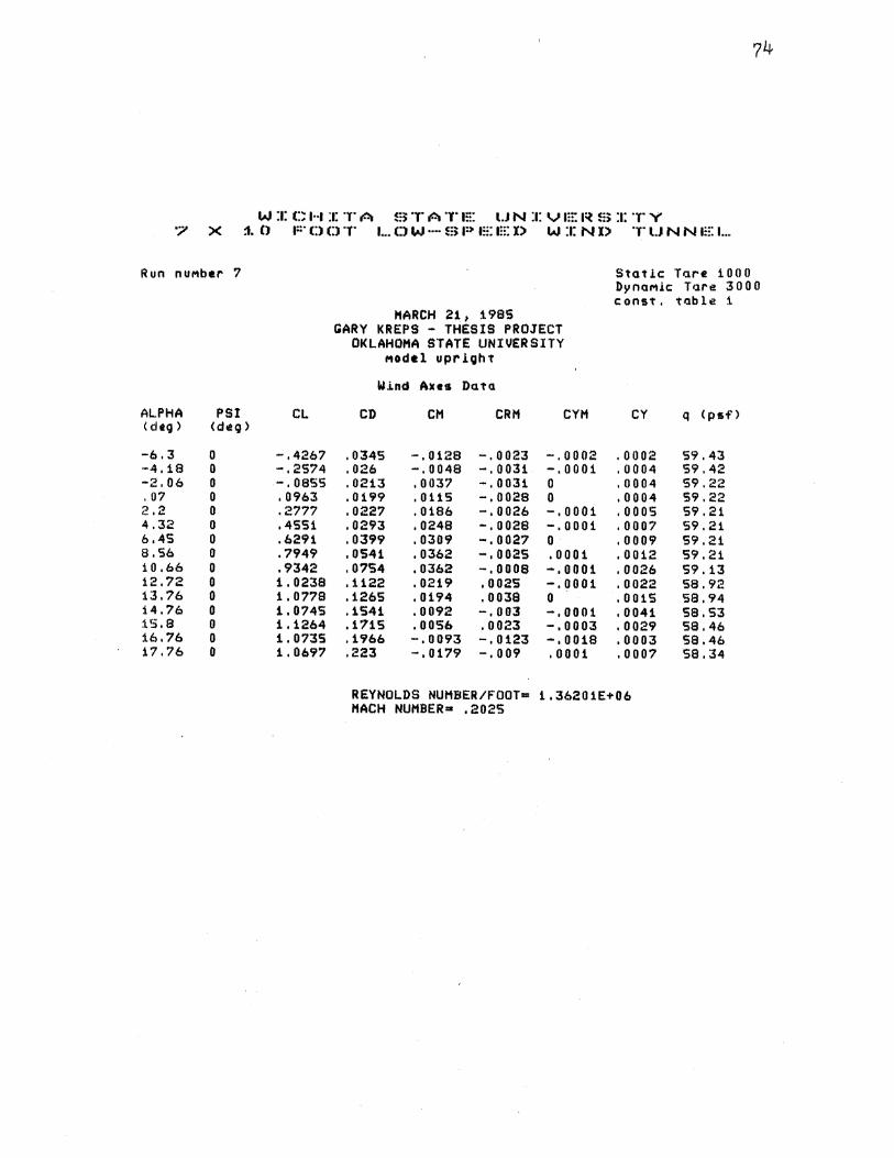
74
W :1: C H :1: T A ~:; T A T 1::: l.J N :1: V m: I~ $ :1: T Y "7 X ::1. () 1::· 0 D T 1. .. C) W ···· ~!) 1:> 1::: 1::: I> W :1: N X> T U N N m: 1. ..
Run nuMber 7 Static Tare 1000 DynaMic Tore 3000 const. table i
MARCH 21 1 :1.985 GARY KREPS - THESIS PROJECT
OKLAHOMA STATE UNIVERSITY Model upright
W.i.nd Axe• Datu
ALPHA PSI CL CD CM CRM CYM CY q <psf> < cltg) (deg >
-6.3 0 -.4267 '0345 -. 0128 -.0023 -.0002 .0002 59.43 ·-4.18 0 -.2574 . 026 -. 0048 -.0031 -.0001 .0004 S9.42 -2.06 0 -.oass '0213 ,0037 -.0031 0 .0004 59.22 .07 0 . 0963 . 0199 . 0115 -.0028 0 .0004 59.22 2.2 0 .2777 . 0227 .0186 -.0026 -.0001 .ooos 59.21 4.32 0 .4551 . 0293 ,0248 -. 0028 -.0001 .0007 59.21 6.4S 0 .6291 '0399 .0309 -. ooa? 0 .0009 59.21 8,56 0 .7949 .0541 .0362 -' 0025 . 0001 .0012 59.21 10.66 0 .9342 . 0?54 '0362 -.0008 -.0001 .0026 59' 13 12.72 0 1.0238 .1122 .0219 .0025 -.0001 .0022 58.92 13.76 0 1.0778 .1265 .0194 .0038 0 .0015 58,94 14.76 0 1.0745 .1541 .0092 -. 003 -.0001 .0041 58.53 :1.5.8 0 1.1264 .1715 .0056 .0023 -.0003 .0029 58.46 16.76 0 1.0735 .1966 -,0093 -.0123 -.0018 .0003 58.46 17.76 0 1.0697 .223 -' 0179 -.009 .0001 .0007 58.34
REYNOLDS NUMBER/FOOT= 1.36201E+06 MACH NUMBER .. . 2025
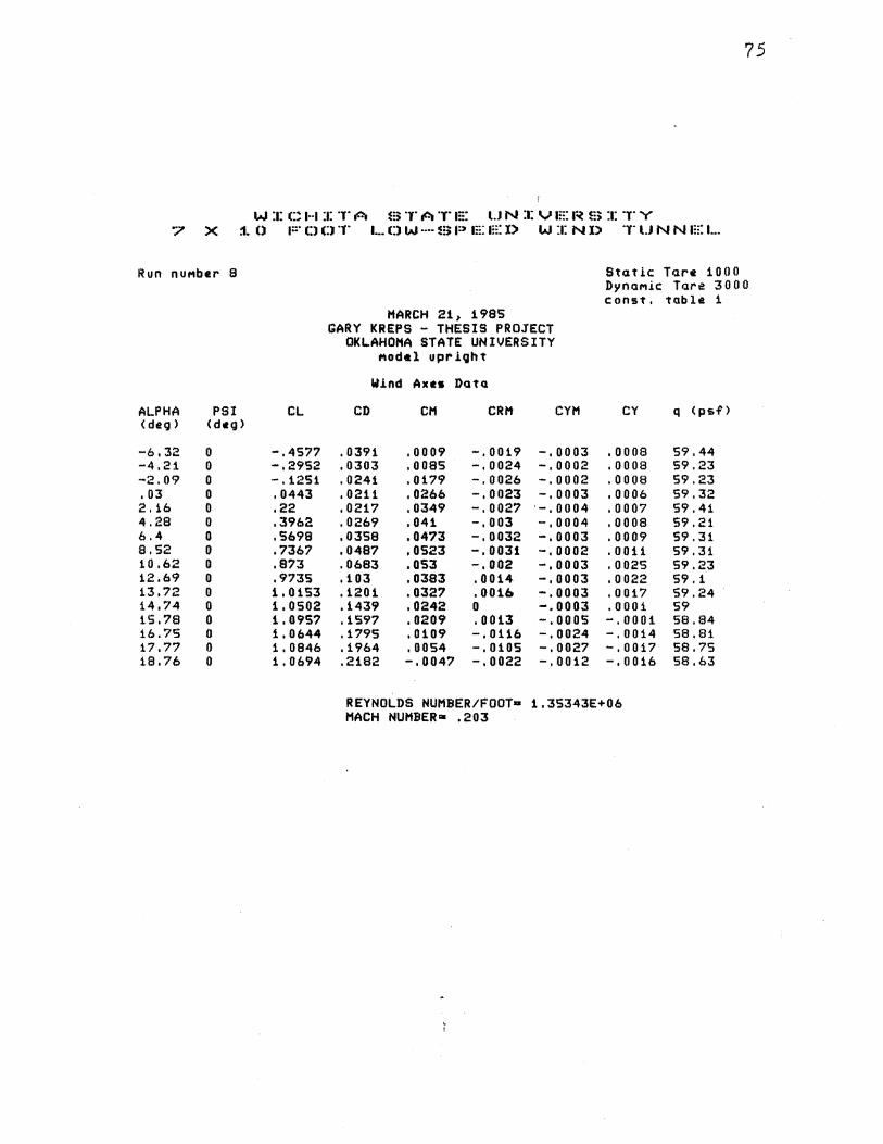
75
W :1: C H :1: T A m T A 'l" 1::: l.J N :1: V 1::: I~ ~=~ :1: T Y '7 X ::1. () 1::· (;) (;) T 1. •• 0 W ···· ~=~ P m: 1::: l) W :1: N X> T U N N 1::: 1...
Run nuMber 8 Static Tare 1000 DynaMic Tare 3000 const. tab 1 e 1
MARCH 21 t 1985 GARY KREPS - THESIS PROJECT
OKLAHOMA STATE UNIVERSITY Modlltl upriQht
W.ind Axes Data
ALPHA PSI CL CD CM CRM CYH CY q <psf) <deg> (deg>
-6.32 0 -.4577 .0391 .0009 -. 0019 -' 0003 . 0008 59.44 -4.21 0 -.2952 '0303 .0085 -.0024 -.0002 .0008 59.23 -2.09 0 -' 1251 . 0241 .0179 -.0026 -.0002 .0008 59.23 .03 0 .0443 .0211 .0266 -.0023 -.0003 ,0006 59.32 2.16 0 .22 ,0217 .0349 -.0027 -.0004 .0007 59.41 4.28 0 .3962 . 0269 .041 -.003 -,0004 .0008 59.21 6.4 0 .5698 .0358 . 04'73 -.0032 -.0003 .0009 59.31 8.52 0 .'7367 .0487 • 0523 -.0031 -.0002 . 0011 59.31 10.62 0 .8?3 . 0683 .053 -.002 -,0003 .002S 59.23 12.69 0 .9735 .103 .0383 .0014 -.0003 .0022 59.1 13.72 0 1.0153 .1201 .0327 . (}0 U:t -.0003 .0017 59.24 14.74 0 1.0502 .1439 . 0242 0 -. 0003 .0001 59 15.78 0 1.095? .1597 .0209 . 0013 -.ooos -.0001 58.94 16.75 0 1. 0644 .1795 .0109 -. 0116 -.0024 -.0014 58.81 17.77 0 1.0846 .1964 .0054 -. 0105 -.0027 -.0017 58.75 18.76 0 1.0694 .2182 -.0047 -.0022 -.0012 -.0016 58.63
REYNOLDS NUMBER/FOOT• 1.35343E+06 MACH NUMBER• .203

?6
WICHITA STATE UNIVERSITY '7 X :1. 0 1::· Cl (:) T 1... Cl W ···· ~;; P 1::: E X> W :1: N D T l.J N N 1::: 1 ...
Run nuMber 9 Static Tare 1000 DynaMic Tare 3000 c:onst. tab 1 e: 1
MARCH 21 1 :1985 GARY KREPS - THESIS PROJECT
OKLAHOMA STATE UNIVERSITY Model upright
loHnd AU15 Data
ALPHA PSI CL CD CM CRM CYM CY q < p sf'> < deg > ( deg >
-6.35 0 -.5009 . 0454 .0094 -.0041 -.ooo5 .0008 59.45 ·-4. 24 0 -.3323 . 0352 .0184 -.0041 -.ooos . 0011 59.34 -2 I j,2 0 -.1669 . 0283 .0279 -.0037 -.0005 .001 59.54 0 0 .0041 .0243 .0376 -. 003 -.ooos . 0011 59.33 2.12 0 .1702 . 0234 .0466 -. 0032 -.0006 . 0011 59.42 4.25 0 .3478 . 0269 .054 -.0033 -.0007 .0012 59.42 6.37 0 .5165 .. 0341 .0604 -.0039 -.ooo5 . 0011 59.31 !3.48 0 .6813 .045 .0661 -' 0049 -,0003 .0006 59.21 10.6 0 .841 .0593 .0708 -.0053 -.0002 .0006 59.31 12.67 0 .947 '0942 .0566 -.0079 -. 0001 .0001 59.28 13.7 0 .983 .11 ,051 0 -.0002 .0015 59.22 14.74 0 1.0394 '1251 .0483 .0012 -.0003 -.0004 59.25 15.73 0 1.0351 .1532 .0316 -.0053 .0001 .0018 59.14 16.74 0 1.0389 .1702 .0261 -.0071 -.0006 .0002 58.89 17.73 0 1. 03 '1978 . 0114 -.0035 .0012 .0008 58.78
REYNOLDS NUMBER/FOOT= 1.34750E+06 HACH NUMBER= .2032

77
WICHITA STATE UNIVERSITY '7 X j, () F 0 D T 1 ... C) W ···· =::;: 1=> 1::: 1::: I> W :1: N X) T l.J N N E 1 ...
Run nuMber 10 Stat .i.e: T11re 1000 DynaMic Tr.1re 3000 c:onst. tr.lble 1
MARCH 21, 1985 GARY KREPS - THESIS PROJECT
OKLAHOMA STATE UNIVERSITY Model upright
W.Lnd Axes Data
ALPHA PSI CL CD CM CRH CYM CY q < psf> < deg > < deg >
-6.38 0 -.5356 . 0509 .0187 -.oo55 -.0007 .0007 59.26 -4.26 0 -.3646 . 0399 .0277 -.0051 -.0006 .001 59o35 -2 014 0 -0 1959 0 0327 o0373 -o0048 -o0006 o0012 59o25 -0 02 0 -.0267 o0283 .0484 -o0031 -o0006 o001 59.34 2 0 1 0 .1356 0 027 .o58S -. 0026 -.0008 o0009 511'o34 4.22 0 .308 0 0299 .0657 -.003 -,0008 o0007 S9o43 6o33 0 .4717 o0358 '0725 -.0037 -.0007 o0007 59o33 8o45 0 .6361 o04417' o0787 -.004 -.0006 o0009 59o32 10 0 56 0 .791 0 0574 '0837 -.004 -.ooo5 o0008 59o32 12o62 0 .8744 0 0928 o0657 -.ooo5 -.0007 .0022 59o2 13o67 0 o9457 01053 .065 .0003 -o0004 oOOOB 59 0 02 14o66 0 o9394 01322 o0504 -.0041 .0001 o0008 59.01 iS o 6°7 0 o9522 .1524 .0411 -. 0022 .002 .00:1.9 58o77 16o7 0 . 98;:!8 01731 o034 -.0004 o0038 .0046 58o52 i7o7i 0 1o0067 o1931 0 0224 -o0008 o0027 .0048 S8o48
REYNOLDS NUMBER/FOOT= 1o33873E+06 MACH NUMBER= .2027
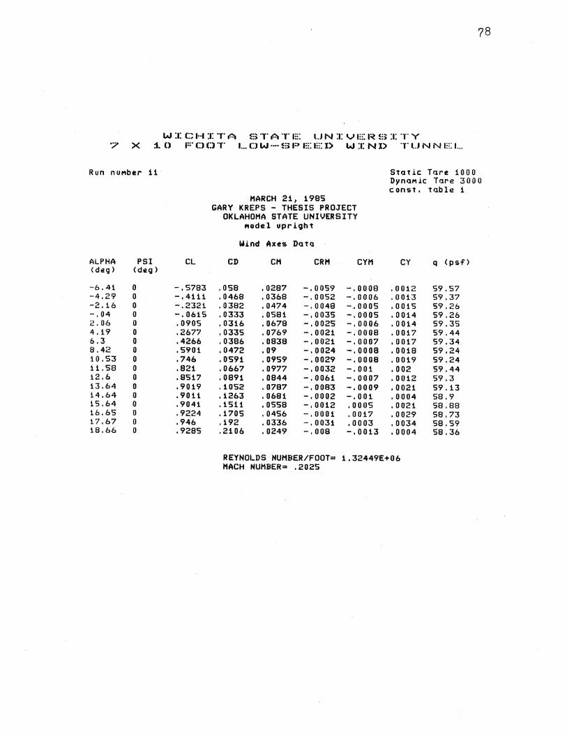
78
W :1: t::: H :1: T A ~=~ T A T 1::: l.J N :1: V 1::: I~ !:~ :1: T Y "7 X :1. () 1::· () l:l T 1 ... 0 W -·· !:~ P 1::: 1::: I) W :1: N I> T U N N 1::: 1...
Run nuMber 11 Static Tare 1000 DynaMic Tare 3000 const, table 1
MARCH 21, 1985 GARY KREPS - THESIS PROJECT
OKLAHOMA STATE UNIVERSITY Model upright
Wind Axes DatQ
ALPHA PSI CL CD CM CRM CYM CY q Cpsf') (deg> (deg >
·-6 ,41 0 -.5783 .058 '0287 -,0059 -' 0008 .0012 59.57 -4.29 0 -.4111 .0468 '0368 -.0052 -.0006 .0013 59.37 -2.16 0 -.2321 '0382 '0474 -.0048 -,0005 .0015 59.26 -. 04 0 -.0615 .0333 . 0581 -' 0.035 -.0005 .0014 59,26 2. 06 0 .0905 .0316 .0678 -.0025 -.0006 .0014 59,35 4.19 0 .2677 .0335 '0769 -,0021 -.0008 .0017 59.44 6.3 0 .4266 '0386 .0838 -.0021 -.0007 .0017 59,34 8.42 0 .5901 .04?2 .09 -.0024 -.0008 .0018 59.24 10,53 0 .746 '0591 .0959 -.0029 -.0008 .0019 59.24 11.58 0 .821 .066? .0977 -' 0032 -.001 .002 59.44 12.6 0 .8517 .0891 .0844 -.0061 -.0007 .0012 59.3 13.64 0 .9019 .1052 .0787 ,-,0083 -.0009 .0021 59.13 14.64 0 .9011 '1263 .0681 -.0002 -.001 .0004 58,9 iS.64 0 .9041 .1511 .ossa -,0012 .0005 .0021 58.88 16.65 0 .9224 '1705 . 0456 -.0001 .0017 .0029 58.73 17.67 0 .946 .192 .0336 -.0031 .0003 .0034 58.59 18.66 0 .9285 .2106 .0249 -' 008 -.0013 .0004 58.36
REYNOLDS NUMBER/FOOT= 1.32449E+06 MACH NUMBER= .2025

79
W :1: C H :1: T A B TATE UN :1: V E I~ B :a: T Y '7 X ::1. 0 F Cl 0 T 1. •. 0 W ···· B P E a::: I) W :1: N l) T U N N a::: L
Run nuMber 12 Stat .i.e Tare 1000 DynaMic Tare ~5 () 0 0 const. table 1
MARCH 21, 1985 GARY KREPS - THESIS PROJECT
OKLAHOMA STATE UNIVERSITY MOdel upr.i.Qht
W.i.nd Axes Datl.l
ALPHA PSI CL CD CM CRH CYM CY q <psf> < deg) (de g)
-6.42 0 -.5963 . 0646 .037 -.0076 -.001 .0012 59.59 ·-4. 3l 0 -.4383 . 0533 .0449 -.0068 -.0008 .0014 59.48 --;.~. 19 0 -.2632 . 0443 . 0547 -.0067 -.0006 .0013 59.38 ·-. 06 0 -.0909 . 039 .065 -.0056 -.0006 . 0011 59.37 2. OS 0 .0712 . 0374 .0751 -.0044 -.0007 .0011 59.27 4. 17 0 .2351 . 0392 .0834 -.0037 -.0009 .0013 59.37 6.28 0 .3917 . 0435 ,0913 -.0028 -.001 .0013 59.36 8.39 0 .5502 . 0511 ,0979 -.0029 -.0009 .0013 59.16 i 0. 5 ' 0 .7094 .0622 ,1039 -.0029 -.001 .0015 59.36 12.57 0 .8111 .0929 . 0899 -.0065 -.0008 .0004 59.22 :1.3.61 0 .8582 .1 061 .0862 -.0079 -.0008 .0013 59. OS 14.61 0 .8666 .1273 .0754 -.0002 -.0013 .0006 58.92 :1.5.61 0 .8655 .1504 • 0645 -.0009 .0003 .0015 58.79 16.63 0 .8882 .1714 .0538 -.0012 .0005 .0019 58.65 17.64 0 .9058 .1905 .0442 -.0038 .0001 .0022 58.4 18.65 0 .9192 .2094 • 0347 -.0041 ·-.0009 .001 58.36
REYNOLDS NUMBER/FOOT= 1 .32114£+06 MACH NUMBER= .2025
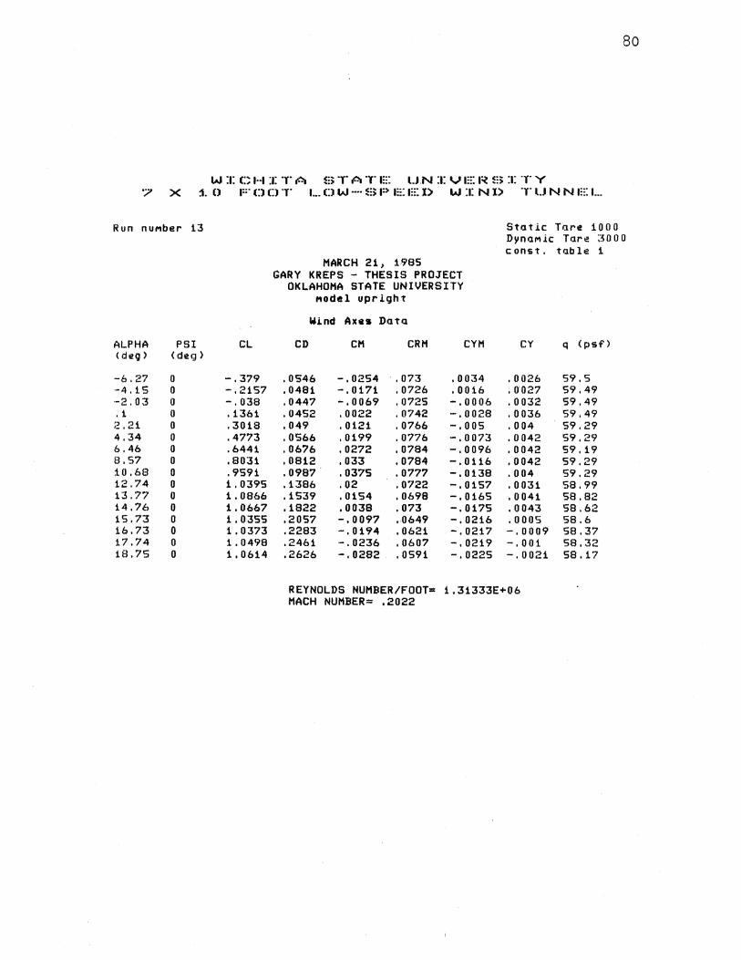
80
WICHITA STATE U.NIVERSITY '7 X ::1. 0 1::· 0 D T 1 ... 0 W ···· B P t::: EX> W :1: N X> T U N N 1::: 1...
Run nuMber 13 Statlc Tare 1000 DynaMic Tart:! ::so 0 0 c onst, table 1
MARCH 21 1 1985 GARY KREPS - THESIS PROJECT
OKLAHOMA STATE UNIVERSITY ,.,odel upright
W.i.nd Axes DatiJ
ALPHA PSI CL CD CH CRH CYM CY q (psf> < deg > < deg)
-6.27 0 -.379 '0546 -' 0254 '073 .0034 .0026 59.5 ·-4' 1 s 0 -.2157 '0481 -' 0171 .0726 .0016 .0027 59.49 ·-2' 03 0 -' 038 '0447 -.0069 '0725 -.0006 .0032 59.49 .1 0 .1361 '0452 '0022 .0742 -.0028 .0036 59.49 ;; '21 0 .3018 .049 .0121 '0766 -' oos .004 59.29 4.34 0 .4773 .0566 .0199 .0776 -.0073 .0042 59.29 6.46 0 .6441 '0676 .0272 .0784 -.0096 .0042 59.19 8.57 0 .8031 '0812 .033 .0784 -.0116 .0042 59.29 10.68 0 .9591 '0987 .0375 .0777 -.0138 .004 59.29 12.74 0 1.0395 '1386 .02 .0722 -. 0157 .0031 58.99 13.77 0 1.0866 '1539 .0154 .0698 -.0165 .0041 58.82 14.76 0 1.0667 '1822 .0038 . 073 -.0175 .0043 58.62 15.73 0 1.03SS .2057 -. 0097 .0649 -. 0216 .ooos 58.6 16.73 0 1.0373 .2283 -.0194 .0621 -.0217 -.0009 58.37 l. 7. 74 0 1.0498 .2461 -. 0236 .0607 -.0219 -.001 58.32 18.75 0 1.0614 .2626 -' 0282 .0591 -' 0225 -.0021 sa. 17
REYNOLDS NUMBER/FOOT= 1,31333E+06 MACH NUMBER= .2022

81
W :1: G H :1: T A !:;: T A T m: l.J N :1: VIE I~ !:3: :1: T Y 7 X ~0. FOOT LOW-SPEED WIND TUNNEL
Run nuMber 14 Static. Tare 1000 DynaMic Tare 3000 const. table 1
MARCH 21 1 1985 GARY KREPS - THESIS PROJECT
OKLAHOMA STATE UNIVERSITY Model upright
lUnd Axes Data
ALPHA PSI CL CD CM CRM CYM CY q <psf> <deg> < deg)
-6.26 0 -.363 . 0538 -' 0284 .0703 .0031 .0023 59.5 ·-4' 14 0 -.194 '0469 -. 0211 . 0672 .0012 .0026 59.59 -2.02 0 -. 0288 . 0439 -. 0143 .0655 -.0007 .0031 59.49 .11 0 .16 .0442 -. 0068 • 0638 -.0027 .0034 59.39 ;.~. 24 0 .3435 .049 .00()1 .0618 ·-.0046 .0036 59.29 4 '~~7 0 .5252 . 058 .006 .0605 -,0062 .0037 59.29 6. 4'7 0 .6972 .0704 '0114 .0585 -' 0078 .0033 59.29 8.61 0 .8681 • 0862 ,0167 .0565 -.0091 .003 ·59. 29 10.73 0 1.0257 .1058 .0202 .0538 -.0104 .01123 59.19 12.79 0 1.1166 .1491 -.0009 .0474 -. 0118 .0014 58.99 13.8;;~ 0 1.1582 .1657 -.0034 .0443 -. 0126 .0017 58.83 14.82 0 1.1516 .1943 -. 0175 ,049 -.0132 .0006 58.62 . 15.84 0 1.1877 .2133 -, 0239 .0516 -.0136 -. 0005 58.66 16.79 0 1; 1151 .243 -. 0399 . 0372 -.0161 -. 0027 58.39 17.8 0· 1.1301 .2635 -. 0456 .0348 -. 0162 -. 0 033 58.34 18.81 0 1.1436 .28 -.0491 .0302 -. 0162 -. 0 037 58.19
REYNOLDS NUMBER/FOOT= 1.30688E+06 MACH NUMBER= .2022
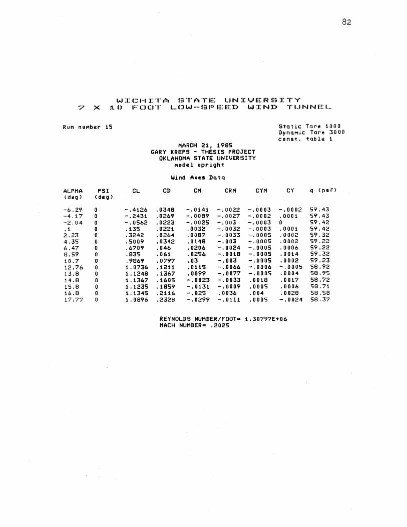
82
W :1: C H :1: T A S T A T a::: l.J N :a: V a::: a~ m :a: T Y "7 X ::1. 0 1::· 0 C) T 1. •• CJ W -·· s; P a::: 1::: l) W :1: N l) T l.J N N a::: 1...
Run nuMber iS Static Tare 1000 DynaMic Tare 3000 c:onst. table i
MARCH 21 1 1985 GARY KREPS - THESIS PROJECT
OKLAHOMA STATE UNIVERSITY Model upriQht
Wind Axes Data
ALPHA PSI CL CD CH CRM CYH CY q <psf'> < deg) ( deg)
-6.29 0 -.4126 '0348 -.0141 -.0022 -.0003 -.0002 59.43 -4' 17 0 -.2431 '0269 -.0089 -.0027 -.0002 .0001 59.43 -2.04 0 -. 0562 '0223 -. 0025 -.003 -.0003 0 59.42 .1 0 .135 .0221 .0032 -.0032 -' 0003 .0001 59.42 2.23 0 .3242 . 0264 ,0087 -,0033 -, 0 0 OS .0002 59.32 4.35 0 .5009 '0342 .0148 -.003 -.0005 .0002 59.22 6.47 0 .6'709 '046 '0206 -.0024 -.0005 .0006 59.22 8.59 0 .835 .061 '0256 -.0018 -.ooos .0014 59.32 10.7 0 .9869 . 0797 .03 -. 003 -.0005 .0002 59.23 12.76 0 1 '0'736 '1211 . 0115 -.0066 -.0006 -.ooos 58.92 l.3 .8 0 1.1248 '1367 .0099 -.0077 -.0005 .0004 S8.9S 14.8 0 1.1367 '1605 -' 0023 -.0033 .0018 .0017 58.72 1.5.8 0 1.123S '1859 -.0131 -,0009 .ooos .0006 58.71 16.8 0 1' 1345 .2116 -, 025 .0036 .004 .0028 SB.SB 17.77 0 1.0896 .2328 -' 0299 -.0111 .ooos -.0024 58.37
REYNOLDS NUMBER/FOOT= 1,30797E+06 MACH NUMBER= .2025

83
W :1: C H :1: T A ~;) T A T m: U N :t: V 1::: I~ ~:; :1: T Y '7 X j, 0 F 0 0 T 1 ... D W ···· m P E 1::: l) W :1: N l) T l.J N N 1::: 1...
Run nuMber 16 Stat .i.e Tr.u·e 1000 DynaMic Tare ;30 0 0 const. table j_
MARCH 21' 1985 GARY KREPS - THESIS PROJECT
OKLAHOMA STATE UNIVERSITY Model upr.i.ght
W.i.nd Axes Data
ALPHA PSI CL CD CH CRH CYM CY q <psf) (cteg) <deg)
-6.31 0 -.442 . 0385 -.0039 -.0017 -.0004 .0003 59.44 -4, i 11' 0 -.2699 . 0301 .0014 -.0022 -.0003 .0003 59.43 -2' 06 0 -.0886 '0254 .007 -.0024 -.0004 .0002 59.33 .07 0 .1017 . 0243 .0123 -.0026 -.ooo5 .0003 59.43 2 I 21. 0 .2927 .0274 .0175 -' 003 -.0006 ,0005 59.32 4' 3:3 0 .4706 . 0344 .0221 -.0032 -.0006 .0007 59.42 6.46 0 .6544 . 0459 . 0263 -.0029 -. 0006 .0012 59' 12 8.S8 0 .8209 . 0604 .0301 -.0033 -.0006 .0011 59.12 j_O. 69 0 .9753 . 0789 .0335 -.0033 -.000'7 .0004 59.03 12.72 0 1.0218 '1256 '0111 . 0011 -.001 .ooos 58.76 13.75 0 1.0557 .1464 .003 ,0006 -.0011 -,0004 58.71 14.78 0 1.096 .1633 -.0022 .001 -.0011 -.0008 58.55 1S.8t 0 1.1442 .1802 -.0045 .0024 -.0012 -.0014 58.58 16.75 0 1.0623 .2103 -. 0232 -.0108 -. 0006 -.0029 58.31 17.76 0 1.0785 .2302 -. 0276 -.0112 -. 0 0 03 -. 0029 58.26
REYNOLDS NUMBER/FOOT= 1.30079E+06 MACH NUMBER= .2023
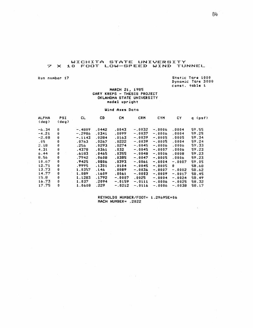
84
WZCHXTA STATE UNIVERSITY 7 X ~0 FOOT LOW-SPEED WIND TUNNEL
I~ un nuMber 17 Static Tare 1000 Dynaf''lic Tare 3000 const. tabla 1
MARCH 21, 1985 GARY KREPS - THESIS PROJECT
OKLAHOMA STATE UNIVERSITY "odel upr.ight
Wind Axes Data
AL.PHA PSI CL CD CM CRM CYM CY q <psf> < deg > < deg >
-6.34 0 -.4809 . 0442 .0043 -.0032 -.0006 .0004 S9.SS -4.21 0 -.2986 .0341 .0099 -.003? -.0006 .0004 S9.2S -2.08 0 -.1143 .0284 . 0163 -.0039 -.ooos .ooos 59.34 .OS 0 .0?63 .0267 . 0222 -.0039 -. 0005 .0004 59.24 2.18 0 .256 .0293 . 02?4 -.0045 -.0006 .0006 59.33 4.31 0 .4378 .0361 .032 -.0045 -,0007 .0006 59.23 6.44 0 .6183 .0465 .0355 -.0048 -.0006 .0008 59.23 8.56 0 .?942 .0608 .0385 -.004? -.ooos .0006 59.23 10.67 0 .9425 .0806 .0393 -.0061 -.0004 -.0007 S9. OS 12.71 0 .9995 .1301 .0104 -.0045 -.ooos 0 58.68 13.73 0 1.0357 .146 ,0089 -.0036 -.0007 -.0002 58.62 14.77 0 1.089 .160.9 .0061 -.0003 -.0009 -.001? 58.45 15.8 0 1.1283 .1792 -.000? .0025 -.0004 -.0024 58.49 16.73 0 1.037 .2094 -. 0159 -.0111 -.0006 -.0025 58.32 17.75 0 1.0608 .229 -.0212 -.0116 -.0006 -.0038 sa .11
REYNOLDS NUMBER/FOOT= 1.2969SE+06 MACH NUMBER= .2022
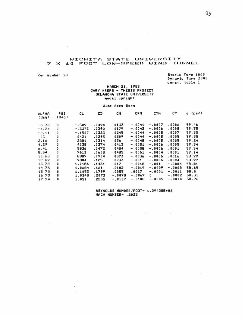
85
W~CHITA STATE UN~VERS~TY 7 X ~0 FOOT LOW-SPEED WIND TUNNEL
Run nuMber 18 Static Tare 1000 DynaMic Tare ~5000
const. table 1 MARCH 21, 1985
GARY KREPS - THESIS PROJECT OKLAHOMA STATE UNIVERSITY
l'lodel upright
Wind Axes Data
ALPHA PSI CL CD CH CRH CYM CY q <psf'> < deg > <deg>
-6.36 0 -.509 . 0494 .0133 -.0041 -.0007 .0006 59.46 -4.24 0 -.3373 . 0392 .0179 -.0042 -.0006 .0008 59.55 -2.11 0 -.1507 . 0323 .0245 -. 0044 -.ooos .0007 S9.3S .03 0 .0421 . 0295 .0309 -.0044 -.ooos .ooos S9,3S 2.16 0 .2281 . 0314 .036 -.0048 -.ooos .ooos 59.24 4 .2·~ 0 .4038 . 0374 .0413 -.0051 -.0006 .0005 59,34 6.41 0 .5836 .0472 .0454 -.oosa -.0006 .0001 59.34 8.54 0 .7613 .0608 . 0485 -.0061 -.0004 .0001 59.14 10.63 0 .8889 . 0904 .03'73 -.0036 -.0006 .0016 58.99 1.2 .69 0 .9804 .125 .0233 -.001 -.0006 .0004 58.97 13.72 0 1.0186 .1431 .017 -.0018 -. 001 -.0004 58.81 14.76 0 1.0684 .161 .0102 -.0019 -.0009 -.0008 58.65 15.·78 0 1.1053 .1799 .ooss .0017 -,0001 -.0011 58.5 16.73 0 1.0348 .2073 -. 0098 -.0067 0 -. 0002 58.31 17.74 0 1.051 .2255 -. 0137 -.0108 -.ooos -.0014 58.26
REYNOLDS NUMBER/FOOT= 1.29428E+06 MACH NUMBER= .2023
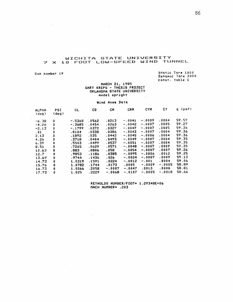
86
W :J: C H :1: T A ~::; T AT E l.J N :a: V a::: a~ S :t: T Y '7 X :1. () F D Cl T 1 ... CJ W ···· ~::;; P 1::: EX> W :1: N l> T U N N E 1...
I~ un nuMber 19 ~tatlc Tr.~.re 1000 DynaMic Tare ;:~ooo
const. table 1 MARCH 21 1 1985
GARY KREPS - THESIS PROJECT OKLAHOMA STATE UNIVERSITY
Model upright
W.Lnd Axes Data
ALPHA PSI CL CD CM CRH CYM CY q <psf> < deg) (deg>
-6.38 0 -.5368 '0562 .0213 -' 0041 -.0009 .0004 59,57 ·~4 '26 0 -.3685 .0454 '0263 -.0042 ,-.0007 .ooos 59.27 -;~' 13 0 -' 1799 .0372 .0327 -.0047 -.0007 .ooos 59.36 .01 0 .0104 '0338 .0386 -.0043 -.0007 .0004 59.36 2' 13 0 '1892 '035 .0442 -' 0045 -.0006 ,0004 59,36 4.26 0 .3718 '0404 .0493 -.0049 -.0007 .0004 S9.3S 6.39 0 .5503 '0499 ,0537 -.0051 -.0007 .0004 S9.3S 8.51 0 .7265 '0629 ,0571 -' 0048 -.0007 .0009 S9.3S 10,63 0 .883 '0806 .058 -,0054 -.0007 .0007 59.26 12.7 0 .9853 '1186 '0385 -. 0095 -.0006 .0012 59.25 13.69 0 .9744 '1436 .026 -.0024 -.0007 .0009 S9 .13 14.73 0 1.0319 '1591 .0224 -.0012 -.001 .0004 59' 06 15.76 0 1.0782 '1744 .0173 .0005 -.0009 -.ooo5 58.89 16.73 0 1.0266 .2058 -.0007 -.0047 .0013 .0008 58.81 17.73 0 1.025 .2229 -' 0068 -.0107 -.ooos -.0018 58.66
REYNOLDS NUMBER/FOOT= 1.29348E+06 MACH NUMBER• .203
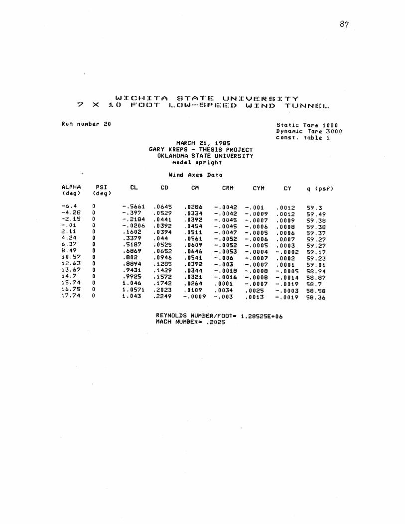
87
W :1: C H :1: T A ~:; T A T m: U N :1: V 1::: I~ B :1: T Y '7 X :1. () F 0 0 T L D W ···· B 1:) E 1::: X> W :1: N l) T l.J N N 1::: 1. ••
Run nuMber 20 Stat i.e Tr.H·e 1000 DynaMic Tare ~~000 c onst. ttJble 1
MARCH 21 1 1985 GARY KREPS - THESIS PROJECT
OKLAHOMA STATE UNIVERSITY MOdel upright
Wind Axes Data
ALPHA PSI CL CD CM CRM CYM CY q <psf> < deg > <deg)
-6.4 0 -.5661 . 0645 • 0286 -.0042 -.001 .0012 59.3 -4.28 0 -.397 . 0529 . 0334 -.0042 -.0009 .0012 59.49 ... 2. 15 0 -.2184 '0441 .0392 -.0045 -.0007 .0009 59.38 -' 01 0 -.0206 .0392 . 0454 -.0045 -.0006 .0008 59.38 ;2. i1 0 .1602 '0394 . 0511 -.0047 -.0005 ,0006 59.37 4.24 0 .3379 '044 .0561 -.0052 -.0006 '0,007 59.27 6.37 0 .5187 .0525 .0609 -.0052 -.ooos .0003 59.27 8.49 0 .6869 '0652 .0646 -.0053 -.0004 -.0002 59' 17 10.57 0 .802 '0946 .0541 -.006 -.0007 .0002 59.23 12.63 0 .8894 '1285 .0392 -.003 -.0007 .0001 59.01 13.67 0 .9431 '1429 .0344 -.0018 -. 0008 -.ooos 58.94 14.7 0 .9925 .1572 .0321 -.0016 -.0008 -' 0014 58.87 15.74 0 1.046 .1742 .0264 .0001 -.0007 -.0019 58.7 16.75 0 1.0571 .2023 .0109 .0034 .0025 -.0003 sa.sa 17.74 0 1.043 .2249 -' 0009 -.003 .0013 -.0019 58.36
REYNOLDS NUMBER/FOOT= 1.28S2SE+06 MACH NUMBER= .2025
APPENDIX C
WIND TUNNEL COEFFICIENT PLOTS
88
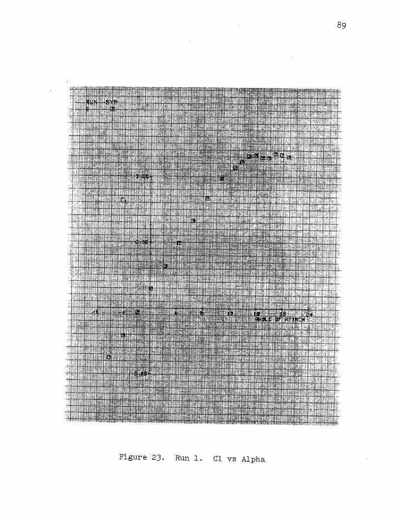
,: li ::, I!
_d_ii i
'i: ;:::
' 1!11 . ,
i ;:1· ":''I
. I:
' 'I
'' ! 11 I I.'
:·:; 'I
:. ill I I! lj
I i
I
.!1 i
1: I
i I j I
Figure 2J.
' !i
. I
tl' I '• ·,I Itt li 'I
" iii
ll;
I 'II
;;:
'· I
'1.'
'!
••• .. ' . .L:
I I,
. i , · Ill ~ I ·
llffU
•• _ II•, •~!ilfffi,~,:~M-::·H.i u+i1 ·H'·+f·~ H:,
u~ i:
,: !
~·
~ I •
, lUI , I
Run 1. Cl vs Alpha
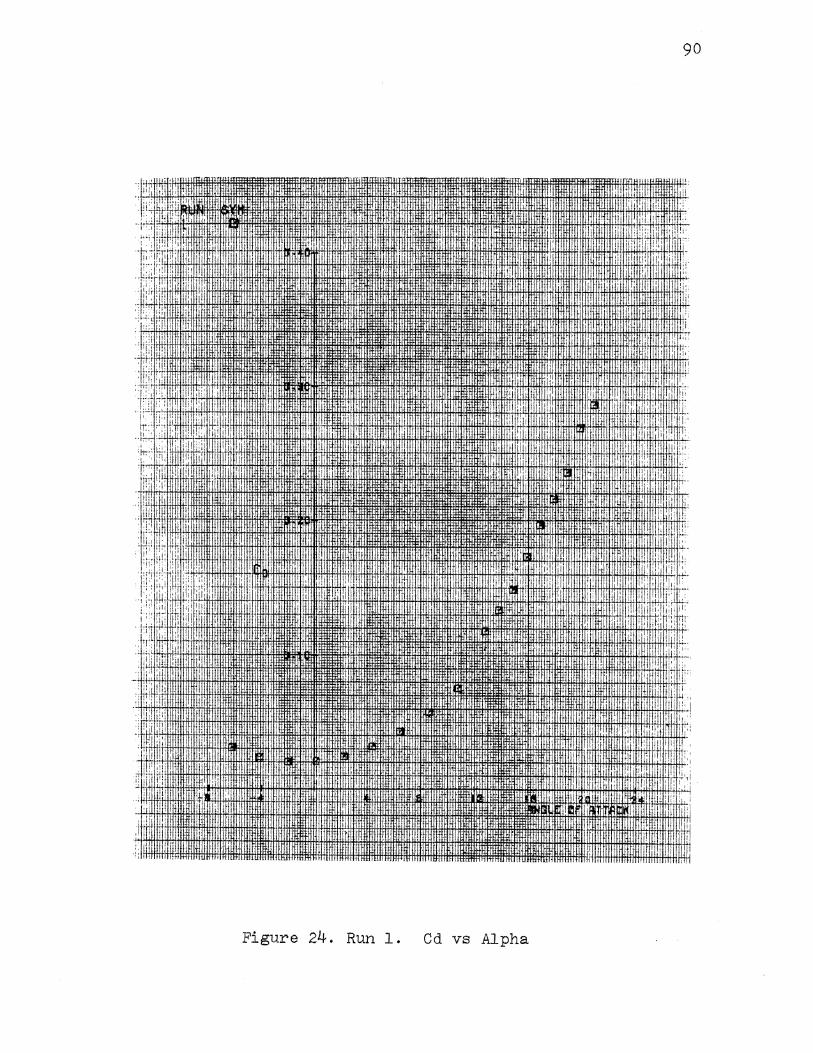
I:! Iii' '
Jt: "I ::u ·r ' .. i. '' !I' I. '. i!!!
·'' r;;: :; tr; :!1 ' '
. i;i ill,
:: : ~+·
I I'
.: I . •,
: i, :[':"11 "!":! : I 1:;1 I
I' I~! ; I' [I ' IJU ·~·;i
1:· :i I· iii I,: ··~
I ' i i ~ i . ·,I :' ' fu[ i' I 1'"" I:: j !
! T
'l1 ,,,
" ;I!!
u " '•I
'! li I
·!:
I lj .·a-.""""""""'
·I
• • •• II'
I I f ;r T 11 ·tt
[I
I
I! IIi : I
Figure 24. Run 1. Cd vs Alpha
,t,l
r·:
90
':1:.: ·.'.[!1
1' U
I' I
I [i
IIi j.,:
l ~ '·1', I !:
~I! u ! !I.'
II
j, I I.
·I i'
lfl ,[' 1r:
1!1 ~~-I'
'I, ti.,!
I. ! !' .l i
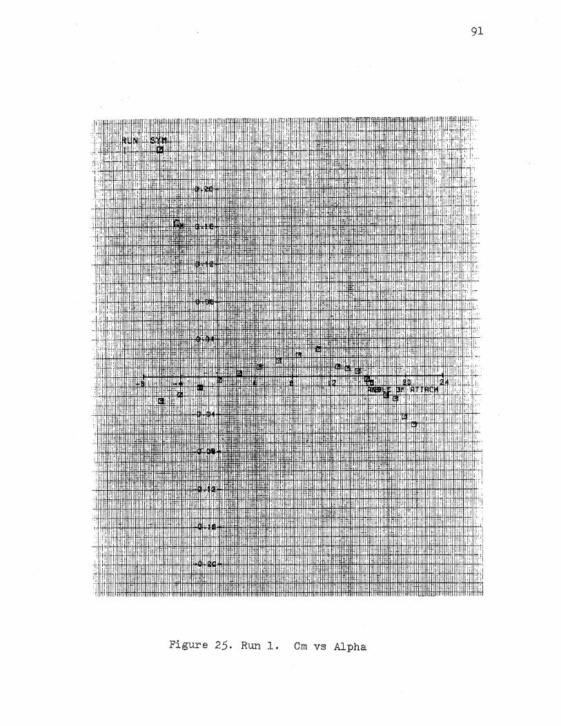
91
... . a·· 1•
1
,
1··1···1
1
•• mm·
• 'I
·:
: ,1: ilt\liJ[li!J I •
' 1 liiiTIWlli I !
,I
I I· :: !1!\ I
jo I
' ' :;, j,
' ;I• fl' I, :lii/i'
I ·:.W,· I•.
·IH1
11111·r:oo::. ~:~1rr~rHi+H+.fi:Hi~ .fM#I!t:ttHttttilttt~'H:~' =~ ~lW14J4fmlif+l. ·I tfli:iJAA!IW,.Iij~H:Wf~~W:HJi~filffli~ :'1 iW,j, ,l ~lrtl"i'ft !,tfr!'t~ l. c~ i~c ·
. Pli I. : !!'• ' !~· I•' .
1il .ll!l !( II.
il• ! I :i ..
I'' !i ,!
'~jli ' lii ; ;;~~ ............... lu~~~-·~ :1.1HH·H ......... 1
' j;.J jl'
; I ,, I ''] cj'~-........ ~----~-----j - I
:!• I ; )
~:IIII~·IIIIIIIIIIIIIIIII'B'u I , .I
Figure 25. Run 1. Cm vs Alpha
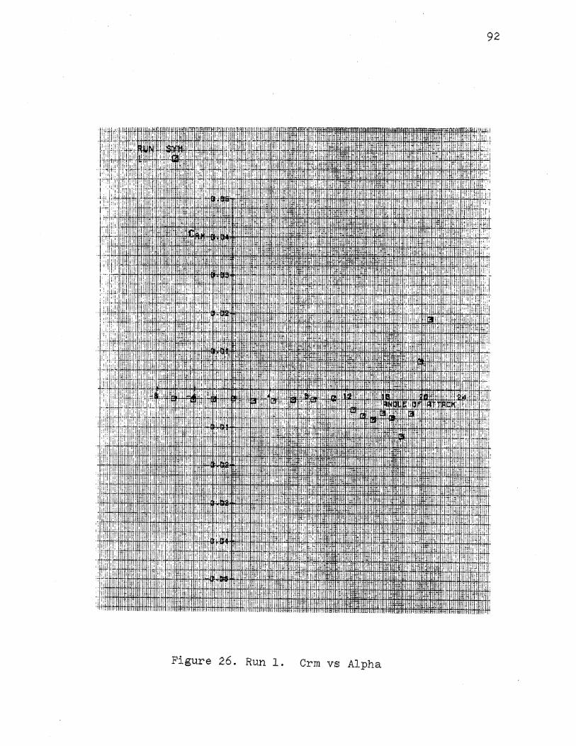
92
iliil ' liJ ' 1ill!IDJ ' 1i1JJL' I[· lJ:!l Jll;
I' > ii. J . ,,; ;c: I ::J..
d
:' !•·
Ill, ::[:1 'I' '
,, ;: i
I i! !ij_
:i'i :,~r~ : :j
:1 :',''
'lL
;wt I ~ :
I I 1;, ,: l !: iJi• ! til'
~ " ' '' . I II !I Wl
:;: !I : I
·'I I j
•!J .,
·I· .,I,. I, .d I ,f;· !1'1 ''i' t1l li 1 1 1 i'! ii··
i · : : 1 f1fh· Iii i i Wrffifim fltniWll-rtw~ ~till!ffill1~1m~tijWril 1~1rml~Gtrrmmn~inlmiTmnnffi[mmJ!t~mtltttllfliDilltlli!tlli11rulllli1!lllillill : l~i~,li:f+ n~;~:'Hi: :411
.llt'r·t :+H,·~·H Wiu~~.·rf~MffHiiffiff+HttfffiH+ittltttltltffiHtllitltltwrijtf!lrnm·~~ I,
i I 1:;: !I . !· i ' : I
.. n: pi: ' f:i ill !
tj!i ,!
II I 'I;' .II· irr :I I
I Gl ' 'I'
I ~. I I i
, I
:i I! I
Figure 26. Run 1. Crm vs Alpha
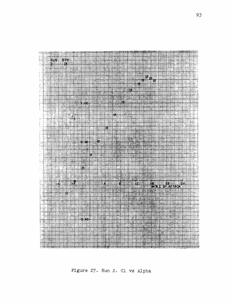
93
''·:, ,I
,I
' ' l!i ~~~ I jf! .!!'
. II I }ii
~Uiilll '
II'
::j I. I I
I 'l TIHII!!I, ,! ll:_
1: II ,, ~.· 1: 'I
1, ! I :if!·' ' I
: I ·' ! :.1 fh'
I'
I ·,j:· ::: i i !
I' I :;; I '
''· I ;,
' ~; I 1''1
.I :I i ,: li' I
,':.
· unm
Figure 27. Run 2. Cl vs Alpha
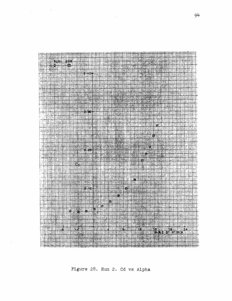
; !
li I
I' I : ' . ;i I'
!:i. I' 1
,I '[ji I II I
•i ill
,,
I
I i'
I I
!:, ,, j( .·
I
:
! ' ' '
I
I'
li I
!'
Jli!Ull.i 1HH ,. I'
'I. [I ,,
i! : I'
"" ·: I :·; ::;: '! i f tii'
'I
il i I I Ill
!·
a:·
., '
I '
I;
II
I 1111' RTII IHI1!1 •m nn ,, I ' ; ~
I ,1,1 ii' 1' :' 1;-I j i'i' 'I:
; i I 'i_;
:I' ,. 1: ! !i
I
·'I I ·;·! I ! !I I I
' ~ I I :TFLEI.tt il I ' li· ! I I' I [
' I 1': lj'
I' : I" !I
I ! I ill
I I I 1. ' : i:! ' I I, I
I ' ! I 'li;,
•II !I I[ I
il' )
1.1 ,, ;: ti'r
!-i. 'II!Jj,: il !y i(!' '1W: '
::;1· .. ,,
:I i il;! IUt ,, II
1.: I I ;i : 1:1:; :! !il :'•
il!llmt
' I ii i 1[: Ji:l ' !! . I ,.
i !li I. I
I' I il' I
'I "' I I 'i: ,, ,.
I i•j' ,.:; i i '
I ,I ,I i'.J!
II i.
I !. I; il.L'i
: ' I [!! :. il u'
l:l.
'I' ,., i I
ill j:
!'
jl I
I
l1 ·'. ], IIHIIIIHIIHIII! HI tNil
:lltlettflllltl llllll'lc.nnmu•
1111t1 u!iUU~UHflfiiiiHIIillllrmuwHJHlllliJ:· tlltnurrmmm , lilttl . ltlltt•lllll·lllll·!l!;>
Figure 28. Run 2. Cd vs Alpha
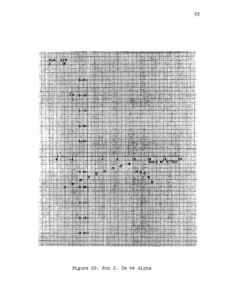
95
,f:\i!j ,ji!i •I I·! ·I· I '!i 1 ' 'il iri]' I;'
I ;.!, ,, :f
I·:
'ii
~'1;::1 { I i ~ ~ ! ~
~~ : ! : : ~ i i i ·I I r 1! :.if~ '
1:, .I I' .:·
ill. li . i I I ,' ii "' :1 1: . ; II ti: It I .I'
,, ' li·
lr' :', ·iT:· 'II I i I,
:1 l:J I'
: II :• 11:1 jl•
: ·II' II
: i i·
I· ::•, ,I
,, ii ,I ';,, ",:
l:i I I : ·i· I I :i ·I ~· I li 1:: .11 1 I ' ii : ~ ~ I
:1+1::1 { ''I I! i
' ] ~ ' •• I ' I ' : ; : :I .. : i I!; I I,
''·
!! I I !II I
i i; i f'!l . I i I i .,1 ,I
,,1' ::: i 'I I I :
.. :: .,, IU: I I. I, il I I !1 1[ i:i!
II
I; I· 'i r ''I t: .. ,,~ ... ·~ I !rl
,' ·:.J" I :.i ~~ ..
'. "!': i' • ~ i i
H!;n I
·• II' , '':ill
'I :' 1·11 ll
fi tj +~~~f! !i I ji ,
1:] i : f~~-. _li ' I· Lli 1;;
. !i ;!'!!I! ' i I ,, I I; , 11r:
'i,: .. ' "f! ::' ,,:: :·!, II I I• '
!I ,lj, I lj.l !. I
•.• :i': :il; iii: ., I ! !li I i· ::: ,·,:·; j I !q: I 'li !If
I IIHEU:l· II
.. ' I ' UtffiF ilr lit ,i
' " u.mt" I · ri :j .I ,, " .. ::1 ! !l ' I
,ll! •: '
II.
i' I II : ~! :.:: :
: ! \il ,, 'I,
' : t;jl "i i r: I H! ., ,I 'I : II I• I I
~::,H!nr:! 1 l! Ll! I I
~~ ,;tl 1 r. " " I
;i;l ::; I' I ' I' I;' I: iii :!;: :;:. I
i I I :I
iir :: Ill!'
f!i' '· I !;
Figure 29. Run 2. Cm vs Alpha
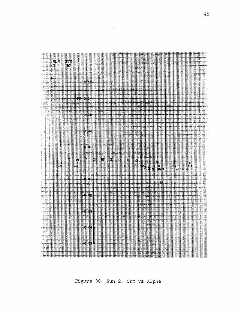
'l I li I .I ,1'1' 1 1 ; ';''"'! 1hlmlt+iHiH
11, tt!ftl1tt!1+ H+tfl:tt!I+!H1flii+!H+t4ti:lffl-i,+ 1i t+,H +.fl#!+i+H. ,t,H :H+ftH+Hj+!+ftH+Itl+ttH, 1-11',. 1+1 J.t.l·lfifl.lf#fi'EH'I:I fHtfftiH+Itl1itftttft!i*Hftffff!Ht!Hitlittlit+itiHfl+!cH'tc
:.~
Figure 30. Run 2. Orm vs Alpha

97
!1iil' :r I Iii ! : ~ I : ,i " .il· I,
ii Hrr~·. 'li . I I,
I I :£:' I' .1, 'I.
·:tli li:i! ... ii 'I' I:: li;i I· 'I: li' ii :•
·i ii '.:it, 'I I !1 1•!, .:1 II i I I· i
;;
li I II !I .!! ,,
I 'I I·
Ill ·I I i
''tt I : ·:
I 1':11 1llc
II. ':
I I .t h· : : ..
i) I I• ,. '
I ' •i I
; I
lrj I j ! ~
Ill' :I I' i 1': ~ q I It' I•. rr·l
ti i i tj' ·I
i ~ I I
I
,II~. ,,.
1\ I :I:. ' I iii :i'; ! I:):. I '
i; ! ,,
I I ; I
i ,,
I: I :!i , I ''I I I' li! ·! 1 ' I I I
i til :
!I ' I i ' "' !I;
II! i
,: ill ; ~ : d ,,
' 'i
·i: I
I ! ' ~ i I "
" :: i iq I I !! II :
I I
:I II I 11:1
li J.l.; !i
' : ,,,
' !t 1: i!l :i! t· ~ ~ I 1. ir'
' I :!1 !II 'i·l i!'
I I ! ,, ·>'.1 ' ·I~ ::.
:: ii ji: I 1::!
.I J . ·r:• ,,:
!'• lit 1: "i'
"' ,;: : i ltl'
' •I :r ' I I
:t IIIII l t:l''
Figure 31. Run J. Cl vs Alpha
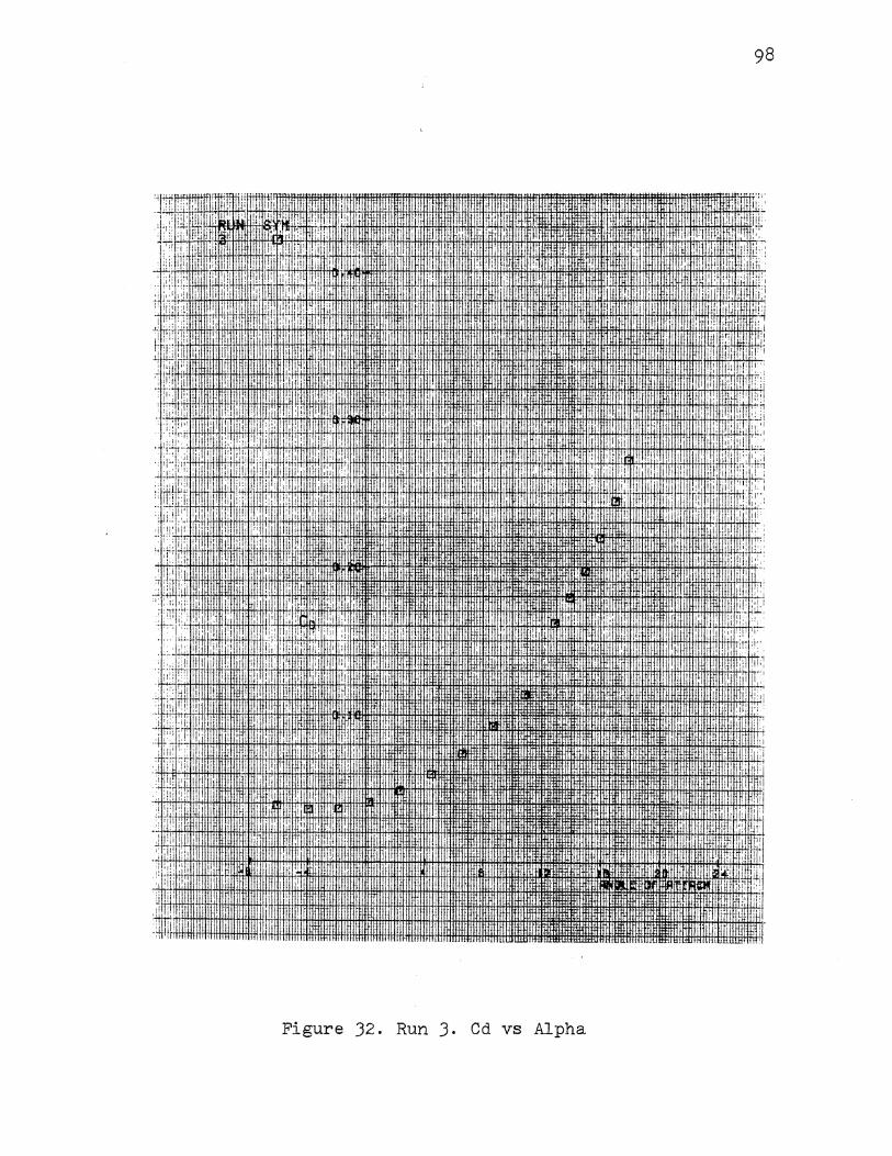
1,, II ,1
i 11 I
'[:t il
·I
98
. I
Figure J2. Run J. Cd vs Alpha

99
Figure JJ. Run J. Cm vs Alpha
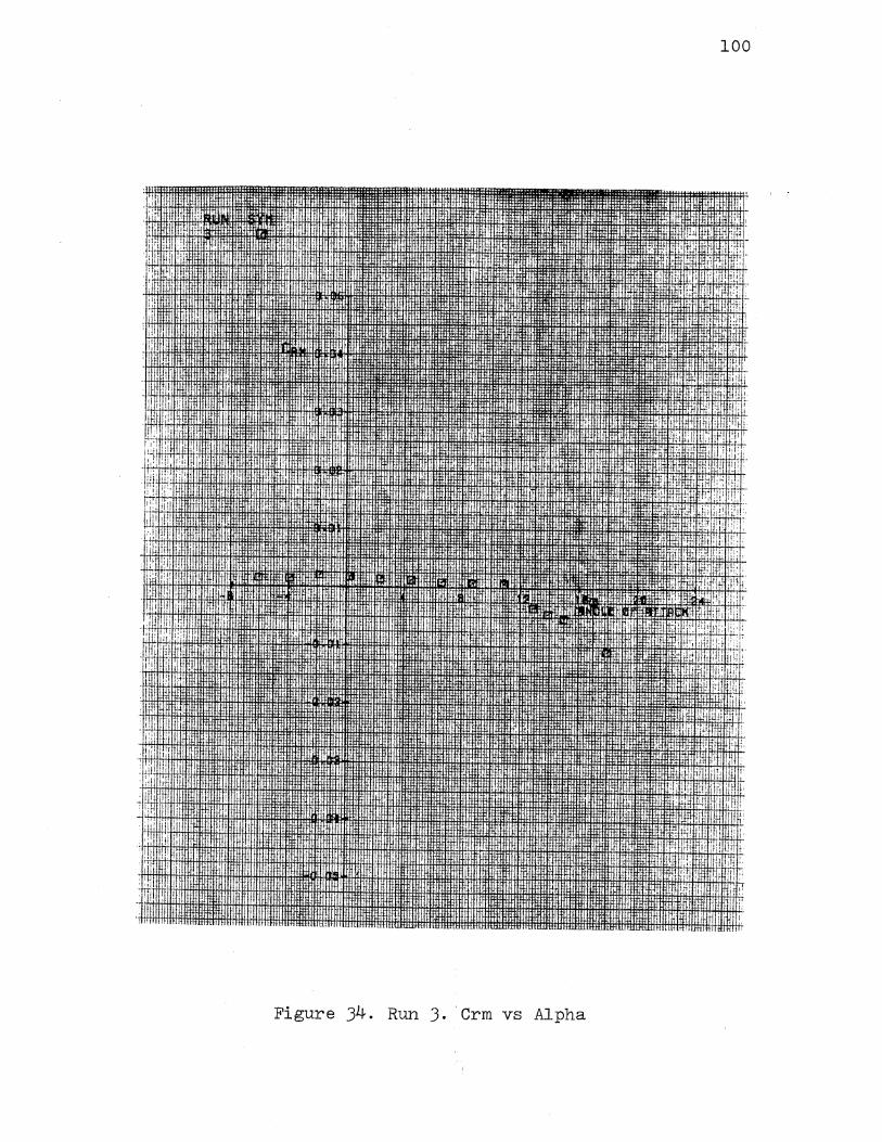
100
Figure 34. Run J. · Crm vs Alpha
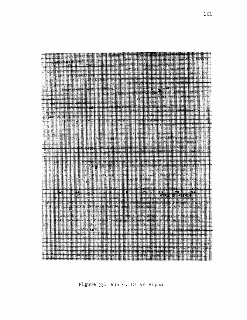
101
Figure 35. Run 4. Cl vs Alpha
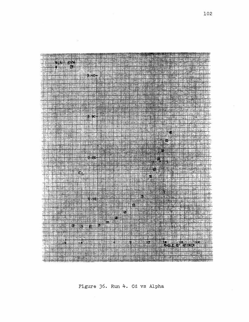
•,, ....... . ·,,' i 1!1 t1tr!tll.Hitlll1
J.lll HH+J.Il!ii+!+I-H+IfHH+I+~I
1-'
I.
I 1.1
I , q ' I I ~ I
I'' ij,: I :::I
rl
·,,I ·"' " '
'1, i·lll i'
''' r;·
·: i:!: 11
'
·i: d· I' · :: ··'
,, I'
ltul!Ut
j !liHif1illf§tffHhtlttl -nw~ HIJltf!ttffHumm ''i llnrii:Hmunrrlffilmlm mmrnnllflfl,
:•M llllliilll'lllllllfltUIIIll IJJt1Ht111Jr JUJil11iHmmm.~·
U!itltl llltl
Figure J6. Run 4. Cd vs Alpha
102
. I j : ~
'!' :i "' t!:" '' ll' .. ·
D
ilt .,;
,,, · .. ~~
I I
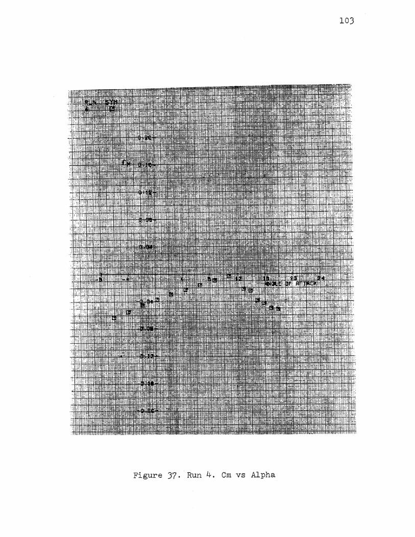
103
Figure 37. Run 4. Cm vs Alpha
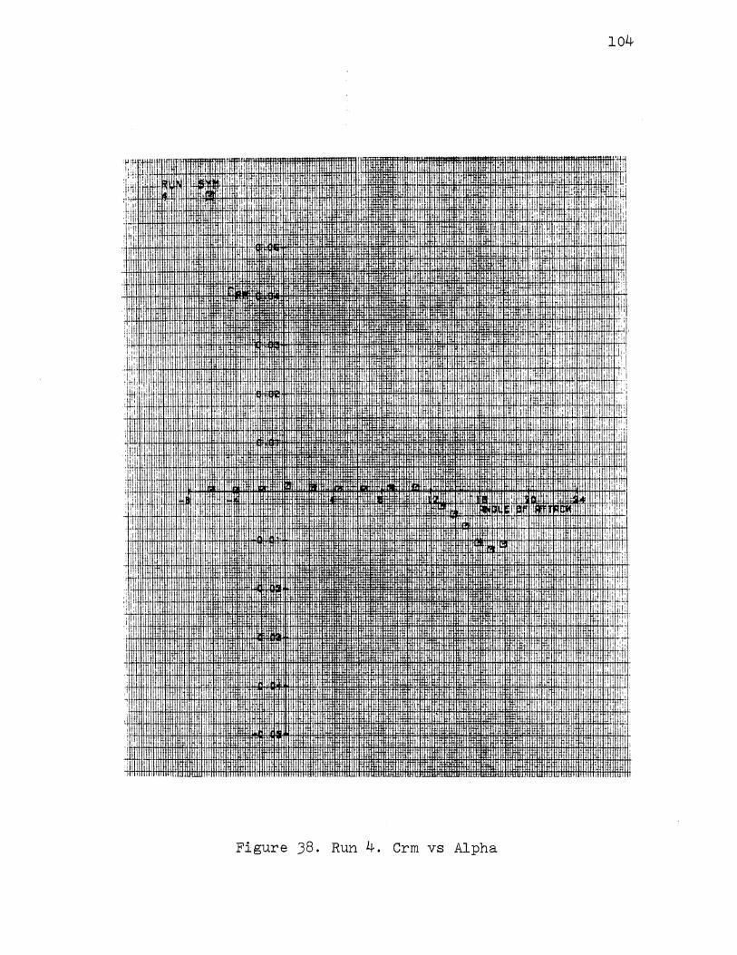
, I
·,i
' I
:I ,, I 'I
I! 'i i'
I
I.:
I
:
I i I
104
'I
~·
:1li
II:
, i ~ I I
·' '· 'I': I I I ,:I 1:: •i'
1! ! !i,
I
:~~m;rnm~~~--.·· .... • .... ~~~=~ 11
_,~ffiltHJBifLHI.IilltJI !1111111111111• ltllJIII "" · ....... ltttttllllttl.tiiiJit.ll . •. . J.ll . .Jftt!ll'mf~Hit4jtlt!JilfJ,W[HHJH:m+fJl.Hl:j.JOOf:J#l1~j.jj.J.l.l
Figure J8. Run 4. Crm vs Alpha
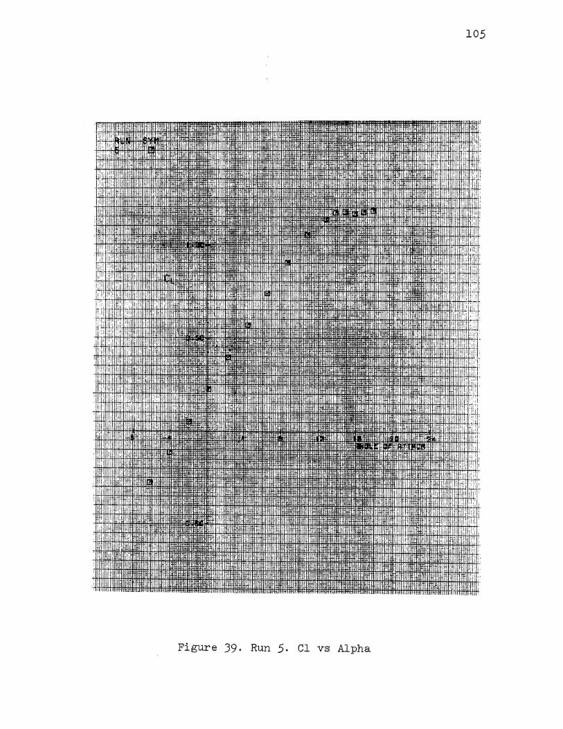
105
; I
'ji
. ! .
Figure 39. Run 5. Cl vs Alpha
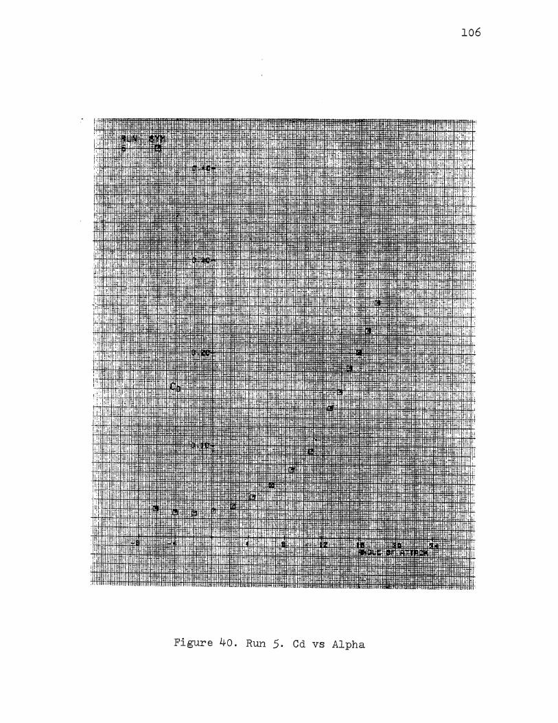
106
!':
' 'I
' I
Figure 40. Run 5. Cd vs Alpha
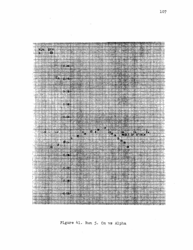
107
:>rTO:UllfiW
: ! :i\li!IIHTI ll!llllfll!i!IIHitllfiHfli!Utl£1UHWll 1m Hlflli!llHi!Jli!illtfltfH. 111tt rtrtt :mmu rtfm-1m itwfUI!J!fftH IIITHITflll! rnmnmlllll. . · ~ . ! II '
i "i
. I
. fttltiti.l
;,j [!-~ : I Htlit'!!ltHtrftlttttml1t:ffi
···: ·I"'. \f.!: i; 1
1 !!: I 1
-1\tl:t:W
il rucurtrrJIIIrliJI/1111 I' [I
'I" Iii
I
I•'
r:!
·i :. I
.;.!.' I ' I' jl
,, I
il+i>tli+flt+H+Il+H+i+H:Hith >'thffi:ttilt+ Htmffltl+ltffifH+ltlmH-11ffittttHltH+H' I~, 1rtmtttt111itiffirttl .~ttrtiiiitttittfttttltliiiffit~tftlttltttttlmtttttt1 H+!+!+++H++tfti-i :, : f~ l!:
:~ :•1 :tl
. ·:: ·::
;..;
j ·!' j'":l
I,
>I
i 'Jr
I I,
1.1 1', I
I, 1111
'I: I I ·;I i
I I! I It
I I
(
!
.. I
nu
IIHifll . I
Hmi:Uil 1
I I
• • tn\!1\1 lll\011 llllllll.llll ..... Uttti!UJ
Figure 41. Run 5. Cm vs Alpha
:'1 J• 'II
I :.!! l~ :It,
. i
II
iii:. ~~
p ii' ,!: li lrl :~!
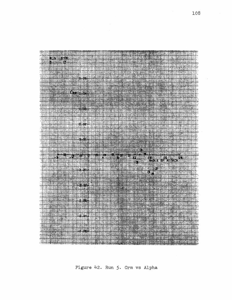
108
Figure 42. Run 5. Crm vs Alpha

t.l
!j I' ,,jl
:.:·
:~ It ' u i I ' i 1'1
i I
:1 I
1111 "" 1111 '""'
',I
I!IIHII
J!"ll 111'1. "'"''
Figure 4J. Run 6. Cl vs Alpha
109
! I!
ill
Lu!J "' '
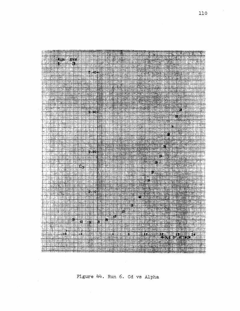
:I w . l • I
,'1'\
; I i j I ~
. . : ';:' . :1:,
1!' r:rt! ', ;r; l!' '
II' I
. i'i
I L
'i' J
':·I
II
I
' '
' . Ji I 'i
I
I'
I
...
:!1···~.. I jri: IL1i
ll·i! ~ .. r.
;;:.1 lll'Hlll . .
'~' :11 I il I pi, 1
i ·I,
'i!
·I I
I,
J. . I
. I ,
1:
! li
I! 'I ' ,,
I' ,.
., I
Figure 44. Run 6. Cd vs Alpha
110
':1
I •
I): I
lffi!
. ' 1_1.
I,
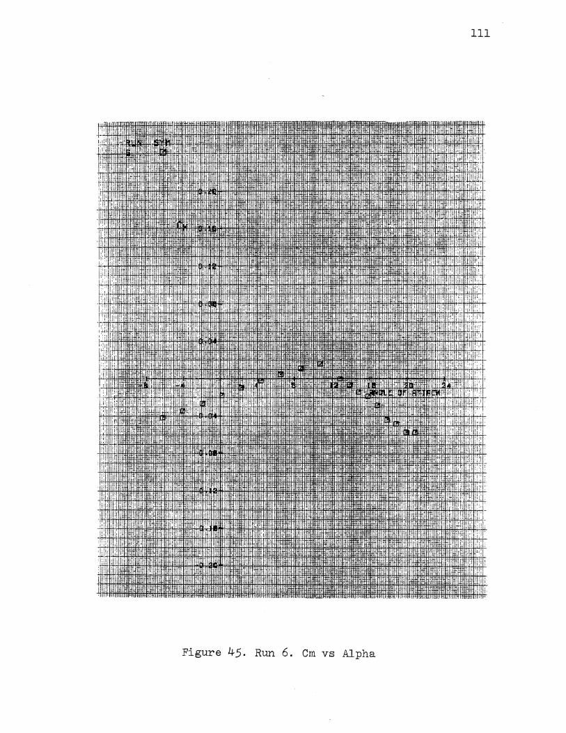
! :: I I'""'""'"'"' : '!
', [,jj '"'"'"""'
.II ~ I -\ ',,'
,;!: :I •:!: II'
,:: i'i: I ' I
' ::: 'I'
\.: ! I ! :; ';
:~i ; I I
i i
I ;,· 'i I
I: Iii I ll I!' ,, '
. r
' 'i
om:
I! 'I
... I I
'IIi I f·'j
Hill I
IJff!JH IUUJII
'i I
~-i I
I ! II
lrU.J.(\:1
•
··nm-wt.
,·,~. -~
ltmiii ~li:JJ-rt'
I:
•
Figure 45. Run 6. Cm vs Alpha
111
; I !l1
t!:
dU" I !E
'' ' ' ' lill , r:;:
'I I i':i
I ' ,, 'ij
'I U: ,:,:
:,1
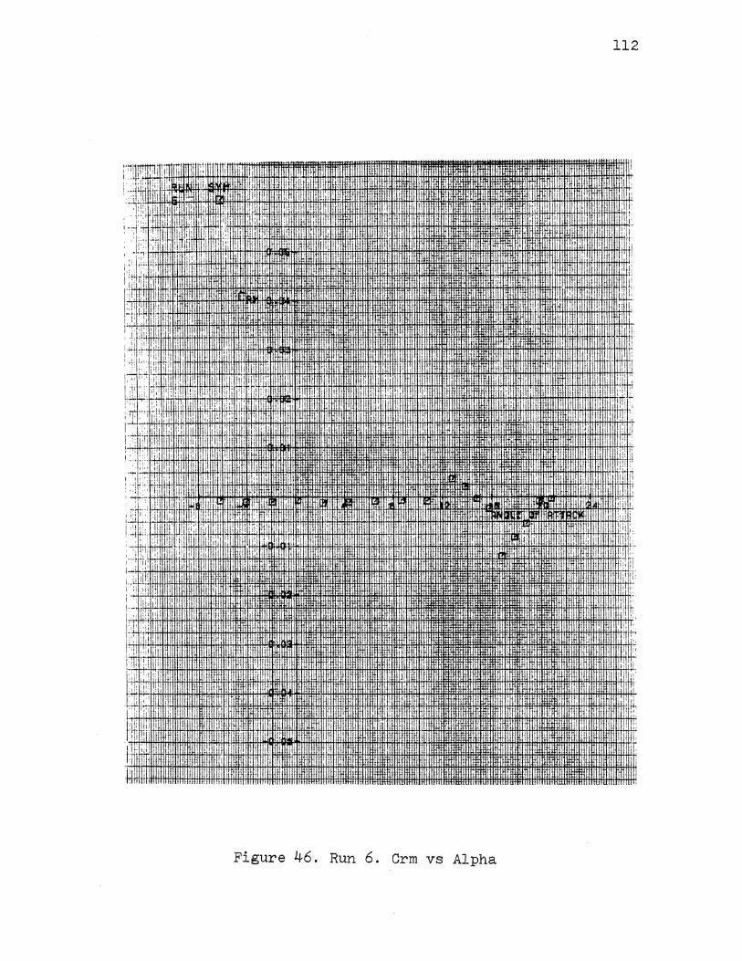
''""'*'"""'·11•,-rtrf'l :
1: II ill li
'· .... ,, ! ·:: ':'
. 1 ~ :
1;1:1,;
! ill:'
' ,•
I 'tL
, ! Iii
,, : i•l.
I::: il: I
. ~~;I I j'!
I l: 'i
.I.
. i I
, 'I! i JJ i!·! f fiflt4®i+ltJW!JW-J.i.i.!+OO!f!;lfili'tH11.tlhlfl*HtlilfffittH+tl1~ttli!tltffiH:HitlMtlllltllittffl:ltlffiiffi '•ti ,'
1 H! iliHll mmm ltl1ill!l11 ·+t!i.
1 '+II;!; AAIIIJIIIH+I#l+lllilll+Htl:I!I+HiLfl+l+l+ttHt++m+H+!H+ItlitlttH Im!tf~flt!Iffilffffitltl-fii-Ht1 flil 1aiHtlllntiHlfl: I! IHIIIH ffiT nlfR'!lll ltliltltH.
Figure 46. Run 6. Crm vs Alpha
I i
112
II II
T i:
II'
,.I
ti l!
I I
l!i
.IJ.: I
i! ]I
Ji l!i
' I, . I IL : i',
I h I Iii I'
i'l. jj
!\: I li I
!h.!, i'J ,, II,
1', I•·
I' 11
:j;lh ! II·
"· il
,. II
'tit il
UJj Ill!
I
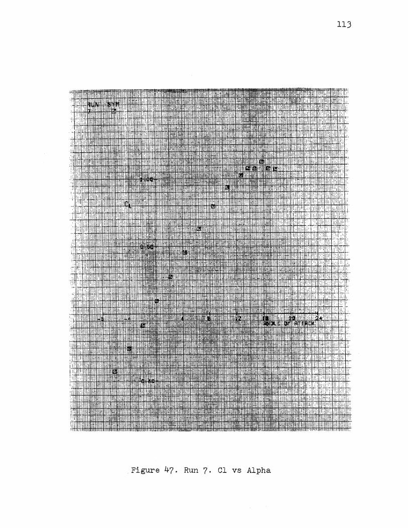
,1. rmm1·
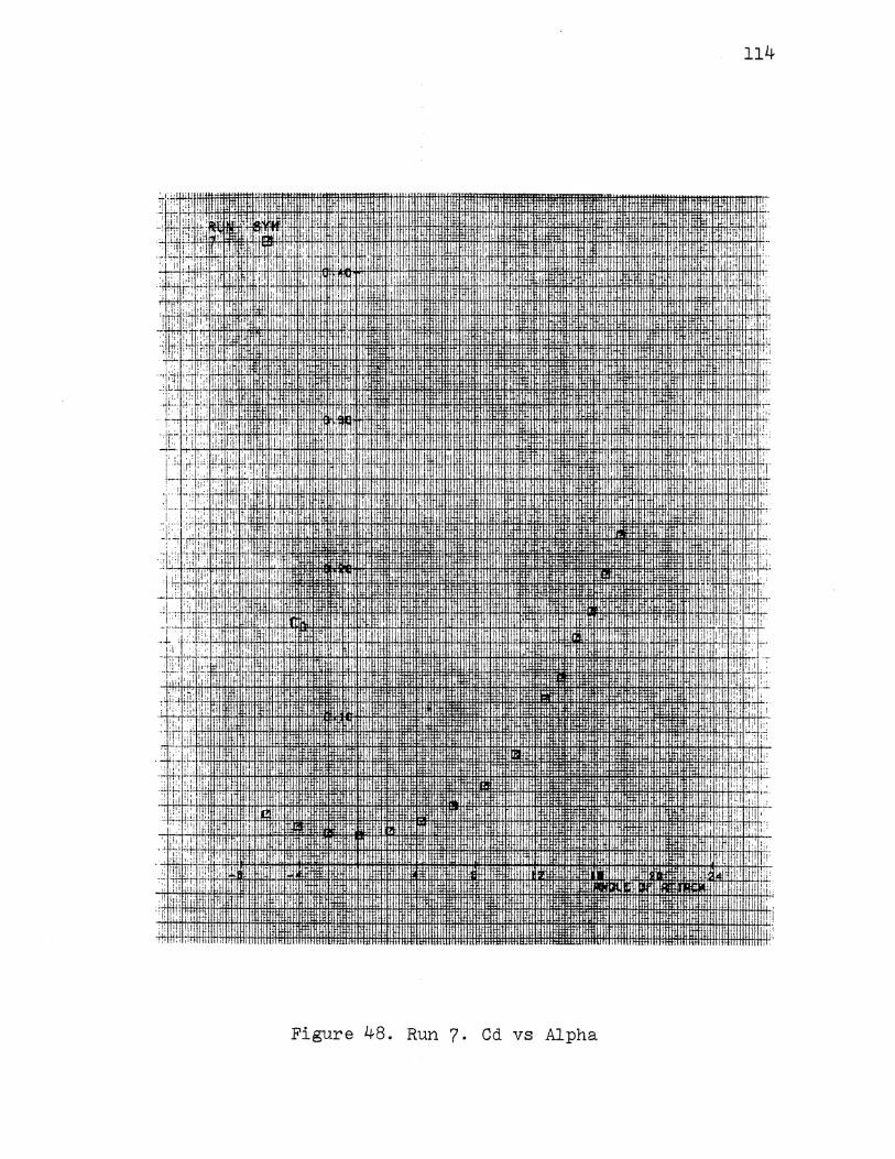
114
, :. ,Iii !if . I ,,, .t i I 1t i: 'I I I ., I
i ,II' :I ;: !:I! :I
ii:, iii:' ·•I' . !. it' 1''
'[':
; I. :I ';' ! ; ; ; ' ' ~ i ..
! .1;: ! ; 11
• .I I'
.:1 : I,' 'I :I
: Iii
I ~· I li i''
, I ;:
1'. ;:! ';I I ;: 1J;
! I [I•
I, i·l
."i
1·: ,:: I !I I .. ,.
'·!,
I Iii:
;:. !:! :!II ''·
li,
Figure 48. Run 7. Cd vs Alpha
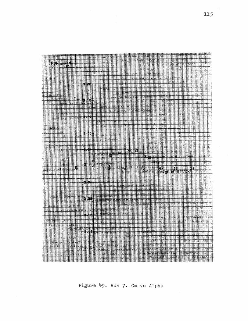
I I
' .,
I I '
i -'l' I , i'.; L :, I '
'1-l' <l.lli~·iii+' if.\~tltrH+I:Itl+tlltltltHfH+i1mfl1t!H!tiffiHt.llt'ti 11H· +f!itlt!±lltfH+fHtHttft.H
1·.:;
I i_\1 ,!
I '
I 1[,
!: li'l
·' 'I i' I I
dl ! ,!! l!i !i
i I i r: "l•i
' !
,I. ;) 1:1 il
: ,, !I! ·' I I
I
II· !I
J
. : 'I ' 111 ~I • i ld I 'I' I
I"; !! : ' '!. li'
'I' . '.I
i
· "!I:JI.fiJ"Il .
BillL
!'
I!
Figure 49. Run 7. Cm vs Alpha
rml:lll
''i·
I !
'I
:, I i
' i
!
i
I ! ,.,
II . '
I rl
! ,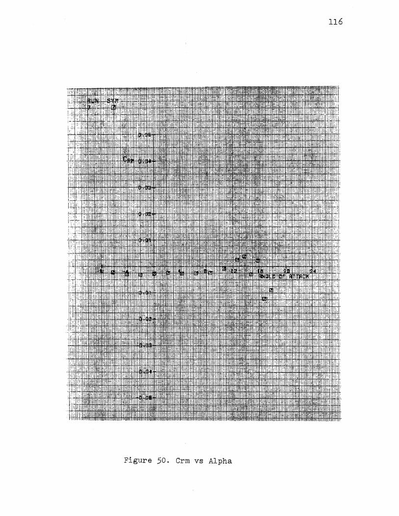
116
,. I . . lm~m .. 11/HIIt :l:ll:lliL"I . ·. . . lliJHII L.:' ' ,, ~~- . ' Wii:~i!· :gnm~!!wm~afmrtt~·: ,!· m~~:[email protected]·m~EltllllllllmllHJUT.IIII-1 IIIII,IYB~·~n~!l~~~m::l.· J::'i )i .'I .1·1HHi
;!·dlm·: · ·•
·-~,::~.~+·,+rl,'fi_,:··~ Hf:f1 tii:fr:.';·+ltl·ltfl-+ltll:il+·~:r··Htt·~H+!t.fi,li~~+;W.ttttl~tltt1 llittl1 ~tltr~U4#!HtBllil~;:_lli+Wl#IH+I#lMBMEMtiil' ;&r:'•Hi. ::H Htt .. H-<;""1'+HT!ffii lf~ltlri•ftt,H *~·:+'·
'i, i' 'i'
'! -·mrt.f.ll. lllffflftttlttt. -~~~~-J: ~-~ _ .. .,N .. _. 1.. 1111 .. 1111 .. ,~ ... . . Ji: : mHH.umwm '"'"'"
+tlt':::.t+f!+lii:+!tlf: iffi!l.. . . • ·ffiffi· =!ffffimtl1iittHII.iiiiiiiiiiiiii'H:t:f:: I ,·,
t.· I tt+8.ttH+Itf!H
Figure 50. Crm vs Alpha
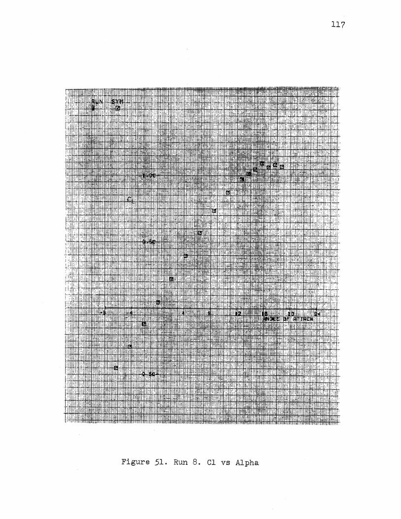
I\ I
I il: 1
':! 1\(,
I::
1 1: :1:
' 1.[
'I
117
I II. ' . I i ~ i II i I
' II
I I
i· I
1'.
-•II'
I I
i ' L'i
Figure 51. Run 8. Cl vs Alpha
'"
,., I
1i1 1!
r t·l, i I 1 I
·''
,i llii i ':
i·
I ' I
·.1
I I I
I':
' ~ : i '
,d :
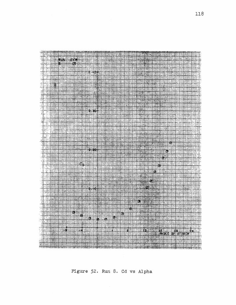
-:: ~!ll ;: I
.:1\ ii ': ( ::,: . I '11:1 ::'1 !I! . ,r !!:
). i I I.
II
·' I'
I I
.; I
'
IHH!!I
Figure 52. Run 8. Cd vs Alpha
I I
I
I I
II
: i
I 'I
118
' I 1: ;
I• ;I ,.
' ' '
I, II ,. ' : :I
!! 1:
I .,
·' I I I•
"I I
~ I
1.'
I r:• I t1r
!I •J,.
[ 11:1
I i I II I I
I' I ' I
I , II [i
Ui r::
! !: r:: 1'1 !I
·rm
':
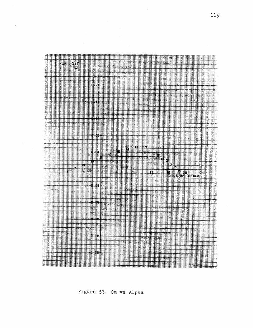
119
I! lir r
1'1 li :r
; ! II :,; It~
'I' r,! '[ 'I 1:~ :1; T: : 111 'j r 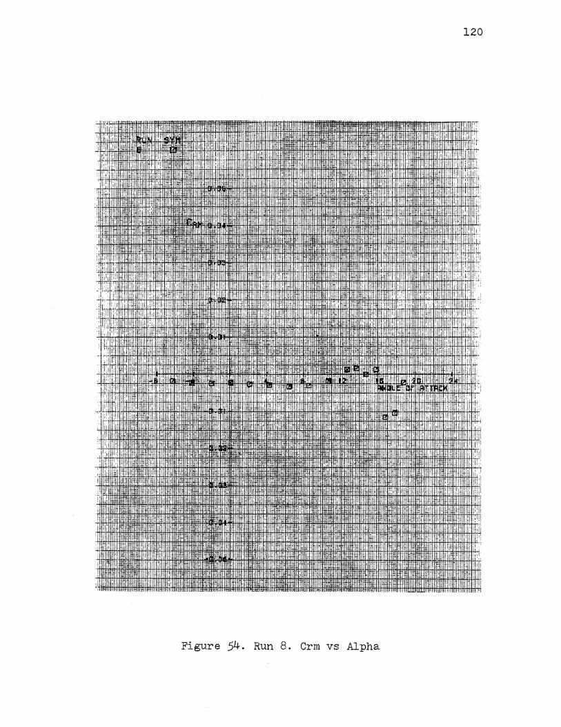
';
j' i I
'!1,
, I,
1::. :1 '1. .il
.. ,1_
i , I [Ji 1•
120
i '
: i ,, I'( 'I i ·'I!,, I' ! I fi .: : '':. :'ii i,! i :,1, ' ,! [I '
J: · : ,, ;, ilil1 ·!:i I : li:! ', '·'' i!ll I I, I', Ill I I
.: I'.
I' ! I
; I!: ·:'
I
"
II: '!
I ttl ,, I I '11 " I l'
II':. hi I
I '!·· ' l , 1: . I,
·::li!: I I
I, ,, (t,
:1:: :t:
I I " I
I[ :
:
·li
J
•• I•·
I I I
I!HHH lllt!IJ'I
Figure 54. Run 8. Crm vs Alpha
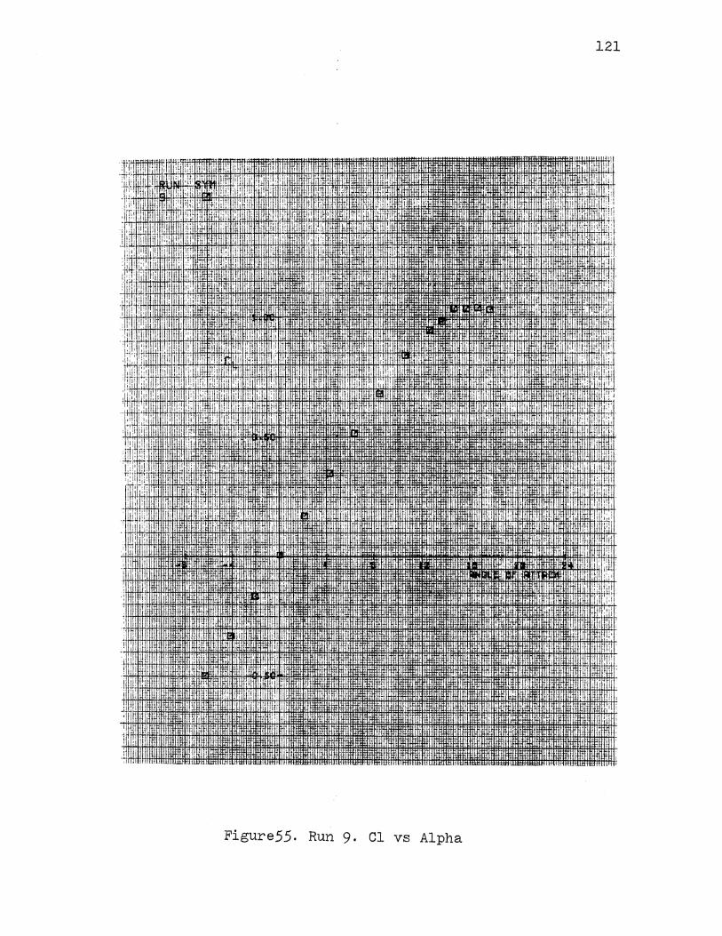
''• 11:
" II''
!•'l
;_._i
I
I
I .I
I" '.i
' ' l!i
1:,:' u i:ii
.1!\ II::
,r! i
., ,,.
I
n !.:1 I I
! ; ,. ' ' I
!1 1
I !:'
li'i ,,. .. ! -II' Iii• I
.;: ; i
I , I
. I 1: I i oil
;, I
I rii il
. lltirnttf I
rrrrtWn1ffil~•llilM~ttm•ll
ii'l, ·--~:H-~ I i ~
• ' ..• 'iahu· ·
'I
I --· m:nm . , .••
I IIi 11111: IJJ.11.1J'.l.."tTJI
il±ll±l
Figure55. Run 9. Cl vs Alpha
121
j{ '
'r ,' I
I I ;r
,'' I,
,Jtfli+Hflttl±ltlffirtH+lil
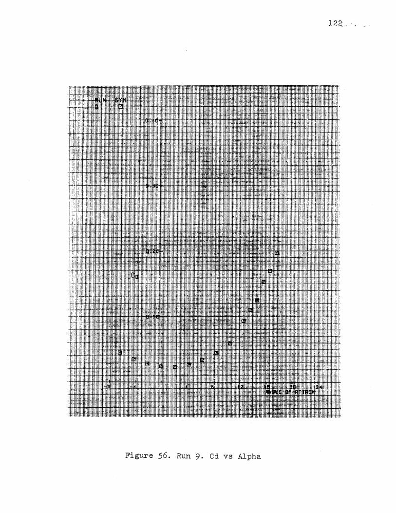
:. I!
· i; IW~I~I.I.UI.f.I.I.U.~~J.I.l+ij.j.j.j.j.!m~ffilllt!HtH H+HH+IitffHtl+HHltl·fl-!Wf!tfH1tHfttfftfftt
~ .~ . :iiI
!i .'
i·t 11 ! 'I ,· I'
I, I
II
H!llHllh
i'< ·~ I;;':": i ' It:.;.; ·4-rt-'+l!i+HI<+il:
I :i:: ,I!
I.
1!,. I
I I i. 1:: '-'1 ' 4 ~~ ··:~:+1-i•t*l+l·IHl+!11 H+H+IHffilfH+Hil·>++H+IfH+Hi !ill ! i.• I• 1 'I ' I
I r~; : , ,,,·:: 'I i ~~ I I
m i 1 .
!~'! · 1 , I
. !
I I I ' ~ ii '~~ .·ti+H·,I-ii'·i> ·J+M-1~-ftlll+H+I+IHHI ff+I+KH-i-IJ.l+i:+1+-:1•· !tf Hfl+fjj+!i Hf;l+fHH+IHH1t1:ft!tHHi+HtH+Itlitltl1tttltHtttHfl:fff!ilitlttl'fflrlftttf:iffi ~W+W-k-IHJl,IJ.I1 !:i ;:
! I,
! ,'
~·~ 'I II
; !i It
:I! I
•II ,,: I· '! I I i 1 i+it+H~ i-4itJI~ H+~+H+ .:.1
::j•l!• . i ; : [ ~ I ! ! I
::;f lf,il:.ift fl1t)lffiD·-LEIIU:Il-1tttlfj~
i ol ,•;,
Figure 56. Run 9· Cd vs Alpha
I
I·
,I!
I
II
! li
I:
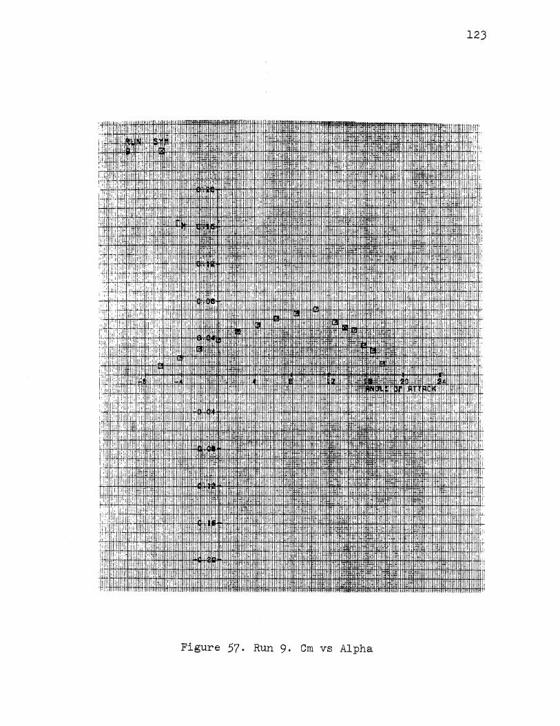
I ill1 ,I JliJ
123
Ill!!' ii! ,:
:.: :+::~i~:H*I+H11m1 m· +!ffl:rH'iittHi+ttH:#tH!ftf!ffh1:ftttttf!IIffltlittt 1!1 1 , : i ·t:·:
1.\1 I
I,; . i; ,·. 11 ~· 11:·~ iHI;IJ-jfl+i•ft!Hl:ltiHIHtt!+tt!tHtffifffit!tttlf111 i+f.f+!li+IJ.l.W.W•lflfi!H#!i+OOHJ{tfl+l+ll#l+I+HH+l+HtHtH·I+H+H+G1fHI+ltAAfHiHtltfttlltt1ittttftttHHf,;liit!tlltiiilit'l !!i.
'! I
ij ii
1 I I dlt.tiU
i:, '11,: i [ 11
i' fi;: I : i ,i I I
i:' ;:::' 'II
J 'i
i' 'ill , I' I' i:
! li
: li , I II,
l!_ . II
Hill~~~~:,::~~~~;· ~:~·~· ~~~~~~~lliHH~~~~~~~-''''''IJim!ftt!:fll.l.lillm~··~~ ·:1: ,:, lMit!.i Hfmi:HI!i
I
Ill ~1[, ,1' : i .i: il :,1 ,. ' I I
I:. '' i'
;.,:,,,Iii ii• !:
1.:· l:iil ! l!: '';I
I, ! ! I i ~ ! i
!i1' dt : I
Figure 57. Run 9· Cm vs Alpha
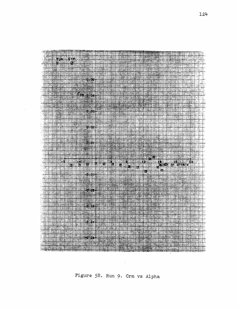
·t· II
I' 'i ,
I iii"" !)'
'I
:.: :( ; •I
":' '
+' :'
i I :-;:
'1"1
'I 1' rr
l
'I
:: i :i\
! ' ' " "
lf,li!ID!llfJ J:lliH.l11 liHI'f.ltll I " li :UtniRtflUI~~ .· ". B
irQIJl.liTLU1 'ltlli,ltl rta
124
"I ! :[1 i ,, I ~ I
~ ! :
:!t I . ~:-
mmr !i;f-"•i'~ '" I• ii· · _dU· 111411
""",
I ·····
L'.: I
ifll!llUl
"'""
Figure 58. Run 9. Crm vs Alpha
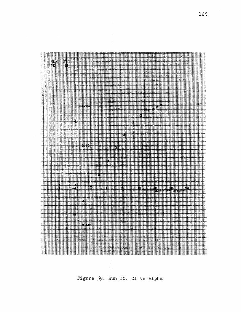
125
'!~
i··, II i. ' I
1: I
lit: "'"'"''
-;w~''' tiHHn
Figure 59. Run 10. Cl vs Alpha
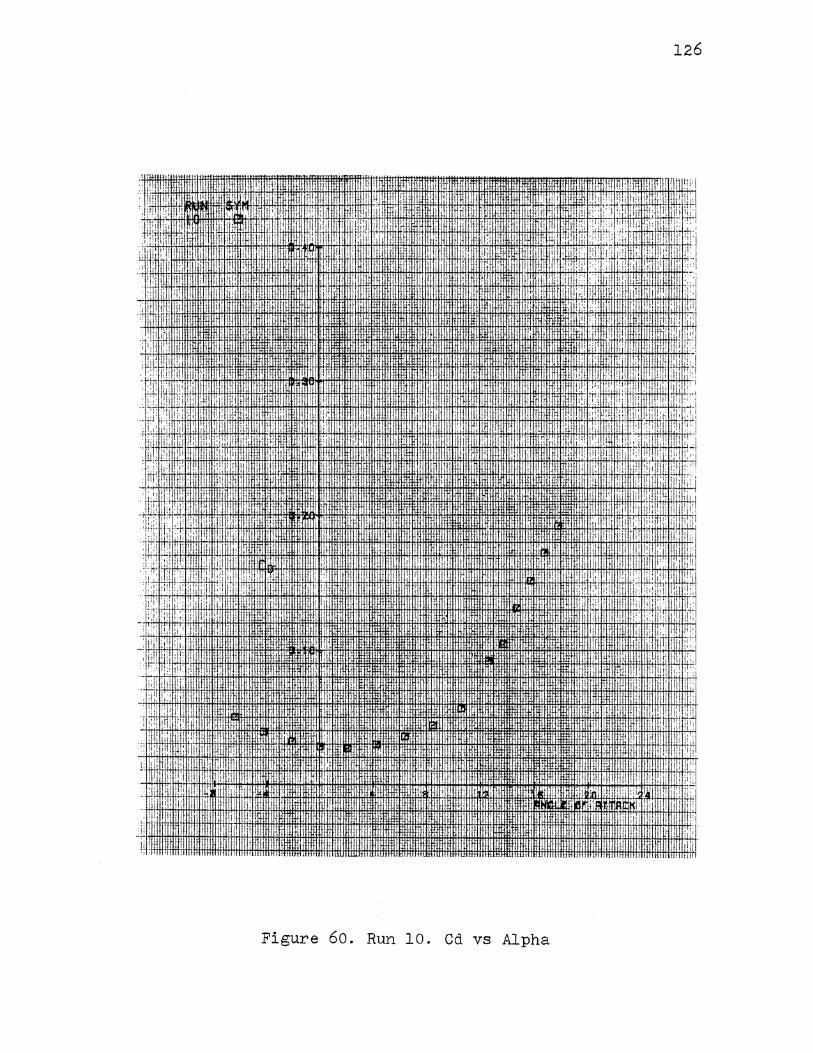
I . I
.;. I I ; , I
.il ;~ 1: [,:!
J: . ·1 i :I:!!
:ni!.".l
II, l:
!:1' i : '
i I
I ·''
I
!:I\ i,il
, n: I·~
I
I.
I.
., \il. :. '
[:li iii. :II L:
'' ''I ,(,
I.
,i I
Ill
1, I,
'I
II.
Hl. 1n
,, ..
: I i 11 I·
!!:
·i· I I '
II•
.'.i I
.. ' ·'
1'.
It~ I
" i
" ,:11
1•;.! i
j
[l' i I, I I ~:.'w i
11 'il
P, I :• 1,1 ilj i 'i
,I 1:·· I I! 'I
i ,:;
.:lj :I
:
I d
! I I !I 1.1' I
: i
I i I I' II
i '
' '!:
·I ir, I
I; ,],,
.:
II
' I I I•
ti Iii llllllil : . ' ltWU .. . .. . mtH!tlltiHilfHtaUmllifffl[-!ni[!!HIHI!lWU!11llill! I
-~"~t~~111:JttiH~tflt~ll~fii~~H:~.~:~t~~~:~~::llH:flltHfffi!ftHttl+lttH+HtltHtll:lllt!H:t.Ht tlfltltHII.Ilt!tt00Ht·:I;Ht. nftH:Itti111IIIU!HtH1rr!i:ltt!mmmmtrlttm ·.lff!tlniU!-l!HUfl!HllllnlUIU!Ii 'II 111111 lltlt!JI uH11 ttlttttiJIIIll'ttW.ttrllttlttll#ft!fuJH.IIJlf[fl[lllHHllliltttlrtrtl
Figure 60. Run 10. Cd vs Alpha
I 'I ' ' 'i
.. I
I "
'I •I•
'" ~ i :.1
·:) f ~ I
:!II
i'! 'II,
'I: I
I"
II: I !
i, •I,
I ,,
i ~ : ' ' ! I
i:: I
126
11 JT. l I :;~~
I !i:
1: . q~;
II l::i : :it I' II:
I' :i.: ·iH
I I 1!~,
. ' il
I if' . I
f; I ~;: 1:•:
'I :-:-!:.
~;
Iilli lltli i I! i!Hflllil 1li 1111"11
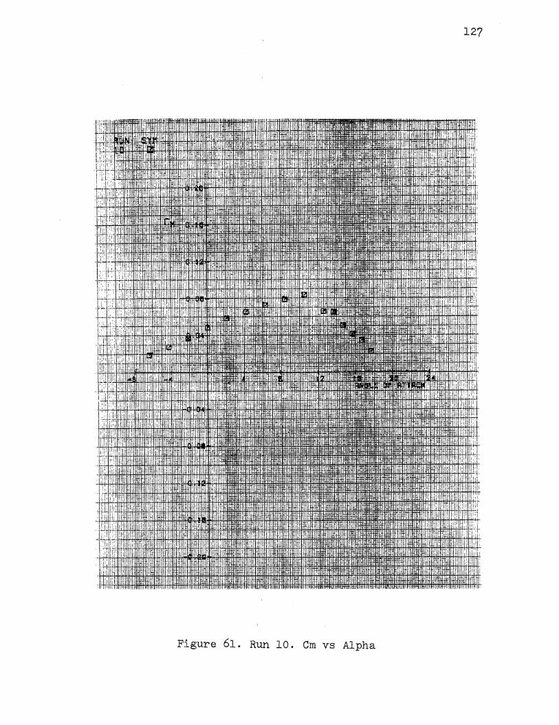
:1:: i!li ,. r;;;r ::r,,
l'r , ·.
• I I
I ~ ! :I Iii
I [II 'I i 1!,
' 1·, I I I
I,
l ,I l!!lllftl !
1 ..
' I' I I I ,,
·,::I' I'
'If!' : ~ )_:
!lit
111
'" 'I --' I •
~~ I
I· I J ' I
I' I ·I I
j;::l ' ,, ;··~I !, I "t)!
1: il · lr: i iII fH I! 11111' iHtlnu 'ttdi111JlilltilllJWitHtl fqtfiiJIHillluunr ttl ttu 1
iilli!iil!lllllltllll~imtt•lltf111iifliU!HIJ)IHttli:WittJtHJ-H . ,, Hfltlllll 'lfrfltl lttltftlll llttllll mllll.lf!fffl#l:!1
•
Hl!ll lltl:fHHHI
tff)ltiiiJJHI~~ llfl !LihUN .<umm
Figure 61. Run 10. Cm vs Alpha
127
I I
I I
I ! It i
I '!!I
;
I
,1·
:1' , I
11t'
:I
I
I ' !I' 1:1'
,, I I I
I'
"l;
! :
! I
llutHLr I!
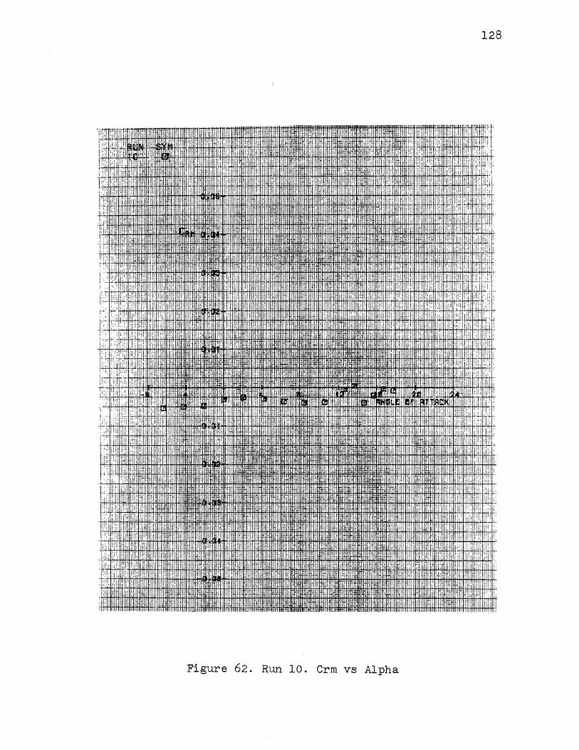
128
.J ,,·m 1+1+14+1-U+J.lmHH+~~t-ftl#.H+fHtt.tttm· :1:: , . ffli!Nil+liill~W!l1'Ym~+tlttlmtlcl:llifillltlffll.fltltlt~1ffifH+f!.l#ffiflfffiAA+ffitH+fffi*ltHffilntl:ttttH1tmt~it::rtt+H~r+t+tr !::! I'
~- : ; ! : i I i I ; ' ;,: . ;;
rG , !I'
,; I
:::; ,,
''· '.' II. '
·, '
I, . I
I
!,II !i: I
i!!
!111 'ii 11!' lj;
'" i I
llJH!tlHHill
"'"'"
Figure 62. Run 10. Crm vs Alpha
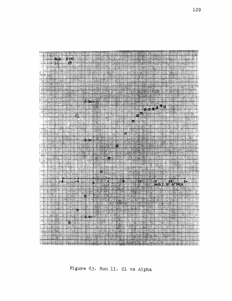
':; '
:, rl! ,, .I
ITllllll :}!!I ili ',' il Iii !!I! IIi I ,I I
: :llll[ ::: I ,,
' .[,
! ~'i , liP r i ' ,I, I! I '·'' :: ' • ~
I I I
I
.~: I : I ~ i ,.1 !!: i''' I
I I
If
I~; i' ,,
I,
:+·fl'
I·
:;jl I
l;l: !i I
I,
. ~t1Hlfl ~tfl i · :m~r.r
I
I I I
: I ilr I ·:I
'.1 .,
'jl .,
,: 1ilf!~ltil+l+~fltltftli:W.HHflfRH4tffiH£H~~~~ I.,
T •'
' " ·i I,. l;i :;-n
I
I I ::: I
II
i ; I I
IT iii: r m '
Figure 6J. Run 11. Cl vs Alpha
!I:
I '
i j
I'
'I,
I I
129
' 'i
I
;
'!:
j:
1:
il+
i!J
' di; !~:
:I f!,lji:
!+l'li::
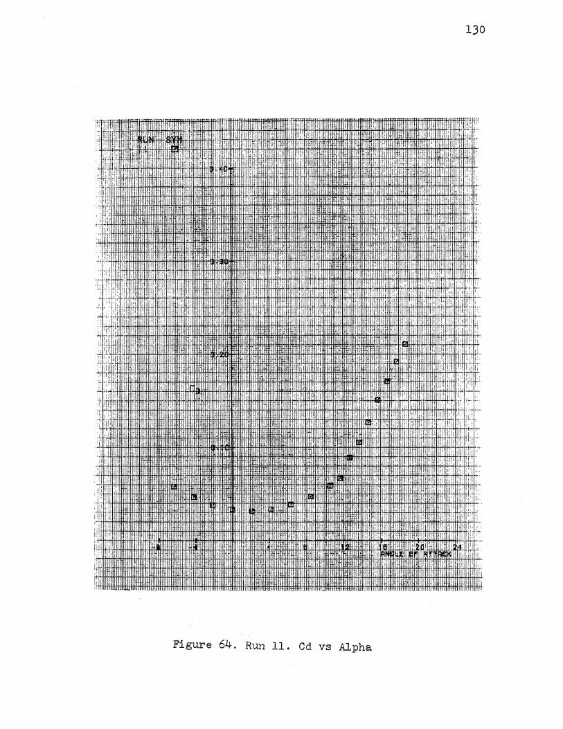
130
·' .. Jl. ll· I
:I ill ,, II/
· : I ]I!! I
: !:~! 1 H+,l ,+·lie IHtHtt
11tHii fi+HHJttlli~~:ittmtttmt!' ~+1-8-l!fHfffitH·I"+IH+fftliiit f.J+IW#lt/J.iJ.f!+H:IOOtl#lk!fHi.tt!·fi4Hf!+f+!ffiH1fH+Mtlttifftltftttftlttrtitrffi'tHfi I: W j;
L': I'':'!
,, I
:I
'I.
'h;.i· q:+J.j ,11!; IHliiH+ftl+lffil+l+i;ffHnmrrtl+ltrttltlitlttli-ff~ ·:r: 1 :~; !i ·. I II
II I
I I HlfiiU. I
' i ''
,•i
II I'·
llT.IiUHTI'IIIII:.
il ··t
iu '·
i iitH !Itt! tftttH+Htftltt!tttlt
Figure 64. Run 11. Cd vs Alpha
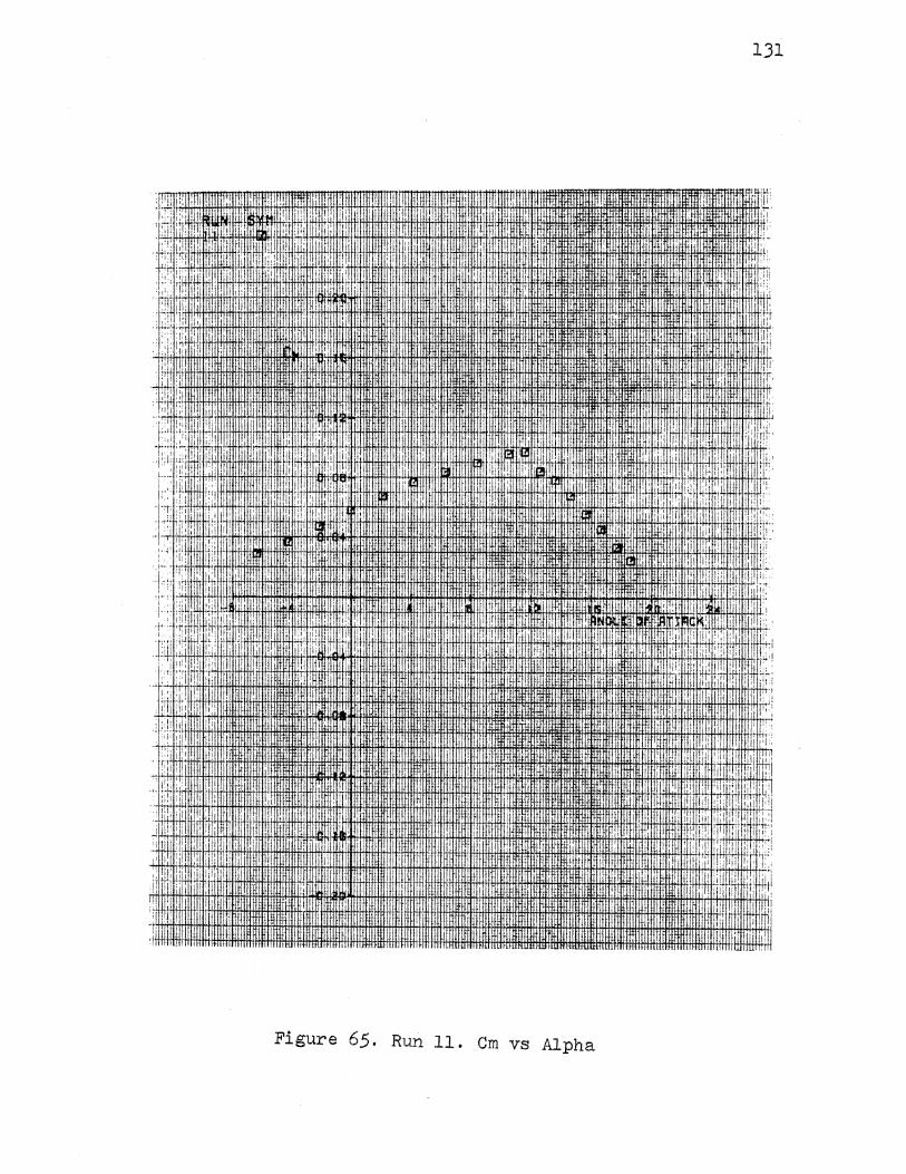
,, lliilill. 'I'
L II lilill ::, . :'j IiI ,I
. ~:: ::r, I ::!1 1_11 1 I
L·· i' t i
·•I ::i! ill ·: ,I '· I !!
. : i I
1.1"~ ~#
!!
~~~. ' lllllf
I, i ; II
i
lfi!Uif
! ' 1 1;' !
:r
lloolli;nm iftl!lllflft. ihif}Uj.lll'l .
llltiJ'I'fM ll:f illf• IUUHW
Figure 65. Run 11. Cm vs Alpha
I··
131
'I • ,' L' 'Iii
i•1 I 1)!:
'' .iffitl. itt!Uttit!!tNtMtmtltt!l
nmm
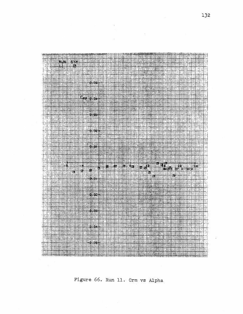
132
'f!ft:'!., I 'ltflffiffifffi'fttr!tfffitffi, :fit, lffiffiltffitfttfffflfflfff!tttffliffl:, 1fffi. m !UHJH+,i !+'H t;.H+·iHI flfl+tfl-!tft.tltfl#l'f!f.!mlfff!flRfffilffffiflf1·fttffifflf f+\IH"'IH+t.Hw.'·!Htt[,~'1 1· +H-1 II+Hitltttii"llii11
.II ;!!i !1 .1 1 ; I !j :I
l::rrj;i:H;: ~~ 11 ,, 1 ,, ,, 1
: , ',:i : ::: "" :, :J+HIHt+' Hil +'+'II lffH11:,11,··H,I fHil1iltltHt'1"' I I I ~-~ (i': I I 1: I 'I If: ii' I I ~'-' ll ,, I
1!: :( :! I :1 !II I I ' I I' II~ II ::L .~: I . , i , : !iH+il+f~! t H.J.tHJ{jffi+~1,JHH H+H+I·I ~ Hi+iHt+ltmitH·HittH 1st· 1tH+ttttHf+H"i·lttfitttt! ttttt1 , 1ttliittni'ttttit! 1 , :+H+rHttffl+tffl+tttttt1 ~t~, _tlth+rltl+itr1H-t,ttth IL:.
. : ' ; 1 1
' 1 ' '1 ,;
1 hl+!tHiittt: 1 Httt11 i1 H .fHH4i1• lf!#HH1
i+i" 1+'t tHHHffirmtiH+tHHtHtttfmtrttHHTittH1 i 1+ttHtttH•Hitiii:Hiffliittttitttlittliim rl-!-i+!littlti·t•!HttltiitittHn 't! 1 H h . I:1.: 11 li,
· : !:; 1 :: u; !I ~w~~~ i ~~mm' w~r~{illf!mt~ftlootljtJ+m#lmtlilltlll~#!mmmrnmlffiltft~fmfHfffmmHlltffil#HitfflffiftH#t~f1* 11;.
: lir· 1 ·;,; ll!i! '! Jll.
I [i
i' 1 11l I i1 1 !! I
I 'I'WIIIltHrtiltHt
r:; !
rl' : I''
I"
Figure 66. Run 11. Crm vs Alpha
Jl
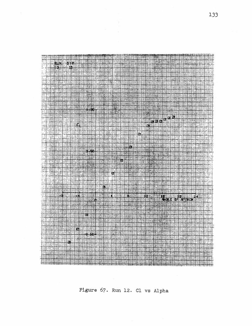
133
:r:ffi1!1; I
1:·;: : " 1"1 ,,
I
·' .... i
' ·,,'I ,,
1:: 't'•' I I I l i!
l;::r II:. I ill ,;, :
tf' 1'
:! ; I I 1.1
! :, I t,
t t • !!I I :
:I! :I I I
:li 1[, j: 'I
i:
: ·u. ,,:,: j~
,I! I I ,. I !! I I I; ,,
I ,I
'rt I
: ' ·:1!! I lijl
t I I I
' :t tit i jll ,;, ! I i t I :
,:f; :;' Jl: I r: I ! " :: : ,, I' I I• t
'I li i' 'I I I II·
'
Y·li:' I I 'I: 1:1 i I I
1,:1 I I ~;! :· li• 1.,1 il,i jlJl il'
! I I t /.~
,,,! ! i i t! I i'' I' I ; ' l:· I i i ·,
I ! ~ 1 ih.:' ,'"' ,:J:.;.rf!tl+i~4+J.!t.H.i.!t+f+I+H1HJ+Hflfl.ij. I ~l+l+fl1+fl!+!+i+!fl+ti+H#!+ftl+i+f!:i!:il+fl:fH:fH!!:!+i#!+f!+iffilt!:!l'l+1tl+!l!tl+l:ltl:t!lti+I:Ht1tltltH+ftH#ItltltHitfhtttt!1+Htt I
l:i 1: i -,!!I ,t I
~~:: 1:: w.u.m:il" 1 ' 1,,...:~: t++:1 li+l1HH
1 fl.ftittflt#il·mHAAtffiH!fl#ll#l+H!!i~llifJ.H+HffH~Wl+l ifl+lflfHmlfflftH!i+l+H+tfliW#ltfl! HH+H~H+fjjfftH+fi+HhlfH. 1+!-H, i'
' ' ,u f ' 1 , ; I' : f!·H iH+H+m:-t+! 'il+~iH 4~fh~H-IHH+4+1HI;H-I+H+t++HHW+ffil+rHtll+tH++H1Htitltl+tttt+1tltt: l+ltlttttrt+Hfttti+tt+iitt+l+tn1 !rt, .:' H-11 '"'' : ~ , : ;;l·i U' ;1 11 ,·1 ::,.
'i
, I' f.
I 'I
i' :·,
I"
: I
i
i
i II
I. I
I I
I, ;: r:
fl t
I
U! tl] :II .I .,,,
!'. ; !.
! Iii, .,1
!,
'!·
I • ·IJ
i
'i til l1l I ' j+l
Ill· ·· 11
t'f I : I
li.
Figure 67. Run 12. Cl vs Alpha
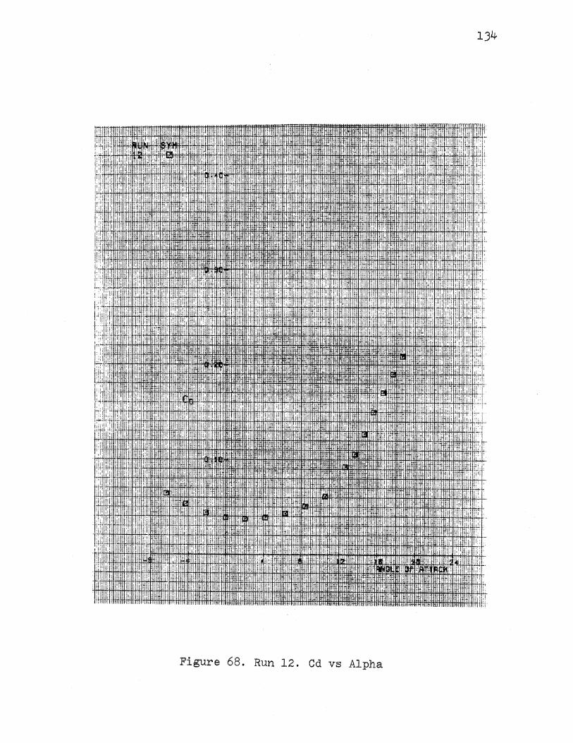
•'I
:,,
'I
I i
'rl
: ~ 11l II'I.IJUU.IJLL/I.JJJLJ.JJ.lC
II I'll,
,. !''
i
i1il 'i
1'1 . , " ''!'
; :I 'I .
m II ltl II: I'
..
f,III.JWl •••• .)
I
I I
i i I
I I I i ' I
r· I'
Figure 68. Run 12. Cd vs Alpha
134
jl
~!., :I' ii: i il 1 *: .! ·I.!! .:· !::
'1 1:' I' !d '
' ' 'II I I 1;
'I:
I:. '!; ,' i I I. I
l,li
I
;·: :! I
I. I :
:1 Ill !c-·· ;r:
Ul r:'
I'· :01
.1' [1:;:
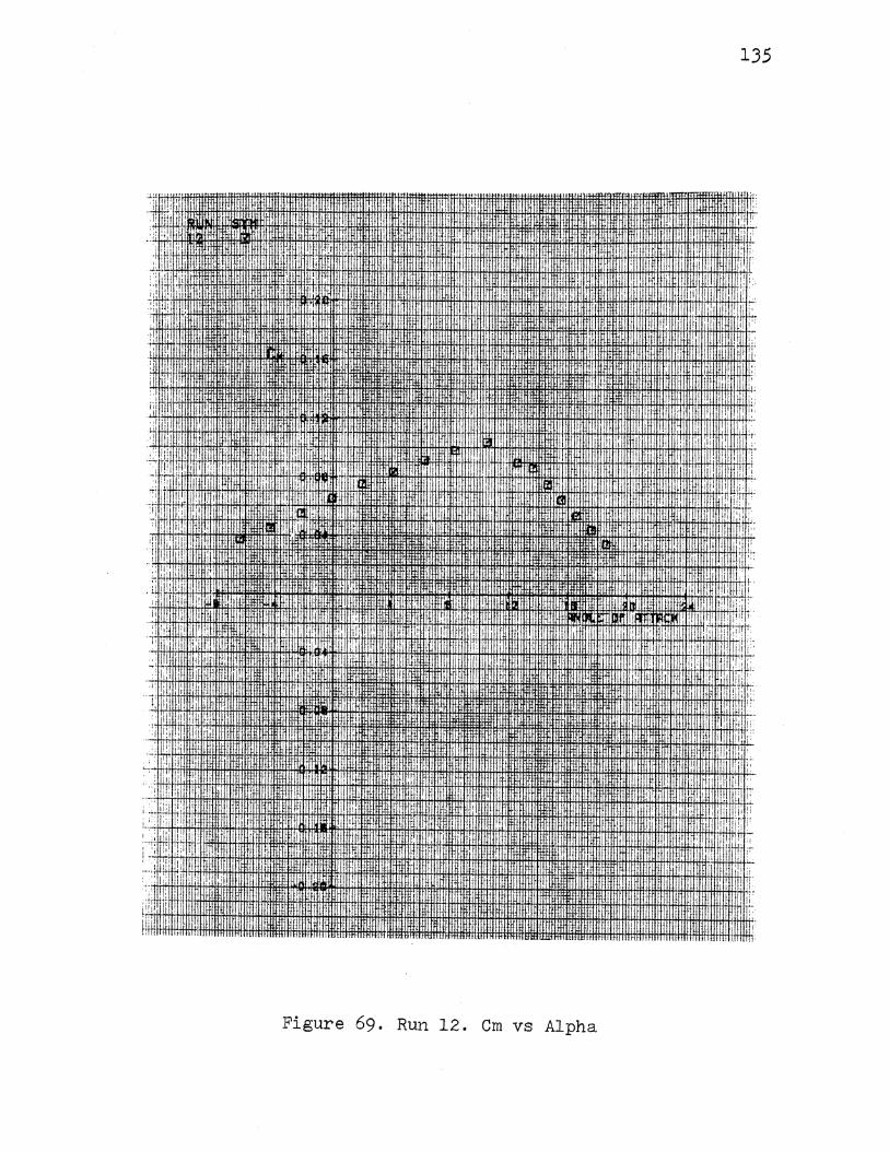
135
"+'H'+ t+Hiltlffl~,~~~~~~~~~~~~~~~~~~~~~~~~~~~~~~~~~~rlf: :-+l'H'i, .Hti!lt "'·H-fft!ill , ~-U!W. I !
·,I·' . 1i
:: i IHI'!II
·tliitil•·ntl-tt!ttiUWJl'
:: ·,,
'ti+H+I+t ti tHffi!llilfl . 'tE I
ll!ltl~ llJ:tiJ:il:
ij ..
;:: ' ·!I . !
'Ill
II i I
:1 I " I
-~ 'I,
:'
,'1 i
. J: II 1
rr. 'I i
i! ,·.
.. :
''I' ! ~. IH!dii·III·I·HIHI
• :! '!!;I
'i:·
iiii I• ,, IIIIi
'I' 1-•
fllillll ""'"'
llnlrtml
lrtfiU'tt11
I'.
I J
I i
. I
~j:
'r
··~~~~~~~~~~t~mma•f~'''
• I· I I'
";I : I
I I
fHtiiHJ:ftll t+lllll ltn!HI IIHWI
I IIIII
I 1, . _:
II Ji :'
.I
; ::
;, '
Ill·
Figure 69. Run 12. Cm vs Alpha
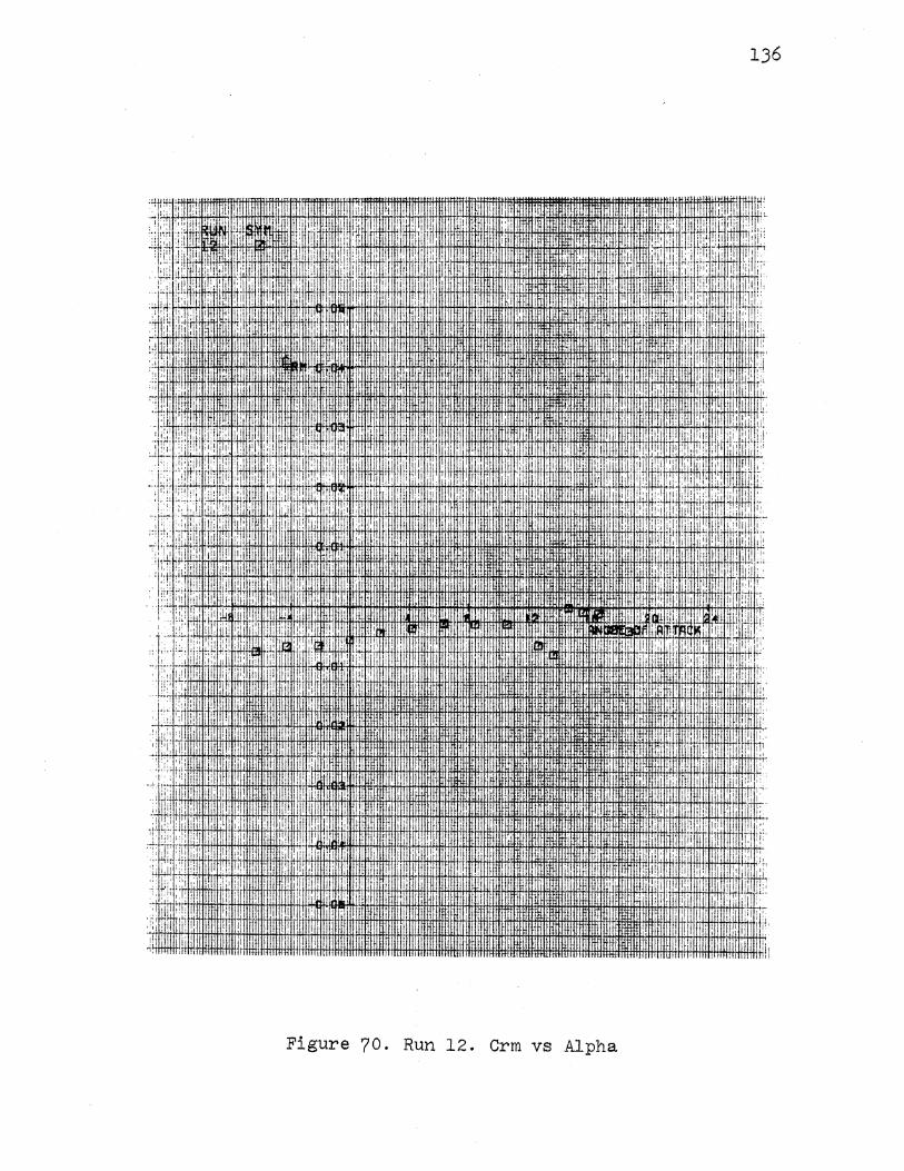
I !.,] II' ,I t:! I
I :, 'lj d!i .~: ;
: ·:L .i!: '''· I : ' -~·IH[! ,!l I 'I
!! ; I > p ~ ~ 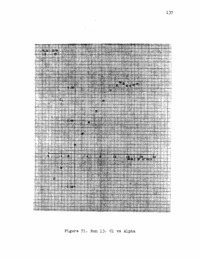
'i'''
! ' :1: ·'I
I. ,,
• •
137
; ::
' : I : ' ~ I ' I: I:~ I :, f!IJ
·, ii ;I'
I l'i: : I [I
I, : 1:: : ' I \ ~IT -;-. F~ ll-!,:-'1 1 Hi-~·'+111 1t' 'fl-i-1-:i' i+1 :1;,: Hi+i-1+'-lfiffH+I+H '!( 'I , ; ; ~ijl.c.. i '•!, :;t l1'• 1 :, I I ,1, I :, it .i,f:': j
' ·~·~')' "' I' I . !-·:·' ", ' I, ' I .; ~ ' I I II .I ' '• .,
. '.i '!! :; ;!
I'
'.
'· ~i I
I·:, : I
I ,1·
I,
lffllml f!Uiffiil
lttltttJ
..I
Figure 71. Run 13. Cl vs Alpha
'' I• ii::
•:,
;I·
'' II'
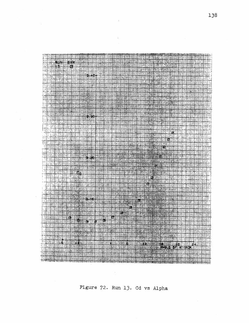
) '!I :q I; I
ii 1 ,, ,,,
!' II'
,I! I' I
i! I ~ I
H:; I'
l,l
'rl
I '
I··
138
'I
I:U:lllfl
1,:
'! ' I
I I
I! I l_i
• '
Figure 72. Run 13. Cd vs Alpha
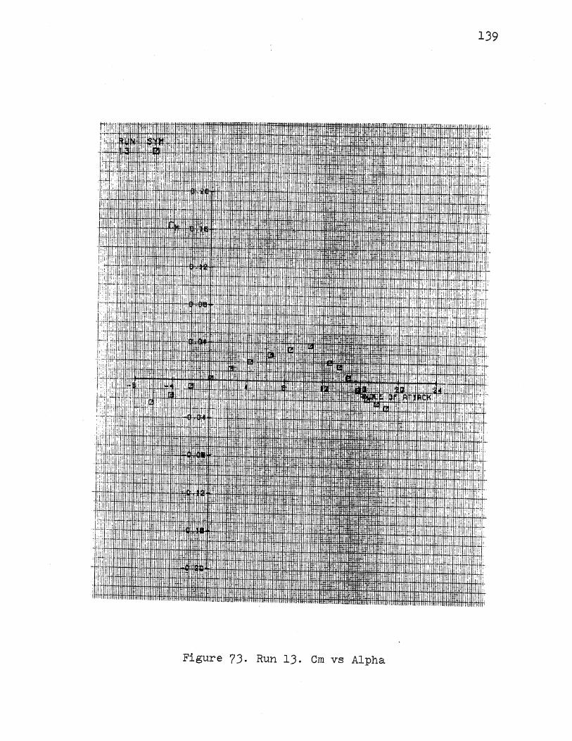
I !I'' !il' llill ,, I' ,I
I
I ; I I I I ' '! I \· •!''• il. :!: ,,,, 'I : I!' P' . :I: i i
::' 'il I I'
li i I
I'! I ,, I, ·I I !
,· :1,
,,
I
•I I I'
i ., ''H +'+lli+tH+!HiH-+It+fflt+I+IIH+IIl+fH+H+fi+HttHHfHl+HH+fH ltlltftltttH1ifHfHtltlttitttH tt1 !tl:\!+ tl±ftlttttfftHH+IttHttf+lltH'''!-i'hH+tr:H:-tt!-1 i !'+t' ;+'; H, tltrf!+H+ :! il' !'i' I lil', i I i
ttl. I'
I. !I!
. '! 1 i:l iii /j.'il
I .
. .I
Figure 73. Run lJ. Cm vs Alpha
139
'I dJ. I ~ l 11:1:
' ,;:(d. ~~ i;rl ;-! :''
I ,, •
I '
!H '
•! I :
i I
!I:
I .II
'': ' !I'
,·i .,,,
! :' :: ' i. il m:
' ,;:
' ·'1: li! .:·• ,, i
/!! ,I·
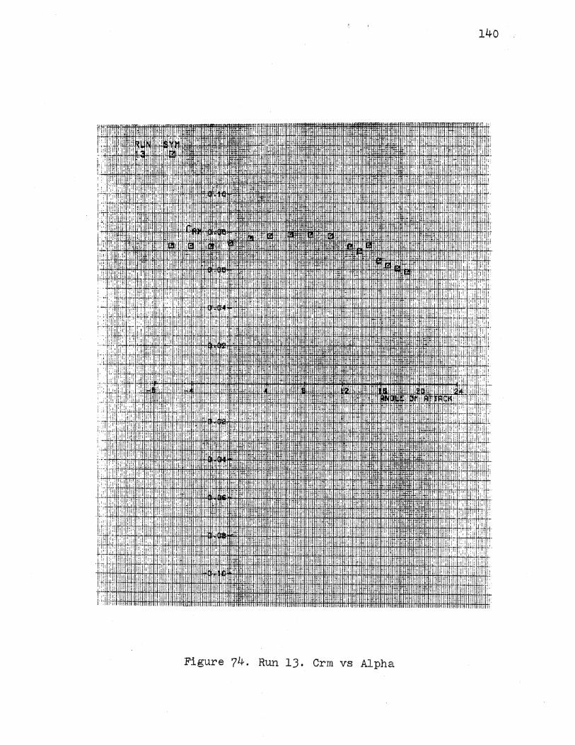
140
!itri •• •
' '' I I , ... i;fl ' : I
II [( I, :r.nm 1Wl111··
I
rrt I ~;i I I
' u I'
: ; :JI I li :d
1::: m ~ .' I i''
II 'I ~[
'! tfllttfl'
pt •, !·j li' II
i' I'.·. ·i44J.Il+l+!+i+l+l+tli+I+HititltH+lrltl1r I fflfltlttttfli'Hit.tlltt!+Hif · . • ;~~1.\H#!tt+~ii+l+!iHtl~m~,~~~ •. · .. Jiifm • .•
!1.
'i .I
It! !i! ~ lU lfn. !j, !i'
IJH I!
11111111111111~1~~~~~~ ~~·~i! J[[
• HllttJ.
Figure ?4. Run 13. Crm vs Alpha
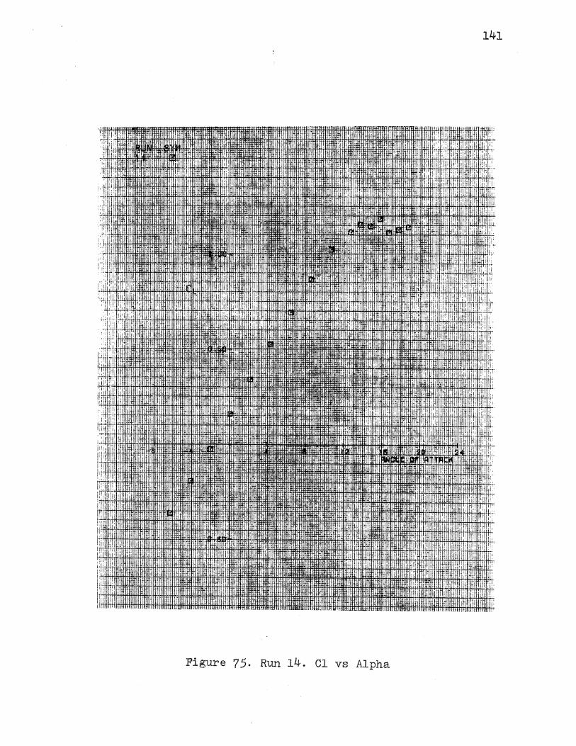
141
·;l I
:ll I :
't
1,·
!i I
>;) : I
! ;, 'I !,· ' ii
I 'l11 I :I 1'1, 'II' ;:,
l•i' t!' ,. ~ :.
I ! II I ' i
' I
; h·
'" ; ' I ,, I
Figure 75. Run 14. Cl vs Alpha
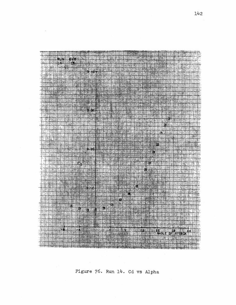
·,' I 'I
Figure 76. Run 14. Cd vs Alpha
'·I
·.! ,,
I,
1', I
142
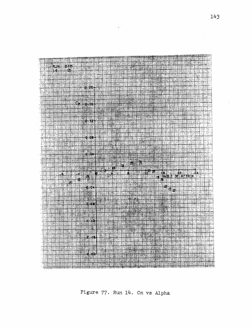
143
IIIli I
,Htt+l'tl+tltttttffiti""ltittl,1il TI 1, i I Tni!l Hltlll ! I ifMll!ffl Iii iJ!IUi l
'·'J
till
'i rn . lr
. '!"I
"'1!.1 .1111 !1.11 I !II
Figure 77. Run 14. Cm vs Alpha
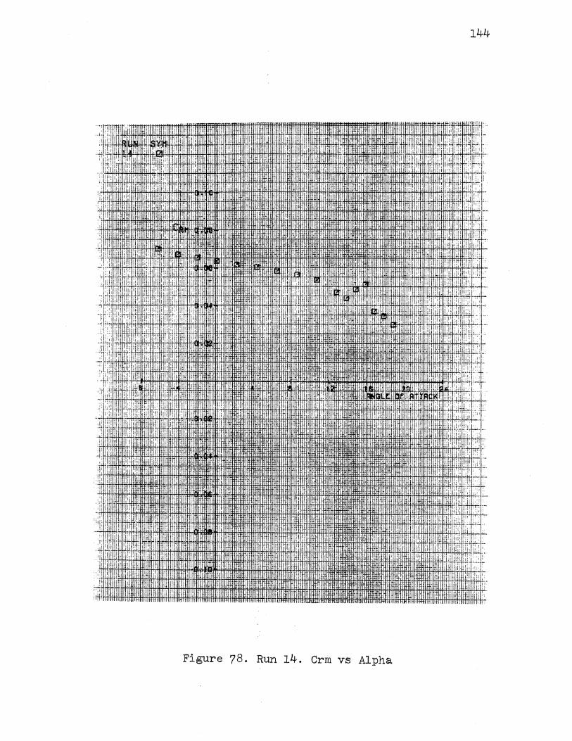
144
• I - I . j '!: i ! .. : ~IT ~:7· J l:::;
!, :i :'•,ii •. · i'!
' :I • t 1 i r ; ~ j i ! tr : , I .,
Ill, ' ''· ,., ! I i.i
II:. . I
•
I. .,
!r·
~·I .. .
. ' lifllllt 'HntlifHitHI~ · llilltlirlllltlllilWWfllltf!lmmJ.InHmmrmumnrtHUHhmtff!l : But · iiJt!tJUWH : ·'·llllllll llt.nHtllllllrll .. l:ilfilfil!nlmrltnlmumr '"'' mmmJJillmwmmuwJrru:~.J:~f'"1 '~' .· nmtrHHUJIIIHIIHttl !ill 'l.llllntiTTihtl! lliltll. 1'11111!1111'111111" llltNtll flfJifHttUIIIIIJI'I:i'IILHJIHiu..- "'"""'·"lltll'>ll lltll'ltti l'lltltllllll '
Figure 78. Run 14. Crm vs Alpha
:I
I I
i:l. :i ' . :L .... ' ': . f'c;" • !'r! .: ·.
.,,;::: ill'• .,
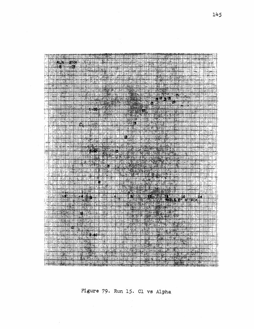
145
Figure 79. Run 15. Cl ve Alpha
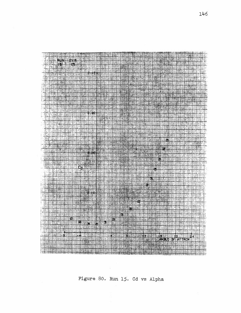
146
. liiii .· :I
iTi 1 • !1:
.,: ·: lil
: •• J i ,! ! t ii ·ti
j·.: I'
ilt
I 1,! .!I
.I:
I:
"'"'". II:
Figure 80. Run 15. Cd vs Alpha
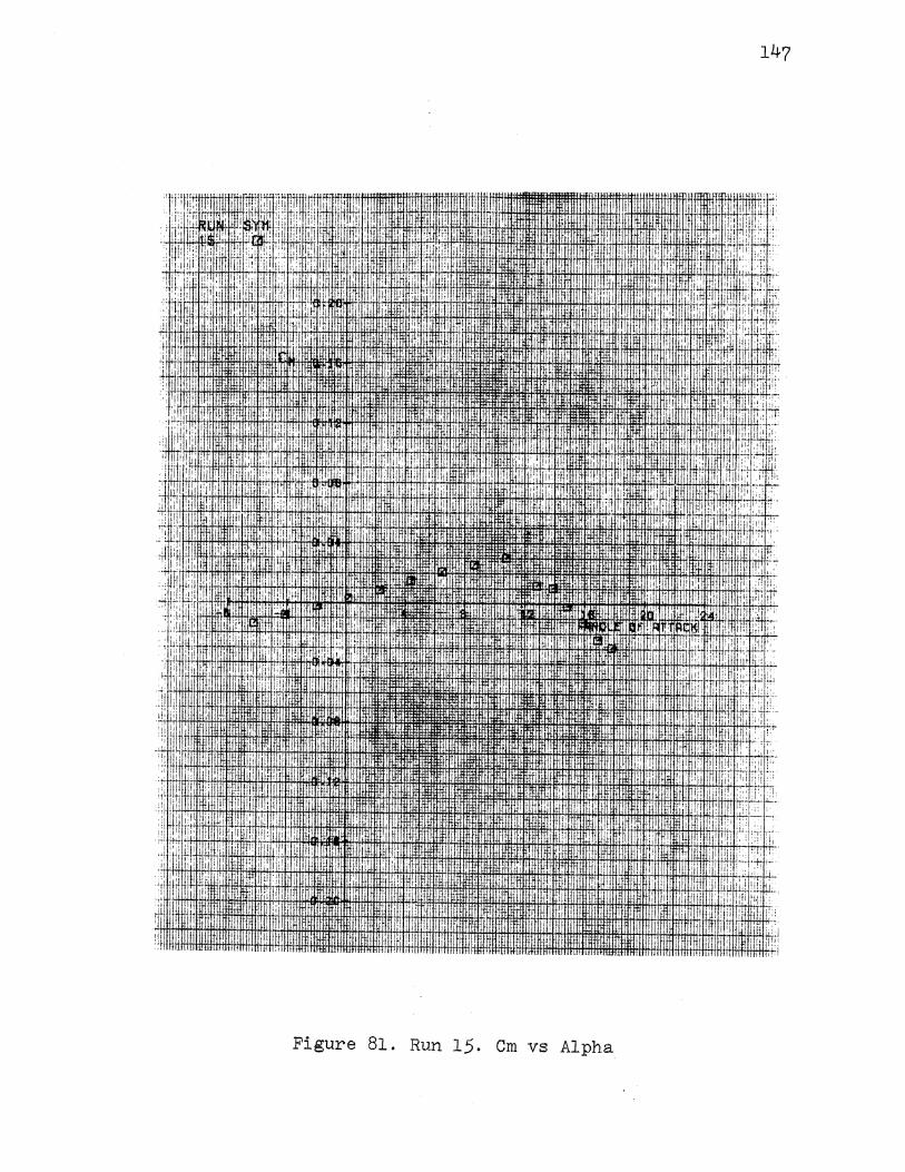
147
·! i ' I. " " I j I
[I II .I I
:11 i
:•!
·'I I .!!': " '
.I ill i ., ,, II i ,1!, II '
1if1 I :I II I, il: I I
' il ;;. " ' I' I .i ;t
i!i II
li[ I r:;
' ' ~ i I '
I
! ~ I I il' ii' .II I !
I !!I
! I '•i! .i! I
' ! •.I
I
Ill
i 'I I II! I' ,,,
I j.l·
I"• i" I Ji"l ' 'I I
1, I ! !lj I
I
I I
Figure 81. Run 15. Cm vs Alpha
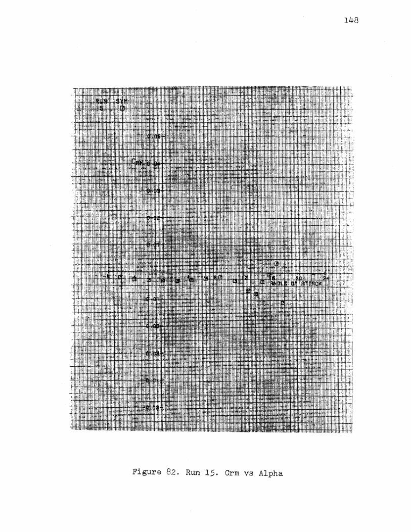
! I'
"!'
:! i I
I' . ~ I I !
, I I ,I " I
Figure 82. Run 15.
I
I
I
I .: I
I'
!
Crm vs Alpha
148
1.11 .I ,,, !'
" ! i ill'
,·. I. i i I
I !i I
' il I
I I
I. I ~ I
it
'"
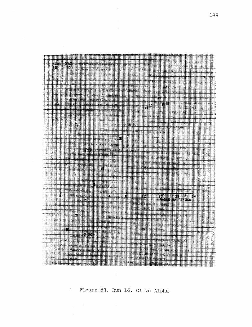
,. '
i ~~.'' "" ·.
,J!'
:1' I:::
'.,,'
' . ' I ! ~ •I,
,. '
' . ' ~
I :
II ,.
' '!]
'·i
i •. rn_wmJ
·II
,HJ.i!J.'·'· :gn ·.
I.
!l#lllt
I ,1 , i 11 I .if. [j!: 'I; [L .;;, :1 , I
, I I'
I '' j ~ 11!1 I'' !}: '
i hliJII&Wi:lfiitim:l'fiol~~t!oM-ttftt~t'Jttil: ;
Figure 83. Run 16. Cl vs Alpha
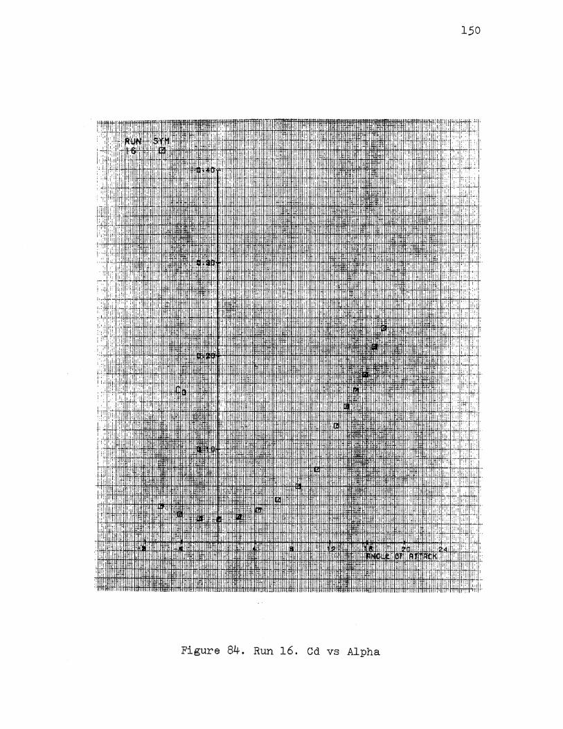
150
. : I : l!, ! I
1C:
., i .
i.
!l I
., l
f:: :·i I-H+H+l+4i-4.J.H1fi:l:l:!:l:l+llifl j : ! i : ! ! : i ~ ! ! i
:~OOJ.I.Ijj.j.J.lf!.J+l14-~i4+'q: 41 ~ 1, \ h • 1
• d, -'! , .. •;. :' ; :
I !j' - I·
I Iii
'Ill!: i• 111 .
• • ,~· li 17'1 ;:i i I !i>:
• Figure 84. Run 16. Cd vs Alpha
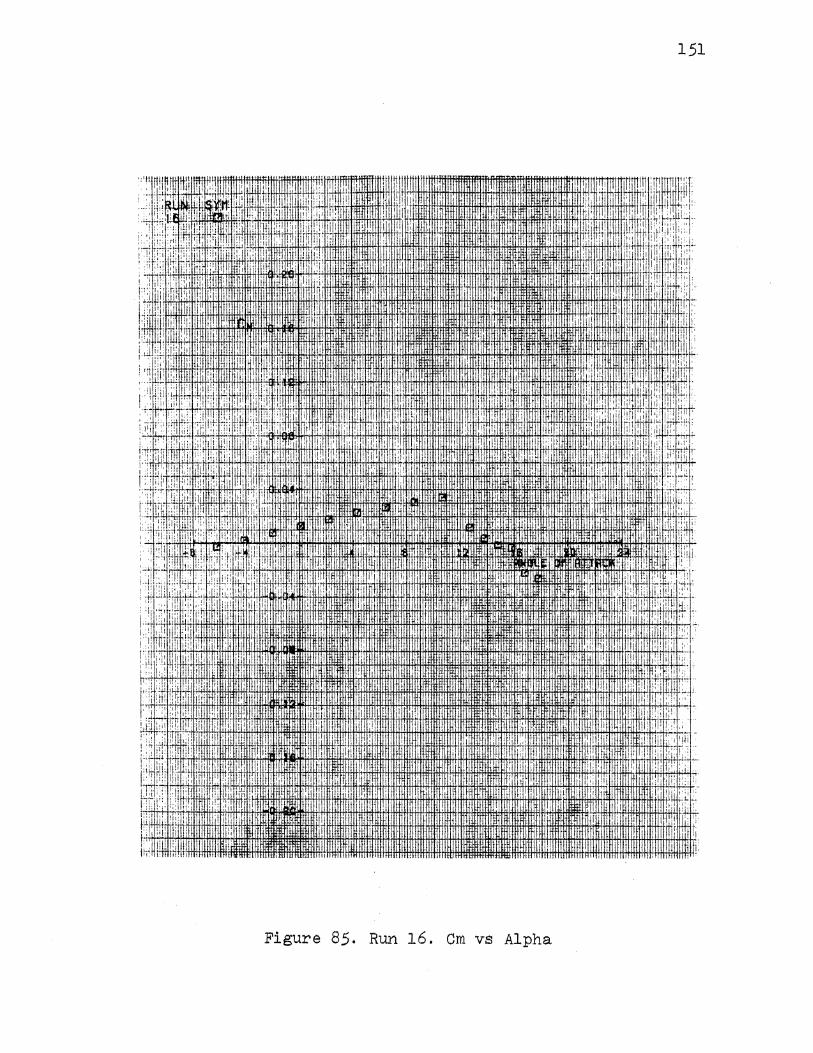
':'H m ., :.:, I ;(· ' i :;: llf i
'! ,,/'.!•':· 1: .i :·i I"'' i i: I ~I, ; ·! I . ~ ! i!:i ,.
1lJ: I i :l :'•! ' ·:1 !. : !'I
I.' ;,,! :' l:ii '!I H.ii!'· ·., 1':
li 1i!l
f';
1,! ill
;··· II: I.
' I I
'
:i I
': 1 I " rft!J!ullltwm~t~m1 m· ffiffiHttttlffiHiffitlittltmtft!tti~ffitHtt!tlti#!:Hmtllftltffi
151
::~ I li ''I r. ·., '' i I li:
i l·j ,, ~ " {i " " ' ! I' ! ~ ~~J,. 1'1
, !i '1:; I ~
i~·:
., ·~,
I ' :f~ i'. rl' II
., I ! ~
d I
!II' l~i tii ::::
i ! j· : i:
j.l !:: :··
"
"' :I; I ;:: ,;
~p
i' ' '::' : ::j;
~ : .;1
' l
•;j I
I• r,, '·
lil ,,HIHIIHU -UJHHlfHHillllltllliJifllill .. ll.lWtll!tlftflffllfllimWitmtNIJI U I II tlfl Hl!J lllll 111111u1 mtu11 ntH I HII :it!-. fl.lii:HH~llttlf11H+l+.!tltl111li+HH i lll++llll!! !"* llllfi!I+H IIH~II+I+I+11#11#14+1+H+H+111i++l+I+!+!+Hi' il~ llllTFllffil llllli'll IHT!lll ff!Tff!Imtt:1111tltrtriii11Hr :i:HI:ffi:Hi¥.J.;H9f!tl!llll!t!+lilllf!#l!tlllltfjfj,i+ll+!+fiJ+I+H+i*fi+J+!+fli-!+IH#1¥.1H!
Figure 85. Run 16. Cm vs Alpha
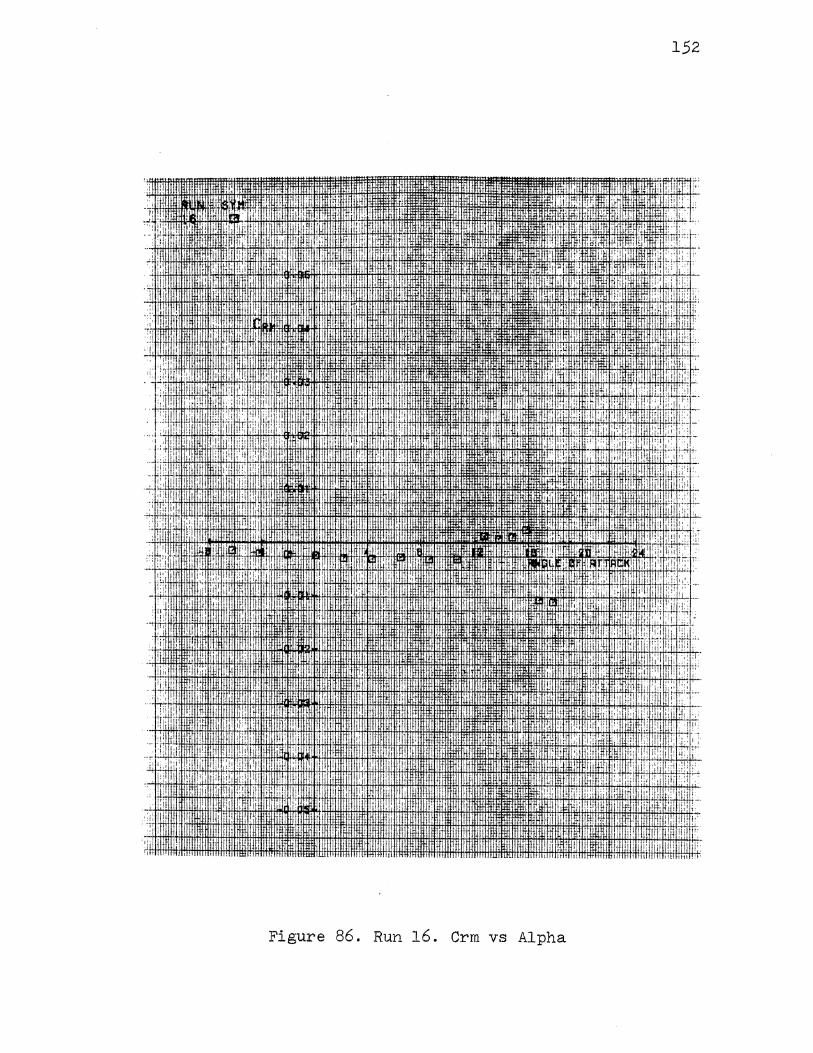
152
:i • II· .. ol ;I! ~~ i•·
. ~ ' il! I f'J! I iJij '! j: '
!I F '!: ' ..
""~ :I 1;, I• • ' i! .. ;.:
... · ' '.i •i• ., :,1-',j' . i!"' : ;
I
~: I il • ::I ~ :: r:! .
I I • !, ~C '
I I 'i :i;: '·' I :;:8 : ,,
i 'I 11: ! ,, :,:n. I
• .1,' oil I l!i II'
f, :I:
.·( I ! l[ ., '
tl llih., :: If! ,. '·' 'I :1: I'· :I': 'I
1'1 dil I i II ' '> ' I ~:·: ill " 1111 I • ' . .d
·I··: I
I ;·:!l 'i, !pi ,.
I i a:' I I llf ,, lll' I ! .~~ .. ' f I I ! I.
;i 111 :I ! 'il' I I! li ql :li 11 11 II! I :, :~· Ill I I I
.' l!i ,I! •I :: 'II I '!, ,,;; ::I '. ,' I
I ' '-d I : I I l ~_l.i Ill I ·: I, ·II i' !!i I ! I Iii: I! I ;:''
··-1 I ' i I .i .'I I ;;!: ·-:-:
' i·' :,:
' I • i:: I.
.: •':: ' !'II I. 1tmltl 'I>W:ai'EI !I :: 'i
.JI 'i'! I:.:; • : I ! I ·II 1-1 • 'I· {L1 i ·· ... ;,,;
1,:! I ·I!, . I '::jr. I
:: I I' ;, (:i :t;l II jil li· ... 'i' : ~ ;~: : ·'' !
~-
' 1;1' !j
I! I j:{ •• r:; II
·'•·' l't·' .: • !:.' illi:! !I tilttf I
'!!; I 1n11 II r:rJ. I i!i 1i!t, ! .I :;FI . II el:miH :: ,.: I
II ! ~: ,. i:' i ~::,, .. [! •. ! ':i
t.', :i:, li•
l~L I i !' I 'I
i i •! I! "
!iii: ·' ,i;t I : IT I' I
•' .I ! !1i I' : I I'! I
.:n oil ,,
lt .,
I 1: Pi f " !:: II::: :.;J ·' i:!
f ,! II i ' i I II ,'i ,; 1'1 iii· : ill' 'I I I
I I 1: 'I;, '
I •: 11. I: I' :-!-1
·+ I I! 1: I
•· I',
··:, •• ·I: ' .I
Figure 86. Run 16. Crm vs Alpha
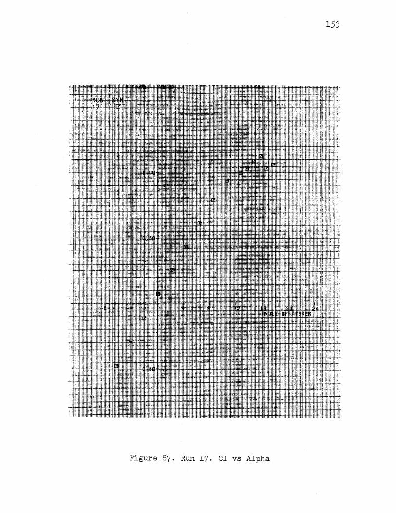
~~I
I .fftftm.1
ttttJ:-1! • l :! :.l'~llfH+IHH-f1 1!: " ' 'I .I'
.• : j!: ' , •.· 1, ,'frl,·. H41FffHifl+HflfHHfiH+t!H3:f"fff'·'li+fffH :•' lj'
,i :II : I. I I
r l1
Figure 87. Run 17. Cl vs Alpha
l:i i :: ,i ;.
153
~l! ' .. I ,;i ,,:
I! : 'i; ~: "-· 'I ,q :
: i. I:: !/1!
" '.
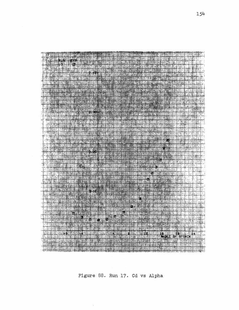
154
Figure 88. Run 17. Cd vs Alpha
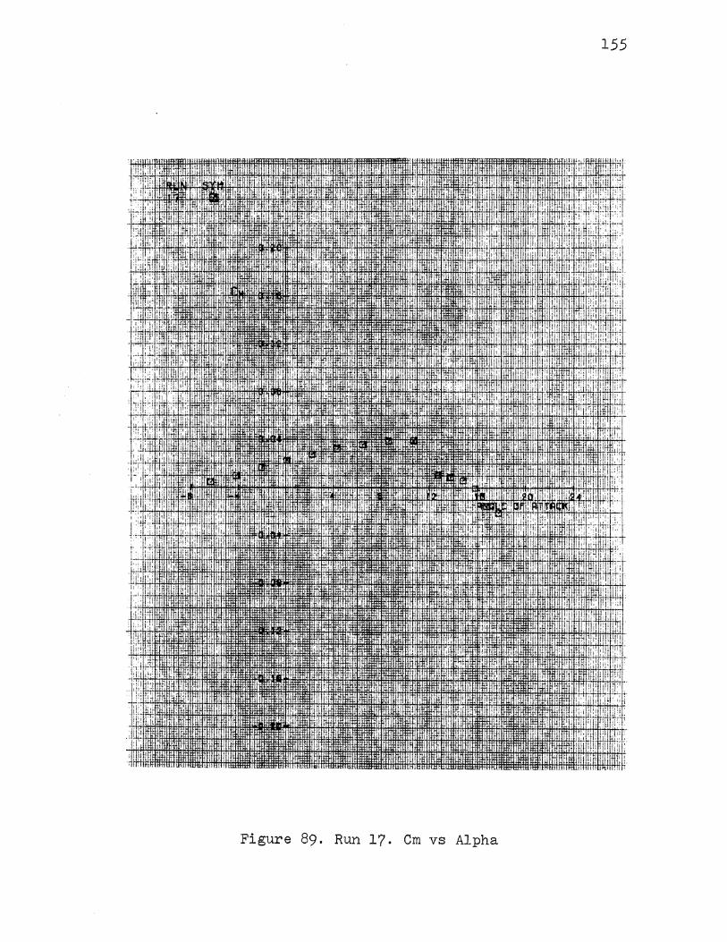
15.5
,..
!'I ': '
i I I' ' ' I' ! •I :I
i !I 1: : i 'I "
·! I · •. 1 ' : ! I I.
I
1: II
i I : i'
i !; ' I
: ,. ·I ,;
.::l I I
i
ii I'
Figure 89. Run 17. Cm vs Alpha
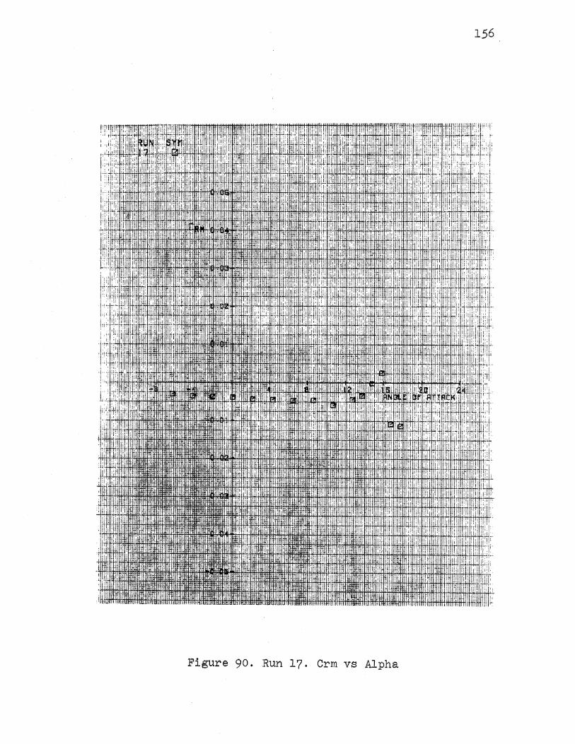
156
'· :1 .'!: .I
I' II' I !: ~:,' I
111 I! I
'! I [;~: !' !I: '.i!' f·
I I
I!~~· it ~~~~ Jtil I
!hi. II
" '! I, .il I,
'Iii 1:, iii ~ i II ''i .: 1
!I: ,, l''::w;:; :.: :·~; 1'. ,I;
I ', I ' !J::' ,:, II,
I '!' ~! i: I
i .. I ,I I I :i! ~ ' :1
I ~' il I! '
i' ! I
: .. l!J L., ~ : !
i:j'fH ·I iii i · .. II ! !
Iii[ Ji: i. : ~ !i '' l I II I ··I
!I i
f!lH ' I' ~:·1 ! 'l!tl~ . j.i
I ., I I. I
~·
I I
Ill' ! : ''II .I I .I: i:! i'i I'll
II I ,:il I I I
I
·' I i I
: ii; ::. i:l I I ,,,, i· I
ill i
'i· '·1 ., ,i' I I • ·I 'I'
I'' !;i' ill
B I ! ji
Wf :'! r::
' !Jlt I I : 'II II II' : j !:
•I i: 1:1 ,,
i i
I I ,' . 'II I
., • i. ,I· : i· I !. il'
IURll:!HT !I il, ''• !!I
I i 'I I
II
I I' i<l I ,I
:i 1i I,
clnlll I~Jtn1m i .:! um .IHt{[tnJ , 1111iU1
·JttlWI.IIItllll IIIII It 11'\'ttttt
Figure 90. Run 17. Crm vs Alpha

157
+!!
-~~ illl;l : !u~:·
j. !· I ji :: : ti i •I I ! .,.,
,, t,: II ,jHI( .1•1·
i ·; i• I i ::: '·, r: '
·I '. :i· i 1: ;::, ii··
h 1'. i 11 1 ~ I;; I I i I
·;;, ·. I I !J
i'!''• mnoo 001 ''II! ::1.'.:. I : nm .;! ~~~ '. .
II I 1il:lt! •I I ·
:[ 1111 . ltl.llt . ... ' ::1';;- I [Li
c ., I' [,, I ~1! I :: I'
··'' II ,ill : .. t i;l I
I , tiT
: ;i:.
.
I I I ·'I I i 1!1' I
'r:1_J4
I ' I ,f i ,, i .,
' w: ' h I ... I ,. ,·.1 ;: I lit .I! I ; I
,;, :-,.,i·--~' '; '' ·' I ,
:I. :.•: l I• LU, :c· 'fl! I ' 1-' 1,11 'I Ill i:i. !'' :; .':' I : 1: :
.i)i 'I I I
II! L[li II, ·:
.:; I I I
li; I, I '" I•':
fJt , .. I ,,, • li "I '" II', I I
I. !· .•: .I il: · .. ,:1! I
I i ' ; ~ . I
:·IT I I ::.,.
. : ~ : : I Cii-1. I I:: i': '':1·~•:
: !;1 ,: i1H1' lf~;.: !'; '.
liJ, I• I ji i I, I ' ii t:•·
+~: •I: t,i
II i :I. •'' ::: lii 1i I [I :
•.: ,,,,I I Iii : 1':' II '" . +·:. !.I. i !II i I,
·:!:j~ .. i.::· ! ·;··· I I c
.:,: I '!;; :;i
I :! ir: . , 1- li!J :'c
-~ •'1. Iii! 1:: ' .. :: :I : I I~ i i[
. I ;.; ! ~ i ~ : IIi I ;;i !'
I : i' ; 11 i:: ' '
! ' i I tii I
'''I
iJ ~} I : , I I I :i :.'
l:q
~i! 'II' I 'I ; :i 1'11 J:
I I tit ; :! .; ' !j I r:
lif 'i 'I'
It I i .,i I ·I
::; : , ,., I I
!' !li 1-l1 !;i I, !til i: Iii
Figure 91. Run 18. Cl vs Alpha
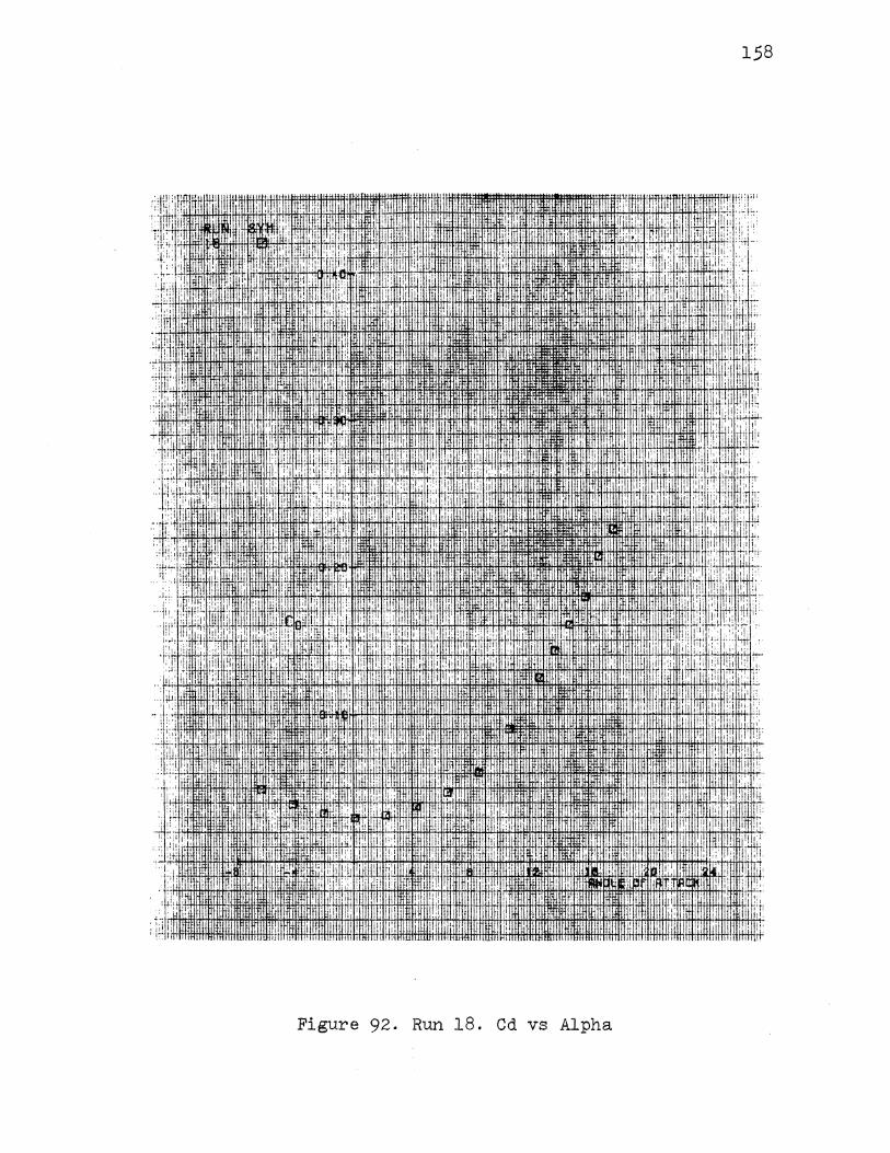
158
~~i: I · , . . . ,
. • :U ·UHlii!ITfllH rlnllnHJt!ll
',' Jill! I 111111111 ,:
1,'
1!1: ll!IDI'll
· \ililll rnrlmrrrnm mmlffllltn: ~~· 1\Hllllltll ILLIHIIIH111. lfllllll Tf
Figure 92. Run 18. Cd vs Alpha
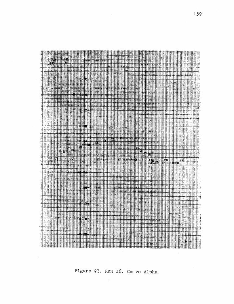
159
1Hl'i't . IH'I· I
!i I I n
: ! . II
•·:•
I ,il
I I II I I
• :! '
1 i
It: ! . [iJ; ·' j: '!··:: • I !J j...[.!. • I
;'1 :.1 I h J:c+ll•; :: i 1
1 I i'ili!!
'!'
: I' 'i I
I' ,, I I
'""" llllllll fill II lUI ""' tl.tll
Figure 93. Run 18. Cm vs Alpha
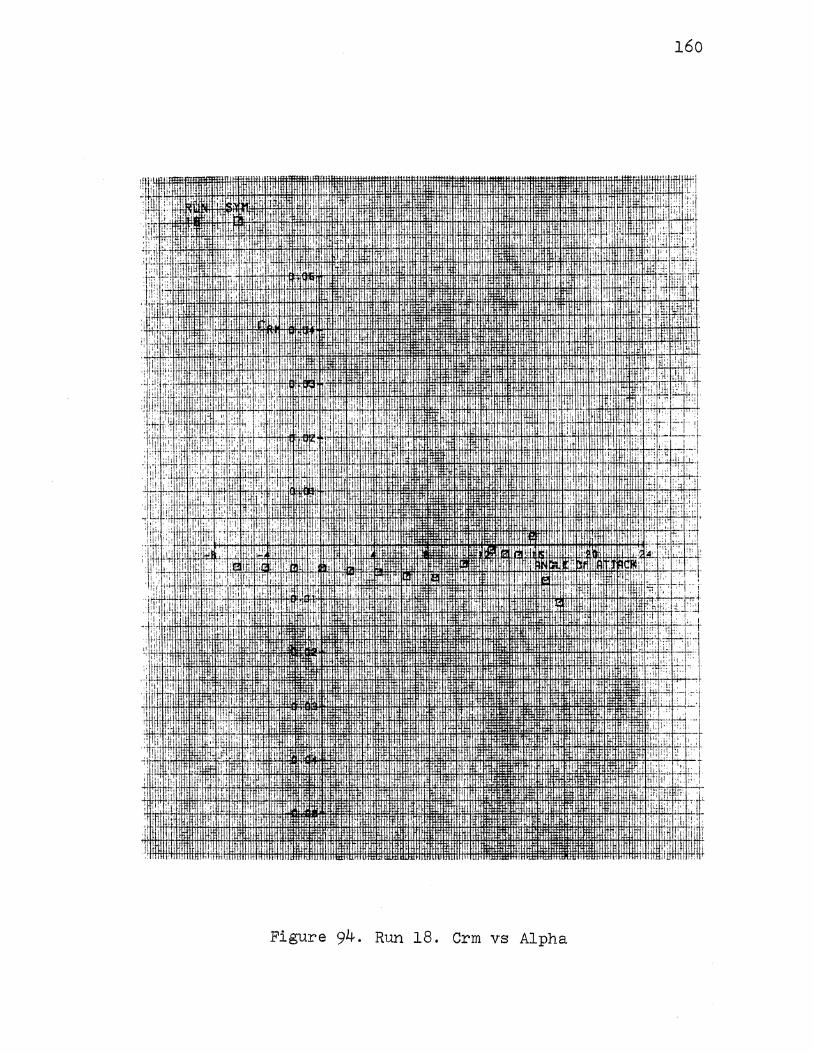
160
' "" ' :r. rm:.. 1:PIIl'i!
.hj I, ii •I. I
I I, ,, I
' ,.
· L; 11 11t1 · .•• •:v: ·: ,,, ' ... •• . ,I ~: '1: I .·i I' •:L: ''"IF l.:j
.> H1J:lti+Ht+4f!+\l+l+t+Hl#ll:!±ll:!l . . , . · , . · , : . ".1•.·<1 1', .':.' :::·' ,,, ' . . . .... ~·· . .•. ,I I . I~· ~;l~.-:;· I.'L:
. ,1' l.i .; '.! ,. Ill' :!Ill"· : , .,· ' ! i:, ',: tl!j ::u ,·, I ! I ·r,. 1! : ·.
· ' ! ' , : , 1 ' 11 ,. ~ .• . • ·• • ' :.. . : : r : I , . 1 1 , ! 1 ll ; : : . · · ·
:r t;,; :_, 1::: : :. 1:1 1 1 1 , ttl~ , · ·· . i j::·,· . I i:!, 1, ·:: I i ·. I t~f:l H>k1·1::
:I: ' :!' l' :: I ' . I
Figure 94. Run 18. Crm vs Alpha
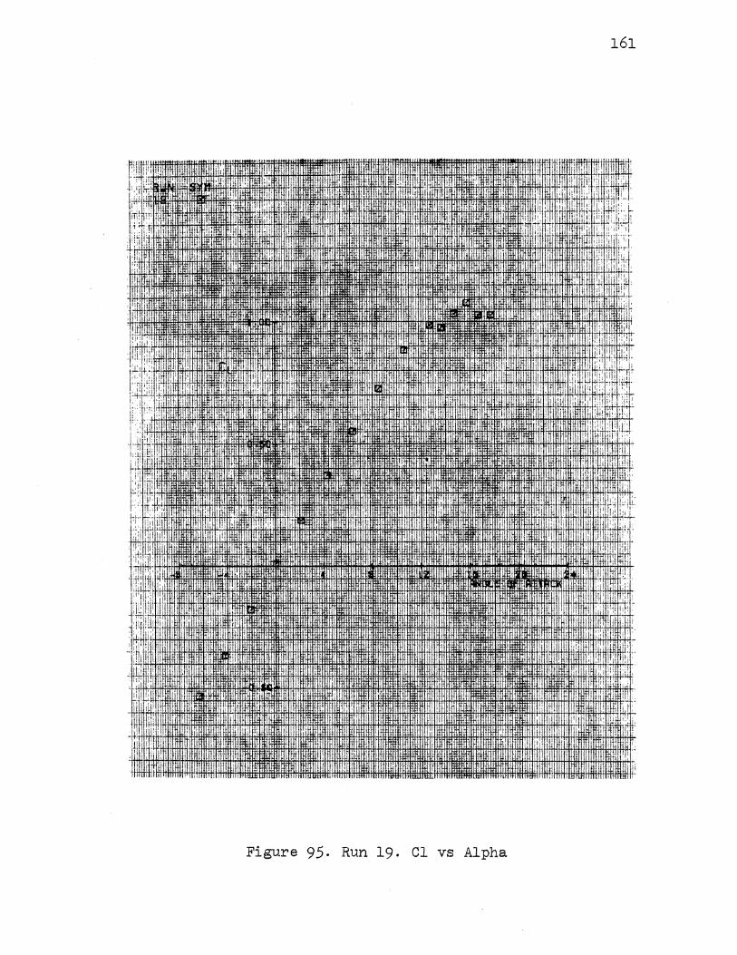
161
::l I i1i I I' n! @,' I ll1li I
;I ' li i ,:,(.
I,: l:lli ' l Ht: I i ,.
' ,' I : ,, ~~4· i . !!"! .; I
" l!i IIi ~'-. ' fl~ I' I: ~ i ,i lj
jil 't i:·i. :1: I
: ii" I I j; I; ·;:1
I ,; · ,' i·r·
. ~II
1.1 I ' I
I. : • !~:
w.rL I 1:11 I 'I ''.
I • ' II .. ;W. •I ,.I
I' I P1 :
' .11 ! •• !i .I
I 'I
.. - ' :il '!• : ,, ' I '
:ill' llj 1_1 I I I il lit'. I .I : 1:J. !P; , ! I I II
'likf I - 111 i;,: ::! '! J I I '\ C ' i I
~~~8U :[I I; .. I I '!; .T < I I· i ! -c ::: . i ' II ! l " .II :!i ;: : ~~~I
'i' , •.•. ;:I ' .I
1; til I E!·· i'l II
II. l[ !il' I I : l: i11. · II • J I I fH '.
' ' '1: I.:_ I:;.!!·. ilTH1
'1 . . ftlt!H'fU.
• I .!·:
I
I:,
. ! IJimliJt ill: I 1!•
W~~:l .,
f'·'. I!,· .:ilL
h· .. 1.· I I i I' ;,!
'I I !=tm I'· 'I ' ~ '
:!':1 I :t ! ~ ' I I'' ;'!I • I. 'I 1,, 'I. I '
. i I . . I ,I •
. :! I 1f : ;,
i' t !il.lil. I[ ~~~~~~ II it i:!i ;t. i~ ' ,,, I tl:ltttU
II I m:rm· rumH HJI i· ' iillli i I ·. I l!j
..
ill ilil I I I
1"1' ,,
I I i,, I
I llml.J.H I ' '' I ' I ·lilt.m=IH! h ::f l#h . I : :,11
,I i .' ffi!
I . ·' ' I
' I
; I~~ I l I I i II I' . ' ~ : I I•
l ' 'II!. 1- I
· lttlllmTIDHMIIIII1llrrlli!IHIIT+l1 . IIHf!lll rHHHI I ~;1 I
tlllllltnii!IIIINiltliiiHIIIlifiN- !!ttn!H 11m I !i lilllffll\11 \li;111111: 1 llllllttt:ttJ.tll.tllltU ~lltJtrt =· EEl
Figure 95. Run 19. Cl vs Alpha

162
::1 ''I 'I. ·'it ·i'' II i"
~·;~I ii I if'
:r:, '" .I
.,, I II ~ f1 i ! 1 I :,.
:.,!. ;U i!H ~. JJFFrflll
:·:i'l!:l. ·'· I .\l ,,; !
I ··!,!1 H '.1 ,, :
:;:;: ! ::1·'. '!i
:i:,·; I I, •'r 1
i;' jl ;j'i." I i IHffit ·.
I~.
Figure 96. Run 19. Cd vs Alpha
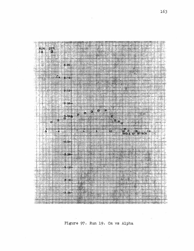
163
li:l!' UlU 11 1IT1!IT· 11.11: !!l:i1 1' Hill
flT: : I ..
iii' liil! IUI!ill' 'llHIHIIiii·HHIIIIHilllrlllfi!IIIUnTH~JitHHII IIIIHnlHIIil!llll 'lilllllllli'lil /!' UJ.JilllT lilt!· ltlllt'llillllllll tlllitt: Hlllll iflillliHiflll! Iii ""' , .
'i: ii !li ;,
1+!Hil1tllillfiiHllllliJH!JiiWHilY1UJffffl1lll iHHttiHTUIIIIIil ··i:l!illlff\Jn.: :i 1 ::; 1 ii
Figure 97. Run 19. Cm vs Alpha
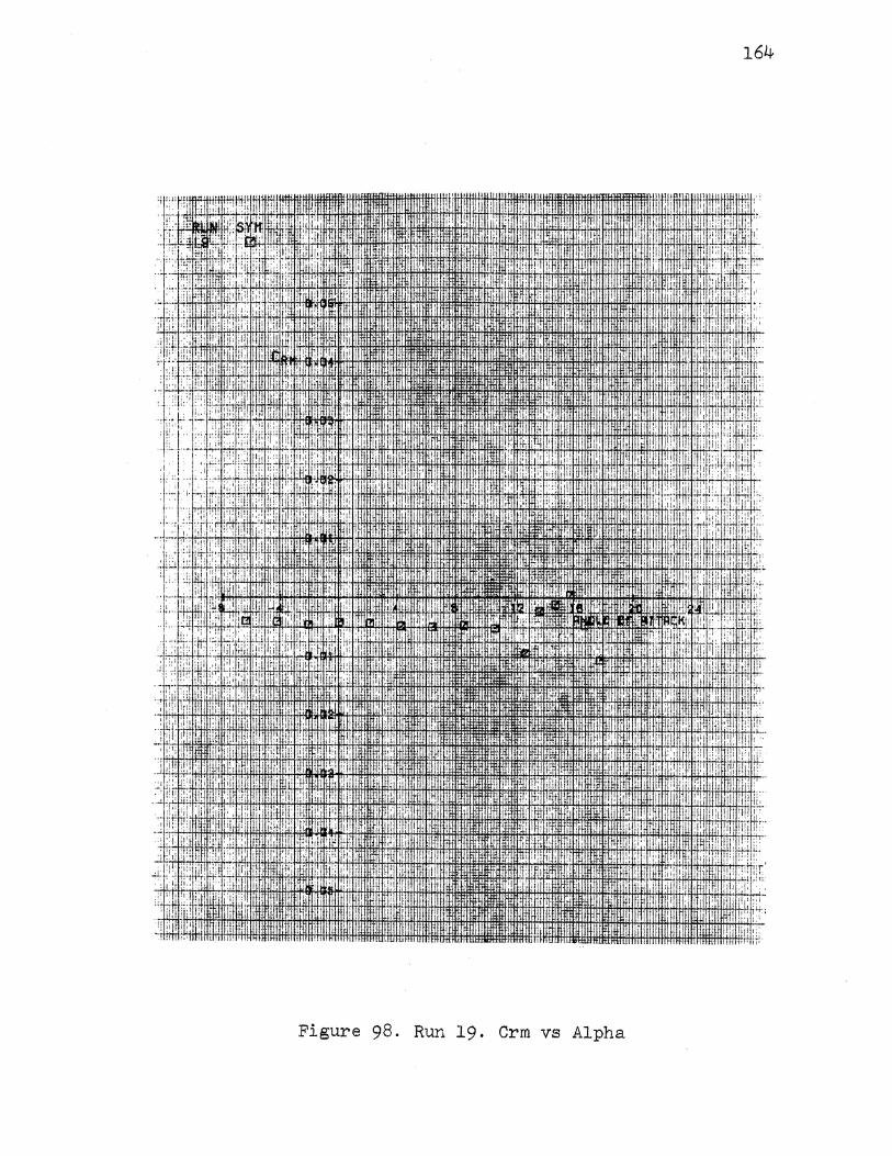
: i! ,I. t I ill I ,.,
i ,., : iJI: '!I ii
,I tl! I I ··: 1: I '• !'I I
' i I, ; I I
' I '• I '· I L ~ 1·.!
~~ , i; , :'I ill' .. '
. . ! : r l lj ~j ' 1;,
I
. ·if~! I ,,
! ~ : ' . : ' ' Ji .:: 'i II:• I
,,'
. ..'J. ~,; ii··
.J: 'IIi :!:' !'
,: '· ... i:' '
;; ,, i::i :
:u II;·
I! !'I tJi I, fli ~ ' I
,, "
II I·! I! l
1·, I I •I I '~''' li·! I' 1,:,
'i I ! I
,, , ..
I II. IIi
I' 1'1, I I!;
'
I
I I
:I,. I l
I'!
.. , I I I i
,., ,,
Figure 98. Run 19. Crm vs Alpha
164
'r !.
:!:
iii ,,,
!i
!!'j !II .
:u· j! I : ~ ! ' :;'oil: II' i! ·:;,
!II
I .I •!.
i i i
; i ~ I·
i!: !II !i I il I ,
I ·! ·:
·L 'i! ; I ! I ~ I 11 ! : !
:II ,,j!t! li' . Uli !'
I 'J:;
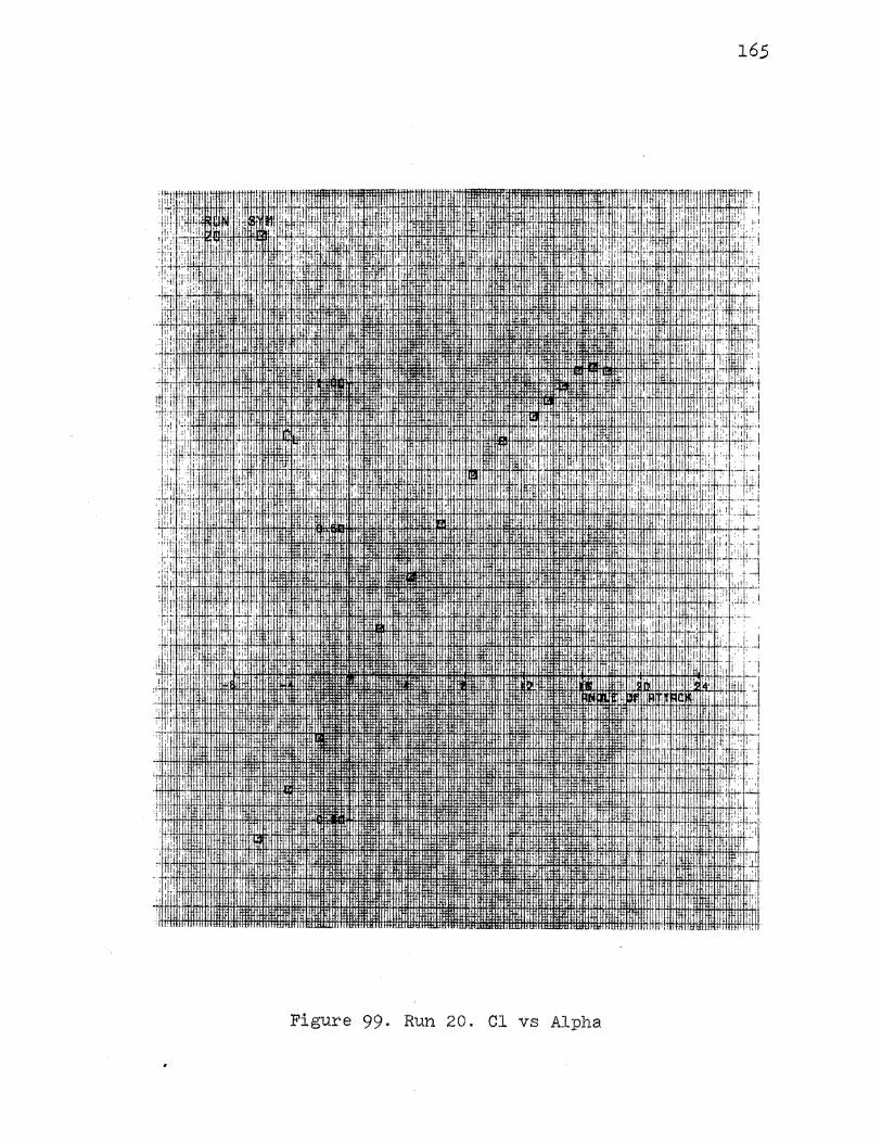
165
! I .(" I : ,, •I·
,li' 11'·
I
i ill I !
·" I I• I ! : '" i !.! :I I
I ' ' ,:
! ': :' I I
I
i I
Figure 99. Run 20. Cl vs Alpha
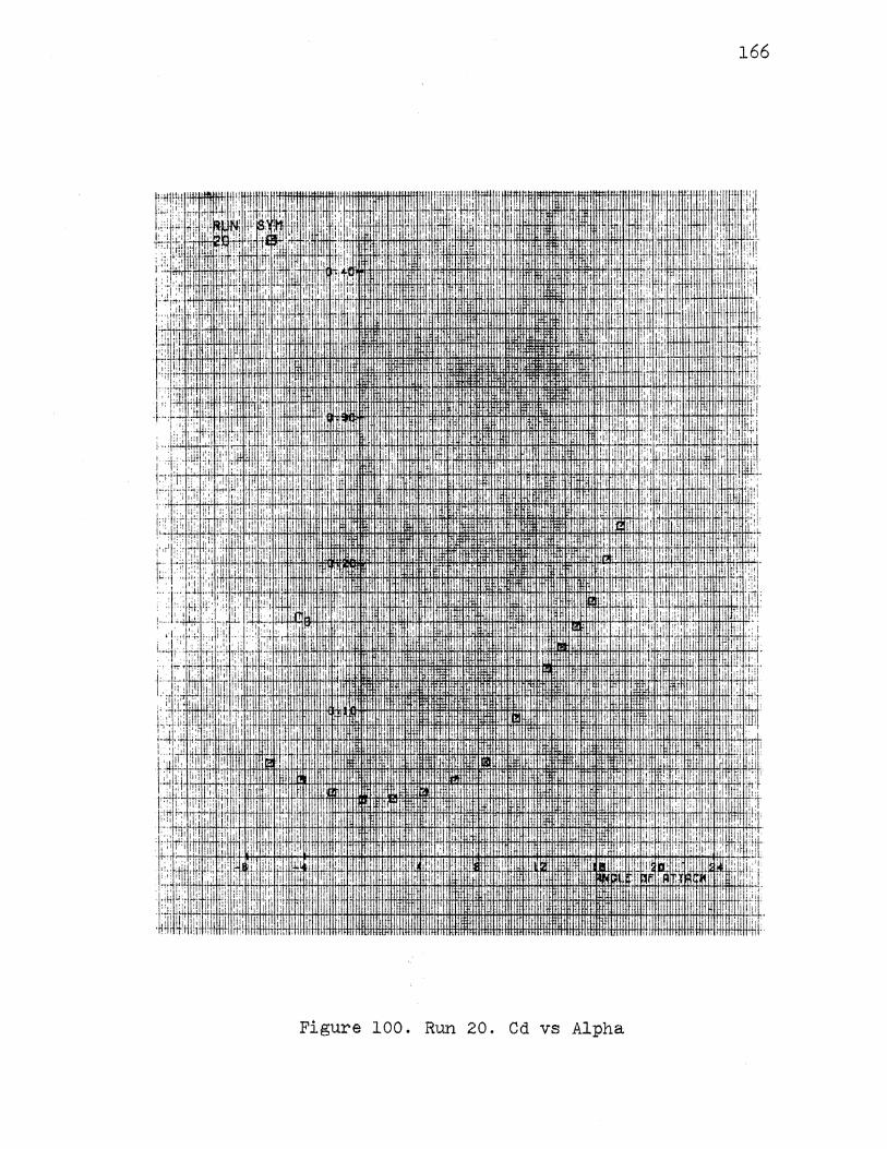
166
tl . ~t:i !:
I I , ,IIIII!
. , ! ' tst;~!'11tlMLLL!IIIUI )l~ ""fl+ltlfHfFf~rHHI+IHi+ltlt!~; ·f~ ,', 1++1. iH•'*t· +hlH:!i :II: 'liT
· :~ :i :,; lmutll~t:~: m: lllllllllilllllllt~m1tlll~!! I . r;;'i · : 'r,mnm ;!· ,B ·
.. ~ ! il 'I'•
I I
• : :~ . , . "' , I nmnH i I
''TI : ~ !
·.' •I; ''i· ,, : J i; [ ::! '1 i 44i+d1 i !+11 t!+t!+Hf' 't!H++HAA+H+fi*FH+HHTI*I+HHH:Htti:\tl'*l:l+!
;·~,v-~:. ,(·::: ,;;:,.
,nil'''''''''l;i,,l,,t,,um~~~~~HIIll !llll~!!!!l!!lltii!~!!~!~J-!!!11(,,1Ltll
! .:1 I
,. , I ,[
t1l.
,,
d "·'' :I il ,I
il E'. 'I' 'I I I I
I• q:r , ..
I II
·il ~~ .11 i; 1 ,lii
i':
1.!: I' ;: ij 111 I jl;, ! II
c;.. !d I I' ,!
l!:i lj
li· I
lliiJ. tL ., ITif 'I I !~ ~I I i
,. I
II I ,,: I; i; ii~: '
I· i i 1!!:: , I I'
I I I i ·I
. 'I
I I'
:.
::' .
I! ~.: !
I :·
lllttntllll!IHIIIIII111HH111 -1!1111!1 il1i Hflllllllli\!illilililllllm iiH!lJJ Iii
11:1111111 IIUIII1JitltiUII.IIIIIItll llllllllrllllll I II ·I .
Figure 100. Run 20. Cd vs Alpha
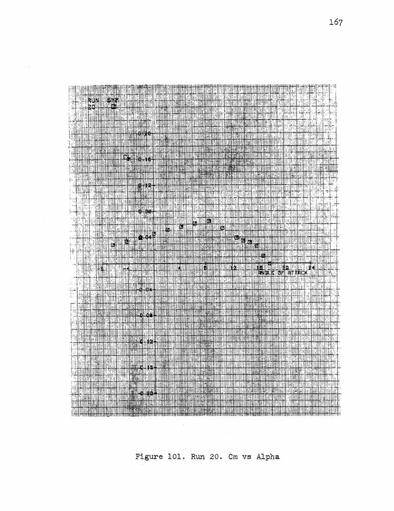
:·:i li: i 1i
t~r: II!;'
1'1 !' I ' :'
~ I
:~ I IJ. I ill I Ell
1·~
f;, i[l :•,'
I,
I !:;· I lji ':1
' : I 1:
li 'I I.
I
i
,I
i! ,j ! 11·
I ' ,, "! I ,,•
Figure 101. Run 20. Cm vs Alpha
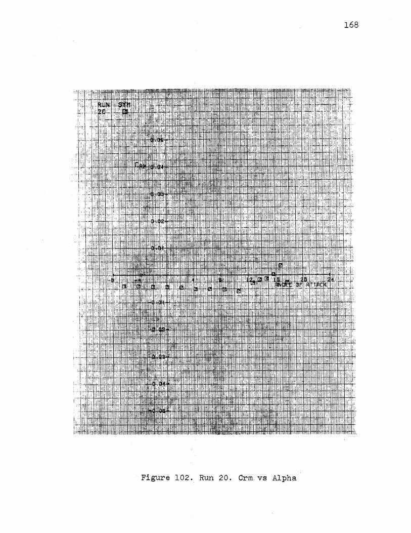
168
' J.i.LrJ.! I
! 11 ! I:
Figure 102. Run 20. Crm vs Alpha
VITA~ Gary L.. ~:::repr:s
Candidate fer the Degree of
M~ster of Science
Thesis: AN AILERON DESIGN TO COUNTER ADVERSE YAW
Major Field: Mechanical Engineering
Personal Data= Born in Bristow~ Oklahoma, October 18~ 1948~ the son of Bill J. and Edna v. Kreps. Marri~d to Judy A. Charlson on October 20, 1973.
Education= Graduated from College High School, Bartlesville, Oklahoma in May 1966; received a Bachelor of Science degree in Mechanic~l and Aerospace Engineering from Oklahoma State University in July 1970; completed the requirements for the Master of Science degree at Oklahoma State University in July 1985.