Oscillatory wave fronts in chains of coupled nonlinear oscillators
Upload
grenoble-inpCategory
view
0download
0
L-1163
Multiple scale structure of non wetting fluid invasion frontsin 3D model porous media
E. Clément, C. Baudet and J. P. Hulin
Laboratoire d’Hydrodynamique et de Mécanique Physique, E.S.P.C.I., 10 rue Vauquelin,75231 Paris Cedex 05, France
(Re.Cu le 17 juillet 1985, accepte sous forme dejinitive le 18 octobre 1985)
Résumé. 2014 Nous présentons des résultats de mesures expérimèntales de la structure de frontsd’invasion obtenus par une injection verticale lente de métal de Wood non mouillant dans un massifde verre pilé non consolidé. Nous analysons la géométrie de coupes du front d’invasion perpendi-culaires et parallèles à la direction de l’écoulement. La structure des coupes perpendiculaires est auto-homothétique dans une gamme d’échelles de longueur de 1 à 20 avec une dimension fractale de 1,65.Les profils de saturation obtenus à partir de coupes parallèles à l’écoulement sont qualitativementen accord avec les modèles de percolation. Nous discutons différentes prédictions théoriques sur lagéométrie des coupes perpendiculaires à l’écoulement.
Abstract. 2014 We report experimental measurements on the structure of invasion fronts obtainedby slow vertical injection of liquid, non wetting, Wood metal into non consolidated crushed glass.The geometry of plane cuts of the invasion front both parallel and perpendicular to the flow directionis analysed. The structure of perpendicular cuts is self similar in a length scale range of 1 to 20 with afractal dimension 1.65. Saturation profiles measured from parallel cuts are in qualitative agreementwith invasion percolation models. Possible theoretical predictions for the geometry of horizontal cutsare discussed.
J. Physique Lett. 46 (1985) L-1163 - L-1171 1 15 DECEMBRE 1985,
Classification
Physics Abstracts47.55M
1. Introduction.
2 phase flow in porous media is a subject of large present interest because of its practical appli-cations in the oil industry (oil-water flows in oil reservoirs) and in hydrogeology (air-water flowsin partly saturated soils).While this topic has greatly benefited from recent theoretical developments of scaling approa-
ches [ 1-4] to the physics of porous media, very few experiments were performed in this perspective.Lenormand [5, 6] has analysed the low velocity invasion of 2D horizontal micromodels by a
non wetting fluid (drainage). He showed that a minimum threshold injection pressure is necessaryto invade the bulk of the micromodel (breakthrough point). At this threshold, the invading fluidvolume has a fractal geometry analogous to a 2D bond percolation cluster. He measured a fractaldimension df ~--- 1.80-1.83 in excellent agreement with « invasion percolation » numerical simu-lations [3, 9] taking into account trapping effects for an incompressible displaced wetting fluid.For classical percolation with no trapping effects, df is slightly higher (- 1.89 in 2D).
Article published online by EDP Sciences and available at http://dx.doi.org/10.1051/jphyslet:0198500460240116300
L-1164 JOURNAL DE PHYSIQUE - LETTRES
Recently, measurements on a non consolidated glass column initially saturated with a matchedindex water-ZnCl2 solution and emptying under gravity have been reported by Jacquin [7].
In this Letter, we present experimental results obtained on a 3D model system (non consoli-dated crushed glass) slowly invaded by a low melting point, non wetting, liquid alloy (Woodmetal) used as a liquid phase (Fig. 1). After the injection, the alloy is solidified and plane cuts ofthe invasion front are performed both parallel (Fig. 2) and perpendicular (Fig. 3) to the flow.We analyse both the fluid saturation profile and the cut geometry in the light of the invasion
percolation models. These describe well low velocity injections when viscous forces can beneglected; however, we have to take into account in addition the effect of hydrostatic pressuregradients (the injection is vertical).The first experiments have been performed by one of us (E. C.) [8] together with Jacquin (I. F. P.
laboratories) who introduced us to the technique of Wood metal injection also developed byBourbie and Zinzner (I.F.P.). Subsequent samples such as that of figure 2 were obtained in ourlaboratory.
2. Experimental procedure and set-up (Fig. 1 ).2. 1 INJECTED FLUID. - Wood metal has been chosen because it is a low melting point alloy(r~ ~ 70 ~C). It can be slowly solidified after the injection in the liquid state in order to examinethe invasion front structure. Wood metal, like mercury, also does not wet the glass : thereforeparasitic effects due to poorly defined wetting characterics are minimized (particularly while thealloy moves into the material). However, the high Wood metal density induces large gravitationaleffects which must be taken into account
2.2 POROUS MATERIAL. - We inject the liquid Wood metal into non consolidated crushed glass :this allows us to remove the glass grains from the non invaded parts after the alloy solidificationin order to observe the invasion front. The granulometry is carefully selected between mesh sizesof 200 and 225 ~m in order to avoid stratification while filling the tube.
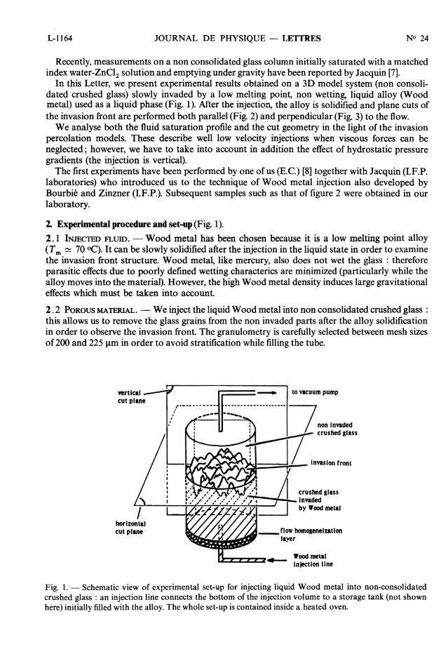
Fig. 1. - Schematic view of experimental set-up for injecting liquid Wood metal into non-consolidatedcrushed glass : an injection line connects the bottom of the injection volume to a storage tank (not shownhere) initially filled with the alloy. The whole set-up is contained inside a-heated oven.
L-1165INVASION FRONTS IN 3D POROUS MEDIA
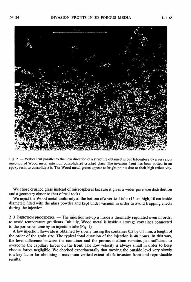
Fig. 2. - Vertical cut parallel to the flow direction of a structure obtained in our laboratory by a very slowinjection of Wood metal into non consolidated crushed glass. The invasion front has been potted in anepoxy resin to consolidate it. The Wood metal grains appear as bright points due to their high reflectivity.
We chose crushed glass instead of microspheres because it gives a wider pore size distributionand a geometry closer to that of real rocks.We inject the Wood metal uniformly at the bottom of a vertical tube (15 cm high, 10 cm inside
diameter) filled with the glass powder and kept under vacuum in order to avoid trapping effectsduring the injection.
2. 3 INJECTION PROCEDURE. - The injection set-up is inside a thermally regulated oven in orderto avoid temperature gradients. Initially, Wood metal is inside a storage container connectedto the porous volume by an injection tube (Fig. 1).A low injection flow-rate is obtained by slowly raising the container 0.5 by 0.5 mm, a length of
the order of the grain size. The typical total duration of the injection is 48 hours. In this way,the level difference between the container and the porous medium remains just sufficient toovercome the capillary forces on the front. The flow velocity is always small in order to keepviscous forces negligible. We checked experimentally that moving the outside level very slowlyis a key factor for obtaining a maximum vertical extent of tlie invasion front and reproducibleresults.
L-1166 JOURNAL DE PHYSIQUE - LETTRES
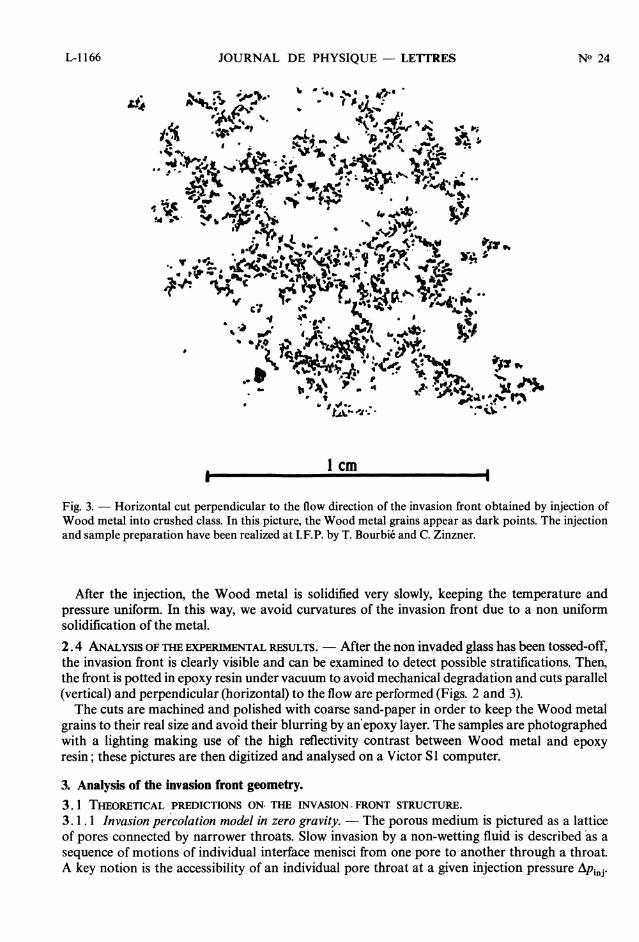
Fig. 3. - Horizontal cut perpendicular to the flow direction of the invasion front obtained by injection ofWood metal into crushed class. In this picture, the Wood metal grains appear as dark points. The injectionand sample preparation have been realized at I.F.P. by T. Bourbie and C. Zinzner.
After the injection, the Wood metal is solidified very slowly, keeping the temperature andpressure uniform. In this way, we avoid curvatures of the invasion front due to a non uniformsolidification of the metal.
2.4 ANALYSIS OF THE EXPERIMENTAL RESULTS. - After the non invaded glass has been tossed-off,the invasion front is clearly visible and can be examined to detect possible stratifications. Then,the front is potted in epoxy resin under vacuum to avoid mechanical degradation and cuts parallel(vertical) and perpendicular (horizontal) to the flow are performed (Figs. 2 and 3).The cuts are machined and polished with coarse sand-paper in order to keep the Wood metal
grains to their real size and avoid their blurring by an’epoxy layer. The samples are photographedwith a lighting making use of the high reflectivity contrast between Wood metal and epoxyresin; these pictures are then digitized and analysed on a Victor Sl computer.
3. Analysis of the invasion front geometry.3. 1 THEORETICAL PREDICTIONS ON THE INVASION FRONT STRUCTURE.3.1.1 Invasion percolation model in zero gravity. - The porous medium is pictured as a latticeof pores connected by narrower throats. Slow invasion by a non-wetting fluid is described as asequence of motions of individual interface menisci from one pore to another through a throat.A key notion is the accessibility of an individual pore throat at a given injection pressure A~j.
L-1167INVASION FRONTS IN 3D POROUS MEDIA
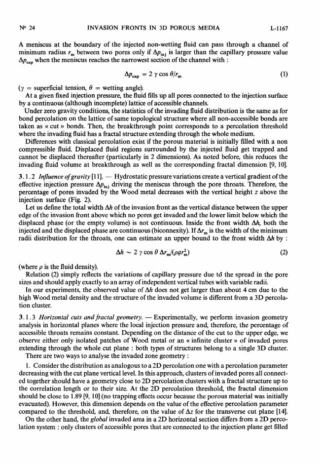
A meniscus at the boundary of the injected non-wetting fluid can pass through a channel ofminimum radius rm between two pores only if Opin3 is larger than the capillary pressure valueÂPcap when the meniscus reaches the narrowest section of the channel with :
(y = superficial tension, 0 = wetting angle).At a given fixed injection pressure, the fluid fills up all pores connected to the injection surface
by a continuous (although incomplete) lattice of accessible channels.Under zero gravity conditions, the statistics of the invading fluid distribution is the same as for
bond percolation on the lattice of same topological structure where all non-accessible bonds aretaken as « cut » bonds. Then, the breakthrough point corresponds to a percolation thresholdwhere the invading fluid has a fractal structure extending through the whole medium.
Differences with classical percolation exist if the porous material is initially filled with a noncompressible fluid Displaced fluid regions surrounded by the injected fluid get trapped andcannot be displaced thereafter (particularly in 2 dimensions). As noted before, this reduces theinvading fluid volume at breakthrough as well as the corresponding fractal dimension [9, 10].
3.1. 2 Influence of gravity [11]. - Hydrostatic pressure variations create a vertical gradient of theeffective injection pressure APinj driving the meniscus through the pore throats. Therefore, thepercentage of pores invaded by the Wood metal decreases with the vertical height z above theinjection surface (Fig. 2).
Let us define the total width Ah of the invasion front as the vertical distance between the upperedge of the invasion front above which no pores get invaded and the lower limit below which thedisplaced phase (or the empty volume) is not continuous. Inside the front width AA, both theinjected and the displaced phase are continuous (biconnexity). If Arm is the width of the minimumradii distribution for the throats, one can estimate an upper bound to the front width Ah by :
(where p is the fluid density).Relation (2) simply reflects the variations of capillary pressure due td the spread in the pore
sizes and should apply exactly to an array of independent vertical tubes with variable radii.In our experiments, the observed value of Ah does not get larger than about 4 cm due to the
high Wood metal density and the structure of the invaded volume is different from a 3D percola-tion cluster.
3.1. 3 Horizontal cuts and fractal geometry. - Experimentally, we perform invasion geometryanalysis in horizontal planes where the local injection pressure and, therefore, the percentage ofaccessible throats remains constant. Depending on the distance of the cut to the upper edge, weobserve either only isolated patches of Wood metal or an « infinite cluster » of invaded poresextending through the whole cut plane : both types of structures belong to a single 3D cluster.There are two ways to analyse the invaded zone geometry :1. Consider the distribution as analogous to a 2D percolation one with a percolation parameter
decreasing with the cut plane vertical level. In this approach, clusters of invaded pores all connect-ed together should have a geometry close to 2D percolation clusters with a fractal structure up tothe correlation length or to their size. At the 2D percolation threshold, the fractal dimensionshould be close to 1.89 [9, 10] (no trapping effects occur because the porous material was initiallyevacuated). However, this dimension depends on the value of the effective percolation parametercompared to the threshold, and, therefore, on the value ofAz for the transverse cut plane [14].On the other hand, the global invaded area in a 2D horizontal section differs from a 2D perco-
lation system : only clusters of accessible pores that are connected to the injection plane get filled
L-1168 JOURNAL DE PHYSIQUE - LETTRES
with metal. In addition, these clusters are not located at random : spatial correlations occur due toconnections in the third dimension.
2. In the second approach, the cut is considered as a section of an infinite, locally isotropic, 3Dcluster. If we assume that the percolation model is valid, this 3D cluster has a fractal dimensiondf 3D 2.5 at the percolation threshold. Then the global cut structure including all finite andinfinite invaded zones should have a fractal dimension df = d - 1 ~ 1.5.
Experimentally, it is not possible to determine whether a set of invaded pores belong to the samecluster since the connecting channels are indeed generally hidden by the solid matrix. Hence, wehave chosen to analyse the distribution of all pores invaded by Wood metal in the section withoutattempting to determine whether they are located on a same 2D cluster. We can therefore comparethe results only to the predictions from the second approach discussed above.
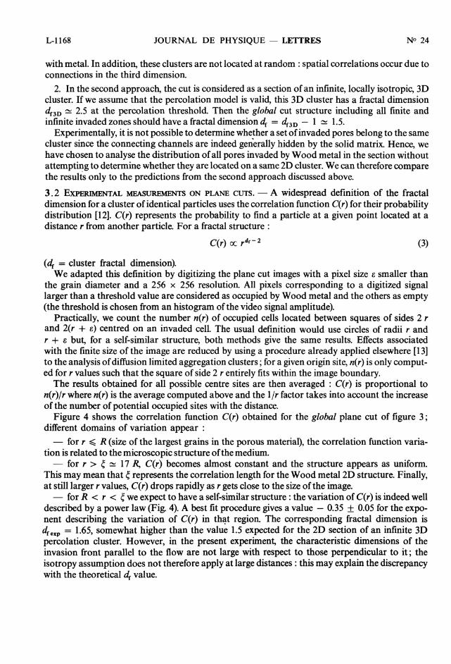
3.2 EXPERIMENTAL MEASUREMENTS ON PLANE CUTS. - A widespread definition of the fractaldimension for a cluster of identical particles uses the correlation function C(r) for their probabilitydistribution [12]. C(r) represents the probability to find a particle at a given point located at adistance r from another particle. For a fractal structure :
(df = cluster fractal dimension).We adapted this definition by digitizing the plane cut images with a pixel size e smaller than
the grain diameter and a 256 x 256 resolution. All pixels corresponding to a digitized signallarger than a threshold value are considered as occupied by Wood metal and the others as empty(the threshold is chosen from an histogram of the video signal amplitude).
Practically, we count the number n(r) of occupied cells located between squares of sides 2 rand 2(r + s) centred on an invaded cell. The usual definition would use circles of radii r andr + e but, for a self-similar structure, both methods give the same results. Effects associatedwith the finite size of the image are reduced by using a procedure already applied elsewhere [13]to the analysis of diffusion limited aggregation clusters; for a given origin site, n(r) is only comput-ed for r values such that the square of side 2 r entirely fits within the image boundary.The results obtained for all possible centre sites are then averaged : C(r) is proportional to
n(r)lr where n(r) is the average computed above and the 1 /r factor takes into account the increaseof the number of potential occupied sites with the distance.
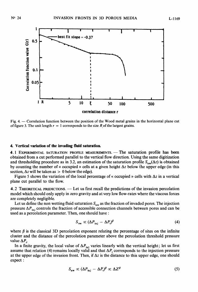
Figure 4 shows the correlation function C(r) obtained for the global plane cut of figure 3 ;different domains of variation appear :- for r R (size of the largest grains in the porous material), the correlation function varia-
tion is related to the microscopic structure of the medium.- fbrr>~~17~ C(r) becomes almost constant and the structure appears as uniform.
This may mean that ~ represents the correlation length for the Wood metal 2D structure. Finally,at still larger r values, C(r) drops rapidly as r gets close to the size of the image.- for R r ~ we expect to have a self-similar structure : the variation of C(r) is indeed well
described by a power law (Fig. 4). A best fit procedure gives a value - 0.35 ± 0.05 for the expo-nent describing the variation of C(r) in that region. The corresponding fractal dimension isdf exp = 1.65, somewhat higher than the value 1.5 expected for the 2D section of an infinite 3Dpercolation cluster. However, in the present experiment, the characteristic dimensions of theinvasion front parallel to the flow are not large with respect to those perpendicular to it; theisotropy assumption does not therefore apply at large distances : this may explain the discrepancywith the theoretical df value.
L-1169INVASION FRONTS IN 3D POROUS MEDIA
Fig. 4. - Correlation function between the position of the Wood metal grains in the horizontal plane cutof figure 3. The unit length r = 1 corresponds to the size R- of the largest grains.
4. Vertical variation of the invading fluid saturation.
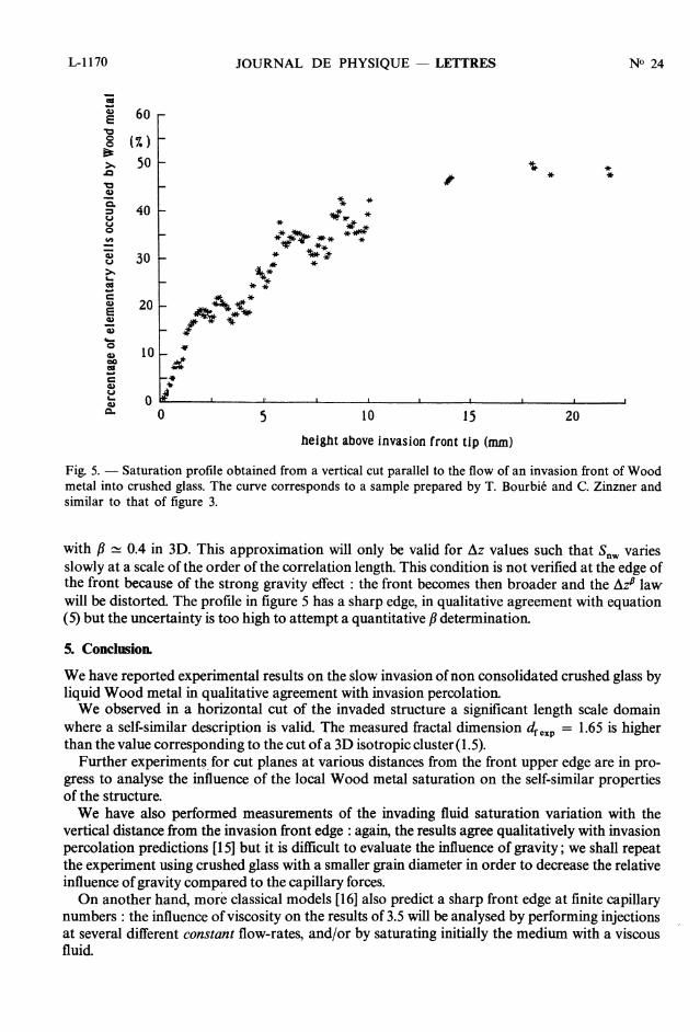
4.1 EXPERIMENTAL SATURATION PROFILE MEASUREMENTS. The saturation profile has beenobtained from a cut performed parallel to the vertical flow direction. Using the same digitizationand thresholding procedure as in 3.2, an estimation of the saturation profile Snw(L1z) is obtainedby counting the number of « occupied » cells at a given height Az below the upper edge (in thissection, Az will be taken as > 0 below the edge).
Figure 5 shows the variation of the local percentage of « occupied » cells with Az in a verticalplane cut parallel to the flow.
4.2 THEORETICAL PREDICTIONS. - Let us first recall the predictions of the invasion percolationmodel which should only apply in zero gravity and at very low flow-rates where the viscous forcesare completely negligible.
Let us define the non wetting fluid saturation Snw as the fraction of invaded pores. The injectionpressure åPinj controls the fraction of accessible connection channels between pores and can beused as a percolation parameter. Then, one should have :
where p is the classical 3D percolation exponent relating the percentage of sites on the infinitecluster and the distance of the percolation parameter above the percolation threshold pressurevalue OPt.
In a finite gravity, the local value of dPin~ varies linearly with the vertical height; let us firstassume that relation (4) remains locally valid and that ePt corresponds to the injection pressureat the upper edge of the invasion front. Then, ifAz is the distance to this upper edge, one shouldexpect :
L-1170 JOURNAL DE PHYSIQUE - LETTRES
height above invasion front tip (mm)
Fig. 5. - Saturation profile obtained from a vertical cut parallel to the flow of an invasion front of Woodmetal into crushed glass. The curve corresponds to a sample prepared by T. Bourbie and C. Zinzner andsimilar to that of figure 3.
with ~ ~ 0.4 in 3D. This approximation will only be valid for Az values such that S.,,,, variesslowly at a scale of the order of the correlation length. This condition is not verified at the edge ofthe front because of the strong gravity effect : the front becomes then broader and the Oz~ lawwill be distorted. The profile in figure 5 has a sharp edge, in qualitative agreement with equation(5) but the uncertainty is too high to attempt a quantitative ~ determination.
5. Conclusion.
We have reported experimental results on the slow invasion of non consolidated crushed glass byliquid Wood metal in qualitative agreement with invasion percolation.We observed in a horizontal cut of the invaded structure a significant length scale domain
where a self-similar description is valid. The measured fractal dimension dfexp = 1.65 is higherthan the value corresponding to the cut of a 3D isotropic cluster ( 1. 5).
Further experiments- for cut planes at various distances from the front upper edge are in pro-gress to analyse the influence of the local Wood metal saturation on the self-similar propertiesof the structure.We have also performed measurements of the invading fluid saturation variation with the
vertical distance from the invasion front edge : again, the results agree qualitatively with invasionpercolation predictions [ 15] but it is difficult to evaluate the influence of gravity; we shall repeatthe experiment using crushed glass with a smaller grain diameter in order to decrease the relativeinfluence of gravity compared to the capillary forces.On another hand, more classical models [16] also predict a sharp front edge at finite capillary
numbers : the influence of viscosity on the results of 3.5 will be analysed by performing injectionsat several different constant flow-rates, and/or by saturating initially the medium with a viscousfluid.
L-1171INVASION FRONTS IN 3D POROUS MEDIA
Acknowledgments.
We wish to thank E. Charlaix, E. Guyon and C. Leroy for many fruitful discussions and sug-gestions.We have greatly benefited from the help of T. Bourbie, C. Jacquin and B. Zinzner at I.F.P. who
introduced us to the Wood metal injection techniques and provided us with many data and expe-rimental assistance.One of us (E.C.) has been supported by a grant from the Schlumberger Doll Research Center.
References
[1] DE GENNES, P. G. and GUYON, E., J. Mec. 17 (1978) 403.[2] CHATZIS, J. and DULLIEN, F. A. L., J. Can. Pet. Tech. 97, Jan-Mar (1977).[3] CHANDLER, R., KOPLIK, J., LERMAN, K. and WILLEMSEN, J., J. Fluid Mech. 119 (1982) 249.[4] GUYON, E., HULIN, J. P. and LENORMAND, R., Annales des Mines, special issue « Ecoulements dans les
milieux fissurés », 191, 5-6, 17 (1984) (in French).[5] LENORMAND, R., ZARCONE, C. and SARR, A., J. Fluid Mech. 135 (1983) 337.[6] LENORMAND, R. and ZARCONE, C., to be published in Phys. Rev. Lett. (1985).[7] JACQUIN, C., C.R. Acad. Sci. 300, série II, n° 15 (1985).[8] Groupe Poreux PC, in Proc. de l’Ecole d’Hiver des Houches sur « la Physique de la Matière finement
divisée), M. Daoud ed. (Springer Verlag) 1985.[9] WILKINSON, D. and WILLEMSEN, J., J. Phys. A 16 (1983) 3365.
[10] WILKINSON, D. and BARSONY, M., J. Phys. A 17 (1984) L129.[11] WILKINSON, D., Phys. Rev. A 30 (1984) 520.[12] MANDELBROT, B. B., The Fractal geometry of Nature (Freeman, San Francisco) 1984.[13] WEITZ, D. A. and OLIVEIRA, M., Phys. Rev. Lett. 52 (1984) 1433.[14] STAUFFER, D., Phys. Rep. 54 (1979) 1.[15] WILKINSON, D., in Proc. de l’Ecole d’Hiver des Houches sur « la Physique de la Matière finement
divisée), M. Daoud ed. (Springer Verlag) 1985.[16] DULLIEN, F. A. L., Porous media, fluid transport and pore structure (Academic Press, New York) 1979.
Copyright © 2022 FDOKUMEN