Multipath characterization of indoor power-line networks
11
Reprint Multipath Characterization of Indoor Power Line Networks D. Anastasiadou and Th. Antonakopoulos IEEE Transactions on Power Delivery VOL. 20, NO. 1, JANUARY 2005, pp. 90 - 99 Copyright Notice: This material is presented to ensure timely dissemination of scholarly and technical work. Copyright and all rights therein are retained by authors or by other copyright holders. All persons copying this information are expected to adhere to the terms and constraints invoked by each author's copyright. In most cases, these works may not be reposted or mass reproduced without the explicit permission of the copyright holder.
-
Upload
independent -
Category
Documents
-
view
3 -
download
0
Transcript of Multipath characterization of indoor power-line networks

Reprint
Multipath Characterization of Indoor Power Line Networks
D. Anastasiadou and Th. Antonakopoulos
IEEE Transactions on Power Delivery
VOL. 20, NO. 1, JANUARY 2005, pp. 90 - 99
Copyright Notice: This material is presented to ensure timely dissemination of scholarly and technical work. Copyright and all rights therein are retained by authors or by other copyright holders. All persons copying this information are expected to adhere to the terms and constraints invoked by each author's copyright. In most cases, these works may not be reposted or mass reproduced without the explicit permission of the copyright holder.
90 IEEE TRANSACTIONS ON POWER DELIVERY, VOL. 20, NO. 1, JANUARY 2005
Multipath Characterization ofIndoor Power-Line Networks
Despina Anastasiadou and Theodore Antonakopoulos, Senior Member, IEEE
Abstract—The time- and frequency-varying behavior of an in-door power-line network is the result of variable impedance loadsconnected to its termination points. In fact, any signal transmittedthrough such a communications network is subject to time-varyingmultipath fading. In this paper, an analytical calculation method ispresented, which can be used to determine the multipath compo-nents of any point-to-point channel in the indoor power-line envi-ronment. The method calculates all transmission characteristics ofthe network and, therefore, it can be exploited in the process of de-signing proper transmission algorithms for optimizing system per-formance. The proposed method is applied to an example networkto demonstrate its usefulness in explaining the network’s time-de-pendent behavior and in estimating channel parameters, such assubchannel bandwidth, multipath delay spread, fading conditions,etc.
Index Terms—Delay effects, multipath channels, power trans-mission lines, time-varying channels.
I. INTRODUCTION
THE increasing demand for broadband telecommunicationservices in today’s small-office/home-office (SOHO)
environment has aroused an interest in the exploitation ofalternative communications media [1]. The indoor power gridis a prominent candidate, with its main advantages resultingfrom the utilization of the existing infrastructure and the abun-dance of access points, in the form of ac outlets. However,the development of viable power-line systems for providingtelecommunication services requires statistical modeling ofthe channel’s time-varying behavior based on analytical andexperimental results.
The power-line channel differs considerably in topology,structure, and physical properties from conventional media suchas twisted pair, coaxial, and fiber-optical cables, exhibitingrather hostile characteristics. Initially designed solely for powerdistribution, the power grid is far from being optimized forhigh-speed data transmission. Common causes of impairmentinclude time- and frequency-varying impedances and consid-erable noise due to loads connected to its outlets. As a result,variable levels of signal attenuation are observed on the channel[2]. Various measurement-based and analytical models havebeen proposed in the literature, concerning the communica-
Manuscript received August 18, 2003. Paper no. TPWRD-00430-2003. Thiswork was supported in part by the “Karatheodoris” R&D program of the Uni-versity of Patras. This paper was presented in part at the IEEE InternationalSymposium on Circuits and Systems–ISCAS 2003, Bangkok, Thailand, May2003.
The authors are with the Department of Electrical Engineering andComputer Technology, University of Patras, Patras 26500, Greece (e-mail:[email protected]; [email protected]).
Digital Object Identifier 10.1109/TPWRD.2004.832373
tions properties of the indoor power grid. The most commonapproach considers the channel as a “black box” and extractsa number of system parameters using extensive experimentalresults [3]. Using the same approach, the channel has been ex-amined as a multipath environment, whose characteristics canbe determined using experimental measurements [4]. Statisticalmodeling of the measured additive noise [5] and derivationof the channel’s transfer function have also been attempted.Nevertheless, a widely accepted channel model has not yetbeen presented, since models based on experimental results,obtained on specific topologies and under certain conditions,fail to offer a generally applicable description of the power-linenetwork behavior.
Modeling the power line for high-speed communications canbe aided by analyzing the multipath nature of the power grid,arising from the presence of several branches and impedancemismatches, which cause numerous reflections of the trans-mitted signal. In this paper, we present an algorithm thatperforms analytical calculation of the multipath effect betweenany pair of communicating devices on the indoor power-linenetwork by tracing it back to its physical characteristics, such ascable loss, reflection, and transmission coefficients. Analyticalcalculation of the multipath components in the indoor powergrid is feasible due to its loop-free topology and its boundedcomplexity, thus making it possible to predict the response ofany point-to-point channel, based on information about the net-work’s physical structure, topology, and termination loading.Modeling the power-line channel as a multipath environmentis needed in order to determine the transmission paths thatcontribute to its time- and frequency-variable behavior andto calculate the parameters that define the medium’s com-munications properties, such as the root mean square (rms)delay spread, which indirectly determines the achievable datatransmission rate.
The paper is organized as follows: Section II describesmultipath propagation through the power-line channel andassociates its response to the network’s physical characteris-tics. The algorithm used to perform analytical calculation ofthe multipath signal components is presented in Section III.Finally, Section IV demonstrates the algorithm’s usefulness inestimating important communications parameters by presentingtypical results obtained for an example network.
II. TRANSMISSION IN THE INDOOR POWER-LINE ENVIRONMENT
The variety of loads connected to the network’s terminationpoints (ac outlets) and the presence of several cable branches re-sult in impedance mismatches that cause multipath signal prop-agation in the indoor power-line environment. Even in a homo-
0885-8977/$20.00 © 2005 IEEE

ANASTASIADOU AND ANTONAKOPOULOS: MULTIPATH CHARACTERIZATION OF INDOOR POWER-LINE NETWORKS 91
geneous network constructed using a single type of cable, thetraveling signal suffers a reflection at every point of impedancemismatch, caused by the difference between the cable’s charac-teristic impedance and the termination impedance or even by theparallel connection of a number of cables at a network junctionpoint. As a result, part of the arriving signal is reflected back to-ward its origin, while the remaining signal proceeds in the ini-tial direction. Thus, for a cable with characteristic impedance
, the reflection coefficient at a certain discontinuity, wherean impedance of is connected, expresses the amplitude andphase ratio of the backward propagating (reflected) signal tothe originally arriving signal. The corresponding transmissioncoefficient expresses the analogous for the forward propa-gating signal. These coefficients are calculated using the fol-lowing expressions:
and (1)
Considering a theoretically infinite number of reflections in-side the power-line network, we can deduce that the receivedsignal is composed of infinite distorted replicas of the initiallytransmitted signal, commonly referred to as multipath compo-nents, which differ both in amplitude and phase. Each compo-nent represents the result of propagation through a particularpath, since its amplitude and phase (or delay) depend on thepath’s length and the reflection and transmission coefficientsthat comprise it. However, from a more practical point of view,as the length of a path increases, more reflections occur, the at-tenuation level rises, and, therefore, the path’s contribution tothe overall received signal decreases. As a result, the multipatheffect can be bounded to a finite number of significant paths.Moreover, unlike in the case of a wireless environment, analyt-ical calculation of the multipath effect in an indoor power-linenetwork is feasible, since its topology is relatively limited incomplexity and does not contain loops. Therefore, the responsebetween any pair of communicating devices on the network canbe determined using information about the cable’s transmissionproperties, the network’s topology, and the impedances con-nected to its outlets.
Transmission between the two network termination pointsthat define the communications channel is done through a largenumber of paths. Each path is characterized by a propagationloss factor, a reflection factor, and a delay. The propagation lossfactor and the delay of the th path depend on its lengthand the physical characteristics of the cable, according to thefollowing expressions:
(2)
(3)
where is the path’s length, is the group velocity of propa-gation, and is the propagation constant of the line,defined by the attenuation constant and the phase constant .
The reflection factor of a particular path is the product ofall reflection or transmission coefficients that comprise it. Thefollowing expression corresponds to the total reflection factor
Fig. 1. Point-to-point channel on a power-line network.
of the th path, which consists of not necessarilydifferent discontinuities:
where (4)
Indices and indicate each of the and discontinuitiesincluded in path .
We calculate the channel’s complex impulse response,namely its delay-spread function, based on the general multi-path propagation equations. Considering that transmission ofan impulse through a multipath environment with pathsresults in a train of delayed impulses, we modify the generalexpression to suit the case of an indoor power-line communi-cations network. Thus, the channel’s impulse response can becalculated as the sum of all multipath components according to
(5)
Taking (3) into consideration, the equivalent frequency responsefunction is given by
(6)
The above expression is the frequency-domain ratio of thechannel’s output voltage to the voltage injected into theline by an ideal generator . In the case of apractical power-line network, as shown in Fig. 1, calculationof the transfer function between any two communicating de-vices involves an additional scaling factor, which includes thenonideal characteristics of the transmission system. Since thetransfer function of a point-to-point channel represents the ratioof the steady state voltages measured at the two communicatingends, another scaling factor has to be added, relating the in-coming source voltage to the total voltage measured at thetransmission end , which comprises the injected signal andthe sum of all signal components that are reflected toward thesource. Calculation of the above scaling factors is performed byapplying Kirchhoff’s laws. As a result, we derive the followingexpression for the transfer function of the channel, which is cal-culated as the ratio of the voltages measured at the two commu-nicating termination points:
(7)
92 IEEE TRANSACTIONS ON POWER DELIVERY, VOL. 20, NO. 1, JANUARY 2005
where is the input impedance appearing at the transmissionend in steady state.
III. MULTIPATH COMPONENTS’ CALCULATION ALGORITHM
In order to estimate the transfer function between two com-municating devices on the network, we developed an algorithmthat analytically calculates the multipath channel components.The algorithm uses a set of network description matrices,specifically defined to include all of the necessary informationabout the network’s physical characteristics, topology, andtermination impedances. The algorithm performs the calcu-lation of every reflection and transmission coefficient on thenetwork, along with the input impedances appearing at everynetwork termination. The algorithm identifies a large numberof possible signal paths inside the network and calculatesthe respective lengths, total reflection and propagation factors.It proceeds to select the most significant transmission paths,based on their contribution to the overall output signal power,where is based on their contribution to the overalloutput signal power.
The algorithm’s flexibility is based on a general calculationprocedure that uses a set of network description matrices thatrepresent any network topology along with its loading con-ditions. Additionally, the algorithm takes into considerationthe following conditions, which are always valid in the indoorpower-line environment.
• Each termination point is connected to a single node.• Direct connections between termination points do not
exist.• No loops exist since the network has radial topology.
A. Network Description Matrices
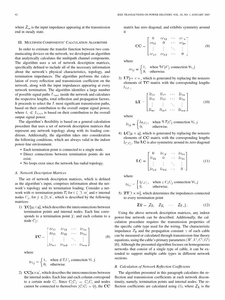
The set of network description matrices, which is definedas the algorithm’s input, comprises information about the net-work’s topology and its termination loading. Consider a net-work with termination points for and internalnodes , for , which is described by the followingmatrices:
1) , which describes the interconnections betweentermination points and internal nodes. Each line corre-sponds to a termination point and each column to anode
......
. . ....
(8)
where
when connectionotherwise
2) , which describes the interconnections betweenthe internal nodes. Each line and each column correspondto a certain node . Since and nodescannot be connected to themselves , the
matrix has zero diagonal, and exhibits symmetry aroundit
......
. . ....
(9)
where
when connectionotherwise
3) , which is generated by replacing the nonzeroelements of matrix with the corresponding lengths
......
. . ....
(10)
where
when connectionotherwise.
4) , which is generated by replacing the nonzeroelements of matrix with the corresponding lengths
. The is also symmetric around its zero diagonal
......
. . ....
(11)
where
when connectionotherwise.
5) , which determines the impedances connectedto every termination point
(12)
Using the above network description matrices, any indoorpower-line network can be described. Additionally, the cal-culation procedure requires the transmission properties ofthe specific cable type used for the wiring. The characteristicimpedance and the propagation constant of each cablecan be measured or calculated through transmission-line theoryequations, using the cable’s primary parameters[6]. Although the presented algorithm focuses on homogeneousnetworks that consist of a single type of cable, it can be ex-tended to support multiple cable types in different networksections.
B. Calculation of Network Reflection Coefficients
The algorithm presented in this paragraph calculates the re-flection and transmission coefficients at each network discon-tinuity, namely, termination points and internal nodes. The re-flection coefficients are calculated using (1), where is the
ANASTASIADOU AND ANTONAKOPOULOS: MULTIPATH CHARACTERIZATION OF INDOOR POWER-LINE NETWORKS 93
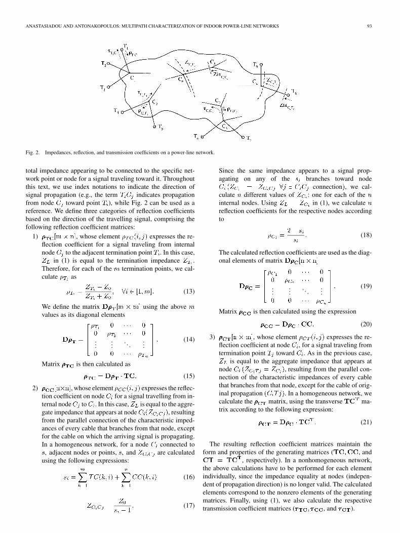
Fig. 2. Impedances, reflection, and transmission coefficients on a power-line network.
total impedance appearing to be connected to the specific net-work point or node for a signal traveling toward it. Throughoutthis text, we use index notations to indicate the direction ofsignal propagation (e.g., the term indicates propagationfrom node toward point ), while Fig. 2 can be used as areference. We define three categories of reflection coefficientsbased on the direction of the travelling signal, comprising thefollowing reflection coefficient matrices:
1) , whose element expresses the re-flection coefficient for a signal traveling from internalnode to the adjacent termination point . In this case,
in (1) is equal to the termination impedance .Therefore, for each of the termination points, we cal-culate as
(13)
We define the matrix using the abovevalues as its diagonal elements
......
. . ....
(14)
Matrix is then calculated as
(15)
2) , whose element expresses the reflec-tion coefficient on node for a signal travelling from in-ternal node to . In this case, is equal to the aggre-gate impedance that appears at node , resultingfrom the parallel connection of the characteristic imped-ances of every cable that branches from that node, exceptfor the cable on which the arriving signal is propagating.In a homogeneous network, for a node connected to
adjacent nodes or points, and are calculatedusing the following expressions:
(16)
(17)
Since the same impedance appears to a signal prop-agating on any of the branches toward node
connection , we cal-culate different values of : one for each of theinternal nodes. Using in (1), we calculatereflection coefficients for the respective nodes accordingto
(18)
The calculated reflection coefficients are used as the diag-onal elements of matrix
......
. . ....
(19)
Matrix is then calculated using the expression
(20)
3) , whose element expresses the re-flection coefficient at node , for a signal traveling fromtermination point toward . As in the previous case,
is equal to the aggregate impedance that appears atnode , resulting from the parallel con-nection of the characteristic impedances of every cablethat branches from that node, except for the cable of orig-inal propagation . In a homogeneous network, wecalculate the matrix, using the transverse ma-trix according to the following expression:
(21)
The resulting reflection coefficient matrices maintain theform and properties of the generating matrices ( , and
, respectively). In a nonhomogeneous network,the above calculations have to be performed for each elementindividually, since the impedance equality at nodes (indepen-dent of propagation direction) is no longer valid. The calculatedelements correspond to the nonzero elements of the generatingmatrices. Finally, using (1), we also calculate the respectivetransmission coefficient matrices ( , and ).

94 IEEE TRANSACTIONS ON POWER DELIVERY, VOL. 20, NO. 1, JANUARY 2005
C. Calculation of Network Input Impedances
In order to estimate the transfer function of any point-to-pointchannel on the network using (7), the input impedances ap-pearing at every termination point have to be determined. Asthese impedances represent the aggregate impedance appearingat the input point at steady state, the calculation procedure re-quires the estimation of the equivalent impedances at every net-work point. Throughout this text, we used the following namingconventions as shown in Fig. 2.
1) is the equivalent impedance at node orpoint with index for a signal traveling toward it fromnode or point with index .
2) is the input impedance of the line sec-tion that connects the nodes or points with indices andwhen entering the section at node or point with index .
The input impedance of a line section terminated by isgiven by
(22)
where is the section length. The following steps describe theprocess used in order to calculate the network impedances:
• Step 1: The process begins by calculating the inputimpedance matrix . Its elementsare calculated using (22) with andthe corresponding length as follows:
(23)
These impedance values form a diagonalmatrix, which is used to generate the requested
matrix, that maintains the form and properties of thematrix, according to
(24)
• Step 2: The process continues with the calculation of theinput and the equivalent impedance matrices of the in-ternal nodes and , respectively.Both matrices maintain the form of the generatingmatrix, but not its symmetry. Elements are cal-culated using (22), with and thecorresponding lengths as follows:
(25)
Equivalent impedance matrix is formed by elements, as the result of the parallel connection of all
input impedances, as they appear to a signal traveling fromtoward every adjacent point or node, except
(26)
Expressions (25) and (26) indicate that the calculation ofelements require elements and vice versa.
Therefore, calculation of the two matrices has to be per-formed simultaneously. Since all required elements are nota priori known, a computationally efficient process wasdeveloped in order to determine the next element that canbe calculated using those already available. A detailed de-scription of this process is given in the Appendix.
• Step 3: This step involves calculation of the equivalentimpedance matrix . We begin by calculatingthe values of using the matrices cal-culated in the previous steps
(27)
Using the values, we calculate by re-placing with and with in (22) as follows:
(28)
These impedance values form a diagonal matrixthat is used to generate the requested
, which maintains the form and properties of the
matrix, according to
(29)
Having calculated the input impedances appearing at steadystate for a signal propagating from any termination point towardany adjacent node, along with the network reflection and trans-mission coefficients, we can proceed with the calculation of themultipath components and the channel’s transfer function.
D. Analytical Calculation of Multipath Components
Using the calculated values of every network reflection andtransmission coefficient, we proceed with the estimation of thefactors that comprise each of the multipath components receivedon a certain point-to-point channel. It should be noted that since
and are frequency-dependent variables, the propagationloss factors, the reflection and transmission coefficients alsovary with frequency. Therefore, the previously described cal-culation steps refer to a particular frequency and are repeatedwith a properly selected frequency step to represent the entirefrequency band of interest. As a result, every calculated param-eter is, in fact, a vector of values, where is the number ofsubchannels into which the frequency band has been divided.Throughout this text, the discussion regards frequency-depen-dent parameters, with values calculated using the subchannelcenter frequencies.
Calculation of the reflection and propagation factors in (6) re-quires a large number of paths . However, only of thesepaths make a nontrivial contribution to the overall channel re-sponse and are regarded as significant paths. This selection isbased on the following component power criterion. We initiallyconsider the total signal power, calculated using a very largenumber of paths and select the first paths to reach thereceiver as significant, when their aggregate power is at least

ANASTASIADOU AND ANTONAKOPOULOS: MULTIPATH CHARACTERIZATION OF INDOOR POWER-LINE NETWORKS 95
equal to a predefined threshold level (e.g., 96%) [2] when com-pared to the total power
(30)
where is the multipath component that corresponds to the thpath, and is its power magnitude.
The process continues with the calculation of the channel’stransfer function according to (7), using the computed valuesof the steady-state input impedances of the network. As an ex-ample of how each multipath component is computed, we de-scribe two typical paths on the simple network, shown in Fig. 3.According to (4), the reflection factor of each path is equal to theproduct of all the coefficients that comprise it. Thus, for path 1
and path 2 , thereflection factors and the respective path lengths are given by
(31)
It should be noted that these paths are not consecutive in theorder of arrival at the receiver end. Lengths and are usedto calculate the propagation factor ofeach path, expressing the effect of propagation on the cable, interms of amplitude and phase. Thus, the multipath componentscorresponding to these particular transmission paths can becalculated. The sum of all components, calculated for thesignificant paths between the specified transmitter–receiverpair, determines the channel response. Consequently, usingthe input impedance that corresponds to the input terminationpoint , we determine the transfer function of thecommunications channel from point to .
Finally, we should also comment on the symmetry of thetwo opposite transmission directions on any power-line channel.Generally, the structure of the power grid does not allow forsymmetry on the communications channels it comprises. Nev-ertheless, certain conditions, which are commonly valid in theindoor environment, lead to an acceptable channel symmetryassumption. Specifically, it has been proven that symmetry onpower-line channels exists when the impedances connected tothe two communicating end points are identical [7]. In the in-door environment, electrical loads can be divided into two cate-gories: loads with impedances significantly lower than the char-acteristic impedance of the cable (e.g., heating devices,refrigerators, ovens, clothes dryers), which do not require high-speed data communications, and loads that exhibit impedancesmuch higher than , such as digital data or multimedia devicesand which are probable candidates for high-speed data transmis-sion. The power supply of such devices is connected in parallelto the power-line transceiver and its effect on the total termina-tion impedance is negligible since transceivers are designed tohave impedances close to , while the power supplies exhibit
Fig. 3. Example of two propagation paths.
much larger impedances. Therefore, under such communica-tions conditions, it is valid to state that each point-to-point con-nection that complies with the above assumption can be charac-terized as symmetric.
IV. EXAMPLE OF MULTIPATH COMPONENTS CALCULATION
The performance of power-line communications systems isdetermined by a number of parameters, such as noise, signalattenuation, frequency and time spreading. Extensive character-ization of the sources of disturbance in the power-line environ-ment can be found in the literature [5], [8]. In this work, we focuson describing the effect of signal distortion due to propagation inthe network. As was already mentioned, the power-line channelcan be characterized as a multipath fading environment withtime- and frequency-varying behavior. Time variations in itstermination loading, namely, loads (e.g., electrical appliances)being connected to or disconnected from the network, or evenaltering their impedance during normal operation, cause its im-pulse response to vary. The channel, however, appears to bechanging rather slowly (at least every few milliseconds) com-pared to the symbol duration in high-speed data communica-tions. On the other hand, multipath propagation results in timespreading of the transmitted signal, which is expressed by themean delay and the root mean square (rms) delay spread
, according to
and
(32)
The reciprocal of the rms delay spread is used to determinethe coherence bandwidth of the channel , which is definedas the range of frequencies for which the channel displays fre-quency-nonselective characteristics . Equiva-lently, if the signaling interval is selected to be ,the channel introduces negligible intersymbol interference.
The algorithm presented in this paper can be utilized tocalculate parameters such as rms delay spread, optimum sub-channel bandwidth, and suitability of each subchannel for datatransmission parameters, which are necessary in order to con-figure such a system with regards to the data transmission rateover the channel and the allocation of bandwidth for reliablecommunications.
Consider the power-line topology presented in Fig. 4. We usethe multipath components’ calculation algorithm to estimate the
96 IEEE TRANSACTIONS ON POWER DELIVERY, VOL. 20, NO. 1, JANUARY 2005
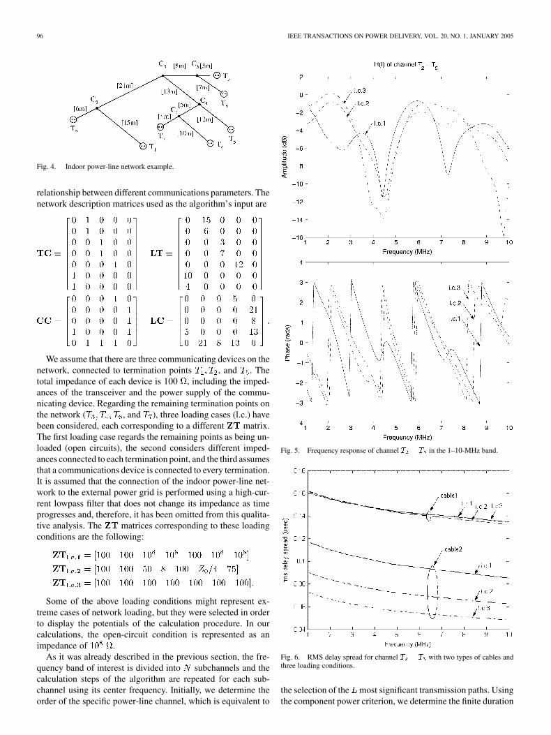
Fig. 4. Indoor power-line network example.
relationship between different communications parameters. Thenetwork description matrices used as the algorithm’s input are
We assume that there are three communicating devices on thenetwork, connected to termination points , and . Thetotal impedance of each device is 100 , including the imped-ances of the transceiver and the power supply of the commu-nicating device. Regarding the remaining termination points onthe network ( , and ), three loading cases (l.c.) havebeen considered, each corresponding to a different matrix.The first loading case regards the remaining points as being un-loaded (open circuits), the second considers different imped-ances connected to each termination point, and the third assumesthat a communications device is connected to every termination.It is assumed that the connection of the indoor power-line net-work to the external power grid is performed using a high-cur-rent lowpass filter that does not change its impedance as timeprogresses and, therefore, it has been omitted from this qualita-tive analysis. The matrices corresponding to these loadingconditions are the following:
Some of the above loading conditions might represent ex-treme cases of network loading, but they were selected in orderto display the potentials of the calculation procedure. In ourcalculations, the open-circuit condition is represented as animpedance of .
As it was already described in the previous section, the fre-quency band of interest is divided into subchannels and thecalculation steps of the algorithm are repeated for each sub-channel using its center frequency. Initially, we determine theorder of the specific power-line channel, which is equivalent to
Fig. 5. Frequency response of channel T � T in the 1–10-MHz band.
Fig. 6. RMS delay spread for channel T � T with two types of cables andthree loading conditions.
the selection of the most significant transmission paths. Usingthe component power criterion, we determine the finite duration

ANASTASIADOU AND ANTONAKOPOULOS: MULTIPATH CHARACTERIZATION OF INDOOR POWER-LINE NETWORKS 97
Fig. 7. Maximum deviation of power magnitude response of channels T � T and T � T with nonflat subchannels marked.
of the channel’s impulse response . This implies that the im-pulse response is assumed to decay fast enough, so that beyondthe th arriving component, the contribution to the overall re-ceived signal power becomes insignificant. The frequency re-sponse of the transmission channel from point to , calcu-lated for a power threshold of 96% and using all three loadingconditions is shown in Fig. 5. This figure demonstrates the ef-fect of varying loading conditions on the channel’s frequencyresponse. As the loading conditions change, the channel mayexperience deep fading conditions that make some subchannelsunsuitable for data transmission.
The channel’s rms delay spread as a function of frequency ispresented in Fig. 6 for two different types of cables described in[6] (cable1) and [9] (cable2). Cable1 is the type used for all otherresults demonstrated in this section. It can be concluded that therms delay spread strongly depends on the cable’s characteristics.Additionally, we observe that the effect of the varying loadingconditions also depends on the cable’s type.
The presented algorithm can also be used to determine the op-timum subchannel bandwidth that has to be selected sothat the channel response is considered constant within the cor-responding frequency range. In this respect, the channel appears
TABLE IOPTIMUM SUBCHANNEL BANDWIDTH
as frequency nonselective for any transmitted signal with band-width BW . Considering different levels of power mag-nitude deviation, the calculated optimum BW on thechannel for all three loading conditions is shown in Table I.
Moreover, given a certain BW and a predefined deviationthreshold in the channel response, we can estimate the numberof efficient subchannels regarding the flatness of their response.In Fig. 7, we present the maximum power magnitude deviationfor BW kHz and we mark the inefficient (nonflat) sub-channels, according to the 0.5-dB deviation threshold. The sub-figures on the left correspond to the channel, while the
98 IEEE TRANSACTIONS ON POWER DELIVERY, VOL. 20, NO. 1, JANUARY 2005
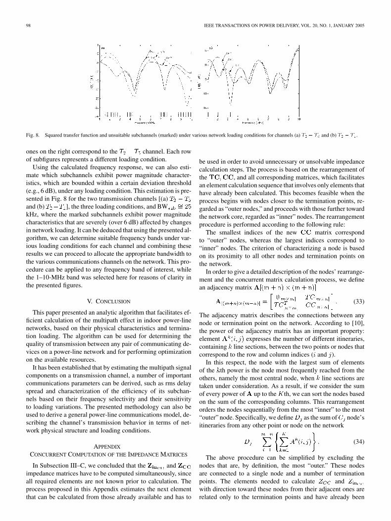
Fig. 8. Squared transfer function and unsuitable subchannels (marked) under various network loading conditions for channels (a) T � T and (b) T � T .
ones on the right correspond to the channel. Each rowof subfigures represents a different loading condition.
Using the calculated frequency response, we can also esti-mate which subchannels exhibit power magnitude character-istics, which are bounded within a certain deviation threshold(e.g., 6 dB), under any loading condition. This estimation is pre-sented in Fig. 8 for the two transmission channels [(a)and (b) ], the three loading conditions, and BWkHz, where the marked subchannels exhibit power magnitudecharacteristics that are severely (over 6 dB) affected by changesin network loading. It can be deduced that using the presented al-gorithm, we can determine suitable frequency bands under var-ious loading conditions for each channel and combining theseresults we can proceed to allocate the appropriate bandwidth tothe various communications channels on the network. This pro-cedure can be applied to any frequency band of interest, whilethe 1–10-MHz band was selected here for reasons of clarity inthe presented figures.
V. CONCLUSION
This paper presented an analytic algorithm that facilitates ef-ficient calculation of the multipath effect in indoor power-linenetworks, based on their physical characteristics and termina-tion loading. The algorithm can be used for determining thequality of transmission between any pair of communicating de-vices on a power-line network and for performing optimizationon the available resources.
It has been established that by estimating the multipath signalcomponents on a transmission channel, a number of importantcommunications parameters can be derived, such as rms delayspread and characterization of the efficiency of its subchan-nels based on their frequency selectivity and their sensitivityto loading variations. The presented methodology can also beused to derive a general power-line communications model, de-scribing the channel’s transmission behavior in terms of net-work physical structure and loading conditions.
APPENDIX
CONCURRENT COMPUTATION OF THE IMPEDANCE MATRICES
In Subsection III–C, we concluded that the andimpedance matrices have to be computed simultaneously, sinceall required elements are not known prior to calculation. Theprocess proposed in this Appendix estimates the next elementthat can be calculated from those already available and has to
be used in order to avoid unnecessary or unsolvable impedancecalculation steps. The process is based on the rearrangement ofthe , and all corresponding matrices, which facilitatesan element calculation sequence that involves only elements thathave already been calculated. This becomes feasible when theprocess begins with nodes closer to the termination points, re-garded as “outer nodes,” and proceeds with those further towardthe network core, regarded as “inner” nodes. The rearrangementprocedure is performed according to the following rule:
The smallest indices of the new matrix correspondto “outer” nodes, whereas the largest indices correspond to“inner” nodes. The criterion of characterizing a node is basedon its proximity to all other nodes and termination points onthe network.
In order to give a detailed description of the nodes’ rearrange-ment and the concurrent matrix calculation process, we definean adjacency matrix
(33)
The adjacency matrix describes the connections between anynode or termination point on the network. According to [10],the power of the adjacency matrix has an important property:element expresses the number of different itineraries,containing line sections, between the two points or nodes thatcorrespond to the row and column indices ( and ).
In this respect, the node with the largest sum of elementsof the th power is the node most frequently reached from theothers, namely the most central node, when line sections aretaken under consideration. As a result, if we consider the sumof every power of up to the th, we can sort the nodes basedon the sum of the corresponding columns. This rearrangementorders the nodes sequentially from the most “inner” to the most“outer” node. Specifically, we define as the sum of node’sitineraries from any other point or node on the network
(34)
The above procedure can be simplified by excluding thenodes that are, by definition, the most “outer.” These nodesare connected to a single node and a number of terminationpoints. The elements needed to calculate andwith direction toward these nodes from their adjacent ones arerelated only to the termination points and have already been

ANASTASIADOU AND ANTONAKOPOULOS: MULTIPATH CHARACTERIZATION OF INDOOR POWER-LINE NETWORKS 99
determined in previous steps. Therefore, we characterize thesenodes as the most “outer” ones and assign them the smallestindices (regardless of the order between them). The remainingnodes have to be assigned a new index according to the aboveprocedure.
The power , where the calculation procedure stops, is de-termined as the consecutive powers of are calculated. The
th power is the last to be derived, when there is at least oneitinerary between every pair of termination points, expressed asfollows:
(35)
This rearrangement of the nodes gives a new signifi-cant property, while its symmetry across the zero diagonal ismaintained. Keeping the naming convention that considers thecolumn node as the node of departure and the row node asthe destination, it can be concluded that elements above diag-onal indicate direction from “inner to outer” nodes,whereas elements beneath diagonal indicate directionfrom “outer to inner” nodes. It can easily be shown that ifis an “outer” node compared to is the equivalentimpedance resulting from the parallel connection of all inputimpedances appearing at node toward the “outer” direction,which means that elements above the diagonal require only el-ements located above it as well. Furthermore, it is valid to con-sider that each node can be connected to a number of more“outer” nodes (elements above the diagonal) but only to onemore “inner” node (element beneath the diagonal), meaning thatthere is only one nonzero element per column beneath the diag-onal. By symmetry, only one nonzero element per line is locatedabove the diagonal.
Therefore, and matrices can be computed using(25) and (26) in the most efficient manner:
1) The process begins with the calculation of each line of thematrices above the diagonal, beginning with the first line.Calculation of the single nonzero element of the th linerequires all of the elements of column of , whichhave already been calculated, and the elements of column
of , except the one on line . Since the directionis “from inner to outer” , all needed elements
have , because they are locatedabove the diagonal in column and have been calculatedin previous iterations.
2) The process continues with the calculation of eachcolumn of the matrices beneath the diagonal, beginningwith column and repeating until column .For the calculation of the only nonzero element in column
, the required elements lie in column. Since beneath the diagonal, refers to
columns whose elements have already been determined.
REFERENCES
[1] N. Pavlidou, A. J. H. Vinck, J. Yazdani, and B. Honary, “Power line com-munications: State of the art and future trends,” IEEE Commun. Mag.,vol. 41, pp. 34–40, Apr. 2003.
[2] D. Liu, B. Flint, B. Gaucher, and Y. Kwark, “Wide band AC powerline characterization,” IEEE Trans. Consumer Electron., vol. 45, pp.1087–1097, Nov. 1999.
[3] H. Philips, “Modeling of powerline communication channels,” in Proc.Int. Symp. Power-Line Commun., Lancaster, U.K., 1999, pp. 14–21.
[4] M. Zimmermann and K. Dostert, “A multipath model for the powerlinechannel,” IEEE Trans. Commun., vol. 50, pp. 553–559, Apr. 2002.
[5] , “Analysis and modeling of impulsive noise in broad-band power-line communications,” IEEE Trans. Electromagn. Compat., vol. 44, pp.249–258, Feb. 2002.
[6] S. Tsuzuki, T. Takamatsu, H. Nishio, and Y. Yamada, “An estimationmethod of the transfer function of indoor power-line channels forJapanese houses,” in Proc. Int. Symp. Power-Lines Commun., Athens,Greece, 2002, pp. 55–59.
[7] T. C. Banwell and S. Galli, “On the symmetry of the power line channel,”in Proc. Int. Symp. Power-Lines Commun., Malmo, Sweden, 2001, pp.325–330.
[8] A. Voglgsang, T. Langguth, G. Korner, H. Steckenbiller, and R. Knorr,“Measurement characterization and simulation of noise on power-linechannels,” in Proc. Int. Symp. Power-Lines Commun., Limerick, Ireland,2000, pp. 139–146.
[9] F. Issa and A. Abdouss, “Indoor PLC network simulator,” in Proc. Int.Symp. Power-Lines Commun., Athens, Greece, 2002, pp. 36–39.
[10] V. K. Balakrishnan, Schaum’s Outline of Theory and Problems of GraphTheory. New York: McGraw-Hill, 1997.
Despina Anastasiadou was born in Thessaloniki,Greece, in 1975. She received the Diploma and thePh.D. degrees in electrical engineering from theDepartment of Electrical and Computer Engineering,University of Patras, Patras, Greece, in 1998 and2004, respectively.
Since September 1998, she has been a ResearchEngineer with the Laboratory of Electromagnetics,participating in R&D projects supported by theGreek Government and European industries. In2000, she joined the Computer Technology Institute,
Patras. Her research interests include data communication networks with anemphasis on power-line communications, signal processing, and embeddedsystems design.
Ms. Anastasiadou is a member of the Technical Chamber of Greece.
Theodore Antonakopoulos (M’88–SM’99) wasborn in Patras, Greece, in 1962. He received theDiploma and Ph.D. degrees in electrical engineeringfrom the Department of Electrical Engineering,University of Patras, in 1985 and 1989, respectively.
Currently, he is an Associate Professor with theFaculty of the Electrical Engineering Department,University of Patras. In September 1985, he joinedthe Laboratory of Electromagnetics, University ofPatras, participating in various R&D projects for theGreek Government and the European Union, initially
as a Research Staff Member and, subsequently, as the Senior Researcher ofthe Communications Group. His research interests include data-communica-tion networks, local-area networks (LANs), and wireless networks, with anemphasis on performance analysis, efficient hardware implementation, andrapid prototyping. He has many publications in the above areas and activelyparticipates in several R&D projects of European industries.
Dr. Antonakopoulos is a member of the Technical Chamber of Greece.