Multi-scale mechanical improvement produced in carbon ...
11
Review Multi-scale mechanical improvement produced in carbon nanotube fibers by irradiation cross-linking T. Filleter a , H.D. Espinosa b, * a Department of Mechanical & Industrial Engineering, University of Toronto, 5 King’s College Rd., Toronto, ON, Canada M5S 3G8 b Department of Mechanical Engineering, Northwestern University, 2145 Sheridan Rd., Evanston, IL 60208, USA ARTICLE INFO Article history: Received 24 September 2012 Accepted 8 December 2012 Available online 19 December 2012 ABSTRACT Fibers and yarns based on carbon nanotubes (CNT) are emerging as a possible improve- ment over more traditional high strength carbon fibers used as reinforcement elements in composite materials. This is driven by a desire to translate the exceptional mechanical properties of individual CNT shells to achieve high performance macroscopic fibers and yarns. One of the central limitations in this approach is the weak shear interactions between adjacent CNT shells and tubes within macroscopic fibers and yarns. Furthermore, the multiple levels of interaction, e.g., between tubes within a multi-walled CNT or between bundles within a fiber, compound the problem. One promising direction to overcome this limitation is the introduction of strong and stiff cross-linking bonds between adjacent carbon shells. A great deal of research has been devoted to studying such cross-linking by the irradiation of CNT based materials using either high energy particles, such as elec- trons, to directly covalently cross-link CNTs, or electromagnetic irradiation, such as gamma rays to strengthen polymer cross-links between CNT shells and tubes. Here we review recent progress in the field of irradiation-induced cross-linking at multiple levels in CNT based fibers with a focus on mechanical property improvements. Ó 2012 Elsevier Ltd. All rights reserved. Contents 1. Experimental and theoretical demonstration of weak shear interactions between CNT tubes and shells ................. 2 1.1. Shells within MWCNTs ....................................................................... 2 1.2. CNTs within bundles ......................................................................... 2 2. Irradiation methods for cross-linking of graphite and CNTs ............................................... 4 2.1. High energy particle irradiation ................................................................ 4 2.1.1. Type and role of defects ................................................................ 4 2.1.2. Knock on energy requirements ........................................................... 4 2.2. Electromagnetic irradiation .................................................................... 4 3. Electron irradiation induced mechanical improvements at different length scales in CNT fibers ................... 5 3.1. Shells within MWCNTs ....................................................................... 5 3.2. CNTs within SWCNT bundles .................................................................. 6 0008-6223/$ - see front matter Ó 2012 Elsevier Ltd. All rights reserved. http://dx.doi.org/10.1016/j.carbon.2012.12.016 * Corresponding author. E-mail address: [email protected] (H.D. Espinosa). CARBON 56 (2013) 1 – 11 Available at www.sciencedirect.com journal homepage: www.elsevier.com/locate/carbon
-
Upload
khangminh22 -
Category
Documents
-
view
4 -
download
0
Transcript of Multi-scale mechanical improvement produced in carbon ...
C A R B O N 5 6 ( 2 0 1 3 ) 1 – 1 1
.sc ienced i rec t .com
Avai lab le a t wwwjournal homepage: www.elsevier .com/ locate /carbon
Review
Multi-scale mechanical improvement produced in carbonnanotube fibers by irradiation cross-linking
T. Filleter a, H.D. Espinosa b,*
a Department of Mechanical & Industrial Engineering, University of Toronto, 5 King’s College Rd., Toronto, ON, Canada M5S 3G8b Department of Mechanical Engineering, Northwestern University, 2145 Sheridan Rd., Evanston, IL 60208, USA
A R T I C L E I N F O
Article history:
Received 24 September 2012
Accepted 8 December 2012
Available online 19 December 2012
0008-6223/$ - see front matter � 2012 Elsevihttp://dx.doi.org/10.1016/j.carbon.2012.12.016
* Corresponding author.E-mail address: [email protected]
A B S T R A C T
Fibers and yarns based on carbon nanotubes (CNT) are emerging as a possible improve-
ment over more traditional high strength carbon fibers used as reinforcement elements
in composite materials. This is driven by a desire to translate the exceptional mechanical
properties of individual CNT shells to achieve high performance macroscopic fibers and
yarns. One of the central limitations in this approach is the weak shear interactions
between adjacent CNT shells and tubes within macroscopic fibers and yarns. Furthermore,
the multiple levels of interaction, e.g., between tubes within a multi-walled CNTor between
bundles within a fiber, compound the problem. One promising direction to overcome this
limitation is the introduction of strong and stiff cross-linking bonds between adjacent
carbon shells. A great deal of research has been devoted to studying such cross-linking
by the irradiation of CNT based materials using either high energy particles, such as elec-
trons, to directly covalently cross-link CNTs, or electromagnetic irradiation, such as gamma
rays to strengthen polymer cross-links between CNT shells and tubes. Here we review
recent progress in the field of irradiation-induced cross-linking at multiple levels in CNT
based fibers with a focus on mechanical property improvements.
� 2012 Elsevier Ltd. All rights reserved.
Contents
1. Experimental and theoretical demonstration of weak shear interactions between CNT tubes and shells . . . . . . . . . . . . . . . . . 2
1.1. Shells within MWCNTs . . . . . . . . . . . . . . . . . . . . . . . . . . . . . . . . . . . . . . . . . . . . . . . . . . . . . . . . . . . . . . . . . . . . . . . 2
1.2. CNTs within bundles. . . . . . . . . . . . . . . . . . . . . . . . . . . . . . . . . . . . . . . . . . . . . . . . . . . . . . . . . . . . . . . . . . . . . . . . . 2
2. Irradiation methods for cross-linking of graphite and CNTs . . . . . . . . . . . . . . . . . . . . . . . . . . . . . . . . . . . . . . . . . . . . . . . 4
2.1. High energy particle irradiation . . . . . . . . . . . . . . . . . . . . . . . . . . . . . . . . . . . . . . . . . . . . . . . . . . . . . . . . . . . . . . . . 4
2.1.1. Type and role of defects . . . . . . . . . . . . . . . . . . . . . . . . . . . . . . . . . . . . . . . . . . . . . . . . . . . . . . . . . . . . . . . . 4
2.1.2. Knock on energy requirements. . . . . . . . . . . . . . . . . . . . . . . . . . . . . . . . . . . . . . . . . . . . . . . . . . . . . . . . . . . 4
2.2. Electromagnetic irradiation . . . . . . . . . . . . . . . . . . . . . . . . . . . . . . . . . . . . . . . . . . . . . . . . . . . . . . . . . . . . . . . . . . . . 4
3. Electron irradiation induced mechanical improvements at different length scales in CNT fibers . . . . . . . . . . . . . . . . . . . 5
3.1. Shells within MWCNTs . . . . . . . . . . . . . . . . . . . . . . . . . . . . . . . . . . . . . . . . . . . . . . . . . . . . . . . . . . . . . . . . . . . . . . . 5
3.2. CNTs within SWCNT bundles . . . . . . . . . . . . . . . . . . . . . . . . . . . . . . . . . . . . . . . . . . . . . . . . . . . . . . . . . . . . . . . . . . 6
er Ltd. All rights reserved.du (H.D. Espinosa).
2 C A R B O N 5 6 ( 2 0 1 3 ) 1 – 1 1
3.3. Cross-linking of shells and tubes within DWCNT bundles and CNT yarns . . . . . . . . . . . . . . . . . . . . . . . . . . . . . . . 7
3.4. Comparison of electron beam energies and defect densities . . . . . . . . . . . . . . . . . . . . . . . . . . . . . . . . . . . . . . . . . . 7
4. Application of irradiation cross-linking to macroscopic CNT yarns . . . . . . . . . . . . . . . . . . . . . . . . . . . . . . . . . . . . . . . . . . 8
4.1. Key challenges: current density and electron penetration depth . . . . . . . . . . . . . . . . . . . . . . . . . . . . . . . . . . . . . . . 8
4.2. Manufacturing approaches: continuous spinning fabrication . . . . . . . . . . . . . . . . . . . . . . . . . . . . . . . . . . . . . . . . . 9
5. Summary . . . . . . . . . . . . . . . . . . . . . . . . . . . . . . . . . . . . . . . . . . . . . . . . . . . . . . . . . . . . . . . . . . . . . . . . . . . . . . . . . . . . . . . 9
Acknowledgments . . . . . . . . . . . . . . . . . . . . . . . . . . . . . . . . . . . . . . . . . . . . . . . . . . . . . . . . . . . . . . . . . . . . . . . . . . . . . . . . 9
References . . . . . . . . . . . . . . . . . . . . . . . . . . . . . . . . . . . . . . . . . . . . . . . . . . . . . . . . . . . . . . . . . . . . . . . . . . . . . . . . . . . . . . 9
1. Experimental and theoretical demonstrationof weak shear interactions between CNTtubes and shells
sensor in situ a TEM, estimated that the interlayer shear
was dominated by van der Walls interactions with a corre-
sponding interlayer shear strength of <0.05 MPa and an inter-
Despite the great potential of applying CNTs in composite
materials [1–8], an intrinsic limitation in directly scaling up
the exceptional mechanical properties of CNTs [9,10] to mac-
roscopic fibers and yarns exists in the form of weak interfacial
shear properties between adjacent CNT shells. The same un-
ique nature of in plane sp2 bonding in CNTs, which achieves
high mechanical strength and stiffness, also leads to weak
out of plane bonding. This is exemplified in graphite which
exhibits some of the best solid lubricating properties found
in nature due to inter-planar shear. Such weak inter-plane
bonding is evident from theoretical predictions of interfacial
properties (cohesion energy, interfacial shear strength, etc.)
of stacked graphitic sheets and tubes. The cohesion energy
(or interlayer binding energy) in graphite has been calculated
by assuming a Lennard–Jones like potential to be 0.33 J/m2
[11]. A variety of experimental studies have demonstrated
interlayer cohesion energies for sp2 bonded carbon based
materials consistent with this theoretical prediction includ-
ing; multiwalled carbon nanotube (MWCNT) shells (0.198–
0.21 J/m2) [12,13], CNT bundles (0.1–0.6 J/m2) [25], and graphite
(0.26–0.37 J/m2) [11,14]. Similarly the interfacial shear strength
(IFSS) of bare CNT shell–shell interfaces has been experimen-
tally estimated to be as low as 0.05–0.3 MPa [9,12,15]. To put
these interfacial properties in perspective the IFSS within typ-
ical high performance fiber reinforced composites, such as
aramid/epoxy and carbon fiber/epoxy composites, is two to
three orders of magnitude higher, on the order of tens of
MPa [16].
1.1. Shells within MWCNTs
The weak interfacial shear properties that exist between
shells within individual CNTs was experimentally elucidated
through in situ transmission electron microscopy (TEM) and
scanning electron microscopy (SEM) shear experiments.
Cumings and Zettl [17] conducted one of the first direct dem-
onstrations of the sword-in-sheath failure and weak interfa-
cial shear between the inner shells of a MWCNT. In this
study the inner shells of a MWCNTwere pulled out of the out-
er shell in a reversible process in situ TEM (Fig. 1c). They esti-
mated the van der Walls (vdW) interlayer force to be
approximately 2.3 · 10�14 N/atom. They also demonstrated
that the pulled out inner shells tend to be pulled back in,
due to the vdW interactions between the inner and outer
shells, with nearly zero energy dissipation. Subsequent pull-
out studies by Kis et al. [12], which utilized an AFM force
layer cohesion energy of 33 meV/atom [12], in good agreement
with estimates determined from an energy analysis of bare
collapsed MWCNTs [13].
The shear interactions between shells of a MWCNT was
also quantified by Yu et al. [15] using a similar AFM cantilever
based method in situ a SEM. In these experiments, the outer
shell of a MWCNT was first pulled in tension, leading to the
outer shell rupture followed by the controlled pull out of the
inner MWCNT shells. The pull out force measured by Yu
et al. was described as being composed of two components:
(1) the shear interaction between shells, and (2) the capillary
effect and edge interactions by dangling bonds at the end of
the MWCNTs. In their study the static shear strength was
estimated to be 0.08–0.3 MPa (corresponding to an experimen-
tal force of 85–219 nN), and the combined capillary and edge
effect was measured to contribute 80–150 nN, dominating
the experimentally observed forces.
The low force required for sliding between adjacent
MWCNT shells was further investigated by Espinosa and co-
workers using a MEMS platform in situ a TEM [9,21]
(Fig. 1d). They measured an even lower average post failure
force of 35 nN required to pullout the 11 inner shells of a
14 nm diameter MWCNTwith respect to the outer shell. More-
over, using DFT, TB-DFT, and reactive force fields they investi-
gated computationally the interaction between tube shells
[9,21].
1.2. CNTs within bundles
Similarly weak interfacial interactions have also been pre-
dicted and measured experimentally at the next structural le-
vel of hierarchy in CNT fibers; CNT bundles. In-situ SEM
tensile experiments conducted on individual single- (SWCNT)
and double-walled (DWCNT) carbon nanotube bundles have
revealed a similar sword-in-sheath failure mechanism in
which inner CNTs within bundles pull out with respect to
an outer shell of CNTs [6,22,23].
Yu et al. [23] conducted tensile tests on SWCNT bundles
in situ SEM using an AFM cantilever based method. Their ten-
sile test data was best fitted by a model, which assumed that
only the outer perimeter of SWCNTs in the bundle carried the
load, consistent with a sword-in-sheath failure. Although
they did not measure the force required to pullout inner
SWCNTs from the bundles, the SEM images of the bundles
after tensile failure also suggested this mode of failure. More
recently a novel method of in situ SEM peeling between two
SWCNT bundles was used to measure an adhesion energy

Fig. 1 – Shear interfaces at multiple length scales within CNT based fibers. (a) DWCNT bundle-bundle interfaces. Adapted
from [18]. (b) SWCNT-SWCNT interface within a SWCNT bundle. Adapted from [19]. (c) and (d) MWCNT shell-shell interfaces.
Adapted from [17] [9]. (e) Schematic of the different CNT yarn length scales. Adapted from [8].
C A R B O N 5 6 ( 2 0 1 3 ) 1 – 1 1 3
of 0.12–0.16 nJ/m [19] (Fig. 1b); however, the width of the con-
tact between the two bundles was not reported, therefore the
cohesion energy per unit area is unknown, making compari-
son with other studies difficult.
The force required to slide adjacent DWCNTs within bun-
dles was measured recently by Filleter et al. [22]. In this study
a normalized pullout force of 1.7 ± 1.0 nN/CNT-CNT interac-
tion was measured for sliding of a smaller inner bundle of
DWCNTs out of a larger outer shell of DWCNTs. This force
translates to a lower limit estimate of the average interfacial
shear strength of approximately 7.8 MPa. This estimation
considers as the interfacial area the continuous cylindrical
surface area of the small inner bundle of DWCNTs that is
pulled out in the experiment (A = p*l*d, where l is the DWCNT
overlap length and d is the inner bundle diameter). The true
shear strength of the interface is expected to be significantly
higher as the interfacial area is not continuous, but instead
composed of discrete CNT-CNT interfaces, and the interfacial
shear stress in the axial direction is not uniform [24]. Through
comparison with molecular mechanics (MM) and density
functional theory (DFT) simulations of sliding between adja-
cent CNTs in bundles it was identified that factors contribut-
ing to the pullout force (in units of nN/CNT-CNT interaction)
included the creation of new CNT surfaces (<0.4), carbonyl
functional groups terminating the free ends (<0.16), corruga-
tion of the CNT-CNT interaction (�0.1), and polygonilization
of the CNTs in the bundle (�0.02–0.08). In addition a top down
analysis of the experimental results revealed that greater
than one half of the pullout force was due to dissipative
forces. This finding of behavior at the CNT bundle level signif-
icantly differs from the behavior of pullout in individual
MWCNTs for which dissipation is found to be negligible [17].
These findings suggest that the bundle hierarchical level
may play an important role in energy dissipation and tough-
ness of CNT fibers and yarns. This is also consistent with
the greater shear strength measured for bundle pullout
(�7.8 MPa) as compared to MWCNT shell pullout (�0.05–
0.3 MPa).
Yang et al. [25] experimentally investigated the friction
within macroscopic SWCNT fibers by loading large fibers in
tension. In contrast to the previously discussed studies here
the fibers were of very large diameter (10’s lm) and long
lengths (�3 mm). It should be noted that the authors of Ref.
[25] used the term ‘‘bundles’’ to describe the material under
study, however, that term is more typically used to refer to
close-packed, aligned CNT structures with diameters on the
order of 10’s of nm (Fig. 1). During the tensile loading, they
monitored both the elastic behavior and the inelastic behav-
ior of the yarns due to SWCNTs sliding on each other. They
estimated the cohesive energy per unit area of the SWCNTs
to be in the range of 0.1–0.6 J/m2, by normalizing the friction
energy (dissipated during the plastic deformation) by the
change in the contact area between the bundles. While this
method can be used to obtain an average value for the
4 C A R B O N 5 6 ( 2 0 1 3 ) 1 – 1 1
cohesive energy between SWCNTs, it suffers from uncertain-
ties in the estimation of the edge effect and the true contact
area between SWCNTs. In addition the analysis assumes
close packing of SWCNTs in the large diameter fibers, which
leads to further uncertainties.
2. Irradiation methods for cross-linking ofgraphite and CNTs
2.1. High energy particle irradiation
One approach which can increase the shear strength of the
weak CNT interfaces described in the previous section is to
introduce interlayer covalent bonding between carbon atoms
of adjacent graphitic layers through particle irradiation [9,26–
30]. The effect of radiation on graphite has been a topic of
interest for many years [31–33]. For example, in 1963 Goggin
demonstrated that the Young’s modulus of graphite could
be increased by electron irradiation and thermal annealing
[33]. Radiation of carbon nanostructures, such as CNTs, have
only more recently been investigated due to the potential
beneficial effects. Such an approach requires locally modify-
ing the in-plane sp2 bonding to sp3 type bonding at specific
sites within the CNT material. The benefit to the interfacial
shear strength can be understood by considering the relative
single bond energies of the sp3 C–C bonds found in diamond
(�0.88 eV/atom) [34] as compared to the interplanar binding
energy of graphite sheets (�0.02 eV/atom) [35]. Recently, irra-
diation with high energy particles, including electrons, pro-
tons, and ions, has been both theoretically and
experimentally demonstrated as an effective method to intro-
duce interlayer covalent bonding in graphite and CNT materi-
als by the formation of cross-linking defects in the graphitic
structures [9,21,27,28,36–38]. High energy electrons, in partic-
ular, have been studied extensively with application to
mechanical property improvements achieved through cross-
linking CNT shells and tubes [9,21,27,30,31,37]. For a general
review of the effects of irradiation on other nanostructures,
the reader is referred to the following review articles [39,40].
2.1.1. Type and role of defectsIrradiation of CNTs and graphite layers with high energy elec-
trons leads to the formation of atomic-scale defects due to
the transfer of energy from the incident electron to the car-
bon atoms in the graphitic structures. The creation of a defect
requires that the target atom acquires sufficient kinetic en-
ergy to be displaced from its original position in the lattice.
The energy thresholds for electron irradiation induced defect
creation in graphite and CNT will be discussed further in
Section 2.1.2.
Defects formed by electron irradiation in graphite and
CNTs can be in the form of point defects [21,41] (Fig. 2a) or lar-
ger dimension defects such as dislocations and voids in gra-
phitic layers [42] (Fig. 2b). For applications aimed at
improving the mechanical behavior of CNT materials, point
defects that bridge adjacent layers are most desirable as lar-
ger in plane defects can significantly reduce the intrinsic
mechanical properties of the CNT shells. MM simulations
conducted by Mielke et al. [43] have demonstrated that CNT
strength, in particular, is very sensitive to clustering of vacan-
cies (holes), which can lead to strength reductions of as much
as 60% as compared to pristine tubes. In contrast, Sam-
malkorpi et al. [44] and Haskins et al. [45] have shown,
through molecular dynamics (MD) simulations, that the ten-
sile Young’s Modulus of CNTs is much less sensitive to de-
fects. Furthermore a small density of interlayer point
defects, can significantly improve load transfer between adja-
cent CNT shells and tubes [21,37].
Irradiation induced point defects bridging graphitic layers
can take several forms including; di-vacancy, interstitial, and
Frenkel pair defects [41]. Telling et al. [41] demonstrated
through first-principle quantum mechanics calculations, that
in addition to interstitials atoms, effectively cross-linking
adjacent graphitic layers, vacancies formed as a result of irra-
diation can also re-configure to covalently cross-link layers
despite the relatively large atomic spacing of adjacent layers.
2.1.2. Knock on energy requirementsThere are minimum energy requirements of the incident irra-
diation particle to knock out a carbon atom from the CNT lat-
tice. A detailed discussion of these requirements can be found
in a previous review article on irradiation of nanostructures
[39]. Here we will briefly summarize the key points as related
to irradiation of CNTs. The knock on threshold energy of an
incoming particle is related to the displacement threshold en-
ergy (Td) and the masses of the incoming particle (mi) and a
carbon atom (mc) as follows [39]:
Eth ¼ðmi þmcÞ2
4mcmiTd ð1Þ
In the case of electron irradiation, due to the large relative
mass of the carbon atom (mc) as compared to the electron
(me), the expression can be simplified to: Eth � mc4me
Td suggesting
that electrons with high kinetic energy are required to satisfy
the threshold energy. This corresponds to threshold electron
energies on the order of �100 keV required to displace carbon
atoms in the CNT lattice. More specifically the threshold energy
is dependent on a number of factors including CNT diameter,
chirality, angle of incidence between incoming electron and
CNT lattice. Theoretical studies have predicted displacement
threshold energies of �15–22 eV [46–49] for incident electrons
perpendicular to the CNT tube surface and as high as �33–
44 eV [47] for tangential incident electrons. Furthermore, small
diameter CNTs are predicted to require lower displacement
threshold than larger tubes [49]. These predicted displacement
thresholds translate to required threshold electron energies of
ranging from �82 keV for small CNTs with electrons in a per-
pendicular configuration to as high as�240 keV for large CNTs
in a tangential configuration.
2.2. Electromagnetic irradiation
Another approach to enhancing shear interactions between
adjacent CNTs within CNT fibers is by electromagnetic irradi-
ation of polymer/CNT interfaces to bond polymer chains
between adjacent CNTs. Unlike high energy particle irradia-
tion, which creates covalent bonds directly between adjacent
CNTs, electromagnetic irradiation can lead to either covalent
bonding between polymer chains which bridge adjacent CNTs
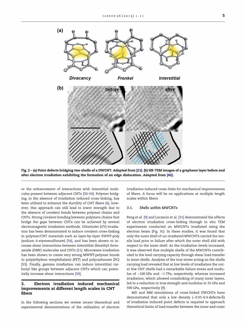
Fig. 2 – (a) Point defects bridging two shells of a DWCNT. Adapted from [21]. (b) HR-TEM images of a graphene layer before and
after electron irradiation exhibiting the formation of an edge dislocation. Adapted from [42].
C A R B O N 5 6 ( 2 0 1 3 ) 1 – 1 1 5
or the enhancement of interactions with interstitial mole-
cules present between adjacent CNTs [50–54]. Polymer bridg-
ing, in the absence of irradiation induced cross-linking, has
been utilized to enhance the ductility of CNT fibers [6], how-
ever, this approach can still lead to lower strength due to
the absence of covalent bonds between polymer chains and
CNTs. Strong covalent bonding between polymers chains that
bridge the gaps between CNTs can be achieved by several
electromagnetic irradiation methods. Ultraviolet (UV) irradia-
tion has been demonstrated to induce covalent cross-linking
in polymer/CNT materials such as layer-by-layer SWNT-poly
(sodium 4-styenesulfonate) [54], and has been shown to in-
crease shear interactions between interstitial dimethyl-form-
amide (DMF) molecules and CNTs [51]. Microwave irradiation
has been shown to create very strong MWNT-polymer bonds
to poly(ethylene terephthalate) (PET) and polycarbonate (PC)
[53]. Finally, gamma irradiation can induce interstitial car-
boxyl like groups between adjacent CNTs which can poten-
tially increase shear interactions [50].
3. Electron irradiation induced mechanicalimprovements at different length scales in CNTfibers
In the following sections we review recent theoretical and
experimental demonstrations of the utilization of electron
irradiation induced cross-links for mechanical improvements
of fibers. A focus will be on applications at multiple length
scales within fibers.
3.1. Shells within MWCNTs
Peng et al. [9] and Locascio et al. [21] demonstrated the effects
of electron irradiation cross-linking through in situ TEM
experiments conducted on MWCNTs irradiated using the
electron beam (Fig. 3c). In these studies, it was found that
only the outer shell of un-irradiated MWCNTs carried the ten-
sile load prior to failure after which the outer shell slid with
respect to the inner shell. As the irradiation levels increased,
it was observed that multiple shells of the MWCNTs contrib-
uted to the load carrying capacity through shear load transfer
to inner shells. Analysis of the true stress acting on the shells
carrying load revealed that at low levels of irradiation the out-
er few CNT shells had a remarkable failure stress and modu-
lus of �100 GPa and �1 TPa, respectively, whereas increased
irradiation, which allowed corsslinking of many inner layers,
led to a reduction in true strength and modulus to 35 GPa and
590 GPa, respectively [9].
MD and MM simulations of cross-linked DWCNTs have
demonstrated that only a low density (�0.01–0.4 defects/A)
of irradiation induced point defects is required to approach
theoretical limits of load transfer between the inner and outer

Fig. 3 – Atomistic simulations and experiments on electron induced crosslining in CNT materials. (a) Molecular mechanics
simulations of cross-linking a DWCNT. Adapted from [21]. (b) Molecular dynamics simulations of cross-linking a SWCNT
bundle. Adapted from [37]. (c) In-situ TEM experiments of cross-linking MWCNTs. Adapted from [9]. (d) AFM bending
experiments on SWCNT bundles. Adapted from [29].
6 C A R B O N 5 6 ( 2 0 1 3 ) 1 – 1 1
shells and increase the interlayer shear strength by orders of
magnitude [21,55] (Fig. 3a). Both Huhtala et al. [55] and Loca-
scio et al. [21] found that di-vacancy defects were more effec-
tive at increasing load transfer and interlayer shear strength
as compared to interstitial defects, whereas Locascio et al.
[21] also found that Frenkel defects were even more effective
than the other two point defect types. Considering the exper-
imental and theoretical findings of irradiation of MWCNTs
suggest that control of defect density and distribution within
the MWCNTs imparted by electron irradiation is a critical step
in optimizing their mechanical behavior. Only a low density
of cross-linking defects is required between each layer; how-
ever, achieving cross-link penetration, through many shells of
a MWCNT, may lead to a high defect density on the outer
shells and reduce their intrinsic strength and stiffness.
3.2. CNTs within SWCNT bundles
The next structural level in the hierarchy of CNT fibers is the
interaction between adjacent CNTs within close packed bun-
dles. At this level Kis et al. investigated the effects of electron
irradiation induced cross-linking defects on enhancing the
mechanical properties of SWCNT bundles by applying an
AFM based deflection method [27,29] (Fig. 3d). In their study
it was demonstrated that low doses (�5 · 1020 e/cm2) of elec-
tron irradiation at energies of 80 keV yielded a substantial in-
crease in the effective bending modulus up to �750 GPa [29].
Higher irradiation doses were found to significantly reduced
the modulus, in this case to as low as �100 GPa (at doses in
excess of 40 · 1020 e/cm2) due to the introduction of a high
density of defects in the SWCNT shells and a transition to
amorphous carbon structures. In addition, irradiation of elec-
trons with higher beam energies (200 keV) was not found to
lead to significant improvements in the bending stiffness.
This is likely attributed to both the resolution in the control
of the electron dose applied experimentally and the low resis-
tance to high energy beam damage for SWCNT (as compared
to MWCNTs) [39]. One limitation of the AFM bending based
method is that it does not allow for a determination of the
strength of the irradiated SWCNT bundles.
In the absence of experimental measurements, MD simu-
lations of SWCNT bundles have provided insights into the
achievable strength of irradiated bundles. Cornwell and
Welch [37] conducted MD simulations of SWCNT bundles
with a varying density of interstitial carbon atoms used to
emulate interstitial defects created by electron irradiation
(Fig. 3b). Here it was demonstrated that the strength of dis-
continues SWCNT bundles increased with cross-link density,
with a strength of up to 62 GPa at the optimal cross-link den-
sity of �0.7 nm�3. The authors reported that this configura-
tion consisted of 80.4 cross-links per CNT in the bundle
which had a length of 8000 A [37]. This corresponds to an
interfacial linear cross-link density between each SWCNT of
�0.01 cross-links/A. It is interesting to note that this optimal
C A R B O N 5 6 ( 2 0 1 3 ) 1 – 1 1 7
cross-link density, between tubes in a bundle, is in a similar
range to that found for the optimal cross-linking defect den-
sity, between shells in a MWCNT, as discussed in the previous
section [21,55].
In addition to the cross-link density, the length of individ-
ual CNTs within a CNT fiber can also influence the strength of
the fiber. MD simulations by Cornwell and Welch [37] pre-
dicted a high strength of �50 GPa for cross-linked bundles
with 8000 A long CNTs with a cross-link density of only
0.1 nm�3, whereas cross-linked bundles composed of 4000 A
long CNTs (with the same cross-sectional geometry) required
a crosslink density of 0.7 nm�3 to achieve a similar strength.
The implication of this finding is that CNT fibers composed
of longer CNTs would require lower irradiation treatments
(and hence a lower number of defects introduced) to achieve
the same improvements in strength.
3.3. Cross-linking of shells and tubes within DWCNTbundles and CNT yarns
In the last two sections, cross-linking of shells within
MWCNTs and cross-linking SWCNTs in bundles was dis-
cussed. Here we discuss a slightly more complex hierarchical
CNT structure, double-walled carbon nanotube (DWCNT)
bundles. This type of structure has two available levels of
interfaces that can be cross-linked by electron irradiation;
(1) the inner and outer shells within each DWCNT and (2)
the adjacent DWCNTs within the bundle.
Filleter et al. [30] have conducted experimental studies on
DCWNT bundles exposed to high energy electron irradiation
in a TEM (Fig. 4). As mentioned above this material has two
levels of hierarchy; inter tube shell-shell interactions as well
as inter bundle tube-tube interactions, which can be cross-
linked by irradiation. In this study it was found that both
the effective strength and elastic modulus of the DWCNT
bundles was increased by irradiation up to 17 GPa and
693 GPa respectively. The effective mechanical properties
were determined by considering a crossectional area, which
included the crossection of all tubes and shells with the
DWCNT bundles where the typical CNT shell thickness of
0.33 nm was assumed. The number of tubes within each bun-
dle was determined using a geometrical close packing model
and HRTEM images of the fringe patterns of each individual
bundle. The failure modes, identified from in situ TEM imag-
ing, of the bundles were found to depend on the irradiation le-
vel. In the case of minimally irradiated bundles (0.5 · 1020 e/
cm2) the outer tubes within the bundles failed during the ten-
sile test and slid with respect to the inner bundle of DWCNTs,
akin to the sword-in-sheath failure observed for MWCNT
shells. On the other hand, at optimal irradiation doses (�9–
11 · 1020 e/cm2) the bundles were found to fail across the en-
tire cross section of shells and tubes confirming effective load
transfer to the bundle interior.
In principle, the same mechanisms discussed above for
cross-linking adjacent CNTs within bundles can be applied
to cross-link the outer CNTs of adjacent CNT bundles. To date
this has not been demonstrated directly as both experiments
and simulations of the mechanical interactions between two
isolated CNT bundles, for example, are difficult and time
consuming. Initial demonstrations of the shear properties
between isolated CNT bundles have been achieved for poly-
mer cross-linked CNTs through in situ SEM and coarse-grain
modeling methods [18]. A future direction in such studies will
be to apply the same techniques to bundle-bundle junctions
exposed to electron irradiation.
3.4. Comparison of electron beam energies and defectdensities
As discussed in Section 3.2 the incident electron beam energy
is an important criterion for inducing and controlling cross-
linking defects in CNT fibers. The beam energy must be above
a threshold of approximately 80 keV in order to create defects
between shells and tubes [39]. Studies of MWCNTs have
demonstrated that higher beam energies in the range of
100–200 keV can also be very effective at crosslining MWCNTs
without significant degradation in the mechanical properties
of the CNT shells themselves [9,30]. This, however, is not the
case for SWCNTs that are less stable and can be rapidly
degraded under higher energy electron beams [29,39]. Even
higher electron beam energies of 1.25 MeV accompanied by
heating has also been shown to bond multiple SWCNTs into
continuous junctions [56], however it remains to be studied
as to whether these modifications introduce significant de-
fects and voids which can degrade the mechanical properties
of the individual CNT shells.
A very important consideration in utilizing electron irradi-
ation for enhancing the mechanical properties of CNTyarns is
the optimization of the benefits of cross-linking to transfer
load, and the detrimental effects of defect introduction into
CNT shells. This tradeoff has been experimentally demon-
strated in the context of both SWCNT and DWCNT bundles
[29,30]. In these studies the optimal electron dose was found
to be in a similar range of (�5–10 · 1020 e/cm2). Furthermore,
Kis et al. [29] demonstrated that at high levels of irradiation,
the structure of SWCNT bundles is transformed into an amor-
phous carbon structure. This was supported by both TEM
images of the resulting structures as well as bending moduli
that approach that expected for amorphous carbon [29]. Ra-
man spectroscopy investigations of CNTs irradiated with
electrons have also demonstrated a transition to amorphous
structures for high irradiation dose [57].
A key challenge that remains in connecting experimental
demonstrations of cross-linking improvements in CNTs with
theoretical predictions is a comparison of cross-linking defect
densities. Experimentally, it is very difficult to measure or
estimate the actual defect density imposed by electron beam
irradiation. Most studies simply report on the variation in
mechanical properties with the electron dose (typically in
e�/cm2). While this specifies the flux of electrons passing
though the material, the density of cross-linking defects
formed by the electron beam depends on a number of other
factors which include the electron energy, the curvature of
the CNT shells, the thickness of the CNT material, and the
mean free path of electron in the graphitic material. Although
this may be difficult to determine experimentally, direct com-
parison between experiments and atomistic simulations can
be used in the future to achieve insights into the experimen-
tal defect densities and help guide optimization of mechani-
cal properties. This will require modeling CNT systems that

Fig. 4 – Electron irradiation strengthening of double-walled carbon nanotube bundles. (Top) In-situ TEM images of DWCNT
bundles tested using a MEMS based tensile testing technique. (Bottom) Effective strength and tensile modulus as a function
of irradiation dose for different DWCNTs. Adapted from [30].
8 C A R B O N 5 6 ( 2 0 1 3 ) 1 – 1 1
match those found in experiments. This requirement is in
principle already achievable as MD simulations have already
been demonstrated for SWCNT bundles (dbundle = �5 nm,
dcnt = �0.7 nm Ncnt = 19, l = �800 nm [37]), which approach
sizes that have been tested experimentally (dbundle = �10 nm,
dcnt = �2.5 nm, Ncnt = 14, l = �2600 nm [30]).
4. Application of irradiation cross-linking tomacroscopic CNT yarns
Macroscopic CNT based yarns and fibers have been realized
using a number of different synthesis techniques, most nota-
bly, direct spinning in situ [20,58] and post spinning of CVD
grown mats [6] and spinning continuously draw CNT mats
from forests [3]. While these methods produce CNT fibers
with good mechanical properties, such as typical strengths
of �1 GPa, they do not take advantage of CNT cross-linking.
Several studies have applied irradiation techniques to cross-
link macroscopic CNTyarns and buckypapers [50,51,59]. Miao
et al. [50] used gamma irradiation to introduce increased lat-
eral interactions between CNTs within yarns spun from CNT
forests. Improvements in strength and stiffness of the yarns
were observed with irradiation, however no clear trend with
increasing irradiation level was observed (Fig. 5). The
improvements were attributed to the formation of carboxyl
like groups between adjacent CNTs due to gamma-irradiation
induced oxidation of the CNTs not by direct CNT-CNT cross-
linking. Ultraviolet (UV) light irradiation has also been applied
to cross-link CNT yarns by Miko et al. [51]. In this study in-
creases in both the elastic modulus and electrical conductiv-
ity were observed following UV irradiation. Here, similar to
the case of gamma-irradiation, the cross-linking was not in
the form of direct CNT covalent cross-linking of carbon
atoms, but instead by a UV initiated side reaction between
surface functional groups on the CNTs and DMF molecules
present from the original CNT suspension.
4.1. Key challenges: current density and electronpenetration depth
The application of electron irradiation for directly cross-link-
ing adjacent CNTs within macroscopic CNT yarns and fibers
remains to be studied. The two key challenges in achieving
successful macroscopic cross-linking are; (1) applying a high
enough current density over a large area in order to approach
the irradiation doses used in smaller scale studies, and (2)
addressing the issue of limited electron penetration depth
in order to achieve uniform irradiation over the entire cros-
sectional area of macroscopic fibers. As discussed in Section 3
the irradiation doses found to be optimal for cross-linking
CNTs and CNT bundles lie in the range of �5–10 · 1020 e/
cm2. In the TEM setup used for these experiments, the current
density was varied in the range of 0.3–2 A/cm2 [29,30], which
allowed the optimal doses to be delivered in a matter of sec-
onds or minutes. In contrast, industrial scale electron irradia-
tion equipment which is capable of delivering electron beams
which spread over large areas of mm or inches, typically oper-
ate on the order of �lA/cm2. Under such conditions it would
require days or months to irradiate a single CNT yarn sample
to a comparable dose, as the dose rate would be orders of
magnitude lower. Even for low Z elements (such as carbon)
the penetration depth of 200 keV electrons is <1 lm. Therefore
the electron beam will not be able to penetrate the entire
crossection of macroscopic CNT fibers which typically have
a diameter of 10–100 lm.
Fig. 5 – Gamma-irradiation of CNT yarns. (left) SEM image of a CNT yarn spun from a CNT forest. (right) Strength and elastic
modulus of CNT yarns exposed to different levels of gamma-irradiation. Adapted from [50].
C A R B O N 5 6 ( 2 0 1 3 ) 1 – 1 1 9
4.2. Manufacturing approaches: continuous spinningfabrication
To address the above limitations novel approaches will need
to be applied for future studies. The issue of penetration
depth can in principle be addressed by integrating in situ
CVD spinning or spinning from a CNT forest with an electron
irradiation setup such that a thin mat of CNTs are irradiated
prior to final spinning into a fiber or yarn. This would enable
complete irradiation of a thin (�1 lm) CNT mat which will
then be the precursor to the macroscopic CNT fiber. The lim-
itation of electron beam current density is more difficult as
achieving a high density electron beam over a large area is
technically challenging. One possible approach would be to
conduct irradiation experiments at elevated temperature to
reduce the barrier to the formation of covalent cross-linking
between CNTs, which may require a lower electron irradia-
tion dose to achieve comparable cross-linking density. Other
approaches such as plasma irradiation are also possible1.
5. Summary
We have reviewed the application of irradiation for cross-link-
ing fibers and yarns based on CNTs, which are possible candi-
dates as reinforcement elements in composite materials.
Electron irradiation, in particular, has been demonstrated
through proof of principle studies to be effective in creating
strong and stiff covalent bonds between the outer walls of
adjacent CNTs and between the internal walls of MWCNTs,
which lead to improvements in mechanical performance.
Experiments and simulations on multiple length scales, from
shells within individual MWCNTs to adjacent DWCNTs with-
in bundles, have shown orders of magnitude improvements
in strength and stiffness as a result of irradiation. A common
observation in the studies is a balance between the benefits of
shell cross-linking and the disadvantage of introducing de-
fects in the CNT walls. Initial studies on applying irradiation
cross-linking strategies to macroscopic CNT yarns and fibers
are beginning to reveal the benefits of the approach. However,
strategies using electron irradiation on macroscopic samples
face two key obstacles in applying high current densities and
achieving optimal electron penetration depths.
1 C. Welch, private communication, 2012.
Acknowledgments
The authors gratefully acknowledge support from ARO
through MURI award No. W911NF-09-1-0541 and from NSF
through award No. DMR-0907196.
R E F E R E N C E S
[1] Koziol K, Vilatela J, Moisala A, Motta M, Cunniff P, Sennett M,et al. High-performance carbon nanotube fiber. Science2007;318(5858):1892–5.
[2] Motta M, Moisala A, Kinloch I, Windle A. High performancefibres from dog bone carbon nanotubes. Adv Mater2007;19:3721–6.
[3] Zhang M, Atkinson KR, Baughman RH. Multifunctionalcarbon nanotube yarns by downsizing an ancient technology.Science 2004;306(5700):1358–61.
[4] Dalton AB, Collins S, Munoz E, Razal JM, Ebron VH, Ferraris JP,et al. Super-tough carbon-nanotube fibres-theseextraordinary composite fibres can be woven into electronictextiles. Nature 2003;423(6941):703–6.
[5] Li Y-L, Kinloch I, Windle A. Direct spinning of carbonnanotube fibers from chemical vapor deposition synthesis.Science 2004;304:276–8.
[6] Naraghi M, Filleter T, Moravsky A, Locascio M, Loutfy RO,Espinosa HD. A multiscale study of high performance double-walled nanotube-polymer fibers. ACS Nano2010;4(11):6463–76.
[7] Wu AS, Chou T-W. Carbon nanotube fibers for advancedcomposites. Mater Today 2012;15:302–10.
[8] Espinosa HD, Filleter T, Naraghi M. Multiscale experimentalmechanics of hierarchical carbon-based materials. Adv Mater2012;24(21):2805–23.
[9] Peng B, Locascio M, Zapol P, Li S, Mielke SL, Schatz GC, et al.Measurements of near-ultimate strength for multiwalledcarbon nanotubes and irradiation-induced crosslinkingimprovements. Nat Nanotechnol 2008;3(10):626–31.
[10] Yu MF, Lourie O, Dyer MJ, Moloni K, Kelly TF, Ruoff RS.Strength and breaking mechanism of multiwalled carbonnanotubes under tensile load. Science 2000;287(5453):637–40.
[11] Girifalco LA, Lad RA. Energy of cohesion, compressibility, andthe potential energy functions of the graphite system. J ChemPhys 1956;25(4):693–7.
[12] Kis A, Jensen K, Aloni S, Mickelson W, Zettl A. Interlayerforces and ultralow sliding friction in multiwalled carbonnanotubes. Phys Rev Lett 2006;97(2).

10 C A R B O N 5 6 ( 2 0 1 3 ) 1 – 1 1
[13] Chopra NG, Benedict LX, Crespi VH, Cohen ML, Louie SG, ZettlA. Fully collapsed carbon nanotubes. Nature1995;377(6545):135–8.
[14] Zacharia R, Ulbricht H, Hertel T. Interlayer cohesive energy ofgraphite from thermal desorption of polyaromatichydrocarbons. Phys Rev B 2004;69:155406.
[15] Yu MF, Yakobson BI, Ruoff RS. Controlled sliding and pulloutof nested shells in individual multiwalled carbon nanotubes.J Phys Chem B 2000;104(37):8764–7.
[16] Kalantar J, Drzal LT. The bonding mechanism of aramid fibersto epoxy matrices.1. A review of the literature. J Mater Sci1990;25(10):4186–93.
[17] Cumings J, Zettl A. Low-friction nanoscale linear bearingrealized from multiwall carbon nanotubes. Science2000;289(5479):602–4.
[18] Naraghi M, Bratzel G, Filleter T, An Z, Wei X, S.T.Nguyen, et al.Atomistic investigation of load transfer between DWNTbundles croslinked by PMMA-oligomers. Adv Func Mater2012. http://dx.doi.org/10.1002/adfm.201201358.
[19] Ke CH, Zheng M, Zhou GW, Cui WL, Pugno N, Miles RN.Mechanical peeling of free-standing single-walled carbon-nanotube bundles. Small 2010;6(3):438–45.
[20] Li Y-L, Kinloch IA, Windle AH. Direct spinning of carbonnanotube fibers from chemical vapor deposition synthesis.Science 2004;304(5668):276–8.
[21] Locascio M, Peng B, Zapol P, Zhu Y, Li S, Belytschko T,et al. Tailoring the load carrying capacity of MWCNTsthrough inter-shell atomic bridging. Exp Mech2009;49(2):169–82.
[22] Filleter T, Yockel S, Naraghi M, Paci JT, Compton OC, MayesML, et al. Experimental-computational study of shearinteractions within double-walled carbon nanotube bundles.Nano Lett 2012;12(2):732–42.
[23] Yu MF, Files B, Arepalli S, Ruoff R. Tensile loading of ropes ofsingle wall carbon nanotubes and their mechanicalproperties. Phys Rev Lett 2000;84(24):5552–5.
[24] Wei XD, Naraghi M, Espinosa HD. Optimal length scalesemerging from shear load transfer in natural materials:application to carbon-based nanocomposite design. ACSNano 2012;6(3):2333–44.
[25] Yang TY, Zhou ZR, Fan H, Liao K. Experimental estimation offriction energy within a bundle of single-walled carbonnanotubes. Appl Phys Lett 2008;93(4).
[26] Banhart F. The formation of a connection between carbonnanotubes in an electron beam. Nano Lett 2001;1(6):329–32.
[27] Ajayan PM, Banhart F. Strong bundles. Nat Mater2004;3(3):135–6.
[28] Krasheninnikov AV, Banhart F. Engineering of nanostructuredcarbon materials with electron or ion beams. Nat Mater2007;6(10):723–33.
[29] Kis A, Csanyi G, Salvetat JP, Lee TN, Couteau E, Kulik AJ, et al.Reinforcement of single-walled carbon nanotube bundles byintertube bridging. Nat Mater 2004;3(3):153–7.
[30] Filleter T, Bernal R, Li S, Espinosa HD. Ultra high strength andstiffness in cross-linked hierarchical carbon nanotubebundles. Adv Mater 2011;23:2855–60.
[31] Simmons. Radiation damage in graphite. London: Pergamon;1965.
[32] Thrower PA. The study of defects in graphite by transmissionelectron microscopy. Chem Phys Carbon 1969;5:217–319.
[33] Goggin PR. Some Effects of Electron Irradiation on YoungsModulus of Graphite. Nature 1963;199(4891):367–8.
[34] Leroy G, Temsamani DR, Sana M, Wilante C. Refinement andextension of the table of standard energies for bondsinvolving hydrogen and various atoms of group-IV to group-vii of periodic-table. J Mol Struct 1993;300:373–83.
[35] Schabel MC, Martins JL. Energetics of interplanar binding ingraphite. Phys Rev B 1992;46(11):7185–8.
[36] Astrom JA, Krasheninnikov AV, Nordlund K. Carbon nanotubemats and fibers with irradiation-improved mechanicalcharacteristics: a theoretical model. Phys Rev Lett2004;93(21):4.
[37] Cornwell CF, Welch CR. Very-high-strength (60-GPa) carbonnanotube fiber design based on molecular dynamicssimulations. J Chem Phys 2011;134(20).
[38] Hong WK, Lee C, Nepal D, Geckeler KE, Shin K, Lee T.Radiation hardness of the electrical properties of carbonnanotube network field effect transistors under high-energyproton irradiation. Nanotechnology 2006;17(22):5675–80.
[39] Krasheninnikov AV, Nordlund K. Ion and electron irradiation-induced effects in nanostructured materials. J Appl Phys2010;107(7).
[40] Banhart F. Irradiation effects in carbon nanostructures. RepProg Phys 1999;62(8):1181–221.
[41] Telling RH, Ewels CP, El Barbary AA, Heggie MI. Wignerdefects bridge the graphite gap. Nat Mater 2003;2(5):333–7.
[42] Hashimoto A, Suenaga K, Gloter A, Urita K, Iijima S. Directevidence for atomic defects in graphene layers. Nature2004;430(7002):870–3.
[43] Mielke SL, Troya D, Zhang S, Li JL, Xiao SP, Car R, et al. Therole of vacancy defects and holes in the fracture of carbonnanotubes. Chem Phys Lett 2004;390(4–6):413–20.
[44] Sammalkorpi M, Krasheninnikov A, Kuronen A, Nordlund K,Kaski K. Mechanical properties of carbon nanotubes withvacancies and related defects. Phys Rev B 2004;70(24):245416.
[45] Haskins RW, Maier RS, Ebeling RM, Marsh CP, Majure DL,Bednar AJ, et al. Tight-binding molecular dynamics study ofthe role of defects on carbon nanotube moduli and failure. JChem Phys 2007;127(7):074708.
[46] Smith BW, Luzzi DE. Electron irradiation effects in single wallcarbon nanotubes. J Appl Phys 2001;90(7):3509–15.
[47] Crespi VH, Chopra NG, Cohen ML, Zettl A, Louie SG.Anisotropic electron-beam damage and the collapse ofcarbon nanotubes. Phys Rev B 1996;54(8):5927–31.
[48] Krasheninnikov AV, Banhart F, Li JX, FA S, Nieminen RM.Stability of carbon nanotubes under electron irradiation; roleof tube diameter and chirality. Phys Rev B 2005;72(12):125428.
[49] Banhart F, Li JX, Krasheninnikov AV. Carbon nanotubes underelectron irradiation: stability of the tubes and their action aspipes for atom transport. Phys Rev B 2005;71(24).
[50] Miao MH, Hawkins SC, Cai JY, Gengenbach TR, Knott R,Huynh CP. Effect of gamma-irradiation on the mechanicalproperties of carbon nanotube yarns. Carbon2011;49(14):4940–7.
[51] Miko C, Milas M, Seo JW, Gaal R, Kulik A, Forro L. Effect ofultraviolet light irradiation on macroscopic single-walledcarbon nanotube bundles. Appl Phys Lett 2006;88(15):151905.
[52] Miko C, Milas M, Seo JW, Gaal R, Kulik A, Forro L. Effect ofultraviolet light irradiation on macroscopic single-walledcarbon nanotube bundles. Appl Phys Lett 2006;88(15).
[53] Wang CY, Chen TG, Chang SC, Cheng SY, Chin TS. Strongcarbon-nanotube-polymer bonding by microwaveirradiation. Adv Funct Mater 2007;17(12):1979–83.
[54] Qin SH, Qin DQ, Ford WT, Zhang YJ, Kotov NA. Covalentcross-linked polymer/single-wall carbon nanotubemultilayer films. Chem Mater 2005;17(8):2131–5.
[55] Huhtala M, Krasheninnikov AV, Aittoniemi J, Stuart SJ,Nordlund K, Kaski K. Improved mechanical load transferbetween shells of multiwalled carbon nanotubes. Phys Rev B2004;70(4):045404.
[56] Terrones M, Banhart F, Grobert N, Charlier J-C, Terrones H,Ajayan PM. Molecular junctions by joining single-walledcarbon nanotubes. Phys Rev Lett 2002;89(7):075505.
[57] McDonell K, Proust G, Shen LM. Effects of electron irradiationon single-walled carbon nanotubes. Iop Conf Ser-Mat Sci2010:10.
C A R B O N 5 6 ( 2 0 1 3 ) 1 – 1 1 11
[58] Stano KL, Koziol K, Pick M, Motta MS, Moisala A, Vilatela JJ,et al. Direct spinning of carbon nanotube fibers from liquidfeedstock. Int J Mater Form 2008;1:4.
[59] Skakalova V, Hulman M, Fedorko P, Lukac P, Roth S. Effect ofgamma-irradiation on single-wall carbon nanotube paper.AIP Conf Proc 2003;685:143–7.