List Of Material to be Auctioned at 400KV Substation Panipat
Upload
independentCategory
view
0download
0
IMPROVEMENT OF SUBSTATION EARTHINGMohammad Ali Adelian student of Mtech electrical engineering in Bharati Vidyapeeth university, Pune India [email protected]
Abstract— Designing a proper substation
grounding system is quite complicated. Many
parameters affect its design. In order for a
grounding design to be safe, it needs to
provide a way to carry the electric currents
into the ground under both normal and faulted
conditions. Also, it must provide assurance
that a person in the vicinity would not be
endangered. The grounding portion of
substation design will be explored. In order
to properly plan and design the grounding
grid, calculations of the following will be
done: maximum fault current, grid resistance,
grid current, safe touch and step voltages,
ground potential rise, as well as expected
touch and step voltage levels. Background
information and guidelines to design a
substation grounding grid will be provided. A
set of equations will be presented to
calculate whether the design is safe, and
finally, an example will be provided that can
be used as a template.
Keywords- Safety, reliability,
Auxiliary Electrodes, Shock
Situations, Body Current, Step
Voltage, Touch Voltage, improving
I. INTRODUCTION
Safety and reliability are the two
major concerns in the operation and
design of an electrical power
system. These concerns also pertain
to the design of substations. To
ensure that substations are safe and
reliable, the substation must have a
properly designed grounding system.
The two main design goals to be
achieved by any substation ground
system under both normal and fault
conditions are:
1. To provide means to dissipate
electric currents into the earth
without exceeding any which
operating & equipment limits 2. To
assure that a person in the vicinity
of grounded facilities is not
exposed to the danger of critical
electric shock [4].
The design process of a substation
grounding system requires many
steps. The following steps are for
the design of the ground grid: Step
1: The property map and general
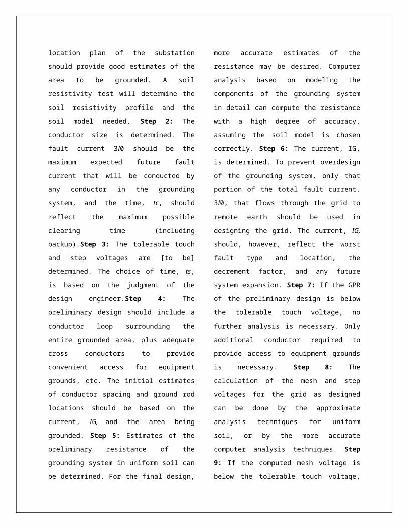
location plan of the substation
should provide good estimates of the
area to be grounded. A soil
resistivity test will determine the
soil resistivity profile and the
soil model needed. Step 2: The
conductor size is determined. The
fault current 3I0 should be the
maximum expected future fault
current that will be conducted by
any conductor in the grounding
system, and the time, tc, should
reflect the maximum possible
clearing time (including
backup).Step 3: The tolerable touch
and step voltages are [to be]
determined. The choice of time, ts,
is based on the judgment of the
design engineer.Step 4: The
preliminary design should include a
conductor loop surrounding the
entire grounded area, plus adequate
cross conductors to provide
convenient access for equipment
grounds, etc. The initial estimates
of conductor spacing and ground rod
locations should be based on the
current, IG, and the area being
grounded. Step 5: Estimates of the
preliminary resistance of the
grounding system in uniform soil can
be determined. For the final design,
more accurate estimates of the
resistance may be desired. Computer
analysis based on modeling the
components of the grounding system
in detail can compute the resistance
with a high degree of accuracy,
assuming the soil model is chosen
correctly. Step 6: The current, IG,
is determined. To prevent overdesign
of the grounding system, only that
portion of the total fault current,
3I0, that flows through the grid to
remote earth should be used in
designing the grid. The current, IG,
should, however, reflect the worst
fault type and location, the
decrement factor, and any future
system expansion. Step 7: If the GPR
of the preliminary design is below
the tolerable touch voltage, no
further analysis is necessary. Only
additional conductor required to
provide access to equipment grounds
is necessary. Step 8: The
calculation of the mesh and step
voltages for the grid as designed
can be done by the approximate
analysis techniques for uniform
soil, or by the more accurate
computer analysis techniques. Step
9: If the computed mesh voltage is
below the tolerable touch voltage,

the design may be complete (see Step
10). If the computed mesh voltage is
greater than the tolerable touch
voltage, the preliminary design
should be revised (see Step 11).Step
10: If both the computed touch and
step voltages are below the
tolerable voltages, the design needs
only the refinements required to
provide access to equipment grounds.
If not, the preliminary design must
be revised (see Step 11). Step 11:
If either the step or touch
tolerable limits are exceeded,
revision of the grid design is
required. These revisions may
include smaller conductor spacing,
additional ground rods, etc. More
discussion on the revision of the
grid design to satisfy the step and
touch voltage limits is given in
[Section 2.12] Step 12: After
satisfying the step and touch
voltage requirements, additional
grid and ground rods may be
required. The additional grid
conductors may be required if the
grid design does not include
conductors near equipment to be
grounded. Additional ground rods may
be required at the base of surge
arresters, transformer neutrals,
etc. The final design should also be
reviewed to eliminate hazards due to
transferred potential and hazards
associated with special areas of
concern. The block diagram in Figure1 illustrates the procedure to
design the ground grid.
Figure 1: Design Procedure Block
Diagram.
Design Modifications: If the
calculated grid mesh and step
voltages are greater than the
tolerable touch and step voltages,
then the preliminary design needs to
be modified. The following are
possible remedies:
(a) Decrease total grid resistance:
If the total grid resistance is
decreased, the maximum GPR is
decreased; hence the maximum
transferred voltage is decreased. An
effective way to decrease the grid
resistance is to increase the area
occupied by the grid. Deep driven
rods or wells can be used also if
area is limited.
(b) Decrease grid spacing’s:
Decrease the mesh size by increasing
the number of parallel conductors in
each direction. Dangerous potentials
within the substation can be
eliminated. For the perimeter, a
ground conductor can be buried
outside the fence, or increase the
density of ground rods at the
perimeter.
(c) Increase the thickness of the
surface layer: a practical limit may
be 6 inches.
(d) Limit total fault current: If
feasible, limiting the total fault
current will decrease the GPR and
gradients in proportion.
(e) Diverting greater part of the
fault current to other paths
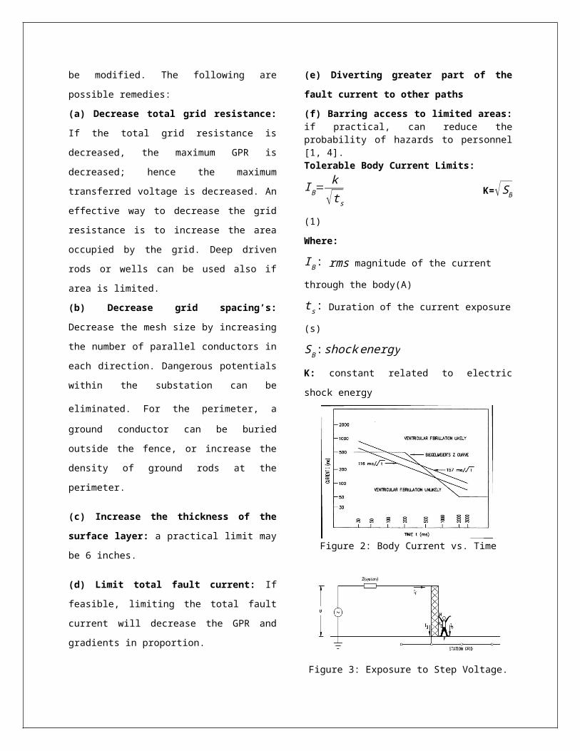
(f) Barring access to limited areas:if practical, can reduce theprobability of hazards to personnel[1, 4].Tolerable Body Current Limits:
IB=k
√ts K=√SB
(1)
Where:
IB: rms magnitude of the current through the body(A)
ts: Duration of the current exposure(s)
SB:shockenergyK: constant related to electric
shock energy
Figure 2: Body Current vs. Time
Figure 3: Exposure to Step Voltage.

VTh
ZTh+RB
(2)
Where: VTh: Thevenin voltage
between terminal H and F (V)
ZTh: Thevenin impedance from point Hand F (Ω)
RB: Body Resistance (Ω)
Figure 4: Step Voltage Circuit
The Thevenin equivalent impedance
for the touch voltage accidental
circuit is:
ZTh=Rf
2
(3)
Figure 4: Exposure to Step Voltage.
Figure 5: Step Voltage Circuit
The Thevinin equivalent impedance
for the step voltage accidental
circuit is: ZTh=2Rf
(4) Where: Rf: ground resistance of
one foot
In circuit analysis, a human foot is
represented as a conducting metallic
disc and resistance of the shoes and
socks are neglected.
The equation to calculate the ground
resistance Rfis:
Rf=ρ4b
(5) Where: ρ: Earth’s resistivity (Ω-m)
b: Radius of a foot taken as a metallic disk (typically 0.08m) Using a circular plate of
approximately 0.08m, the equations
for Zth is:
For touch voltage accidental circuit
Zth=1.5ρ (6)
And for step voltage accidental
circuit

Zth=6ρ (7)
Conductor Sizing:
The symmetrical current can becalculated based on the material andthe size of the conductor used as:
I=Amm2√(TCAP.10−4
tcarρr )ln(K0+Tm
K0+Ta )(8)If the conductor size is given inkcmil, the equation becomes:I=
5.07.10−3Akcmil√( TCAPtcarρr )ln(K0+Tm
K0+Ta )(9)Where I: rms current (kA) Amm2: Conductor cross section (mm2) Akcmil: Conductor cross section(kcmil) Tm: Maximum allowabletemperature (°C) Ta: Ambient temperature(°C) ar:Thermal coefficientof resistivity at referencetemperature Tr (1/°C) ρr: Resistivity of theground conductor at referencetemperature Tr(μΩ-cm) tc : Duration of current(s) K0: equals 1/ α0 or (1/αr)- Tr (°C)
TCAP : thermal capacity per unit
volume(J/𝑐m2. °C)
IMPROVING EARTHING SYSTEM: Whether improving an existing system or ensuring that a new system the following points can be used to improve the final system
performance. Low soil resistivity is to some extent tied to an electrolytic mechanism with such characteristics as - chemicals composition, soil ionization, homogenous grain size and even distribution, playing a large determinant due to the effect on the retention of soil moisture and packing density in contact with the electrode.
Table1 - Variations in resistivitywith temperature for a mixture ofsand and clay with a moisturecontent of about 15% by weight
Obtaining a satisfactory earth
resistance has always been a problem
in areas of poor soil conductivity.
Most National and International

Lightning Protection codes require
an earth resistance of 10 ohms or
less to be provided for a lightning
protection installation.
The laying of copper grids, tapesand rods alone may not alwaysprovide the desired result. Even ifcopper materials are used and thespecified resistance level isachieved, seasonal fluctuations insoil moisture can cause variationsin the resistance level. In dryperiods it is possible for the earthresistance to rise above the asinstalled level. This variation isearth resistance can affect theintegrity of the entire lightningprotection system. Suitableelectrical resistance cannot besimply and economically attained bythe installation of a standard earthgrid, an application of earthenhancing compound will assist. Suchcompounds consists of chemicalsolutions of good electricalconductivity which, when mixed withwater and poured onto the Earthinggrid and surrounding soil become agelatinous mass, forming an integralpart of the overall Earthing system.Field tests have shown dramaticimprovement in earth resistance whensuch compounds are added to highresistivity soil such as shale orsilica. Erica supplies two suchcompound; Earth Gel and GEM. EarthGel comes in kit form and comprisesof two 5kg parts consisting of acopper solution in one and a complex
mixture of chemicals which assistsin advantage with this compound isthat it will not wash or leach awaylike many other resistance improvingmixtures. This obviates the need toredoes the area with time.
EXAMPLES OF ACHIEVING SUITABLEEARTHING INSTALLATIONS USINGCHEMICAL ADDITIVES:
First obtain a rough determinant of
the earth resistivity by driving a
test earth rod. By referring to
previous tables an estimate of the
likely number of rods which will be
required can be obtained. It may
only be necessary to drive in one
copper (or more generally a steel
core/copper clad) rod. Dig a hole
500mm deep x 200mm diameter around
it and apply approximately 2kg of
each part of a kit of compound to
fill the cavity. Allow 30 minutes
for the compound to gel, and measure
the resistance. If the resistance is
not low enough, dig a trench 500mm
deep x 200mm wide and approximately
5 meters long. Lay a length of
copper tape (approximately 3 inch
wide x 0.1 in thick) into tins
trench, again applying approximately
3kg of each part of a kit of
compound. Allow time for the
compound to gel and re measure. If

necessary, repeat the procedure
laying tapes radially outwards from
the main electrode until a
satisfactory resistance is obtained.
The earth tapes should be replaced
as far apart as possible from one
another and securely connected to
the main earth rod.
Example 2:
In rocky/shale ground the best
results are obtained by digging a
trench approximately 500mm deep and
200mm wide and laying the earthing
material in the bottom and covering
it with approx 100mm of fine soil or
sand. Solution 1 is then poured on
and when it has been absorbed.
Solution 2 is added in a similar
manner. The entire trench is then
backfilled.
Example 3:
If a good resistance is required in
solid rock or heavy shale, one
approach is to drill a hole
approximately 75mm wide and 250mm
deep and insert the copper rod. Then
mix solution 1 and 2 together and
pour the mixture down the hole. In
effect this will provide a
conductive medium of 250 mm x 75mm
as an earth. If a suitable
resistance is not obtained repeat
the above procedure using multiple
earth rods and bond together using
copper tape lay in a trench.
Example 4:
With existing earth mats expose as
much of the grid as possible. Apply
Solution 1 wait until it is
absorbed, apply solution 2 and then
back fill the entire grid.
NOTES ON THE APPLICATION OF CHEMICAL
COMPOUNDS
Before applying the compound,
saturate the ground with water to
assist with the distribution of the
chemicals. It must be stressed that
every application is different and
therefore results will differ
accordingly. Generally speaking, one
kit will be sufficient to produce a
satisfactory earth resistance over a
5 meter length of earth tape in the
worse soil conditions. In better
soil conditions, one such kit will
generally be adequate to cover 5
meters of earth tape.

Measures for Reducing the ImpulseImpedance: Whilst the actualpercentage improvement gained willbe highly dependent upon localconditions, the following measurescan be used to reduce the impulseimpedance of earthing systems.
• The use of flat tape rather than
circular conductors. For a given
cross-section of conductor, this
increases the surface area in
contact with the ground, and hence
increases capacitive coupling and
reduces the overall contact
resistance. It also reduces the high
frequency resistance due to skin
effects. Flat tape also tends to
have a lower inductance per meter
than a circular conductor of
equivalent cross-sectional area.
• The use of short-length radial
conductors bonded at the injection
point, rather the single long length
conductor. This produces the effect
allaying a number of conductors in
parallel.
• Terminating radial conductors with
vertical electrodes. This measure is
more effective in low to medium soil
resistivity.
• Using large bending radii when
changing die direction of horizontal
conductors. Sharp bends tend to
increase the inductance
• Conductors. Lowering the soilresistivity reduces the resistivecomponent of the impedance and theuse of earth enhancing compounds toimprove the soil resistivity in theproximity of the hence improves thetotal impedance.
CONCLUSION
Substation grounding is a crucial
part of substation design. The
design has to be both safe and
reliable. There are many steps to
design a safe and effective grid.
Hand calculations may be a tedious
and difficult. Doing calculations
and modifications to the design can
be a long process. Computer programs
have been developed to make the
substation grounding design easier,
and more accurate.
This paper provides an overview of
substation grounding and the most
essential elements of a substation
grounding grid design based on the
IEEE STD and improving it .This
paper provides equations that are
involved with a grid design. Finally
an equation is provided using real

world data. This example was
designed to meet the design criteria
for a safe ground grid.
• The measures to improve the
earthing system of substation was
Done successfully.
• The need and importance of
improving earthing system is
proposed.
• In this paper I have to suggest
many ways for the improvement of
earthing system and to overcome the
difficulties in earthing system by.
a) Providing earth pits at proper
position.
b) Always provide water to earth pit.
c) Use Bentonate powder, soft coal,
black salt.
ACKNOWLEDGMENTThis project was done during my Mtech in
electrical engineering in India in Baharti
Vidyapeeth University pune.
REFERENCES
[1] Design Guide for Rural
Substations”, Rural Utilities
Service. United States Department of
Agriculture. June 2001.
[2] Gonen, Turan. “Electric Power
Distribution System Engineering.”
CRC Press. 2008.
[3] Gonen, Turan. “Electric Power
Transmission System Engineering:
Analysis and Design.” CRC Press.
2009.
[4] "IEEE 80-2000 IEEE Guide for
Safety in AC Substation Grounding."
[5] "IEEE 81-1983 IEEE Guide for
Measuring Earth Resistivity, Ground
Impedance, and Earth Surface
Potentials of a Ground System.”
[6] Markovic, D. Miroslav.
“Grounding Grid Design in Electric
Power Systems.” TESLA Institute,
1994.
[7] NFPA 70-2008. National
Electrical Code. 2008.
Copyright © 2022 FDOKUMEN