Upgrade Admin Substation at the Durban Container Terminal ...
Upload
khangminh22Category
view
1download
0
Presented by:
Jonathan R. SantiagoProtection Engineering Manager
INSTITUTE OF INTEGRATED ELECTRICAL ENGINEERS OF THE PHILS., INC
Power System Protection Application (CBF &
Substation Bus Protection)

Overview
Power System Components

What is Protective Relay?
In electrical engineering, a protective relay is a relay device designed to
trip a circuit breaker when a fault is detected.
sensors current
voltage
A protection device does not
prevent the fault from occurring,
but limits the consequences...
Trippingcoil
Detect and isolate the fault
Preserve continuity of supply
Measure
Compare
Decide

Power System Protection - Basic Requirements
1. Selectivity or Discrimination
a. Time grading
b. Unit System
2. Stability
3. Speed
4. Sensitivity

Basic Components of Protection
1. Voltage and Current Transformers
Voltage Transformer Current Transformer
P = Us2 / Z and Is = Us / Z P = Z x Is2 and Us = Z x Is
Never connect the VT in short-circuit Never leave the CT in open-circuit
“CT star point should always towards the
protected zone”

CT Protection Unit

Current Transformers

Voltage Transformers

Basic Components of Protection
2. Relays
3. Fuses
4. Circuit Breakers
5. DC Batteries
Breaker Failure & Substation Bus Protection
1. Breaker Failure Protection = 50BF
2. Stuck Breaker Protection = 51B
3. Differential Busbar Protection = 87B
4. Differential TEE Protection = 87TEE
5. Pole Discrepancy Protection = PD

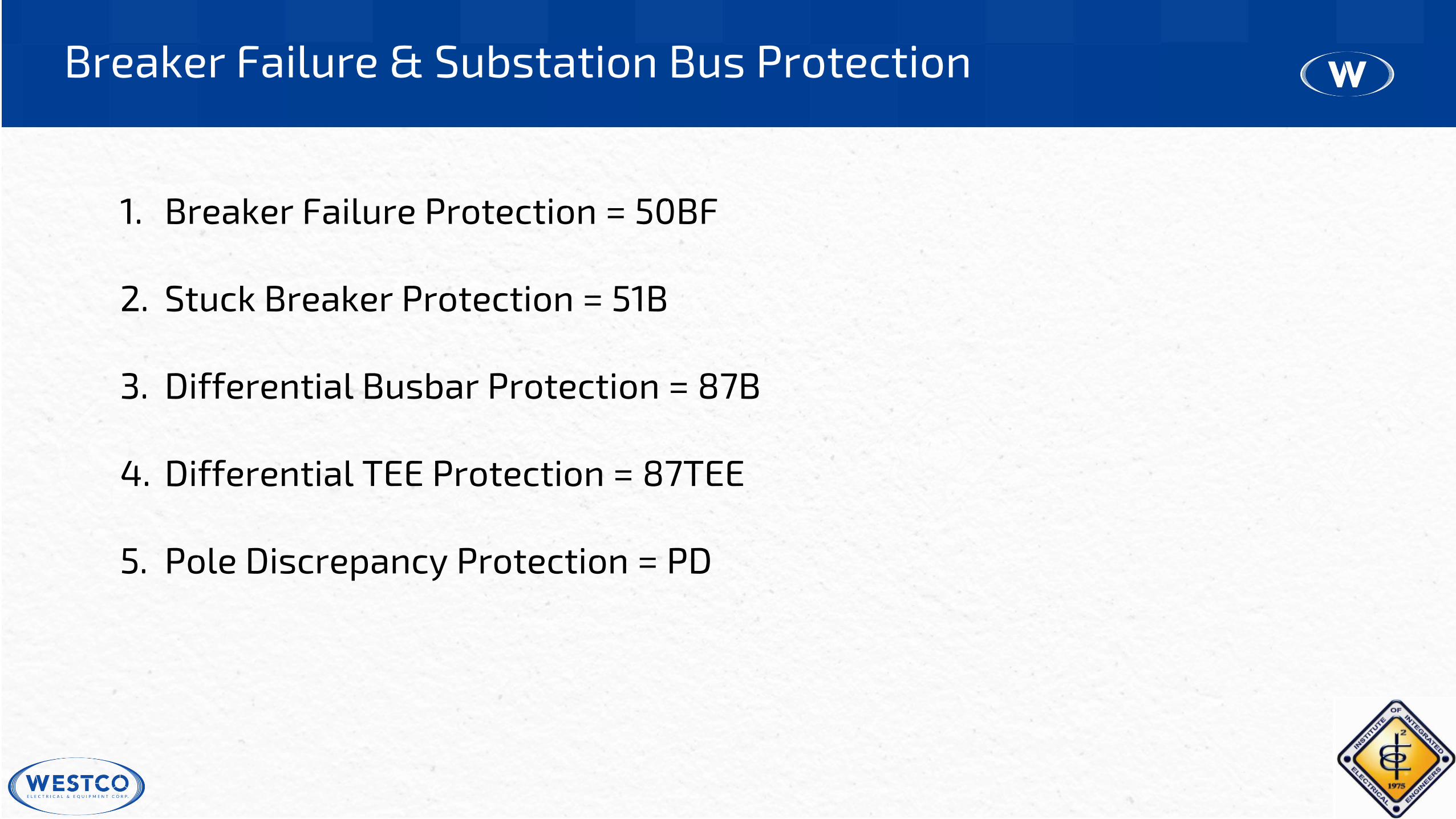
CB Trip Failure

UPPER BUS
LOWER BUS

UPPER BUS
LOWER BUS


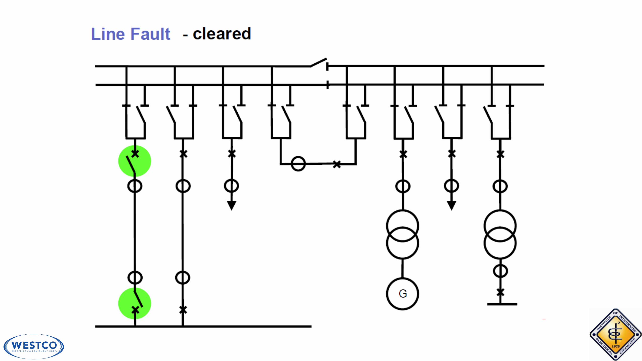


1. Supervision of the feeder current after a tripping command
OR
2. Supervision of the CB auxiliary contacts after a tripping command
OR
3. Supervision of the feeder current (with the BBP measurement algorithm) after a
tripping command (only applicable if the BFP is installed in the BBP system)
– BBP unbalancing
Breaker Failure Protection Solutions


➢ standard BFP application
➢ for line, transformer, generator, generator-transformer, reactors and coupler CB’s
➢ for all voltage levels and switchgear configurations
➢ overcurrent settable independently for all feeders (depending on the minimum
feeder short current)
➢ operation independent on the CB auxiliary contacts (aux. contacts are a week part
of the protection chain)
➢ for single, double and three phase auto-reclosure (tripping), (phase segregated
starting inputs)
➢ for detection of evolving faults (phase segregated timers for t1)
➢ remote tripping signal settable after timer 1 or timer 2
➢ advanced trip redirection functionality in case of CB SF6 under pressure condition
Application & Features of Solution 1

➢ applicable for very low fault currents (e.g. generator reverse power function)
➢ remote tripping signal settable after timer 1 or timer 2
➢ advanced trip redirection functionality in case of CB SF6 under pressure condition
➢ very good addition to solution 1
➢ no overcurrent (fault current) supervision
➢ the starting signal must be switch off by the CB “OFF” aux. contact to prevent an
unwanted trip
➢ operation dependent on the CB auxiliary contacts (aux. contacts are a week part of
the protection chain
➢ not applicable for single and double phase auto reclosure (tripping)
Application & Features of Solution 2


➢ applicable as basic BBP coupler functionality for the detection of faults between
coupler CB and CT (coupler function – CB reclaim time)
➢ not applicable for line, transformer, generator, generator-transformer, reactors
feeders in HV system
➢ Overcurrent (fault current) supervision depending on the BBP differential current
setting (high short current required)
➢ not applicable for single and double phase auto-reclosure (tripping)
➢ the starting signal must be switch off by the CB “OFF” aux. contact to prevent an
unwanted trip to the CB after timer 1
➢ operation dependent on the CB auxiliary contacts (aux. contacts are a week part
of the protection chain)
➢ no trip-redirection functionality in case of CB SF6 under pressure condition
➢ remote tripping signal fixed to timer 1
Application & Features of Solution 3

2. Stuck Breaker Protection = 51B

3. Differential Busbar Protection = 87B
Single Busbar with Section Coupler ( 1 coupler 2 CT)

4. Differential Protection Measuring Principle
Kirchhoffs 1st Law: Node Rule
The vector sum of all currents must be zero
I1 + I2 + I3 = Σ I = 0
I1
I3
I2

4. Differential Protection Measuring Principle
Kirchhoffs 1st Law: Node Rule
I1 + I2 + I3 = Σ I
if ≠ 0 or
if Σ I > differential current setting
Fault on the Busbar
Trip Circuit Breaker
Trip Busbar Protection
I1
I2
I3

Single Busbar with Section Coupler ( 1 coupler 1 CT)

Single Busbar with Section Coupler ( 1 coupler CT)

Single Busbar with Section Coupler ( 1 coupler CT)

Single Busbar with Section Coupler ( 1 coupler CT)

Single Busbar with Section Coupler ( 1 coupler CT)

How can a busbar protection system detect a fault between the Coupler
Circuit Breaker and Current Transformer?
➢ By deactivating of the current measurement in the coupler in case of
Internal BBP tripping signal (= coupler blocking)
Coupler Functions I


Differential Current Supervision
Which failures in the CT circuits can the Differential current supervision
detect?
➢ a missing CT input (e.g. CT circuit not connected to the system
➢ a wrong CT ratio
➢ a wrong current direction
The “differential current alarm” is very important and must not be ignored
by the operating personnel.

Double Bus Single Breaker Scheme
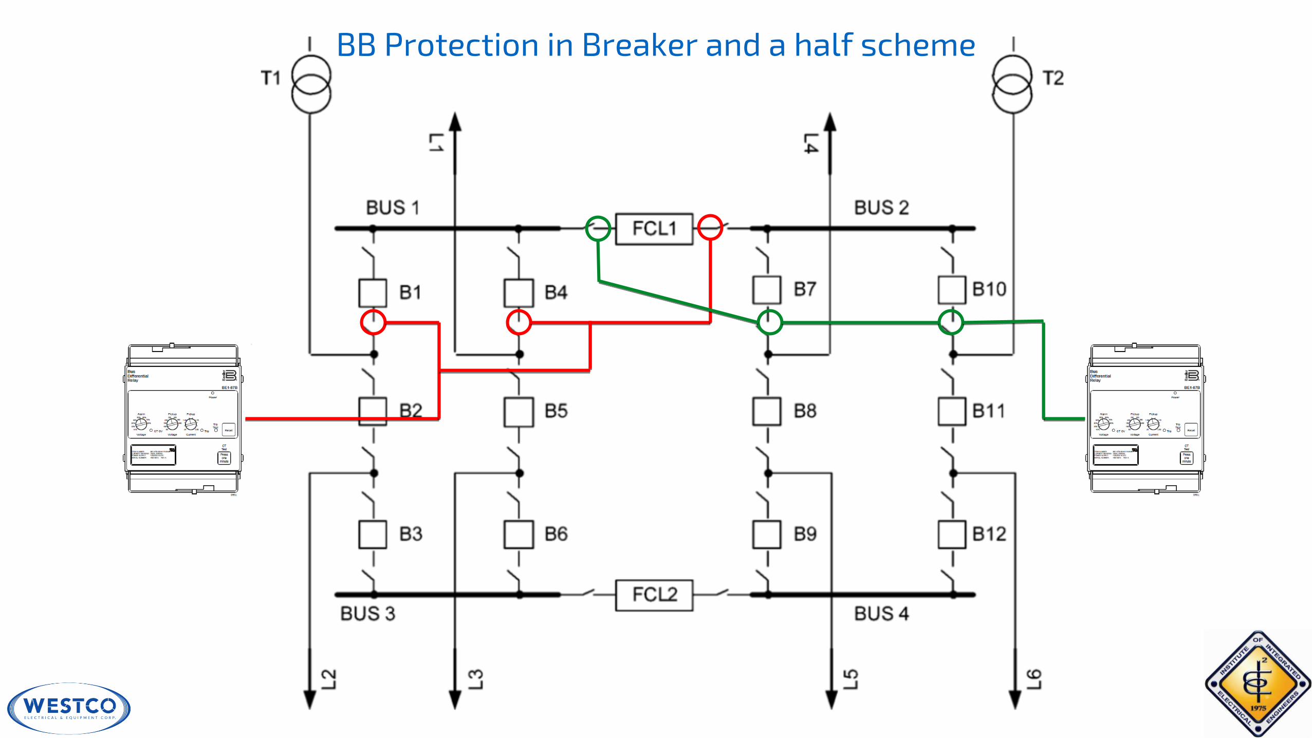
BB Protection in Breaker and a half scheme

87TEE-1
87TEE-2
4. Differential TEE Protection = 87TEE

5. Pole Discrepancy Protection
LOGIC


BE1-11MULTIFUNCTION PROTECTION SYSTEM
Presented by:
Chip ChristmannProtection Operations Manager

BE1-11
Multifunction Protection System

BE1-11 Protection System

• The most user friendly settings/logic in a distribution relay
• Sophisticated simplicity of programming for your needs
• Settings software program can be used for all relay types
• Numerous application templates available (can be edited)
• Firmware upgrade kits available for field upgrades
• No field hardware changes needed
• Platform flexibility ensures unlimited future upgradability with proper hardware at initial purchase
• Operational training from Basler application engineering and technical support is no cost
• We believe in empowering you to manage your relays and support you to do so
Why you need the BE1-11f

• One software program for settings (F, T, I, G, M, D)
• One logic library - visually document your logic!
• Many AC elements shared by all applications
• Standardization of Protection and Control
• Same algorithms, elements do not need to be re-calculated, no hidden pitfalls, same coordination curves, no need to re-do your coordination
• Communications map is identical for all relays (11f, 11t, 11g, etc.) all in the same location
• SCADA integrators have 1/5 the work since they don’t have to re-map
One Relay Does It All

BE1-11f – Feeder
Features/Functions:• Recloser (79)
• Voltage (24, 25, 27P, 27X, 59P, 59X, OV/UV, Table Curves)
• Current (50, 50BF, 51, 67, Table Curves)
• Frequency (81)
• Power (32)
• Impedance (21)
• Thermal (49RTD)
• Sensitive Earth Fault (SEF)
• Remote Analog Inputs and Outputs
• Selectable I/O – 4, 7, or 10 Inputs and 6 or 9 Outputs
• Unbalance Mode to 50 and 51 elements

BE1-11t – Transformer
Features/Functions:• Current (50, 50BF, 51, 67, 87, 87N, Table Curves)
• Voltage (24, 25, 27P, 27X, 59P, 59X, OV/UV, Table Curves)
• Frequency (81)
• Impedance (21)
• Thermal (49RTD)
• Recloser (79)
• Control (43, 62, 86, 101)
• Sensitive Earth Fault (SEF)
• Remote Analog Inputs and Outputs
• Selectable I/O – 7, or 10 Inputs and 6 or 9 Outputs
• Through-Fault Monitor
• All 2-Winding Applications

BE1-11i – Intertie
Features/Functions:• Power (32)
• Voltage (24, 25, 27P, 27X, 59P, 59X, 78V, OV/UV, Table Curves)
• Current (50, 50BF, 51, 67, Table Curves)
• Frequency (81)
• Thermal (49RTD)
• Recloser (79)
• Control (43, 62, 86, 101)
• Sensitive Earth Fault (SEF)
• Remote Analog Inputs and Outputs
• Selectable I/O – 4, 7, or 10 Inputs and 6 or 9 Outputs

BE1-11g – Generator
Features/Functions:• Voltage (24, 25, 27P, 27X, 59P, 59X, 78V, OV/UV, Table
Curves)
• Current (50, 50BF, 51, 67, 87, 87N, Table Curves)
• Impedance (21, 40Z, 78OOS)
• Control (25A, 43, 62, 86, 101)
• Frequency (81)
• Power (32, 40Q)
• Thermal (49RTD)
• Sensitive Earth Fault (SEF)
• Remote Analog Inputs and Outputs
• Selectable I/O – 4, 7, or 10 Inputs and 6 or 9 Outputs
• Unbalance Mode to 50 and 51 elements
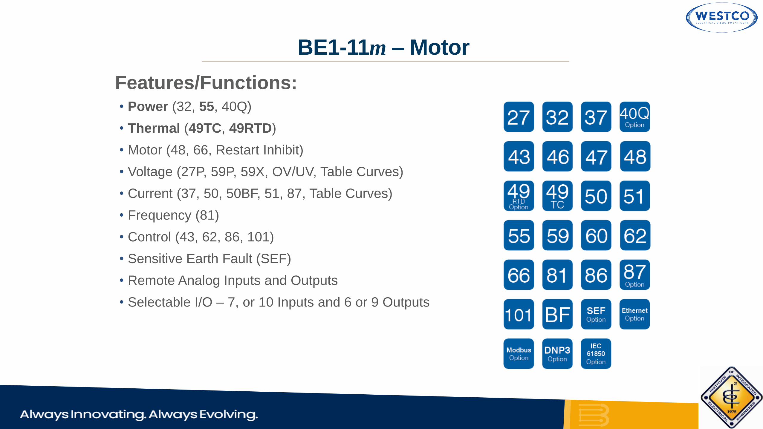
BE1-11m – Motor
Features/Functions:• Power (32, 55, 40Q)
• Thermal (49TC, 49RTD)
• Motor (48, 66, Restart Inhibit)
• Voltage (27P, 59P, 59X, OV/UV, Table Curves)
• Current (37, 50, 50BF, 51, 87, Table Curves)
• Frequency (81)
• Control (43, 62, 86, 101)
• Sensitive Earth Fault (SEF)
• Remote Analog Inputs and Outputs
• Selectable I/O – 7, or 10 Inputs and 6 or 9 Outputs

BE1-11d – DC Power
Provides a 2-3 component solution
• (1) low voltage cabinet mounted BE1-11d relay
• (1 or 2) IT-D high voltage cabinet mounted modules

Basler DC System Components
BE1-11d
•Based upon standard BE1-11
•CT/PT inputs modified to fiber
IT-D
• 2 channels per module for voltage or current
•Universal hardware accepts 100-2,000 Vdc for voltage measurement
•Or 25-100mV from the shunt for current measurement
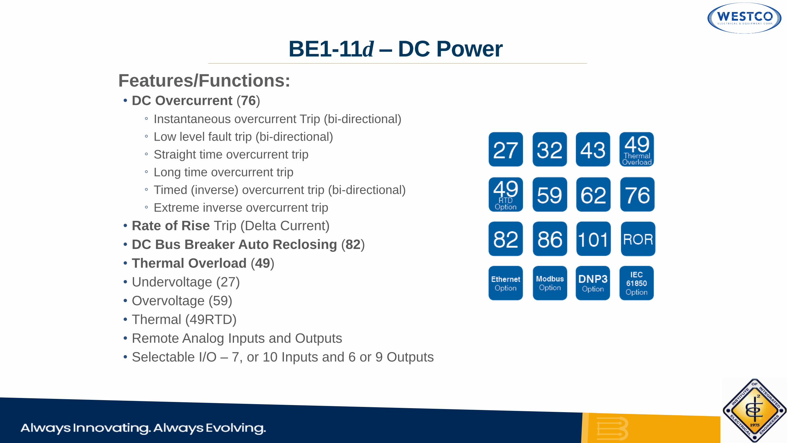
BE1-11d – DC Power
Features/Functions:• DC Overcurrent (76)
◦ Instantaneous overcurrent Trip (bi-directional)
◦ Low level fault trip (bi-directional)
◦ Straight time overcurrent trip
◦ Long time overcurrent trip
◦ Timed (inverse) overcurrent trip (bi-directional)
◦ Extreme inverse overcurrent trip
• Rate of Rise Trip (Delta Current)
• DC Bus Breaker Auto Reclosing (82)
• Thermal Overload (49)
• Undervoltage (27)
• Overvoltage (59)
• Thermal (49RTD)
• Remote Analog Inputs and Outputs
• Selectable I/O – 7, or 10 Inputs and 6 or 9 Outputs

AC to DC Conversion
AC DC

Optional RTD Module
Features/Functions:
• Reporting and alarms
• Notifications of system status through BE1-11 protection system
• 12 RTD Inputs
• 4 Analog Inputs
• 4 Analog Outputs
• Connect up to 2 RTD modules per BE1-11 protection system
• Ethernet or RS-485 communications

System Interface Software:
•Metering explorer
◦Extensive real time and reporting capabilities.
•Settings explorer
◦ Quick and confident programming.
◦ System summary
◦ Compare settings
◦ Visual logic and logic libraries
◦ Compressed print preview
BESTCOMSPlus®

Metering of all measured and calculated values.
Primary and secondary metering
Phasor diagrams
Configurable
BESTCOMSPlus® – Analog Metering
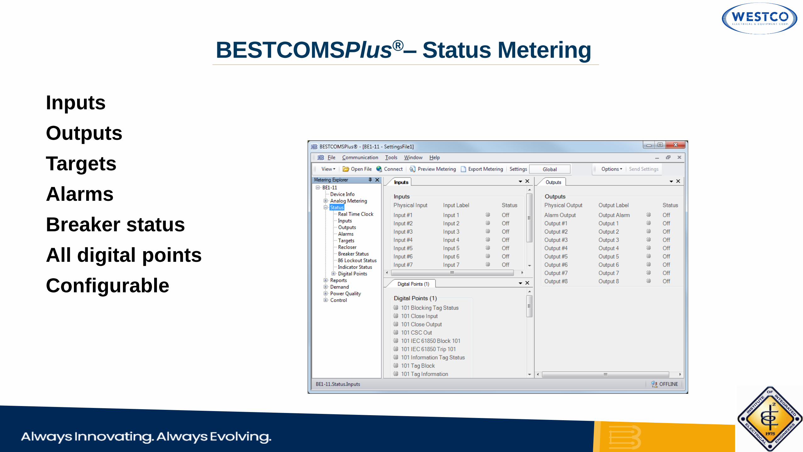
Inputs
Outputs
Targets
Alarms
Breaker status
All digital points
Configurable
BESTCOMSPlus®– Status Metering

Sequence of events
Fault records
Security log
Load profile
Breaker monitor
Differential (g, m, t)
Motor starts (m)
Transformer damage (t)
BESTCOMSPlus® – Reports
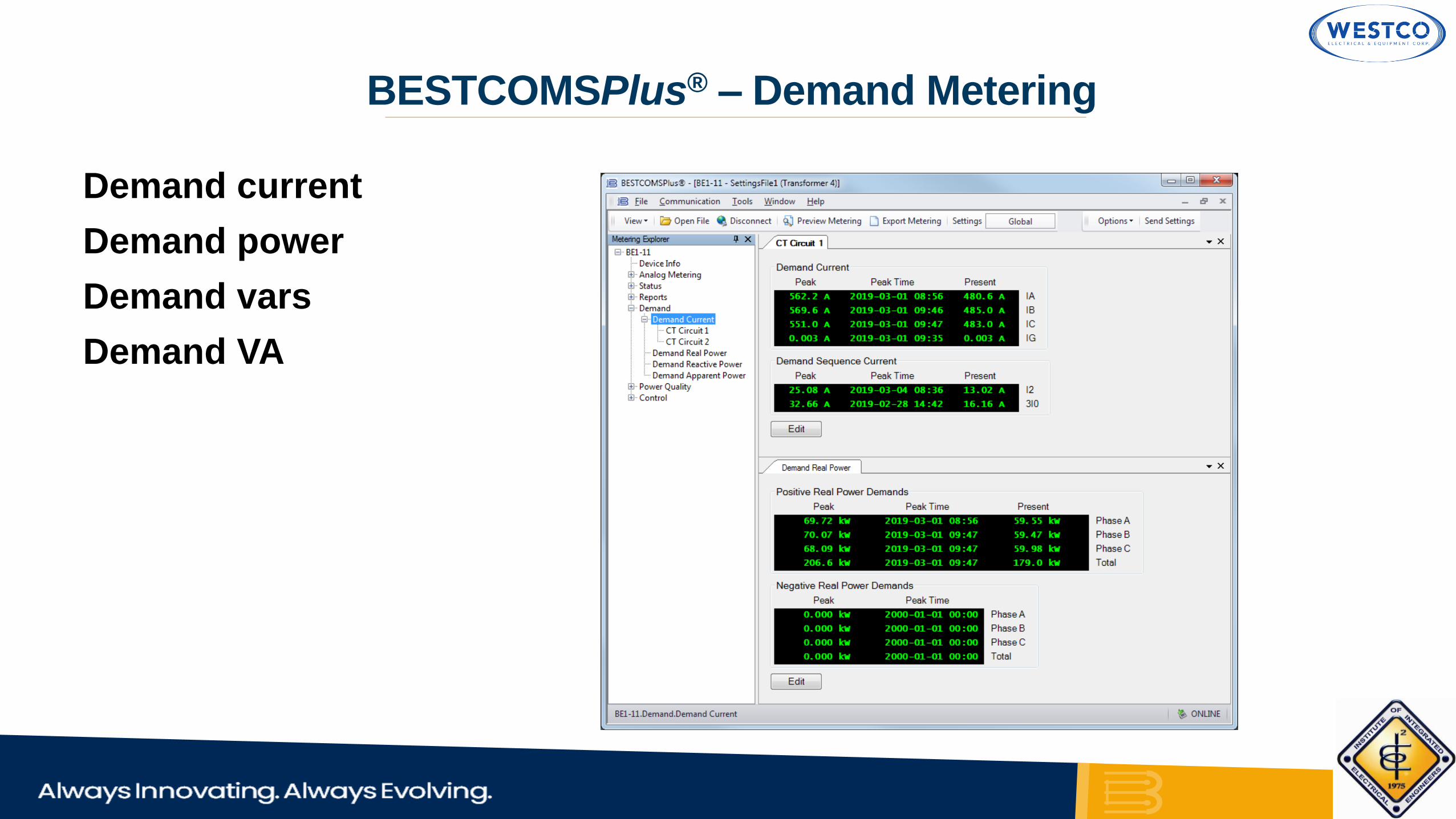
Demand current
Demand power
Demand vars
Demand VA
BESTCOMSPlus® – Demand Metering

Voltage
Distortion
Dip/Swell
Harmonics
BESTCOMSPlus® – Power Quality

Virtual switches
Breaker control switch
Output override
Setting group control
BESTCOMSPlus® – Control

Intuitive settings
Meaningful labels
Built in graphs
BESTCOMSPlus® – Settings

Formatted settings printout
Easy to read
Show only enabled elements
BESTCOMSPlus® – Settings

System summary
Easy confirmation of relay setting
Enabled and pickup set
No pickup set
Pickup set but mode disabled
Disabled
BESTCOMSPlus® – Settings

Programmable logic
Powerful tool within BESTCOMSPlus®
featuring innovative and comprehensive logic schemes.
Preprogrammed BESTlogic™Plus schemes provide a starting point for customer applications.
User friendly interface for customizing schemes
BESTlogic™Plus

Large selection of logic elements
Drag and drop logic
Visual connectivity
Self documentation
User annotations
On-line logic library
BESTlogic™Plus

Logic file printout
Provides a means of making logic available on location without a computer.
BESTlogic™Plus

Offline
Logic
Simulator
BESTlogic™Plus

• Modbus® available over Ethernet and RS-485
• DNP3 available over Ethernet and RS-485
• IEC 61850
Communications Protocols

• Easily configure and document IEC 61850 between devices from several suppliers with BEST61850™.
• Reduce engineering effort with intuitive drag and drop graphical user interface.
• Capable of Goose network containing greater than 255 devices
• Alarm on the loss of any device subscribed to IEC 61850
• Supports configurable buffered reports
IEC 61850

Half-rack and J case options*
Half-rack is draw out
J case is plug out
*Half-rack not available on BE1-11m,BE1-11t, and BE1-11d.
Hardware
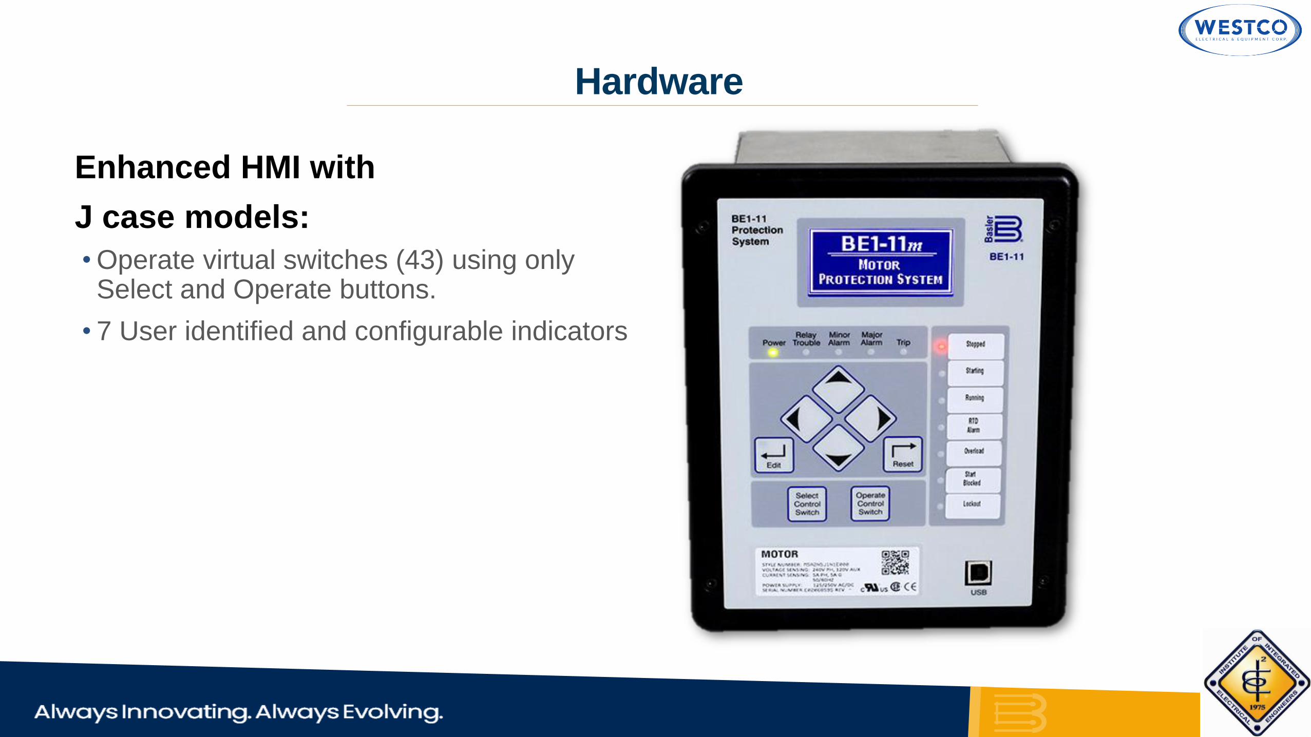
Enhanced HMI with
J case models:
•Operate virtual switches (43) using only Select and Operate buttons.
• 7 User identified and configurable indicators
Hardware

Rear connections
Hardware
Half-Rack Case (F, I, G)
J Case (F, I, G, M, T) J Case (D)

RTD Module
• 12 RTD inputs: 3-wire or 2-wire
• Four analog inputs
• Four analog outputs
BE1-11 – Hardware

• Feeder and Transformer Protection in one box with the enhanced option (sync-check, recloser, directional overcurrent, and differential plus others)
• Competitors do not have these functions in the same box
• Both Half Rack and S1 case sizes for adapting to any mounting environment
• USB and Ethernet port for higher bandwidth, not RS-232 serial port 1st generation relay
• 21 Distance protection functions in a feeder relay when circuit impedance increases or decreases beyond set value
• Under/Over voltage inverse time elements standard (important for retrofitting electromechanical or single function solid state relays) Those device had inverse curve options, most digital relays do not have this. Or they have to go to a $5K+ relay to have this functionality.
• BE1-11 is roughly half the price of the competitor with these features.
Distinguishing features

• We make overall relay solutions easy to implement and understand
• We want our relays to reflect customers needs
• Our goal is to make relays inherently useful to you and customizable
• Our visual logic makes our Distribution Recloser very easily customized for those wanting to make small changes - We learned this from our strong control background
• Visual logic with feedback loops and logic that is not linear/straight-forward is much easier to see the concept shown vs. a crazy long Boolean logic stream
• The offline logic simulator is available free of charge with the free software to prove out the logic files performance as desired.
• Open universal protocols in the BE1-11 relays – we do not lock you into a monopoly like some relay vendors with proprietary protocols that make switching from their relay system very costly in your future
• Proprietary protocols eliminate any future other vendors better solutions within your system - You are stuck with “their” way
• We don’t back you into an expensive future corner with our products
Distinguishing features
• Basler Electric Reliability and Experience
• More than 75 Years of Longevity in Power Systems
• High Quality Relays Made in the USA – Dual Manufacturing in Texas and Illinois
• Advanced Cybersecurity-Utility Grade Cybersecurity Protection
• BESTCOMSPlus Windows PC Software Simplifies Relay Settings and Logic Notation
• One multifunction protection system for all applications - Easiest learning curve- Most flexible
• 2 Week Lead Time – Avoid Production Delays
Why to buy

WESTCO | CORPORATE PROFILE
Partners
The brain-child of Engr. Rodolfo R.
Peñalosa, PAMAVTech specialises in
competency-based and hands-on
technical trainings for practicing
professionals
A trading corporation established in 1990
to handle industrial electro-mechanical
and electrical devices

Questions?
8F, 68 Kalayaan VCP Building, 68 Kalayaan AvenueTeachers’ Village West, Quezon City 1101
(632) 8365-0068
[email protected]@westco-phil.com
www.westco-phil.com
Address:
Tel No.:
Email:
Website:
Copyright © 2022 FDOKUMEN