Network analysis and building construction - Academic Journals
Upload
khangminh22Category
view
0download
0
Standard
Disclaimer: This document is developed solely and specifically for use on Melbourne metropolitan tram network managed by Yarra Trams. It is not suitable for any other purpose. You must not use or adapt it or rely upon it in any way unless you are authorised in writing to do so by Yarra Trams. If this document forms part of a contract with Yarra Trams, this document constitutes a “Policy and Procedure” for the purposes of that contract. This document is uncontrolled when printed or downloaded. Users should exercise their own skill and care or seek professional advice in the use of the document. This document may not be current. Current standards are available for download internally from CDMS or from https://yarratrams.com.au/standards.
CE-019-ST-0007
1
20/03/2020
Infrastructure – Network Power – Substation – Design and Construction

Infrastructure – Network Power – Substation – Design and Construction
Document Number: CE-019-ST-0007 Document Author: Allen Tam Version: 1 Document Authoriser: Greg Williams Date Published: 20/03/2020 Doc ID: CDMS-313846386-5008
Page 2 of 47
Uncontrolled when printed
Table of Contents 1 PURPOSE ..................................................................................................................................................... 3
2 SCOPE ......................................................................................................................................................... 3
3 COMPLIANCE .............................................................................................................................................. 4
4 DC SUBSTATION REQUIREMENTS .............................................................................................................. 5
4.1 General principals............................................................................................................................... 5
4.2 Functional requirements .................................................................................................................... 7
4.3 Electrical performance requirements .............................................................................................. 13
4.4 Service performance requirements ................................................................................................. 14
4.5 Design requirements ........................................................................................................................ 16
4.6 Construction requirements .............................................................................................................. 26
4.7 Reliability, Availability, Maintainability and Safety (RAMS) requirements ...................................... 28
4.8 Documentation requirements.......................................................................................................... 29
5 DIAGRAMS AND GUIDANCE ..................................................................................................................... 33
5.1 Single line diagram of a DC traction substation ............................................................................... 33
6 RELATED LEGISLATION & DOCUMENTS ................................................................................................... 34
DOCUMENT VERSION CONTROL ...................................................................................................................... 36
APPENDIX A – GLOSSARY ................................................................................................................................. 37
APPENDIX B – TENDER REQUIREMENTS .......................................................................................................... 40
APPENDIX C – INNOVATION ............................................................................................................................. 42
APPENDIX D – ECO-FRIENDLY DESIGN ............................................................................................................. 43
APPENDIX E – ASSET NAMING CONVENTIONS ................................................................................................ 44
E1 Substations .............................................................................................................................................. 44
E2 Electrical sections .................................................................................................................................... 45
E3 Feeder cables ........................................................................................................................................... 45
E4 Substation equipment ............................................................................................................................. 46
APPENDIX F – DC REACTORS AND HARMONIC FILTERS ................................................................................... 47

Infrastructure – Network Power – Substation – Design and Construction
Document Number: CE-019-ST-0007 Document Author: Allen Tam Version: 1 Document Authoriser: Greg Williams Date Published: 20/03/2020 Doc ID: CDMS-313846386-5008
Page 3 of 47
Uncontrolled when printed
1 PURPOSE
The purpose of this standard is to specify the minimum requirements for design, construction, integration, commissioning and through life support of DC traction substations, which are to be installed on the Yarra Trams network.
The configuration, ratings and any other project specific equipment details shall be provided by Yarra Trams in the accompanying Scope of Works document.
2 SCOPE
The scope of this standard encompasses requirements for all new DC traction substations.
This standard does not apply retrospectively to existing DC traction substations on the Yarra Trams network. However, this standard is applicable if an existing DC traction substation is being altered, modified or replaced.
The scope of this document includes:
• All equipment which is located within the property limit of the DC traction substation;
• The 750 V DC positive system which includes the positive feeder cables, conduits and pits from the DC traction substation up to and including the cable termination at the interface with either the overhead wiring system (e.g. an overhead switch or feeder tap to trolley) or an existing cable termination (e.g. a pillar box or existing cable pit); and
• The DC negative return system which includes the negative feeder cables and buses, conduits and pits from the substation up to and including the rail bonds.
The scope of this document does not include:
• Positive feeder cable supports and protection (armour) at the point of termination as well as overhead switches and pillar boxes; and
• Remote negative cables (aerial or underground).
The requirements in this standard have been derived from the following sources:
• International and Australian Standards listed in section 6: Related legislation and documents
• Local subject matter experts within Yarra Trams and suppliers to Yarra Trams.
• PSU-2.6-SP-A-0001 rev 1.2 - General Design Requirements;
• PSU-2.6-SP-A-0016 rev 1.2 – DC Reactor and Harmonic Filter Specification;
• VRIOGS 010.3: Railway Traction Substation Design Standard Revision A 08/09/2009; and
• VRIOGS 010.4: Railway Traction Substation Construction Standard Revision A 08/09/2009.
The scope items outlined in Table 1, which were previously included in one or more of the above superseded documents, are excluded from this standard and have been addressed in other Yarra Trams documents as appropriate:
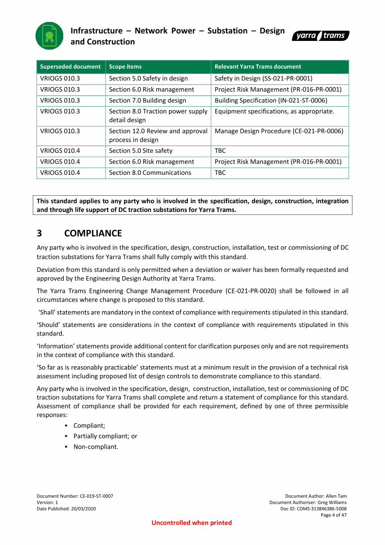
Table 1: Superseded documents – Excluded scope items
Superseded document Scope items Relevant Yarra Trams document
VRIOGS 010.3 Section 4.0 Traction power supply system design
Infrastructure - Network Power - Traction Power – Design and Construction (CE-023-ST-0032)
Infrastructure – Network Power – Substation – Design and Construction
Document Number: CE-019-ST-0007 Document Author: Allen Tam Version: 1 Document Authoriser: Greg Williams Date Published: 20/03/2020 Doc ID: CDMS-313846386-5008
Page 4 of 47
Uncontrolled when printed
Superseded document Scope items Relevant Yarra Trams document
VRIOGS 010.3 Section 5.0 Safety in design Safety in Design (SS-021-PR-0001)
VRIOGS 010.3 Section 6.0 Risk management Project Risk Management (PR-016-PR-0001)
VRIOGS 010.3 Section 7.0 Building design Building Specification (IN-021-ST-0006)
VRIOGS 010.3 Section 8.0 Traction power supply detail design
Equipment specifications, as appropriate.
VRIOGS 010.3 Section 12.0 Review and approval process in design
Manage Design Procedure (CE-021-PR-0006)
VRIOGS 010.4 Section 5.0 Site safety TBC
VRIOGS 010.4 Section 6.0 Risk management Project Risk Management (PR-016-PR-0001)
VRIOGS 010.4 Section 8.0 Communications TBC
This standard applies to any party who is involved in the specification, design, construction, integration and through life support of DC traction substations for Yarra Trams.
3 COMPLIANCE
Any party who is involved in the specification, design, construction, installation, test or commissioning of DC
traction substations for Yarra Trams shall fully comply with this standard.
Deviation from this standard is only permitted when a deviation or waiver has been formally requested and approved by the Engineering Design Authority at Yarra Trams.
The Yarra Trams Engineering Change Management Procedure (CE-021-PR-0020) shall be followed in all circumstances where change is proposed to this standard.
‘Shall’ statements are mandatory in the context of compliance with requirements stipulated in this standard.
‘Should’ statements are considerations in the context of compliance with requirements stipulated in this standard.
‘Information’ statements provide additional content for clarification purposes only and are not requirements in the context of compliance with this standard.
‘So far as is reasonably practicable’ statements must at a minimum result in the provision of a technical risk assessment including proposed list of design controls to demonstrate compliance to this standard.
Any party who is involved in the specification, design, construction, installation, test or commissioning of DC traction substations for Yarra Trams shall complete and return a statement of compliance for this standard. Assessment of compliance shall be provided for each requirement, defined by one of three permissible responses:
• Compliant;
• Partially compliant; or
• Non-compliant.
Infrastructure – Network Power – Substation – Design and Construction
Document Number: CE-019-ST-0007 Document Author: Allen Tam Version: 1 Document Authoriser: Greg Williams Date Published: 20/03/2020 Doc ID: CDMS-313846386-5008
Page 5 of 47
Uncontrolled when printed
4 DC SUBSTATION REQUIREMENTS
4.1 General principals
4.1.1 Design principles
4.1.1.1 All design activity shall be undertaken by engineers with engineering design competency accepted and delegated by Yarra Trams in accordance with the Engineering Design Authority Procedure (CE-021-PR-0019).
4.1.1.2 The Designer shall identify discrepancies in referenced documentation and seek clarification from Yarra Trams, as required.
Statement of compliance and deviation procedure
Information: As outlined in APPENDIX B – TENDER REQUIREMENTS of this standard and each equipment specification, the Designer shall return a statement of compliance.
Yarra Trams recognises that it may not always be practicable to fully comply with all standards and specifications at all times. In some conditions, a better outcome could be achieved for Yarra Trams through an alternative approach. In such circumstances, an approval of deviation to the standard or specification shall be sought. An approved deviation from the standard or specification is required before procurement, implementation or construction. Deviation is only permitted when a deviation or waiver has been formally requested and approved by the Engineering Design Authority at Yarra Trams. The deviation procedures below shall be followed. The deviation procedures for ‘standards’ and ‘specifications’ are different and are clarified below.
Deviation procedure for standards
4.1.1.3 The Designer shall follow the Deviation from Standards Procedure (CE-021-PR-0004).
Deviation procedure for specifications
4.1.1.4 The Designer shall:
• Return a statement of compliance to the specification, with the deviations highlighted;
• Submit the statement of compliance to the specification, with the deviations highlighted, through the Engineering Change Management System; and
• Receive notification of approval or rejection through the Engineering Change Management System.
4.1.2 Design procedure
4.1.2.1 The design procedure shall comply with the requirements of the Manage Design Procedure (CE-021-PR-0006).
Information: This procedure requires consideration of design constructability, safety in design, RAMS, human factors, design sustainability, single design platform, security in design, design competency and all relevant statutory requirements.
4.1.2.2 The Designer shall provide the design documentation deliverables outlined in section 4.8 of this standard and in each equipment specification.
4.1.3 Human factors
4.1.3.1 The Designer shall consider the following:

Infrastructure – Network Power – Substation – Design and Construction
Document Number: CE-019-ST-0007 Document Author: Allen Tam Version: 1 Document Authoriser: Greg Williams Date Published: 20/03/2020 Doc ID: CDMS-313846386-5008
Page 6 of 47
Uncontrolled when printed
• Yarra Trams’ operational training, staffing and resourcing requirements;
• Lifting/manoeuvring of heavy equipment to and from the building and switchyard;
• Building and switchyard design which shall allow for heavy loads and large doors/gates;
• Allowance for pulling heavy cables through conduits/ducts/trays;
• All electrical equipment shall be capable of being operated and maintained by a 5 to 95 percentile person;
• Safe and unrestricted access to all parts of equipment where operations and settings have to be carried out;
• Safe and unrestricted access to all maintainable parts for inspection, maintenance and emergency situations;
• Accessibility requirements described in the relevant regulations and standards for public transport in Victoria.
4.1.4 Safety
4.1.4.1 The Designer shall comply with the requirements of Safety in Design (SS-021-PR-0001).
4.1.4.2 The Designer shall ensure that the design of the substation and its equipment incorporates safety to humans for all aspects of the equipment life cycle.
4.1.4.3 The Designer shall consider the safety in design prompts in Table 2:
Table 2: Safety in design - Prompts
Guideword Prompts
Dual supply LV auxiliary supplies;
Foreign voltage On running rails;
On the overhead wiring system;
Fail-safe system Damage to equipment;
Human injury;
Inadvertent operation of critical equipment;
Interlocks;
SCADA logic;
Component reliability Known/unknown reliability;
Unpredictable failure modes;
Proven in service;
4.1.4.4 The following safety principles shall be followed in the design and operation of the substation:
• The system design shall require positive actions to be taken in a prescribed manner to either begin or continue system operation;
• The safety of the system in the normal automatic operating mode shall not depend on the correctness of actions or procedures used by operating personnel;
• There shall be no single-point failures in the system that can result in an unacceptable or undesirable hazard condition;
Infrastructure – Network Power – Substation – Design and Construction
Document Number: CE-019-ST-0007 Document Author: Allen Tam Version: 1 Document Authoriser: Greg Williams Date Published: 20/03/2020 Doc ID: CDMS-313846386-5008
Page 7 of 47
Uncontrolled when printed
• If one failure combines with a second failure, which can cause an unacceptable or undesirable hazard condition, the first failure shall be detected and the system shall achieve a known safe state before a second failure can occur;
• Software faults shall not cause an unacceptable or undesirable hazard condition;
• Interlocking shall be included in the design of equipment to prevent incorrect operation of equipment and inadvertent access to hazardous environments within the substation (see section 4.5.5); and
• The design shall ensure that isolated sections of an installation cannot be inadvertently energised from parallel connected secondary sources (for example auxiliary transformers is supplied from the star secondary winding of the rectifier transformer).
4.1.5 Risk management
4.1.5.1 The Designer shall comply with the requirements of Project Risk Management (PR-016-PR-0001).
4.1.5.2 The Designer shall document the risk management process and also maintain an up to date risk register using the latest Yarra Trams template document.
4.1.6 Waste management and hazardous substances
4.1.6.1 Regarding waste management, the Designer shall comply with the following:
• Environment Protection Act; and
• The Environment Protection (Industrial Waste Resource) Regulations 2009.
4.1.6.2 The following hazardous substances shall not to be used in any part of the substation installation:
• Asbestos;
• Polychlorinated biphenyls (PCBs);
• Sulphur hexafluoride (SF6);
• Lead;
• Mercury; and
• Cadmium.
4.2 Functional requirements
Information: Yarra Trams publishes specifications that detail the technical requirements for components of a substation aligned with the requirements in this standard. Specifications are provided with tender documents and published for use by Designers. Specifications for substation components should be obtained from Yarra Trams and read in conjunction with the functional requirements described below.
4.2.1 General
4.2.1.1 The DC traction substation shall contain the following major subsystems:
• Incoming high voltage power supply system;
• Rectification system;
• 750 V DC positive system;
• DC negative return system;
• Earthing system;
• Electrolysis mitigation system;

Infrastructure – Network Power – Substation – Design and Construction
Document Number: CE-019-ST-0007 Document Author: Allen Tam Version: 1 Document Authoriser: Greg Williams Date Published: 20/03/2020 Doc ID: CDMS-313846386-5008
Page 8 of 47
Uncontrolled when printed
• Low voltage auxiliary power supply system;
• Control and SCADA systems; and
• Substation building and ancillaries’ system.
Information: Figure 5 provides a typical single line diagram of a single rectifier DC traction substation. This diagram may be used as reference by the Designer. Yarra Trams are in the process of developing a standard DC traction substation design, which will be made available on PTV DMS.
4.2.1.2 Unless stated otherwise, the Designer is fully responsible for the design of all subsystems and groups of equipment which are contained within the DC traction substation.
Information: For brownfield substations, the responsibility of the Designer may be limited to specific subsystems and groups of equipment within the DC traction substation.
4.2.2 Incoming high voltage power supply system
4.2.2.1 The Scope of Works shall specify which Distribution Network Service Provider will supply power to the substation and the characteristics of that power supply. Unless stated otherwise, the incoming supply shall be three-phase high voltage AC at a frequency of 50 Hz and the voltage shall be one of the following: 6.6 kV, 11 kV or 22 kV.
Information: The incoming high voltage power supply is owned and operated by a Distribution Network Service Provider that is external to Yarra Trams.
4.2.2.2 The Distribution Network Service Provider may have special requirements, in addition to the standard requirements defined in the Electricity Distribution Code. The Designer shall ensure that the substation meets these requirements.
4.2.2.3 The incoming high voltage power supply system shall include, but is not limited to, the following equipment:
• Supply high voltage AC cables, conduits and pits;
• High voltage AC switchgear and the associated control system consisting of, but not limited to:
• HV circuit breakers
• Earthing switches
• Current transformers
• Voltage transformers
• Protections relays
• Metering equipment;
• Interconnecting HV AC power cables, pits and conduits; and
• Interfaces with the high voltage earthing system, substation earthing system, rectification system and control system.
Information: Most of this equipment is typically located inside the substation.
4.2.2.4 The incoming high voltage power supply system shall comply with the Yarra Trams specifications for the following components (to be provided):
• HV AC Switchgear and Control;
• Transducer and Measurement Device;
• Cables; and
• Outdoor Cable Pits.

Infrastructure – Network Power – Substation – Design and Construction
Document Number: CE-019-ST-0007 Document Author: Allen Tam Version: 1 Document Authoriser: Greg Williams Date Published: 20/03/2020 Doc ID: CDMS-313846386-5008
Page 9 of 47
Uncontrolled when printed
4.2.3 Rectification system
4.2.3.1 The rectification system shall convert the incoming HV AC power supply to 750 V DC. The rectification system shall include, but is not limited to, the following equipment:
• Rectifier transformer;
• Rectifier converter;
• Interconnecting power cables, conduits and pits; and
• Interfaces with the incoming high voltage supply, 750 V DC positive system, DC negative system, low voltage auxiliary system, electrolysis mitigation system, substation earthing system and control system.
4.2.3.2 The rectification system shall comply with the Yarra Trams specifications for the following:
• Rectifier Transformers;
• Rectifier Converters;
• Transducer and Measurement Devices; and
• Cables.
4.2.3.3 In multiple rectifier unit substations, it shall not be possible to close both HV supply circuit breakers and the HV tie circuit breaker together and thus connect the two incoming HV AC supplies. However the outputs of the rectifiers may be connected to the same 750 V DC bus.
Information: The Yarra Trams preference is to have a tie breaker between the incoming high voltage feeder breakers. The designer should consult with the electricity supply authority to determine the authorised configuration of the HV switchboard. If a tie breaker is allowed, it should not be possible to close both HV supply circuit breakers and the HV tie circuit breaker together and thus connect the two incoming HV AC supplies. The HV tie-breaker interlocking scheme should be approved by the electricity supply authority. The outputs of the rectifiers may be connected to the same 750 V DC bus.
4.2.4 750 V DC positive system
4.2.4.1 The 750 V DC positive system shall transfer power from the rectification system to the overhead wiring system. The 750 V DC positive system shall include, but is not limited to, the following equipment:
• 750 V DC rectifier circuit breaker panel(s) (includes the circuit breakers, short-circuiting switches, protection relays and associated control systems);
• 750 V DC positive bus
• 750 V DC transfer bus;
• 750 V DC bus-tie circuit breakers (for split bus arrangements);
• 750 V DC feeder panels (includes the feeder circuit breakers, transfer buses, short-circuiting switches, protection relays and associated control systems);
• 750 V DC positive links or outgoing substation feeder external isolators;
• 750 V DC positive feeder cables, conduits and pits from the DC traction substation up to and including the cable termination at the interface with either the overhead wiring system (e.g. an overhead switch or feeder tap to trolley) or an existing cable termination (e.g. a pillar box or existing cable pit);
• Interconnecting 750 V DC power cables, conduits and pits (includes 750 V positive cables and short-circuiting leads);

Infrastructure – Network Power – Substation – Design and Construction
Document Number: CE-019-ST-0007 Document Author: Allen Tam Version: 1 Document Authoriser: Greg Williams Date Published: 20/03/2020 Doc ID: CDMS-313846386-5008
Page 10 of 47
Uncontrolled when printed
• Interfaces with the rectification system, control system, DC negative system and substation earthing system.
4.2.4.2 The 750 V DC positive system shall comply with the Yarra Trams specifications for the following components:
• 750 V DC Switchgear and Control;
• External Isolator;
• Transducer and Measurement Devices;
• Cables; and
• Outdoor Cable Pits.
Information: Unless stated otherwise, the Designer shall not be responsible for providing protection settings for the 750 V DC positive system because these are highly dependent on tram operational requirements and the overhead system configuration. Yarra Trams will provide the protection settings.
4.2.5 DC negative return system
4.2.5.1 In combination with the rails, the DC negative return system shall ensure the traction current returns to the substation. The DC negative return system shall include, but is not limited to, the following equipment:
• Negative cubicle (includes main substation negative bus, negative isolators and measurement shunts);
• DC negative cables, DC negative feeder cables, rail bonds, conduits and pits;
• Voltage limiting device; and
• Interfaces with the rectification system, 750 V DC positive system, electrolysis mitigation system and substation earthing system.
4.2.5.2 The DC negative return system shall comply with Yarra Trams specifications for the following components:
• Negative Cubicle Specification;
• Transducer and Measurement Device Specification;
• Voltage Limiting Device Specification;
• Cable Specification; and
• Outdoor Cable Pit Specification.
4.2.5.3 The DC negative return system shall include the negative feeder cables and buses, conduits and pits from the substation up to and including the rail bonds.
4.2.5.4 All traction bonding connections shall contain a minimum of two DC negative feeder cables each rated for the full normal current (or three cables each rated for half the normal current) installed between the rail bond and the main substation negative bus.
4.2.5.5 The negative rail bonds shall comply with Drawing STD_T3000 and Drawing STD_T3001.
4.2.5.6 The dc outgoing negative cables shall be accessible in the substation to enable access for negative current measurement by clamp on ammeters.
Information: The bonding cables and cable connections are the part of the traction current return path most vulnerable to damage or vandalism. Consequently, the design of all traction bonding connections shall allow for at least one parallel cable or connection to become disconnected. In this circumstance the remaining

Infrastructure – Network Power – Substation – Design and Construction
Document Number: CE-019-ST-0007 Document Author: Allen Tam Version: 1 Document Authoriser: Greg Williams Date Published: 20/03/2020 Doc ID: CDMS-313846386-5008
Page 11 of 47
Uncontrolled when printed
cables or connections shall still allow the normal designed return traction current to flow without causing further damage.
4.2.6 Earthing system
4.2.6.1 The earthing system shall maintain the safety of the operators, public and equipment at all times. The earthing system shall include, but is not limited to, the following equipment:
• Substation earth grid and associated equipment (e.g. electrodes);
• Equipotential bonds;
• Frame leakage protection;
• Interfaces with the internal substation equipment, control system, voltage limiting device, electrolysis mitigation system, adjacent earthing systems and external metallic infrastructure within the influence of the substation earthing system (e.g. fences, water pipes).
4.2.6.2 The earthing system shall comply with the design requirements outlined in section 4.5.3 of this document and the Yarra Trams specifications for the following components:
• Negative Cubicles.
4.2.7 Electrolysis mitigation system
4.2.7.1 The electrolysis mitigation system shall comply with Yarra Trams Standard, Infrastructure - Network Power - Traction Power – Design and Construction (CE-021-ST-0037). The electrolysis mitigation system shall always include, but is not limited to, the following equipment:
• Electrolysis mitigation cubicle (with provision for the future installation of electrolysis mitigation equipment, supplied by the VEC);
• Electrolysis drainage bus, including removable link(s);
• Measurement shunt;
• Interconnecting cables; and
• Interfaces with the DC negative return system, rectification system, auxiliary power supply system and control system.
4.2.7.2 The VEC shall determine if electrolysis mitigation equipment is required in the substation, on a ‘site-by-site’ basis. If required, the electrolysis mitigation equipment shall be supplied by the VEC.
Information: The VEC Resource Manual provides information on the types of stray current mitigation systems including, but not limited to, thyristor drainage units (TDU) and DC supply units.
4.2.7.3 If electrolysis mitigation equipment is required, the Designer shall integrate the equipment into the substation and implement the electrolysis mitigation system design and settings under the guidance of the VEC.
4.2.7.4 The electrolysis mitigation system shall comply with the Yarra Trams specifications for the following components:
• Electrolysis Mitigation Cubicle;
• Negative Cubicle;
• Transducer and Measurement Devices; and
• Cables.

Infrastructure – Network Power – Substation – Design and Construction
Document Number: CE-019-ST-0007 Document Author: Allen Tam Version: 1 Document Authoriser: Greg Williams Date Published: 20/03/2020 Doc ID: CDMS-313846386-5008
Page 12 of 47
Uncontrolled when printed
4.2.8 Low voltage auxiliary power supply system
4.2.8.1 The low voltage auxiliary power supply system shall include the following systems:
• 400 or 415 V AC RMS auxiliary power supply: This shall provide power for equipment such as the substation lighting, general power outlets and the battery charger.
• 48 V DC reliable auxiliary power supply: In the event of a temporary loss of the AC auxiliary power supply, substation batteries shall provide power to essential equipment (e.g. the control system) until the AC auxiliary power supply can be restored.
4.2.8.2 The low voltage auxiliary power supply system shall include, but is not limited to, the following equipment:
• Auxiliary power transformers;
• Associated switching and control system;
• Battery and battery charger;
• Low voltage AC and DC switchboards;
• Interconnecting cables; and
• Interfaces with substation equipment.
4.2.8.3 The low voltage auxiliary power supply system shall comply with the Yara Trams specifications for the following components:
• Auxiliary Transformer;
• LV Switchboards;
• Battery and Battery Charger; and
• Cables.
4.2.9 Control and SCADA systems
4.2.9.1 The control and SCADA systems shall provide indication of equipment status and remote control of equipment from the Power and Operations Centre. The substation shall be suitably designed so that it may be generally unattended unless equipment inspections, operation or maintenance are being undertaken. Substation local control shall be designed, wherever possible, to enable operators to perform switching remote to substation equipment and in controlled and protected areas.
The control and SCADA systems shall include, but is not limited to, the following equipment:
• SCADA cubicle;
• VicTrack communications cubicle; and
• Substation equipment control systems.
4.2.9.2 The control and SCADA systems shall comply with the design requirements outlined in section 4.5.7 of this document, each individual specification and the Yarra Trams specifications for the following components:
• SCADA Cubicle and VicTrack Communications Cubicle; and
• Cables.
4.2.10 Substation building and ancillaries system
4.2.10.1 The substation building and ancillaries system, including civil works (e.g. drainage, water, sewerage, etc.) shall comply with the Yarra Trams specifications for the following components:

Infrastructure – Network Power – Substation – Design and Construction
Document Number: CE-019-ST-0007 Document Author: Allen Tam Version: 1 Document Authoriser: Greg Williams Date Published: 20/03/2020 Doc ID: CDMS-313846386-5008
Page 13 of 47
Uncontrolled when printed
• Buildings; and
• Outdoor Cable Pits.
4.3 Electrical performance requirements
4.3.1 AC system
4.3.1.1 Unless stated otherwise, the substation shall comply with the Electricity Distribution Code. This includes, but is not limited to:
• Compliance with customer obligations;
• Ensuring substation operation at its nominal performance under the conditions in section 4 Quality of Supply of the Electricity Distribution Code; and
• Ensuring the substation equipment is suitable for the fault levels in section 7.8 and Table 5 of the Electricity Distribution Code.
Voltage
4.3.1.2 In accordance with section 4.2 and Table 1 of the Electricity Distribution Code, the substation shall operate at its nominal performance when the standard nominal voltage variations occur from the Distribution Network Service Provider.
Power factor
4.3.1.3 The substation shall comply with the power factor customer obligations in accordance with section 4.3 and Table 2 of the Electricity Distribution Code.
4.3.1.4 The apparent and active power considered for the calculation are the powers integrated over a fifteen or thirty minute period. The Designer shall confirm this calculation methodology with Yarra Trams and the Distribution Network Service Provider.
Harmonics
4.3.1.5 In accordance with section 4.4 and Table 3 of the Electricity Distribution Code, the substation shall operate at its nominal performance when the voltage harmonic distortion limits occur from the Distribution Network Service Provider at the point of common coupling.
4.3.1.6 The substation current harmonics at the point of common coupling shall comply with the current harmonic distortion limits customer obligations in accordance with section 4.4 and Table 4 of the Electricity Distribution Code.
Load balance
4.3.1.7 The currents in each phase of all three phase electrical installations shall comply with the load balance customer obligations in accordance with section 4.7 of the Electricity Distribution Code.
Disturbing loads
4.3.1.8 The substation equipment shall comply with the voltage fluctuation customer obligations at the point of common coupling in accordance with section 4.8 of the Electricity Distribution Code.
HV AC fault levels
4.3.1.9 The substation equipment shall be suitable for the distribution system fault levels in accordance with section 7.8 and Table 5 of the Electricity Distribution Code.
Infrastructure – Network Power – Substation – Design and Construction
Document Number: CE-019-ST-0007 Document Author: Allen Tam Version: 1 Document Authoriser: Greg Williams Date Published: 20/03/2020 Doc ID: CDMS-313846386-5008
Page 14 of 47
Uncontrolled when printed
4.3.1.10 The equipment shall be capable of carrying the short circuit current when a direct bolted short circuit is applied across the positive and negative DC bus for the time required for the AC overcurrent protection to effectively clear the fault, or 200ms, whichever is the longest.
4.3.2 750 V DC system
Voltage
4.3.2.1 The traction power voltage requirements shall comply with the Yarra Trams Standard, Infrastructure - Network Power - Traction Power – Design and Construction (CE-021-ST-0037).
750 V DC fault levels
4.3.2.2 The Designer shall allow for the maximum DC bus fault level at the specified system voltage (noting that supply nominal voltage of 6.6 kV may be increased to 11 kV at a later date).
4.3.2.3 The Designer shall ensure that all circuit paths that feed the faults are rated to take the DC fault current until the AC protection operates.
4.3.3 Reliable auxiliary supply | Control voltage
4.3.3.1 The rated nominal voltage of closing and opening devices and of auxiliary and control circuits shall be 48 V DC supplied by a substation battery.
4.3.3.2 Unless stated otherwise, the control voltage shall comply with the requirements of section 4.8 of AS 62271.1.
4.4 Service performance requirements
4.4.1 Operating conditions
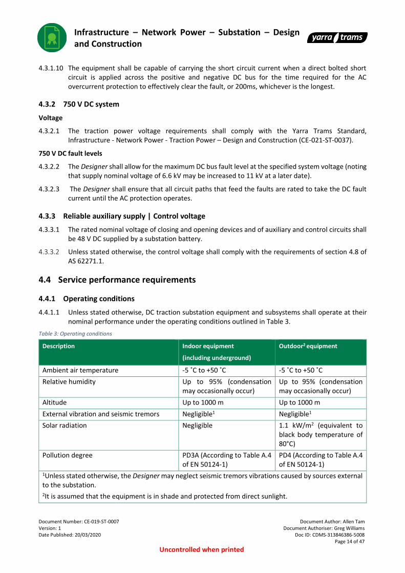
4.4.1.1 Unless stated otherwise, DC traction substation equipment and subsystems shall operate at their nominal performance under the operating conditions outlined in Table 3.
Table 3: Operating conditions
Description Indoor equipment
(including underground)
Outdoor2 equipment
Ambient air temperature -5 ˚C to +50 ˚C -5 ˚C to +50 ˚C
Relative humidity Up to 95% (condensation may occasionally occur)
Up to 95% (condensation may occasionally occur)
Altitude Up to 1000 m Up to 1000 m
External vibration and seismic tremors Negligible1 Negligible1
Solar radiation Negligible 1.1 kW/m2 (equivalent to black body temperature of 80°C)
Pollution degree PD3A (According to Table A.4 of EN 50124-1)
PD4 (According to Table A.4 of EN 50124-1)
1Unless stated otherwise, the Designer may neglect seismic tremors vibrations caused by sources external to the substation. 2It is assumed that the equipment is in shade and protected from direct sunlight.
Infrastructure – Network Power – Substation – Design and Construction
Document Number: CE-019-ST-0007 Document Author: Allen Tam Version: 1 Document Authoriser: Greg Williams Date Published: 20/03/2020 Doc ID: CDMS-313846386-5008
Page 15 of 47
Uncontrolled when printed
4.4.1.2 The Designer shall prevent condensation in situations where equipment performance may be compromised by its presence. Prevention methods may include, for example, special design of the building or housing, suitable ventilation and heating of the substation or use of dehumidifying equipment. External conduits and pits should be segregated form substation environments and should not allow excessive moisture to enter the substation environment.
4.4.2 Transport and storage conditions
4.4.2.1 Unless stated otherwise, DC traction substation equipment and subsystems shall be subject to the following transport and storage conditions:
• Minimum ambient temperature: -25 ˚C;
• Maximum ambient temperature: 55 ˚C; and
• Anticipated high levels of shock, vibration and inclination during transportation to site.
4.4.3 Noise
4.4.3.1 Unless stated otherwise, the Designer shall submit a Noise Report which provides evidence of compliance and includes at least the following:
• Design considerations and plan for compliance;
• Noise level measurements on site prior to construction works commencing; and
• Noise level measurements on site upon completion of commissioning of the electrical equipment.
Inside the DC traction substation
4.4.3.2 Noise levels inside the substation shall comply with all requirements of the Occupational Health
and Safety Act. In particular, the noise levels shall comply with the WorkSafe Victoria Compliance code: Noise.
4.4.3.3 In addition to the industry defined limits, Yarra Trams have defined a reduced noise exposure level: The noise exposure level inside a DC traction substation shall not exceed 75 dB(A) averaged over an eight-hour period.
Outside the DC traction substation
4.4.3.4 Noise levels outside the substation shall comply with all requirements of the Environment Protection Authority Victoria. In particular, the noise levels shall comply with the State Environment Protection Policy (Control of Noise from Commerce, Industry and Trade) No. N-1.
4.4.4 Electromagnetic compatibility (EMC)
4.4.4.1 Unless stated otherwise, the Designer shall submit an Electromagnetic Compatibility (EMC) Report which provides evidence of compliance and includes at least the following:
• Design considerations and plan for compliance;
• EMC measurements on site prior to construction works commencing; and
• EMC measurements on site upon completion of commissioning of the electrical equipment.
4.4.4.2 All equipment and subsystems within a DC traction substation and the DC traction substation itself shall comply with the following standards, in regard to electromagnetic field emissions and immunity:
• EN 50121-1;
• EN 50121-2; and

Infrastructure – Network Power – Substation – Design and Construction
Document Number: CE-019-ST-0007 Document Author: Allen Tam Version: 1 Document Authoriser: Greg Williams Date Published: 20/03/2020 Doc ID: CDMS-313846386-5008
Page 16 of 47
Uncontrolled when printed
• EN 50121-5.
4.4.4.3 All equipment and subsystems within a DC traction substation and the DC traction substation itself shall comply with the following standards, regarding exposure limits for electromagnetic fields:
• Victorian Traction Industry Electrical Safety Rules (The Orange Book);
• ICNIRP Guidelines: Guidelines for limiting exposure to time-varying electric and magnetic fields (1 Hz to 100 kHz); and
• ICNIRP Guidelines: Guidelines for limiting exposure to electric fields induced by movement of the human body in a static magnetic field and by time-varying magnetic fields below 1 Hz.
4.4.5 Special conditions
4.4.5.1 The Designer shall consider specific situations where a substation or its equipment are exposed to special service conditions. Situations may include, but are not limited to:
• A substation is to be installed near a main arterial road or factory and therefore may be subject to abnormal levels of pollutants and dust;
• A substation is to be installed in a very exposed area and therefore the substation building and/or outdoor equipment may be subject to significant adverse wind conditions;
• A substation is to be installed in an area where it may be affected by small animals or micro-organisms;
• A substation is to be installed close to the ocean and therefore may be subject to abnormal levels of salt in the air;
• A substation is installed in publicly accessible areas or without appropriate fencing; or
• A substation is installed in close proximity to road or tram traffic.
Information: In these specific situations, the Scope of Works shall specify any special design requirements for the substation.
4.5 Design requirements
4.5.1 General
4.5.1.1 The substation shall comply with AS 2067.
4.5.2 Insulation coordination
4.5.2.1 Insulation coordination shall comply with the general principles established in AS 2067 and EN 50124-1. The applicable insulation levels and clearances from these standards are provided in Table 4 and Table 5.

Infrastructure – Network Power – Substation – Design and Construction
Document Number: CE-019-ST-0007 Document Author: Allen Tam Version: 1 Document Authoriser: Greg Williams Date Published: 20/03/2020 Doc ID: CDMS-313846386-5008
Page 17 of 47
Uncontrolled when printed
Table 4: AC insulations levels and clearances
Nominal voltage,
Un
[r.m.s]
Highest
voltage,
Um
[kV r.m.s]
Rated short
duration
power
frequency
withstand
voltage, Ud
[kV r.m.s]
Rated
lightning
impulse
withstand
voltage, Up
[kV peak]
Minimum
phase-to-
earth
clearance
[mm]
Minimum
phase-to-
phase
clearance
[mm]
Non-
flashover
distance,
N
[mm]
Ground
safety
clearance
[mm]
230 V / 400 V AC
or;
240 V / 415 V AC
D D D D D D D
6.6 kV AC 7.2 20 60 90 105 100 2440
11 kV AC 12 28 95 160 185 175 2440
22 kV AC 24 50 150 280 325 310 2440
D: To be determined by the Designer.
Table 5: DC insulations levels and clearances
Nominal
voltage, Un
[kV]
Rated
voltage, UNe
[kV]
Rated
insulation
voltage, UNm
[kV]
OV Rated
impulse
voltage, UNi
[kV]
Power
frequency
withstand
voltage level,
Ua [kV]
Minimum
clearances in
air for the
standard
altitude
ranges1 [mm]
0.6 0.72 0.9 4 8 3.6 14
1This value is based on PD4 pollution degree.
4.5.2.2 The Designer is fully responsible for providing suitable insulations levels for the equipment and shall verify the values in Table 4 and Table 5.
4.5.2.3 The nominal voltage of 6.6 kV is included for completeness but is a non-preferred voltage for new installations. If the substation supply nominal voltage is 6.6 kV, the design of all HV AC equipment shall allow the substation supply nominal voltage to be increased to 11 kV at a later date. The applicable HV AC equipment includes, but is not limited to:
• HV AC switchgear and control;
• HV AC power cables;
• Metering equipment;
• Rectifier transformer; and
• Auxiliary transformer (if connected to HV AC).
4.5.2.4 Safety clearances for operational purposes and maintenance work shall be in accordance with Table 3.1 of AS 2067 and the Electrical Infrastructure Safety Rules (known as the Yellow Book) (IN-002-ST-0002).

Infrastructure – Network Power – Substation – Design and Construction
Document Number: CE-019-ST-0007 Document Author: Allen Tam Version: 1 Document Authoriser: Greg Williams Date Published: 20/03/2020 Doc ID: CDMS-313846386-5008
Page 18 of 47
Uncontrolled when printed
4.5.2.5 In accordance with clause 3.2 of AS 2067, the choice of the insulation levels should consider the method of neutral earthing in the system and the characteristics and locations of overvoltage limiting devices to be installed.
Information: If the Designer can prove to Yarra Trams that lower insulation levels can be achieved through appropriate choice of surge protection, the rated lightning impulse withstand voltage requirements in Table 4 may be relaxed.
4.5.3 Earthing and bonding
General
4.5.3.1 The earthing and bonding system shall comply with:
• AS 2067;
• All safety criteria within other standards and guidelines in accordance with clause 8.4.7.4 of AS 2067;
• ENA EG1 – Substation Earthing Guide;
• AS 3000; and
• EN 50123-7-1.
4.5.3.2 Unless stated otherwise, the Designer shall submit an Earthing Report which provides evidence of compliance and includes at least the following:
• Design considerations and plan for compliance;
• Soil resistivity test results;
• Field test results, validating the earthing grid; and
• All other items listed in clause 8.9 of AS 2067.
4.5.3.3 The complete earthing system design and construction is the responsibility of the Designer and shall provide safety (both within and outside the substation fence) to all personnel (including the public), as well as protection of all equipment from damage during fault conditions. In particular, the Designer shall apply the following principles:
• The Designer shall use the design procedure in accordance with clause 8.4 of AS 2067;
• In accordance with clause 8.4.4.6 of AS 2067, the responsibility of the Designer includes consideration of interactions with surrounding systems;
• In accordance with clause 8.4.6.3 (ii) of AS 2067, the earthing system shall be vandal resistant and have physical protection from activities that may be carried out in the vicinity;
• The earthing system construction shall include reference measurement points for future earth testing;
• The substation earthing system shall contain a buried earth grid beneath the building and switchyard;
• In accordance with clause B1.1 of AS 2067, the earthing system shall adopt the ‘combined earthing system’ principle.
• The earth grid system shall be designed for installation at a nominal depth of 500 mm below foundations level;
• The earth grid shall continue under and around the switchyard and be designed such that safe step, touch and transfer potentials are achieved;
• Sub-ground jointing shall be by cadwelding or brazing;
Infrastructure – Network Power – Substation – Design and Construction
Document Number: CE-019-ST-0007 Document Author: Allen Tam Version: 1 Document Authoriser: Greg Williams Date Published: 20/03/2020 Doc ID: CDMS-313846386-5008
Page 19 of 47
Uncontrolled when printed
• The design shall provide for the connection of a substation main earth bar to the outside earth grid. There shall be some means to visually and electrically confirm the connection of the substation main earth bar to the external earth grid. The disconnection point for testing shall be at the main earth bar. In accordance with clause B1.1 (f) of AS 2067, facilities should be provided to test earth electrodes without disconnection of the earthing system from the energized substation;
• The design shall provide for connection of earth grid to building reinforcing bars; and
• The Designer shall conduct all six field tests listed in clause 8.8 of AS 2067.
4.5.3.4 Unless stated otherwise, the Yarra Trams earthing system shall be separate from the Distribution Network Service Provider earthing system.
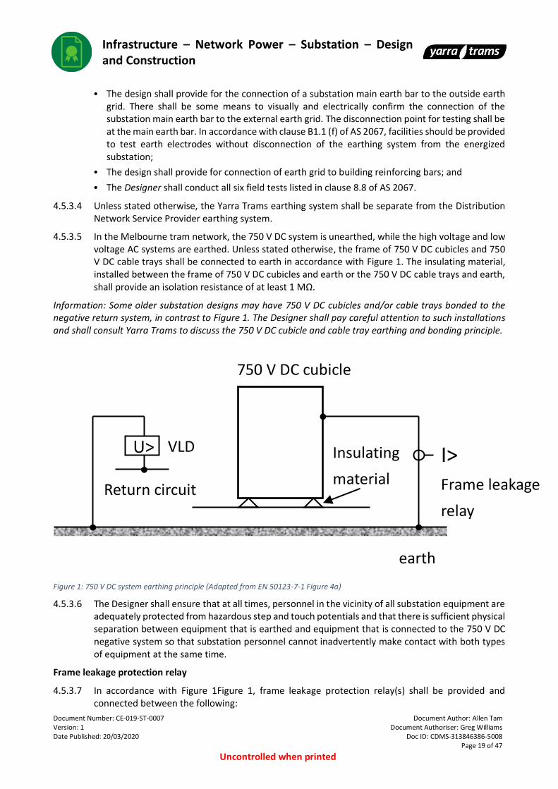
4.5.3.5 In the Melbourne tram network, the 750 V DC system is unearthed, while the high voltage and low voltage AC systems are earthed. Unless stated otherwise, the frame of 750 V DC cubicles and 750 V DC cable trays shall be connected to earth in accordance with Figure 1. The insulating material, installed between the frame of 750 V DC cubicles and earth or the 750 V DC cable trays and earth, shall provide an isolation resistance of at least 1 MΩ.
Information: Some older substation designs may have 750 V DC cubicles and/or cable trays bonded to the negative return system, in contrast to Figure 1. The Designer shall pay careful attention to such installations and shall consult Yarra Trams to discuss the 750 V DC cubicle and cable tray earthing and bonding principle.
Figure 1: 750 V DC system earthing principle (Adapted from EN 50123-7-1 Figure 4a)
4.5.3.6 The Designer shall ensure that at all times, personnel in the vicinity of all substation equipment are adequately protected from hazardous step and touch potentials and that there is sufficient physical separation between equipment that is earthed and equipment that is connected to the 750 V DC negative system so that substation personnel cannot inadvertently make contact with both types of equipment at the same time.
Frame leakage protection relay
4.5.3.7 In accordance with Figure 1Figure 1, frame leakage protection relay(s) shall be provided and connected between the following:
Insulating
material
I>
Frame leakage
relay
earth
Return circuit
U> VLD
750 V DC cubicle

Infrastructure – Network Power – Substation – Design and Construction
Document Number: CE-019-ST-0007 Document Author: Allen Tam Version: 1 Document Authoriser: Greg Williams Date Published: 20/03/2020 Doc ID: CDMS-313846386-5008
Page 20 of 47
Uncontrolled when printed
• The frame of 750 V DC cubicles and earth; and
• 750 V DC cable trays and earth.
Information: The number of relays to be provided and their respective location are defined in the Specifications and/or the Scope of Works.
4.5.3.8 If a breakdown occurs between the frame of any 750 V DC cubicle or 750 V DC cable tray and earth causing a current to flow, the frame leakage relay shall operate. In accordance with clause 6.5.7 of EN 50123-7-7, detection of a frame fault shall cause a mass trip of all in feeds to the 750 V DC cubicle or 750 V DC cable tray to isolate the fault.
Voltage limiting device
4.5.3.9 Voltage limiting device(s) shall be provided and connected between the main substation negative bus and the earth bus.
Information: The number of devices to be provided and their respective location are defined in the equipment specifications and/or the Scope of Works.
4.5.3.10 Requirements for the voltage limiting device(s) are given in the Voltage Limiting Device Specification (IN-021-ST-0011).
4.5.4 Protection
General requirements
4.5.4.1 Unless stated otherwise, the protection system shall comply with the requirements of the equipment specifications and the following standards:
• HV AC protection system: AS 2067 and AS 3851; and
• 750 V DC protection system: EN 50123-1, EN 50123-2, EN 50123-7-1.
4.5.4.2 At all times, the primary consideration for the protection system shall be to protect persons exposed to the traction power system (e.g. substation staff or members of the public). A secondary consideration is to protect electrical equipment and a final consideration is to minimise delays to operations.
4.5.4.3 Unless stated otherwise, in consultation with Yarra Trams, the Designer shall provide suitable protection settings for all protective devices in the substation except those devices related to the protection of the outgoing 750 V DC positive feeder cables (i.e. the normal scope shall include settings for incoming high voltage supply, low voltage auxiliary supply, battery charger, rectification system, 750 V DC rectifier and bus tie circuit breakers, 750 V DC positive bus, but excludes 750 V DC feeder circuit breakers and the associated protection relays). The protection settings shall not interfere with the design output capability of the substation.
4.5.4.4 The Designer shall be responsible for meeting the protection coordination requirements of the relevant Distribution Network Service Provider with respect to the incoming high voltage supply.
4.5.4.5 All protection wiring between equipment shall be hardwired.
4.5.4.6 Where an earthing design relies on fault clearing times and equipment maintenance requirements the designer shall clearly define the requirements for incorporation into operational and maintenance systems.
Information: The specific behaviour of the protection system will depend on the system configuration and other requirements defined in the specifications and Scope of Works. In particular, the specifications and/or Scope of Works shall nominate which equipment failure scenarios allow automatic restoration of power
Infrastructure – Network Power – Substation – Design and Construction
Document Number: CE-019-ST-0007 Document Author: Allen Tam Version: 1 Document Authoriser: Greg Williams Date Published: 20/03/2020 Doc ID: CDMS-313846386-5008
Page 21 of 47
Uncontrolled when printed
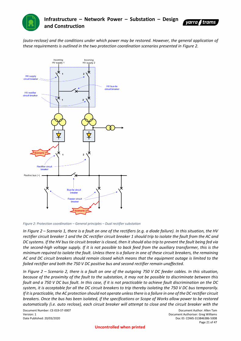
(auto-reclose) and the conditions under which power may be restored. However, the general application of these requirements is outlined in the two protection coordination scenarios presented in Figure 2.
Figure 2: Protection coordination – General principles – Dual rectifier substation
In Figure 2 – Scenario 1, there is a fault on one of the rectifiers (e.g. a diode failure). In this situation, the HV rectifier circuit breaker 1 and the DC rectifier circuit breaker 1 should trip to isolate the fault from the AC and DC systems. If the HV bus tie circuit breaker is closed, then it should also trip to prevent the fault being fed via the second-high voltage supply. If it is not possible to back feed from the auxiliary transformer, this is the minimum required to isolate the fault. Unless there is a failure in one of these circuit breakers, the remaining AC and DC circuit breakers should remain closed which means that the equipment outage is limited to the failed rectifier and both the 750 V DC positive bus and second rectifier remain unaffected.
In Figure 2 – Scenario 2, there is a fault on one of the outgoing 750 V DC feeder cables. In this situation, because of the proximity of the fault to the substation, it may not be possible to discriminate between this fault and a 750 V DC bus fault. In this case, if it is not practicable to achieve fault discrimination on the DC system, it is acceptable for all the DC circuit breakers to trip thereby isolating the 750 V DC bus temporarily. If it is practicable, the AC protection should not operate unless there is a failure in one of the DC rectifier circuit breakers. Once the bus has been isolated, if the specifications or Scope of Works allow power to be restored automatically (i.e. auto reclose), each circuit breaker will attempt to close and the circuit breaker with the

Infrastructure – Network Power – Substation – Design and Construction
Document Number: CE-019-ST-0007 Document Author: Allen Tam Version: 1 Document Authoriser: Greg Williams Date Published: 20/03/2020 Doc ID: CDMS-313846386-5008
Page 22 of 47
Uncontrolled when printed
faulty cable will fail to close. This behaviour interrupts tram operations momentarily, and then limits the equipment taken out of service to the faulty DC feeder cable so that the remainder of the system can continue operating normally.
Lightning and surge protection
4.5.4.7 Unless stated otherwise, the lightning and surge protection system shall comply with the equipment specifications, the requirements of Table 4 and the following standards:
• AC surge protection system: AS 2067, AS 1768 (lightning protection for buildings), AS 1307.2 (AC surge protection devices); and
• 750 V DC surge protection system: EN 50124-1, EN 50124-2, EN 50526-1.
4.5.4.8 Lightning and surge protection shall be provided for all equipment that is exposed to the risk of lightning or surges (but multiple items of equipment might be protected by one device as part of a zoned system). The need for protection against lightning surges is essential unless the location provides an inherent zone of protection from lightning surges.
4.5.4.9 Lightning and surge protection systems shall present a low risk to workers in the event of a nearby or distant lightning strike. As a result, the safety of personnel working on or near the surge protective equipment shall be considered when designing the layout of the surge protective equipment or the route for earth conductors.
4.5.4.10 Surge protected wiring shall be segregated from non-surge protected wiring to prevent coupling of surges between the wiring. Earth wires are to be considered as non-surge protected wiring. The amount of segregation shall be suitable for the expected level of surge on the non-protected wiring.
4.5.4.11 When considering lightning and surge protection, the equipment selection principles shall be as follows:
• shall be fit for purpose;
• shall match the insulation coordination requirements and the detailed equipment specifications for all equipment supplying the surge zone; and
• surges shall be kept within the tolerances of the equipment being protected.
4.5.4.12 All entry points for surges shall be considered. Lightning and/or surges occur, enter, or are induced into the system through one or several of the following:
• HV AC system;
• LV AC system;
• 750 V DC system;
• DC negative system;
• Communication lines;
• Earth grid; and
• Electrolysis system.
4.5.5 Interlocking
4.5.5.1 For the purpose of this standard and the substation equipment specifications, interlocking shall be defined as an electrical, electronic or mechanical device or system which prevents an element from changing state due to the state(s) of another element(s), and vice versa. Figure 3 provides an example of the interlocking principles for an earth switch in withdrawable HV AC switchgear. The following definitions shall apply:

Infrastructure – Network Power – Substation – Design and Construction
Document Number: CE-019-ST-0007 Document Author: Allen Tam Version: 1 Document Authoriser: Greg Williams Date Published: 20/03/2020 Doc ID: CDMS-313846386-5008
Page 23 of 47
Uncontrolled when printed
• Mechanical interlocking: A device or system which prevents a change in state by blocking motion. E.g. trapped key systems. E.g. a mechanical lever preventing the closing of an earth switch while a circuit breaker is racked in.
• Electrical interlocking: A device or system which prevents a change in state using logic in a wired circuit. E.g. a relay logic circuit which prevents the closing of a circuit breaker.
• Electronic interlocking: A device or system which prevents a change in state using logic in software. E.g. electronic interlocking using the software in a PLC or protection relay.
Figure 3: Interlocking – General principles and worked example– High voltage earth switch
Information: Whenever practical, preference should be given to mechanical interlocks.
4.5.5.2 In the event of the loss of auxiliary power, the interlocking should be designed to be fail-safe.
4.5.5.3 All interlocking wiring, if applicable, between equipment shall be hardwired.
4.5.5.4 In general, enclosure access interlocking is not required where:
• The enclosure does not have doors and instead only has panels which can only be removed using a tool.
• The enclosure is within secured operational areas.
• The enclosure and particularly the removeable panels, have suitable warning signage.
4.5.6 Control panels
4.5.6.1 Local electrical control and/or indication for each item of equipment shall be from control panels, which are situated on the equipment they control or indicate, unless stated otherwise. Terminology used to describe control operation points shall be consistent with Yarra Trams electrical sectioning diagrams.
4.5.6.2 Additionally, a single central substation control and indication panel shall be provided and located in a safe zone within the substation. Requirements for the central substation control and indication panel are given in the SCADA Cubicle and VicTrack Communications Cubicle Specification (IN-021-ST-0007).
4.5.7 Equipment interfaces | SCADA
4.5.7.1 All equipment shall be able to be electrically controlled and/or indicated locally and remotely through the SCADA system.
S0 HVCB = Racked in
ES = Open
S1 HVCB = Racked out
ES = Open
S2 HVCB = Racked out
ES = Closed
HVCB = Racked in
ES = Closed S3
Infrastructure – Network Power – Substation – Design and Construction
Document Number: CE-019-ST-0007 Document Author: Allen Tam Version: 1 Document Authoriser: Greg Williams Date Published: 20/03/2020 Doc ID: CDMS-313846386-5008
Page 24 of 47
Uncontrolled when printed
4.5.7.2 The equipment SCADA indication shall be provided by means of dedicated and electrically isolated normally open and normally closed auxiliary contacts of switchgear, and on and off contact of indication relays.
4.5.7.3 The SCADA control will be provided from a Remote Terminal Unit (RTU) located in the SCADA cubicle.
4.5.7.4 The minimum equipment SCADA control and indication requirements are outlined in each equipment specification. Figure 4 outlines how to interpret these requirements in each specification and applicable definitions.
Figure 4: Interpretation of equipment specification SCADA points table
4.5.7.5 The substation shall not be a fully digital substation according to IEC 61850. The substation shall adhere to Yarra Trams’ current philosophy which includes a combination of hardwired and digital connections between equipment, according to the following principles:
• Hardwired connections use: Protection functionality between equipment, interlocking functionality between equipment, ‘critical’ SCADA indication and all equipment SCADA control; and
• Digital connections use: ‘Non-critical’ SCADA indication.
4.5.7.6 For digital SCADA points, the following communication protocols are supported by Yarra Trams and are listed in order of preference:
• DNP3.0 TCP/IP;
• Modbus TCP/IP; and
• Modbus Serial (only applicable for legacy systems).
4.5.7.7 As outlined in section 4.8 of this document, the Designer shall submit the following documentation to Yarra Trams to facilitate the SCADA integration and commissioning:
• SCADA and communications system overview drawing: This drawing would include details such as, but not limited to, all network connected devices and the network topology.
• SCADA equipment interconnection design and drawings:
TBC

Infrastructure – Network Power – Substation – Design and Construction
Document Number: CE-019-ST-0007 Document Author: Allen Tam Version: 1 Document Authoriser: Greg Williams Date Published: 20/03/2020 Doc ID: CDMS-313846386-5008
Page 25 of 47
Uncontrolled when printed
• SCADA points description excel sheet: Yarra Trams shall provide an excel template to the Designer which describes the ‘Standard’ SCADA configuration.
4.5.8 Labelling and identification
4.5.8.1 Unless stated otherwise, the substation labelling, identification and marking shall comply with AS 2067 and AS 1319.
4.5.8.2 Cubicle identification and terminal markings shall be in accordance with IEC 60445.
4.5.8.3 Signage, warning signs (for example warning notices) or safety instruction notices shall be displayed where there is a potentially ambiguous or dangerous situation.
4.5.8.4 In accordance with clause 6.9.1 of AS 2067, where an item of equipment consists of two or more units with access to the rear, such labelling shall also be located on a fixed portion at the rear of each unit.
4.5.8.5 Nameplates shall be provided for each item of equipment as specified in the relevant specifications and shall be durable, visible and legible.
4.5.8.6 The colors on insulation shall be continuous for the entire length of the conductors. The color on bare busbars shall be clearly visible without giving the impression that it is a form of insulation.
4.5.8.7 A system of permanent numbering for identification of cables shall be used. The numbers shall be allotted in a logical manner so that parts of the circuit can be readily identified and the purpose and destination of any wire can be determined from the wiring diagram. The wire number shall appear on both ends of each wire. The numbers shall be securely attached to the cables and be easily readable. The numbers shall be adjacent to the cable termination and shall read from left to right. Labelling shall only be removable after the wire has been released from its termination.
4.5.9 Efficiency
4.5.9.1 In accordance with APPENDIX D – ECO-FRIENDLY DESIGN, the Designer shall consider the substation energy efficiency. The energy efficiency is defined as the ratio of the 750 V DC output power to the HV AC input power. The target substation energy efficiency, as a function of the DC output current of the substation rectifier(s), is given in Table 6.
Table 6: Target substation energy efficiency
DC output current of the substation
rectifier(s) [A]
Target substation efficiency, during
traction Mode
Target substation efficiency, during
recovery mode (e.g. if inverters are
installed)
0.5 × In > 0.95 > 0.95
In > 0.95 > 0.95
1.5 × In > 0.95 > 0.95
In: Rated DC output current of the substation rectifier(s).
4.5.10 Building and equipment layout
4.5.10.1 The layout of electrical equipment shall consider:
• The equipment that is to be mounted or located within the substation building;
• Specific details of each equipment item (i.e. rating, physical dimensions, weight, exact location of incoming/outgoing cables);

Infrastructure – Network Power – Substation – Design and Construction
Document Number: CE-019-ST-0007 Document Author: Allen Tam Version: 1 Document Authoriser: Greg Williams Date Published: 20/03/2020 Doc ID: CDMS-313846386-5008
Page 26 of 47
Uncontrolled when printed
• Grouping arrangement of equipment (i.e. similar or related items should be grouped together and ordered in a logical sequence from input to output with a minimum number of crossovers);
• Sufficient clearances from equipment to building walls, fences and other equipment for installation, maintenance, inspection and removal requirements;
• Maintenance of consumable equipment and fittings should avoid the use of ladders or lifting devices; and
• Operation of all switchgear from ground level without the need to work off platforms.
Information: Yarra Trams are in the process of developing a standard DC traction substation design equipment layout, which will be made available on PTV DMS.
4.5.10.2 Requirements for the building and equipment layout are given in the Building Specification (IN-021-ST-0006).
4.6 Construction requirements
4.6.1 Quality and workmanship
4.6.1.1 All materials, equipment and systems shall be new.
4.6.2 Noise
4.6.2.1 The Designer shall comply with all requirements of the Environment Protection Authority Victoria.
4.6.3 Residents
4.6.3.1 The Designer shall notify residents of all work to occur during construction and potential impacts including, but not limited to:
• Noise level during construction;
• Impact on traffic flow;
• Safety of commuters;
• Councils in the case of council trees or trees under environmental protection schemes; and
• Impact on any bushes/trees in the vicinity.
4.6.4 Inspection of works
4.6.4.1 Prior to commencement of any site works, a site inspection involving the Designer and Yarra Trams shall be held to gain familiarisation with the tramway environment, principles of the design and site-specific considerations.
4.6.4.2 The Designer is responsible for the totality of all works on site.
4.6.4.3 During the performance of works, inspections shall be carried out by Yarra Trams to ensure compliance with this standard and equipment specifications. Additional random safety inspections shall also be carried out by Yarra Trams at its discretion.
4.6.4.4 General inspections will be carried out by Yarra Trams prior to and after commissioning. Yarra Trams shall also attend the commissioning. The Designer shall comply with hold points and shall ensure reasonable notification for Yarra Trams representatives to attend.
4.6.4.5 The Designer shall maintain, on an ongoing basis, a set of marked up construction drawings on site. Yarra Trams shall have access to these drawings to monitor the progress of the construction. Particularly at brownfield sites, the construction drawings shall be adequate to enable emergency
Infrastructure – Network Power – Substation – Design and Construction
Document Number: CE-019-ST-0007 Document Author: Allen Tam Version: 1 Document Authoriser: Greg Williams Date Published: 20/03/2020 Doc ID: CDMS-313846386-5008
Page 27 of 47
Uncontrolled when printed
operation and reactive maintenance of any in service equipment while the construction is occurring. Construction plans are to be maintained on site and kept up to date on progress.
4.6.5 Site earth works
4.6.5.1 The Designer has a duty of care to observe underground networks when digging or excavating. Suitable measures shall be taken to safeguard the existing underground services.
4.6.5.2 Underground network information should be sought well in advance to construction activities. The Designer shall inform itself of the locations of underground services through the “Dial Before You Dig Service”. In addition to the information provided by the “Dial Before You Dig Service” and the earthing layout provided as part of the detailed design, the Designer shall also carry out a visual check of the area around the site to see whether any cables or services are entering the site.
4.6.5.3 If there are any underground services, the Designer shall inform Yarra Trams as well the appropriate authority prior to carrying out any excavations. All requirements of the authority that owns the underground service must be followed when carrying out work.
4.6.6 The earth grid
4.6.6.1 The earth grid shall be installed and tested and the earthing report, in accordance with clause 4.5.3.2, shall be approved by Yarra Trams before the concrete base is laid.
4.6.6.2 Further construction work shall not proceed until Yarra Trams evaluates the earth grid test results, reviews the earthing report and confirms that the results are satisfactory.
4.6.7 Testing and commissioning
4.6.7.1 The Designer shall supply all testing schedules for approval by Yarra Trams. Testing shall take place using the approved test schedules as appropriate.
4.6.7.2 When appropriate, the Designer shall inform Yarra Trams that the substation is ready for connection to the DNSP’s network.
Information: Yarra Trams shall assist the Designer to make arrangements with the DNSP to inspect the substation and to issue a HV clearance certificate, after which the supply will be connected and the substation will become energised.
4.6.8 Training
4.6.8.1 The Designer shall train allocated Yarra Trams representatives in all aspects of the new electrical installation. All operational, technical, safety and environmental aspects of the new installation shall be covered during the training. The technical training shall involve going through the as constructed drawings, operator instructions and a site visit.
4.6.8.2 The Designer shall run two training sessions on different days (per substation), to accommodate the availability of Yarra Trams representatives.
4.6.8.3 Training shall be completed before the substation is placed into service.
4.6.8.4 Where ever possible the equipment operation will be aligned to existing operating systems within Yarra Trams.

Infrastructure – Network Power – Substation – Design and Construction
Document Number: CE-019-ST-0007 Document Author: Allen Tam Version: 1 Document Authoriser: Greg Williams Date Published: 20/03/2020 Doc ID: CDMS-313846386-5008
Page 28 of 47
Uncontrolled when printed
4.7 Reliability, Availability, Maintainability and Safety (RAMS) requirements
4.7.1 General
4.7.1.1 The Designer shall comply with the Yarra Trams Engineering Management System.
4.7.1.2 The substation, as a whole, shall comply with the general requirements in Table 7.
Table 7: RAMS – General requirements
Description Requirement
Operational availability1, Ao ≥ 0.99
Design life2 ≥ 30 years 1Operational availability is the probability that an item will operate satisfactorily at a given point in time when used in an actual or realistic operating and support environment. It includes, but is not limited to:
• Undetected fault down time;
• Administrative down time;
• Logistics down time;
• Preventive maintenance down time; and
• Corrective maintenance down time. Operational availability is a measure which extends the definition of availability to elements controlled by project managers, manufacturers and logistics companies. Elements may include the quantity and proximity of spares, tools and maintenance staff availability. In accordance with EN 61703, operational availability shall be defined by the expression:
Ao = MUT / (MUT + MDT) 2The design life of electronic devices shall be ≥ 15 years.
Information: Definition and detailed guidance on mathematical treatment of RAMS terms is given in EN 61703.
4.7.1.3 Unless stated otherwise, the Designer shall submit a RAMS Report which provides evidence of compliance. The report shall at least include the following:
• Consideration of how the operating conditions outlined in section 4.4.1 affect the RAMS of the substation;
• Details of the maintenance regimes required to achieve the reliability requirements stated; and
• Consideration of how electronic devices will be replaced at the end of their design life (e.g. 15 years) to ensure the design life of the substation (e.g. 30 years).
4.7.1.4 The following substation specific definitions shall apply:
• For a dual rectifier substation, the substation is only considered to be in down time when both rectifiers are at fault;
• The design shall nominate and ensure maximum reliability for redundant systems;
• The design phase shall consider the following reliability objectives:
o MTBF higher than 12,000 hours for the substation.
o MTBF higher than 50,000 hours for each cubicle/panel.
4.7.1.5 The types of maintenance to support the substation are:
• Preventive maintenance; and
• Corrective maintenance.

Infrastructure – Network Power – Substation – Design and Construction
Document Number: CE-019-ST-0007 Document Author: Allen Tam Version: 1 Document Authoriser: Greg Williams Date Published: 20/03/2020 Doc ID: CDMS-313846386-5008
Page 29 of 47
Uncontrolled when printed
4.7.1.6 Preventive maintenance tasks shall be detailed in the Technical Maintenance Plan of the substation.
4.7.1.7 The Designer shall request information from Yarra Trams as necessary to calculate the substation operational availability. Information requests may include:
• MTR values for equipment;
• MAD values for maintenance; or
• Maintenance staff availability;
Information: A Line-Replaceable Unit (LRU) is a part of a system that is designed to be replaced quickly at an operating location (e.g. a diode or a snubber in a rectifier cubicle). The Yarra Trams LRU MTR values are ‘30 minutes for an LRU whose weight is lower than 20 kg’ and ‘4 hours for an LRU whose weight is higher than 20 kg’.
4.7.2 Tools, fault diagnostic equipment and spare parts
4.7.2.1 The Designer shall provide a recommended list of tools, fault diagnostic equipment and spare parts, which the Designer considers will be required to install and maintain the substation and its equipment.
4.7.2.2 The Designer should use standard products (or products accepting standard stock lines) to allow for minimum spare parts to be carried into stock. Where superior performing products or equipment are available, they shall be referred to Yarra Trams for prior approval.
4.8 Documentation requirements
4.8.1 General
4.8.1.1 Unless stated otherwise, submitted documentation for the DC traction substation shall at least comprise the items outlined in Table 8. This documentation shall be provided for the substation throughout the procedure outlined in the Manage Design Procedure (CE-021-PR-0006). Additional documentation requirements are defined in each equipment specification.
Table 8: Documentation
Documentation
Syst
em
s
des
ign
Pre
limin
ary
des
ign
Det
aile
d d
esig
n
Co
mm
issi
on
ing
(pri
or
to
ener
gisa
tio
n)
Pro
ject
co
mp
leti
on
Statement of compliance
Substation single-line diagram 1
Substation equipment layout and schedule layout
1
The detailed configuration of electrical equipment to be installed (e.g. number of rectifiers, transformers, circuit breakers, feeder panels, battery charger, etc)
1

Infrastructure – Network Power – Substation – Design and Construction
Document Number: CE-019-ST-0007 Document Author: Allen Tam Version: 1 Document Authoriser: Greg Williams Date Published: 20/03/2020 Doc ID: CDMS-313846386-5008
Page 30 of 47
Uncontrolled when printed
Documentation
Syst
em
s
des
ign
Pre
limin
ary
des
ign
Det
aile
d d
esig
n
Co
mm
issi
on
ing
(pri
or
to
ener
gisa
tio
n)
Pro
ject
co
mp
leti
on
Electrolysis mitigation requirements 1
Substation integration design
Full details of equipment selection and bill of materials
1
Main and auxiliary circuit diagrams 1
Equipment interconnection design and drawings
1
SCADA and communications system overview drawing
1
SCADA equipment interconnection design and drawings
1
SCADA points description excel sheet 1
Equipment earthing and bonding connections, design and drawings
1
Negative, earthing and electrolysis busbars design and drawings
1
Protection and control system design and drawings
1
Interlocking system design and drawings
Cable and wiring schedules
Design reports
General report (including Equipment rating calculations, technical specifications for the substation and each individual item of equipment)
Protection report (including fault calculations, protection coordination)
Noise report (see clause 4.4.3.1)
EMC report (see clause 4.4.4.1)
Earthing report (see clause 4.5.3.2)
RAMS report (see clause 4.7.1.3)
Testing and commissioning

Infrastructure – Network Power – Substation – Design and Construction
Document Number: CE-019-ST-0007 Document Author: Allen Tam Version: 1 Document Authoriser: Greg Williams Date Published: 20/03/2020 Doc ID: CDMS-313846386-5008
Page 31 of 47
Uncontrolled when printed
Documentation
Syst
em
s
des
ign
Pre
limin
ary
des
ign
Det
aile
d d
esig
n
Co
mm
issi
on
ing
(pri
or
to
ener
gisa
tio
n)
Pro
ject
co
mp
leti
on
Test and commissioning plans 2
Application for approval to place electrical installation into service
Certificate of electrical safety
Installation, operation and maintenance manual(s)
2
Operation manual(s) 2
Maintenance manual(s) 2
Technical maintenance plan 2
Calibration certificates (type test certificates, NATA certification of metering equipment, factory and commissioning test overcurrent calibration charts for the full range of all settings for each DC circuit breaker supplied);
4.8.1.2 The Designer shall be solely responsible for the creation, supply and certification of all new drawings and modifications to existing drawings where necessary.
4.8.1.3 All drawings shall be technically and functionally correct, accurately reflecting the installed equipment and associated circuits.
4.8.1.4 Documentation of the design of equipment, assemblies or installations shall be supplied to Yarra Trams at each design step for review and approval, as part of the gate process. The main purpose of the review and approval gate processes is to determine that the design is compliant with the technical standards and specifications.
Installation, operation and maintenance manuals:
4.8.1.5 The Designer shall provide installation, operation and maintenance manuals for all substation equipment. The manuals shall at least include a description of all the servicing activities, the overhaul instructions, adjustments procedures, changing components for repairs, fault finding procedures, any software programs (where a PLC/IED is utilized), a complete set of as-built drawings and a comprehensible spare parts list for the electrical equipment.
Technical maintenance plan:
4.8.1.6 The Designer shall be solely responsible for the creation, supply and certification of the technical maintenance plan for a new substation and the modifications to existing substation technical maintenance plans where necessary (e.g. replacing a single piece of equipment in a substation). The technical maintenance plan shall at least include:
• A summarised maintenance policy for the equipment;

Infrastructure – Network Power – Substation – Design and Construction
Document Number: CE-019-ST-0007 Document Author: Allen Tam Version: 1 Document Authoriser: Greg Williams Date Published: 20/03/2020 Doc ID: CDMS-313846386-5008
Page 32 of 47
Uncontrolled when printed
• Summarised preventive maintenance schedules for the equipment; and
• Summarised corrective maintenance instructions for the most commonly replaced parts of the supplied equipment.
Information: The technical maintenance plan is a useful summary document of relevant parts of the equipment installation, operation and maintenance manuals for all equipment supplied.
As-built documentation:
4.8.1.7 Once the substation has been built and commissioned, it is the responsibility of the Designer to produce as-built documentation, which includes mark-ups and any minor design changes due to unforeseen site constraints. Mark-ups and/or minor design changes shall be approved by Yarra Trams.
4.8.2 Documentation requirements and formatting
4.8.2.1 As-built drawings shall be fully compliant with the PTV Infrastructure Drafting Standards.
4.8.2.2 As-built documentation shall be uploaded into the PTV DMS and PASS Asset Information System in accordance with Drawing Management System Standard Processes (PTV-NTS-012).
4.8.2.3 Reports and other non-CAD documentation shall be submitted in .pdf and .docx formats.
4.8.2.4 All documentation shall be provided in English.
4.8.2.5 Technical drawings shall comply with AS 1100 series.

Infrastructure – Network Power – Substation – Design and Construction
Document Number: CE-019-ST-0007 Document Author: Allen Tam Version: 1 Document Authoriser: Greg Williams Date Published: 20/03/2020 Doc ID: CDMS-313846386-5008
Page 33 of 47
Uncontrolled when printed
5 DIAGRAMS AND GUIDANCE
5.1 Single line diagram of a DC traction substation
Figure 5: Typical single line diagram of the DC traction substation – Single rectifier substation (LV auxiliary supply option 1)

Infrastructure – Network Power – Substation – Design and Construction
Document Number: CE-019-ST-0007 Document Author: Allen Tam Version: 1 Document Authoriser: Greg Williams Date Published: 20/03/2020 Doc ID: CDMS-313846386-5008
Page 34 of 47
Uncontrolled when printed
6 RELATED LEGISLATION & DOCUMENTS
6.1.1.1 The design and construction of DC traction substations shall be consistent with the best engineering practices and shall comply with all of the referenced documents listed in this section. These referenced documents shall be read in conjunction with this standard.
6.1.1.2 Unless stated otherwise, all referenced documents shall refer to the most recent published versions of them at the time of invitation to tender.
6.1.1.3 Where no equipment specification exists, the general principles outlined in this document shall be applied along with the requirements of the relevant Australian Standards, International Standards, Industry codes of practice, guidelines, policies and rules as well as government regulations and other legislative documents.
6.1.1.4 Wherever a conflict exists in the requirements of these documents, the hierarchy of technical standards shall be observed, in accordance with Governance of Technical Standards Guideline (CE-021-GL-0003).
Table 9: Referenced documents
Name Document number
Acts
Environment Protection Act
Rail Safety Act (Local Operations) Act 2006 (Vic)
Rail Safety National Law Application Act 2013 No 22
Historic Building Act
Occupational Health and Safety Act
Building Act
Regulations & other legislative documents
Environment Protection (Industrial Waste Resource) Regulations 2009
Rail Safety (Local Operations) (Accreditation and Safety) Regulations
Building Regulations
Electricity Safety (Installations) Regulations
Electricity Safety (Cathodic Protection) Regulations
Industry codes of practice, guidelines, policies and rules
Victorian Traction Industry Electrical Safety Rules (known as the Orange Book)
Building Code of Australia
Victorian Electricity Distributors Service & Installation Rules
ROA Code “For the installation of other party’s services and Pipelines within Railway Boundaries”
Electricity Distribution Code – Essential Services Commission – Victoria
ENA EG1 – Substation Earthing Guide
WorkSafe Victoria Compliance code: Noise
State Environment Protection Policy (Control of Noise from Commerce, Industry and Trade) No. N-1

Infrastructure – Network Power – Substation – Design and Construction
Document Number: CE-019-ST-0007 Document Author: Allen Tam Version: 1 Document Authoriser: Greg Williams Date Published: 20/03/2020 Doc ID: CDMS-313846386-5008
Page 35 of 47
Uncontrolled when printed
Name Document number
Public Transport of Victoria
Drawing Management System Standard Processes PTV-NTS-012
PTV Infrastructure Drafting Standards
Bonding standard – Connection details Drawing STD_T3000
Bonding standard – Asset bonding layouts Drawing STD_T3001
Yarra Trams
Engineering Change Management Procedure CE-021-PR-0020
Manage Design Procedure CE-021-PR-0006
Deviation from Standards Procedure CE-021-PR-0004
Safety in Design SS-021-PR-0001
Project Risk Management PR-016-PR-0001
Electrical Infrastructure Safety Rules (known as the Yellow Book) IN-002-ST-0002
Governance of Technical Standards Guideline CE-021-GL-0003
Infrastructure - Network Power - Traction Power – Design and Construction CE-021-ST-0037
Rectifier Transformer Specification IN-021-ST-0002
Rectifier Converter Specification Not Available
Cable Specification IN-021-ST-0003
Negative Cubicle Specification IN-021-ST-0013
750 V DC Switchgear and Control Specification Not Available
750 V DC External Isolator Specification IN-021-ST-0004
750 V DC Transducer and Measurement Device Specification IN-021-ST-0014
HV AC Switchgear and Control Specification IN-021-ST-0012
Voltage Limiting Device Specification IN-021-ST-0011
Auxiliary Transformer Specification Not Available
LV Switchboards Specification IN-021-ST-0009
Battery and Battery Charger Specification IN-021-ST-0010
Electrolysis Mitigation Cubicle Specification IN-021-ST-0005
Building Specification IN-021-ST-0006
Outdoor Cable Pit Specification Not Available
SCADA Cubicle and VicTrack Communications Cubicle Specification IN-021-ST-0007
Australian Standards
Surge arresters – Metal-oxide surge arresters without gaps for a.c. systems AS 1307.2
Safety signs for the occupational environment AS 1319
Lightning protection AS/NZS 1768
Substations and high voltage installations exceeding 1 kV a.c. AS 2067
Electrical installations (known as the Australian/New Zealand Wiring Rules) AS 3000
The calculation of short-circuit currents in three-phase a.c. systems AS 3851
Guide for the selection of insulators in respect of polluted conditions AS 4436

Infrastructure – Network Power – Substation – Design and Construction
Document Number: CE-019-ST-0007 Document Author: Allen Tam Version: 1 Document Authoriser: Greg Williams Date Published: 20/03/2020 Doc ID: CDMS-313846386-5008
Page 36 of 47
Uncontrolled when printed
Name Document number
Electromagnetic compatibility (EMC) AS/NZS 61000 series
High-voltage switchgear and control gear – Common specifications AS 62271.1
International Standards
ICNIRP Guidelines: Guidelines for limiting exposure to time-varying electric and magnetic fields (1 Hz to 100 kHz)
ICNIRP Guidelines: Guidelines for limiting exposure to electric fields induced by movement of the human body in a static magnetic field and by time-varying magnetic fields below 1 Hz
Railway applications – Electromagnetic compatibility – Part 1: General EN 50121-1
Railway applications – Electromagnetic compatibility – Part 2: Emission of the whole railway system to the outside world
EN 50121-2
Railway applications – Electromagnetic compatibility – Part 5: Emission and immunity of fixed power supply installations and apparatus
EN 50121-5
Railway applications – Fixed installations – D.C. switchgear EN 50123 series
Railway applications – Insulation coordination – Part 1: Basic requirements – Clearances and creepage distances for all electrical and electronic equipment
EN 50124-1
Railway applications – Insulation coordination – Part 2: Over voltages and related protection
EN 50124-2
Railway applications. Supply voltages of traction systems EN 50163
Mathematical expressions for reliability, availability, maintainability and maintenance support terms
EN 61703
Basic and Safety Principles for Man-Machine Interface, Marking and Identification – Identification of Equipment Terminals, Conductor Terminations and Conductors
IEC 60445
DOCUMENT VERSION CONTROL Table 10: Document version control
Version History Date Detail
1.0 20 Mar 2020 Original approved issue

Infrastructure – Network Power – Substation – Design and Construction
Document Number: CE-019-ST-0007 Document Author: Allen Tam Version: 1 Document Authoriser: Greg Williams Date Published: 20/03/2020 Doc ID: CDMS-313846386-5008
Page 37 of 47
Uncontrolled when printed
APPENDIX A – GLOSSARY Table 11: Glossary - Words
Word Definition
Application for approval to place electrical installation into service
Internal Yarra Trams document to be submitted prior to energisation.
Contact wire Overhead cable used to transmit electrical energy from the substations to the trams and in direct contact with the pantograph of each tram.
Control voltage See “Reliable auxiliary supply”. The terms “Control voltage” and “Reliable auxiliary supply” are used interchangeably.
Corrective maintenance Maintenance carried out after fault detection to effect restoration.
Demand “Demand” means the active power or apparent power consumed at point of common coupling integrated over fifteen or thirty minute period.
Designer The party who is fully responsible for the suitability and compliance of the design of the DC traction substation and all its equipment and subsystems.
Design life The period of time during which the item/system is designed to work within its parameters. It is the length of time between placement into service and disposal of the item/system.
Feeder Panel The term “Panel” or “Feeder Panel” means any enclosed assembly comprising a DC feeder circuit breaker, together with any associated protection and control equipment for the purpose of operating trams.
Life cycle Series of identifiable stages through which an item or system goes, from its conception to disposal.
Panel See “Feeder Panel”.
Preventive maintenance Maintenance carried out to mitigate degradation and reduce the probability of failure.
Reliable auxiliary supply Supply voltage of closing and opening devices and of auxiliary and control circuits.
Scope of Works The Scope of Works is a key document that defines the specific project-related requirements such as the configuration and rating of equipment to be installed. It prevails over all the specifications.
Specifications Set of documents that define the general requirements applicable to each item of equipment or subsystem to be installed within a DC traction substation.
Substation An electrical installation equipped to transform and rectify HV AC supplies before distributing it through 750 V DC circuit breakers to the overhead system.
Tie station An electrical installation not equipped to transform and rectify HV AC supplies but equipped with 750 V DC circuit breakers to distribute traction power through the overhead system.
Trolley wire See “Contact wire”.
Table 12: Glossary - Abbreviations
Abbreviation Definition
AC Alternating Current

Infrastructure – Network Power – Substation – Design and Construction
Document Number: CE-019-ST-0007 Document Author: Allen Tam Version: 1 Document Authoriser: Greg Williams Date Published: 20/03/2020 Doc ID: CDMS-313846386-5008
Page 38 of 47
Uncontrolled when printed
Abbreviation Definition
DC Direct Current
DNSP Distribution Network Service Provider
ECM Engineering Change Management (internal Yarra Trams abbreviation)
EMC Electromagnetic Compatibility
EMS Engineering Management System (internal Yarra Trams abbreviation)
EPD Environmental Product Declaration
ES Earth Switch
HV “High Voltage” means a nominal voltage exceeding 1000 V AC or exceeding 1500 V DC
IED Intelligent Electronic Device
IP Ingress Protection Rating (or International Protection Rating)
LCA Life Cycle Assessment
LCC Life Cycle Cost
LRU Line-Replaceable Unit
LV “Low Voltage” means a nominal voltage exceeding 50 V AC / 120 V DC but not exceeding 1000 V AC / 1500 V DC
MAD Mean Administrative Delay
MDT Mean Down Time
MRT Mean Repair Time
MTBF Mean (operating) Time Between Failures (for repairable items)
MTR Mean Time to Repair
MUT Mean Up Time
NATA National Association of Testing Authorities, Australia
NSS Negative Shorting Switch
OHW Overhead Wiring
PCB Polychlorinated Biphenyl
POC Power and Operations Centre
PLC Programmable Logic Controller
PPE Personal Protective Equipment
PTV Public Transport of Victoria
RMS Root Mean Square
RTU Remote Terminal Unit
SCADA Supervisory Control and Data Acquisition
Term used to describe a system of remote control and indication of substation equipment. SCADA systems involve one or more Control rooms, communication systems and substation-based Remote Terminal Units
SF6 Sulphur Hexafluoride
TBC To Be Confirmed. These requirements may be included in later versions of the standard.

Infrastructure – Network Power – Substation – Design and Construction
Document Number: CE-019-ST-0007 Document Author: Allen Tam Version: 1 Document Authoriser: Greg Williams Date Published: 20/03/2020 Doc ID: CDMS-313846386-5008
Page 39 of 47
Uncontrolled when printed
Abbreviation Definition
TDU Thyristor Drainage Unit
TMP Technical Maintenance Plan
VLD Voltage Limiting Device
VRIOG The Victorian Rail Industry Operators’ Group comprising the following members:
VicTrack
V/Line Passenger
Metro Trains Melbourne
Yarra Trams
Australian Rail Track Corporation
Public Transport Division of the Department of Transport
TPS Traction Power System. Assets required to supply, switch and protect the 750 V DC supplies to electrified trams.
VEC Victorian Electrolysis Committee

Infrastructure – Network Power – Substation – Design and Construction
Document Number: CE-019-ST-0007 Document Author: Allen Tam Version: 1 Document Authoriser: Greg Williams Date Published: 20/03/2020 Doc ID: CDMS-313846386-5008
Page 40 of 47
Uncontrolled when printed
APPENDIX B – TENDER REQUIREMENTS
Table 13 summarises the information which shall be defined by Yarra Trams in the Scope of Works at the time of tender.
Table 13: Summary of information to be defined in the Scope of Works
Description Requirement
Substation system level design1 1Refer to the Yarra Trams Standard, Infrastructure - Network Power - Traction Power – Design and Construction CE-021-ST-0037) for details.
Statement of compliance
The Designer shall return a statement of compliance to this standard. The Yarra Trams statement of compliance template, which shall be used for the substation standard and equipment specifications, is embedded below.
Statement of Compliance Template.xlsx
Equipment selection principles
The selection of the most suitable equipment will be made on the basis of minimising the whole-of-life cost. The following factors will be considered in determining this:
• Initial purchase price;
• Whole of life costs;
• Cost of changes to the Technical Maintenance Plan & Service Schedules or the creation of new manuals & schedules;
• Cost of manuals;
• Cost of maintenance;
• Cost of replacement parts;
• Cost of inventory spares;
• Environmental costs;
• Electrical performance;
• Cost of installation;
• Reliability and cost of failures;
• Cost of modifications to other parts of the installation;
• Lifetime of equipment;
• Discount Rate;
• Cost of staff training;
• Cost of decommissioning and disposal;
• Cost of special tools; and
• Cost of changes and management of drawings.
• Minimisation of safety risk.

Infrastructure – Network Power – Substation – Design and Construction
Document Number: CE-019-ST-0007 Document Author: Allen Tam Version: 1 Document Authoriser: Greg Williams Date Published: 20/03/2020 Doc ID: CDMS-313846386-5008
Page 41 of 47
Uncontrolled when printed
• Environment Friendliness.

Infrastructure – Network Power – Substation – Design and Construction
Document Number: CE-019-ST-0007 Document Author: Allen Tam Version: 1 Document Authoriser: Greg Williams Date Published: 20/03/2020 Doc ID: CDMS-313846386-5008
Page 42 of 47
Uncontrolled when printed
APPENDIX C – INNOVATION
Innovative solutions such as energy efficiency solutions should be highly considered.
Examples of innovative solutions are:
• Integrated transformer rectifier (rectifier transformer and rectifier converter combined into a single unit);
• Controlled rectifier(s);
• Wayside energy storage system(s);
• Inverter(s) connected in parallel with the rectifier(s); and
• 4-quadrant rectifier(s) entirely controlled.
If such solutions are used, they shall be compliant with the relevant reference documents listed in section 6. These solutions shall be proven in-service, rather than untried principles or equipment.

Infrastructure – Network Power – Substation – Design and Construction
Document Number: CE-019-ST-0007 Document Author: Allen Tam Version: 1 Document Authoriser: Greg Williams Date Published: 20/03/2020 Doc ID: CDMS-313846386-5008
Page 43 of 47
Uncontrolled when printed
APPENDIX D – ECO-FRIENDLY DESIGN
Due to the environmental stakes at a worldwide level, and in order to promote Yarra Trams’ environmental engagement, it is desirable that each new substation be labelled ISO 14025. The output of this label is an Environmental Product Declaration (EPD).
To reach this objective, the following criteria must be considered when designing equipment:
• Use of low-impact materials (non-toxic, sustainably produced or recycled materials that require little energy to process);
• Restriction of hazardous substances such as Lead, Mercury, Asbestos, PCB and Cadmium;
• Energy efficiency;
• Quality and durability;
• Reuse and recycling;
• Total carbon footprint; and
• Renewability.
A Life-Cycle Assessment (LCA) of the whole substation should be performed. The purpose of an LCA is to assess environmental impacts associated with all the stages of a product’s life from raw material extraction through materials processing, manufacture, distribution, use, repair and maintenance, and disposal or recycling. The procedures for LCA are detailed in ISO 14040 and ISO 14044 standards.

Infrastructure – Network Power – Substation – Design and Construction
Document Number: CE-019-ST-0007 Document Author: Allen Tam Version: 1 Document Authoriser: Greg Williams Date Published: 20/03/2020 Doc ID: CDMS-313846386-5008
Page 44 of 47
Uncontrolled when printed
APPENDIX E – ASSET NAMING CONVENTIONS
E1 Substations
The substation naming convention shall adhere to the following rules, which shall be applied in the following order:
• The substation shall be named according to the suburb in which it is located. E.g. A substation located in the suburb of ‘Uiterwijk Hill’ shall be named ‘UH’.
• If there are two or more substations in the same suburb; the substation shall be named according to the suburb in which it is located and its position according to the cardinal directions, North, South, East and West. E.g. The first substation located in the suburb of ‘Uiterwijk Hill’ shall be named ‘UH’. The second substation located in the suburb of ‘Uiterwijk Hill’ is located in the West part of the suburb and shall therefore be named ‘WUH’.
• If there are more than five substations in the same suburb; the substation shall be named according to a suitable colloquial name associated with the substation location. E.g. The sixth substation in the suburb of ‘Uiterwijk Hill’ is located near the ‘Arts Centre’ and shall therefore be named ‘AC’.
• If there are more than five substations in the same suburb and there is no suitable colloquial name associated with the substation location; the substation shall be named according to the street in which it is located. E.g. The sixth substation in the suburb of ‘Uiterwijk Hill’ is located in ‘Tram Street’ and shall therefore be named ‘TS’.
Additionally, adjacent substations shall not share the first letter in their substation name. This rule shall avoid potential confusion, which could lead to a dangerous situation. This rule explains why substations in the same suburb are not named ‘Uiterwijk Hill West, UHW’ and ‘Uiterwijk Hill East, UHE’, but rather ‘West Uiterwijk Hill, WUH’ and ‘East Uiterwijk Hill, EUH’.
Table 14 provides a worked example of the substation naming convention rules.
Table 14: Asset naming conventions: Substations (worked example)
Sub
urb
nam
e
Stre
et n
ame
Sub
urb
nam
e a
vaila
ble
?
Car
din
al
dir
ecti
on
s
ava
ilab
le?
Co
lloq
uia
l nam
e av
aila
ble
?
Stre
et n
ame
ava
ilab
le?
Ad
jace
nt
sub
stat
ion
cla
sh?
Futu
re s
ub
stat
ion
cla
sh?
Sub
stat
ion
nam
e
Sub
stat
ion
des
crip
tio
n
Sub
stat
ion
Max
imo
co
de
Y/N Y/N Y/N Y/N Y/N Y/N
Parkville Flemington Road & Abbottsford Street
Y(PV) N N N N N PV Parkville Sub Station
PV-SS
Coburg Nicholson St & Bell St
N Y(NC) N Y N N NC North Coburg Sub Station
NC-SS
Melbourne Within the Melbourne Central
N N Y(MC) N N N MC Melbourne Central Sub Station
MC-SS

Infrastructure – Network Power – Substation – Design and Construction
Document Number: CE-019-ST-0007 Document Author: Allen Tam Version: 1 Document Authoriser: Greg Williams Date Published: 20/03/2020 Doc ID: CDMS-313846386-5008
Page 45 of 47
Uncontrolled when printed
Station complex
Albert Park Danks Street & Victoria Avenue
N N N Y(DS) N N DS Danks St Sub Station
DS-SS
E2 Electrical sections
The electrical section naming convention shall adhere to the following rules:
• If the electrical section is only connected to one substation, the electrical section name shall be ‘Substation name Panel number’. E.g. XX1
• If the electrical section is connected to two substations, the electrical section name shall be ‘Substation 1 name Panel number. Substation 2 name Panel number’, as shown in Table 15. ‘Substation 1’ is defined as the substation which is located closest to Melbourne’s General Post Office and ‘Substation 2’ is defined as the substation which is located furthest from Melbourne’s General Post Office. E.g. XX1.YY2
Table 15: Asset naming conventions: Electrical sections
Option XX 1 . YY 2
Position 1 2 . 3 4
Position 1: Substation 1 - Name
Position 2: Substation 1 – Panel number
Position 3: Substation 2 - Name (if applicable)
Position 4: Substation 2 – Panel number (if applicable)
E3 Feeder cables
The feeder cable naming convention shall adhere to the following rules:
• If the feeder cable is connected between the substation and the nearest point of connection to the section (usually a tap to a trolley), the feeder cable name shall be as shown in Table 16. E.g. SY 5 0.6 U.G.
• If the feeder cable is connected between the nearest point of connection to the section (usually a tap to a trolley) and the electrical section, the feeder cable name shall be as shown in Table 17. E.g. XX1.YY2 0.6 O.H.
Table 16: Asset naming conventions: Feeder cables (1)
Option XXX 1 0.6 U.G.
Position 1 2 3 4
Position 1: Substation - Name
Position 2: Substation – Panel number
Position 3: Cable diameter [units = inches2]
Position 4: Cable installation (U.G. = Underground; O.H. = Overhead)

Infrastructure – Network Power – Substation – Design and Construction
Document Number: CE-019-ST-0007 Document Author: Allen Tam Version: 1 Document Authoriser: Greg Williams Date Published: 20/03/2020 Doc ID: CDMS-313846386-5008
Page 46 of 47
Uncontrolled when printed
Table 17: Asset naming conventions: Feeder cables (2)
Option XX1.YY2 0.6 O.H.
Position 1 2 3
Position 1: Electrical section name
Position 3: Cable diameter [units = inches2]
Position 4: Cable installation (U.G. = Underground; O.H. = Overhead)
E4 Substation equipment
Unless stated otherwise, the substation equipment naming convention shall adhere to the descriptions provided in Table 18.
Table 18: Asset naming conventions: Substation equipment
Designation Description
+AT_ Auxiliary transformer
+CLD Current Limiting Device
+DA_ DC feeder
+DB_ DC rectifier breaker
+DC_ DC auxiliary feeder
+EMC Electrolysis mitigation cubicle
+FIP Fire indicator panel
+G0_ Generator plug box
+IP_ External isolator
+KA_ SCADA panel
+L0_ HV switchgear
+LA_ Negative cubicle
+MET Metering cubicle
+SA_ LV switchboard
+T0_ Rectifier transformer
+VA_ Rectifier converter
+VCC VicTrack communications cubicle
VESDA Very early smoke detection apparatus
+VLD Voltage limiting device
+ZA_ Battery and battery charger
NOTE: The symbol “_” is used where the general equipment designation should be incrementally increased according to the number of equivalent units in the substation. E.g. “+DA_” is the general equipment designation for DC feeder panels. For a substation with three DC feeder panels, the equipment designations would be “+DA1”, “+DA2” and “+DA3” respectively.

Infrastructure – Network Power – Substation – Design and Construction
Document Number: CE-019-ST-0007 Document Author: Allen Tam Version: 1 Document Authoriser: Greg Williams Date Published: 20/03/2020 Doc ID: CDMS-313846386-5008
Page 47 of 47
Uncontrolled when printed
APPENDIX F – DC REACTORS AND HARMONIC FILTERS
Provided the substation uses 12 pulse type rectifier converters and modern DC switchgear and high speed DCCBs, the use of DC reactors and harmonic filters is not required. Since Yarra Trams now specify the use of 12-pulse type rectifier converters and modern DC switchgear and high speed DCCBs , “PSU-2.6-SP-A-0016 rev 1.2 – DC Reactor and Harmonic Filter Specification” has been superseded. Should this change in the future, an assessment should be made to confirm if DC reactors and harmonic filters are required.
Why did Yarra Trams use DC reactors and harmonic filters?DC harmonic filters were installed for the following reasons:
• Primary purpose: To prevent harmonic current flowing to the overhead wiring and interfering with nearby communication circuits; and
• Secondary benefit: To provide 750 V DC voltage filtering and some protection against overvoltage.
Why are DC reactors and harmonic filters no longer required?
The substation equipment used by Yarra Trams has evolved over time. In the past, Yarra Trams substations used rotary converters for rectification. After the advent of suitable solid-state devices, Yarra Trams substations begun using diode rectifiers for rectification. During the time period in which Yarra Trams had a combination of rotary converters and diode rectifiers, the rotary converters provided a low impedance path for the ripple currents to flow from the diode rectifiers into the rotary converters. These ripple currents would flow in the OHW system and cause interference with nearby communication systems. DC harmonic filters were installed to limit the diode rectifier 750 V DC ripple voltage and subsequent problematic ripple/harmonic currents. However, DC harmonic filters are no longer required because:
• Now that all the rotary converters have been removed from the traction network, there is no longer such a low impedance path for the ripple currents to flow and the issued has been reduced – noting that it was the ripple currents, and not the ripple voltage, which was causing the interference with nearby communication circuits;
• In the past, Yarra Trams used a combination of 6 and 12 pulse diode rectifiers. In the past 20 years or so, all new diode rectifiers in the network have been 12 pulse diode rectifiers which inherently have a significantly lower DC ripple voltage, which again reduces the issue; and
• Modern optical fibre communication systems are increasingly being used, which are immune to interference from these ripple currents.
Over the past 20 years or so, no 12 pulse diode rectifiers were installed with accompanying DC harmonic filters and there have been no major interference problems with nearby communication circuits.
The DC reactors are no longer required because:
• DC harmonic filters are no longer required and no longer require a series impedance; andThe use of modern DC switchgear and high speed DCCBs, which have a breaking capacity far in excess of any fault current present in the Yarra Trams traction network, removes the need to limit the rate of rise of the 750 V DC fault current for a short circuit close to the substation.
Over the past 20 years or so, Yarra Trams have installed 12 pulse diode rectifiers without accompanying DC reactors and with modern high speed DCCBs and are not aware of any DCCB failures due to an inability to survive a short circuit close to the substation.
Copyright © 2022 FDOKUMEN