
khimti-barhabise-lapsiphedi 400 kv substation project - Nepal ...
408
NEPAL ELECTRICITY AUTHORITY (An Undertaking of Government of Nepal) Project Management Directorate KHIMTI-BARHABISE-LAPSIPHEDI 400 KV SUBSTATION PROJECT A component of SASEC Power Transmission and Distribution System Strengthening Project BIDDING DOCUMENT FOR Procurement of Plant for Design, Supply, Installation and Commissioning of 400 kV Gas insulated Substations (GIS) at New Khimti, Barhabise and Lapsiphedi Single-Stage, Two-Envelope Bidding Procedure Issued on: 21 May 2019 Invitation for Bids No.: PMD/ PTDSSP /KBL-075/76-01 OCB No.: PMD/ PTDSSP /KBL-075/76-01 Employer: Nepal Electricity Authority Country: Nepal VOLUME –II(Part 2 of 2) OF III May 2019 Khimti-Barhabise-Lapsiphedi 400 kV Substation Project Project Management Directorate Matatirtha, Chandragiri-11, Kathmandu,Nepal Telephone: +977-1-5164096
-
Upload
khangminh22 -
Category
Documents
-
view
0 -
download
0
Transcript of khimti-barhabise-lapsiphedi 400 kv substation project - Nepal ...

NEPAL ELECTRICITY AUTHORITY (An Undertaking of Government of Nepal)
Project Management Directorate
KHIMTI-BARHABISE-LAPSIPHEDI 400 KV SUBSTATION PROJECT
A component of
SASEC Power Transmission and Distribution System Strengthening Project
BIDDING DOCUMENT
FOR
Procurement of Plant
for
Design, Supply, Installation and Commissioning of 400 kV Gas insulated Substations (GIS) at
New Khimti, Barhabise and Lapsiphedi
Single-Stage, Two-Envelope
Bidding Procedure
Issued on: 21 May 2019
Invitation for Bids No.: PMD/ PTDSSP /KBL-075/76-01
OCB No.: PMD/ PTDSSP /KBL-075/76-01
Employer: Nepal Electricity Authority
Country: Nepal
VOLUME –II(Part 2 of 2) OF III
May 2019
Khimti-Barhabise-Lapsiphedi 400 kV Substation Project
Project Management Directorate
Matatirtha, Chandragiri-11, Kathmandu,Nepal Telephone: +977-1-5164096

Vol II
(Part 2 of 2)
Contents
Chapter 7: LT Switchgears
Chapter 8: EHV 220 kV XLPE Cable
Chapter 9: Lighting System
Chapter 10: Air Conditioning System
Chapter 11: Fire Protection System
Chapter 12: Power and Control Cable
Chapter 13: Battery & Battery Charger
Chapter 14: Switchyard Erection
Chapter 15: Structure
Chapter 16: Civil Works
Chapter 17: Control Relay and Protection Panels
Chapter 18: Substation Automation

Chapter 19: Fibre Optic Based Communication
Chapter 20: LT Transformers
Chapter 21: Drawings
Chapter 22: Technical Data Sheet (Guaranteed Technical
Particulars)

Chapter 7 –LT Switchgear PAGE-1
Bidding Document for PMD/PTDSSP/KBL-075/76-01: Procurement of Plant Single-Stage:Two-Envelope
CHAPTER 7: LT SWITCHGEAR
1.1 CONSTRUCTIONAL DETAILS OF SWITCHBOARDS AND DISTRIBUTION BOARDS
1.1.1. All boards shall be of metal enclosed, indoor floor mounted, compartmentalised double
front construction and freestanding type. 1.1.2. All board frames, shall be fabricated using suitable mild steel structural sections or
pressed and shaped cold-rolled sheet steel of thickness not less than 2.0 mm. Frames shall be enclosed in cold-rolled sheet steel of thickness not less than 1.6 mm. Doors and covers shall also be of cold rolled sheet steel of thickness not less than 1.6 mm. Stiffeners shall be provided wherever necessary. Gland plate shall be cold rolled sheet steel having thickness not less than 3 mm in all cases. However, in case of termination of single core power cables, gland plate shall be of non-magnetic material of at least 4mm thickness.
1.1.3. All panel edges and cover/door edges shall be reinforced against distortion by rolling,
bending or by the addition of welded reinforcement members. 1.1.4. The complete structures shall be rigid, self-supporting, and free from flaws, twists and
bends. All cut-outs shall be true in shape and devoid of sharp edges. 1.1.5. All boards shall be of dust and vermin proof construction and shall be provided with a
degree of protection of IP: 52, for category I enclosure as per IEC 60947 (Part-1). However, the busbar chambers having a degree of protection of IP: 42, in accordance with IEC 60947 (Part-1), are also acceptable where continuous busbar rating exceeds 1000 Amp. Provision shall be made in all draw out Air Circuit Breaker compartments for providing IP: 52 degree of protection, when Circuit breaker trolley, has been removed. Panels with lighting transformers shall have IP 31 degree of protection in accordance with IEC 60947 (Part-1). Door frame of panels, meters, relays, Breaker cut-outs shall be provided with neoprene rubber gaskets generally conforming to IEC/International Standards.
1.1.6. Provision of louvers on boards would not be preferred. However, louvers backed with
metal screen are acceptable on the busbar chambers where continuous busbar rating exceeds 1000 Amps. Panels with lighting transformers in lighting distribution boards shall have louvers.
1.1.7. All boards shall be of uniform height not exceeding 2450 mm. 1.1.8. Boards shall be easily extendible on both sides, by the addition of the vertical sections
after removing the end covers of bus bar chambers. 1.1.9. Boards shall be supplied with base frames made of structural steel sections, alongwith
all necessary mounting hardware required for welding the base frames to the insert plates.
1.1.10. a) All boards shall be of double front construction and shall have :
(i) A completely enclosed busbar compartment for running horizontal busbars and vertical busbars. Busbar chambers shall be completely enclosed with metallic

Chapter 7 –LT Switchgear PAGE-2
Bidding Document for PMD/PTDSSP/KBL-075/76-01: Procurement of Plant Single-Stage:Two-Envelope
portions. Bolted covers shall be provided for access to horizontal and vertical busbars for repair and maintenance, which shall be feasible without disturbing feeder compartment. Vertical bus bar chambers shall be accessible from front as well as back side of the panel and shall be of at least 350 mm width. One set of vertical busbars shall be used in between two adjacent sections for switchgear connections. In case of ACB feeders, the panel shall have single front without any vertical busbar chamber, however vertical busbars associated with ACBs shall be located in rear side and shall be additionally covered with metallic perforated/ transparent acrylic or polyvinyl bolted sheets to avoid direct access after opening rear door of chamber.
(ii) Completely enclosed switchgear compartment(s) one for each circuit for housing
circuit breaker or MCCB or motor starter. (iii) A distinct compartment or alley for power and control cables on each side of
panel. Cable alley compartment shall have a through metallic partition for segregating cables on both sides. Cable alley door shall preferably be hinged. Cable alley shall have no exposed live parts. Any live terminals shall be fully shrouded/insulated from safety aspects. However, it shall be of atleast 350mm width.
(iv) A compartment for relays and other control devices associated with a circuit
breaker.
b) Lighting transformers shall be supplied in separate and distinct panel completely assembled for incoming cable connection from bottom and outgoing connection through busbar with adjacent associated lighting distribution board. Lighting transformers shall have provision of base channel with rollers for taking in and out from the panel in case of maintenance after disconnecting incoming and outgoing connections. Provision of single phase fans at least two (2) numbers of suitable ratings shall be made in the panel for ventilation. These fans shall run in sequential mode at suitable time interval to be controlled by thermostat and timer. The offered design of panel should be such that in no case, temperature rise of lighting transformers shall exceed the permissible limits for the class of insulation of lighting transformer.
1.1.11. Sheet steel barriers shall be provided between two adjacent vertical panels running to
the full height of the switchboard, except for the horizontal busbar compartment. Each shipping section shall have full metal sheets at both ends for transport and storage.
1.1.12. All equipments associated with a single circuit except MCB circuits shall be housed in a
separate compartment of the vertical section. The Compartment shall be sheet steel enclosed on all sides with the withdrawal units in position or removed. The front of the compartment shall be provided with the hinged single leaf door, with locking facilities. In case of circuits controlled by MCBs, group of MCB feeders can be offered in common compartment. In such case number of MCB feeder to be used in a common compartment shall not exceed 4 (four) and front of MCB compartment, shall have a viewing port of toughen glass sheet for viewing and sheet steel door of module shall be lockable with star knob/panel key.
1.1.13. After isolation of power and control circuit connections it shall be possible to safely
carryout maintenance in a compartment with the busbar and adjacent circuit live.

Chapter 7 –LT Switchgear PAGE-3
Bidding Document for PMD/PTDSSP/KBL-075/76-01: Procurement of Plant Single-Stage:Two-Envelope
Necessary shrouding arrangement shall be provided for this purpose over the cable terminations located in cable alley.
1.1.14. The minimum clearance in air between phases and between phase and earth for the
entire run of horizontal and vertical busbars, shall be 25 mm. For all other components, the clearance between "two live parts", " A live part and an earthed part" and isolating distance shall be atleast ten (10) mm throughout. Wherever it is not possible to maintain these clearances, insulation shall be provided by sleeving or barriers. However, for horizontal run of busbar minimum clearance of 25 mm should be maintained even if they are sleeved.
1.1.15. The temperature rise of horizontal & vertical busbars when carrying rated current along
its full run shall in no case exceed 55°C, with silver plated joints and 40°C with all other type of joints over an outside ambient temperature of 50°C.
1.1.16. All busbar chambers shall be provided with removable bolted covers. The covers shall
be provided with danger labels. 1.1.17. All identical circuit breakers and module chassis of same test size shall be fully
interchangeable without having to carryout modifications. 1.1.18. All Circuit breaker boards shall be of Single Front type, with fully drawout circuit
breakers, which can be drawn out without having to unscrew any connections. The circuit breakers shall be mounted on rollers and guides for smooth movement between SERVICE, TEST and ISOLATED positions and for withdrawal from the Switchboard. Testing of the breaker shall be possible in the TEST position.
1.1.19. Wherever two breaker compartments are provided in the same vertical section,
insulating barriers and shrouds shall be provided in the rear cable compartment to avoid accidental touch with the live parts of one circuit when working on the other circuit.
1.1.20. All disconnecting contacts for power circuits shall be of robust design and fully self
aligning. Fixed and moving contacts of the power drawout contact system shall be silver plated. Both fixed and moving contacts shall be replaceable.
1.1.21. All AC & DC boards shall be of double Front type. 1.1.22. All module shall be fixed type except air circuit breaker module, which shall be drawout
type. 1.1.23. The connections from busbars to the main switch shall be fully insulated/shrouded, and
securely bolted. The partition between the feeder compartment and cable alley may be non-metallic and shall be of such construction as to allow cable cores with lugs to be easily inserted in the feeder compartment for termination.
1.1.24. All equipment and components shall be neatly arranged and shall be easily accessible
for operation and maintenance. The internal layout of all modules shall be subject to PURCHASER approval. Bidder shall submit dimensional drawings showing complete internal details of Busbars and module components, for each type and rating for approval.

Chapter 7 –LT Switchgear PAGE-4
Bidding Document for PMD/PTDSSP/KBL-075/76-01: Procurement of Plant Single-Stage:Two-Envelope
1.1.25. The tentative power and control cable entries shall be from bottom. However, Purchaser reserves the right to alter the cable entries, if required, during detailed engineering, without any additional commercial implication.
1.1.26. Adopter panels and dummy panels required to meet the various busbar arrangements
and layouts required shall be included in Bidder's scope of work.
1.2 DERATING OF EQUIPMENTS
1.2.1 The current ratings of all equipments as specified in the Single Line Diagram for AC &
DC System are the minimum standards current ratings at a reference ambient temperature as per relevant International Standards.
1.3 POWER BUS BARS AND INSULATORS
1.3.1 All AC Distribution Boards shall be provided with three phase buses and a neutral bus
bars and the DC Distribution Boards shall be provided with two busbars. 1.3.2 All busbars and jumper connections shall be of high conductivity aluminium/copper of
adequate size. 1.3.3 The Cross-Section of the busbars shall be uniform through out the length of Switchgear
and shall be adequately supported and braced to withstand the stresses due to the specified short circuit currents.
1.3.4 All busbars shall be adequately supported by adequate numbers of high strength type
Polyester fibre glass Moulded Insulators to withstand short circuit withstand capability of panel. Separate supports shall be provided for each phase and neutral busbar. If a common support is provided anti-tracking barriers shall be provided between the supports.
1.3.5 All busbars joints shall be provided with high tensile steel bolts. Belleville/spring
washers and nuts, so as to ensure good contacts at the joints. Non-silver plated Busbars joints shall be thoroughly cleaned at the joint locations and a suitable contact grease shall be applied just before making a joint.
1.3.6 All busbars shall be colour coded as per IEC: 60446. 1.3.7 The Bidder shall furnish calculations, establishing the adequacy of busbar sizes for
specified current ratings, On the basis of short circuit current and temperature rise consideration at specified ambient temp.
1.4 EARTH BUS
1.4.1 A galvanised steel earthing shall be provided at the bottom of each panel and shall
extend throughout the length of each switchboard. It shall be welded/bolted to the frame work of each panel and breaker earthing contact bar vertical bus shall be provided in each vertical section which shall in turn be bolted/welded to main horizontal ground bus.
1.4.2 The earth bus shall have sufficient cross-section to carry the momentary short circuit
and short time fault currents to earth without exceeding the allowable temperature rise.

Chapter 7 –LT Switchgear PAGE-5
Bidding Document for PMD/PTDSSP/KBL-075/76-01: Procurement of Plant Single-Stage:Two-Envelope
1.4.3 Suitable arrangements shall be provided at each end of the horizontal earth bus for
bolting to Purchaser's earthing conductors. The horizontal earth bus shall project out the switchboard ends and shall have predrilled holes for this connection. A joint spaced and taps to earth bus shall be made through at least two bolts.
1.4.4 All non-current metal work of the Switchboard shall be effectively bonded to the earth
bus. Electrical conductivity of the whole switchgear enclosures frame work and the truck shall be maintained even after painting.
1.4.5 The truck and breaker frame shall get earthed while the truck is being inserted in the
panel and positive earthing of the truck and breaker frame shall be maintained in all positions. SERVICES & ISOLATED, as well as through out the intermediate travel.
1.4.6 Air Circuit Breaker (ACB) module frame shall get engaged to the vertical earth bus,
before the disconnecting contacts on these module are engaged to the vertical busbar. 1.4.7 All metallic cases of relays, instruments and other panel mounted equipments shall be
connected to earth by independent stranded copper wires of size not less than 2.5 mm2. Insulation colour code of earthing wires shall be green. Earthing wires shall be connected to terminals with suitable clamp connectors and soldering is not acceptable. Looping of earth Connection which would result in loss of earth connection to the devices when a device is removed is not acceptable. However, looping of earth connections between equipment to provide alternative paths or earth bus is acceptable.
1.4.8 VT and CT secondary neutral point earthing shall be at one place only, on the terminal
block. Such earthing shall be made through links so that earthing of one secondary circuit shall be removed without disturbing the earthing of other circuit.
1.4.9 All hinged doors shall be earthed through flexible earthing braid. 1.4.10 Caution nameplate `Caution-Live Terminals' shall be provided at all points where the
terminals are like to remain live and isolation is possible only at remote end.
1.5 AIR CIRCUIT BREAKERS
1.5.1 Circuit breakers shall be three-pole air break horizontal drawout type and shall have
inherent fault making and breaking capacities as specified in "Technical Parameters". The circuit breakers which meet specified parameter only after provision of releases or any other devices shall not be acceptable.
1.5.2 Circuit breakers shall be mounted along with it operating mechanism on a wheeled
carriage. Suitable guides shall be provided to minimise misalignment of the breaker. 1.5.3 There shall be `Service', `Test' and `Fully withdrawn positions for the breakers. In
`Test' position the circuit breaker shall be capable of being tested for operation without energising the power circuits i.e. the power Contacts shall be disconnected while the Control circuits shall remain undisturbed. Locking facilities shall be provided so as to prevent movement of the circuit breaker from the `SERVICE', `TEST' OR FULLY WITHDRAWN' position. It shall be possible to close the door in TEST position.
1.5.4 All circuit breakers shall be provided with 4 NO and 4 NC potentially free auxiliary
contacts. These contacts shall be in addition to those required for internal mechanism
Chapter 7 –LT Switchgear PAGE-6
Bidding Document for PMD/PTDSSP/KBL-075/76-01: Procurement of Plant Single-Stage:Two-Envelope
of the breaker. Separate limit switches each having required number of contacts shall be provided in both `SERVICE' & `TEST' position of the breaker. All contacts shall be rated for making continuously carrying and breaking 10 Amps at 230V AC and 1 Amp (Inductive) at 220V DC.
1.5.5 Suitable mechanical indications shall be provided on all circuit breakers to show
`OPEN'. `CLOSE', `SERVICE', `TEST' and `SPRING CHARGED' positions. 1.5.6 Main poles of the circuit breakers shall operate simultaneously in such a way that the
maximum difference between the instants of contacts touching during closing shall not exceed half cycle of rated frequency.
1.5.7 All circuit breakers shall be provided with the interlocks as explained in further clauses. 1.5.8 Movement of a circuit breaker between SERVICE AND TEST positions shall not be
possible unless it is in OPEN position. Attempted with drawl of a closed circuit breaker shall trip the circuit breaker.
1.5.9 Closing of a circuit breaker shall not be possible unless it is in SERVICE, TEST
POSITION or in FULLY WITHDRAWN POSITION. 1.5.10 Circuit breaker cubicles shall be provided with safety shutters operated automatically
by the movement of the circuit breaker carriage to cover the stationary isolated contacts when the breaker is withdrawn. It shall however, be possible to open the shutters intentionally, against spring pressure for testing purpose.
1.5.11 A breaker of particular rating shall be prevented from insertion in a cubicle of a different
rating. 1.5.12 Circuit breakers shall be provided with electrical anti-pumping and trip free feature, even
if mechanical antipumping feature is provided. 1.5.13 Mechanical tripping shall be possible by means of front mounted RED `Trip' push-
button. In case of electrically operated breakers these push buttons shall be shrouded to prevent accidental operation.
1.5.14 Breaker controlled motors shall operate satisfactorily under the following conditions:
(i) Direct on-line starting of Induction Motors rated 110 kW to 220 kW with a locked
rotor current of seven times the rated current, and starting time of up to 30 seconds.
(ii) Breaking on-load, full load and locked rotor currents of Induction Motors for
rated 100 kW to 220 kW.
1.5.15 Means shall be provided to slowly close the circuit breaker in withdrawn position. If required for inspection and setting of Contacts, in service position slow closing shall not be possible.
1.5.16 Power operated mechanism shall be provided with a universal motor suitable for
operation 220V DC Control supply with voltage variation from 90% to 110% rated voltage. Motor insulation shall be class `E' or better.

Chapter 7 –LT Switchgear PAGE-7
Bidding Document for PMD/PTDSSP/KBL-075/76-01: Procurement of Plant Single-Stage:Two-Envelope
1.5.17 The motor shall be such that it requires not more than 30 seconds for fully charging the closing spring.
1.5.18 Once the closing springs are discharged, after the one closing operation of circuit
breaker, it shall automatically initiate, recharging of the spring. 1.5.19 The mechanism shall be such that as long as power is available to the motor, a
continuous sequence of closing and opening operations shall be possible. After failure of power supply at least one open-close-open operation shall be possible.
1.5.20 Provision shall be made for emergency manual charging and as soon as this manual
charging handle is coupled, the motor shall automatically get mechanically decoupled. 1.5.21 All circuit breakers shall be provided with closing and trip coils. The closing coils shall
operate correctly at all values of Voltage between 85% to 110% at rated control voltage. The trip coil shall operate satisfactorily under all values of supply voltage between 70% to 110% of rated control voltage.
1.5.22 Provision for mechanical closing of the breaker only in `TEST' and `WITHDRAWN'
positions shall be made. 1.5.23 PROTECTION CO-ORDINATION 1.5.23.1 It shall be the responsibility of the Contractor to fully co-ordinate the overload and short
circuit tripping of the circuit breakers with the upstream and down stream circuit breakers/fuses/motor starters, to provide satisfactory discrimination.
1.6 MOULDED CASE CIRCUIT BREAKER (MCCB) and MCB
1.6.1 MCCB shall in general conform to IEC: 60947 Part-2. All MCCB offered shall have Ics =
100% Icu rating. 1.6.2 MCCB shall be flush mounted on the AC/DC distribution boards and shall have
extended handle. 1.6.3 MCCBs shall be provided with thermo-magnetic type release for over current and short
circuit protection. The setting of the thermal release shall be adjustable between 80% to 100% of the rated current. The MCCB shall have breaking capacity not less than 20kA.
1.6.4 MCCBs used for ACDB incomers and Bus coupler shall be equipped with stored energy mechanism for electrical closing and tripping. All other MCCBs shall be manually operated. The operating handle should give a clear trip indication. 1.6.5 Miniature circuit breaker (MCB) shall conform to IEC: 60898.
1.7 RELAYS
1.7.1 All relays and timers in protective circuits shall be flush mounted on panel front with
connections from the inside. They shall have transparent dust tight covers removable from the front. All protective relays shall have a drawout construction for easy replacement from the front. They shall either have built-in test facilities, or shall be

Chapter 7 –LT Switchgear PAGE-8
Bidding Document for PMD/PTDSSP/KBL-075/76-01: Procurement of Plant Single-Stage:Two-Envelope
provided with necessary test blocks and test switches located immediately below each relay. The auxiliary relays and timers may be furnished in non-drawout cases.
1.7.2 All AC relays shall be suitable for operation, at 50 Hz with 110 volts VT secondary and
1 amp or 5 amp CT secondary. 1.7.3 All protective relays and timers shall have at least two potentially free output contacts.
Relays shall have contacts as required for protection schemes. Contacts of relays and timers shall be silver faced and shall have a spring action. Adequate number of terminals shall be available on the relay cases for applicable relaying schemes.
1.7.4 All protective relays auxiliary relays and timers shall be provided with hand reset
operation indicators (Flags) for analysing the cause of operation. 1.7.5 All relays shall withstand a test voltage of 2 KV (rms) for one minute. 1.7.6 Motor starters shall be provided with three element, ambient temperature compensated,
time lagged, hand reset type overload relays with adjustable settings. The setting ranges shall be properly selected to suit the motor ratings. These relays shall have a separate black coloured hand reset push button mounted on compartment door and shall have at least one changeover contact.
1.7.7 All fuse-protected contactor-controlled motors shall have single phasing protection,
either as a distinct feature in the overload relays (by differential movement of bimetallic strips), or as a separate device. The single phasing protection shall operate even with 80% of the set current flowing in two of the phases.
1.8 CONTACTORS
1.8.1 Motor starter contactors shall be of air break, electromagnetic type rated for
uninterrupted duty as per IEC: 60947 Part 4. 1.8.2 Contactors shall be double break, non-gravity type and their main contacts shall be
silver faced. 1.8.3 Direct on line starter contactors shall be of utilisation category AC2. These contactors
shall be as per IEC:60947 Part 4. 1.8.4 Each contactor shall be provided with two (2) normally open (NO) and two (2) normally
close (NC) auxiliary contacts. 1.8.5 Operating coils of contactors shall be of 230V AC Unless otherwise specified
elsewhere. The Contactors shall operate satisfactorily between 85% to 110% of the rated voltage. The Contactor shall drop out at 70% of the rated voltage.
1.9 INSTRUMENT TRANSFORMERS
1.9.1 All current and voltage transformers shall be completely encapsulated cast resin
insulated type suitable for continuous operation at the temperature prevailing inside the

Chapter 7 –LT Switchgear PAGE-9
Bidding Document for PMD/PTDSSP/KBL-075/76-01: Procurement of Plant Single-Stage:Two-Envelope
switchgear enclosure, when the switchboard is operating at its rated condition and the outside ambient temperature is 50°C.
1.9.2 All instrument transformers shall be able to withstand the thermal and mechanical
stresses resulting from the maximum short circuit and momentary current ratings of the associated switchgear.
1.9.3 All instrument transformer shall have clear indelible polarity markings. All secondary
terminals shall be wired to a separate terminal on an accessible terminal block where star-point formation and earthing shall be done.
1.9.4 Current transformers may be multi or single core type. All voltage transformers shall be
single phase type. The Bus VTs shall be housed in a separate compartment. 1.9.5 All VTs shall have readily accessible MCBs on both primary and secondary sides.
1.10 INDICATING INSTRUMENTS
1.10.1 All indicating and integrating meters shall be flush mounted on panel front. The
instruments shall be of at least 96 mm square size with 90 degree scales, and shall have an accuracy class of 2.5 or better. The covers and cases of instruments and meters shall provide a dust and vermin proof construction.
1.10.2 All instruments shall be compensated for temperature errors and factory calibrated to
directly read the primary quantities. Means shall be provided for zero adjustment without removing or dismantling the instruments.
1.10.3 All instruments shall have white dials with black numerals and lettering. Black knife
edge pointer with parallax free dials will be preferred. 1.10.4 Ammeters provided on Motor feeders shall have a compressed scale at the upper
current region to cover the starting current. 1.10.5 Watt-hour meters shall be of 3 phase three element type, Maximum demand indicators
need not be provided.
1.11 CONTROL & SELECTOR SWITCHES
1.11.1 Control & Selector switches shall be of rotary type with escutcheon plates clearly
marked to show the function and positions. The switches shall be of sturdy construction suitable for mounting on panel front. Switches with shrouding of live parts and sealing of contacts against dust ingress shall be preferred.
1.11.2 Circuit breaker selector switches for breaker Controlled motor shall have three stay put
positions marked `Switchgear', `Normal' and `Trial' respectively. They shall have two contacts of each of the three positions and shall have black shade handles.
1.11.3 Ammeter and voltmeter selector switches shall have four stayput position with
adequate number of contacts for three phase 4 wire system. These shall have oval handles Ammeter selector switches shall have make before break type contacts to prevent open circuiting of CT secondaries.
Chapter 7 –LT Switchgear PAGE-10
Bidding Document for PMD/PTDSSP/KBL-075/76-01: Procurement of Plant Single-Stage:Two-Envelope
1.11.4 Contacts of the switches shall be spring assisted and shall be of suitable material to
give a long trouble free service. 1.11.5 The contact ratings shall be at least the following :
(i) Make and carry continuously 10 Amp. (ii) Breaking current at 220V DC 1 Amp (Inductive) (iii) Breaking current at 230V AC 5 Amp (at 0.3 pf lagging)
1.12 AIR BREAK SWITCHES
1.12.1 Air breaker switch shall be of the heavy duty, single throw group operated, load break,
fault make type complying with IEC: 60947 Part-3. 1.12.2 The Bidder shall ensure that all switches are adequately rated so as to be fully
protected by the associated fuses during all abnormal operating conditions such as overload, locked motor, short circuit etc.
1.12.3 Switch operating handles shall be provided with padlocking facilities to lock them in
`OFF' position. 1.12.4 Interlocks shall be provided such that it is possible to open the cubicle door only when
the switch is in `OFF' position and to close the switch only when the door is closed. However suitable means shall be provided to intentionally defeat the interlocks explained above.
1.12.5 Switches and fuses for AC/DC control supply and heater supply wherever required
shall be mounted inside and cubicles.
1.13 PUSH BUTTONS
1.13.1 Push-buttons shall be of spring return, push to actuate type. Their contacts shall be
rated to make, continuously carry and break 10A at 230V and 0.5A (inductive) at 220V DC.
1.13.2 All push-buttons shall have one normally open and one normally closed contact, unless
specified otherwise. The contact faces shall be of silver or silver alloy. 1.13.3 All push-buttons shall be provided with integral escutcheon plates marked with its
function. 1.13.4 The colour of the button shall be as follows :
(i) GREEN : For motor START, Breaker CLOSE (ii) RED : For motor TRIP, Breaker OPEN (iii) BLACK : For overload reset.
1.13.5 All push-buttons on panels shall be located in such a way that Red-push-buttons shall always be to the left of green push-buttons.

Chapter 7 –LT Switchgear PAGE-11
Bidding Document for PMD/PTDSSP/KBL-075/76-01: Procurement of Plant Single-Stage:Two-Envelope
1.14 INDICATING LAMPS
1.14.1 Indicating lamps shall be of the panel mounting cluster LED type. The lamps shall have
escutcheon plates marked with its function, wherever necessary. 1.14.2 Lamps shall have translucent lamp-covers of the following colours, as warranted by the
application :
(i) RED : For motor ON, Breaker CLOSED (ii) GREEN : For motor OFF, Breaker OPEN (iii) WHITE : For motor Auto-Trip (iv) BLUE : For all healthy conditions (e.g. control supply, and also for
'SPRING CHARGED" (v) AMBER : For all alarm conditions (e.g. overload) Also for
`SERVICE' and `TEST' positions indicators. 1.14.3 Lamps shall be easily replaceable from the front of the cubicle. 1.14.4 Indication lamps should be located just above the associated push buttons/control
switches. Red lamps shall invariable be located to the right of green lamps. In case a white lamp is also provided, it shall be placed between the red and green lamps along with the centre line of control switch/push button pair. Blue and Amber lamps should normally be located above the Red and Green lamps.
1.14.5 When associated with push-buttons, red lamps shall be directly above the green push
button, and green lamps shall be directly above the red push-button. All indicating lamps shall be suitable for continuous operation at 90 to 110% of their rated voltage.
1.15 FUSES
1.15.1 All fuses shall be of HRC cartridge fuse link type. Screw type fuses shall not be
accepted. Fuses for AC Circuits shall be of class 2 type, 20 kA (RMS) breaking current at 400 AC, and for DC circuits Class 1 type 4 kA breaking current.
1.15.2 Fuses shall have visible operation indicators. 1.15.3 Fuses shall be mounted on fuses carriers, which are mounted on fuse bases, wherever
it is not possible to mount fuses on carriers fuses shall be directly mounted on plug in type of bases. In such cases one set of insulated fuse pulling handles shall be supplied with each switchgear.
1.15.4 Fuse rating shall be chosen by the Bidder depending upon the circuit requirements and
these shall be subject to approval of PURCHASER.
1.16 TERMINAL BLOCKS
1.16.1 Terminal blocks shall be of 750 volts grade and have continuous rating to carry the
maximum expected current on the terminals. It shall be complete with insulating

Chapter 7 –LT Switchgear PAGE-12
Bidding Document for PMD/PTDSSP/KBL-075/76-01: Procurement of Plant Single-Stage:Two-Envelope
barriers, clip-on-type/stud type terminals for Control Cables and identification strips. Marking on terminal strip shall correspond to the terminal numbering on wiring on diagrams. It shall be similar to `ELEMEX' standard type terminals, cage clamp type of Phoenix or WAGO or equivalent
1.16.2 Terminal blocks for CT and VT secondary leads shall be provided with test links and
isolating facilities. CT secondary leads shall be provided with short circuiting and earthing facilities. It shall be similar to `Elem.' `CATD' - Type.
1.16.3 In all circuit breaker panels at least 10% spare terminals for external connections shall
be provided and these spare terminals shall be uniformly distributed on all terminal blocks. Space for adding another 10% spare terminals shall also be available.
1.16.4 All terminal blocks shall be suitable for terminating on each side, two (2) Nos. of 2.5 mm
square size standard copper conductors. 1.16.5 All terminals shall be numbered for identification and grouped according to the function.
Engraved white-on-black labels shall be provided on the terminal blocks. 1.16.6 Wherever duplication of a terminal block is necessary it shall be achieved by solid
bonding links. 1.16.7 Terminal blocks shall be arranged with at least 100 mm clearance between two sets of
terminal block. The minimum clearance between the first row of terminal block and the associated cable gland plate shall be 250 mm.
1.17 NAME PLATES AND LABELS
1.17.1 All switchgears, AC/DC distribution boards, shall be provided with prominent, engraved
identification plates. The module identification plate shall clearly give the feeder number and feeder designation. For single front switchboards, similar panel and board identification labels shall be provided at the rear also.
1.17.2 All name plates shall be of non-rusting metal or 3-ply lamicoid with white engraved
lettering on black back ground. Inscriptions and lettering sizes shall be subject to PURCHASER approval.
1.17.3 Suitable plastic sticker labels shall be provided for easy identification of all equipments,
located inside the panel/module. These labels shall be positioned so as to be clearly visible and shall give the device number as mentioned in the module wiring drawings.
1.18 SPACE HEATER
1.18.1 Space heater shall be provided in all the boards for preventing harmful moisture
condensation. 1.18.2 The space heaters shall be suitable for continuous operation on 230V AC, 50 Hz,
single phase supply, and shall be automatically controlled by thermostats. Necessary isolating switches and fuses shall also be provided.

Chapter 7 –LT Switchgear PAGE-13
Bidding Document for PMD/PTDSSP/KBL-075/76-01: Procurement of Plant Single-Stage:Two-Envelope
1.19 CONTROL AND SECONDARY WIRING
1.19.1 All switchboards shall be supplied completely wired internally upto the terminal blocks
ready to receive Purchaser's control cables. 1.19.2 All inter cubicle and inter panel wiring and connections between panels of same
switchboard including all bus wiring for AC and DC supplies shall be provided by the bidder.
1.19.3 All internal wiring shall be carried out with 1100 V grade, single core, 1.5 square mm or
larger stranded copper wires having colour coded, PVC insulation. CT circuits shall be wired with 2.5 square mm copper wires. Voltage grade and insulation shall be same as above.
1.19.4 Extra-flexible wires shall be used for wiring to device mounted on moving parts such as
hinged doors. 1.19.5 All wiring shall be properly supported, neatly arranged, readily accessible and securely
connected to equipment terminals and terminals blocks.
1.20 POWER CABLES TERMINATION
1.20.1 Cable termination compartment and arrangement for power cables shall be suitable for
stranded aluminium conductor, armoured XLPE/PVC insulated and sheathed, single core/three core, 1100 V grade cables.
1.20.2 All necessary cable terminating accessories such as Gland plates, supporting clamps
and brackets, power cable lugs, hardware etc. shall be provided by the successful bidder, to suit the final cable sizes which would be advised later.
1.20.3 The gland plate shall be of removable type and shall cover the entire cable alley.
Bidder shall also ensure that sufficient space is provided for all cable glands. For all single core cables, gland plates shall be of non-magnetic Material.
1.21 TYPE TESTS
1.21.1 Type tests reports on Panels (Switchgear and Control gear assemblies) as per IEC:
60439 Part-1 shall be submitted for the following tests in line with clause 9.0 of Chapter 2 GTR before the fabrication of switchgear is started:
i) Verification of temperature rise limits ii) Verification of the dielectric properties iii) Verification of short circuit strength iv) Verification of the continuity of the protective circuit v) Verification of clearances and creepage distances vi) Verification of mechanical operation vii) Verification of degree of protection
Chapter 7 –LT Switchgear PAGE-14
Bidding Document for PMD/PTDSSP/KBL-075/76-01: Procurement of Plant Single-Stage:Two-Envelope
1.21.2 Contractor shall submit type test reports for the following Switchgear and Control gears before the fabrication of switchgear is started:
1. Circuit breakers/MCCB as per IEC: 60947 Part 2. 2. Protective Relays as per IEC: 60255. 3. Lighting transformers as per IEC:60076
For above equipments, test conducted once are acceptable (i.e. The requirement of test conducted within last five years shall not be applicable)
1.22 ERECTION, TESTING AND COMMISSIONING
1.22.1 The Contractor shall unload, erect, install, test and put into commercial use all electrical
equipment included in this specification. 1.22.2 Equipment shall be installed in a neat, workman like manner so that it is level, plumb,
square and properly aligned and oriented. Tolerance shall be as established in Contractor's drawings or as stipulated by purchaser. No equipment shall be permanently bolted down to foundations until the alignment has been checked and found acceptable by the purchaser.
1.22.3 Contractor shall furnish all supervision, labour tools equipment rigging materials, bolts,
wedges, anchors, concrete inserts etc. in proper time required to completely install, test and commission the equipment.
1.22.4 Manufacturer's and purchaser's instructions and recommendations shall be correctly
followed in handling, setting, testing and commissioning of all equipment. 1.22.5 Contractor shall move all equipment into the respective room through the regular door
or openings specifically provided for this purpose. No part of the structure shall be utilised to lift or erect any equipment without prior permission of Purchaser.
1.22.6 All boards shall be installed in accordance with relevant code of practices and at
Purchaser's instructions. All boards shall be installed on finished surfaces, concrete or steel stills. Contractor shall be required to install and align any channel sills which form part of foundations. In joining shipping sections of switchboards together adjacent housing of panel sections or flanged throat sections shall be bolted together after alignment has been completed. Power bus, enclosures ground and control splices of conventional nature shall be cleaned and bolted together being drawn up with torque spanner of proper size or by other approved means.
1.22.7 All boards shall be made completely vermin proof. 1.22.8 Contractor shall take utmost care in holding instruments, relaying and other delicate
mechanism wherever the instruments and relays are supplied separately they shall be mentioned only after the associated panels have been erected and aligned. The packing materials employed for safe transit of instrument and relays shall be removed after ensuring that panel have been completely installed and to further movement of the same should be necessary. Any damage shall be immediately reported to Purchaser.
1.22.9 Equipment furnished with finished coats of paint shall be touched by up Contractor if
their surface is specified or marred while handling.

Chapter 7 –LT Switchgear PAGE-15
Bidding Document for PMD/PTDSSP/KBL-075/76-01: Procurement of Plant Single-Stage:Two-Envelope
1.22.10 After installation of panels, power and control wiring and connections, Contractor shall perform operational tests on all switchboards, to verify proper operation of switch-boards/panels and correctness of all equipment in each and every respect. The cable opening and cables entries for cables terminating to the panels shall be sealed with fire sealing materials.
1.23 COMMISSIONING CHECK TESTS
The Contractor shall carry out the following commissioning checks, in addition to the other checks and tests recommended by the manufacturers.
1.23.1 General 1.23.1.1 Check name plate details according to the specification. 1.23.1.2 Check for physical damage. 1.23.1.3 Check tightness of all bolts, clamps, joints connecting terminals. 1.23.1.4 Check earth connection. 1.23.1.5 Check cleanliness of insulators and bushings. 1.23.1.6 Check all moving parts for proper lubrication. 1.23.1.7 Check settings of all the relays. 1.23.2 Circuit Breakers 1.23.2.1 Check alignment of breaker truck for free movement. 1.23.2.2 Check correct operation of shutters. 1.23.2.3 Check control wiring for correctness of connections, continuity and IR values. 1.23.2.4 Manual operation of breaker completely assembled. 1.23.2.5 Power closing/opening operation, manually and electrically. 1.23.2.6 Breaker closing and tripping time. 1.23.2.7 Trip free and anti-pumping operation. 1.23.2.8 IR values, minimum pick up voltage and resistance of coils. 1.23.2.9 Contact resistance 1.23.2.10 Simultaneous closing of all the three phases. 1.23.2.11 Check electrical & mechanical interlocks provided.

Chapter 7 –LT Switchgear PAGE-16
Bidding Document for PMD/PTDSSP/KBL-075/76-01: Procurement of Plant Single-Stage:Two-Envelope
1.23.2.12 Check on spring charging motor, correct operation of limit switches, and time of charging.
1.23.2.13 All functional checks. 1.23.3 Current Transformers 1.23.3.1 Megger between winding and winding terminals to body. 1.23.3.2 Polarity test 1.23.3.3 Ratio identification checking of all ratios on all cores by primary injection of current. 1.23.3.4 Spare CT cores, if available, to be shorted and earthed. 1.23.4 Voltage Transformer 1.23.4.1 Insulation resistance test 1.23.4.2 Ratio test on all cores. 1.23.4.3 Polarity test. 1.23.4.4 Line connections as per connection diagram. 1.23.5 Cubicle Wiring 1.23.5.1 Check all switch developments. 1.23.5.2 Each wire shall be traced by continuity tests and it should be made sure that the wiring
is as per relevant drawing. All interconnections between panels/equipment shall be similarly checked.
1.23.5.3 All the wires shall be meggered to earth. 1.23.5.4 Functional checking of all control circuit e.g. closing, tripping control, interlock,
supervision and alarm circuit. 1.23.6 Relays 1.23.6.1 Check connections and wiring. 1.23.6.2 Megger all terminals to body. 1.23.6.3 Megger AC to DC terminals. 1.23.6.4 Check operating characteristics by secondary injection. 1.23.6.5 Check minimum pick up voltage of DC coils. 1.23.6.6 Check operation of electrical/mechanical targets. 1.23.6.7 Relays settings.

Chapter 7 –LT Switchgear PAGE-17
Bidding Document for PMD/PTDSSP/KBL-075/76-01: Procurement of Plant Single-Stage:Two-Envelope
1.23.6.8 Check CT and VT connections with particular reference to their polarities for directional
relays, wherever required. 1.23.7 Meters 1.23.7.1 Check calibration by comparing it with a sub-standard. 1.23.7.2 Megger all insulated portions. 1.23.7.3 Check CT and VT connections with particular reference to their polarities for power type
meters.
1.24 SPECIAL TOOLS AND TACKLES
1.24.1 The Bidder shall include in his proposal any special tools and tackles required for
erection, testing commissioning and maintenance of the equipments offered. 1.24.2 The list of these special tools and tackles shall be given in the bid proposal sheets
alongwith their respective prices. 1.24.3 The total price of the special tools and tackles shall be included in proposal sheets.
1.25 EQUIPMENT TO BE FURNISHED
1.25.1 The Bidder shall quote for various AC/DC distribution boards in accordance with this
specification. 1.25.2 Standard scheme of interconnection of switchboards and distribution boards alongwith
tentative feeder disposition for each board is indicated in Standard SLD of AC & DC system enclosed alongwith bid documents. The bidder shall quote board prices on the basis of standard SLD and their estimation of feeders for entire present and future bays requirement. Any other feeder required as per system requirement for efficient and reliable operation shall be deemed to be included in bidder's scope.
1.25.3 The Bill of Materials for each type of module shall be as under. These are minimum
indicative requirement of the system. The necessary auxiliary relays, push buttons and indicating lamps shall be provided as per scheme requirement. Any other item/component required with in a module for efficient and reliable operation shall be deemed to be included in bidder's scope.
1.25.4 Module Type AE (Electrically controlled circuit breaker for incoming and Bus Coupler
Circuit).
(i) One (1) Triple pole air circuit breaker complete with all accessories and power operated mechanism as specified.
(ii) Two (2) Neutral link. (iii) Three (3) Current Transformer for metering.
Chapter 7 –LT Switchgear PAGE-18
Bidding Document for PMD/PTDSSP/KBL-075/76-01: Procurement of Plant Single-Stage:Two-Envelope
(iv) One (1) Ammeter with selector switch. (v) Three (3) Current Transformer for relaying. (vi) One (1) Triple pole instantaneous over-current relay having the
setting range of 200-800% or 500-2000% of CT secondary and adjustable definite minimum time.
(vii) One (1) Instantaneous earth fault relay having an adjustable setting range
of 10-40% or 20 - 80% of CT secondary current and adjustable definite minimum time. The earth fault relay shall be provided with a stabilising resistor.
(viii) One(1) set Current and Voltage transducers. (ix) One(1) set High speed tripping relays.
1.25.5 Module Type - M1 (Circuit Breaker Controlled Motor Feeder) (i) One (1) Triple pole Air Circuit Breaker complete with accessories,
and power operated mechanism as specified. (ii) One (1) Three position 6 pole selector switch
'SWITCHGEAR/NORMAL /TRIAL'. (iii) Three (3) Current Transformer for metering. (iv) One (1) Ammeter with Ammeter Selector Switch (v) Three (3) Current Transformer for relaying. (vi) One (1) Triple pole instantaneous over-current relay for providing
positive sequence current protection in all the three phases. The relay setting range shall be continuously adjustable between 200-800% or 400-1600% of CT secondary rated current as required.
(vii) One (1) Double pole inverse definite minimum time over current
relays connected in R & B phases for over current protection of motor rated 110 kW - 200 kW. The relay shall have an adjustable setting range of 50% - 200% of CT Secondary current and time setting range of 0-30 Second. The relay shall be CDGM-22 of EE or equivalent.
(viii) One (1) Single pole adjustable definite time delay relay for motor
overload alarm connected in Y-phase only. The relay shall have resetting ratio of not less than 90%. The relay shall have continuously adjustable time delay range of 2.5 to 25 Sec.
(ix) One (1) Instantaneous earth fault relay having an adjustable setting
range of 10-40% or 20-80% of CT secondary current. The earth fault relay shall be provided with a stabilising resistor.

Chapter 7 –LT Switchgear PAGE-19
Bidding Document for PMD/PTDSSP/KBL-075/76-01: Procurement of Plant Single-Stage:Two-Envelope
(x) One(1) set Current and Voltage transducers.
(xi) One(1) set High speed tripping relay.
1.25.6 Module Type E
(i) One (1) Four pole MCCB
1.25.7 Module G-1 (VT Module with under Voltage Relay)
(i) Three (3) 400 / 110 volts single phase voltage transformer star/star 3 3 connect with star point solidly earthed mounted on common
draw out chassis. Accuracy Class 0.5 for protection and metering with 50VA Burden.
(ii) Six (6) HRC Fuses mounted on the above chassis. (iii) One (1) Four position voltmeter selector switch. (iv) One (1) Voltmeter (0-500V) (v) One (1) Double pole instantaneous under voltage relays with
continuous variable setting range of 40-80% of 110 Volts. (vi) One (1) Time delay pick up relay having a time setting range of 0.5
to 3 secs. with 3 `NO'. Self reset contacts, suitable for 220V DC.
(vii) One (1) Auxiliary relay 220V DC with 2 NO. self reset contacts. (viii) Three (3) Indicating lamps with series resistor and colour lenses (Red,
Blue & Yellow).
1.25.8 Module Type G-2
(i) Three (3) HRC Fuse (ii) One (1) Voltmeter (0-500V) (iii) One (1) Voltmeter selector switch four position (R-Y, Y-B, B-R
OFF). (iv) Three (3) Indication lamps (Red, Blue & Yellow)
1.25.9 Module Type H & H (BC) (Isolating Switch Controlled Incoming Circuit) (i) One (1) Four pole MCCB (ii) One (1) Red Indicating lamp to indicate isolating switch closed
position.

Chapter 7 –LT Switchgear PAGE-20
Bidding Document for PMD/PTDSSP/KBL-075/76-01: Procurement of Plant Single-Stage:Two-Envelope
1.25.10 Module Type S : (DC Metering and Protection Module)
(i) One (1) Voltmeter 300-0-300V DC for 220V DC DB/Voltmeter 0- 75V DC for 50V DCDB
(ii) One (1) Three (3) position voltmeter selector switch (iii) One (1) Instantaneous under voltage relay with 95% of 220V DC.
The resetting ratio of relay of relay should not be more than 1.25. The relay shall be provided with a series resistor and a push button across if for resetting (pick up) the relay at about 105% of the drop out voltage.
(iv) One (1) Instantaneous over voltage relay with setting range of 110%
of 220V DC. The resetting ratio of relay should not be less than 0.8. The relay shall have a push button in series of resetting the relay at about 95% of the operating voltage.
(v) One (1) Earth leakage relay only for 220V DC system having
adjustable pick up range between 3 to 7 milliamps the relay shall be suitable for 220V DC/230V AC Auxiliary supply.
1.25.11 Module Type X
One (1) Double pole 250 V MCB
1.25.12 Module Type-DC (Incomer from Battery & Chargers)
(i) One (1) Double pole 250V DC MCCB for incomer from Battery. (ii) One (1) DC ammeter with shunt and range of 90-0-400 Amps. For
220V DC DB and 90-0-200 Amp for 50V DC DB. (iii) Two (2) Double pole 250V DC MCCB/MCB (iv) One (1) Double pole single throw 250V DC air break switch
connecting battery & charger sections to DC DB.
(v) One(1) set Voltage and Current Transducers
1.25.13 Module Type H1
One (1) Double pole DC Switch with pad locking facility in off position. 1.25.14 Module Type EL
(i) One (1) Four pole MCCB (ii) One (1) Contactor

Chapter 7 –LT Switchgear PAGE-21
Bidding Document for PMD/PTDSSP/KBL-075/76-01: Procurement of Plant Single-Stage:Two-Envelope
(iii) Electronic Timer suitable for continuous operation, push button and selector switch be as per scheme requirement
1.26 PARAMETERS
1.26.1 Power Supply 1.26.1.1 AC System 3 phase, 4 wire, solidly earthed
a) Voltage 400 Volts, ± 10% b) Frequency 50 Hz ± 2.5%
c) Combined variation ± 105% Absolute Sum in Voltage & frequency d) Fault Level 20 kA (rms)
1.26.1.2 DC System 2 Wire, unearthed
a) System 220V ± 10% voltage b) Fault Level 4 kA c) System 48 V ± 10% Voltage d) Fault Level --
1.26.2 Control Supply Voltage
a) Trip and closing 220V DC Unearthed coils b) Spring charging 220V DC Unearthed
1.26.3 Cubicle Data 1.26.3.1 Busbar Rating
a) Continuous As specified in Standard SLD for Vertical panels. For AC & DC system. b) Short time (1 sec. 20 kA kA (rms) c) Momentary (kA) 45 kA PEAK

Chapter 7 –LT Switchgear PAGE-22
Bidding Document for PMD/PTDSSP/KBL-075/76-01: Procurement of Plant Single-Stage:Two-Envelope
d) Ambient Temperature 50°C e) One Minute Power Frequency Withstand
I. Power Circuit 2500 Volts (rms) II. Control Circuit 2500 Volts (rms)
1.26.3.2 Cubicle Colour Finish
a) Interior Smoke Grey shade No.692 b) Exterior Smoke Grey shade No.692
1.26.4 Circuit Breaker
a) Type Air Break b) No. of poles 3 c) Voltage & Frequency 400 Volts, ± 10%, 50 HZ + 2.5% d) Rated Operating Duty As per IEC e) Rated service short-circuit 20 kA (RMS)
Breaking capacity (Ics) f) Short Circuit 45 kA (Peak) making current g) Short time withstand 20 kA (RMS) for 1 sec. current for 1 sec. duration. h) Operating Mechanism 20 kA (RMS) for 1 sec. current for 1 sec. duration. i) No. of auxiliary 4 NO & 4 NC contacts for Purchaser's contacts use on fixed portion of the cubicle j) Short Circuit breaking current
I. AC Component 20 kA (RMS) II. DC Component As per IEC: 60947 (Part 2)
1.26.5 MOULDED CASE CIRCUIT BREAKER AC System DC System
a) No. of poles 4 2 b) Voltage & Frequency 400 Volts, ± 10% 250V 50 HZ + 2.5%

Chapter 7 –LT Switchgear PAGE-23
Bidding Document for PMD/PTDSSP/KBL-075/76-01: Procurement of Plant Single-Stage:Two-Envelope
c) Rated Operating Duty As per IEC d) Rated service short-circuit 20 kA (RMS) 4 kA
Breaking capacity (Ics) e) Short Circuit 45 kA (Peak) - making current f) No. of auxiliary 1 NO &1 NC 1 NO &1 NC
Contacts ( only for incomer And bus-coupler MCCBs) g) Rated Ultimate Short Circuit breaking capacity
I. AC Component 20 kA (RMS) As per IEC II. DC Component As per As per
IEC 60947 IEC 60947 1.26.6 Meters
a) Accuracy class 2.5 b) One minute power 2.0 frequency withstand test voltage in KV
1.26.7 Current Transformers
a) Type Cast resin, Bar primary b) Voltage class and 650V, 50 Hz frequency c) Class of Insulation E or better d) Accuracy Class 1, VA adequate for application class metering CT but not less than 7.5 VA. e) Accuracy class 5 P 15, VA adequate for application, protection CT but not less than 7.5 VA. f) Accuracy class PS, KPV = 300V differential protection g) Short Time Current Rating (for CTs Associated with circuit breakers)
I. Current 20 kA (RMS)

Chapter 7 –LT Switchgear PAGE-24
Bidding Document for PMD/PTDSSP/KBL-075/76-01: Procurement of Plant Single-Stage:Two-Envelope
II. Duration One Second III. Dynamic Rating 45 kA (Peak) IV. One minute power 2.5 kV (rms) frequency withstand test voltage.
1.26.8 Voltage Transformer
a) Type Cast Resin b) Rated Voltage Primary 400/3 V Secondary 110/3 V c) Method of connection Primary Star Secondary Star d) Rated voltage factor 1.1 continuous, 1.5 for 3 seconds e) Class of insulation E or better f) One minute power 2.5 KV (RMS) frequency withstand voltage g) Accuracy class 0.5, not less than 20VA
1.26.9 Relay
a) One minute power 2 kV (rms) Frequency withstand test
1.26.10 Transducers (1 phase) Current Voltage
a) Operating Voltage 220 V DC 220V DC b) I/P 1A. 110V AC c) O/P 4-20 mA 4-20 mA d) Type Analogue Analogue
1.26.11 Lighting Transformers

Chapter 7 –LT Switchgear PAGE-25
Bidding Document for PMD/PTDSSP/KBL-075/76-01: Procurement of Plant Single-Stage:Two-Envelope
Lighting transformers shall be of 100 KVA rating, 400/4400 V, 3 phase, 50 Hz Dry type
natural air cooled type. The technical parameters of these lighting transformers are as
follows:
Technical Parameters of Lighting Transformer
Type of transformer : Dry type natural air cooled
Rating : 100 KVA
Voltage ratio : 400/400 volts
No. of phases : Three
Frequency : 50 Hz
Winding connection : Dyn-1
Class of insulation : 'B' class
Impedance : 4% ± 10%
No. of taps & steps : 5, ± 5% in steps of 2.5%
Ref. standard : IEC: 60076
1.27 AUTOMATIC CONTROL OF OUTDOOR LIGHTING
1.27.1 EL-type module of 400V Main lighting distribution board and Emergency lighting
distribution board and shall be controlled by timer and contactor module to facilitate its operation automatically.
1.28 AUTOMATIC SUPPLY CHANGEOVER
Automatic changeover between Incomer I and Incomer II is to be carried out during the
failure of supply in one/or both the incomers. After the restoration of the supply, system shall be restored to normal condition automatically. The requirement of changeover under various conditions are as below:
(i) Under normal conditions i.e. when supply is available in both the incomers,
incomers I&II of 400 V Main switchboard, ACDB shall be in closed condition and Bus couplers shall be in open condition.
(ii) In case of failure of either of the sources, the incomer of that source shall trip and
Bus coupler shall get closed. On restoration of supply, normal conditions described above are to be established automatically.
iii) In case of failure of supply in both the sources, both incomers, incomers of ACDBs and ACDB Bus coupler shall trip.
To avoid unnecessary operation of switchgear for momentary disturbances all changeovers from one state to another shall be initiated after a time delay, after the conditions warranting such change has been detected.

Chapter 7 –LT Switchgear PAGE-26
Bidding Document for PMD/PTDSSP/KBL-075/76-01: Procurement of Plant Single-Stage:Two-Envelope
1.29 ANALOGUE INPUTS
LT System shall have provision of following analogue inputs for owner’s substation
automation purpose. These analogue inputs shall be generated by distinct transducers to be provided in respective modules. These inputs shall be wired up to respective terminal blocks.
ANALOGUE INPUTS:
i) Voltage R-Y, Y-B, B-R of Main Switch Board section-I
ii) Voltage R-Y, Y-B, B-R of Main Switch Board section-II
iii) Current from LT transformer-I
iv) Current from LT transformer-II
v) Voltage of 220V DCDB-I
vi) Voltage of 220V DCDB-II
vii) Current from 220V Battery set-I
viii) Current from 220V Battery set-II
ix) Voltage of 48V DCDB-I
x) Voltage of 48V DCDB-II
xi) Current from 48V Battery set-I
xii) Current from 48V Battery set-II
1.30 DIGITAL (Potential Free) INPUTS:
LT System shall have provision of following digital inputs for owner’s substation
automation purpose. These digital inputs shall be made available in the form of potential free contacts to be provided in respective modules. These potential free contacts shall be wired up to respective terminal blocks.
i) Main ( MSB) Incomer-I breaker On/Off
ii) Main (MSB) Incomer-II breaker On/Off
iii) Main(MSB) 400V Bus-I/II U/V
iv) Main (MSB) bus coupler breaker on/off
v) LT transformer-I Bunchholz Alarm & trip
vi) LT transformer-II Buchloz Alarm & trip
vii) LT transformer-I WTI Alarm & trip
viii) LT transformer-II WTI Alarm & trip
ix) LT transformer-I OTI Alarm & trip
x) LT transformer-II OTI Alarm & trip
xi) 220 V DC-I earth fault
xii) 220V DC-II earth fault

Chapter 08 - EHV XLPE Power Cable PAGE-1
Bidding Document for PMD/PTDSSP/KBL-075/76-01: Procurement of Plant Single-Stage:Two-Envelope
CHAPTER 08: EHV XLPE POWER CABLE (FOR 220 KV Cable) 1 CABLE CONSTRUCTION DETAILS
1.1 The XLPE insulated EHV cable shall conform to the requirements of IEC 60502-2 (applicable clauses only) for construction and IEC 60840/IEC 62067 (as applicable) for testing. The terminating accessories shall conform to IEC 60840/ IEC 62067 (as applicable). The offered cables and its terminating accessories shall be compatible with each other.
1.2 The EHV grade cable shall be single core, unarmoured, stranded, compacted Aluminium/Copper (as specified in BPS) conductor, core screening by a layer of
semiconducting tape followed by a layer of semiconducting compound, cross linked polyethylene (XLPE) dry cured insulation, insulation screening with semiconducting compound extruded directly over the insulation, longitudinal sealing by a layer of non woven tape with water swellable absorbent over insulation screen, followed by radial sealing (Metal sheath of Lead alloy ‘E’), metallic screening by concentric layer of plain copper wire (if required) to meet short time current requirement, followed by an open helix of copper & overall HDPE sheathed & graphite coated and conforming to the technical particulars of specification. Bidder may offer necessary layers such as separation tape, binder tapes etc additionally as per their manufacturing practices for meeting required performance of the offered cable.
1.3 The cable shall be suitable for laying under the climate conditions (as specified in
Section-Project) and underground buried installation with uncontrolled back fill and chances of flooding by water.
1.4 Cable shall be designed to withstand all mechanical, electrical and thermal stresses under steady state and transient operating conditions.
1.5 Progressive sequential marking of the cable length (in metres), at every one metre, shall be provided on the outer sheath of the cable.
1.6 Repaired cables shall not be accepted.
1.7 Allowable tolerance on the overall diameter of the cables shall be + 2 mm. 1.8 CONDUCTOR
The conductor shall be of Copper/Aluminium wires as specified in the Bid Price Schedule (BPS). The shape of conductor shall be compacted segmental having
high compactness and smooth surface finish. 1.9 CONDUCTOR SCREEN
Chapter 08 - EHV XLPE Power Cable PAGE-2
Bidding Document for PMD/PTDSSP/KBL-075/76-01: Procurement of Plant Single-Stage:Two-Envelope
The conductor screen shall consist of extruded semi-conducting XLPE. Semi-conducting separator tapes may be applied between conductor and the extruded semi-conductor XLPE. The conductors screen (non-metallic semi-conductive) shall be extruded in a single one-time process to ensure homogeneity and absence of voids.
1.10 INSULATION
The extruded XLPE insulation shall be applied over the conductor screen to the desired thickness in a void free manner.
1.11 INSULATION SCREEN
The insulation screen shall consist of extruded semi-conducting XLPE. Suitable bedding tapes shall be applied over the extruded semi-conducting XLPE.
1.12 MOISTURE BARRIER
Longitudinal water barrier: The longitudinal water barrier shall be applied over insulation screen by a layer of non woven synthetic tape with suitable water swellable absorbent.
Radial Moisture Barrier: This shall be of extruded Lead alloy “E” sheath.
1.13 METALLIC SCREEN:
The metallic screen shall be of plain copper wires, helically applied over the radial moisture barrier. A binder tape of annealed plain copper shall be applied in the form of an open helix over the copper wire screen. The combination of the metallic sheath (lead sheath) in combination with wire screen shall be designed to meet the requirement of the system short circuit rating as specified in the bidding documents.
1.14 OUTER SHEATH
The outer sheath shall consist of extruded black coloured HDPE with graphite coating. The outer sheath shall be suitably designed by the addition of chemicals in the outer sheath for protection against termite and rodent attack and shall be coated with graphite.
1.15 RATING
The contractor/ manufacturer shall declare current rating of cable for maximum conductor temperature of 90 degree C under continuous operation and 250 degree C during short-circuit condition. The contractor/ manufacturer shall also declare over

Chapter 08 - EHV XLPE Power Cable PAGE-3
Bidding Document for PMD/PTDSSP/KBL-075/76-01: Procurement of Plant Single-Stage:Two-Envelope
load curve with duration for conductor temperature of 105 Deg C. A complete set of calculation made in arriving at the current rating shall be furnished, for laying condition envisaged under the project, during detailed engineering for Employer/Owner’s reference.
1.16 CABLE JOINTING ACCESSORIES
1.16.1 The cable jointing accessories shall include all the straight through joints, Cross
bonding, earth continuity cables, Link boxes, Sheath Voltage Limiters (SVLs) etc as required for entire cable route. Bidder shall arrange all special tools and tackles required for making these joints at his own cost. Unless specified separately in BPS, cable end terminating kits shall be deemed included as part of cable jointing
accessories. 1.16.2 The straight through joint shall preferably be built up from the same material as the
main cable and shall have electrical and mechanical withstand capabilities same as or better than the main cable. The joints shall be suitable for tropical conditions as specified in Section-Project.
1.16.3 The straight through joints and cable end terminations shall be of proven design and
should have been type tested as per relevant IEC. A list of supply of cable jointing accessories which are in successful operation in projects, shall be furnished.
1.16.4 The detailed description on jointing procedure shall be furnished during detailed engineering.
1.16.5 The cable end terminations shall be of anti-fog type and shall be of Polymer type/Porcelain type suitable for withstanding the climatic conditions with required Creepage distance as specified in bidding documents. The cable end terminals for terminating the cables shall be complete with accessories & fully compatible with the cables to be supplied. The terminations shall also be capable to withstand mechanical forces during normal and short circuit operations.
1.16.6 The cable end terminations envisaged for GIS interface, shall comply to IEC
60840. It will be the responsibility of the contractor to ensure smooth interface with GIS equipment.
2 CABLE DRUMS
2.1 Cables shall be supplied in returnable steel drums of heavy construction of suitable
size and packed conforming to applicable standards.
2.2 Standard drum lengths for manufacturing shall be finalised during detailed engineering. Each drum shall carry the manufacturer's name, the purchaser's name, address and contract number and type, size and length of the cable, net and gross weight stencilled on both sides of drum. A tag containing the same information shall

Chapter 08 - EHV XLPE Power Cable PAGE-4
Bidding Document for PMD/PTDSSP/KBL-075/76-01: Procurement of Plant Single-Stage:Two-Envelope
be attached to the leading end of the cable. An arrow and suitable accompanying wording shall be marked on one end of the reel indicating the direction in which it should be rolled.
2.3 Packing shall be sturdy and adequate to protect the cables from any injury due to mishandling or other conditions encountered during transportation, handling and storage. Both cable ends shall be sealed with PE/Rubber caps so as to eliminate ingress of water during transportation and erection.
3 TESTS ON CABLES
All XLPE insulated EHV cables shall conform to all Type, Routine and Acceptance tests listed in the relevant IEC & shall submit the type test reports for Employer’s approval. If specified in Section-Project, Type tests shall be carried out on the EHV cable as per relevant standard.
4 TESTS ON ACCESSORIES
Contractor shall submit type test reports for accessories, as per IEC 60840:1999/ IEC 62067 for Employer’s acceptance. Contractor shall submit type test reports as per clause no. 9.2 of Technical Specification, Section: GTR for Employer’s acceptance.
5 TESTS AFTER INSTALLATION
All tests on cable system as prescribed in IEC 60840:1999/IEC 62067 (as applicable) shall be performed after installation.
6 CABLE HANDLING
The inspection of cable on receipt, handling of cables, paying out, flaking, cushioning with sand or sieved compacted soil, back-filling, reinstatement of road surfaces, providing and fixing joint markers, route indicators, precautions of joint holes, sump holes and all necessary precautions that are required shall be carefully planned and in accordance with acceptable standard practices/statutory requirements.
7 BENDING RADIUS
The minimum bending radius of XLPE insulated cables shall be 20XD where “D” means the Outer diameter of the cable.
8 CABLE LAYING & TERMINATIONS

Chapter 08 - EHV XLPE Power Cable PAGE-5
Bidding Document for PMD/PTDSSP/KBL-075/76-01: Procurement of Plant Single-Stage:Two-Envelope
The preparation of the cable end for installing the terminations and the precautions to be taken before fixing the terminations shall be followed as in the case of the cable jointing procedures. The instructions furnished by the termination manufacturer shall be strictly followed. At cable terminating end, the following provisions for supply and erections are to be included: (i) A sufficient length of spare cable shall be left in the ground, for future needs. (ii) The rise of the cable immediately from the ground shall be enclosed in
PVC/PE pipe of suitable diameter to protect against direct exposure to the sun.
(iii) The cable shall be properly fastened using non-metallic clamps. (iv) Appropriate labels shall be fixed identifying the phase circuit, voltage and
date of commissioning etc., on the cable supporting structure. (v) The sealing end shall be mounted on pedestal insulators to isolate them from
their supporting steel work. (vi) Protection from contact with the exposed metal work at the termination shall
be provided by resin bonded glass fibre shroud. (vii) Providing earth stations with all required materials, like leads, connectors etc.
Earth pits shall conform to IS–3043:1987 (Code of practice for earthing)/ or equivalent International standards.
9 BONDING OF SCREEN/ SHEATH
The screens/sheath shall be cross-bonded under each segment of specified route in accordance with IS-3043 (Code of practice for earthing) or applicable International codes & practices. The bidder shall offer complete cable system in order to limit maximum sheath voltage in accordance with relevant standards and furnish complete set of calculations in support of the same. The screen/sheath shall be connected to the earth stations/ earth pits through disconnecting type link boxes & through Sheath Voltage Limiter (SVL) as required. All required materials used in the Cross bonding, termination of earth continuity cable, Link box, SVL etc to comply with specification/statutory requirements shall be in the scope of bidder and should be of good quality and compatible with the cable.
10 CONNECTION OF RADIAL WATER BARRIER AND CABLE SCREEN
If the metallic radial water barrier is insulated from the metallic wire screen, a connection suitable to carry the currents occurring during operation must be installed between metallic radial water barrier of the cable and metallic wire screen in joints and sealing ends.
11 CABLE TERMINATING STRUCTURES

Chapter 08 - EHV XLPE Power Cable PAGE-6
Bidding Document for PMD/PTDSSP/KBL-075/76-01: Procurement of Plant Single-Stage:Two-Envelope
11.1 The terminating structure being supplied, should be designed as per the project requirement for the cable end terminations i.e. for Standalone Outdoor AIS terminations, GIS end terminations and Transmission line Tower end terminations as per requirement specified in BPS.
11.2 The mounting structure shall be fixed on the reinforced cement concrete foundation, the design & drawings of which shall be submitted to Employer for review & acceptance during detailed engineering.
11.3 The mounting structure includes the supports for cable end boxes, link boxes and any other item required for the intent of the contract. All steel sections used shall be free from all imperfections, mill scales, slag intrusions, laminations, fillings, rust etc. that may impair their strength, durability and appearance. All materials shall be of tested quality only unless otherwise permitted by the Employer. The steel for mounting structure shall confirm to IS-2062 (latest).
11.4 In case of cable terminations on transmission line towers, the cable termination kit, LA, Link Box, SVL etc shall be fixed suitably on the tower for which necessary interface details shall be coordinated for Tower design during detailed engineering. After fixing the end terminations, the cable shall be suitably fixed to the tower members, with non-magnetic material clamps to the required height securely. The cable in air shall be suitably protected using HDPE pipes up to certain height.
11.5 In case of GIS end terminations, the structure & foundations shall be suitably designed in coordination with GIS terminations during detailed engineering.
12 CABLE ROUTE MARKERS/CABLE JOINT MARKERS
Permanent means of indicating the position of joints and cable route shall be fabricated supplied and erected as per approved drawings.
Markers provided shall be as per the field requirement, if the route passes through open fields, markers should be conspicuously visible and above ground surface. The marker should incorporate the relevant information such that the name of the Owner, voltage, circuit and distance of cable from the marker.
13 JOINTING AND TERMINATION OF CABLES
The cable jointing personnel and his crew shall have good experience in the type of joints and terminations that are used. The jointing work shall commence as soon as two or three lengths of cables have been laid. All care should be taken to protect the factory-plumbed caps/ seals on the cable ends, and the cable end shall be sealed whenever the end is exposed for tests.
Chapter 08 - EHV XLPE Power Cable PAGE-7
Bidding Document for PMD/PTDSSP/KBL-075/76-01: Procurement of Plant Single-Stage:Two-Envelope
Jointing of cables in carriage ways, drive ways under costly pavings, under concrete or asphalt surfaces and in proximity to telephone cables and water mains should be avoided whenever possible. Sufficient over lap of cables shall be allowed for making the joints. The joint bay should be of sufficient dimensions to allow the jointers to work with as much freedom of movement and comfort as possible. Sufficient space should be kept below the cable to be jointed. The joints of different phases shall be staggered in the jointing bay.
13.1 SUMPHOLES
When jointing cables in water logged ground or under unforeseen rainy conditions, a sumphole should be made at one end of the joint bay, in such a position so that the accumulated water can be pumped or baled out by buckets, without causing interference to the jointing operation.
13.2 TENTS/COVERS
An enclosure or suitable protection cover shall be used in all circumstances wherever jointing work is carried out in the open, irrespective of the weather conditions. The joint shall be made in dust free, moisture free and clean atmosphere.
13.3 PRECAUTIONS BEFORE MAKING A JOINT
The cable end seals should not be opened until all necessary precautions have been taken to prevent circumstances arising out of rainy/ inclement weather conditions, which might become uncontrollable. If the cable end seals or cable ends are found to have suffered damage the cables should not be jointed, without tests and rectification.
13.4 MEASUREMENT OF INSULATION RESISTANCE
Before jointing, the insulation resistance of both sections of cables shall be checked.
13.5 IDENTIFICATION
The identification of each phase, shall be clearly and properly noted. The cables shall be jointed as per the approved design. Each cable shall have identification for phase at joint bays.

Chapter 08 - EHV XLPE Power Cable PAGE-8
Bidding Document for PMD/PTDSSP/KBL-075/76-01: Procurement of Plant Single-Stage:Two-Envelope
13.6 MAKING A JOINT
Comprehensive jointing instructions should be obtained from the manufacture of jointing kits and meticulously followed. The materials used in the joints like ferrules, screen/sheath continuity bonds, lugs etc., shall be of good quality and conform to standards. The jointing tools shall be appropriate and as per the requirement of jointing EHV XLPE cables.

Chapter 9 –Lighting System PAGE-1
Bidding Document for PMD/PTDSSP/KBL-075/76-01: Procurement of Plant Single-Stage:Two-Envelope
CHAPTER 9: LIGHTING SYSTEM
1.0 LIGHTING SYSTEM 1.1 LIGHTING SYSTEM FOR SUBSTATION
The scope of work comprises of design, engineering, testing, supply, installation, testing and commissioning of various lighting fixtures complete with lamps, supports and accessories, ceiling fans complete with electronic regulators, exhaust fans for toilets and pantry & accessories, lighting panels, lighting poles complete with distribution boxes, galvanized rigid steel /rigid PVC conduits, lighting wires, G.I. Earthwire, receptacles, tag block & telephone socket, switchboards, switches, junction boxes, pull out boxes complete with acces-sories, for control room cum administrative building, switchyard panel room, Auxiliary building(for Hitauda), Fire Fighting pump house, Switchyard and street lighting. The entire control room building, fire fighting pump house lighting shall be done by LED based low power consumption luminaries to achieve desired lux level specified. The bidder shall quote on lumpsum basis on the basis of design criteria specified for each control room building and fire fighting pump house.
1.1.1 SYSTEM DESCRIPTION
The lighting system shall comprise of the following: 1.1.2 AC Normal Lighting
AC lights will be connected to AC lighting panels. All the lights connected to the
AC lighting system in different areas will be connected to the main lighting distribution boards.
1.1.3 AC Emergency Lighting This system will be available in control room building, Fire fighting pump house ,
& switchyard. AC lighting load will be connected to this system which will be normally ‘ON’. The lighting panels of this system will be connected to the Emergency lighting board which is fed from diesel generator during the emergency. 25% of lighting fixtures shall be connected on AC emergency lighting.
1.1.4 D.C. Emergency lighting A few DC emergency lighting fixtures operated on the DC system will be
provided in the strategic locations including staircase, corridors, electrical rooms, Battery charger room, LT switchgear room in control room building, and Fire fighting pump house so that the operating personnel can safely find their way even during emergency of a total AC failure. These lights will be normally 'OFF' and will be switched 'ON' automatically when under voltage occurs in the AC
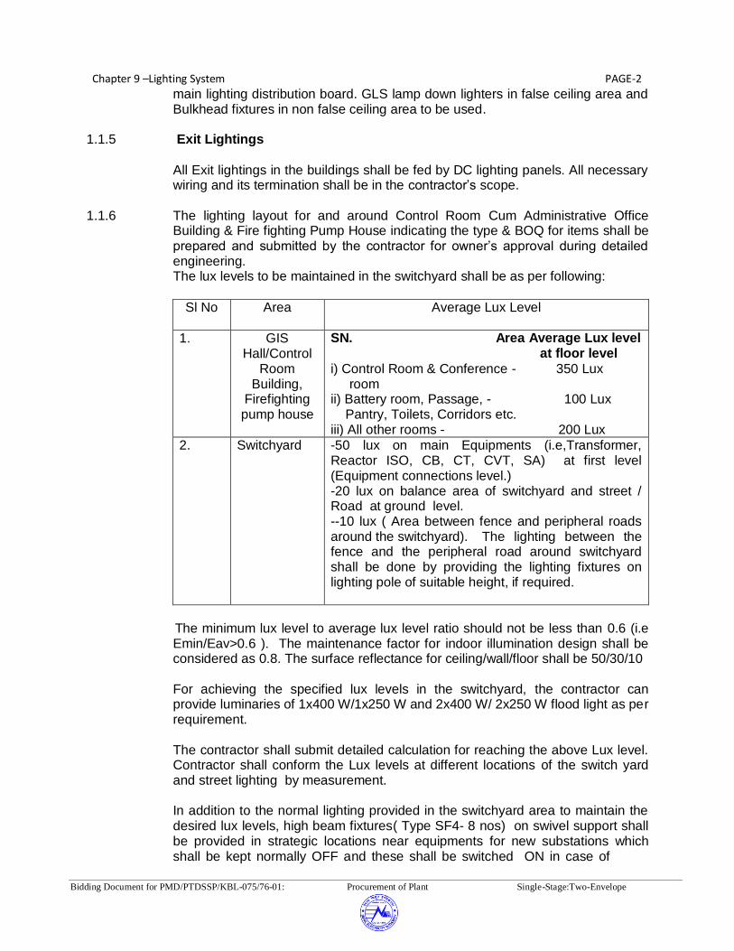
Chapter 9 –Lighting System PAGE-2
Bidding Document for PMD/PTDSSP/KBL-075/76-01: Procurement of Plant Single-Stage:Two-Envelope
main lighting distribution board. GLS lamp down lighters in false ceiling area and Bulkhead fixtures in non false ceiling area to be used.
1.1.5 Exit Lightings
All Exit lightings in the buildings shall be fed by DC lighting panels. All necessary wiring and its termination shall be in the contractor’s scope.
1.1.6 The lighting layout for and around Control Room Cum Administrative Office
Building & Fire fighting Pump House indicating the type & BOQ for items shall be prepared and submitted by the contractor for owner’s approval during detailed engineering. The lux levels to be maintained in the switchyard shall be as per following:
Sl No Area Average Lux Level
1. GIS Hall/Control
Room Building,
Firefighting pump house
SN. Area Average Lux level at floor level
i) Control Room & Conference - 350 Lux room ii) Battery room, Passage, - 100 Lux Pantry, Toilets, Corridors etc. iii) All other rooms - 200 Lux
2. Switchyard -50 lux on main Equipments (i.e,Transformer, Reactor ISO, CB, CT, CVT, SA) at first level (Equipment connections level.) -20 lux on balance area of switchyard and street / Road at ground level. --10 lux ( Area between fence and peripheral roads around the switchyard). The lighting between the fence and the peripheral road around switchyard shall be done by providing the lighting fixtures on lighting pole of suitable height, if required.
The minimum lux level to average lux level ratio should not be less than 0.6 (i.e
Emin/Eav>0.6 ). The maintenance factor for indoor illumination design shall be considered as 0.8. The surface reflectance for ceiling/wall/floor shall be 50/30/10
For achieving the specified lux levels in the switchyard, the contractor can
provide luminaries of 1x400 W/1x250 W and 2x400 W/ 2x250 W flood light as per requirement.
The contractor shall submit detailed calculation for reaching the above Lux level.
Contractor shall conform the Lux levels at different locations of the switch yard and street lighting by measurement.
In addition to the normal lighting provided in the switchyard area to maintain the
desired lux levels, high beam fixtures( Type SF4- 8 nos) on swivel support shall be provided in strategic locations near equipments for new substations which shall be kept normally OFF and these shall be switched ON in case of

Chapter 9 –Lighting System PAGE-3
Bidding Document for PMD/PTDSSP/KBL-075/76-01: Procurement of Plant Single-Stage:Two-Envelope
maintenance work. 1.1.7 Ceiling fans (1400 mm sweep, AC 230 volts ) shall be provided in , fire fighting
pump house and non AC rooms in the control room building as per the requirements. Wall mounted fans shall be provided in the conference room, control room, shift manager and substation incharge rooms in control room building. Exhaust fans shall be provided in toilets and pantry.
1.1.8 One no. of aluminum ladder of each size shall be supplied by the contractor for
maintenance purpose. 1.1.9 The following specific areas are included in the scope of lighting: (i) Switchyard Area.
(ii) Switchyard GIS Hall Building Control Room cum Administrative Office Building (As applicable)
(iii) Fire fighting pump house (As applicable) (iv) Street lighting (peripheral) inside switchyard fencing (Street lighting shall
be done using street lighting poles) v) LT Transformer area
1.1.10 For Outdoor Illumination
The switchyard and street lighting design including lux level calculations, surface illuminance diagram at varying equipment surface levels , detailed drawings showing the lighting layout and Electrical distribution diagram and BOQ for items shall be prepared by the Contractor and submitted for approval. The above layout drawings will include disposition and location of lighting fixtures, receptacles, etc.
1.1.11 For Indoor Illumination
The conduit layout drawing for substation buildings, Electrical distribution diagram for substation buildings, & for substation yard etc. shall be prepared by the Contractor. All wiring including telephone wiring (tinned two pair copper) shall be in concealed conduit. Concealed MS junction boxes for sockets and light points shall be provided in all the rooms of Control Room cum Administrative Office Building and Fire Fighting pump house. In case where false ceiling surface conducting is permissible, all down run conduits will be concealed in wall below the false ceiling.
1.1.12 Each cable run shall be tagged with number that appear in the cable schedules. Cables shall be tagged at their entrance and/or exit from any piece of equipment, junction or pull box, floor opening etc.
1.1.13 The tag shall be made up of aluminum with the number punched on it and
securely attached to the cable by not less than two turns of G.I. wire. Cable tags shall be rectangular in shape for power cables and circular shape for control cables.
1.1.14 Location of cables laid directly under ground shall be indicated clearly by cable
marker made of galvanised iron plate embedded in concrete block.

Chapter 9 –Lighting System PAGE-4
Bidding Document for PMD/PTDSSP/KBL-075/76-01: Procurement of Plant Single-Stage:Two-Envelope
1.1.15 The location of under ground cable joints if any, shall be clearly indicated with
cable marker with an additional inscription "cable joint". 1.1.16 The marker, which is a concrete block, shall project 150 mm above ground and
shall be spaced at an interval of 30 meters and at every change of direction. It shall also be located on both sides of the road or drain crossing.
2.0 DESCRIPTION OF ITEMS 2.1 DESCRIPTION OF ITEMS FOR SUBSTATION LIGHTING
The Contractor shall supply and install the following equipment and accessories
in accordance with the specification.
2.1.1 LIGHTING PANELS
2.1.1.1 OUTDOOR
400 AC lighting panel with 400V, 63A, 3 phase 4 wire bus and one no. 63A, TPN, MCB with neutral unit as incomer and 20A, SP MCB as outgoing feeders, the details are as follows.
Type of Panel Description Detail Of Outgoing Feeders
ACP 2 Outdoor 6 nos- 20 A single pole MCB and 3 No. 32 A Triple pole MCB with Neutral and suitable timer and contactor for automatic switching.
ACP 3 Outdoor Street lighting Panel
3 nos.-32A Triple pole MCB with Neutral with suitable timer and contactor for automatic switching
Note: The number of outgoing feeders indicated above are the minimum. 2.1.1.2 INDOOR
400 V indoor AC lighting panel ,63 A 3 phase 4 wire bus and one number 63 amp
FP MCB with 300ma 63 A FP RCCB. Flush mounted with per phase isolation and LED indication lamps . The DB will be flush mounted and double door type.
Type Of Panel Description Detail Of Outgoing Feeders
ACP 1 Indoor 18 nos outgoing ,16 Amps SP MCB
220V DC indoor type change over board and 220V DC 32A two wire bus and one
32A contractor backed up by 32A double pole MCB as incomer. The panel shall have local push button controls. Following are the various types of panels

Chapter 9 –Lighting System PAGE-5
Bidding Document for PMD/PTDSSP/KBL-075/76-01: Procurement of Plant Single-Stage:Two-Envelope
required with control timer.
Type Of Panel Description Detail Of Outgoing Feeders
DCP Indoor 6 nos outgoing ,16 Amps DP MCB
2.1.1.3 Sub-Lighting Panels
Type Of Panel Description Detail Of Outgoing Feeders
SLP Outdoor 4 pole 32A Isolator suitable for 400V, 50 cycles AC supply, wlith LILO facility using 8 nos terminal blocks suitable for cable upto 16 mm sq cable Enclosure shall be suitable for outdoor use with IP-55 degree of protection as per IEC:60529.
2.1.2 LIGHTING FIXTURES
Please Refer Annexure-1
2.1.3 RECEPTACLES
Type Of Receptacle Description Detail Of Outgoing Feeders
RO Outdoor 15A, 230V, Receptacle 2 pole, 3- pin type
RP Outdoor 63A, 400V, Interlocked switch socket, receptacle
RI Indoor 5/15A, 230V, Receptacle 3-pin type ( Modular)
2.1.4 (a) SWITCH BOARDS
Modular type switches, 5/15 Amp. Receptacles.
2.1.4 (b) CONDUITS AND ACCESSORIES
Galvanised Rigid steel or Rigid PVC conduits of 20/25 /32 mm for Lighting and
Telephone wiring
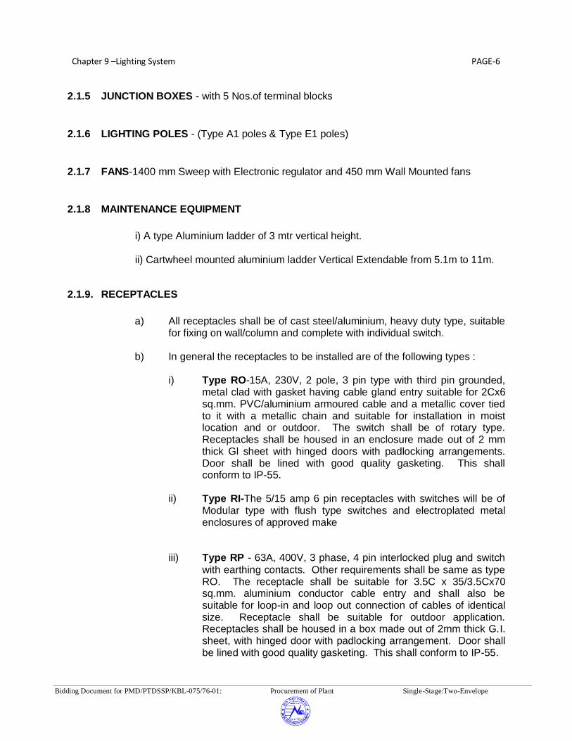
Chapter 9 –Lighting System PAGE-6
Bidding Document for PMD/PTDSSP/KBL-075/76-01: Procurement of Plant Single-Stage:Two-Envelope
2.1.5 JUNCTION BOXES - with 5 Nos.of terminal blocks
2.1.6 LIGHTING POLES - (Type A1 poles & Type E1 poles)
2.1.7 FANS-1400 mm Sweep with Electronic regulator and 450 mm Wall Mounted fans
2.1.8 MAINTENANCE EQUIPMENT
i) A type Aluminium ladder of 3 mtr vertical height.
ii) Cartwheel mounted aluminium ladder Vertical Extendable from 5.1m to 11m.
2.1.9. RECEPTACLES
a) All receptacles shall be of cast steel/aluminium, heavy duty type, suitable
for fixing on wall/column and complete with individual switch. b) In general the receptacles to be installed are of the following types :
i) Type RO-15A, 230V, 2 pole, 3 pin type with third pin grounded, metal clad with gasket having cable gland entry suitable for 2Cx6 sq.mm. PVC/aluminium armoured cable and a metallic cover tied to it with a metallic chain and suitable for installation in moist location and or outdoor. The switch shall be of rotary type. Receptacles shall be housed in an enclosure made out of 2 mm thick Gl sheet with hinged doors with padlocking arrangements. Door shall be lined with good quality gasketing. This shall conform to IP-55.
ii) Type RI-The 5/15 amp 6 pin receptacles with switches will be of
Modular type with flush type switches and electroplated metal enclosures of approved make
iii) Type RP - 63A, 400V, 3 phase, 4 pin interlocked plug and switch
with earthing contacts. Other requirements shall be same as type RO. The receptacle shall be suitable for 3.5C x 35/3.5Cx70 sq.mm. aluminium conductor cable entry and shall also be suitable for loop-in and loop out connection of cables of identical size. Receptacle shall be suitable for outdoor application. Receptacles shall be housed in a box made out of 2mm thick G.I. sheet, with hinged door with padlocking arrangement. Door shall be lined with good quality gasketing. This shall conform to IP-55.

Chapter 9 –Lighting System PAGE-7
Bidding Document for PMD/PTDSSP/KBL-075/76-01: Procurement of Plant Single-Stage:Two-Envelope
2.1.10. LIGHTING PANELS (L.P.)
2.1.10.1 Each panel shall be provided with one incoming triple pole MCB with neutral link
and outgoing miniature circuit breakers as per clause 2.0. The panels shall conform to IEC: 60439.
2.1.10.2 Constructional Features a) Panels shall be sheet steel enclosed and shall be dust, weather and vermin
proof. Sheet steel used shall be of thickness not less than 2.00 mm (cold rolled) smoothly finished, levelled and free from flaws. Stiffners shall be provided wherever necessary.The indoor lighting panels will be ready made DB of minimum 1.6 mm sheet thickness .
b) The panels shall be of single front construction, front hinged and front connected,
suitable for either floor mounting on channels, sills or on walls/columns by suitable M.S. brackets. Indoor panels in control room shall be flush mounted.
c) Panels shall have a dead front assembly provided with hinged door(s) and out
door panels will be with padlocking arrangement with single key supplied in duplicate.
d) All out door panels, removable covers, doors and plates shall be gasket all
around with neoprene gaskets. e) The outdoor panels shall be suitable for cable/conduit entry from the top and
bottom. Suitable removable cable gland-plate shall be provided on the top and bottom of panels. Necessary number of double compression cable gland shall be supplied, fitted on to this gland plate. The glands shall be screwed on top and made of tinned brass.
f) The panels shall be so constructed as to permit free access to connection of
terminals and easy replacement of parts. g) Each panel shall have a caution notice fixed on it. h) Each panel will be provided with directory holder in which printed and laminated
as built circuit directory would be kept inside a document holder/pasted at site. i) Each Outdoor lighting panel shall be provided with one no. ‘ON’ indicating lamp
for each phase alongwith fuses. For indoor lighting panels din mounted phase indication lamps will be provided, mounted along side of the MCB
j) Main Bus Bars Bus bars shall be of aluminium alloy conforming to IEC: 60114/60105 and shall
have adequate cross-section to carry the rated continuous and withstand short circuit currents. Maximum operating temperature of the bus bars shall not exceed 85 deg. C. The bus bars shall be able to withstand a fault level of 9 kA for 1 sec. for AC panels and 4 KA for 1 sec. for DC panels. The Indoor lighting

Chapter 9 –Lighting System PAGE-8
Bidding Document for PMD/PTDSSP/KBL-075/76-01: Procurement of Plant Single-Stage:Two-Envelope
panels shall have copper bus bar 2.1.10.3 JUNCTION BOXES
a) The junction boxes shall be concealed type for indoor lighting and suitable for
mounting on columns, lighting poles, structures etc., for outdoor lighting. b) Junction boxes shall be of square/rectangular type of 1.6 mm sheet steel with
minimum 6 mm thick pressure diecast aluminium material LM-6 and shall have bolted cover with good quality gasket lining.
c) The junction box and cover of sheet steel construction shall be hot dip
galvanised. d) The junction boxes shall be complete with conduit knockouts/threaded nuts and
provided with terminal strips .The junction boxes shall be suitable for termination of Cable glands of dia 20 mm, 25 mm, 32 mm, 40 mm on all sides. The junction boxes shall be provided with 4 way terminals suitable for two numbers 10 sq. mm. wire & for street lighting/switchyard lighting suitable for 2 numbers 4C x 16 Sq.mm Al. cable.
e) The junction boxes shall have the following indelible markings (i) Circuit Nos. on the top. (ii) Circuit Nos. with ferrules (inside) as per drawings. (iii) DANGER sign in case of 400 volt junction box. f) The junction boxes shall be weather proof type with gaskets conforming to IP 55
as per IEC: 60529. 2.1.10.4 Occupancy Sensors:
Sufficient number of occupancy sensors shall be provided in the stairs area and corridors of control room cum administrative building. Each occupancy sensor shall be used for indoor use with time delay programmable in the minimum range of 1 sec. to 2 Hour to control the illumination in the area.
2.2 DESCRIPTION OF COMMON ITEMS FOR LIGHTING 2.2.1 LIGHTING FIXTURES AND ACCESSORIES 2.2.1.1 General
All lighting fixtures and accessories shall be designed for continuous operation
under atmospheric conditions existing at site, without reduction in the life or without any deterioration of materials, internal wiring.
2.2.1.2 Temperature Rise
All lighting fixtures and accessories shall be designed to have a low temperature
rise according to the relevant International standard. The design ambient

Chapter 9 –Lighting System PAGE-9
Bidding Document for PMD/PTDSSP/KBL-075/76-01: Procurement of Plant Single-Stage:Two-Envelope
temperature shall be taken as 50 deg.C. 2.2.1.3 Supply Voltage
Lighting fixtures and accessories meant for 230V A.C. operation shall be suitable for operation on 230V A.C. 50Hz, supply voltage variation of ± 10%, frequency variation of ± 2.5% and combined voltage and frequency variation of ± 10%.
Lighting fixture and accessories meant for 220V DC operation shall be suitable
for operation on 220V DC with variation between 190 to 230 Volts. 2.2.1.4 Lighting Fixtures a) The lighting fixtures shall be Philips or equivalent International make except for
fixtures type ‘DSM’ & ‘HL’ for which make has been specified elsewhere in this chapter. The different types of lighting fixtures are also indicated elsewhere in this Chapter.
b) All fixtures shall be designed for minimum glare. The finish of the fixtures shall be
such that no bright spots are produced either by direct light source or by reflection.
c) All lighting fixtures shall be complete with fluorescent tubes / incandesent
lamps/mercury vapour/sodium vapour lamps as specified and shall be suitably wired up.
d) All flourescent lamp fixture shall be complete with all accessories like ballasts,
power factor improvement capacitors, lamps, starters, holders etc. e) High beam fixtures shall be suitable for pendant mounting and flood lights shall
have suitable base plate / frame for mounting on steel structural member. Hook mounted high beam fixtures are not acceptable.
f) Each lighting fixture shall be provided with an earthing terminal suitable for
connection to 16 SWG GI earthing conductors. g) All light reflecting surfaces shall have optimum light reflecting co-efficient such as
to ensure the overall light output as specified by the manufacturer. h) Height of fixtures should be such that it is easy to replace the lamps with normal
ladder/stool. In case the ceiling height is very high, the fixtures may be placed on the walls for ground lighting.
2.2.1.5 ACCESSORIES
2.2.1.5.1 Lamp holders and Starter Holders (a) Lamp holders/starter holders for fluorescent tubes shall be of the spring
loaded, low contact resistance, bi-pin rotor type, resistant to wear and suitable for operation at the specified temperature, without deterioration in insulation value, contact resistance or retention of the lamp/starter. They
Chapter 9 –Lighting System PAGE-10
Bidding Document for PMD/PTDSSP/KBL-075/76-01: Procurement of Plant Single-Stage:Two-Envelope
shall hold the lamp/starter in position under normal condition of shock and vibration.
(b) Lamp holders/starter for incandescent lamps and HPMV/HPSV lamps
shall be of screwed type, manufactured in accordance with relevant standard and designed to give long and satisfactory service.
2.2.1.5.2 Ballasts
a) All HPSV/HPMV/Metal halide lamp fixtures shall be provided with wire
wound ballasts. All fluorescent fixtures shall be provided with high frequency electronic ballasts. The Ballasts shall be designed, manufactured and supplied in accordance with relevant standard and function satisfactorily under site condition specified. The ballasts shall be designed to have a long service life and low power loss.
b) Ballasts shall be mounted using self locking anti-vibration fixing and shall
be easy to remove without dismantling the fixtures. They shall be totally enclosed units.
c) The wire-wound ballasts shall be of the inductive, heavy duty type, filled
with thermosetting insulating moisture repellent polyester compound filled under pressure or vacuum. The ballast wiring shall be of copper wire. They shall be free from hum. Ballasts which produce humming sound shall be replaced free of cost by the Contractor. Ballasts for high pressure mercury vapour/ HPSV lamps shall be provided with suitable tappings to set the voltage within the range specified. End connections and taps shall be brought out in a suitable terminal block, rigidly fixed to the ballast enclosure.
d) Separate ballast for each lamp shall be provided in case of multi-lamp
fixtures. e) High frequency electronic ballasts shall be capable of satisfactory
performance in adverse environment like that of EHV substation. Ballasts shall consist of AC/DC converter, high frequency power oscillator and low pass filter. The ballasts shall be suitable for use of nominal voltage of 230V +/- 10%, 50 Hz supply. The filter circuit shall suppress the feedback of high frequency signals to the mains. The ballast shall be rated for 36/40W fluorescent fixtures. The ballasts shall confirm to IEC 68-2-6FC, IEC 60929 for performance, IEC 60928 for safety and EN 55015, EN 55022A for RFI and EN 61003.
2.2.1.5.3 Capacitors a) The capacitors shall have a constant value of capacitance and shall be
connected across the supply of individual lamp circuits. b) Power factor of fluorescent lamp fixtures with HF electronic ballast shall
not be less than 0.90 and that of High pressure Sodium Vapour, Mercury Vapour and Metal Halide lamp fixtures shall not be less than 0.85. The capacitors shall be suitable for operation at supply voltage as specified

Chapter 9 –Lighting System PAGE-11
Bidding Document for PMD/PTDSSP/KBL-075/76-01: Procurement of Plant Single-Stage:Two-Envelope
and shall have a value of capacitance so as to correct the power factors of its corresponding lamp circuit to the extent of 0.98 lag.
c) The capacitors shall be hermetically sealed in a metal enclosure. 2.2.1.5.4 Lamps a) General Lighting Services (GLS) lamps shall be provided with screwed caps and
shall be of 'clear' type unless otherwise specified. b) The Bidder shall furnish typical wiring diagram for Fluorescent, HPMV & HPSV
fitting including all accessories. The diagram shall include technical details of accessories i.e. starters, chokes, capacitors etc.
c) Flexible conduits if required, for any fixture shall be deemed to be included in
Contractor’s scope. 2.2.1.5.5 SWITCH AND SWITCHBOARD
(a) All Switch board/boxes, 5/15 Amp Receptacles and electronic fan regulators located in office/building areas shall be modular flush mounted type or brick wall with only the switch knob projecting outside.
(b) Switch boards/boxes shall have conduit knock outs on all the sides.
(c) The exact number of switches including regulator for fans and layout of the same in the switchboard shall be to suit the requirement during installation.
(d) The maximum number of luminaires , controlled by one no 6 amp switch would 4 nos. For DC fixtures there will be no switch and the same shall be directly controlled from DC LP
(e) The luminaires shall be wired in such a fashion that luminaires on each phase are evenly distributed all over the room.
2.2.1.5.6. CONDUITS & CONDUIT ACCESSORIES
a) The conduits shall conform to IEC: 61386 or IEC: 61035 or IEC: 60614 as
applicable. All steel conduits shall be seemed by welding, shall be of heavy gauge and shall be hot dip galvanised.
b) Flexible conduits wherever required shall be made with bright, cold rolled
annealed and electro-galvanised mild steel strips or PVC/Plastic. c) All conduits accessories shall conform to relevant IEC and shall be hot dip
galvanized or High quality virgin PVC. 2.2.1.5.7 TERMINAL BLOCKS Each terminal shall be suitable for terminating upto 2 Nos. 10 sq.mm. stranded

Chapter 9 –Lighting System PAGE-12
Bidding Document for PMD/PTDSSP/KBL-075/76-01: Procurement of Plant Single-Stage:Two-Envelope
Aluminium Conductors without any damage to the conductors or any looseness of connections. Terminal strips provided in street - lighting poles shall be suitable for terminating upto 2 nos. 4C x 16 sq. mm aluminium cables.
2.2.1.5.8 PULL OUT BOXES
a) The pull out boxes shall be concealed type for indoor lighting and suitable for
mounting on column, structures etc., for outdoor lighting. The supply of bolts, nuts and screws required for the erection shall be included in the installation rates.
b) The pull out boxes shall be circular of cast iron or 16 SWG sheet steel and shall
have cover with good quality gasket lining. c) The pull out boxes and cover shall be hot dip galvanised. d) The pull out boxes shall be completed with conduit knock outs/threaded hubs
and provided at approximately 3 meters intervals in a conduit run. 2.2.1.5.9 Residual Current Circuit Breakers (RCCB)
For indoor panels 63A 4pole 300 ma RCCB conforming IEC 13947 will be
provided along with incomer. 2.2.1.5.10 Miniature Circuit Breaker (MCB)
a) The miniature circuit breakers shall be suitable for manual closing,
opening, automatic tripping under overload and short circuit. The MCBs shall also be trip free. MCB of Type C tripping characteristics as per IEC: 60898 will be used for Switchyard lighting.
b) Single pole as well as three pole versions shall be furnished as required
in the Schedule of Lighting Panels. c) The MCBs and panel MCCB together shall be rated for full fault level. In
case the MCB rating is less than the specified fault level the bidder shall co-ordinate these breaker characteristics with the back up MCCB in such a way that if fault current is higher than breaker rating, the MCCB should blow earlier than the breaker. If the fault current is less than MCB breaking capacity, MCB shall operate first and not the incomer MCCB.
d) The MCBs shall be suitable for housing in the lighting panels and shall be
suitable for connection with stranded copper wire connection at both the incoming and outgoing side by copper lugs or for bus bar connection on the incoming side.
e) The terminals of the MCBs and the ‘open’ ‘close’ and ‘trip’ conditions shall
be clearly and indelibly marked. f) The tenderer shall check and co-ordinate the ratings of MCBs with
respect to starting characteristics of discharge lamps. The vendor has to

Chapter 9 –Lighting System PAGE-13
Bidding Document for PMD/PTDSSP/KBL-075/76-01: Procurement of Plant Single-Stage:Two-Envelope
furnish overload and short circuit curve of MCB as well as starting characteristics curves of lamps for Employer’s approval.
g) The MCB shall generally conform to IEC: 60898. 2.2.1.5.11 Contactors Contactors shall be of the full voltage, direct-on line air break, single throw,
electro-magnetic type. They shall be provided with atleast 2-’NC’ and 2’NO’ auxiliary contacts. Contactor shall be provided with the three element, positive acting, ambient temperature compensated time lagged, hand reset type thermal overload relay with adjustable settings to suit the rated current. Hand reset button shall be flush with the front of the cabinet and suitable for resetting with starter compartment door closed. The Contactor shall be suitable for switching on Tungsten filament lamp also. The bidder shall check the adequacy of the Contactors rating wire with respect to lighting load.
2.2.1.5.12 Push Buttons
All push buttons shall be of push to actuate type having 2 ‘NO’ and 2 ‘NC’ self
reset contacts. They shall be provided with integral escutcheon plates engraved with their functions. Push buttons shall be of reputed make.
2.2.1.5.13 Labels
a) The lighting panels shall be provided on the front with panel designation
labels on a 3 mm thick plastic plate of approved type. The letter shall be black engraved on white back ground.
b) All incoming and outgoing circuits shall be provided with labels. Labels
shall be made of non-rusting metal or 3 ply lamicold. Labels shall have white letters on black or dark blue background.
2.2.1.5.14 Earthing Terminals
Panels shall be provided with two separate and distinct earthing terminals
suitable to receive the earthing conductors of size 50x6 G.S. Flat. 2.2.1.5.15 Type test reports for following tests on all lighting panels shall be submitted for
approval as per clause 9.2 of Chapter 2: GTR. (i) Wiring continuity test (ii) High voltage (2.5 KV for 1 minute) and insulation test (iii) Operational test
(iv) Degree of protection (not less than IP-55 test on outdoor Lighting Panels and IP-52 test on indoor Lighting Panels as per IEC: 60947 (part 1)
(v) Heat run test
2.2.1.5.16. LIGHTING POLES

Chapter 9 –Lighting System PAGE-14
Bidding Document for PMD/PTDSSP/KBL-075/76-01: Procurement of Plant Single-Stage:Two-Envelope
a) The Contractor shall supply, store and install the following types of steel tubular lighting poles required for street lighting.
i) Type A1 Street Lighting Pole - for one fixture ii) Type E1 Post top lantern pole - for one fixture b) Street/flood light poles shall conform to the enclosed drawings. In front of control
room building , and Fire Fighting Buildings, decorative post top lantern (Type E1) poles and Bollards shall be installed.
c) Lighting poles shall be complete with fixing brackets and junction boxes.
Junction boxes should be mounted one meter above ground level. d) The lighting poles shall be coated with bituminous preservating paint on the
inside as well as on the embedded outside surface. Exposed outside surface shall be coated with two coats of metal primer (comprising of red oxide and zinc chromate in a synthetic medium).
e) The galvanised sheet steel junction box for the street lighting poles shall be
completely weather proof conforming to IP-55 and provided with a lockable door and HRC fuse mounted on a fuse carrier and fuse base assembly. The fuses & junction box shall be as specified in the specification. However, terminals shall be stud type and suitable for 2 nos. 16 sq.mm. cable.
f) Wiring from junction box at the bottom of the pole to the fixture at the top of the
pole shall be done through 2.5 sq. mm wire. g) Distance of centre of pole from street edge should be approximately 1000 to
1200 mm. h) Earthing of the poles should be connected to the switchyard main earth mat
wherever it is available and the same should be earthed through 3M long, 20 mm dia, earth electrode.
2.2.1.5.17 CEILING & WALL MOUNTED FANS AND REGULATORS
a) The contractor shall supply and install 1400 mm sweep ceiling fans complete with electronic regulator and switch, suspension rod, canopy and accessories. The wall mounted fans shall be of 400 mm sweep
b) The contractor shall supply and install the switch, electronic regulator and board
for mounting switch and electronic regulator for celling fans. The regulator will be housed in common switchboard for lighting and shall be of similar make and model as that of modular switches.
c) Winding of the fans and regulators shall be insulated with Class-E insulating
material. Winding shall be of copper wire. d) Electronic regulator with stepped control shall be provided.

Chapter 9 –Lighting System PAGE-15
Bidding Document for PMD/PTDSSP/KBL-075/76-01: Procurement of Plant Single-Stage:Two-Envelope
2.2.1.5.18 LIGHTING WIRES
a) The wiring used for lighting shall be standard products of reputed manufacturers. b) The wires shall be of 1100 V grade, PVC insulated product of reputed
manufacturers. c) The conductor sizes for wires used for point wiring beyond lighting panels shall
be 2.5 sq.mm, 4 sq.mm, 6 sq.mm and 1.5 sq.mm stranded copper wire. d) The wires used for connection of a lighting fixture from a nearest junction box or
for loop-in loop-out connection between two fluorescent fixtures shall be single core copper stranded conductor, 1100V grade flexible PVC insulated cords, unsheathed, conforming to IEC:60502 with nominal conductor cross sectional areas of 2.5 sq. mm.
e) The wires shall be colour coded as follows: Red for R - Phase Yellow for Y - Phase Blue for B - Phase Black for Neutral White for DC (Positive) Grey for DC (Negative)
2.2.1.5.19 LIGHTING SYSTEM INSTALLATION WORKS
2.2.1.5.19.1 General
In accordance with the specified installation instructions as shown on
manufacturer’s drawings or as directed by Employer, Contractor shall unload, erect, install, test and put into commercial use all the electrical equipment included in the contract. Equipment shall be installed in a neat, workmanship manner so that it is level, plumb square and properly aligned and oriented. Tolerances shall be as established in manufacturers drawing or as stipulated by Purchaser.
All apparatus, connections and cabling shall be designed so as to minimize risk
of fire or any damage which will be caused in the event of fire. 2.3.1.5.19.2 Conduit System
a) Contractor shall supply, store and install conduits required for the lighting
installation as specified. All accessories/fittings required for making the installation complete, including but not limited to pull out boxes (as specified in specification ordinary and inspection tees and elbow, checknuts, male and female bushings (brass or galvanised steel), caps, square headed make plugs, nipples, gland sealing fittings, pull boxes, conduits terminal boxes, glands,
Chapter 9 –Lighting System PAGE-16
Bidding Document for PMD/PTDSSP/KBL-075/76-01: Procurement of Plant Single-Stage:Two-Envelope
gaskets and box covers, saddle terminal boxes, and all steel supporting work shall be supplied by the Contractor. The conduit fittings shall be of the same material as conduits. The contractor shall also supply 20 mm PVC conduit and accessories for telephone wiring.
b) All unarmoured cables/wires shall run within the conduits from lighting panels to
lighting fixtures, receptacles. etc. c) Size of conduit shall be suitably selected by the Contractor. d) Conduit support shall be provided at an interval of 750 mm for horizontal runs
and 1000 mm for vertical runs. e) Conduit supports shall be clamped on the approved type spacer plates or
brackets by saddles or U-bolts. The spacer plates or brackets in turn, shall be securely fixed to the building steel by welding and to concrete or brick work by grouting or by nylon rawl plugs. Wooden plug inserted in the masonary or concrete for conduit support is not acceptable.
f) Where conduits are along with cable trays they shall be clamped to supporting
steel at an interval of 600 mm. g) For directly embedding in soil, the conduits shall be coated with an asphalt-base
compound. Concrete pier or anchor shall be provided wherever necessary to support the conduit rigidly and to hold it in place.
h) For long conduit run, pull boxes shall be provided at suitable intervals to facilitate
wiring. i) Conduit shall be securely fastened to junction boxes or cabinets, each with a lock
nut inside and outside the box. j) Conduits joints and connections shall be made through water-tight and rust proof
by application of a thread compound which insulates the joints. White lead is suitable for application on embedded conduit and red lead for exposed conduit.
k) The entire metallic/PVC conduit system, shall be embedded, electrically
continuous and thoroughly grounded. Where slip joints are used, suitable bounding shall be provided around the joint to ensure a continuous ground circuit.
l) Conduits and fittings shall be properly protected during construction period
against mechanical injury. Conduit ends shall be plugged or capped to prevent entry of foreign material.
2.2.1.5.19.3 Wiring
a) Wiring shall be generally carried out by PVC insulated wires in conduits. All
wires in a conduit shall be drawn simultaneously. No subsequent drawings of

Chapter 9 –Lighting System PAGE-17
Bidding Document for PMD/PTDSSP/KBL-075/76-01: Procurement of Plant Single-Stage:Two-Envelope
wires is permissible. b) Wires shall not be pulled through more than two equivalent 90 deg. bends in a
single conduit run. Where required, suitable junction boxes shall be used. c) Wiring shall be spliced only at junction boxes with approved type terminal strip. d) For lighting fixtures, connection shall be teed off through suitable round conduit
or junction box, so that the connection can be attended without taking down the fixture.
e) For vertical run of wires in conduit, wires shall be suitably supported by means of
wooden/hard rubber plugs at each pull/junction box. f) Maximum two wires can be terminated to each way of terminal connections. g) Separate neutral wires are to be provided for each circuit. h) AC and DC wiring should not run through the same conduit. 2.2.1.5.19.4 Lighting Panels
a) The lighting panels shall be erected at the locations to be finalised during
detailed engineering. b) Suitable foundations/supporting structures for all outdoor type lighting panels
shall be provided by the Contractor. 2.2.1.5.19.5 Foundation & civil works a) Foundation for street lighting poles, panel foundation and transformer foundation
shall be done by the Contractor. The payment towards execution, PCC & RCC shall be made under relevant items of civil work mentioned in Bid Price schedule.
b) All final adjustment of foundation levels, chipping and dressing of foundation
surfaces, setting and grouting of anchor bolts, sills, inserts and flastening devices shall be carried out by the Contractor including minor modification of civil works as may be required for erection.
c) Any cutting of masonary / concrete work, which is necessary shall be done by the
Contractor at his own cost and shall be made good to match the original work.

Chapter 9 –Lighting System PAGE-18
Bidding Document for PMD/PTDSSP/KBL-075/76-01: Procurement of Plant Single-Stage:Two-Envelope
ANNEXURE-1
SI. No. Type of Lighting Fixture
Description Philips Catalogue No
1
F1 2x28W T5 type fluorescent lamps in industrial reflector type fixture, complete with accessories and suitable for pendent /surface mounting.
TMS 122/228 HF
2 FF 2x28 T5 energy efficient fluorescent lamps with low glare, mirror optics suitable for recess mounting type lighting fixture.
TBS 088/228 C5 HF
3 FL 2x28W T5 energy efficient fluorescent lamps with low glare mirror optics suitable for pendent/surface mounting with all accessories
TCS 398/228 D6 HF
4 TL Sleek and Functional electronic decobatten suitable for use with 1x'TLD'36W fluorescent lamp with dual tone end caps. Pre-phosphated & powder coated CRCA steel channel complete with all electrical accessories like electronic ballast, lamp holders all prewired up to a terminal block
TMS500/136 HF
5 IB 60/100w GLS lamp in Bulkhead fixtures with Cast Aluminium alloy body, suitable for column, wall,and ceiling mounting finished stove enameled silver grey outside
NXC101
6 BL Aesthetic wall/ceiling mounted luminaire suitable for 1x PL-C 13W OR 11W CFL. Low loss O.C. Copper ballast.Built in high gloss anodized reflector. Twin finish UV stabilised SAN diffuser for protection & elimination of lamp glare.
FMC21/113
7 SL Aesthetic ceiling mounted luminaire for Ecotone crystal/Décor CFL of 2x9W or 1x18W. ABS housing pre-wired with porcelain lampholder. Pre-phospated plated CRCA gear tray.
FL343/118

Chapter 9 –Lighting System PAGE-19
Bidding Document for PMD/PTDSSP/KBL-075/76-01: Procurement of Plant Single-Stage:Two-Envelope
SI. No. Type of Lighting Fixture
Description Philips Catalogue No
8 BH Bulkhead luminaire suitable for use with PL-S 9W CFL. Single piece pressure die-cast aluminium & cover retaining Frame. Opal acrylic cover along with a gasket made of E.P.R..
FXC 101/109
9 BLD 2X9 Or 1x18 watt CFL bollard light for landscape lighting having FRP/LLDPE housing
FGC202 /118
10 DLR 2x18 watt CFL Downlighter with HF ballast suitable for recess mounting
FBH145/218L HF
11 DSM 1X13 WATT surface mounted CFL FCS100/113
12 IF Incandescent GLS lamp down light DN622
13 SF1 1 X 400W HPSV lamps in high flood lighting fixture with integral control gear
SWF 330/1X400
14 SF2 2 X 400W HP sodium Vapour lamps in high flood lighting, non-integral control gear:
RVP302/2x400W
15 SF3 1 X 250W HPSV lamps in high flood lighting fixture with integral control gear:
SWF 330/1X250
16 SF4 150W HP Metal halide MHN-TD lamp in flood lighting fixture with integral control gear.
SWF230/150 MHN-TD
17 SF5 125 HP MV Lamp in weather proof post top lantern for mounting on pole top
HPC-101/125 HPF
18 SC 150W SON-T Tubular Sodium Vapour lamp in street lighting luminaire with toughned glass cover.
SRX-51/150

Chapter 10 –Air Conditioning System PAGE-1
Bidding Document for PMD/PTDSSP/KBL-075/76-01: Procurement of Plant Single-Stage:Two-Envelope
CHAPTER-10
AIR CONDITIONING SYSTEM
1 GENERAL
1.1 This specification covers supply, installation, testing and commissioning and
handing over to NEA of Air conditioning system for the control room building
and switch-yard panel rooms.
1.2 Air conditioning units for control room building shall be set to maintain the
inside DBT at 24 o C ± 2
oC and the air conditioning system for switch-yard
panel rooms shall be set to maintain DBT inside switch-yard panel rooms
below 24oC.
1.3 Controllers shall be provided in Control room and Battery room for controlling
and monitoring the AC units in these rooms as detailed in clause no.2.3.4.
1.4 Each switch-yard panel room shall be provided with temperature transducer
to monitor the temperature of the panel room. The Temperature transducer
shall have the following specification:
Sensor : Air temperature sensor (indoor use)
Output : 4 to 20mA
Temperature range : -5oC to 60
oC
Resolution : 0.1oC
Accuracy : 0.5oC or better.
2 AIR CONDITIONING SYSTEM FOR GIS/CONTROL ROOM BUILDING.
2.1 Air conditioning requirement of control room building shall be met using a
combination of following types Air Conditioning units as required.
a) Ductable Split unit of 8.5TR.
b) Cassette type split AC units of 3TR.
c) High wall type split AC units of 2TR.
2.2 Scope
The scope of the equipment to be furnished and services to be provided
under the contract are outlined hereinafter and the same is to be read in
conjunction with the provision contained in other sections/ clauses. The
scope of the work under the contract shall be deemed to include all such
items, which although are not specifically mentioned in the bid documents
and/or in Bidder's proposal, but are required to make the equipment/system
complete for its safe, efficient, reliable and trouble free operation.

Chapter 10 –Air Conditioning System PAGE-2
Bidding Document for PMD/PTDSSP/KBL-075/76-01: Procurement of Plant Single-Stage:Two-Envelope
2.2.1 Required number of Ductable split type AC units of 8.5 TR capacity with air
cooled outdoor condensing unit with semi hermetic/hermetic compressors
including refrigerant pipes, controls, thermostats, filters, outlet dampers, etc.
2.2.2 Required number of Cassette type split AC units of 3TR capacity each
complete with air cooled outdoor condensing unit having hermetically sealed
compressor unit with cordless remote controller.
2.2.3 Required number of High wall type split AC units of 2TR capacity each
complete with air cooled outdoor condensing unit having hermetically sealed
compressor and high wall type indoor evaporator unit with cordless remote
controller.
2.2.4 Copper refrigerant piping complete with insulation between the indoor and
outdoor units as required.
2.2.5 First charge of refrigerant and oil shall be supplied with the unit.
2.2.6 GSS/Aluminium sheet air distribution ducting for distributing conditioned
dehumidified air along with supply air diffusers and return air grilles with
volume control dampers and necessary splitters etc., suitable fixtures for
grilles/diffusers and supports for ducting complete with insulation.
2.2.7 Local start/stop facility for local starting/ stopping of all electrical equipment/
drives.
2.2.8 All instruments and local control panels alongwith controls and interlock
arrangements and accessories as required for safe and trouble free
operation of the units.
2.2.9 PVC drain piping from the indoor units upto the nearest drain point.
2.2.10 Supply and erection of Power and control cable and earthing.
2.2.11 MS Brackets for outdoor condensing units, condensers as required.
2.3 Technical specifications.
2.3.1 Ductable split type AC units.
2.3.1.1 Each Split Air conditioner shall have an indoor unit and an outdoor unit,
designed to provide free delivery of conditioned air to the conditioned space.
The indoor unit shall be suitable for mounting on the ceiling concealed above
the false ceiling. Outdoor unit can be placed on the roof. Each unit shall
include a primary source of refrigeration for cooling and dehumidification,
means for circulation and cleaning air.

Chapter 10 –Air Conditioning System PAGE-3
Bidding Document for PMD/PTDSSP/KBL-075/76-01: Procurement of Plant Single-Stage:Two-Envelope
2.3.1.2 Cabinet The cabinets housing the components of indoor units & outdoor units shall be
of heavy gauge sheet steel and suitable for floor mounting/mounting from ceiling. The access panels shall be of easily removable type. The entire casing shall be lined with 25mm thick insulation of totally flame proof type. Suitable drain connection shall be provided for removal of condensate collected inside a tray under cooling coil.
2.3.1.3 Compressor The compressor shall be Semi hermetically/hermetically sealed type and
complete with drive motor. The compressor shall be mounted on spring inside the lower most section of the unit so that it is easily accessible for servicing.
2.3.1.4 Condenser Air cooled condenser of adequate surface area shall be offered. The air
cooled condenser shall be made of copper tubes with external fins.
2.3.1.5 Air Handling Fan The air handling fan shall be centrifugal type complete with belt drive and
electric motor.
2.3.1.6 Filter Pre-filter at the suctions to remove dust particles down to 10 micron size with
90% efficiency and fine filters to remove dust particles down to 5 micron size with 99% efficiency at the outlet. All filters shall be of panel type.
2.3.1.7 Cooling Coil Cooling coils shall be of direct expansion type and made of heavy gauge
copper with aluminium fins. Rows shall be staggered in the direction of air flow. Separate tubings from the distributor shall feed refrigerant uniformly to different sections of the coil.
2.3.1.8 Refrigerant Piping Refrigerant piping shall be of heavy gauge copper, heavy class seamless
M.S. pipe complete with thermostatic expansion valve, liquid strainer, dehydrator, liquid line shut off valve, high and low pressure gauges.
2.3.1.9 Condensate Trays An adequate method of condensate removal shall be provided. Condensate
tray of adequate size, made of corrosion-resistant material or suitably treated with corrosion-resistant coating shall be provided. The tray shall be

Chapter 10 –Air Conditioning System PAGE-4
Bidding Document for PMD/PTDSSP/KBL-075/76-01: Procurement of Plant Single-Stage:Two-Envelope
adequately insulated to avoid condensation over its external surface.
2.3.1.10 Refrigerant Strainer A refrigerant strainer shall be provided in the liquid line immediately before
the expansion device.
2.3.1.11 Vibration Isolator A minimum of six 25 thick neoprene rubber pads shall be supplied for each
unit.
2.3.1.12 Cooling capacity of 8.5TR unit shall not be less than 102000 btu/hr.
2.3.2 Cassette type split AC units.
The Cassette type AC units shall be complete with indoor evaporator unit,
outdoor condensing units and cordless remote control units.
2.3.2.1 Outdoor unit shall comprise of hermetically/ semi hermetically sealed
compressors mounted on vibration isolators, fans and copper tube aluminium
finned coils all assembled in a sheet metal casing. The casing and the total
unit shall be properly treated and shall be weatherproof type. They shall be
compact in size and shall have horizontal discharge of air.
2.3.2.2 Indoor units shall be of 4-way, ceiling mounted cassette type. The indoor unit
shall be compact and shall have elegant appearance. They shall have low
noise centrifugal blowers driven by suitable motors and copper tube
aluminium finned cooling coils. Removable and washable polypropylene
filters shall be provided. They shall be complete with multi function cordless
remote control unit with special features like programmable timer, sleep
mode etc.
2.3.2.3 Cooling capacity of 3TR AC units shall not be less than 36000btu/hr. and
their EER shall not be less than 2.7.
2.3.3 High wall type split AC units
2.3.3.1 The split AC units shall be complete with indoor evaporator unit, outdoor
condensing units and cordless remote control units.
2.3.3.2 Outdoor unit shall comprise of hermetically/semi hermetically sealed
compressors mounted on vibration isolators, propeller type axial flow fans
and copper tube aluminium finned coils all assembled in a sheet metal
casing. The casing and the total unit shall be properly treated and shall be
weatherproof type. They shall be compact in size and shall have horizontal

Chapter 10 –Air Conditioning System PAGE-5
Bidding Document for PMD/PTDSSP/KBL-075/76-01: Procurement of Plant Single-Stage:Two-Envelope
discharge of air.
2.3.3.3 The indoor units shall be high wall type. The indoor unit shall be compact and
shall have elegant appearance. They shall have low noise centrifugal
blowers driven by suitable motors and copper tube aluminium finned cooling
coils. Removable and washable polypropylene filters shall be provided. They
shall be complete with multi function cordless remote control unit with special
features like programmable timer, sleep mode and soft dry mode etc.
2.3.3.4 Cooling capacity of 2TR AC units shall not be less than 22000btu/hr. and
shall have energy efficiency rating of 3star or above.
2.3.4 Controllers shall be provided in Control room and Battery room, one
controller for each room, to control and monitoring of AC units and shall
have the following facilities;
Standby units shall come in to operation automatically when the running
main unit fails
Main and standby units shall be changed over periodically which shall be
finalised during detailed engineering.
Following alarms shall be provided:
a. Compressor On/OFF condition of each unit
b. Compressor failure of each unit
c. Power OFF to AC unit
d. High temperature in room.
2.4 Warranty
All compressors shall have minimum 5 years Warranty from the date of
commissioning.

Chapter 11 –Fire Protection System PAGE-1
Bidding Document for PMD/PTDSSP/KBL-075/76-01: Procurement of Plant Single-Stage:Two-Envelope
CHAPTER 11: FIRE PROTECTION SYSTEM
1.00.00 INTENT OF SPECIFICATION
This section covers the design and performance requirements of the following types
of fire protection systems; a. Hydrant System b. High Velocity Water (H.V.W) Spray System c. Fire Detection and alarm System d. Portable Fire Extinguishers e. Wheel/ Trolley mounted Fire Extinguishers 1.00.01 It is not the intent to completely specify all details of design and construction.
Nevertheless, the system design and equipment shall conform in all respects to high standard of engineering, design and workmanship and shall be capable of performing in continuous commercial operation in a manner acceptable to the Owner. The system design shall also conform to NFPA norms.
1.00.02 The scope of work include complete earthwork (i.e. excavation, backfilling etc.) for
the entire buried piping for the system, valve pits and pipe supports for buried, entrenched and overground piping.
1.00.03 The equipment offered shall comply with the relevant latest International Standards
unless specified otherwise. The Deluge valves, HVW spray nozzles & quartzoid
bulb detectors shall have the approval of any of the following agencies; a. UL of USA. b. F M of USA c. LPCB of UK or d. VDS of Germany, 1.00.04 Ambient temperature for design of all equipment shall be considered as 50°C. 1.00.05 The piping and instruments diagram for Hydrant and HVW spray system for 400kV
switchyard is enclosed at Appendix-I. respectively. The successful bidder shall prepare detailed layout and piping drawing based on this drawing and other drawings such as road, drainage, cable trench, switch yard layout, etc. as furnished by the Employer during detailed engineering.
2.00.00 DESIGN AND CONSTRUCTION 2.01.00 Hydrant System
Hydrant system of fire protection essentially consists of a large network of pipe,
both under ground and over ground which feeds pressurised water to a number of hydrant valves, indoor (if applicable) as well as outdoor. These hydrant valves are

Chapter 11 –Fire Protection System PAGE-2
Bidding Document for PMD/PTDSSP/KBL-075/76-01: Procurement of Plant Single-Stage:Two-Envelope
located at strategic locations near buildings, Transformers and Reactors. Hose pipes of suitable length and fitted with standard accessories like branch pipes, nozzles etc., are kept in Hose boxes. In case of emergency, these hoses are coupled to the respective hydrant valves through instantaneous couplings and jet of water is directed on the equipment on fire. Hydrant protection shall be provided for the following in all substations of voltage levels 132kV and above (This is not applicable for extension of existing 220kV and 132kV substations where Hydrant system is not available). At least one hydrant post shall be provided for every 60m of external wall measurement of buildings.
a) Control room building/ GIS Hall Building b) L.T. Transformer area c) Fire Fighting pump House. d) Stores e) Transformers
f) Shunt Reactors/ Bus Reactors. 2.01.01 A warning plate shall be placed near the hydrant points for the transformers and
reactors substations to clearly indicate that water shall be sprayed only after ensuring that the power to the transformer/ reactor which is on fire is switched off and there are no live parts within 20 metres of distance from the personnel using the hydrant.
2.02.00. HIGH VELOCITY WATER (H.V.W) SPRAY SYSTEM
H.V.W. spray type fire protection essentially consists of a network of projectors and
an array of heat detectors around the Transformer/Reactor to be protected. On operation of one or more of heat detectors, Water under pressure is directed to the projector network through a Deluge valve from the pipe network laid for this system. This shall be provided for transformers and reactors in all 132kV & above substations (This is not applicable for extension of existing 220kV and 132kV substations where HVWS system is not available). Wet detection initiation system shall be employed for automatic operation.
The system shall be designed in such a way that the same can be extended to pro-
tect additional Transformer/ Reactor to be installed in future. However, for the purpose of design it shall be assumed that only one Transformer/ Reactor will be on fire. The main header pipe size in the yard shall be 250mmNB (for 400kV switchyard) and 200mmNB (for 220kV & 132kV switchyard). Branch to the equipment (shall not be more than 20metres length) shall be of the same size as of deluge valve.
2.02.01 The Electrical clearance between the Emulsifier system pipe work and live parts of
the protected equipment shall not be less than the values given below: 1. 420 kV bushing 3500 mm 2. 245 kV bushing 2150 mm 3. 145 kV bushing 1300 mm

Chapter 11 –Fire Protection System PAGE-3
Bidding Document for PMD/PTDSSP/KBL-075/76-01: Procurement of Plant Single-Stage:Two-Envelope
4. 52 kV bushing 630 mm 5. 36/11 kV bushing 320 mm 2.02.02 System shall be designed in such a way that the Water pressure available at any
spray nozzle shall be between 3.5bar and 5.0bar and shall be demonstrated through hydraulic calculations. Water shall be applied at a minimum rate of 10.2 LPM/M2 of the surface area of the transformer / Reactor including radiator, conservator, oil pipes, bushing turrets, etc. (including bottom surface for transformer). The nozzle arrangement shall ensure direct impingement of water on all exterior surfaces of transformer tank, bushing turrets, conservator and oil pipes, except underneath the transformer, where horizontal spray may be provided.
2.02.03 Deluge Valve
Deluge Valve shall be water pressure operated manual reset type. The Deluge
valve shall be closed water tight when water pressure in the heat detector pipe work is healthy and the entire pipe work shall be charged with water under pressure upto the inlet of the Deluge valve. On fall of water pressure due to opening of one or more heat detectors, the valve shall open and water shall rush to the spray water network through the open Deluge valve. The valves shall be manually reset to initial position after completion of operation. Each Deluge Valve shall be provided with a water motor gong which shall sound an alarm when water after passing through the Deluge valve, is tapped through the water motor.
Each Deluge valve shall be provided with a local panel with provision of opening of
Deluge valve from local and remote from control room/ remote centre. In addition to this, each valve shall be provided with local operation latch.
Deluge valves of 100mmNB size shall be used if the flow requirement is ≤ 200m3/hr
and 150mmNB size shall be used for flow requirement >200m3/hr. Test valves shall simulate the operation of Deluge valves and shall be of quick
opening type. The general construction shall conform to requirements under clause no.7.00.00 for piping, valves and specialities.
2.02.04 High Velocity Spray Nozzles (Projectors)
High velocity spray system shall be designed and installed to discharge water in the
form of a conical spray consisting of droplets of water travelling at high velocity, which shall strike the burning surface with sufficient impact to ensure the formation of an emulsion. At the same time the spray shall efficiently cut off oxygen supply and provide sufficient cooling.
2.02.05 Minimum set point of the heat detectors used in the HVW spray system shall be
79oC. The optimum rating shall, however, be selected by the Bidder, keeping in mind the maximum and minimum temperature attained at site.
2.03.00 Fire Detection and alarm System

Chapter 11 –Fire Protection System PAGE-4
Bidding Document for PMD/PTDSSP/KBL-075/76-01: Procurement of Plant Single-Stage:Two-Envelope
This system shall be provided for control room building and Switchyard panel rooms of substations.
2.03.01 Suitable fire detection system using smoke detectors and/or heat detectors shall be
provided for the entire building, including corridor and toilets. Fire detectors shall be located at strategic locations in various rooms of the building. Each Switchyard panel room shall be considered a separate zone. Adequate number of extra zones shall be provided for Switchyard panel rooms for future bays identified in Single line diagram of the substation. The operation of any of the fire detectors/ manual call point should result in the following;
1. A visual signal exhibited in the annunciation panels indicating the area where
the fire is detected. 2. An audible alarm sounded in the panel, and 3. An external audible alarm sounded in the building, location of which shall be
decided during detailed engineering. 4. If the zone comprises of more than one room, a visual signal shall be
exhibited on the outer wall of each room. 2.03.02 Each zone shall be provided with two zone cards in the panel so that system will
remain healthy even if one of the cards becomes defective. 2.03.03 Coverage area of each smoke detector shall not be more than 80 m2 and that of
heat detectors shall not be more than 40 m2. Ionisation type smoke detectors shall be provided in all areas except pantry room where heat detectors shall be provided. If a detector is concealed, a remote visual indication of its operation shall be provided. Manual call points (Break glass Alarm Stations) shall be provided at strategic locations in the control room building. All cabling shall be done through concealed conduits.
2.03.04 Cables used should be exclusively for fire detection and alarm system and shall be
2Cx1.5sq.mm Cu. cables. Un-armoured PVC insulated FR cables conforming to latest IEC / International standards shall be used.
2.04.00 Portable and Wheel/ Trolley mounted Fire Extinguishers 2.04.01 Portable Fire Extinguishers Adequate number of portable fire extinguishers of pressurised water, dry chemical
powder, and Carbon dioxide type shall be provided in suitable locations in control room building and FFPH building as indicated in the drawing. In addition to this one (1) CO2 type fire extinguisher of 4.5kg capacity shall be provided for each Switchyard panel room. These extinguishers will be used during the early phases of fire to prevent its spread and costly damage.
The design, construction & testing of portable fire extinguishers shall meet the
requirements as per clause 10.00.00. 2.04.02 Wheel/ Trolley mounted Fire Extinguishers

Chapter 11 –Fire Protection System PAGE-5
Bidding Document for PMD/PTDSSP/KBL-075/76-01: Procurement of Plant Single-Stage:Two-Envelope
Wheel/Trolley mounted Mechanical foam type fire extinguishers of 50litre capacity, conforming to latest international standards, shall be provided for the protection of the following:
1. Transformers and reactors in 220kV and 132 kV substations where
Hydrant/HVWS system is not available. Two (2) nos. for each 220kV or 132kV transformer and reactor.
2. LT transformers in all substations. One (1) no. for each LT transformer.
The design, construction & testing of Mechanical foam type 50 litre capacity shall meet the requirements of relevant International Codes and clause 10.00.00 of this specification.
2.05.00 Water Supply System For 400kV and above level substations water for hydrant & HVW system shall be
supplied by one electrical motor driven pump of rated capacity 410m3/hr. at 70MWC head, with another pump of same capacity , driven by diesel engine, shall be used as standby. Water storage tank with two compartments of adequate capacity shall be provided. Pumps shall work under positive suction head. Annunciations of the hydrant & HVW spray systems shall be provided in fire water pump house and repeated in control room. Provision for sending data to remote control centre shall also be available.
The outdoor piping for the system in general shall be laid above ground on concrete
pedestals with proper supporting arrangement. However, at road/rail crossings, in front/access of buildings, places where movement of cranes/vehicles is expected and at any other place where above ground piping is not advisable, the pipes shall be laid underground. Such locations shall be finalised during detailed engineering.
The whole system will be kept pressurised by providing combination of air vessel
and jockey pump of 10.8M3/hr. capacity at 80MWC. The capacity of air vessel shall not be less than 3m3. Minor leakage will be met by Jockey pump. One additional jockey pump shall be provided as standby. All pumps shall be of horizontal centrifugal type. Pumps and air vessel with all auxiliary equipment will be located in firewater pump house. A pressure relief valve of suitable rating shall be provided in water header to release excess pressure due to atmospheric temperature variations.
Operation of all the pumps shall be automatic and pumps shall be brought into
operation at preset pressure. Fire pumps shall only be stopped manually. Manual start/stop provision shall be provided in local control panel.
2.05.01 The general design of the fire fighting pump sets shall meet the requirements under
clauses no.5.00.00 for Horizontal centrifugal pumps, no.6.00.00 for Diesel engines and no.12.00.00 for Electrical motors.
2.05.02 Each pump shall be provided with a nameplate indicating suction lift/delivery head,
capacity and number of revolutions per minute.

Chapter 11 –Fire Protection System PAGE-6
Bidding Document for PMD/PTDSSP/KBL-075/76-01: Procurement of Plant Single-Stage:Two-Envelope
2.05.03 Design, construction, erection, testing and trial operation of piping, valves, strain-ers, hydrant valves, hoses, nozzles, branch pipes, hose boxes, expansion joints etc. shall conform to the requirements of clause no. 7.00.00.
2.06.00 Instrumentation and Control System
2.06.01 All instruments like pressure indicators, differential pressure indicators, pressure
switches, level indicators, level switches, temperature indicators, alarms and all other instruments and panels as indicated in the specification and drawings and those needed for safe and efficient operation of the whole system shall be furnished according to the requirements of clause 11.00.00. Pump running/ fails to start signal shall be taken from the pressure switch immediately after the discharge of the pump.
2.06.02 Control Panel
Power feeder for motors will be from switchgear board located in control building
but control supply for all local control panels, annunciation panels, battery charger units, space heaters etc. shall be fed from the AC and DC distribution boards located in pump house. These AC & DC distribution boards will be fed from the switchgears and DCDBs located in control building.
a) Panel for motor driven fire water pump The panel shall be provided with the following: 1. TPN switch 1 No. 1 No. 2. Auto/manual selection facility 3. Start/Stop facility 1 Set with indication lamp 4. DOL starter with 1 Set thermal O/L relay 5. Indicating lamp showing 1 Set power ON 6. Indication lamp with drive 1 Set ON/OF 7. Indication lamp showing 1 No. Motor Trip Additional provisions shall be made for controlling the following from the
remote control centre:
1. Auto/manual selection facility
2. Start/Stop facility

Chapter 11 –Fire Protection System PAGE-7
Bidding Document for PMD/PTDSSP/KBL-075/76-01: Procurement of Plant Single-Stage:Two-Envelope
Main power cable from breaker feeder of main switchboard shall be terminated in this panel and another cable shall emanate from this panel which shall be terminated at motor terminals.
b) Panel for Two nos. Jockey Pump 1No. The panel shall be provided with the following: 1. Fuse-switch unit for Jockey pumps 1 Set for each pump 2. Auto/manual selection facility
for eachpump 3. Selector switch for 1 No. selecting either jockey pump 4. D.O.L. starter with overload 1 No. each relay self-resetting type, for all the drives. 5. Start/stop push button for 1 Set for each pump Jockey Pump with indication lamp with pad-locking arrangements in stop position 6. Indication lamp for trip 1 No. each for pump indication
Additional provisions shall be made for controlling the following from the remote control centre:
1. Auto/manual selection facility for each pump.
a) Panel for 2 Nos. battery charger 1 No. & Diesel Engine driven fire water pump The panel shall be provided with the following: 1. Auto/Manual selection facility for 1 No. Diesel Engine driven pump 2. Start/Stop facility 1 Set with indication lamp 3. Indicating lamp showing 1 Set drive ON/OFF 4. D.C. Voltmeter/Ammeter in 1 No. each

Chapter 11 –Fire Protection System PAGE-8
Bidding Document for PMD/PTDSSP/KBL-075/76-01: Procurement of Plant Single-Stage:Two-Envelope
the battery charger circuit 5. Battery charger will be as 1 Set per specification described 6. Selector switch for selecting 1 No. either of battery chargers for the battery sets. 7. Selector switch for selecting 1No. either set of batteries for Diesel engine starting. 8. Selector switch for boost 1 Set charging/Trickle charging of battery set.
Additional provisions shall be made for controlling the following from the remote control centre:
1. Manual Start/Stop of Diesel Engine
d) Individual local control panel is to be considered for each transformer/ Reactor
deluge system wherever these equipment are envisaged. This panel shall contain push buttons with indicating lamps for spray ON/OFF operation in the valve operation circuit. Push buttons shall be concealed behind glass covers, which shall be broken to operate the buttons. Provision shall be made in the panel for the field signal for the annunciations such as spray ON and fire in the Transformer/Reactor. A signal for spray ON shall also be provided in the control room fire alarm panel for employer’s event logger. Remote operation facility to open the Deluge valve from control room/ remote centre shall also be provided.
2.06.03 Annunciation Panels
a) Location: Fire Water Pump House
i) Indicating lamps showing power supply "ON". ii) Annunciation windows complete with buttons. Details are as follows:
_____________________________________________________ Sl.No. Description Number ____________________________________________________ 1. Electric motor driven fire water pump running 1 2. Electric motor driven fire water pump fails 1 to start 3. Diesel engine driven fire water pump running. 1 4. Diesel engine driven water pump fails 1
Chapter 11 –Fire Protection System PAGE-9
Bidding Document for PMD/PTDSSP/KBL-075/76-01: Procurement of Plant Single-Stage:Two-Envelope
to start 5. Jockey pump-1 running 1 6. Jockey pump-1 fails to start 1 7. Jockey pump-2 running 1 8. Jockey pump-2 fails to start 1 9. Fire in Transformer/ Reactor 1 for each equipment 10. Deluge system operating for 1 for each Transformer/Reactor equipment 11. Header pressure low 1 12. Fire in smoke detection system zone 1 (Common Fire Signal) 13. Water storage tank water level low 2 14. High speed diesel tank level low 1 15. Spare 10 -----------------------------------------------------------------------------------------
b) Location: Substation Control Room
i) Indication lamp showing power supply 'ON' ii) Provision shall be made in the panel for a signal for spray ON for each
Transformer/Reactor for owner's use for event logger. iii) Each Switchyard panel room shall be considered as separate zone for fire detection and
alarm system. iv) Following annunciations shall be provided.
----------------------------------------------------------------------------------------- Sl.No. Description Number ----------------------------------------------------------------------------------------- 1. Fire in Transformer/ Reactor 1 for each equipment 2. Diesel engine driven fire water 1 pump in operation

Chapter 11 –Fire Protection System PAGE-10
Bidding Document for PMD/PTDSSP/KBL-075/76-01: Procurement of Plant Single-Stage:Two-Envelope
3. Motor driven fire water pump in operation 1 4. Jockey pump in operation 1 5. Fire fighting Water storage tank level Low 2 6. Fire/Fault (zone alarm module) 1+1(duplicate) For each zone as applicable 7. Spare windows complete in all 10 respect, with relays 8. Spare zone alarm modules Number of future A/c Kiosks
required for the bays identified as per SLD ----------------------------------------------------------------------------------------- c) Each annunciation panel shall be provided with a hooter. A hooter in parallel to the
hooter in fire panel shall be provided in the security room of substation for alert in case of fire.
d) Indication for fault in respective areas shall also be provided. Each zone alarm module
shall exhibit 'FIRE’ and 'FAULT' conditions separately. e) Provision for sending data to Remote Control Unit for the following
(i) Fire in Switchyard Panel Room (Switchyard Panel room shall be considered as separate zone for fire detection and alarm system).
(ii) Fire in Transformer/Reactor (1 for each equipment) (iii) Diesel engine driven fire water pump in operation. (iv) Motor driven fire water pump in operation (v) Fire/Fault in Control Room. (vi) Water Storage tank level (low and very low for each storage tank). (vii) High Speed Diesel tank level (low & very low) (viii) AC Mains Supply Healthy/Fail for Main Pump & Jockey Pump (ix) DC Control Supply Healthy/Fail for Main Pump & Jockey Pump (x) DC Control Supply Healthy/Fail for Diesel Engine driven pump.
2.06.04 The control and interlock system for the fire protection system shall meet the

Chapter 11 –Fire Protection System PAGE-11
Bidding Document for PMD/PTDSSP/KBL-075/76-01: Procurement of Plant Single-Stage:Two-Envelope
following requirements: 1. Electric Motor Driven Fire water Pump
Pump should start automatically when the System header pressure is low.
Pump should be stopped manually only. Pump should also be started
manually if required from local control panel. 2. Diesel Engine Driven Standby Pump
The pump should automatically start under any of the following conditions:
a) System Header pressure low. b) Electric motor operated fire water pump fails to start.
Pump should be stopped manually only. Pump should also be started manually if required from the local control panel. The battery set which is connected for starting of Diesel engine shall not be subjected to boost charge.
3. Jockey Pump
It shall be possible to select any one of the Jockey pumps as main and the other as standby. Main Jockey pump shall start automatically when water pressure in header falls below the set value. If the main jockey pump fails to start then the standby should start. Jockey pump shall stop automatically when the pressure is restored to its normal value.
Manual starting/stopping shall be possible from the local control panel.
3.00.00 TESTS 3.01.00 Shop Tests
3.01.01 Shop tests of all major equipment centrifugal pumps, diesel engines, electrical drive
motors, piping, valves and specialties, pressure and storage vessels, MCC, electrical panels, controls, instrumentation etc. shall be conducted as specified in various clauses and as per applicable standards/codes.
3.01.02 Shop tests shall include all tests to be carried out at Contractor's works, works of
his sub-contractor and at works where raw materials supplied for manufacture of equipment are fabricated. The tests to be carried out shall include but not be limit-ed to the tests described as follows :
a) Materials analysis and testing. b) Hydrostatic pressure test of all pressure parts, piping, etc. c) Dimensional and visual check.

Chapter 11 –Fire Protection System PAGE-12
Bidding Document for PMD/PTDSSP/KBL-075/76-01: Procurement of Plant Single-Stage:Two-Envelope
d) Balancing test of rotating components. e) Response of heat/smoke detectors. f) Performance characteristics of HVW spray nozzles (projectors). g) Flow rate and operational test on Flow control valves. h) Operational test of alarm valve (water-motor gang). i) Calibration tests on instruments and tests on control panel. j) Destruction/burst tests on 2% or minimum one (1) no. of hoses and portable
type fire extinguishers for each type as applicable. Any fraction number shall be counted as next higher integer.
k) Performance test on fire extinguishers as required in the code.
3.01.03 In the absence of any Code/Standard, equipment shall be tested as per mutually agreed procedure between the supplier and the Employer.
3.01.04 A comprehensive visual and functional check for panels would be conducted and
will include a thorough check up of panel dimensions, material of construction, panel finish, compliance with tubing and wiring specifications, quality of work-manship, proper tagging & locations of instruments/accessories. The wiring check shall be complete point to point ring out and check for agreement with installation drawings and equipment vendor prints of the complete system and an inspection of all field connection terminals and levelling.
3.01.05 All test certificates and reports shall be submitted to the Employer for approval. 3.01.06 The Employer's representative shall be given full access to all tests. The
manufacturer shall inform the Employer allowing adequate time so that, if the Employer so desires, his representatives can witness the test.
3.02.00 Pre-commissioning Tests 3.02.01 General
a) All piping and valves, after installation will be tested hydraulically at a pressure of 16kg/cm2 for a period of 30 minutes to check against leak tightness.
b) All manually operated valves/gates shall be operated throughout 100% of the
travel and these should function without any trouble whatsoever, to the satisfaction of the Employer.
c) All pumps shall be run with the specified fluid from shut off condition to valve
wide open condition. Head developed will be checked from the discharge pressure gauge reading. During the test, the pumps and drives shall run smoothly without any undue vibration, leakage through gland, temperature rise

Chapter 11 –Fire Protection System PAGE-13
Bidding Document for PMD/PTDSSP/KBL-075/76-01: Procurement of Plant Single-Stage:Two-Envelope
in the bearing parts, noise, flow pulsation etc. d) All pressure vessels should be tested hydraulically at the specified test
pressure, singly or in the system. e) Painting shall be checked by dry type thickness gauges. f) Visual check on all structural components, welding, painting etc. and if doubt
arises, these will be tested again. g) All test instruments and equipment shall be furnished by the Contractor to the
satisfaction of the Employer. h) Automatic starting of all the fire pumps by operating the test valves. i) Automatic operation of the Jockey pump j) Operation of the Deluge valve by breaking a detector as well as manual and
remote operation of the deluge valve. k) Operation of entire annunciation system.
Replacement of fused/damaged quartzoid bulb detectors during the test shall be
responsibility of contractor. 3.02.02 After erection at site, the complete HVW spray protection and hydrant system shall
be subject to tests to show satisfactory performance for which detailed procedure shall be submitted for Employer's approval.
Full flow tests with water shall be done for the system piping as a means of
checking the nozzle layout, discharge pattern and coverage, any obstructions and determination of relation between design criteria and actual performance, also to ensure against clogging of the smaller piping and the discharge devices by foreign matter carried by the water.
Rigidity of pipe supports shall also be checked during the water flow.
3.02.03 All the detectors installed shall be tested for actuation by bringing a suitable source of heat/smoke near the detector and creating a stream of hot air/ smoke over the detector. The exact procedure of this test shall be detailed out by the Employer to the successful Bidder.
4.00.00 SPARE PARTS The Contractor shall indicate in his scope of supply all the mandatory spares in the
relevant schedules. The list of mandatory spares is indicated in ‘Section - Projects’. 5.00.00 HORIZONTAL CENTRIFUGAL PUMPS This clause covers the design, performance, manufacturing, construction features
and testing of horizontal centrifugal pumps used for the purpose of fire fighting.

Chapter 11 –Fire Protection System PAGE-14
Bidding Document for PMD/PTDSSP/KBL-075/76-01: Procurement of Plant Single-Stage:Two-Envelope
5.01.00 The materials of the various components shall conform to the applicable
BS/ASTM/DIN Standards. 5.01.01 In case of any contradiction with the aforesaid standards and the stipulations as per
the technical specification as specified hereinafter, the stipulations of the technical specification shall prevail.
5.02.00 General Performance Requirements 5.02.01 The pump set shall be suitable for continuous operation at any point within the
"Range of operation". 5.02.02 Pumps shall have a continuously rising head capacity characteristics from the
specified duty point towards shut off point, the maximum being at shut off. 5.02.03 Pumps shall be capable of furnishing not less than 150% of rated capacity at a
head of not less than 65% of the rated head. The shut off head shall not exceed 120% of rated head. Range of operation shall be 20% of rated flow to 150% of rated flow.
5.02.04 The pump-motor set shall be designed in such a way that there is no damage due
to the reverse flow through the pump which may occur due to any mal-operation of the system.
5.02.05 Drive Rating The drive rating shall not be less than the maximum power requirement at any point
within the "Range of Operation" specified. During starting under reverse flow condition, the motor shall be capable of bringing
the pump to rated speed at normal direction with 90% rated voltage at motor terminals.
5.02.06 Pump set along with its drive shall run smooth without undue noise and vibration.
Acceptable peak to peak vibration limits shall guided by applicable standards. 5.02.07 The Contractor under this specification shall assume full responsibility in the
operation of the pump and drive as one unit. 5.03.00 Design & Construction 5.03.01 Pump casing may be axially or radially split. The casing shall be designed to
withstand the maximum pressure developed by the pump at the pumping temperature.
5.03.02 Pump casing shall be provided with adequate number of vent and priming connec-
tions with valves, unless the pump is made self-venting & priming. Casing drain, as required, shall be provided complete with drain valves.
5.03.03 Under certain conditions, the pump casing nozzles will be subjected to reactions
from external piping. Pump design must ensure that the nozzles are capable of withstanding external reactions not less than those specified in API-610.
5.03.04 Pump shall preferably be of such construction that it is possible to service the

Chapter 11 –Fire Protection System PAGE-15
Bidding Document for PMD/PTDSSP/KBL-075/76-01: Procurement of Plant Single-Stage:Two-Envelope
internals of the pump without disturbing suction and discharge piping connections. 5.03.05 Impeller The impeller shall be secured to the shaft and shall be retained against
circumferential movement by keying, pinning or lock rings. On pumps with overhung shaft impellers shall be secured to the shaft by an additional locknut or cap screw. All screwed fasteners shall tighten in the direction of normal rotation.
5.03.06 Wearing Rings Replaceable type wearing rings shall be furnished to prevent damage to impeller
and casing. Suitable method of locking the wearing ring shall be used. 5.03.07 Shaft Shaft size selected shall take into consideration the critical speed, which shall be at
least 20% away from the operating speed. The critical speed shall also be atleast 10% away from runaway speed.
5.03.08 Shaft Sleeves Renewable type fine finished shaft sleeves shall be provided at the stuffing
boxes/mechanical seals. Length of the shaft sleeves must extend beyond the outer faces of gland packing or seal and plate so as to distinguish between the leakage between shaft & shaft sleeve and that past the seals/gland.
5.03.09 Shaft sleeves shall be securely fastened to the shaft to prevent any leakage or
loosening. Shaft and shaft sleeve assembly should ensure concentric rotation. 5.03.10 Bearings Bearings of adequate design shall be furnished for taking the entire pump load
arising from all probable conditions of continuous operation throughout its "Range of Operation" and also at the shut-off condition. The bearing shall be designed on the basis of 20,000 working hours minimum for the load corresponding to the duty point.
Bearings shall be easily accessible without disturbing the pump assembly. A drain
plug shall be provided at the bottom of each bearing housing. 5.03.11 Stuffing Boxes Stuffing box design shall permit replacement of packing without removing any part
other than the gland. Stuffing boxes shall be sealed/cooled by the fluid being pumped and necessary piping, fittings, valves, instruments, etc. shall form an integral part of the pump assembly.
5.03.12 Shaft Couplings All shafts shall be connected with adequately sized flexible couplings of suitable
design. Necessary guards shall be provided for the couplings. 5.03.13 Base Plates & Sole Plate

Chapter 11 –Fire Protection System PAGE-16
Bidding Document for PMD/PTDSSP/KBL-075/76-01: Procurement of Plant Single-Stage:Two-Envelope
A common base plate mounting both for the pump and drive shall be furnished. The base plate shall be of rigid construction, suitably ribbed and reinforced. Base
plate and pump supports shall be so constructed and the pumping unit so mounted as to minimise misalignment caused by mechanical forces such as normal piping strain, hydraulic piping thrust etc. Suitable drain taps and drip lip shall be provided.
5.03.14 Material of Construction All materials used for pump construction shall be of tested quality. Material of
construction of the major parts of the pumps shall be as given below or superior as per relevant latest International standards:
a) Casing Casting Grade 17 of BS 1452 b) Impeller Bronze Grade LG2-C of BS1400 c) Wearing ring Bronze Grade LG2-C of BS1400 d) Shaft Mild Steel. e) Shaft sleeve Bronze Grade LG2-C of BS1400 . f) Stuffing box 2.5% Nickel CI Grade 17 of BS 1452 g) Gland --- do ---
5.03.15 Balancing All rotating components shall be statically and dynamically balanced at shop. 5.03.16 All the components of pumps of identical parameters supplied under this specifica-
tion shall be interchangeable. 5.04.00 Tests and Inspection 5.04.01 The manufacturer shall conduct all routine tests required to ensure that the
equipment furnished conform to the requirements of this specification and are in compliance with the requirements of applicable Codes and Standards. The particulars of the proposed tests and the procedures for the tests shall be submitted to the Employer/Engineer for approval before conducting the tests.
5.04.02 Where stage inspection is to be witnessed by Employer, in addition to above, the
Bidder shall submit to the Employer/Engineer at the beginning of the contract, the detailed PERT-Chart showing the manufacturing programme and indicating the period where Employer or his authorised inspecting agency are required at the shop.
5.04.03 Material of Construction All materials used for pump construction shall be of tested quality. Materials shall
be tested as per the relevant standards and test certificates shall be made available

Chapter 11 –Fire Protection System PAGE-17
Bidding Document for PMD/PTDSSP/KBL-075/76-01: Procurement of Plant Single-Stage:Two-Envelope
to the Employer/Engineer. 5.04.04 Where stage inspection is to be witnessed by Employer, all material test certificates
shall be correlated and verified with the actual material used for construction before starting fabrication, by Employer's Inspector who shall stamp the material. In case mill test certificates for the material are not available, the Contractor shall carry out physical and chemical tests at his own cost from a testing agency approved by the Employer, as per the requirements of specified material standard. The samples for physical and chemical tests shall be drawn up in presence of Employer's inspector who shall also witness the tests.
5.04.05 Shaft shall be subjected to 100% ultrasonic test and machined portion of the impel-
ler shall be subject to 100% DP test. On finished shaft DP test will also be carried out.
5.04.06 Hydraulic test at shop All pressure parts shall be subjected to hydraulic testing at a pressure of 150% of
maximum pressure generated by the pump at rated speed or 200% of total dynamic head whichever is higher, for a period not less than one (1) hour.
5.04.07 Performance test at shop Pumps shall be subjected to routine tests to determine the performance of the
pumps. These tests shall be conducted in presence of Employer/Engineer's repre-sentative as per the requirements of the ASME Power Test Code PTC 8.2/BS- 599/I.S.S., latest edition. Routine tests shall be done on all the pumps.
5.04.08 Performance tests shall be conducted to cover the entire range of operation of the
pumps. These shall be carried out to span 150% of rated capacity upto pump shut-off condition. A minimum of five combinations of head and capacity are to be achieved during testing to establish the performance curves, including the design capacity point and the two extremities of the Range of operation specified.
5.04.09 Tests shall preferably be conducted alongwith the actual drives being supplied. 5.04.10 The Bidders shall submit in his proposal the facilities available at his works to
conduct performance testing. If because of limitations of available facilities, a reduced speed test or model test has to be resorted to establish pump performance, the same has to be highlighted in the offer.
5.04.11 In case of model testing, the stipulations of latest edition of apllicable standards
shall be binding. Prototype or model tests, however, shall be conducted with the suction condition identical to the field conditions i.e. sigma values of prototype and model is to be kept same.
5.04.12 Prior to conducting model testing, calculations establishing model parameters,
sizes and test procedure will be submitted to Employer/Engineer for approval. 5.04.13 All rotating components of the pumps shall be subjected to static and dynamic
balancing tests. 5.04.14 The Employer or his authorised representative shall have full access to all tests.
Prior to performance tests, the Contractor shall intimate the Employer allowing adequate time so that if the Employer so desires, his representative can witness the

Chapter 11 –Fire Protection System PAGE-18
Bidding Document for PMD/PTDSSP/KBL-075/76-01: Procurement of Plant Single-Stage:Two-Envelope
test. 5.04.15 Report and test certificates of the above tests shall be submitted to the
Employer/Engineer for approval. 5.04.16 Pre commissioning tests. After installation, pumps offered may be subjected to testing at field also by
Employer. If the performances at field are not found to meet the requirement, then the equipment shall be rectified by the Contractor without any extra cost. Prior to performance testing, the procedure for such tests will be mutually agreed between Employer and Contractor. The Contractor shall furnish all necessary instruments, accessories and personnel for testing. Prior to testing, the calibration curves of all instruments and permissible tolerance limit of instruments shall be mutually agreed upon.
6.00.00 DIESEL ENGINES This Clause covers the design, performance, manufacturing construction features
and testing of compression ignition diesel engines, used primarily for driving centrifugal pumps, used for the purpose of fire fighting.
6.01.00 Design and Construction General 6.01.01 The diesel engine shall be of multicylinder type four-stroke cycle with mechanical
(airless) injection, cold starting type. 6.01.02 The continuous engine brake horse power rating (after accounting for all auxiliary
power consumption) at the site conditions shall be atleast 20% greater than the requirement at the duty point of pump at rated RPM and in no case, less than the maximum power requirement at any condition of operation of pump.
6.01.03 Reference conditions for rated output of engine shall be as per ISO:3046, part I. 6.01.04 The engine shall be designed with regard to ease of maintenance, repair, cleaning
and inspection. 6.01.05 All parts subjected to substantial temperature changes shall be designed and sup-
ported to permit free expansion and contraction without resulting in leakage, harmful distortion or misalignment.
6.01.06 Starting The engine shall be capable of both automatic and manual start. The normal mode
of starting is automatic but in the event of failure of automatic start or at the discre-tion of the operator, the engine can be started manually from the LCP.
Since the fire pumping unit driven by the diesel engine is not required to run con-
tinuously for long periods and the operation will not be frequent, special features shall be built into the engine to allow it to start within a very short period against full load even if it has remained idle for a considerable period.
6.01.07 If provision for manual start (cranking) is provided, all controls/ mechanisms, which

Chapter 11 –Fire Protection System PAGE-19
Bidding Document for PMD/PTDSSP/KBL-075/76-01: Procurement of Plant Single-Stage:Two-Envelope
have to be operated during the starting process, shall be within easy reach of the operator.
6.01.08 Automatic cranking shall be effected by a D.C. motor having high starting torque to
overcome full engine compression. Starting power will be supplied from either of the two (2) sets of storage batteries. The automatic starting arrangement shall include a 'Repeat Start' feature for 3 attempts. The battery capacity shall be adequate for 3 (three) consecutive starts without recharging with a cold engine under full compression.
6.01.09 The batteries shall be used exclusively for starting the diesel engine and be kept
fully charged all the time in position. Arrangement for both trickle and booster charge shall be provided.
Diesel engine shall be provided with two (2) battery charger units of air-cooled
design. The charger unit shall be capable of charging one (1) set of battery at a time. Provision shall, however, be made so that any one of the charger units can be utilised for charging either of the two (2) batteries.
6.01.10 For detail design of battery and battery charger, sub- section Electrical may be
referred to. 6.01.11 Governing System: The engine shall be fitted with a speed control device, which will control the speed
under all conditions of load. 6.01.12 The governor shall offer following features:
a) Engine should be provided with an adjustable governor capable of regulat-ing engine speed within 5% of its rated speed under any condition of load between shut-off and maximum load conditions of the pumps. The governor shall be set to maintain rated pump speed at maximum pump load.
b) Engine shall be provided with an over speed shut- down device. It shall be
arranged to shut-down the engine at a speed approximately 20% above rated engine speed and for manual reset, such that the automatic engine controller will continue to show an over speed signal until the device is manually reset to normal operating position (Vol.II, NFPA, 1978).
6.01.13 The governor shall be suitable for operation without external power supply. 6.01.14 Fuel System The diesel engine will run on High Speed Diesel. 6.01.15 The engine shall be provided with fuel oil tank of 250 litres capacity. The fuel oil
tank shall preferably be mounted near the engine. No fuel oil tank will be provided by the Employer.
6.01.16 The fuel oil tank shall be of welded steel constructed to relevant standards for mild
steel drums. The outlet of the tank shall be above the inlet of fuel injection pump of the diesel engine to ensure adequate pressure at suction of injection pump.
6.01.17 The fuel oil tank shall be designed in such a way that the sludge and sediment set-

Chapter 11 –Fire Protection System PAGE-20
Bidding Document for PMD/PTDSSP/KBL-075/76-01: Procurement of Plant Single-Stage:Two-Envelope
tles down to the tank bottom and is not carried to the injection pump. A small sump shall be provided and fitted with drain plug to take out sludge/sediment and to drain oil. Adequate hand holes (greater than 80 mm size) shall be provided to facilitate maintenance.
6.01.18 Pipeline carrying fuel oil shall be gradually sloped from the tank to the injection
pump. Any valve in the fuel feed pipe between the fuel tank and the engine shall be placed adjacent to the tank and it shall be locked in the open position. A filter shall be incorporated in this pipeline, in addition to other filters in the fuel oil system. Pipe joints shall not be soldered and plastic tubing shall not be used. Reinforced flexible pipes may also be used.
6.01.19 The complete fuel oil system shall be designed to avoid any air pocket in any part
of the pipe work, fuel pump, sprayers/injectors, filter system etc. No air relief cock is permitted. However, where air relief is essential, plugs may be used.
6.01.20 A manual fuel pump shall be provided for priming and releasing of air from the fuel
pipelines. 6.01.21 Lubricating Oil System Automatic pressure lubrication shall be provided by a pump driven by the crank
shaft, taking suction from a sump and delivering pressurised oil through cooler and fine mesh filters to a main supply header fitted in the bed plate casing. High pres-sure oil shall be supplied to the main and big end bearings, cam-shaft bearings, cam-shaft chain and gear drives, governor, auxiliary drive gears etc. Valve gear shall be lubricated at reduced pressure through a reducing valve and the cams by an oil bath.
6.01.22 Cooling Water System Direct cooling or heat exchanger type cooling system shall be employed for the
diesel engine. Water shall be tapped from the fire pump discharge. This water shall be led through duplex strainer, pressure breakdown orifice and then after passing through the engine, the water at the outlet shall be taken directly to the sump through an elevated funnel.
6.02.00 Testing & Inspection 6.02.01 The manufacturer shall conduct all tests required, to ensure that the equipment
furnished conforms to the requirement of this sub-section and in compliance with requirements of applicable codes. The particulars of the proposed tests and the procedure for the tests shall be submitted to the Employer for approval before con-ducting the tests.
6.02.02 At manufacturer's works, tests shall be carried out during and after completion of
manufacture of different component/parts and the assembly as applicable. Follow-ing tests shall be conducted.
6.02.03 Material analysis and testing. 6.02.04 Hydrostatic pressure testing of all pressure parts. 6.02.05 Static and dynamic balance tests of rotating parts at applicable over-speed and
determination of vibration level.

Chapter 11 –Fire Protection System PAGE-21
Bidding Document for PMD/PTDSSP/KBL-075/76-01: Procurement of Plant Single-Stage:Two-Envelope
6.02.06 MPI/DPT on machined parts of piston and cylinder. 6.02.07 Ultrasonic testing of crankshaft and connecting rod after heat treatment. 6.02.08 Dimensional check of close tolerance components like piston, cylinder bore etc. 6.02.09 Calibration tests of all fuel pumps, injectors, standard orifices, nozzles, instruments
etc. 6.02.10 Over speed test of the assembly at 120% of rated speed. 6.02.11 Power run test. 6.02.12 Performance test of the diesel engine to determine its torque, power and specific
fuel consumption as function of shaft speed. Performance test of the engine shall be carried for 12 hours out of which 1 hour at full load and one hour at 110% overload.
6.02.13 Measurement of vibration & noise. (i) Measurement of vibration The vibration shall be measured during full load test as well as during the overload
test and limit shall be 100 microns. (ii) Measurement of noise level The equivalent 'A' weighted sound level measured at a distance of 1.5 M above
floor level in elevation and 1.0 M horizontally from the base of the equipment, expressed in dB to a reference of 0.0002 microbar shall not exceed 93 dBA.
Above tests for vibration shall be repeated at site as pre-commissioning tests. 6.02.14 Adjustment of speed governor as per BS:5514. 6.02.15 Diesel engine shall be subjected to routine tests as per BS:5514. 7.00.00 PIPING, VALVES AND SPECIALITIES This clause covers the design, manufacture, shop testing, erection, testing and
commissioning of piping, valves and specialities. 7.02.00 Scope The piping system which shall include but not be limited to the following: 7.02.01 Plain run of piping, bends, elbows, tees, branches, laterals, crosses, reducing
unions, couplings, caps, expansion joints, flanges, blank flanges, thrust blocks, anchors, hangers, supports, saddles, shoes, vibration dampeners, sampling connections, hume pipes etc.
7.02.02 Gaskets, ring joints, backing rings, jointing material etc. as required. Also all
welding electrodes and welding consumables including special ones, if any.

Chapter 11 –Fire Protection System PAGE-22
Bidding Document for PMD/PTDSSP/KBL-075/76-01: Procurement of Plant Single-Stage:Two-Envelope
7.02.03 Instrument tapping connections, stubs etc. 7.02.04 Gate and globe valves to start/stop and regulate flow and swing check valves for
one directional flow. 7.02.05 Basket strainers and Y-type strainers 7.02.06 Bolts, nuts, fasteners as required for interconnecting piping, valves and fittings as
well as for terminal points. For pipe connections into Owner's R.C.C. works, Bidder will furnish all inserts.
7.02.07 Painting, anti-corrosive coatings etc. of pipes and equipment. Adequate number of air release valves shall be provided at the highest points in the
piping system to vent any trapped air in the system. 7.03.00 Design 7.03.01 Material of construction of various pipes shall be as follows :
(a) Buried Pipes Mild steel black pipes as per ASTM A53 medium grade suitably lagged on the
outside to prevent soil corrosion, as specified elsewhere. (b) Overground Pipes normally full of water Mild steel black pipes as per ASTM A53 medium grade. (c) Overground pipes normally empty, but periodic charge of water and for
detector line for HVW System. Mild steel galvanised pipes as per ASTM A53 medium grade. 7.03.02 All fittings to be used in connection with steel pipe lines upto a size of 80 mm shall
be as per ASTM A53 Mild steel tubulars and other wrought steel pipe fittings, Heavy grade. Fittings with sizes above 80 mm upto 150 mm shall be fabricated from ASTM A53 Heavy grade pipes or steel plates having thickness not less than those of ASTM A53 Heavy grade pipes. Fittings with sizes above 150 mm shall be fabricated as per ASTM A53 standard. All fitting used in GI piping shall be threaded type. Welding shall not be permitted on GI piping.
7.03.03 Pipe sizes shall not be less than the sizes indicated in the attached drawings. 7.03.04 For steel pipeline, welded construction should be adopted unless specified
otherwise. 7.03.06 All piping system shall be capable of withstanding the maximum pressure arising
from any condition of operation and testing including water hammer effects. 7.03.09 Gate/sluice valve shall be used for isolation of flow in pipe lines and construction
shall be as per BS 5150. Valves shall be of rising spindle type and of PN 1.6 class 7.03.10 Gate Valves shall be provided with the following :

Chapter 11 –Fire Protection System PAGE-23
Bidding Document for PMD/PTDSSP/KBL-075/76-01: Procurement of Plant Single-Stage:Two-Envelope
(a) Hand wheel. (b) Position indicator. (c) Locking facility (where necessary). 7.03.11 Gate valves shall be provided with back seating bush to facilitate gland removal
during full open condition. 7.03.12 Globe valves shall be provided with contoured plug to facilitate regulation and
control of flow. All other requirements should generally follow those of gate valve. 7.03.13 Non-return valves shall be swing check type. Valves will have a permanent "arrow"
inscription on its body to indicate direction of flow of the fluid. 7.03.14 Whenever any valve is found to be so located that it cannot be approached
manually from the nearest floor/gallery/platform hand wheel with floor stand or chain operator shall be provided for the same.
7.03.15 Valves below 50 mm size shall have screwed ends while those of 50 mm and
higher sizes shall have flanged connections. 7.03.14 Basket Strainer
a) Basket strainers shall be of 30mesh and have the following materials of construction :
Body: Fabricated mild steel (Tested Quality). Strainer Wires: stainless steel
(AISI : 316), 30 SWG, suitably reinforced. b) Inside of basket body shall be protected by two (2) coats of heavy duty
bitumastic paint. c) Strainers shall be Simplex design. Suitable vent and drain connections with
valves shall be provided. d) Screen open area shall be at least 4 times pipe cross sectional area at inlet. e) Pressure drop across strainer in clean condition shall not exceed 1.5 MWC at
410M3/hr (for 765kV/400kV substations) and 1 MWC at 273M3/hr flow (for 220kV & 132kV substations). Pressure drop test report of strainer of same design shall be furnished.
7.03.15 Y-type On-line Strainer Body shall be constructed of mild steel (tested quality). Strainer wires shall be of
stainless steel AISI:316, 30 SWG, 30 mesh. Blowing arrangement shall be provided with removable plug at the outlet. Screen
open area shall be atleast 4 times pipe cross-sectional area at inlet. Pressure drop test report of strainer of same design shall be furnished.

Chapter 11 –Fire Protection System PAGE-24
Bidding Document for PMD/PTDSSP/KBL-075/76-01: Procurement of Plant Single-Stage:Two-Envelope
7.03.16 Hydrant Valve (Outdoor) and Indoor Hydrant Valves (Internal Landing Valves). The general arrangement of outdoor stand post assembly, consisting of a column
pipe and a hydrant valve with a quick coupling end shall be as per TAC require-ment.
Materials of construction shall be as follows or superior :
a) Column pipe M.S. ASTM A53 med. grade.
b) Hydrant Valve
i) Body Stainless steel.
ii) Trim Leaded tin bronze. iii) Hand Wheel Cast Iron.
iv) Washer, gasket, etc. Rubber.
v) Quick coupling Leaded tin bronze connection
vi) Spring Phosphor Bronze.
vii) Cap and chain Leaded tin bronze
The general design of hydrant valve shall conform to relevant latest international
standards. 7.03.17 Hoses, Nozzles, Branch pipes and Hose boxes
(a) Hose pipes shall be of reinforced rubber-lined canvas construction with nominal size of 63 MM (2 1/2") and lengths of 15 metre or 7.5 metre, as indicated elsewhere.
(b) Hosepipes shall be capable of withstanding an internal water pressure of not
less than 35.7 kg/cm2 without bursting. It must also withstand a working pressure of 8.5 kg/cm2 without undue leakage or sweating.
(c) Each hose shall be fitted with instantaneous spring lock type couplings at both
ends. Hose shall be fixed to the coupling ends by copper rivets and the joint shall be reinforced by 1.5 mm galvanised mild steel wires and leather bands.
(d) Branch pipes shall be constructed of copper and have rings of leaded tin
bronze at both ends. One end of the branch pipe will receive the quick coupling while the nozzles will be fixed to the other end.
(e) Nozzles shall be constructed of leaded tin bronze.
(f) Suitable spanners of approved design shall be provided in adequate numbers
for easy assembly and dismantling of various components like branch pipes,

Chapter 11 –Fire Protection System PAGE-25
Bidding Document for PMD/PTDSSP/KBL-075/76-01: Procurement of Plant Single-Stage:Two-Envelope
nozzles, quick coupling ends etc.
(g) Hose pipes fitted with quick coupling ends, branch pipes, nozzles spanner etc. will be kept in a hose box, which will be located near point of use.
(h) All instantaneous couplings, as mentioned under clause Nos.3.03.19, 3.03.20
and 3.03.21 above shall be of identical design (both male and female) so that any one can be interchanged with another. One male, female combination shall get locked in by mere pushing of the two halves together but will provide leak tightness at a pressure of 8 kg/cm2 of water. Designs employing screwing or turning to have engagement shall not be accepted.
7.04.00 Fabrication & Erection 7.04.01 The contractor shall fabricate all the pipe work strictly in accordance with the relat-
ed approved drawings. 7.04.02 End Preparation
(a) For steel pipes, end preparation for butt welding shall be done by machining.
(b) Socket weld end preparation shall be sawing/machining.
(c) For tees, laterals, mitre bends, and other irregular details cutting templates shall be used for accurate cut.
7.04.03 Pipe Joints
(a) In general, pipes having sizes over 25 mm shall be joined by butt welding. Pipes having 25 mm size or less shall be joined by socket welding/screwed connections. Galvanised pipes of all sizes shall have screwed joints. No welding shall be permitted on GI pipes. Screwed joints shall have tapered threads and shall be assured of leak tightness without using any sealing compound.
(b) Flanged joints shall be used for connections to vessels, equipment, flanged
valves and also on suitable straight lengths of pipe line of strategic points to facilitate erection and subsequent maintenance work.
7.04.04 Overground Piping
(a) Piping to be laid overground shall be supported on pipe rack/supports. Rack/supports details shall have to be approved by Employer/Engineer.
(b) Surface of overground pipes shall be thoroughly cleaned of mill scale, rust etc.
by wire brushing. Thereafter one (1) coat of red oxide primer shall be applied. Finally two (2) coats of synthetic enamel paint of approved colour shall be applied.
7.04.05 Buried Pipe Lines
(a) Pipes to be buried underground shall be provided with protection against soil corrosion by coating and wrapping with two coats of coal tar hot enamel paint and two wraps of reinforced fibre glass tissue. The total thickness of coating and wrapping shall not be less than 3 mm. Alternatively corrosion resistant

Chapter 11 –Fire Protection System PAGE-26
Bidding Document for PMD/PTDSSP/KBL-075/76-01: Procurement of Plant Single-Stage:Two-Envelope
tapes can also be used for protection of pipes against corrosion.
(b) For Coating and wrapping, holiday testing to be performed inline with latest ASTM standards.
(c) Buried pipelines shall be laid with the top of pipe one meter below ground
level.
(d) At site, during erection, all coated and wrapped pipes shall be tested with an approved Holiday detector equipment with a positive signalling device to indicate any fault hole breaks or conductive particle in the protective coating.
7.05.00 General Instruction for Piping Design and Construction 7.05.01 While erecting field run pipes, the contractor shall check, the accessibility of valves,
instrument tapping points, and maintain minimum headroom requirement and other necessary clearance from the adjoining work areas.
7.05.02 Modification of prefabricated pipes, if any, shall have to be carried out by the
contractor at no extra charge to the Employer. 7.05.03 Welding
(i) Welding shall be done by qualified welders only.
(ii) Before welding, the ends shall be cleaned by wire brushing, filing or machine
grinding. Each weld-run shall be cleaned of slag before the next run is deposited.
(iii) Welding at any joint shall be completed uninterrupted. If this cannot be
followed for some reason, the weld shall be insulated for slow and uniform cooling.
(iv) Welding shall be done by manual oxyacetylene or manual shielded metal arc
process. Automatic or semi-automatic welding processes may be done only with the specific approval of Employer/ Consultant.
(v) As far as possible welding shall be carried out in flat position. If not possible,
welding shall be done in a position as close to flat position as possible.
(vi) No backing ring shall be used for circumferential butt welds.
(vii) Welding carried out in ambient temperature of 5°C or below shall be heat-treated.
(viii) Tack welding for the alignment of pipe joints shall be done only by qualified
welders. Since tack welds form part of final welding, they shall be executed carefully and shall be free from defects. Defective welds shall be removed prior to the welding of joints.
Electrodes size for tack welding shall be selected depending upon the root
opening.

Chapter 11 –Fire Protection System PAGE-27
Bidding Document for PMD/PTDSSP/KBL-075/76-01: Procurement of Plant Single-Stage:Two-Envelope
(ix) Tacks should be equally spaced as follows :
for 65 NB and smaller pipes : 2 tacks for 80 NB to 300 NB pipes : 4 tacks for 350 NB and larger pipes : 6 tacks
(x) Root run shall be made with respective electrodes/filler wires. The size of the
electrodes/filler wires. The size of the electrodes shall not be greater than 3.25 mm (10 SWG) and should preferably be 2.3 mm (12 SWG). Welding shall be done with direct current values recommended by the electrode manufacturers.
(xi) Upward technique shall be adopted for welding pipes in horizontally fixed
position. For pipes with wall thickness less than 3 mm, oxyacetylene welding is recommended.
(xii) The root run of butt joints shall be such as to achieve full penetration with the
complete fusion of root edges. The weld projection shall not exceed 3 mm inside the pipe.
(xiii) On completion of each run craters, weld irregularities, slag etc. shall be
removed by grinding or chipping.
(xiv) Fillet welds shall be made by shielded metal arc process regardless of thickness and class of piping. Electrode size shall not exceed 10 SWG. (3.25 mm). At least two runs shall be made on socket weld joints.
7.06.00 Tests at Works 7.06.01 Pipes
(i) Mechanical and chemical tests shall be performed as required in the codes/standards.
(ii) All pipes shall be subjected to hydrostatic tests as required in the
codes/standards.
(iii) 10% spot Radiography test on welds of buried pipes shall be carried out as per ASME VIII.
7.06.02 Valves
(i) Mechanical and chemical tests shall be conducted on materials of the valve as required in the codes/standards.
(ii) All valves shall be tested hydrostatically for the seat as well as required in the
code/standards for a period of ten minutes.
(iii) Air test shall be conducted to detect seat leakage.
(iv) Visual check on the valve and simple operational test in which the valve will be operated thrice from full open to full close condition.

Chapter 11 –Fire Protection System PAGE-28
Bidding Document for PMD/PTDSSP/KBL-075/76-01: Procurement of Plant Single-Stage:Two-Envelope
(v) No repair work on CI valve body, bonnet or wedge shall be allowed.
7.06.03 Strainers
(i) Mechanical and chemical tests shall be conducted on materials of the strainer.
(ii) Strainers shall be subjected to a hydrostatic test pressure of 1.5 times the
design pressure or 10 kg/cm2g whichever is higher for a period of one hour. 7.06.04 Hydrant valves and Indoor Hydrant Valves (Internal Landing Valves)
(i) The stand post assembly along with the hydrant valve (valve being open and outlet closed) shall be pressure tested at a hydrostatic pressure of 21 kg/cm2g to detect any leakage through defects of casting.
(ii) Flow test shall be conducted on the hydrant valves at a pressure of 7 kg/cm2g
and the flow through the valve shall not be less than 900 litres/min.
(iii) Leak tightness test of the valve seat shall be conducted at a hydrostatic test pressure of 14 kg/cm2g.
7.06.05 Hoses, Nozzles, Branch Pipes and Hose Boxes Reinforced rubber-lined canvas hoses shall be tested hydrostatically. Following
tests shall be included as per relevant latest International standard.
a) Hydrostatic proof pressure test at 21.4 kgf/cm2g
b) Internal diameter The branch pipe, coupling and nozzles shall be subjected to a hydrostatic test
pressure of 21 kg/cm2g for a period of 21/2 minutes and shall not show any sign of leakage or sweating.
Dimensional checks shall be made on the hose boxes and nozzle spanners. 8.00.00 AIR VESSELS 8.01.00 Air vessels shall be designed and fabricated of mild steel as class-II vessels as per
BS 5500 for a pressure of 14kg/cm2 and shall be minimum 3 m3 capacity. 8.02.00 Inside surface of the tank shall be protected by anti-corrosive paints/coatings/linings
as required. 8.03.00 Outside surfaces of the vessels shall be provided with one (1) coat of red lead
primer with two (2) coats of synthetic enamel paint of approved colour and charac-teristics.
8.04.00 Tests & Inspection 8.04.01 Air vessels shall be hydraulically tested at 21kg/cm2 for a period not less than one
(1) hour.

Chapter 11 –Fire Protection System PAGE-29
Bidding Document for PMD/PTDSSP/KBL-075/76-01: Procurement of Plant Single-Stage:Two-Envelope
8.04.02 All materials used for fabrication shall be of tested quality and test certificates shall
be made available to the Owner. 8.04.03 Welding procedure and Welder's qualification tests will be carried out as per rele-
vant Ienternational Standard. 8.04.04 NDE tests, which will include 100% Radiography on longitudinal seams and spot
Radiography for circumferential seams, for pressure vessel will be carried out. 9.00.00 HEAT DETECTORS/FIRE DETECTORS AND SPRAY NOZZLES 9.00.01 Intent of Specification This specification lays down the requirements of the smoke detectors, heat detec-
tors and spray nozzles for use in various sub-systems of the fire protection system. 9.00.02 Codes and Standards All equipment supplied shall conform to internationally accepted codes and stand-
ards. 9.01.00 Heat Detectors, Quartzoid bulb type. (Used in HVW spray system)
a) Heat detectors shall be of any approved and tested type. Fusible chemical pellet type heat detectors are however not acceptable.
b) Temperature rating of the heat detector shall be selected by the Bidder taking
into consideration the environment in which the detectors shall operate. Minimum set point shall, however, be 79oC.
c) Heat detectors shall be guaranteed to function properly without any mainte-
nance work for a period of not less than twenty five (25) years. d) The heat detectors shall be mounted on a pipe network charged with water at
suitable pressure. On receipt of heat from fire, the heat detector will release the water pressure from the network. This drop in water pressure will actuate the Deluge valve.
9.02.00 HVW Spray Nozzles (Projectors) High velocity water spray system shall be designed and installed to discharge water
in the form of a conical spray consisting of droplets of water travelling at high velocity which shall strike the burning surface with sufficient impact to ensure the formation of an emulsion. At the same time the spray shall efficiently cut off oxygen supply and provide sufficient cooling. Integral non-ferrous strainers shall be provided in the projectors ahead of the orifice to arrest higher size particle, which are not allowed to pass through the projectors.
9.03.00 Fire Detectors (Used in fire detection and alarm system) 9.03.01 Fire detectors shall be approved by FOC-London or similar international authorities. 9.03.02 Both smoke and heat type fire detectors shall be used. Bidder shall clearly indicate

Chapter 11 –Fire Protection System PAGE-30
Bidding Document for PMD/PTDSSP/KBL-075/76-01: Procurement of Plant Single-Stage:Two-Envelope
the mode of operation of detectors in his proposal. 9.03.03 The set point shall be selected after giving due consideration for ventilating air
velocity and cable insulation. 9.03.04 Fire detectors shall be equipped with an integral L.E.D. so that it shall be possible
to know which of the detectors has been operated. The detectors, which are to be placed in the space above the false ceiling or in the floor void shall not have the response indicators on the body but shall be provided with remote response indica-tors.
9.03.05 Approval from competent authority shall be made available for ionisation type
smoke detectors. All required accessories shall also be included in the scope of supply.
9.03.06 Fire detectors shall be guaranteed to function properly without any maintenance
work for a period of not less than ten (10) years. 10.00.00 PORTABLE AND WHEEL/ TROLLEY MOUNTED FIRE EXTINGUISHERS 10.00.01 This specification lays down the requirement regarding fire extinguishers of fol-
lowing types : Portable fire extinguishers. a) Pressurised water type. b) Dry chemical powder type c) Carbon Dioxide type Wheel/ Trolley mounted fire extinguishers. a) Mechanical foam type 10.00.02 All the extinguishers offered by the Bidder shall be of reputed make. 10.01.00 Design and Construction 10.01.01 All the portable extinguishers shall be of freestanding type and shall be capable of
discharging freely and completely in upright position. 10.01.02 Each extinguisher shall have the instructions for operating the extinguishers on its
body itself. 10.01.03 All extinguishers shall be supplied with initial charge and accessories as required. 10.01.04 Portable type extinguishers shall be provided with suitable clamps for mounting on
walls or columns. 10.01.05 All extinguishers shall be painted with durable enamel paint of fire red colour
conforming to relevant International Standards. 10.01.06 Pressurisation of water type fire extinguishers shall either be done by compressed

Chapter 11 –Fire Protection System PAGE-31
Bidding Document for PMD/PTDSSP/KBL-075/76-01: Procurement of Plant Single-Stage:Two-Envelope
air or by using gas cartridge. Both constant air pressure and the gas pressure type shall conform to their latest relevant International standards.
10.01.07 Dry chemical powder type portable extinguisher shall conform to its latest relevant
International standards. 10.01.08 Carbon Dioxide type portable extinguisher and Carbon Dioxide type trolley mounted
extinguisher shall conform to their latest relevant International standards. 10.01.09 Wheel/ trolley mounted fire extinguishers of 50 litre capacity Mechanical foam type
shall conform to its latest relevant International standards. 10.02.00 Tests and Inspection 10.02.01 A performance demonstration test at site of five (5) percent or one (1) number
whichever is higher, of the extinguishers shall be carried out by the Contractor. All consumable and replaceable items require for this test would be supplied by the Contractor without any extra cost to Employer.
10.02.02 Performance testing of extinguisher shall be in line of applicable International
Standards. In case where no International Standard is applicable for a particular type of extinguisher, the method of testing shall be mutually discussed and agreed to before placement of order for the extinguishers.
10.03.00 Painting Each fire extinguisher shall be painted with durable enamel paint of fire red colour
conforming to relevant International Standards. 11.00.00 INSTRUMENTS 11.00.01 Intent of Specification The requirements given in the sub-section shall be applicable to all the instruments
being furnished under this specification. 11.00.02 All field mounted instruments shall be weather and dust tight, suitable for use under
ambient conditions prevalent in the subject plant. All field mounted instruments shall be mounted in suitable locations where maximum accessibility for maintenance can be achieved.
11.01.00 Local Instruments Pressure/ Differential Gauges & Switches. 11.01.01 The pressure sensing elements shall be continuous 'C' bourdon type. 11.01.02 The sensing elements for all gauges/switches shall be properly aged and factory
tested to remove all residual stresses. They shall be able to withstand atleast twice the full scale pressure/vacuum without any damage or permanent deformation.
11.01.03 For all instruments, connection between the pressure sensing element and socket

Chapter 11 –Fire Protection System PAGE-32
Bidding Document for PMD/PTDSSP/KBL-075/76-01: Procurement of Plant Single-Stage:Two-Envelope
shall be braced or hard soldered. 11.01.04 Gauges shall be of 150 mm diameter dial with die-cast aluminium, stoved enamel
black finish case, aluminium screwed ring and clear plastic crystal cover glass. Upper range pointer limit stop for all gauges shall be provided.
11.01.05 All gauges shall be with stainless steel bourdon having rotary geared stainless steel
movements. 11.01.06 Weatherproof type construction shall be provided for all gauges. This type of
construction shall be fully dust tight, drip tight, weather resistant and splash proof with anti-corrosive painting conforming to NEMA- 4.
11.01.07 All gauges shall have micrometer type zero adjuster. 11.01.08 Neoprene safety diaphragm shall be provided on the back of the instruments casing
for pressure gauges of ranges 0-10 Kg/cm2 and above. 11.01.09 Scales shall be concentric, white with black lettering and shall be in metric units. 11.01.10 Accuracy shall be + 1.0 percent of full range or better. 11.01.11 Scale range shall be selected so that normal process pressure is approximately 75
percent of full scale reading. For pressure gauges and pressure switches, the range shall not be less than 0 -16 Kg/cm2
11.01.12 All gauges shall have 1/2 inch NPT bottom connection. 11.01.13 All instruments shall conform to their latest relevant International standards. 11.01.14 All instruments shall be provided with 3 way gauge isolation valve or cock. Union
nut, nipple and tail pipe shall be provided wherever required. 11.01.15 Switch element contact shall have two (2) NO and two (2) NC contacts rated for
230 Volts, 10 Amperes A.C. or 220 Volts, 5 Amperes D.C. Actuation set point shall be adjustable throughout the range. ON-OFF differential (difference between switch actuation and de-actuation pressures) shall be adjustable. Adjustable range shall be suitable for switch application.
11.01.16 Switches shall be sealed diaphragm, piston actuated type with snap action switch
element. Diaphragm shall be of 316 SS. 11.01.18 Necessary accessories shall be furnished. 11.02.00 Timers 11.02.01 The timers shall be electro-mechanical type with adjustable delay on pick-up or
reset as required. 11.02.02 Each timer shall have two pairs of contacts in required combination of NO and NC. 11.03.00 Level Gauges/Indicator/Switches

Chapter 11 –Fire Protection System PAGE-33
Bidding Document for PMD/PTDSSP/KBL-075/76-01: Procurement of Plant Single-Stage:Two-Envelope
11.03.01 Level Gauges
i) Gauge glasses shall be used for local level indication wherever shown in the flow diagram.
ii) Gauge glasses, in general, shall be flag glass type with bolted cover. Body
and cover material shall be of carbon steel with rubber lining. iii) Level coverage shall be in accordance with operating requirements. Maximum
length of a single gauge glass shall not exceed 1.4 M. Should a larger gauge glass be required, multiple gauges of preferably equal length shall be used with 50 mm overlap in visibility.
iv) Reflex type gauge glasses shall be used for colourless liquids and transparent
type gauge glasses shall be used for all liquids having colour. v) Each gauge glass shall be complete with a pair of offset valves. Valves shall
have union bonnet, female union level connection, flanged tank connection, and vent and drain plug.
vi) Offset valves shall have corrosion resistant ball-check to prevent fluid loss in
the event of gauge glass breakage. Valve body shall have a working pressure of 200 percent of the maximum static pressure at the maximum process fluid temperature. Valve body materials shall be of carbon steel with rubber lining.
11.03.02 Level Indicators
i) Float type mechanical level gauges with linear scale type indicator shall be offered for measuring level of tanks wherever shown in the flow diagram.
ii) AISI-316 stainless steel float, guide rope and tape shall be used. Housing
shall be of mild steel painted with anti-corrosive painting. iii) The scale indicator shall be provided at a suitable height for ease of reading. iv) Accuracy shall be + 1% of scale range or better.
11.03.03 Level Switches
i) Level switches shall be of ball float operated magnetic type complete with cage.
ii) Materials of construction shall be suitable for process and ambient conditions.
The float material shall be AISI-316 stainless steel. iii) Actuating switches shall be either hermetically sealed mercury type or snap
acting micro-switches. Actuation set point shall be adjustable. ON-OFF differential (difference between switch actuation and de-actuation levels) shall be adjustable. Adjustable range shall be suitable for switch application. All switches shall be repeatable within + 1.0 percent of liquid level change required to activate switch. Contacts shall be rated for 50 watts resistive at 230 V A.C. Number of contacts shall be two NO and two NC for each level switch.
11.04.00 Solenoid Valves

Chapter 11 –Fire Protection System PAGE-34
Bidding Document for PMD/PTDSSP/KBL-075/76-01: Procurement of Plant Single-Stage:Two-Envelope
11.04.01 The body of the valves shall be Forged brass or stainless steel. 11.04.02 The coil shall be continuous duty, epoxy moulded type Class-F, suitable for high
temperature operation. 11.04.03 The enclosure shall be watertight, dust-tight and shall conform to NEMA-4 Stand-
ard. 11.04.04 The valves shall be suitable for mounting in any position. 11.05.00 Switches, Lamps, Meters Etc. All electrical components on the panel namely push buttons, switches, lamps,
meters etc. shall meet the requirements of sub-section Electrical enclosed with the specification.
11.06.00 All local instruments shall be inspected by Employer/Consultant as per the agreed
quality plan. 11.07.00 Makes of control panel and local instruments, accessories shall be as per
Employer's approval. 12.00.00 ELECTRIC MOTORS 12.01.00 General 12.01.01 This clause covers the requirements of three phase squirrel cage induction motors
and single-phase induction motors. 12.01.02 The motors to be furnished, erected and commissioned as covered under this
specification shall be engineered, designed, manufactured, erected, tested as per the requirements specified herein. These requirements shall however be read along with the requirements of the respective driven equipment being supplied under the specification of which this specification forms a part.
12.01.03 The motor supplied under this specification shall conform to the standards specified
in GTR. 12.01.04 Terminal point for all motors supplied under this specification shall be at the re-
spective terminal boxes. 12.01.05 Materials and components not specifically stated in this specification but are neces-
sary for satisfactory operation of the motor shall be deemed to be included in the scope of supply of this specification.
12.01.06 Notwithstanding anything stated in this motor specification, the motor has to satisfy
the requirement of the mechanical system during normal and abnormal conditions. For this the motor manufacturer has to co-ordinate with the mechanical equipment supplier and shall ensure that the motor being offered meets the requirements.
12.02.00 Codes & Standards 12.02.21 The design, manufacture, installation and performance of motors shall conform to
the provisions of pursuant Electricity Rules. Nothing in these specifications shall

Chapter 11 –Fire Protection System PAGE-35
Bidding Document for PMD/PTDSSP/KBL-075/76-01: Procurement of Plant Single-Stage:Two-Envelope
be construed to relieve the Contractor of his responsibility. 12.02.22 In case of contradiction between this specifications and IEC, the stipulations of this
specification shall be treated as applicable. 12.02.23 National Electrical code for hazardous location and relevant NEMA standard shall
also be applicable for motors located in hazardous location. 12.03.00 Design Features 12.03.01 Rating and type
(i) The induction motors shall be of squirrel cage type unless specified otherwise. (ii) The motors shall be suitable for continuous duty in the specified ambient
temperature. (iii) The MCR KW rating of the motors for 50oC ambient shall not be less than the
power requirement imposed at the motor shaft by the driven equipment under the most onerous operation conditions as defined elsewhere, when the supply frequency is 51.5 Hz (and the motor is running at 103% of its rated speed).
(iv) Motors shall be capable of giving rated output without reduction in the
expected life span when operated continuously in the system having the following particulars :
a) Rated terminal voltage From 0.2 to 200 KW 400V (3 Phase, solidly earthed) Below 0.2 KW 230 V (1 Phase, solidly earthed) Variation in voltage + 6%. b) Frequency 50 Hz + 3%. c) Any combination of (a) & (b) 12.03.02 Enclosure Motors to be installed outdoor and semi-outdoor shall have hose proof enclosure
equivalent to IP-55. For motors to be installed indoor, the enclosure shall be dust proof equivalent to IP-54.
12.03.03 Cooling method Motors shall be TEFC (totally enclosed fan cooled) type. 12.03.04 Starting requirements (i) Induction motor
a) All induction motors shall be suitable for full voltage direct on-line starting.

Chapter 11 –Fire Protection System PAGE-36
Bidding Document for PMD/PTDSSP/KBL-075/76-01: Procurement of Plant Single-Stage:Two-Envelope
These shall be capable of starting and accelerating to the rated speed alongwith the driven equipment without exceeding the acceptable winding temperature even when the supply voltage drops down to 80% of the rated voltage.
b) Motors shall be capable of withstanding the electro-dynamic stresses and
heating imposed if it is started at a voltage of 110% of the rated value. c) The starting current of the motor at rated voltage shall not exceed six (6)
times the rated full load current subject to tolerance as given in IEC 60034. d) Motors when started with the driven equipment imposing full starting torque
under the supply voltage condition specified under Clause 12.03.01 (iv) (a) shall be capable of withstanding at least two successive starts with coast-ing to rest between starts and motor initially at the rated load operating temperature. The motors shall also be suitable for three equally spread starts per hour, the motor initially at a temperature not exceeding the rated operating temperature.
e) The locked rotor withstand time under hot condition at 110% of rated
voltage shall be more than the starting time with the driven equipment at minimum permissible voltage (clause 12.03.04 (i) (a) by at least two seconds or 15% of the accelerating time whichever is greater. In case it is not possible to meet the above requirement the Bidder shall offer centrifugal type speed switch mounted on the motor shaft which shall remain closed for speeds lower than 20% and open for speeds above 20% of the rated speed. The speed switch shall be capable of withstanding 120% of the rated speed in either direction of rotation.
12.03.05 Running requirements
(i) When the motors are operating at extreme condition of voltage and frequency given under clause no.12.03.01 (iv) the maximum permissible temperature rise over the ambient temperature of 50oC shall be within the limits specified in IEC 60034 after adjustment due to increase ambient temperature specified herein.
(ii) The double amplitude of motor vibration shall be within the limits specified in
IEC/International standards. Vibration shall also be within the limits specified by the relevant standard for the driven equipment when measured at the motor bearings.
(iii) All the induction motors shall be capable of running at 80% of rated voltage
for a period of 5 minutes with rated load commencing from hot condition. (iv) Induction motors shall be so designed as to be capable of withstanding the
voltage and torque stresses developed due to the difference between the motor residual voltage and incoming supply voltage during fast changeover of buses. The necessary feature incorporated in the design to comply with this requirement shall be clearly indicated in the proposal.
(v) Motors shall be capable of developing the rated full load torque even when
the supply voltage drops to 70% of rated voltage. Such operation is envisaged for a period of one second. The pull out torque of the induction motors to meet this requirement shall not be less than 205% of full load

Chapter 11 –Fire Protection System PAGE-37
Bidding Document for PMD/PTDSSP/KBL-075/76-01: Procurement of Plant Single-Stage:Two-Envelope
torque. (vi) The motors shall be capable of withstanding for 10 seconds without stalling or
abrupt change in speed (under gradual increase of torque) an excess torque of 60 percent of their rated torque, the voltage and frequency being maintained at their rated value.
(vii) Guaranteed performance of the motors shall be met with tolerances specified
in respective standards. 12.04.00 Construction Features 12.04.01 Stator
(i) Stator frame The stator frames and all external parts of the motors shall be rigid fabricated steel
or of casting. They shall be suitably annealed to eliminate any residual stresses introduced during the process of fabrication and machining.
(ii) Stator core The stator laminations shall be made from suitable grade magnetic sheet steel
varnished on both sides. They shall be pressed and clamped adequately to reduce the core and teeth vibration to minimum.
(iii) Insulation and winding All insulated winding conductor shall be of copper. The overall motor winding
insulation for all 400 volts motors shall be of epoxy thermosetting type i.e., class 'F' but limited to class-B operating from temperature rise consideration. Other motors may be of conventional class-B type. The windings shall be suitable for successful operation in hot, humid, tropical climate with the ambient temperature of 50oC.
12.04.02 Rotor
(i) Rotors shall be so designed as to keep the combined critical speed with the driven equipment away from the running speed by atleast 20%.
(ii) Rotors shall also be designed to withstand 120% of the rated speed for 2
minutes in either direction of rotation. 12.04.03 Terminal box leads
(i) For motors of 400 Volts and below a single terminal box may be provided for power and accessories leads.
(ii) Terminal boxes shall be of weatherproof construction designed for outdoor
service. To eliminate entry of dust and water, gaskets of neoprene or approved equivalent shall be provided at cover joints and between box and motor frame.
(iii) Terminal box shall be suitable for top and bottom entry of cables.

Chapter 11 –Fire Protection System PAGE-38
Bidding Document for PMD/PTDSSP/KBL-075/76-01: Procurement of Plant Single-Stage:Two-Envelope
(iv) Unless otherwise approved, the terminal box shall be capable of being turned through 360o in steps in 90o.
(v) The terminals shall be complete with all accessories for connecting external
cables. They shall be designed for the current carrying capacity and shall ensure ample phase to phase to ground clearances.
(vi) Suitable tinned brass compression type cable glands and cable lugs shall be
supplied by the Contractor to match Employer's cable. (vii) Terminal box for single core cable shall be of non- magnetic material. (viii) Marking of all terminals shall be in accordance with IEC / International
standard.. 12.04.04 Rating Plates
(i) Rating plates shall be provided for all motors giving the details as called for in IEC 60034 (for three phase squirrel cage induction motors).
(ii) In addition to above, the rating plate shall indicate the following :
a) Temperature rise in oC under normal working conditions.
b) Phase sequence corresponding to the direction of rotation for the application.
c) Bearing identification number (in case of ball/ roller bearing) and recom-
mended lubricants. 12.04.05 Other Constructional Features
(i) Two independent earthing points shall be provided on opposite sides of the motor for bolted connection of Employer's earthing conductor to be specified to the successful Bidder.
(ii) Motor weighing more than 25 kg. shall be provided with eyebolts, lugs or other
means to facilitate lifting. 12.05.00 Paint and Finish 12.05.01 Motor external parts shall be finished and painted to produce a neat and durable
surface, which would prevent rusting and corrosion. The equipment shall be thor-oughly degreased, all sharp edges and scales removed and treated with one coat of primer and two coats of grey enamel paint.
12.05.02 Motor fans shall also be painted to withstand corrosion. 12.05.03 All fasteners used in the construction of the equipment shall be either of corrosion
resistant material or heavy cadmium plated. 12.05.04 Current carrying fasteners shall be either of stainless steel or high tensile brass. 12.06.00 Tests at Manufacturers Works

Chapter 11 –Fire Protection System PAGE-39
Bidding Document for PMD/PTDSSP/KBL-075/76-01: Procurement of Plant Single-Stage:Two-Envelope
12.06.01 Motors shall be subject to routine tests in accordance with IEC 60034. 12.06.02 In addition, the following tests shall also be carried out :
a) 20% over speed test for 2 minutes on all rotors.
b) Measurement of vibration.
c) Measurement of noise level.
d) Phase sequence and polarity checks relative to mechanical rotation. 12.06.03 Tests after installation at site
(i) After installation and commissioning at site, the motors alongwith the driven equipment shall be subject to tests to ascertain their conformity with the requirement of this specification and those of the driven equipment specification and the performance data quoted by the Bidder.
(ii) In case of non-conformity of the motor with these specifications and
performance requirement, the Engineer may at his discretion reject or ask for necessary rectification/replacement as detailed in general Terms and Condi-tions of Contract (GCC) Volume-I.
13.00.00 BATTERY & BATTERY CHARGERS This clause covers the design, performance, manufacturing, construction features
and testing of Battery and Battery charger used primarily for starting the diesel engine driving the fire water pumps. Battery Chargers shall be housed in Diesel Engine Panel.
13.01.00 General Information 13.01.01 The equipment specified hereinafter are required for starting the diesel engines and
other operation of the plant as required. 13.01.02 For each diesel engine there shall be two (2) sets of Battery and two (2) sets of
Battery Charger. 13.01.03 The D.C. voltage shall be obtained normally after necessary rectification by battery
charger. The Battery Charging system shall be capable of meeting the following requirements :
13.01.04 Float charging the Battery. 13.01.05 Boost Charging the Battery. 13.01.06 The battery shall be large enough to crank the engine 3 times without charging in
between and without getting drained to an extent which will affect its life. 13.01.07 The Bidder shall indicate the battery voltage and battery capacity in Ampere- Hour
at ten (10) hour discharge rate. The battery voltage at any time during operation shall not be less than the minimum voltage required for operation of the D.C. loads.

Chapter 11 –Fire Protection System PAGE-40
Bidding Document for PMD/PTDSSP/KBL-075/76-01: Procurement of Plant Single-Stage:Two-Envelope
13.02.00 General Design The Battery shall be located indoor 13.02.01 Battery
(i) The cells shall be lead-acid type. The Battery shall be automotive type.
(ii) The cells shall be sealed in type with anti-splash type vent plug.
(iii) The cell terminal posts shall be provided with connector bolts and nuts, effectively coated with lead to prevent corrosion. Lead or lead coated copper connectors shall be furnished to connect up cells of battery set.
(iv) Positive and Negative terminal posts shall be clearly and indelibly marked for
easy identification.
(v) The electrolyte shall be of battery grade Sulphuric Acid. Water for storage batteries conforming to relevant standards shall be used in the preparation of the electrolyte.
13.02.02 Battery Charger
(i) The Bidder shall furnish the battery charging scheme complete with all necessary accessories such as transformers, switches, fuses, starters, contactors, diodes, ammeters, voltmeters and other devices as required for trouble free operation. All devices and equipment shall conform to relevant International Standard or shall be Superior to it.
(ii) The scheme of the battery charger shall be such that the battery can be
charged automatically as well as manually.
(iii) The boost charger shall have sufficient capacity to restore a fully discharged Battery to a state of full charge in eight (8) hours with some spare margin over maximum charging rate. Suitable provision shall be kept so that, for a particular engine, any of the two (2) charger units can be used for charging any of the two (2) batteries.
(iv) The instruments, switches and lamps shall be flush/semi-flush mounted on
the front panel. Name plate of approved type shall be provided for each of these equipment.
(v) The panel shall be complete with internal wiring and input-output terminal
block. Terminal blocks shall be clip on type of suitable rating. All equipment and wire terminals shall be identified by symbols corresponding to applicable schematic/wiring diagram.
(vi) Space heaters of adequate capacity shall be provided to prevent moisture
condensation in the panel. 13.03.00 Testing 13.03.01 The Battery Charger shall also be subjected to the following tests at manufacturer's
works as per IEC 60146.

Chapter 11 –Fire Protection System PAGE-41
Bidding Document for PMD/PTDSSP/KBL-075/76-01: Procurement of Plant Single-Stage:Two-Envelope
13.03.02 Insulation test. 13.03.03 Connection checking. 13.03.04 Measurement of voltage regulation. 13.03.05 Auxiliary of devices. 13.03.06 Alternating current measurement. 13.03.07 Performance test. 13.03.08 Temperature rise test. 13.03.09 Following acceptance tests shall be carried out in batteries as per IEC/International
standard.
a) Marking and packing b) Verification of dimensions c) Test for capacity d) Test for voltage during discharge
Battery and battery charger shall be checked for auto charging and providing
sufficient power for three consecutive starting kicks to diesel engine within five minutes with A.C. supply switched off.
14.00.00 CONTROL & ANNUNCIATION PANELS 14.01.00 Intent of Specification The following requirement shall be applicable to the control and annunciation
panels furnished under these specifications. 14.02.00 General Information 14.02.01 The equipment specified herein are required for controlling, metering, monitoring
and indication of electrical systems of the plant offered. 14.02.02 The selection and design of all the equipment shall be so as to ensure reliable and
safe operation of the plant and shall be subjected to approval by the Employer. 14.02.03 The reference ambient temperature outside the panel shall be taken as 50oC and
relative humidity 100%. 14.03.00 Equipment to be Furnished Control & annunciation panels shall be furnished complete with all accessories and
wiring for safe and trouble free operation of the plant. Details are included in sub-section General.

Chapter 11 –Fire Protection System PAGE-42
Bidding Document for PMD/PTDSSP/KBL-075/76-01: Procurement of Plant Single-Stage:Two-Envelope
14.04.00 Constructional Details 14.04.01 The panel frames shall be fabricated using suitable mild steel structural sections or
pressed and shaped cold-rolled sheet steel of thickness not less than 2.5 mm. Frames shall be enclosed in cold-rolled sheet steel of thickness not less than 1.6 mm. Stiffeners shall be provided wherever necessary.
14.04.02 Panels shall be of free standing type and shall be provided with hinged door with
locking arrangement. The access doors, cutest and covers shall be equipped with neoprene/synthetic rubber gaskets (conforming to IEC 60149) all around and the latches sufficiently strong to hold them in alignment when closed. The panels to be installed outdoor or semi outdoor shall have a degree of protection of IP:55 and those installed indoor shall have a degree of protection of IP:52 as per IEC 60947.
14.04.03 If a panel consists of a number of panels, each panel should be mounted side by
side and bolted together to form a compact unit, when two panels meet, the joints shall be smooth, close fittings and un-obstructive.
14.04.04 Removable eye bolt or lifting lugs shall be provided on all panels to facilitate easy
lifting. 14.04.05 The heights of all operating equipment on the panel shall be between 800 mm to
1600 mm from the finished floor level. The proper supporting arrangement shall be provided by the Contractor.
14.04.06 Cable entries to the panel may be from bottom or top. The cable entry required will
be intimated to the successful Bidder. A suitable removable gland plate of 3 mm thick shall be mounted not less than 200 mm above the floor level.
14.04.07 All equipment mounted on the front face of the panels shall be flush or semi-flush
type. All equipment shall be so located that their terminal and adjustment are readily accessible for inspection or maintenance and their removal and replacement can be done without interruption of service to other equipment. The contractor shall submit the panel general arrangement drawings clearly bringing out internal mount-ing details, dimensions of equipment, clearance between the equipment and the edges of the panel, for approval.
14.05.00 Name Plates and Labels 14.05.01 Each panel shall be provided with prominent, engraved identification plates for all
front mounted equipment. Panel identification name plate shall be provided at front and rear as required.
14.05.02 All name plates shall be of non-rusting metal or 3 ply lamicold, with white engraved
lettering on black background. Inscription and lettering sizes shall be subjected to Employer's approval.
14.05.03 Suitable plastic sticker labels shall be provided for easy identification of all equip-
ment located inside the panel. These labels shall be positioned so as to be clearly visible and shall give the device number, as mentioned in the wiring drawings.
14.06.00 AC/DC Power Supply 14.06.02 The Employer will provide one feeder each for AC and DC to the panel. The

Chapter 11 –Fire Protection System PAGE-43
Bidding Document for PMD/PTDSSP/KBL-075/76-01: Procurement of Plant Single-Stage:Two-Envelope
Contractor shall make for his own arrangements for providing these power supplies to different panels.
14.06.02 The Contractor shall provide suitable isolating switch fuse unit in the control panel
for receiving the above incoming AC and DC supplies. Fuse and link shall be provided for isolating of individual circuit without disturbing other circuits.
14.07.00 Wiring 14.07.01 All inter panel wiring and connections between panels (if there is group of panels)
including all bus wiring for AC & DC supplies shall be provided by the Contractor. 14.07.02 All internal wiring shall be carried out with 1100 V grade, single core, 1.5 square
mm or larger stranded copper wires having colour-coded PVC insulation. CT circuits shall be wired with 2.5 square mm copper wires, otherwise similar to the above.
14.07.03 Extra-flexible wire shall be used for wiring to devices mounted on moving parts
such as doors. 14.07.04 Spare contacts of auxiliary relays, timers and switches shall be wired out to the
terminal blocks as required by the Employer/Engineer at the time of detailed engineering.
14.08.00 Terminal Blocks 14.08.01 Terminal Blocks shall be of 650V grade, rated for 10 Amps and in one-piece
moulding. It shall be complete with insulating barriers, clip-on-type terminals, and identification strips. Marking on terminal strip shall correspond to the terminal numbering on wiring diagrams. It shall be similar to 'Elmex-Standard' type termi-nals.
14.08.02 Terminal blocks shall be arranged with at least 100 mm clearance between two
sets of terminal block. 14.08.03 The terminal blocks shall have at least 20% spare terminals. 14.09.00 Grounding A continuous copper bus 25 x 3 mm size shall be provided along the bottom of the
panel structure. It shall run continuously throughout the length of the panel and shall have provision at both ends for connection to the station grounding grid (25 x 6 mm MS Flat).
14.10.00 Space Heater and Lighting 14.10.01 Space heaters shall be provided in the panels for preventing harmful moisture
condensation. 14.10.02 The space heaters shall be suitable for continuous operation on 230V AC, 50 Hz,
single phase supply and shall be automatically controlled by thermostat. Necessary isolating switches and fuses shall also be provided.
14.10.03 Free standing panel shall have a 230V AC, plug point and a fluorescent light oper-
ated by door switch.
Chapter 11 –Fire Protection System PAGE-44
Bidding Document for PMD/PTDSSP/KBL-075/76-01: Procurement of Plant Single-Stage:Two-Envelope
14.11.00 Control and Selector Switches 14.11.01 Control and selector switches shall be of rotary type, with escutcheon plates clearly
marked to show the function and positions. 14.11.02 Control/selector switches shall be spring return or stay put type as per the require-
ments. Handles of control/selector switches shall be black in colour. Shape and type of handles shall be to the approval of the Employer.
14.11.03 The contact ratings shall be at least the following :
i) Make and carry continuously 10 Amp.
ii) Breaking current at 240V DC 1Amp. (Inductive)
iii) Breaking current at 240V DC 5 Amp. at 0.3 p.f. lagging 14.12.00 Push Buttons 14.12.01 Push buttons shall be spring return, push to actuate type and rated to continuously
carry and break 10A at 230V AC and 0.5A (Inductive) at 220V DC. The push buttons shall have at least 1 NO and 1 NC contact. All contact faces shall be of silver or silver alloy.
14.12.02 All push buttons shall be provided with integral escutcheon plates marked with its
function. 14.12.03 The colour of buttons shall be as follows :
Green For motor START, Breaker CLOSE, Valve/ damper OPEN. Red For motor TRIP, Breaker OPEN, Valve/ damper CLOSE. Black For all annunciation functions, overload reset and miscellaneous.
14.12.04 Red push buttons shall always be located to the left of green push buttons. In case
of clinker grinder etc. the push buttons would be black-red-green from left to right. 14.13.00 Indicating Lamps 14.13.01 Indicating lamps shall be of the panel mounting, filament type and of low-watt
consumption. Lamps shall be provided with series resistors preferably built-in- the lamps assembly. The lamps shall have escutcheon plates marked with its function, wherever necessary.
14.13.02 Lamp shall have translucent lamp covers of the following colours :
Red for motor OFF, Valve/damper OPEN, Breaker CLOSED.
Green for motor ON, Valve/damper CLOSED, Breaker OPEN. White for motor AUTO-TRIP.
Chapter 11 –Fire Protection System PAGE-45
Bidding Document for PMD/PTDSSP/KBL-075/76-01: Procurement of Plant Single-Stage:Two-Envelope
Blue for all healthy conditions (e.g. control supply, lub oil pressure and also for spring charged).
Amber for all ALARM conditions (e.g. pressure low, over load and also for
'service' and 'Test' position indication). 14.13.03 Bulbs and lamps covers shall be easily replaceable from the front of the panel. 14.13.04 Indicating lamps should be located directly above the associated push button/con-
trol switches. Red lamps shall variably be located to the right of the green lamp. In case a white lamp is also provided, it shall be placed between the red and green lamps. Blue and amber lamps should normally be located above the red and green lamps.
14.14.00 Fuses 14.14.01 All fuses shall be of HRC cartridge plug-in-type and shall be of suitable rating,
depending upon circuit requirements. 14.14.02 All fuses shall be mounted on fuse carriers, which shall be mounted on fuse-bases. 14.15.00 Contactors 14.15.01 Contactors shall be of air break, electromagnetic type rated as per requirement. 14.15.02 Operating coils of AC contactors shall be of 230V AC or 220V DC as required. AC
contactors shall operate satisfactorily between 85% to 110% of the rated voltage. The Contactor shall not drop out at 70% of the rated voltage.
14.15.03 DC contactors shall have a coil voltage of 220V DC and shall be suitable for
satisfactory continuous operation at 80% to 110% of the rated voltage. 14.16.00 Relays and Timers 14.16.01 All auxiliary relays & timers shall be of proven design and of reputed make.
Contacts of relays and timers shall be of solid silver or silver cadmium oxide or solid silver faced. Timers shall have the provision to adjust the delay on pick-up or reset as required.
14.16.02 All relays and timers shall have at least two NO and two NC contacts. 14.16.03 All relays and timers shall be suitable for 230V AC and 220V DC as required. DC
relays shall operate satisfactorily between 70% to 110% and AC relays shall be suitable for voltage variation between 80% to 110%.
14.17.00 Indication Instruments 14.17.01 All indicating and integrating meters shall be flush mounted on panel front. The
instruments shall be of at least 96 mm square size with 90 degree scales and shall have an accuracy class of 2.0 or better. The covers and cases of instruments and meters shall provide a dust and vermin proof construction.
14.17.02 All instruments shall be compensated for temperature errors and factory calibrated
to directly read the primary quantities. Means shall be provided for zero adjustment removing or dismantling the instruments.

Chapter 11 –Fire Protection System PAGE-46
Bidding Document for PMD/PTDSSP/KBL-075/76-01: Procurement of Plant Single-Stage:Two-Envelope
14.17.03 All instruments shall have white dials with black numerals and lettering. Black knife
edge pointer with parallax free dials will be preferred. 14.17.04 Ammeters provided on motor feeders shall have a compressed scale at the upper
current region to cover the starting current. 14.18.00 Annunciation System 14.18.01 The annunciation system shall be complete with all necessary relays, flashers and
other accessories required for the proper operation of the equipment and shall be completely solid state. The control circuit shall be mounted on plug-in type glass epoxy printed circuit boards. Audible alarms for the system shall be mounted inside the panel. One set of acknowledge, test and reset push buttons shall be mounted on the panel.
14.18.02 Indications shall be engraved on Acrylic inscription plate window and shall be
visible clearly when the indication lamp is lighted (black letters on white background). Each window shall be provided with two lamps.
14.18.03 Audible hooter shall sound when a trouble contact operates and shall continue to
sound until the acknowledge button is pressed. In addition to the hooters provided on annunciation panels, a hooter shall be provided outside FFPH which shall sound in any fire alarm condition.
14.18.04 Indication lamps shall flash when trouble contact operates and shall continue
flashing until acknowledge button is pressed. 14.18.05 After acknowledge button is pressed, the hooter and flashing shall stop but the
indication lamp shall remain lighted. 14.18.06 After trouble is cleared indication lamps shall be ready and shall go off only when
reset. 14.18.07 Silencing the hooter in conjunction with one trouble contact shall not stop and
hooter sounding if another trouble contact operates. 14.18.08 When test button is pressed, all lamps shall flash and hooter shall sound. 14.18.09 Annunciator systems shall operate on 220V DC Systems. 14.18.10 The annunciation system shall include alarm for AC control system failure (working
on DC supply), DC supply failure (working on AC supply) and test facilities for these alarms.
14.18.11 List of annunciations required on the panels has been listed elsewhere. The
Contractor shall also provide additional annunciations if desired by the Employer/Engineer during Vendor drawing review stage and for such additional annunciations no extra charges shall be claimed by the Contractor, if the number of such additions are within 10% of the number stipulated in this specification.
14.18.12 20% spare windows shall be provided on the panel. 14.19.00 Painting

Chapter 11 –Fire Protection System PAGE-47
Bidding Document for PMD/PTDSSP/KBL-075/76-01: Procurement of Plant Single-Stage:Two-Envelope
14.19.01 Painting procedure adopted shall conform to requirements given in GTR. The paint thickness shall not be less than 60 microns. Finished parts shall be coated by peelable compound by spraying method to protect the finished surface from scratches, grease, dirt and oily spots during testing, transportation handling and erection.
14.20.00 Tests 14.20.01 following tests/inspection shall be carried out by the Contractor in the presence of
Employer's representative: (A) Factory Tests
1. Compliance with approved drawings, data and specification.
2. Visual check for workmanship.
3. Wiring continuity and functional checks.
4. Calibration of instruments, relays and metres wherever required by inspector.
5. HV test
6. Insulation resistance measurement before and after HV test. (B) Inspection/Testing at site :
1. IR test before and after HV test
2. HV Test
3. Functional Testing. (C)
1. The Fire detection and annunciation panel shall be subjected to functional tests.
2. The Annunciation System shall be routine tested

Chapter 12 –Power and Control Cable PAGE-1
Bidding Document for PMD/PTDSSP/KBL-075/76-01: Procurement of Plant Single-Stage:Two-Envelope
CHAPTER 12: POWER AND CONTROL CABLE
1.0 POWER & CONTROL CABLES [FOR WORKING VOLTAGES UP TO AND
INCLUDING 1100 V]
CRITERIA FOR SELECTION OF POWER & CONTROL CABLES
1.1.1. Aluminium conductor XLPE insulated armoured cables shall be used for main
power supply purpose from LT Aux. Transformers to control room, between
distribution boards and for supply for colony lighting from control room.
1.1.2 Aluminium conductor PVC insulated armoured power cables shall be used for
various other applications in switchyard area/control room except for
control/protection purposes.
1.1.3 For all control/protection/instrumentation purposes PVC insulated armoured
control cables of minimum 2.5 sq. mm. size with stranded Copper conductors
shall be used.
1.1.4 Employer has standardised the sizes of power cables for various feeders.
Bidders are to estimate the quantity of cables and quote accordingly. The sizes
of power cables to be used per feeder in different application shall be as
follows:
S.No. From To Cable size Cable type
1. Main Switch
Board
LT Transformer 2-1C X 630 mm2
per phase
1-1C X 630 mm2
for neutral
XLPE
2. Main Switch
Board
AC Distribution
Board
2-3½C X 300
mm2
XLPE
3. Main Switch
Board
Oil Filtration Unit 1-3½C X 300
mm2
XLPE
4. Main Switch
Board
Colony Lighting 1-3½C X 300
mm2
XLPE
5. Main Switch
Board
HVW pump LCP 1-3½C X 300
mm2
XLPE
6. Main Switch
Board
Main Lighting
distribution board
2-3½C X 300
mm2
XLPE
7. AC Distribution
Board
D.G. Set AMF
Panel
2-3½C X 300
mm2
XLPE
8. AC Distribution
Board
Emergency
Lighting
distribution board
1-3½C X 70 mm2 PVC
9. AC Distribution ICT MB 1-3½C X 70 mm2 PVC

Chapter 12 –Power and Control Cable PAGE-2
Bidding Document for PMD/PTDSSP/KBL-075/76-01: Procurement of Plant Single-Stage:Two-Envelope
Board
10. AC Distribution
Board
Bay MB 1-3½C X 70 mm2 PVC
11. Bay MB AC Kiosk 1- 3 ½ x 70 mm2 PVC
12. AC Distribution
Board
Battery Charger 1-3½C X 70 mm2 PVC
13. DCDB Battery 2-1C X 150 mm2 PVC
14. DCDB Battery Charger 2-1C X 150 mm2 PVC
15. DCDB Protection/PLCC
panel
1-4C X 16 mm2
PVC
16. Main Lighting DB Lighting
panels(Indoor)
1-3½C X 35 mm2 PVC
17. Main Lighting DB Lighting panels
(outdoor)
1-3½C X 70 mm2 PVC
18. Main Lighting DB Receptacles
(Indoor)
1-3½C X 35 mm2 PVC
19. Main Lighting DB Receptacles
(Outdoor)
1-3½C X 70 mm2 PVC
20. Lighting Panel Sub lighting
panels
1-4C X 16 mm2 PVC
21. Lighting Panel Street Lighting
Poles
1-4C X 16 mm2 PVC
22. Lighting Panel/
Sub lighting
panels
Lighting Fixtures
(Outdoor)
1-2C X 6 mm2 PVC
23. Bay MB Equipments 1-4C X 16 mm2
/1-4C X 6 mm2
/1-2C X 6 mm2
PVC
1.1.5 Bidder may offer sizes other than the sizes specified in clause 1.1.4. In such
case and for other application where sizes of cables have not been indicated in
the specification, sizing of power cables shall be done keeping in view
continuous current, voltage drop & short-circuit consideration of the system.
Relevant calculations shall be submitted by bidder during detailed engineering
for purchaser’s approval.
1.1.6 Cables shall be laid as per relevant IEC/International Standards.
1.1.7 While preparing cable schedules for control/protection purpose following shall
be ensured:
1.1.7.1 Separate cables shall be used for AC & DC.
1.1.7.2 Separate cables shall be used for DC1 & DC2.
1.1.8 For different cores of CT & CVT separate cable shall be used
Chapter 12 –Power and Control Cable PAGE-3
Bidding Document for PMD/PTDSSP/KBL-075/76-01: Procurement of Plant Single-Stage:Two-Envelope
1.1.9 Atleast one (1) cores shall be kept as spare in each copper control cable of 4C,
5C or 7C size whereas minimum no. of spare cores shall be two (2) for control
cables of 10 core or higher size.
1.1.10 For control cabling, including CT/VT circuits, 2.5 sq.mm. size copper cables
shall be used per connection. However, if required from voltage drop/VA
burden consideration additional cores shall be used. Further for potential
circuits of energy meters separate connections by 2 cores of 2.5 sq.mm. size
shall be provided.
1.1.11 Technical data requirement sheets for cable sizes are being enclosed at Annex-
I.
1.2. TECHNICAL REQUIREMENTS
1.2.1. General
1.2.1.1. The cables shall be suitable for laying in racks, ducts, trenches, conduits and
underground buried installation with uncontrolled back fill and chances of
flooding by water.
1.2.1.2. They shall be designed to withstand all mechanical, electrical and thermal
stresses under steady state and transient operating conditions. The XLPE /PVC
insulated L.T. power cables of sizes 240 sq. mm. and above shall withstand
without damage a 3 phase fault current of at least 45 kA for at least 0.12
second, with an initial peak of 105 kA in one of the phases at rated conductor
temperature ( 70 degC for PVC insulated cables and 90 degC for XLPE
insulated cables). The armour for these power cables shall be capable of
carrying 45 kA for at least 0.12 seconds without exceeding the maximum
allowable temperature of PVC outer sheath.
1.2.1.3. The XLPE insulated cables shall be capable of withstanding a conductor
temperature of 250°C during a short circuit without any damage. The PVC
insulated cables shall be capable of withstanding a conductor temperature of
160°C during a short circuit.
1.2.1.4. The Aluminium/Copper wires used for manufacturing the cables shall be true
circular in shape before stranding and shall be uniformly good quality, free from
defects. All Aluminium used in the cables for conductors shall be of H2 grade. In
case of single core cables armours shall be of H4 grade Aluminium.
1.2.1.5. The fillers and inner sheath shall be of non-hygroscopic, fire retardant material,
shall be softer than insulation and outer sheath shall be suitable for the
operating temperature of the cable.
1.2.1.6. Progressive sequential marking of the length of cable in metres at every one
metre shall be provided on the outer sheath of all cables.

Chapter 12 –Power and Control Cable PAGE-4
Bidding Document for PMD/PTDSSP/KBL-075/76-01: Procurement of Plant Single-Stage:Two-Envelope
1.2.1.7. Strip wire armouring method shall not be accepted for any of the cables. For
control cables only round wire armouring shall be used.
1.2.1.8. The cables shall have outer sheath of a material with an oxygen index of not
less than 29 and a temperature index of not less than 250°C.
1.2.1.9. All the cables shall pass fire resistance test as per IEC: 60502 (Part-I)
1.2.1.10. The normal current rating of all PVC insulated cables shall be as per IEC:
60502.
1.2.1.11. Repaired cables shall not be accepted.
1.2.1.12. Allowable tolerance on the overall diameter of the cables shall be plus or minus
2 mm.
1.2.2. XLPE Power Cables
1.2.2.1. The XLPE insulated cables shall be of FR type, C1 category conforming to IEC:
60502 (Part-I) and its amendments read alongwith this specification. The
conductor shall be stranded aluminium circular/sector shaped and compacted.
In multicore cables, the core shall be identified by red, yellow, blue and black
coloured strips or colouring of insulation. A distinct inner sheath shall be
provided in all multicore cables. For XLPE cables, the inner sheath shall be of
extruded PVC to type ST-2 of IEC: 60502. When armouring is specified for
single core cables, the same shall consist of aluminium wires/strips. The outer
sheath shall be extruded PVC to Type ST-2 of IEC: 60502 for all XLPE cables.
1.2.3. PVC Power Cables
1.2.3.1. The PVC (70°C) insulated power cables shall be of FR type, C1 category,
conforming to IEC: 60502 (Part-I) and its amendments read alongwith this
specification and shall be suitable for a steady conductor temperature of 70°C.
The conductor shall be stranded aluminium. The Insulation shall be extruded
PVC to type-A of IEC: 60502. A distinct inner sheath shall be provided in all
multicore cables. For multicore armoured cables, the inner sheath shall be of
extruded PVC. The outer sheath shall be extruded PVC to Type ST-1 of IEC:
60502 for all cables.
1.2.4. PVC Control Cables
1.2.4.1. The PVC (70°C) insulated control cables shall be of FR type C1 category
conforming to IEC: 60502 (Part-1) and its amendments, read alongwith this
specification. The conductor shall be stranded copper. The insulation shall be
extruded PVC to type A of IEC: 60502. A distinct inner sheath shall be provided
in all cables whether armoured or not. The over sheath shall be extruded PVC
to type ST-1 of IEC: 60502 and shall be grey in colour .
1.2.4.2. Cores shall be identified as per IEC: 60502 (Part-1) for the cables up to five (5)
cores and for cables with more than five (5) cores the identification of cores

Chapter 12 –Power and Control Cable PAGE-5
Bidding Document for PMD/PTDSSP/KBL-075/76-01: Procurement of Plant Single-Stage:Two-Envelope
shall be done by printing legible Hindu Arabic Numerals on all cores as per IEC:
60502 (Part-1).
2.0 HV POWER CABLES[ FOR WORKING VOLTAGES FROM 3.3 kV AND
INCLUDING 33 kV]
1.3. HV POWER CABLE FOR AUXILIARY POWER SUPPLY
The HV cable of 1Cx185 mm2 (Aluminium Conductor) or 1Cx120mm
2
(Copper Conductor) of voltage class as specified for 630 kVA LT transformer
for interconnecting 630kVA LT transformer to the NEA feeder shall be,
XLPE insulated, armoured cable conforming to IEC: 60502 (Part-2).
Terminating accessories shall conform to IEC 61442-1997/IEC60502-4 1998.
1.4. Bidder may offer sizes other than the sizes specified in clause 2.1. In such case
sizing of power cables shall be done keeping in view continuous current, voltage
drop & short-circuit consideration of the system. Relevant calculations shall be
submitted by bidder during detailed engineering for purchaser’s approval.
1.5. Constructional Requirements
Cable shall have compacted circular Aluminium conductor, Conductor screened
with extruded semi conducting compound, XLPE insulated, insulation screened
with extruded semi conducting compound, armoured with non-magnetic
material, followed by extruded PVC outer sheath (Type ST-2), with FR
properties.
2.4 Progressive sequential marking of the length of cable in metres at every one
metre shall be provided on the outer sheath of the cable.
2.5 The cables shall have outer sheath of a material with an Oxygen Index of not
less than 29 and a Temperature index of not less than 250°C.
2.6 Allowable tolerance on the overall diameter of the cables shall be plus or minus
2 mm.
3.0 CABLE DRUMS
3.1 Cables shall be supplied in returnable wooden or steel drums of heavy
construction. Wooden drum shall be properly seasoned sound and free from
defects. Wood preservative shall be applied to the entire drum.
3.2 Standard lengths for each size of power and control cables shall be 500/1000
meters. The cable length per drum shall be subject to a tolerance of plus or
minus 5% of the standard drum length. The owner shall have the option of
rejecting cable drums with shorter lengths. Maximum, One (1) number non
standard lengths of cable size(s) may be supplied in drums for completion of
project.

Chapter 12 –Power and Control Cable PAGE-6
Bidding Document for PMD/PTDSSP/KBL-075/76-01: Procurement of Plant Single-Stage:Two-Envelope
3.3 A layer of water proof paper shall be applied to the surface of the drums and
over the outer most cable layer.
3.4 A clear space of at least 40 mm shall be left between the cables and the
lagging.
3.5 Each drums shall carry the manufacturer's name, the purchaser's name,
address and contract number and type, size and length of the cable, net and
gross weight stencilled on both sides of drum. A tag containing the same
information shall be attached to the leading end of the cable. An arrow and
suitable accompanying wording shall be marked on one end of the reel
indicating the direction in which it should be rolled.
3.6 Packing shall be sturdy and adequate to protect the cables, from any injury due
to mishandling or other conditions encountered during transportation, handling
and storage. Both cable ends shall be sealed with PVC/Rubber caps so as to
eliminate ingress of water during transportation and erection.
4.0 TYPE TESTS
4.1 All cables shall conform to all type, routine and acceptance tests listed in the
relevant IEC.
4.2 XLPE INSULATED POWER CABLES (For working voltages up to and including
1100V )
4.2.1 Following type tests ( on one size in a contract) as per IEC: 60502 (Part 1)
including its amendments shall be carried out as a part of acceptance tests on
XLPE insulated power cables for working voltages up to and including 1100 V:
a) Physical tests for insulation
i) Hot set test
ii) Shrinkage test
b) Physical tests for outer sheath
i) Shrinkage test
ii) Hot deformation
iii) Heat shock test
iv) Thermal stability
4.2.2 Contractor shall submit type test reports as per clause no. 9.2 of Technical
Specification, Chapter 2: GTR for the following tests-
a) Water absorption (gravimetric) test.
b) Ageing in air oven
c) Loss of mass in air oven

Chapter 12 –Power and Control Cable PAGE-7
Bidding Document for PMD/PTDSSP/KBL-075/76-01: Procurement of Plant Single-Stage:Two-Envelope
d) Short time current test on power cables of sizes 240 sqmm and above
on
i) Conductors.
ii) Armours.
e) Test for armouring wires/strips.
f) Oxygen and Temperature Index test.
g) Flammability test.
4.3 PVC INSULATED POWER & CONTROL CABLES (For working voltages up to
and including 1100V)-
4.3.1 Following type tests ( on one size in a contract) as per IEC: 60502 (Part 1)
including its amendments shall be carried out as a part of acceptance tests on
PVC insulated power & control cables for working voltages up to and including
1100 V:
a) Physical tests for insulation and outer sheath
i) Shrinkage test
ii) Hot deformation
iii) Heat shock test
iv) Thermal stability
b) High voltage test.
4.3.2 Contractor shall submit type test reports as per clause no. 9.2 of Technical
Specification, Chapter 2: GTR for the following-
a) High voltage test.
b) Ageing in air oven.
c) Loss of mass in air oven.
d) Short time current test on power cables of sizes 240 sqmm and above on
i) Conductors.
ii) Armours.
e) Test for armouring wires/strips.
f) Oxygen and Temperature Index test.
g) Flammability test.
4.4 XLPE INSULATED HV POWER CABLES( For working voltages from 3.3 kV and
including 33 kV)-
4.4.1 Contractor shall submit type test reports as per clause no. 9.2 of Technical
Specification, Chapter 2: GTR for XLPE insulated HV power cables (as per IEC:
60502 Part-2).
4.5 Terminating/jointing accessories as per IEC 60840:1999/ IEC62067

Chapter 13 –Battery & Battery Charger PAGE-1
Bidding Document for PMD/PTDSSP/KBL-075/76-01: Procurement of Plant Single-Stage:Two-Envelope
CHAPTER 13: BATTERY & BATTERY CHARGER
1.1 GENERAL TECHNICAL REQUIREMENTS
1.1.1. All materials/components used in battery chargers and batteries shall be free
from flaws and defects and shall conform to the relevant IEC standards and good engineering practice.
1.1.2. DC System shall consist of two (2) float-cum-boost chargers and two (2) battery
sets for each of 220V and 48 V systems respectively. The standard scheme drawing is enclosed with this specification.
1.1.3. Bidder shall select number of cells, float and Boost voltage to achieve following
system requirement: System Voltage
Maximum Voltage during Float operation
Minimum voltage available when no charger working and battery fully discharged upto 1.85V per cell.
Minimum Nos of cell
220 Volt 242 Volt 198 Volt 107 48 Volt 52.8 Volt 43.2 Volt 23
Bidder shall furnish calculation in support of battery sizing, selection of number of cells, float and Boost voltages during detailed engineering for Owners acceptance. Battery sizing calculations shall be done as per IEEE- 485 on the basis of following duty cycle:
220V DC System
Load Duration Type Of Loads
Continuous Load
3 hours Relays, IEDs, Station HMIs, spring charging, Isolator interlocking load, Miscellaneous permanently connected loads etc.
Emergency Load
1 hour Substation emergency lighting loads.
Momentary Load
1 minute Breaker closing, Tripping loads (taking simultaneous occurrence as per system)
48V DC System
Continuous Load
3 hours Continuous load associated with telecommunication equipment.(when speech is not working)
Momentary Load
15 minute Loads associated with telecommunication equipment (when speech is working)
1.2 BATTERY
1.2.1 Type
The DC Batteries shall be VRLA (Valve Regulated Lead-Acid) type and shall be Normal Discharge type. These shall be suitable for a long life under continuous float operations and occasional discharges. Air-conditioning shall be provided in

Chapter 13 –Battery & Battery Charger PAGE-2
Bidding Document for PMD/PTDSSP/KBL-075/76-01: Procurement of Plant Single-Stage:Two-Envelope
Battery room the requirement of which has been specified elsewhere in the Technical Specification. The 220 V DC system is unearth and 48 V DC system is + ve earth system.
1.2.2 Constructional Requirements
The design of battery shall be as per field proven practices. Partial plating of cells is not permitted. Paralleling of cells externally for enhancement of capacity is not permitted. Protective transparent front covers with each module shall be provided to prevent accidental contact with live module/electrical connections.
1.2.3 Containers
The container material shall have chemical and electro-chemical compatibility and shall be acid resistant. The material shall meet all the requirements of VRLA batteries and be consistent with the life of battery. The container shall be fire retardant and shall have an Oxygen Index of at least 28 %. The porosity of the container shall be such as not to allow any gases to escape except from the regulation valve. The tensile strength of the material of the container shall be such as to handle the internal cell pressure of the cells in the worst working condition. Cell shall not show any deformity or bulge on the sides under all working conditions. The container shall be capable of withstanding the rigours of transport, storage and handling. The containers shall be enclosed in a steel tray.
1.2.4 Cell Covers
The cell covers shall be made of suitable material compatible with the container material and permanently fixed with the container. It shall be capable to withstand internal pressure without bulging or cracking. It shall also be fire retardant. Fixing of Pressure Regulation Valve & terminal posts in the cover shall be such that the seepage of electrolyte, gas escapes and entry of electro-static spark are prevented.
1.2.5 Separators
The separators used in manufacturing of battery cells, shall be of glass mat or synthetic material having high acid absorption capability, resistant to sulphuric acid and good insulating properties. The design of separators shall ensure that there is no misalignment during normal operation and handling.
1.2.6 Pressure Regulation Valve
Each cell shall be provided with a pressure regulation valve. The valve shall be self re-sealable and flame retardant. The valve unit shall be such that it cannot be opened without a proper tool. The valve shall be capable to withstand the internal cell pressure specified by the manufacturer.
1.2.7 Terminal Posts
Both the +ve and –ve terminals of the cells shall be capable of proper termination and shall ensure its consistency with the life of the battery. The surface of the terminal post extending above the cell cover including bolt hole

Chapter 13 –Battery & Battery Charger PAGE-3
Bidding Document for PMD/PTDSSP/KBL-075/76-01: Procurement of Plant Single-Stage:Two-Envelope
shall be coated with an acid resistant and corrosion retarding material. Terminal posts or any other metal part which is in contact with the electrolyte shall be made of the same alloy as that of the plates or of a proven material that does not have any harmful effect on cell performance. Both +ve and –ve posts shall be clearly and unambiguously identifiable.
1.2.8 Connectors, Nuts & Bolts, Heat Shrinkable Sleeves
Where it is not possible to bolt the cell terminals directly to assemble a battery, separate non-corroding lead or copper connectors of suitable size shall be provided to enable connection of the cells. Copper connections shall be suitably lead coated to withstand corrosion due to sulphuric acid at a very high rate of charge or discharge.
Nuts and bolts for connecting the cells shall be made of copper, brass or
stainless steel. Copper or brass nuts and bolts shall be effectively lead coated
to prevent corrosion. Stainless steel bolts and nuts can be used without lead
coating.
All inter cell connectors shall be protected with heat shrinkable silicon sleeves for reducing the environmental impact including a corrosive environment.
1.2.9 Flame Arrestors
Each cell shall be equipped with a Flame Arrestor to defuse the Hydrogen gas escaped during charge and discharge. Material of the flame arrestor shall not affect the performance of the cell.
1.2.10 Battery Bank Stand All batteries shall be mounted in a suitable metallic stand/frame. The frame shall
be properly painted with the acid resistant paint. The suitable insulation shall be provided between stand/frame and floor to avoid the grounding of the frame/stand.
1.2.11 Capacity Requirements
When the battery is discharged at 10 hour rate, it shall deliver 80% of C (rated
capacity, corrected at 27º Celsius) before any of the cells in the battery bank
reaches 1.85V/cell.
The battery shall be capable of being recharged from the fully exhausted
condition (1.75V/cell) within 10 hrs up to 90% state of charge. All the cells in a
battery shall be designed for continuous float operation at the specified float
voltage throughout the life.
The capacity (corrected at 27ºCelcius) shall also not be less than C and not
more than 120% of C before any cell in the battery bank reaches 1.75V/cell.
The battery voltage shall not be less than the following values, when a fully
charged battery is put to discharge at C/10 rate:
(a) After Six minutes of discharge : 1.98V/cell
(b) After Six hours of discharge : 1.92V/cell
(c) After 8 hours of discharge : 1.85V/cell
(d) After 10 hours of discharge : 1.75V/cell

Chapter 13 –Battery & Battery Charger PAGE-4
Bidding Document for PMD/PTDSSP/KBL-075/76-01: Procurement of Plant Single-Stage:Two-Envelope
Loss in capacity during storage at an average ambient temperature of 35º Celcius for a period of 6 months shall not be more than 60% and the cell/battery shall achieve 85% of its rated capacity within 3 charge/discharge cycles and full rated capacity within 5 cycles, after the storage period of 6 months. Voltage of each cell in the battery set shall be within 0.05V of the average voltage throughout the storage period. Ampere hour efficiency shall be better than 90% and watt hour efficiency shall be better than 80%.
1.2.12 Expected Battery Life
The battery shall be capable of giving 1200 or more charge/discharge cycles at 80% Depth of discharge (DOD) at an average temperature of 27º Celsius. DOD (Depth of Discharge) is defined as the ratio of the quantity of electricity (in Ampere-hour) removed from a cell or battery on discharge to its rated capacity. The battery sets shall have a minimum expected life of 20 years at float operation.
1.2.13 Routine Maintenance of Battery system
For routine maintenance of battery system, the contractor shall supply 1 set of
following tools:
a) Torque wrench. b) Cell test voltmeter(-3-0-+3) volts with least count of 0.01Volt. 1.2.14 Type Test of Battery 1.2.14.1 Contractor shall submit type test reports of following tests as per IEC 60896-
21 & IEC 60896-22, 2004. The type test reports shall be submitted in accordance with the requirements stipulated in clause no. 9.2 of Technical Specification, Chapter 2: GTR except that the requirement of tests having been conducted within last five years as mentioned therein shall not be applicable.
S.No. Description of test
1. Gas emission
2. High current tolerance
3. Short circuit current and d.c. internal resistance
4. Protection against internal ignition from external spark sources
5. Protection against ground short propensity
6. Content & durability of required markings
7. Material identification
8. Valve operation
9. Flammability rating of materials
10. Intercell connector performance
11. Discharge Capacity
12. Charge retention during storage
13. Float service with daily discharges for reliable mains power
14. Recharge behaviour
15. Service life at an operating temperature of 400 C for brief duration
exposure time.
16. Impact of a stress temperature of 600 C for brief duration exposure

Chapter 13 –Battery & Battery Charger PAGE-5
Bidding Document for PMD/PTDSSP/KBL-075/76-01: Procurement of Plant Single-Stage:Two-Envelope
time with 3 h rate discharge test.
17. Abusive over-discharge
18. Thermal runaway sensitivity
19. Low temperature sensitivity
20. Dimensional sensitivity at elevated internal pressure and temperature
21. Stability against mechanical abuse of units during installation Tests shall be conducted in accordance with IEC 60896-21 & IEC 60896-22, 2004
1.2.14.2 List of Factory & Site Tests for Battery
Sl.
No. Test
Factory
Tests
Site
Tests
1. Physical Verification √
2. C/10 Capacity test on the cell √
3. 8 Hrs. Charge and 15 minutes discharge test at
full rated load
√
1.2.15 Installation and commissioning 1.2.15.1 Manufacturer of Battery shall supervise the installation and commissioning and
perform commissioning tests as recommended in O&M manual / or relevant standards. All necessary instruments, material, tools and tackles required for installation, testing at site and commissioning are to be arranged by Battery manufacturer/ Contractor
1.2.16 Contractor shall be submitted following documents for approval:
a) Data sheet as per Annexure-I b) GA of cell and layout drawing c) Discharge Data for 10 Hour, 8 Hour, 3 Hour, 2 Hour, 1 Hour, 15 Minutes
and One Minute indicating capacity factors for end cell voltage of 1.75 V & 1.85 V.
d) Temperature correction factors e) Installation and commissioning Instructions f) O & M Manual
1.3 Battery Charger The DC system for 220 V DC is unearthed and for 48 V DC is +ve earthed. The
Battery Chargers as well as their automatic regulators shall be of static type and shall be compatible with offered VRLA batteries. All battery chargers shall be

Chapter 13 –Battery & Battery Charger PAGE-6
Bidding Document for PMD/PTDSSP/KBL-075/76-01: Procurement of Plant Single-Stage:Two-Envelope
capable of continuous operation at the respective rated load in float charging mode, i.e. Float charging the associated Lead-Acid Batteries at 2.13 to 2.27 Volts per cell while supplying the DC load. The chargers shall also be capable of Boost charging the associated DC Battery at 2.28 to 2.32 volts per cell at the desired rate.
Charger shall regulate the float/boost voltage in case of prescribed temperature rise of battery as per manufacturer’s recommendation to avoid thermal runaway. Necessary temperature sensors shall be provided in mid location of battery banks and shall be wired up to the respective charger for feedback control. The manufacturer shall demonstrate this feature during testing of each charger.
1.3.1 All Battery Chargers shall be provided with facility for both automatic and
manual control of output voltage and current. A selector switch shall be provided for selecting the mode of output voltage/current control, whether automatic or manual. When on automatic control mode during Float charging, the Charger output voltage shall remain within +1% of the set value, for AC input voltage variation of +10%, frequency variation of +2.5%, a combined voltage and frequency variation of +10%, and a DC load variation from zero to full load.
1.3.2 All battery chargers shall have a constant voltage characteristics throughout the
range (from zero to full load) at the floating value of the voltage so as to keep the battery fully charged but without harmful overcharge.
1.3.3 All chargers shall have load limiters having drooping characteristic, which shall
cause, when the voltage control is in automatic mode, a gradual lowering of the output voltage when the DC load current exceeds the Load limiter setting of the Charger. The Load-limiter characteristics shall be such that any sustained overload or short circuit in DC System shall not damage the Charger, nor shall it cause blowing of any of the Charger fuses. The Charger shall not trip on overload or external short circuit.
1.3.4 Uniform and step less adjustments of voltage setting (in both manual and
automatic modes) shall be provided on the front of the Charger panel covering the entire float charging output range specified. Step less adjustments of the Load-limiter setting shall also be possible from 80% to 100% of the rated output current for Charging mode.
1.3.5 During Boost Charging, the Battery Charger shall operate on constant current
mode (when automatic regulator is in service). It shall be possible to adjust the Boost charging current continuously over a range of 50 to 100% of the rated output current for Boost charging mode.
1.3.6 The Charger output voltage shall automatically go on rising, when it is operating
on Boost mode, as the Battery charges up. For limiting the output voltage of the Charger, a potentiometer shall be provided on the front of the panel, whereby it shall be possible to set the upper limit of this voltage any where in the output range specified for Boost Charging mode.
1.3.7 The Charger manufacturer may offer an arrangement in which the voltage
setting device for Float charging mode is also used as output voltage limit setting device for Boost charging mode and the Load-limiter of Float charging mode is used as current setting device in boost charging mode.

Chapter 13 –Battery & Battery Charger PAGE-7
Bidding Document for PMD/PTDSSP/KBL-075/76-01: Procurement of Plant Single-Stage:Two-Envelope
1.3.8 Suitable filter circuits shall be provided in all the chargers to limit the ripple content (Peak to Peak) in the output voltage to 1%, irrespective of the DC load level, when they are not connected to a Battery.
1.3.9 MCCB All Battery Chargers shall have 2 Nos. MCCBs on the input side to receive
cables from two sources. Mechanical interlock should be provided such that only one shall be closed at a time. It shall be of P2 duty and suitable for continuous duty. MCCB’s should have auxiliary contacts for annunciation.
1.3.10 Rectifier Transformer The rectifier transformer shall be continuously rated, dry air cooled (A.N) and of
class F insulation type. The rating of the rectifier transformer shall have 10% overload capacity.
1.3.11 Rectifier Assembly The rectifier assembly shall be fully/half controlled bridge type and shall be
designed to meet the duty as required by the respective Charger. The rectifier shall be provided with heat sink having their own heat dissipation arrangements with natural air cooling. Necessary surge protection devices and rectifier type fast acting HRC fuses shall be provided in each arm of the rectifier connections.
1.3.12 Instruments One AC voltmeter and one AC ammeter alongwith selector switches shall be
provided for all chargers. One DC voltmeter and DC ammeter (with shunt) shall be provided for all Chargers. The instruments shall be flush type, dust proof and moisture resistant. The instruments shall have easily accessible means for zero adjustment. The instruments shall be of 1.5 accuracy class. In addition to the above a centre zero voltmeter with selector switch shall also be provided for 220 V chargers for testing purpose.
1.3.13 Air Break Switches One DC output switch shall be provided in all chargers. They shall be air break
type suitable for 500 volts AC/ 250 DC. The contacts of the switches shall open and close with a snap action. The operating handle of the switch shall be fully insulated from circuit. `ON’ and `OFF’ position on the switch shall be clearly indi-cated. Rating of switches shall be suitable for their continuous load. Alternatively, MCCB’s of suitable ratings shall also acceptable in place of Air Break Switch.
1.3.14 Fuses All fuses shall be HRC Link type. Fuses shall be mounted on fuse carriers which
are in turn mounted on fuse bases. Wherever it is not possible to mount fuses on carriers, fuses shall be directly mounted on plug-in type base. In such case one insulated fuse pulling handle shall be supplied for each charger. Fuse rating shall be chosen by the Bidder depending on the circuit requirement. All fuses in the chargers shall be monitored. Fuse failure annunciation shall be provided on the failure of any fuse.

Chapter 13 –Battery & Battery Charger PAGE-8
Bidding Document for PMD/PTDSSP/KBL-075/76-01: Procurement of Plant Single-Stage:Two-Envelope
. 1.3.15 Blocking Diode Blocking diode shall be provided in the positive pole of the output circuit of each
charger to prevent current flow from the DC Battery into the Charger. 1.3.16 Annunciation System Audio-visual indications through bright LEDs shall be provided in all Chargers
for the following abnormalities: a) AC power failure b) Rectifier/chargers fuse blown. c) Over voltage across the battery when boost charging. d) Abnormal voltage (High/Low) e) Any other annunciation if required.
Potential free NO Contacts of above abnormal conditions shall also be provided for common remote indication “CHARGER TROUBLE” in Owner’s Control Board. Indication for charger in float mode and boost mode through indication lamps shall be provided for chargers. A potential free contact for float/boost mode shall be provided for external interlocks.
1.3.17 Name Plates and Marking The name plates shall be white with black engraved letters. On top of each
Charger, on front as well as rear sides, larger and bold name plates shall be provided to identify the Charger. Name plates with full and clear inscriptions shall also be provided on and inside of the panels for identification of the various equipments and ease of operation and maintenance.
1.3.18 Charger Construction The Chargers shall be indoor, floor-mounted, self-supporting sheet metal
enclosed cubicle type. The Contractor shall supply all necessary base frames, anchor bolts and hardware. The Chargers shall be fabricated from 2.0mm cold rolled sheet steel and shall have folded type of construction. Removable gland plates for all cables and lugs for power cables shall be supplied by the Contractor. The lugs for power cables shall be made of electrolytic copper with tin coat. Power cable sizes shall be advised to the Contractor at a later date for provision of suitable lugs and drilling of gland plates. The Charger shall be tropicalised and vermin proof. Ventilation louvers, if provided shall be backed with screens. All doors and covers shall be fitted with synthetic rubber gaskets. The chargers shall have hinged double leaf doors provided on front and on backside for adequate access to the Charger’s internals. All the charger cub icle doors shall be properly earthed. The degree of protection of Charger enclosure shall be at least IP-42 as per IEC: 60947 Part 1.
1.3.18.1 All indicating instruments, control switches and indicating lamps shall be
mounted on the front side of the Charger. 1.3.18.2 Each Charger shall be furnished completely wired upto power cable lugs and
terminal blocks and ready for external connections. The control wiring shall be carried out with PVC insulated, 1.5 sq.mm. stranded copper wires. Control terminals shall be suitable for connecting two wires, with 2.5 sq.mm stranded copper conductors. All terminals shall be numbered for ease of connections and identification. Each wire shall

Chapter 13 –Battery & Battery Charger PAGE-9
Bidding Document for PMD/PTDSSP/KBL-075/76-01: Procurement of Plant Single-Stage:Two-Envelope
bear a ferrule or tag on each end for identification. At least 20% spare terminals shall be provided for control circuits.
1.3.18.3 The insulation of all circuits, except the low voltage electronic circuits shall
withstand test voltage of 2 KV AC for one minute. An air clearance of at least ten (10) mm shall be maintained throughout for such circuits, right up to the terminal lugs. Whenever this clearance is not available, the live parts shall be insulated or shrouded.
1.3.19 Painting All sheet steel work shall be pre-treated, in tanks, in accordance with
IEC/International Standards. Degreasing shall be done by alkaline cleaning. Rust and scale shall be removed by pickling with acid. After pickling, the parts shall be washed in running water. Then these shall be rinsed in slightly alkaline hot water and dried. The phosphate coating shall be in accordance with IEC/International Standards. Welding shall not be done after phosphating. The phosphating surfaces shall be rinsed and passivated prior to application of stoved lead oxide primer coating. After primer application, two coats of finishing synthetic enamel paint of shade-692 (smoke grey) shall be applied, unless required otherwise by the Owner. The inside of the chargers shall be glossy white. Each coat of finishing synthetic enamel paint shall be properly staved. The paint thickness shall not be less than fifty (50) microns.
1.3.20 TESTS 1.3.20.1 Battery chargers shall conform to all type tests as per relevant International
Standard. Performance test on the Chargers as per Specification shall also be carried out on each Charger as per specification. Rectifier transformer shall conform to all type tests specified in IEC: 60146 and short circuit test as per IEC:60076. Following type tests shall be carried out for compliance of specification requirements:
i) Voltage regulation test ii) Load limiter characteristics test iii) Efficiency tests iv) High voltage tests v) Temperature rise test vi) Short circuit test at no load and full load at rated voltage for sustained
short-circuit. vii) Degree of protection test viii) Measurement of ripple by oscilloscope. ix) Temperature compensation feature demonstration
1.3.20.2 The Contractor may be required to demonstrate to the OWNER that the
Chargers conform to the specification particularly regarding continuous rating, ripple
free output, voltage regulation and load limiting characteristic, before despatch as well
as after installation at site. At site the following tests shall be carried out :
i) Insulation resistance test ii) Checking of proper annunciation system operation.
1.3.20.3 If a Charger fails to meet the specified requirements, the Contractor shall
replace the same with appropriate Charger without affecting the commissioning
schedule of the Sub-station, and without any extra cost to the OWNER.
1.3.20.4 The Contractor shall present for inspection, the type and routine test certificates
for the following components whenever required by the OWNER.

Chapter 13 –Battery & Battery Charger PAGE-10
Bidding Document for PMD/PTDSSP/KBL-075/76-01: Procurement of Plant Single-Stage:Two-Envelope
(i) Switches.
(ii) Relays/ MCCBs
(iii) Instruments.
(iv) DC fuses.
(v) SCR.
(vi) Diodes.
(vii) Condensers.
(viii) Potentiometers.
(ix) Semiconductor
(x) Annunciator.
(xi) Control wiring
(xii) Push buttons and contactors.
Makes of above equipment shall be subject to Owner’s approval.

Chapter 13 –Battery & Battery Charger PAGE-11
Bidding Document for PMD/PTDSSP/KBL-075/76-01: Procurement of Plant Single-Stage:Two-Envelope
Annexure-I
BATTERY SYSTEM DATA SHEETS
S.No. Description of Data Unit 220 V/ 110 V 48 V
1 General Data
a) Battery Type:
Grid alloy:
Pure lead(Pb),
lead calcium (Pb-Ca),lead antimony
(Pb-Sb),
or lead selenium (Pb-Se) or other pl.
specify
Cell type:
Absorbed glass mat or gel cell or
other please specify
Seller's type number
Number of positive plates per cell
b) Does each battery and battery [rack]/
[cabinet] meet the seismic
requirements
[Yes]
[No]
c) Manufacturer's Designed Life of
Battery
Yrs
d) Recommended Battery Charger
Data:
Floating voltage range V
Boost charge V
Current rating Amps.
Recharge time hr
e) Heat Released During:
Discharge duty cycle Watt
Float charge Watt
Boost Charge Watt
f) Maximum Amount of Hydrogen Gas
Evolved
During Battery-Boost Charge (2.33 V
per cell) at Maximum Battery
Temperature
(Litre /h)
Hydrogen Gas Evolution at Float (Litre /h)
g) Time Battery may be Stored Without
a Freshening Charge
months
h) Temperature Compensation Provided
and its Details
S.No. Description of Data Unit 220 V/ 110 V 48 V
2. Physical Description.
a) Battery Cell:

Chapter 13 –Battery & Battery Charger PAGE-12
Bidding Document for PMD/PTDSSP/KBL-075/76-01: Procurement of Plant Single-Stage:Two-Envelope
Size (L x W x H) mm
Weight Kg
Volume of electrolyte gal L
Jar cover material
Jar container material
Separator material
Retainer material
Limiting-oxygen index (LOI)
b) Battery [Rack] [Cabinet]:
Outline or catalog number
Quantity of [racks][cabinets] for the
battery
Description (tier or step type)
c) Total Net Weight of Battery Including
[Racks] [Cabinets]
kg
d) Total Shipping Weight of Each
Battery Jar and Associated
Equipment
kg
e) Connectors:
Intercell:
Type
Material
No. per connection
Inter-[Tier] [Step]:
Type
Material
No. per connection
Terminal Detail:
Type
Material
f) Terminal Lugs for Power Cable:
g) Torque Data: Initial
Torqu
e
Value
Re-
torque
Value
Initial
Torque
Value
Re-
torque
Value
Intercell Connectors
Inter-[Tier] [Step]:
S.No. Description of Data Unit 220 V/ 110 V 48 V
3. Performance Data.
Battery String Designation No. [1] [ ]
Float Voltage Without Boost V/cell
Float Voltage With Boost V/cell

Chapter 13 –Battery & Battery Charger PAGE-13
Bidding Document for PMD/PTDSSP/KBL-075/76-01: Procurement of Plant Single-Stage:Two-Envelope
Boost Charge Voltage V/cell
Recommended Frequency of Boost
Charge
Recommended Duration of Boost
Charge
Open-Circuit Voltage V/cell
Short-Circuit Current at Battery
Terminals at Float Voltage at (27°C):
Battery Discharge Characteristics A or A
/positive
plate
Guaranteed Amp-Hour Capacity (at
the 10-hr rate) to Specified Final
Voltage
AH
One-minute A/cell
Fifteen-minute A/cell
One-hour A/cell
Two-hour A/cell
Three-hour A/cell
Eight-hour A/cell
Ten-hour A/cell
4. Required operating environment.
Battery Room Ambient
Temperature Range
(°C to °C)
Battery Room Ambient Design
Temperature
°C
Battery Room Minimum/Maximum
Design Temperature
(°C to °C)
Maximum temperature at which
battery can be stored
°C

Chapter 14 –Switchyard Erection PAGE-1
Bidding Document for PMD/PTDSSP/KBL-075/76-01: Procurement of Plant Single-Stage:Two-Envelope
CHAPTER 14: SWITCHYARD ERECTION 1.0 GENERAL
The detailed Scope of work includes design, engineering , manufacture, testing at works, supply at site basis, insurance, handling, storage erection, testing and commissioning of various items and works as details herein.
This Chapter covers the description of the following items. A. Supply of - String insulators and hardware
- AAC / ACSR conductor - Galvanised Steel Earthwire - Aluminium Tubular Bus Bars - Spacers - Bus post insulators - Earthing & Earthing materials - Lightning protection materials - Cabling material - Other items B. Erection Of all items 1.1 String Insulators & Hardware
The insulators for suspension and tension strings shall conform to IEC-60383 and long rod insulators shall conform to IEC-60433. Insulator hardware shall conform to equivalent international standard. Composite long rod insulator shall conform to IEC: 61109.
1.1.1 Construction Features
1.1.1.1 For porcelain insulators a) Suspension and tension insulators shall be wet process porcelain with
ball and socket connection. Insulators shall be interchangeable and shall be suitable for forming either suspension or tension strings. Each insulator shall have rated strength markings on porcelain printed and applied before firing.
b) Porcelain used in insulator manufacture shall be homogeneous, free
from laminations, cavities and other flaws or imperfections that might affect the mechanical or dielectric quality and shall be thoroughly vitrified, tough and impervious to moisture.
c) Glazing of the porcelain shall be uniform brown colour, free from
blisters, burrs and other similar defects. 1.1.1.2 For glass insulators

Chapter 14 –Switchyard Erection PAGE-2
Bidding Document for PMD/ PTDSSP /KBL-075/76-01: Procurement of Plant Single-Stage:Two-Envelope
It shall be made of toughened glass. Glass used for the shells shall be sound, free from defects, flows bubbles, inclusions, etc and be of uniform toughness over its entire surface. All exposed glass surfaces shall be smooth.
1.1.1.3 When operating at normal rated voltage there shall be no electric discharge
between conductor and insulator which would cause corrosion or injury to conductors or insulators by the formation of substances due to chemical ion. No radio interference shall be caused when operating at normal rated voltage.
1.1.1.4 The design of the insulator shall be such that stresses due to expansion and
contrion in any part of the insulator shall not lead to deterioration. All ferrous parts shall be hot dip galvanized. The zinc used for galvanizing shall be of grade Zn-99.95. The zinc coating shall be uniform, adherent, smooth, reasonably bright, continuous and free from imperfections such as flux, ash, rust stains bulky white deposits and blisters.
1.1.1.5 Bidder shall make available data on all the essential features of design
including the method of assembly of discs and metal parts, number of discs per insulator string insulators, the manner in which mechanical stresses are transmitted through discs to adjacent parts, provision for meeting expansion stresses, results of corona and thermal shock tests, recommended working strength and any special design or arrangement employed to increase life under service conditions.
1.1.1.6 Clamps for insulator strings and Corona Control rings shall be of aluminium
alloy as stipulated for clamps and connectors. 1.1.1.7 Insulator hardware shall be of forged steel. Malleable cast iron shall not be
accepted except for insulator disc cap. The surface of hardware must be clean, smooth, without cuts, abrasion or projections. No part shall be subjected to excessive localized pressure. The metal parts shall not produce any noise generating corona under operating conditions.
1.1.1.8 The tension Insulator hardware assembly shall be designed for minimum
12000 kg tensile load for below 765kV. Earth wire tension clamp shall be designed for minimum 1000 kg tensile load with a for of safety of two (2).
1.1.1.9 The tension string assemblies shall be supplied alongwith suitable turn
buckle. Sag compensation springs if required may also be provided. 1.1.1.10 All hardware shall be bolted type. 1.2 Long Rod Porcelain Insulators 1.2.1 As an alternative to disc insulator, Bidder can offer long rod porcelain
insulators strings, with suitable hardware. The combination should be suitable for application specified and should offer the identical/equivalent parameters as would be available from insulator string comprising disc insulators and hardware combination.
1.2.2 All constructional features specified at Clause 1.1.1 of this Chapter shall also
apply to the long rod insulator string. 1.3 Tests

Chapter 14 –Switchyard Erection PAGE-3
Bidding Document for PMD/ PTDSSP /KBL-075/76-01: Procurement of Plant Single-Stage:Two-Envelope
In accordance with the stipulations of the specification, the suspension and tension strings, insulator and hardware shall be subjected to the following type tests, acceptance tests and routine tests:
1.3.1 Type Tests on Insulator Strings: The test reports for following type tests
shall be submitted for approval as per clause 9.0 of Chapter 2 - GTR. a) Power frequency voltage withstand test with corona control rings
under wet condition as per IEC- 60383. b) Lightning Impulse voltage withstand test with corona control rings
under dry condition as per IEC-60383 c) Voltage distribution test (Dry) The voltage across each insulator unit shall be measured by sphere
gap method. The result obtained shall be converted into percentage. The voltage across any disc shall not exceed 13% for 220KV suspension and tension insulator strings, 20% and 22% for 132KV suspension and tension insulator strings respectively.
e) Corona Extinction Voltage test (Dry) :- (As per Chapter 2-GTR) The sample assembly when subjected to power frequency voltage
shall have a corona extinction voltage of not less than mentioned at IEC. There shall be no evidence of Corona on any part of the sample. The atmospheric condition during testing shall be recorded and the test results shall be accordingly corrected with suitable correction for as stipulated in IEC 60383.
f) RIV Test (Dry) Under the conditions as specified under (e) above the insulator string
alongwith complete hardware fittings shall have a radio interference voltage level below 1000 microvolts at 1 MHz when subjected to 50 Hz AC line to ground voltage of 156kV for 220kV string under dry conditions. The test procedure shall be in accordance with IEC 60437.
g) Mechanical strength test The complete insulator string alongwith its hardware fitting excluding
arcing horn, corona control ring, grading ring, tension/suspension clamps shall be subjected to a load equal to 50% of the specified minimum ultimate tensile strength (UTS) which shall be increased at a steady rate to 67% of the minimum UTS specified. The load shall be held for five minutes and then removed. After removal of the load, the string components shall not show any visual deformation and it shall be possible to dismantle them by hand. Hand tools may be used to remove cotter pins and loosen the nuts initially. The string shall then be reassembled and loaded to 50% of UTS and the load shall be further increased at a steady rate till the specified minimum UTS and held for one minute. No failure should occur during this period. The applied load shall then be increased until the failing load is reached and the value recorded.

Chapter 14 –Switchyard Erection PAGE-4
Bidding Document for PMD/ PTDSSP /KBL-075/76-01: Procurement of Plant Single-Stage:Two-Envelope
1.3.2 Type Tests on Insulators
Type test report for Thermal Mechanical Performance tests as per IEC - 60575, Clause 3 / IEC: 61109, clause 5.1 (for composite long rod insulators) shall be submitted for approval as per clause 9.2 of Chapter 2 - GTR.
1.3.3 Acceptance Tests for Insulators: a) Visual examination as per IEC-60383/ IEC-61109 clause no. 7.2 (for
composite long rod insulators). b) Verification of Dimensions as per IEC- 60383. c) Temperature cycle test as per IEC- 60383. d) Puncture Test as per IEC-60383 (Applicable only for porcelain
insulators). e) Galvanizing Test as per IEC- 60383. f) Mechanical performance test as per IEC-60575 Cl. 4 / IEC-61109
clause no. 7.2 (for composite long rod insulators). g) Test on locking device for ball and socket coupling as per IEC-
60372(2). h) Porosity test as per IEC- 60383 (Applicable only for porcelain
insulators). i) Thermal shock test as per IEC-60383 (Applicable only for glass
insulators) 1.3.4 Acceptance Test on Hardware Fitting
a) Visual Examination as per relevant international standard. b) Verification of Dimensions as per relevant international standard. c) Galvanising/Electroplating tests as per relevant international standard. d) Slip strength test as per relevant international standard. e) Shore hardness test for the Elastometer (if applicable as per the value
guaranteed by the Bidder). f) Mechanical strength test for each component (including corona control
rings and arcing horns). The load shall be so applied that the component is stressed in the
same way as it would be in ual service and the procedure as given in 1.2.13.1 (g) above should be followed.
g) Test on locking devices for ball and socket coupling as per IEC -
60372(2). 1.3.5 Routine Test on Insulator

Chapter 14 –Switchyard Erection PAGE-5
Bidding Document for PMD/ PTDSSP /KBL-075/76-01: Procurement of Plant Single-Stage:Two-Envelope
a) Visual Inspection as per IEC-60383 b) Mechanical Routine Test as per IEC-60383 c) Electrical Routine Test as per IEC-60383 1.3.6 Routine Test on hardware Fittings
a) Visual examination as per IEC-61109 (for composite long rod
insulators). b) Mechanical strength Test as per IEC-61109 (for composite long rod
insulators). 1.3.7 Test during manufacture on all Components as applicable on insulator a) Chemical analysis of zinc used for galvanising: Samples taken from the zinc ingot shall be chemically analyzed. The
purity of zinc shall not be less than 99.95%. b) Chemical Analysis, mechanical hardness tests and magnetic particle inspection for malleable casting: The chemical analysis, hardness tests and magnetic particle
inspection for malleable casting will be as per the internationally recognized procedures for these tests. The sampling will be based on heat number and heat treatment batch. The details regarding tests will be as discussed and mutually agreed to by the Contractor and Owner in Quality Assurance Program.
1.3.8 Test during manufacture on all components as applicable on hardware
fittings:
a) Chemical analysis of zinc used for galvanising: Samples taken from the zinc ingot shall be chemically analyzed. The
purity of zinc shall not be less than 99.95%
b) Chemical analysis, hardness tests and magnetic particle for forgings:
The chemical analysis, hardness tests and magnetic particle
inspection for forgings will be as per the internationally recognized procedures for these tests. The sampling will be based on heat number and heat treatment batch. The details regarding tests will be as discussed and mutually agreed to by the Contractor and Owner in Quality Assurance Programme.
c) Chemical analysis and mechanical hardness tests and magnetic
particle inspection for fabricated hardware: The chemical analysis, hardness tests and magnetic particle
inspection for fabricated hardware will be as per the internationally

Chapter 14 –Switchyard Erection PAGE-6
Bidding Document for PMD/ PTDSSP /KBL-075/76-01: Procurement of Plant Single-Stage:Two-Envelope
recognized procedures for these tests. The sampling will be based on heat number and heat treatment batch. The details regarding tests will be as discussed and mutually agreed to by the Contractor and Owner in Quality Assurance programme.
1.4 Parameters 1.4.1 Disc Insulators
Sl. No. Description For 400/220/132kV
a) Type of insulators Anti Fog type
b) Size of insulator units (mm) 255x145 or
280x145
c) Electro mechanical strength 120 kN
d) Creepage distance of individual insulator units (minimum and as required to meet total creepage distance)
430 mm
e) Markings
i) For Porcelain insulators Markings on porcelain applied before firing
ii) For toughened glass insulators Markings shall be done on initial parts
f) Power frequency puncture withstand voltage
1.3 times the ual wet flashover voltage
*Long rod porcelain/composite insulators should conform to equivalent electrical and mechanical parameters.
1.4.2 INSULATOR STRING
Sl. No.
Description 400kV 220kV 132kV
a) Power frequency withstand voltage of the complete string with corona control ring (wet) – KV rms
680 460
275
b) Lightning impulse withstand Voltage of string with corona control rings (dry) - kVp
+ 1550 + 1050 + 650
c) Switching surge withstand voltage of string with corona control rings (wet) - kVp
+ 1050 NA NA
d) Minimum corona extinction voltage level of string with Corona Control rings (dry) - kV rms
320 156 NA

Chapter 14 –Switchyard Erection PAGE-7
Bidding Document for PMD/ PTDSSP /KBL-075/76-01: Procurement of Plant Single-Stage:Two-Envelope
e) Maximum RIV level in micro volts of string with Corona Control rings at 508 kV (rms) for 765 kV, 320 kV (rms) for 400 kV string and 156 kV for 220 kV string across300 Ohms resistor at 1 MHz
1000 1000 NA
f) Minimum total creepage distance of the insulator string (mm)
10500 6125 3625
g) Total no. of discs per strings 25 15 10
For tension application, double insulator strings for 400kV/ 220 KV and single insulator strings for 132 kV system shall be used. For suspension purpose single suspension insulator string shall be used for 220 KV & 132 kV system.
1.4.2.1 INSULATOR STRING ( 33 KV )
a) Power frequency withstand : 75 voltage of the complete string with Corona Control ring (wet) - kV rms b) Lightning impulse withstand : ±170 Voltage of string with corona control rings (dry) – kVp c) Power frequency puncture with- : 1.3 times wet flashover stand voltage for a string insulator voltage of the unit d) Total creepage distance of the : 900 complete insulator string (mm) f) Total no. of discs per strings : 5 ( S/T & S/S ) 1.5 COMPOSITE LONG ROD INSULATOR
As an alternative to disc insulator/long rod porcelain, Bidder can also offer
composite long rod insulators with suitable hardware. 1.5.1 Details of Composite Long Rod Insulators
1.5.1.1 Contractor shall offer such composite insulators which have proven use under
foggy/ humid operational conditions in polluted industrial environment combined with smoke and dust particles. The Bidder shall furnish evidence in the form of certification from the power utilities that the similar type of product supplied to them had been performing satisfactory. The Bidder shall also submit certified test report for an accelerated ageing test of 5000 hours such as that described in Appendix-C of IEC-61109 or test at multiple stresses of 5000 hrs as described in annexure –B of IEC-62217.
1.5.1.2 Insulators shall have sheds of the “open aerodynamic profile without any
under ribs” with good self-cleaning properties. Insulator shed profile, spacing projection etc. shall be strictly in accordance with the recommendation of IEC-60815.

Chapter 14 –Switchyard Erection PAGE-8
Bidding Document for PMD/ PTDSSP /KBL-075/76-01: Procurement of Plant Single-Stage:Two-Envelope
1.5.2 Ball and socket shall be 20 mm designation for 120 kN & 24 mm designation for 210 kN Insulators in accordance with the standard dimensions stated in IEC:60120. Insulators shall be interchangeable and shall be suitable for forming either suspension or tension strings. Each insulator shall have rated strength markings on each composite insulator rod unit. no negative tolerance shall be applicable to creepage distance of composite insulators
1.5.3 All ferrous parts shall be hot dip galvanized to give a minimum average
coating of zinc equivalent to 610 gm/sq.m. and shall be in accordance with the latest edition of equivalent International standard. The zinc used for galvanizing shall be of purity of 99.95%. The zinc coating shall be uniform, adherent, smooth, reasonably bright continuous and free from imperfections such as flux, ash rust stains, bulky white deposits and blisters. The galvanized metal parts shall be guaranteed to withstand at least six successive dips each lasting for one (1) minute duration under the standard preece test. The galvanizing shall be carried out only after any machining.
1.5.4 Materials 1.5.4.1 Core
It shall be a glass-fiber reinforced (FRP rod) epoxy resin rod of high strength. The rod shall be resistant to hydrolysis. Glass fibers and resin shall be optimized. The rod shall be electrical grade corrosion resistant (ECR), boron free glass and shall exhibit both high electrical integrity and high resistance to acid corrosion.
1.5.4.2 Housing & Weathersheds
The FRP rod shall be covered by a sheath of a silicone rubber compound of a
thickness of minimum 3mm. The housing & weathersheds should have silicon content of minimum 30% by weight. It should protect the FRP rod against environmental influences, external pollution and humidity. It shall be extruded or directly molded on the core. The interface between the housing and the core must be uniform and without voids. The strength of the bond shall be greater than the tearing strength of the polymer. The manufacturer shall follow non-destructive technique (N.D.T.) to check the quality of jointing of the housing interface with the core.
The weathersheds of the insulators shall be of alternate shed profile. The
weathersheds shall be vulcanized to the sheath (extrusion process) or molded as part of the sheath (injection moulding process) and free from imperfections. The vulcanization for extrusion process shall be at high temperature and for injection moulding shall be at high temperature & high pressure. Any seams/ burrs protruding axially along the insulator, resulting from the injection moulding process shall be removed completely without causing any damage to the housing. The track resistance of housing and shed material shall be class 1A4.5 according to IEC60587. The strength of the weathershed to sheath interface shall be greater than the tearing strength of the polymer. The composite insulator shall be capable of high pressure washing.
1.5.4.3 End Fittings End fittings transmit the mechanical load to the core. They shall be made of

Chapter 14 –Switchyard Erection PAGE-9
Bidding Document for PMD/ PTDSSP /KBL-075/76-01: Procurement of Plant Single-Stage:Two-Envelope
malleable cast iron/ spheroidal graphite or forged steel. They shall be connected to the rod by means of a controlled compression technique. The manufacturer shall have in-process Acoustic emission arrangement or some other arrangement to ensure that there is no damage to the core during crimping. This verification shall be in-process and done on each insulator. The system of attachment of end fitting to the rod shall provide superior sealing performance between housing and metal connection. The gap between fitting and sheath shall be sealed by a flexible silicone rubber compound. The sealing shall stick to both housing and metal end fitting. The sealing must be humidity proof and durable with time.
End fittings shall have suitable provisions for fixing grading rings at the correct
position as per design requirements.
1.5.4.4 Grading Rings
Grading rings shall be used at both ends of each composite insulator unit for
reducing the voltage gradient on and within the insulator and to reduce radio and TV noise to acceptable levels. The size and placement of the metallic grading rings shall be designed to eliminate dry band arcing/corona cutting/ exceeding of permissible electrical stress of material.
1.5.2 Tests and Standards
1.5.2.1 Type Tests
The test reports for following type tests on long rod units, components, materials or complete strings shall be submitted for approval as per clause 9.2 of Chapter 2 - GTR.
1.5.2.1.1 On the complete composite Long Rod Insulator String with Hardware Fittings:- a) Power frequency voltage withstand test with corona control rings/grading ring
and arcing horns (if provided) under wet condition as per IEC:60383-1993/ b) Switching surge voltage withstand test under wet condition as per IEC:60383-
1993. c) Impulse voltage withstand test under dry condition as per IEC:60383-1993 d) Corona and RIV test under dry condition. The sample assembly when subjected to power frequency voltage shall have
a corona extinction voltage of not less than 156kV (rms) for 220kV line to ground under dry condition. There shall be no evidence of Corona on any part of the sample. The atmospheric condition during testing shall be recorded and the test results shall be accordingly corrected with suitable correction for as stipulated in IEC 60383.
Under the conditions as specified above the insulator string alongwith
complete hardware fittings shall have a radio interference voltage level below 1000 microvolts at 1 MHz when subjected to 50 Hz AC line to ground voltage of 156kV for 220kV under dry conditions. The test procedure shall be in accordance with IEC 60437.

Chapter 14 –Switchyard Erection PAGE-10
Bidding Document for PMD/ PTDSSP /KBL-075/76-01: Procurement of Plant Single-Stage:Two-Envelope
e) Mechanical Strength test The complete insulator string alongwith its hardware fitting excluding arcing
horn, corona control ring, grading ring, tension/suspension clamps shall be subjected to a load equal to 50% of the specified minimum ultimate tensile strength (UTS) which shall be increased at a steady rate to 67% of the minimum UTS specified. The load shall be held for five minutes and then removed. After removal of the load, the string components shall not show any visual deformation and it shall be possible to dismantle them by hand. Hand tools may be used to remove cotter pins and loosen the nuts initially. The string shall then be reassembled and loaded to 50% of UTS and the load shall be further increased at a steady rate till the specified minimum UTS and held for one minute. No failure should occur during this period. The applied load shall then be increased until the failing load is reached and the value recorded.
f) Salt-fog pollution withstand test as per IEC: 60507. The salinity level for
composite long rod insulators shall be 160 Kg/m3 NACL. 1.5.2.1.2 On Composite Insulator Units
a) Tests on interfaces and connections of metal fittings as per IEC: 61109-2008. b) Assembled core load time test as per IEC: 61109-2008.
c) Damage limit proof test and test of tightness of interface between end firings
and insulator housing as per IEC: 61109-2008
d) High Pressure washing test The washing of a complete insulator of each E&M rating is to be carried out at
3800 kPa with nozzles of 6 mm diameter at a distance of 3m from nozzles to the insulator, The washing shall be carried out for 10minutes. There shall be no damage to the sheath or metal fitting to housing interface.
e) Brittle frure resistance test
The test arrangement shall be according to Damage limit proof test with simultaneous application of 1N-HNO3 acid directly in cont with naked FRP rod. The cont length of acid shall not be less than 40mm and thickness around the core not less than 10mm.The rod shall withstand 80% of SML for 96 hours.
f) Dye penetration test as per IEC: 61109-2008 g) Water diffusion test as per IEC: 61109-2008
h) Tracking and erosion test as per IEC: 61109-2008.
i) Hardness test as per IEC: 61109-2008.
j) Accelerated weathering test as per IEC: 61109-2008.
k) Flammability test as per IEC: 61109-2008.

Chapter 14 –Switchyard Erection PAGE-11
Bidding Document for PMD/ PTDSSP /KBL-075/76-01: Procurement of Plant Single-Stage:Two-Envelope
l) Silicone content test Minimum content of silicone as guaranteed by supplier shall be verified
through FT-IR spectroscopy & TGA analysis or any other suitable method mutually agreed between Employer & Supplier in Quality Assurance Programme.
m) Recovery of Hydrophobicity test
1. The surface of selected samples shall be cleaned with isopropyl alcohol.
Allow the surface to dry and spray with water. Record the HC classification. Dry the sample surface.
2. Treat the surface with corona discharges to destroy the hydrophobicity.
This can be done utilizing a high frequency corona tester, Holding the electrode approximately 3mm from the sample surface, slowly move the electrode over an area approximately 1” x 1”. Continue treating this area for 2 – 3 minutes, operating the tester at maximum output.
3. Immediately after the corona treatment, spray the surface with water and
record the HC classification. The surface should be hydrophilic, with an HC value of 6 or 7. If not, dry the surface and repeat the corona treatment for a longer time until an HC of 6 or 7 is obtained. Dry the sample surface.
4. Allow the sample to recover and repeat the hydrophobicity measurement
at several time intervals. Silicone rubber should recover to HC 1 – HC 2 within 24 to 48 hours, depending on the material and the intensity of the corona treatment.
n) Torsion test
Three complete insulators of each E&M rating shall be subjected to a torsional load of 55Nm. The torsional strength test shall be made with test specimen adequately secured to the testing machine. The torsional load shall be applied to the test specimen through a torque member so constructed that the test specimen is not subjected to any cantilever stress. The insulator after torsion test must pass the Dye Penetration Test as per IEC 61109.
o) Accelerated ageing test of 5000hrs as described in appendix-C of IEC
61109 or Test at multiple stresses of 5000 hrs as described in Annex-B of IEC -62217
1.5.2.2 Acceptance Tests:
1.5.2.2.1 For Composite Long Rod Insulators
a. Verification of dimensions IEC : 61109-2008
b. Galvanizing test IEC : 60383
c. Verification of end fittings IEC : 61109-2008
d. Recovery of Hydrophobicity As per above

Chapter 14 –Switchyard Erection PAGE-12
Bidding Document for PMD/ PTDSSP /KBL-075/76-01: Procurement of Plant Single-Stage:Two-Envelope
e. Verification of tightness of interface between end fittings and insulator housing and of specified mechanical load
IEC : 61109-2008
f. Silicone content test As per above
g. Brittle frure resistance test As per above
h. Dye penetration test IEC : 61109-2008
i. Water diffusion test IEC : 61109-2008
In the event of failure of the sample to satisfy the acceptance test(s) specified in 4.2 above, the retest procedure shall be as per IEC 61109.
1.5.2.3 Routine Tests
1.5.2.3.1 For Composite Long Rod Insulator Units
a) Visual Examination As per IEC:61109-2008
b) Mechanical routine test As per IEC:61109 -2008
2.0 AAC / ACSR CONDUCTOR
2.1 Details of AAC Conductor
2.1.1 The contractor shall supply the conductor as per the standard guaranteed
technical particulars enclosed in Annexure-A of the technical specification, Chapter 11 – Switchyard Erection and separate approval is not required during detailed engineering.
Owner has also standardised the guaranteed technical particulars for the conductors which are enclosed in Annexure-A of the technical specification, Chapter 11 – Switchyard Erection. The contractor shall supply the conductor as per the standard guaranteed technical particulars.
2.1.2 The details of the AAC Bull conductor are tabulated below:
Sl. No.
Description Unit AAC BULL
a) Stranding and wire diameter mm 61/4.25
b) Number of Strands
1st Aluminium Layer Nos. 1
2nd Aluminium Layer Nos. 6
3rd Aluminium Layer Nos. 12
4th Aluminium Layer Nos. 18
5th Aluminium Layer Nos. 24
c) Total sectional area Sq.mm 865.36
d) Overall diameter mm 38.25
e) Approximate weight kg/ km 2400

Chapter 14 –Switchyard Erection PAGE-13
Bidding Document for PMD/ PTDSSP /KBL-075/76-01: Procurement of Plant Single-Stage:Two-Envelope
f) Calculated d.c. resistance at 20oC
ohm/km 0.0334
g) Minimum UTS kN 139
2.1.3 The details of Aluminium strand are as follows:
Sl. No.
Description Unit AAC BULL
a) Minimum breaking load of strand before stranding
KN 2.23
b) Minimum breaking load of strand after stranding
KN 2.12
c) Maximum D.C. resistance of strand at 20 deg. Centigrade
Ohm/KM 3.651
2.2 Details of ACSR Conductor 2.2.1 The details of the ACSR Moose conductors shall be as per the standard
guaranteed technical particulars enclosed in Annexure-A are tabulated below: ACSR MOOSE CONDUCTOR:
Sl. No.
Description Unit ACSR MOOSE
a) Stranding and wire diameter mm 54/3.53 (Al)+ 7/3.53 (Steel)
b) Number of Strands
Steel centre Nos. 1
1st Steel Layer Nos. 6
1st Aluminium Layer Nos. 12
2nd Aluminium Layer Nos. 18
3rd Aluminium Layer Nos. 24
c) Sectional area of Aluminium Sq. mm
528.5
d) Total sectional area Sq. mm
597.00
e) Overall diameter mm 31.77
f) Approximate weight kg/ km
2004
g) Calculated d.c. resistance at 20oC
ohm/km
0.05552
h) Minimum UTS kN 161.2
2.2.2 The details of Aluminium strand are as follows: ACSR MOOSE CONDUCTOR:
Sl. No.
Description Unit ACSR MOOSE

Chapter 14 –Switchyard Erection PAGE-14
Bidding Document for PMD/ PTDSSP /KBL-075/76-01: Procurement of Plant Single-Stage:Two-Envelope
a) Minimum breaking load of strand before stranding
KN 1.57
b) Minimum breaking load of strand after stranding
KN 1.49
c) Maximum D.C. resistance of strand at 20 deg. Centigrade
Ohm/KM
2.921
2.2.3 The details of steel strand are as follows: ACSR MOOSE CONDUCTOR:
Sl. No.
Description Unit ACSR MOOSE
a) Minimum breaking load of strand before stranding
KN 12.86
b) Minimum breaking load of strand after stranding
KN 12.22
c) Minimum number of twists to be withstood in torsion test when tested on a gauge length of 100 times diameter of wire
Nos. 18 (Before stranding)
16 (Before stranding
2.3 Workmanship
2.3.1 The finished conductor shall be smooth, comp, uniform and free from all
imperfections including kinks (protusion of wires), wire cross over, over riding, looseness (wire being dislocated by finger/hand pressure and/or unusual bangle noise on tapping), material inclusions, white rust, powder formation or black spot (on account of reion with trapped rain water etc.), dirt, grit etc.
2.3.2 All the Aluminium and steel strands shall be smooth, uniform and free from all
imperfections, such as spills and splits, diemarks, scratches, abrasions, etc., after drawing.
2.3.3 The steel strands shall be hot dip galvanised and shall have a minimum zinc
coating of 260 gms/sq.m. after stranding of the uncoated wire surface. The zinc coating shall be smooth, continuous and of uniform thickness, free from imperfections and shall withstand minimum three dips in standard Preece test. The finished strands and the individual wires shall be of uniform quality and have the same properties and chareristics as prescribed in ASTM designation : B 498-74.
2.3.4 The steel strands shall be preformed and post formed in order to prevent
spreading of strands in the event of cutting of composite core wire. Care shall be taken to avoid, damages to galvanisation during pre-forming and post-forming operation.
2.4 Joints in Wires

Chapter 14 –Switchyard Erection PAGE-15
Bidding Document for PMD/ PTDSSP /KBL-075/76-01: Procurement of Plant Single-Stage:Two-Envelope
2.4.1 Aluminium Wires
Joints in aluminium wires shall be as per relevant International standard. 2.4.2 Steel Wires There shall be no joint of any kind in the finished wire entering into the
manufacture of the strand. There shall also be no strand joints or strand splices in any length of the completed stranded steel core of the conductor.
2.5 Tolerances
The manufuring tolerances shall be as per relevant International standard. A. AAC Bull and AAC Tarantala conductor:
a) Diameter of Aluminium and Steel Strands
AAC BULL AAC TARANTALA
Standard Maximum Minimum Standar
d Maximum Minimum
Aluminium 4.25 mm 4.29 mm 4.21 mm 5.23 5.28 5.18
b) Lay ratio of Conductor
AAC BULL AAC TARANTALA
Maximum Minimum Maximum Minimum
Aluminium 6 wire layer 16 10 16 10
12 wire layer 16 10 16 10
18 wire layer 16 10 16 10
24 wire layer 14 10 - -
B. ACSR Bersimis and ACSR Moose conductor:
a) Diameter of Aluminium and Steel Strands
ACSR BERSIMIS ACSR MOOSE
Standard Maximum Minimum Standar
d Maximum Minimum
Aluminium 4.57 mm 4.61 mm 4.53 mm 3.53 mm 3.55 mm 3.51 mm
Steel 2.54 mm 2.57 mm 2.51 mm
3.53 mm 3.60 mm 3.46 mm
b) Lay ratio of Conductor
ACSR BERSIMIS ACSR MOOSE
Maximum Minimum
Steel 6 wire layer 18 13
18 16
Aluminium 8/12 wire layer 17 10 14 12
14/18 wire layer 16 10 13 11
20/24 wire layer 14 10 12 10
2.6 Materials
2.6.1 Aluminium

Chapter 14 –Switchyard Erection PAGE-16
Bidding Document for PMD/ PTDSSP /KBL-075/76-01: Procurement of Plant Single-Stage:Two-Envelope
The aluminium strands shall be hard drawn from electrolytic aluminium rods having purity not less than 99.5% and a copper content not exceeding 0.04%.
2.6.2 Steel The steel wire strands shall be drawn from high carbon steel wire rods and shall
conform to the following chemical composition:
Element % Composition
Carbon 0.50 to 0.85 Manganese 0.50 to 1.10 Phosphorous Not more than 0.035 Sulphur Not more than 0.045 Silicon 0.10 to 0.35
2.6.3 Zinc
The zinc used for galvanising shall be electrolytic High Grade Zinc of 99.95%
purity. 2.7 Standard Length
2.7.1 The conductor shall be supplied as required. No joint shall be allowed within a
single span of stringing, jumpers and equipment interconnection. 2.8 Tests :
2.8.1 The following type, acceptance & routine tests and tests during manufacturing
shall be carried out on the conductor. 2.8.2 Type Tests
In accordance with the stipulation of specification, the following type tests reports
of the conductor shall be submitted for approval as per clause 9.2 of Chapter 2 -GTR.
a) UTS test on stranded . conductor. b) Corona extinction voltage test (dry) (c) Radio Interference voltage test (dry) (d) DC resistance test on stranded conductor 2.8.3 Acceptance Tests
a) Visual check for joints, scratches etc. and lengths of conductor

Chapter 14 –Switchyard Erection PAGE-17
Bidding Document for PMD/ PTDSSP /KBL-075/76-01: Procurement of Plant Single-Stage:Two-Envelope
b) Dimensional check on steel and aluminium strands c) Check for lay ratios of various layers d) Galvanising test on steel strands e) Torsion and Elongation test on steel strands f) Breaking load test on steel and aluminium strands g) Wrap test on steel and aluminium strands h) DC resistance test on aluminium strands i) UTS test on welded joint of aluminium strands NOTE:
All the above tests except test mentioned at (a) shall be carried out on aluminium
and steel strands after stranding only. 2.8.4 Routine Tests a) Check to ensure that the joints are as per specification. b) Check that there are no cuts, fins etc. on the strands. c) All acceptance test as mentioned in Clause 2.7.3 above to be carried
out on each coil. 2.8.5 Tests During Manufacturer
a) Chemical analysis of zinc used for galvanising b) Chemical analysis of aluminium used for making aluminium strands c) Chemical analysis of steel used for making steel strands 2.8.6 Sample Batch for Type Testing

Chapter 14 –Switchyard Erection PAGE-18
Bidding Document for PMD/ PTDSSP /KBL-075/76-01: Procurement of Plant Single-Stage:Two-Envelope
The Contractor shall offer material for selection of samples for type testing, only
after getting quality assurance plans approved from Owner’s Quality Assurance Department. The sample shall be manufactured strictly in accordance with the Quality Assurance Plan approved by Owner.
3.0 Galvanised Steel Earth wire
3.1 Details of Earth wire
3.1.1 The contractor shall supply the earthwire as per the standard guaranteed technical particulars enclosed in Annexure-A of the technical specification, Chapter 11 – Switchyard Erection and separate approval is not required during
detailed engineering.
Owner has also standardised the guaranteed technical particulars for the
earthwire which are enclosed in Annexure-A of the technical specification, Chapter 11 – Switchyard Erection. The contractor shall supply the earthwire as per the standard guaranteed technical particulars.
3.1.2 The basic details of the earth wire are tabulated below:
Sl.No. Description Unit Value
1. Stranding & Wire diameter mm 7/3.66 (steel)
2. Strands
a) Steel Core
b) Outer layer
No.
No.
1 (one)
6 (six)
3. Total sectional area Sq. mm. 73.65
Other technical details are furnished in of Annexure -A of this Specification.
3.2 Workmanship
3.2.1 All steel strands shall be smooth, uniform and free from all imperfections, such as spills and splits, die marks, scratches, abrasions and kinks after drawing and also
after stranding.
3.2.2 The finished material shall have minimum brittleness as it will be subjected to
appreciable vibration while in use.
3.2.3 The steel strands shall be hot dip qalvanised (and shall have minimum Zinc coating of 275 gms/sq.m) after stranding of the uncoated wire surface. The zinc coating shall be smooth, continuous, of uniform thickness, free from imperfections and shall withstand three and a half dips after stranding in standard Preece test. The steel wire rod shall be of such quality and purity that, when drawn to the size of the strands specified and coated with zinc, the finished strands shall be of uniform quality and have the same properties and chareristics as prescribed in
ASTM designation B498-74.
3.2.4 The steel strands shall be preformed and post formed in order to prevent spreading of strands while cutting of composite earth wire. Care shall be taken to

Chapter 14 –Switchyard Erection PAGE-19
Bidding Document for PMD/ PTDSSP /KBL-075/76-01: Procurement of Plant Single-Stage:Two-Envelope
avoid damage to galvanisation during preforming and postforming operation.
3.2.5 To avoid susceptibility towards wet storage stains (white rust), the finished
material shall be provided with a protective coating of boiled linseed oil.
3.3 Joints in Wires
There shall be no joint of any kind in the finished steel wire strand entering into the manufacture of the earth wire. There shall be no strand joints or strand
splices in any length of the completed stranded earth wire.
3.4 Tolerances
The manufuring tolerance to the extent of the following limits only shall be permitted in the diameter of the individual steel strands and lay length of the earth wire:
Standard Maximum Minimum
Diameter 3.66 mm 3.75 mm 3.57 mm
Lay length 181 mm 198 mm 165 mm
3.5 Materials
3.5.1 Steel
The steel wire strands shall be drawn from high carbon steel rods and shall conform to the following requirements as to the chemical composition.
Element % Composition
Carbon Not more than 0.55 Manganese 0.4 to 0.9 Phosphorous Not more than 0.04 Sulphur Not more than 0.04 Silicon 0.15 to 0.35
3.5.2 Zinc
The zinc used for galvanising shall be electrolytic High Grade Zinc of 99.95% purity. It shall conform to and satisfy all the requirements of relevant
international standard.
3.6 Standard Length
3.6.1 The earth wire shall be supplied in standard drum length of manufacturer.
3.8 TESTS
3.8.1 The following type, routine & acceptance tests and tests during manufacturing
shall be carried out on the earthwire. 3.8.2 TYPE TESTS
In accordance with the stipulation of specification, the following type tests reports of the earthwire shall be submitted for approval as per clause 9.2 of Chapter 2 - GTR.

Chapter 14 –Switchyard Erection PAGE-20
Bidding Document for PMD/ PTDSSP /KBL-075/76-01: Procurement of Plant Single-Stage:Two-Envelope
a) UTS test b) DC resistance test 3.8.3 ACCEPTANCE TESTS
a) Visual check for joints, scratches etc. and length of Earthwire b) Dimensional check c) Galvanising test d) Lay length check e) Torsion test f) Elongation test g) Wrap test h) DC resistance test i) Breaking load test j) Chemical Analysis of steel 3.8.4 ROUTINE TESTS
a) Check that there are no cuts, fins etc. on the strands. b) Check for correctness of stranding. 3.8.5 TESTS DURING MANUFACTURE a) Chemical analysis of zinc used for galvanising b) Chemical analysis of steel 3.8.6 SAMPLE BATCH FOR TYPE TESTING The Contractor shall offer material for sample selection for type testing, only
after getting quality assurance programme approved by the Owner. The samples for type testing shall be manufactured strictly in accordance with the Quality Assurance Programme approved by the Owner.
4.0 TUBULAR BUS CONDUCTORS 4.1 General
The contractor shall supply the aluminium tubes as per the standard
guaranteed technical particulars enclosed in Annexure- A of the technical
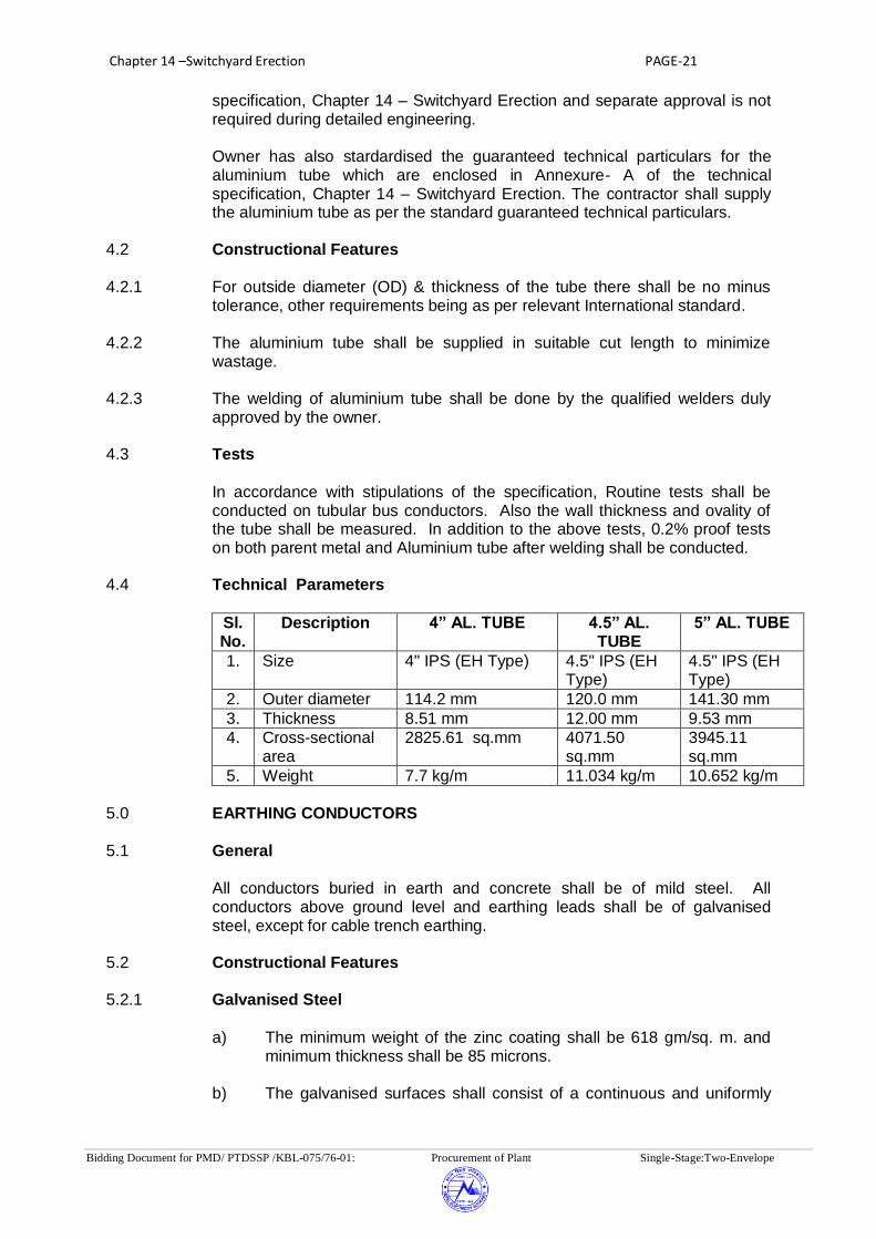
Chapter 14 –Switchyard Erection PAGE-21
Bidding Document for PMD/ PTDSSP /KBL-075/76-01: Procurement of Plant Single-Stage:Two-Envelope
specification, Chapter 14 – Switchyard Erection and separate approval is not required during detailed engineering.
Owner has also stardardised the guaranteed technical particulars for the aluminium tube which are enclosed in Annexure- A of the technical specification, Chapter 14 – Switchyard Erection. The contractor shall supply the aluminium tube as per the standard guaranteed technical particulars.
4.2 Constructional Features 4.2.1 For outside diameter (OD) & thickness of the tube there shall be no minus
tolerance, other requirements being as per relevant International standard. 4.2.2 The aluminium tube shall be supplied in suitable cut length to minimize
wastage. 4.2.3 The welding of aluminium tube shall be done by the qualified welders duly
approved by the owner. 4.3 Tests
In accordance with stipulations of the specification, Routine tests shall be
conducted on tubular bus conductors. Also the wall thickness and ovality of the tube shall be measured. In addition to the above tests, 0.2% proof tests on both parent metal and Aluminium tube after welding shall be conducted.
4.4 Technical Parameters
Sl. No.
Description 4” AL. TUBE 4.5” AL. TUBE
5” AL. TUBE
1. Size 4" IPS (EH Type) 4.5" IPS (EH Type)
4.5" IPS (EH Type)
2. Outer diameter 114.2 mm 120.0 mm 141.30 mm
3. Thickness 8.51 mm 12.00 mm 9.53 mm
4. Cross-sectional area
2825.61 sq.mm 4071.50 sq.mm
3945.11 sq.mm
5. Weight 7.7 kg/m 11.034 kg/m 10.652 kg/m
5.0 EARTHING CONDUCTORS
5.1 General
All conductors buried in earth and concrete shall be of mild steel. All
conductors above ground level and earthing leads shall be of galvanised steel, except for cable trench earthing.
5.2 Constructional Features
5.2.1 Galvanised Steel
a) The minimum weight of the zinc coating shall be 618 gm/sq. m. and
minimum thickness shall be 85 microns. b) The galvanised surfaces shall consist of a continuous and uniformly

Chapter 14 –Switchyard Erection PAGE-22
Bidding Document for PMD/ PTDSSP /KBL-075/76-01: Procurement of Plant Single-Stage:Two-Envelope
thick coating of zinc, firmly adhering to the surfaces of steel. The finished surface shall be clean and smooth and shall be free from defects like discoloured patches, bare spots, unevenness of coating, spelter which is loosely attached to the steel globules, spiky deposits, blistered surfaces, flaking or peeling off etc. The presence of any of these defects noticed on visual or microscopic inspection shall render the material liable to rejection.
5.3 Tests In accordance with stipulations of the specifications galvanised steel shall be
subjected to four one minute dips in copper sulphate solution as per relevant international standard.
6.0 SPACERS
6.1 General
The spacers are to be located at a suitable spacing to limit the short circuit
forces as per IEC -60865. Wherever Employer’s 220kV & 132kV standard gantry structures are being used, the spacer span(s) for different conductor / span configurations and corresponding short circuit forces shall be as per relevant IEC. For strung buses, flexible type spacers shall be used whereas for jumpers and other connections rigid type spacers shall be used.
Wherever Employer’s 400kV, 220kV & 132kV standard gantry structures are not being used, necessary spacer span calculation shall be provided by the contractor during detailed engineering for the approval of Employer.
6.2 Constructional Features 6.2.1 No magnetic material shall be used in the fabrication of spacers except for GI
bolts and nuts. 6.2.2 Spacer design shall be made to take care of fixing and removing during
installation and maintenance. 6.2.3 The design of the spacers shall be such that the conductor does not come in
cont with any sharp edge. 6.3 Tests Each type of spacers shall be subjected to the following type tests,
acceptance tests and routine tests: 6.3.1 Type Tests: Following type test reports shall be submitted for approval as per
clause 9.2 of Chapter 2 - GTR. a) Clamp slip tests
The sample shall be installed on test span of twin conductor bundle
string or quadruple conductor bundle string (as applicable) at a tension of 44.2 kN. One of the clamps of the sample when subjected to a longitudinal pull of 2.5 kN parallel to the axis of the conductor shall not slip on the conductor. The permanent displacement between the conductor and the clamp of sample measured after removal of the

Chapter 14 –Switchyard Erection PAGE-23
Bidding Document for PMD/ PTDSSP /KBL-075/76-01: Procurement of Plant Single-Stage:Two-Envelope
load shall not exceed 1.0 mm. Similar tests shall be performed on the other clamps of the same sample.
b) Fault current test. c) Corona Extinction Voltage Test (Dry). This test shall be performed on 400kV and 220 kV equipment as per
procedure mentioned at Chapter 2-GTR, Minimum Corona Extinction voltage shall be as per IEC.
d) RIV Test (Dry) This test shall be performed as per procedure mentioned at Chapter
2-GTR, Maximum RIV level at 305 kV (rms) line to ground and 156 kV (rms) line to ground for 400kV and 220 kV spacers respectively shall be 1000 micro volts, across 300 ohm resistor at 1 MHz
e) Resilience test (if applicable) f) Tension Test g) Log decremant test (if applicable) h) Compression test i) Galvanising test 6.3.2 Acceptance Test
a) Visual examination b) Dimensional verification c) Movement test d) Clamp slip test e) Clamp bolt torque test (if applicable) f) Assembly torque test g) Compression test h) Tension test i) Galvanising test j) Hardness test for neoprene (if applicable) The shore hardness of different points on the elastometer surface of
cushion grip clamp shall be measured by shore hardness meter. It shall be between 65 to 80.
k) Ultimate Tensile Strength Test The UTS of the retaining rods shall be measured. It shall not be less
than 35 kg/Sq. mm. 6.3.3 Routine test
a) Visual examination b) Dimensional verification 7.0 BUS POST INSULATORS The post insulators shall conform in general to latest IEC-60168, IEC 60273

Chapter 14 –Switchyard Erection PAGE-24
Bidding Document for PMD/ PTDSSP /KBL-075/76-01: Procurement of Plant Single-Stage:Two-Envelope
and IEC-60815. 7.1 Constructional Features
7.1.1 Post type insulators shall consist of a porcelain part permanently secured in a
metal base to be mounted on the supporting structures. They shall be capable of being mounted upright. They shall be designed to withstand any shocks to which they may be subjected to by the operation of the associated equipment. Only solid core insulators will be acceptable.
7.1.2 Porcelain used shall be homogeneous, free from lamination, cavities and
other flaws or imperfections that might affect the mechanical or dielectric quality and shall be thoroughly vitrified, tough and impervious to moisture.
7.1.3 Glazing of the porcelain shall be of uniform brown in colour, free from blisters,
burrs and other similar defects. 7.1.4 The insulator shall have alternate long and short sheds with aerodynamic
profile, The shed profile shall also meet the requirements of IEC-60815 for the specified pollution level.
7.1.5 When operating at normal rated voltage there shall be no electric discharge
between conductor and insulators which would cause corrosion or injury to conductors or insulators by the formation of substance produced by chemical ion.
7.1.6 The design of the insulators shall be such that stresses due to expansion and
contraction in any part of the insulator shall not lead to deterioration. 7.1.7 All ferrous parts shall be hot dip galvanised. The zinc used for galvanising
shall be grade Zn 99.95. The zinc coating shall be uniform, adherent, smooth, reasonably bright, continuous and free from imperfections such as flux ash, rust stains, bulky white deposits and blisters. The metal parts shall not produce any noise generating corona under the operating conditions.
7.1.8 a) Every bolt shall be provided with a steel washer under the nut so that
part of the threaded portion of the bolts is within the thickness of the parts bolted together.
b) Flat washer shall be circular of a diameter 2.5 times that of bolt and of
suitable thickness. Where bolt heads/nuts bear upon the beveled surfaces they shall be provided with square tapered washers of suitable thickness to afford a seating square with the axis of the bolt.
c) All bolts and nuts shall be of steel with well formed hexagonal heads
forged from the solid and shall be hot dip galvanised. The nuts shall be good fit on the bolts and two clear threads shall show through the nut when it has been finally tightened up.
7.1.9 Bidder shall make available data on all the essential features of design
including the method of assembly of shells and metals parts, number of shells per insulator, the manner in which mechanical stresses are transmitted through shells to adjacent parts, provision for meeting expansion stresses, results of corona and thermal shock tests, recommended working strength and any special design or arrangement employed to increase life under

Chapter 14 –Switchyard Erection PAGE-25
Bidding Document for PMD/ PTDSSP /KBL-075/76-01: Procurement of Plant Single-Stage:Two-Envelope
service conditions. 7.2 Tests
In accordance with the stipulations of the specification, the post insulators
shall be subject to type, acceptance, sample and routine tests as per IEC-60168.
7.2.1 In addition to acceptance/sample/routine tests as per IEC-60168, the
following tests shall also be carried out. a) Ultrasonic test as an acceptance test b) Soundness test, metallurgical tests and magnetic test on MCI caps
and pedestal tests as acceptance test. c) All hot dip galvanised components shall be subject to check for
uniformity of thickness and weight of zinc coating on sample basis. d) The bending test shall be carried out at 50% minimum failing load in
four directions as a routine test and at 100% minimum failing load in four directions as an acceptance test.
e) Acceptance norms for visual defects allowed at site and also at works
shall be agreed in the Quality plan. 7.2.2 In accordance with the stipulation of specification, the following type tests
reports of the post insulators shall be submitted for approval as per clause 9.2 of Chapter 2 - GTR.
a) Power frequency withstand test (dry & wet) b) Lightning impulse test (dry) c) Measurement of R.I.V (Dry) d) Corona extinction voltage test (Dry) . e) Test for deflection under load f) Test for mechanical strength. 7.3 Technical Parameters of Bus Post Insulators.
Sl. No.
Description 245 kV 400 kV
a) Type Solid Core
Solid Core
b) Voltage Class (kV) 245 420
c) Dry and wet one minute power frequency withstand voltage(kV rms)
460 680
d) Dry lightning impulse withstand Voltage (kVp)
+ 1050 +1425
e) Wet switching surge withstand voltage —- + 1050

Chapter 14 –Switchyard Erection PAGE-26
Bidding Document for PMD/ PTDSSP /KBL-075/76-01: Procurement of Plant Single-Stage:Two-Envelope
(kVp)
f) Max. radio interference voltage (in microvolts) at voltage of 508 kV (rms) , 305 kV (rms) and 156 (rms) for 765 kV, 400 kV &220 kV respectively between phase to ground.
500 500
g) Corona extinction voltage (kV rms) (min.)
156 320
h) Cantilever Strength
(i) Total minimum cantilever strength (Kg) 800 800
(ii) Total minimum breaking strength (Kg) 1000 1000
i) Minimum torsional moment As per IEC-273
As per IEC-273
j) Total height of insulator (mm) 2300 3650
k) P.C.D Top (mm) 127 127
Bottom (mm) 254 300
l) No. of bolts
Top 4 4
Bottom 8 8
m) Diameter of bolt/holes (mm)
Top M16 M16
Bottom dia 18 18
n) Pollution level as per IEC-815 Heavy(III) Heavy(III)
o) Minimum total creepage distance for Heavy Pollution (mm)
6125 10500
7.3.1 33kV Bus Post Insulators.
a) Type Solid Core b) Voltage class (kV) 36 c) Dry and wet one minute power 70 frequency withstand voltage(kV rms) d) Dry lightning impulse ±170 withstand Voltage (kVp) e) Total minimum cantilever 450 strength (Kg) f) Minimum torsional moment As per IEC-273 g) Total height of insulator (mm) As per requirement h) Pollution level as per Heavy(III) IEC-815 i) Minimum creepage distance for 900 Heavy Pollution (mm) 7.3.2 If corona extinction voltage is to be achieved with the help of corona ring or
any other similar device, the same shall be deemed to be included in the scope of the Contractor. Material of Corona ring shall be aluminium/aluminium alloy of 63401W grade or equivalent.

Chapter 14 –Switchyard Erection PAGE-27
Bidding Document for PMD/ PTDSSP /KBL-075/76-01: Procurement of Plant Single-Stage:Two-Envelope
8.0 GROUNDING SYSTEM 8.1 GENERAL
This specification covers the design, supply, delivery, installation and testing of the complete grounding system as described below. The complete station grounding work shall be in accordance with the recommendation in the "Guide for Safety in Substation Grounding" IEEE No. 80 and the requirements of this section.
8.2 GROUNDING INSTALLATION FEATURES
8.2.1 The installation shall be complete in all respects for efficient and trouble free service. All work shall be carried out in a first class neat workman like manner. Grounding conductors shall be handled carefully to avoid kinking and cutting of the conductors during laying and installation.All exposed ground conductors runs shall be taken in a neat manner, horizontal, vertical and parallel to building walls or columns and shall not be laid haphazardly.
8.2.2 For all connections made to equipment or to the structures, the grounding
conductor, connectors and equipment enclosures shall have good clean cont surfaces. Grounding conductor connection to all electrical equipment, switchgear, transformers, motors, panels, conduit system, equipment enclosures, cable trays, distribution boards, equipment frames, bases, steel structure, etc. shall be by pressure type or bolting type connectors.
8.2.3 All lap, cross and tee connections between two grounding conductors shall be
made by thermowelding process or compression type connector. The various joints shall have adequate mechanical strength as well as necessary electrical conductivity not less than that of the parent conductors of the joints. All accessories for grounding installation shall be of quality and design approved by the Employer. The earthing connection between earthing pad of equipment/structures shall be made by two earthing leads.
8.2.4 Ground conductors, when crossing underground trenches, directly laid
underground pipe and equipment foundation, if any, shall be at least 300mm below the bottom elevation of such trenches/pipes.
8.2.5 The maximum size of each grid of grounding mat shall not exceed 4X4
meters. The terminals for connecting ground mat and equipment shall be terminated whenever necessary. (The new grounding shall be bonded with existing grounding network.) at Dhalkebar and Hitauda Substations.
8.3 GROUNDING CONDUCTOR
8.3.1 Main Ground Grid The main ground system shall consist of a grounding grid buried minimum 0.6 meter below grade level. The grounding grid shall consist of copper flat conductor cable or stranded copper wire of minimum size (cross sectional area) 160sq. mm.
8.3.2 Ground Electrodes
The ground electrodes shall be 16mm diameter and 3.0 meter long (min.)

Chapter 14 –Switchyard Erection PAGE-28
Bidding Document for PMD/ PTDSSP /KBL-075/76-01: Procurement of Plant Single-Stage:Two-Envelope
copper clad steel. Theseshall be driven into ground and connected to the main ground grid.
8.3.3 Risers The risers shall consist of copper conductor of adequate size (but not less than 160 sq. mm.) connected at one end to the main ground mat and at the other end to the equipment.
8.4 DESIGN REQUIREMENTS
8.4.1 The Contractor shall measure the soil resistivity in presence of the Employer. Based on the resistivity the contractor shall calculate the total length of buried ground conductor, number of grounding electrode and their depth and spacing to achieve a grounding system resistance of less than 1.0 (One) Ohm.
8.4.2 The Contractor shall calculate the cross-section considering the maximum
fault level of 50 kA.
8.4.3 The Contractor shall submit the details of calculations of the grounding system for the Employer’s approval. The earthing system shall be of single earthing system for the whole substation i.e. all earthings shall be connected to main earthing grid.
8.5 TESTS
On completion of the installation, either wholly or in sections, it shall be tested in compliance with relevant Code by the Contractor in presence of the Employer. The cost of any test including labor, material and equipment charges shall be borne by the Contractor. If the ground grid resistance can not be obtained as per his design, then additional grounding conductors shall be buried in the earth, or if necessary, buried in treated soil to obtain the required low ground resistance without any additional cost.
8.6 LIGHTNING PROTECTION
The outdoor equipment of the substation and the substation building shall be protected against lightning. The lightning protection shall be achieved by an overhead lightning shield system of galvanized steel wire of 7/3.35 mm, which shall be connected to the main grounding grid by steel conductor of 7/3.35 mm. Lighting mast with electrode length of 2.5mtr (maximum) may be used in sqitchyard area for lighting protection as per requirement. The above electrode may be connected to the main grounding grid by steel conductor of 7/3.35 mm . The design of the lightning protection system shall be subject to the approval of the Employer.
8.7 DRAWINGS
After award of the Contract, the Contractor shall furnish the grounding layout drawing with dimensions showing the location of grounding grids, electrodes, test link chambers and risers, backed up by necessary calculations for Employer's approval. The work shall have to be started at site only after getting approval from the Employer. If alteration is required for any work done before getting Employer's approval, the same shall have to be done by the Contractor at no extra cost to the Employer.

Chapter 14 –Switchyard Erection PAGE-29
Bidding Document for PMD/ PTDSSP /KBL-075/76-01: Procurement of Plant Single-Stage:Two-Envelope
STATION GROUNDING SYSTEM
DESCRIPTION UNIT REQD
1. Main ground grid conductor material Copper
2. Main ground grid conductor size Sq.mm ≥ 160
3. Cross section of riser conductors Sq mm ≥ 160
4. Ground electrodes
-Material Copper clad steel
-Diameter mm ≥16
-Length meter 3
5. Material of risers Copper
6. Earthing system designed for ohm ≤ 1
9.0 Main Bus Bars (Applicable for Aluminium tube)
The brief description of the bus switching scheme, bus bar layout and
equipment connection to be adopted are indicated elsewhere in the specification. The bus bar arrangements are shown in drgs enclosed with the bid documents.
9.1 The Contractor shall furnish supporting calculations where applicable for the
bus bars/conductors to show adequacy of design parameters for: a) Fibre-stress b) Cantilever strength of post insulators c) Aeolain vibrations d) Vertical deflection of bus bars e) Short circuit forces in bundle conductor and spacer location for each
span of ACSR conductor stringing as per layout drawings. 9.1.1 The welds in the aluminium tubes shall be kept to the minimum and there
shall not be more than one weld per span. The procedure and details of welding shall be subject to Owner’s approval. Material for welding sleeve shall be same as that of Aluminium tube. Welding sleeve shall be of 600mm length
9.1.2 Corona bells shall be provided wherever the bus extends beyond the clamps
and on free ends, for sealing the ends of the tubular conductor against rain and moisture and to reduce the electrostatic discharge loss at the end points. There shall be a small drain hole in the corona bell. The material of Corona bell shall be Aluminium alloy similar to that of clamps & connectors.
9.1.3 To minimise the vibrations in the aluminium tubes, damping conductor shall
be provided inside the aluminium tubes. For this purpose, the cut pieces of ACSR conductor which otherwise are considered wastages, shall be used as damping conductor.

Chapter 14 –Switchyard Erection PAGE-30
Bidding Document for PMD/ PTDSSP /KBL-075/76-01: Procurement of Plant Single-Stage:Two-Envelope
9.1.4 Details of past experience of the persons proposed to be employed for
Aluminium tube welding and the test reports of the welded pieces to prove the electrical and mechanical chareristics shall also be furnished along with the bid. Welding at site shall be done by adopting a qualified procedure and employing qualified welders as per ASME-Section IX.
10.0 BAY EQUIPMENT
10.1 The disposition of various bay equipments shall be as per single line
diagrams and layout drawings. 10.2 Bay Marshalling Kiosk:- One no. of bay marshalling kiosk shall be provided for each 220 kV and 400
kV bay under present scope. In addition to the requirements specified elsewhere in the specification, the bay marshalling kiosk shall have two distinct compartments for the following purpose:-
(i) To receive two incoming 400V, 3 phase, 63Amps, AC supply with auto changeover and MCB unit and distribute minimum six outgoing 400V, 3 phase, 16 Amps AC supplies controlled by MCB.
(ii) To distribute minimum ten outgoing 230V, 10 Amps single phase supplies to be controlled by MCB to be drawn from above 3 phase incomers.
(iii) 200 nos. terminal blocks in vertical formation for interlocking facilities
for substations without automation system. (iv) Necessary Terminal Blocks for terminating cables from ACDB and
switchyard panel rooms. 11.0 EQUIPMENT ERECTION DETAILS
11.1 For equipment interconnection, the surfaces of equipment terminal pads,
Aluminium tube, conductor & terminal clamps and connectors shall be properly cleaned. After cleaning, cont grease shall be applied on the cont surfaces of equipment terminal pad, Aluminium tube/conductor and terminal clamps to avoid any air gap in between. Subsequently bolts of the terminal pad/terminal connectors shall be tightened and the surfaces shall be cleaned properly after equipment interconnection.
11.2 Muslin or leather cloth shall be used for cleaning the inside and outside of
hollow insulators. 11.3 All support insulators, circuit breaker interrupters and other fragile equipment
shall preferably be handled with cranes having suitable booms and handling capacity.

Chapter 14 –Switchyard Erection PAGE-31
Bidding Document for PMD/ PTDSSP /KBL-075/76-01: Procurement of Plant Single-Stage:Two-Envelope
11.4 Bending of Aluminium tube and compressed air piping if any should be done by a bending machine and through cold bending only. Bending shall be such that inner diameter of pipe is not reduced.
11.5 Cutting of the pipes wherever required shall be such as to avoid flaring of the
ends. Hence only a proper pipe cutting tool shall be used. Hack saw shall not be used.
11.6 Handling of equipment shall be done strictly as per manufacturer’s/supplier’s
instructions/instruction manual. 11.7 Handling equipment, sling ropes etc. should be tested periodically before
erection for strength. 11.8 The slings shall be of sufficient length to avoid any damage to insulator due to
excessive swing, scratching by sling ropes etc. 12.0 STORAGE
12.1 The Contractor shall provide and construct adequate storage shed for proper
storage of equipments, where sensitive equipments shall be stored indoors. All equipments during storage shall be protected against damage due to s of nature or accidents. The storage instructions of the equipment manufacturer/Owner shall be strictly adhered to.
13.0 CABLING MATERIAL 13.1 CABLE TAGS AND MARKERS
13.1.1 Each cable and conduit run shall be tagged with numbers that appear in the
cable and conduit schedule. 13.1.2 The tag shall be of aluminium with the number punched on it and securely
attached to the cable conduit by not less than two turns of 20 SWG GI wire. Cable tags shall be of rectangular shape for power cables and of circular shape for control cables.
13.1.3 Location of cables laid directly underground shall be clearly indicated with
cable marker made of galvanised iron plate. 13.1.4 Location of underground cable joints shall be indicated with cable marker with
an additional inscription “Cable joints”. 13.1.5 The marker shall project 150 mm above ground and shall be spaced at an
interval of 30 meters and at every change in direction. They shall be located on both sides of road and drain crossings.
13.1.6 Cable tags shall be provided on all cables at each end (just before entering
the equipment enclosure), on both sides of a wall or floor crossing, on each duct/conduit entry and at each end & turning point in cable tray/trench runs. Cable tags shall be provided inside the switchgear, motor control centres, control and relay panels etc., wherever required for cable identification, where a number of cables enter together through a gland plate.
13.2 Cable Supports and Cable Tray Mounting Arrangements

Chapter 14 –Switchyard Erection PAGE-32
Bidding Document for PMD/ PTDSSP /KBL-075/76-01: Procurement of Plant Single-Stage:Two-Envelope
13.2.1 The Contractor shall provide embedded steel inserts on concrete floors/walls
to secure supports by welding to these inserts or available building steel structures.
13.2.2 The supports shall be fabricated from standard structural steel members. 13.2.3 Insert plates will be provided at an interval of 750 mm wherever cables are to
be supported without the use of cable trays, such as in trenches, while at all other places these will be at an interval of 2000 mm.
13.2.4 Vertical run of cables on equipment support structure shall be supported on
perforated cable trays of suitable width which shall be suitably bolted/clamped with the equipment support structure.
. 13.3 Cable Termination and Connections 13.3.1 The termination and connection of cables shall be done strictly in accordance
with cable and termination kit manufacturer’s instructions, drawing and/or as directed by the Owner.
13.3.2 The work shall include all clamping, fittings, fixing, plumbing, soldering,
drilling, cutting, taping, heat shrinking (where applicable), connecting to cable terminal, shorting and grounding as required to complete the job.
13.3.3 Supply of all consumable material shall be in the scope of Contractor. 13.3.4 The equipment will be generally provided with undrilled gland plates for
cables/conduit entry. The Contractor shall be responsible for drilling of gland plates, painting and touching up. Holes shall not be made by gas cutting.
13.3.5 Control cable cores entering control panel/switchgear/MCCB/MCC/
miscellaneous panels shall be neatly bunched, clamped and tied with nylon strap or PVC perforated strap to keep them in position.
13.3.6 The Contractor shall tag/ferrule control cable cores at all terminations, as
instructed by the Owner. In panels where a large number of cables are to be terminated and cable identification may be difficult, each core ferrule may include the complete cable number as well.
13.3.7 Spare cores shall be similarly tagged with cable numbers and coiled up. 13.3.8 All cable entry points shall be sealed and made vermin and dust proof.
Unused openings shall be effectively closed. 13.3.9 Double compression type nickel plated (coating thickness not less than 10
microns) brass cable glands shall be provided by the Contractor for all power and control cables to provide dust and weather proof terminations.
13.3.10 They shall comprise of heavy duty brass casting, machine finished and nickel
plated, to avoid corrosion and oxidation. Rubber components used in cable glands shall be neoprene and of tested quality. Cable glands shall be of approved make.
13.3.11 The cable glands shall also be suitable for dust proof and weather proof
Chapter 14 –Switchyard Erection PAGE-33
Bidding Document for PMD/ PTDSSP /KBL-075/76-01: Procurement of Plant Single-Stage:Two-Envelope
termination. The test procedure, if required, has to be discussed and agreed to between Owner and cable gland manufacturer.
13.3.12 If the cable-end box or terminal enclosure provided on the equipment is found
unsuitable and requires modification, the same shall be carried out by the Contractor, as directed by the Owner.
13.3.13 Crimping tool used shall be of approved design and make. 13.3.14 Cable lugs shall be tinned copper solderless crimping type conforming to
relevant international standard. Bimetallic lugs shall be used depending upon type of cables used.
13.3.15 Solderless crimping of terminals shall be done by using corrosion inhibitory
compound. The cable lugs shall suit the type of terminals provided. 13.4 STORAGE AND HANDLING OF CABLE DRUMS
13.4.1 Cable drums shall be unloaded, handled and stored in an approved manner
and rolling of drums shall be avoided as far as possible. For short distances, the drums may be rolled provided they are rolled slowly and in proper direc-tion as marked on the drum.
14.0 DIRECTLY BURIED CABLES
14.1 The Contractor shall construct the cable trenches required for directly buried
cables. The scope of work shall include excavation, preparation of sand bedding, soil cover, supply and installation of brick or concrete protective covers, back filling and ramming, supply and installation of route markers and joint markers. The Bidder shall ascertain the soil conditions prevailing at site, before submitting the bid.
14.2 The cable (power and control) between LT station, control room and fire
lighting pump house shall be laid in the buried cable trenches. In addition to the above, for lighting purpose also, buried cable trench can be used in outdoor area.
14.3 Cable route and joint markers and RCC warning covers shall be provided
wherever required. The voltage grade of cables shall be engraved on the marker.
15.0 INSTALLATION OF CABLES
15.1 Cabling in the control room shall be done on ladder type cable trays for
vertical runs while cabling in switchyard area shall be done on angles in the trench.
15.2 All cables from bay cable trench to equipment’s including and all interpole
cables (both power and control) for all equipment, shall be laid in PVC pipes of minimum 50 mm nominal outside diameter which shall be buried in the ground at a depth of 250mm below finish formation level. Separate PVC pipes shall be laid for control and power cables. Cable pull boxes of adequate size shall be provided if required.
15.3 Cables shall be generally located adjoining the electrical equipment through

Chapter 14 –Switchyard Erection PAGE-34
Bidding Document for PMD/ PTDSSP /KBL-075/76-01: Procurement of Plant Single-Stage:Two-Envelope
the pipe insert embedded in the floor. In the case of equipments located away from cable trench either pipe inserts shall be embedded in the floor connect-ing the cable trench and the equipment or in case the distance is small, notch/opening on the wall shall be provided. In all these cases necessary bending radius as recommended by the cable manufacturer shall be maintained.
15.4 Cable racks and supports shall be painted after installation with two coats of
metal primer (comprising of red oxide and zinc chromate in a synthetic medium) followed by two finishing coats of aluminium paint.
15.5 Suitable arrangement should be used between fixed pipe / cable trays and equipment terminal boxes, where vibration is anticipated.
15.6 Power and control cables in the cable trench shall be laid in separate tiers.
The order of laying of various cables shall be as follows, for cables other than directly buried.
a) Power cables on top tiers. b) Control instrumentation and other service cables in bottom tiers. 15.7 Single core cables in trefoil formation shall be laid with a distance of three
times the diameter of cable between trefoil centre lines. All power cables shall be laid with a minimum centre to centre distance equal to twice the diameter of the cable of higher size of cables.
15.8 Trefoil clamps for single core cables shall be of pressure die cast aluminium
(LM-6), Nylon -6 or fibre glass and shall include necessary fixing GI nuts, bolts, washer etc. These are required at every 2 metre of cable runs.
15.9 Power and control cables shall be securely fixed to the trays/supports with
self locking type nylon ties with deinterlocking facility at every 5 metre interval for horizontal run. Vertical and inclined cable runs shall be secured with 25 mm wide and 2 mm thick aluminium strip clamps at every 2m.
15.10 Cables shall not be bent below the minimum permissible limit. The
permissible limits are as follows: Table of Cable and Minimum bending radius Power cable 12 D Control cable 10 D D is overall diameter of cable 15.11 Where cables cross roads, drains and rail tracks, these shall be laid in
reinforced spun concrete or steel pipes buried at not less than one metre depth.
15.12 In each cable run some extra length shall be kept at a suitable point to enable
one (for LT cables)/two (for H.T. cables) straight through joints to be made in case the cable develop fault at a later date.
15.13 Selection of cable drums for each run shall be so planned as to avoid using

Chapter 14 –Switchyard Erection PAGE-35
Bidding Document for PMD/ PTDSSP /KBL-075/76-01: Procurement of Plant Single-Stage:Two-Envelope
straight through joints. Cable splices will not be permitted except where called for by the drawings, unavoidable or where permitted by the Owner. If straight through joints are unavoidable, the Contractor shall use the straight through joints kit of reputed make.
15.14 Control cable terminations inside equipment enclosures shall have sufficient
lengths so that changing of termination in terminal blocks can be done without requiring any splicing.
15.15 Metal screen and armour of the cable shall be bonded to the earthing system
of the station, wherever required by the Owner. 15.16 Rollers shall be used at intervals of about two metres while pulling cables. 15.17 All due care shall be taken during unreeling, laying and termination of cable to
avoid damage due to twist, kinks, sharp bends, etc. 15.18 Cable ends shall be kept sealed to prevent damage. In cable vault, fire
resistant seal shall be provided underneath the panels. 15.19 Inspection on receipt, unloading and handling of cables shall generally be in
accordance with relevant international standard. 15.20 Wherever cable pass through floor or through wall openings or other
partitions, GI/PVC wall sleeves with bushes having a smooth curved internal surface so as not to damage the cable, shall be supplied, installed and properly sealed by the Contractor at no extra charges.
15.21 Contractor shall remove the RCC/Steel trench covers before taking up the
work and shall replace all the trench covers after the erection-work in that particular area is completed or when further work is not likely to be taken up for some time.
15.22 Contractor shall furnish three copies of the report on work carried out in a
particular week, indicating cable numbers, date on which laid, ual length and route, testing carried out, terminations carried out, along with the marked up copy of the cable schedule and interconnection drawing wherever any modifications are made.
15.23 Contractor shall paint the tray identification number on each run of trays at an
interval of 10 m. 15.24 In case the outer sheath of a cable is damaged during handling/installation,
the Contractor shall repair it at his own cost to the satisfaction of the Owner. In case any other part of a cable is damaged, the same shall be replaced by a healthy cable at no extra cost to the Owner, i.e. the Contractor shall not be paid for installation and removal of the damaged cable.
15.25 All cable terminations shall be appropriately tightened to ensure secure and
reliable connections. The Contractor shall cover the exposed part of all cable lugs whether supplied by him or not with insulating tape, sleeve or paint.
15.26 Cable trays
i) The cable trays shall be of G.S.sheet and minimum thickness of sheet

Chapter 14 –Switchyard Erection PAGE-36
Bidding Document for PMD/ PTDSSP /KBL-075/76-01: Procurement of Plant Single-Stage:Two-Envelope
shall be 2mm. ii) The Contractor shall perform all tests and inspection to ensure that
material and workmanship are according to the relevant standards. A 2.5 metre straight section of 300mm, 600mm wide cable tray shall be
simply supported at two ends. A uniform distributed load of 76 kg/m shall be applied along the length of the tray. The maximum deflection at the mid-span shall not exceed 7mm.
15.27 Conduits, Pipes and Duct Installation
15.27.1 Contractor shall supply and install all rigid conduits, mild steel pipes,flexible
conduits, hume pipes etc. including all necessary sundry materials such as tees, elbows, check nuts, bushing, reducers, enlargers, coupling cap, nipples, gland sealing fittings, pull boxes etc as specified and to be shown in detailed drawing. The size of the conduit/pipe shall be selected on the basis of 40% fill criterion.
15.27.2 Contractor shall have his own facility for bending, cutting and threading the
conduits at site. Cold bending should be used. All cuts & threaded ends shall be made smooth without leaving any sharp edges. Anticorrosive paint shall be applied at all field threaded portions.
15.27.3 All conduit/pipes shall be extended on both sides of wall/floor openings. The
fabrication and installation of supports and the clamping shall be included in the scope of work by Contractor.
15.27.4 When two lengths of conduits are joined together through a coupling, running
threads equal to twice the length of coupling shall be provided on each conduit to facilitate easy dismantling of two conduits.
15.27.5 Conduit installation shall be permanently connected to earth by means of
special approved type of earthing clamps. GI pull wire of adequate size shall be laid in all conduits before installation.
15.27.6 Each conduit run shall be painted with its designation as indicated on the
drawings such that it can be identified at each end. 15.27.7 Embedded conduits shall have a minimum concrete cover of 50 mm. 15.27.8 Conduit run sleeves shall be provided with the bushings at each end. 15.27.9 Metallic conduit runs at termination shall have two locknuts and a bushing for
connection. Flexible conduits shall also be suitably clamped at each end with the help of bushings. Bushings shall have rounded edges so as not to damage the cables.
15.27.10 Where embedded conduits turn upwards from a slab or fill, the termination
dimensions shown on the drawings, if any, shall be taken to represent the position of the straight extension of the conduit external to and immediately following the bend. At least one half of the arc length of the bend shall be embedded.
15.27.11 All conduits/pipes shall have their ends closed by caps until cables are pulled.

Chapter 14 –Switchyard Erection PAGE-37
Bidding Document for PMD/ PTDSSP /KBL-075/76-01: Procurement of Plant Single-Stage:Two-Envelope
After cables are pulled, the ends of conduits/pipes shall be sealed in an approved manner to prevent damage to threaded portions and entrance of moisture and foreign material.
15.27.12 For underground runs, Contractor shall excavate and back fill as necessary. 15.27.13 Contractor shall supply, unload, store and install conduits required for the
lighting installation as specified. All accessories/fittings required for making the installation complete, including but not limited to pull out boxes, ordinary and inspection tees and elbow, checknuts, male and female bushings (brass or galvanised steel), caps, square headed male plugs, nipples, gland sealing fittings ,pull boxes, conduits terminal boxes, gaskets and box covers, saddle terminal boxes, and all steel supporting work shall be supplied by the Contractor. The conduit fittings shall be of the same material as conduits.
15.27.14 All unarmoured cables shall run within the conduits from lighting panels to
lighting fixtures, receptacles etc. 15.27.15 Size of conduit for lighting shall be selected by the Contractor during detailed
engineering. 15.27.16 Exposed conduits shall be run in straight lines parallel to building columns,
beams and walls. Unnecessary bends and crossings shall be avoided to present a neat appearance.
15.27.17 Conduit supports shall be provided at an interval of 750mm for horizontal runs
and 1000mm for vertical runs. 15.27.18 Conduit supports shall be clamped on the approved type spacer plates or
brackets by saddles or U- bolts. The spacer plates or brackets in turn, shall be securely fixed to the building steel by welding and to concrete or brick work by grouting or by nylon rawl plugs. Wooden plug inserted in the masonary or concrete for conduit support is not acceptable.
15.27.19 Embedded conduits shall be securely fixed in position to preclude any
movement. In fixing embedded conduit, if welding or brazing is used, extreme care should be taken to avoid any injury to the inner surface of the conduit.
15.27.20 Spacing of embedded conduits shall be such as to permit flow of concrete
between them. 15.27.21 Where conduits are placed alongwith cable trays, they shall be clamped to
supporting steel at an interval of 600mm. 15.27.22 For directly embedding in soil, the conduits shall be coated with an asphalt-
base compound. Concrete pier or anchor shall be provided wherever necessary to support the conduit rigidly and to hold it in place.
15.27.23 Conduit shall be installed in such a way as to ensure against trouble from
trapped condensation. 15.27.24 Conduits shall be kept, wherever possible, at least 300mm away from hot
pipes, heating devices etc. when it is evident that such proximity may reduce the service life of cables.

Chapter 14 –Switchyard Erection PAGE-38
Bidding Document for PMD/ PTDSSP /KBL-075/76-01: Procurement of Plant Single-Stage:Two-Envelope
15.27.25 Slip joints shall be provided when conduits cross structural expansion joints or
where long run of exposed conduits are installed, so that temperature change will cause no distortion due to expansion or contrion of conduit run.
15.27.26 For long conduit run, pull boxes shall be provided at suitable intervals to
facilitate wiring. 15.27.27 Conduit shall be securely fastened to junction boxes or cabinets, each with a
lock nut inside and outside the box. 15.27.28 Conduits joints and connections shall be made thoroughly water-tight and rust
proof by application of a thread compound which insulates the joints. White lead is suitable for application on embedded conduit and red lead for exposed conduit.
15.27.29 Field bends shall have a minimum radius of four (4) times the conduit
diameter. All bends shall be free of kinks, indentations of flattened surfaces. Heat shall not be applied in making any conduit bend. Separate bends may be used for this purpose.
15.27.30 The entire metallic conduit system, whether embedded or exposed, shall be
electrically continuous and thoroughly grounded. Where slip joints are used, suitable bounding shall be provided around the joint to ensure a continuous ground circuit.
15.27.31 After installation, the conduits shall be thoroughly cleaned by compressed air
before pulling in the wire. 15.27.32 Lighting fixtures shall not be suspended directly from the junction box in the
main conduit run. 16.0 JUNCTION BOX a) The Contractor shall supply and install junction boxes complete with
terminals as required. The brackets, bolts, nuts, screws etc required for erection are also included in the scope of the Contractor.
b) Junction boxes having volume less than 1600 cubic centimeters may
be installed without any support other than that resulting from connecting conduits where two or more rigid metallic conduits enter and accurately position the box. Boxes shall be installed so that they are level, plumb and properly aligned to present a pleasing appearance.
c) Boxes with volumes equal to or greater than 1600 cubic cm, and
smaller boxes terminating on less than two rigid metallic conduits or for other reasons not rigidly held, shall be adequately supported by auxiliary steel of standard steel shapes or plates to be fabricated and installed. The Contractor shall perform all drilling, cutting, welding, shimming and bolting required for attachment of supports.
17.0 TESTING AND COMMISSIONING 17.1 An indicative list of tests for testing and commissioning is given below.
Chapter 14 –Switchyard Erection PAGE-39
Bidding Document for PMD/ PTDSSP /KBL-075/76-01: Procurement of Plant Single-Stage:Two-Envelope
Contractor shall perform any additional test based on specialities of the items as per the field Q.P./instructions of the equipment Contractor or Owner without any extra cost to the Owner. The Contractor shall arrange all equipments instruments and auxiliaries required for testing and commissioning of equipments alongwith calibration certificates and shall furnish the list of instruments to the Owner for approval.
17.2 GENERAL CHECKS
(a) Check for physical damage. (b) Visual examination of zinc coating/plating. (c) Check from name plate that all items are as per order/specification. (d) Check tightness of all bolts, clamps and connecting terminals using
torque wrenches. (e) For oil filled equipment, check for oil leakage, if any. Also check oil
level and top up wherever necessary. (f) Check ground connections for quality of weld and application of zinc
rich paint over weld joint of galvanised surfaces. (g) Check cleanliness of insulator and bushings. (h) All checks and tests specified by the manufacturers in their drawings
and manuals as well as all tests specified in the relevant code of erection.
(i) Check for surface finish of grading rings (Corona control ring). (j) Pressure test on all pneumatic lines at 18.5 times the rated pressure
shall be conducted. 17.3 STATION EARTHING a) Check soil resistivity b) Check continuity of grid wires c) Check earth resistance of the entire grid as well as various sections of
the same. d) Check for weld joint and application of zinc rich paint on galvanised
surfaces. e) Dip test on earth conductor prior to use. 17.4 AAC/ACSR STRINGING WORK, TUBULAR BUS WORK AND POWER
CONNECTORS
a) Physical check for finish b) Electrical clearance check

Chapter 14 –Switchyard Erection PAGE-40
Bidding Document for PMD/ PTDSSP /KBL-075/76-01: Procurement of Plant Single-Stage:Two-Envelope
c) Testing of torque by torque wrenches on all bus bar power connectors
and other accessories. d) Millivolt drop test on all power connectors. e) Sag and tension check on conductors. 17.5 ALUMINIUM TUBE WELDING a) Physical check b) Millivolt drop test on all joints. c) Dye penetration test & Radiography test on 10% sample basis on
weld joints.
c) Test check on 5% sample joints after cutting the weld piece to observe any voids etc.
17.6 INSULATOR
Visual examination for finish, damage, creepage distance etc. 17.7 All pre/commissioning invitees and works for substation equipment shall be
carried out in accordance with owner's ''Pre- Commissioning procedures and formats for substation bay equipments" by the contractor. This document shall be provided to the successful contractor during detailed engineering stage.
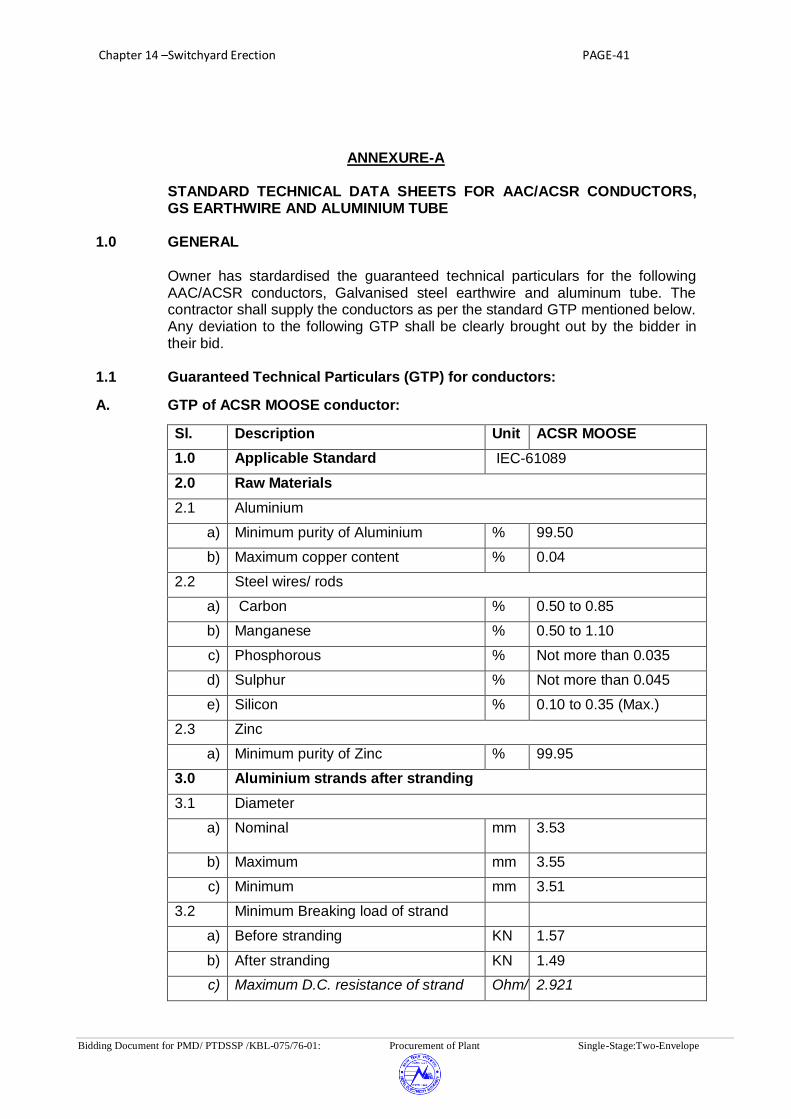
Chapter 14 –Switchyard Erection PAGE-41
Bidding Document for PMD/ PTDSSP /KBL-075/76-01: Procurement of Plant Single-Stage:Two-Envelope
ANNEXURE-A STANDARD TECHNICAL DATA SHEETS FOR AAC/ACSR CONDUCTORS, GS EARTHWIRE AND ALUMINIUM TUBE
1.0 GENERAL
Owner has stardardised the guaranteed technical particulars for the following AAC/ACSR conductors, Galvanised steel earthwire and aluminum tube. The contractor shall supply the conductors as per the standard GTP mentioned below. Any deviation to the following GTP shall be clearly brought out by the bidder in their bid.
1.1 Guaranteed Technical Particulars (GTP) for conductors:
A. GTP of ACSR MOOSE conductor:
Sl. Description Unit ACSR MOOSE
1.0 Applicable Standard IEC-61089
2.0 Raw Materials
2.1 Aluminium
a) Minimum purity of Aluminium % 99.50
b) Maximum copper content % 0.04
2.2 Steel wires/ rods
a) Carbon % 0.50 to 0.85
b) Manganese % 0.50 to 1.10
c) Phosphorous % Not more than 0.035
d) Sulphur % Not more than 0.045
e) Silicon % 0.10 to 0.35 (Max.)
2.3 Zinc
a) Minimum purity of Zinc % 99.95
3.0 Aluminium strands after stranding
3.1 Diameter
a)
Nominal mm 3.53
b) Maximum mm 3.55
c) Minimum mm 3.51
3.2 Minimum Breaking load of strand
a) Before stranding KN 1.57
b) After stranding KN 1.49
c) Maximum D.C. resistance of strand Ohm/ 2.921

Chapter 14 –Switchyard Erection PAGE-42
Bidding Document for PMD/ PTDSSP /KBL-075/76-01: Procurement of Plant Single-Stage:Two-Envelope
Sl. Description Unit ACSR MOOSE
1.0 Applicable Standard IEC-61089
2.0 Raw Materials
2.1 Aluminium
at 20 deg. Centigrade KM
3.3 Maximum resistance of 1 m length of strand at 20 deg. C
Ohm 0.002921
4.0 Steel strand after stranding
4.1 Diameter
a) Nominal mm 3.53
b) Maximum mm 3.60
c) Minimum mm 3.46
4.2 Minimum Breaking load of strand
a) Before stranding KN 12.86
b) After stranding KN 12.22
4.3 Galvanising
a) Minimum weight of zinc coating per sq.m.
gm 260
b) Minimum number of dips that the galvanised strand can withstand in the standard preece test
Nos. 2 dips of one minute & 1 dip of half minute
c) Min. No. of twists in guage length equal 100 times the dia. of wire which the strand can withstand in the torsion test (after stranding)
Nos 16 (After stranding) 18 (Before stranding)
5.0 ACSR Conductor
5.1.a) Stranding Al -54/3.53 mm+ Steel-7/3.53 mm
b) Number of Strands
i. Steel centre Nos. 1
ii. 1st Steel Layer Nos. 6
iii. 1st Aluminium Layer Nos. 12
iv. 2nd Aluminium Layer Nos. 18
v. 3rd Aluminium Layer Nos. 24
5.2 Sectional Area of aluminium Sq. mm
528.50
5.3 Total sectional area Sq. mm
597.00
5.4 Approximate Weight Kg/m 2.004
5.5 Diameter of the conductor mm 31.77
5.6 UTS of the conductor kN 161.20 (Min.)
5.7 Lay ratio of the conductor mm Max Min
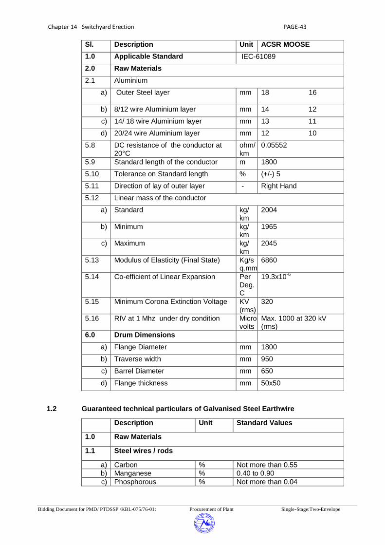
Chapter 14 –Switchyard Erection PAGE-43
Bidding Document for PMD/ PTDSSP /KBL-075/76-01: Procurement of Plant Single-Stage:Two-Envelope
Sl. Description Unit ACSR MOOSE
1.0 Applicable Standard IEC-61089
2.0 Raw Materials
2.1 Aluminium
a)
Outer Steel layer mm 18 16
b) 8/12 wire Aluminium layer mm 14 12
c) 14/ 18 wire Aluminium layer mm 13 11
d) 20/24 wire Aluminium layer mm 12 10
5.8 DC resistance of the conductor at 20°C
ohm/ km
0.05552
5.9 Standard length of the conductor m 1800
5.10 Tolerance on Standard length % (+/-) 5
5.11 Direction of lay of outer layer - Right Hand
5.12 Linear mass of the conductor
a) Standard kg/ km
2004
b) Minimum kg/ km
1965
c) Maximum kg/ km
2045
5.13 Modulus of Elasticity (Final State) Kg/sq.mm
6860
5.14 Co-efficient of Linear Expansion Per Deg. C
19.3x10⁻⁶
5.15 Minimum Corona Extinction Voltage KV (rms)
320
5.16 RIV at 1 Mhz under dry condition Microvolts
Max. 1000 at 320 kV (rms)
6.0 Drum Dimensions
a) Flange Diameter mm 1800
b) Traverse width mm 950
c) Barrel Diameter mm 650
d) Flange thickness mm 50x50
1.2 Guaranteed technical particulars of Galvanised Steel Earthwire
Sl. no. Description Unit Standard Values
1.0 Raw Materials
1.1 Steel wires / rods
a) Carbon % Not more than 0.55
b) Manganese % 0.40 to 0.90
c) Phosphorous % Not more than 0.04

Chapter 14 –Switchyard Erection PAGE-44
Bidding Document for PMD/ PTDSSP /KBL-075/76-01: Procurement of Plant Single-Stage:Two-Envelope
d) Sulphur % Not more than 0.04
e) Silicon % 0.15 to 0.35
1.2 Zinc
a) Minimum purity of Zinc % 99.95
2.0 Steel strands
2.1 Diameter
a) Nominal mm 3.66
b) Maximum mm 3.74
c) Minimum mm 3.58
2.2. Minimum breaking load of strand
a) After stranding KN 10.58
2.3 Galvanising
a) Minimum weight of zinc coating per sq.m. after stranding
gms. 275
b) Minimum number of dips that the galvanized strand can withstand in the standard preece test
Nos. 3 dips of 1 minute and one dip of
½ minute
c) Minimum number of twists in a gauge length equal to 100 times diameter of wire which the strand can withstand in the torsion test, after stranding
Nos. 18
3.0 Stranded Earth wire
3.1 UTS of Earth wire KN 68.4 (min.)
3.2 Lay length of outer steel layer
a) Standard mm 181
b) Maximum mm 198
c) Minimum mm 165
3.3 Maximum DC resistance of earth wire at 200 C
Ohm/km 3.375
3.4 Standard length of earth wire
M 2000 or ual quantity whichever is less.
3.5 Tolerance on standard length
% ±5
3.6 Direction of lay for outside layer
Right hand
3.7 Linear mass
a) Standard Kg/km 583
b) Maximum Kg/km 552
c) Minimum Kg/km 600
3.8 Overall diameter mm 10.98
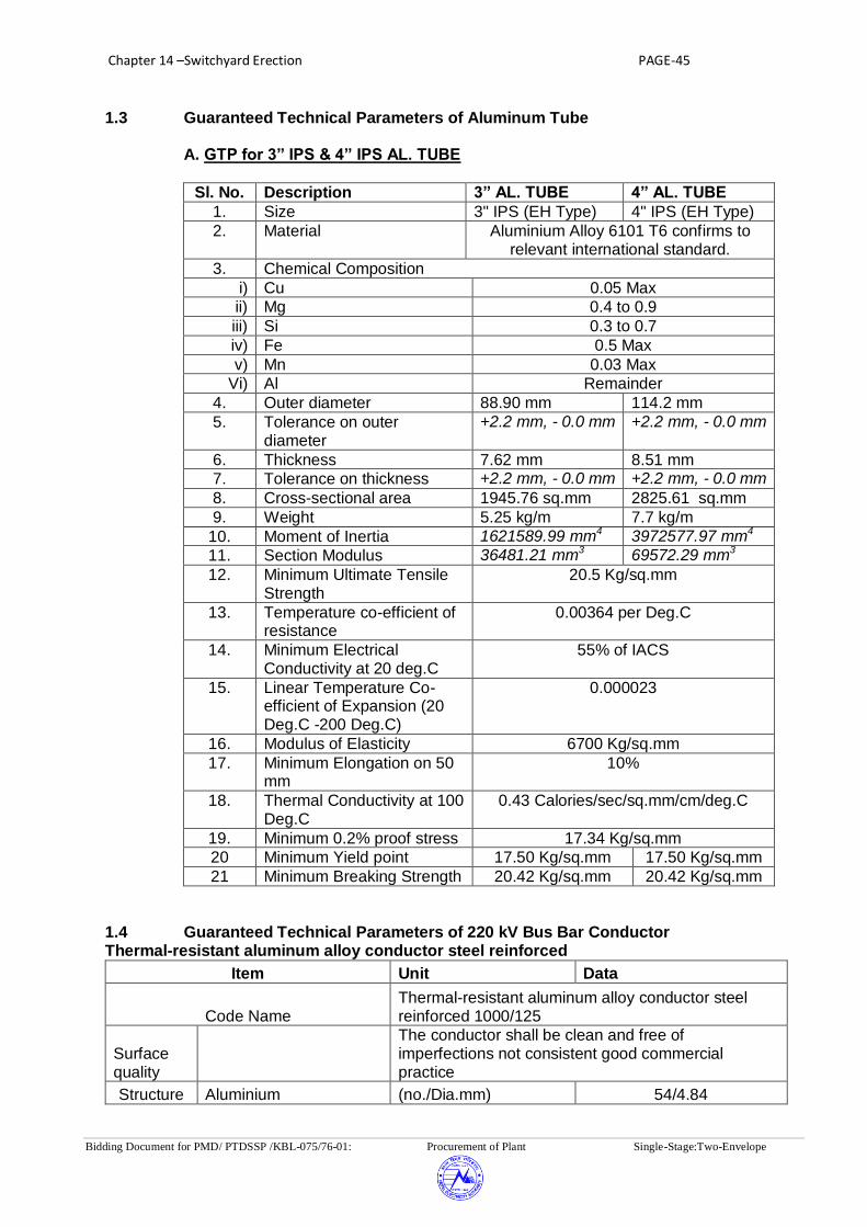
Chapter 14 –Switchyard Erection PAGE-45
Bidding Document for PMD/ PTDSSP /KBL-075/76-01: Procurement of Plant Single-Stage:Two-Envelope
1.3 Guaranteed Technical Parameters of Aluminum Tube A. GTP for 3” IPS & 4” IPS AL. TUBE
Sl. No. Description 3” AL. TUBE 4” AL. TUBE
1. Size 3" IPS (EH Type) 4" IPS (EH Type)
2. Material Aluminium Alloy 6101 T6 confirms to relevant international standard.
3. Chemical Composition
i) Cu 0.05 Max
ii) Mg 0.4 to 0.9
iii) Si 0.3 to 0.7
iv) Fe 0.5 Max
v) Mn 0.03 Max
Vi) Al Remainder
4. Outer diameter 88.90 mm 114.2 mm
5. Tolerance on outer diameter
+2.2 mm, - 0.0 mm +2.2 mm, - 0.0 mm
6. Thickness 7.62 mm 8.51 mm
7. Tolerance on thickness +2.2 mm, - 0.0 mm +2.2 mm, - 0.0 mm
8. Cross-sectional area 1945.76 sq.mm 2825.61 sq.mm
9. Weight 5.25 kg/m 7.7 kg/m
10. Moment of Inertia 1621589.99 mm4 3972577.97 mm4
11. Section Modulus 36481.21 mm3 69572.29 mm3
12. Minimum Ultimate Tensile Strength
20.5 Kg/sq.mm
13. Temperature co-efficient of resistance
0.00364 per Deg.C
14. Minimum Electrical Conductivity at 20 deg.C
55% of IACS
15. Linear Temperature Co-efficient of Expansion (20 Deg.C -200 Deg.C)
0.000023
16. Modulus of Elasticity 6700 Kg/sq.mm
17. Minimum Elongation on 50 mm
10%
18. Thermal Conductivity at 100 Deg.C
0.43 Calories/sec/sq.mm/cm/deg.C
19. Minimum 0.2% proof stress 17.34 Kg/sq.mm
20 Minimum Yield point 17.50 Kg/sq.mm 17.50 Kg/sq.mm
21 Minimum Breaking Strength 20.42 Kg/sq.mm 20.42 Kg/sq.mm
1.4 Guaranteed Technical Parameters of 220 kV Bus Bar Conductor Thermal-resistant aluminum alloy conductor steel reinforced
Item Unit Data
Code Name Thermal-resistant aluminum alloy conductor steel reinforced 1000/125
Surface quality
The conductor shall be clean and free of imperfections not consistent good commercial practice
Structure Aluminium (no./Dia.mm) 54/4.84
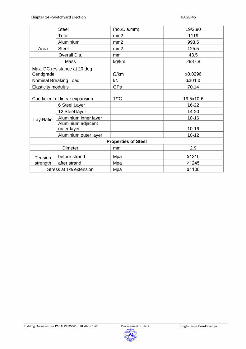
Chapter 14 –Switchyard Erection PAGE-46
Bidding Document for PMD/ PTDSSP /KBL-075/76-01: Procurement of Plant Single-Stage:Two-Envelope
Steel (no./Dia.mm) 19/2.90
Area
Total mm2 1119
Aluminium mm2 993.5
Steel mm2 125.5
Overall Dia. mm 43.5
Mass kg/km 2987.8
Max. DC resistance at 20 deg Centigrade Ω/km ≤0.0296
Nominal Breaking Load kN ≥301.0
Elasticity modulus GPa 70.14
Coefficient of linear expansion 1/°C 19.5x10⁻⁶
Lay Ratio
6 Steel Layer 16-22
12 Steel layer 14-20
Aluminium inner layer 10-16
Aluminium adjacent outer layer 10-16
Aluminium outer layer 10-12
Properties of Steel
Dimeter mm 2.9
Tension strength
before strand Mpa ≥1310
after strand Mpa ≥1245
Stress at 1% extension Mpa ≥1100

Chapter 14 –Switchyard Erection PAGE-47
Bidding Document for PMD/ PTDSSP /KBL-075/76-01: Procurement of Plant Single-Stage:Two-Envelope
ANNEXURE – B
A. SHORT CIRCUIT FORCES AND SPACER SPAN FOR 400kV GANTRY
STRUCTURE
Sl. Max. Span Conductor Ph-Ph Normal SCF per Spacer
No. Configuration Spacing Tension Phase span
I. For Fault Level of 40 kA for 1 sec.
1. 54 mtr QUAD ACSR 7 mtr 4 T 5.64 T 6 mtr
2. 70 mtr TWIN ACSR 7 mtr 4 T 5.64 T 5 mtr
3. 54 mtr QUAD ACSR 6 mtr 4 T 5.10 T 5 mtr
4. 70 mtr TWIN ACSR 6 mtr 4 T 5.10 T 5 mtr
5. 48 mtr QUAD ACSR 6 mtr 4 T 4.82T 5 mtr
6. 52.5 mtr QUAD ACSR 6 mtr 4 T 4.85T 5 mtr
7. 56.5 mtr QUAD ACSR 6 mtr 4 T 4.88T 5 mtr
8. 52.5 mtr TWIN ACSR 6 mtr 4 T 4.97T 5 mtr
9. 56.5 mtr TWIN ACSR 6 mtr 4 T 5.00 T 5 mtr
II. For Fault Level of 50 kA for 1 sec.
1. 48 mtr QUAD AAC
BULL 6 mtr 4 T 5.10 T 4 mtr
2. 52.5 mtr QUAD ACSR 6 mtr 4 T 5.18 T 4 mtr
3. 56.5 mtr QUAD ACSR 6 mtr 4 T 5.20 T 4 mtr
III. For Fault Level of 63 kA for 1 sec.
1. 48 mtr QUAD AAC
BULL 6 mtr 4 T 6.00 T 4 mtr
2. 52.5 mtr QUAD ACSR 6 mtr 4 T 6.33 T 4 mtr
3. 56.5 mtr QUAD ACSR 6 mtr 4 T 6.37 T 4 mtr

Chapter 14 –Switchyard Erection PAGE-48
Bidding Document for PMD/ PTDSSP /KBL-075/76-01: Procurement of Plant Single-Stage:Two-Envelope
B. SHORT CIRCUIT FORCES AND SPACER SPAN FOR 220 kV GANTRY
STRUCTURE
Sl. Max. Span Conductor Ph-Ph Normal SCF per Spacer
No. Configuration Spacing Tension Phase span
I.
For Fault Level of 40 kA for 1
sec.
1. 54 mtr QUAD ACSR 4.5 mtr 4 T 5.00 T 2.5 mtr
2. 54 mtr TWIN ACSR 4.5 mtr 2 T 3.50 T 2.5 mtr
3. 74 mtr TWIN ACSR 4.5 mtr 4 T 5.00 T 2.5 mtr
4. 54 mtr QUAD ACSR 4.0 mtr 4 T 5.70 T 2.5 mtr
5. 54 mtr TWIN ACSR 4.0 mtr 2 T 3.50 T 2.5 mtr
6. 74 mtr TWIN ACSR 4.0 mtr 4 T 5.70 T 2.5 mtr
7. 48 mtr QUAD ACSR 4.0 mtr 4 T 5.30 T 2.5 mtr
8. 52 mtr QUAD ACSR 4.0 mtr 4 T 5.35 T 2.5 mtr
9. 68 mtr TWIN ACSR 4.0 mtr 4 T 5.20 T 2.5 mtr
10. 56 mtr QUAD ACSR 4.0 mtr 4 T 5.50 T 2.5 mtr
11. 72 mtr TWIN ACSR 4.0 mtr 4 T 5.27 T 2.5 mtr
II.
For Fault Level of 50 kA for 1
sec.
1. 48 mtr QUAD ACSR 4.0 mtr 4 T 5.41 T 2.0 mtr
2. 52 mtr QUAD ACSR 4.0 mtr 4 T 5.50 T 2.0 mtr
3. 36 mtr TWIN ACSR 4.0 mtr 2 T 3.50 T 2.0 mtr
NOTE: ACSR conductor as mentioned above indicates that it is suitable for both ACSR MOOSE as well as ACSR BERSIMIS conductor.
C. SHORT CIRCUIT FORCES AND SPACER SPAN FOR 132 kV GANTRY
STRUCTURE
Sl. Max. Span Conductor Ph-Ph Normal SCF per Spacer
No. Configuration Spacing Tension Phase span
I.
For Fault Level of 31.5kA for 1
sec.
1. 36 mtr Twin Moose/ 3 mtr 1 T 2.15 T 2.5 mtr Zebra ACSR
2. 31.5 mtr Twin Moose/ 2.7mtr 1 T 2.15 T 2.5 mtr Zebra ACSR
3. 48 mtr Single Moose/ 3 mtr 1 T 2.05 T NA
Zebra ACSR
4. 42 mtr Single Moose/ 2.7 mtr 1 T 2.03 T NA
Zebra ACSR

Chapter 15 –Structure PAGE-1
Bidding Document for PMD/PTDSSP/KBL-075/76-01: Procurement of Plant Single-Stage:Two-Envelope
CHAPTER 15: STRUCTURE 1.0 GENERAL
The scope of specification covers design, fabrication, trial assembly, supply and erection of galvanized steel structures for Towers, Column, girders, lightning masts and equipment support structures. Structures shall be lattice or Pipe type structure fabricated from structural steel conforming to relevant British standard Codes (BS Codes)/ Indian Standard Codes (IS Codes)/equivalent International Standards.
The line diagram of all structures of 400kV, 220 kV, 132kV and 33 kV for
switch yards shall be prepared by the contractor based on their design during detailed engineering stage. The fabrication drawing/line diagram of structures for extension of existing switch yards shall be furnished by NEA to the successful bidder progressively during detailed engineering stage. The bidder shall mention in their bid for the type of proposed structure i.e. Pipe or lattice type structure. The fabrication drawings, proto corrected drawings along with Bill of Material (BOM) for all the structures (Both Gantry and Equipment support structures) shall be prepared by the contractor during detailed engineering for submission to NEA for their approval. Support structure for circuit breaker shall also be designed by the Manufacturer/Contractor.
It is the intent of the NEA to provide structures which allow
interchangeability of equipments at a later stage. Accordingly, Contractor is expected to design the equipment support structures with the provision of stool. Stools shall be provided by the Contractor between the equipment and its support structure to match the bus bar height. The top of stool shall be connected to the equipment and the bottom of the stool shall be connected to the Base support structure.
The scope shall include supply and erection of all types of structures
including bolts, nuts, washers, step bolts, inserts in concrete, gusset plates, equipment mounting bolts, structure earthing bolts, foundation bolts, spring washers, fixing plates, ground mounted marshalling boxes (AC/DC Marshalling box & equipment control cabinets), structure mounted marshalling boxes and any other items as required to complete the job.
The connection of all structures to their foundations shall be with base
plates and embedded anchor/foundation bolts. All steel structures and anchor/foundation bolts, fasteners (Nuts, bolts, washers) shall be fully galvanized as per relevant British standard Codes (BS Codes) / equivalent International Standards. The weight of the zinc coating shall be at least 610 grammes /sq. m for anchor bolts/foundation bolts and for structural members. One additional nut shall be provided below the base plate which may be used for the purpose of leveling.
Contractor shall provide suitable arrangement on the equipment support
structures wherever required to suit fixation of accessories such as marshalling boxes, MOM boxes, Control Cabinets, Junction box, surge

Chapter 15 –Structure PAGE-2
Bidding Document for PMD/PTDSSP/KBL-075/76-01: Procurement of Plant Single-Stage:Two-Envelope
counter, etc. in the equipment structure fabrication drawings.
2.0 DESIGN REQUIREMENTS FOR STRUCTURES
2.1 For design of steel structures loads such as dead loads, live loads,
wind loads etc. shall be based on relevant British standard Codes (BS
Codes)/ Indian Standard Codes (IS Codes)/equivalent International
Standards.
2.2 For materials and permissible stresses, relevant British standard
Codes (BS Codes) / equivalent International Standards. Shall be
followed in general. However, additional requirements given in
following paragraphs shall be also considered.
2.3 Minimum thickness of galvanized lattice structure member shall be as
follows:
Members Min Thickness (mm)
Leg members, Ground wire 5
Peak members\/Main members 5
Other members 4
Redundant members
2.4 Maximum slenderness ratios for leg members, other stressed
members and redundant members for compression force shall be as
per relevant British standard Codes (BS Codes)/equivalent
International Standards.
2.5 Minimum distance from hole center to edge shall be 1.5 x bolt
diameter. Minimum distance between center to center of holes shall be
2.5 x bolt diameter.
2.6 All bolts shall be M16 or higher as per design requirement.
2.7 Step Bolts
In order to facilitate inspection and maintenance, the tower structures
shall be provided with climbing devices. Each tower shall be provided
with M16 step bolts 175mm long spaced not more than 450mm apart,
staggered on faces on diagonally opposite legs extending from about
0.5 meters above plinth level to the top of the tower. The step bolt
shall conform to relevant British standard Codes (BS Codes)/ Indian
Standard Codes (IS Codes)/equivalent International Standards.
Ladders along with safety guard shall be provided for the Lightning
Mast Tower.
2.8 Design Criteria

Chapter 15 –Structure PAGE-3
Bidding Document for PMD/PTDSSP/KBL-075/76-01: Procurement of Plant Single-Stage:Two-Envelope
a) All gantry structures shall be designed for the worst combination of
dead loads, live loads, wind loads and Seismic forces as per relevant
British standard Codes (BS Codes)/ Indian Standard Codes (IS
Codes)/equivalent International Standards (latest), loads due to
deviation of conductor, load due to unbalanced tension in conductor,
torsional load due to unbalanced vertical and horizontal forces,
erection loads, short circuit forces including “snatch” in the case of
bundled conductors etc. Short circuit forces shall be calculated
considering a fault level of 50.0 kA for 400kV, 40.0 kA for 220kV,
31.5KA for 132kV and 25KA for 33kV or as applicable. Relevant
British standard Codes (BS Codes)/ Indian Standard Codes (IS
Codes)/equivalent International Standards may be followed for
evaluation of short circuit forces.
b) Switchyard gantry structures shall be designed for the two conditions
i.e. normal condition and short circuit condition. In both conditions the
design of all structures shall be based on the assumption that stringing
is done only on one side i.e. all the three (phase) conductors broken
on the other side.
Factor of safety of 2.0 under normal conditions and 1.5 under short
circuit condition shall be considered on all external loads for the design
of switchyard structures.
c) Vertical load of half the span of conductors/string and the earth wires
on either side of the beam shall be taken into account for the purpose
of design. Weight of man with tools shall be considered as 150 kgs. for
the design of structures.
d) Terminal/line take off gantries shall be designed for a minimum conductor
tension of 4 metric tonnes per phase for 400 kV, 2 metric tonnes per
phase for 220 kV, 1 Metric tonne per phase for 132 kV and 0.50 Metric
Tonne for 33 kV or as per requirements whichever is higher. The
distance between terminal gantry and dead end tower shall be taken
as 200 meters for 400/220kV, 150m for 132kV and 80 m for 33 kV
switch yard. The design of these terminal gantries shall also be
checked considering +/- 30 deg. deviation of conductor in both vertical
and horizontal planes. For other gantries the structural layout
requirements shall be adopted in design.
e) The girders / beams shall be connected with lattice/Tower columns by
bolted joints.
f) All equipment support structures shall be designed for the worst
combination of dead loads, erection load. Wind load/seismic forces,
short circuit forces and operating forces acting on the equipment and

Chapter 15 –Structure PAGE-4
Bidding Document for PMD/PTDSSP/KBL-075/76-01: Procurement of Plant Single-Stage:Two-Envelope
associated bus bars as per relevant British standard Codes (BS
Codes)/ Indian Standard Codes (IS Codes)/equivalent International
Standards.
g) If luminaries are proposed to be fixed on gantries/towers, then the proper
loading for the same shall be considered while designing. Also holes for
fixing the brackets for luminaries should be provided wherever required.
h) Foundation bolts shall be designed for the loads for which the structures
are designed.
i) The height of Lightning Mast shall be as per approved structural layout
and designed for diagonal wind condition. The lightning mast shall be
provided with platform for mounting of lighting fixtures and a structural
steel ladder within its base up to the level of platform. The ladder shall
be provided with protection rings. The platforms shall also have
protection railing. The details of lighting fixtures would be as per
approved drawings of electrical fixtures.
3.0 DESIGN, DRAWINGS, BILL OF MATETRIALS AND DOCUMENTS
3.1 The Contractor shall submit design and line diagram of each structure
for approval of NEA. Fabrication drawing based on approved line
diagram shall be prepared by the contractor for approval of NEA. The
BOM (Bill of Material) shall be prepared by the contractor based on
approved fabrication drawing. The Line diagram should indicate not
only profile, but section, numbers and sizes of bolts and details of
typical joints. In case NEA feels that any design or drawings are to be
modified even after its approval, Contractor shall modify the designs &
drawings and resubmit the same for approval.
3.2 The fabrication drawings shall indicate complete details of fabrication
and erection including all erection splicing details and typical fabrication
splicing details, lacing details, weld sizes and lengths. Bolt details and
all customary details in accordance with standard structural engineering
practice. The fabrication drawing and bill of material based on
design/line diagram shall be submitted to NEA for approval. Approved
bill of materials prepared on the basis of fabrication drawing shall be
the basis for payment.
3.3 Such approvals shall, however, not relieve the contractor of his
responsibility for safety and durability of the structure and good
connection and any loss occurring due to defective fabrication, design
or workmanship shall be borne by the contractor.
3.4 The contractor shall submit editable soft copy of all designs preferably
in Suitable structure analysis software/excel form and drawings in

Chapter 15 –Structure PAGE-5
Bidding Document for PMD/PTDSSP/KBL-075/76-01: Procurement of Plant Single-Stage:Two-Envelope
AutoCAD to NEA. The contractor shall submit the copy of relevant
portion of British standard Codes (BS Codes)/ Indian Standard Codes
(IS Codes)/equivalent International Standards referred to NEA for
reference if necessary during detailed engineering stage.
4.0 FABRICATION AND ERECTION
4.1 The fabrication and erection works shall be carried out generally in
accordance with relevant British standard Codes (BS Codes)/ Indian
Standard Codes (IS Codes)/equivalent International Standards. All
materials shall be completely shop fabricated and finished with proper
connection material and erection marks for ready assembly in the field.
4.2 The component parts shall be assembled in such a manner that they
are neither twisted nor otherwise damaged and shall be so prepared that the specified camber, if any, is provided. In order to minimize distortion in member the component parts shall be positioned by using the clamps, clips, dogs, jigs and other suitable means and fasteners (bolts and welds) shall be placed in a balanced pattern. If the individual components are to be bolted, paralleled and tapered drifts shall be used to align the part so that the bolts can be accurately positioned.
4.3 Sample towers, beams and lightning masts and equipment support structures may be trial assembled in the fabrication shop to ensure fitment of various members and to avoid problems during erection.
4.4 For all structures, BOM along with fabrication drawings in hard and editable soft copies shall be submitted to NEA as document for information. The responsibility of correctness of such fabrication drawing and BOM shall be fully with the contractor.
4.5 Approval of fabrication drawings and BOM shall, however, not relieve the Contractor of his responsibility for the safety and durability of the structure and good connections and any loss or damage occurring due to defective fabrication, design or workmanship shall be borne by the Contractor.
4.6 The Contractor should arrange on his own all plant and equipment, welding set, tools and tackles, scaffolding, trestles equipments and all other accessories and ancillaries required for carrying out erection without causing any stresses in the members which may cause deformation and permanent damage. Minor modification if any, required during erection shall be done at site with the approval of NEA.
5.0 BOLTING
i) Every bolt shall be provided with a washer under the nut so that no
part of the threaded portion of the bolt is within the thickness of the
parts bolted together.

Chapter 15 –Structure PAGE-6
Bidding Document for PMD/PTDSSP/KBL-075/76-01: Procurement of Plant Single-Stage:Two-Envelope
ii) In case of fasteners, the galvanizing shall confirm to relevant British
standard Codes (BS Codes)/ Indian Standard Codes (IS
Codes)/equivalent International Standards. The spring washer shall
be electro galvanized as per relevant British standard Codes (BS
Codes)/ Indian Standard Codes (IS Codes)/equivalent International
Standards.
6.0 WELDING
The work shall be done as per approved fabrication drawings which
shall clearly indicate various details of joints to be welded, type of
weld, length and size of weld, Symbols for welding on erection and
shop drawings shall be according to relevant International
Standards. Welding shall be carried out in accordance to relevant
British standard Codes (BS Codes)/ Indian Standard Codes (IS
Codes)/equivalent International Standards.
7.0 FOUNDATION BOLTS
7.1 Foundation bolts for the towers and equipment supporting structures
and elsewhere shall be embedded in first stage concrete while the
foundation is cast. The Contractor shall ensure the proper
alignment of these bolts to match the holes in the base plate.
7.2 The Contractor shall be responsible for the correct alignment and
leveling of all steel work on site to ensure that the towers/structures
are plumb.
7.3 All foundation bolts for lattice structure, pipe structure are to be
supplied by the Contractor.
7.4 All foundation bolts shall be fully galvanised so as to achieve
minimum 610 grammes Per Sq.m. of Zinc Coating as per relevant
British standard Codes (BS Codes)/ Indian Standard Codes (IS
Codes)/equivalent International Standards.
7.5 All foundation bolts and its material shall conform to relevant British
standard Codes (BS Codes)/ Indian Standard Codes (IS
Codes)/equivalent International Standards. All foundation bolts shall
be provided with two number standard nuts, one check nut, one
plain washer and MS plate at the bottom of foundation bolt.
8.0 STABILITY OF STRUCTURE
The Supplier shall be responsible for the stability of the structure at
all stages of its erection at site and shall take all necessary

Chapter 15 –Structure PAGE-7
Bidding Document for PMD/PTDSSP/KBL-075/76-01: Procurement of Plant Single-Stage:Two-Envelope
measures by the additions of temporary bracings and guying to
ensure adequate resistance to wind and also to loads due to
erection equipment and their operations.
9.0 GROUTING
The method of grouting the column bases shall be subject to
approval of NEA and shall be such as to ensure a complete
uniformity of contact over the whole area of the steel base. No
additional payment for grouting shall be admissible.
10.0 GALVANISING
10.1 All structural steel works (Gantry structures, Equipment support
structures) and foundation bolts shall be galvanized after fabrication.
The galvanization shall be done as per requirement relevant British
standard Codes (BS Codes)/ Indian Standard Codes(IS
Codes)/equivalent International Standards.
10.2 Zinc required for galvanizing shall have to be arranged by the
Contractor/manufacturer. Purity of zinc to be used shall be 99.95%
as per relevant British standard Codes (BS Codes)/ Indian Standard
Codes (IS Codes)/equivalent International Standards.
10.3 The Contractor shall be required to make arrangement for frequent
inspection by the owner as well as continuous inspection by a
resident representative of the owner, if so desired for fabrication
work.
11.0 TOUCH-UP PAINTING
Minor defects in hot dip galvanized members shall be repaired by
applying zinc rich primer and two coats of enamel paint to the
satisfaction of NEA before erection.
12.0 DISPATCH INSPECTION BEFORE
Each part of the fabricated steel work shall be inspected as per
approved quality plans and certified by NEA or his authorized
representative as satisfactory before it is dispatched to the erection
site. Such certification shall not relieve the Contractor of his
responsibility regarding adequacy and completeness of fabrication.
13.0 TEST CERTIFICATE
Copies of all test certificates relating to material procured by the
Contractor for the works shall be submitted to NEA.
Chapter 15 –Structure PAGE-8
Bidding Document for PMD/PTDSSP/KBL-075/76-01: Procurement of Plant Single-Stage:Two-Envelope
14.0 MODE OF MEASUREMENT
The measurement of the structure, fasteners (Nuts, Bolts, and
Washers) and foundation bolts including its nuts washers and MS
Plate at bottom shall be done as per Bid price schedule (Schedules
of Rates and Prices). The weight of all structural members and
foundation bolts (Bolt, Nuts, washer and MS steel plates welded at
bottom of bolt) shall be measured under one head in Metric Tonne.
The weight of fasteners and step bolts (Nuts, bolts and washers)
used to erect/complete structures shall be measured under another
head in Metric tons.
15.0 SAFETY PRECAUTIONS
The Contractor shall strictly follow all precautions at all stages of
fabrication, transportation and erection of steel structures. The
stipulations contained in relevant British standard Codes (BS
Codes)/ Indian Standard Codes (IS Codes)/equivalent International
Standards for Safety during erection of structural steel work shall
also be adhered to.
16.0 MANUFACTURING QUALITY PLAN
The material specification shall also be as per British standard
Codes (BS Codes)/ Indian Standard Codes (IS Codes)/equivalent
International Standards.
The Contractor shall prepare the manufacturing quality plan to
accept/check the material, galvanization and welding as per relevant
international standards/BS codes within 1 month after award of work
and submit the same to NEA for approval.

Chapter 16 – Civil Works PAGE-1
Bidding Document for PMD/PTDSSP/KBL-075/76-01: Procurement of Plant Single-Stage:Two-Envelope
CHAPTER 16: CIVIL WORKS
1. GENERAL
The intent of specification covers the following: Design, engineering, drawing and construction of all civil works at sub-station. All civil
works shall also satisfy the general technical requirements specified in other Sections of Specification and as detailed below. They shall be designed to the required service conditions/loads as specified elsewhere in this Specification or implied as per relevant British Standard codes (B S Codes)/ equivalent International Standards.
All civil works shall be carried out as per applicable Standards and Codes. All
materials shall be of best quality conforming to relevant International Standards and Codes. In case of any conflict between Standards/ Code and Technical Specification, the provisions of Technical Specification shall prevail.
The Contractor shall furnish all design, drawings, labour, tools, equipment, materials,
temporary works, constructional plant and machinery, fuel supply, transportation and all other incidental items not shown or specified but as may be required for complete performance of the Works in accordance with approved drawings, specifications and direction of NEA/Consultant.
The work shall be carried out according to the design/drawings to be developed by
the Contractor and approved by the NEA/Consultant. For all buildings, structures, foundations etc. necessary layout and details shall be developed by the Contractor keeping in view the functional requirement of the substation facilities and providing enough space and access for operation, use and maintenance. Certain minimum requirements are indicated in this specification for guidance purposes only. However, the Contractor shall quote according to the complete requirements.
LAUSE
2. GEOTECHNICAL INVESTIGATION
2.1 The Contractor shall perform a detailed soil investigation to arrive at sufficiently
accurate, general as well as specific information about the soil profile and the necessary soil parameters of the Site in order that the foundation of the various structures can be designed and constructed safely and rationally.
A detailed soil report including field data duly certified by site engineers of NEA/Consultant will be submitted by the Contractor for specific approval of NEA/Consultant. The report shall contain all soil parameters along with
recommendation of soil consultant for type of foundation i.e. pile or open type, soil treatment if any etc. to be used for the design of civil foundations.
2.2 The Contractor may visit the site to ascertain the soil parameters. Any variation in soil
data shall not constitute a valid reason for any additional cost & shall not affect the terms & conditions of the contract. Field tests must be conducted covering entire substation area including all the critical locations i.e. Control Room and GIS Building, township buildings, Lightning Mast, Towers, Transformer/Reactor etc.
2.3 SCOPE OF WORK

Chapter 16 – Civil Works PAGE-2
Bidding Document for PMD/PTDSSP/KBL-075/76-01: Procurement of Plant Single-Stage:Two-Envelope
This specification covers all the work required for detailed soil investigation and preparation of a detailed report. The work shall include mobilisation of necessary equipment, providing necessary engineering supervision and technical personnel, skilled and unskilled labour etc. as required to carry out field investigation as well as, laboratory investigation, analysis and interpretation of data and results, preparation of detailed Geo-technical report including specific recommendations for the type of foundations and the allowable safe bearing capacity for different sizes of foundations at different founding strata for the various structures of the substation. The Contractor shall make his own arrangement for locating the co-ordinates and various test positions in field as per the information supplied to him and also for determining the reduced level of these locations with respect to the benchmark indicated by the NEA/Consultant. The soil investigation for substation extension in 220 kV existing
switch yard has not been envisaged. Soil data of 400 kV yard under the present scope shall be referred for the design of foundations in switch yard extension.
All the work shall be carried out as per latest edition of the corresponding relevant
British Standard codes (B S Codes)/ equivalent International Standards. The Agency carrying out the soil investigation work must have the experience of carrying out soil investigation successfully in the relevant field. NEA shall assess the capability of the agency for soil investigation work for which technical inputs may be furnished by consultant to NEA.
2.3.1 BORE HOLES Bore holes of minimum 150 mm diameter in accordance with the provisions of
relevant International Standards/British Standard(BS) at the rate of minimum one number bore hole per hectare up to 25 meter depth(minimum) or to refusal which ever occur earlier shall be drilled for new areas (400 kV Yards wherever applicable). In any case number of boreholes shall not be less than five. By refusal it shall mean that a standard penetration blow count (N) of 100 is recorded for 30 cm penetration. Number of boreholes may be increased in case soil strata are varying from borehole to borehole in order to have fair idea of soil profile. In case of deep pile foundations soil investigation is to be carried out up to 30 m depth from ground level or refusal whichever is earlier. In case rock is encountered, coring in all the boreholes shall be carried out up to 3 meter in rock.
Standard Penetration Test is performed at approximately 1.5 m interval in the
borehole starting from 1.5 m below ground level onwards and at every change of stratum. The disturbed samples from the standard penetrometer shall also be collected for necessary tests. Standard Penetration Test shall be performed as per relevant British Standard codes (B S Codes)/ equivalent International Standards.
Undisturbed samples shall be collected in accordance with the recommendation of
relevant British Standard codes (B S Codes)/ equivalent International Standards. Or an alternative recognize method as agreed by NEA/Consultant. Undisturbed samples shall be taken in cohesive material or weak cemented granular material where ever possible at 1.0 m interval or at each change in stratum.
The depth of Water Table, if encountered, shall be recorded in each borehole. In case the soil investigation is carried out in winter/summer, the water table for rainy season shall be collected from reliable sources and recorded in the report.
All samples, both disturbed and undisturbed, shall be identified properly with the
Chapter 16 – Civil Works PAGE-3
Bidding Document for PMD/PTDSSP/KBL-075/76-01: Procurement of Plant Single-Stage:Two-Envelope
borehole number and depth from which they have been taken. The sample shall be sealed at both ends of the sampling tubes with wax immediately
after the sampling and shall be packed properly and transported to the Contractor’s laboratory without any damage or loss.
The logging of the boreholes shall be compiled immediately after the boring is
completed and a copy of the bore log shall be handed over to the Engineer-in-charge.
2.3.2 TRIAL PITS
The Contractor shall excavate two numbers of trial pits per substation (new) as and
where directed by NEA/Consultant, of Plan area 10 sq.m. and not exceeding 4 m depth. Undisturbed samples shall be taken from the trial pits as per the direction of the NEA/Consultant. All Trial Pits shall be re-filled with approved material after the tests are completed and shall be compacted in layers of not more than 500mm.
2.3.3 ELECTRICAL RESISTIVITY TEST
This test shall be conducted to determine the Electrical resistivity of soil required for
designing safety-grounding system for the entire station area. The specifications for the equipment and other accessories required for performing electrical resistivity test, the test procedure, and reporting of field observations shall confirm to relevant British Standard codes (B S Codes)/ equivalent International Standards. The test shall be conducted using Wagner’s four electrode method as specified in relevant British Standard codes (B S Codes)/ equivalent International Standards. Unless otherwise specified at each test location, the test shall be conducted along two perpendicular lines parallel to the coordinate axis. On each line a minimum of 8 to 10 readings shall be taken by changing the spacing of the electrodes from an initial small value of 0.2 m up to a distance of 50.0 m.
2.3.4 PLATE LOAD TEST
Two number of Plate load tests shall be conducted each at the location of control
room and GIS building as applicable only to determine the bearing capacity, modulus of sub grade reaction and load/settlement characteristics of soil at shallow depths by loading a plane and level steel plate kept at the desired depth and measuring the settlement under different loads, until a desired settlement takes place or failure occurs. The specification for the equipment and accessories required for conducting the test, the test procedure, field observations and reporting of results shall conform to relevant BS standard. Plate load test shall be performed at the proposed foundation depth below finished ground level for bearing capacity.
Undisturbed tube samples shall also be collected from the pit at 1.0 m depth and
bottom of pit from natural ground level for carrying out laboratory tests. The size of the pit in plate load test shall not be less than five times the plate size
and shall be taken up to the specified depth. All provisions regarding excavation and visual examination of pit shall apply here.
Unless otherwise specified the reaction method of loading shall be adopted.
Settlement shall be recorded from dial gauges placed at four diametrically opposite ends of the test plate.

Chapter 16 – Civil Works PAGE-4
Bidding Document for PMD/PTDSSP/KBL-075/76-01: Procurement of Plant Single-Stage:Two-Envelope
The load shall be increased in stages. Under each loading stage, record of Time vs.
Settlement shall be kept as specified in relevant British Standard codes (B S Codes)/ equivalent International Standards.
Backfilling of the pit shall be carried out as per the directions of the NEA/Consultant.
Unless otherwise specified the excavated soil shall be used for this purpose. In cases of gravel-boulder or rocky strata, respective relevant codes shall be followed for tests.
2.3.5 WATER SAMPLE Representative samples of ground water shall be taken when ground water is first
encountered before the addition of water to aid drilling of boreholes. The samples shall be of sufficient quantity for chemical analysis to be carried out and shall be stored in air-tight containers.
2.3.6 BACK FILLING OF BORE HOLES On completion of each hole, the Contractor shall backfill all bore holes as directed
by the NEA/Consultant. The backfill material can be the excavated material. 2.3.7 LABORATORY TEST
1. The laboratory tests shall be carried out progressively during the field work
after sufficient number of samples has reached the laboratory in order that the test results of the initial bore holes can be made use of in planning the later stages of the field investigation and quantum of laboratory tests.
2. All samples brought from field, whether disturbed or undisturbed shall be
extracted/prepared and examined by competent technical personnel, and the test shall be carried out as per the procedures laid out in the relevant British Standard codes (B S Codes)/ equivalent International Standards.
The following laboratory tests shall be carried out
a) Visual and Engineering Classification b) Atterberg limits Tests. c) Natural moisture content, bulk density and specific gravity.
d) Grain size distribution analysis.
e) Swell pressure and free swell index determination.
f) California bearing ratio.
g) Consolidated drained test with pore pressure measurement.
h) Chemical tests on soil and water to determine the carbonates, sulphates, nitrates, chlorides, Ph value, and organic matter and any other chemical harmful to the concrete foundation.
i) In case rock is encountered, the soil test required for rock as per

Chapter 16 – Civil Works PAGE-5
Bidding Document for PMD/PTDSSP/KBL-075/76-01: Procurement of Plant Single-Stage:Two-Envelope
relevant British Standard codes (B S Codes)/ equivalent International Standards including following tests shall also be conducted.
UCC test.
Point load index test.
2.3.8 TEST RESULTS AND REPORTS
The Contractor shall submit the detailed report in two (2) copies wherein information
regarding the geological detail of the site, summarised observations and test data, bore logs, and conclusions and recommendations on the type of foundations with supporting calculations for the recommendations. The contractor shall also submit the bearing capacity calculation in editable soft copy to NEA/consultant. Initially the contractor shall submit draft report and after the draft report is approved, the final report in four (4) copies shall be submitted. The field and laboratory test data shall bear the signatures of the Investigation Agency, Contractor and also site representative of NEA/Consultant.
The report shall include, but not limited to the following:- a) A plan showing the locations of the exploration work i.e. bore holes, trial pits.
Plate load test, electrical resistivity test, CBR sample location etc.
b) Bore Logs: Bore logs of each bore holes clearly identifying the stratification and the type of soil stratum with depth. The values of Standard Penetration Test (SPT) at the depths where the tests were conducted on the samples collected at various depths shall be clearly shown against that particular stratum.
Test results of field and laboratory tests shall be summarised strata wise as well
in combined tabular form. All relevant graphs, charts tables, diagrams and photographs, if any, shall be submitted along with report. Sample illustrative reference calculations for settlement, bearing capacity, pile capacity shall be enclosed.
Recommendations: The report should contain specific recommendations for the
type of foundation for the various structures envisaged at site. The Contractor shall acquaint himself about the type of structures and their functions from the NEA/Consultant. The observations and recommendations shall include but not limited to the following:
a) Geological formation of the area, past observations or historical data, if
available, for the area and for the structures in the nearby area, fluctuations of water table etc.
b) Recommended type of foundations for various structures. If piles are
recommended the type, size and capacity of pile and groups of piles shall be given after comparing different types and sizes of piles and pile groups.
c) Allowable bearing pressure on the soil at various depths for different sizes of
the foundations based on shear strength and settlement characteristics of soil with supporting calculations. Minimum factor of safety for calculating net safe bearing capacity shall be taken as 3.0 (three). Recommendation of liquefaction

Chapter 16 – Civil Works PAGE-6
Bidding Document for PMD/PTDSSP/KBL-075/76-01: Procurement of Plant Single-Stage:Two-Envelope
characteristics of soil if applicable shall be provided.
d) Recommendations regarding slope of excavations and dewatering schemes, if required.
e) Comments on the Chemical nature of soil and ground water with due regard to
deleterious effects of the same on concrete and steel and recommendations for protective measures.
f) If expansive soil is met with, recommendations on removal or retain of the same
under the structure, road, drains, etc. and thickness of treatment shall be given. In the latter case detailed specification of any special treatment required including specification or materials to be used, construction method, equipment to be deployed etc. shall be furnished. Illustrative diagram of a symbolic foundation showing details shall be furnished.
g) Recommendations for additional investigations beyond the scope of the present
work, if considered such investigation as necessary.
f) In case of foundation in rocky strata, type of foundation and recommendation regarding rock anchoring etc. should also be given.
3. CONTOUR SURVEY, SITE LEVELLING
3.1 CONTOUR SURVEY & SITE LEVELLING:
The land for construction of substation will be handed over to the successful bidder as on where basis progressively after award of work. The contractor shall carry out survey work by taking spot level at 05 m x05 m grid interval with respect to temporary bench mark transferred from permanent bench mark in the locality if available either on bridge, government buildings of local authorities or any other permanent structure. The contractor shall submit the spot levels (in grid format) in editable soft copy in excel format and contour map with contour interval of 0.5 m in editable auto cad soft drawing.
The contractor will level the area required for construction of substation work either
at single level, multi-level or gradual slope with the finished ground level as approved by NEA/Consultant during detailed engineering based on highest flood level. The levelling area shall be decided by NEA/Consultant during detailed Engineering stage.
The layout and levels of all structure etc shall be made by the Contractor at his own
cost from the general grids of the plot and benchmarks set by the Contractor and approved by NEA/Consultant. The Contractor shall provide all assistance in instruments, materials and personnel to NEA/Consultant for checking the detailed layout and shall be solely responsible for the correctness of the layout and levels.
3.2 SCOPE
This covers clearance of site, contour survey, site levelling, maintaining finished
ground level by cutting/filling in all types of soil and soft/ disintegrated rock, supplying and compaction of fill material if required. Cutting/felling of trees and their

Chapter 16 – Civil Works PAGE-7
Bidding Document for PMD/PTDSSP/KBL-075/76-01: Procurement of Plant Single-Stage:Two-Envelope
disposal has not been envisaged under the present scope. 3.3 GENERAL
Site shall be cleared, surveyed and levelled/sloped by the contractor as per approved general arrangement drawing or levelling area decided during detailed engineering after award of work.
Work covered under this clause comprises the site clearance, survey work/setting out and making profiles (preparation of plot plan, setting up Bench Mark and taking spot levels at 05m x 05 m interval, preparation of contour plan with contour interval of 0.50 m), Earth work in Excavation & filling in specified area with all lifts and leads and earth work in filling with borrowed earth with all leads and lifts (Borrow areas including payment of royalty for borrowed earth shall be arranged by the contractor at his own cost). During detailed engineering stage, the contractor will prepare the levelling proposal for optimum levelling and submit to NEA/Consultant for approval. Contractor shall submit the hard copy and editable soft copy of levelling proposal (levelling quantity calculation in Excel form and levelling drawing in Auto CAD) to NEA/Consultant for approval.
3.4 Filling material shall conform to relevant British Standard codes (BS Codes)/ equivalent International Standards. Unsuitable filling material if any shall be removed and replaced by suitable fill material. The filling shall be compacted in layers to achieve 95% of standard Proctor’s density at Optimum moisture contents (OMC). Cohesion less material shall be compacted to 70% relative density (minimum). Levelling/Filling shall be carried out as per relevant British Standard codes (B S Codes)/ equivalent International Standards.
3.5 All materials involved in excavation shall be classified by NEA/ Consultant in the following groups:
3.5.1 All kinds of soils and soft/disintegrated rocks (Not requiring blasting): The
material which can be quaried/excavated with pick, shovel, jumpers, scarifiers, crowbars and mechanical implements and will include various types of soils, plain cement concrete, shingle, river/nallah boulders, soling of road/foot path, stone masonary, soft conglomerate and laterite stone, lime stone and hard conglomerate etc.
3.5.2 Hard Rocks: All kinds of rocks which can only be excavated by machines and
requires blasting, chiselling in edging or in another agreed method and will also include reinforcement cement concrete.
3.6 The quantity of excavation in all types of soils and soft/disintegrated rock shall be worked out by using initial and final level and no void deduction shall be made to calculate net quantity of earth work with 95% compaction.
3.7 The volume of hard rock shall be computed on the basis of stack of excavated rubble after making 50 % deduction for voids.
3.8 The surface of excavation or filling shall be neatly dressed to the required formation level with tolerance of (±) 100 mm.
4. SITE PREPERATION, EXCAVATION, BACKFILL & DISPOSAL OF SURPLUS EARTH.
4.1 SITE PREPERATION The layout and levels of all structure etc shall be made by the Contractor at his own

Chapter 16 – Civil Works PAGE-8
Bidding Document for PMD/PTDSSP/KBL-075/76-01: Procurement of Plant Single-Stage:Two-Envelope
cost from the general grids of the plot and benchmarks set by the Contractor and approved by the NEA/Consultant. The Contractor shall give all help in instruments, materials and personnel to the NEA/Consultant for checking the detailed layout and shall be solely responsible for the correctness of the layout and levels.
4.2 SCOPE
This clause covers clearing of the site, maintaining the finished ground level with
available surplus excavated suitable back fill material generated from foundation works etc.
4.3 GENERAL
1) The Contractor shall develop the site area to meet the requirement of the
intended purpose. The site preparation shall conform to the requirements of relevant sections of this specification or as per stipulations of relevant British Standard codes (B S Codes)/ equivalent International Standards.
2) The fill material shall be suitable for the above requirement. The fill shall be with
such a material that the site so designed shall not be affected by erosion from wind and water from its final compacted position or the in-situ position of undisturbed soil.
3) Material unsuitable for founding of foundations shall be removed and replaced
by suitable fill material to be approved by the NEA/Consultant.
4) Backfill material around foundations or other works shall be suitable for the purpose for which it is used and compacted to the density described under Compaction. Excavated material not suitable or not required for backfill shall be disposed off in areas as directed by purchaser up to a maximum lead of 2 km.
4.4 EXCAVATION AND BACKFILL
SCOPE
This clause covers excavation for foundation works of Towers, Equipment support structures, Transformer/Reactor foundations, External Lighting poles, Cable trenches, Buildings, Car parking shed, Fire Wall, DG set, Water tanks, etc, backfilling of Foundations Works.
1. Excavation and backfill for foundations shall be in accordance with the
relevant British Standard codes (B S Codes)/ equivalent International Standards.
2. Whenever water table is met during the excavation, it shall be dewatered and
water table shall be maintained below the bottom of the excavation level during excavation, concreting and backfilling.
3. When embankments are to be constructed on slopes of 15% or greater,
benches or steps with horizontal and vertical faces shall be cut in the original slope prior to placement of embankment material. Vertical faces shall measure not more than 1 m in height.

Chapter 16 – Civil Works PAGE-9
Bidding Document for PMD/PTDSSP/KBL-075/76-01: Procurement of Plant Single-Stage:Two-Envelope
4. Embankments adjacent to abutments, culverts, retaining walls and similar structures shall be constructed by compacting the material in successive uniform horizontal layers not exceeding 15 cm in thickness. (Of loose material before compaction). Each layer shall be compacted as required by means of mechanical tampers approved by the Purchaser. Rocks larger than 10 cm in any direction shall not be placed in embankment adjacent to structures.
5. Earth embankments of roadways and site areas adjacent to buildings shall be
placed in successive uniform horizontal layers not exceeding 20 cm in thickness in loose stage measurement and compacted to the full width specified. The upper surface of the embankment shall be shaped so as to provide complete drainage of surface water at all times.
4.5 COMPACTION
1. The density to which fill materials shall be compacted shall be as per relevant BS and as per direction of NEA/Consultant. All compacted sand filling shall be confined as far as practicable. Backfilled earth shall be compacted to minimum 95% of the Standard Proctor’s density at OMC. The sub grade for the roads and embankment filling shall be compacted to minimum 95% of the Standard Proctor’s density at OMC. Cohesion less material sub grade shall be compacted to 70% relative density (minimum).
2. At all times unfinished construction shall have adequate drainage upon
completion of the road’s surface course, adjacent shoulders shall be given a final shaping, true alignment and grade.
3. Each layer of earth embankment when compacted shall be as close to
optimum moisture content as practicable. Embankment material which does not contain sufficient moisture to obtain proper compaction shall be wetted. If the material contains any excess moisture, then it shall be allowed to dry before rolling. The rolling shall begin at the edges overlapping half the width of the roller each time and progress to the centre of the road or towards the building as applicable. Rolling will also be required on rock fills. No compaction shall be carried out in rainy weather.
4.6 REQUIREMENT FOR FILL MATERIAL UNDER FOUNDATION
The thickness of fill material under the foundations shall be such that the maximum pressure from the footing, transferred through the fill material and distributed onto the original undisturbed soil will not exceed the allowable soil bearing pressure of the original undisturbed soil. For expansive soils, the fill materials and other protections etc. to be used under the foundation is to be got approved by the NEA/Consultant.
4.7 DISPOSAL OF SURPLUS EARTH
The surplus earth generated from foundation work shall be disposed away from levelling area boundary at low lying areas within 2Km lead. The surplus earth if disposed within substation main boundary, the same shall be spread in uniform layers and compacted with suitable compacting equipment to achieve 95% compaction at O.M.C.

Chapter 16 – Civil Works PAGE-10
Bidding Document for PMD/PTDSSP/KBL-075/76-01: Procurement of Plant Single-Stage:Two-Envelope
5. ANTIWEED TREATMENT & STONE SPREADING
5.1 SCOPE OF WORK
The Contractor shall furnish all labour, equipment and materials required for complete performance of the work in accordance with the drawings, specification.
Stone spreading along with cement concrete layer shall be done in the areas of the switchyard under present scope of work within fenced area. However the stone spreading along with cement concrete layer in future areas within fenced area shall also be provided in case step potential without stone layer is not well within safe limits.
5.2 GENERAL REQUIREMENT
The material required for site surfacing/stone filling shall be free from all types of organic materials and shall be of standard quality, and as approved by the Purchaser. The material to be used for stone filling/site surfacing shall be uncrushed/crushed/broken stone of 40mm nominal size (ungraded single size) conforming to relevant BS. Hardness, flakiness shall be as required for wearing courses shall be as are per relevant BS.
(a) Hardness
Abrasion value as per relevant BS. Impact value as per relevant BS.
(b) Flakiness Index One test shall be conducted as per relevant British Standard codes (B S
Codes)/ equivalent International Standards.
After all the structures/equipment are erected, anti-weed treatment shall be applied in the switchyard where ever stone spreading along with cement concrete is to be done and the area shall be thoroughly de-weeded including removal of roots. The recommendation of local agriculture or horticulture department may be sought where ever feasible while choosing the type of chemical to be used. The anti-weed chemical shall be procured from reputed manufacturers. The doses and application of chemical shall be strictly done as per manufacturer’s recommendation. Nevertheless the effectiveness of the chemical shall be demonstrated by the contractor in a test area of 10MX10M (appx.) and shall be sprinkled with water at least once in the afternoon every day after forty eight hours of application of chemical. The treated area shall be monitored over a period of two to three weeks for any growth of weeds by the NEA/Consultant. The final approval shall be given by NEA/Consultant based on the results. NEA/Consultant shall decide final formation level so as to ensure that the site appears uniform devoid of undulations. The final formation level shall however be very close to the formation level indicated in the approved drawing. After anti weed treatment is complete, the surface of the switchyard area shall be maintained, rolled/compacted to the lines and grades as decided by NEA/Consultant. The sub grade shall be consolidated by using half ton roller with suitable water sprinkling arrangement to form a smooth and compact surface. The roller shall run

Chapter 16 – Civil Works PAGE-11
Bidding Document for PMD/PTDSSP/KBL-075/76-01: Procurement of Plant Single-Stage:Two-Envelope
over the sub grade till the soil is evenly and densely consolidated and behaves as an elastic mass. In areas that are considered by the NEA/Consultant to be too congested with foundations and structures for proper rolling of the site surfacing material by normal rolling equipment, the material shall be compacted by hand, if necessary. Due care shall be exercised so as not to damage any foundation structures or equipment during rolling compaction. The sub grade shall be in moist condition at the time the cement concrete is placed. If necessary, it should be saturated with water for not less than 6 hours but not exceeding 20 hours before placing of cement concrete. If it becomes dry prior to the actual placing of cement concrete, it shall be sprinkled with water and it shall be ensured that no pools of water or soft patches are formed on the surface. Over the prepared sub grade, 75mm thick base layer of cement concrete in 1:5:10 (1 cement :5 sand : 10 Stone aggregates) shall be provided in the area excluding roads, drains, cable trenches as per detailed engineering drawing. For easy drainage of water, the slope of 1:1000 is to be provided from the ridge to the nearest drain. The ridge shall be suitably located at the centre of the area between the nearest drains. The above slope shall be provided at the top of base layer of cement concrete in 1:5:10. A layer of cement slurry of mix 1:6 (1 cement: 6 sand) shall be laid uniformly over cement concrete layer. The cement consumption for cement slurry shall not be less than 150 kg. per 100 sq.m. A final layer of 100mm thickness of uncrushed/crushed/broken stone of 40mm nominal size (ungraded size) shall be spread uniformly over cement concrete layer after curing is complete.
6. SITE DRAINAGE
Preparation of overall drainage layout, design, drawing and providing rain water drainage system within the substation boundary under the present scope including connection at one or more points to the outfall point located outside the substation boundary wall is in the scope of contractor. Invert level of drainage system at outfall point shall be decided in such a way that the water can easily be discharged outside the substation boundary wall. In case outfall point is more than 50M away from boundary wall, only 50 metre drain outside the boundary wall is in the scope of contractor. Outfall point shall be got approved from NEA/Consultant before commencement of construction. While designing the drainage system following points shall be taken care of: (a) The surface of the switchyard shall be sloped to prevent accumulation of
water. (b) Drain shall be constructed at suitable locations in such a way that substation
is not flooded and roads are not affected with ponding of surface water. In the switchyard maximum spacing between two drains shall not be more than 100 meter. It will be ensured that no area is left undrained.
(c) Open surface drains having 300mm bottom width and 300mm depth at starting point of drain shall be provided. The depth of drain shall be measured with respect to finished ground level of switch yard i.e. from bottom of switch yard stone filling.

Chapter 16 – Civil Works PAGE-12
Bidding Document for PMD/PTDSSP/KBL-075/76-01: Procurement of Plant Single-Stage:Two-Envelope
(d) Longitudinal slope shall not be less than 1 in 1000. (e) Open surface drains shall be constructed with brick masonry or concrete
blocks. As per design of contractor. PCC (1:2:4) shall be laid over 40mm thick layer of PCC 1:4:8 (1 cement: 4coarse sand: 8 stone aggregate 20mm nominal size.)
(f) The side wall of the drains shall be 25 mm above the gravel level to prevent falling of gravel into drain. Groove of 125 mm width shall be provided at 2000 mm spacing with suitable mild steel grating..
(g) The maximum velocity for pipe drains and open drains shall be limited to 2.4m/sec and 1.8m/sec respectively. However, minimum non-silting velocity of 0.6m/sec shall be ensured.
(h) Pipe drains shall be provided in areas of switchyard where movement of crane will be necessary in operating phase of the substation.
(i) For pipe drains, concrete pipe of class NP2 shall be used. However, for road crossings etc. higher strength pipe of class NP3 shall be provided. For rail crossings, RCC pipes of class NP4 shall be provided. For design of RCC pipes for drains and culverts, relevant British Standard codes (B S Codes)/ equivalent International Standards. Shall be followed.
(j) Two Nos. of portable pumps of 5 hp capacity for drainage of water shall be provided by the Contractor.
(k) Pipe drains shall be connected through manholes at an interval of max. 30m.
(l) If the invert level of outfall point is above the last drain point in the substation boundary, sump of suitable size has to be constructed with in the substation boundary.
(m) The drainage scheme and associated drawings shall be got approved from NEA/Consultant before commencement of construction.
7. ROADS
a) All the roads as shown in the General Arrangement drawing for the substation
issued along with the tender documents are in the present scope. Adequate turning space for vehicles shall be provided and bend radii shall be set accordingly. Road to the Transformer /Reactor shall be as short and straight as possible.
b) All concrete roads within substation boundary wall shall be with 3.75 m RCC
concrete pavement of suitable thickness and 1.3 m wide earthen shoulder on either side of the road. Below RCC concrete pavement, water bound macadam of adequate thickness as per design (WBM) shall be laid.
c) All roads shall be designed as per relevant British Standard codes (B S Codes)/
equivalent International Standards. All drawings of road and culverts shall be prepared by the contractor.
d) All the culverts and allied structures (required for road/rail, drain, trench
crossings etc.) shall be designed as per relevant British Standard codes (B S Codes)/ equivalent International Standards.

Chapter 16 – Civil Works PAGE-13
Bidding Document for PMD/PTDSSP/KBL-075/76-01: Procurement of Plant Single-Stage:Two-Envelope
8. TRANSFORMERS/REACTOR FOUNDATION, RAIL TRACK/ RAIL CUM ROAD TRACK
The Contractor shall design, prepare drawing and provide a RCC Rail cum road system integrated with the Transformer/Reactor foundation to enable installation and the replacement of any failed unit. The transfer track system shall be suitable to permit the movement of any failed unit fully assembled (including OLTC, bushings) with oil. This system shall enable the removal of any failed unit from its foundation to the nearest road. If trench/drain crossings are required then suitable R.C.C. culverts shall be provided in accordance with relevant BS.
The Contractor shall provide a pylon support system for supporting the firefighting system. Each Transformer /Reactor including oil conservator tank and cooler banks etc. shall be placed in a self-sufficient pit surrounded by retaining walls (Pit walls). The clear distance of the retaining wall of the pit from the Transformer/Reactor shall be 20% of the Transformer /Reactor height or 0.8m whichever is more. The oil collection pit thus formed shall have a void volume equal to 200% volume for 400 kV & above and 130% for 220 kV & below of total oil in the Transformer /Reactor. The minimum height of the retaining walls shall be 15 cm above the finished level of the ground to avoid outside water pouring inside the pit. The bottom of the pit shall have an uniform slope towards the sump pit. While designing the oil collection pit, the movement of the Transformer must be taken into account. The grating shall be made of MS flat of size 40mmx 5mm placed at 30mm centre to centre and 25mmx5mm MS flat at spacing of 150mm at right angle to each other. Maximum length of grating shall be 2000mm and width shall not be more than 500mm. The gratings, supported on ISMB 150mm, shall be placed at the formation level and will be covered with 100mm thick layer of broken/crushed/non-crushed stone having size 40mm to 60mm which acts as an extinguisher for flaming oil. All steel works used for grating and support in transformer foundation shall be painted with Zinc phosphate primer (two packs) conforming to relevant British Standard codes (B S Codes)/ equivalent International Standards.
Each oil collection pit shall be drained towards a sump pit within the collection pit whose role is to drain water and oil due to leakage within the collection pit so that collection pit remains dry.
8.1 MATERIALS
Complete foundation shall be made of reinforced cement concrete and shall be designed as per guidelines for design of foundations given in clause 10.0 in the specification.
8.2 DRAINAGE
One 0.5 H.P pump for each pit shall be supplied and installed by the Contractor to evacuate the firefighting & rain water from the sump pit in to the nearest drain.

Chapter 16 – Civil Works PAGE-14
Bidding Document for PMD/PTDSSP/KBL-075/76-01: Procurement of Plant Single-Stage:Two-Envelope
9. FIRE PROTECTION WALLS
9.1 GENERAL
Fire protection walls shall be provided, if required, in accordance with Local Advisory Committee (LAC) recommendations. The scope of works covers design, preparation of drawing and construction of RCC fire protection walls. While designing the wall, following points may be taken care of:
9.1.1 FIRE RESISTANCE
The firewall shall have a minimum fire resistance of 3 hours. The partitions, which are made to reduce the noise level, shall have the same fire resistance. The walls of the building, which are used as firewalls, shall also have a minimum fire resistance of 3 hours. The firewall shall be designed to protect against the effect of radiant heat and flying debris from an adjacent fire.
9.1.2 DIMENSIONS
The firewall shall extend 600 mm on each side of the Transformer /Reactors and 600 mm above the conservator tank or safety vent. These dimensions might be reduced in special cases, as per the approval of owner where there is lack of space. A minimum of 2.0meter clearance shall be provided between the equipment e.g. Transformer /Reactors and firewalls. The building walls, which act as firewalls, shall extend at least 1 m above the roof in order to protect it.
9.1.3 MATERIALS
The firewall will be made of reinforced cement concrete as per the relevant British Standard codes (B S Codes)/ equivalent International Standards.
10. CABLE TRENCHES AND CABLE TRENCH CROSSINGS
The work covered under this clause comprises of design, drawing and construction of cable trenches and cable trench crossings. While designing, following points may be taken care of:
a) The cable trenches and pre-cast removable RCC cover (with lifting
arrangement) shall be constructed using RCC of M25 (Minimum) grade as per relevant British Standard codes (B S Codes)/ equivalent International Standards.
b) The cable trench walls shall be designed for the following loads.
(i) Dead load of 155 kg/m length of cable support + 75 Kg on one tier at
the outer edge of tier. (ii) Earth pressure + uniform surcharge pressure of 2T/m2.

Chapter 16 – Civil Works PAGE-15
Bidding Document for PMD/PTDSSP/KBL-075/76-01: Procurement of Plant Single-Stage:Two-Envelope
c) Cable trench covers shall be designed for self-weight of top slab +
concentrated load of 150 kg at centre of span on each panel.
d) Necessary sumps shall be provided and each sump shall be provided with pumps of 5 HP capacity shall be supplied for pumping out water collected in cable trench. Cable trenches shall not be used as storm water drains.
e) The top of trenches shall be kept at least 100 mm above the finished ground
level. The top of cable trench shall be such that the surface rainwater do not enter the trench.
f) All metal parts inside the trench shall be connected to the earthing
system. g) Trench wall shall not foul with the foundation. Suitable clear gap shall be
provided.
h) The trench bed shall have a slope of 1/500 along the run & 1/250 perpendicular to the run.
i) Cable trenches shall be blocked at the ends if required with brick masonry in
cement sand mortar 1:6 and plaster with 12mm thick 1:6 cement sand mortar. j) Cable trench crossings shall be designed for critical load likely to be passed
over the crossing. The cable trench crossing may be of either RCC box culvert type or RCC Hume pipes embedded in plain concrete as per design of contractor.
11. FOUNDATION / RCC CONSTRUCTION
11.1 GENERAL
1 Work covered under this Clause of the Specification comprises the design
,drawing and construction of foundations and other RCC constructions for switchyard tower structures, bus supports, equipment supports, cable trenches, Transformer /Reactors, jacking pad, pulling blocks, fire protection walls, control cubicles, marshalling kiosks, auxiliary equipment, Control Room Cum Administrative building, GIS hall, Firefighting Pump house, firefighting water tanks, Auxiliary Building, Panel room, ,township buildings, Parking shed ,RCC retaining wall, or for any other equipment or service and any other foundation required to complete the work. This clause is as well applicable to the other RCC constructions.
2. Concrete shall conform to the requirements mentioned in relevant British
Standard codes (B S Codes)/ equivalent International Standards. And all the tests shall be conducted as per relevant British Standard codes (B S Codes)/ equivalent International Standards. However, a minimum grade of M25 (design Mix) concrete shall be used for all foundations and structural/load bearing members as per relevant British Standard codes (B S Codes)/

Chapter 16 – Civil Works PAGE-16
Bidding Document for PMD/PTDSSP/KBL-075/76-01: Procurement of Plant Single-Stage:Two-Envelope
equivalent International Standards.
3. If the site is slanted, the foundation height will be adjusted to maintain the exact level of the top of structures to compensate such slopes.
4. The switchyard foundation’s plinths and building plinths shall be minimum
300mm and 500 mm above finished ground level respectively.
5. Minimum 75mm thick lean concrete (1:4:8) shall be provided below all underground structures, foundations, trenches etc. to provide a base for construction.
6. Concrete made with Portland slag cement shall be carefully cured and special
importance shall be given during the placing of concrete and removal of shuttering.
7. The design and detailing of foundations shall be done based on the approved
soil data and sub-soil conditions as well as for all possible critical loads and the combinations thereof. The Spread footings foundation or pile foundation as may be required based on soil/sub-soil conditions and superimposed loads shall be provided.
8. If pile foundations are adopted, the same shall be cast-in-situ driven/bored or
pre-cast or under reamed type as per relevant parts of relevant British Standard codes (B S Codes)/ equivalent International Standards. Only RCC piles shall be provided. Suitability of the adopted pile foundations shall be justified by way of full design calculations. Detailed design calculations shall be submitted by the contractor showing complete details of piles/pile groups proposed to be used. Necessary initial load test shall also be carried out by the bidder at their cost to establish the piles design capacity. Only after the design capacity of piles has been established, the Contractor shall take up the job of piling. Routine tests for the piles shall also be conducted. All the work (design & testing) shall be planned in such a way that these shall not cause any delay in project completion.
11.2 DESIGN
While designing foundations, following may be taken care of:
11.2.1. All foundations except for external lighting poles shall be of reinforced cement
concrete. The external lighting pole shall be embedded in plain cement concrete (1:2:4) foundation. The design and construction of RCC structures shall be carried out as per relevant BS and minimum grade of concrete shall be M-25 (design Mix). Higher grade of concrete than specified above may be used at the discretion of Contractor without any additional financial implication to the NEA/Consultant.
11.2.2. Limit state method or any other method as per relevant British Standard codes (B
S Codes)/ equivalent International Standards of design shall be adopted unless specified otherwise in the specification.
11.2.3. For detailing of reinforcement relevant BS followed. Cold twisted deformed bars
conforming to relevant British Standard codes (B S Codes)/ equivalent

Chapter 16 – Civil Works PAGE-17
Bidding Document for PMD/PTDSSP/KBL-075/76-01: Procurement of Plant Single-Stage:Two-Envelope
International Standards. Two layers of reinforcement (on inner and outer face) shall be provided for wall & slab sections having thickness of 150 mm and above. Clear cover to reinforcement shall be as per relevant British Standard codes (B S Codes)/ equivalent International Standards.
11.2.4. RCC water retaining structures like storage tanks, etc. shall be designed as un-
cracked section in accordance with relevant British Standard codes (B S Codes)/ equivalent International Standards. However, water channels shall be designed as cracked section with limited steel stresses as per relevant BS.
11.2.5. The procedure used for the design of the foundations shall be the most critical
loading combination of the steel structure and or equipment and/or superstructure and other conditions which produces the maximum stresses in the foundation or the foundation component and as per the relevant British Standard codes (B S Codes)/ equivalent International Standards of foundation design. Detailed design calculations shall be submitted by the bidder showing complete details of piles/pile groups proposed to be used.
11.2.6. Design shall consider any sub-soil water pressure that may be encountered
following relevant standard strictly.
11.2.7. Necessary protection to the foundation work, if required shall be provided to take care of any special requirements for aggressive alkaline soil, black cotton soil or any other type of soil which is detrimental/harmful to the concrete foundations.
11.2.8. RCC columns shall be provided with rigid connection at the base.
11.2.9. All sub-structures shall be checked for sliding and overturning stability during both
construction and operating conditions for various combinations of loads. Factors of safety for these cases shall be taken as mentioned in relevant British Standard codes (B S Codes)/ equivalent International Standards or as stipulated elsewhere in the Specifications. For checking against overturning, weight of soil vertically above footing shall be taken and inverted frustum of pyramid of earth on the foundation should not be considered.
11.2.10. Earth pressure for all underground structures shall be calculated using co-efficient
of earth pressure at rest, co-efficient of active or passive earth pressure (whichever is applicable). However, for the design of substructures of any underground enclosures, earth pressure at rest shall be considered.
11.2.11. In addition to earth pressure and ground water pressure etc., a surcharge load of
2T/sq.m shall also be considered for the design of all underground structures including channels, sumps, tanks, trenches, substructure of any underground hollow enclosure etc., for the vehicular traffic in the vicinity of the structure.
11.2.12. Following conditions shall be considered for the design of water tank in pumps
house, channels, sumps, trenches and other underground structures:
a) Full water pressure from inside and no earth pressure & ground water pressure & surcharge pressure from outside (application only to structures which are liable to be filled up with water or any other liquid).
b) Full earth pressure, surcharge pressure and ground water pressure from outside and no water pressure from inside.

Chapter 16 – Civil Works PAGE-18
Bidding Document for PMD/PTDSSP/KBL-075/76-01: Procurement of Plant Single-Stage:Two-Envelope
c) Design shall also be checked against buoyancy due to the ground water
during construction and maintenance stages. Minimum factor of safety of 1.5 against buoyancy shall be ensured ignoring the superimposed loadings.
11.2.13. Base slab of any underground enclosure shall also be designed for empty condition during construction and maintenance stages with maximum ground water table (GWT). Minimum factor of safety of 1.5 against buoyancy shall be ensured ignoring the super-imposed loadings.
11.2.14. Base slab of any underground enclosure like water storage tank shall also be
designed for the condition of different combination of pump sumps being empty during maintenance stages with maximum GWT. Intermediate dividing piers of such enclosures shall be designed considering water in one pump sump only and the other pumps sump being empty for maintenance.
11.2.15. The foundations shall be proportioned so that the estimated total and differential
movements of the foundations are not greater than the movements that the structure or equipment is designed to accommodate.
11.2.16. The foundations of transformer/reactor and circuit breaker shall be of lock type
foundation. Minimum reinforcement shall be governed by relevant British Standard codes (B S Codes)/ equivalent International Standards.
11.2.17. The tower and equipment foundations shall be checked for a factor of safety as per
relevant British Standard codes (B S Codes)/ equivalent International Standards for two conditions i.e. Normal condition and short circuit condition against sliding, overturning and pull-out. The same factors shall be used as partial safety factor over loads in limit state design also.
11.3 ADMIXTURES & ADDITIVES
11.3.1. Only approved admixtures shall be used in the concrete for the Works. When more than one admixture is to be used, each admixture shall be batched in its own batch and added to the mixing water separately before discharging into the mixer. Admixtures shall be delivered in suitably labelled containers to enable identification.
11.3.2. Admixtures in concrete shall conform to relevant British Standard codes (B S Codes)/ equivalent International Standards. The water proofing cement additives shall conform to relevant BS. Concrete Admixtures/ Additives shall be approved by NEA/Consultant.
11.3.3. The Contractor may propose and the NEA/Consultant may approve the use of a
water-reducing set-retarding admixture in some of the concrete. The use of such an admixture will not be approved to overcome problems associated with inadequate concrete plant capacity or improperly planned placing operations and shall only be approved as an aid to overcoming unusual circumstances and placing conditions.
11.3.4. The water-reducing setting-retarding admixture shall be an approved brand as per
relevant British Standard codes (B S Codes)/ equivalent International Standards.
11.3.5 The water proofing cement additives shall be used as required/advised by NEA/Consultant.

Chapter 16 – Civil Works PAGE-19
Bidding Document for PMD/PTDSSP/KBL-075/76-01: Procurement of Plant Single-Stage:Two-Envelope
12. CHAINLINK FENCING AND GATE
12.1 General
Work covered under this clause comprises of design, drawing, supply, fabrication, erection, painting or galvanisation as specified etc. of switch yard Fencing and gate, construction of foundation of steel posts and toe wall .While providing switch yard fencing and gate, following points may be taken care of:
12.2 Areas requiring Fencing
12.2.1 Fencing shall be provided for complete switchyard as per drawing. Separate gate
shall be provided for men and equipment. 12.2.2 Internal fence surrounding the various equipment (if) mounted on ground or a
height lower than 2.5m. Necessary gates shall be provided for each area so surrounded.
12.3 Product materials
The minimum requirements are as follows: Chain link fence fabric (galvanization) in accordance to relevant British Standard codes (B S Codes)/ equivalent International Standards.
12.4 Posts
The posts shall be of medium M.S. tubes of 50mm diameter conforming to grade as per relevant international /BS standard. The tubes shall also conform relevant British Standard codes (B S Codes)/ equivalent International Standards. The length of tubular post shall be 2600 mm. An M.S. base plate of size 160 X 160 X 6mm thick shall be welded with the tubular post. The post shall be provided on the top with M S plate. The tubular post shall be welded with 8 number of M S flat of size 50 x 6mm – 75mm long at suitable locations. Two number of 13.5 mm diameter holes on each cleats shall be provided to bolt the fence fabric panel. The cleats shall be welded at equal spacing in such a way that 4 numbers of cleats are on one side and remaining 4 cleats are on the opposite side of the post. The cleats on the corner posts shall be welded in such a way that it suits the site requirement. The whole assembly of tubular post shall be hot dip galvanized. The zinc coating shall be minimum 610 gram per sq. meter. The purity of zinc shall be 99.95% as per relevant BS.
12.5 Fence Fabric & Fence Panel
Chain link fencing shall be made of 3.15 mm diameter wire with 75 X 75 mm mesh size. Fence fabric shall be galvanised. Chain link fencing shall be fabricated in the form of panel 1300 X 2928 mm. An M.S. flat of at least 50x6 mm size shall be welded all-round fence fabric to form a panel. Four pairs of 13.5mm diameter holes on the vertical M S flat matching the spacing of holes in cleats fixed with pipe shall be provided to fix the fence panel with the tubular posts. A washer shall also be provided below each nut. The contractor, for fixing the panels, shall supply the 12mm diameter bolts including nuts and washers. All nuts, bolts and washers shall be hot dip galvanized.

Chapter 16 – Civil Works PAGE-20
Bidding Document for PMD/PTDSSP/KBL-075/76-01: Procurement of Plant Single-Stage:Two-Envelope
The fence panel shall be provided with two or more coats of approved standard Zinc paint over approved standard steel primer.
12.6 Installation
1. Fence shall be installed along the switchyard line as shown in the approved
drawings. 2. Post holes shall be excavated by approved method. 3. All posts shall be 3.0m apart measured parallel to ground surface. 4. Posts shall be set in 1:2:4 Plain Cement Concrete block of minimum
0.40x0.40x1.2m depth. 75mm thick plain cement concrete 1:4:8 shall be provided below concrete blocks. Posts shall be braced and held in plumb position and true alignment and elevation until concrete has set.
5. Fence fabric shall not be installed until concrete has cured a minimum of 7 days.
6. Fence fabric panel shall be fixed to the post at 4 nos. MS flat each of 50x6, 75 long through 2 nos. of bolts (12mm diameter) on each flat.
12.7 Gate
1. The gate shall be made of medium duty M.S. pipe conforming to relevant
I.S. with welded joints. The main frame (outer frame) of the gate shall be made of 40mm diameter pipe and vertical pipes of 15mm diameter @ 125mm spacing (maximum) shall be welded with the main frame. Two numbers of 1.25 mm thick and 125 mm wide MS plates (Horizontal) @ 500 mm centre to centre distance shall be welded on each gate leaf. Gate leaves shall be fixed with a vertical post of 2700 mm long two steel channels-150 welded together. An 8 mm thick 200X 200 mm size MS plate shall be welded at the bottom of channel frame.
2. The gates shall be fabricated with welded joints to achieve rigid connections. The gate frames shall be painted with one coat of approved steel primer and two coats of synthetic enamel paint.
3. The gates shall be provided with suitable locking arrangement welded on 4 mm thick MS plate on the gate leaf.
4. The main gate shall be 5.0m wide and shall be of double leaf type (as shown in the drawing). Next to the main gate, a men gate (1.25m wide single leaf) shall also be provided.
5. Steel roller shall be provided with the gate. 6. Gate shall be installed in location as shown in approved G.A. drawing. 7. The vertical post of gate shall be embedded in PCC foundation of 500
X500X1250 mm deep size.
13. BUILDINGS
13.1 GENERAL
The scope includes the design, drawing, engineering and construction including anti-termite treatment, plinth protection, DPC of Building including sanitary, water

Chapter 16 – Civil Works PAGE-21
Bidding Document for PMD/PTDSSP/KBL-075/76-01: Procurement of Plant Single-Stage:Two-Envelope
supply, electrification, false ceiling etc. as applicable ,complete of control room building, Auxiliary building and panel room. Electrification and air conditioning of building shall be provided as detailed in other sections of electrical portion.
13.2 CONTROL ROOM CUM ADMINISTRATIVE BUILDING
GENERAL The scope includes design, engineering and construction, including anti-termite treatment, plinth protection, DPC, peripheral drains, water supply, plumbing, sanitation, fire-fighting, electrification etc. of Control Room Building. The Control Room Building shall be of size 20 m X 15 m approximately. It will be a double storeyed RCC Framed structure if constructed separately away from GIS hall. It shall be so designed that most of the area of switchyard is visible from the Control Room. The building auxiliary services like air conditioning systems, fire protection and detection systems and all other miscellaneous services shall be designed in accordance with the requirements as specified in relevant section or elsewhere in this Specification. The building shall be constructed as per the design and drawings to be developed by the contractor. Tentative carpet area requirement for different rooms of control room cum administrative building is given as below for guidance to the contractor:
AREA REQUIREMENTS
Control Room 37 sq.m. or as required
ACDB & DCDB Room 145 Sq.m. or As per requirement.
Battery Room 48 Sq. M or As per requirement.
Electrical Lab 23 sq.m.
Conference Room with attached Toilet
Telecom Room
33 sq.m. As per requirement
S/S-In-charge office with attached Toilet 27 sq.m.
Room for executives 55 sq.m.
Room for non-executives 40 sq.m.
Lobby -Reception 25 sq.m.
Corridor width Minimum width of corridor shall be 1800 mm.
Portico 25 sq.m. (approx.).
Common Toilet-Men 7 sq.m.
Toilet for Women 4 sq.m.

Chapter 16 – Civil Works PAGE-22
Bidding Document for PMD/PTDSSP/KBL-075/76-01: Procurement of Plant Single-Stage:Two-Envelope
Janitor Room 3 sq.m.
Pantry
Provision of shaft for electrical, sanitary, water supply facilities shall also be kept.
7 sq.m.
13.3 DESIGN CRITERIA
The Building shall be designed:
1. To the requirements of the International Standards/British Standards.
2. for the specified climatic and loading conditions.
3. To adequately suit the requirements of the equipment and apparatus contained in the buildings and in all respects to be compatible with the intended use and occupancy.
4. with a functional and economical space arrangement.
5. To be aesthetically pleasing. Different buildings shall show a uniformity and consistency in architectural design, as far as possible.
6. To allow for easy access to the equipment as well as maintenance of the equipment.
7. Wherever access to the roof is required, RCC stair case shall be provided.
8. Fire retarding materials for walls, ceilings doors etc., which would prevent supporting or spreading of fire and wherever required, shall be decided by the bidder.
9. Suitable Expansion joints, wherever required, shall be provided as per Codal Provisions.
10. All the members of the buildings frame shall be designed for the worst combination of loads as per relevant British Standard codes (B S Codes)/ equivalent International Standards.
11. Permissible stresses for different load combinations shall be taken as per
relevant British Standard codes (B S Codes)/ equivalent International Standards.
12. Seismic coefficient Method or Response spectrum method shall be used
for seismic analysis of the building for Earthquake forces, as per relevant British Standard codes (B S Codes)/ equivalent International Standards.
13.4 DESIGN LOADS
1. Building structure shall be designed for the most critical combinations of dead loads, super-imposed loads, equipment loads, erection loads, wind loads, seismic loads etc. Any other incidental load, if anticipated, shall be duly accounted for in the design, and shall be clearly mentioned by the bidder.
2. Dead loads shall include the weight of structures complete with finishes, fixtures and partitions, and shall be taken as per relevant British Standard codes (B S Codes)/ equivalent International Standards.

Chapter 16 – Civil Works PAGE-23
Bidding Document for PMD/PTDSSP/KBL-075/76-01: Procurement of Plant Single-Stage:Two-Envelope
3. Super-imposed loads in different areas shall include live loads, minor equipment loads, cable trays, small pipe racks/hangers and erection, operation and maintenance loads, wherever these loads are expected. Equipment loads shall constitute, if applicable, all load of equipment to be supported on the building frame.
4. Wind loads shall be calculated as per relevant British Standard codes (B S Codes)/ equivalent International Standards. The Factors affecting the wind speed shall be taken based on the site conditions.
5. Earthquake loads shall be calculated as per relevant British Standard codes (B S Codes)/ equivalent International Standards.
6. Wind forces and Seismic forces shall not be considered to act simultaneously.
7. All the load combinations to create worst combinations of loads shall be as per relevant International standards/British Standards.
8. Floors/ Slabs shall be designed to carry loads imposed by equipment, cables, piping, movement of maintenance trucks (if required) and any other load associated with the building. In general, floors shall be designed for live loads as per relevant British Standard codes (B S Codes)/ equivalent International Standards. Cable and piping loads shall also be considered in addition to the live loads for floors where these loads are expected.
13.5 FLOORS, WALLS & ROOFS
1. All walls shall be non-load bearing in filled panel walls, in brickwork as per the specification. Minimum thickness of external walls shall be 230 mm (one brick) with 1:6 cement sand mortar. Partition walls if any shall be of 115 mm
AREA Load
1. For Offices. 5.0 kN/m2
If higher than 5.0 kN/m2. As per actual Requirement.
2. For Equipment Floors. 10.0 kN/m2
If higher than 10 kN/m2 (Based on Equipment weight and layout plans).
As per actual Requirement.
3. Staircases & Balconies. 5.0 kN/m2
4. Toilets. 2.0 kN/m2
5. Chequered Plate. 4.0 kN/m2
6. Corridors/Walkways. 3.0 kN/m2
7. Accessible Roofs. 1.5 kN/m2
8. Non-accessible Roofs. 0.75 kN/m2

Chapter 16 – Civil Works PAGE-24
Bidding Document for PMD/PTDSSP/KBL-075/76-01: Procurement of Plant Single-Stage:Two-Envelope
thick brick masonry in cement sand mortar (1:4).
2. All Floor/Roof slabs shall be regular beam slab construction. However, sunken RCC slab shall be provided in toilet areas as per the requirement.
3. False ceiling as per requirement shall be provided as detailed in Table-1 (Detailed Finish Schedule).
4. Minimum height of skirting above finished floor level shall be 150 mm. The skirting material shall match with the floor finish.
5. Minimum height of the parapet walls shall be 750 mm.
6. Ground floor finish shall be laid over 20 mm thick cement sand mortar,100 mm thick plain cement concrete (PCC) 1:4:8 (1 cement: 4 sand : 8 stone aggregates),100 mm thick local sand filling. The earth below ground floor shall be well rammed before laying sand filling.
7. First floor details shall comprise of finish as per schedule, 20 mm cement sand mortar and 50 mm thick PCC(1:4:8) over RCC slab.
13.6 DETAILS OF ROOF
Roof of the Building shall consist of Cast-in-situ RCC slab treated with a water proofing system which shall be an integral cement based treatment conforming to relevant British Standard codes (B S Codes)/ equivalent International Standards. The water proofing treatment shall be of following operations: (a) Applying and grouting a slurry coat of neat cement using 2.75 kg/m2 of
cement admixed with proprietary water proofing compounds conforming to relevant British Standard codes (B S Codes)/ equivalent International Standards over the RCC slab including cleaning the surface before treatment.
(b) Laying cement concrete using broken stone of size from 25mm to 100mm size with 50% of cement mortar 1:5 (1 cement: 5 coarse sand) admixed with proprietary water proofing compound conforming to relevant British Standard codes (B S Codes)/ equivalent International Standards over 20mm thick layer of cement mortar of min 1:5 (Cement: 5 coarse sand) admixed with proprietary water proofing compound conforming to relevant British Standard codes (B S Codes)/ equivalent International Standards to required slope and treating similarly the adjoining walls up to 300mm height including rounding of junctions of walls and slabs.
(c) After two days of proper curing applying a second coat of cement slurry admixed with proprietary water proofing compound conforming relevant British Standard codes (B S Codes)/ equivalent International Standards.
(d) Finishing the surface with 20mm thick joint less cement mortar of mix 1:4 (1 cement: 4 course sand) admixed with proprietary water proofing compound conforming to relevant British Standard codes (B S Codes)/ equivalent International Standards and finally finishing the surface with trowel with neat cement slurry and making of 300 x 300 mm square.
(e) The whole terrace so finished shall be flooded with water for a minimum period of two weeks for curing and for final test. All above operations to be done in order and as directed and specified by the Engineer-in-charge.
(f) Average thickness of water proofing shall be 120 mm and minimum thickness at khurra shall be 65 mm.
13.7 PARTITIONS
Partitions wherever provided, shall be made of powder coated aluminium frame provided with 5.5 mm thick clear glass or pre-laminated board depending upon the location of partition.
Chapter 16 – Civil Works PAGE-25
Bidding Document for PMD/PTDSSP/KBL-075/76-01: Procurement of Plant Single-Stage:Two-Envelope
13.8 PLASTERING
External surfaces of buildings shall have 18 mm thick plaster in two layers, with the under layer 12mm thick 1:5 cement sand plaster and the top layer 6 mm thick 1:6 cement sand plaster. Inside wall surfaces shall have 12/15 mm thick 1:6 cement sand plaster. Rough surfaces shall have 15mm and smooth surface shall have 12 mm thick cement sand plaster.
All RCC ceilings shall be provided with 6 mm thick cement sand (fine) plaster (1:3) except for areas with false ceiling.
13.9 EXTERNAL PAINTING
External surfaces of the Control Room Building shall be painted with acrylic exterior flat paint as per manufacturer’s specification and approval of NEA/Consultant.
13.10 DOORS, WINDOWS AND VENTILATORS
The schedule of doors, windows and ventilators of the Control Room Building shall be as per the detailed finish schedule given in Table-1 (Detailed Finish Schedule), and shall conform to the relevant British Standard codes (B S Codes)/ equivalent International Standards. Rolling Steel shutters shall be provided as per the layout and requirements of the building. Main entrance door to control room building shall be made of powder coated aluminium frame with 5.5 mm thick glazing.
13.11 CABLE TRENCH INSIDE CONTROL ROOM BUILDING
All cable trenches inside the Control Room Building shall be covered with minimum 6mm thick steel chequered plate with suitable stiffeners.
13.12 PLINTH PROTECTION
750 mm wide and 50 mm thick plain cement concrete 1:2:4 (1 cement:2 sand:4 graded 20 mm nominal size stone aggregate ) shall be laid over 75 mm thick dry stone aggregates well rammed and consolidated with interstices filled with local sand including smooth finishing top.
13.13 PLUMBING & SANITATION
1. All plumbing and sanitation works shall be executed to comply with the requirements of the appropriate bye-laws, rules and regulations of the Local Authority having jurisdiction over such matters. The Contractor shall arrange for all necessary formalities to be met with regards to the inspection, testing, obtaining approval and giving notices etc.
2. ‘SINTEX’ or an equivalent make PVC Roof water tank(s) of adequate capacity depending on the number of users for 24 hours storage shall be provided. However, a minimum of 2 nos. 1500 litre capacity shall be provided.
3. Chlorinated Polyvinyl chloride (CPVC) pipes having thermal stability for hot and cold water supply including all CPVC plain and brass threading conforming to relevant British Standard codes (B S Codes)/ equivalent International Standards shall be used for internal piping works for water supply.
4. Sand C.I. pipes with lead joints conforming to relevant British Standard codes (B S Codes)/ equivalent International Standards shall be used for sanitary works above ground level and RCC pipes shall be used for sanitary works below ground.
5. Each toilet shall have the following minimum fittings:
(i) WC (Western type) 390 mm high along with toilet paper roll holder and

Chapter 16 – Civil Works PAGE-26
Bidding Document for PMD/PTDSSP/KBL-075/76-01: Procurement of Plant Single-Stage:Two-Envelope
all other fittings, in toilets attached to conference room and S/S In-charge office; and WC (Indian Type) Orissa Pattern (580 x 440 mm) with all fittings shall be provided in common toilets.
(ii) Urinal (430 x 260 x 350 mm size) with all fittings and built-in-sensor for automatic flush after use.
(iii) Wash basin (550 x 400 mm) with all fittings.
(iv) Bathroom mirror (600 x 450 x 6 mm thick) with hard board backing.
(v) CP brass towel rail (600 x 20 mm) with CP brass brackets.
(vi) Soap holder and liquid soap dispenser.
(vii) Automatic Hand Dryer.
6. Water cooler for drinking water with adequate water storage facility shall be provided which shall preferably be located near pantry and away from the toilet block.
7. One no. stainless steel kitchen sink with Drain board (510 x 1040 x 178 mm bowl depth) for pantry shall be provided.
8. All fittings, fasteners, gratings shall be chromium plated.
9. All sanitary fixtures and fittings shall be of approved quality and type, manufactured by reputed manufacturers. All items brought to site must bear identification marks of the Manufacturer.
10. Contractor shall provide necessary nos. of septic tank and soak pit of adequate capacity to treat the sewage/sullage from the buildings.
11. Contractor shall undertake all other activities required to complete and commission the building.
13.14 BUILDING STORM WATER DRAINAGE
1. The building design shall provide for the collection of storm water from the roof. This water shall be drained to the main drainage system of the Sub-station.
2. Cast Iron Rainwater down comer pipes conforming to relevant International standards/British Standards with water tight lead joints or medium class galvanized mild steel pipes conforms to relevant British Standard codes (B S Codes)/ equivalent International Standards shall be provided to drain off the rain water from the roofs. These pipes shall be suitably concealed with masonry work or cement concrete or cladding material. The number and size of down comer pipes shall be governed by relevant British Standard codes (B S Codes)/ equivalent International Standards.
3. All drains inside the buildings shall have minimum 40 mm thick grating covers; and in areas where heavy equipment loads are envisaged, Pre-Cast RCC covers shall be provided in place of steel grating.
4. Suitable arrangements for draining out water collected from equipment blow downs, leakages, floor washings, firefighting etc. shall be provided for each floor.
13.15 DETAILED FINISH SCHEDULE
The detailed finish schedule for Control Room Building Cum Administrative building is given below:
Table- 1: DETAILED FINISH SCHEDULE

Chapter 16 – Civil Works PAGE-27
Bidding Document for PMD/PTDSSP/KBL-075/76-01: Procurement of Plant Single-Stage:Two-Envelope
Sl. No.
LOCATION FLOORING & SKIRTING 150 MM HIGH
WALL(INTERNAL) CEILING DOOR, WINDOWS & VENTILATOR
1.
Control Room
Vitrified tiles 8mm thick size 600 x 600mm
Premium acrylic emulsion paint on smooth surface applied with plaster of paris (2 mm thick)
White wash above False Ceiling*
Windows shall be of 10mm thick toughened glass by using suitable patch fittings/spider fittings. The glass shall extend horizontally from column to column and vertically from sill level of 0.75 m to bottom of lintel/roof beam. All doors shall be glazed powder coated aluminium doors with 5.5.mm Thk. Glazing.
2.
Conference Room
Vitrified tiles 8mm thick size 600 x 600mm
Premium acrylic emulsion paint on smooth surface applied with plaster of paris (2 mm thick)
White wash above False Ceiling*
Windows shall be of powder coated aluminium with 5.5mm thick glazing. All doors shall be glazed powder coated aluminium doors with 5.5.mm thk. Glazing
3. S/S In-charge Room.
Vitrified tiles 8mm thick size 600 x 600mm
Premium acrylic emulsion paint on smooth surface applied with plaster of paris (2 mm thick)
White wash above False Ceiling*
Windows shall be of powder coated aluminium with 5.5mm thick glazing. All doors shall be glazed powder coated aluminium doors with 5.5.mm thk. Glazing.
4 Office Rooms
Vitrified tiles 8mm thick size 600 x 600mm
Premium acrylic emulsion paint on smooth surface applied with plaster of paris (2 mm thick)
White wash above False Ceiling*
Windows shall be of powder coated aluminium with 5.5mm thick glazing. All doors shall be glazed powder coated aluminium doors with 5.5.mm thk. Glazing.
5. Electrical/Electronic Test Lab/Telecom Room
Vitrified tiles 8mm thick size 600 x 600mm
Premium acrylic emulsion paint on smooth surface applied with plaster of paris (2 mm thick)
White wash above False Ceiling*
Windows shall be of powder coated aluminium with 5.5mm thick glazing. All doors shall be glazed powder coated aluminium doors with 5.5.mm thk.

Chapter 16 – Civil Works PAGE-28
Bidding Document for PMD/PTDSSP/KBL-075/76-01: Procurement of Plant Single-Stage:Two-Envelope
Sl. No.
LOCATION FLOORING & SKIRTING 150 MM HIGH
WALL(INTERNAL) CEILING DOOR, WINDOWS & VENTILATOR
Glazing.
6. ACDB & DCDB Room
62mm thick cement concrete flooring with metallic hardener topping . Skirting shall be of cement sand plaster.
Oil bound washable distemper on smooth surface applied with plaster of paris putty
Oil bound washable distemper on smooth surface applied with plaster of paris putty
Steel door 45mm thick double sheet 18 gauge MS steel suitably reinforced and filled with mineral wool. Windows/ventilator shall be of powder coated aluminium with 4mm glazing.
7. Battery Room
Vitrified tiles 8mm thick size 600 x 600mm
Premium acrylic emulsion paint on smooth surface applied with plaster of paris (2 mm thick)
White wash above False Ceiling*
Steel door 45mm thick double sheet 18 gauge MS steel suitably reinforced and filled with mineral wool. Windows/ventilator shall be of powder coated aluminium with 4mm glazing.
8. Reception/Lobby
Vitrified tiles 8mm thick size 600 x 600mm
Premium acrylic emulsion paint on smooth surface applied with plaster of paris (2 mm thick)
Oil bound washable distemper on smooth surface applied with plaster of paris putty
Windows shall be of powder coated aluminium with 5.5mm thick glazing. All doors shall be glazed powder coated aluminium doors with 5.5.mm thk. Glazing.
9. Corridor Vitrified tiles 8mm thick size 600 x 600mm
Premium acrylic emulsion paint on smooth surface applied with plaster of paris (2 mm thick)
Oil bound washable distemper on smooth surface applied with plaster of paris putty
Windows shall be of powder coated aluminium with 5.5mm thick glazing. All doors shall be glazed powder coated aluminum doors with 5.5.mm thk. Glazing.
10. Portico Cast-in-situ 52mm thk. Cement concrete with metallic hardener .
Granite cladding Oil bound washable distemper on smooth surface applied with plaster of
All doors shall be glazed powder coated aluminium doors with 5.5.mm thk. Glazing.
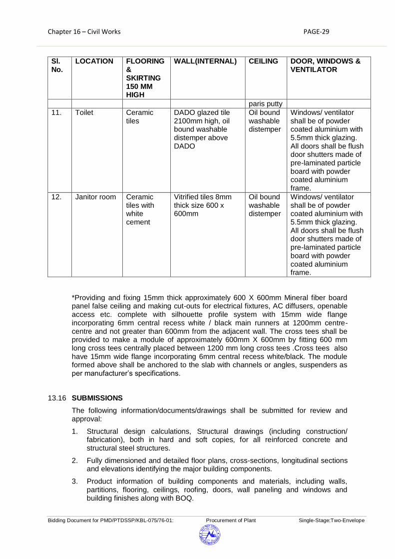
Chapter 16 – Civil Works PAGE-29
Bidding Document for PMD/PTDSSP/KBL-075/76-01: Procurement of Plant Single-Stage:Two-Envelope
Sl. No.
LOCATION FLOORING & SKIRTING 150 MM HIGH
WALL(INTERNAL) CEILING DOOR, WINDOWS & VENTILATOR
paris putty
11. Toilet Ceramic tiles
DADO glazed tile 2100mm high, oil bound washable distemper above DADO
Oil bound washable distemper
Windows/ ventilator shall be of powder coated aluminium with 5.5mm thick glazing. All doors shall be flush door shutters made of pre-laminated particle board with powder coated aluminium frame.
12. Janitor room Ceramic tiles with white cement
Vitrified tiles 8mm thick size 600 x 600mm
Oil bound washable distemper
Windows/ ventilator shall be of powder coated aluminium with 5.5mm thick glazing. All doors shall be flush door shutters made of pre-laminated particle board with powder coated aluminium frame.
*Providing and fixing 15mm thick approximately 600 X 600mm Mineral fiber board panel false ceiling and making cut-outs for electrical fixtures, AC diffusers, openable access etc. complete with silhouette profile system with 15mm wide flange incorporating 6mm central recess white / black main runners at 1200mm centre-centre and not greater than 600mm from the adjacent wall. The cross tees shall be provided to make a module of approximately 600mm X 600mm by fitting 600 mm long cross tees centrally placed between 1200 mm long cross tees .Cross tees also have 15mm wide flange incorporating 6mm central recess white/black. The module formed above shall be anchored to the slab with channels or angles, suspenders as per manufacturer’s specifications.
13.16 SUBMISSIONS
The following information/documents/drawings shall be submitted for review and approval:
1. Structural design calculations, Structural drawings (including construction/ fabrication), both in hard and soft copies, for all reinforced concrete and structural steel structures.
2. Fully dimensioned and detailed floor plans, cross-sections, longitudinal sections and elevations identifying the major building components.
3. Product information of building components and materials, including walls, partitions, flooring, ceilings, roofing, doors, wall paneling and windows and building finishes along with BOQ.

Chapter 16 – Civil Works PAGE-30
Bidding Document for PMD/PTDSSP/KBL-075/76-01: Procurement of Plant Single-Stage:Two-Envelope
4. A detailed schedule of building finishes including colors schemes along with item description.
5. A door & window schedule showing door & window types and locations, lock sets and latch sets and other door hardware along with item details.
Approval of the above information shall be obtained before ordering materials or starting construction/fabrication, as applicable.
13.17 FALSE CEILING
Providing and fixing seamless ceiling with Gypsum board of 12mm thick fixed to the
underside of GI frame work. The GI is fixed to the roof Slab with metal expansion fastener. The joint shall be finished with joint paper tape by using jointing Compound recommended by manufacturer with the approval of NEA/Consultant. The rate includes for all necessary cutting of ceiling for the fixing of complete fixtures.
13.18 UNDER DECK INSULATION
The method of fixing shall consist of slotted M.S. angles of appropriate size
(minimum 65x50x2mm) fixed to soffit of RCC roof slab at 600mm centres in both directions by Rawl plugs of adequate strength. The slots shall have 14g G.I. tie wire drawn through them. 50mm thick insulation mat Fibreglass Crown - 100 or equivalent shall, be made out of fibre-glass or approved equivalent conforming to IS: 8183, backed with 34g aluminium foil and 22g x 12mm mesh wire netting. The net shall be stretched tightly across the slotted angles or slotted plates holding it in place by means of wires. The joints of the wire netting shall be butted and tightly laced down with 14g G.I. wire. The system shall be got approved from NEA/Consultant.
13.19 ELECTRIFICATION
All electrification shall be executed as per details specified elsewhere in the technical specification. All details shall be as per relevant British Standard codes (B S Codes)/ equivalent International Standards.
14. WATER SUPPLY
(i) Water shall be made available by NEA/consultant at any feasible point within
substation boundary at single point to the contractor. Contractor shall state the total water requirement both in terms of quantity and head to NEA/Consultant.
(ii) The contractor shall carry out all the plumbing/erection works required for
supply of water in control room cum administrative building beyond the single point as at (i) above.
(iii) The contractor shall carry out all the plumbing/erection works required for
supply of water to Fire Fighting pump house beyond the single point as at (i) above.

Chapter 16 – Civil Works PAGE-31
Bidding Document for PMD/PTDSSP/KBL-075/76-01: Procurement of Plant Single-Stage:Two-Envelope
(iv) The details of tanks, pipes, fittings, fixtures etc. for water supply are given
elsewhere in the specification under respective sections.
(v) A scheme shall be prepared by the contractor indicating the layout and details of water supply which shall be got approved by NEA/Consultant before actual start of work including all other incidental items not shown or specified but as may be required for complete performance of the works. All drawings shall be prepared by the contractor for approval of NEA/Consultant.
(vi) Bore wells and pumps for water supply are not in the scope of contractor.
15. SEWERAGE SYSTEM
(i) Sewerage system shall be provided for all buildings wherever applicable.
(ii) The Contractor shall construct septic tank and soak pit suitable for 50 users each for control room building, transit camp and township buildings is constructed .If septic and soak pit system is not acceptable by local Nepal Authority, contractor will have to install suitable sewerage system as per local statutory requirement.
(iii) The system shall be designed as per relevant British Standard codes (B S
Codes)/ equivalent International Standards. All drawings shall be prepared by the contractor for approval of NEA/Consultant.
16. GIS HALL CUM CONTROL ROOM BUILDING
16.1 CONTROL ROOM AND GIS HALL
The GIS building shall be of pre-engineered steel structure. Control room building, if attached to GIS hall, shall be of pre-engineered steel structure similar to GIS hall and shall be RCC framed structure, if it is not connected with GIS hall. In case of steel control room building all walls shall be of brick masonry and roof of ground floor shall be of RCC. Internal access to the GIS hall from control room building shall be provided. Provision for extension of GIS hall shall be made for expansion in future. A corridor having minimum width of 1500 mm shall be provided all around GIS hall to
facilitate maintenance of equipments.
Material specification and other details for construction of Pre-engineered steel building shall be as described in subsequent paragraphs. The base plate of steel columns shall be mounted on the RCC foundation by means of hot dip galvanised foundation bolts (Galvanisation of 610 gms/Sq. M). In order to facilitate inspection and maintenance, the structures shall be provided with climbing devices. Separate fire escape doors shall also be provided in the GIS Building. Panels shall be kept in an air-conditioned room. Panel room shall be provided with false ceiling. A glazed partition made of aluminium frame and 5.5mm thick glass shall be provided between GIS hall and panel room. The glazing shall be kept at a sill level of 0.9 m above floor level. The height of glazing shall be minimum 3.0 m above sill

Chapter 16 – Civil Works PAGE-32
Bidding Document for PMD/PTDSSP/KBL-075/76-01: Procurement of Plant Single-Stage:Two-Envelope
level. A Walkway of overall width of not less than 1.0m shall be provided at gantry girder level on the two longer side of GIS hall along with climbing arrangement to facilitate maintenance of crane. Suitable arrangement shall be made on top of the crane to facilitate maintenance of lighting fixtures. Structural steel of walkway shall be finished with priming coat of standard steel primer followed by one coat of epoxy paint and final coating of PU (Minimum 100 Micron). The walls of GIS building and attached panel/relay/AHU room shall be of full brick/concrete block and up to a height of 150 mm above false ceiling level of panel/relay room. Rest portion of building shall be provided with puff sandwiched panels as mentioned elsewhere in technical specification. All external openings for duct entries/exits shall be provided with all round sunshades/chajjas to ensure that no rain water shall directly splashes on sealant. All the material required for Pre-engineered (steel) building shall be procured from reputed manufacturer for which prior approval shall be obtained. Manufacturing of various parts of the building shall start only after approval of “Manufacturing Quality Plan to be prepared by the bidder during detailed engineering stage”. Complete material shall be offered for inspection by QA&I department of Consultant/NEA before dispatch. Inspection shall be carried out based on assembly (fabrication) drawings approved by consultant/NEA and “BILL OF MATERIAL” & Shop drawing prepared by the Manufacturer and certified by the Contractor for its correctness. Approval of BOM and shop drawing from employer is not required.
16.2 MATERIAL SPECIFICATION
16.2.1 Primary members fabricated from plates and sections with minimum yield
strength of 345Mpa or to suit design by continuous double side welding.
16.2.2 Secondary members for Purlins and Grits shall conform to the physical
specification of ASTM A570 (Grade 50) or equivalent BS/equivalent international standards having a minimum yield strength of 345 MPa. The minimum thickness of secondary members shall be 2.5mm.
16.2.3 Rod / ANGLE/pipe bracing shall conform to the physical specification of relevant
BS/equivalent international standards of minimum 245Mpa Yield Strength
16.2.4 All hot rolled sections shall conform to the physical specifications of BS/equivalent international standards. All other miscellaneous secondary members shall have minimum yield strength of 250 MPa.
16.3 DESCRIPTION
16.3.1 PRIMARY MEMBERS:
Primary structural framing shall include the transverse rigid frames, columns, corner columns, end wall wind columns and crane gantry girders and Frames at Door openings.
16.3.2 SECONDARY MEMBERS:

Chapter 16 – Civil Works PAGE-33
Bidding Document for PMD/PTDSSP/KBL-075/76-01: Procurement of Plant Single-Stage:Two-Envelope
Secondary structural framing shall include the purlins, girts, eave struts, wind bracing, flange bracing, base angles, clips, flashings and other miscellaneous structural parts. Suitable wind bracings sag rods to be reckoned while designing the structure.
16.3.3 PURLINS, GIRTS,CLIPS:
Purlins, girts and clips should be of Pre Galvanised steel of 345Mpa having a coating thickness of 275 gms/sq. M inclusive of both sides.
16.3.4 ROOF AND WALL SHEETING
Factory assembled 50mm thick puff (density 40kg/cu.m. +2 Kg/cu m as per BS/equivalent International Standards) sandwiched panels shall be provided. These panels shall be made of puff insulation sandwiched between two high tensile steel sheets each of 0.5 mm thickness. The material of sheets shall confirm to ASTM 792 M Grade 345 with minimum yield strength of 345Mpa . The steel sheets shall be provided with hot dip coating of Zinc aluminium alloy (approximately 55% Al, 43.5% Zn and 1.5 % silicon) .Total mass of zinc aluminium alloy coating shall be minimum 200 gm/Sq. m inclusive of both sides. The tolerance of base metal thickness (BMT) of steel sheet shall be as per BS/equivalent International Standards. After hot dip coating of Zinc aluminium alloy, the sheet shall be provided with steel primer and silicon modified polyester (SMP) paint. The total thickness of primer and paint shall be 40 microns inclusive of both sides (TCT) comprising of 20 microns of SMP paint on top surface and 10 microns of backer coat (polyester coat) on back surface over 5 microns thick primer each on both surfaces with inorganic pigments coated free from heavy metals. Painting shall conform to BS/equivalent International Standards. In case SMP paint is not available, Super Durable Polyester paint (SDP) can also be used by the bidder without cost implication to NEA.
16.3.5 Wall Panels
Wall panel material specifications shall be same as roof panels.
16.3.6 SHEETING FASTENERS:
Standard fasteners shall be self-tapping zinc plated metal screws with EPDM bonded zinc plated washers. All screws shall be colour coated to match roof and wall sheeting.
16.3.7 SEALER:
This is to be applied at all side laps and end laps of roof panels and around self-flashing windows. Sealer shall be pressure sensitive elastomeric Butyl tapes. The sealer shall be non-asphaltic, non-shrinking and nont oxic and shall be superior adhesive metals, plastics and painted at temperatures from 51°C to +104°C.
16.3.8 CLOSURES:
Solid or closed cell closures matching the profiles of the panel shall be installed along the eaves, rake and other locations specified on drawings. Material shall be minimum 26 gauge thick conforming to the physical

Chapter 16 – Civil Works PAGE-34
Bidding Document for PMD/PTDSSP/KBL-075/76-01: Procurement of Plant Single-Stage:Two-Envelope
specification of sheeting material.
16.3.9 FLASHING AND TRIM:
Flashing and / or trim shall be furnished at the rake, corners, eaves, and framed openings and wherever necessary to provide weather tightness and finished appearance. Colour shall be matching with the colour of wall. Material shall be 26 gauge thick conforming to the physical specifications of sheeting.
16.3.10 WALL LIGHTS:
For day lighting purpose of GIS hall, minimum 2 mm thick approved translucent polycarbonate sheet shall be provided for wall lighting in addition to windows for at least 10% of wall area on upper portion of both long walls. The polycarbonate sheet shall be fixed with necessary EPDM, rubber gasket, Silicon Sealant, cold forged fastener, aluminium profile etc. including MS supporting structural steel (conforming to relevant BS/equivalent International Standards) frame to ensure water tight arrangement.
16.3.11 GUTTERS AND DOWN SPOUTS:
Gutters and downspouts shall be adequately designed to ensure proper roof drainage system. Material shall be minimum 26 gauge thick conforming to physical specification of sheeting with matching colour.
16.3.12 PAINTING OF BUILT UP STEEL FRAMES, CRANE GANTRY GIRDERS, and FRAMES AT DOOR OPENINGS, WALK WAY STEEL AND LADDER:
The built up frame ,Crane gantry girders, frames for door openings and steel for walk way shall be applied with a priming coat of standard steel primmer followed by one coat coating of epoxy paint and final coating of PU (Minimum 100 Micron) . The steel work for aforesaid members shall be provided with suitable treatment of shot blasting before application of steel primer. The steel material of ladder shall be galvanized.
16.3.13 COLOUR SCHEME:
Colour Scheme matching with local aesthetic and best industry practices shall be submitted by vendors for approval of NEA. Three alternatives of coloured isometric views with colour codes shall be submitted for approval. The monotony of external colour of sheet shall be avoided by providing vertical bands of different coloured sheet. The colour of roof sheet shall be light coloured to minimize heat absorption. External and internal masonry walls shall be painted with suitable colour matching with colour of steel sheet.
16.4 CONNECTIONS:
16.4.1 SITE CONNECTIONS
a) All primary bolted connections sha l l be provided with galvanized h igh
strength bolts, washers, nuts conforming to specifications of relevant standard.
b) All secondary bolted connections shall be furnished with bolts, nuts, washers conforming to the specifications of grade 4.6 of relevant

Chapter 16 – Civil Works PAGE-35
Bidding Document for PMD/PTDSSP/KBL-075/76-01: Procurement of Plant Single-Stage:Two-Envelope
standard or ASTM-A307.
16.4.2 SHOP CONNECTIONS
All shop connections shall be welded with appropriate arc welding process and weld ing sha l l be in accordance w i t h relevant standard, AWSD 1.1. as appropriate. The Webs should be welded on to the flanges at both the faces at top and bottom for columns, beams and crane girders. Weld material should have strength more than the parent metal.
16.4.3 ROOF & WALL BRACINGS
Roof and wall bracings shall have minimum yield strength of 250 Mpa and shall conform to the specifications of re levant standard.
16.5 INTERNAL FINISH SCHEDULE
The finishing schedule is given in subsequent clauses and table-1. Areas not specified in finish schedule shall be provided with vitrified tile flooring, and Premium Acrylic emulsion paint oil bound washable distemper over two mm thick putty. Paints used in the work shall be of best quality specified in relevant standard.
16.5.1 FLOORING
Flooring in various rooms of control room building and GIS hall shall be as per detailed schedule given in Table -1.
16.5.2 WALLS
All walls of control room building shall be non-load bearing walls. Min. thickness of walls shall be 230 mm (one brick) with 1:6 cement sand mortar. Partition walls (115mm thick) in toilets and pantry can be half brick walls with 1:4 cement sand mortar and two nos. 6mm diameter MS bars at every third course.
In GIS building and the attached panel/relay/AHU room, 230mm thick brick wall shall be provided up to a height of 150 mm above false ceiling level of panel/relay room. 50mm thick puff sandwiched panels as described above shall be provided above brick wall.
16.5.3 ROOF
(A) GIS Building and Control Room (if steel structure)
Roofing Panel: 50mm thick puff (density 40kg/cu.m.) sandwiched panels shall be
provided as described in previous clauses.
16.6 CABLE TRENCH IN GIS HALL
All cable trenches in GIS hall shall be covered with minimum 6mm thick steel chequered plate with suitable stiffeners. Chequered plate and stiffeners shall be painted with two or more coats of Epoxy paint as per relevant standards.
16.7 EXTERNAL PLASTER AND PAINTING
External plaster 18mm thick shall be of 1:6 cement sand plaster in two layers. External surface of the control room building and GIS building (brick wall portion) shall be painted with Premium acrylic smooth exterior paint with silicon additives over and including priming coat of exterior primer as per relevant standards.
16.8 INTERNAL FINISH SCHEDULE

Chapter 16 – Civil Works PAGE-36
Bidding Document for PMD/PTDSSP/KBL-075/76-01: Procurement of Plant Single-Stage:Two-Envelope
Internal finish Schedule for control room building and GIS hall is given in Table - 1 below:
Table -1
S.N. LOCATION FLOORING & SKIRTING 150MM HIGH
WALL (INTERNAL)
CEILING DOOR, WINDOWS & VENTILATOR
1. Control Room
Vitrified tiles size 600 x 600mm
Premium Acrylic emulsion paint on smooth surface applied with plaster of paris (2 mm thick)
False ceiling and White wash above False Ceiling
Windows shall be of 10mm thick toughened glass by using suitable patch fittings/spider fittings. The glass shall extend horizontally from column to column and vertically from sill level of 0.75 m to bottom of lintel/roof beam. All doors shall be glazed powder coated aluminium doors with 5.5.mm Thk. Glazing.
2. Conference Vitrified tiles size 600 x 600mm
Premium Acrylic emulsion paint on smooth surface applied with plaster of paris (2 mm thick)
False ceiling and White wash above False Ceiling
Windows shall be of powder coated aluminium with 5.5mm thick glazing. All doors shall be glazed powder coated aluminium doors with 5.5.mm thk. Glazing.
3. In-charge Room
Vitrified tiles size 600 x 600mm
Premium Acrylic emulsion paint on smooth surface applied with plaster of paris (2 mm thick)
False ceiling and White wash above False Ceiling
Windows shall be of powder coated aluminium with 5.5mm thick glazing. All doors shall be glazed powder coated aluminium doors with 5.5.mm thk. Glazing.
4 Other Office Rooms
Vitrified tiles size 600 x 600mm
Premium Acrylic emulsion paint on
False ceiling and White wash above
Windows shall be of powder coated aluminium with 5.5mm thick

Chapter 16 – Civil Works PAGE-37
Bidding Document for PMD/PTDSSP/KBL-075/76-01: Procurement of Plant Single-Stage:Two-Envelope
S.N. LOCATION FLOORING & SKIRTING 150MM HIGH
WALL (INTERNAL)
CEILING DOOR, WINDOWS & VENTILATOR
smooth surface applied with plaster of paris (2 mm thick)
False Ceiling
glazing. All doors shall be glazed powder coated aluminium doors with 5.5.mm thk. Glazing.
5. Electronics Test Lab.
Vitrified tiles size 600 x 600mm
Premium Acrylic emulsion paint on smooth surface applied with plaster of paris (2 mm thick)
False ceiling and White wash above False Ceiling
Windows shall be of powder coated aluminium with 5.5mm thick glazing. All doors shall be glazed powder coated aluminium doors with 5.5.mm thk. Glazing.
6. ACDB & DCDB Room
62mm thick cement concrete flooring with metallic hardener topping
Oil bound washable distemper on smooth surface applied with plaster of paris putty as per relevant standards
Oil bound washable distemper on smooth surface applied with plaster of paris putty
Steel door 45mm thick double sheet 18 gauge MS steel suitably reinforced and filled with mineral wool. Windows/ventilator shall be of powder coated aluminium with 4mm glazing.
7. Battery room
Vitrified tiles size 600 x 600mm
Premium Acrylic emulsion paint on smooth surface applied with plaster of paris (2 mm thick)
False ceiling and White wash above False Ceiling
Steel door 45mm thick double sheet 18 gauge MS steel suitably reinforced and filled with mineral wool. Windows/ventilator shall be of powder coated aluminium with 4mm glazing.
8. Lobby 18mm thick granite flooring
Premium Acrylic emulsion paint on smooth surface applied with plaster of
False ceiling and White wash above False Ceiling
Windows shall be of powder coated aluminium with 5.5mm thick glazing. All doors shall be glazed powder coated aluminium doors

Chapter 16 – Civil Works PAGE-38
Bidding Document for PMD/PTDSSP/KBL-075/76-01: Procurement of Plant Single-Stage:Two-Envelope
S.N. LOCATION FLOORING & SKIRTING 150MM HIGH
WALL (INTERNAL)
CEILING DOOR, WINDOWS & VENTILATOR
paris (2 mm thick)
with 5.5.mm thk. Glazing.
9. Corridor Vitrified tiles size 600 x 600mm
Premium Acrylic emulsion paint on smooth surface applied with plaster of paris (2 mm thick)
False ceiling and White wash above False Ceiling
Windows shall be of powder coated aluminium with 5.5mm thick glazing. All doors shall be glazed powder coated aluminium doors with 5.5.mm thk. Glazing.
10. Portico 18mm thick granite flooring
Granite cladding
Acrylic emulsion paint over a coat of cement primer on smooth surface applied with readymade putty 1 mm thick as per relevant standards
All doors shall be glazed powder coated aluminium doors with 5.5.mm thk. Glazing.
11. Toilet Ceramic tiles DADO glazed tile 2100mm high, oil bound washable distemper above DADO
Acrylic emulsion paint over a coat of cement primer on smooth surface applied with readymade putty 1 mm thick as per relevant standards
Windows/ ventilator shall be of powder coated aluminium with 5.5mm thick glazing. All doors shall be flush door shutters made of pre-laminated particle board (with powder coated aluminium frame.
12. Janitor room Ceramic tiles DADO glazed tile 2100mm
Acrylic emulsion paint over a
Windows/ ventilator shall be of powder coated aluminium

Chapter 16 – Civil Works PAGE-39
Bidding Document for PMD/PTDSSP/KBL-075/76-01: Procurement of Plant Single-Stage:Two-Envelope
S.N. LOCATION FLOORING & SKIRTING 150MM HIGH
WALL (INTERNAL)
CEILING DOOR, WINDOWS & VENTILATOR
high, oil bound washable distemper above DADO
coat of cement primer on smooth surface applied with readymade putty 1 mm thick as per relevant standards
with 5.5mm thick glazing. All doors shall be flush door shutters made of pre-laminated particle board with powder coated aluminium frame.
13. GIS Hall 62mm thick cement concrete flooring with metallic hardener topping (DSR item code 11.5). Two coats of PU coating over the metallic hardener shall be provided. The final coat of PU shall be applied after Installation of equipment. Total thickness of PU coats shall be minimum 300 microns.
Premium Acrylic emulsion paint having Volatile Organic Compound (VOC) content less than 50gms per litre of approved brand and manufacturer on smooth surface applied with plaster of paris (2 mm thick) over approved primer coat .
In case of RCC roof, ceiling shall be finished with Premium Acrylic emulsion paint having Volatile Organic Compound (VOC) content less than 50gms per litre of approved brand and manufacturer over approved primer coat
Windows/ ventilator shall be of powder coated aluminium with 5.5mm thick glazing. All doors shall be flush door shutters with powder coated aluminium frame.
14. Panel/Relay Room
Vitrified tiles 8mm thick size 600 x 600mm
Premium Acrylic emulsion paint on smooth surface applied with plaster of paris (2 mm thick)
False ceiling and White wash above False Ceiling
Windows shall be of powder coated aluminium with 5.5mm thick glazing. All doors shall be glazed powder coated aluminium doors with 5.5.mm thk. Glazing.
15. AHU Room 62mm thick cement Premium Acrylic Windows/ ventilator
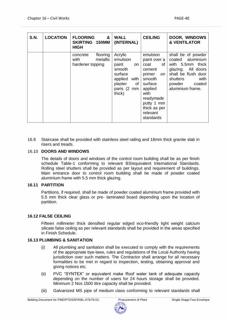
Chapter 16 – Civil Works PAGE-40
Bidding Document for PMD/PTDSSP/KBL-075/76-01: Procurement of Plant Single-Stage:Two-Envelope
S.N. LOCATION FLOORING & SKIRTING 150MM HIGH
WALL (INTERNAL)
CEILING DOOR, WINDOWS & VENTILATOR
concrete flooring with metallic hardener topping
Acrylic emulsion paint on smooth surface applied with plaster of paris (2 mm thick)
emulsion paint over a coat of cement primer on smooth surface applied with readymade putty 1 mm thick as per relevant standards
shall be of powder coated aluminium with 5.5mm thick glazing. All doors shall be flush door shutters with powder coated aluminium frame.
16.9 Staircase shall be provided with stainless steel railing and 18mm thick granite slab in risers and treads.
16.10 DOORS AND WINDOWS
The details of doors and windows of the control room building shall be as per finish schedule Table-1 conforming to relevant BS/equivalent International Standards. Rolling steel shutters shall be provided as per layout and requirement of buildings. Main entrance door to control room building shall be made of powder coated aluminium frame with 5.5 mm thick glazing.
16.11 PARTITION
Partitions, if required, shall be made of powder coated aluminium frame provided with 5.5 mm thick clear glass or pre- laminated board depending upon the location of partition.
16.12 FALSE CEILING
Fifteen millimeter thick densified regular edged eco-friendly light weight calcium silicate false ceiling as per relevant standards shall be provided in the areas specified in Finish Schedule.
16.13 PLUMBING & SANITATION
(i) All plumbing and sanitation shall be executed to comply with the requirements of the appropriate bye-laws, rules and regulations of the Local Authority having jurisdiction over such matters. The Contractor shall arrange for all necessary formalities to be met in regard to inspection, testing, obtaining approval and giving notices etc.
(ii) PVC “SYNTEX” or equivalent make Roof water tank of adequate capacity depending on the number of users for 24 hours storage shall be provided. Minimum 2 Nos 1500 litre capacity shall be provided.
(iii) Galvanized MS pipe of medium class conforming to relevant standards shall

Chapter 16 – Civil Works PAGE-41
Bidding Document for PMD/PTDSSP/KBL-075/76-01: Procurement of Plant Single-Stage:Two-Envelope
be used for internal & external piping work for potable water supply.
(iv) Sand CI pipes with lead joints conforming to relevant standards shall be used for sanitary works above ground level and RCC pipe shall be used for works below ground.
(v) Each toilet shall have the following minimum fittings.
(a) WC (Western type) 390 mm high with toilet paper roll holder and all fittings in toilets attached to conference and sub-station in charge office.
And
WC (Indian Type) Orissa Pattern (580 x 440 mm) with all fittings shall be provided in common toilets.
(b) Urinal (430 x 260 x 350 mm size) with all fittings.
(c) Wash basin (550 x 400 mm) with all fittings.
(d) Bathroom mirror (600 x 450 x 6 mm thick) hard board backing
(e) CP brass towel rail (600 x 20 mm) with C.P. brass brackets
(f) CP Soap holder and CP liquid soap dispenser.
(g) All urinals and washbasins shall be provided with built in sensors.
(vi) Water cooler for drinking water with adequate water storage facility shall be provided and located near control room and not near toilet block.
(viii) 1 no. stainless steel kitchen sink with Drain board (510 x 1040 x 178 mm bowl depth) for pantry shall be provided.
(ix) All fittings, fastener, grating shall be chromium plated.
(x) All sanitary fixtures and fittings shall be of approved quality and type manufactured by well-known manufacturers. All items brought to site must bear identification marks of the type of the Manufacturer.
(xi) Stoneware pipes may be used for soil, waste and drain pipes in the areas not subjected to heavy loads otherwise Heavy duty cast iron pipes may be used.
(xii) Contractor shall provide septic tank and soak pit of adequate capacity to treat the sewage / sullage from the building.
(xiii) Contractor shall implement all other jobs required to complete and commission the building.
17. Retaining Wall:
Retaining wall shall be provided along the periphery of the switchyard and residential area as required by the topography of the area. PCC (1:2:4) shall be provide on the foundation of retaining wall. The retaining wall shall be of RCC cantilever type, consisting of M25 concrete and reinforcement. Chain linked fence as discussed on clause 12 shall be installed on the top of retaining wall. Adequate quantity of weep holes (150 mm diameter pipe) and geotextile/filter materials shall be installed. The retaining wall shall be measured and paid in lump sum basis. Excavation, soling, PCC, concrete, reinforcement, and chain linked fence shall be measured and paid separately in respective items of BPS.
Chapter 16 – Civil Works PAGE-42
Bidding Document for PMD/PTDSSP/KBL-075/76-01: Procurement of Plant Single-Stage:Two-Envelope
18. MODE OF MEASUREMENT
17.1 GEOTECHNICAL INVESTIGATION
This shall include carrying out field tests, laboratory tests, compilation of results and preparation of soil report with recommendations for type of foundations shallow or pile type, suitability of soil for construction of substation etc. The geotechnical investigation work shall be measured on lump sum basis.
17.2 CONTOUR SURVEY, SITE LEVELING AND RETAINING WALLS.
The Contour survey work shall not be measured and paid separately and shall be deemed to be included in the item of site levelling work. Measurement of Earth work in all kind of soil including soft/disintegrated rock in the item of cutting and filling and item of earth work in the filling with borrowed earth shall be made in Cubic meters. No void deduction for 95% compaction.
17.3 EARTHWORK
This shall include excavation in all kinds of soil including rock, all leads and lifts including back filling with suitable earth, compacting, dewatering (if required) and disposal of surplus earth or rock to a suitable location within a lead up to 2 km. The surplus earth if disposed within substation boundary shall be spread in uniform layers each compacted with two passes of suitable compacting equipment. The quantity of excavation for foundations of towers, equipment support structures, all transformers/Reactors, DG Set, firewall, cable trenches, firefighting water tank, buildings and underground water tanks, covered car parking, External lighting poles, control cubicles, marshalling box, retaining walls shall only be measured. The quantity of excavation for roads, rail cum road, drains, culverts, rainwater harvesting, septic tank, soak pit, external water supply system, site surfacing, chain link fencing (including gate) shall not be measured separately and shall be deemed to be included in the composite rates quoted by the bidder for the respective works. All other excavation required for the completion of the work including plinth protection, flooring, sewerage system, manholes, pipes, earth mat etc. shall also not be paid for. The measurement of excavation of all concrete works shall be made considering dimension of the pit leaving 150mm gap around the base pad (lean concrete) or actually excavated pit, whichever is less. The quantity shall be measured in cubic metres.
17.4 PCC
Providing and laying Plain Cement Concrete of all types and at all locations including all leads and lifts. The quantity shall be measured in cubic meters as per lines and levels indicated in the drawings.
17.4.1. PCC 1:2:4 (1 cement : 2 sand : 4 coarse aggregate 20 mm nominal size) shall be measured in flooring of buildings, plinth protection, fencing, transformer/reactor foundation, rail track, drain, culverts, septic tank, chain link fencing, fencing gate ,external lighting poles etc. as indicated in the approved drawings.
17.4.2. PCC 1:4:8 (1 cement : 4 coarse sand : 8 stone aggregate, 40mm nominal size) shall be measured below all foundations of towers, equipment support structures,

Chapter 16 – Civil Works PAGE-43
Bidding Document for PMD/PTDSSP/KBL-075/76-01: Procurement of Plant Single-Stage:Two-Envelope
buildings, firefighting water tanks, covered car parking, cable trench, roads, under flooring, rail-cum-road, transformer foundation, reactor foundation, drain, cable trench crossings, culverts, fence, gate etc. as indicated in the approved drawings.
17.4.3. PCC 1:5:10 (1 Cement: 5 sand: 10 Stone aggregate, 40mm nominal size) shall be provided for site surfacing in switchyard, roof water proofing etc. All other PCC required for the completion of the work including hold fasts of doors/windows/rolling shutters, fixing of plumbing pipes, bedding concrete for sewer lines, embedment of electrical conduits etc. shall not be measured and deemed included in the composite rates quoted by the bidder for respective works. Water proofing compound wherever specified shall be added without any extra cost.
17.5 RCC
Measurement of reinforced cement concrete at all locations shall be made and shall include all leads, lifts, formwork, grouting of pockets and underpinning, (but shall exclude reinforcement & miscellaneous structural steel like inserts etc.), of M25 design mix (Minimum). This shall also include pre-cast RCC work and addition of water proofing compound wherever required for which no additional payment shall be made. The quantity shall be measured in cubic meters as per lines and levels indicated in the drawings. No deduction shall be made for volume occupied by reinforcement/inserts/sleeves and for openings having cross-sectional area up to 0.1 Sq. M
17.6 STEEL REINFORCEMENT
Reinforcement steel shall be measured in length (actual or theoretical as per drawing whichever is less) including hooks, if any, separately for different diameters as actually used in RCC work, excluding overlaps. From the length so measured, the weight of reinforcement shall be calculated in metric tonnes on the basis of sectional weights as adopted by British Standards/equivalent International standards. Wastage, overlaps, couplings, welded joints, spacer bars, chairs, stays, hangers and annealed steel wire or other methods for binding and placing shall not be measured and cost of these items shall be deemed to be included in the rates for reinforcement.
17.7 STONE FILLING OVER GRATING IN TRANSFORMER/REACTOR FOUNDATION
Measurement of stone (40mm nominal size) filling over gratings of transformer/reactor foundations shall be made as per theoretical volume of the space to be filled in the transformer foundation as per approved drawings. This shall be measured in Cu. M.
17.8 MISCELLANEOUS STRUCTURAL STEEL
Measurement for Supply, fabrication, transportation and erection of all miscellaneous structural steel work for rails along with rail fixing details and gratings with supports for transformers/reactors, Cable trenches with covers (Chequered plate covers, cable supports, earthing cleats and edge protection angles etc.), all other steel fittings and fixtures, inserts and embedment in concrete of transformer/reactor foundation and cable trenches shall be made as per approved drawings. The unit rate for this item shall be inclusive of cutting, grinding, drilling, bolting, welding, pre- heating of the welded joints, applying a priming coat of steel primer and anti-corrosive bitumastic paint/ synthetic enamel paint in general but with Zinc Phosphate Primer (Two packs) for grating and support for grating in Transformer foundation (wherever specified),
Chapter 16 – Civil Works PAGE-44
Bidding Document for PMD/PTDSSP/KBL-075/76-01: Procurement of Plant Single-Stage:Two-Envelope
setting of all types of embedment in concrete, etc. Steel required for foundation bolts, nuts and bolt, doors, windows, ventilators, louvers, rolling shutters, chain link fencing, gratings in drains, soil pipes, plumbing pipes, floor traps, embedment’s required for rainwater harvesting, septic tank, soak pit, roof truss and purlins required for fire water tank, etc. shall not be considered for payment and measurements. Quantity shall be measured in metric tonnes.
17.9 ROADS
The measurement for the concrete road shall be made on the basis of area in square meter (m2) of top concrete completed surface of the road and shall be deemed to include all items such as excavation, compaction, rolling, watering, WBM, shoulder, etc. complete as per approved drawing but excluding concreting and reinforcement which shall be paid separately under respective items of BPS.
17.10 ANTI-WEED TREATMENT AND STONE SPREADING
The measurement shall be done for the actual area in square metres of stone spreading provided in the switchyard .It includes providing and spreading of 100mm thickness of uncrushed/crushed/broken stone of 40mm nominal size as per relevant BS codes/equivalent International standards for the specified area. Application of anti-weed treatment including material shall not be measured separately and item would be deemed to be included in the quoted rate of stone spreading in switchyard.
17.11 CHAIN LINK FENCING AND GATE
The measurement shall be made in running metres of the fence provided as per approved drawing. The rate shall be including the post, fencing, MS Flat, painting, brick work and plaster of toe wall etc. complete but excluding the concrete. The switch yard gate shall be measured in numbers.
17.12 CABLE TRENCHES AND CABLE TRENCH CROSSINGS
Earthwork, PCC, RCC, reinforcement steel, RCC Hume pipes and miscellaneous steel required for construction of Cable Trenches and cable trench crossings shall be measured under respective items of Bid price schedule (BPS) as described in clauses of aforesaid paras. No additional payment for brick work, plaster and PVC pipes used for cable trench crossings and sealing of trench mouth shall be admissible.
17.13 DRAINS & CULVERTS
PCC (1:2:4 and 1:4:8) for drains and culverts shall be measured under respective items of Bid price schedule (BPS) as described in clauses of aforesaid paras. All other items like excavation, brick work, plaster and stone pitching except RCC Hume pipes required for completion of drains and culverts shall be deemed to be included in the quoted rate of drain. The quantity for each type of drain section shall be measured in running meters. However, RCC Hume pipes used in culverts shall be measured under respective item of Bid price schedule (BPS) as described in clause of Hume pipes.
17.14 EXTERNAL FINISHING OF RCC FRAMED BUILDINGS/STRUCTURES:
Chapter 16 – Civil Works PAGE-45
Bidding Document for PMD/PTDSSP/KBL-075/76-01: Procurement of Plant Single-Stage:Two-Envelope
The item shall be measured per square meter area basis. Contractor has to assess the quantity as per requirement of Control room cum administrative building, Fire Fighting Pump House, firefighting water tank, switchyard panel room, residential and non-residential buildings, covered car parking and quote for the same separately. This shall include following items.
1) External plastering/cement wash : 18mm Cement plaster in two coats under
layer 12 mm thick cement plaster 1:5 (1 cement: 5 coarse Sand) finished with a top layer of 6 mm thick cement plaster 1:6 (1 cement: 6 fine Sand) for all buildings and firefighting water tank .
2) Providing and applying two or more coats of Acrylic smooth exterior paint over an under coat of suitable primer on new cement plaster surfaces of the control room building, auxiliary building, firefighting pump house building, firefighting water tank, panel room , residential and non-residential buildings and covered car parking. It shall be inclusive of required tools, scaffolding, materials and other painting accessories etc. as per recommendations of manufacturer.
17.15 HUME PIPE
Hume pipe shall be measured diameter-wise and laid as per approved drawings and shall be measured in running meters. The item shall be inclusive of excavation, laying, back filling, jointing etc. but excluding concrete and reinforcement (if any).
17.16 BUILDING
The measurement of all items except excavation, concrete, reinforcement steel of each type of buildings shall be made on area in Square Meter basis. However, the quantity of excavation, concrete, reinforcement steel shall be measured separately under respective items of BPS and described in above paras. The structural steel used for cable tray support, earthing cleat, chequered plates for internal cable trenches of building and panel room wherever applicable shall be measured and paid under miscellaneous steel item of BPS and described above paras. The structural steel and foundation bolts for fixing equipment with foundations/raft within buildings shall not be measured separately which shall be deemed to be included in the quoted rates per square meter of buildings. External Finishing shall be measured and paid in respective items of BPS and described in above paras. The rest of the entire work required to complete the building in all respect as per drawings prepared by contractor and approved by NEA/Consultant shall be deemed to be included in this item rate per square meter area basis.
17.17 RAIL CUM ROAD
The measurement for the rail cum road shall be made in square metres of top concrete completed surface of the rail cum road and shall include all items such as excavation, compaction, rolling, watering, WBM etc. complete as per approved drawing but excluding concrete, reinforcement, structural steel and rails with rail fixing details which shall be measured separately under respective item of BPS and described in above paras.
17.18 SEPTIC TANK AND SOAK PIT

Chapter 16 – Civil Works PAGE-46
Bidding Document for PMD/PTDSSP/KBL-075/76-01: Procurement of Plant Single-Stage:Two-Envelope
This is a lump sum item. The contractor shall be required to complete the work in all respect as per drawings furnished by the contractor and approved by NEA/Consultant. All the items including excavation, masonry work, all types of fillings, all types of pipes including plumbing and vent pipes, all type of fittings etc. shall be deemed to be included in this lump sum rate. However, the concrete (all types) and the reinforcement shall be measured and paid under the respective item mentioned above.
17.19 FIRE WATER TANK
This is a lump sum item. The contractor shall be required to complete the work in all respect as per approved drawings. The items including brick work if any, and miscellaneous steel including steel embedment Rungs, roof truss, corrugated AC Sheet roofing, door, pipe sleeves, internal finish, etc. shall be deemed to be included in this lump sum cost. However, the items like excavation, concrete (all types), reinforcement steel, external finish shall be measured and paid under the respective item of BPS and described in above paras.
17.20 External water supply from Bore-well to Control Room building & GIS building
The external water supply from Bore-well shall be measured diameter-wise in running meters. It shall include all the items such as excavation, piping, pipe fittings, painting, brickwork, sand filling, concrete, valves, chambers cutting chases in walls, openings in RCC and repairs, etc. required to complete the job.
17.21 External Sewage System of Control Room Building and GIS Buildings
It shall be measured diameter wise in running meters. It shall include all the items such as excavation, piping, pipe fittings, manholes, gali trap, gali chamber casing in concrete and repairs etc. required to complete the job. Any modification in the existing sewage system, if required, shall be done by the Contractor without any extra cost implicated to NEA/Consultant.
19. MISCELLANEOUS GENERAL REQUIREMENTS
18.1 Dense concrete with controlled water cement ratio as per BS-code shall be used for
all underground concrete structures such as cable and pipe trenches etc. for achieving water-tightness.
18.2 All joints including construction and expansion joints for the water retaining structures
shall be made water tight by using PVC ribbed water stops with central bulb. However, kicker type (externally placed) PVC water stops shall be used for the base slab and in other areas where it is required to facilitate concreting. The minimum thickness of PVC water stops shall be 5 mm and minimum width shall be 230 mm.
18.3 All steel sections and fabricated structures which are required to be transported on
sea shall be provided with anti-corrosive paint to take care of sea worthiness. 18.4 All mild steel parts used in the water retaining structures shall be hot-double dip
galvanised. The minimum coating of the zinc shall be 750 gm/sq. m. for galvanised structures and shall comply with relevant BS. Galvanizing shall be checked and

Chapter 16 – Civil Works PAGE-47
Bidding Document for PMD/PTDSSP/KBL-075/76-01: Procurement of Plant Single-Stage:Two-Envelope
tested in accordance with relevant BS. The galvanizing shall be followed by the application of an etching primer and dipping in black bitumen in accordance with BS: 3416.
18.5 Bricks having minimum 75 kg/cm2 compressive strength can only be used for
masonry work. Contractor shall ascertain himself at site regarding the availability of bricks of minimum 75 kg/cm2 compressive strength before submitting his offer. The contractor may use concrete blocks of equivalent compressive strength in place of brick work.
18.6 Doors and windows on external walls of the buildings (other than areas provided,
with insulated metal claddings) shall be provided with RCC sun-shade over the openings with 300 mm projection on either side of the openings. Projection of sunshade from the wall shall be minimum 450 mm over window openings and 750 mm over door openings.
18.7 All stairs shall have maximum riser height of 150 mm and a minimum tread width of
300 mm. Minimum width of stairs shall be 1500 mm. Service ladder shall be provided for access to all roofs. RCC fire escape staircase if required as per local bye laws, shall be provided in control buildings.
18.8 Angles 50x50x6 mm (minimum) with lugs shall be provided for edge protection all
round cut outs/openings in floor slab, edges of drains supporting grating covers, edges of RCC cable/pipe trenches supporting covers, edges of manholes supporting covers, supporting edges of manhole precast cover and any other place where breakage of corners of concrete is expected.
18.9 Anti termite chemical treatment for buildings shall be given to all column pits, wall
trenches, foundations, filling below the floors etc. as per relevant International/BS. 18.10 Hand-railing minimum 900mm high shall be provided around all floor/roof openings,
projections/balconies, walk ways, platforms, steel stairs etc. All handrails and ladder pipes shall be 32 mm nominal bore MS pipes (medium class) and shall be galvanised (medium-class as per relevant BS). All rungs for ladder shall also be galvanised as per relevant BS.
For RCC stairs, hand railing with 20 mm square MS bars, balustrades with suitable MS flats & aluminium handrails shall be provided.
18.11 For all civil works covered under this specification, design Mix of Minimum M25 grade
as per relevant International /BS shall be used. Reinforcement steel shall be of minimum Fe 500 grade.
The material specification, workmanship and acceptance criteria shall be as per relevant clauses of applicable International/BS standard.
18.12 Items/components of buildings not explicitly covered in the specification and BPS but
required for completion of the project shall be deemed to be included in the scope.
18.13 Requirement of sulphate resistant cement (SRC) for sub structural works shall be
decided in accordance with the International/BS Standards based on the findings of the detailed soil investigation to be carried out by the Bidder.
18.14 Foundation system adopted by Bidder shall ensure that relative settlement and other
criteria shall be as per provision in relevant BS and other International Standards.
Chapter 16 – Civil Works PAGE-48
Bidding Document for PMD/PTDSSP/KBL-075/76-01: Procurement of Plant Single-Stage:Two-Envelope
18.15 Construction joints shall be as per International/BS standard. 18.16 All building/construction materials shall conform to the best quality specified in
relevant International /BS standard.
20. INTERFACING
The proper coordination & execution of all interfacing civil works activities like fixing of conduits in roofs/walls/floors, fixing of foundation bolts, fixing of lighting fixtures, fixing of supports/embedment’s, provision of cut outs etc. shall be the sole responsibility of the Contractor. He shall plan all such activities in advance and execute in such a manner that interfacing activities do not become bottlenecks and dismantling, breakage etc. is reduced to minimum.
21. STATUTORY RULES
20.1 Contractor shall comply with all the applicable statutory rules pertaining to factories
act (as applicable for the State). Fire Safety Rules of Tariff Advisory- Committee and Water and sewerage Act for pollution control etc.
20.2 Provisions for fire proof doors, no. of staircases, fire escape stairs ,fire separation
wall, plastering on structural members (in fire prone areas) etc. shall be made according to the recommendations of Local Advisory Committee.
20.3 Statutory clearance and norms of Local Pollution Control Board shall be followed as
per Water Act for effluent quality from plant.
22. FIELD QUALITY PLAN
All tests as required in accordance to BS codes or equivalent International standards have to be carried out. The contractor shall prepare field quality plan for civil works as per relevant /BS codes/equivalent International Standards during detailed engineering stage and submit to NEA/Consultant for approval within ONE month after award of work.
23. BRITISH STANDARD CODES
Major British Standard Codes for civil work have been given in the following list. This list is illustrative but not exhaustive. However, for design and engineering relevant BS codes or equivalent International standards shall be referred by the contractor. Relevant portion of BS codes or equivalent international standards referred by the contractor for the design shall be made available to NEA/Consultant if necessary during detailed engineering stage.

Chapter 16 – Civil Works PAGE-49
Bidding Document for PMD/PTDSSP/KBL-075/76-01: Procurement of Plant Single-Stage:Two-Envelope
Sr. No
Standard No Title Year
1 BS 41 Structural steel sections. Specification for hot-rolled sections
2005
2 BS 13771 Methods of test for soils for civil engineering purposes. General requirements and sample preparation
1990
3 BS 4449 Steel for the reinforcement of concrete. Weldable reinforcing steel. Bar, coil and decoiled product. Specification (with A2:2009)
2005
4 BS 4482 Steel fabric for the reinforcement of concrete. Specification
2005
5 BS 4483 Steel fabric for the reinforcement of concrete. Specification
2005
6 BS EN 102102 Hot finished structural hollow sections of non-alloy and fine grain steels. Tolerances, dimensions and sectional properties
2006
7 BS EN 100561 Specification for structural steel equal and unequal Angles. Dimensions
1999
8 BS EN ISO 800001
Quantities and units. General 2013
9 BS 5930 Code of practice for site investigations (with A2:2010) 1999
10 BS EN 199311 Eurocode 3. Design of steel structures. General rules and rules for buildings
2005
11 NA to BS EN 199311
UK National Annex to Eurocode 3. Design of steel structures. General rules and rules for buildings
2008
12 BS EN 199315 Eurocode 3. Design of steel structures. Plated structural elements
2006
13 NA to BS EN 199315
UK National Annex to Eurocode 3. Design of steel structures. Plated structural elements
2008
14 BS EN 199318 Eurocode 3. Design of steel structures. Design of joints 2005
15 NA to BS EN 199318
UK National Annex to Eurocode 3. Design of steel structures. Design of joints
2008
16 BS 60732 Precast concrete masonry units. Guide for specifying precast concrete masonry units
2008
17 BS 7668 Weldable structural steels. Hot finished structural hollow sections in weather resistant steels. Specification
2004
18 BS EN 19971 Eurocode 7. Geotechnical design. General rules 2004
19 NA to BS EN 19971
UK National Annex to Eurocode 7. Geotechnical design. General rules
2007
20 BS EN 19923 Eurocode 2. Design of concrete structures. Liquid retaining and containing structures
2006
21 BS EN 199211 Eurocode 2. Design of concrete structures. General rules and rules for buildings
2004
22 NA to BS EN 199211
UK National Annex to Eurocode 2. Design of concrete structures. General rules and rules for buildings
2005
23 BS 75334 Pavements constructed with clay, natural stone or concrete pavers. Code of practice for the construction of pavements of precast concrete flags or natural stone slabs
2006
24 BS EN 1971 Cement. Composition, specifications and conformity criteria for common cements
2011
25 BS 743 Specification for materials for damp-proof courses 1970
26 BS 8122 Testing aggregates. Methods for determination of densit 1995

Chapter 16 – Civil Works PAGE-50
Bidding Document for PMD/PTDSSP/KBL-075/76-01: Procurement of Plant Single-Stage:Two-Envelope
y
27 BS 952-1 Glass for glazing. Classification 1995
28 BS 952-2 Glass for glazing. Terminology for work on glass 1980
29 BS EN 12620 Aggregates for concrete 2013
30 BS 1125 Specification for WC flushing cisterns (including dual flush cisterns and flush pipes)
1987
31 BS 1188 Specification for ceramic wash basins and pedestals 1974
32 BS 1199 and 1200
Specifications for building sands from natural sources 1976
33 BS EN 13310 Kitchen sinks. Functional requirements and test methods
2003
34 BS 1245 Pedestrian doorsets and door frames made from steel sheet. Specification
2012
35 BS 1254 Specification for WC seats (plastics) 1981
36 BS 1370 Specification for low heat Portland cement 1979
37 BS EN 1008 Mixing water for concrete. Specification for sampling, testing and assessing the suitability of water, including water recovered from processes in the concrete industry, as mixing water for concrete
2002
38 BS 3505 Specification for unplasticized polyvinyl chloride (PVC-U) pressure pipes for cold potable water
1986
39 BS EN 15743 Supersulfated cement. Composition, specifications and conformity criteria
2010
40 BS EN ISO 3766 Construction drawings. Simplified representation of concrete reinforcement
2003
41 BS 8666 Scheduling, dimensioning, bending and cutting of steel reinforcement for concrete. Specification
2005
42 BS 4514 Unplasticized PVC soil and ventilating pipes of 82.4 mm minimum mean outside diameter, and fittings and accessories of 82.4 mm and of other sizes. Specification
2001
43 BS 4551 Mortar. Methods of test for mortar and screed. Chemical analysis and physical testing (with A2:2013)
2005
44 BS EN 122001 Plastics rainwater piping systems for above ground external use. Unplasticized poly (vinyl chloride) (PVC-U). Specifications for pipes, fittings and the system
2000
45 BS EN 1462 Brackets for eaves gutter. Requirements and testing 2004
46 BS EN 607 Eaves gutters and fittings made of PVC-U. Definitions, requirements and testing
2004
47 BS 6262 Code of practice for glazing for buildings 1982
48 BS EN 14411 Ceramic tiles. Definitions, classification, characteristics, evalua tion of conformity and marking
2012
49 BS 6510 Steel framed windows and glazed doors. Specification 2010
50 BS EN 636 Plywood. Specifications 2012
51 NA to BS EN 19923
UK National Annex to Eurocode 2. Design of concrete structures. Liquid retaining and containment structures
2007
52 BS EN 1339
Concrete paving flags. Requirements and test methods 2003
53 BS EN 1340 Concrete kerb units. Requirements and test methods 2003

Chapter 17 –Control and Relay Panels PAGE-1
Bidding Document for PMD/PTDSSP/KBL-075/76-01: Procurement of Plant Single-Stage:Two-Envelope
CHAPTER-17: CONTROL AND RELAY PANELS
1. TYPE OF PANELS
1.1 Simplex Panel
Simplex panel shall consist of a vertical front panel with equipment mounted thereon and having wiring access from rear for control panels & front for relay/protection panels. In case of panel having width more than 800mm, double leaf-doors shall be provided. Doors shall have handles with either built-in locking facility or will be provided with pad-lock.
1.2 CONSTRUCTIONAL FEATURES
2.1. Control and Relay Board shall be of panels of simplex type design as indicated in bill of quantity. It is the responsibility of the Contractor to ensure that the equipment specified and such unspecified complementary equipment required for completeness of the protective/control schemes be properly accommodated in the panels without congestion and if necessary, either add more number of panels or provide panels with larger dimensions. No price increase at a later date on this account shall be allowed. However, the width of panels that are being offered to be placed in existing switchyard control rooms, should be in conformity with the space availability in the control room.
2.2. Panels shall be completely metal enclosed and shall be dust, moisture and vermin proof. The enclosure shall provide a degree of protection not less than IP-31 in accordance with IEC 60529 (Part-1).
2.3. Panels shall be free standing, floor mounting type and shall comprise structural frames completely enclosed with specially selected smooth finished, cold rolled sheet steel of thickness not less than 3 mm for weight bearing members of the panels such as base frame, front sheet and door frames, and 2.0mm for sides, door, top and bottom portions. There shall be sufficient reinforcement to provide level transportation and installation.
2.4. All doors, removable covers of panels shall be gasketed all around with synthetic gaskets Neoprene/EPDM. However, XLPE gaskets can also be used for fixing protective glass doors. Ventilating louvers, if provided shall have screens and filters. The screens shall be made of either brass or GI wire mesh
2.5. Design, materials selection and workmanship shall be such as to result in neat appearance, inside and outside with no welds, rivets or bolt head apparent from outside, with all exterior surfaces tune and smooth.
2.6. Panels shall have base frame with smooth bearing surface, which shall be fixed on the embedded foundation channels/insert plates. Anti vibration strips made of shock absorbing materials that shall be supplied by the contractor, which shall be placed between panel & base frame.
2.7. Cable entries to the panels shall be from the bottom. Cable gland plate fitted on the bottom of the panel shall be connected to earthing of the panel/station through a flexible braided copper conductor rigidly.
2.8. Relay/protection panels of modern modular construction would also be acceptable.
3. MOUNTING
3.1. All equipment on and in panels shall be mounted and completely wired to the terminal blocks ready for external connections. The equipment on front of panel shall be mounted flush.
3.2. Equipment shall be mounted such that removal and replacement can be accomplished individually without interruption of service to adjacent devices and are

Chapter 17 –Control and Relay Panels PAGE-2
Bidding Document for PMD/PTDSSP/KBL-075/76-01: Procurement of Plant Single-Stage:Two-Envelope
readily accessible without use of special tools. Terminal marking on the equipment shall be clearly visible.
3.3. The Contractor shall carry out cut out, mounting and wiring of the free issue items supplied by others which are to be mounted in his panel in accordance with the corresponding equipment manufacturer's drawings. Cut outs if any, provided for future mounting of equipment shall be properly blanked off with blanking plate.
3.4. The centre lines of switches, push buttons and indicating lamps shall not be less than 750mm from the bottom of the panel. The centre lines of relays, meters and recorders shall not be less than 450mm from the bottom of the panel.
3.5. The centre lines of switches, push buttons and indicating lamps shall be matched to give a neat and uniform appearance. Like wise the top lines of all meters, relays and recorders etc. shall be matched.
3.6. No equipment shall be mounted on the doors.
3.7. At existing station, panels shall be matched with other panels in the control room in respect of dimensions, colour, appearance and arrangement of equipment (centre lines of switches, push buttons and other equipment) on the front of the panel.
4. PANEL INTERNAL WIRING
4.1. Panels shall be supplied complete with interconnecting wiring provided between all electrical devices mounted and wired in the panels and between the devices and terminal blocks for the devices to be connected to equipment outside the panels. When panels are arranged to be located adjacent to each other all inter panel wiring and connections between the panels shall be carried out internally
4.2. All wiring shall be carried out with 650V grade, single core, stranded copper conductor wires with PVC insulation. The minimum size of the multi-stranded copper conductor used for internal wiring shall be as follows:
All circuits except current transformer circuits and voltage transfer circuits meant for energy metering - one 1.5mm sq. per lead.
All current transformer circuits - one 2.5 sq.mm per lead.
Voltage transformer circuit (for energy meters): Two 2.5 mm sq. per lead.
4.3. All internal wiring shall be securely supported, neatly arranged, readily accessible and connected to equipment terminals and terminal blocks. Wiring gutters & troughs shall be used for this purpose.
4.4. Auxiliary bus wiring for AC and DC supplies, voltage transformer circuits, annunciation circuits and other common services shall be provided near the top of the panels running throughout the entire length of the panels.
4.5. Wire termination shall be made with solderless crimping type and tinned copper lugs, which firmly grip the conductor. Insulated sleeves shall be provided at all the wire terminations. Engraved core identification plastic ferrules marked to correspond with panel wiring diagram shall be fitted at both ends of each wire. Ferrules shall fit tightly on the wire and shall not fall off when the wire is disconnected from terminal blocks. All wires directly connected to trip circuit breaker or device shall be distinguished by the addition of red coloured unlettered ferrule.
4.6. Longitudinal troughs extending throughout the full length of the panel shall be preferred for inter panel wiring. Inter-connections to adjacent panel shall be brought

Chapter 17 –Control and Relay Panels PAGE-3
Bidding Document for PMD/PTDSSP/KBL-075/76-01: Procurement of Plant Single-Stage:Two-Envelope
out to a separate set of terminal blocks located near the slots of holes meant for taking the inter-connecting wires.
4.7. Contractor shall be solely responsible for the completeness and correctness of the internal wiring and for the proper functioning of the connected equipments.
5. TERMINAL BLOCKS
5.1. All internal wiring to be connected to external equipment shall terminate on terminal blocks. Terminal blocks shall be 650 V grade and have 10 Amps. continuous rating, moulded piece, complete with insulated barriers, stud type terminals, washers, nuts and lock nuts. Markings on the terminal blocks shall correspond to wire number and terminal numbers on the wiring diagrams. All terminal blocks shall have shrouding with transparent unbreakable material.
5.2. Disconnecting type terminal blocks for current transformer and voltage transformer secondary leads shall be provided. Also current transformer secondary leads shall be provided with short circuiting and earthing facilities.
5.3. At least 20% spare terminals shall be provided on each panel and these spare terminals shall be uniformly distributed on all terminal blocks.
5.4. Unless otherwise specified, terminal blocks shall be suitable for connecting the following conductors of external cable on each side
All CT & PT circuits: minimum of two of 2.5mm Sq. copper.
AC/DC Power Supply Circuits: two no of 16mm Sq. Aluminium.
All other circuits: minimum of one of 2.5mm Sq. Copper.
5.5. There shall be a minimum clearance of 250mm between the first row of terminal blocks and the associated cable gland plate or panel side wall. Also the clearance between two rows of terminal blocks edges shall be minimum of 150mm.
5.6. Arrangement of the terminal block assemblies and the wiring channel within the enclosure shall be such that a row of terminal blocks is run in parallel and close proximity along each side of the wiring-duct to provide for convenient attachment of internal panel wiring. The side of the terminal block opposite the wiring duct shall be reserved for the external cable connections. All adjacent terminal blocks shall also share this field wiring corridor. All wiring shall be provided with adequate support inside the panels to hold them firmly and to enable free and flexible termination without causing strain on terminals.
5.7 The number and sizes of the Owner's multi core incoming external cables will be
furnished to the Contractor after placement of the order. All necessary cable
terminating accessories such as gland plates, supporting clamps & brackets,
wiring troughs and gutters etc. (except glands & lugs) for external cables shall
be included in the scope of supply. Terminal blocks provided on Interface
panel used for external wiring from switchyard shall be provided with
necessary surge protection device to safeguard IEDs from transient
voltage surges, spikes.
6. PAINTING
The painting shall be carried out as detailed in Chapter 2–GTR.
7. MIMIC DIAGRAM
7.1. Coloured mimic diagram and symbols showing the exact representation of the

Chapter 17 –Control and Relay Panels PAGE-4
Bidding Document for PMD/PTDSSP/KBL-075/76-01: Procurement of Plant Single-Stage:Two-Envelope
system shall be provided in the front of control panels.
7.2. Mimic diagram shall be made preferably of anodised aluminium or plastic of approved fast colour material, which shall be screwed on to the panel and can be easily cleaned. The mimic bus shall be 2mm thick. The width of the mimic bus shall be 10mm for bus bars and 7mm for other connections. Painted overlaid mimic is also acceptable.
7.3. Mimic bus colour will be decided during detailed Engineering.
7.4. When semaphore indicators are used for equipment position, they shall be so mounted in the mimic that the equipment in close position shall complete the continuity of mimic.
7.5. Indicating lamp, one for each phase, for each bus shall be provided on the mimic to indicate bus charged condition.
8. NAME PLATES AND MARKINGS
8.1. All equipment mounted on front and rear side as well as equipment mounted inside the panels shall be provided with individual name plates with equipment designation engraved. Also on the top of each panel on front as well as rear side, large and bold nameplates shall be provided for circuit/feeder designation.
8.2. All front mounted equipment shall also be provided at the rear with individual name plates engraved with tag numbers corresponding to the one shown in the panel internal wiring to facilitate easy tracing of the wiring.
8.3. Each instrument and meter shall be prominently marked with the quantity measured e.g. KV, A, MW, etc. All relays and other devices shall be clearly marked with manufacturer's name, manufacturer's type, serial number and electrical rating data.
8.4. Name Plates shall be made of non-rusting metal or 3 ply lamicoid. Name plates shall be black with white engraving lettering.
8.5. Each switch shall bear clear inscription identifying its function e.g. 'BREAKER' '52A', "SYNCHRONISING" etc. Similar inscription shall also be provided on each device whose function is not other-wise identified. If any switch device does not bear this inscription separate name plate giving its function shall be provided for it. Switch shall also have clear inscription for each position indication e.g. "Trip- Neutral-Close", "ON-OFF", "R-Y-B-OFF" etc
8.6. All the panels shall be provided with name plate mounted inside the panel bearing LOA No & Date, Name of the Substation & feeder and reference drawing number.
9. MISCELLANEOUS ACCESSORIES
9.1. Plug Point: 230V, Single phase 50Hz, AC socket with switch suitable to accept 5 Amps and 15 Amps pin round standard plug, shall be provided in the interior of each cubicle with ON-OFF switch.
9.2. Interior Lighting: Each panel shall be provided with LED type lighting fixture (Min 7 Watt) rated for 230 Volts, single phase, 50 Hz supply for the interior illumination of the panel controlled by the respective panel door switch. Adequate lighting shall also be provided for the corridor in Duplex panels.
9.3. Switches and Fuses: Each panel shall be provided with necessary arrangements for receiving, distributing and isolating of DC and AC supplies for various control, signaling, lighting and space heater circuits. The incoming and sub-circuits shall be separately provided with Fuses. Selection of the main and sub-circuit Fuses rating shall be such as to ensure selective clearance of sub-circuit faults. Voltage

Chapter 17 –Control and Relay Panels PAGE-5
Bidding Document for PMD/PTDSSP/KBL-075/76-01: Procurement of Plant Single-Stage:Two-Envelope
transformer circuits for relaying and metering shall be protected by fuses. All fuses shall be HRC cartridge type conforming to relevant international standard.mounted on plug-in type fuse bases. The short time fuse rating of Fuses shall be not less than 9 KA. Fuse carrier base shall have imprints of the fuse 'rating' and 'voltage'. MCB’s shall also accepted for protecting the relaying and metering circuits instead of HRC Fuse.
9.4. Space Heater: Each panel shall be provided with a thermostatically connected
space heater rated for 230V, single phase, 50 Hz AC supply for the internal heating of the panel to prevent condensation of moisture. The fittings shall be complete with switch unit.
10. EARTHING
10.1. All panels shall be equipped with an earth bus securely fixed. Location of earth bus shall ensure no radiation interference from earth systems under various switching conditions of isolators and breakers. The material and the sizes of the bus bar shall be at least 25 X 6 sq.mm copper with threaded holes at a gap of 50 mm with provision of bolts and nuts for connection with cable armours and mounted equipment etc for effective earthing. When several panels are mounted adjoining each other, the earth bus shall be made continuous and necessary connectors and clamps for this purpose shall be included in the scope of supply of Contractor. Provision shall be made for extending the earth bus bars to future adjoining panels on either side.
10.2. Provision shall be made on each bus bar of the end panels for connecting Substation earthing grid. Necessary terminal clamps and connectors for this purpose shall be included in the scope of supply of Contractor.
10.3. All metallic cases of relays, instruments and other panel mounted equipment including gland plate, shall be connected to the earth bus by copper wires of size not less than 2.5 sq. mm. The colour code of earthing wires shall be green.
10.4. Looping of earth connections which would result in loss of earth connection to other devices when the loop is broken, shall not be permitted. However, looping of earth connections between equipment to provide alternative paths to earth bus shall be provided.
10.5. VT and CT secondary neutral or common lead shall be earthed at one place only at the terminal blocks where they enter the panel. Such earthing shall be made through links so that earthing may be removed from one group without disturbing continuity of earthing system for other groups.
10.6. An electrostatic discharge arrangement shall be provided in each panel so as to
discharge human body before he handles the equipments inside the panels.
11. INDICATING INSTRUMENTS & TRANSDUCERS FOR CONTROL PANEL:
All instruments, meters and transducers shall be enclosed in dust proof, moisture resistant, black finished cases and shall be suitable for tropical use. All megawatt , megavar, Bus voltage and frequency indicating instruments shall be provided with individual transducers and these shall be calibrated along with transducers to read directly the primary quantities. They shall be accurately adjusted and calibrated at works and shall have means of calibration check and adjustment at site. The supplier shall submit calibration certificates at the time of delivery. However no separate transducers are envisaged for digital bus voltmeters and digital frequency meters and the indicating meters provided in the synchronising equipment.
11.1 Indicating Instruments

Chapter 17 –Control and Relay Panels PAGE-6
Bidding Document for PMD/PTDSSP/KBL-075/76-01: Procurement of Plant Single-Stage:Two-Envelope
11.1.1.1 Unless otherwise specified, all electrical indicating instruments shall be of digital type suitable for flush mounting.
11.1.2 Instruments shall have 4-digit display; display height being not less than 25 mm
11.1.3 Instrument shall confirm to relevant IEC and shall have an accuracy class of 1.5 or better. Watt and Var meters shall have an indication of (+) and (-) to indicate EXPORT and IMPORT respectively.
11.1.4 Digital voltage and frequency meters shall be of class: 0.5 and shall have digital display of 5 and 4 digits respectively, with display size, not less than 25mm (height).
11.2. Transducers
11.2.1. Transducers (for use with Indicating Instruments and Telemetry/Data Communication application) shall in general conform to IEC:688-1
11.2.2. The transducers shall be suitable for measurement of active power, reactive power, voltage, current and frequency in three phase four wire unbalanced system.
11.2.3. The input to the transducers will be from sub-station current & potential transformers. The output shall be in milli ampere D.C. proportional to the input & it shall be possible to feed the output current directly to the telemetry terminal or indicating instruments.
11.2.4. The transducer characteristic shall be linear throughout the measuring range.
11.2.5. The transducer output shall be load independent.
11.2.6. The input & output of the transducer shall be galvanically isolated.
11.2.7. Each transducer shall be housed in a separate compact case and have suitable terminals for inputs & outputs.
11.2.8. The transducers shall be suitably protected against transient high peaks of voltage & current.
11.2.9. The transducer shall withstand indefinitely without damage and work satisfactorily at 120% of the rated voltage and 120% of the rated input current as applicable.
11.2.10. All the transducers shall have an output of 4-20 mA.
11.2.11. The response time of the transducers shall be less than 1 second.
11.2.12. The accuracy class of transducers shall be 1.0 or better for voltage/current transducer, 0.5 or better for watt/VAR transducer and 0.2 or better for frequency transducer.
11.2.13. The transducers shall have a low AC ripple on output less than 1%.
11.2.14. The transducer shall have dual output.
12. ANNUNCIATION SYSTEM for Control Panel
12.1. Alarm annunciation system shall be provided in the control board by means of visual and audible alarm in order to draw the attention of the operator to the abnormal operating conditions or the operation of some protective devices. The annunciation equipment shall be suitable for operation on the voltages specified in this specification.
12.2. The visual annunciation shall be provided by annunciation facia, mounted flush on the top of the control panels.

Chapter 17 –Control and Relay Panels PAGE-7
Bidding Document for PMD/PTDSSP/KBL-075/76-01: Procurement of Plant Single-Stage:Two-Envelope
12.3. The annunciation facia shall be provided with translucent plastic window for alarm point with approximate size of 35mm x 50mm. The facia plates shall be engraved in black lettering with respective inscriptions. Alarm inscriptions shall be engraved on each window in not more than three lines and size of the lettering shall not be less than 5 mm.
12.4. Each annunciation window shall be provided with two white lamps in parallel to provide safety against lamp failure. Long life lamps shall be used. The transparency of cover plates and wattage of the lamps provided in the facia windows shall be adequate to ensure clear visibility of the inscriptions in the control room having high illumination intensity (350 Lux), from the location of the operator's desk.
12.5. All Trip facia shall have red colour and all Non-trip facia shall have white colour.
12.6. The audible alarm shall be provided by Buzzer/ Hooter /Bell having different sounds and shall be used as follows.
Hooter Alarm Annunciation
Bell Annunciation DC failure
Buzzer AC supply failure
12.7. Sequence of operation of the annunciator shall be as follows :
S. N. Alarm Condition Fault Contact
Visual Annunciation
Audible Annunciation
1. Normal Open OFF OFF
2. Abnormal Close Flashing ON
3. Accept Push Button Pressed
Close
Open
Steady On
Steady On
OFF
OFF
4. Reset Push Button Pressed
Close
Open
On
Off
OFF
OFF
5. Lamp Test Push Button Pressed
Open Steady On OFF
12.8. Audible annunciation for the failure of DC supply to the annunciation system shall be provided and this annunciation shall operate on 230 Volts AC supply. On failure of the DC to the annunciation system for more than 2 or 3 seconds (adjustable setting), a bell shall sound. A separate push button shall be provided for the cancellation of this audible alarm alone but the facia window shall remain steadily lighted till the supply to annunciation system is restored.
12.9. A separate voltage check relay shall be provided to monitor the failure of supply (230V AC) to the scheme mentioned in Clause above. If the failure of supply exists for more than 2 to 3 seconds, this relay shall initiate visual and audible annunciation. Visual and audible annunciation for the failure of AC supply to the annunciation system shall be provided and this annunciation shall operate on Annunciation DC and buzzer shall sound.
12.10. The annunciation system described above shall meet the following additional requirements :
a) The annunciation system shall be capable of catering to at least 20
Chapter 17 –Control and Relay Panels PAGE-8
Bidding Document for PMD/PTDSSP/KBL-075/76-01: Procurement of Plant Single-Stage:Two-Envelope
simultaneous signals at a time.
b) One set of the following push buttons shall be provided on each control panel:
Reset push button for annunciation system
Accept push button for annunciation system
Lamp test push button for testing the facia windows
c) One set of the following items shall be provided common for all the control panel (not applicable for extension of substation) :
Flasher relay for annunciation system
Push button for Flasher test
Three Push buttons for test of all audible alarm systems
d) These testing circuits shall be so connected that while testing is being done, it shall not prevent the registering of any new annunciation that may land during the test.
e) The annunciation shall be repetitive type and shall be capable of registering the fleeting signal. Minimum duration of the fleeting signal registered by the system shall be 15 milli seconds.
f) In case of static annunciator scheme, special precaution shall be taken to ensure that spurious alarm condition does not appear due to influence of external electromagnetic/ electrostatic interference on the annunciator wiring and switching disturbances from the neighbouring circuits within the panels and the static annunciator shall meet the high voltage susceptibility test , impulse voltage withstand test , high frequency disturbance test– class III and fast transient disturbance test –level III as per IEC 60255.
12.11. The annunciation system to be supplied for existing sub-stations shall be engineered as an extension to the existing scheme.
13. SWITCHES
13.1. Control and instrument switches shall be rotary operated type with escutcheon plates clearly marked to show operating position and circuit designation plates and suitable for flush mounting with only switch front plate and operating handle pro-jecting out.
13.2. The selection of operating handles for the different types of switches shall be as follows :
Breaker, Isolator control switches : Pistol grip, black
Synchronising switches : Oval, Black, Keyed handle (one common removable handle for a group of switches or locking facility having common key)
synchronising Selector switches : Oval or knob, black
Instrument switches : Round, knurled, black
Protection Transfer switch, Local/Remote/Selector Switch
: Pistol grip, lockable and black.
13.3. The control switch of breaker and isolator shall be of spring return to neutral type. The switch shall have spring return from close and trip positions to "after close"

Chapter 17 –Control and Relay Panels PAGE-9
Bidding Document for PMD/PTDSSP/KBL-075/76-01: Procurement of Plant Single-Stage:Two-Envelope
and "after trip" positions respectively.
13.4. Instrument selection switches shall be of maintained contact (stay put) type. Ammeter selection switches shall have make-before-break type contacts so as to prevent open circuiting of CT secondary when changing the position of the switch. Voltmeter transfer switches for AC shall be suitable for reading all line- to-line and line-to-neutral voltages for non- effectively earthed systems and for reading all line to line voltages for effectively earthed systems.
13.5. Synchronising switches shall be of maintained contact (stay put) type having a common removable handle for a group of switches. The handle shall be removable only in the OFF position and it shall be co-ordinated to fit into all the synchronising switches. These switches shall be arranged to connect the syn-chronising equipment when turned to the 'ON' position. One contact of each switch shall be connected in the closing circuit of the respective breaker so that the breaker cannot be closed until the switch is turned to the 'ON' position.
13.6. Lockable type of switches which can be locked in particular positions shall be provided when specified. The key locks shall be fitted on the operating handles.
13.7. The contacts of all switches shall preferably open and close with snap action to minimise arcing. Contacts of switches shall be spring assisted and contact faces shall be with rivets of pure silver or silver alloy. Springs shall not be used as current carrying parts
13.8. The contact combination and their operation shall be such as to give completeness to the interlock and function of the scheme.
13.9. The contact rating of the switches shall be as follows :
Description Contact Rating in Amps
220V DC 50V DC 230V AC
Make and carry 10 10 10
Continuously
Make and carry 30 30 30
for 0.5 sec.
Break for Resistive load 3 20 7
Break for Inductive load 0.2 - -
with L/R = 40m sec.
14. INDICATING LAMPS
14.1. Indicating lamps shall be of cluster LED type suitable for panel mounting with rear terminal connections. Lamps shall be provided with series connected resistors preferably built in the lamp assembly. Lamps shall have translucent lamp covers to diffuse lights coloured red, green, amber, clear white or blue as specified. The lamp cover shall be preferably of screwed type, unbreakable and moulded from heat resisting material.
14.2. The lamps shall be provided with suitable resistors.

Chapter 17 –Control and Relay Panels PAGE-10
Bidding Document for PMD/PTDSSP/KBL-075/76-01: Procurement of Plant Single-Stage:Two-Envelope
14.3. Lamps and lenses shall be interchangeable and easily replaceable from the front of the panel. Tools, if required for replacing the bulbs and lenses shall also be included in the scope of the supply.
14.4. The indicating lamps with resistors shall withstand 120% of rated voltage on a continuous basis.
15. POSITION INDICATORS (if Applicable)
15.1. Position indicators of "SEMAPHORE" type shall be provided when specified as part of the mimic diagrams on panels for indicating the position of circuit breakers, isolating/earthing switches etc. The indicator shall be suitable for semi-flush mounting with only the front disc projecting out and with terminal connection from the rear. Their strips shall be of the same colour as the associated mimic.
15.2. Position indicator shall be suitable for DC Voltage as specified. When the supervised object is in the closed position, the pointer of the indicator shall take up a position in line with the mimic bus bars, and at right angles to them when the object is in the open position. When the supply failure to the indicator occurs, the pointer shall take up an intermediate position to indicate the supply failure.
15.3. The rating of the indicator shall not exceed 2.5 W.
15.4. The position indicators shall withstand 120% of rated voltage on a continuous basis.
16. SYNCHRONISING EQUIPMENT
16.1. For sub-station equipped with sub-station Automation system, the requirement of synchronisation is specified in chapter Sub-station Automation System and the same shall prevail. For other sub-station which is not equipped with Sub-sub-station automation system following shall be applicable as per requirement.
16.2. The synchronising instruments shall be mounted either on a synchronising trolley or on a synchronising panel. The panel/ trolley shall be equipped with double analog voltmeters and double analog frequency meters, synchroscope and lamps fully wired. The size of voltmeters and frequency meters provided in the synchronising panel shall not be less than 144 X 144 sq.mm. Suitable auxiliary voltage transformers wherever necessary shall also be provided for synchronising condition. In case the synchroscope is not continuously rated, a synchroscope cut-off switch shall be provided and an indicating lamp to indicate that the synchroscope is energised, shall also be provided.
16.3. Synchronising check relay with necessary ancillary equipment’s shall be provided which shall permit breakers to close after checking the requirements of synchronising of incoming and running supply. The phase angle setting shall not exceed 35 degree and have voltage difference setting not exceeding 10%. This relay shall have a response time of less than 200 milliseconds when the two system conditions are met within present limits and with the timer disconnected. The relay shall have a frequency difference setting not exceeding 0.45% at rated value and at the minimum time setting. The relay shall have an adjustable time setting range of 0.5-20 seconds. A guard relay shall be provided to prevent the closing attempt by means of synchronising check relay when control switch is kept in closed position long before the two systems are in synchronism
16.4. The synchronising panel shall be draw out and swing type which can be swivelled in left and right direction. The synchronising panel shall be placed along with control panels and the number of synchronising panel shall be as indicated in SCHEDULES OF RATES AND PRICES. The incoming and running bus wires of

Chapter 17 –Control and Relay Panels PAGE-11
Bidding Document for PMD/PTDSSP/KBL-075/76-01: Procurement of Plant Single-Stage:Two-Envelope
VT secondary shall be connected and run as bus wires in the control panels and will be extended to synchronising panel for synchronisation of circuit breakers. The selector switch provided for each circuit breaker in respective control panels shall be lockable type with a common key so that only one selector switch is kept in synchronising mode at a time.
16.5. Alternatively, the trolley shall be of mobile type with four rubber-padding wheels capable of rotating in 360 degree around the vertical axis. Suitable bumpers with rubber padding shall be provided all around the trolley to prevent any accidental damage to any panel in the control room while the trolley is in movement. The trolley shall have two meter long flexible cord fully wired to the instruments and terminated in a plug in order to facilitate connecting the trolley to any of the panels. The receptacle to accept the plug shall be provided on the panel.
16.6. At existing sub-stations, the synchronising scheme shall be engineered to be compatible with the existing synchronising scheme and synchronising socket/switch on the panel. In substations, where synchronising panels are available, the bidder shall carry out the shifting of the above panels, if required, to facilitate the extension of control panel placement.
17 RELAYS
16.7. All relays shall conform to the requirements of IEC-60255/IEC 61000 or other applicable standards. Relays shall be suitable for flush or semi-flush mounting on the front with connections from the rear.
16.8. All protective relays shall be of numerical type and communication protocol shall be as per IEC 61850. Further, the test levels of EMI as indicated in IEC 61850 shall be applicable to these relays. Protective relays shall also fulfil the requirements specified for Protection IEDs in Chapter-Substation automation system
16.9. All protective relays shall be in draw out or plug-in type/modular cases with proper testing facilities. Necessary test plugs/test handles shall be supplied loose and shall be included in contractor's scope of supply.
16.10. All AC operated relays shall be suitable for operation at 50 Hz. AC Voltage operated relays shall be suitable for 110 Volts VT secondary and current operated relays for 1 amp CT secondary. All DC operated relays and timers shall be designed for the DC voltage specified, and shall operate satisfactorily between 80% and 110% of rated voltage. Voltage operated relays shall have adequate thermal capacity for continuous operation.
16.11. The protective relays shall be suitable for efficient and reliable operation of the protection scheme described in the specification. Necessary auxiliary relays and timers required for interlocking schemes for multiplying of contacts suiting contact duties of protective relays and monitoring of control supplies and circuits, lockout relay monitoring circuits etc. also required for the complete protection schemes described in the specification shall be provided. All protective relays shall be provided with at least two pairs of potential free isolated output contacts. Auxiliary relays and timers shall have pairs of contacts as required to complete the scheme; contacts shall be silver faced with spring action. Relay case shall have adequate number of terminals for making potential free external connections to the relay coils and contacts, including spare contacts.
16.12. Timers shall be of solid state type. Time delay in terms of milliseconds obtained by the external capacitor resistor combination is not preferred and shall be avoided.
16.13. No control relay, which shall trip the power circuit breaker when the relay is de-

Chapter 17 –Control and Relay Panels PAGE-12
Bidding Document for PMD/PTDSSP/KBL-075/76-01: Procurement of Plant Single-Stage:Two-Envelope
energised, shall be employed in the circuits.
16.14. Provision shall be made for easy isolation of trip circuits of each relay for the purpose of testing and maintenance.
16.15. Auxiliary seal-in-units provided on the protective relays shall preferably be of shunt reinforcement type. If series relays are used the following shall be strictly ensured:
(a) The operating time of the series seal-in-unit shall be sufficiently shorter than that of the trip coil or trip relay in series with which it operates to ensure definite operation of the flag indicator of the relay.
(b) Seal-in-unit shall obtain adequate current for operation when one or more relays operate simultaneously.
(c) Impedance of the seal-in-unit shall be small enough to permit satisfactory operation of the trip coil on trip relays when the D.C. Supply Voltage is minimum.
(d) Trip-circuit seal-in is required for all trip outputs, irrespective of the magnitude of the interrupted current. The trip-circuit seal-in logic shall not only seal-in the trip output(s),but also the relevant initiation signals to other scheme functions, (e.g. initiate signals to the circuit-breaker failure function, reclosing function etc.), and the alarm output signals.
(e) Two methods of seal-in are required, one based on the measurement of AC current, catering for those circumstances for which the interrupted current is above a set threshold, and one based on a fixed time duration, catering for those circumstances for which the interrupted current is small (below the set threshold).
(f) For the current seal-in method, the seal-in shall be maintained until the circuit-breaker opens, at which time the seal-in shall reset and the seal-in method shall not now revert to the fixed time duration method. For this seal-in method, the seal-in shall be maintained for the set time duration. For the line protection schemes, this time duration shall be independently settable for single- and three-pole tripping.
(g) Seal-in by way of current or by way of the fixed duration timer shall occur irrespective of whether the trip command originates from within the main protection device itself (from any of the internal protection functions), or from an external device with its trip output routed through the main protection device for tripping. Trip-circuit seal-in shall not take place under sub-harmonic conditions (e.g. reactor ring down).
16.16. The setting ranges of the relays offered, if different from the ones specified shall also be acceptable if they meet the functional requirements.
16.17. Any alternative/additional protections or relays considered necessary for providing complete effective and reliable protection shall also be offered separately. The acceptance of this alternative/ additional equipment shall lie with the OWNER.
16.18. All relays and their drawings shall have phase indications as R-Red, Y-yellow, B-blue.
17.12. For numerical relays, the scope shall include the following:
a) Necessary software and hardware to up/down load the data to/from the relay from/to the personal computer installed in the substation. However, the supply of PC is not covered under this clause.
b) The relay shall have suitable communication facility for future connectivity to SCADA. The relay shall be capable of supporting IEC 61850 protocol.

Chapter 17 –Control and Relay Panels PAGE-13
Bidding Document for PMD/PTDSSP/KBL-075/76-01: Procurement of Plant Single-Stage:Two-Envelope
c) In case of line protection and transformer/reactor protection, the features like fault recorder and event logging function as available including available as optional feature in these relays shall be supplied and activated at no extra cost to the owner. Also necessary software/ hardware for automatic uploading to station HMI/DR work station (as applicable) shall be supplied. It is to be clearly understood that these shall be in addition to Fault recorder function as specified at clause no. 28.
18 TRANSMISSION LINE PROTECTION
18.1 All relays shall be suitable for series compensated line.
18.2 The line protection relays are required to protect the line and clear the faults on line within shortest possible time with reliability, selectivity and full sensitivity to all type of faults on lines. The general concept is to have two main protections having equal performance requirement specially in respect of time as called Main-I and Main-II for 400KV and 220KV transmission lines and Main and back up protection for 132 KV transmission lines.
18.3 The Transmission system for which the line protection equipment are required is indicated in Chapter 1 – Project Specific Requirement
18.4 The maximum fault current could be as high as 63kA but the minimum fault current could be as low as 20% of rated current of CT secondary. The starting & measuring relays characteristics should be satisfactory under these extremely varying conditions.
18.5 The protective relays shall be suitable for use with capacitor voltage transformers having non-electronic damping and transient response as per IEC.
18.6 Fault Recorder, Distance to fault Locator and Over voltage relay (stage -1/2) functions if offered as an integral part of line protection relays, shall be acceptable provided these meet the technical requirements as specified in the respective clauses.
18.7 Auto reclose relay function if offered as an integral part of line distance protection relay, shall be acceptable for 132 KV lines & below lines only provided the auto reclose
relay feature meets the technical requirements as specified in the respective clause.
18.8 The following protections shall be provided for each of the Transmission lines:
For 400 KV/ 220KV
Main-I: Distance protection scheme.
Main-II: Distance protection scheme
Main-I & Main-II relay shall be of different make &model. Same make relay shall be acceptable only if they are of different hardware & manufacturing platform.
For 132KV
Main: Numerical distance protection scheme
Back up: Directional Over Current and Earth fault Protection
The detailed description of line protections is given here under.
18.9 Main-I and Main-II Distance Protection scheme:
(a) shall have continuous self monitoring and diagnostic feature
(b) shall be non-switched type with separate measurements for all phase to phase and phase to ground faults

Chapter 17 –Control and Relay Panels PAGE-14
Bidding Document for PMD/PTDSSP/KBL-075/76-01: Procurement of Plant Single-Stage:Two-Envelope
(c) shall have stepped time-distance characteristics and three independent zones (zone 1, zone-2 and zone-3)
(d) shall have mho or quadrilateral or other suitably shaped characteristics for zone-1 , zone-2 and zone- 3
(e) shall have following maximum operating time (including trip relay time, if any) under given set of conditions and with CVT being used on line (with all filters included)
(i) for 400KV/ 220 KV lines:
For Source to Impedance ratio: 4 15
Relay setting (Ohms) (10 or 20) and 2 2
Fault Locations
(as % of relay setting)
50 50
Fault resistance (Ohms) 0 0
Maximum operating time (Milliseconds )
40 for all faults 45 for 3 ph. Faults & 60 for all other faults
(ii) for 132 KV lines:
A relaxation of 5 ms in above timings is allowed for 132 KV lines.
(f) The relay shall have an adjustable characteristics angle setting range of 30 -85 degree or shall have independent resistance(R) and reactance (X) setting.
(g) shall have two independent continuously variable time setting range of 0-3 seconds for zone-2 and 0-5 seconds for zone-3
(h) shall have resetting time of less than 55 milli-seconds (including the resetting time of trip relays)
(i) shall have facilities for offset features with adjustable 10-20% of Zone-3 setting
(j) shall have variable residual compensation
(k) shall have memory circuits with defined characteristics in all three phases to ensure correct operation during close-up 3 phase faults and other adverse conditions and shall operate instantaneously when circuit breaker is closed to zero-volt 3 phase fault
(l) shall have weak end in-feed feature
(m) shall be suitable for single & three phase tripping
(n) shall have a continuous current rating of two times of rated current. The voltage circuit shall be capable of operation at 1.2 times rated voltage. The relay shall also be capable of carrying a high short time current of 70 times rated current without damage for a period of 1 sec.
(o) shall be provided with necessary self reset type trip duty contacts for completion of the scheme (Minimum number of these trip duty contacts shall be four per phase) either through built in or through separate high speed trip relays. Making capacity of these trip contacts shall be 30 amp for 0.2 seconds with an inductive load of L/R > 10 mill seconds. If separate high speed trip relays are used , the operating time of the same shall not be more than 10 milliseconds
(p) shall be suitable for use in permissive under reach/ over reach/ blocking

Chapter 17 –Control and Relay Panels PAGE-15
Bidding Document for PMD/PTDSSP/KBL-075/76-01: Procurement of Plant Single-Stage:Two-Envelope
communication mode
(q) shall have suitable number of potential free contacts for Carrier aided Tripping, Auto reclosing, CB failure, Disturbance recorder & Data acquisition system
(r) include power swing blocking protection which shall
have suitable setting range to encircle the distance protection described above
block tripping during power swing conditions
release blocking in the event of actual fault
(s) include fuse failure protection which shall monitor all the three fuses of C.V.T. and associated cable against open circuit
inhibit trip circuits on operation and initiate annunciation
have an operating time less than 7 milliseconds
remain inoperative for system earth faults
(t) include a directional back up Inverse Definite Minimum Time (IDMT) earth fault relay with normal inverse characteristics as per IEC 60255-3 as a built in feature or as a separate unit for 400 kV & 220KV transmission lines
(u) Must have a current reversal guard feature.
(v) Shall have Stub protection function with current setting minimum range of 1 to 3 pu with definite time delay setting minimum range of 0 to 100msec.
(w) have feature of load encroachment blinder to safeguard the protection trip during heavy line loading condition.
18.10 Back-up Directional Over Current and Earth fault protection scheme
(a) shall have three over current and one earth fault element(s) which shall be either independent or composite unit(s)
(b) shall include necessary VT fuse failure relays for alarm purposes
(c) over current elements shall
have IDMT characteristic with a definite minimum time of 3.0 seconds at 10 times setting
have a variable setting range of 50-200% of rated current
have a characteristic angle of 30/45 degree lead
include hand reset flag indicators or LEDs
(d) earth fault element shall
have IDMT characteristic with a definite minimum time of 3.0 seconds at 10 times setting
have a variable setting range of 20-80% of rated current
have a characteristic angle of 45/60 degree lag
include hand reset flag indicators or LEDs
include necessary separate interposing voltage transformers or have

Chapter 17 –Control and Relay Panels PAGE-16
Bidding Document for PMD/PTDSSP/KBL-075/76-01: Procurement of Plant Single-Stage:Two-Envelope
internal feature in the relay for open delta voltage to the relay
18.11 LINE OVER VOLTAGE PROTECTION RELAY shall
(a) monitor all three phases
(b) have two independent stages
(c) stage- I & II as built-in with line distance relays Main I & II respectively are acceptable
(d) have an adjustable setting range of 100-170% of rated voltage with an adjustable time delay range of 1 to 60 seconds for the first stage
(e) have an adjustable setting range of 100-170% of rated voltage with a time delay of 100-200 mill seconds for the second stage
(f) be tuned to power frequency
(g) provided with separate operation indicators (flag target) for each stage relays
(h) have a drop-off to pick-up ratio greater than 95%
(i) provide separate out-put contacts for each 'Phase' and stage for breaker trip relays, event logger and other scheme requirements
18.12 All trip relays used in transmission line protection scheme shall be of self/electrical reset type depending on application requirement.
19 CIRCUIT BREAKER PROTECTION:
This shall include following functions:
19.1 Numerical AUTO RECLOSING function shall
(a) have single phase reclosing facilities
(b) have a continuously variable single phase dead time range of 0.1-2 seconds and have a continuously variable three phase dead time range of 0.1-2 seconds.
(c) have a continuously variable reclaim time range of 5-300 seconds
(d) Incorporate a four position selector switch, from which single phase auto-reclosure and non-auto reclosure mode can be selected. Alternatively, the mode of auto reclosing can be selected through HMI of the relay or BCU & SAS.
(e) have facilities for selecting check synchronising or dead line charging features. It shall be possible at any time to change the required feature by reconnection of links.
(f) be of single shot type
(g) have priority circuit to closing of both circuit breakers in case one and half breaker arrangements to allow sequential closing of breakers.
(h) include check synchronising relay which shall
have a time setting continuously variable between 0.5-5 seconds with a facility of additional 10 seconds
have a response time within 200 milli seconds with the timer disconnected.
have a phase angle setting not exceeding 35 degree
have a voltage difference setting not exceeding 10%

Chapter 17 –Control and Relay Panels PAGE-17
Bidding Document for PMD/PTDSSP/KBL-075/76-01: Procurement of Plant Single-Stage:Two-Envelope
include dead line charging relay, which shall
have two sets of relays and each set shall be able to monitor the three phase voltage where one set shall be connected to the line
CVTs with a fixed setting of 20% of rated voltage and the other set shall be connected to the bus CVTs with a fixed setting of 80% of rated voltage.
incorporate necessary auxiliary relays and timers to give comprehensive scheme
(i) However, Auto-reclose as in built function of bay controller unit (BCU) (if supplied) provided the signal exchange for auto-reclose function from BCU to main Relays & vice-versa is achieved through hardwiring.
(j) for sub-station automation system is also acceptable.
19.2 LOCAL BREAKER BACK-UP PROTECTION SCHEME shall
(a) be triple pole type
(b) have an operating time of less than 15 milli seconds
(c) have a resetting time of less than 15 milli seconds
(d) have three over current elements
(e) be arranged to get individual initiation from the corresponding phase of main protections of line for each over current element. However, common three phase initiation is acceptable for other protections and transformer /reactor equipment protections
(f) have a setting range of 20-80% of rated current
(g) have a continuous thermal withstand two times rated current irrespective of the setting
(h) have a timer with continuously adjustable setting range of 0.1-1 seconds
(i) have necessary auxiliary relays to make a comprehensive scheme
(j) Shall have re-trip feature for tripping its own CB after initiation with a set time delay.
(k) be acceptable as Built-in protection function of distributed bus bar protection scheme only; however in that case separate LBB relay shall be provided for tie bays.
(l) be similar relays for complete scope of work as per specification (if provided as standalone relay unit).
20 REACTOR PROTECTION
20.1 Differential Protection Relay shall
(a) be triple pole type
(b) have operation time less than 25 milli-seconds at 5 times setting
(c) be tuned to system frequency
(d) have current setting range of 10 to 40% of 1 Amp. or a suitable voltage
Chapter 17 –Control and Relay Panels PAGE-18
Bidding Document for PMD/PTDSSP/KBL-075/76-01: Procurement of Plant Single-Stage:Two-Envelope
setting range
(e) be high impedance / biased differential type
(f) be stable for all external faults
20.2 Restricted Earth Fault Protection Relay shall
(a) be single pole type
(b) be of current/voltage operated high impedance type
(c) have a current setting of 10-40% of 1 Amp./have a suitable voltage setting range
(d) be tuned to system frequency
(e) have a suitable non-linear resistor to limit the peak voltage to 1000 Volts
20.3 Back up impedance protection Relay shall
(a) be triple pole type, with faulty phase identification/ indication
(b) be single step polarised 'mho' distance/ impedance relay suitable for measuring phase to ground and phase to phase faults
(c) have adequate ohmic setting range to cover at least 60% of the impedance of the reactor and shall be continuously variable
(d) have an adjustable characteristic angle of 30-80 degree
(e) have a definite time delay relay with a continuously adjustable setting range of 0.2-2.0 seconds
(f) include VT failure relay which shall block the tripping during VT fuse failure condition
(g) have Back-up over current and earth fault protection as built in function
20.4 Further, Reactor auxiliary protections contacts (Buchholz, PRV, Oil Temperature, Winding Temperature etc.) can be wired suitably in above protections or provide separate Flag relays/Auxiliary relays as per scheme requirements. Further reactor protections shall be grouped such that Differential protection, Buchholz-I trip and Winding temperature trip are on DC-A while REF protection, Back-up Impedance protection, PRD-I and Oil temperature trip are on DC-B. In case multiple trip contacts for Buchholz relay / PRD relays are available, then their contacts shall be wired to both Group of Protection.
21 TRANSFORMER PROTECTION
21.1 Transformer differential protection scheme shall
(a) be triple pole type, with faulty phase identification/ indication
(b) have an operating time not greater than 30 milli seconds at 5 times the rated current
(c) have three instantaneous high set over-current units
(d) have an adjustable bias setting range of 20-50%
(e) be suitable for rated current of 1 Amp.
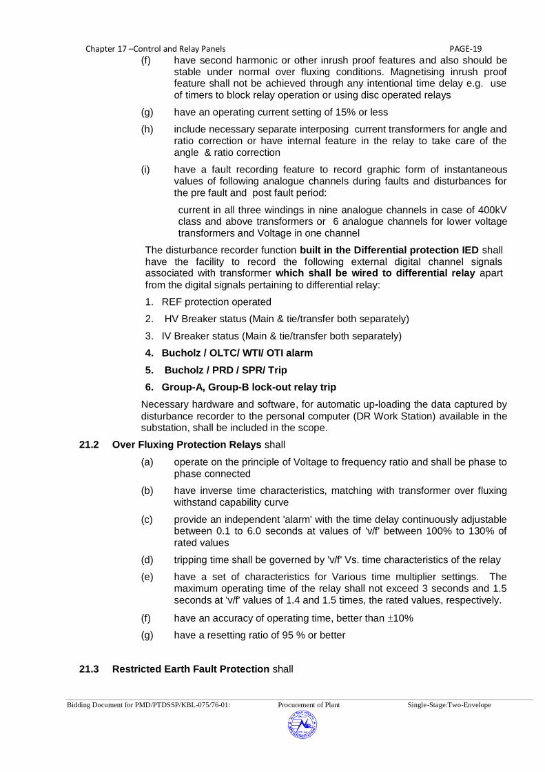
Chapter 17 –Control and Relay Panels PAGE-19
Bidding Document for PMD/PTDSSP/KBL-075/76-01: Procurement of Plant Single-Stage:Two-Envelope
(f) have second harmonic or other inrush proof features and also should be stable under normal over fluxing conditions. Magnetising inrush proof feature shall not be achieved through any intentional time delay e.g. use of timers to block relay operation or using disc operated relays
(g) have an operating current setting of 15% or less
(h) include necessary separate interposing current transformers for angle and ratio correction or have internal feature in the relay to take care of the angle & ratio correction
(i) have a fault recording feature to record graphic form of instantaneous values of following analogue channels during faults and disturbances for the pre fault and post fault period:
current in all three windings in nine analogue channels in case of 400kV class and above transformers or 6 analogue channels for lower voltage transformers and Voltage in one channel
The disturbance recorder function built in the Differential protection IED shall have the facility to record the following external digital channel signals associated with transformer which shall be wired to differential relay apart
from the digital signals pertaining to differential relay:
1. REF protection operated
2. HV Breaker status (Main & tie/transfer both separately)
3. IV Breaker status (Main & tie/transfer both separately)
4. Bucholz / OLTC/ WTI/ OTI alarm
5. Bucholz / PRD / SPR/ Trip
6. Group-A, Group-B lock-out relay trip
Necessary hardware and software, for automatic up-loading the data captured by
disturbance recorder to the personal computer (DR Work Station) available in the substation, shall be included in the scope.
21.2 Over Fluxing Protection Relays shall
(a) operate on the principle of Voltage to frequency ratio and shall be phase to phase connected
(b) have inverse time characteristics, matching with transformer over fluxing withstand capability curve
(c) provide an independent 'alarm' with the time delay continuously adjustable between 0.1 to 6.0 seconds at values of 'v/f' between 100% to 130% of rated values
(d) tripping time shall be governed by 'v/f' Vs. time characteristics of the relay
(e) have a set of characteristics for Various time multiplier settings. The maximum operating time of the relay shall not exceed 3 seconds and 1.5 seconds at 'v/f' values of 1.4 and 1.5 times, the rated values, respectively.
(f) have an accuracy of operating time, better than 10%
(g) have a resetting ratio of 95 % or better
21.3 Restricted Earth Fault Protection shall

Chapter 17 –Control and Relay Panels PAGE-20
Bidding Document for PMD/PTDSSP/KBL-075/76-01: Procurement of Plant Single-Stage:Two-Envelope
(a) be single pole type
(b) be of current/voltage operated type
(c) have a current setting range of 10-40% of 1 Amp./ have a suitable voltage setting range
(d) be tuned to the system frequency
(e) be phase segregated type for 1-ph transformer units
21.4 Back-up Over Current and Earth fault protection scheme with high set feature
(a) Shall have three over current and one earth fault element(s) which shall be either independent or composite unit(s).
(b) The scheme shall include necessary VT fuse failure relays for alarm purposes
(c) Over current relay shall
have directional IDMT characteristic with a definite minimum time of 3.0 seconds at 10 times setting and have a variable setting range of 50-200% of rated current
have low transient, over reach high set instantaneous unit of continuously variable setting range 500-2000 % of rated current
have a characteristic angle of 30/45 degree lead
include hand reset flag indicators or LEDs.
(d) Earth fault relay shall
have directional IDMT characteristic with a definite minimum time of 3.0 seconds at 10 times setting and have a variable setting range of 20-80% of rated current
have low transient, over reach high set instantaneous unit of continuously variable setting range 200-800 % of rated current
have a characteristic angle of 45/60 degree lag
include hand reset flag indicators or LEDs
include necessary separate interposing voltage transformers or have internal feature in the relay for open delta voltage to the relay
21.5 Transformer Overload Protection Relay shall
(a) be of single pole type
(b) be of definite time over-current type
(c) have one set of over-current relay element, with continuously adjustable setting range of 50-200% of rated current
(d) have one adjustable time delay relay for alarm having setting range of 1 to 10.0 seconds, continuously.
(e) have a drop-off/pick-up ratio greater than 95%.
21.6 Transformer Neutral Current Protection relay (for 1-Phase transformer bank neutral)
shall

Chapter 17 –Control and Relay Panels PAGE-21
Bidding Document for PMD/PTDSSP/KBL-075/76-01: Procurement of Plant Single-Stage:Two-Envelope
(a) have directional IDMT characteristic with a definite minimum time of 3.0 seconds at 10 times setting and have a variable setting range of 20-80% of rated current
21.7 Further, Transformer auxiliary protections contacts (Buchholz, PRD, SPRD, Oil Temperature, Winding Temperature, OLTC Buchholz etc.) can be wired suitably in above protections or provide separate Flag relays/Auxiliary relays as per scheme requirements. Further, transformer protections shall be grouped such that Differential trip, Buchholz-I trip, Oil temperature alarm and Winding temperature trip are on DC source-A while REF trip, Buchholz alarm, PRD-I trip, winding temperature alarm and Oil temperature trip are on DC source-B. In case multiple trip contacts for Buchholz relay / PRD relays are available, then their contacts shall be wired to both Group of Protection.
22 TEE DIFFERENTIAL PROTECTION RELAYS (If Applicable)
22.1 TEE-1 Differential protection relay shall
(a) be triple pole type
(b) have an operating time less than 30 milliseconds at 5 times the rated current
(c) have three instantaneous high set over current units
(d) have an adjustable bias setting range of 20-50%
(e) have an operating current setting of 15% of 1 Amp or less
22.2 TEE-2 Differential Protection relay shall
(a) be triple pole type
(b) have operating time less than 25 milliseconds at 5 times setting
(c) be tuned to system frequency
(d) have current setting range of 20 to 80% of 1 Amp
(e) be voltage operated, high impedance type
(f) be stable for all external faults
(g) be provided with suitable non linear resistors across the relay to limit the peak voltage to 1000 volts
23 TRIP CIRCUIT SUPERVISION RELAY
(a) The relay shall be capable of monitoring the healthiness of each 'phase' trip-coil and associated circuit of circuit breaker during 'ON' and 'OFF' conditions.
(b) The relay shall have adequate contacts for providing connection to alarm and event logger.
(c) The relay shall have time delay on drop-off of not less than 200 milli seconds and be provided with operation indications for each phase
24 TRIPPING RELAY

Chapter 17 –Control and Relay Panels PAGE-22
Bidding Document for PMD/PTDSSP/KBL-075/76-01: Procurement of Plant Single-Stage:Two-Envelope
High Speed Tripping Relay shall
(a) be instantaneous (operating time not to exceed 10 milli-seconds).
(b) reset within 20 milli seconds
(c) be D.C. operated
(d) have adequate contacts to meet the requirement of scheme, other functions like auto-reclose relay, LBB relay as well as cater to associated equipment like event logger(SAS), Disturbance recorder, fault Locator, etc.
(e) be provided with operation indicators for each element/coil.
25 DC SUPPLY SUPERIVISION RELAY
(a) The relay shall be capable of monitoring the failure of D.C. supply to which, it is connected.
(b) It shall have adequate potential free contacts to meet the scheme requirement.
(c) The relay shall have a 'time delay on drop-off' of not less than 100 milli seconds and be provided with operation indicator/flag.
26 BUS BAR PROTECTION
26.1 Redundant (1+1) numerical Bus Bar protection scheme for each Main bus (Bus1 /
Bus2) & Transfer Bus (as applicable) for 400kV shall be provided. Single bus bar protection scheme shall be provided for each main bus and transfer bus (as applicable) for 220KV and 132 KV voltage levels.
26.2 Each Bus Bar protection scheme shall
(a) have maximum operating time up to trip impulse to trip relay for all types of faults of 25 milli seconds at 5 times setting value.
(b) operate selectively for each bus bar
(c) give hundred percent security up to 63 KA fault level for 400KV/220KV and 31.5 KA for 132 KV
(d) incorporate continuous supervision for CT secondary against any possible open circuit and if it occurs, shall render the relevant zone of protection inoperative and initiate an alarm
(e) not give false operation during normal load flow in bus bars
(f) incorporate clear zone indication
(g) be of phase segregated and triple pole type
(h) provide independent zones of protection (including transfer bus if any). If the bus section is provided then each side of bus section shall have separate set of bus bar protection schemes
(i) include individual high speed electrically reset tripping relays for each feeder. However, in case of distributed Bus bar protection, individual trip relay shall not be required if bay unit is having trip duty contacts for breaker tripping.
(j) be transient free in operation
(k) include continuous D.C. supplies supervision
(l) not cause tripping for the differential current below the load current of

Chapter 17 –Control and Relay Panels PAGE-23
Bidding Document for PMD/PTDSSP/KBL-075/76-01: Procurement of Plant Single-Stage:Two-Envelope
heaviest loaded feeder. Contractor shall submit application check for the same.
(m) shall include necessary C.T. switching relays wherever C.T. switching is involved and have 'CT' selection incomplete alarm
(n) include protection 'IN/OUT' switch for each zone
(o) shall include trip relays, CT switching relays (if applicable), auxiliary CTs (if applicable) as well as additional power supply modules, input modules etc. as may be required to provide a Bus-bar protection scheme for the complete bus arrangement i.e. for all the bays or breakers including future bays as per the Single line diagram for new substations. However for extension of bus bar protection scheme in existing substations, scope shall be limited to the bay or breakers covered under this specification. Suitable panels (if required) to mount these are also included in the scope of the work.
(p) In case of distributed Bus bar Protection, the bay units for future bays may be installed in a separate panel and the same shall be located in switchyard panel room where bus bar protection panel shall be installed.
26.3 Built-in Local Breaker Backup protection feature as a part of bus bar protection scheme shall also be acceptable.
26.4 At existing substations, Bus-bar protection scheme with independent zones for each bus, will be available. All necessary co-ordination for 'AC' and 'DC' interconnections between existing schemes (Panels) and the bays proposed under the scope of this contract shall be fully covered by the bidder. Any auxiliary relay, trip relay, flag relay and multi tap auxiliary CTs (in case of biased differential protection) required to facilitate the operation of the bays covered under this contract shall be fully covered in the scope of the bidder.
26.5 The test terminal blocks (TTB) to be provided shall be fully enclosed with removable covers and made of moulded, non-inflammable plastic material with boxes and barriers moulded integrally. All terminals shall be clearly marked with identification numbers or letters to facilitate connection to external wiring. Terminal block shall have shorting, disconnecting and testing facilities for CT circuits.
27 WEATHER PROOF RELAY PANELS (If Applicable)
(a) This panel shall include necessary number of electrically reset relays each with at least eight contacts for isolator auxiliary contacts multiplication and for changing the CT and DC circuits to relevant zones of bus bar protection.
(b) The panel shall be sheet steel enclosed and shall be dust, weather and vermin proof. Sheet steel used shall be at least 2.0 mm thick and properly braced to prevent wobbling.
(c) The enclosures of the panel shall provide a degree of protection of not less than IP-55 (as per IEC-60529).
(d) The panel shall be of free standing floor mounting type or pedestal mounting type as per requirement.
(e) The panel shall be provided with double hinged doors with padlocking arrangement.

Chapter 17 –Control and Relay Panels PAGE-24
Bidding Document for PMD/PTDSSP/KBL-075/76-01: Procurement of Plant Single-Stage:Two-Envelope
(f) All doors, removable covers and panels shall be gasketed all around with synthetic gaskets Neoprene/EPDM. However, XLPE gaskets can also be used for fixing protective glass doors. Ventilating louvers, if provided shall have screens and filters. The screens shall be made of either brass or GI wire mesh
(g) Cable entries shall be from bottom. Suitable removable cable gland plate shall be provided on the cabinet for this purpose.
(h) All sheet steel work shall be degreased, pickled, phosphated and then applied with two coats of zinc chromates primer and two coats of finishing synthetic enamel paint, both inside and outside. The colour of the finishing paint shall be light grey.
(i) Suitable heaters shall be mounted in the panel to prevent condensation. Heaters shall be controlled by thermostats so that the cubicle
temperature does not exceed 30oC. On-off switch and fuse shall be provided. Heater shall be suitable for 230V AC supply Voltage.
(j) The test terminal blocks (TTB) to be provided shall be fully enclosed with removable covers and made of moulded, non-inflammable plastic material with boxes and barriers moulded integrally. All terminals shall be clearly marked with identification numbers or letters to facilitate connection to external wiring. Terminal block shall have shorting, disconnecting and testing facilities for CT circuits.
28 FAULT RECORDER
28.1.1 The fault recorder shall be provided for transmission line and the fault recorder as in-built feature of line distance relay is also acceptable provided the requirements of following clauses are met.
28.2 Fault recorder shall be microprocessor based and shall be used to record the graphic form of instantaneous values of voltage and current in all three phases, open delta voltage & neutral current, open or closed position of relay contacts and breakers during the system disturbances.
28.3 The Fault recorder shall consist of individual acquisition units, one for each feeder and an Evaluation unit which is common for the entire Substation. Whenever, more than one acquisition units are connected to an Evaluation unit, necessary hardware and software shall also be supplied for on line transfer of data from all acquisition units to Evaluation unit.
28.4 The acquisition unit is connected with evaluation unit being supplied as described in chapter 17 sub-station automation through bus conforming to IEC 61850. In case of extension sub-station which is equipped with Sub-station Automation System based on IEC 61850, one set of evaluation software shall be supplied and loaded in existing fault recorder evaluation unit. Automatic uploading of disturbance files from acquisition unit to evaluation unit shall be done through existing station bus only conforming to IEC 61850. Necessary configuration/updation including hardware if any shall be in the scope of the contractor.
28.4.1 In case of extension of existing substation(s) which are without sub-station automation system, one set of Evaluation unit shall be supplied for each substation where ever disturbance recorders are required to be supplied along with necessary evaluation software as specified above. The Evaluation unit shall consist of a desktop personal computer (including at least 17” TFT colour monitor, mouse and keyboard) and printer. The desktop PC shall have latest processor or better and having a clock speed 3.0GHz or better. The hard disk capacity of PC shall not be less than 300 GB and RAM

Chapter 17 –Control and Relay Panels PAGE-25
Bidding Document for PMD/PTDSSP/KBL-075/76-01: Procurement of Plant Single-Stage:Two-Envelope
capacity shall not be less than 3 GB. The evaluation unit hardware, for substations having SAS, shall be as described in clause no. 4.0 of chapter sub-station automation system.
28.5 Fault recorder shall have atleast 8 analogue and 16 digital channels for each feeder.
28.6 Acquisition units shall acquire the Disturbance data for the pre fault and post fault period and transfer them to Evaluation unit automatically to store in the hard disk. The acquisition units shall be located in the protection panels of the respective feeders.
28.7 The acquisition unit shall be suitable for inputs from current transformers with 1A rated secondary and capacitive voltage transformers with 63.5V (phase to neutral voltage) rated secondary. Any device required for processing of input signals in order to make the signals compatible to the Fault recorder equipment shall form an integral part of it. However, such processing of input signals shall in no way distort its waveform.
28.8 The equipment shall be carefully screened, shielded, earthed and protected as may be required for its safe functioning. Also, the Fault recorder shall have stable software, reliable hardware, simplicity of maintenance and immunity from the effects of the hostile environment of EHV switchyard which are prone to various interference signals typically from large switching transients.
28.9 Necessary software for transferring the data automatically from local evaluation unit to a remote station and receiving the same at the remote station through owner’s PLCC/VSAT/LEASED LINE shall be provided.
28.10 Evaluation software shall be provided for the analysis and evaluation of the recorded data made available in the PC under WINDOWS environment. The Software features shall include repositioning of analog and digital signals, selection and amplification of time and amplitude scales of each analogue and digital channel, calculation of MAX/MIN frequency, phase difference values, recording of MAX/MIN values etc. of analogue channel, group of signal to be drawn on the same axis etc, listing and numbering of all analogue and digital channels and current, voltage, frequency and phase difference values at the time of fault/tripping. Also, the software should be capable of carrying out Fourier /Harmonic analysis of the current and voltage wave forms. The Disturbance records shall also be available in COMTRADE format (IEEE standard- Common Format for Transient data Exchange for Power System)
28.11 The Evaluation unit shall be connected to the printer to obtain the graphic form of disturbances whenever desired by the operator.
28.12 Fault recorder acquisition units shall be suitable to operate from 220V DC or 110V DC as available at sub-station. Evaluation unit along with the printer shall normally be connected to 230V, single phase AC supply. In case of failure of AC supply, Evaluation unit and printer shall be switched automatically to the station DC through Inverter of adequate capacity which shall form a part of Fault recorder system. The inverter of adequate capacity shall be provided to cater the requirement specified in chapter sub-station automation clause no. 8.0 and DR evaluation unit.
28.13 The acquisition unit shall have the following features
(a) Facility shall exist to alarm operator in case of any internal faults in the acquisition units such as power supply fail, processor / memory fail etc and same shall be wired to annunciation system.
(b) The frequency response shall be 5 Hz on lower side and 250 Hz or better on upper side.
(c) Scan rate shall be 1000 Hz/channel or better.

Chapter 17 –Control and Relay Panels PAGE-26
Bidding Document for PMD/PTDSSP/KBL-075/76-01: Procurement of Plant Single-Stage:Two-Envelope
(d) Pre-fault time shall not be less than 100 milliseconds and the post fault time shall not be less than 2 seconds (adjustable). If another system fault occurs during one post-fault run time, the recorder shall also be able to record the same. However, the total memory of acquisition unit shall not be less than 5.0 seconds
(e) The open delta voltage and neutral current shall be derived either through software or externally by providing necessary auxiliary transformers.
(f) The acquisition unit shall be typically used to record at least the following digital channels :
1 Main CB R phase open
2 Main CB Y phase open
3 Main CB B phase open
4 Tie/TBC CB R phase open
5 Tie/TBC CB Y phase open
6 Tie/TBC CB B phase open
7 Main-1 carrier received
8 Main-1 protection operated
9 Main/Tie /TBC Auto reclosed operated
10 Over Voltage -Stage-1 /2 operated
11 Reactor / Stub/TEE-1/2/UF protection operated
12 Direct Trip received
13 Main-2 carrier received
14 Main- 2/ Back Up protection operated
15 Bus bar protection operated
16 LBB operated of main /tie/TBC circuit breaker
(g) In case the Fault recorder is in-built part of line distance protection, above digital channels may be interfaced either externally or internally.
(h) The sequence of digital channels shall be as per above list and which shall be ensured by the contractor. Digital channels shall be named suitably for easy identification of signals in the fault recordings.
(i) Any digital signal can be programmed to act as trigger for the acquisition unit. Analog channels should have programmable threshold levels for triggers and selection for over or under levels should be possible.
28.13.1 The colour laser printer shall be provided which shall be compatible with the desktop PC and shall use Plain paper. The print out shall contain the Feeder identity, Date and time (in hour, minute and second up to 100th of a second), identity of trigger source and Graphic form of analogue and digital signals of all the channels. Two packets of A4 size paper (500 sheets in each packet) suitable for printer shall be
supplied.
28.13.2 Each Fault recorder shall have its own time generator and the clock of the time generator shall be such that the drift is limited to +0.5 seconds/day, if allowed to run

Chapter 17 –Control and Relay Panels PAGE-27
Bidding Document for PMD/PTDSSP/KBL-075/76-01: Procurement of Plant Single-Stage:Two-Envelope
without synchronisation. Further, Fault recorder shall have facility to synchronise its time generator from Time Synchronisation Equipment having output of following types
Voltage signal : (0-5V continuously settable, with 50m Sec. minimum pulse duration)
Potential free contact (Minimum pulse duration of 50 m Sec.)
IRIG-B
RS232C
SNTP
The recorder shall give annunciation in case of absence of synchronising within a specified time.
28.13.3 Substations where Time Synchronisation Equipment is not available, time generator of any one of the Fault recorders can be taken as master and time generators of other Fault recorders and Event loggers in that station shall be synchronised to follow the master.
29 DISTANCE TO FAULT LOCATOR shall
a) be electronic or microprocessor based type
b) be 'On-line' type
c) be suitable for breaker operating time of 2 cycles
d) have built-in display unit
e) the display shall be directly in percent of line length or kilometres without requiring any further calculations
f) have an accuracy of 3% or better for the typical conditions defined for operating timings measurement of distance relays
g) The above accuracy should not be impaired under the following conditions:
presence of remote end infeed
predominant D.C. component in fault current
high fault arc resistance
severe CVT transients
h) shall have mutual zero sequence compensation unit if fault locator is to be used on double circuit transmission line
i) built in feature of line distance relay is acceptable provided the requirements of above clauses are met
30 TIME SYNCHRONISATION EQUPMENT
30.1.1 The Time synchronisation equipment shall receive the co-ordinated Universal Time (UTC) transmitted through Geo Positioning Satellite System (GPS) and synchronise equipments to the Nepal Standard Time in a substation.
30.1.2 Time synchronisation equipment shall include antenna, all special cables and processing equipment etc.
30.1.3 It shall be compatible for synchronisation of Event Loggers, Disturbance recorders and SCADA at a substation through individual port or through Ethernet realised through optic fibre bus.

Chapter 17 –Control and Relay Panels PAGE-28
Bidding Document for PMD/PTDSSP/KBL-075/76-01: Procurement of Plant Single-Stage:Two-Envelope
30.1.4 Equipment shall operate up to the ambient temperature of 50 degree centigrade and 80% humidity.
30.1.5 The synchronisation equipment shall have 2 micro-second accuracy. Equipment shall give real time corresponding to IST (taking into consideration all factors like voltage, & temperature variations, propagation & processing delays etc).
30.2 Equipment shall meet the requirement of IEC 60255 for storage & operation.
30.2.1 The system shall be able to track the satellites to ensure no interruption of synchronisation signal.
30.2.2 The output signal from each port shall be programmable at site for either one hour, half hour, minute or second pulse, as per requirement.
30.2.3 The equipment offered shall have six (6) output ports. Various combinations of output ports shall be selected by the customer, during detailed engineering, from the following :
Potential free contact (Minimum pulse duration of 50 milli Seconds.)
IRIG-B
RS232C
SNTP Port
30.2.4 The equipment shall have a periodic time correction facility of one second periodicity.
30.2.5 Time synchronisation equipment shall be suitable to operate from 220V DC or 110V DC as available at Substation.
30.2.6 Equipment shall have real time digital display in hour, minute, second (24 hour mode) & have a separate time display unit to be mounted on the top of control panels having display size of approx. 100 mm height.
31 RELAY TEST KIT
31.1.1 One relay test kit shall comprise of the following equipment as detailed here under
3 sets Relay tools kits
2 nos. Test plugs for TTB
2 nos. Test plugs for using with modular type relays (if applicable)
32 TYPE TESTS
32.1.1 The reports for following type tests shall be submitted during detailed engineering for the Protective relays, Fault Recorder, Fault locator and Disturbance recorder:
a) Insulation tests as per IEC 60255-5
b) DC Voltage dips and interruptions/Variation as per IEC 6100-4-29.
c) High frequency disturbance test as per IEC 61000-4 16, Class IV (Not applicable for electromechanical relays)
d) Electrostatic discharges as per IEC 61000-4-2, level; 4 (not applicable for Electromechanical relays)
e) Fast transient test as per IEC 61000, Level IV (Not applicable for electromechanical relays)

Chapter 17 –Control and Relay Panels PAGE-29
Bidding Document for PMD/PTDSSP/KBL-075/76-01: Procurement of Plant Single-Stage:Two-Envelope
f) Relay characteristics, performance and accuracy test as per IEC 60255
Steady state Characteristics and operating time
Dynamic Characteristics and operating time for distance protection relays and current differential protection relays
Conformance test as per IEC 61850-10.
For Fault recorder, Disturbance recorder; only performance tests are intended under this item.
g) Tests for thermal and mechanical requirements as per IEC 60255-6
h) Tests for rated burden as per IEC 60255-6
i) Contact performance test as per IEC 60255-0-20 (not applicable for Distance to fault locator and Disturbance recorder)
In case there is a change either in version or in model (Except firmware) of the relay, the contractor has to submit the type test reports for the offered revision/model.
32.2 Steady state & Dynamic characteristics test reports on the distance protection relays, as type test, shall be based on test programme specified in Appendix A on simulator/network analyser/PTL. Alternatively, the files generated using Electromagnetic transient Programme (EMTP) can also be used for carrying out the above tests. Single source dynamic tests on transformer differential relay shall be/ should have been conducted based on general guidelines specified in CIGRE committee 34 report on Evaluation of characteristics and performance of Power system protection relays and protective systems.
33 CONFIGURATION OF RELAY AND PROTECTION PANELS
The following is the general criteria for the selection of the equipments to be provided in each type of panel. However, contractor can optimise the requirement of panels by suitably clubbing the feeder protection and CB relay panels. It may be noted that Main-I and Main-II protections for line can not be provided in single panel. Similarly, Group-I & Group-II protections for transformer can not be provided in single panel.
CONTROL PANEL
Various types of control panels shall consist of the following
a Ammeter 3 set for each Line, BC, TBC Bus section, Bus Reactor and Transformer
b Ammeter with Selector switch 1 set for each line reactor c Wattmeter with transducer 1 set for each line, transformer d Varmeter with transducer 1 set for each line,transformer,Bus reactor e Varmeter with transducer 1 set for each Line Reactor f CB Control switch 1 no. for each Circuit breaker
g Isolator Control switch 1 no. for each isolator

Chapter 17 –Control and Relay Panels PAGE-30
Bidding Document for PMD/PTDSSP/KBL-075/76-01: Procurement of Plant Single-Stage:Two-Envelope
h Semaphore 1 no. for each earth switch i Red indicating lamp 1 no. for each Circuit breaker
j Red indicating lamp 1 no. for each isolator k Green indicating lamp 1 no. for each Circuit breaker
l Green indicating lamp 1 no. for each isolator m White indicating lamp 2 nos for each feeder
(DC healthy lamp) n Annunciation windows with 18 nos for each feeder
associated annunciation relays o Push button for alarm 3 nos for each control panel
Accept/reset/lamp test p Synchronising Socket 1 no. for each Circuit Breaker if required q Synchronising selector Switch 1 no. for each Circuit Breaker switch if
required r Protection Transfer Switch 1 no. for each breaker in case of
DMT /DM*/SMT scheme(Except TBC And BC Breaker)-*with Bypass ISO s Mimic to represent SLD Lot in all control panels
t Voltmeter with selector 1 no for each line, transformer , bus
Switch reactor
u Cut out, mounting and Lot for transformers/reactors wiring for RWTI and selector switch
Notes:
1 For transformer feeders, all equipments of control panel shall be provided separately for HV and MV sides.
2. In case of incomplete diameter (D and I type layouts), control panel shall be equipped fully as if the diameter is complete, unless otherwise specified. Annunciation relays shall also be provided for the same and if required, necessary panel shall be supplied to accommodate the same.
3. The above list of equipments mentioned for control panel is generally applicable unless it is defined elsewhere and in case of bay extension in existing substations, necessary equipments for matching the existing control panel shall be supplied.
4. Common synchronising switch is also acceptable in Synchronising trolley for new Substations. In this case. individual synchronising selector switch is not required for each Circuit Breaker in control panel
5. Each line /HV side of transformer/MV/LV side of transformer /Bus reactor /TBC /BC/ Bus Section shall be considered as one feeder for above purpose.

Chapter 17 –Control and Relay Panels PAGE-31
Bidding Document for PMD/PTDSSP/KBL-075/76-01: Procurement of Plant Single-Stage:Two-Envelope
33.1.1.1.1.1 LINE PROTECTION PANEL (400/220)
The Line Protection panel for transmission lines shall consist of following protection features/schemes
Sl. No. Description 220kV 400kV
1. Main-1 Numerical Distance protection scheme
1 Set 1 Set
2. Main-2 Numerical Distance protection scheme
1 Set 1 Set
3. Over Voltage Protection Scheme
NIL 1 Set
4. Fault Recorder 1 Set 1 Set
5. Distance to fault Locator 1 Set 1 Set
6. 3 Phase Trip Relays 2 Nos. 2 Nos.
7. Flag relays, carrier receive relays, aux. Relays, timers etc as per scheme requirements
As required
As required
8. Under Voltage protection relay for isolator/earth switch Interlock
2 Nos 2 Nos
9. . Cut-out and wiring with TTB for energy meter
1 Set 1 Set
10. Directional Back up Over current and E/F protection scheme
NIL NIL
In a substation where 400KV/220 KV lines are under the scope of the contract, bidder is required to give identical Main-1 and Main-2 distance protection schemes for all voltage levels.
33.1.1.1.1.2 TRANSFORMER PROTECTION PANEL
The protection panel for Auto transformer/Transformer shall consists of the following features/schemes:

Chapter 17 –Control and Relay Panels PAGE-32
Bidding Document for PMD/PTDSSP/KBL-075/76-01: Procurement of Plant Single-Stage:Two-Envelope
S. No.
Description HV side
MV/LV side
1. Transformer Differential Protection scheme 1 Nos. Nil
2. Restricted Earth fault protection scheme 1 no. 1 no@
@ Not applicable for auto-transformer
3. Directional back up O/C and E/F relay with non directional high set feature
1 set 1 set
4. Over Fluxing Protection scheme 1 no. 1 no.$
$ Applicable only for 400/220kV X’former
5. Overload protection scheme 1 nos. NIL
6. Three phase trip relays 2 nos. 2 nos.
7. CVT selection relays as per scheme requirement Lot Lot
8. Cut-out and wiring with TTB for energy meter 1 set 1 set
9. Transformer Neutral Current relay for 1-Phase transformer bank
1 Set
10. Flag Relays/Aux. Relays for wiring Transformer auxiliary protection contacts such as Buchholz, Oil Temperature, Winding Temperature, PRV, SPRD OLTC Buchholz etc. as per scheme requirements
As required
The above protection schemes may be clubbed in Group-I/II as per clause no. 21 of technical specification.
33.1.1.1.1.3 REACTOR PROTECTION PANEL
The protection panel for Reactor shall consist of the following protection features/schemes:
Sl. No.
Description Qty.
1. Reactor Differential Protection scheme 1 no.
2. Restricted Earth fault Protection scheme 1 no.
3. Reactor back up impedance protection scheme 1 set
4. Three phase trip relays 2 nos.
5. CVT selection relay as per scheme requirement
Lot
6. Flag Relays/Aux. Relays for wiring Reactor auxiliary protection contacts such as Buchholz, Oil Temperature, Winding Temperature, PRV,SPRD etc. as per scheme requirements
As required
33.1.1.1.1.4 BREAKER RELAY PANEL (400KV, 220kV & 132kV)
The breaker relay panel shall comprise of the following:
Sl. No.
Description With A/R Without A/R

Chapter 17 –Control and Relay Panels PAGE-33
Bidding Document for PMD/PTDSSP/KBL-075/76-01: Procurement of Plant Single-Stage:Two-Envelope
1. Breaker failure Protection Scheme 1 No. 1 No.
2. DC supply Supervision relay 2 Nos. 2 Nos.
3. Trip Circuit supervision relays# 6 Nos. 6 Nos.
4. Auto-reclose scheme (if standalone)
1 Nos. NIL
5. Flag relays, aux relays, timers, trip relays as per scheme requirements
As required As required
# Trip supervision relays shall be 2 or 6 numbers as per no. of trip coils for each 132KV Circuit breaker
Note: Equipment/relays to be provided under CB Relay Panel may be accommodated in the Protection Panels to be provided for Transmission Line/Transformer/Reactor as applicable.
34 ERECTION AND MAINTENANCE TOOL EQUIPMENTS
All special testing equipment required for the installation and maintenance of the apparatus, instruments devices shall be furnished in relevant schedule
35 TROPICALISATION
Control room will be normally air-cooled/air- conditioned. All equipments shall however be suitable for installation in a tropical monsoon area having hot, humid climate and dry and dusty seasons with ambient conditions specified in the specification. All control wiring, equipment and accessories shall be protected against fungus growth, condensation, vermin and other harmful effects due to tropical environment.

Chapter 17 –Control and Relay Panels PAGE-38
Bidding Document for PMD/PTDSSP/KBL-075/76-01: Procurement of Plant Single-Stage:Two-Envelope
APPENDIX-A
Test programme for distance relays
General Comments:
1. These test cases are evolved from the report of working group 04 of study committee 34 (Protection) on evaluation of characteristics and performance of power system protection relays and protective systems. For any further guidelines required for carrying out the tests, reference may be made to the above document.
2. The test shall be carried out using network configuration and system parameters as shown in the figure-1
3. All denotations regarding fault location, breakers etc are referred in figure –1
4. The fault inception angles are referred to R- N voltage for all types of faults
5. The fault inception angle is zero degree unless otherwise specified
6. Where not stated specifically, the fault resistance (Rf) shall be zero or minimum as possible in simulator
7. Single pole circuit breakers are to be used
8. The power flow in double source test is 500 MW
System parameters
System voltage =400KV
CTR= 1000/1
PTR = 400000/110 (with CVT, the parameters of CVT model are shown in figure –2)
Line parameters/km
Positive Sequence Resistance, (r1) = 0. 02897 Ω Positive Sequence Reactance (x1) = 0.3072 Ω Zero Sequence Resistance (r0) = 0.2597 Ω Zero Sequence Reactance (x1) = 1.0223 Ω Zero Sequence Mutual Resistance (rm) = 0.2281 Ω Zero Sequence Mutual Reactance (xm) = 0.6221 Ω Zero Sequence succeptance (bo) = 2.347 µ mho
Positive Sequence succeptance (b1) =3.630 µ mho
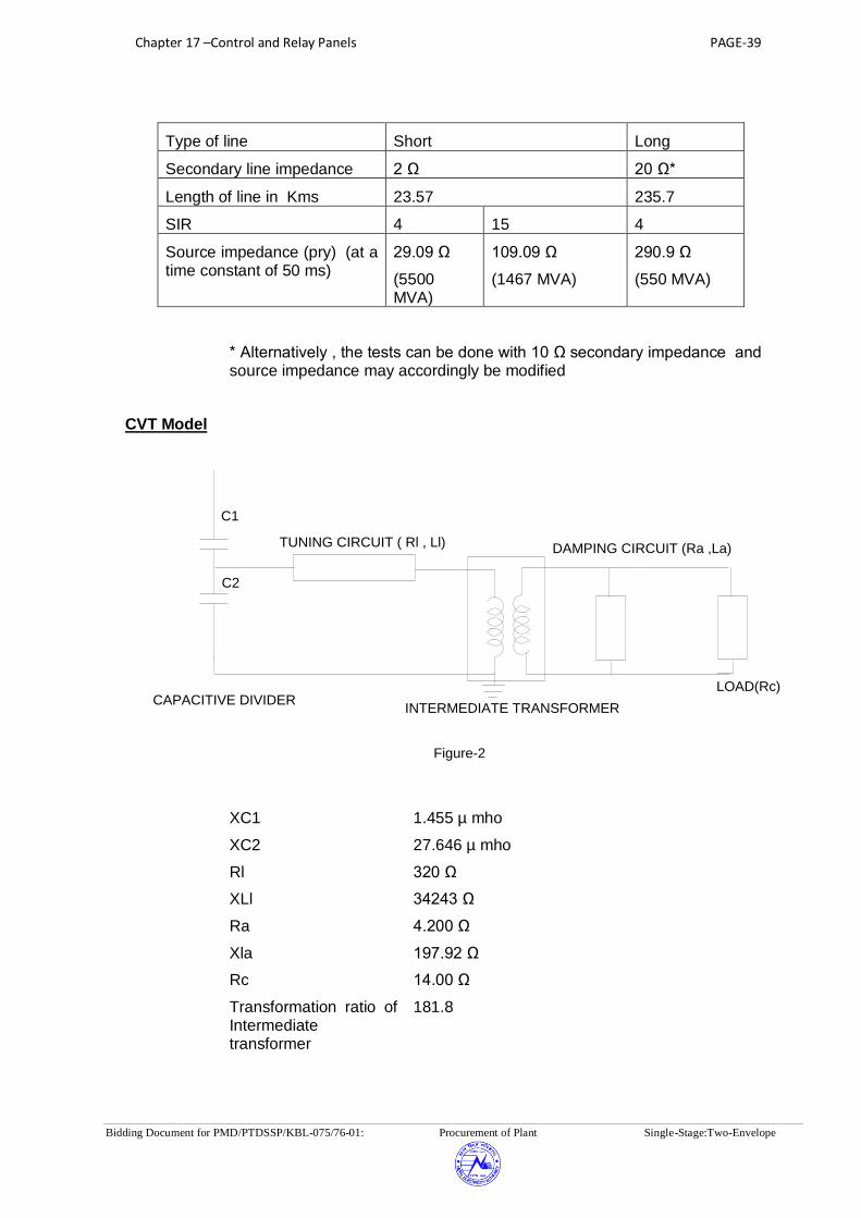
Chapter 17 –Control and Relay Panels PAGE-39
Bidding Document for PMD/PTDSSP/KBL-075/76-01: Procurement of Plant Single-Stage:Two-Envelope
Type of line Short Long
Secondary line impedance 2 Ω 20 Ω*
Length of line in Kms 23.57 235.7
SIR 4 15 4
Source impedance (pry) (at a time constant of 50 ms)
29.09 Ω
(5500 MVA)
109.09 Ω
(1467 MVA)
290.9 Ω
(550 MVA)
* Alternatively , the tests can be done with 10 Ω secondary impedance and source impedance may accordingly be modified
CVT Model
INTERMEDIATE TRANSFORMER
TUNING CIRCUIT ( Rl , Ll) DAMPING CIRCUIT (Ra ,La)
LOAD(Rc)
C1
C2
CAPACITIVE DIVIDER
Figure-2
XC1 1.455 µ mho
XC2 27.646 µ mho
Rl 320 Ω
XLl 34243 Ω
Ra 4.200 Ω
Xla 197.92 Ω
Rc 14.00 Ω
Transformation ratio of Intermediate transformer
181.8

Chapter 17 –Control and Relay Panels PAGE-40
Bidding Document for PMD/PTDSSP/KBL-075/76-01: Procurement of Plant Single-Stage:Two-Envelope
Details of fault cases to be done
SN Description Single source with short line
(2 )
Single source long
line (20 )
Double source with short double line
(2 )
Double source with long single line (20
)
CLOSE C1, OPEN C2,C3,C4 CLOSE C1, OPEN C2,C3,C4
CLOSE C1, C2,C3,C4
CLOSE C1,C3
OPEN C2,C4
SIR=4 SIR=15 SIR =4
SIR = 4 SIR=4
1 Dynamic accuracy for zone 1
Tests to be done at 2 locations ( 84 % and 76 % of line length ) X 4 faults (RN , YB, YBN, RYB) X 2 fault inception angle
(0°, 90°)= 16 cases
Tests to be done at 2 locations ( 84 % and 76 % of line length ) X 4 faults (RN , YB, YBN, RYB) X 2 fault inception angle (0°,90°)= 16 cases
Tests to be done at 2 locations ( 84 % and 76 % of line length ) X 4 faults (RN , YB, YBN, RYB) X 2 fault inception angle (0°,90°)= 16 cases
Tests to be done at 2 locations (84% and 76% of line length) X 4 faults (RN , YB, YBN, RYB) X 2 fault inception angle
(0°, 90°)= 16 cases
2 Operating time for zone 1 at SIR =4
Tests to be done at 3 locations (0% , 40% and 64% of line length ) X 4 faults (RN, YB, YBN, RYB) X 4 fault inception angle
(0°, 30°,60° and 90°) = 48 cases
Tests to be done at 3 locations (0 % , 40 % and 64 % of line length ) X 4 faults (RN , YB, YBN, RYB) X 4 fault inception angle
(0°,30°,60°and 90°)= 48 cases
Tests to be done at 3 locations ( 0 % , 40 % and 64 % of line length ) X 4 faults (RN , YB, YBN, RYB) X 4 fault inception angle
(0°, 30°,60° and 90°)= 48 cases
Tests to be done at 1 location (40 % of line length) X 4 faults (RN, YB, YBN, RYB) X 4 fault inception angle
(0°,30°,60° and 90 °)= 16 cases
Tests to be done at 1 location (40 % of line length ) X 4 faults (RN, YB, YBN, RYB) X 4 fault inception angle (0°,30°,60° and 90°)= 16cases
3 Operating time for zone II and Zone III
Tests to be done at 1 location ( 100 % of line length ) X 1 faults (RN, YB, YBN, RYB) X 2 zones (II and
Tests to be done at 1 location (100 % of line length) X 1 faults (RN , YB, YBN, RYB) X 2 zones (II and
Tests to be done at 1 location (100 % of line length ) X 1 faults (RN , YB, YBN, RYB) X 2 Zones (II and

Chapter 17 –Control and Relay Panels PAGE-41
Bidding Document for PMD/PTDSSP/KBL-075/76-01: Procurement of Plant Single-Stage:Two-Envelope
SN Description Single source with short line
(2 )
Single source long
line (20 )
Double source with short double line
(2 )
Double source with long single line (20
)
III) = 2 cases III) = 2 cases III) = 2 cases
4 Switch on to fault feature
Tests to be done at 2 location ( 0 % and 32 %) X 1 faults (RYB) Any fault inception angle = 2 cases
5 Operation during current reversal
Tests to be done at 2 location (0 % and 80 % of line length ) X 1 faults ( RN) X 1 fault inception angle (0 degrees) = 2 cases
CLOSE C1, OPEN C2,C3,C4 CLOSE C1, OPEN C2,C3,C4
CLOSE C1, C2,C3,C4
CLOSE C1,C3
OPEN C2,C4
SIR=4 SIR=15 SIR =4
SIR = 4 SIR=4
6 Operation at simultaneous faults
Tests to be done at 2 location (8 % and 64 % of line length ) X 2 faults ( RN in circuit 1 to BN in circuit 2 and RN in circuit 1 to RYN in circuit 2 in 10 ms) X 1 fault inception angle ( 0 °) = 4 cases (*1)
7 Directional sensitivity
Tests to be done at 1

Chapter 17 –Control and Relay Panels PAGE-42
Bidding Document for PMD/PTDSSP/KBL-075/76-01: Procurement of Plant Single-Stage:Two-Envelope
SN Description Single source with short line
(2 )
Single source long
line (20 )
Double source with short double line
(2 )
Double source with long single line (20
)
location (0% reverse) X 6 faults ( RN ,YB, YBN , RYB,RN with Rf=13.75 ohm(sec) and RYN with Rf= 13.75 Ohm (sec) X 2 fault inception angle (0° ,90° ) = 12cases
8 Limit for fault resistance
Tests to be done at 2 location ( 0% and 68 % of line length) X 1 fault ( RN with Rf=13.75 ohm(sec) X 2 fault inception angle (0°,90° ) = 4 cases
9 Operation at evolving faults
Tests to be done at 2 location (32 % and 0% of line length) X 2 faults (RN to RYN) x in 2 timings (10 ms and 30 ms) X 2 load direction (from A to B and from B to A) = 16 cases
9
Fault locator function , in case the same is offered as built in feature
Measure fault location for all cases under 1 and 2
Measure fault location for all cases under 1 and 2
Measure fault location for all cases under 1 and 2
Measure fault location for all cases under 2 and 6
Measure fault location for all cases under 2, 7 and 9

Chapter 17 –Control and Relay Panels PAGE-43
Bidding Document for PMD/PTDSSP/KBL-075/76-01: Procurement of Plant Single-Stage:Two-Envelope
APPENDIX-B
Terminal Block (TB) Nomenclature for Relay & interface panels
TB for external TB for Interpanel
Circuit type connections connections
CT X:CT XI:CT
PT X:VT XI:VT
AC Auxiliary X:AC XI:AC
DC Auxiliary X:DC XI:DC
Trip Circuit 1 X:TC1 XI:TC1
Trip Circuit 2 X:TC2 XI:TC2
LBB & BB X:LBB XI:LBB
CB X:CB/X:CBT XI:X
ISOLATOR X:ISA/ISB/ISL/ISR XI:X
EARTH SWITCH X:ES XI:X
PROTECTION COUPLER X:PC XI:PC
ENERGY METER X:EM ---
Reactor X:SR XI:SR
Transformer X:AT XI:AT
Others Control & status signals X:X XI:X
Feeder relay Panels designation:
Typical Bay / Busbar Panel Ref. 400kV Bay no. 1 (401) 4R1A, 4R1B and so on 220kV Bay no. 1 (201) 2R1A, 2R1B and so on 132kV Bay no. 1 (101) 1R1A, 1R1B and so on Bus 400kV 4BB1, 4BB2 and so on
Bus220kV 2BB1, 2BB2 and so on
Bus132kV 1BB1, 1BB2 and so on
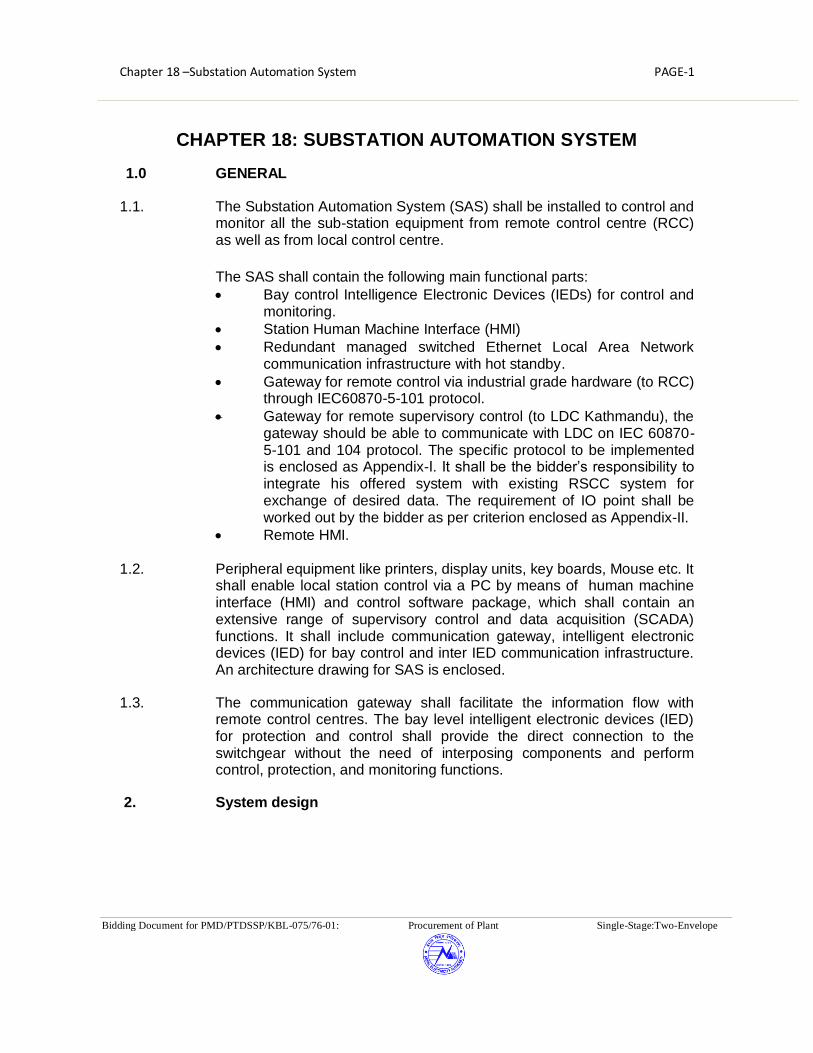
Chapter 18 –Substation Automation System PAGE-1
Bidding Document for PMD/PTDSSP/KBL-075/76-01: Procurement of Plant Single-Stage:Two-Envelope
CHAPTER 18: SUBSTATION AUTOMATION SYSTEM
1.0 GENERAL
1.1. The Substation Automation System (SAS) shall be installed to control and monitor all the sub-station equipment from remote control centre (RCC) as well as from local control centre.
The SAS shall contain the following main functional parts:
Bay control Intelligence Electronic Devices (IEDs) for control and monitoring.
Station Human Machine Interface (HMI)
Redundant managed switched Ethernet Local Area Network communication infrastructure with hot standby.
Gateway for remote control via industrial grade hardware (to RCC) through IEC60870-5-101 protocol.
Gateway for remote supervisory control (to LDC Kathmandu), the gateway should be able to communicate with LDC on IEC 60870-5-101 and 104 protocol. The specific protocol to be implemented is enclosed as Appendix-I. It shall be the bidder’s responsibility to integrate his offered system with existing RSCC system for exchange of desired data. The requirement of IO point shall be worked out by the bidder as per criterion enclosed as Appendix-II.
Remote HMI.
1.2. Peripheral equipment like printers, display units, key boards, Mouse etc. It shall enable local station control via a PC by means of human machine interface (HMI) and control software package, which shall contain an extensive range of supervisory control and data acquisition (SCADA) functions. It shall include communication gateway, intelligent electronic devices (IED) for bay control and inter IED communication infrastructure. An architecture drawing for SAS is enclosed.
1.3. The communication gateway shall facilitate the information flow with remote control centres. The bay level intelligent electronic devices (IED) for protection and control shall provide the direct connection to the switchgear without the need of interposing components and perform control, protection, and monitoring functions.
2. System design

Chapter 18 –Substation Automation System PAGE-2
Bidding Document for PMD/PTDSSP/KBL-075/76-01: Procurement of Plant Single-Stage:Two-Envelope
2.1 General system design
The Substation Automation System (SAS) shall be suitable for operation and monitoring of the complete substation including future extensions as well as able to integrate to the existing SAS as given in Chapter 1 - PSR.
The systems shall be of the state-of-the art suitable for operation under electrical environment present in extra high voltage substations, follow the latest engineering practice, and ensure long-term compatibility requirements and continuity of equipment supply and the safety of the operating staff.
The offered SAS shall support remote control and monitoring from Remote Control centres via gateways.
The system shall be designed such that personnel without any background knowledge in Microprocessor-based technology are able to operate the system. The operator interface shall be intuitive such that operating personnel shall be able to operate the system easily after having received some basic training.
The system shall incorporate the control, monitoring and protection functions specified, self-monitoring, signalling and testing facilities, measuring as well as memory functions, event recording and evaluation of disturbance records.
Maintenance, modification or extension of components may not cause a shutdown of the whole substation automation system. Self-monitoring of components, modules and communication shall be incorporated to increase the availability and the reliability of the equipment and minimize maintenance.
Bidder shall offer the Bay level unit (a bay comprises of one circuit breaker and associated disconnector, earth switches and instrument transformer), bay mimic along with relay and protection panels and tele protection panels (described in other sections of technical specifications) housed in air-conditioned GIS Building and also in Switchyard Panel Room and integrate to the existing Station HMI system in Control Room building for overall optimisation in respect of cabling and control room building.
2.2 System architecture
The SAS shall be based on a decentralized architecture and on a concept of bay-oriented, distributed intelligence.
Functions shall be decentralized, object-oriented and located as close as possible to the process.

Chapter 18 –Substation Automation System PAGE-3
Bidding Document for PMD/PTDSSP/KBL-075/76-01: Procurement of Plant Single-Stage:Two-Envelope
The main process information of the station shall be stored in distributed databases. The typical SAS architecture shall be structured in two levels, i.e. in a station and a bay level.
At bay level, the IEDs shall provide all bay level functions regarding control, monitoring and protection, inputs for status indication and outputs for commands. The IEDs should be directly connected to the switchgear without any need for additional interposition or transducers.
Each bay control IED shall be independent from each other and its functioning shall not be affected by any fault occurring in any of the other bay control units of the station.
The data exchange between the electronic devices on bay and station level shall take place via the communication infrastructure. This shall be realized using fibre-optic cables, thereby guaranteeing disturbance free communication. The fibre optic cables shall be run in GI conduit pipes. Data exchange is to be realised using IEC 61850 protocol with a redundant managed switched Ethernet communication infrastructure
The communication shall be made in fault tolerant ring in redundant mode, excluding the links between individual bay IEDs to switch wherein the redundant connections are not envisaged, such that failure of one set of fiber shall not affect the normal operation of the SAS. However failure of fiber shall be alarmed in SAS. Each fiber optic cable shall have four (4) spare fibers
At station level, the entire station shall be controlled and supervised from the station HMI. It shall also be possible to control and monitor the bay from the bay level equipment at all times.
Clear control priorities shall prevent operation of a single switch at the same time from more than one of the various control levels, i.e. RCC, station HMI, bay level or apparatus level. The priority shall always be on the lowest enabled control level.
The station level contains the station-oriented functions, which cannot be realised at bay level, e.g. alarm list or event list related to the entire substation, gateway for the communication with remote control centres.
The GPS time synchronising signal (as specified in the section relay & protection) for the synchronization of the entire system shall be provided.
The SAS shall contain the functional parts as described in para 1.2 above.
2.3 FUNCTIONAL REQUIREMENTS
The high-voltage apparatus within the station shall be operated from different places:
Chapter 18 –Substation Automation System PAGE-4
Bidding Document for PMD/PTDSSP/KBL-075/76-01: Procurement of Plant Single-Stage:Two-Envelope
Remote control centres
Station HMI.
Local Bay controller IED (in the bays)
Operation shall be possible by only one operator at a time.
The operation shall depend on the conditions of other functions, such as interlocking, synchro check, etc. (see description in”Bay level control functions”).
2.3.1 Select-before-execute
For security reasons the command is always to be given in two stages: selection of the object and command for operation under all mode of operation except emergency operation. Final execution shall take place only when selection and command are actuated.
2.3.2 Command supervision
Bay/station interlocking and blocking
Software Interlocking is to be provided to ensure that inadvertent incorrect operation of switchgear causing damage and accidents in case of false operation does not take place.
In addition to software interlocking hardwired interlocking are to be provided for:
(a) Bus Earth switch Interlocking
(b) Transfer Bus interlocking (if applicable)
It shall be a simple layout, easy to test and simple to handle when upgrading the station with future bays. For software interlocking the bidder shall describe the scenario while an IED of another bay is switched off or fails.
A software interlock override function shall be provided which can be enabled to bypass the interlocking function.
2.3.3 Run Time Command cancellation
Command execution timer (configurable) must be available for each control level connection. If the control action is not completed within a specified time, the command should get cancelled.
2.3.4 Self-supervision
Continuous self-supervision function with self-diagnostic feature shall be included.

Chapter 18 –Substation Automation System PAGE-5
Bidding Document for PMD/PTDSSP/KBL-075/76-01: Procurement of Plant Single-Stage:Two-Envelope
2.3.5 User configuration
The monitoring, controlling and configuration of all input and output logical signals and binary inputs and relay outputs for all built-in functions and signals shall be possible both locally and remotely.
It shall also be possible to interconnect and derive input and output signals, logic functions, using built-In functions, complex voltage and currents, additional logics (AND-gates, OR gates and timers). (Multi-activation of these additional functions should be possible).
The Functional requirement shall be divided into following levels:
a. Bay (a bay comprises of one circuit breaker and associated disconnector, earth switches and instrument transformer) Level Functions
b. System Level Functions
3.1. Bay level functions
In a decentralized architecture the functionality shall be as close to the process as possible. In this respect, the following functions can be allocated at bay level:
Bay control functions including data collection functionality in bay control/protection unit.
Bay protection functions
Separate IEDs shall be provided for bay control function and bay protection function.
3.1.1. Bay control functions
3.1.1.1. Overview
Functions
Control mode selection Select-before-execute principle Command supervision:
o Interlocking and blocking o Double command
Synchrocheck, voltage selection Run Time Command cancellation Transformer tap changer control (Raise and lower of tap ) (for power
transformer bays) Operation counters for circuit breakers and pumps Hydraulic pump/ Air compressor runtime supervision Operating pressure supervision through digital contacts only

Chapter 18 –Substation Automation System PAGE-6
Bidding Document for PMD/PTDSSP/KBL-075/76-01: Procurement of Plant Single-Stage:Two-Envelope
Breaker position indication per phase Alarm annunciation Measurement display Local HMI (local guided, emergency mode) Interface to the station HMI. Data storage for at least 200 events Extension possibilities with additional I/O's inside the unit or via fibre-
optic communication and process bus
3.1.1.2. Control mode selection
Bay level Operation:
As soon as the operator receives the operation access at bay level the operation is normally performed via bay control IED. During normal operation bay control unit allows the safe operation of all switching devices via the bay control IED.
EMERGENCY Operation
It shall be possible to close or open the selected Circuit Breaker with ON or OFF push buttons even during the outage of bay IED.
REMOTE mode
Control authority in this mode is given to a higher level (Remote Control Centre) and the installation can be controlled only remotely. Control operation from lower levels shall not be possible in this operating mode.
3.1.1.3. Synchronism and energizing check
The synchronism and energizing check functions shall be bay-oriented and distributed to the bay control and/or protection devices. These features are:
Settable voltage, phase angle, and frequency difference.
Energizing for dead line - live bus, live line - dead bus or dead line – dead bus with no synchro-check function.
Synchronising between live line and live bus with synchro-check function
Voltage selection
The voltages relevant for the Synchro check functions are dependent on the station topology, i.e. on the positions of the circuit breakers and/or the isolators. The correct voltage for synchronizing and energizing is derived from the auxiliary switches of the circuit breakers,

Chapter 18 –Substation Automation System PAGE-7
Bidding Document for PMD/PTDSSP/KBL-075/76-01: Procurement of Plant Single-Stage:Two-Envelope
the isolator, and earthing switch and shall be selected automatically by the bay control and protection IEDs.
3.1.1.4. Transformer tap changer control
Raise and lower operation of OLTC taps of transformer shall be facilitated through Bay controller IED.
3.1.2. Bay protection functions
3.1.2.1. General
The protection functions are independent of bay control function. The protection shall be provided by separate protection IEDs (numerical relays) and other protection devices as per section Relay & Protection.
IEDs, shall be connected to the communication infrastructure for data sharing and meet the real-time communication requirements for automatic functions. The data presentation and the configuration of the various IEDs shall be compatible with the overall system communication and data exchange requirements.
Event and disturbance recording function
Each IED should contain an event recorder capable of storing at least 200 time-tagged events. The disturbance recorder function shall be as per detailed in Chapter 17 – Control, Relay & Protection Panels.
3.1.2.2. Bay Monitoring Function:
Analogue inputs for voltage and current measurements shall be connected directly to the voltage transformers (VT) and the current transformers (CT) without intermediate transducers. The values of active power (W), reactive power (VAR), frequency (Hz), and the rms values for voltage (U) and current (I) shall be calculated in the Bay control/protection unit.
3.2. System level functions
3.2.1. Status supervision
The position of each switchgear, e.g. circuit breaker, isolator, earthing switch, transformer tap changer etc., shall be supervised continuously. Every detected change of position shall be immediately displayed in the single-line diagram on the station HMI screen, recorded in the event list, and a hard copy printout shall be produced. Alarms shall be initiated in the case of spontaneous position changes.
The switchgear positions shall be indicated by two auxiliary switches, normally closed (NC) and normally open (NO), which shall give ambivalent signals. An alarm shall be initiated if these position indications are inconsistent or if the time required for operating mechanism to change position exceeds a predefined limit.

Chapter 18 –Substation Automation System PAGE-8
Bidding Document for PMD/PTDSSP/KBL-075/76-01: Procurement of Plant Single-Stage:Two-Envelope
The SAS shall also monitor the status of sub-station auxiliaries. The status and control of auxiliaries shall be done through separate one or more IED and all alarm and analogue values shall be monitored and recoded through this IED.
3.2.2. Measurements
The analogue values acquired/calculated in bay control/protection unit shall be displayed locally on the station HMI and in the control centre. The abnormal values must be discarded. The analogue values shall be updated every 2 seconds.
Threshold limit values shall be selectable for alarm indications.
3.2.3. Event and alarm handling
Events and alarms are generated either by the switchgear, by the control IEDs, or by the station level unit. They shall be recorded in an event list in the station HMI. Alarms shall be recorded in a separate alarm list and appear on the screen. All, or a freely selectable group of events and alarms shall also be printed out on an event printer. The alarms and events shall be time-tagged with a time resolution of 1 ms. The tentative list for various feeders and systems are enclosed as Annexure-I
3.2.4. Station HMI
3.2.4.1. Substation HMI Operation:
On the HMI the object has to be selected first. In case of a blocking or interlocking conditions are not met, the selection shall not be possible and an appropriate alarm annunciation shall occur. If a selection is valid the position indication will show the possible direction, and the appropriate control execution button shall be pressed in order to close or open the corresponding object.
Control operation from other places (e.g. REMOTE) shall not be possible in this operating mode.
3.2.4.2. Presentation and dialogues
General
The operator station HMI shall be a redundant with hot standby and shall provide basic functions for supervision and control of the substation. The operator shall give commands to the switchgear on the screen via mouse clicks.
The HMI shall give the operator access to alarms and events displayed on the screen. Aside from these lists on the screen, there shall be a printout of alarms or events in an event log.

Chapter 18 –Substation Automation System PAGE-9
Bidding Document for PMD/PTDSSP/KBL-075/76-01: Procurement of Plant Single-Stage:Two-Envelope
An acoustic alarm shall indicate abnormalities, and all unacknowledged alarms shall be accessible from any screen selected by the operator.
The following standard pictures shall be available from the HMI:
Single-line diagram showing the switchgear status and measured values
Control dialogues with interlocking or blocking information details. This control dialogue shall tell the operator whether the device operation is permitted or blocked.
Measurement dialogues
Alarm list, station / bay-oriented
Event list, station / bay-oriented
System status
3.2.4.3. HMI design principles
Consistent design principles shall be adopted with the HMI concerning labels, colours, dialogues and fonts. Non-valid selections shall be dimmed out.
The object status shall be indicated using different status colours for:
Selected object under command
Selected on the screen
Not updated, obsolete values, not in use or not sampled
Alarm or faulty state
Warning or blocked
Update blocked or manually updated
Control blocked
Normal state
3.2.4.4. Process status displays and command procedures
The process status of the substation in terms of actual values of currents, voltages, frequency, active and reactive powers as well as the positions of circuit breakers, isolators and transformer tap-changers shall be displayed in the station single-line diagram.
In order to ensure a high degree of security against undesired operation, a "select-before-execute" command procedure shall be provided. After the "selection" of a switch, the operator shall be able to recognize the selected device on the screen, and all other switchgear shall be blocked. As communication between control centre and device to be controlled is

Chapter 18 –Substation Automation System PAGE-10
Bidding Document for PMD/PTDSSP/KBL-075/76-01: Procurement of Plant Single-Stage:Two-Envelope
established, the operator shall be prompted to confirm the control action and only then final execute command shall be accepted. After the
“execution” of the command the operated switching symbol shall flash until the switch has reached its new position.
The operator shall be in a position to execute a command only, if the switch is not blocked and if no interlocking condition is going to be violated. The interlocking statements shall be checked by the interlocking scheme implemented at bay and station level.
After command execution the operator shall receive a confirmation that the new switching position has been reached or an indication that the switching procedure was unsuccessful with the indication of the reason for non-functioning.
3.2.4.5. System supervision & display
The SAS system shall be comprehensively self-monitored such that faults are immediately indicated to the operator, possibly before they develop into serious situations. Such faults are recorded as a faulty status in a system supervision display. This display shall cover the status of the entire substation including all switchgear, IEDs, communication infrastructure and remote communication links, and printers at the station level, etc.
3.2.4.6. Event list
The event list shall contain events that are important for the control and monitoring of the substation.
The event and associated time (with1 ms resolution) of its occurrence has to be displayed for each event.
The operator shall be able to call up the chronological event list on the monitor at any time for the whole substation or sections of it.
A printout of each display shall be possible on the hard copy printer.
The events shall be registered in a chronological event list in which the type of event and its time of occurrence are specified. It shall be possible to store all events in the computer for at least one month. The information shall be obtainable also from a printed event log.
The chronological event list shall contain:
Position changes of circuit breakers, isolators and earthing devices
Indication of protective relay operations
Fault signals from the switchgear
Chapter 18 –Substation Automation System PAGE-11
Bidding Document for PMD/PTDSSP/KBL-075/76-01: Procurement of Plant Single-Stage:Two-Envelope
Indication when analogue measured values exceed upper and lower limits. Suitable provision shall be made in the system to define two level of alarm on either side of the value or which shall be user defined for each measurands.
Loss of communication.
Filters for selection of a certain type or group of events shall be available. The filters shall be designed to enable viewing of events grouped per:
Date and time
Bay
Device
Function e.g. trips, protection operations etc.
Alarm class
3.2.4.7. Alarm list
Faults and errors occurring in the substation shall be listed in an alarm list and shall be immediately transmitted to the control centre. The alarm list shall substitute a conventional alarm tableau, and shall constitute an evaluation of all station alarms. It shall contain unacknowledged alarms and persisting faults. The date and time of occurrence shall be indicated.
The alarm list shall consist of a summary display of the present alarm situation. Each alarm shall be reported on one line that contains:
The date and time of the alarm
The name of the alarming object
A descriptive text
The acknowledgement state.
Whenever an alarm condition occurs, the alarm condition must be shown on the alarm list and must be displayed in a flashing state along with an audible alarm. After acknowledgement of the alarm, it should appear in a steady (i.e. not flashing) state and the audible alarm shall stop. The alarm should disappear only if the alarm condition has physically cleared and the operator has reset the alarm with a reset command. The state of the alarms shall be shown in the alarm list (Unacknowledged and persistent, Unacknowledged and cleared, Acknowledged and persistent).
Filters for selection of a certain type or group of alarms shall be available as for events.
3.2.4.8. Object picture

Chapter 18 –Substation Automation System PAGE-12
Bidding Document for PMD/PTDSSP/KBL-075/76-01: Procurement of Plant Single-Stage:Two-Envelope
When selecting an object such as a circuit breaker or isolator in the single-line diagram, the associated bay picture shall be presented first. In the selected object picture, all attributes like
Type of blocking
Authority
Local / remote control
RSCC / SAS control
Errors
etc.,
shall be displayed.
3.2.4.9. Control dialogues
The operator shall give commands to the system by means of mouse click located on the single-line diagram. Data entry is performed with the keyboard. Dedicated control dialogues for controlling at least the following devices shall be available:
Breaker and disconnector
Transformer tap-changer
3.2.5. User-authority levels
It shall be possible to restrict activation of the process pictures of each object (bays, apparatus...) within a certain user authorisation group. Each user shall then be given access rights to each group of objects, e.g.:
Display only
Normal operation (e.g. open/close of switchgear)
Restricted operation (e.g. by-passed interlocking)
System administrator
For maintenance and engineering purposes of the station HMI, the following authorisation levels shall be available:
No engineering allowed
Engineering/configuration allowed
Entire system management allowed
The access rights shall be defined by passwords assigned during the log-in procedure. Only the system administrator shall be able to add/remove users and change access rights.

Chapter 18 –Substation Automation System PAGE-13
Bidding Document for PMD/PTDSSP/KBL-075/76-01: Procurement of Plant Single-Stage:Two-Envelope
3.2.6. Reports
The reports shall provide time-related follow-ups of measured and calculated values. The data displayed shall comprise:
Trend reports:
Day (mean, peak)
Month (mean, peak)
Semi-annual (mean, peak)
Year (mean, peak)
Historical reports of selected analogue Values:
Day (at 15 minutes interval)
Week
Month
Year
It shall be possible to select displayed values from the database in the process display on-line. Scrolling between e.g. days shall be possible. Unsure values shall be indicated. It shall be possible to select the time period for which the specific data are kept in the memory.
Following printouts shall be available from the printer and shall be printed on demand:
i. Daily voltage and frequency curves depicting time on X-axis and
the appropriate parameters on the Y-axis. The time duration of the curve is 24 hours.
ii. Weekly trend curves for real and derived analogue values.
iii. Printouts of the maximum and minimum values and frequency of
occurrence and duration of maximum and minimum values for each analogue parameter for each circuit in 24 hr period.
iv. Provision shall be made for logging information about breaker
status like number of operation with date and time indications along with the current value it interrupts (in both condition i.e. manual opening and fault tripping)
v. Equipment operation details shift wise and during 24 hours.
vi. Printout on adjustable time period as well as on demand for MW,

Chapter 18 –Substation Automation System PAGE-14
Bidding Document for PMD/PTDSSP/KBL-075/76-01: Procurement of Plant Single-Stage:Two-Envelope
MVAR, Current, Voltage on each feeder and transformer as well as Tap Positions, temperature and status of pumps and fans for transformers.
vii. Printout on adjustable time period as well as on demand system
frequency and average frequency.
viii. Reports in specified formats which shall be handed over to successful bidder. The bidder has to develop these reports. The reports are limited to the formats for which data is available in the SAS database.
3.2.7. Trend display (historical data)
It shall be possible to illustrate all types of process data as trends - input and output data, binary and analogue data. The trends shall be displayed in graphical form as column or curve diagrams with a maximum of 10 trends per screen. Adjustable time span and scaling ranges must be provided.
It shall be possible to change the type of value logging (direct, mean, sum, or difference) on-line in the window. It shall also be possible to change the update intervals on-line in the picture as well as the selection of threshold values for alarming purposes.
3.2.8. Automatic disturbance file transfer
All recorded data from the IEDs with integrated disturbance recorder as well as dedicated disturbance recording systems shall be automatically uploaded (event triggered or once per day) to a dedicated computer and be stored on the hard disc.
3.2.9. Disturbance analysis
The PC-based work station shall have necessary software to evaluate all the required information for proper fault analysis.
3.2.10. IED parameter setting
It shall be possible to access all protection and control IEDs for reading the parameters (settings) from the station HMI or from a dedicated monitoring computer. The setting of parameters or the activation of parameter sets shall only be allowed after entering a password.
3.2.11. Automatic sequences
The available automatic sequences in the system should be listed and described, (e.g. sequences related to the bus transfer). It must be

Chapter 18 –Substation Automation System PAGE-15
Bidding Document for PMD/PTDSSP/KBL-075/76-01: Procurement of Plant Single-Stage:Two-Envelope
possible to initiate pre-defined automatic sequences by the operator and also define new automatic sequences.
3.3. Gateway
3.3.1 Communication Interface
The Substation Automation System shall have the capability to support simultaneous communications with multiple independent remote master stations,
The Substation Automation System shall have communication ports as
follows: (a) Two ports for Remote Control Centre (RCC-Shall be located at Hetauda) (b) Two ports for Load Dispatch Centre (LDC)
The communication interface to the SAS shall allow scanning and control of defined points within the substation automation system independently for each control centre. The substation automation system shall simultaneously respond to independent scans and commands from employer's control centres (RCC & LDC). The substation automation system shall support the use of a different communication data exchange rate (bits per second), scanning cycle, and/or communication protocol to each remote control centre. Also, each control centre’s data scan and control commands may be different for different data points within the substation automation system's database.
3.3.2 Remote Control Centre Communication Interface
Employer will supply communication channels between the Substation Automation System and the remote control centre. The communication channels provided by Employer will consist either of power line carrier, microwave, optical fibre, VSAT or leased line, the details of which shall be provided during detailed Engineering.
3.3.3 Interface equipment:
The Contractor shall provide interface equipment for communicating between Substation Automation system and Remote control centre and between Substation Automation system and LDC. However, the communication channels available for this purpose are specified in Chapter 1 - PSR.
3.3.4 Communication Protocol

Chapter 18 –Substation Automation System PAGE-16
Bidding Document for PMD/PTDSSP/KBL-075/76-01: Procurement of Plant Single-Stage:Two-Envelope
The communication protocol for gateway to control centre must be open protocol and shall support IEC 60870-5-101 and IEC 61850 for all levels of communication for sub-station automation such as Bay to station HMI, gateway to remote station etc.
4.0 System hardware:
4.1 Redundant Station HMI, Remote HMI and Disturbance Recorder Work station:
The contractor shall provide redundant station HMI in hot standby mode. The servers used in these work stations shall be of industrial grade.
It shall be capable to perform all functions for entire substation including future requirements as indicated in the SLD. It shall use industrial grade components. Processor and RAM shall be selected in such a manner that during normal operation not more than 30% capacity of processing and memory are used. Supplier shall demonstrate these features. The capacity of hard disk shall be selected such that the following requirement should occupy less than 50% of disk space: 1. Storage of all analogue data (at 15 Minutes interval)and digital
data including alarm , event and trend data for thirty(30) days, 2. Storage of all necessary software, 3. 20GB space for OWNER'S use. Supplier shall demonstrate that the capacity of hard disk is sufficient to meet the above requirement.
4.1.1 HMI (Human Machine Interface)
The VDU shall show overview diagrams (Single Line Diagrams) and complete details of the switchgear with a colour display. All event and alarm annunciation shall be selectable in the form of lists. Operation shall be by a user friendly function keyboard and a cursor positioning device. The user interface shall be based on WINDOWS concepts with graphics & facility for panning, scrolling, zooming, decluttering etc.
4.1.2 Visual Display Units/TFT's (Thin Film Technology)
The display units shall have high resolution and reflection protected picture screen. High stability of the picture geometry shall be ensured. The screen shall be at least 21" diagonally in size and capable of colour graphic displays.
Chapter 18 –Substation Automation System PAGE-17
Bidding Document for PMD/PTDSSP/KBL-075/76-01: Procurement of Plant Single-Stage:Two-Envelope
The display shall accommodate resolution of 1280 X 1024 pixels.
4.1.3 Printer
It shall be robust & suitable for operation with a minimum of 132 characters per line. The printing operation shall be quiet with a noise level of less than 45 dB suitable for location in the control room. Printer shall accept and print all ASCII characters via master control computer unit interface. The printer shall have in built testing facility. Failure of the printer shall be indicated in the Station HMI. The printer shall have an off line mode selector switch to enable safe maintenance. The maintenance should be simple with provisions for ease of change of print head, ribbon changing, paper insertion etc.
All reports and graphics prints shall be printed on laser printer. One dot matrix printer shall be exclusively used for hourly log printing.
All printers shall be continuously online.
4.1.4 Mass Storage Unit
The mass storage unit shall be built-in to the Station HMI. All operational measured values, and indications shall be stored in a mass-storage unit in form of DVD RW The unit should support at least Read (48X), Write(24X), and Re-Write (10X) operations, with Multi-Session capability. It should support ISO9660, Rockridge and Joliet Filesystems. It should support formatting and use under the operating system provided for Station HMI. The monthly back up of data shall be taken on disc. The facility of back up of data shall be inherent in the software.
4.1.5 Switched Ethernet Communication Infrastructure:
The bidder shall provide the redundant switched optical Ethernet communication infrastructure for SAS. One switch shall be provided to connect all IEDs for two bays of 400kV yard to communication infrastructure. Each switch shall have at least two spare ports for connecting bay level IEDs and one spare port for connecting station bus.
4.2 Bay level unit
The bay unit shall use industrial grade components. The bay level unit, based on microprocessor technology, shall use numerical techniques for the calculation and evaluation of externally input analogue signals. They shall incorporate select-before-operate control principles as safety

Chapter 18 –Substation Automation System PAGE-18
Bidding Document for PMD/PTDSSP/KBL-075/76-01: Procurement of Plant Single-Stage:Two-Envelope
measures for operation via the HMI. They shall perform all bay related functions, such as control commands, bay interlocking, data acquisition, data storage, event recording and shall provide inputs for status indication and outputs for commands. They shall be directly connected to the switchgear. The bay unit shall acquire and process all data for the bay (Equipment status, fault indications, measured values, alarms etc.) and transmit these to the other devices in sub-station automation system. In addition, this shall receive the operation commands from station HMI and control centre. The bay unit shall have the capability to store all the data for at least 24 hours.
One number Bay level unit shall be provided for supervision and control of each 400/220 kV bay (a bay comprises of one circuit breaker and associated disconnector, earth switches and instrument transformer). The Bay level unit shall be equipped with analogue and binary inputs/outputs for handling the control, status monitoring and analogue measurement functions. All bay level interlocks are to be incorporated in the Bay level unit so as to permit control from the Bay level unit/ local bay mimic panel, with all bay interlocks in place, during maintenance and commissioning or in case of contingencies when the Station HMI is out of service. The bay control unit to be provided for the bays shall be preferably installed in the CB relay panel/feeder protection panel for respective bay. The bay control unit for future bay (if required as per Chapter 1 – Project Specification Requirement) shall be installed in a separate panel. The Bay level unit shall meet the requirements for withstanding electromagnetic interference according to relevant parts of IEC 61850. Failure of any single component within the equipment shall neither cause unwanted operation nor lead to a complete system breakdown.
4.2.1 Input/Output (I/O) modules
The I/O modules shall form a part of the bay level unit and shall provide coupling to the substation equipment. The I/O modules shall acquire all switchgear information (i.e. data coming directly from the switchgear or from switchgear interlocking devices) and transmit commands for operation of the switchgear. The measured values of voltage and current shall be from the secondaries of instrument transformers. The digital inputs shall be acquired by exception with 1 ms resolution. Contact bouncing in digital inputs shall not be assumed as change of state
4.3 Switchyard Panel Room:

Chapter 18 –Substation Automation System PAGE-19
Bidding Document for PMD/PTDSSP/KBL-075/76-01: Procurement of Plant Single-Stage:Two-Envelope
There was an existing switchyard panel room that had been constructed to house Bay level units, bay mimic, relay and protection panels etc. The layout of equipment/panel shall be subject to Owner’s approval. The switchyard panel room shall be provided with necessary illuminations, fire alarm system with at least two detectors with necessary power supply if required and it shall be wired to SAS.
4.4 Extendibility in future
Offered substation automation system shall be suitable for extension in future for additional bays. During such requirement, all the drawings and configurations, alarm/event list etc. displayed shall be designed in such a manner that its extension shall be easily performed by the employer. During such event, normal operation of the existing substation shall be unaffected and system shall not require a shutdown. The contractor shall provide all necessary software tools along with source codes to perform addition of bays in future and complete integration with SAS by the user. These software tools shall be able to configure IED, add additional analogue variable, alarm list, event list, modify interlocking logics etc. for additional bays/equipment which shall be added in future.
5.0 Software structure
The software package shall be structured according to the SAS architecture and strictly divided in various levels. Necessary firewall shall be provided at suitable points in software to protect the system. An extension of the station shall be possible with lowest possible efforts. Maintenance, modification or an extension of components of any feeder may not force a shut-down of the parts of the system which are not affected by the system adaptation.
5.1.1 Station level software
5.1.1.1 Human-machine interface (HMI)
The base HMI software package for the operator station shall include the main SAS functions and it shall be independent of project specific hardware version and operating system. It shall further include tools for picture editing, engineering and system configuration. The system shall be easy to use, to maintain, and to adapt according to specific user requirements. Systems shall contain a library with standard functions and applications.
5.1.2 Bay level software
5.1.1.2 System software
The system software shall be structured in various levels. This software

Chapter 18 –Substation Automation System PAGE-20
Bidding Document for PMD/PTDSSP/KBL-075/76-01: Procurement of Plant Single-Stage:Two-Envelope
shall be placed in a non-volatile memory. The lowest level shall assure system performance and contain basic functions, which shall not be accessible by the application and maintenance engineer for modifications. The system shall support the generation of typical control macros and a process database for user specific data storage. In case of restoration of links after failure, the software along with hardware shall be capable of automatically synchronising with the remaining system without any manual interface. This shall be demonstrated by contractor during integrated system test.
5.1.1.3 Application software
In order to ensure robust quality and reliable software functions, the main part of the application software shall consist of standard software modules built as functional block elements. The functional blocks shall be documented and thoroughly tested. They form part of a library. The application software within the control/protection devices shall be programmed in a functional block language.
5.1.1.4 Network Management System (NMS):
The contractor shall provide a network management system software for following management functions: a. Configuration Management b. Fault Management c. Performance Monitoring
This system shall be used for management of communication devices and other IEDs in the system. This NMS can be loaded in DR work-station and shall be easy to use, user friendly and menu based. The NMS shall monitor all the devices in the SAS and report if there is any fault in the monitored devices. The NMS shall
(a) Maintain performance, resource usage, and error statistics for all managed links and devices and present this information via displays, periodic reports and on demand reports.
(b) Maintain a graphical display of SAS connectivity and device status.
(c) Issue alarms when error conditions occurs (d) Provide facility to add and delete addresses and links

Chapter 18 –Substation Automation System PAGE-21
Bidding Document for PMD/PTDSSP/KBL-075/76-01: Procurement of Plant Single-Stage:Two-Envelope
5.1.1.5 The contractor shall provide each software in two copies in CD to load into the system in case of any problem related with Hardware/Communication etc.
6.0 TESTS
The substation automation system offered by the bidder shall be subjected to following tests to establish compliance with IEC 61850 for EHV sub-station equipment installed in sheltered area in the outdoor switchyard and specified ambient conditions:
6.1 Type Tests:
6.1.1 Control IEDs and Communication Equipment:
a. Power Input:
i. Auxiliary Voltage ii. Current Circuits iii. Voltage Circuits iv. Indications
b. Accuracy Tests:
i. Operational Measured Values ii. Currents iii. Voltages iv. Time resolution
c. Insulation Tests: i. Dielectric Tests ii. Impulse Voltage withstand Test
d. Influencing Quantities
i. Limits of operation ii. Permissible ripples iii. Interruption of input voltage
e. Electromagnetic Compatibility Test: i. 1 MHZ. burst disturbance test ii. Electrostatic Discharge Test iii. Radiated Electromagnetic Field Disturbance Test iv. Electrical Fast transient Disturbance Test v. Conducted Disturbances Tests induced by Radio Frequency Field vi. Magnetic Field Test vii. Emission (Radio interference level) Test. viii. Conducted Interference Test
f. Function Tests:
i. Indication ii. Commands

Chapter 18 –Substation Automation System PAGE-22
Bidding Document for PMD/PTDSSP/KBL-075/76-01: Procurement of Plant Single-Stage:Two-Envelope
iii. Measured value Acquisition iv. Display Indications
g. Environmental tests:
i. Cold Temperature ii. Dry Heat iii. Wet heat iv. Humidity (Damp heat Cycle) v. Vibration vi. Bump vii. Shock
6.2 Factory Acceptance Tests:
The supplier shall submit a test specification for factory acceptance test (FAT) and commissioning tests of the station automation system for approval. For the individual bay level IED’s applicable type test certificates shall be submitted.
The manufacturing and configuration phase of the SAS shall be concluded by the factory acceptance test (FAT). The purpose is to ensure that the Contractor has interpreted the specified requirements correctly and that the FAT includes checking to the degree required by the user. The general philosophy shall be to deliver a system to site only after it has been thoroughly tested and its specified performance has been verified, as far as site conditions can be simulated in a test lab. During FAT the entire Sub-station Automation System including complete control and protection system to be supplied under present scope shall be tested for complete functionality and configuration in factory itself. The extensive testing shall be carried out during FAT. The purpose of Factory Acceptance Testing is to ensure trouble free installation at site. No major configuration setting of system is envisaged at site.
If the complete system consists of parts from various suppliers or some parts are already installed on site, the FAT shall be limited to sub-system tests. In such a case, the complete system test shall be performed on site together with the site acceptance test (SAT).
6.2.1 Hardware Integration Tests:
The hardware integration test shall be performed on the specified systems to be used for Factory tests when the hardware has been installed in the factory. The operation of each item shall be verified as an integral part of system. Applicable hardware diagnostics shall be used to verify that each
Chapter 18 –Substation Automation System PAGE-23
Bidding Document for PMD/PTDSSP/KBL-075/76-01: Procurement of Plant Single-Stage:Two-Envelope
hardware component is completely operational and assembled into a configuration capable of supporting software integration and factory testing of the system. The equipment expansion capability shall also be verified during the hardware integration tests. The vendor specifically demonstrates how to add a device in future in SAS during FAT. The device shall be from a different manufacturer than the SAS supplier.
6.2.2 Integrated System Tests:
Integrated system tests shall verify the stability of the hardware and the software. During the tests all functions shall run concurrently and all equipment shall operate a continuous 100 Hours period. The integrated system test shall ensure the SAS is free of improper interactions between software and hardware while the system is operating as a whole.
6.3 Site Acceptance Tests:
The site acceptance tests (SAT) shall completely verify all the features of SAS hardware and software. The bidder shall submit the detailed SAT procedure and SAT procedure shall be read in conjunction with the specification.
7.0 SYSTEM OPERATION
7.1 SUBSTATION OPERATION
7.1.1 NORMAL OPERATION
Operation of the system by the operator from the remote RCC or at the
substation shall take place via industry standard HMI(Human Machine interface) subsystem consisting of graphic colour VDU , a standard keyboard and a cursor positioning device (mouse).
The coloured screen shall be divided into 3 fields:
i) Message field with display of present time and date ii) Display field for single line diagrams iii) Navigation bar with alarm/condition indication
For display of alarm annunciation, lists of events etc a separate HMI View node shall be provided.
All operations shall be performed with mouse and/or a minimum number of function keys and cursor keys. The function keys shall have different

Chapter 18 –Substation Automation System PAGE-24
Bidding Document for PMD/PTDSSP/KBL-075/76-01: Procurement of Plant Single-Stage:Two-Envelope
meanings depending on the operation. The operator shall see the relevant meanings as function tests displayed in the command field (i.e. operator prompting). For control actions, the switchgear (i.e. circuit breaker etc.) requested shall be selectable on the display by means of the cursor keys. The switching element selected shall then appear on the background that shall be flashing in a different color. The operator prompting shall distinguish between:- - Prompting of indications e.g. fault indications in the switchgear, and
- prompting of operational sequences e.g. execution of switching
operations The summary information displayed in the message field shall give a rapid display of alarm/message of the system in which a fault has occurred and alarm annunciation lists in which the fault is described more fully.
Each operational sequence shall be divided into single operation steps
which are initiated by means of the function keys/WINDOW command by mouse. Operator prompting shall be designed in such a manner that only the permissible keys are available in the command field related to the specific operation step. Only those switching elements shall be accessed for which control actions are possible. If the operation step is rejected by the system, the operator prompting shall be supported by additional comments in the message field. The operation status shall be reset to the corresponding preceding step in the operation sequence by pressing one of the function keys. All operations shall be verified. Incorrect operations shall be indicated by comments in the message field and must not be executed.
The offer shall include a comprehensive description of the system. The above operation shall also be possible via WINDOWS based system by mouse.
8.0 POWER SUPPLY
Power for the substation automation system shall be derived from substation 220V DC system. 2No.s of Inverter of minimum 2KVA capacity shall be provided for servers, gateways station HMI disturbance recorder evaluation unit and its peripheral devices e.g. printer etc. In the event of Power failure, necessary safeguard software shall be built for proper shutdown. Inverter shall be connected to 220V DC independent source and should be used to drive 1No. each server/HMI/Gateway so that in case any failure of DC power supply system is not affected.

Chapter 18 –Substation Automation System PAGE-25
Bidding Document for PMD/PTDSSP/KBL-075/76-01: Procurement of Plant Single-Stage:Two-Envelope
9.0 DOCUMENTATION
The following documents shall be submitted for employer’s approval during detailed engineering:
(a) System Architecture Drawing (b) Hardware Specification (c) Functional Design Document (d) Clear procedure describing how to add an IED/bay/diameter in
future covering all major supplier
The following documentation to be provided for the system in the course of the project shall be consistent, CAD supported, and of similar look/feel. All CAD drawings to be provide in “dxf” format.
List of Drawings
Substation automation system architecture
Block Diagram
Guaranteed technical parameters, Functional Design Specification and Guaranteed availability and reliability
Calculation for power supply dimensioning
I/O Signal lists
Schematic diagrams
List of Apparatus
List of Labels
Logic Diagram (hardware & software )
Switchyard Panel Room layout drawing
Control Room Lay-out
Test Specification for Factory Acceptance Test (FAT)
Product Manuals
Assembly Drawing
Operator’s Manual
Complete documentation of implemented protocols between various elements
Listing of software and loadable in CD ROM
Other documents as may be required during detailed engineering Two sets of hard copy and Four sets of CD ROM containing all the as built documents/drawings shall be provided.
10.0 TRAINING, SUPPORT SERVICES, MAINTENANCE AND SPARES
10.1 Training

Chapter 18 –Substation Automation System PAGE-26
Bidding Document for PMD/PTDSSP/KBL-075/76-01: Procurement of Plant Single-Stage:Two-Envelope
Contractor personnel who are experienced instructors and who speak understandable English shall conduct training. The contractor shall arrange on its own cost all hardware training platform required for successful training and understanding in Nepal. The Contractor shall provide all necessary training material. Each trainee shall receive individual copies of all technical manuals and all other documents used for training. These materials shall be sent to Employer at least two months before the scheduled commencement of the particular training course. Class materials, including the documents sent before the training courses as well as class handouts, shall become the property of Employer. Employer reserves the right to copy such materials, but for in-house training and use only. Hands-on training shall utilize equipment identical to that being supplied to Employer. The Contractor shall quote training prices as indicated in SCHEDULES OF RATES AND PRICES.
The schedule, location, and detailed contents of each course will be finalized during Employer and Contractor discussions.
10.2 Computer System Hardware Course
A computer system hardware course shall be offered, but at the system level only. The training course shall be designed to give Employer hardware personnel sufficient knowledge of the overall design and operation of the system so that they can correct obvious problems, configure the hardware, perform preventive maintenance, run diagnostic programs, and communicate with contract maintenance personnel. The following subjects shall be covered: (a) System Hardware Overview: Configuration of the system
hardware. (b) Equipment Maintenance: Basic theory of operation, maintenance
techniques and diagnostic procedures for each element of the computer system, e.g., processors, auxiliary memories, LANs, routers and printers. Configuration of all the hardware equipments.
(c) System Expansion: Techniques and procedures to expand and add equipment such as loggers, monitors, and communication channels.
(d) System Maintenance: Theory of operation and maintenance of the redundant hardware configuration, failover hardware, configuration control panels, and failover switches. Maintenance of protective devices and power supplies.
(e) Subsystem Maintenance: Theory of design and operation, maintenance techniques and practices, diagnostic procedures, and

Chapter 18 –Substation Automation System PAGE-27
Bidding Document for PMD/PTDSSP/KBL-075/76-01: Procurement of Plant Single-Stage:Two-Envelope
(where applicable) expansion techniques and procedures. Classes shall include hands-on training for the specific subsystems that are part of Employer's equipment or part of similarly designed and configured subsystems. All interfaces to the computing equipment shall be taught in detail.
(f) Operational Training: Practical training on preventive and corrective maintenance of all equipment, including use of special tools and instruments. This training shall be provided on Employer equipment, or on similarly configured systems.
10.3 Computer System Software Course
The Contractor shall provide a computer system software course that covers the following subjects:
(a) System Programming: Including all applicable programming
languages and all stand-alone service and utility packages provided with the system. An introduction to software architecture, Effect of tuning parameters (OS software, Network software, database software etc.) on the performance of the system.
(b) Operating System: Including the user aspects of the operating system, such as program loading and integrating procedures; scheduling, management, service, and utility functions; and system expansion techniques and procedures
(c) System Initialization and Failover: Including design, theory of operation, and practice
(d) Diagnostics: Including the execution of diagnostic procedures and the interpretation of diagnostic outputs,
(e) Software Documentation: Orientation in the organization and use of system software documentation.
(f) Hands-on Training: One week, with allocated computer time for trainee performance of unstructured exercises and with the course instructor available for assistance as necessary.
10.4 Application Software Course
The Contractor shall provide a comprehensive application software courses covering all applications including the database and display building course. The training shall include:
(a) Overview: Block diagrams of the application software and data
flows. Programming standards and program interface conventions. (b) Application Functions: Functional capabilities, design, and major
algorithms. Associated maintenance and expansion techniques.

Chapter 18 –Substation Automation System PAGE-28
Bidding Document for PMD/PTDSSP/KBL-075/76-01: Procurement of Plant Single-Stage:Two-Envelope
(c) Software Development: Techniques and conventions to be used for the preparation and integration of new software functions.
(d) Software Generation: Generation of application software from source code and associated software configuration control procedures.
(e) Software Documentation: Orientation in the organization and use of functional and detailed design documentation and of programmer and user manuals.
(f) Hands-on Training: One week, with allocated computer time for trainee performance of unstructured exercises and with the course instructor available for assistance as necessary.
10.5 Requirement of training:
The contractor shall provide training for OWNER’S personnel comprehensively covering following courses. S. No. Name of Course
1 Computer System Hardware 2 Computer System Software 3 Application Software
11.0 Maintenance
11.1 Maintenance Responsibility during the Guaranteed Availability Period.
During Guaranteed Availability Period, the Contractor shall take continual actions to ensure the guaranteed availability and shall make available all the necessary resources such as specialist personnel, spare parts, tools, test devices etc. for replacement or repair of all defective parts and shall have prime responsibility for keeping the system operational. During guarantee period as specified in tender document, contractor shall arrange bi-monthly visit of their representative to site to review the performance of system and in case any defect/shortcoming etc. is observed during the period, the same shall be set right by the contractor within 15 days.
12.0 RELIABILITY AND AVAILABILITY
The SAS shall be designed so that the failure of any single component, processor, or device shall not render the system unavailable. The SAS shall be designed to satisfy the very high demands for reliability and availability concerning:
Mechanical and electrical design
Security against electromagnetic interference (EMI)

Chapter 18 –Substation Automation System PAGE-29
Bidding Document for PMD/PTDSSP/KBL-075/76-01: Procurement of Plant Single-Stage:Two-Envelope
High quality components and boards
Modular, well-tested hardware
Thoroughly developed and tested modular software
Easy-to-understand programming language for application programming
Detailed graphical documentation and application software
Built-in supervision and diagnostic functions
Security
Experience of security requirements
Process know-how
Select before execute at operation
Process status representation as double indications
Distributed solution
Independent units connected to the local area network
Back-up functions
Panel design appropriate to the harsh electrical environment and ambient conditions
Panel grounding immune against transient ground potential rise
Outage terms
1) Outage
The state in which substation automation system or a unit of SAS is unavailable for Normal Operation as defined in the clause 7.1 due to an event directly related to the SAS or unit of SAS. In the event, the owner has taken any equipment/ system other than Sub-station Automation System for schedule/forced maintenance, the consequent outage to SAS shall not be considered as outage for the purpose of availability.
2) Actual outage duration (AOD) The time elapsed in hours between the start and the end of an outage.
The time shall be counted to the nearest 1/4th of an hour. Time less than 1/4th of an hour shall be counted as having duration of 1/4 th of an hour.
3) Period Hours (PH)
The number of hours in the reporting period. In a full year the period hour are 8760h (8784h for a leap year).
4) Actual Outage hours (AOH) The sum of actual outage duration within the reporting period AOH = ∑ AOD

Chapter 18 –Substation Automation System PAGE-30
Bidding Document for PMD/PTDSSP/KBL-075/76-01: Procurement of Plant Single-Stage:Two-Envelope
5) Availability: Each SAS shall have a total availability of 99.98 % i.e. the ratio of total time duration minus the actual outage duration to total time duration.
12.1 Guarantees Required
The availability for the complete SAS shall be guaranteed by the Contractor. Bidder shall include in their offer the detailed calculation for the availability. The contractor shall demonstrate their availability guaranteed by conducting the availability test on the total sub-station automation system as a whole after commissioning of total Sub-station Automation system. The test shall verify the reliability and integrity of all sub-systems. Under these conditions the test shall establish an overall availability of 99.98%. After the lapse of 1000 Hours of cumulative test time, test records shall be examined to determine the conformance with availability criterion. In case of any outage during the availability test, the contractor shall rectify the problem and after rectification, the 1000 Hours period start after such rectification. If test object has not been met the test shall continue until the specified availability is achieved.
The contractor has to establish the availability in a maximum period of three
months from the date of commencement of the availability test. After the satisfactory conclusion of test both contractor and employer shall
mutually agree to the test results and if these results satisfy the availability criterion, the test is considered to be completed successfully. After that the system shall be taken over by the employer and then the guarantee period shall start.
13.0 Spares
13.1 Consumables:
All consumables such as paper, cartridges shall be supplied by the contractor till the SAS is taken over by the owner.
13.2 Availability Spares:
In addition to mandatory spares as listed in section project for SAS, the bidder is required to list the spares, which may be required for ensuring the guaranteed availability during the guaranteed availability period. The final list of spares shall form part of scope of supply and accordingly the price thereof shall be quoted by the bidder and shall be considered in the evaluation of the bids. During the guaranteed availability period, the

Chapter 18 –Substation Automation System PAGE-31
Bidding Document for PMD/PTDSSP/KBL-075/76-01: Procurement of Plant Single-Stage:Two-Envelope
spare parts supplied by the Contractor shall be made available to the Contractor for usage subject to replenishment at the earliest. Thus, at the end of availability period the inventory of spares with the Employer shall be fully replenished by the Contractor. However, any additional spares required to meet the availability of the system (which are not a part of the above spares supplied by the Contractor) would have to be supplied immediately by the Contractor free of cost to the Employer.
14.0 LIST OF EQUIPMENTS
Quantity of equipments shall be decided by bidder in order to achieve guaranteed reliability and availability as declared by bidder. i) Station HMI ii) Redundant Station HMI (in Hot-stand by mode) iii) Bay level units along with bay mimic as detailed in Chapter 1 –
Project Specification Requirement. iv) Bay Level Unit for Auxiliary system (as per requirement) v) Disturbance Recorder Work Station(Maintenance HMI) vi) Colour Laser Printer – 1 No. (For Reports & Disturbance records) vii) Dot matrix printers - (one each for Alarms and log sheets) viii) All interface equipment for gateway to RCC and RSCC ix) Communication infrastructure between Bay level units, Station
HMI, Printers, gateways, redundant LAN etc. as required x) Remote workstation including HMI and along with one printer xi) Modems as per requirement. xii) Any other equipment as necessary.

Chapter 18-Substation Automation System PAGE-32
Bidding Document for PMD/PTDSSP/KBL-075/76-01: Procurement of Plant Single-Stage:Two-Envelope
Annexure-I
List of Analogue and Digital Inputs
Basic Monitoring requirements are:
- Switchgear status indication
- Measurements (U, I, P, Q, f)
- Event
- Alarm
- Winding temperature of transformers & reactors
- ambient temperature
- Status and display of 400V LT system, 220V & 48V DC system
- Status of display of Fire protection system and Air conditioning system.
- Acquisition of all counters in PLCC panels through potential free contacts from PLCC or independently by counting the receive/send commands.
- Acquisition of alarm and fault record from protection relays
- Disturbance records
- Monitoring the state of batteries by displaying DC voltage, charging current and load current etc.
- Tap-position of Transformer
List of Inputs The list of input for typical bays is as below:- Analogue inputs
i) For line Current R phase Y phase B phase Voltage R-Y phase Y-B phase B-R phase ii) For transformer/reactor Current R phase Y phase B phase
WTI (for transformer and reactor) Tap position (for transformer only)
iii) For TBC and bus coupler

Chapter 18-Substation Automation System PAGE-33
Bidding Document for PMD/PTDSSP/KBL-075/76-01: Procurement of Plant Single-Stage:Two-Envelope
Current R phase Y phase B phase iv) Common
a) Voltage for Bus-I, Bus-II and Transfer bus wherever applicable Voltage R-Y phase Y-B phase B-R phase b) Frequency for Bus-I and Bus-II c) Ambient temperature (switchyard) d) Switchyard Panel Room Temperature. e) LT system
i) Voltage R-Y, Y-B, B-R of Main Switch Board section-I ii) Voltage R-Y, Y-B, B-R of Main Switch Board section-II iii) Voltage R-Y, Y-B, B-R of Diesel Generator iv) Current from LT transformer-I v) Current from LT transformer-II vi) Current from Diesel Generator vii) Voltage of 220V DCDB-I viii) Voltage of 220V DCDB-II ix) Current from 220V Battery set-I x) Current from 220V Battery set-II xi) Current from 220V Battery charger-I xii) Current from 220V Battery charger-I xiii) Voltage of 48V DCDB-I xiv) Voltage of 48V DCDB-II xv) Current from 48V Battery set-I xvi) Current from 48V Battery set-II xvii) Current from 48V Battery charger-I xviii) Current from 48V Battery charger-I
Digital Inputs The list of input for various bays/SYSTEM is as follows:
1. Line bays i) Status of each pole of CB. ii) Status of Isolator, Earth switch iii) CB trouble iv) CB operation/closing lockout v) Pole discrepancy optd vi) Trip coil faulty vii) LBB optd viii) Bus bar protn trip relay optd ix) Main bkr auto recloser operated x) Tie/transfer auto recloser operated xi) A/r lockout xii) Tie/transfer bkr a/r lockout

Chapter 18-Substation Automation System PAGE-34
Bidding Document for PMD/PTDSSP/KBL-075/76-01: Procurement of Plant Single-Stage:Two-Envelope
xiii) Direct trip-I/II sent xiv) Direct trip-I/II received xv) Main I/II blocking xvi) Main I/II-Inter trip send xvii) Main I/II-Inter trip received xviii) O/V STAGE – I operated xix) O/V STAGE – II operated xx) FAULT LOCATOR FAULTY xxi) MAIN-I/II CVT FUSE FAIL xxii) MAIN-I PROTN TRIP xxiii) MAIN-II PROTN TRIP xxiv) MAIN-I PSB ALARM xxv) MAIN-I SOTF TRIP xxvi) MAIN-I R-PH TRIP xxvii) MAIN-I Y-PH TRIP xxviii) MAIN-I B-PH TRIP xxix) MAIN-I START xxx) MAIN-I/II Carrier aided trip xxxi) MAIN-I/II fault in reverse direction xxxii) MAIN-I/II ZONE-2 TRIP xxxiii) MAIN-I/II ZONE-3 TRIP xxxiv) MAIN-I/II weak end infeed optd xxxv) MAIN-II PSB alarm xxxvi) MAIN-II SOTF TRIP xxxvii) MAIN-II R-PH TRIP xxxviii) MAIN-II Y-PH TRIP xxxix) MAIN-II B-PH TRIP xl) MAIN-II start xli) MAIN-II aided trip xlii) MAIN-I/II fault in reverse direction xliii) Back-up o/c optd xliv) Back-up e/f optd xlv) 220V DC-I/II source fail xlvi) SPEECH CHANNEL FAIL xlvii) PLCC Protection Channel-I FAIL xlviii) PLCC Protection Channel-II FAIL
2. Transformer bays
i) Status of each pole of CB, Isolator, Earth switch ii) CB trouble iii) CB operation/closing lockout iv) Pole discrepancy optd v) Trip coil faulty vi) LBB optd vii) Bus bar protn trip relay optd viii) REF OPTD ix) DIF OPTD x) OVERFLUX ALARM (MV) xi) OVERFLUX TRIP (MV)

Chapter 18-Substation Automation System PAGE-35
Bidding Document for PMD/PTDSSP/KBL-075/76-01: Procurement of Plant Single-Stage:Two-Envelope
xii) OVERFLUX ALARM (HV) xiii) OVERFLUX TRIP (HV) xiv) HV BUS CVT ½ FUSE FAIL xv) MV BUS CVT ½ FUSE FAIL xvi) OTI ALARM/TRIP xvii) PRD OPTD xviii) OVERLOAD ALARM xix) BUCHOLZ TRIP xx) BUCHOLZ ALARM xxi) OLTC BUCHOLZ ALARM xxii) OLTC BUCHOLZ TRIP xxiii) OIL LOW ALARM xxiv) back-up o/c (HV) optd xxv) back-up e/f (HV)optd xxvi) 220v DC-I/II source fail xxvii) TAP MISMATCH xxviii) GR-A PROTN OPTD xxix) GR-B PROTN OPTD xxx) back-up o/c (MV) optd xxxi) back-up e/f (MV)optd
3. Transformer bays
i) Status of each pole of CB, Isolator, Earth switch ii) CB trouble iii) CB operation/closing lockout iv) Pole discrepancy optd v) Trip coil faulty vi) LBB optd vii) Bus bar protn trip relay optd viii) REF OPTD ix) DIF OPTD x) HV BUS CVT ½ FUSE FAIL xi) OTI ALARM/TRIP xii) PRD OPTD xiii) BUCHOLZ TRIP xiv) BUCHOLZ ALARM xv) OIL LOW ALARM xvi) Back-up impedance relay xvii) 220v DC-I/II source fail xviii) GR-A PROTN OPTD xix) GR-B PROTN OPTD
4. Line/Bus Reactor bays (as applicable):
i) Status of each pole of CB, Isolator, Earth switch ii) CB trouble iii) CB operation/closing lockout iv) Pole discrepancy optd v) Trip coil faulty

Chapter 18-Substation Automation System PAGE-36
Bidding Document for PMD/PTDSSP/KBL-075/76-01: Procurement of Plant Single-Stage:Two-Envelope
vi) LBB optd vii) Bus bar protn trip relay optd viii) REF OPTD ix) DIF OPTD x) Line/ BUS CVT ½ FUSE FAIL xi) OTI ALARM/TRIP xii) PRD OPTD xiii) BUCHOLZ TRIP xiv) BUCHOLZ ALARM xv) OIL LOW ALARM xvi) Back-up impedance relay xvii) 220V DC-I/II source fail xviii) GR-A PROTN OPTD xix) GR-B PROTN OPTD
5 Bus bar Protection
i) Bus bar main-I trip ii) Bus bar main-II trip iii) Bus bar zone-I CT open iv) Bus bar zone-II CT open v) Bus transfer CT sup. Optd vi) Bus transfer bus bar protn optd vii) Bus protection relay fail
6. Auxiliary system
i) Incomer-I On/Off ii) Incomer-II On/Off iii) 400V Bus-I/II U/V iv) 400V bus coupler breaker on/off v) LT transformer-I Bunchholz Alarm & trip vi) LT transformer-II Buchloz Alarm & trip vii) LT transformer-I WTI Alarm & trip viii) LT transformer-II WTI Alarm & trip ix) LT transformer-I OTI Alarm & trip x) LT transformer-II OTI Alarm & trip xi) PLCC exchange fail xii) Time sync. Signal absent xiii) Alarm/trip signals as listed in Section: Battery and Battery charger xiv) 220V DC-I earth fault xv) 220V DC-II earth fault xvi) Alarm/trip signals as listed in Section: Fire protection system
7. Switchyard Panel Room:
i) AC Compressor 1 ON/OFF ii) AC Compressor 2 ON/OFF iii) Fire Detection 1 ON/OFF iv) Fire Detection 2 On/OFF v) Switchyard Panel Room Temperature High Alarm

Chapter 18-Substation Automation System PAGE-37
Bidding Document for PMD/PTDSSP/KBL-075/76-01: Procurement of Plant Single-Stage:Two-Envelope
The exact number and description of digital inputs shall be as per detailed
engineering requirement Apart from the above mentioned digital inputs, minimum of 200 inputs shall be kept for future use.
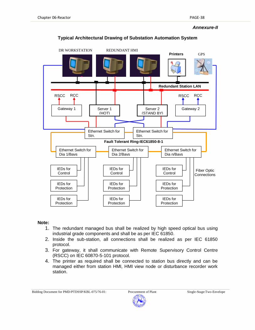
Chapter 06-Reactor PAGE-38
Bidding Document for PMD/PTDSSP/KBL-075/76-01: Procurement of Plant Single-Stage:Two-Envelope
Annexure-II
Typical Architectural Drawing of Substation Automation System
Note:
1. The redundant managed bus shall be realized by high speed optical bus using industrial grade components and shall be as per IEC 61850.
2. Inside the sub-station, all connections shall be realized as per IEC 61850 protocol.
3. For gateway, it shall communicate with Remote Supervisory Control Centre (RSCC) on IEC 60870-5-101 protocol.
4. The printer as required shall be connected to station bus directly and can be managed either from station HMI, HMI view node or disturbance recorder work station.
IEDs for Control
Ethernet Switch for Dia 1/Bays
IEDs for Protection
IEDs for Protection
IEDs for Control
Ethernet Switch for Dia 2/Bays
IEDs for Protection
IEDs for Protection
IEDs for Control
Ethernet Switch for Dia n/Bays
IEDs for Protection
IEDs for Protection
Ethernet Switch for Stn.
Ethernet Switch for Stn.
Server 1 (HOT)
Server 2 (STAND BY)
Gateway 2
RCC RSCC
Gateway 1
RCC RSCC
Printers
Redundant Station LAN
Fault Tolerant Ring-IEC61850-8-1
Fiber Optic Connections
DR WORKSTATION REDUNDANT HMI GPS

Chapter 06-Reactor PAGE-39
Bidding Document for PMD/PTDSSP/KBL-075/76-01: Procurement of Plant Single-Stage:Two-Envelope
5. The above layout is typical. However if any contractor offers slightly modified architecture based on their standard practice without compromising the working, the same shall be subject to approval during detailed engineering.

Chapter 19 – Fibre Optic Based Communication Equipments PAGE-1
Bidding Document for PMD/PTDSSP/KBL-075/76-01: Procurement of Plant Single-Stage:Two-Envelope
CHAPTER 19 Technical Specification for Fibre Optic Based Communication Equipments
Section 1
Introduction, General Information and General Requirement
For 400kV New Khimti–Barhabise, Barhabise-Lapsiphedi D/C Lines (Currently to be charged at 220 kV Voltage level) were interface with SDH/MUX telecommunication terminal equipment located in the Control Room required for the communication for the each 220 kV Lines with present SAS and SCADA system of the LDC. The same communication scheme shall be used for the 400 kV lines under the present scope of the contract. In the present scope of contract, the necessary interfacing of the existing communication system for the integration of 400 kV Lines at respective substations for onward transmission of Data and Voice communication upto LDC Khatmandu is included in the contract. Bidders are requested to read the entire chapter in conjuction with the chapter 1-project Specific Requirement (PSR) and quote their offer in the respective schedule of rates and prices. This document describes the technical specifications for Communication Equipment which includes Fibre Optic Terminal Equipment and Multiplexer Equipments for Establishment of Fibre Optic Communication System under the contract. This specification describes the functional and performance requirements of the system.
1.1 Scope and General Requirements
The broad scope of the procurement of this part include the survey, planning, design, engineering, supply, transportation, insurance, delivery at site, unloading, handling, storage, installation, termination, testing, training, and demonstration for acceptance, commissioning and documentation for:
(i) SDH Equipment along with suitable optical line interfaces & tributary cards.
(ii) Associated Termination equipment (Drop-insert multiplexers, subscriber line interfacing card etc.)
(iii) Local Craft Terminal (iv) All cabling, wiring, Digital Distribution Frame patch facilities, equipment
MDF's and interconnections to the supplied equipment at the defined interfaces.
(v) MDF & DDF cross connects required to route and activate circuits. (vi) System integration of the supplied subsystems and also integration with
existing communication equipment such as SDH, MUX etc. (vii) System integration of the supplied equipments (termination equipment
system) with existing equipments for seamless transmission of communication channel
(viii) Integration of supplied system with the User equipments such as RTUs, SCADA system, DPC equipment, PABX etc.
(ix) Maintenance of the supplied system

Chapter 19 – Fibre Optic Based Communication Equipments PAGE-2
Bidding Document for PMD/PTDSSP/KBL-075/76-01: Procurement of Plant Single-Stage:Two-Envelope
All other associated works/items described in the technical specifications for a viable and fully functional communication network.
1.2 General Requirements
The Contractor is encouraged to offer standard products and designs. However, the Contractor must conform to the requirements and provide any special equipment necessary to meet the requirements stated herein. It should be noted that preliminary design information and bill of quantity (BoQ) specified in this specifications are indicative only. The Contractor shall verify the design data during the site surveys & detail engineering and finalise the BoQ as required for ultimate design & system performance. The Bidder's proposal shall address all functional and performance requirements within this specification and shall include sufficient information and supporting documentation in order to determine compliance with this specification without further necessity for inquiries. An analysis of the functional and performance requirements of this specification and/or site surveys, design, and engineering may lead the Contractor to conclude that additional items are required that are not specifically mentioned in this specification. The Contractor shall be responsible for providing at no added cost to the Employer, all such additional items and services such that a viable and fully functional communication equipment system is implemented that meets or exceeds the capacity, and performance requirements specified. Such materials and services shall be considered to be within the scope of the contract. To the extent possible, the Bidders shall identify and include all such additional items and services in their proposal. All equipment provided shall be designed to interface with existing equipment and shall be capable of supporting all present requirements and spare capacity requirement identified in this specification. The communication equipment shall be designed and provisioned for expansions and reconfigurations without impairing normal operation, including adding and removing circuits. The offered items shall be designed to operate in varying environments. Adequate measures shall be taken to provide protection against rodents, contaminants, pollutants, water & moisture, lightning & short circuit, vibration and electro-magnetic interference etc. The Bidders are advised to visit sites (at their own expense), prior to the submission of a proposal, and make surveys and assessments as deemed necessary for proposal submission. The successful bidder (Contractor) is required to visit all sites. The site visits after contract award shall include all necessary surveys to allow the contractor to perform the design and implementation functions. The Contractor shall inform their site survey schedule to the Employer well in advance. The site survey schedule shall be finalised in consultation with the Employer. The Employer may be associated with the Contractor during their site survey activities. After the site survey, the Contractor shall submit to the Employer a survey report on each link and site. This report shall include at least the following items: (a) Proposed layout of Equipment in the existing rooms and buildings. (b) Proposed routing of power, earthing, signal cables and patch cords etc. (c) Confirmation of adequacy of Space and AC/DC Power supply requirements

Chapter 19 – Fibre Optic Based Communication Equipments PAGE-3
Bidding Document for PMD/PTDSSP/KBL-075/76-01: Procurement of Plant Single-Stage:Two-Envelope
(d) Proposals for new rooms/buildings if required (e) Identification of facility modifications if required (f) Identify all additional items required for integration for each site/location. 1.2.1 Synchronization of the Communication Network
The Contractor shall be responsible for synchronization of new communication equipment with existing network utilizing the existing clock (if available). The Contractor shall make an assessment of additional clock requirement for synchronization of the communication equipment.
1.3 General Responsibilities and Obligations This section describes the general responsibilities and obligations of the Contractor and the Employer. 1.3.1 Responsibilities for the Implementation Plan
The Bidder's technical proposal shall include a project implementation plan and schedule that is consistent with the implementation plan detailed in this specification. The implementation plan shall be modelled such that it provides fibre optic cabling system support for the activation of this Project. The Implementation plan shall include the activities of both the Contractor and the Employer, showing all key milestones and clearly identifying the nature of all information and project support expected from the Employer. The Employer and Contractor shall finalise the detailed Implementation plan following award of the contract. 1.3.2 Contractor's Responsibilities and Obligations
The Contractor shall be responsible for all cables and wiring associated with the equipment provided, both inside and outside buildings in accordance with technical specifications. The Contractor shall also be responsible for determining the adequacy of the local power source for the equipment and for wiring to it, with adequate circuit protective breakers. In addition, the Contractor shall be responsible for shielding equipment and cabling to eliminate potential interference to or from the equipment, and for earthing all cabinets and shields. Contractor's obligations include, but are not limited to, the following:
(1) Site visits, and surveys, necessary to identify and provide all equipment needed to implementation the network.
(2) Equipment Engineering and design specific to each location including review of, and conformance with local environmental and earthing considerations.
(3) Overall integration of communication equipments/subsystem procured in present and existing network.
(4) All cabling, wiring including supply, laying and termination etc of the cables, and distribution frame at wideband nodes required for full interconnectivity and proper operation of the telecommunications network including equipment supplied under this package and the connectivity and interfacing of user equipment.
(5) Installation and integration of network management software, hardware and firmware (as applicable).

Chapter 19 – Fibre Optic Based Communication Equipments PAGE-4
Bidding Document for PMD/PTDSSP/KBL-075/76-01: Procurement of Plant Single-Stage:Two-Envelope
(6) Project management, project scheduling, including periodic project reports
documenting progress, review meeting during the contract period. (7) Engineering and technical assistance during the contract and warranty period.
(8) Implement all minor civil works and identify any major civil works i.e. expansion
or construction of rooms, trenches necessary for installation of proposed equipment and provide the details of such work to the Employer.
(9) Factory and site testing of all hardware, software, and firmware provided. (10) Provide documented evidence of satisfactory Type Test performance to the
Employer and if required by The Employer, conduct type test. (11) Provide a Quality Assurance Plan, ensuring the Employer access to the
manufacturing process. (12) Training of the Employer personnel.
(13) Hardware, software, and firmware maintenance, debugging, and support of
the equipment through final acceptance, and maintenance on all new equipment through out the warranty period and for a period of six (6) years after warranty period.
(14) Availability of service, spare and expansion parts for the supplied items for the designed life of the equipment or seven (7) years after the declaration of withdrawal of equipment from production, whichever is earlier. However, the termination of production shall not occur prior to Operational Acceptance of the system by the Employer.
Detailed descriptions of the Contractor's obligations, in relation to individual items and services offered, are delineated in other sections of this specification. 1.3.3 The Employer Responsibilities and Obligations
The Employer will provide the following items and services as part of this Project:
(1) Overall project management of the project (2) Review and approval of the Contractor's designs, drawings, and
recommendations. (3) Communication network configuration data, including:
(a) Channel assignments for voice and data (b) Interconnection drawings for existing equipment
(4) Review and approval of test procedures. (5) Participation in and approval of "Type", factory and site acceptance tests
where testing is required. (6) Review and approval of training plans. (7) Providing support and access to facilities at the sites. (8) Implement the major civil works such as expansions or construction of rooms,
trenches etc. as required for the equipment to be provided by the Contractor. (9) Coordination of the Contractor's activities with the Employer's and constituents'
concerned departments. (10) Provide to the extent possible drawings for existing sites and facilities for which
equipment installations are planned. (11) Approval of the key personnel for the project
1.4 Applicable Standards

Chapter 19 – Fibre Optic Based Communication Equipments PAGE-5
Bidding Document for PMD/PTDSSP/KBL-075/76-01: Procurement of Plant Single-Stage:Two-Envelope
The following standards and codes shall be generally applicable to the equipment and works supplied under this Contract:
(i) IEEE 802.3 (ii) ITU-T/CCITT Recommendations, G.652, G.701, G.702, G.703, G.711/
12/ 14/ 35/ 36, G.721, G.742, G.811 and G.823 (iii) ITU-T/CCITT Recommendations, G.801, G.821, G.822, G.823, G.826. (iv) ITU-T/CCITT Recommendations of the V Series (v) ITU-T/CCITT Recommendations R35, R37, and R38A (or R38B) (vi) ITU-T/CCITT Recommendations M3010, G771 (vii) Internet Activities Board, RFC-1157 (SNMP) (viii) International Electrotechnical Commission standards, IEC 801-2/3/4/5,
IEC-255-4, IEC-255-5, IEC-870-2-1, IEC-721-3-3, IEC-529. (ix) International Electrotechnical Commission standards, IEC 1000-4-xx
series. (x) IEC publication 68, 68-2-2, 68-2-3, 68-2-14, 68-2-27, 68-2-32. (xi) ITU-T/CCITT Recommendations K.11, K.17, K.20. (xii) International CISPR standards
Specifications and codes shall be the latest version, inclusive of revisions, which are in force at the date of the contract award. Where new specifications, codes, and revisions are issued during the period of the contract, the Contractor shall attempt to comply with such, provided that no additional expenses are charged to the Employer without Employer's written consent. In the event the Contractor offers to supply material and/or equipment in compliance to any standard other than Standards listed herein, the Contractor shall include with their proposal, full salient characteristics of the new standard for comparison. In case values indicated for certain parameters in the specifications are more stringent than those specified by the standards, the specification shall override the standards. -------------------------------------------------- End of this Section --------------------------------
Section 2
Network Configuration and Equipment Characteristics 2.1 Introduction
This section describes the Fibre Optic Communication network configuration and the equipment characteristics for communication system to be installed under the project. The sub-systems addressed within this section are:
(1) Fibre Optic Transmission System (FOTS) (2) Termination Equipment Subsystems (3) MDF, DDF and Cabling
The requirements described herein are applicable to and in support of network requirements. The equipment supplied shall support existing network for Power system operational requirements.

Chapter 19 – Fibre Optic Based Communication Equipments PAGE-6
Bidding Document for PMD/PTDSSP/KBL-075/76-01: Procurement of Plant Single-Stage:Two-Envelope
The security related requirements of the equipment shall be as per relevant agency and shall be followed/complied by the vendor. The manufacturer shall allow the Employer and/or its designated agencies to inspect the hardware, software, design, development, manufacturing, facility and supply chain and subject all software to a security/threat check any time during the supplies of equipment.
The contractor shall ensure that the supplied equipments have been got tested as per relevant contemporary International Security Standards e.g. IT and IT related elements against ISO/IEC 15408 standards, for Information Security Management System against ISO 27000 series Standards, Telecom and Telecom related elements against 3GPP security standards, 3GPP2 security standards etc. from any international agency/ labs of the standards e.g. Common Criteria Labs in case of ISO/IEC 15408 standards until 31st March 2013. From 1st April, 2013, the certification shall be got done from authorized and certified agency. The Contractor shall also ensure that the equipment supplied has all the contemporary security related features and features related to communication security as prescribed under relevant security standards. A list of features, equipments, software etc. supplied and implemented in the project shall be given for use by the Employer In case of any deliberate attempt for a security breach at the time of procurement or at a later stage after deployment/installation of the equipment or during maintenance, liability and criminal proceedings can be initiated against the Contractor as per guidelines of Government department.
2.2 General Network Characteristics
2.2.1 Description
The fibre optic network shall be based on the Synchronous Digital Hierarchy (SDH) having bit rate of STM-1 (upgradable to STM-4) as indentified previously. The network shall consist of overhead fibre optic links with a minimum bit rate of Synchronous Transport Module-1 (STM-1). The Contractor can propose a system based on higher bit rate systems, if required, so as to meet the link budget requirements or any other specification requirement.
2.2.2 Functional Requirement The primary function of the communication network is to provide a highly reliable
voice and data communication system for grid operation in support of the SCADA/EMS/RTUs/PMUs. The communications support requirement for SCADA/EMS/RTUs/PMUs system is for low & high speed data, express voice circuits and administrative voice circuits as defined in appendices. A brief summary of the communication system requirements is as follows:
(a) High speed E1 channel support (b) 64kbps & nx64kbps data channel support

Chapter 19 – Fibre Optic Based Communication Equipments PAGE-7
Bidding Document for PMD/PTDSSP/KBL-075/76-01: Procurement of Plant Single-Stage:Two-Envelope
(c) Low speed (300 -1200 bps) data channel support (d) Voice (2 wires, 4 wires) channel support. (e) Data transport supporting Network Management channels (f) The connectivity envisaged between RTUs and Control Centre over TCP-IP
using Ethernet interface or over serial interface. 2.2.3 General Systems Requirements
Required characteristics are defined and specified herein at the system level, subsystem level, and equipment level.
2.2.3.1 System Synchronization
The Contractor shall synchronize the existing equipments and all the new equipments under the contract using existing Master clock, if available. The Contractor shall provide the additional clocks as required under the set of clock indicated in BoQ. In addition to GPS input reference, the synchronization clock must have provision to take INPUT reference coming from other clock. The contractor shall submit the synchronisation plan as per standard ITU-T G.811. All sync equipments proposed under this contract should meet ITU-T G.811 criterion. The holdover quality of slave clock, if any, shall meet ITU-T G.812 standard requirements. The Contractor shall provide system wide synchronization fully distributed throughout the telecom network and connected to all equipments new & existing. The Contractor shall submit the synchronization plan for the entire network meeting the requirement of ITU-T G.803. The synchronization plan shall clearly indicate the requirement of additional clocks with full justification. The system equipment requiring “clock” shall be connected to the master clock using external clocking. For this purpose, appropriate interfaces(s) in the transmission & termination equipment being supplied and all other associated hardware shall be provided by the Contractor.
2.2.3.2 System Maintainability
To facilitate performance trending, efficient diagnosis and corrective resolution, the system shall permit in-service diagnostic testing to be executed both locally and from remote locations, manually and/or initiated under TMN control (if provided). Such testing shall not affect the functional operation of the system.
2.2.3.3 System Upgradeability and Expandability
Equipment supplied shall be sized (though not necessarily equipped) to support system/ subsystem expansion to full capacity as provided by specified aggregate transmission rates. Equipment units provisioned for equipped subunits shall be terminated at appropriate patching facilities or termination blocks. Power supplies shall be sized for maximum equipped system capacity.

Chapter 19 – Fibre Optic Based Communication Equipments PAGE-8
Bidding Document for PMD/PTDSSP/KBL-075/76-01: Procurement of Plant Single-Stage:Two-Envelope
2.2.3.4 Equipment Availability The calculated availability of each fibre optic link (E1 to E1) shall be at least 99.999%. The calculated availability is defined as the theoretical availability determined by a statistical calculation based on the mean-time-between-failure (MTBF) and the mean-time-to-repair (MTTR) of the components and subsystems comprising the FOTS. For this analysis, an MTTR of atleast 4 hours shall be assumed. The down time of the fibre optic cable shall not be considered in the aforesaid availability calculations. The calculated failure rates of the units and the calculated availabilities of the equipment being offered shall be provided by the Contractor during detailed engineering.
2.2.3.5 Revision Levels and Modifications
All hardware, firmware and software delivered as part of the communications network shall be field proven and at the most of current revision level. All modifications and changes necessary to meet this requirement shall be completed prior to the start of the factory tests or under special circumstances, on written approval by Employer, prior to the completion of SAT.
2.2.3.6 Equipment Capacities
Equipment supplied shall be sized and equipped with sufficient capacity to support BoQ and configuration requirements as identified in the appendices. Each subsystem supplied shall be sized (to be equipped as specified) to support full subsystem expansion.
2.2.3.7 Redundancy Requirements and Protection Schemes
Equipment redundancy and Automatic Protection Schemes (APS) are specified in the Table 2-1. The failure of one element shall not prevent the use of any other that has not failed.
Table 2-1 Equipment Redundancy Requirements Summary
Fiber Optic transmission Equipment : SDH equipment Power Supply & Converters ------------------------------ Common Control* Cards ----------------------------------- MUX, DROP/INSERT Power Supply --------------------------------------------------- * = Common control cards which are essentially required for operation of the equipment.
1:1 APS or distributed power supply 1:1 APS 1:1 APS or distributed power supply

Chapter 19 – Fibre Optic Based Communication Equipments PAGE-9
Bidding Document for PMD/PTDSSP/KBL-075/76-01: Procurement of Plant Single-Stage:Two-Envelope
The offered equipment shall support at least SNCP as per standard ITU-T G.841. In
case the equipment offered by the Bidder does not support the above mentioned minimum protection methods, the bidder shall have to provide all additional equipment needed to provide same level of flexibility, redundancy and functionality at no additional cost to Employer. The bidders shall provide details of protection schemes supported in the Bid document. The offered equipment shall support automatic switchover function between the redundant modules and all required modules and hardware to support the automatic switch over shall be provided by the Contractor.
2.2.3.8 Lost Signal Recovery
At any digital signal level, reapplication of a lost signal shall result in automatic resynchronization and full restoration to normal operation without manual intervention. All alarms incident to the signal failure, shall be automatically cleared at the equipment, rack and monitoring levels and normal operation indications restored and reported if applicable.
2.2.3.9 Software Upgrades
The Contractor shall provide antivirus software along with all the computer hardware/software which shall be upgraded periodically till the maintenance services contract in the bid. Further, to meet all the specifications requirements during implementation and maintenance, if upgrade in the hardware/software of supplied item is required, the same shall be done by the contractor without any additional cost to the Employer.
2.2.3.10 General Site Considerations
All fiber optic links up to 175 kms transmission line length shall be implemented by the Contractor without repeaters. In order to meet the link budget requirement, the Contractor shall provide all the necessary equipments only in the end stations. The contractor may provide the optical amplifier, wave length translator, optical cards or high capacity SDH equipment with suitable rack/subrack to meet the maximum distance limit. All the provided equipments shall be monitored/managed by Craft Terminal.
2.2.3.11 Proposed Optical Fibre Characteristics
The link budget calculations and equipment design shall be based on the specified fibre parameters. The optical cables shall have Dual Window Single Mode (DWSM) fibres conforming to ITU-T Recommendations G.652D and the major parameters of these optical fibre(s) are defined in Table-2-2:
Table-2-2 Optical Fibre Characteristics
Fibre Description: Dual-Window Single-Mode (DWSM)

Chapter 19 – Fibre Optic Based Communication Equipments PAGE-10
Bidding Document for PMD/PTDSSP/KBL-075/76-01: Procurement of Plant Single-Stage:Two-Envelope
Table-2-2 Optical Fibre Characteristics
Mode Field Diameter: 8.6 to 9.5 μm (±0.6 µm)
Cladding Diameter: 125.0 μm + 1μm
Mode field Concentricity Error: < 0.6μm
Core-Clad concentricity error: < 1.0μm
Cladding non-circularity < 1%
Cable Cut off Wavelength: < 1260 nm
1550 loss performance As per G.652D
Proof Test Level 0.69 Gpa
Attenuation coefficient @1310nm < 0.35 dB/Km @1550nm < 0.21 dB/Km
Attenuation variation with wavelength
1285 nm - 1330 nm
1525 nm – 1575 nm
Attenuation coefficient @1310 ± 0.05 dB
Attenuation coefficient @1550 ± 0.05 dB Point discontinuities
< 0.1dB
Chromatic Dispersion; Max.: Zero Dispersion Wavelength: Zero Dispersion Slope:
18.0 ps/(nm x km) @ 1550 nm 3.5 ps/(nm x km) @ 1288-1339nm 5.3 ps/(nm x km) @ 1271-1360nm 1300 to 1324nm 0.092 ps/(nm2xkm) maximum
Polarization mode dispersion coefficient
< 0.2 ps/km^1/2
Temperature Dependence:
Induced attenuation < 0.05 dB (-60 deg C - +85 deg C)
Bend performance: @1310nm (75+2 mm dia Mandrel), 100 turns;
Attenuation rise 0.05 dB
@1550nm (30+1 mm dia Mandrel), 100 turns;
Attenuation rise 0.10 dB
@1550nm (32+0.5 mm dia Mandrel), 1 turn;
Attenuation rise 0.50 dB
2.2.5 Fibre Optic Link Lengths
The fiber optic route lengths are as specified in appendices. The lengths specified in
appendices are the transmission line route lengths; however the actual fiber cable length shall exceed the route lengths on account of extra cable requirement due to sag, jointing & splicing, approach cabling etc. For bidding purposes the Contractor

Chapter 19 – Fibre Optic Based Communication Equipments PAGE-11
Bidding Document for PMD/PTDSSP/KBL-075/76-01: Procurement of Plant Single-Stage:Two-Envelope
may assume an additional cable length of 5% of given route length + 1Km towards approach cable for calculating the link length. The exact cable lengths shall be determined by the Contractor during the survey. The same shall be used by the Contractor for final link design during the detailed engineering of the project.
2.3 Fibre Optic Transmission System
The Fibre Optic Transmission System (FOTS) is defined herein to include ETSI digital optical line termination equipment. The FOTS shall be based on SDH technology. Minimum aggregate bit rate shall be STM-1 (upgradable to STM-4) and equipped with 2 nos. of minimum 16 port E1 interface(G.703) card, one no. of minimum 4 port Ethernet interface (IEEE 802.3/IEEE 802.3u) card supporting layer 2 switching as tributaries. The Ethernet interfaces shall support VLAN (IEEE 802.1P/Q), spanning tree (IEEE 802.1D) quality of service. Protection scheme for Ethernet traffic should be ERPS based (Ethernet ring protection scheme) as per ITU-T G.8032. The Contractor shall provide (supply and install) connectorised jumpers (patch cords) for FODP-to-equipment and equipment-to-equipment connection. Two number spare jumpers shall be provided for each equipment connection. Fiber jumpers shall be of sufficient lengths as to provide at least 0.5m of service loop when connected for their intended purpose.
2.3.1 SDH Equipment
2.3.1.1 Functional Requirement
There is a requirement for different types of equipment under this project which are described in this section. For the purpose of BOQ, the SDH Equipment is considered to be divided in three parts i.e. Optical interface/SFP, Tributary Cards (Electrical tributaries such as E1 & Ethernet 10/100 Mbps) and Base Equipment (Consisting of Common Cards, Control Cards, Optical base card, Power supply cards, sub-rack, cabinet, other hardware and accessories required for installation of equipment i.e. everything besides optical interface/SFP and tributary cards).
If bidder is offering equipment with multifunction cards such as cross-connect or control card with optical interface/SFP or tributary interface, such type of multifunction card shall be considered as Common control card and shall be the part of base equipment. In case optical interface/SFP is embedded with control card, the adequate number of optical interface/SFPs shall be offered to meet the redundancy requirements of the specifications. Further, control card shall not be equipped with more than one optical interface/SFP and optical base card shall not be equipped with more than two optical interface/SFPs.
The equipment shall be configurable either as Terminal Multiplexer (TM) as well as ADM with software settings only.
SDH ADM
The aggregate interfaces shall be (at least) STM-1 towards at least two protected directions (Protected as specified in this specifications). At present the equipment shall be equipped with a 2 nos., min.16 E-1 port electrical tributary cards & one no.,

Chapter 19 – Fibre Optic Based Communication Equipments PAGE-12
Bidding Document for PMD/PTDSSP/KBL-075/76-01: Procurement of Plant Single-Stage:Two-Envelope
min.4 port Ethernet interface card as tributaries. The equipment shall provide access to full STM-4 payload.
The offered STM-1 SDH equipment shall be upgradeable to STM-4 by changing optical line cards only. Cross connection (VC4) capability of offered SDH equipment shall be provided according to STM-4 equipment. The contractor shall demonstrate the STM-4 upgradeability during FAT.
2.3.1.2 Redundancy and Protection
Two fibre rings shall be implemented wherever the network permits. On linear sections of the network, protected links using 4 fibres shall be implemented.
2.3.1.3 Service Channel
Service channels shall be provided as a function of the SDH equipment and shall be equipped with Service Channel Muldems that shall provide at a minimum: One voice channel (order wire) with analog interface (0.3 to 3.4 kHz) and one data channel. Both omnibus and selective calling facilities shall be provided. There shall be a facility to extend the line system order-wire to any other system or exchange lines on 2W/4W basis.
2.3.1.4 Supervision and Alarms
ISM (In Service Monitoring) circuitry shall be provided as a function of the SDH equipment. Local visual alarm indicators shall be provided on the equipment, as a rack summary alarm panel. Alarms shall be as per ITU-T Standards G.774, G.783 and G.784. Additionally, F2/Q2 interfaces for a local craftsperson terminal interface and remote equipment monitoring is required.
The Equipment shall support collection of at least four (4) external alarms for monitoring and control of station associated devices by the TMN.
2.3.1.5 Synchronisation
The equipment shall provide synchronisation as per Table 2-2. One 2MHz synchronisation output from each equipment shall be provided.
2.3.1.6 Electrical and Optical I/O Characteristics and General Parameters Table 2-3 provides the electrical and optical characteristics as well as other general parameters for SDH equipment.
Table 2-3
Electrical and Optical I/O Characteristics and General Parameters Optical Wavelength NOTE (1)
1310/1550nm
Optical Source NOTE (2)
Laser
Optical Source Lifespan
Better than 5 X10⁵ hours
Optical Fibre Type
G.652 D

Chapter 19 – Fibre Optic Based Communication Equipments PAGE-13
Bidding Document for PMD/PTDSSP/KBL-075/76-01: Procurement of Plant Single-Stage:Two-Envelope
Optical Connectors Type FC-PC Transmission Quality
Per ITU-T G.821, G.823, G.826
Source Primary Power
-48 Vdc
Equipment Specifications
Per ITU-T G.783
Tributary, Electrical Interface
Per ITU-T G.703, 75 Ω
Ethernet Interface 10/100 Mbps SDH Bit Rates
Per ITU-T G.703
Optical Interfaces
Per ITU-T G.957, G.958
Frame and Multiplexing Structure for SDH
Per ITU-T G.707
Synchronization
Per ITU-T G.813
Management Functions
Per ITU-T G.774, G.784
Protection Architectures
Per ITU-T G.841
Built In Testing and Alarms
Per ITU-T G.774, G.783, G.784
NOTE (1) Optical wavelength shall be selected considering the characteristics
of the optical fibre and the link budget.
NOTE (2) Eye Safety for Laser Equipment: To avoid eye damage, when a
receiver detects a line interruption, it is required that the optical power of the laser shall be reduced to safe limits on the transmitter in the opposite direction as per ITU-T G.958.
NOTE (3) In case other than FC-PC connector is provided in the equipment,
suitable patch cord with matching connector are to be provided to connect with FODP.
2.3.2 Optical Link Performance Requirements
The optical fibre link performance requirements are specified as follows:
2.3.2.1 Link Budget Calculations
The fibre optic link budget calculations shall be calculated based upon the following criteria:
(1) Fibre attenuation: The fibre attenuation shall be taken to be the guaranteed maximum fibre attenuation i.e. 0.21 dB/Km @1550nm and 0.35 dB/km @1310nm.
(2) Splice loss: Minimum 0.05 dB per splice. One splice shall be considered for every 3 kms.
(3) Connector losses: Losses due to connectors shall be considered to be minimum 1.0 dB per link.
(4) Equipment Parameters: The equipment parameters to be considered for link budget calculations shall be the guaranteed “End of Life (EOL)” parameters. In case, the End of Life parameters are not specified for the SDH equipment, an

Chapter 19 – Fibre Optic Based Communication Equipments PAGE-14
Bidding Document for PMD/PTDSSP/KBL-075/76-01: Procurement of Plant Single-Stage:Two-Envelope
End of Life Margin of at least 2 dB shall be considered and a similar margin shall be considered for optical amplifiers.
(5) Optical path Penalty: An optical path penalty of at least 1 dB shall be considered to account for total degradations due to reflections, inter symbol interference, mode partition noise and laser chirp.
(6) Maintenance Margin: A maintenance margin of at least 2.5 dB/100Km shall be kept towards cabling, repair splicing, cable ageing and temperature variations etc.
(7) Other losses: Other losses, if any required specifically for system to be supplied shall also be suitably considered.
(8) Dispersion: The fibre dispersion shall be taken to be the guaranteed maximum dispersion i.e. 18 ps/nm.Km @1550 nm & 3.5 ps/nm.km @ 1310 nm for DWSM fibres.
(9) Bit Error Rate: The link budget calculations shall be done for a BER of 10 -10.
The bidders shall determine the total link loss based on the above parameters and shall submit the system design (including link budget calculations) for each category of fibre optic link during detailed engineering.
For finalising the FOTS system design & BOQ, above methodology shall be adopted taking into account fibre attenuation, dispersion and splice loss determined during the detailed engineering. Accordingly, additions and deletions from the contract shall be carried out based on unit rates indicated in the contract.
2.3.2.2 Link Performance
The Link performance for ES, SES and BER for the fibre optic links shall correspond to National Network as defined in ITU-T G.826.
2.3.2.3 FODP to SDH Equipment
The Contractor shall be responsible for connectivity between the FODP and the SDH equipment. The Contractor shall provide FC PC coupled patch cords. The patch-cord length between the FODP & equipment rack shall be suitably protected from rodents, abrasion, crush or mechanical damage.
2.4 Termination Equipment Subsystem
The Termination Equipment Subsystem is defined to include the equipment that interfaces (adapts) the subscriber (user) to the Fibre Optic Transmission System (FOTS). A Functional description of these equipments are as follows:
2.4.1 Functional Description

Chapter 19 – Fibre Optic Based Communication Equipments PAGE-15
Bidding Document for PMD/PTDSSP/KBL-075/76-01: Procurement of Plant Single-Stage:Two-Envelope
The transmission network node provides subscriber interface to the transmission network and/or switching/routing. For clarity, the basic functions accomplished at the network nodal points, are described briefly as follows:
Primary Multiplexer shall be used to accomplish subscriber connectivity to the Digital Communication Network. Subscriber Line Units shall provide analog to digital and direct digital conversion to 64 Kbps digital channel. In the CEPT standard hierarchy, thirty (30) such 64 Kbps digital channels shall be Time Division Multiplexed (TDM) resulting in a single 2.048 Mbps (E-1) digital bit stream.
Digital Drop-Insert and Branching Equipment shall be used to digitally interface a small number of channels at spur locations without requiring successive D/A and A/D conversions of the throughput channels.
The equipment shall also have an interface for external 2048 kHz synchronisation signal according to ITU-T Recommendation G.703.
2.4.2 First Order (Primary) Multiplexing
The Contractor shall be required to provide E-1 Drop & Insert Multiplexer and E-1 Channel Bank primary multiplexing in compliance with the electrical input-output characteristics provided in Table 2-4.
2.4.2.1 Drop & Insert Primary Multiplexing
Drop & Insert primary multiplexing in conformance with CEPT E-1 characteristics shall be required at locations where the subscriber requirement is minimal. The drop and insertion of up to thirty 64 Kbps channels supporting subscriber line units (SLU) shall be required at intermediate locations. The Drop & Insert Muxes supplied shall be performance and card compatible with the Channel Bank Equipment provided so that all Subscriber Line Interface cards are interchangeable.
Table 2-4
CEPT E-1 Standard First Order Multiplexing
Electrical Input/Output Characteristics Applicable Standards:
CEPT per CCITT Recommendation G.702, G.703, G.711 and G.712
Number of Tributaries:
30 X 64 Kbps
Alternative Sub-rate Tributaries:
n X 64 Kbps V.36
64Kb/s V.11/V.36 Output Aggregate Rate:
Interface Code:
Impedance:
Peak Level @ 120 ohm:
Peak Level @ 75 ohm:
Maximum Insertion Loss:
2.048 Mb/s ± 50 ppm
HDB3
75 ohm unbalanced
3.0 volts ± 10%
2.37 volts ± 10%
6 dB

Chapter 19 – Fibre Optic Based Communication Equipments PAGE-16
Bidding Document for PMD/PTDSSP/KBL-075/76-01: Procurement of Plant Single-Stage:Two-Envelope
Signal Waveform:
Frame Structure:
Jitter Performance:
Per CCITT G.703
Per CCITT G.742
Per CCITT G.823 Power Supply Voltage:
-48 Vdc
2.4.2.2 Channel Banks (Mux, Drop/Insert)
User voice and data equipment interfacing requirements are defined at the subscriber line level. Primary multiplexing in conformance with CEPT E-1 characteristics shall be used to provide first order multiplexing of up to thirty 64 Kbps channels supporting Subscriber Line Units (SLUs).
2.4.2.3 Subscriber Line Units\Subscriber Line Interface Cards
The terms Subscriber Line Interface Cards and Subscriber Line Units have been used interchangeably throughout the specification. Multiple configurations of SLUs shall be required to provide subscriber to primary multiplexer Bank interfacing for a variety of voice and data communications. In case there are changes in number or type of cards because of changes in channel requirements, the contract price shall be adjusted accordingly.
The SLU interface requirements are discussed in the following subparagraphs:
(A) Voice Channels
The voice channel requirement is for (I) 4-Wire E&M trunking in support of PABX trunks & PLC VF and (II) 2-Wire telephonic interfaces. 2 wire SLUs shall be DTMF/TP optioned for 2-wire loop start or 2-wire GND start. The voice cards shall utilize ITU.T A - law companded PCM G.711, 64 kbits/s encoding. The voice card requirements are indicated in the BoQ in appendices.
(B) Sub-Channel Data Multiplexing
For this Project, the RTU data interface to the wideband telecommunications network node shall be defined at the DTE level at low-speed rates of 300, 600 and 1200 baud. The port shall be compatible with RS232C interface. The Contractor shall be required to furnish 64 Kbps SLU asynchronous dataplexing for at least 4 selectable low speed DTE interfaces whenever multiple asynchronous data circuits are required.
(C) Synchronous Data
The Contractor shall provide a direct DTE interface for synchronous communications at speed of 64Kbps and compatible with CCITT G.703 Kbit/s, V.35 and X.21 interfaces. Data rate selection shall be switch selectable or programmable.
(D) Nx64 kbps Synchronous Data

Chapter 19 – Fibre Optic Based Communication Equipments PAGE-17
Bidding Document for PMD/PTDSSP/KBL-075/76-01: Procurement of Plant Single-Stage:Two-Envelope
There is also a requirement for N x 64 kbps V.35, X.21 interfaces. The tentative quantities have been identified in the appendices. However the final BOQ shall be worked out during detailed design and contract price shall be adjusted accordingly.
2.5 MDF, DDF and Cabling
For the purposes of the specification, the contractor shall provide cabling, wiring, DDF patching facilities and MDFs interfacing to the wideband telecommunications system. Equipment and material components for MDF, DDF and cabling are also part of this procurement. It shall be the Contractor's responsibility to provide all cable support required for full supplied equipment interconnection with the MDF and shall be in accordance with communications industry standard practices and the requirements mentioned in the technical specifications.
2.5.1 Digital Distribution Frame Functional Requirements
The Contractor shall provide DDF for Digital Signal Cross connect (DSX) Broadband-quality (better than 20 MHz) patching facilities configured "normally-thru" with Equipment, Line and Monitor Patch Jacks. DDFs shall provide the following basic functions:
(i) "Normally thru" circuit routing
(ii) Circuit rerouting via patch cord assemblies
(iii) Circuit disconnect and termination
All DDFs shall be sized and equipped to support the offered configuration of the provided equipment. Independent Transmit and Receive patch jack assemblies (line and equipment) shall provide for separate transmit and receive single-plug patching. Transmit and receive patch jack assemblies shall be located side-by-side such that dual-plug patch cord assemblies may be used to route both transmit and receive for the same circuit.
2.5.2 Main Distribution Frames
The Contractor shall make provision for cross connection of subscriber services to the subscribers utilizing Krone type or equivalent and shall provide full connectivity up to and terminated on the equipment side of the appropriate DDFs and line side of MDFs. The Contractor shall terminate on the equipment side of patching facilities provided by other contracts and shall provide DSX type patching facilities supporting aggregate bit streams (i.e. dataplexers and E-1 Channel Banks). Separate Patch panels or MDFs shall be provided for Data and Voice. All cross connects shall be accomplished utilizing one, two or three pair patch cords. Patch plugs are permissible for direct one-to-one circuit "cut-thru".
2.6 Patch Cords
The Contractor has to supply FC PC coupled Patch cords as described in BOQ. The Patch cord return loss shall be equal to or better than 40 dB and insertion loss equal to or less than 0.5 dB. 2.6 Telecommunication Management Network / Network Management System
(As Applicable)

Chapter 19 – Fibre Optic Based Communication Equipments PAGE-18
Bidding Document for PMD/PTDSSP/KBL-075/76-01: Procurement of Plant Single-Stage:Two-Envelope
The Contractor shall provide a Telecommunications Management Network System (TMN) for operational support to the FOTS and associated Termination equipment subsystems. This TMN shall provide the capability to monitor, reconfigure, and control elements of the telecommunications network from a centralized location and at each node of the network where equipment is located. This TMN system shall assist Employer/Owner in the operations and maintenance of the wideband communication resources of the including detection of degraded circuits, system performance, the diagnosis of problems, the implementation of remedial actions and the allocation or reallocation of telecommunications resources and addition/deletion of network elements. The contractor shall supply preferably a single TMN for all the NEs (Network Elements) such as SDH equipment, Mux, Drop-Insert, DACS etc. In case a single TMN can not be provided for all the NEs, the contractor may supply separate TMNs. Each of the offered TMN shall meet the requirements indicated in this section. The bidder shall provide details of the offered TMN in the bid. 2.7.1 Applicable Standards
The TMN design concept, functional and informational architecture and physical architecture, shall be in compliance with ITU-T Recommendation M.3010. The offered TMN system shall be capable of integration to other supplier’s Network Management System (NMS) upwardly through North bound interfaces. The north bound interface in the EMS shall be CORBA/TMF-814 compliant. 2.7.2 TMN Architecture The TMN shall provide a. Collection of Management data from all Network Elements (NEs) supplied under this
package. The minimum monitoring and control requirements for the communication equipment shall be as defined in this section.
b. Processing of above management data by using processor(s) located at control
Centre and additional intermediate station processor(s), wherever required. c. Monitoring and control of the NEs as defined below:
I) TMN system at LDC (including local operator console, if applicable) shall support management of all equipments supplied and monitoring of the entire regional network supplied under this package. At a minimum functions of Network management layer (NML) and Element management layer (EML) as defined in CCITT M3010. The detailed functions are listed in TS.
II) Monitoring and control of NEs using Craft Terminals as defined in this Section.
d. Supervisory monitoring and control of the following station associated devices:
I) Intrusion Detection Alarms II) Power Failure III) Fire and Smoke Detection IV) Environmental Control (Temperature, Humidity etc.)

Chapter 19 – Fibre Optic Based Communication Equipments PAGE-19
Bidding Document for PMD/PTDSSP/KBL-075/76-01: Procurement of Plant Single-Stage:Two-Envelope
e. Communication channel support for TMN System as specified in Technical Specifications (TS).
The supplied TMN system shall be capable of handling all management functions for at least 150% of the final network elements. Further, the centralised TMN system shall also have provision for addition of at least two remote operator consoles. The TMN hardware shall be so designed that failure of a single processor/component (router, switch, converter etc.) shall not inhibit any of the functionality of the TMN at control centre. The Contractor shall submit for Employer’s approval the TMN architecture describing in detail the following subsystems/features:
a. Database used in TMN
b. Master Processor, server/workstation, LAN, Peripherals and hardware
c. Software and operating system
d. Local Consoles/remote consoles
e. Craft Terminals
f. Data communication between NEs, Remote/Local Consoles and TMN
Processor(s)
g. Routers/Bridges
h. Expansion Capabilities
2.7.3 Management Functions
The TMN shall support following Management functions: 2.7.3.1 Configuration Management
Configuration management is concerned with management, display, and control of the network configuration. Minimum specific requirements that shall be satisfied include the following:
a. Provide tools to establish and maintain the backbone topology and configuration information and provide graphical maps depicting the configurations.
b. Gather descriptive information about the current configuration of the
equipment, provide operator displays, and prepare reports.
c. Provide tools for planning, establishing, and changing the static equipment configuration. Provide for changes to the equipment configuration in response to equipment failures, planned upgrades, and operator requests to take equipment offline for testing.
d. Provide verification testing to support new equipment installation.

Chapter 19 – Fibre Optic Based Communication Equipments PAGE-20
Bidding Document for PMD/PTDSSP/KBL-075/76-01: Procurement of Plant Single-Stage:Two-Envelope
2.7.3.2 Fault Management Fault management is concerned with detecting, diagnosing, bypassing, directing service restoration, and reporting on all the backbone network equipment, systems, and links. Minimum specific requirements that shall be satisfied include the following:
a. Display equipment status in a consistent fashion regardless of the source of the data on a graphical topological, map-type display. Status shall be displayed through the use of colours on links and nodes as well as through text.
b. Obtain status and detect faults through periodic polling, processing of
unsolicited alarms and error events, and periodic testing for connectivity.
c. Maintain an alarm summary of unacknowledged alarm events on the management station display and maintain a log of all received alarms. The operator shall be able to acknowledge and clear alarms individually and as a group. The use of alarm correlation techniques is encouraged to minimize the proliferation of alarms caused by a single, common event. All alarms shall be configurable as critical alarms, major alarms and minor alarms with different colours.
d. Provide the capability to diagnose and isolate failures through analysis of error
and event reports and through the use of both on-line and off-line diagnostic tests and display of monitored data.
e. The criteria for fail over shall be configurable as automatic fail over to redundant
equipment wherever possible and through operator-initiated actions where automatic fail over is not possible. The status of fail over shall be reported to the NMS.
f. Track network equipment failure history.
2.7.3.3 Performance Management
Performance management is concerned with evaluation of the use of network equipments and their capability to meet performance objectives. Minimum specific requirements that shall be satisfied include the following:
a. Provide support for an operator to initiate, collect, and terminate performance
metrics under both normal and degraded conditions. For example, BER of each link, together with other data measured at each node, shall be available on operator request (atleast for SDH).
b. Monitor point to point & end to end signal quality and history. Provide operator
controls to monitor performance of specified events, measures, and resources (atleast for SDH). Specifically provide displays to permit the operator to:
1. Select/deselect network equipments, events, and threshold parameters
to monitor
2. Set monitoring start time and duration or end time

Chapter 19 – Fibre Optic Based Communication Equipments PAGE-21
Bidding Document for PMD/PTDSSP/KBL-075/76-01: Procurement of Plant Single-Stage:Two-Envelope
3. Set monitoring sampling frequency
4. Set/change threshold values on selected performance parameters
5. Generate alarm events when thresholds are exceeded.
6. Set multiple thresholds on certain performance parameters. Alarm
categories include as a minimum a warning and a failure.
7. Calculate selected statistical data to measure performance on selected equipment based on both current and historical performance data maintained in performance logs. Performance data provided is limited to what is available from the equipment Contractors.
8. Provide graphical displays of point to point and end to end current
performance parameter values. Provide tabular displays of current, peak, and average values for performance parameters.
9. Generate reports on a daily, weekly, monthly, and yearly basis
containing system statistics.
2.7.3.4 Security Management
The TMN shall be provided with security features to limit access to monitoring and control capabilities to only authorized personnel. One access level of System Administrator and at least two levels of operator access shall be provided - read (view) only, and write (configure). The system administrator shall be able to create, define and modify operators with different access levels, network domains and perform all kind of maintenance and up gradation of the TMN system. With "read only" access level, network parameters should only be viewed. Access to database maintenance, command control and test functions shall be available with "write " access level. Means shall be provided to ensure only one authorized user has write capability for a selected domain of the network. It shall be possible to define multiple domains for purposes of monitoring and control. Human error and conflict detection are also required. Such errors and access violations shall be reported to the offending user as error messages and warnings. 2.8 Communication Channel Requirement and Integration
Communication requirements for TMN system have not been considered in Appendices and the Contractor shall provide these as a part of TMN system. The Contractor shall provide all required interface cards / devices, LAN, routers/bridges, channel routing, cabling, wiring etc. and interfacing required for full TMN data transport. The TMN data transport shall utilize the wideband communications transmission system service channel in the overhead whenever possible. This will provide inherent critical path protection
Should the configuration requirements dictate multiple TMN station processors, the TMN Master Station shall require bidirectional data transport with its station processor(s). This communications interfacing shall be via critically protected data channels. It shall be the

Chapter 19 – Fibre Optic Based Communication Equipments PAGE-22
Bidding Document for PMD/PTDSSP/KBL-075/76-01: Procurement of Plant Single-Stage:Two-Envelope
Contractor's responsibility to provide for and equip all necessary critically protected TMN data channel support. In case supervisory channels are not available, the Contractor shall provide suitable interfaces in their supplied equipment for transport of TMN data. The Contractor shall also be responsible for providing suitable channels with appropriate interfaces to transport the TMN data. The NMS information of existing PDH & SDH system shall be transported through the new communication network, wherever required, up to the NMS location. The NMS information of the new SDH & PDH system being procured under the package shall be transported through the existing communication network using 64 kbps/2Mpbs (G.703) interfaces. Any hardware required for above interfacing shall be provided by the Contractor. The bidders shall describe in the proposal the TMN data transport proposed to be used by the bidder in detail including capacity requirements and various components/equipment proposed to be used. 2.9 Craft Terminal
Each equipment (SDH equipment, Mux, Drop/Insert and DACS etc.) on the fibre optic communication network shall include provision for connecting a portable personal computer (PC) to be known as craft terminal to support local commissioning and maintenance activities. Through the use of this PC and local displays/controls, the operator shall be able to:
a. Change the configuration of the station & the connected NEs. b. Perform tests c. Get detailed fault information
The craft terminal shall be connected to the interface available in the communication equipment. Portable (laptop) computers (Craft terminals), each complete with necessary system and application software to support the functions listed above, shall be supplied to the employer as per BOQ given in the appendices.
2.10 Hardware Requirements
2.10.1 Master Processor, Server/Workstation and Craft Terminal
The server/workstation and craft terminal shall have suitable processor(s) which shall be
sufficient to meet all the functional requirement and expansion capabilities stipulated in
this specification. Only reputed make like Dell, IBM, HP, Compaq make shall be supplied.
The server shall have minimum configuration of 3GHz for CISC based or 1.6GHz for
RISC based processor, 2GB RAM, DVD-ROM drive, redundant 80 GB internal Hard Disk
Drive, 101-Enhanced style keyboards, mouse, parallel, serial, USB(2.0) ports and hot
swap redundant power supply. VDUs shall be 17" TFT active matrix color LCD with a
minimum resolution of 1024 X 768. Appropriate network drive card shall also be provided
wherever required. However, the internal hard disk drive for the server shall be redundant

Chapter 19 – Fibre Optic Based Communication Equipments PAGE-23
Bidding Document for PMD/PTDSSP/KBL-075/76-01: Procurement of Plant Single-Stage:Two-Envelope
and all the data shall be mirrored. Further, the TMN software shall support data mirroring
on redundant disk drives.
The workstation shall have minimum configuration of 2.4GHz for CISC or 1.4GHz for
RISC based processor, 1GB RAM, DVD-RW drive, 160 GB Hard Disk Drive, 101-
Enhanced style keyboards, mouse, parallel, serial and USB (2.0) ports. VDUs shall be 19"
TFT active matrix color LCD with a minimum resolution of 1024 X 768. Appropriate
network drive card shall also be provided wherever required.
CPU enclosures shall be desktop type and shall include available expansion slots except
for the Craft Terminal which shall be a laptop. The craft terminal shall have minimum
configuration of 2.4 GHz, 2 GB RAM, 256 MB VRAM, DVD RW drive, 160 GB Hard Disk
Drive, keyboard, mouse/trackball etc., parallel, serial/USB (2.0) ports to accommodate
printers, and Internal/external Data/Fax modem and a battery back-up of at least 60
minutes. VDUs shall be 15" TFT active matrix color LCD with a minimum resolution of
1024 X 768.
2.10.2 Peripherals and hardware
TMN system shall be provided with laser printer. The laser printer shall have a minimum print speed of 17 pages per minute and a minimum resolution of 1200 x 1200 dpi. The laser printer shall have parallel and LAN ports for connecting to TMN system.
The laser printer under this specification shall be black & white and include print enhanced buffering to prevent loss of print data in the event of a print failure.
2.10.3 Local/Remote Operator Consoles (As Applicable)
The Contractor shall provide operator consoles sized and equipped to support the subsystem(s) furnished and in compliance with the specification. The console shall provide hardware interfacing for the TMN users to the software operating support systems. At a minimum, a console shall include the hardware similar to a workstation.
2.10.4 Power Supplies
The TMN system shall use 220 volts 50 Hz A.C or -48 volt D.C as available at site for its operation as available at site. 2.11 General Software/Firmware Requirements
Due to various alternative design approaches, it is neither intended nor possible to specify all software and firmware characteristics. It is the intent herein to provide design boundaries and guidelines that help to ensure a demonstrated, integrated program package that is maintainable and meets both hardware systems requirements and the customer's operational requirements. 2.11.1 Operating System Software

Chapter 19 – Fibre Optic Based Communication Equipments PAGE-24
Bidding Document for PMD/PTDSSP/KBL-075/76-01: Procurement of Plant Single-Stage:Two-Envelope
Operating system software shall be provided to control the execution of system programs, application programs, management devices, to allocate system resources, and manage communications among the system processors. The contractor shall make no modifications to the OEM's operating system, except as provided as USER installation parameters. 2.11.2 Applications Software
All applications software shall be written in a high-level programming language unless developed using industry proven application programs and development tools provided with the system. The contractor shall make no modifications to the applications program except as provided as USER development tools.
2.11.3 Software Utilities
A utility shall be provided to convert all reports into standard PC application formats such as excel. 2.11.4 Revisions, Upgrades, Maintainability
All firmware and software delivered under this specification shall be the latest field proven version available at the time of contract approval. Installed demonstration for acceptance shall be required. All firmware provided shall support its fully equipped intended functional requirements without additional rewrite or programming. All software shall be easily user expandable to accommodate the anticipated system growth, as defined in this specification. Reassembly recompilation or revision upgrades of the software or components of the software, shall not be necessary to accommodate full system expansion. Software provided shall be compliant with national and international industry standards.
2.11.5 Database(s)
The contractor shall develop all the databases for final wideband network following the global acronyms for all stations. Database(s) to be provided shall contain all structure definitions and data for the integrated functional requirements of TMN system. TMN operator Groups shall share the same virtual database. This means that they shall share the same database and database manager, whether or not physically separate databases are maintained. 2.11.6 Help
All applications shall be supported by USER accessible HELP commands that shall assist the user in the performance of its tasks. HELP commands for an application shall be available to the user from within the active application and shall not interfere with the activities of the application. ---------------------------------------------------End of the Section---------------------------------
Section - 3
Environment, EMI, Power Supply, Cabling and Earthing

Chapter 19 – Fibre Optic Based Communication Equipments PAGE-25
Bidding Document for PMD/PTDSSP/KBL-075/76-01: Procurement of Plant Single-Stage:Two-Envelope
The purpose of this section is to describe the minimum general equipment characteristics and specifications for environmental conditions, source power conditioning and backup, equipment construction, and installation. The section also highlights the stringent Electro Magnetic Compatibility (EMC) guidelines for equipment that will be operated under the severest Electro Magnetic Interference (EMI) and Electro Static Discharge (ESD) conditions expected in an Extra High Voltage (EHV) power system environment. 3.1 Environmental Requirements Equipment and their components provided under this specification shall operate reliably under the following environmental conditions. 3.1.1 Temperature and Humidity
Most of the equipment will not be installed in environmentally controlled shelters. Therefore, equipment shall operate in accordance with the limits shown in Table 4-1.
Table 4-1 Environmental Operating Limits
Temperature Range: Specification Operation without damage Shipping/storage
(Un Controlled Environment)
0 to 45°C
-10 to 55°C
-40 to 60°C Relative Humidity, non-condensing
Upto 90%
Elevation: Operating Non-operating
to 3,000 m to 10,000 m
For each location, the Contractor is required to assess the environmental conditions for the equipment to be installed under this specification. The Contractor is responsible for all necessary enclosure, rack or equipment upgrades to ensure the proper operation of the installed equipment. 3.1.2 EMI and Electrostatic Interference
At each location, the Contractor shall assess the need for shielding against radiated emissions and shall provide recommended solutions for any EMI problem found at each location. Specifications provides the type of immunity tests for which the equipment shall be required to pass without failure. For the individual tests to be carried out at the different interfaces, references are made to the relevant IEC and ITU-T recommendations. 3.1.3 Vibration and Shock Resistance
As per testing requirements indicated in this specification. 3.1.4 Tropicalization

Chapter 19 – Fibre Optic Based Communication Equipments PAGE-26
Bidding Document for PMD/PTDSSP/KBL-075/76-01: Procurement of Plant Single-Stage:Two-Envelope
Communications equipment will often be stored and operated in uncontrolled environment areas and will be subject to mould, growth of fungus, corrosion and oxidation. The equipment and components shall be suitably tropicalized during manufacture through commissioning, as necessary. 3.1.5 Contaminants
Communications equipment may be located in areas of poor air quality with the main contaminant being dust. Cabinets shall be tight fitting utilizing filtered ventilation openings only. 3.2 Primary Source AC/DC Power Requirements
Facilities will be required to support both AC and DC power load requirements of telecommunications equipment as specified below: 3.2.1 Primary Source AC Power It will be the Employer's responsibility to provide required Primary AC source Power for communications equipment installed under this specification. The Primary AC Power supplied will be 230 VAC ± 5%, 50Hz with a frequency variance between 48.75 and 51.25 Hz. Harmonic distortion will not exceed five (3) percent. All equipment and components provided under this specification requiring Primary AC Power, shall be designed for normal operation under the above stated tolerances for 230 VAC supply. The Contractor shall provide in their Bid as well as in the survey report to the Employer the projected 230 VAC Primary Power load requirement per equipment and totals, by location, for equipment provided under this specification. The Contractor shall provide suitable UPS for communication equipment/module etc. requiring AC power supply at locations other than control centre. 3.2.2 -48V DC Power Power supplies/converters for communications equipment (except computer system supplied as part of NMS which shall use 230 VAC) provided under this specification, shall use -48Vdc uninterrupted primary source power. The power supply may vary normally within the voltage range -42 to -58 Vdc and the supplied equipment shall operate satisfactorily within this range. 3.2.3 Power Distribution and Protection
The Employer will furnish only one source primary 230 VAC and/or -48 VDC power. It shall be the Contractor's responsibility for the connection and distribution of all Primary AC and -48V dc source power, in full compliance with all local and national electrical codes. The Employer shall indicate during the survey by Contractor, on the primary source, the feeders/points that can be used by the Contractor. The Contractor shall supply & install Primary AC and -48Vdc feeder cables to Contractor-furnished distribution panels.

Chapter 19 – Fibre Optic Based Communication Equipments PAGE-27
Bidding Document for PMD/PTDSSP/KBL-075/76-01: Procurement of Plant Single-Stage:Two-Envelope
The Contractor shall provide required distribution panels, circuit breakers and appropriate Panel Disconnects. Distribution Panel feeders, Panel Disconnects, distribution panels and circuit breakers shall be sized and equipped to support at least 100% expanded load requirements. The Contractor shall provide and install all required primary power distribution sourced from the distribution panels. The Contractor shall also be responsible for Load Balancing. The Contractor is responsible for all inter-rack (enclosure) and intra-rack (enclosure) power distribution required to support equipment supplied under this specification. The Contractor shall provide all cabling, fusing, switching and circuit breaker and surge protection required. Partially equipped subsystems shall be installed with provision for expansion. Equipment power supplies provided under this specification, shall be sized to support fully equipped subsystems. Primary power distribution protection shall be sized to support and protect maximum operating load potential whether or not the actual projected load shall meet that maximum load potential. The Contractor shall provide equipment and rack safety earthing in compliance with this specification. 3.3 Equipment Construction, Assembly and Installation
All equipment supplied under this specification shall be constructed, assembled and installed in accordance with the following requirements: 3.3.1 Identification
All cabling, racks/enclosures, equipment, modules and materials shall be uniquely identifiable as per the following: 3.3.1.1 Equipment Each equipment component to the level of printed circuit card, shall be clearly marked with the manufacturer's part number, serial number, month/year of manufacture and revision level. Changes to components shall be identified by an unambiguous change to the marked revision level. The Contractor shall be responsible for maintaining the master revision level list until the Contractor has complied with all requirements of this specification. Where custom components and parts are provided, each component/part shall be marked to specifically identify that component/part. Printed circuit card cages are defined as an equipment component and as such, shall be clearly identified as stated within this specification. Equipment chassis and printed circuit card cages having wired backplanes, shall be clearly marked with the manufacturer's part number, serial number, month/year of manufacture, revision level and an additional identifier corresponding directly to the applicable backplane wiring diagram/list. 3.3.1.2 Power Distribution
Power distribution panels shall be clearly marked with their unique identifier, source feed information, and remote source feed emergency disconnect location and identity.

Chapter 19 – Fibre Optic Based Communication Equipments PAGE-28
Bidding Document for PMD/PTDSSP/KBL-075/76-01: Procurement of Plant Single-Stage:Two-Envelope
Power distribution panel "Main Disconnect" and circuit breakers shall be clearly marked with a unique identifier. Circuit breaker feed lists shall be clear, accurate and the feed list information shall be posted inside each distribution panel door. Inter-rack and intra-rack (enclosure) power distribution shall be clearly identified with source feed, voltage and power rating information. All power feed cabling shall be clearly identified near the point of termination. All power distribution identification shall utilize heat-resistant permanent marking techniques such as stamped non-metallic tags, embossed labels, etc. Marking techniques are subject to approval by the Employer. Power distribution identifiers and information shall agree with the Contractor's power cable plant drawings. 3.3.1.3 Signal Cabling Connectorised signal cabling/wiring requires marking with a unique identifier at each connectorised end. The signal cable/wire identifier shall include a cable identifier and the location of both terminations. Signal cable/wiring installed on terminal blocks requires marking with the cable identifier and distant end location. The cable tag shall be clearly visible at the cable fanout point. All signal cable, wiring and terminations shall be clearly labelled/tagged with identifiers consistent with Contractor supplied cable plant records. Marking techniques are subject to approval by the Employer. 3.3.1.4 Equipment Racks and Enclosures All equipment racks, enclosures and equipment, including distribution frames, shall be clearly labelled with unique identifiers consistent with Contractor supplied floor plans and rack elevations. 3.3.2 Installation Hardware
Equipment racks, enclosures, cable raceways and installation hardware shall, at a minimum, comply with the following requirements: 3.3.2.1 Equipment Sub-Racks and Cabinets (Enclosures)
All equipment provided under this specification, shall be physically mounted in sub-racks and cabinets (enclosures). The Contractor shall determine and propose for the Employer approval, the type, size, weight and manner of installation for each location. Selection of equipment sub-racks and cabinets (enclosures) shall meet the following requirements: (A) Equipment SubRack Construction Equipment Sub Racks provided for installation in environmentally controlled facilities, shall meet the following minimum requirements:

Chapter 19 – Fibre Optic Based Communication Equipments PAGE-29
Bidding Document for PMD/PTDSSP/KBL-075/76-01: Procurement of Plant Single-Stage:Two-Envelope
(1) Equipment Sub Racks shall be steel/aluminium fabricated and finished on all surfaces. All metal and welds shall be thoroughly cleaned and sanded to obtain a smooth finish. All surfaces shall be treated for rust and primed to form a bond between metal and the finish coats of paint.
(2) Equipment covers shall be provided for exposed components mounted in
equipment sub Racks.
(3) Dust and moisture protection shall meet or exceed IP20 standards.
(B) Equipment Cabinet (Enclosure) Construction (1) Equipment cabinets (enclosures) shall be steel/ steel & Aluminium extrusion
fabricated and finished on all surfaces. All metal and welds shall be thoroughly cleaned and sanded to obtain a smooth finish. All surfaces shall be treated for rust and primed to form a bond between metal and the finish coats of paint.
(2) Equipment cabinets (enclosures) shall be designed free-standing but shall
be mounted to the floor. Cabinets (enclosures) shall have secure fitting, lockable, full-length front doors for access to hardware and wiring. Equipment covers for exposed components mounted inside cabinets are not required unless specifically recommended.
(3) All doors and removable panels shall be fitted with long life rubber beading.
All panels shall be fabricated from minimum 2.0mm thickness steel sheet. However, for racks with load bearing Aluminium extrusion frame, door panels and side panels may be fabricated from minimum 1.6mm thickness steel sheet and the top & bottom panels shall be fabricated from minimum 2.0mm thickness steel sheet.
(4) Equipment cabinets (enclosures) shall be dust and moisture-proof as per
IP41 specification, or better. 3.3.2.2 Cable Raceways The Contractor is required to provide and install all additional necessary indoor and outdoor cable raceways. The cable raceways shall be in conformance with the following:
(1) Signal cabling and power cabling shall require separate cable raceways. Signal and power cabling shall not share the same raceways and shall be installed as far apart as is practical. Adequate shielding shall be provided as required.
(2) All cable raceways shall be sized to support full loading requirements plus at
least a 200% safety loading factor.
(3) Outdoor cable raceways shall be of corrugated construction and shall be fitted with solid covers overlapping all sides of the cable raceways.
(4) Outdoor cable raceways shall be fabricated from construction grade
aluminum, galvanized iron or anodized sheet metal or any other suitable material approved by the Employer. Suitable anti-corrosion measures shall
Chapter 19 – Fibre Optic Based Communication Equipments PAGE-30
Bidding Document for PMD/PTDSSP/KBL-075/76-01: Procurement of Plant Single-Stage:Two-Envelope
be taken. Steel fabricated raceways shall be finished inside and out, treated to resist rust and to form a metal-to-paint bond.
(5) Indoor cable raceways fabricated of aluminum or galvanized iron, shall not
normally need special finishing or painting, unless otherwise stipulated by the Employer. Steel fabricated raceways shall require a red oxide primer coat at a minimum.
3.3.3 Signaling Distribution
The Contractor shall be responsible for all signal wiring associated with furnished equipment in accordance with the following:
(1) All signal wiring connections to the communications equipment shall be via Krone type or equivalent terminal blocks.
(2) The Contractor shall provide subscriber level wiring and patching wherever
required. 3.3.4 Lightning and Transient Voltage Protection
The Contractor shall be required to provide protection from lightning and transient voltages for all wideband communications equipment, in accordance with the following:
(1) At the outside cable plant point-of-entry of all cabling penetrations for all cabling installed by the Contractor, the Contractor shall provide lightning and transient voltage isolation for the inside plants cabling, wiring, and all terminations and equipment.
(2) All equipment installed under this specification that requires 240VAC primary
power, shall be surge protected. 3.3.5 Station Safety Earthing and Signal Grounding
For each facility, the Contractor is responsible for meeting the following station and equipment earthing requirements:
(1) All safety earthing and signal grounding shall be in full compliance with EMI/EMC requirements as per relevant international standards
(2) Each cabinet (enclosure) or cabinet (enclosure) group shall include suitable
signal ground and safety earth networks. The signal ground network shall terminate at a separate signal ground stud connection isolated from safety earth.
(3) Each earth/ground network shall utilize copper bus bars, copper braids and/or
16 sqmm or bigger earth cable. All equipment earth/ground connections shall be made directly to the equipment chassis utilizing grounding lugs and secured metal-to-metal with star washers. Use of the enclosure frame, skin or chassis mounting hardware as part of the earthing/grounding networks, is not acceptable.

Chapter 19 – Fibre Optic Based Communication Equipments PAGE-31
Bidding Document for PMD/PTDSSP/KBL-075/76-01: Procurement of Plant Single-Stage:Two-Envelope
(4) The safety earth network shall be connected to "earth ground" at the safety earth stud. The earth stud connection shall be sized for an external earthing cable equipped with a 2/0 solid copper lug secured metal-to-metal with star washers. Primary AC feeds and distribution within enclosures requires earthing wire connection to the safety earth stud.
(5) The safety earth and signal ground networks shall be inter-connected only at the
safety earth stud and signal ground stud. The Contractor shall extend the existing station earth to the equipment room using suitable G.I. earthing strip (50 x 6 mm), wherever required. . The Contractor is responsible for providing all required earthing/grounding cable and installation. Cabinet (Enclosure) and equipment safety earthing and signal grounding shall be subject to the Employer’s approval. The Contractor shall be responsible for determining the suitability of existing station earth for the equipment to be supplied under this contract. In case existing earthing arrangement at the site is not adequate, the Contractor shall either make improvement in the existing earthing arrangement or make new earthing as per requirement. 3.3.6 Interconnections
All power and signal cabling between component units of the communications systems shall be supplied and installed by the Contractor and shall be shown on contractor-supplied as-built drawings. The Contractor shall supply and install all primary power cords, powerstrips, receptacles, circuit breakers, fuse panels, switches, earth fault detectors, surge protectors, distribution cabling, and power connectors required to support all equipment enclosures and system components furnished and installed under this specification, except as specifically excluded. Plug-type power connectors with captive fastening (such as "Twist-Lock") shall be used for interconnection of source power to the equipment enclosures or racks. Plug-type connectors with captive fasteners (ie. DB-25, etc) shall be used for the interconnection of all inter and intra-enclosure signalling cable. 3.3.7 Finish Colors
Unless otherwise specified, finish colors for enclosures shall be gloss white enamel on the inside, and semi-gloss medium grey enamel on the outside. Only brushed aluminum trim shall be used. Employer reserves the right to approve the proposed color scheme. 3.4 Location of Equipment, Cable Routes and Associated Civil Works
During the Site Surveys, the Contractor shall determine and propose locations for all equipment to be supplied under this contract. Further, the Contractor shall locate and identify proposed routing for all cabling between all equipment locations including existing and planned equipment not provided under this contract, but required to be connected under the scope of this contract. This subsection defines the requirements and clarifies the

Chapter 19 – Fibre Optic Based Communication Equipments PAGE-32
Bidding Document for PMD/PTDSSP/KBL-075/76-01: Procurement of Plant Single-Stage:Two-Envelope
responsibilities of the Employer and the Contractor regarding equipment siting, intra and inter facility interconnectivity and necessary associated civil works. 3.4.1 Locations for Supplied Equipment
All transmission equipment and associated DDFs and MDFs, shall generally be colocated in the same communications room located in the Control Building whenever possible. 3.4.2 Associated Civil Works
The Contractor shall provide all required minor civil works necessary for full connectivity as required in the Contractor’s scope of work as follows:
(1) All wall and floor penetrations necessary for the installation of all cabling to be performed in accordance with the requirements of this specification.
(2) Installation of racks, cabinets, cable raceways, and cabling supplied as part
of this contract. 3.4.3 Cable Trenches
A network of cable trenches and/or ducts may exist at some sites but shall require expansion and/or new construction at some stations. It shall be a responsibility of the contractor to cooperate fully with the Employer and all other on-going project contractors in the planning and efficient use of existing and new cable trenches. The existing cable trenches/ cable raceways proposed to be used shall be identified in the survey report. The contractor shall make its best effort to route the cable through the existing available cable trenches. Where suitable existing cable trenches are not available, suitable alternatives shall be proposed for Employer approval. The Employer shall provide any additional cable trenches required for such approved alternatives. It may be noted that in order to utilise the existing trenches, the Contractor supplied cables may be required to be co-located with LV cables. Accordingly, the contractor shall ensure that selection and installation of cables is suitable for the purpose. The contractor shall be responsible for new building penetrations required for supplied cabling. Caution shall be taken to ensure existing equipment and site personnel are protected from dust and debris incident to the cable penetration work. Penetration shall be neatly formed and sealed for protection from moisture, dust wind and vermin intrusion. All required fitting, supports, accessories, ducts, inner ducts, conduits, riser and any item not specially mentioned but required for lay and installation of cables in trenches shall be supplied and installed by the Contractor.
-------------------------------------End of this Section------------------------------

Chapter 19 – Fibre Optic Based Communication Equipments PAGE-33
Bidding Document for PMD/PTDSSP/KBL-075/76-01: Procurement of Plant Single-Stage:Two-Envelope
Section - 04
Inspection, Test and Availability
All materials furnished and all work performed under this Contract shall be inspected and tested. Deliverables shall not be shipped until all required inspections and tests have been completed, and all deficiencies have been corrected to comply with this Specification and approved for shipment by the Employer.
Except where otherwise specified, the Contractor shall provide all manpower and materials for tests, including testing facilities, logistics, power and instrumentation, and replacement of damaged parts. The costs shall be borne by the Contractor and shall be deemed to be included in the contract price.
The entire cost of testing for factory & site acceptance, routine tests, production tests and other test during manufacture & site activities specified herein shall be treated as included in the quoted unit price of materials, except for the expenses of Inspector/Employer’s representative.
Acceptance or waiver of tests shall not relieve the Contractor from the responsibility to furnish material in accordance with the specifications.
All tests shall be witnessed by the Employer and/or its authorized representative (hereinafter referred to as the Employer) unless the Employer authorizes testing to proceed without witness. The Employer representative shall sign the test form indicating approval of successful tests.
Should any inspections or tests indicate that specific item does not meet Specification requirements, the appropriate items shall be replaced, upgraded, or added by the Contractor as necessary to correct the noted deficiencies at no cost to the Employer. After correction of a deficiency, all necessary retests shall be performed to verify the effectiveness of the corrective action.
The Employer reserves the right to require the Contractor to perform, at the Employer's expense, any other reasonable test(s) at the Contractor's premises, on site, or elsewhere in addition to the specified Type, Acceptance, Routine, or Manufacturing tests to assure the Employer of specification compliance.
All security related features shall be demonstrated during FAT/SAT as required by the Employer.
4.1 Inspection
Access to the Contractor's facilities during system manufacturing and testing and to any facility where systems/ equipment are being produced/ tested/ integrated for the fibre optic communication network, shall be available to the Employer. At all times the Employer shall

Chapter 19 – Fibre Optic Based Communication Equipments PAGE-34
Bidding Document for PMD/PTDSSP/KBL-075/76-01: Procurement of Plant Single-Stage:Two-Envelope
have full facilities for unrestricted inspection of such materials or equipment. To facilitate this, the Contractor shall submit for the Employer approval, a comprehensive Quality Assurance Plan using ISO 9000 as a general guideline. In addition, the Quality Assurance
Plan shall satisfy the following:
(a) Sufficient office facilities, equipment, and documentation necessary to complete all inspections and to verify that the equipment is being fabricated and maintained in accordance with the Specification shall be provided by the
Contractor to the Employer.
(b) Inspections to be performed by the Employer will include visual examination of hardware, cable dressings and labeling. Contractor's documentation will also be examined to verify that it adequately identifies and describes all offered items
and spare parts.
(c) Access to inspect the Contractor's standards, procedures, and records that are applicable to the supplied equipment shall be provided to the Employer. Documents will be inspected to verify that the Contractor has performed the
required quality assurance activities.
(d) The inspection rights described above shall also apply to sub Contractors who are responsible for supplying major components described in this Specification. These items shall be inspected and tested at the sub Contractor's factory by the Employer's representatives prior to shipping this
equipment to the Contractor's facility or directly to the Employer.
(e) The above inspection rights shall also apply to sub Contractors supplying assemblies, subassemblies and components. However, such items will normally be inspected and tested by the Employer's representatives at the Contractor's site before acceptance.
4.2 Test Plans and Procedures
Test plans and test procedures for both factory and site acceptance tests shall be provided by the Contractor. Test plans and test procedures shall ensure that each factory and site test is comprehensive and verify all the features of the equipment to be tested. Test plans and test procedures shall be modular to allow individual test segments
to be repeated upon request.
The Contractor shall submit a Test Schedule for the Employer's approval within one (1) week after the award of contract for Type Tests and three (3) months after the award of contract for all other tests. The test schedule shall list the tests to be carried out, and the approximate test duration. The test periods shall also be indicated in the PERT chart or
equivalent for the work.
The Contractor shall give the Employer twenty one (21) days written notice of any material being ready for testing. Fifteen days prior to the scheduled testing, the Employer shall provide written notice to the Contractor of any drawings, equipment, material, or workmanship which, in the Employer’s opinion, are not compliant to the specification.

Chapter 19 – Fibre Optic Based Communication Equipments PAGE-35
Bidding Document for PMD/PTDSSP/KBL-075/76-01: Procurement of Plant Single-Stage:Two-Envelope
The Contractor shall give due consideration to such objections, if valid, effecting the corrections as necessary or shall prove, in writing, that said modifications are
unnecessary for contract compliance.
4.2.1 Factory and Site Test Plans
A test plan for factory and site acceptance tests shall be submitted for approval, at least four (4) weeks before the start of testing. The test plan shall be a single overview document that defines the overall schedule and individual responsibilities associated with conducting the tests, documenting the test results, and successfully completing the test criteria. Test Plans shall include, at a minimum, the information contained in Table 4-1.
Table 4-1
Factory & field Test Plan Requirements Item:
Description:
1. Test schedule
2. Record-keeping assignments, procedures and forms
3. Procedures for monitoring, correcting and retesting variances
4. Procedures for controlling and documenting all changes made to the communications equipment after the start of testing
4.2.2 Test Procedures
Test procedures for factory and site testing shall be submitted for the Employer approval at least four (4) weeks before each individual test. Fully approved test procedures shall be submitted to the Employer at least four weeks prior to the commencement of testing. Testing shall not commence without approved test procedures. At a minimum, test procedures shall include the items listed in Table 4-2.
All test equipment and/or instruments shall bear calibration stickers indicating valid calibration on and beyond the testing date. The time lapsed since last calibration shall not exceed the test equipment/ jig manufacturer recommended calibration interval or the
interval recommended in the test lab’s internal quality procedures.
The Contractor shall ensure that all testing will be performed by qualified testing personnel well experienced in performing such tests.
Table 4-2
Test Procedure Requirements Item:
Description:
1.
Test Title and Revision Level, if applicable
2.
List of Standard(s) complied with
3. Function(s) / parameter(s) to be tested
4. Purpose of each test segment

Chapter 19 – Fibre Optic Based Communication Equipments PAGE-36
Bidding Document for PMD/PTDSSP/KBL-075/76-01: Procurement of Plant Single-Stage:Two-Envelope
Table 4-2
Test Procedure Requirements Item:
Description:
5. List of required test equipment
6.
Description of any special test conditions or special actions required. This includes complete descriptions, listings and user interface procedures for all special hardware and software tools and/or display formats to be used during the test.
7.
Test setup including test configuration block diagrams and/or illustrations.
8. Test procedures to be followed.
9. Required inputs and expected outputs for each test segment
10. Acceptance criteria for each test segment.
11.
List of test data to be supplied by the Contractor(s) and copies of any certified data to be used
12. Format of test reports.
4.2.3 Test Records
Complete and indexed records of all factory and site acceptance tests results shall be maintained and provided to the Employer by the Contractor in hardcopy. The records shall be keyed to the steps enumerated in the test procedures. The minimal items required in test records are described in Table 4-3.
Table 4-3
Test Record Requirements Item:
Description:
1. Test Title and Revision Level, if applicable; contract references
2. Date and time for test start and test completed
3. Test title and reference to the appropriate section of the test procedures
4. Description of any special test conditions or special actions taken (Includes test-case data).
5. Test results for each test segment including an indication of Passed, Conditional Pass, Incomplete or Failed.
6. Test procedure modifications made during testing.
7. Variance Report(s) tracking information and copies (if variance(s) was detected).
8. Contractor's test engineer(s) identification, signature and remarks
9. Employer's test witness identification, signature and remarks
10. List of all attachments
11. Attachments (including system logs, printouts, variances, hard copies of visual test result displays, etc.)
All principle test records, test certificates and performance curves shall be supplied for all tests carried out as proof of compliance with the specifications and/or each and every

Chapter 19 – Fibre Optic Based Communication Equipments PAGE-37
Bidding Document for PMD/PTDSSP/KBL-075/76-01: Procurement of Plant Single-Stage:Two-Envelope
specified test. These test certificates, records and performance curves shall be supplied for all tests, whether or not they have been witnessed by the Employer within the specified duration after the completion of test. Information given on such test certificates and curves shall be sufficient to identify the material or equipment to which the certificates refer, and shall also bear the Contractor's reference and heading.
4.2.4 Rejection of Elements
Any item or component which fails to comply with the requirements of this Specification in any respect, at any stage of manufacture, test, erection or on completion at site may
be rejected by the Employer either in whole or part as considered necessary.
Material or components with defects of such a nature that do not meet the requirements of the Specification by adjustment or modification shall be replaced by the Contractor at his own expense. After adjustment or modification, the Contractor shall submit the items
to the Employer for further inspection and/or tests.
4.2.5 Test Periods Defined
The terminology used in Volume I, General Conditions of Contract and their correlation
with the tests requirements described within this section is as follows:
Pre-Commissioning & Commissioning Period - The Site Acceptance Test (SAT)
Operational Acceptance - Successful completion of SAT
4.3 Type Testing
"Type Tests" shall be defined as those tests which are to be carried out to prove the design, process of manufacture and general conformity of the materials to this Specification. Type Testing shall comply with the following:
(a) All equipment being supplied shall conform to type tests as per technical
specification. (b) The test reports submitted shall be of the tests conducted within last five (5)
years prior to the date of bid opening. In case the test reports are older than five years (5) ago on the date of bid opening, the Contractor shall repeat these tests at no extra cost to the purchaser.
(c) The Contractor shall submit, within 30 days of Contract Award, copies of
test reports for all of the Type Tests that are specified in the specifications and that have previously ( before Contract award) been performed. These reports may be accepted by the Employer only if they apply to materials and equipment that are essentially identical to those due to be delivered under the Contract and only if test procedures and parameter values are identical to those specified in this specifications carried out at accredited labs and witnessed by third party / customer’s representatives.

Chapter 19 – Fibre Optic Based Communication Equipments PAGE-38
Bidding Document for PMD/PTDSSP/KBL-075/76-01: Procurement of Plant Single-Stage:Two-Envelope
In the event of any discrepancy in the test reports or any type tests not carried out, same shall be carried out by Contractor without any additional cost implication to the Employer.
(d) Type Tests shall be certified or performed by reputed laboratories using
material and equipment data sheets and test procedures that have been approved by the Employer. The test procedures shall be formatted as defined in the technical specifications and shall include a complete list of the applicable reference standards and submitted for Employer approval at least four (4) weeks before commencement of test(s). The Contractor shall provide the Employer at least 30 days written notice of the planned commencement of each type test.
(e) The Contractor shall provide a detailed schedule for performing all specified
type tests. These tests shall be performed in the presence of a representative of the Employer.
(f) The Contractor shall ensure that all type tests can be completed within the
time schedule offered in his Technical Proposal. (h) In case of failure during any type test, the Supplier is either required to
manufacture a fresh sample lot and repeat all type tests successfully or repeat that particular type test(s) at least three times successfully on the samples selected from the already manufactured lot at his own expenses. In case a fresh lot is manufactured for testing then the lot already manufactured shall be rejected.
4.3.1 Type Test Samples

Chapter 19 – Fibre Optic Based Communication Equipments PAGE-39
Bidding Document for PMD/PTDSSP/KBL-075/76-01: Procurement of Plant Single-Stage:Two-Envelope
The Contractor shall supply equipment/material for sample selection only after the Quality Assurance Plan has been approved by the Employer. The sample material shall be manufactured strictly in accordance with the approved Quality Assurance Plan. The Contractor shall submit for Employer approval, the type test sample selection procedure. The selection process for conducting the type tests shall ensure that samples are selected at random. At least three samples of each of the proposed equipment shall be offered for selection, out of which one
sample for each equipment shall be selected.
4.3.2 List of Type Tests
The type testing shall be conducted on the following equipment
(a) SDH Equipment with all types of cards (optical card, Tributary card or any other
equipment as part of repeater less links)
(b) Primary Multiplexer & Drop – Insert Multiplexer with subscriber interface card
4.3.2.1 List of type test to be conducted on Telecom equipment
The type tests for SDH Equipment with all types of cards, Primary Multiplexer & Drop – Insert Mux with subscriber interface card are described below:
4.3.2.1.1 Temperature and Humidity Tests
The tests listed below are defined in IEC Publication 60068.
(a) Low Temperature Test: Operation to Specifications
Low temperature tests shall be conducted as defined in IEC Publication 60068-2-1, test method
Ad, with the following specifications:
(1) Test Duration: The equipment is started up as soon as thermal equilibrium has been reached and operated for sixteen (16) hours. Its performance is checked
during the test.
(2) Degree of Severity: Test shall be done at 0°C
(4) Acceptance Criteria: No degradation of performance during and after the
test.
(b) Low Temperature Test : Operation without Damage
Low temperature tests shall be conducted as defined in IEC Publication 60068-2-1, test method Ad, with the following specifications:
(1) Test Duration: The equipment is started up as soon as thermal equilibrium has been reached and operated for 72 hours. Its performance is checked during the test and after the test as soon as the thermal equilibrium is reached at the room temperature (Post-test).

Chapter 19 – Fibre Optic Based Communication Equipments PAGE-40
Bidding Document for PMD/PTDSSP/KBL-075/76-01: Procurement of Plant Single-Stage:Two-Envelope
(2) Degree of Severity: Test shall be done at -10° C
(3) Acceptance Criteria: Degradation of performance is allowable during the test, however there shall be no degradation of performance in the post-test.
(c) Dry Heat Test: Operation to Specifications
Dry heat test shall be done as defined in IEC Publication 60068-2-2, test method Bd, with the
following specifications:
(1) Test Duration: The equipment is started up as soon as thermal equilibrium has been reached and operated for 96 hours. Its performance is checked during the test.
(2) Degree of Severity: As per table 5-1: operation to specification range.
(3) Acceptance Criteria: No degradation of performance during and after the test.
(d) Dry Heat Test: Operation without Damage
Dry heat tests shall be done as defined in IEC Publication 60068-2-2, test method Bd, with the
following specifications:
(1) Test Duration: The equipment is started up as soon as thermal equilibrium has been reached and operated for 96 hours. Its performance is checked during the test and after the test as soon as the thermal equilibrium is reached at the room temperature (Post-test).
(2) Degree of Severity: Test shall be done at 55ºC.
(3) Acceptance Criteria: Degradation of performance is allowable during the test, however there shall be no degradation of performance in the post-test.
(e) Damp Heat Test
Damp heat testing reveals aging with respect to the humidity level and applies basically to electronic equipment. This test shall be done as defined in IEC Publication 60068-2-3 with the following specifications:
(1) Test Duration: The equipment is started up as soon as thermal equilibrium has been reached and operated for 10 days. Its performance is checked during the
test.
(2) Acceptance Criteria: The equipment shall meet the specified requirement and
there shall not be any degradation in BER.
(f) Temperature Variation Test

Chapter 19 – Fibre Optic Based Communication Equipments PAGE-41
Bidding Document for PMD/PTDSSP/KBL-075/76-01: Procurement of Plant Single-Stage:Two-Envelope
Temperature variation testing shall be as per IEC Publication 60068-2-14 (Gradual Variations, Method Nb). The equipment shall be powered on and various parameters shall be monitored
continuously during the test period.
(1) Number of cycles required is five (5)
(2) The degree of severity: temperature TL:0°C, TH: As per table 5-1 (Operation to
specification range)
(3) Cycle duration for each temperature is three (3) hours.
(4) Ramp : 1 oC/minute.
(5) Acceptance Criteria: The equipment shall meet the specified requirement and
there shall not be any degradation in BER.
4.3.2.1.2 Power Supply and EMI/EMC tests
The test procedure and acceptance criteria shall be as defined in IEC 60870-2-1.
(a) Immunity Tests
The list of Immunity tests are specified below in Table 4-4:
Table 4-4: Recommended Immunity Tests
S.
No.
Immunity Test
AC
Power Supply
DC
Power Supply
Control
& Signal
Telecom
Line
Para-
metres
1
Voltage Fluctuations
Yes
Yes
N/A
N/A Table 11 of IEC
60870-2-1: 1995 - Level : 1
2
Voltage dips and Interruptions
Yes
Yes
N/A
N/A
3
1.2/50 - 8/20 μs surges
Yes
Yes
Yes
N/A
Table 12 of IEC 60870-2-1: 1995
- Level : 4
4
Fast transient bursts
Yes
Yes
Yes
Yes
5
Damped oscillatory waves
Yes
Yes
Yes
Yes
6
10/700 μs surges
N/A
N/A
N/A
Yes
7
Electrostatic discharge
Yes
Table 13 of IEC 60870-2-1: 1995
- Level : 4
8 Power frequency magnetic field
Yes
Table 14 of IEC 60870-2-1: 1995
- Level : 4 9
Damped oscillatory magnetic field
Yes

Chapter 19 – Fibre Optic Based Communication Equipments PAGE-42
Bidding Document for PMD/PTDSSP/KBL-075/76-01: Procurement of Plant Single-Stage:Two-Envelope
Table 4-4: Recommended Immunity Tests
S.
No.
Immunity Test
AC
Power Supply
DC
Power Supply
Control
& Signal
Telecom
Line
Para-
metres
10
Radiated electromagnetic field
Yes
Table 15 of IEC 60870-2-1: 1995
- Level : 4
11
Power Frequency voltage on control and signal lines
N/A
N/A
Yes
Yes
IEC 61000-4-16
: 2002-07 Level : 4
12
DC voltage on control and signal lines
N/A
N/A
Yes
N/A
IEC 61000-4-16
: 2002-07 Level : 4
-End of Table-
(b) Emission Tests
The list of Emission tests are specified below in Table 4-5
Table 4-5:
Recommended Emission Tests
S. NO.
Emission test
AC Power Supply
DC Power Supply
Control & Signal
Telecom Line
Para-
metres
1
LF disturbance
voltages
CCITT recommendation P.53
N/A
Yes
N/A
N/A
Table 17 of IEC
60870-2-1: 1995 -
Class : B
2
RF disturbance
voltages
CISPR 22
Yes
Yes
N/A
N/A
3
RF disturbance
currents
CISPR 22
N/A
N/A
N/A
Yes
4
RF radiated fields
CISPR 22
Yes
-End Of Table-

Chapter 19 – Fibre Optic Based Communication Equipments PAGE-43
Bidding Document for PMD/PTDSSP/KBL-075/76-01: Procurement of Plant Single-Stage:Two-Envelope
(c) Insulation Withstand Voltages
As per section 6 of IEC 870-2-1. Recommended class : VW1 of Table 18.
4.3.2.1.3 Mechanical Tests
(a) Mechanical Vibration Test
The procedure for this test is described in IEC Publication 60068-2-6. The testing procedure shall be carried out in the sequence 8.1 + 8.2.1 + 8.1 as described in document 60068-2-6. For the vibration response investigation (clause 8.1 of 60068-2-6), the test shall be carried out over a sweep cycle under the same conditions as for the endurance test (described later), but the vibration amplitude and the sweep rate may be decreased below these conditions so that the determination of the response characteristics can be obtained.
The endurance test conditions are selected according to the vibration withstand requirements.
Transportation tests shall be performed with the equipment packed according to the Contractor's specifications.
(b) Shock Test
The procedure of this test is defined in IEC Publication 60068-2-27 (each test) with a semi-
sinusoidal shape (clause 3.1.1.2).
The recommended severity shall be A = 294 m/s2, D = 18 ms. Three shocks per axis per
direction shall be applied to the equipment packed according to the Contractor's specifications.
Or Free Fall Test
This test could be performed as an alternative to the shock or Bump test. The procedure is defined in IEC publication 60068-2-32. The equipment shall be packed according to the Contractor's specifications. The drop height shall be defined in accordance with IEC 68-2-32. The surface of the packing case which comes into contact with the ground is the surface on which the packing case normally rests; if the packing does not have any features (inscription, special shape, etc.) identifying this surface, the test is carried out successively on all the surfaces of the packing.
Or Bump Test
This test could be performed as an alternative to Shock test or Free Fall test. The procedure is defined in IEC 60068-2-29.
4.4 Factory Acceptance Tests
Factory acceptance tests shall be conducted on randomly selected final assemblies of all equipment to be supplied. Factory acceptance testing shall be carried out on SDH Equipments,

Chapter 19 – Fibre Optic Based Communication Equipments PAGE-44
Bidding Document for PMD/PTDSSP/KBL-075/76-01: Procurement of Plant Single-Stage:Two-Envelope
associated line & tributary cards, Termination Equipments (Primary Mux, Drop/Insert, associated Subscriber Line Interface Cards etc) and all other items for which price has been identified
separately in the Bid Price Schedules.
Equipment shall not be shipped to the Employer until required factory tests are completed satisfactorily, all variances are resolved, full test documentation has been delivered to the Employer, and the Employer has issued Material Inspection & Clearance Certificate (MICC). Successful completion of the factory tests and the Employer approval to ship, shall in no way constitute final acceptance of the system or any portion thereof. These tests shall be carried out in the presence of the Employer's authorised representatives unless waiver for witnessing by
Employer’s representatives is intimated to the contractor.
Factory acceptance tests shall not proceed without the prior delivery to and approval of all test documentation by the Employer.
The factory acceptance test shall demonstrate the technical characteristics of the equipment in relation to this specifications and approved drawings and documents. List of factory acceptance tests for Fibre Optic Transmission system, Termination Equipment Sub-system and NMS are given in specified Tables in this section. This list of factory acceptance tests shall be supplemented by the Contractor's standard FAT testing program. The factory acceptance tests for the other items shall be proposed by the Contractor in accordance with technical specifications and Contractor's (including Sub-Contractor's / supplier's) standard FAT testing program. In general the FAT for other items shall include at least: Physical verification, demonstration of technical characteristics, various operational modes, functional interfaces,
alarms and diagnostics etc.
For Test equipment & clock, FAT shall include supply of proper calibration certificates, demonstration of satisfactory performance, evidence of correct equipment configuration and
manufacturer’s final inspection certificate/ report.
4.4.1 Sampling for FAT
From each batch of equipment presented by the Contractor for Factory acceptance testing, the Employer shall select random sample(s) to be tested for acceptance. Unless otherwise agreed, all required FAT tests in the approved FAT procedures, shall be performed on all samples. The Sampling rate for the Factory acceptance tests shall be minimum 10% of the batch size (minimum 1) for all items. The physical verification shall be carried out on 100% of the offered quantities as per the approved FAT procedure. In case any of the selected samples fail, the failed sample is rejected and additional 20% samples shall be selected randomly and tested. In case any sample from the additional 20% also fails the entire batch may be rejected. In case a number of equipments are required for demonstration of the performance of any equipment during FAT, the sample size shall be taken as that number of equipments which are necessary to
demonstrate the performance, irrespective of the percentage.
Since FAT testing provides a measure of assurance that the Quality Control objectives are being met during all phases of production, the Employer reserves the right to require the Contractor to investigate and report on the cause of FAT failures and to suspend further testing/ approvals until such a report is made and remedial actions taken, as applicable.
4.4.2 Production Testing

Chapter 19 – Fibre Optic Based Communication Equipments PAGE-45
Bidding Document for PMD/PTDSSP/KBL-075/76-01: Procurement of Plant Single-Stage:Two-Envelope
Production testing shall mean those tests which are to be carried out during the process of production by the Contractor to ensure the desired quality of end product to be supplied by him. The production tests to be carried out at each stage of production shall be based on the Contractor’s standard quality assurance procedures. The production tests to be carried out shall be listed in the Manufacturing Quality Plan (MQP), alongwith information such as sampling frequency, applicable standards, acceptance criteria etc.
Table 4-6:
Factory Acceptance Testing for Fibre Optic Transmission System Item:
Description:
1.
Physical inspection for conformance to DRS, BOQ, drawings and appearance of equipment
2.
Optical output power
3.
Transmitter lightwave spectral analysis
4.
Low receive level threshold
5.
Generation of bit error rate curve
6.
Measurement of analog and digital service channel parameters as well as service channel functionality
7.
Performance of supervision, alarm, Craftsperson interface, diagnostics, loop backs etc.
8.
Electrical interface tests which include: output and input jitter, bit error rate, pulse shape, cable compensation, and line rate tolerance for multiplexers
9. At a minimum tests on Ethernet interface shall include demonstration of ping test, throughput test, Latency test, Packet Loss test as per RFC 2544
11.
Simulation of failure conditions and failover of each redundant unit.
12.
Test of spare card slots
13.
Checks of power supply/converter voltage margins
14.
Random inspections to verify the accuracy of documentation
15.
Test of spare parts/modules/cards as per applicable tests
Table 4-7
Factory Acceptance Testing Requirements for Termination Equipment
(MUX)
Item
Description:
1.
Physical Inspection for conformance to DRS, BOQ, drawings and appearance of equipment
2.
Performance of supervision, alarm, control and switching systems, diagnostics, loopbacks, Craftsperson interface etc.
3.
Electrical interface tests which include: output and input jitter, bit error rate, pulse

Chapter 19 – Fibre Optic Based Communication Equipments PAGE-46
Bidding Document for PMD/PTDSSP/KBL-075/76-01: Procurement of Plant Single-Stage:Two-Envelope
Table 4-7
Factory Acceptance Testing Requirements for Termination Equipment
(MUX)
Item
Description:
shape, cable compensation, and line rate tolerance for the channel banks/low-level multiplexers
4.
Framing, signaling, and operational and maintenance tests consistent with applicable ITU-T requirements
5.
Simulation of failure conditions and failover of each redundant unit
6.
Test of spare card slots and test of spare parts/modules/cards as per applicable tests
7.
Checks of power supply/converter voltage margins and short circuit and overvoltage protection
8.
Random inspections to verify the accuracy of documentation
Table 4-8 FAT on Craft Terminal
1 Physical inspection of Craft Terminal hardware for conformance to approved BoQ, DRS & drawing
2 Testing of Craft Terminal to demonstrate proper operation of all functions
4.5 Site Acceptance Tests
The Contractor shall be responsible for the submission of all equipment & test equipment supplied in this contract for site tests and inspection as required by the Employer. All equipment shall be tested on site under the conditions in which it will normally operate.
The tests shall be exhaustive and shall demonstrate that the overall performance of the contract works satisfies every requirement specified. At a minimum Site Acceptance Testing requirement for Telecom equipment. is outlined in following section. This testing shall be supplemented by the Contractor's standard installation testing program, which shall be in accordance with his quality plan(s) for Telecom equipment installation.
During the course of installation, the Employer shall have full access for inspection and verification of the progress of the work and for checking workmanship and accuracy, as may be required. On completion of the work prior to commissioning, all equipment shall be tested to the
satisfaction of the Employer to demonstrate that it is entirely suitable for commercial operation.
4.5.1 Phases for Site Acceptance Testing
The SAT shall be completed in following phases:
4.5.1.1 Installation Testing
Chapter 19 – Fibre Optic Based Communication Equipments PAGE-47
Bidding Document for PMD/PTDSSP/KBL-075/76-01: Procurement of Plant Single-Stage:Two-Envelope
The field installation test shall be performed for all equipment at each location. If any equipment has been damaged or for any reason does not comply with this Specification, the Contractor
shall provide and install replacement parts at its own cost and expense.
In the installation test report, the Contractor shall include a list of all hardware or components replaced or changed between the completion of factory tests and the start of field tests and show
that documentation and spare parts have been updated.
The minimal installation testing requirements for fiber optic transmission subsystem, Termination
equipment sub-system are provided in respective Tables in this section.
4.5.1.2 Link Commissioning Tests
The commissioning tests shall verify that communication can be performed over the fiber optic link under test. Delay measurement, Bit Error measurements & service channel performance monitoring shall be made on the fibre optic links to verify compliance with designed link performance.
For Ethernet interface: At a minimum the following test requirements shall be demonstrated
as per RFC 2544:
a) Ping test
b) Throughput test
c) Latency test
d) Packet Loss
10% of the total links (Chosen by the Employer, generally to cover links from all configurations used) shall be tested for a duration of 12 Hours. Rest of the links shall be tested for 1 Hour. In case a link does not meet the performance requirements during 1 hour, then the duration of the test shall be increased to 12 hours.
In case any link does not meet the performance requirements during 12 hour, then the cause of failure shall be investigated and the test shall be repeated after rectifying the defects.
This phase of testing shall be conducted by the Contractor and witnessed by the Employer. Field adjustments shall be made to meet established standard, however if the field adjustments fail to correct the defects the equipments may be returned to the Contractor for replacement at his own expense. In case any adjustments are required to be made during the interval of the test then the test shall be repeated.
4.5.1.3 Integrated Testing
Prior to commencement of integrated testing the overall system shall be configured as required to provide all the data and voice channel required to interconnect the various User’s interfaces. The integrated testing for a batch shall include end-to-end testing of back-bone network included in that batch. Integrated testing for last batch shall include testing of the entire back-bone. The intent of integrated testing is to demonstrate that the equipment is operational end to end under actual conditions, that all variances identified during factory and field installation and communications testing have been corrected, and that the communication equipment is

Chapter 19 – Fibre Optic Based Communication Equipments PAGE-48
Bidding Document for PMD/PTDSSP/KBL-075/76-01: Procurement of Plant Single-Stage:Two-Envelope
compatible with other equipment at all locations. The Integrated System Test shall include all fibre optic transmission equipment, termination equipment, the network management subsystem
and other components.
At a minimum the following tests shall be included in the integrated testing:
(1) Equipment configuration shall be checked to establish that it supports the channel
routing.
(2) End to end testing of all individual voice circuits
(3) End-to-end testing of all individual Data Circuits.
(4) Demonstration of Protection switching and synchronization of equipment as per
synchronization plan.
Table 4-9
Fibre Optic Transmission system Installation Testing Item:
Description:
1.
Physical Inspection for conformance to drawings, rack elevations and appearance of equipment and cabling
2.
Station power supply input and equipment power supply (DC-DC converter) output voltage measurements
3.
Terminal transceiver performance testing (Tx power, Tx spectrum, receive signal strength, connector losses etc.)
4.
Service channel performance
5.
Craftsperson interface, alarm and control functional performance
6.
Rack and local alarms: No alarms shall be present and all alarms shall be demonstrated to be functional
7.
Network management interface and supervision performance
8.
Correct configuration, level setting & adjustments and termination of Input/ output interfaces
9.
Proper establishment of Safety and signalling earthing system and resistance to ground to be checked.
10.
Simulation of failure conditions and failover of protected components.
Table 4-10
Termination Equipment Sub-system Installation Testing Item:
Description:
1.
Physical Inspection for conformance to drawings, rack elevations and appearance of equipment and cabling
2.
Power supply/converter voltage measurements
3.
Muldem performance testing
4.
Craftsperson interface, alarm and control functional performance
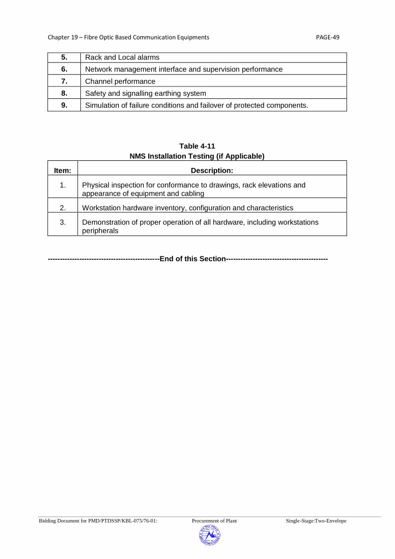
Chapter 19 – Fibre Optic Based Communication Equipments PAGE-49
Bidding Document for PMD/PTDSSP/KBL-075/76-01: Procurement of Plant Single-Stage:Two-Envelope
5. Rack and Local alarms
6. Network management interface and supervision performance
7.
Channel performance
8.
Safety and signalling earthing system
9.
Simulation of failure conditions and failover of protected components.
Table 4-11
NMS Installation Testing (if Applicable) Item:
Description:
1.
Physical inspection for conformance to drawings, rack elevations and appearance of equipment and cabling
2.
Workstation hardware inventory, configuration and characteristics
3.
Demonstration of proper operation of all hardware, including workstations peripherals
----------------------------------------------End of this Section------------------------------------------

Chapter 19 – Fibre Optic Based Communication Equipments PAGE-50
Bidding Document for PMD/PTDSSP/KBL-075/76-01: Procurement of Plant Single-Stage:Two-Envelope
Section-5
Training and Support Services
This section describes the requirements for Contractor-supplied training, support services, and maintenance of the FOTS, Terminations equipments sub-systems, etc. The intent of the training and support program is to ensure a smooth transfer of systems and technologies from the Contractor to the Employer, and to ensure that Employer staff is fully trained to operate, maintain and expand the integrated telecommunication network. 5.1 Training The Contractor shall provide a comprehensive training program that prepares the Employer’s personnel for on-site installation support, operation, and maintenance of the telecommunication network. Training may be conducted by the Contractor, the Contractor's subcontractors, and/or original equipment manufacturers (OEMs). The training requirements of this Specification shall apply to all such courses. Training courses shall be conducted by personnel who speak understandable English and who are experienced in instruction. All necessary training material shall be provided by the Contractor. Hands-on training shall be provided with equipment identical to that being supplied to the Employer. The schedule, location and detailed training contents shall be submitted by the Contractor to the Employer for approval. 5.1.1 System Design & Overview Training This training shall provide a functional description of the telecommunication subsystems for both fibre optic transmission system and Termination equipment system and a discussion of the failover and alternate routing schemes inherent in the configuration. The training shall include an overview of the network configuration and indicate the functional responsibilities of all major subsystems including the network monitoring system hardware and software. The training shall highlight all significant methodologies or concepts utilized by the hardware and software to perform the required functions. High-level hardware configuration block diagrams and network/sub-network block/flow diagrams shall be included to enhance the understanding of the overall capability incorporated into all network and sub-network equipment. The training shall be oriented to a user's point of view. The Employer/Owner users will include managers, design & planning personnel, communication support staff and maintenance person-nel. As part of the proposal, the Contractor shall identify the number of days deemed appropriate for this training. The overview training shall be customized for the specific functions, features, and equipment purchased by the Employer; it shall not be a general presentation of the Contractor' standard equipment repertoire. Personnel assigned by the Contractor to implement the Employer's system shall conduct this overview training. The Employer shall review and approve the contents of the overview training at least four (4) weeks prior to the course. 5.1.2 Installation & Maintenance Training
There shall be separate modules of the installation & maintenance training for the following systems:

Chapter 19 – Fibre Optic Based Communication Equipments PAGE-51
Bidding Document for PMD/PTDSSP/KBL-075/76-01: Procurement of Plant Single-Stage:Two-Envelope
(1) FO Transmission System Training (2) Termination Equipment System Training
The installation & maintenance trainings shall enable the Employer to be self -sufficient in preventive & restorative maintenance of the respective communications subsystems purchased by the Employer. 5.1.3 Training Course Requirements
This section describes general requirements that apply to all training courses.
5.1.3.1 Class Size
The Employer plans to send a number of participants to the training courses for a specified duration as described in Appendices.
5.1.3.2 Training Schedule
The Contractor shall provide training in a timely manner that is appropriate to the overall project schedule. All training courses shall be available to the Employer for a minimum of five years after final acceptance of the communication system. The training courses shall be offered in one cycle, such that none of the courses within the cycle overlap. The Contractor shall take the above requirements into account in developing the preliminary training schedule. Contractor shall develop a final training schedule in consultation with the Employer after contract award.
5.1.3.3 Manuals and Equipment
The Contractor, subcontractor, or OEM shall prepare training manuals and submit them to the Employer for review at least one month prior to the start of classroom instruction. The training manuals shall be prepared specifically for use as training aids; reference manuals, maintenance manuals, and user's manuals may be used as supplementary training material. Principal documents used for training shall be tailored to reflect all the Employer requirements specif ied. Each course participant shall receive individual copies of training manuals and other pertinent material at least two weeks prior to the start of each course. The Employer shall retain the master and two additional copies of all training manuals and materials as reference documentation. A complete set of instructor's manuals and training aids shall also be provided. Upon completion of each course, instructor's manuals, training manuals, and training aids shall become the property of the Employer. As part of the delivered system documentation and the final documentation, the Contractor shall supply the Employer with all changes and revisions to the training manuals and other training documentation. The Employer reserves the right to copy all training manuals and aids for use in the Employer-conducted training courses. The Contractor shall furnish for use during training courses all special tools, equipment, training aids, and any other materials required to train course participants. 5.2 Support Services

Chapter 19 – Fibre Optic Based Communication Equipments PAGE-52
Bidding Document for PMD/PTDSSP/KBL-075/76-01: Procurement of Plant Single-Stage:Two-Envelope
Throughout design, implementation, factory testing, and field installation and testing, the Contractor shall supply consulting assistance, as required by the Employer for site preparation, field installation, and other areas where technical support may be required. The Contractor shall be responsible for minor facility renovation, and maintenance of the supplied system up to and including successful completion of the Site Acceptance Test. After final acceptance of the communications equipment, the Contractor shall offer continuing technical support and spare parts for the designed life of the equipment or 7 years after the declaration of withdrawal of equipment from production whichever is earlier. However the termination of production shall not occur prior to Operational Acceptance of the system by the Employer. Some locations have existing SDH & MUX equipment. The traffic may be switched over to new fibre optic communication equipment in phase manner. The Contractor shall review the Employer existing equipment make, integration & switch over recommendation and prepare a detailed field implementation plan. 5.2.1 Technical Support
Consultation with Contractor's technical support personnel and trained field service personnel shall be readily available on a short-term/long-term basis to assist the Employer personnel in maintaining, expanding, and enhancing the telecommunication network upon expiration of the warranty period. The Contractor shall include in their offer(s), a proposal for ensuring continued technical support as stated above. 5.2.2 Contractor's Future Hardware/Software Changes The Employer shall be informed of all alterations or improvements to the hardware supplied under this Specification. The Employer shall be placed on the Contractor's mailing list to receive announcements of the discovery, documentation, and solution of hardware/software problems as well as other improvements that could be made to supply equipment. The service shall begin at the time of contract award, and shall continue for 10 years. The Contractor shall also include a subscription to the hardware subcontractors' change notification service from the time of contract award through the warranty period, with a Employer renewable option for extended periods. 5.3 Spare Parts and Test Equipment The spare parts and test equipment shall be provided for each subsystem as described below. 5.3.1 Mandatory Spare Parts Appendices provides the Mandatory Spare Parts Requirements described in subsystem sets.
The mandatory spare parts table represents the minimum spares the Contractor shall be required to supply. The subsystem set of spare parts is defined to include all equipment modules, subunits and parts required to effect replacement, repair and restoration to full operational status of a defined unit of a subsystem (i.e. SDH equipment, Primary Mux, Drop/Insert etc.)
5.3.2 Test Equipment
Appendix-B provides mandatory test equipment requirements, to be provided. The parameters / features of the mandatory equipments are enumerated in Table 5.2 below:

Chapter 19 – Fibre Optic Based Communication Equipments PAGE-53
Bidding Document for PMD/PTDSSP/KBL-075/76-01: Procurement of Plant Single-Stage:Two-Envelope
Table 5.2
S.No. Test equipment Parameter
1 SDH Analyser with Jitter and Wander Options
Equivalent to JDSU MTS 8000 or better
2 Handheld 2Mbps BER Tester Equivalent to JDSU EDT-135 or better
3 Ethernet Tester (with dual port, 10/100 ports Mbps Ethernet option, layer-1 & layer-2 functionality )
Equivalent to JDSU FST 2802 or better
In case the offered make/model of test equipment has multiple options for the parameters, the option of higher range shall be acceptable. The supplied test equipment shall be suitable for use in the high EMI/EMC environment. The Contractor shall submit performance certificate for offered test equipment from at least one customer. The Contractor shall offer only reputed make test equipment such as Acterna (JDSU)/Anirutsu/ Fluke/Agilent/EXFO etc. The Contractor shall provide in their bid, additionally recommended test equipment list necessary to support system availability figures specified in technical specifications. These lists shall include all relevant technical descriptions and recommended minimum quantities based upon the guidelines consistent with the telecommunications resource management hierarchy and continuing maintenance concept. The recommended test equipment shall not be considered for evaluation and may be included in the final scope of supply. 5.4 System Maintenance The contractor shall be responsible to maintain the confidentiality of the Employer’s System Information that Employer shares with the contractor for maintenance period.
5.4.1 Warranty Period
The one year period commencing immediately after the operational acceptance is called the Warranty Period/Defect liability Period. In addition to the responsibilities covered under contract during Defect Liability Period, the Contractor shall also be responsible for maintenance of the Fibre Optic Transmission System, Termination Equipment, etc. supplied under this Package.
5.4.2 Contractor’s Maintenance Responsibility The Contractor shall be responsible for carrying out “Comprehensive Maintenance” of the Communication System for a period of 3 years after warranty period for ensuring the successful operation of the system. The Contractor shall be responsible for achieving the system availability and the response time mentioned in technical specifications. Bidder shall submit the detailed procedure for achieving above in the bid. 5.5 Miscellaneous Supplies
The Contractor shall provide all required consumable and non-consumable supplies necessary to support all installation and test activities through final operational acceptance. However, if there are any problems in the SAT and additional consumables are required, the same shall also be supplied by the Contractor at no additional cost.

Chapter 19 – Fibre Optic Based Communication Equipments PAGE-54
Bidding Document for PMD/PTDSSP/KBL-075/76-01: Procurement of Plant Single-Stage:Two-Envelope
5.6 Documentation
The Contractor shall submit following documents during detailed engineering:
(a) Data Requirement sheets (b) Link Budget calculations (c) MQP, FQP (d) Bill of Quantity including mandatory spares (e) Previous Type test reports (f) Factory Test report (g) Manuals for each equipment (h) Schematic drawing (i) Numbering, Marking, labelling document (j) Synchronization plan (k) Test schedule (l) Training manual (m) Configuration diagram (n) Transportation & handling Procedure (o) Installation Manuals (p) Maintenance Manuals
----------------------------------------------End of this Section-----------------------------------------

Chapter 20 – LT Transformer PAGE-1
Bidding Document for PMD/PTDSSP/KBL-075/76-01: Procurement of Plant Single-Stage:Two-Envelope
CHAPTER 20: LT TRANSFORMER
1.0 INTENT
This specification is intended to cover outdoor type oil filled 33/0.400KV, 630 kVA transformer.
2.0 SCOPE OF WORK
2.1 Scope of Supply
- Transformers as listed above, with insulating oil, all materials and accessories, and
complete in all respects. - Gland plates, power cable, lugs, anchor bolts and hardwares. - Mandatory & optional spares and special maintenance equipments if any. 2.2 Scope of Service
The scope includes but is not limited to the following items of work to be performed for all
equipment and materials furnished under this chapter: a) Design, manufacturing, shop testing, packing & despatch b) Transportation inclusive of insurance and delivery, FOR site basis c) Unloading, handling, storing, transportation at site up to foundations, oil filling and
treatment, erection, testing and commissioning d) Civil Works e) Supply of external cables and termination as required. f) Fire protection system. 3.0 GENERAL INFORMATION
3.1 All temperature indicators, Buchholz relays and other auxiliary devices shall be suitable for
220 V DC Control supply. All alarm and trip Contacts shall also be suitable for connection in 220V DC Circuits.
3.2 Bidders may specifically note that transformers offered shall conform to dynamic short
circuit test and dielectric test as per IEC: 60076. Test report for the same shall be submitted during detail engineering for approval.
4.0 TECHNICAL REQUIREMENTS

Chapter 20 – LT Transformer PAGE-2
Bidding Document for PMD/PTDSSP/KBL-075/76-01: Procurement of Plant Single-Stage:Two-Envelope
4.1 Core The core shall be constructed from high grade, non-aging, cold rolled grain-oriented silicon
steel laminations. The maximum flux density in any part of the cores and yoke at normal voltage and frequency shall be such that the flux density at any tap position with 10% voltage variation from the voltage corresponding to the tap shall not exceed 1.9 Wb/sq-m.
4.2 Windings The conductor shall be of electrolytic copper, free from scales and burrs. 4.3 Insulating Oil
The oil supplied with transformer shall be unused and have the parameters for unused new
oil conforming to IEC: 60296 while tested at oil Contractor's premises, No inhibitors shall be used in oil. Ten percent extra oil shall be supplied for topping up after commissioning in nonreturnable containers suitable for outdoor storage.
4.4 Terminal Arrangement
a) Bushing terminals shall be provided with suitable terminal connectors of approved
type and size for cable/overhead conductors termination of HV side and cable termination on LV side.
b) The neutral terminals of 400V winding shall be brought out on a bushing along with
the 433 volt phase terminals to form a 4 wire system for the 400 volt. Additional neutral bushing shall also be provided for earthing.
4.5 Off Circuit Tap Changing Equipment
The tap change switch shall be three phase, hand operated for simultaneous switching of
similar taps on the three phases by operating an external hand wheel. 4.6 Marshalling Box
A metal enclosed, weather, vermin & dust proof marshalling box shall be provided with
each transformer to accommodate temperature indicators, terminal blocks etc. It shall have a degree of protection of IP 55 as per IEC: 60947 Part-1.
4.7 Cable boxes
Whenever cable connections are required, suitable cable boxes shall be provided and shall
be air insulated. They shall be of sufficient size to accommodate Purchaser's cables and

Chapter 20 – LT Transformer PAGE-3
Bidding Document for PMD/PTDSSP/KBL-075/76-01: Procurement of Plant Single-Stage:Two-Envelope
shall have suitable removable side/top cover to facilitate cable termination and inspection. Cable boxes shall be dust & vermin proof.
5.0 INSPECTION AND TESTING
a) The Contractor shall draw up and carry out a comprehensive inspection and testing
program during manufacture and commissioning of the transformer. The programme shall be duly approved by the Purchaser.
b) The Contractor shall carryout all routine tests on all the transformers as per relevant
standards. Type test report shall be submitted for approval during detail engineering.
6.0 INSPECTION
6.1 Tank and Accessories a) Physical and dimensional check of transformer tank and accessories. b) Crack detection of major strength weld seams by dye penetration test. 6.2 Core
a) Physical inspection and check of quality of varnish, if used. b) Sample testing of core material for checking specific loss, bend properties,
magnestisation, characteristics and thickness. c) Check on completed core for measurement of iron loss and check for any hot spot
by exciting the core so as to induce the designed value of flux density in the core. d) HV Test
6.3 Insulating Material
a) Sample checks for physical properties of the material b) Check for dielectric strength c) Check for the reaction of hot oil on insulating material 6.4 Winding

Chapter 20 – LT Transformer PAGE-4
Bidding Document for PMD/PTDSSP/KBL-075/76-01: Procurement of Plant Single-Stage:Two-Envelope
a) Sample check on winding conductor for mechanical properties and electrical conductivity and on installation covering.
b) Sample check on insulation paper for pH value, Bursting strength, Electric strength. 6.5 Assembled Transformer
a) Check complete transformer against approved outline drawing provision for all fittings, finish etc.
b) Jacking test on all the assembled transformers.
6.6 Oil
All Standard tests in accordance with relevant Standards shall be carried out on oil
samples taken from the transformer before and after testing of the transformer. The contractor shall also prepare a comprehensive inspection and testing programme for
all bought out sub-contracted items and shall submit the same to the Purchaser for approval. Such programme shall include the following components:
a) Buchholz Relay b) Winding temperature Indicator c) Bushings d) Marshaling Box e) Tap changer switch f) Oil temperature indicator 7.0 FACTORY TEST 7.1 All standard routine tests in accordance with latest issue of IEC: 60076 shall be carried out
on each transformer. 7.2 The transformer shall conform to all the type tests in accordance with latest issues of IEC:
60076. The manufacturer shall submit type tests & additional test reports as listed above as already carried out on transformers of identical design for owner’s acceptance. In such a case validity of type test reports shall be in line with clause 9.2 of Chapter 2-GTR of technical specifications. Following parameters in general shall be ensured for establishment of identical design as per IEC 60076, Part-V.
a) Same Voltage ratio, KVA rating, vector group & impedance. b) Same conceptual design of core and winding. c) Same arrangement and geometrical sequence of the main windings. d) Same type of winding conductors. e) Same type of main windings.

Chapter 20 – LT Transformer PAGE-5
Bidding Document for PMD/PTDSSP/KBL-075/76-01: Procurement of Plant Single-Stage:Two-Envelope
f) Absorbed power at short circuit (ie rated power/per unit short circuit impedance) between 30% and 130% of that relating to the reference transformer.
g) Axial forces and winding stresses occurring at short circuit not exceeding 120% of those relating to the reference transformer.
h) Same manufacturing process. i) Same Clamping and winding support arrangement..
7.3 In addition to all type and routine tests, transformer shall also conform to following
additional type tests as per IEC: 60076.
a) Measurement of zero sequence impedance b) Short circuit test c) Measurement of acoustic noise level. This shall conform to NEMA standard
publication TR-1. d) Measurement of capacitance and tan delta of transformer winding. e) Test on oil samples as per equivalent international standard.
7.4 All auxiliary equipment shall be tested as per the relevant Test Certificates shall be
submitted for bought out items. 7.5 High voltage withstand test shall be performed on auxiliary equipment and wiring after
complete assembly. 7.6 Tank Tests: i) Routine Tests: As per IEC: 60076 Part-1 including ii) Vacuum Tests: As per IEC: 60076 Part-1 iii) Pressure Test: As per IEC: 60076 Part-1 7.7 In addition to the above, the following checks should be carried out at manufacturer's
works before despatch for all transformers:
a) Check for interchangeability of components of similar transformers and for mounting dimensions.
b) Check for proper packing and preservation of accessories like radiators, bushings
explosion vent, dehydrating breather, Buchholz relay, conservator etc. c) Check for proper provision of bracings to arrest the movements of core and winding
assembly inside the tank.

Chapter 20 – LT Transformer PAGE-6
Bidding Document for PMD/PTDSSP/KBL-075/76-01: Procurement of Plant Single-Stage:Two-Envelope
d) Test for gas tightness and derivation of leakage rate. To ensure adequate reserve gas capacity during transit and storage.
7.8 The Contractor shall submit a detailed inspection and testing programme for field activities,
covering areas right from the receipt of material stage upto commissioning stage as per equivalent international standard - Code of practice for installation and maintenance of transformers. The indicative checks and tests are given below.
a) Physical checks on each transformer on receipt at site for any damage or short
supply. b) Tests on oil samples c) Oil leakage test d) Physical checks for colour of silica in breather e) Check for oil level in breather housing, conservator tank, etc. f) Check for correct operation of all protections and alarms. g) Insulation Resistance Measurement for Main Winding, control wiring etc. h) Continuously observe the transformer operation at no load for 24 hours. 8.0 FITTINGS The following fittings shall be provided with each transformer covered under this
specification. i) Conservator with drain plug and oil filling hole with blanking plate ii) Plain oil Gauge iii) Silica gel Breather iv) Pressure Relief vent v) Pocket on tank cover for Thermometer vi) Valves vii) Earthing Terminals viii) Rating & Terminal Marking Plates ix) Lifting Lugs x) Rollers xi) Air Release Plug The fittings listed above are only indicative and any other fittings which generally are
required for satisfactory operation of transformer are deemed to be included. 9.0 SPARE PARTS 9.1 The list of spares for outdoor type transformers covered under this chapter shall be as
specified in Chapter 1- PSR 9.2 In addition, the Bidder shall also recommend optional spare parts and maintenance
equipment necessary for three (3) years of successful operation of the equipment. The
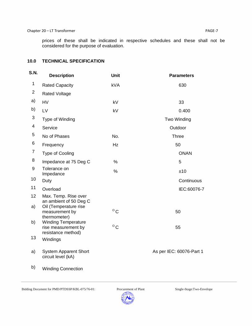
Chapter 20 – LT Transformer PAGE-7
Bidding Document for PMD/PTDSSP/KBL-075/76-01: Procurement of Plant Single-Stage:Two-Envelope
prices of these shall be indicated in respective schedules and these shall not be considered for the purpose of evaluation.
10.0 TECHNICAL SPECIFICATION
S.N.
Description Unit Parameters
1 Rated Capacity kVA 630
2 Rated Voltage
a) HV kV 33
b) LV kV 0.400
3 Type of Winding Two Winding
4 Service Outdoor
5 No of Phases No. Three
6 Frequency Hz 50
7 Type of Cooling ONAN
8 Impedance at 75 Deg C % 5
9 Tolerance on Impedance
% ±10
10 Duty Continuous
11 Overload IEC:60076-7
12 Max. Temp. Rise over an ambient of 50 Deg C
a) Oil (Temperature rise measurement by thermometer)
O C 50
b) Winding Temperature rise measurement by resistance method)
O C 55
13 Windings
a) System Apparent Short
circuit level (kA)
As per IEC: 60076-Part 1
b) Winding Connection

Chapter 20 – LT Transformer PAGE-8
Bidding Document for PMD/PTDSSP/KBL-075/76-01: Procurement of Plant Single-Stage:Two-Envelope
S.N. Description Unit Parameters
(i) HV Delta
(ii) LV Star
14 Vector Group Dyn1
15 Insulation Uniform
16 Insulation Level kVrms
a) Power Frequency Test Level
(i) HV kVrms 95
(ii) LV kVrms 2
17 Basic Impulse Level
(i) HV kVp 250
(ii) LV kVp -
18 Highest voltage (kV) for each winding
kV 52
19 Method of earthing Solidly earthed
20 Tap changer
a) (i) Tap Change
+5% to -10% in step of 2.5% on HV side
b) (ii) Tap control Off Circuit Tap Change Switch
21 HV Bushing
a) Rated Voltage kV 52
b) Rated current A 100
c) Basic Impulse Level (kVp)
kVp 250
d) Wet & Dry Power frequency Withstand Voltage
kVrms 95
e) Min. Total Creepage Distance
mm 1300
f) Mounting Tank / Transformer Body
22 LV & Neutral Bushing

Chapter 20 – LT Transformer PAGE-9
Bidding Document for PMD/PTDSSP/KBL-075/76-01: Procurement of Plant Single-Stage:Two-Envelope
S.N. Description Unit Parameters
a) Rated Voltage kV 1.1
b) Rated current A 1000
c) Basic Impulse Level (kVp)
kVp -
d) Wet & Dry Power frequency Withstand Voltage
kVrms 2
e) Mounting Tank / Transformer Body
23 Terminal Details
a)
HV Suitable for 33kV Cable or Over Head Conductor
b) LV & Neutral Cable Box
24 Min. Clearance in Air mm
a) Ph-Ph (HV/LV) mm 530/25
b) Ph-Earth (HV/LV) mm 480/25

Chapter 21 –Drawings PAGE-1
Bidding Document for PMD/PTDSSP/KBL-075/76-01: Procurement of Plant Single-Stage:Two-Envelope
Chapter 21- Drawings
LIST OF DRAWINGS
S. No. DRAWING NO. TITLE
A) 400/220kV New Khimti Substation
1. KHIMTI-GIS-SLD-1 Single Line diagram of 400/220 kV New Khimti Substation
2. KHIMTI-GIS-LAYOUT-2(A)
KHIMTI-GIS-LAYOUT-2(B)
General arrangement/Layout plan drawing of 400/220
New Khimti Substation
B) 400/220kV Barhabise Substation
1. BARHABISE-GIS-SLD-1 Single Line diagram of 400/220kV Barhabise Substation
2. BARHABISE-GIS-LAYOUT-2(A)
BARHABISE-GIS-LAYOUT-2(B)
General arrangement/Layout plan drawing of 400/220kV
Barhabise Substation
C) 400/220kV Lapsiphedi Substation
1. LAPSIPHEDI-GIS-SLD-1 Single Line diagram of 400/220kV Lapsiphedi Substation
2. LAPSIPHEDI-GIS-LAYOUT-2(A)
LAPSIPHEDI-GIS-LAYOUT-2(B)
General arrangement/Layout plan drawing of 400/220kV
Lapsiphedi Substation
D) NEA-KBL-CTS-05 OF 05 ( 1 to 5 ) Detail for cable trench sections
E) NEA-KBL-DR-02 OF 02 ( 1 to 2 ) Detail for drain sections
F) NEA-KBL-SF-01 OF 01 Standard details for switch yard chain link fencing
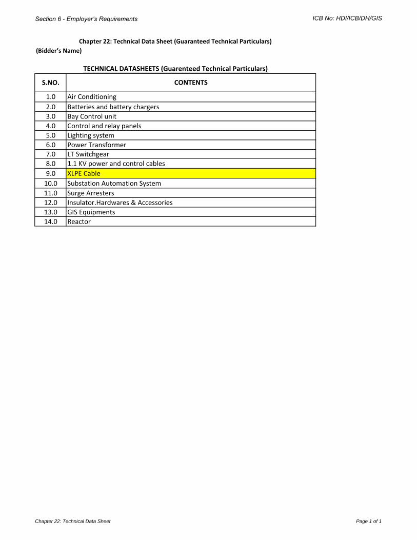
Section 6 - Employer’s Requirements ICB No: HDI/ICB/DH/GIS
(Bidder’s Name)
S.NO. CONTENTS
1.0 Air Conditioning
2.0 Batteries and battery chargers
3.0 Bay Control unit
4.0 Control and relay panels
5.0 Lighting system
6.0 Power Transformer7.0 LT Switchgear
8.0 1.1 KV power and control cables
9.0 XLPE Cable
10.0 Substation Automation System
11.0 Surge Arresters
12.0 Insulator.Hardwares & Accessories
13.0 GIS Equipments
14.0 Reactor
TECHNICAL DATASHEETS (Guarenteed Technical Particulars)
Chapter 22: Technical Data Sheet (Guaranteed Technical Particulars)
Chapter 22: Technical Data Sheet Page 1 of 1

Chapter 22: Technical Data Sheet Air Conditioning Page 1 of 1
(Bidder’s Name)
1.0
Sl.No Description Offered Data
1 Manufacturer’s Name & Model
2 Star Rating
3 Compressor Cooling capacity
4 Rated current -cooling
5 Rated Power input- cooling
6 Rated EER
7 Power Supply
8 Air Flow Volume- Indoor
9 Noise level - Indoor
10 Operation
11 Compressor type
a)Compressor make
b)Compressor sealed
12 Refrigerant
13 Indoor unit Dimension (WxHxD)
14 Indoor unit Net/Gross weight
15 Outdoor unit Dimension (WxHxD)
16 Outdoor unit Net/Gross weight
17 Connecting Pipe with Cable
18 Length
19 Connecting Box Dimension (WxHxD)
20 No of Boxes
a)ODU
b)Connecting pipe
c)IDU
21 Features
a)Filters
b)Coil
c)Copper tubes
d)IDU
e)Remote
Date______________________________________
AIR CONDITIONING
Signed ____________________
As representative for _________________________
Address _______________________________________
Bidding Document for PMD/PTDSSP/KBL-075/76-01 Procurement of Plant Single-Stage:Two-Envelope

Chapter 22: Technical Data Sheet Battery Battery Charger Page 1 of 1
(Bidder’s Name)
2.0
220V 48V
A. BATTERIES1.0 Manufacturer’s Name & address
2.0
Confirm whether Manufactures have
Manufactured, tested, supplied, installed and
commissioned batteries of 220V, 600AH, capacity
similar to the offered batteries and are in operation
for at least 2(Two) years
3.0 Type of battery
4.0 Capacity of battery at 27°C
5.0 Whether batteries are type tested as per IEC
6.0 Recommended value of float charging voltage
B. BATTERY CHARGERS
1.0 Manufacturer’s Name & address
2.0
Confirm whether Manufactures have
Manufactured, tested, supplied, installed and
commissioned battery chargers of 10 KW capacity
similar to the offered battery charger
3.0 Capacity of battery charger (AH)
4.0 Charger rate/output current
5.0 Float charging mode (A)
6.0 Boost charging mode (A)
7.0 Ripple content in output voltage %
8.0Confirm whether battery chargers are type tested
as per specification
Signed ____________________
As representative for _________________________
Address _______________________________________
Date______________________________________
BATTERIES
Sl.No DescriptionOffered Data
Bidding Document for PMD/PTDSSP/KBL-075/76-01 Procurement of Plant Single-Stage:Two-Envelope

Chapter 22: Technical Data Sheet Bay Control Unit Page 1 of 1
(Bidder’s Name)
3.0 BAY CONTROL UNIT
Sl.No Description Offered Data
1.0 Name of Manufacturer
2.0 Type of unit Mounting
3.0 Manufacturer’s type designation
4.0 Standards Applicable
5.0 Rated Auxiliary Voltage
6.0 No. of analogue variable (Specify Voltage
& Current Separately)
7.0 Rated frequency (Hz)
8.0 No. of binary inputs
9.0 No. of output
10.0 Language
11.0 Type of communication protocol supported
by unit
12.0 No. & Type of communication ports
13.0 Operating temperature range
14.0 System response time
14.1 Exchange of display
14.2 Presentation of Binary Change
14.3 Presentation of Analogue Change
14.4 Order to process output
14.5 Order to update display
14.6 Report Generation
Signed ____________________
As representative for _________________________
Address _______________________________________
Date______________________________________
Bidding Document for PMD/PTDSSP/KBL-075/76-01 Procurement of Plant Single-Stage:Two-Envelope

Chapter 22: Technical Data Sheet Control Relay Panel Page 1 of 5
(Bidder’s Name)
4.0
Sl.No Description Offered Data
1 Name and address of Manufacturer of panels
2 Manufacturer's type and designation
3 Type of construction (Simplex/duplex)
4 Thickness of sheet steel
(i)Front
(ii)Back
(iii)Sides
5 Degree of protection
6 Name of the manufacturer of relays
7 DC voltage of the relays
8Make and Model of static ( 0.2 accuracy class type) energy
meters
9
Confirm whether offered manufacturer of C&Rpanels and
protective relays have tested commissioned & they are in
successful operationfor at least five years in 132 kV system
I TRANSMISSION LINE PROTECTION
A Numerical Distance protection Scheme
1 Name and address of Manufacturer
2 Manufacturer's type and designation
3Switched or Non- switched type ( is it with separate
measurements for single/three phase faults)
4 Setting range of offset feature
5 Whether the relay is having self monitoring feature
6
Whether relay is compatible for Optical Fiber equipment
and can be used for Permissive Under reach/over reach
/Blocking scheme etc
7 Suitable for single and three phase Trip?
8 Type of shaped characteristic
9No of tripping contacts with making capacity of 30 amp for
0.2 seconds
10In case 16 contacts as per above clause are not available
with the distance relay offered , type of tripping relay being
offered 11
Maximum operating time for at 50% of the reach setting of
2 ohms and 10/20 ohms (with CVT) including all trip relays
,if any (Bidder is required to enclose isochronic curve with
CONTROL AND RELAY PANELS
Bidding Document for PMD/PTDSSP/KBL-075/76-01 Procurement of Plant Single-Stage:Two-Envelope

Chapter 22: Technical Data Sheet Control Relay Panel Page 2 of 5
(Bidder’s Name)
4.0
Sl.No Description Offered Data
CONTROL AND RELAY PANELS
a)at SIR=4
b)at SIR=15, (3 phase faults)
c)at SIR=15 (other faults)
12
IDMT earth fault relay Meeting Normal Inverse
Characteristics as per IEC 60253 is being offered as built in
feature for 220 KV lines
13 If no, type of IDMT relay being offered
14 Built in features offered with the relay (YES/NO)
a)Disturbance recorder
b)Fault locator
c)Over voltage (one stage only)
d)Auto reclose along with Dead line charging and check
synchronisng
BBACKUP DIRECTIONAL OVER CURRENT AND EARTH
FAULT PROTECTION SCHEME
1 Name and address of Manufacturer
2 Manufacturer’s type and designation
3Three over current and one E/F elements Are whether
independent or composite unit
4 Type of relay (Elecromechanical /static/Numerical)
5 Directional sensitivity
6 Whether characteristic conform to IEC 255-3
7 Over current unit setting range inverse time
8 Earth fault unit setting range inverse time
9 VT Fuse failure relay/ feature included for alarm
C LINE OVER VOLTAGE PROTECTION RELAY
1 Name and address of Manufacturer
2 Manufacturer’s type and designation
3 Type of relay (Elecromechanical /static/Numerical)
4 Operation indicator provided?
5 Operating time
6 Resetting time
7 Whether monitors all three phases?
8Built in feature of Main1/Main 2 distance relay is offered. If
so , which stage is offered as built in
D DISTANCE TO FAULT LOCATOR
1 Name and address of Manufacturer
2 Manufacturer’s type and designation
3 Built in feature of Main1/Main 2 distance relay is offered
4 Maximum registering time
5 Whether direct display unit provided?
6Whether both phase to phase fault and phase to earth fault
measuring units included?
7 Whether “On-Line” type
8Accuracy for the typical conditions defined under technical
specification
Bidding Document for PMD/PTDSSP/KBL-075/76-01 Procurement of Plant Single-Stage:Two-Envelope

Chapter 22: Technical Data Sheet Control Relay Panel Page 3 of 5
(Bidder’s Name)
4.0
Sl.No Description Offered Data
CONTROL AND RELAY PANELS
F DISTURBANCE RECORDER
a. Acquisition unit
1 Name and address of Manufacturer
2 Manufacturer's type and designation
3 No. of analogue channels
4 No. of digital recording channels
7 Built in feature of Main1/Main 2 distance relay is offered
6 Pre-fault memory (milli seconds)
7 Post fault memory(seconds)
8 Total storage memory in seconds
9 Sampling frequency
10 Resolution of event channels
11 Time display present?
12 Data output in comtrade is available?
1 Name and address of Manufacturer
2 Manufacturer's type and designation
3No of acquisition unit that can be connected to One
evaluation unit
4 Technical Parameters of evaluation unit
A Processor and speed
B RAM and hard disk capacity
C Additional facilities
D Details of printer
5Details of power supply arrangement for Acquisition unit
(including printer)
G AUTO RECLOSE RELAY
1 Name and address of Manufacturer
2 Manufacturer's type and designation
3 Electromechanical /static/numerical
4
Auto reclose relay along with Dead line charging and check
synchronizing relay (For 132 KV lines) offered as a part of
distance relay
5 Suitable for single and three phase?
6 Single phase dead time setting Range
7 Three phase dead time setting range
8 Reclaim time setting range
II TRANSFORMER PROTECTION
A Differential relay
1 Name and address of Manufacturer
2 Manufacturer's type and designation
3 Second harmonic restraint provided
4 Whether three instantaneous units provided
5 Operating Current setting range
6 Bias setting range
7 Operating time at 5X setting current
8 Resetting time
b. Evaluation Unit
Bidding Document for PMD/PTDSSP/KBL-075/76-01 Procurement of Plant Single-Stage:Two-Envelope

Chapter 22: Technical Data Sheet Control Relay Panel Page 4 of 5
(Bidder’s Name)
4.0
Sl.No Description Offered Data
CONTROL AND RELAY PANELS
9How ratio / phase angle corrections are being done (inter
posing transformer/internal feature in the relay)
B
1 Name and address of Manufacturer
2 Manufacturer's type and designation
3 Operating time at 2 X setting
C
1 Name and address of Manufacturer
2 Manufacturer's type and designation
3 Whether inverse time operating characteristics
4 Maximum operating time
5 Accuracy of operating time
6 Resetting time
D Directional O/C and E/F relays
1 Name and address of Manufacturer
2 Manufacturer's type and designation
3 Whether Characteristic will confirm to IEC255-3
4 Directional sensitivity
5 Over current unit setting range
a) Inverse time
b) High set
6 Earth fault unit setting range
a) Inverse time
b) High set
GENERAL PROTECTION /MONITORING EQUIPMENT
Trip Circuit Supervision relay
1 Name and address of Manufacturer
2 Manufacturer's type and designation
3 Whether pre-closing and post closing supervision provided?
4 Time delay
High Speed Trip Relays
1 Name and address of Manufacturer
2 Manufacturer's type and designation
3 Contact ratings
a) Make and carry continuously
b) Make and carry for 0.5 sec.
c) Break
i). Resistive load
ii) Inductive load (With L/R=40milli sec.)
4 Operating time at rated voltage(maximum)
5 Resetting time
6 Whether supervisory relays included
E Local breaker back-up protection
1 Name and address of Manufacturer
2 Manufacturer's type and designation
Restricted Earth Fault Protection
Over Fluxing relays
Bidding Document for PMD/PTDSSP/KBL-075/76-01 Procurement of Plant Single-Stage:Two-Envelope

Chapter 22: Technical Data Sheet Control Relay Panel Page 5 of 5
(Bidder’s Name)
4.0
Sl.No Description Offered Data
CONTROL AND RELAY PANELS
3 Operating time
4 Resetting time
5 Setting ranges
a) Current
b) Time
III Bus bar Protection
1 Name and address of Manufacturer
2 Manufacturer's type and designation
3 Type of relay (Elecromechanical /static/Numerical)
4 Principle of operation (Biased/High impedance)
5 Operating time
6 Resetting time
7 Setting ranges
i)Current
ii)Time
8
Whether will it cause tripping for the differential current
below the load current of heavily loaded feeder (Bidder
shall submit application check for the same)
Date______________________________________
Signed ____________________
As representative for _________________________
Address _______________________________________
Bidding Document for PMD/PTDSSP/KBL-075/76-01 Procurement of Plant Single-Stage:Two-Envelope

Chapter 22: Technical Data Sheet Lighting System Page 1 of 1
(Bidder’s Name)
5.0 LIGHTING SYSTEM
Sl. No Description Offered Data
A. LIGHTING FIXTURES & ACCESSORIES
1.0 Manufacturer’s Name & address
a) Fixtures
b) Accessories
2.0 Applicable Standards for
a) Fixtures
b) Accessories
Maximum permissible supply voltage variation for satisfactory
operation of
a) Fixtures
b)Accessories
B. CONDUIT & ACCESSORIES (FOR EACH TYPE & SIZE)
1.0 Manufacture’s Name & address
2.0 Manufacturer’s type, designation
3.0 Applicable standard
C. JUNCTION BOXES (FOR EACH TYPE & SIZE)
1.0 Manufacture’s Name & address
2.0 Manufacturer’s type, designation
3.0 Type of enclosure
D. LIGHTING PANELS (FOR EACH TYPE & SIZE)
1.0 Manufacture’s Name & address
2.0 Type
3.0 Degree of Protection
E LIGHTING TRANSFORMER
1.0 Manufacture’s Name & address
2.0 Type
3.0 Rating
4.0 Standards Applicable
5.0 Degree of protection for Enclosure
F LIGHTING POLES
1.0 Manufacture’s Name & address
2.0 Type
3.0 Dimension
G. LIGHTING WIRES
1.0 Manufacture’s Name & address
2.0 Voltage Grade
3.0 Cross section of conductor
4.0 Insulation Thickness
Signed ____________________
As representative for _________________________
Address _______________________________________
Date______________________________________
4.0.
Bidding Document for PMD/PTDSSP/KBL-075/76-01 Procurement of Plant Single-Stage:Two-Envelope

Chapter 22: Technical Data Sheet Transformer Page 1 of 6
(Bidder’s Name)
6.0 Power TransformerOffered Data Offered Data
S.N. Bidders/ Description
105MVA, 1-phase,
400/√3/220/√3/33 KV
53.33MVA, 1-phase,
400/√3/220/√3/33 KV
1 Name of manufacturer
2 Normal full load single phase/three phase output:
H.V. Winding (KVA)
L.V. Winding (KVA)
2.1 Temp. Rise as specified in the specification.
3Continuous single phase/three phase output under, Site conditions as
specified in the specification
H.V. Winding (KVA)
L.V. Winding (KVA)
4 Type of cooling and corresponding normal Full load output
H.V. Winding (KVA)
L.V. Winding (KVA)
5Over load capacity starting from Full load and with Temp. as
specified in the Specification (KVA)
6 Normal ratio of transformation
7 Connection (including vector group reference & Symbol)
H. V. Winding
L.V. Winding
8 Type of tap changer
9 Tapping
a) Number
b) Range
c) Location
10 Details of Automatic Voltage Regulator
(a) Make
(b) Model etc.
(c) Short description (other)
11 Type of core construction
12 i) Temp. rise by resistance of winding (ºC)
ii) Temp. rise in oil by thermometer (ºC)
iii) Hot spot temp. for which the transformer is designed (ºC)
13 Limit for hot spot temp. for which the transformer is designed (ºC)
14 Guaranteed no load loss at rated voltage & rated frequency and
75ºC average winding temperature
15
Guaranteed load losses at rated current rated voltage, rated
frequency and 75 ºC average winding temp. KW (excluding
auxiliary losses)
for ONAN cooling
for ONAF cooling
for ODAF cooling
16 a) Auxiliary losses at rated output – KW
b) Total losses at normal ratio, rated output, rated voltage, rated
frequency and maximum attainable temp. at site including auxiliary
losses – KW
(c) Stray eddy losses as % of total losses
17 Exciting current power factor (Amp. %)
i) At normal voltage & frequency
ii) At maximum voltage and normal frequency
18 Efficiency at 75 ºC Unity P.F.
i) On 100% load (%)
ii) On 75% load (%)
Bidding Document for PMD/PTDSSP/KBL-075/76-01 Procurement of Plant Single-Stage:Two-Envelope

Chapter 22: Technical Data Sheet Transformer Page 2 of 6
(Bidder’s Name)
6.0 Power TransformerOffered Data Offered Data
S.N. Bidders/ Description
105MVA, 1-phase,
400/√3/220/√3/33 KV
53.33MVA, 1-phase,
400/√3/220/√3/33 KV
iii) On 50% load (%)
iv) On 25% load (%)
19 Efficiency at 75 ºC 0.8 P.F. (Lag)
i) On 100% load (%)
ii) On 75% load (%)
iii) On 50% load (%)
iv) On 25% load (%)
v) Load at which maximum efficiency occurs (% of full load)
20 Maximum efficiency (%)
21 a) Percentage reactance at rated current and frequency
b) Percentage impedance at rated current and frequency at 75 ºC
i) Positive sequence
ii) Zero sequence
c) Range of variation (+,-) offered
d) Tolerance applicable if any
22Impedance voltage drop at normal ratio at 75ºC expressed as a
percentage of normal voltage on full load (%)
23Regulation on full load at unity P.F. at 75 ºC expressed as a
percentage of normal voltage (%)
24Regulation on full load 0.8 P.F. lagging at 75ºC expressed as a
percentage in the winding
25Maximum current density & c/s area in the winding (Guaranteed
and As per SC calculation)
i) H.V. (Amp./Sq. cm.)
ii) Cross sectional area
iii) L.V. (Amp/Sq. cm)
iv) Cross sectional area
26 Maximum flux density in the core
26.a Core details
i) Material of core lamination
ii) Thickness of core plates (mm)
iii) Insulation of core lamination
iv) Insulation of core clamping plates
v) Press board material & thickness
vi) Prime quality grade
27 Core joints (butt or inter leave)
28 Type of winding
i) H.V.
ii) L.V.
29 Type of radial support
i) High Voltage Winding
ii) Lower Voltage Winding
30 Insulation of higher voltage winding
31 Insulation of lower voltage winding
32 Thickness of transformer tank plates
i) Sides (mm)
ii) Bottom (mm)
iii) Cover (mm)
Bidding Document for PMD/PTDSSP/KBL-075/76-01 Procurement of Plant Single-Stage:Two-Envelope

Chapter 22: Technical Data Sheet Transformer Page 3 of 6
(Bidder’s Name)
6.0 Power TransformerOffered Data Offered Data
S.N. Bidders/ Description
105MVA, 1-phase,
400/√3/220/√3/33 KV
53.33MVA, 1-phase,
400/√3/220/√3/33 KV
iv) Radiator (mm)
33 (A) POWER FREQUENCY WITHSTAND VOLT
i) Test voltage for 1 min. P.F. withstand test on live end of high
voltage winding (KV rms)
ii) Test voltage for 1 min. P.F. withstand test on neutral end of high
voltage winding (KV rms)
iii) Test voltage for 1 min. P.F. withstand test on live end of low
voltage winding (KV rms)
(B) IMPULSE TEST
i) Test voltage for 1.2/50 micro sec. Full wave withstand test on
high voltage winding (KV crest) on
ii) Test voltage for 1.2/50 micro sec. Full wave withstand test on
low voltage winding (KV crest) on
34 Inter-turn Insulation
i) Extent of end turns reinforcement
ii) Extent of reinforcement of turns adjustment to tap
iii) Test voltage for 1 min. 50 Hz. Inter-turn insulation test on (i)
(KV rms)
iv) Test voltage for 1 min. 50 Hz. inter-turn insulation test on (ii)
(KV rms)
v) Test voltage for 1 min. 50 Hz. inter-turn insulation test on main
body of the winding (KV rms)
35 Type of winding temperature indicator
36 Maxi continuous ratings
i) At 50 C ambient air temp. at site (KVA)
ii) At 40 C ambient air temp. at site (KVA)
iii) At 30 C ambient air temp. at site (KVA)
iii) At 20 C ambient air temp. at site (KVA)
37 Details of Air cell
Make
Type
Capacity
Size
38 Width of track gauge (Meters)
39 Bushing Particulars
(a) HV Bushing
i) Type of high voltage bushing and creepage distance in mm
ii) Rated current
iii) STC rating for 3 sec
iv) Weight of high voltage bushing in Kg
v) Quantity of oil in one high voltage bushing Insulator, in litre
vi) Dry 1 minute power frequency test voltage value of high voltage
bushing in KV
vii) Wet 10 second power frequency test voltage value of high
voltage bushing in KV
viii) Impulse withstand test voltage value with 1.2/50 microsecond
full wave of high voltage bushing in KV
(b) LV Bushing
i) Type of low voltage bushing and creepage distance in mm
Bidding Document for PMD/PTDSSP/KBL-075/76-01 Procurement of Plant Single-Stage:Two-Envelope

Chapter 22: Technical Data Sheet Transformer Page 4 of 6
(Bidder’s Name)
6.0 Power TransformerOffered Data Offered Data
S.N. Bidders/ Description
105MVA, 1-phase,
400/√3/220/√3/33 KV
53.33MVA, 1-phase,
400/√3/220/√3/33 KV
ii) Rated current
iii) STC rating for 3 sec
iv) Weight of low voltage bushing in Kg
v) Quantity of oil in one low voltage bushing Insulator, in litre
vi) Dry 1 minute power frequency test voltage value of low voltage
bushing in KV
vii) Wet 10 second power frequency test voltage value of low
voltage bushing in KV
viii) Impulse withstand test voltage value with 1.2/50 microsecond
full wave of low voltage bushing in KV
(c) NEUTRAL Bushing
i) Type of low voltage bushing and creepage distance in mm.
ii) Rated current
iii) Weight of bushing insulator in kg
iv) Quantity of oil in one bushing in litres
v) Dry 1 minute power frequency withstand and test voltage value
of bushing in KV
vi) Wet 10 second power frequency withstand test voltage value of
bushing in KV
vii) Impulse withstand test voltage with 1.2/50 microsecond fall
wave of bushing in KV
40 Clearance
a) Minimum clearance between phase (Mtrs.)
i) In oil
ii) Out of oil
b) Minimum clearance of high voltage to earth in oil (Mtrs)
c) Minimum clearance of high voltage to tank in oil (Mtrs)
41 Net weight of the core (Kgs.)
42 Net weight of copper (Kgs.)
a) H.V. (Kgs.)
b) L.V. (Kgs.)
c) Total (Kgs.)
43 Weight of core and windings
44 Weight of fittings
45 Net untanking weight(Kgs.)
46 Weight of tank and cover (Kgs.)
46.1 Tank dimensions
46.2 Guarantee against leakage for 3 years
47Weight of oil in transformer including bushings, conservator and
cooling system (Kgs.)/Quantity (Ltrs.)
48 Weight of oil in transformer (including bushings) (Kgs)
49 Weight of complete transformer with oil and all fittings (Kgs.)
50 Weight of transformer with all fittings but without oil (Kgs.)
51 Weight of the package to be transported and dimensions
52 Dimensions of the transformers
i) Maximum height upto top of bushings (Mtrs.)
ii) Overall length (Mtrs.)
iii) Overall width (Mtrs.)
Bidding Document for PMD/PTDSSP/KBL-075/76-01 Procurement of Plant Single-Stage:Two-Envelope

Chapter 22: Technical Data Sheet Transformer Page 5 of 6
(Bidder’s Name)
6.0 Power TransformerOffered Data Offered Data
S.N. Bidders/ Description
105MVA, 1-phase,
400/√3/220/√3/33 KV
53.33MVA, 1-phase,
400/√3/220/√3/33 KV
53Minimum clear height for lifting core and windings from tank in
meters
54 Details of on load tap changing gear
a) Make
b) Type
c) Rating
i) Rated Voltage
ii) Rated current
iii) Step Voltage
iv) STC rating
d) Time for complete tap change (Sec.)
e) Diverter selector switch transition time (Cycles)
f) Control
g) Auxiliary supply details
h) Voltage control
i) Protection devices
j) Value of Maxi. Short circuit current
k) Maxi. Impulse withstand test voltage value with 1.2/50
microsecond full wave between switch and ground
l) Maxi. Impulse withstand test voltage value with 1.2/50 micro sec.
Full wave between the remote terminal and ground with the selector
terminal at one end of the range
m) Maxi. Power frequency test voltage between switch assembly
and range
n) Maxi. Impulse withstand test voltage with 1.2/50 micro sec.
across the tapping range
o) Maxi. Temp. of the tap changer which must not be exceeded
during operation :
p) Approximate overall weight (kg)
q) Approximate overall dimensions (Mtrs)
r) Approximate overall quantity of oil (Kgs.)
55 No. of operations (approx.) after which the change of oil is
necessary :
56 Any other particulars which need a mention
57 Cooling calculation shall be submitted
58 OIL LOAD TAPCHANGING GEAR
i) Make
ii) Type designation
iii) Suitable for auto/manual operation (YES / NO )
iv) Rated voltage (KV)
Bidding Document for PMD/PTDSSP/KBL-075/76-01 Procurement of Plant Single-Stage:Two-Envelope

Chapter 22: Technical Data Sheet Transformer Page 6 of 6
(Bidder’s Name)
6.0 Power TransformerOffered Data Offered Data
S.N. Bidders/ Description
105MVA, 1-phase,
400/√3/220/√3/33 KV
53.33MVA, 1-phase,
400/√3/220/√3/33 KV
v) Rated current (Amps)
vi) Step voltage (Volts)
vii) Number of steps
viii) Rated voltage of drive motor (V)
ix) List of routine tests to be carried out
x) Location of the taps with respect to the terminals of the tapped
winding
xi) Drawing or pamphlet-number of the technical and descriptive
particulars of the OLTC, enclosed with the Bid.
As representative for _________________________
Address _______________________________________
Date______________________________________
Signed ____________________
Bidding Document for PMD/PTDSSP/KBL-075/76-01 Procurement of Plant Single-Stage:Two-Envelope

Chapter 22: Technical Data Sheet LT Switchgear Page 1 of 1
(Bidder’s Name)
7.0 LT Switchgear
Sl. No Description Offered Data
1 Manufacturer’s Name
2 Whether Manufacturer’s have supplied 50 Nos draw out Air
circuit breaker Panels out of which 5 Nos. are with CT and
relaying scheme.
3. Whether Manufacturer’s have supplied 50 Nos. MCC panels
similar to the offered panels.
4.Whether 100 nos.(at least) circuit breakers of the make and
type being offered are already been operating satisfactorily.
4. Rated short circuit current
5.1 Symmetrical short circuit withstand current at rated voltage of
switchgear cubicle
5.2 Peak short circuit withstand current
6. Degree of protection
6.1 Breaker/MCC/AC & DC
6.2 Distribution Cubicles
6.3 Busbar chamber
7. Standard height, width & depth of typical panel
7.1 Circuit Breaker Panel
7.2 MCC panel
7.3 AC/DC Distribution Board
8. Width of cable alley
9. Whether equipment are type tested as per IEC
Signed ____________________
As representative for _________________________
Address _______________________________________
Date______________________________________
Bidding Document for PMD/PTDSSP/KBL-075/76-01 Procurement of Plant Single-Stage:Two-Envelope

Chapter 22: Technical Data Sheet Power Control Cable Page 1 of 1
(Bidder’s Name)
8
Sl.No Description Offered Data
1 Manufacturer's name and address
2 Manufacturer's type & designation
3 Applicable standards
4 Rated Voltage (Volts)
5 Suitable for earthed or unearthed system?
6
Continuous current rating when laid in air in an ambient temp. of
50deg.C and for maximum conductor temp. of 70 deg.C for PVC
cable
7 Short Circuit Capacity
i. Short Circuit Current (kArms)
ii. Duration of short circuit. (Sec.)
iii. Conductor temp. allowed for the short circuit duty ( Deg. C)
iv Formula relating short circuit current (rms) and duration (Sec.)
8 Conductor(Circular)
i. Material (Copper or aluminium)
ii. Grade
iii. Normal cross section area (Sq.mm)
iv Approx.Number and diameter of wire before stranding(No./mm)
9 Insulation
i. Composition of insulation
ii. Nominal thickness of insulation (mm)
10 Inner Sheath
i. Material
ii. Calculated diameter over the laid up cores, (mm)
iii. Thickness of Sheath (minimum) mm
11 Armour
i. Type and material of armour (wire / strip)
ii. Calculated diameter under armour (mm)
iii. Nominal diameter of round armour wire
iv Nominal size of strip
v Short circuit capacity armour alongwith formulae(kA)
vi Maximum D.C. resistance at 20deg.C
12 Outer Sheath
i. Material
ii. Calculated diameter under sheath
13 Safe pulling force when pulled by pulling eye on the conductor (Kg)
14 Test Voltage
i High Voltage test voltage (kV)
ii Water immersion test voltage (kV)
15 Minimum bending radius permissible
16 Whether the cables are type tested as per IEC
As representative for _________________________
Address _______________________________________
Date______________________________________
1.1 KV Power and Control Cables
Signed ____________________
Bidding Document for PMD/PTDSSP/KBL-075/76-01 Procurement of Plant Single-Stage:Two-Envelope

Chapter 22: Technical Data Sheet Power Control Cable Page 1 of 2
(Bidder’s Name)
9
Offered Data
1 Manufacturer's name and address
2 Manufacturer's type & designation
3 Applicable standards
4 Electrical Data
a Rated Voltage (Volts)
b Suitable for earthed or unearthed system?
c Maximum working voltage(Um)
d Frequency (Hz)
e Temperature of conductor (
)
Normal operation
Short circuit
f Suitable cable section
g AC voltage test for 5 minutes
h AC voltage test for 1 minutes in rain
i Partial discharge at room temperature
j
Load cycle test at constant
voltage(Voltage 65kv for 33 kV & 23 kV for 11 kV),
conductor temperature between 95
and 100
cycle 60
times)
k
Impulse voltage test(±200kV for 33 kV and ± ±95kV for 11
kV each 10 times,conductor temperature between
95
and 100
)
l Voltage test for 15 minutes after impulse
m Salt fog test for 1000h
5 ENVIRONMENTAL DATA
a Allowed Environmental temperature
b Allowed Sea level
cCreep distance of outer insulation of
accessory
d Life expectancy
6 Conductor(Circular)
i. Material (Copper or aluminium)
ii. Grade
iii. Normal cross section area (Sq.mm)
ivApprox.Number and diameter of wire before
stranding(No./mm)
7 Insulation
i. Composition of insulation
ii. Nominal thickness of insulation (mm)
8 Inner Sheath
i. Material
ii. Calculated diameter over the laid up cores, (mm)
iii. Thickness of Sheath (minimum) mm
9 Armour
i. Type and material of armour (wire / strip)
ii. Calculated diameter under armour (mm)
iii. Nominal diameter of round armour wire
iv Nominal size of strip
v Short circuit capacity armour alongwith formulae(kA)
vi Maximum D.C. resistance at 20deg.C
10 Outer Sheath
i. Material
ii. Calculated diameter under sheath
XLPE Cables
Sl.No Description
Bidding Document for PMD/PTDSSP/KBL-075/76-01 Procurement of Plant Single-Stage:Two-Envelope

Chapter 22: Technical Data Sheet Power Control Cable Page 2 of 2
11 Whether the cables are type tested as per IEC
Signed ____________________
As representative for _________________________
Address _______________________________________
Date______________________________________
Bidding Document for PMD/PTDSSP/KBL-075/76-01 Procurement of Plant Single-Stage:Two-Envelope

Chapter 22: Technical Data Sheet SAS Page 1 of 3
(Bidder’s Name)
10 Substation Automation System
Si No Name of the component Offred Data
ETHERNET SWITCH
Name & Address of the Manufacturer
Model
Type of switches
Mounting arrangement
Power consumtion
Protocol Supported
SERVER 1&2
Make
Type/ Model
Construction
Operating system
Processor (Type /Make)
Processor speed
FSB
Chipsel
Memory capacity (RAM)
Hard disk
Ethernet Port
Power supply
Power consumption
STATION HMI,REDUNDANT AND STATION HMI DR,CUM
ENGINEERING WORKSTATION
Make
Type/ Model
Construction
Operating system
Processor (Type /Make)
Processor speed
FSB
Chipsel
Memory capacity (RAM)
Hard disk
Ethernet Port
Power supply
Power consumption
TFT Monitor
Name of the Manufaturer
Viewable area
Contrast Ratio
Response time
Optimum resolution
Frequency
Digital Input
Operating temparature
Dimension ( W X H X D)
Audio Speaker
Display
TIME SYNCHRONISING EQUIPMENT
Name and address of the Manufaturer
Reference Standard
Name of Satelite system and type of time signal
Number of satelite that can be traked
I
II
III
IV
V
Bidding Document for PMD/PTDSSP/KBL-075/76-01 Procurement of Plant Single-Stage:Two-Envelope
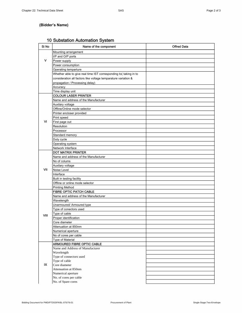
Chapter 22: Technical Data Sheet SAS Page 2 of 3
(Bidder’s Name)
10 Substation Automation System
Si No Name of the component Offred Data
Mounting arrangement
I/P and O/P ports
Power supply
Power consumption
Operating temparture
Whether able to give real time IST corresponding to( taking in to
consideration all factors like voltage temparature variation &
propagation / Processing delay)
Accuracy
Time display unit
COLOUR LASER PRINTER
Name and address of the Manufacturer
Auxilary voltage
Offline/Online mode selector
Printer encloser provided
Print speed
First page out
Resolution
Processor
Standard memory
Duty cycle
Operating system
Network Interface
DOT MATRIX PRINTER
Name and address of the Manufacturer
No of colums
Auxilary voltage
Noise Level
Interface
Built in testing facility
Offline or online mode selector
Printing Method
FIBRE OPTIC PATCH CABLE
Name and address of the Manufacturer
Wavelength
Unarmoured/ Armoured type
Type of conectors used
Type of cable
Proper identification
Core diameter
Attenuation at 850nm
Numerical aperture
No of cores per cable
Type of Material
ARMOURED FIBRE OPTIC CABLE
Name and Address of Manufacturer
Wavelength
Type of connectors used
Type of cable
Core diameter
Attenuation at 850nm
Numerical aperture
No. of cores per cable
No. of Spare cores
V
VI
VII
VIII
IX
Bidding Document for PMD/PTDSSP/KBL-075/76-01 Procurement of Plant Single-Stage:Two-Envelope
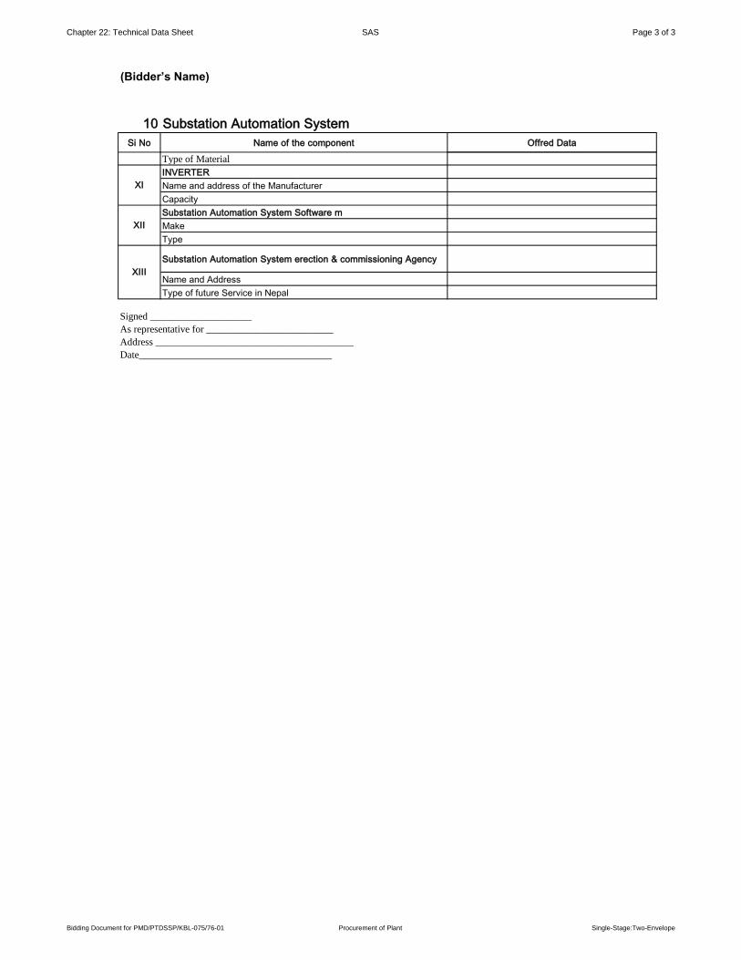
Chapter 22: Technical Data Sheet SAS Page 3 of 3
(Bidder’s Name)
10 Substation Automation System
Si No Name of the component Offred Data
Type of Material
INVERTER
Name and address of the Manufacturer
Capacity
Substation Automation System Software m
Make
Type
Substation Automation System erection & commissioning Agency
Name and Address
Type of future Service in Nepal
XII
IX
XI
XIII
Signed ____________________
As representative for _________________________
Address _______________________________________
Date______________________________________
Bidding Document for PMD/PTDSSP/KBL-075/76-01 Procurement of Plant Single-Stage:Two-Envelope
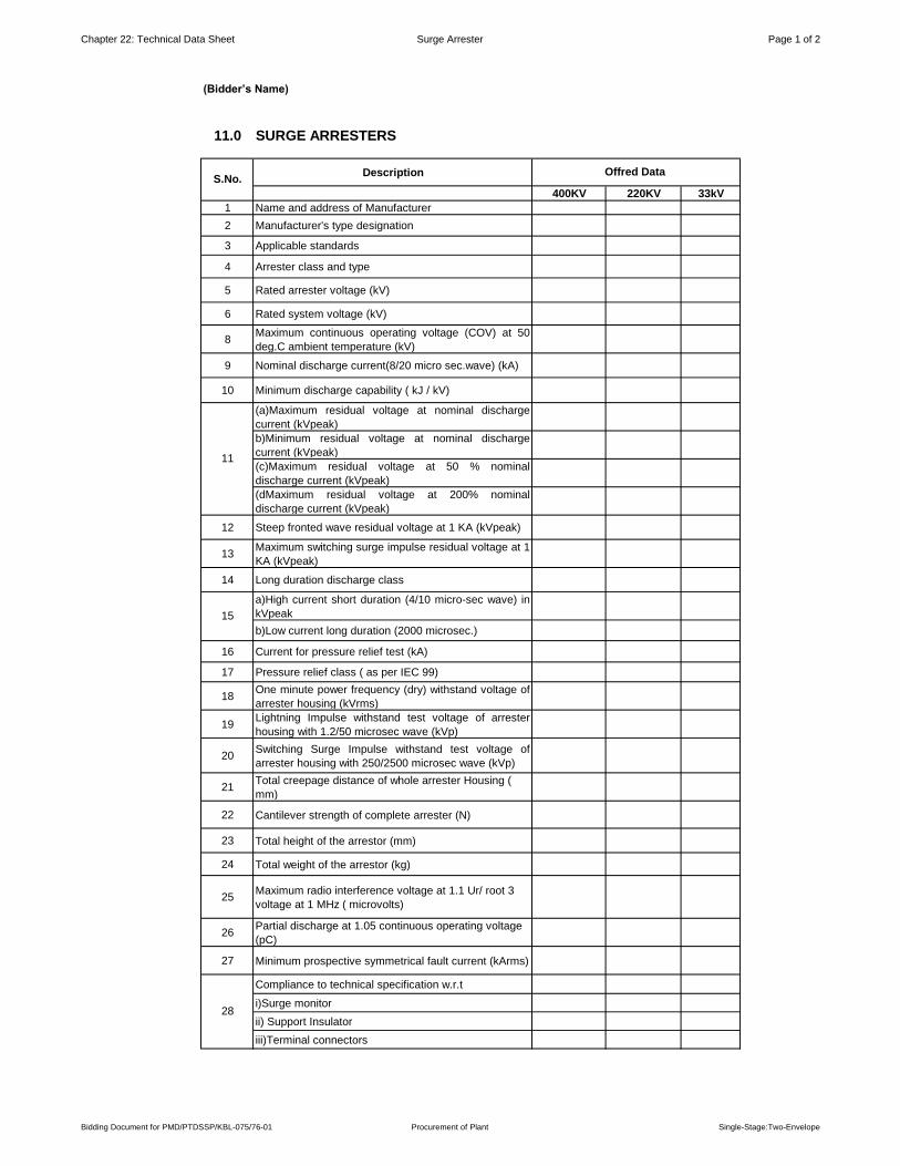
Chapter 22: Technical Data Sheet Surge Arrester Page 1 of 2
(Bidder’s Name)
11.0 SURGE ARRESTERS
Description
400KV 220KV 33kV
1 Name and address of Manufacturer
2 Manufacturer's type designation
3 Applicable standards
4 Arrester class and type
5 Rated arrester voltage (kV)
6 Rated system voltage (kV)
8Maximum continuous operating voltage (COV) at 50
deg.C ambient temperature (kV)
9 Nominal discharge current(8/20 micro sec.wave) (kA)
10 Minimum discharge capability ( kJ / kV)
(a)Maximum residual voltage at nominal discharge
current (kVpeak)
b)Minimum residual voltage at nominal discharge
current (kVpeak)
(c)Maximum residual voltage at 50 % nominal
discharge current (kVpeak)
(dMaximum residual voltage at 200% nominal
discharge current (kVpeak)
12 Steep fronted wave residual voltage at 1 KA (kVpeak)
13Maximum switching surge impulse residual voltage at 1
KA (kVpeak)
14 Long duration discharge class
a)High current short duration (4/10 micro-sec wave) in
kVpeak
b)Low current long duration (2000 microsec.)
16 Current for pressure relief test (kA)
17 Pressure relief class ( as per IEC 99)
18One minute power frequency (dry) withstand voltage of
arrester housing (kVrms)
19Lightning Impulse withstand test voltage of arrester
housing with 1.2/50 microsec wave (kVp)
20Switching Surge Impulse withstand test voltage of
arrester housing with 250/2500 microsec wave (kVp)
21Total creepage distance of whole arrester Housing (
mm)
22 Cantilever strength of complete arrester (N)
23 Total height of the arrestor (mm)
24 Total weight of the arrestor (kg)
25Maximum radio interference voltage at 1.1 Ur/ root 3
voltage at 1 MHz ( microvolts)
26Partial discharge at 1.05 continuous operating voltage
(pC)
27 Minimum prospective symmetrical fault current (kArms)
Compliance to technical specification w.r.t
i)Surge monitor
ii) Support Insulator
iii)Terminal connectors
S.No.Offred Data
11
15
28
Bidding Document for PMD/PTDSSP/KBL-075/76-01 Procurement of Plant Single-Stage:Two-Envelope

Chapter 22: Technical Data Sheet Surge Arrester Page 2 of 2
(Bidder’s Name)
11.0 SURGE ARRESTERS
Description
400KV 220KV 33kV
S.No.Offred Data
ZnO block details
a)Make and size of ZnO block
b) Whether equipment type tested
with offered type of ZnO block
30
Whether similar equipment are type tested as per IEC
or equivalent standard and are in successful operation
for at least two years.
31Overall General Arrangement drawing of Surge
arrester is to enclosed.
29
Signed ____________________
As representative for _________________________
Address _______________________________________
Date______________________________________
Bidding Document for PMD/PTDSSP/KBL-075/76-01 Procurement of Plant Single-Stage:Two-Envelope

Chapter 22: Technical Data Sheet Insulators,Hardware Accessories Page 1 of 3
(Bidder’s Name)
12.0 INSULATOR , HARDWARES & ACCESSORIES
Sl.No. Description
A. INSULATOR STRINGS 400kV 220kV 33kV
1 Manufacturer’s name and address
2 Applicable Standards
3 No. of Units per String
Weight
a) Each Disc (Kg)
b)Complete string (hardware only) (Kg)
5. Creepage Distance
a)Each Disc (mm)
b) Complete String (mm)
6. Power Frequency Withstand Voltage of the
complete string with corona control ring
i.Dry (KVrms)
ii.Wet (KVrms)
7
7. Lightning Impulse (dry) Withstand Voltage of the
Complete string for both positive and negative
peaks. (kVp)
88. Switching Surge withstand Voltage of the
Complete string with corona control (Wet) (kVp)
99. Power Frequency Puncture Withstand Voltage
(Dry & Wet) of each Disc (KV rms)
10 Page &[Page] of &[Pages]
11
11.Minimum Corona extinction (kVrms) voltage
level of the complete string with corona control ring
(Dry Condition)
12
12.RIV level of the complete (micro-volts) String
with corona control ring at 1 MHz when subjected to
a test voltage.
1313. Confirm whether string type tested with offered
disc insulator as per IEC
B. INSULATOR
1 1. Manufaturer's Name and address
2 2. Applicable Standards
3. Ultimate Strength
a) Complete assembly (kg)
b) Suspension / drop clamp (kg)
C. TUBULAR BUS CONDUCTOR
1 1.Manufacturer’s name and address
2 2.Applicable Standards
3 3.Material
Size of Tubular Bus
i.Standard pipe size- IPS (mm)
ii.Outside diameter (mm)
iii.Tolerance on outside
iv.Thickness (mm)
v.Tolerance on Thickness
5 D.C. Resistance of 20 deg.C
6 Current rating at ambient temperature of 50 deg. C
7Short circuit current rating for 1 sec. duration (kA)
Offred Data
4
5
6
3
4
Bidding Document for PMD/PTDSSP/KBL-075/76-01 Procurement of Plant Single-Stage:Two-Envelope
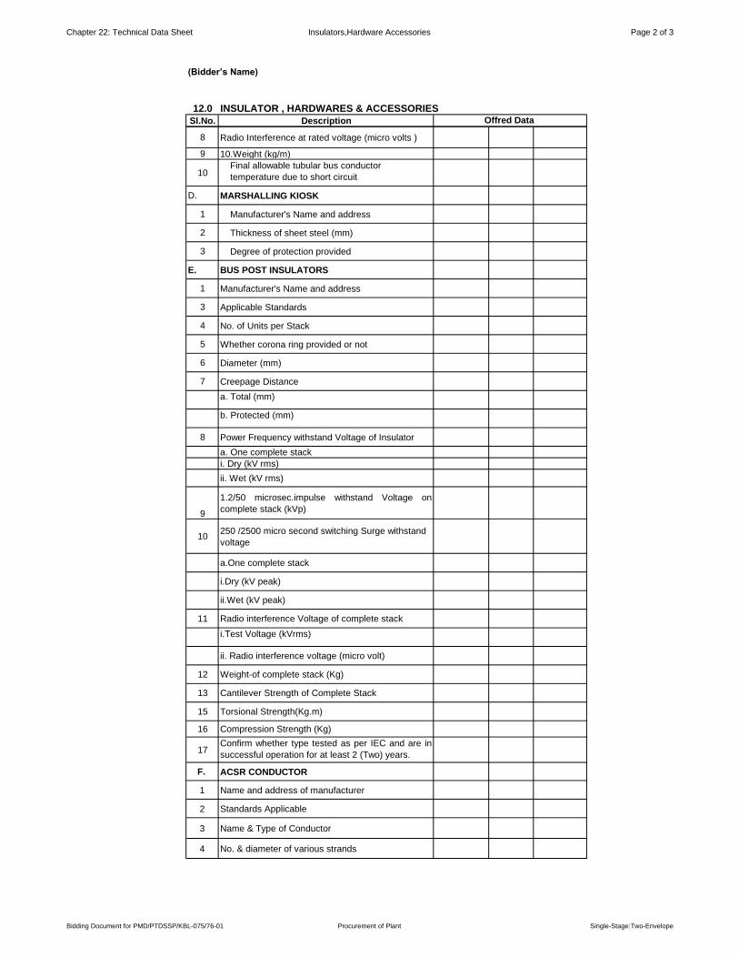
Chapter 22: Technical Data Sheet Insulators,Hardware Accessories Page 2 of 3
(Bidder’s Name)
12.0 INSULATOR , HARDWARES & ACCESSORIES
Sl.No. Description Offred Data
8 Radio Interference at rated voltage (micro volts )
9 10.Weight (kg/m)
10Final allowable tubular bus conductor
temperature due to short circuit
D. MARSHALLING KIOSK
1 Manufacturer's Name and address
2 Thickness of sheet steel (mm)
3 Degree of protection provided
E. BUS POST INSULATORS
1 Manufacturer's Name and address
3 Applicable Standards
4 No. of Units per Stack
5 Whether corona ring provided or not
6 Diameter (mm)
7 Creepage Distance
a. Total (mm)
b. Protected (mm)
8 Power Frequency withstand Voltage of Insulator
a. One complete stack
i. Dry (kV rms)
ii. Wet (kV rms)
9
1.2/50 microsec.impulse withstand Voltage on
complete stack (kVp)
10250 /2500 micro second switching Surge withstand
voltage
a.One complete stack
i.Dry (kV peak)
ii.Wet (kV peak)
11 Radio interference Voltage of complete stack
i.Test Voltage (kVrms)
ii. Radio interference voltage (micro volt)
12 Weight-of complete stack (Kg)
13 Cantilever Strength of Complete Stack
15 Torsional Strength(Kg.m)
16 Compression Strength (Kg)
17Confirm whether type tested as per IEC and are in
successful operation for at least 2 (Two) years.
F. ACSR CONDUCTOR
1 Name and address of manufacturer
2 Standards Applicable
3 Name & Type of Conductor
4 No. & diameter of various strands
Bidding Document for PMD/PTDSSP/KBL-075/76-01 Procurement of Plant Single-Stage:Two-Envelope

Chapter 22: Technical Data Sheet Insulators,Hardware Accessories Page 3 of 3
(Bidder’s Name)
12.0 INSULATOR , HARDWARES & ACCESSORIES
Sl.No. Description Offred Data
5 Overall diameter of the conductor (mm)
6Current rating capacity of the Conductor at 75 deg.
C (Amps)
7 Confirm whether type tested as per IEC
G. GALVANISED STEEL EARTHWIRE
1. Name and Address of the Manufacturer
2. Standards Applicable
3.1 UTS of the Earthwire (kN)
3.2 Lay length of outer steel layer (mm)
3.3 DC Resistance of earthwire at 20 deg. C (ohms)
3.4 Standard length of earthwire in the drum (metres)
3.5 Diameter of earthwire
Signed ____________________
As representative for _________________________
Address _______________________________________
Date______________________________________
Bidding Document for PMD/PTDSSP/KBL-075/76-01 Procurement of Plant Single-Stage:Two-Envelope

Chapter 22: Technical Data Sheet GIS Equipments Page 1 of 2
(Bidder’s Name)
13
S.N Parameters: Unit Offered Data
A
1 Nominal voltage of system kV
2 Rated voltage of system kV
3 Rated voltage for equipment (U r) kV
4Rated insulation levels phase-to-earth and between
phases
5Rated short-duration power-frequency withstand
voltage (Ud) kV
5 Rated switching impulse withstand voltage (Us)
i Phase-to-earth kV
ii Between phases kV
6 Rated lightning impulse withstand voltage (Up) kV
7 Rated frequency (fr) Hz
8 Rated normal current (Ir) A
9 Rated short-time withstand current (Ik) kA
10 Rated peak withstand current (Ip) (kA) kA11 Rated duration of short-circuit (tk) (s) S
12Rated supply voltage of closing and opening devices and
of auxiliary and control circuits (Ua) V
13Rated supply frequency of closing and opening devices
and of auxiliary circuits 50 Hz or 60 Hz
14 Neutral earthing Solidly or not solidly
15 Number of phases
16 Single- or three-phase design
17 Maximum SF6 leakage rate % / year
18 Rated filling pressure p r
Circuit-breaker
Other compartments
19 Alarm pressure p a
Circuit-breaker
Other compartments
20 Minimum functional pressure p m
Circuit-breaker
Other compartments
21 Design pressure of enclosures
Circuit-breaker
Other compartments
22 Type test pressure of enclosures
Circuit-breaker
Other compartments
23 Routine test pressure of enclosures
Circuit-breaker
Other compartments
24 Operating pressure of pressure relief device
Circuit-breaker
Other compartments
25 Internal fault
Short-circuit current kA
26 Quantity of SF6 gas of complete GIS at filling pressure Kg
27Quantity of SF6 gas of the largest compartment at filling
pressureKg
28 Maximum permissible gas dew point °C
29 Number of gas compartments
30 Length of longest section for transportation m
31Weight of the heaviest piece of equipment to be handled
during installation on-siteKg
B Bus ducts
1 Inductance H/m
2 Capacitance pF/m
GIS Equipments
Complete GIS Module
Bidding Document for PMD/PTDSSP/KBL-075/76-01 Procurement of Plant Single-Stage:Two-Envelope

Chapter 22: Technical Data Sheet GIS Equipments Page 2 of 2
(Bidder’s Name)
13
S.N Parameters: Unit Offered Data
GIS Equipments
3 Resistance of enclosure at fr Ω/m
4 Resistance of conductor at fr Ω/m
5 Surge impedance Ω
C Bushing (Outdoor-immersed bushing)
1 Type of internal insulation
2 Type of external insulation
3 Nominal specific creepage distance mm/kV
4 Shed profileNormal or
alternating
5Rated short-duration, power-frequency withstand voltage
(Ud)kV
6 Rated switching impulse withstand voltage (Us) kV
7 Rated lightning impulse withstand voltage (Up) kV
8 Cantilever test load N
9 Cantilever operation load N
10 Type of line termination
Date______________________________________
Signed ____________________
As representative for _________________________
Address _______________________________________
Bidding Document for PMD/PTDSSP/KBL-075/76-01 Procurement of Plant Single-Stage:Two-Envelope

Chapter 22: Technical Data Sheet Reactor Page 1 of 2
(Bidder’s Name)
14
S.N. Description Offered Data
1 Name of manufacturer
2 Governing Standard
3 Type of reactor
4 Type of cooling
5 Connection
6 a) Reactive power for continuous operation (MVAR)
I) At rated voltage
II) At highest voltage ( i.e. 5% higher than rated) (MVAR)
b) Rated voltage
c) Temperature rise in oil above ambient temp. ºC
d) Temperature rise of winding by resistance above ambient
temperature ºC
e) Rated frequency (Hz)
7 Number of Phases
8Guaranteed Losses at rated voltage and frequency corrected to 75
deg. C Wdg. Temp (kW)
a Load losses
b Auxiliary losses
c Total losses
9
State whether the losses are firm or Subject to tolerance. In a case
it is subject to tolerance indicate the ceiling for tolerance
(in percent)
10 Impedance :
a) Positive sequence (Ohms)
b) Zero sequence (Ohms)
11 Ratio of reactor ( i.e. Q-factor)
12Maximum remissible duration of service at 110% of rated voltage,
starting from cold without exceeding permissible temperature rise(hrs.)
13 Noise level and reference standard (db).
14 Test voltage (for winding)
a) ightning impulse (1.2/50 micro-seconds) withstand voltage (KV peak)
b) Power frequency withstand voltage (KV rms.)
c) Switching surge withstand voltage (KV peak)
15 Clearances:
a) HV phase to Phase (mm)
b) Phase to Ground (mm)
c) Neutral to Ground (mm)
16 Approximate weights (kgs.)
a. Core (kgs.)
b. Winding (kgs.)
c. Tank and fittings(kgs.)
d. Oil (kgs.)
e. Total weight (kgs.)
f. Untanking weight (kgs.) (to provide access to core and coils)
17 Quantity of oil (including 10% extra) itars.
18 Conservator
a) Total volume
b) Volume between highest and lowest visible oil levels.
19 (a) Size of largest package (mm x mm x mm)
(b) Weight of largest package (kgs.)
(c) Gross weight to be handled (kgs.)
(d) Gross volume to be handled (M3)
20 Bushing as per IS : 2099
a) Type
b) Maker's name and country of Manufacturer
c) Momentary power Frequency withstand voltage
d) One minute power frequency withstanding voltage
i) Dry (KV)
ii) Wet (KV)
e) Power Frequency puncture voltage (KV)
Shunt Reactor
Bidding Document for PMD/PTDSSP/KBL-075/76-01 Procurement of Plant Single-Stage:Two-Envelope

Chapter 22: Technical Data Sheet Reactor Page 2 of 2
(Bidder’s Name)
14
S.N. Description Offered Data
Shunt Reactor
(d) Full wave impulse withstand and voltage (KV)
(f) Impulse puncture voltage (KV)
(h) Total creepage distance in air
(i) Weight and dimensions of assembled Bushings. (KV)
21 Core
a) Type of core
b) Justification for type of core adopted
c) Technical details of the core
i) Material
ii) Thickness in mm
iii) Grade (Prime only)
iv) Insulation of core lamination
v) Press board material and thickness
22 Winding details
a) Type of winding
b) Material of the winding conductor
c) Maximum current density for windings at rated Voltage
d) Whether graded or full insulation
e) Insulating material used for winding
f) Type of axial coil supports
g) Type of radial coil supports
23 Stress on tank wall
24 Zero Sequence Reactance/ positive sequence reactance i.e. XO/XI
25 Range of voltage up to which impedance will be constant and
magnetization curve up to 2.5 pu. Voltage.
26 Vibration level
27 Amount of unbalanced current in each phase whenconnected to
symmetrical voltages.
28 Capacitance value (Phase to Ground)
29 Type of oil preservation system
30 Harmonic content in Phase current
31 Quality of oil (please enclose separate sheet for characteristics of oil)
32 Cooling calculation shall be submitted
Signed ____________________
As representative for _________________________
Address _______________________________________
Date______________________________________
Bidding Document for PMD/PTDSSP/KBL-075/76-01 Procurement of Plant Single-Stage:Two-Envelope