po07201-chamber-type-substation-design-and-construction ...
58
2021 • PO07201 • V11.1 1 CHAMBER TYPE SUBSTATION DESIGN AND CONSTRUCTION STANDARD THIS DOCUMENT IS TO DEFINE THE REQUIREMENTS, RESPONSIBILITIES AND GUIDELINES FOR THE DESIGN, CONSTRUCTION AND ACCEPTANCE OF A CHAMBER TYPE SUBSTATION. YEAR • DOC NUMBER • VERSION
-
Upload
khangminh22 -
Category
Documents
-
view
0 -
download
0
Transcript of po07201-chamber-type-substation-design-and-construction ...
2021 • PO07201 • V11.1 1
CHAMBER TYPE SUBSTATION DESIGN AND CONSTRUCTION STANDARD
THIS DOCUMENT IS TO DEFINE THE REQUIREMENTS, RESPONSIBILITIES AND GUIDELINES FOR THE DESIGN, CONSTRUCTION AND ACCEPTANCE OF A CHAMBER TYPE SUBSTATION.
YEAR • DOC NUMBER • VERSION

2021 • PO07201 • V11.1 2
CONTENTS
1. SCOPE 4
2. OBJECTIVE 4
3. GENERAL GUIDELINES 4
3.1 Chamber Substation Ownership & Maintenance Responsibilities 4
3.2 Environmental 4 3.3 Safety in Design 5 3.4 Siting and General Access 5
3.4.1 Criteria for Approval 6 3.4.2 Prohibited Locations 6 3.4.3 Prohibited Items 7 3.4.4 Fire mitigation 7 3.4.5 Vehicle Access and Parking (for
on ground and below ground chamber) 7
3.4.6 Personnel and Equipment Access 8
3.4.7 Building Below Potential Water Table 9
3.4.8 Hazards 9 3.4.9 Easements 9
3.5 Electromagnetic Fields 10 3.5.1 Background Information 10 3.5.2 Use of Electromagnetic Shielding
10 3.5.3 Design and Installation
Requirements 10 3.5.4 Applications for Approval 11 3.5.5 Evoenergy Fees and Charges 12 3.5.6 Ownership, Maintenance and
Modification of Shielding 12 3.6 Acoustic Levels 13 3.7 Drawings 13
3.7.1 Preliminary Drawings 13 3.7.2 Design Drawings 13 3.7.3 Architects Construction Drawings
13 3.7.4 Evoenergy Approval 13 3.7.5 Design Rework 14
3.7.6 Construction Drawings 14 3.8 Completion Date 14 3.9 Chamber Maintenance 15 3.10 Construction and Inspection 15 3.11 Earthing 15
3.11.1 Easement and Lease 15 3.11.2 Earth grid 15 3.11.3 Earth electrodes shall be: 16 3.11.4 Connection between Electrodes
16 3.11.5 Substation earth bar 16 3.11.6 Connection to earth grid 16 3.11.7 Equipment earthing 16 3.11.8 Structure earthing 17 3.11.9 Earth cabling inside the chamber
17 3.11.10 Connection to Different Earthing
Systems 17 3.11.11 Earth grid Inspection and Test 17
3.12 Lightning protection 18 3.13 Ventilation 18
3.13.1 General Information 18 3.13.2 Natural Ventilation 18 3.13.3 Roof Outlet Ventilators 18 3.13.4 Fire Isolation Dampers 18 3.13.5 Transformer High Temperature
Monitoring 19 3.13.6 Forced Ventilation 19
3.14 Customer Service Mains and Metering 21 3.14.1 Customer Responsibilities 21 3.14.2 Evoenergy Responsibilities 22
3.15 Fire Protection 22 3.15.1 Building Code of Australia (NCC)
22 3.15.2 Fire Extinguishers 22 3.15.3 Fire Detection 22 3.15.4 CO2 Fire Suppression System (If
Required) 23
2021 • PO07201 • V11.1 3
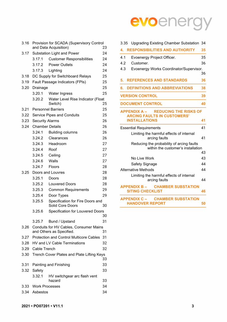
3.16 Provision for SCADA (Supervisory Control and Data Acquisition) 23
3.17 Substation Light and Power 24 3.17.1 Customer Responsibilities 24 3.17.2 Power Outlets 24 3.17.3 Lighting 24
3.18 DC Supply for Switchboard Relays 25 3.19 Fault Passage Indicators (FPIs) 25 3.20 Drainage 25
3.20.1 Water Ingress 25 3.20.2 Water Level Rise Indicator (Float
Switch) 25 3.21 Personnel Barriers 25 3.22 Service Pipes and Conduits 25 3.23 Security Alarms 26 3.24 Chamber Details 26
3.24.1 Building columns 26 3.24.2 Clearances 26 3.24.3 Headroom 27 3.24.4 Roof 27 3.24.5 Ceiling 27 3.24.6 Walls 27 3.24.7 Floors 28
3.25 Doors and Louvres 28 3.25.1 Doors 28 3.25.2 Louvered Doors 28 3.25.3 Common Requirements 29 3.25.4 Door Types 29 3.25.5 Specification for Fire Doors and
Solid Core Doors 30 3.25.6 Specification for Louvered Doors
30 3.25.7 Bund / Upstand 31
3.26 Conduits for HV Cables, Consumer Mains and Others as Specified. 31
3.27 Protection and Control Multicore Cables 31 3.28 HV and LV Cable Terminations 32 3.29 Cable Trench 32 3.30 Trench Cover Plates and Plate Lifting Keys
33 3.31 Painting and Finishing 33 3.32 Safety 33
3.32.1 HV switchgear arc flash vent hazard 33
3.33 Work Processes 34 3.34 Asbestos 34
3.35 Upgrading Existing Chamber Substation 34
4. RESPONSIBILITIES AND AUTHORITY 35
4.1 Evoenergy Project Officer. 35 4.2 Customer. 36 4.3 Evoenergy Works Coordinator/Supervisor.
36
5. REFERENCES AND STANDARDS 36
6. DEFINITIONS AND ABBREVIATIONS 38
VERSION CONTROL 39
DOCUMENT CONTROL 40
APPENDIX A – REDUCING THE RISKS OF ARCING FAULTS IN CUSTOMERS' INSTALLATIONS 41
Essential Requirements 41 Limiting the harmful effects of internal
arcing faults 41 Reducing the probability of arcing faults
within the customer’s installation 43
No Live Work 43 Safety Signage 44
Alternative Methods 44 Limiting the harmful effects of internal
arcing faults 44
APPENDIX B – CHAMBER SUBSTATION SITING CHECKLIST 46
APPENDIX C – CHAMBER SUBSTATION HANDOVER REPORT 50
2021 • PO07201 • V11.1 4
1. SCOPE
This document describes the minimum design and construction requirements for all new chamber substations in Evoenergy’s distribution network. These requirements may also apply to upgrade or modification works to existing chamber substations.
This guideline is applicable to the design and construction of ‘On Ground’ and ‘Below Ground’ substation chambers. Any variation to this guideline must be negotiated and approved by Evoenergy’s project officer; otherwise the requirements of this guideline shall be strictly adhered to.
All ‘indoor substations’ below the footpath or roadway level, where access is gained, shall, for the purposes of this guideline, be treated as ‘Below Ground Chamber’ substations.
In the case of a building containing multi-level basements, subject to the above clause, the ‘Below Ground Chamber’ substation must be at the first usable level below constructed final ground level.
In all cases, the chamber floor level of a ‘Below Ground Chamber’ substation is not to exceed 4.3 metres below ground level of the adjacent finished level of the footpath or roadway from where equipment access is gained.
2. OBJECTIVE
The purpose of this document is to define the requirements, responsibilities and guidelines for the design, construction and acceptance of a Chamber type substation.
Note: Padmount Substations are the preferred solution and should be implemented where possible. Where there are no technically viable alternatives, a Chamber substation may be permitted only with the written approval of Evoenergy prior to the commencement of the design.
3. GENERAL GUIDELINES
3.1 Chamber Substation Ownership & Maintenance Responsibilities The standard ownership arrangement is that:
Evoenergy owns the electrical distribution equipment in the substation chamber, and controls the access to the chamber substation.
The Building owner owns and maintains the structure and auxiliary services of the substation chamber, which are basically the walls, floor, ceiling/roof, doors, lighting, security systems, fire monitoring & control equipment, and pumping and ventilation equipment (which may not necessarily be located inside the chamber substation).
The substation target design life of 50 years sets particular requirements for the careful selection of materials and equipment and for high standards of workmanship.
Maintenance periods for the electrical distribution equipment are specified in the relevant Technical Maintenance Plan.
The Service Provider’s quality of work and materials supplied must be adequate for the substation to meet or exceed its design life and maintenance performance requirements.
Where there is a different ownership arrangement proposed, individual agreements will be made defining the arrangements, including who is accountable for the safety of personnel and for the security of supply.
3.2 Environmental Relevant Project / Planning / Asset Engineer or Officer must contact the Environmental Officer to access the site for cultural sensitivity, significant trees, threatened species, asbestos dumping grounds, polluted sites etc. Environmental Protection Management Plan (EPMP) should be in place with DA approval before the

2021 • PO07201 • V11.1 5
start of work. EPMP may not be required for small development and the Environmental Officer should be consulted in such cases before the start of work.
Some sites may require an Environmental Impact Statement (EIS) which details the anticipated environmental impacts of a development on the environment as well as proposing avoidance, mitigation and offset measures. An EIS is prepared by a proponent to enable decision makers to understand the environmental consequences of a proposed development.
3.3 Safety in Design Designs must allow for optimal utilisation of readily available plant materials and equipment as well as standard work practices routinely employed in construction and maintenance activities including the application of live-line working procedures where appropriate. Design also must consider the fire risk of locating assets in the vicinity of a building.
Designs must allow for and adhere to the standard safety work practices routinely employed in the construction and maintenance activities within Evoenergy. Designs must comply with the Utilities Act and its supporting documentation and the Safe Design of Structures Code of Practice under the ACT Work Health Safety Act 2011 and Evoenergy’s corporate risk management procedures. For further detail refer to Evoenergy document PO0785 “Capital Works Design Checklist Procedure”.
3.4 Siting and General Access Compliance with the following conditions is necessary to gain approval to receive supply from Evoenergy:
The substation chamber equipment entry shall be at ground level to allow easy access for heavy vehicles to the equipment entrance at all times.
Evoenergy personnel must have 24 hour access seven days a week, through dedicated access ways which must be at least 1200 mm wide. Doorways must be 1000mm wide when the door is in the open position.
No public or occupant access must be through the Evoenergy dedicated access ways. This includes periods of emergency evacuation when Evoenergy or firefighting personnel may require unhindered access into the Chamber Substation and associated access ways.
There must not be any requirement to move any material or traverse around any item or persons in or at the entry/exit points of the access ways.
All access ways must be located to ensure egress and ingress from or onto a public street or an all-weather heavy-duty access roadway which complies with the BCA egress and ingress requirements.
The substation chamber must be located:
In an area free of other building services other than those directly relating to the substation. This includes any ground beneath the substation.
On a stable and clear area free of any obstruction which could interfere with the installation of any part of the earthing system.
Evoenergy personnel shall have free access at all times to the chamber via the equipment hatch (doors) and personnel access doors. Provision of a permanent all-weather access route is required and access through security areas where guard dogs or similar may be used is not acceptable. An acceptable gate access arrangement is a locking bar or chain with provision for an Evoenergy lock and a customer lock in series. For further details refer to clause 3.21 regarding security alarms.
The area in the immediate vicinity of each access door shall be designed in such a manner to prevent outward opening access doors and passageways being obstructed by stores, equipment, vehicles and litter etc.
The substation floor shall be above the 100-year flood level.
The substation chamber, including escape routes, are to lead outside the ‘secure perimeter’ of the building (secure perimeter can include the chamber internal walls, floor and ceiling where these are within the building).
2021 • PO07201 • V11.1 6
3.4.1 Criteria for Approval
The following items, as a minimum, must be taken into account when assessing a site or location for establishment of a Chamber Substation:
The substation, the required access ways, conduit routes, ventilation ducts and cable risers as appropriate must in general be provided in accordance with Evoenergy’s standard easement requirements or easement memorandum.
The substation, the required access ways, conduit routes, ventilation ducts and cable risers as appropriate must be located in areas which are free of any other building, structure or services excluding services or conduits directly related, required and approved by Evoenergy for the chamber substation.
The selected site is required to be geotechnically stable and certified by a geotechnical engineer as safe for the intended loadings by the substation building, substation equipment and any underground conduits servicing the substation.
The structure of the substation or chamber must be certified, as being designed to Australian Standards which provides a 50 year life cycle, by a practicing structural engineer prior to Evoenergy approval or supply being made available to the substation.
The selected site/location shall be clear of all obstructions which may interfere with the installation of any part of the substation earthing system.
Note: Electrodes from the earthing system may extend several metres into the ground.
Any services including, but not limited to, stormwater or subsoil drains, sewers, gas, water, fire services, air-conditioning installations, electrical or communications cables, conduits or pipe work other than those specified by Evoenergy, must not pass through or encroach into the substation site area or its required or associated access, services passageways, ventilation duct or cable riser clearances.
Columns, beams, footings or any part of any other building or structure shall not encroach on the clearances referred to in this guideline, within any portion of the substation or associated access or services passageways area or any space required for ventilation ducts.
3.4.2 Prohibited Locations
Access ways must not be located in areas where access may be obstructed by persons, vehicles, equipment, material storage areas, site usage, enclosed or partially enclosed car parks, loading docks, similar facilities or any other possible impediments.
Access to Chamber Substations must not involve or permit access into or through other parts of the building. Arrangements where substation egress or access is into or through enclosed or courtyard locations other than those dedicated to the substation are prohibited. No access ways must be by or involve access through areas which may be deemed to be dangerous to personnel. This includes, but is not limited to, access through areas patrolled by guard dogs or operations involving vehicles, machinery or equipment.
The following locations are not acceptable:
Where the ambient air temperature is above 400C (or daily average exceeds 350C)
Where the average humidity over a day exceeds 95%, measured over a period of 24Hrs
Where the ambient air has high levels of dust, smoke, combustible or corrosive pollutants
Where there is concern over vibration due to causes external to the substation equipment

2021 • PO07201 • V11.1 7
Where it is likely to contain any portion of another building or structure other than the building in which the substation is housed which is within 3 metres in any direction from the ventilation openings of the chamber substation.
Altitude exceeds 1000m above sea level
3.4.3 Prohibited Items
Except for services, facilities or installations directly associated with the substation; no other services, facilities or installations are permitted within a dedicated access way.
Consumer’s mains, switchboards, metering or any other parts of the consumer’s installation are not permitted in a dedicated access way for a substation.
No materials, equipment or other objects are to be stored or placed within an access way.
3.4.4 Fire mitigation
Electrical apparatus typically installed in chamber substations are considered fire source features as defined in the National Construction Code (NCC). The placement of the substation must be proposed considering the fire resistance of nearby structures. Consideration to structures on the burdened land and adjacent parcels must be considered.
Fire resistance levels must satisfy requirements listed in the National Construction Code and AS2067 Substations and High Voltage Installations.
3.4.4.1 Compliance with the national construction code
The proposing party must ensure the proposed substation is in compliance with the NCC. Adequate fire resistance levels to the building and those nearby the proposed location must be achieved. The proposed location of the substation must not render existing or proposed nearby structures non-compliant to the National Construction Code (NCC).
The substation must be segregated from the remainder of the building which it is constructed in accordance with the NCC. Electrical substations must effectively be constructed in a dedicated fire compartment. External surfaces to the building surrounding any non-fire rated openings (including louvered doors) must have adequate fire resistance levels specified.
Evoenergy is in reliance of information and noted compliance provided by the proposing party in relation to compliance to the NCC requirements.
3.4.4.2 Compliance to AS2067
In addition to comply with the NCC substation locations must comply with the requirements outlined in AS2067 (Substations and high voltage installations).
For the purposes of compliance to AS2067 all transformers that are 1kVA or greater are considered to have an oil liquid volume of greater than 1000L.
3.4.4.3 Blast Rating
A minimum blast rating of 2kPa must be achieved for all structural components and dividing walls that segregate the chamber substation from the remainder of the building. Where the chamber substation is accessed through a corridor, the corridor must have the same blast rating and fire resistance levels to all surfaces that are specified in the chamber substation room.
All components of a fire rated access corridor must be constructed from reinforced concrete or reinforced block work. All substation chambers and access way walls are to be structurally tied at the floor and the ceiling. Internal doors are to be fire rated to NCC and AS 2067. All fire rated doors are to be supplied certified and tagged with the fire rating.
3.4.5 Vehicle Access and Parking (for on ground and below ground chamber)
The area or driveway to the substation chamber shall be a minimum 3 metres wide. This area shall be suitable to bear the combined weight of a vehicle plus payload of 26 tonnes (gross vehicle mass), with a maximum

2021 • PO07201 • V11.1 8
axle load of 18 tonnes for semi-trailer truck. The access route slope must not exceed 1:12. In addition to vehicle access, there should be enough area available for turning of semi-trailer trucks.
The access must have a minimum headroom of 5.5 metres for the entire route and the area outside the chamber substation equipment entrance shall have a minimum clear height of 6 metres to allow for the operation of a heavy crane.
A 2.5metre wide loading area along the full length of the wall containing the equipment access doors, which is not located in a driveway requiring traffic management, shall be provided. The level of this loading area immediately outside the substation shall be at the same level as the substation floor with a 1:100 fall away from the substation.
24 hour parking for Operational Personnel shall be available in the immediate vicinity of the substation and the substation access doors shall be fitted with signs approved by the relevant authority, which indicate ‘No Parking. 24 hour access required’.
While under construction Evoenergy vehicles must be allowed to park at the substation for construction purposes.
While Evoenergy will take all reasonable measures and care to avoid damage to the building, civil or road works during the movement and installation of substation equipment it is the responsibility of the developer or property owner to make good any such damage were it to occur.
3.4.6 Personnel and Equipment Access
Unimpeded and unrestricted access, without notice, by Evoenergy personnel to all Evoenergy substations must be maintained 24 hours, 7 days a week. This requirement must be included in any immediate or future building security arrangements. The imposing of restrictions to substation personnel access such as the obtaining of approval or arranging access through the building owner, tenant, building security (‘off or on site’) or other source is not acceptable.
Reference is made to the Utilities Act 2000 which provides for 24 hours access to the premises by authorised Evoenergy persons to carry out activities necessary for the operation of the distribution network.
Substations must be provided with direct street access or be accessible using permanent all weather routes. Access points must be located where they will not be obstructed by vehicles, equipment, and site usage or any other impediments. Access through areas that are deemed dangerous to personnel, such as areas patrolled by guard dogs is unacceptable. Access routes (including corridors where applicable) must have a fire rating equivalent to that of the rest of the substation. Entry into any substation by unauthorised personnel is not allowed. External doors and gates must be fitted with suitable key operated locks as approved by Evoenergy.
Personnel and equipment access hatchways are not permitted. Normal personnel entry to the substation chamber is to be effected through personnel entry doors only.
Below Ground substations with personnel access via staircases require the stairways to be fitted with handrails and to have a minimum clear width of 1200mm between the handrails. Minimum stairway headroom is 2200mm.
Personnel access doors are to be used for normal entry and exit from the substation. All substations must be provided with two separate personnel access doors. The second personnel door may not be required if an equipment access door is suitably located in one of the walls with provision for personnel access, at the discretion of Evoenergy.
Personnel access doors are also used to facilitate rapid escape in the event of fire or explosion. For this reason, personnel access doors should be located diagonally opposite where possible.
Doors for personnel and equipment access shall provide the following:
Unobstructed access clear of the building.
Access to a public area (roadway, footpath etc.).
Be situated as close to the front property boundary as possible.

2021 • PO07201 • V11.1 9
Personnel access doors are not to open directly onto a driveway/roadway unless bollards have been installed to prevent vehicles passing or parking within 1.2m of the access doors
3.4.7 Building Below Potential Water Table
In situations where the substation (or any associated chamber, pit or conduit) is below the level to which the surrounding water table may rise under any condition, both the wall cavity and the under floor area of the substation and associated chamber must be gravity drained to a suitable discharge point or to a collection tank.
In some instances, an oil separation tank may also be required. The tanks must be external to the substation and have a reliable automatic discharge pumping system.
The pumping system must be installed to the appropriate Australian Standard and the wiring and control system is to be supplied from the building essential services. An appropriate label is to be fixed to a substation wall indicating the presence of the pumping system and the source of the power to the pump. The water must be pumped into the sewerage system, and not the stormwater system. An appropriately designed system certified by a practising Civil or Hydraulic Engineer may be considered by Evoenergy to satisfy this requirement. The need to automate the starting of the pump is to be discussed and agreed with Evoenergy on a case-by-case basis.
All drainage discharge must be external to the ‘Below Ground Chamber’ substation and have a reliable automatic discharge pumping system. The pumping system must be installed to the appropriate Australian Standard and the wiring and control system is to be independent of the substation. Service and maintenance of the pumping equipment is the responsibility of the building owner. To comply with this section, two pumps must be provided to ensure back up in the event of failure of the first pump.
The substation floor must be designed to withstand any hydrostatic pressure to which it may be subject if the pumping system may fail. Particular attention must be paid to the incorporation of waterproofing membranes and the sealing of cable entries. If at any stage in the life of the substation chamber it is found that flooding is occurring, the building owner will have to supply and fit water stopping features deemed necessary by Evoenergy. The owner is responsible for the repair of any leaks into the chamber.
3.4.8 Hazards
Substations contain high voltage and low voltage apparatus and cables, oil, gas insulated equipment, plastics, concrete and other materials. In some situations, a substation may be regarded as a hazardous source or be exposed to hazardous sources.
Therefore, the substation chamber and access to it shall not be located in a hazardous area as classified in AS/NZS 3000: Electrical installations (known as the Australian/New Zealand Wiring Rules). There shall be no piping or storage of hazardous materials or volatile liquids in the vicinity of the substation. Conformance with AS 2430.3 series – ‘Classification of Hazardous Areas’ and AS2381 ‘Electrical Equipment for Explosive Atmospheres-Selection, Installation and Maintenance’ is mandatory. Special attention shall be paid to personnel access, escape routes and ventilation openings ensuring that they do not face onto or open into a hazardous area.
Evoenergy is in reliance of information and noted compliance provided by the proposing party in relation to compliance to AS/NZS 3000 requirements in regards to hazardous location.
Substations may contain hazardous levels of SF6 gas accumulated at the lowest point in the substation. All personnel entering a confined space within the substation (e.g., trenches) shall ensure safe oxygen levels with the use of a gas detection device.
3.4.9 Easements
An easement in gross may be required to protect the route of cabling and other substation service elements (such as external ductwork pipework) from subsequent on-site development activity. Easements are also required for cable routes that pass through another property before reaching a public thoroughfare and for the substation earthing system. For further details see clause 3.9.1 in regards to electrodes, earth grid and earth conductor routes back to the substation.

2021 • PO07201 • V11.1 10
3.5 Electromagnetic Fields
3.5.1 Background Information
Power cables, transformers and other current carrying equipment in a substation are typical sources of electromagnetic fields.
Further, electromagnetic fields can have undesirable effects on susceptible equipment (e.g. computer monitors, medical equipment). This should be considered when choosing a substation location and when siting such sensitive equipment in the vicinity of a chamber substation. The substation, for example, shall not be located adjacent to, above, or below operating theatres or similar areas where sensitive instrumentation is to be installed (refer also to AS 3003).
In accordance with the above, Evoenergy Network’s standard indoor chamber substation equipment layouts are typically designed to minimise electromagnetic radiation from within the substation. The key features of these layouts are:
Low voltage switchboard and transformer located adjacent to each other and as close as practical to minimise the length of the low voltage transformer tails.
Heavy current low voltage conductors located in trenches, away from walls and ceilings, and by bundling conductors where possible, i.e. by laying A, B and C phases and neutral together as a group rather than in different ducts or in flat formation.
Where alternative layouts are proposed, the impact on electromagnetic radiation from the substation should be considered. In such circumstances, special attention should be given to heavily loaded consumer mains, and especially, loads with high third harmonic content (or multiples of the third harmonic), which increase the difficulty of minimising EMF.
3.5.2 Use of Electromagnetic Shielding
Evoenergy, consistent with electricity distribution industry policies, recommends prudent avoidance of exposure to electromagnetic fields. Accordingly, Evoenergy recommends against the positioning of inhabited spaces, such as residential units and commercial offices, immediately adjacent or above indoor chamber substations where the occupants may be exposed to electromagnetic fields for extended periods.
In addition, Evoenergy Network’s standard indoor chamber substation equipment layouts are typically designed to minimise electromagnetic radiation from within the substation. The key features of these layouts are detailed below and where alternate layouts are proposed, the impact on electromagnetic radiation from the substation should be considered:
1. Low voltage switchboard and transformer located adjacent to each other and as close as practical to minimise the length of the low voltage transformer tails.
2. Low voltage consumer mains entry into the substation via cable trenches in the substation floor in lieu of overhead cable entry.
Evoenergy Networks DOES NOT install or require installation of electromagnetic shielding within indoor chamber substations.
A customer / developer may, however, apply for approval to install electromagnetic shielding within an Evoenergy Electricity Networks indoor chamber substation.
Evoenergy Networks strongly recommends that the requirement for shielding be considered at the initial concept stage of the development/facility as design and approval of the shielding can be considered under the normal substation chamber approval process.
Installation of any proposed shielding will also typically be easier and at lower cost if undertaken prior to hand-over of the substation chamber to Evoenergy Networks.
3.5.3 Design and Installation Requirements
The design of any proposed electromagnetic shielding should consider the ultimate potential electromagnetic field strengths that may be generated from within the substation and the corresponding required level of attenuation to be achieved outside the chamber.
2021 • PO07201 • V11.1 11
The shielding material shall be selected accordingly with appropriate consideration of the support and fixing methods. The shielding design shall also consider and accommodate expansion and contraction of the shielding material due to temperature variations.
All electromagnetic shielding installed within an Evoenergy Networks indoor chamber substation shall comply with the following requirements:
Electromagnetic shielding shall be:
Constructed entirely of non-flammable materials
Designed and installed to avoid creation of condensation within the substation and prevent condensate from dripping onto equipment within the substation
Designed and installed such that it will not require routine maintenance during the life of the installation; i.e., the shielding shall be maintenance free.
Of solid construction and be securely mounted/fixed in place with approved fixing methods
Solidly earthed to the substation earth at a location approved by Evoenergy
Painted white or otherwise finished in a light colour to ensure maximum light reflection
Electromagnetic shielding shall not:
Impede personnel access to and egress from the substation
Impede access to substation equipment and/or fittings
Impede operation of substation equipment and/or fittings
Impede maintenance of substation equipment and/or fittings
Impede equipment access to and removal from the substation
Impede or obscure general lighting (including lighting levels), emergency lights or exit lights within the substation
Impede ventilation of, or airflow within, the substation
Impede or obscure signage within the substation
Compromise the design fire resistance level of the chamber walls
Evoenergy will not be constrained in the design, operation, and loading of a substation containing shielding when upgrading that substation to accommodate an increased electrical load irrespective of the cause of the increased load.
Evoenergy Networks will not be obliged to modify the design or internal arrangements of equipment and/or connections within the substation chamber to reduce the strength of the electromagnetic fields generated from within the substation.
Evoenergy accepts no responsibility for the initial or ongoing performance and operational effectiveness of the shielding design or installation. This shall be the responsibility of the shielding designer and/or building owner.
Evoenergy can provide, on application, measurements of electromagnetic and electric fields prior to and after installation of the shielding together with corresponding electrical load data at the time of measurement. Charges will apply for this service
Evoenergy can also provide, on application, an indication of the ultimate configuration and corresponding electrical load in accordance with the current Evoenergy Networks policies, standards, and equipment.
3.5.4 Applications for Approval
Where a customer / developer proposes installation of electromagnetic shielding within a new chamber substation, a written request is to be made to the relevant project officer. However, if the request is for an existing chamber substation with Evoenergy Network where the project officer is not allocated, a minor works

2021 • PO07201 • V11.1 12
application must be lodged with Customer Technical Services Manager over the email: [email protected].
The request / application shall be sufficiently detailed to allow thorough assessment of the shielding proposal in accordance with the section ‘Design and Installation Requirements’ (above) and shall include, as a minimum, general arrangement and detailed construction plans. As a minimum, such plans shall clearly show the following:
Area / extent of proposed shielding
Type of proposed shielding
Method of mounting of the proposed shielding
Earthing details including location and connection details and methods
Where shielding is proposed to be installed prior to hand-over of the substation to Evoenergy Networks, the customer / developer need not make a separate application to Evoenergy Networks if the proposed shielding is fully detailed on the substation construction drawings that are to be submitted for substation chamber approval prior to construction.
In such instances Evoenergy may require that the proposed shielding accommodate Evoenergy fixtures and/or fittings that will be required to be installed during the substation fit-out. Alternatively, Evoenergy may require that the developer/building owner include such provisions in the chamber construction for subsequent hand-over to Evoenergy Networks.
Evoenergy’s approval of a shielding proposal provides only Evoenergy’s consent to proceed with the works. Evoenergy does not warrant, in any way, the technical performance of the shielding installation to achieve the designed / intended attenuation.
3.5.5 Evoenergy Fees and Charges
All works required to install, maintain and/or modify shielding within an Evoenergy Networks indoor chamber substation shall be the responsibility of the customer / developer.
All costs associated with the installation of shielding within an Evoenergy Networks indoor chamber substation including all applicable Evoenergy fees and charges shall be borne by the customer / developer.
Evoenergy fees and charges will generally apply for installation of shielding within a substation after it has already been handed-over to Evoenergy Networks and will typically be applicable to the following activities:
Review and approval of shielding proposals,
Provision of access to the substation and supervision of contractors working within the substation,
Provision of network switching and isolation of the substation or parts of the substation including the issuing of appropriate work permits and restoring the network and substation to normal configuration and operation,
Site inspection and verification of the completed shielding installation,
The final physical connection of the shielding to the substation earth mat, and
Measurement of electromagnetic field strengths and corresponding electrical loads before and/or after installation of shielding.
All such fees and charges are payable prior to any works commencing. A formal Evoenergy Networks quotation detailing the required activities will be provided on application.
3.5.6 Ownership, Maintenance and Modification of Shielding
Shielding installed within an indoor chamber substation will be considered to be part of the substation chamber structure. Accordingly, the building owner shall own and be responsible for the maintenance of electromagnetic shielding during the life of the substation.
Where Evoenergy identifies a defect with shielding installed within an indoor chamber substation, a written notification will be issued to the building owner/manager requesting rectification in a timely manner. In instances where the defect presents an immediate safety or network performance risk Evoenergy may take

2021 • PO07201 • V11.1 13
immediate measures to address this. The cost for this rectification exercise as well as for any works to reinstate the shielding will be borne by the building owner.
Evoenergy fees and charges will be payable in accordance with the clause 3.3.5 (above) should access to the substation or contractor supervision whilst within the substation or network / substation switching and isolation be required for the maintenance works.
Pursuant to the initial installation of shielding the building owner/manager acknowledges and accepts that changes to the substation chamber (for example to accommodate an additional transformer) may result in a requirement to modify or extend the shielding. The building owner/manager further acknowledges that adjacent inhabitants may experience a higher exposure level as a result of such activities until such time as the shielding modifications and/or extensions are completed and/or reinstated.
3.6 Acoustic Levels The ambient noise level shall be as low as reasonably practicable and not more than 85dB (A) for working in the substation. External noise level due to substation operation shall be as low as reasonably practicable. Refer to ACT Environment Protection Regulation 2005.
3.7 Drawings All indoor chambers must have the relevant design and siting approvals from relevant authorities before construction can commence. Evoenergy will not proceed with the review of the internal substation chamber design until evidence has been provided of such approvals.
3.7.1 Preliminary Drawings
To enable Evoenergy to carry out a preliminary design of the substation chamber the architect shall provide Evoenergy with the following drawings and information in electronic media at the initial consultation:
A site plan to scale showing the proposed location of chamber and of customer’s switch room
A detailed 1:50 scale plan of the proposed chamber
Detailed plans of access routes to the chamber
Details of all electrical load requirements (Maximum Demand to AS3000).
Gross floor area of the building.
3.7.2 Design Drawings
For Evoenergy to proceed with the review of the substation chamber and earth grid design, the architect shall provide a site plan to scale including the location and details of the chamber and customer’s main switch room in AutoCAD format (electronically).
Evoenergy will return the design drawings in AutoCAD format (electronically) to the architect showing any changes required to the layout of the substation, the construction details, and earthing requirements which are to be incorporated in the architect’s construction drawings.
3.7.3 Architects Construction Drawings
The architect’s construction drawings of the substation chamber shall be forwarded to Evoenergy for final review.
The drawings shall show in detail the location of the substation, all construction features as required by Evoenergy, drainage details of the areas adjacent to the chamber exterior, and routes and profile drawings of cable entry conduits.
Drawings shall be provided in digital format, developer must contact relevant Evoenergy Project Officer for requirements.
3.7.4 Evoenergy Approval
When the substation design has been approved by Evoenergy a copy of the approved drawing will be forwarded to the architect.

2021 • PO07201 • V11.1 14
3.7.5 Design Rework
Evoenergy may require a design rework fee for any excess design work requested due to changes after the approved design.
3.7.6 Construction Drawings
To enable Evoenergy field staff to carry out an installation, testing and commissioning of chamber substation equipment and switchboards within the substation chamber, the relevant project/design engineer shall prepare and issue the drawings listed in table 1 as “Issued for Construction” as part of handover of construction documentation for new and existing chamber substation (if any upgrade is required).
TABLE 1. LIST OF CONSTRUCTION DRAWINGS
DRAWING TITLE Drawing Number Desired Information Single Line Diagram 42xxx – yyyyy - 00 Location and interconnections of high and
low voltage equipment and conductors, with equipment identification as per PO 0735 and incoming & outgoing cable details with source/destination descriptions
Substation Construction Requirement
42xxx – yyyyy - 10 In line with typical substation layout requirement drawings adjusted to actual project site, showing the electrical equipment, earthing arrangement, clearances and separations in compliance against 3.24.2.
Substation Fit-out 42xxx – yyyyy - 20 Detailed scope of work for Evoenergy and Developer/Customer/Customers Electrical Contractor including the legends.
AC Schematic Sequential and start with 42xxx – yyyyy – 30 (refer note)
AC System Wiring Details DC Schematic DC System Wiring Details Tx HV Switchgear Wiring Diagram
Protection and Control Wiring Termination Details
LV Switchgear wiring diagram
Protection and Control Wiring Termination Details
Tx Thermometer wiring diagram
Thermometer wiring details
SCADA cubicle panel arrangement
SCADA cubical panel arrangement with showing relevant clearance from other equipment
SCADA cubicle wiring diagram
SCADA system diagrams and termination details
Multicore schedule RTU Panel cable schedule
Note :xxx (3 digits): Suburb number allocated through meridian and yyyyy (5 digits): Substation number
3.8 Completion Date The time required by Evoenergy to install and commission the electrical equipment is twelve (12) working weeks from the date the substation enclosure is accepted by Evoenergy, conditional on Evoenergy being provided with free and unobstructed vehicular access to the enclosure for the delivery of electrical equipment from the time of acceptance.
It should be noted that this does not constitute a guarantee of supply within that time. Evoenergy reserves the right to commission the electrical equipment nearer to the date that the customer requires electricity supply.
2021 • PO07201 • V11.1 15
Evoenergy is not bound to the above time when specialised equipment with an extra-long lead time is required.
Prior to electrical supply being made available, a Certificate of Electrical Safety (CES) shall be submitted to the ACT Government and three sets of ‘As Built’ drawings are to be supplied to Evoenergy for final checking.
Main switchboards will only be energised from the substation after:
The Certificate of Electrical Safety has been submitted and an ACT Government has inspected and affixed an approved sticker to the front of the main switchboard.
The final customer has arranged an Electricity Account with an Electricity Retailer and their metering has been installed.
A “Request for Service” (RFS) has been forwarded to Evoenergy.
The ‘As Built’ drawings have been supplied.
3.9 Chamber Maintenance The structural and external maintenance of the substation chamber remains the responsibility of the building owner, refer to Clause 3.2 and 3.2.8 “Building below a Potential Water Table” regarding any water ingress.
3.10 Construction and Inspection Evoenergy shall be advised of the construction program to allow personnel to visit the site from time to time to inspect the construction stages of the chamber as follows:
Earth grid inspection and test as per clause 3.9 below.
Conduit and cable duct layout, prior to the concrete floor being poured.
Completion of the substation chamber, prior to take over. At this stage the Evoenergy Project Officer shall ensure that the chamber conforms to Evoenergy requirements by completing the Handover Inspection Report as per Appendix C.
Evoenergy must be notified five working days in advance of an inspection being required.
3.11 Earthing
3.11.1 Easement and Lease
The easement or areas required for earth cables from the earthing electrode installation to the Chamber Substation and the earthing electrode installation area, are to be included in the lease and easement documentation for the Chamber Substation.
A buried earth grid is required for the substation and shall be installed in unexcavated or suitable filled and consolidated ground. It shall be located under an area that will be concreted and installed before the concrete is poured or laid. The footprint of the chamber shall be located within the perimeter of the earth grid.
3.11.2 Earth grid
The earth grid is to be designed and constructed in accordance with the guidelines provided in Evoenergy’s ‘Distribution Earthing Design and Construction Manual - SM1138’. As noted in SM1138 the design shall implement the standards and guidelines of AS/NZS7000 and AS/NZS 2067.
The contractor shall carry out soil resistivity tests at the substation site and use these readings to design an earth grid. Design computations shall be submitted to Evoenergy for checking, prior to installation by the appropriate (sub) contractor.
NOTE The results of the resistivity test will depend on the condition of the soil at the time of testing. As soil resistivity is influenced by seasonal and prevailing weather conditions, design and final test results can be inconsistent due to the time delay between initial resistivity testing and final earth grid testing. The designer shall take this

2021 • PO07201 • V11.1 16
into account when designing the earth grid to ensure calculated values show a reasonable alignment with measured values.
The earth grid will consist of vertically driven or drilled electrodes interconnected as detailed on drawing 4961-01 ‘Standard Earth Grid Electrode Connection Details for Chamber Substations’
If the substation is located on natural ground, the earthing system is to be installed directly under the floor slab. However, if the substation is constructed on a suspended floor slab, the earthing system is to be installed at the lowest level of building excavation directly below the substation footprint.
All items including rods, conductors and connectors shall be clean, free of burrs, cracks and sharp edges.
The earthing system must be protected from damage during construction. Failure to do so will require damage to be repaired to the satisfaction of Evoenergy.
3.11.3 Earth electrodes shall be:
Of the driven type using 15mm minimum diameter copper clad steel earth rods incorporating a protective driving point and head cap, or
25mm x 3mm copper strip, 15mm diameter minimum copper clad steel earth rods or nominal 70mm2 minimum stranded bare copper conductor inserted into 50mm diameter holes drilled to the required depth. Drilled holes must be filled with an Earthing Enhancement Compound as per AS 2239-2003: “Galvanic (sacrificial) anodes for Cathodic Protection”, section 4 and in accordance with above mentioned drawing 4961-01.
The earthing electrode system including electrode and equipotential bonding interconnections are to be installed before any waterproof membranes are laid and before the covering floor slab is constructed. Earth electrodes are to be installed at no less than their vertical length apart and they must be connected using a cable type earth grid. Cable identification markers are to be installed in the finished surface over the earth grid cable.
3.11.4 Connection between Electrodes
Connections between electrodes shall be made by 25mm x 3mm copper strap or nominal 70mm2 stranded bare copper conductors exothermically welded or brazed in accordance with above mentioned drawing 4961-01. All connections shall be buried to a minimum depth of 500mm where they are outside the footprint of the building or substation chamber.
3.11.5 Substation earth bar
An earth bar shall be installed approximately 300mm above the substation floor at the end of the HV trench. Refer to Drawing 4961-03 for earth bar construction and location details. Cable connections to the substation earth bar shall be made with bolts, washers and nuts of the sizes specified in the drawings. All conductive framework, LV board earth and equipment earths shall be connected to the earth bar.
3.11.6 Connection to earth grid
The earth grid shall be connected to the substation earth bar by a minimum of 4 x 70 mm2 insulated copper cables.
The earth cables shall be connected to separate points on the earth grid and run along separate routes to the substation chamber for termination and connection to the substation earth bar. The earth cable routes shall be kept as short as reasonably possible.
In the case of chamber substations on suspended floors 4 x 120 mm2 copper insulated cables shall be run along separate routes from the earth grid and brought up through the building structure to the position of the earth bar in the substation. The two earthing cables are to be run through 4 x 50mm PVC conduits encased within the building structure. Penetration through any waterproof membrane must be re-sealed.
3.11.7 Equipment earthing
Each item required to be earthed shall be separately connected to the substation earth bar with one (or more where indicated) 70 mm2 copper conductor single insulated yellow/green PVC earthing cable.
2021 • PO07201 • V11.1 17
The following shall be connected to the substation earth bar:
transformer tank
all equipment cabinets/frames
low voltage neutral
any metal work such as cable sheaths
metal structures such as hand rails or barriers
3.11.8 Structure earthing
At least two 25mm x 3mm copper strip earthing tails are to be brazed or exothermically welded onto the substation floor reinforcement at locations specified by Evoenergy and as shown in the project requirement drawings. Refer to drawing 4961-01 for details. These tails shall enter the cable trench 300mm below the floor level for connection to the substation earth bar by Evoenergy.
3.11.9 Earth cabling inside the chamber
The substation earth bar is located at one end of the HV trench. Where required earth cables inside the chamber will be run in the conduits for power cables to access this earth bar via the HV trench. Standard 600x47mm cable trays shall be provided by the customer on both sides of the HV trench for supporting the earth cables as shown in the project requirement drawings.
3.11.10 Connection to Different Earthing Systems
It is desirable to bond together the different earthing systems and metallic structure in the premises for the purpose of reducing earth resistance as well as to meet the requirement of earth potential equalisation. This includes the customer’s main board LV earth and metalwork of other systems inside the chamber such as ventilation ducts and cable ladders. The risk of transfer potential at remote earth due to metallic continuity provided by runs of ducts or cable supports (for example) needs to be assessed and mitigated as part of the earthing design process.
Metal structures within 1.2m surrounding the substation shall be effectively bonded to the substation earth grid.
The above (CMEN) earthing arrangement can be expected to produce increased earth potential rise (EPR) at the consumer’s MEN (compared to separate earthing) under 132kV earth fault conditions at the upstream zone substation. The customer is required to assess this EPR including corresponding step, touch and transfer potential hazards in the LV installation and implement control and mitigation measures where required as part of the earth grid design process.
Any earthing systems connected to the substation earth grid shall be installed in accordance with the relevant Australian Standard AS/NZS 3000: Electrical installations (known as the Australian/New Zealand Wiring Rules).
The customer is required to install a dedicated earthing system and MEN connection for their electrical installation. Where, due to site constraints, earth fault loop impedance requirements cannot be met with this arrangement Evoenergy will consider applications for access to the substation neutral or earth bar for purposes of establishing the customer’s neutral to earth connection. It is the customer’s responsibility to ensure this alternative MEN connection arrangement meets the requirements of the Wiring Rules and to assess and manage any associated risk. Details of the proposed connection shall be submitted for Evoenergy approval.
3.11.11 Earth grid Inspection and Test
On completion of the earth grid and before the earth grid has been backfilled or bonded to building steelwork or other earthing systems, Evoenergy shall be notified so that the earth grid can be inspected and the builder shall supply Evoenergy with an ‘as constructed’ earth grid drawing.
Following inspection of the earth grid Evoenergy will carry out a preliminary earth grid resistance test prior to construction work taking place. If there has been construction work in the vicinity of the earth grid since the first test, then the earth grid will be retested prior to the final inspection of the chamber.

2021 • PO07201 • V11.1 18
Should the earth grid test results compare unfavourably to the values calculated in the approved earthing design Evoenergy reserves the right to request additional earthing electrodes to be installed to attain the desired earth resistance.
The contractor will provide design computations to Evoenergy of the modification. A final earth grid test is required prior to handover of the substation.
3.12 Lightning protection Lightning protection for the substation chamber will normally be included in the lightning protection system of the building to which the chamber is attached. A lightning risk assessment shall be carried out for free standing chamber substations and measures taken to manage identified risks in accordance with AS/NZS 1768 “Lightning Protection”.
Earthing of the lightning protection system shall be independent of the chamber substation earth but the separate earthing systems may be bonded together subject to this connection meeting the requirements and conditions specified in AS1768.
3.13 Ventilation
3.13.1 General Information
The preferred method of ventilation for chamber substations is by natural air flow through louvered openings fitted on the external facing walls of the substation. This arrangement generally provides satisfactory cooling for chamber substations in the ACT if installed in accordance with the guidelines provided in this document.
Where additional cooling is required to meet specific site conditions or over concerns for personnel comfort a forced ventilation system is required. Forced ventilation is also required in chamber substations where louvered doors are not permitted such as below ground substations. The ventilation system must be designed to operate with positive pressure and to dissipate heat emitted from the transformers during normal operation. While cooling airflow may only be required during times of peak load or high temperatures, it is required that positive airflow is maintained at all times to prevent the ingress of contaminants.
3.13.2 Natural Ventilation
A minimum net ventilation area of 1.5m² shall be provided for both inlet and outlet ventilators per transformer that the substation will ultimately be equipped with (1.5m² applies to transformer sizes up to and including 2000kVA).
Evoenergy may require additional ventilation due to the particular substation design.
Substation chamber ventilation design shall aim to achieve a net ventilation area ratio of 1:1 between inlet and outlet ventilators. Ventilators shall be constructed as detailed on drawing 4951-07 ‘Inlet & Outlet Ventilators for Indoor Chamber Substations’.
Transformers must be located as close as possible to the ventilation louvers/inlets after taking into account the required clearance of 900 mm.
3.13.3 Roof Outlet Ventilators
Roof outlet ventilators may be used where the substation chamber is free standing and shall be constructed to give a degree of protection to IP34 in accordance with AS60529 - Degrees of protection provided by enclosures (IP Code). The position of the roof ventilator shall not be directly over any electrical equipment, and shall be strategically positioned to allow cross flow ventilation.
3.13.4 Fire Isolation Dampers
Ventilation openings in internal walls and the inlet and outlet ends of ductwork where installed shall be fitted with isolating fire dampers. Dampers shall be of such a design that they will not operate due to normal conditions, e.g.: transformer overload.
Dampers must be connected to a mechanically operated tripping system that holds them open against a spring during normal operation. The tripping mechanism must be activated by fire in the substation chamber and be arranged such that moving parts do not fall onto live equipment.

2021 • PO07201 • V11.1 19
Where damper design necessitates protrusion into the substation chamber, guards to prevent personnel from injury shall be installed when deemed necessary by Evoenergy. Substation chambers fitted with dampers must also be equipped with a High Temperature Alarm. The temperature sensor setting shall be determined in consultation with Evoenergy.
3.13.5 Transformer High Temperature Monitoring
All new chamber substations require SCADA monitoring of transformer temperature.
3.13.6 Forced Ventilation
3.13.6.1 Cooling Fans
Cooling fans are to have low tip speeds and be either continually running or thermostatically controlled.
All fans must have an 'On / Off / Auto' switch mounted inside the substation room. The sound pressure level of fans is not to exceed recommendations of the Australian Building Code with produced noise level less than 3DB above ambient level, as measured at the receiver. To ensure ease of access for maintenance, fans must be mounted outside the substation room and not over equipment, while allowing easy access via a ladder. The design of the ventilation shall be carried out by a certified ventilation engineer.
3.13.6.2 Fan Settings
For thermostatically controlled fans, control is to be set to operate at 28°C ambient air temperature and cut out at 24°C. Temperature sensors are to be located inside the substation room, up high on the wall housing the outlet vents, and positioned such that they are able to detect the temperature of the outgoing airflow.
3.13.6.3 Positive Pressure
Positive pressure is required in the chamber whenever cooling airflow is not required. It is acceptable for a smaller fan to be fitted, allowing positive pressure to be maintained when there is no cooling airflow. In all cases, the pressure being maintained must be high enough to prevent the ingress of dust and chemical fumes through openings in the room.
At least one fan capable of maintaining positive pressure in the substation room should be active at all times to prevent the ingress of dust and contaminants. Where this fan is installed as part of a separate system, the quality of inlet air for this fan is subject to the same requirements as external inlet vents used to supply cooling air. In situations where filters are required for cooling fans, the air supplied to this fan must also be filtered.
3.13.6.4 Air Source and Venting Requirements
The nominated air source for incoming air is to be fresh, outside air, and external inlet vents are to be located away from all substantial, known heat sources including substation outlet vents. It is desirable that external outlet vents are open to fresh air, but may be vented to indoor areas such as car parks provided that sufficient airflow is available to safely remove hot and potentially smoke-filled air from the structure.
Outlet vents must not terminate in areas where heat or smoke dissipation will cause inconvenience or are subject to fire risk. Areas such as those under awnings, under car park ramps or adjacent to foyers or lobbies are to be avoided. Where it is impossible or impractical to directly vent outlet air from the substation room, ducting must be provided to redirect the air to a suitable location. Where the air source used is likely to contain corrosive or conductive substances, such as cement dust, salt deposits or coal dust, the incoming air must be filtered.
3.13.6.5 Cooling Requirements
The airflow should be blown into the substation near the floor and exhausted from the top of the room. Where possible, a dedicated inlet should be provided for each transformer such that air will be blown across/through the transformer. Where this is not possible, shared ventilation may be acceptable provided that vanes are fitted to direct the airflow from a single duct across multiple transformers.
The flow of fresh air into the substation room is to be 1330 Litres/second per transformer and the inlet and outlet cross-sections must be designed such that the flow speed of the cooling air remains below 1.5m/s.

2021 • PO07201 • V11.1 20
3.13.6.6 Ducting
3.13.6.6.1 General Requirements
A ducted system shall be a positive air pressure system to minimise dust entry and all filters shall be outside the chamber. A fire damper is to be fitted to all inlet and outlet duct openings at the substation end, (except where the outlet damper is part of the fan unit) and shall be provided with guards to prevent injury to personnel if they protrude into the chamber.
Detailed drawings showing the entire route of the ventilation ducts shall be submitted to Evoenergy for approval at the same time as the construction drawings.
Ventilation ducts shall be of similar construction conforming in strength and fire rating as per the substation chamber.
All air ducts should be of the minimum length possible, and bends in the ducting and changes in cross-sectional area should be limited. The aspect ratio of all ventilation ducts, inlets and outlets shall be kept as close as possible to 1:1, and shall in no case exceed 4:1. Including the effects of filters where fitted, the overall impedance of the ducting system must be less than 250Pa.
Ducts of over 10m in length must be approved in writing by an Evoenergy Officer to ensure their compliance with this requirement. Conditional approvals may be granted which allow the design to proceed, subject to specific changes being made to the submitted design.
All unfiltered external vents and duct endings are to be fitted with louvres, which are to be covered with vermin-proof screens.
It is preferred that external inlet and outlet ducts or vents are located on different sides of the building. The distance between any part of the termination openings for inlet and outlet ducts is to be not less than 6m, measured in a direct line in free air or around wall faces. The level of the bottom of the outlet opening is to be at least 1.2m above the top of the inlet opening.
The bottom edge of any duct opening is to be no less than 3m above any area where pedestrian traffic can be anticipated. If this is not practicable, the height of the bottom of the opening can be reduced to 2.3m providing upward deflecting guide vanes are fitted to the outside of weatherproof louvres.
Efforts must be undertaken to ensure that rain or moisture is prevented from being sucked into the substation. As a guide, this may mean that airspeed through external air intakes should not exceed 2.5m/s and carefully consider design requirements where upward deflecting guide vanes are fitted.
Ducts should not be located anywhere that there is a reasonable possibility that the openings could become fully or partially blocked, or otherwise rendered unsuitable or ineffective by future development.
Louvered door or panel type ventilation is not acceptable in below ground chamber substations or in situations where heavy pedestrian traffic occurs such as in shopping centres, at bus stops or in the CBD. In these situations ventilation of the substation chamber requires ducting to a suitable venting location.
Substation ventilation ducts must not contain any other services, give access to any other portions of the building or form part of the ventilation system for any other part of the building.
Where a concrete plenum is to form part of the ventilation system the inside concrete surfaces are to be sealed with a concrete sealer, and ensure that all water shall be diverted away from the area at all times.
3.13.6.6.2 Inlet Ventilation
Where possible, the ventilation ducting system shall be installed on the outside of the substation room. If this is not practical, ducting can be installed inside the substation, however the room size may have to increase to comply with appropriate clearances set out in this manual. Transformers must be located as close as possible to the ventilation louvers/inlets after taking into account the required clearance of 900 mm.
3.13.6.6.3 Outlet Ventilation
The preferred outlet ventilation method for indoor substations is through the use of large open vents to allow hot air to escape the substation room. These vents are to be as high as possible on the substation wall to allow the escape of hot exhaust air.

2021 • PO07201 • V11.1 21
Substation outlet vents must be provided on the opposite wall to inlet vents. As circulation paths are to be kept as short as possible, it is desirable that an outlet vent is located directly opposite each inlet vent within the substation, although this may not always be possible.
Where outlet ducting is required, this ducting must comply with the requirements of a standard outlet vent, in that the substation outlet vent shall be located as described above, and the cross-sectional area of the duct shall be at least equal to the area of the substation outlet vent. The external outlet vent shall be located as high as practical to allow for good ventilation through convective flow, and must also have a cross-sectional area at least equal to that of the substation outlet vent. Where this is difficult to achieve, it may be a requirement that extraction fans be installed.
3.13.6.7 Wiring
The forced ventilation system must be fed from the Fire Essential Section of the Main Switch Board. This is to ensure that power to the fan system is continually available from the building’s essential services. It should be ensured that the fans can be electrically isolated from the Main Switch Board to safely allow for maintenance on fans and filters without disabling other essential electrical systems.
Wiring from a volt-free relay contact in the fan control panel to the SCADA cubicle including cable support and conduits as required shall be provided by the customer for monitoring of ventilation fan/s status. Refer to substation project requirements documentation for details
3.13.6.8 Approval
Mechanical ventilation of any Evoenergy substation is to be designed and approved by a qualified practicing mechanical engineer and the certification forwarded to Evoenergy before installation.
3.13.6.9 Maintenance
Maintenance and correct, reliable operation of the substation ventilation system remains the responsibility of the building owner.
Filters to inlet and outlet vents and grills must be regularly checked and cleaned so as to ensure that adequate airflow can be maintained and, where necessary, filters must be replaced.
Fans should be regularly inspected to ensure correct operation and replaced as soon as possible if found to have failed and suitable alternative measure/s put in place until the system is fully operational.
Access requirements to perform these tasks should be considered during design. Any maintenance work that will result in a reduction of airflow to the substation room shall not be planned between the hours of 11am and 7pm during summer months.
3.14 Customer Service Mains and Metering
3.14.1 Customer Responsibilities
The customer will provide the low voltage cables between the substation low voltage switchboard and the building’s main switchboard. The customer shall make arrangements with Evoenergy to gain access to the chamber for the installation of these cables or busways.
Evoenergy will terminate and connect the customer’s consumers mains onto the substation low voltage switchboard. The customer will provide the lugs required for the termination of the consumer mains. Please refer to Evoenergy Service and Installation Rules for detailed requirements for size and type of consumer mains.
Any cable trays required for the consumers mains are to be installed by the customer prior to or in conjunction with the substation fit out by Evoenergy. Evoenergy preference is to avoid overhead cable trays. Where an overhead cable tray is required it shall not be run directly above the transformers or the LV switchboard. Design for cables approaching from above must be approved by Evoenergy prior to work commencement.
Penetrations in the ceiling should not be made above equipment locations. Any penetrations to be installed after chamber acceptance by Evoenergy need to have Evoenergy consent (especially penetrations into cable trenches as Evoenergy may have cables installed) to avoid equipment damage.

2021 • PO07201 • V11.1 22
The heating effect due to eddy currents caused by running single core cables through metallic enclosures or reinforced walls shall be considered and the cabling method and disposition planned to address this.
Where the customer intends to supply busways through the substation wall, then the details of such busways entering the substation chamber shall be designed in liaison with Evoenergy. The customer shall be responsible for the supply and installation of bus connections between Evoenergy low voltage switchboards and bus duct flanges.
Where trenches are shared by Evoenergy and the customer, the customer shall be responsible for arranging and secure
3.14.2 Evoenergy Responsibilities
Evoenergy will terminate consumer mains within the substation in line with Evoenergy Document PO07173 “Evoenergy Distribution Service & Installation Rules”. Evoenergy will bolt the lugs of these cables onto the Evoenergy low voltage switchgear equipment.
Termination cost and any costs incurred by Evoenergy to provide access to the chamber following energisation of the substation will be borne by the customer.
All work performed on the consumers mains inside the chamber substation including jointing, termination and connection shall be inspected by Evoenergy Connection and Installation Officers for compliance to Evoenergy standards and AS/NZS 3000 prior to energising the consumers mains.
3.15 Fire Protection
3.15.1 Building Code of Australia (NCC)
Where a substation chamber is to be constructed within or adjacent to a building, it shall conform to the NCC - Building Code of Australia.
All wall, floor, trench or ceiling penetrations for busbar, cables or conduits etc. must be sealed to maintain the integrity of the fire rated construction and to prevent smoke or water from being conveyed to or from other parts of the building. Products and systems used to achieve this must have attained the required fire resistant performance when fire tested to the standard fire test conditions as nominated in AS 1530.4: Methods for fire tests on building materials, components and structures - Fire-resistance test of elements of construction’.
A build-up of other gases, such as ozone, may also occur as a result of an electrical fault. Suitable signage is to be fitted requiring adequate ventilation to be provided for the substation and suitable precautions taken when entering the enclosure following a significant electrical fault.
3.15.2 Fire Extinguishers
One 4.5Kg Dry Chemical Powder Extinguishers with ABE rating (Chubb 4.5 Kg Flameguard R cylinders - Part No 2058/17 or equivalent) in accordance with AS/NZS 1841.5 Portable fire extinguishers - Specific requirements for powder type extinguishers’ and AS2444 ‘Portable Fire Extinguishers and Fire Blankets - Selection and Location’ including indicator sign shall be provided and installed within the enclosure adjacent to one of the personnel or equipment access doors.
3.15.3 Fire Detection
Where a building category requires the installation of a fire detection and alarm system to AS 1670: ‘Fire detection, warning, control and intercom systems - System design, installation and commissioning - Series‘, it is to be provided within the substation chamber. This system is to be linked to the SCADA system and fire control centre so that Evoenergy is contacted in the event of a fire by calling Evoenergy Faults and Emergencies 131093 and stating the substation number and location from which the alarm has been generated from.
Evoenergy is to be informed seven days before testing of the fire detection system so access may be arranged. The cost for access shall be borne by the customer.
No water sprinkler system is to be fitted within the substation chamber. Sensors shall only be placed in locations where they can be maintained without the need for isolation of the substation equipment.
2021 • PO07201 • V11.1 23
The building manager is responsible for the maintenance of the fire detection system in accordance with applicable Standards.
3.15.4 CO2 Fire Suppression System (If Required)
Before finalising the design of the substation/building the contractor must discuss the requirements for fire suppression with the ACT Fire Brigade.
If the integrity of the building is at risk by a substation fire then CO2 flooding may be required. To facilitate this, a connection box is to be installed on an outside face of an outside wall of the building, where it is visible and directly accessible from the street and both of the substation entrances. The bottom of the box is to be 1000 mm above the surrounding footpath surface finishes.
The connection box must not be placed:
On the non-street side of columns or behind vegetation,
Beside any door, where opening of the door would restrict access to the box, or
Where persons accessing the box would have to stand in an access way, including an access way to the substation, or an access way to a fire door or fire stairs.
For CO2 delivery, a DN25 mm heavy duty galvanised pipe in accordance with AS 1074 is to be run from the connection box into the Chamber Substation. It is to terminate 300 mm below the substation ceiling and project 300 mm into the chamber. This pipe is to be surface run for its entire length at a height above the substation floor of 2700mm minimum, 2900mm maximum.
The pipe shall be mechanically protected if there is a danger of it being damaged. If the pipe needs to change direction, bends are to be fitted, elbows must not be used. Any bend is to be pressure tested to 7 MPa.
The pipe between the connection box and the substation should not pass through other tenancies within the building, however if this is not practicable the pipe must be mechanically protected e.g. bricked-in and must be covered by a suitable lease/easement for its entire length between connection box and substation.
The CO2 gas is distributed around the Chamber Substation by a ringed pipe and nozzle system. For effective use of the Fire Brigade’s CO2 Tender, the empty volume of the Chamber Substation should not normally exceed 336 cubic metres. If the chamber exceeds this figure, appropriate localised reductions should be made. Reductions should not reduce clearances or create hazardous locations within the Chamber Substation. The CO2 nozzles should be arranged to concentrate the amount of CO2 delivered to critical areas (e.g. around oil-filled transformers).
Where a CO2 system is provided, the gas should not be injected while personnel are in the substation. With automatic gaseous systems it is mandatory to provide an audible and visual warning to personnel with a time delay before injection commences. However, risks still remain if personnel are injured or physically incapacitated and are unable to evacuate when required.
Provision must be made for automatic systems to be deactivated while the substation is occupied. When CO2 has been injected into a substation, the gas should be exhausted by the ACT fire brigade before the substation is re-entered.
3.16 Provision for SCADA (Supervisory Control and Data Acquisition) Equipment layout and chamber dimensions shall allow for the installation of a SCADA cubicle to provide remote monitoring, diagnostics and control tools to enhance power supply reliability and quality to the site.
Evoenergy intends to monitor operating and performance conditions of selected equipment and devices in the chamber. Where such equipment is installed by the customer the customer is required to install the wiring including cable support and conduits as required, suitably terminated and connected at the equipment or device end and leave the other end at the SCADA cubicle for termination by Evoenergy. Details of hardware and wiring required to implement the desired functionality and associated input and output signals will be provided in the substation project requirements drawings and specification sheets.
Refer to Evoenergy Document PO07119 “Design Standard for Substations Communication Networks”. The SCADA cubicle should not be located in any position where it is likely to be damaged as a result of equipment

2021 • PO07201 • V11.1 24
being moved within the chamber. The SCADA cubicle should have a minimum 1000 mm clearance from any energised plant and be located away from the transformers and HV switchgear.
If the SCADA system is installed in a below ground substation or any substation that makes use of electromagnetic shielding, an antenna shall be provided external to the substation. This is to allow the SCADA system to communicate over digital radio. This requirement does not apply for SCADA systems that communicate over optic fibre or the 3G network.
If required, Evoenergy will conduct a site survey during the chamber design phase to ascertain the location and suitability of an antenna system. The antenna and associated cabling will be supplied and installed by Evoenergy after substation chamber handover in conjunction with substation fit out works. Antenna mounting brackets on substation structure and conduits within the chamber for antenna cabling shall be provided by the customer as shown in the substation requirements drawings.
3.17 Substation Light and Power
3.17.1 Customer Responsibilities
Lighting and general power for the substation and associated chambers is to be provided by a single circuit taken from the substation LV switchboard. This circuit is protected by a RCD and Fault Current Limiting (FCL) fuses where required for fault limitation.
The building contractor shall install switches and GPOs and run stranded 2.5 mm2. (7/0.67) building cable in 25mm conduits from these items back to the LV trench.
All conduits, GPO’s and light fittings shall be installed according to AS/NZS 3000: Electrical installations (known as the Australian/New Zealand Wiring Rules). The conduit section from the trench to the wall is to be cast in the floor. A loop the length of the LV trench is to be left in the trench for termination and connection by Evoenergy.
Where approved all surface mounted conduits shall be of 25mm diameter PVC (Poly Vinyl Chloride) type, minimum wall thickness of 1.8mm ± 0.2.
The building contractor shall also provide a temporary power supply for the substation fit out within 10 metres of the chamber.
3.17.2 Power Outlets
General power is to be provided for a minimum of two single-phase, double, 10 amp 240 volt general purpose outlets located as shown in the project requirement drawings. Depending on the equipment installed in the substation, a three-phase outlet may also be required – refer to the substation project requirements drawing.
3.17.3 Lighting
The substation and associated chambers are to be provided with lighting sufficient to ensure an adequate level of illumination.
36W bare batten fluorescent lights (or, preferably, equivalent LED luminaires) one of which has integrated battery backup as indicated on the chamber layout drawing shall be provided. Notwithstanding the lighting arrangement shown in the layout drawing a minimum of 160 lux throughout a horizontal plane one metre above the floor level shall be achieved.
Light fittings are to be positioned where they will not be susceptible to damage, and where the fittings and their associated conduits do not interfere with doors, hatchways, cables, ventilation ducts, trip wires or other pieces of equipment in the substation chamber. Light fittings must be wall mounted or ceiling mounted and must not be located over HV switches, transformers, cable trays or LV switchboards, or where they would reduce the required safety clearances, such as behind the low voltage switchboard. Light fittings must be installed at typical chamber ceiling height (i.e. not below 3.5 metres). Wall mounted light fittings shall be installed such that the centreline of the light fitting is 2100 mm above floor level.
Lights are to be controlled by two-way heavy duty switches positioned adjacent to each personnel access doorway.
All fittings and wiring are to be in accordance with AS/NZS 3000.

2021 • PO07201 • V11.1 25
3.18 DC Supply for Switchboard Relays DC supply for the protection relays and substation instruments shall be taken from the DC distribution rack fitted in the SCADA cubicle. For further details refer to Evoenergy Document PO07119 “Design Standard for Substations Communication Networks”.
Cables for DC tripping circuits shall have stranded copper conductors of not less than 4mm2 cross sectional area.
3.19 Fault Passage Indicators (FPIs) The number of FPIs fitted shall be optimised to facilitate fault finding. In general the optimal number of FPIs required is one less than the number of 11kV feeder circuits controlled by the switchgear.
It is generally preferred that the HV Earth Fault Indicators (FPI) are mounted on the Right Hand Side (RHS) of the HV switchgear and connected to CTs mounted on the “outgoing” (load-side) mains, which should also be connected to the RHS of the HV switchgear. However where this is not practicable the FPI may be installed and/or connected on either side of the HV switchgear i.e. on the “incoming” or “outgoing” mains. Note however, that on whichever side the FPI is installed it is important that this is shown correctly on the relevant Network Diagram.
3.20 Drainage
3.20.1 Water Ingress
The substation chamber surrounds are to be adequately drained to prevent ponding in the vicinity, and to prevent ingress of water into the substation chamber through the doors.
Special provision shall be made to prevent the ingress of water through the external cable conduits. This shall be designed in consultation with the Evoenergy Project Officer. This is especially important where the chamber floor level is below the ground level of the adjacent street frontage or vehicle access.
3.20.2 Water Level Rise Indicator (Float Switch)
A water float switch and cabling to provide for a volt-free water level rise signal to the SCADA system must be installed in all below ground chamber substations. The float shall be installed at the lowest point of the chamber, which may be in the high voltage cable pit or in a sump to which water would flow from the bottom of the low voltage pit and the bottom of the high voltage pit. The float switch must be set to operate when the water level is not more than 50 mm above the lowest point.
The contractor shall provide and install the necessary wiring within the substation from the water level rise indicator to the SCADA cubicle for connection and termination by Evoenergy.
3.21 Personnel Barriers Safety Barriers as shown on the substation requirements drawing shall be supplied and delivered to the substation site by the customer. For further details refer to drawing 4951-22 “Transformer Safety Barrier”. Evoenergy shall install the barriers.
3.22 Service Pipes and Conduits The installation of building service pipes through the substation chamber will not be permitted.
Conduits intended for Evoenergy use and installed in accessible basement areas such as car parks and service areas shall be mechanically protected, and labelled with “DANGER HIGH VOLTAGE” signs along the route of the cable at intervals not exceeding 5 metres. The conduit and fittings need to be able to withstand the pulling tensions associated with cable installation. Evoenergy can provide these figures on request following receipt of run lengths and bends on the route.
Conduits must be securely sealed by the consumer in an approved Evoenergy manner (nylon expansion plugs) to seal against ingress of dirt, vermin and water. Evoenergy will provide a basic level of water sealing
2021 • PO07201 • V11.1 26
in conduits after cable installation, but it is the responsibility of the consumer to prevent ingress of water into the building. The customer should undertake additional measures to seal conduits and wall penetrations.
3.23 Security Alarms Evoenergy will in exceptional cases only, agree to building owners or building tenants installing alarm systems on Evoenergy substation chamber doors. Building owners or building tenants with such a requirement need to make the request in writing to Evoenergy and shall include details of the proposed security alarm system for consideration. Access for the maintenance of alarms shall be at the expense of the customer.
Approval to install alarms depends on compliance with the following conditions:
Evoenergy personnel shall not be impeded from entering or leaving Evoenergy substation chambers at any time
Evoenergy personnel should not require escort by a security guard to perform their duties when in the confines of the substation
The organisation requesting the alarms will pay all costs associated with installing and maintaining the alarms
The alarms are to be wired through to a continuously manned control room. In no circumstances will Evoenergy personnel, while working in the substation chamber; be interfered with by a security guard or the alarm system
Electric locks or electric strikes are not permitted
Doors with alarms shall be provided with a durable sign stating “Alarmed Door” and include details who to contact before entering with 4mm minimum high lettering and the sign securely attached near the lock
3.24 Chamber Details
3.24.1 Building columns
No building columns shall be included within the substation chamber floor area unless specifically approved by Evoenergy, in writing, due to exceptional circumstances.
3.24.2 Clearances
The following minimum clearances shall be achieved at all times within the substation chamber. Any deviation from below requirements needs to be consulted with Asset Standards, Network Services and Zones Area before being approved by relevant Group Manager.
1000 mm, between equipment, walls and other obstructions, where personnel must be able to pass through.
600mm, between equipment and wall, where personnel is not required to operate that equipment.
1600 mm, in front of equipment that must be operated and maintained for new chamber substation, including an unimpeded space of at least 600mm with switchgear doors open and/or in fully racked out position.
For existing chambers substations, an unimpeded space of at least 600mm with switchgear doors open and/or in fully racked out position.
For further details please see following diagram.

2021 • PO07201 • V11.1 27
3.24.3 Headroom
The minimum clear headroom including a clear opening within the substation chamber shall be 3500mm.
3.24.4 Roof
The roof shall be constructed so that all drainage runs freely from the roof and away from the chamber and not to a drainage catchment in the centre of the chamber roof.
Landscaped areas or garden beds are not permitted above below ground chamber substations.
3.24.5 Ceiling
(a) Free standing chambers within 5 metres of other buildings and indoor chambers:
The ceiling or the underside of the floor above shall have a Fire Resistance Level (FRL) as PER AS 2067 and NCC.
Minimum requirement for explosion resistance shall be 140mm thick reinforced concrete
(b) Free standing chambers at least 5 metres clear of other buildings:
Metal deck roofing may be substituted with the following conditions
Refer to the Building Code Australia for structural requirements.
The ceiling shall have a Fire Resistance Level (FRL) as PER AS 2067 and NCC.
The ceiling and roof structure shall provide for the prevention of condensation on the ceiling and the underside of the roofing.
Undue temperature rise in the substation is prevented
Beams supporting the roof shall be of adequate strength to support the weight of the electricity cable and cable hangers where required
Any spaces or cavities between the walls and the roof shall be bird and vermin proof
3.24.6 Walls
Free standing chambers within 5 metres of other buildings and indoor chambers:
Walls are to be so designed that they withstand any loads imposed on them by the substation and/or the building structure.
2021 • PO07201 • V11.1 28
Walls shall be of solid construction having a Fire Resistance Level (FRL) as PER AS 2067 and NCC.
Minimum requirement for explosion resistance shall be 150mm minimum reinforced concrete with reinforcing tied to both the floor and ceiling.
Where un-reinforced concrete, solid blocks or bricks or solid clay bricks are used, the walls shall be 190mm minimum in thickness for explosion resistance.
Double brick cavity walls are not permitted.
Evoenergy will accept hollow blocks subject to specific application and approval.
Hollow concrete block walls shall have a silicon sealer applied to the outside wall surfaces.
Any penetration in the walls is to be sealed, to prevent the ingress of water.
At least 4.0m2 of ventilation area must be provided where hollow blocks are used
3.24.7 Floors
Floor slabs and cable trenches shall be at least 150mm thick reinforced concrete. The floor shall be suitable to support the weight of a six (6) tonne transformer in each final transformer location. Transformers may have a wheel point loading of 1.5 tonnes. Transformers may be temporarily positioned on any part of the substation floor.
Level areas shall be provided for transformers and high voltage switchgear, with the remainder of floor falling towards the cable trench with a slope of 1:100. There shall be no abrupt changes in the level between these ‘level areas’ and the rest of the floor.
The surface of the floor shall be clean and free of concrete and left bare (i.e. not sealed or painted).
The finished floor tolerance is to be 4mm in 3000mm within the Low Voltage and High Voltage switchgear location. No steps are allowed within or outside the immediate vicinity of the chamber.
Conduits embedded below the floor slab require a minimum 150mm concrete encasement. Floor chases are to be finished flush with waterproof grout after installation of the earthing connections.
3.25 Doors and Louvres
3.25.1 Doors
Doors are described in the accompanying design standard drawings. These drawings show, in generic terms, conforming door types. Proposals to vary the standard door types are to be presented for consideration to the Evoenergy substation design group for approval.
Each door leaf is to swing on its frame using heavy-duty non-corroding metal hinges. All fire rated doors are to be supplied certified and tagged with the fire rating.
The doors are to be solid core pressed metal folded type construction and fire rating to the same level as the substation chamber. The solid core doors are to be used in conjunction with a ducted ventilation system to provide cooling to the substation.
Personnel doors must be readily openable from the inside without a key and by a single hand push release (panic) bar located between 900 mm and 1200 m from the floor. These doors shall swing in the direction of egress (i.e. outwards).
There are to be no sharp or exposed edges that could lead to lacerations in the event of an emergency operation.
3.25.2 Louvered Doors
LOUVRED DOORS ARE NOT PERMITTED IN BELOW GROUND CHAMBER SUBSTATIONS.
Louvered doors are required in ground-level chamber substations on the building’s external facing side (where a 2 hour fire-rating is not required) for improved ventilation Louvres shall be of an “Inverted Vee with Weather Lip” profile. Construction details for louvered doors are provided in the design standard drawings below.

2021 • PO07201 • V11.1 29
3.25.3 Common Requirements
All doors are to comply with the relevant design drawings listed below.
Door jambs are to be supported by the chamber walls or solid non-flexing or removable pillars.
Hardware shall be commercial quality architectural door hardware.
Hinges shall be Stainless Steel fixed pin type, three (3) minimum hinges with door leaf 100mm x 100mm x 2.6mm of leaf thickness, and minimum size as’Lane’, ‘Trio’ or equal.
Door closers shall be of ‘Lockwood’ 726 series or “Dorma” TS73 quality and mounted inside the substation (parallel arm type). The spring strength shall be selected to suit the size and location of the door and shall be fitted in accordance with the maker’s recommendations.
Lock Bolt Security - all door locks are to be provided with an overlapping bolt protection plate or door edge strip to prevent vandalism to the lock bolt.
Door leaves that have locks shall have a stainless steel ‘D’ shape pull handle (16mm dia. x minimum 100mm long) secured from the internal face located on the external face of the door.
Locking facilities shall be provided as follows:
Combination cylinder mortice latch similar to Lockwood Type 3572X-R or L (Right or Left Hand Deadlatch).
The lock cylinders shall be Lockwood type 3570 or 3572 series to allow later conversion to suitable to be master Keyed to the Evoenergy Abloy Cy504 series cylinders and keys.
External operation - key outside retracts latch bolt.
Internal operation - by lever handle (panic bars for personnel doors) at all times. The lever handle shall be installed horizontally and shall operate freely and clear of any internal obstacles without any modification.
Latch Bolt- automatically locked when the door is closed, and dead latched.
All personnel, equipment and escape doorways shall have a phosphorescence metal Exit Sign above their opening complying with AS2293.3.
3.25.4 Door Types
Door Type Design Standard Drawing Number
Fire Doors
Personnel Escape Door in Fire Rated Walls 4951-23
Equipment Door in Fire Rated Walls 4951-25
Riser Door (Single) in Fire Walls 4951-26
Riser Door (Double) in Fire Walls 4951-27
Danger High Voltage Sign for Doors 094-009
Louvre Doors (Ground-Level Chamber Substations ONLY)

2021 • PO07201 • V11.1 30
Louvre Door, Personnel Access & Escape (Single) 4951-28
Louvre Door, Equipment Access & Escape (Double) 4951-29
Danger High Voltage Sign for Doors and Louvres 094-009
3.25.5 Specification for Fire Doors and Solid Core Doors
Doors in firewalls shall be AS 1905.1-2005: Components for the protection of openings in fire-resistant walls - Fire-resistant door sets’, as per Building Code of Australia (BCA) requirements.
All doors are to be solid construction not less than 40mm thick.
All doors and frames are to be in accordance with AS 2688-1984: Timber doors & AS 2689-1984: Timber door sets.
External doors are to be faced with waterproof ply or durable sheet metal.
Door frames are to be of durable corrosion resistant metal (1.6mm min).
Fire doors shall have fire door hardware that is tested and approved in conformance to AS 1905.1-2005: Components for the protection of openings in fire-resistant walls - Fire-resistant door sets.
Escape doors shall be fitted with lever handles for BCA conformity.
Slide bolts to non-rated doors to be heavy-duty skeleton bolts with a device to prevent the top bolt sliding open (pad bolts).
Doors shall be hung and hardware fitted to permit easy operation of the doors.
The doors must be able to be operated without the risk of injury to knuckles and fingers from protrusions or the like near the door handles.
Safety signs, as per the design standard drawing for signs, shall be fixed to each door.
3.25.6 Specification for Louvered Doors
Louvered doors are NOT to be used on Below Ground Chamber Substations.
Louvered doors are to comply with the relevant design drawings listed above.
Louvre blades and their support structure shall be robust and vandal resistant with vandal resistant fasteners where visible. Fixed louvres shall be fixed to the chamber structure.
Louvre blades are to have two (2) integral traps to minimise the chance of objects being forced into the substation between the louvre blades, and the louvre blades shall obstruct sight lines. (Louvres and louvre doors constructed to an IP33 rating in accordance with AS 1939 1990: ‘Degree of Protection provided by Enclosures for Electrical Equipment’ shall meet this requirement)
Vermin proofing materials shall be Aluminium.
Slide bolts to non-rated doors to be heavy-duty skeleton bolts with a device to prevent the top bolt sliding open (Pad bolts).
Gap protection strips complying with a minimum IP33 rating shall be fitted to one or both edges on the external side of every second removable equipment louvre panel that butts against another panel.
The doors must be able to be operated without the risk of injury to knuckles and fingers from protrusions or the like near the door.
An M12x50mm full thread stud shall be provided on the door stile and on the adjacent jamb at approximately 1250mm above floor level for connection of a 70mm2 earth bonding cable.Earthing stud to be welded on steel door/frame. For Aluminium door/frame, an Austenitic Stainless steel M12 x50mm (or suitable length) nutsert/bolt assembly shall be used to secure earth bonding connection.

2021 • PO07201 • V11.1 31
Danger signs, as per the design standard drawing for signs, shall be fixed to each door.
3.25.7 Bund / Upstand
100 x 100 x 600mm dense masonry bund sections shall be provided for all doors and the like which will be used to form a continuous perimeter upstand.
The upstand shall be designed to allow ponding inside the chamber and to preclude the ingress of minor flooding from the outside.
Evoenergy shall fit the bund sections after the equipment installation.
3.26 Conduits for HV Cables, Consumer Mains and Others as Specified. All conduits beneath the substation floor shall be encased in 150mm of concrete throughout their length, where otherwise exposed.
All conduit ends inside the substation shall utilise a bellmouth flush with the trench wall or floor surface. Removable conduit seals shall be installed until cables are installed.
All conduits leaving the substation shall be encased in 150mm of concrete until they attain a minimum cover of 850mm to the conduit invert level. ‘Conduit invert level’ is the level of the bottom of the inside of the top conduit. For further details refer to Evoenergy standard drawing 4931-06 “6 & 9 Way Conduit Entry to Chamber Substations Standard Configuration”.
Beyond this point, the conduits shall comply with Evoenergy Document PO07107 “Conduit Technical Standard”.
Conduits shall be provided and installed by the customer between the substation chamber and the property line. The route of these conduits shall be approved by Evoenergy and should not pass through/under other building structures. Draw ropes through each conduit shall be provided. All conduits leaving the substation shall be sealed at all joints and plugged at both ends.
It is the responsibility of the developer/building contractor to prevent ingress of water into the building via conduits or pipework. For conduit runs to a below ground substations, where the RL at the start of the run (e.g. the footpath) is higher than the RL where the cables enter the substation room, a separate 2 hour fire rated “water trap” chamber with suitable drainage must be provided. The enclosure is to have an area no smaller than 1m x 1m. The incoming conduits are to terminate into this chamber, with cables only passing through the chamber to enter into the substation room. The cables exiting the water trap and / or entering the cable penetration into the substation room are to be filled with waterproof sealant after the cables have been installed.
Unused conduits must be securely sealed by the consumer in an approved manner to prevent the ingress of dirt and water. Drainage of the water trap chamber is to be as per Clause 3.2.8.
3.27 Protection and Control Multicore Cables Multicore control and protection cable shall be 7/0.67 mm2 untinned copper conductor, 0.6kV PVC insulated, PVC sheathed cable in accordance with the relevant Australian Standard.
Multicore cables shall be installed in accordance with the relevant substation cable schedule. The cables shall be fully segregated from high voltage cables, AC light and power circuits and transformer low voltage tails i.e. multi core cables shall be installed in ducts or conduits or PVC slotted trunking designated to protection and control circuits. All control circuits shall be installed with mechanical protection to a height of 1.0m from the floor.
All multi core cable cores, necessary for the installation, shall be fitted with an approved ferrule and wire numbers.
All unused multi core cable cores shall be of sufficient length to reach the top of the terminal block or the most distant equipment terminal and included in the PVC slotted trunking with a cover over the cable wiring loom.

2021 • PO07201 • V11.1 32
3.28 HV and LV Cable Terminations Wherever practicable the low voltage cables shall be installed at the transformer and LV switchboard in such a manner that the current in each of the single core cables can be easily measured using a “tong ammeter”.
High voltage terminations shall be of a type approved by Evoenergy
The LV terminals of transformers & associated LV cable terminations shall be insulated via a suitable shroud.
Cables shall be adequately secured by a clamping device suitable for preventing the cable sliding through it in a vertical mounted arrangement and to prevent static load being applied to cable terminations under normal conditions as well as dynamic load under fault conditions
Cable lugs used outdoors must be closed-end/sealed to prevent the ingress of water. Forged open-end lugs may be used in indoor situations.
Compression cable lugs shall be designed to comply with AS 4325-1, IEC 61238-1 or BS 4579, and shall be installed in the manner specified by the manufacturer with regard to:
Width of crimp dies
Across flats (A/F) dimension or compacted circumference of crimp
Number of crimps
Position of crimps, and
Type of compression tool used
The hole in the palm of any lug must be compatible with the size of the bolt used to connect the lug to the equipment. The use of ferrules is not permitted.
Cable connections shall be tightened to torques specified by the equipment manufacturer or installation instructions and marked with a permanent marker to verify the bolt has been torqued.
3.29 Cable Trench The cable trench is to be constructed as shown on the substation requirements drawing. Haulage eyes will be nominated on this drawing by Evoenergy. When a haulage eye is required in the cable trench, it shall be located 200mm above the trench floor. For further details refer to Evoenergy standard drawing 4951-09 “Standard Substation Haulage & Lifting Eye”.
DRAINAGE FROM THE CABLE TRENCH IS NOT PERMITTED AND NO OTHER DRAINAGE SYSTEM IS TO FEED INTO THE CABLE TRENCH.
The cable trench floor shall have a minimum depth of 600mm for the LV trench and 900mm for the HV trench with a minimum slope of 1 in 60 to the sump. Trench depth shall not exceed 1200mm without approval from Evoenergy.
All penetrations in the cable trenches which lead into the consumer’s installation shall be appropriately sealed by the builder to prevent escape of oil or water which may accumulate in the trench. Where the building’s main switch room is situated below the chamber the bottoms of the consumer mains conduits are to be positioned or terminated at a higher level than the tops of all other LV trench conduits. The customer shall ensure these conduits are sealed to prevent migration of oil or water from the substation trench into the customer’s main switchboard.
Trench edge frames and equipment support brackets shall be constructed according to Evoenergy standard drawings 4931-02 “Standard Substation Equipment Support Bracket and Trench Edge Framing”. These support brackets will be fitted by Evoenergy to suit final switchgear positions.
HV trench rail with columns shall be constructed according to Evoenergy standard drawings 4951-31 “11kV Switchgear Trench Rail Two Transformer” or 4951-32 “11kV Switchgear Trench Rail Three Transformer”. The 11kV switchgear trench rail arrangement may be modified by Evoenergy’s Project Engineer depending upon the project requirement for the number of the 11kV switchgears in the chamber.

2021 • PO07201 • V11.1 33
Although there are no columns required for LV trench, equipment support brackets shall be constructed according to Evoenergy standard drawings 4931-02 “Standard Substation Equipment Support Bracket and Trench Edge Framing” to support the trench cover plates.
3.30 Trench Cover Plates and Plate Lifting Keys Checker plate covers are to be supplied to fit over the open sections of the cable trench. The dimensions of the cover plates to be manufactured shall be taken after all equipment is in their final positions.
The checker plate cover general requirements are:
The checker plate material must be aluminium checker plate and not less than 6mm thick.
Maximum area of any plate shall be 1 m2.
The cover must weigh less than 20 Kg.
Plates are to be straight and flat and finish flush with the floor.
Plate cut outs, to accommodate cables, are to be neatly made without sharp or rough edges. The clearance between cables and the plate is to be kept to a minimum with less than a 20mm gap.
Each plate is to have two oval shaped lifting slots (10 x 30mm). Two galvanised lifting ‘keys’ are to be supplied which match the plate lifting slots. The lifting slots shall be appropriately located for ease of lifting and such that the plate has no tendency to tilt when supported by the lifting keys.
Heavy duty cover plates are required over floor penetrations or openings to allow safe movement of personnel and machinery traffic during substation fitout. Refer to substation requirements drawing and Evoenergy standard drawings 4931-13 and 4931-14.
Trench rails and temporary trench covers of suitable plyboard material are required prior to successful handover of the chamber substation to allow for safe movement of staff during fit-out construction.
3.31 Painting and Finishing The interior walls and ceiling of the substation are to be finished with a plastic based semi-gloss paint, colour –white to AS 2700S-1996(N14) ‘Colour Standards for general purposes – White’. On the Chamber handover day, one litre of this paint in a suitable sealed tin shall be left in the chamber (to be used by Evoenergy for touching up).
All mild steel fittings shall be hot dip galvanised.
3.32 Safety
3.32.1 HV switchgear arc flash vent hazard
HV switchgear presently used in Evoenergy chamber substations have rear mounted arc fault discharge vents. It is essential that the area behind the HV switchgear is kept clear of objects that can interfere with the proper operation of the arc fault discharge vents. Personnel presence or thoroughfare behind this switchgear is not allowed when the substation is energised.
Suitable barriers shall be provided to hinder routine access to the area behind the HV switchgear as shown in the substation layout drawings. Signage shall be fitted on the wall behind the HV switchgear to provide warning on the potential arc flash hazard with the wording below:
“DANGER – DO NOT ENTER AREA DIRECTLY BEHIND HV SWITCHGEAR. KEEP AREA BETWEEN BARRIERS CLEAR AT ALL TIMES. HV SWITCHGEAR ARE FITTED WITH REAR DISCHARGE ARC FAULT VENTS AND PRESENT POTENTIAL ARC FLASH DISCHARGE HAZARD.”.
Construction and installation of the above hazard danger sign shall comply with the requirements of AS 1319 for danger signs.

2021 • PO07201 • V11.1 34
3.33 Work Processes All work is to be carried out in accordance with the National Electricity Network Safety Code (ENA DOC 001-2008) In addition, all work must be carried out in accordance with Evoenergy’s Electrical Safety Rules. If there is any conflict between the requirements of these documents, Evoenergy’s Electrical Safety Rules shall prevail.
The substation design and construction shall (at least) comply with the minimum safe working clearances detailed in Evoenergy’s Electrical Safety Rules.
The installation of cables for underground to overhead terminations (UG/OHs), and the installation of substation equipment by crane or other lifting device, near or in the vicinity of exposed high or low voltage mains must (at least) comply with the requirements of the Occupational Health and Safety Act 2011 together with the Occupational Health and Safety Regulation 2011, and the minimum safe working clearances detailed in Evoenergy’s Electrical Safety Rules, and documents referred to in those Rules.
The main contractor shall be responsible for ensuring that all construction staff is fully conversant with the necessary clearances from exposed live conductors.
This guideline requires that a substation chamber and its access route must not be within an area that is deemed to be a confined space. However under certain conditions, parts of the chamber may potentially be subject to atmospheric contamination (or oxygen deficiency). They then become classified as ‘confined spaces’ under the Occupational Health and Safety Regulation 2011. Refer also to ISSC 28 Guideline for Enclosed Spaces in Electricity Networks.
All personnel that enter an area classified as a confined space comply with the regulations for confined spaces, including the requirement that they hold a current authority for entry and work in a confined space. Permits to enter and work in confined spaces must be completed and displayed in accordance with the regulations. Refer to Evoenergy’s Electrical Safety Rules for additional information and compliance requirements.
Gas Detectors with a current calibration sticker affixed by an NATA Approved Testing Organisation must accompany personnel entry to a confined space. The gas detector must be checked before entry to the confined space, for correct operation, in accordance with the manufacturer’s instructions.
3.34 Asbestos All materials and equipment used for construction of Evoenergy’s assets are to be free from Asbestos and or Asbestos related products. Suppliers are expected to comply with the Occupational Health and Safety Act 2011 together with the Occupational Health and Safety Regulation 2011 and confirm in writing that all products supplied to Evoenergy contain no Asbestos related materials.
3.35 Upgrading Existing Chamber Substation Chamber type substation design and construction standard mostly covers new chamber design and construction (Greenfield development). Upgrading existing chamber substation (Brownfield development) is restricted by limited space of existing chamber. But under no condition, safety of personals inside the chamber is to be compromised. Following concerns are to be addressed when designing the upgrade of the existing chamber substation during the safety in design assessment such as replacing the HV and/or LV Switchgear, increasing the size of transformers etc.
General access (as per clause 3.4) including vehicle and personnel access must not have any permanent obstruction with the upgrade.
Equipment access (as per clause 3.4.6) must be checked for any new equipment required for upgrade.
Check, if there are any issues with water Ingress (as per clause 3.20.1) and/or potential water table (as per clause 3.4.7), this matter is to be raised/solved with building owner.
Ensure the chamber and its site is free from hazards (as per clause 3.4.8).
Electromagnetic fields may need to be checked depending upon the sensitivity of the project site.

2021 • PO07201 • V11.1 35
Ensure the acoustic levels after the chamber upgrade remains in line with clause 3.6.
Earthing as per clause 3.11, needs to be reassessed for the chamber upgrade; in terms of earth bar, earth electrodes, connection between electrodes and grid, equipment & structure earthing etc.
The upgrade must not affect existing ventilation (as per clause 3.13); positive airflow is to be maintained at all times to prevent the ingress of contaminants.
Fire protection (as per clause 3.15) is to be maintained.
Check if the SCADA is required (as per the clause 3.16) for remoting capabilities.
Check if personnel barriers (as per clause 3.21) are to be improved.
Even though the existing chamber may not comply with chamber details (as per the clause 3.24), but clearances (as per clause 3.24.2) are to be maintained.
Check the size of existing doors and louvres for the installation of new equipment, whether door and/or louvres need to be upgraded (as per clause 3.25).
Check if the existing consumer mains can be altered and/or how they will line up with new equipment.
Check the size of existing cable trenches with reference to clause 3.29, are adequate for upgrade.
Ensure existing equipment and material containing asbestos (as per clause 3.34) has been removed/replaced along with the upgrade.
Due to limited size of the existing chamber, the current stocked material and equipment may not be suitable for the existing chamber. Therefore, following options have been noted along with their priority, for the upgrade of existing chamber substation.
Option 1. Option 1 is to be preferred in 1st priority; Check the dimension of the existing chamber substation and use the existing stocked material and equipment if above said conditions can be satisfied.
Option 2. If option 1 is unachievable due to above said conditions cannot be satisfied, then option 2 is to be preferred as 2nd priority; In this option, the solution is to be worked out with supplier of current stocked material and equipment. This solution is to be consulted and agreed with internal and external (where required) stakeholders (including the Network Service and Asset Standards) to ensure the constructability and operability of the solution. This solution must comply with IEC 61439.1, IEC 61439.2 and above said conditions.
Option 3. If option 1 & 2 both are unachievable due to above said conditions cannot be satisfied, then option 3 is to be preferred as 3rd priority (only for network initiated projects); This option may be expensive and may take some time for to be developed and implemented, therefore recheck the project requirements as if other solutions (except for chamber upgrade) are possible. In this option, a customised solution is to be worked out with switchboard / switchgear manufacturers. This solution is to be consulted and agreed with internal and external (where required) stakeholders (including the Network Service and Asset Standards) to ensure the constructability and operability of the solution. This solution must comply with IEC 61439.1, IEC 61439.2 and above said conditions.
4. RESPONSIBILITIES AND AUTHORITY
4.1 Evoenergy Project Officer. The Evoenergy Project Officer is responsible for the following:
Substation layout, location and the electrical design according to these standards.

2021 • PO07201 • V11.1 36
The authority to amend and approve variations to the chamber layout design provided any such variation conforms to these standards.
Completion of the Handover Inspection Report (refer to Appendix C) before acceptance of the substation chamber and the subsequent retention of the Report for record purposes.
Acceptance of the chamber when completed by the customer.
4.2 Customer. The Customer is responsible for the following:
Registration of easements.
Submitting the chamber drawings to Evoenergy for approval.
Provision of transformer barriers, fire extinguishers, equipment support brackets, trench edge frames, trench rails/support frames, floor penetration cover plates, checker plates and plate lifting keys.
The construction of the substation chamber included associated building services (ventilation, light and power).
Design and installation of the earth grid including bonding of other earthing systems (lightning, building electrical services etc.) and external metal structures within 1.2m of the substation.
Design and installation of chamber electromagnetic shielding where required.
The supply and installation of all signs as per Standard Drawing 094-009 ‘Signs for Indoor Chamber Substation’.
Maintenance of substation building and structure including associated building services.
Any other work designated in this document and referenced drawings issued to the Customer.
The customer shall not make any changes to the chamber substation or its surroundings without prior written agreement from Evoenergy.
4.3 Evoenergy Works Coordinator/Supervisor. The Evoenergy Works Coordinator/Supervisor is responsible for the following:
Chamber and earth grid inspection.
Installation and fitting of electrical equipment including transformers, HV and LV switchgear and associated HV and LV cabling.
Installation of substation earth bar and substation equipotential bonding.
Installation and fitting of Evoenergy locks.
The co-ordination of works to install SCADA equipment and, if required, external antenna,
The co-ordination and the commissioning of the substation.
Any other work designated in this document and referenced drawings
5. REFERENCES AND STANDARDS
Evoenergy documents Document number Document title PO07195 Technical specification – Ground Mounted MV Switchgear
PO07398 Technical specification – LV Switchboard for Chamber Substation
PO07453 Technical specification – Ground Mounted Distribution Transformers

2021 • PO07201 • V11.1 37
PO07395 Technical Specification – Cables and Conductors
PO07127 Earthing Design Manual
PO07173 Service and Installation rules
PO07107 Conduit Technical Standards
PO07338 Technical specification – Electrical Conduit and Fittings
PO0785 Capital Works Design Checklist Procedure
Evoenergy drawings Document number Document title 4921-06 One Transformer Indoor Substation Typical Layout
4921-13 Three Transformer Indoor Substation Typical Layout
4921-14 Two Transformer Indoor Substation Typical Layout
4921-17 Two Transformer Linear Chamber Substation Typical Layout
4931-01 Standard Substation “T” and “L” Trench Details
4931-02 Standard Substation Equipment Support Bracket and Trench Edge Framing
4931-03 Transformer Conduit Arrangement for Chamber Substations
4931-06 6 & 9 Way Conduit Entry to Chamber Substations Standard Configuration
4931-07 High Level HV Cable Conduit Entry to Chamber Substation
4931-08 High Level Conduits for Consumer Mains Entering Chamber Substations
4931-11 HV trench to LV trench conduit for Chamber Substations
4931-12 Chamber substation HV trench and rail arrangement for ABB Safeplus and Schneider RM6 HV switchgear
4931-13 Chamber substation floor penetration cover plate – LV transformer tails
4931-14 Chamber substation floor penetration cover plate – HV transformer tails
4941-05 Typical Chamber Substation SCADA Panel Arrangement for Communication using 3G Network
4941-06 Typical Chamber Substation SCADA Panel Arrangement for Communication using DDRN
4941-07 Typical Chamber Substation SCADA Panel Arrangement for Communication using Fibre
4951-07 Inlet and Outlet Ventilators for Indoor Chamber Substations
4951-09 Standard Substation Haulage and Lifting Eye
4951-22 Transformer Safety Barrier
4951-23 Personnel Escape Door in Fire Rated Walls for Indoor Chamber Substation
4951-25 Equipment Door in Fire Rated Walls for Indoor Chamber Substation
4951-26 High Voltage Riser Door (Single) in Fire Rated Walls Indoor Substation
4951-27 High Voltage Riser Door (Double) in Fire Rated Walls Indoor Substation
4951-28 Louvre Door, Personnel Access & Escape (Single)
4951-29 Louvre Door, Equipment Access & Escape (Double)
4951-30 Fixed Louvres For Indoor Chamber Substation
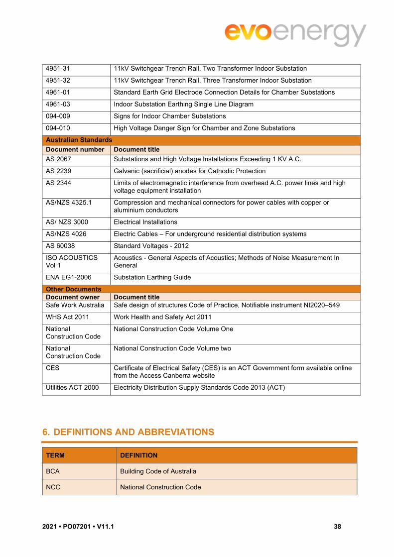
2021 • PO07201 • V11.1 38
4951-31 11kV Switchgear Trench Rail, Two Transformer Indoor Substation
4951-32 11kV Switchgear Trench Rail, Three Transformer Indoor Substation
4961-01 Standard Earth Grid Electrode Connection Details for Chamber Substations
4961-03 Indoor Substation Earthing Single Line Diagram
094-009 Signs for Indoor Chamber Substations
094-010 High Voltage Danger Sign for Chamber and Zone Substations
Australian Standards
Document number Document title
AS 2067 Substations and High Voltage Installations Exceeding 1 KV A.C.
AS 2239 Galvanic (sacrificial) anodes for Cathodic Protection
AS 2344 Limits of electromagnetic interference from overhead A.C. power lines and high voltage equipment installation
AS/NZS 4325.1 Compression and mechanical connectors for power cables with copper or aluminium conductors
AS/ NZS 3000 Electrical Installations
AS/NZS 4026 Electric Cables – For underground residential distribution systems
AS 60038 Standard Voltages - 2012
ISO ACOUSTICS Vol 1
Acoustics - General Aspects of Acoustics; Methods of Noise Measurement In General
ENA EG1-2006 Substation Earthing Guide
Other Documents Document owner Document title Safe Work Australia Safe design of structures Code of Practice, Notifiable instrument NI2020–549
WHS Act 2011 Work Health and Safety Act 2011
National Construction Code
National Construction Code Volume One
National Construction Code
National Construction Code Volume two
CES Certificate of Electrical Safety (CES) is an ACT Government form available online from the Access Canberra website
Utilities ACT 2000 Electricity Distribution Supply Standards Code 2013 (ACT)
6. DEFINITIONS AND ABBREVIATIONS
TERM DEFINITION
BCA Building Code of Australia
NCC National Construction Code

2021 • PO07201 • V11.1 39
FRL Fire Resistance Level, as per definition in the Building Code of Australia
RCD Residual Current Device
Substation Chamber; Room housing equipment for termination and connection of transmission and distribution lines containing any one, or a combination of the following apparatus: - transformers, HV switchgear, LV switchgear, DC battery bank, metering and control equipment
Below Ground Chamber Substation
All ‘indoor substations’ where access is gained below the footpath or roadway level, shall, for the purposes of this guideline, be treated as ‘Below Ground Chamber’ substations.
Customer/ Contractor Building owner or agents, building tenants or electricity consumer
Project Officer Engineer or Technical Officer representing Evoenergy in designing the substation.
Substation Requirements
A drawing produced by Evoenergy Project Officer specific to the substation chamber design.
Standard Drawing One of the drawings detailing Evoenergy’s standard requirements for the provision of a substation chamber
Earth grid The earthing system associated with the substation chamber only. It consists of interconnected multiple earth electrodes.
Switchgear Switching equipment on the high voltage and low voltage distribution system
VERSION CONTROL
VERSION DETAIL APPROVED
5.0 Updated; Fabian Tamp, Bhavin Suthar Wayne Cleland; John Garvin; Janusz Worony; 20 Jan 12
6.0 Clauses 3.6 & 5.2 amended to include new completion dates and customer responsibility; M. Vodvarka
B Suthar; 14 Sept 12
7.0 Updated table to contents (Administrative change); B. Suthar
Wayne Cleland; 15 Aug 14
8.0 Formatting of the whole document; J Atanasievska
Wahid Ibrahim; 18 Sep 15
9.0 Changes to align contents with applicable standards and codes, current AAD practice; B.Bramanathan
Wahid Ibrahim; 05 Dec 17
10.0 Basement and hatchway access removed B. Brama; N. Azizi; W. Cleland; 10 Oct 2020

2021 • PO07201 • V11.1 40
11.0 Updated Appx. B – Siting checklist and Appx. C – handover Checklist incl. feedback from Major Projects Team
M. Senanayake; N. Azizi; 2 June 2021
11.1 Updated section 3.7.6, 3.24.2, 3.25.3, 2.25.6 & 3.35
K. Vedanti; N. Azizi; 18 Oct 2021
DOCUMENT CONTROL
DOCUMENT OWNER PUBLISH DATE REVIEW DATE
Group Manager Strategy and Operations
18/10/2021 18/10/2023

2021 • PO07201 • V11.1 41
APPENDIX A – REDUCING THE RISKS OF ARCING FAULTS IN CUSTOMERS' INSTALLATIONS
Note: These requirements are mandatory.
This Appendix outlines requirements to reduce the risk and adverse effects of high impedance arcing faults on customer's large main switchboards and consumers mains (heavy current circuits), which are supplied directly from an Evoenergy substation.
Heavy current circuits are regarded as those were the nominal rated current carrying capacity of the switchboard is 800A or more per phase.
The safety risks of arcing faults are potentially catastrophic and include death or serious injury to personnel in the vicinity, destruction or severe damage to the customer’s consumer’s mains, main switchboard, building etc. and resultant financial and business loss.
Predominant causes of these faults include unsafe work practices, lack of maintenance or inadequate design e.g. working live on main switchboards and contamination of these switchboards with dust, dirt, moisture, vermin etc.
The protection schemes practically available to Evoenergy at its substations are not designed to protect against the adverse effects of arcing faults at the Customers' main switchboards. Customers must take all reasonable precautions in the design, installation, operation and maintenance of their electrical installation to minimise the risk of occurrence and adverse effects of arcing faults.
For the purposes of this Network Standard, the arcing fault current is deemed to be in the range of 30% to 60% of the prospective three phase short circuit current. The 30% value includes arcing faults to earthed metal.
The terms “safety services” and “safety circuits” refer to fire and life safety services or circuits, which have been commonly referred to as Essential or Emergency services.
Essential Requirements Protection against arcing fault currents shall be provided for heavy current switchboards whilst the equipment is in service or is undergoing maintenance.
The requirements for protection are as follows:
1. The Consumers Mains shall be constructed to reduce the probability of arcing faults within the customer’s installation
2. This is also a requirement of Evoenergy for all installations supplied directly from a dedicated low voltage circuit originating within an Evoenergy substation.
3. No Live Work shall be carried out except where specifically permitted
4. Safety Signage shall be provided
5. The switchboard shall comply with at least one of the following:
The installation’s Main Switchboard shall be provided with a Service Protective Device (SPD) selected and set to limit as far as possible the harmful effects of a switchboard internal arcing fault.
The Main Switchboard shall be constructed to reduce the probability of arcing faults within the customer’s installation.
Limiting the harmful effects of internal arcing faults
A circuit breaker providing protection against both overload and short-circuit current must be installed as a Service Protective Device (SPD) within the customer’s main switchboard for heavy current circuit installations.

2021 • PO07201 • V11.1 42
Note: Evoenergy also requires the installation of a circuit breaker SPD providing protection against both overload and short-circuit current for all switchboards supplied directly from a dedicated low voltage circuit originating within an Evoenergy substation.
Alternatives to this SPD arrangement may be approved in specific circumstances.
The service protective device (circuit breaker) need not be regarded as a general installation main switch in terms of AS/NZS 3000. In this instance, the SPD must be capable of operation only by authorised persons and marked accordingly
The incoming connections on the SPD circuit breaker must be fully insulated as these connections may not be protected against arcing faults and the SPD must be within a sealable compartment providing the internal separation. If safety services are fed from the main switchboard, the SPD circuit breaker shall be locked in the ‘on’ position and labelled accordingly.
To minimise damage to the consumer’s mains and main switchboard, the SPD circuit breaker shall be selected and set to initiate at a current less than 30% of the prospective three phase short circuit (fault) current and to clear an arcing fault at the customer's main switchboard in accordance with the following maximum clearing time and discrimination criteria. Acceptable protection methods will vary according to the specific circumstances; they may include Overcurrent and Short Circuit, Ground Fault, or a combination of these.
Artificial mechanisms for overcoming these requirements, such as the installation adjacent to the substation of a nominal main switchboard where significant load splitting and protection sensitivity improvement does not occur, will not be accepted unless protection on the outgoing mains and downstream switchboard(s) is also in accordance with this guideline.
Clearing time:
t = ke x Ir
If1.5
Where: t = clearing time in seconds
If = 30% of the prospective fault current
Ir = current rating of the switchboard
ke = 250 constant, based on acceptable volume damage as assumed in NEMA PB 2.2-1999.
Example: The minimum arcing fault clearing time at a customer’s 800A rated main switchboard with a prospective fault current at the switchboard of 16.67 kA. Therefore:
If = 30% of 16.67 kA = 5kA.
t = 250 x 800 = 0.57 seconds
50001.5
i.e. The SPD protection settings must be set to clear an arcing fault of 5kA in less than 0.57 seconds.
Discrimination:
The SPD shall also be selected and set such that:
1. It grades (discriminates) with Evoenergy’s substation protection equipment fuse or circuit breaker, to the requirements of Evoenergy,
2. A fault on the general electrical installation will not result in loss of supply to safety services, and
3. A fault on one safety circuit will not result in loss of supply to other safety circuits.
For the purposes of this Network Standard, the discrimination requirements for 2) & 3) above are intended to apply only up to the level of an arcing fault, which is deemed to be 60% of the 3 phase prospective short-

2021 • PO07201 • V11.1 43
circuit current, so as to comply with AS/NZS 3000. Compliance with any other relevant standards remains a requirement.
Information on the characteristics of Evoenergy’s protection equipment and values of prospective short-circuit current will be provided upon application to Evoenergy.
Reducing the probability of arcing faults within the customer’s installation
The Consumer’s Mains and Main Switchboard shall be constructed to reduce the probability of arcing faults within the customer’s installation as described above.
Consumer’s Mains
The consumer’s mains up to the line side of the SPD shall be provided with means to reduce the probability of initiation of arcing faults by insulation or by separation.
The following are deemed to satisfy this requirement:
1. Insulated and sheathed cables arranged with mechanical protection complying with AS/NZS 3013 with a WSX2 classification.
2. Underground wiring or fire rated wiring enclosures to AS/NZS 3000.
3. Supply busways with insulated busbars, including joints, and switchboard busbars with insulation or separation up to the first protective device(s) in accordance with AS/NZS 61439.
Main Switchboard
A main switchboard that is in service or undergoing maintenance must be capable of reducing the probability of initiation of an arcing fault. This may be achieved by constructing the main switchboard to provide internal separation in accordance with AS/NZS 61439.1 for all of the following:
1. Busbars from functional units
2. Functional units from one another
3. Terminals provided for external conductors from the busbar
4. The safety service circuits section from the general installation circuits section
5. Busbars in trunking systems (busways)
Note
1. Forms 3b, 4a, and 4b of AS/NZS 61439.0 achieve these requirements, provided item d) is incorporated.
2. For separation using these Forms, the required degree of protection, IP2X or IP1XB, is to prevent the entry of objects and contact with live parts by a person’s finger. To prevent the entry of tools or wires the degree of protection may be increased (i.e. small tools IP3X or IP2XC [2.5mm diameter] and wires IP4X or IP3XD [1mm diameter]).
3. Separation in accordance with AS/NZS 61439.1 may be achieved by the insulation of busbars, the use of barriers, or by insulated housings. (i.e. by the use of a Form 3bi, Form 3bh, Form 3bih, Form 4ah, Form 4aih, or Form 4bi, Form 4bh, Form 4bih constructed switchboard,).
No Live Work
Clause 207 of the Occupational Health and Safety Regulation, 2011 and the supporting WorkCover Code of Practice - Low Voltage Electrical Work specifies that electrical work must not be carried out while that part of the electrical installation’s circuits and apparatus to be worked on are energised (live).
It is the responsibility of the employer, and the controller of the premises, to ensure that this is not done other than in situations where it is necessary in the interests of safety and the risk of harm would be greater if that part of the installation’s circuits or apparatus were to be de-energised.
For work on the line side of the customer’s SPD or otherwise requiring interruption to the supply from the substation, arrangements must be made well in advance with Evoenergy (minimum of 10 working days), to provide isolation of the supply at the substation and a Clearance to Work.
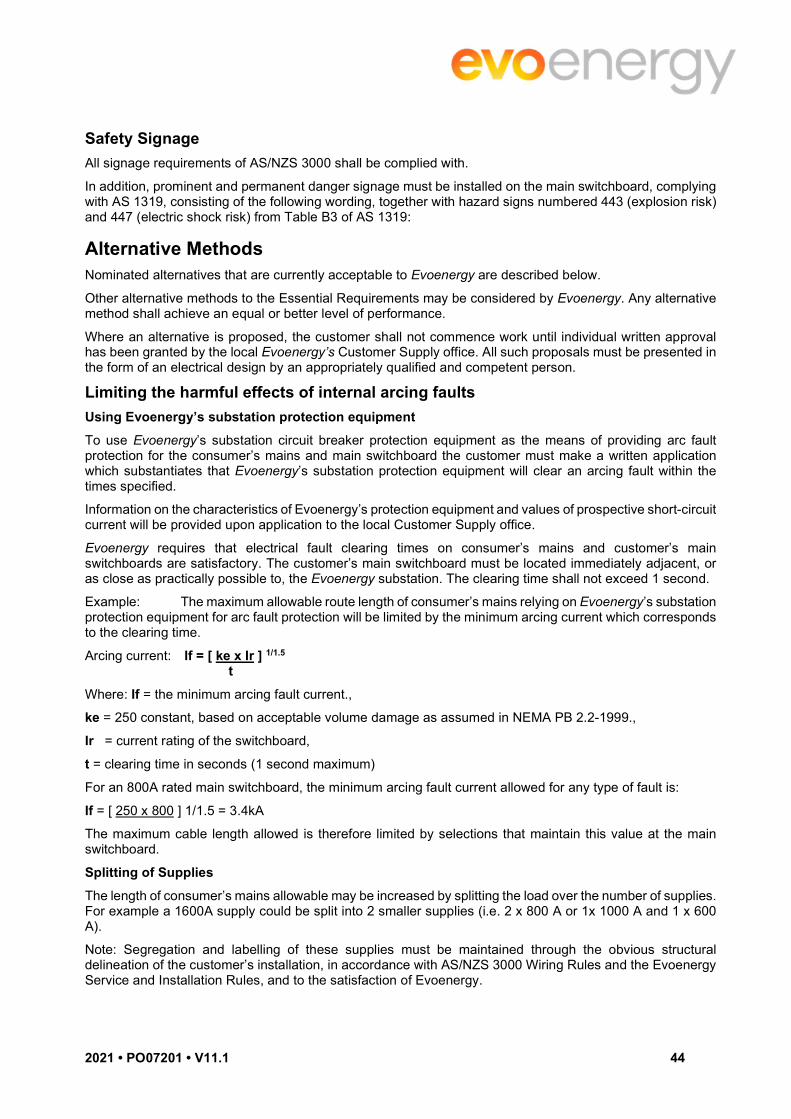
2021 • PO07201 • V11.1 44
Safety Signage
All signage requirements of AS/NZS 3000 shall be complied with.
In addition, prominent and permanent danger signage must be installed on the main switchboard, complying with AS 1319, consisting of the following wording, together with hazard signs numbered 443 (explosion risk) and 447 (electric shock risk) from Table B3 of AS 1319:
Alternative Methods Nominated alternatives that are currently acceptable to Evoenergy are described below.
Other alternative methods to the Essential Requirements may be considered by Evoenergy. Any alternative method shall achieve an equal or better level of performance.
Where an alternative is proposed, the customer shall not commence work until individual written approval has been granted by the local Evoenergy’s Customer Supply office. All such proposals must be presented in the form of an electrical design by an appropriately qualified and competent person.
Limiting the harmful effects of internal arcing faults
Using Evoenergy’s substation protection equipment
To use Evoenergy’s substation circuit breaker protection equipment as the means of providing arc fault protection for the consumer’s mains and main switchboard the customer must make a written application which substantiates that Evoenergy’s substation protection equipment will clear an arcing fault within the times specified.
Information on the characteristics of Evoenergy’s protection equipment and values of prospective short-circuit current will be provided upon application to the local Customer Supply office.
Evoenergy requires that electrical fault clearing times on consumer’s mains and customer’s main switchboards are satisfactory. The customer’s main switchboard must be located immediately adjacent, or as close as practically possible to, the Evoenergy substation. The clearing time shall not exceed 1 second.
Example: The maximum allowable route length of consumer’s mains relying on Evoenergy’s substation protection equipment for arc fault protection will be limited by the minimum arcing current which corresponds to the clearing time.
Arcing current: If = [ ke x Ir ] 1/1.5
t
Where: If = the minimum arcing fault current.,
ke = 250 constant, based on acceptable volume damage as assumed in NEMA PB 2.2-1999.,
Ir = current rating of the switchboard,
t = clearing time in seconds (1 second maximum)
For an 800A rated main switchboard, the minimum arcing fault current allowed for any type of fault is:
If = [ 250 x 800 ] 1/1.5 = 3.4kA
The maximum cable length allowed is therefore limited by selections that maintain this value at the main switchboard.
Splitting of Supplies
The length of consumer’s mains allowable may be increased by splitting the load over the number of supplies. For example a 1600A supply could be split into 2 smaller supplies (i.e. 2 x 800 A or 1x 1000 A and 1 x 600 A).
Note: Segregation and labelling of these supplies must be maintained through the obvious structural delineation of the customer’s installation, in accordance with AS/NZS 3000 Wiring Rules and the Evoenergy Service and Installation Rules, and to the satisfaction of Evoenergy.

2021 • PO07201 • V11.1 45
Additional Protection Schemes
Installation of additional protection schemes on the consumer’s mains and main switchboard may be proposed for use in conjunction with Evoenergy’s standard protection in the substation (for example, unit protection such as Translay and differential). Evoenergy recommends that customers seek prior expert advice on the application of such schemes, due to their complexity and risk of nuisance tripping.

2021 • PO07201 • V11.1 46
APPENDIX B – CHAMBER SUBSTATION SITING CHECKLIST
NO. DESCRIPTION REFERENCE CRITERION MET / COMMENT BY DEVELOPER’S ARCHITECT OR DESIGNER
ACCEPTABLE TO EVOENEGY OR COMMENTS
GENERAL HEALTH SAFETY AND ENVIRONMENT
1. Environmental Protection Management Plan (EPMP) or Environmental Impact Statement (EIS) available detailing sites for cultural sensitivity, significant trees and threatened species.
CL 3.2
2. The site is free from Asbestos related products and other polluted material
CL 3.34
GENERAL SITING AND ACCESS
3. Substation shall be located on ground level.
If not, ‘Below Ground’ substations require prior approval from Evoenergy.
CL 1
4. 24 hour dedicated access as per Utilities Act 2000 and unhindered access for emergency evacuation.
CL 3.4
5. 1200mm wide dedicated access way provided CL 3.4
6. No public or occupant access must be through the Evoenergy dedicated access ways
CL 3.4
7. All access ways must be located to ensure egress and ingress from or onto a public street or an all-weather heavy-duty access roadway which complies with the BCA egress and ingress requirements
CL 3.4
8. The substation chamber located in an area free of other building services other than those directly relating to the substation
CL 3.4.1
9. Substation area is free of any obstructions, structures or services which could interfere with the installation of any part of the earthing system.
Cl 3.4.1

2021 • PO07201 • V11.1 47
47 of 58
10. Site is geotechnically stable and certified by a geotechnical engineer CL 3.4.1
11. Structure of the substation or chamber is certified, as being designed to Australian Standards which provides a 50-year life cycle
CL 3.4.1
12. Any services including, but not limited to, stormwater, sewers, gas, water, fire services, air-conditioning installations, electrical or communications cables, conduits or pipe work other than those specified by Evoenergy, must not encroach into the substation site area
CL 3.4.1
13. Columns, beams, footings or any part of any other building or structure shall not encroach on the clearances required in the chamber substation
CL 3.4.1
14. Substation is not located;
Where the average humidity over a day exceeds 95%. Where the ambient air has high levels of dust, smoke,
combustible or corrosive pollutants Where there is concern over vibration
CL 3.4.2
15. No other building or structure other than the substation is within 3 metres in any direction from the ventilation openings of the chamber substation
CL 3.4.2
16. Minimum 3-metre-wide area or driveway to the substation chamber is provided
CL 3.4.5
17. Substation floor shall be above the 100-year flood level. CL 3.4.5
18. The access route slope must not exceed 1:12 CL 3.4.5
19. The access route must have minimum headroom of 5.5 metres CL 3.4.5
20. The area outside the entrance to the substation shall have a minimum clear height of 6 metres
CL 3.4.5

2021 • PO07201 • V11.1 48
48 of 58
21. A 2.5m wide loading area along the full face of the chamber containing doors, with 1:100 fall away (No fall along the full length of the front face of the chamber)
CL 3.4.5
22. Substation chamber and access to it shall not be located in a hazardous area as classified in AS/NZS 3000
CL 3.4.8
ELECTROMAGNETIC FIELDS
23. Impact on electromagnetic radiation from the chamber substation equipment to the adjacent or above indoor chamber substation is considered
CL3.5
DRAWINGS
24. The architect shall provide Evoenergy with the following drawings in AutoCAD format (electronically)
Overall site plan which indicates the chamber substation and customer’s switch room to Stromlo Coordinates
Detailed plan of the proposed chamber and the access routes to the chamber
CL 3.7
EARTHING
25. Soil resistivity test was carried out at the substation site and used these readings to design an earth grid.
CL 3.11
26. Easement or areas required for earth cables included in the lease and easement documentation for the Chamber Substation
CL 3.11
LIGHTNING PROTECTION
27. Requirement for a “Lightning Protection” risk assessment in accordance to AS/NZS 1768
CL 3.12
Additional Notes:
_______________________________________________________________________________________________________________________

2021 • PO07201 • V11.1 49
49 of 58
_______________________________________________________________________________________________________________________
_______________________________________________________________________________________________________________________
_______________________________________________________________________________________________________________________
_______________________________________________________________________________________________________________________
_______________________________________________________________________________________________________________________
Submitted by: ________________________________________________ Date: _________________

2021 • PO07201 • V11.1 50
50 of 58
APPENDIX C – CHAMBER SUBSTATION HANDOVER REPORT
NO. ITEM REFERENCE ACCEPTABLE / NOT ACCEPTABLE
COMMENTS
GENERAL ACCESS
1. 24Hrs x 365 days dedicated access CL 3.4
2. Access way width of 1200mm CL 3.4
3. PA doors are not to open directly onto a driveway/roadway unless bollards have been installed to prevent vehicles passing or parking within 1.2m
CL 3.4
4. Clear height of 6m outside equipment doors CL 3.4
5. No piping or storage of hazardous materials or volatile liquids in the vicinity of the substation. No volatile liquids or gases etc. near substation
CL 3.4
6. Adequately drained area to prevent ingress of water / moisture CL 3.4 & CL 3.20
7. Appropriate hardstand area for gear delivery CL 3.4
8. Car park access for construction team CL 3.4
ELECTROMAGNETIC FIELDS
9. If shielding to be constructed using non-flammable materials; avoid creation of condensation; maintenance free; solidly earthed to the substation earthed; and painted white or finished in a light colour
CL 3.5
ACOUSTIC LEVELS
10. Ambient noise level shall as low as reasonably practicable and not more than 85dB (A) for working in the substation
CL 3.6
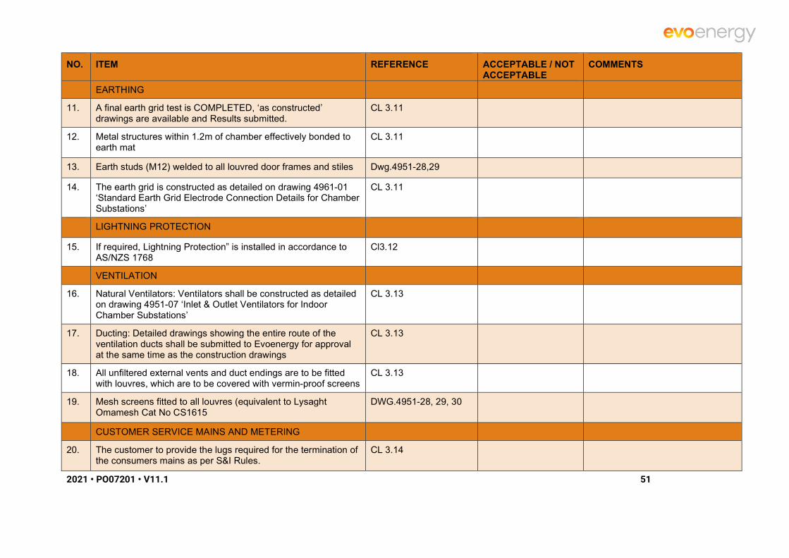
2021 • PO07201 • V11.1 51
51 of 58
NO. ITEM REFERENCE ACCEPTABLE / NOT ACCEPTABLE
COMMENTS
EARTHING
11. A final earth grid test is COMPLETED, ‘as constructed’ drawings are available and Results submitted.
CL 3.11
12. Metal structures within 1.2m of chamber effectively bonded to earth mat
CL 3.11
13. Earth studs (M12) welded to all louvred door frames and stiles Dwg.4951-28,29
14. The earth grid is constructed as detailed on drawing 4961-01 ‘Standard Earth Grid Electrode Connection Details for Chamber Substations’
CL 3.11
LIGHTNING PROTECTION
15. If required, Lightning Protection” is installed in accordance to AS/NZS 1768
Cl3.12
VENTILATION
16. Natural Ventilators: Ventilators shall be constructed as detailed on drawing 4951-07 ‘Inlet & Outlet Ventilators for Indoor Chamber Substations’
CL 3.13
17. Ducting: Detailed drawings showing the entire route of the ventilation ducts shall be submitted to Evoenergy for approval at the same time as the construction drawings
CL 3.13
18. All unfiltered external vents and duct endings are to be fitted with louvres, which are to be covered with vermin-proof screens
CL 3.13
19. Mesh screens fitted to all louvres (equivalent to Lysaght Omamesh Cat No CS1615
DWG.4951-28, 29, 30
CUSTOMER SERVICE MAINS AND METERING
20. The customer to provide the lugs required for the termination of the consumers mains as per S&I Rules.
CL 3.14

2021 • PO07201 • V11.1 52
52 of 58
NO. ITEM REFERENCE ACCEPTABLE / NOT ACCEPTABLE
COMMENTS
FIRE PROTECTION
21. Consumer mains conduits or penetrations in ceiling and walls are to maintain fire resistance
CL 3.15, CL3.29
22. One 4.5kg dry chemical type fire extinguishers and signs CL 3.15
23. Fire detection in chamber (Nil required) but dictated by BCA CL 3.13 & CL 3.15
24. CO2 Fire Suppression System as directed by ACT Fire Brigade CL 3.15
SUBSTATION LIGHT AND POWER
25. All conduits, GPO’s and light fittings shall be installed according to AS/NZS 3000, switches and GPOs to be wired with 2.5 mm2. cable in 25mm conduits
CL 3.17 & CL 3.17
26. The building contractor shall also provide a temporary power supply for the substation fit out within 10 metres of the chamber
CL 3.17
27. General power: is to be provided for a minimum of two single-phase, double, 10 amp 240 volt GPOs located as shown in the project requirement drawings
CL 3.17
28. Lighting: 36W bare batten fluorescent lights (or, preferably, equivalent LED luminaires); with minimum of 160 lux throughout a horizontal plane one metre above the floor level
CL 3.17
29. Light fittings must be installed at typical chamber ceiling height (i.e. not below 3.5 metres). Wall mounted light fittings shall be installed 2100 mm above floor level
CL 3.17
30. Lights are to be controlled by two-way heavy-duty switches positioned adjacent to each personnel access doorway.
CL 3.17
PERSONNEL BARRIERS

2021 • PO07201 • V11.1 53
53 of 58
NO. ITEM REFERENCE ACCEPTABLE / NOT ACCEPTABLE
COMMENTS
31. “Transformer Safety Barrier” are available to be installed CL 3.21 & Dwg. 4951-22
SERVICE PITS AND CONDUITS
32. Conduits installed per design drawings Chamber substation requirements drawings
33. Waterproofing membranes and the sealing of cable entries CL 3.4 & CL 3.20
34. No service pipes or conduits in substation chamber CL 3.22
35. Conduits plugged at both ends CL 3.22
36. Conduits embedded below the floor slab require a minimum 150mm concrete encasement.
Cl3.24
37. a minimum cover of 850mm to the conduit invert level, as per Evoenergy standard drawing 4931-06 “6 & 9 Way Conduit Entry to Chamber Substations Standard Configuration”
CL 3.26
38. All conduit ends inside the substation shall utilise a bell mouth flush with the trench wall or floor surface
CL 3.26
39. Conduits shall be provided and installed by the customer between the substation chamber and the property line
CL 3.26
40. Draw ropes through each conduit shall be provided. All conduits leaving the substation shall be sealed at all joints and plugged at both ends
CL 3.26
41. Where required, a separate 2 hour fire rated “water trap” chamber with suitable drainage must be provided
CL 3.26
CHAMBER DETAILS
42. Chamber Room Dimensions as per Evoenergy supplied drawing
Dwg.4921-06, 13, 14
43. No building columns shall be included within the substation chamber floor area
CL 3.24

2021 • PO07201 • V11.1 54
54 of 58
NO. ITEM REFERENCE ACCEPTABLE / NOT ACCEPTABLE
COMMENTS
44. Metal deck roof to be 2hr fire rated & 5m clear of other Buildings (Free Standing Chambers)
CL 3.24
45. The minimum clear headroom within the substation chamber shall be 3500mm
CL 3.24
46. The roof shall be constructed so that all drainage runs freely from the roof
CL 3.24
47. Ceiling of chambers minimum requirement for explosion resistance shall be 140mm thick reinforced concrete
CL 3.24
48. Walls of chambers minimum requirement for explosion resistance shall be 150mm thick reinforced concrete
CL 3.24
49. Walls: Where un-reinforced concrete, solid blocks or bricks or solid clay bricks are used, the walls shall be 190mm minimum in thickness for explosion resistance and comply with design guidelines
CL 3.24
50. Floor: Floor slabs and cable trenches shall be at min. 150mm thick reinforced concrete
CL 3.24
51. The floor shall be suitable to support the weight of a six (6) tonne transformer in each final transformer location
CL 3.24
52. The surface of the floor shall be clean and free of concrete and left bare (i.e. not sealed or painted).
CL 3.24
53. Floor to have smooth finish no abrupt level changes (level area shall be provided for Tx, LV & HV switchgear)
CL 3.24
DOORS AND LOUVERS
54. Access doorways width of 1000mm required CL 3.4
55. All fire rated doors are to be supplied certified and tagged with the fire rating
CL 3.25

2021 • PO07201 • V11.1 55
55 of 58
NO. ITEM REFERENCE ACCEPTABLE / NOT ACCEPTABLE
COMMENTS
56. The doors are to be solid core pressed metal folded type construction
CL 3.25
57. PA doors must be readily openable from the inside without a key and by a single hand push release (panic) bar located between 900 mm and 1200 m from the floor
CL 3.25
58. Ventilation louvres 'inverted V type' with two integral traps CL 3.25
Dwg.4951-7, 28, 29, 30
59. All substations must be provided with two separate personnel access (PA) doors, open outward
CL 3.25
Dwg.4951-23, 28, 29
60. Robust means of holding all doors open CL 3.25
61. Reclosers fitted to internal side of single personnel doors (Door closers shall be of 'Lockwood' 727 series or 'Dorma' TS73 ) parallel arm type
CL 3.25
Dwg.4951-23, 28
62. Personnel doors with escape lever; self-closing and latch into strike to lock with every operation
CL 3.25
Dwg.4951-23, 28
63. PA doors to (louvered) to be 2040mm x 1020mm (min) Dwg.4951-28
64. PA doors in fire rated wall to be 2040mm x 820mm (min) Dwg.4951-23
65. Equipment doors to be 3200mm x 2800mm Dwg.4951-29
66. Door Lock cylinders similar to Lockwood type 3570/2 on KB203/6 profile
CL 3.25
67. Latch Bolt- automatically locked when the door is closed, and dead latched
CL 3.25

2021 • PO07201 • V11.1 56
56 of 58
NO. ITEM REFERENCE ACCEPTABLE / NOT ACCEPTABLE
COMMENTS
68. All personnel, equipment and escape doorways shall have a phosphorescence metal Exit Sign above their opening complying with AS2293.3
CL 3.25
69. Supply of 100x100x600mm dense masonry bund CL 3.25
CABLE TRENCH
70. Haulage eyes are in accordance 4951-09 “Standard Substation Haulage & Lifting Eye” and located 200mm above the trench floor
CL 3.29
71. Drainage from the cable trench is not permitted and no other drainage system is to feed into the cable trench
CL 3.29
72. HV trench depth 900mm min and 1200mm max CL 3.29
Dwg.4931-01, 03, 11
73. LV trench depth 600mm min and 1200mm max CL 3.29
Dwg.4931-01, 03, 11
74. Minimum slope of 1 in 60 to the sump CL 3.29
Dwg.4931-01, 03, 11
75. Switchgear support beam level and distance from trench wall Dwg.4951-31
76. Trench rails - correct number and fabricated as per Evoenergy specifications
Dwg.4931-02
TRENCH COVER PLATES AND PLATE LIFTING KEYS
77. Checker plate covers are to be supplied to fit over the open sections of the cable trench
Aluminium checker plate and not less than 6mm thick. Maximum area of any plate shall be 1 m2. The cover must weigh less than 20 Kg.
CL 3.30

2021 • PO07201 • V11.1 57
57 of 58
NO. ITEM REFERENCE ACCEPTABLE / NOT ACCEPTABLE
COMMENTS
Plates are to be straight and flat and finish flush with the floor
78. Each plate is to have two oval shaped lifting slots (10 x 30mm) CL 3.30
79. Heavy duty cover plates to allow safe movement of personnel and machinery traffic during substation fit out
CL 3.30; Dwg 4931-13 and Dwg 4931-14
PAINTING AND FINISHING
80. The interior walls and ceiling to be finished with a plastic based semi-gloss paint, colour –white to AS 2700S-1996(N14) ‘Colour Standards for general purposes – White’
CL 3.31
81. One litre of this paint in a suitable sealed tin shall be left in the chamber
CL 3.31
HOLD POINTS
82. HOLD POINT: Evoenergy inspected the earth grid and tested during construction
Cl3.11 & Cl3.10
83. HOLD POINT: Pre concrete pour (Floor) - showing earth tail braising and grading ring and required reference tails in HV, LV trench and checking conduits
Cl3.22 & Cl3.10
84. HOLD POINT: Final handover inspection CL 4.1
MISCELLANEOUS ITEMS
85. Induction requirements advised to Evoenergy prior to handover
86. …………………………………………… As required
87. …………………………………………… As required
88. …………………………………………… As required
89. …………………………………………… As required

2021 • PO07201 • V11.1 58
58 of 58
Note: The following items will require attention before Evoenergy will accept the chamber:
_______________________________________________________________________________________________________________________
_______________________________________________________________________________________________________________________
_______________________________________________________________________________________________________________________
_______________________________________________________________________________________________________________________
_______________________________________________________________________________________________________________________
Inspected by: ________________________________________________ Date: ________________