analysis of an electrical power injection substation analysis of ...
14
Oshevire Patrick & Oshevire Patrick & Oshevire Patrick & Oshevire Patrick & Usiholo Iruansi Usiholo Iruansi Usiholo Iruansi Usiholo Iruansi | | | | 15 15 15 15 International Journal of Engineering and Emerging Scientific Discovery International Journal of Engineering and Emerging Scientific Discovery International Journal of Engineering and Emerging Scientific Discovery International Journal of Engineering and Emerging Scientific Discovery ISSN: 2536 ISSN: 2536 ISSN: 2536 ISSN: 2536-7250 (Print): 2536 7250 (Print): 2536 7250 (Print): 2536 7250 (Print): 2536-7269 (Online) 7269 (Online) 7269 (Online) 7269 (Online) Volume 3, Number 2, June 2018 Volume 3, Number 2, June 2018 Volume 3, Number 2, June 2018 Volume 3, Number 2, June 2018 http://www.casirmediapublishing.com http://www.casirmediapublishing.com http://www.casirmediapublishing.com http://www.casirmediapublishing.com ANALYSIS OF AN ELECTRICAL POWER INJECTION SUBSTATION ANALYSIS OF AN ELECTRICAL POWER INJECTION SUBSTATION ANALYSIS OF AN ELECTRICAL POWER INJECTION SUBSTATION ANALYSIS OF AN ELECTRICAL POWER INJECTION SUBSTATION 1 Oshevire Patrick shevire Patrick shevire Patrick shevire Patrick & 2 Usiholo Iruansi Usiholo Iruansi Usiholo Iruansi Usiholo Iruansi 1 Department of Electrical and Electronics Engineering, Federal University of Petroleum Resources, Effurun, Delta State 2 Department of Computer Engineering, Faculty of Engineering, University of Benin, Benin City, Edo State E-mail: mail: mail: mail: [email protected]; [email protected] Corresponding author: Corresponding author: Corresponding author: Corresponding author: Usiholo Iruansi ABSTRACT ABSTRACT ABSTRACT ABSTRACT Distribution systems hold an extremely critical position in the power system since its primary point of link is between bulk power and consumers. An effective and planned distribution network is the way to adapt with the ever increasing demand for commercial, domestic and industrial load. The power flow or load-flow study of radial distribution network is of prime significance for effective planning and execution of load transfers. Power companies are keen on finding the most efficient configuration for minimization of real power loses and load balancing among distribution feeders to save energy and in improving the general performance of distribution system. Keywords: Keywords: Keywords: Keywords: Distributed Generation (DG), Power Tools for Windows (PTW), Power flow study, load flow study. INTRODUCTION INTRODUCTION INTRODUCTION INTRODUCTION Electric power supply is the most essential commodity for national development. With electrical energy the populaces are enabled to work from the domestic level, the cottage industries, through the small-scale and medium industries to employment in the large-scale manufacturing business. In nowadays, depriving this populace of electric power is tantamount to castration [1]. Electric power generation may be gotten through any one of the following sources of energy; solar voltaic generator, coal, water – wave turbine or solar-wind, oil or natural gas, solar thermal generator, nuclear power (steam turbine) and hydro power (water turbine). Gas, hydro power, Coal and oil are inexhaustible in Nigeria. Presently Nigeria mostly employs hydroelectric turbines and gas-fired for bulk generation, oil being excessively costly and coal-fired stations having gone doomed [2]. Electrical power system provides an important and vital service to the society. It ought to be operated with the goal of achieving highest reliability standards, environmental impacts and minimum operational costs. Power systems are stochastic, complex, nonlinear and dynamic systems. With the increasing and ever expanding network connections power systems have been growing in complexity and size [3]. Power-flow (Load flow) study is the steady-state analysis of an interconnected power system during normal working conditions and it gives the required data with respect to power flowing through transmission and distribution lines and bus voltages, transformers and other different components of power system
-
Upload
khangminh22 -
Category
Documents
-
view
1 -
download
0
Transcript of analysis of an electrical power injection substation analysis of ...

Oshevire Patrick &Oshevire Patrick &Oshevire Patrick &Oshevire Patrick & Usiholo IruansiUsiholo IruansiUsiholo IruansiUsiholo Iruansi | | | | 15151515
International Journal of Engineering and Emerging Scientific DiscoveryInternational Journal of Engineering and Emerging Scientific DiscoveryInternational Journal of Engineering and Emerging Scientific DiscoveryInternational Journal of Engineering and Emerging Scientific Discovery ISSN: 2536ISSN: 2536ISSN: 2536ISSN: 2536----7250 (Print): 25367250 (Print): 25367250 (Print): 25367250 (Print): 2536----7269 (Online)7269 (Online)7269 (Online)7269 (Online)
Volume 3, Number 2, June 2018Volume 3, Number 2, June 2018Volume 3, Number 2, June 2018Volume 3, Number 2, June 2018 http://www.casirmediapublishing.comhttp://www.casirmediapublishing.comhttp://www.casirmediapublishing.comhttp://www.casirmediapublishing.com
ANALYSIS OF AN ELECTRICAL POWER INJECTION SUBSTATIONANALYSIS OF AN ELECTRICAL POWER INJECTION SUBSTATIONANALYSIS OF AN ELECTRICAL POWER INJECTION SUBSTATIONANALYSIS OF AN ELECTRICAL POWER INJECTION SUBSTATION
1111OOOOshevire Patrickshevire Patrickshevire Patrickshevire Patrick &&&& 2222Usiholo IruansiUsiholo IruansiUsiholo IruansiUsiholo Iruansi
1Department of Electrical and Electronics Engineering, Federal University of Petroleum Resources, Effurun, Delta State 2Department of Computer Engineering, Faculty of Engineering, University of Benin, Benin City, Edo State
EEEE----mail:mail:mail:mail: [email protected]; [email protected] Corresponding author:Corresponding author:Corresponding author:Corresponding author: Usiholo Iruansi
ABSTRACTABSTRACTABSTRACTABSTRACT Distribution systems hold an extremely critical position in the power system since its primary point of link is between bulk power and consumers. An effective and planned distribution network is the way to adapt with the ever increasing demand for commercial, domestic and industrial load. The power flow or load-flow study of radial distribution network is of prime significance for effective planning and execution of load transfers. Power companies are keen on finding the most efficient configuration for minimization of real power loses and load balancing among distribution feeders to save energy and in improving the general performance of distribution system. Keywords:Keywords:Keywords:Keywords: Distributed Generation (DG), Power Tools for Windows (PTW), Power flow study, load flow study.
INTRODUCTIONINTRODUCTIONINTRODUCTIONINTRODUCTION Electric power supply is the most essential commodity for national development. With electrical energy the populaces are enabled to work from the domestic level, the cottage industries, through the small-scale and medium industries to employment in the large-scale manufacturing business. In nowadays, depriving this populace of electric power is tantamount to castration [1]. Electric power generation may be gotten through any one of the following sources of energy; solar voltaic generator, coal, water – wave turbine or solar-wind, oil or natural gas, solar thermal generator, nuclear power (steam turbine) and hydro power (water turbine). Gas, hydro power, Coal and oil are inexhaustible in Nigeria. Presently Nigeria mostly employs hydroelectric turbines and
gas-fired for bulk generation, oil being excessively costly and coal-fired stations having gone doomed [2]. Electrical power system provides an important and vital service to the society. It ought to be operated with the goal of achieving highest reliability standards, environmental impacts and minimum operational costs. Power systems are stochastic, complex, nonlinear and dynamic systems. With the increasing and ever expanding network connections power systems have been growing in complexity and size [3]. Power-flow (Load flow) study is the steady-state analysis of an interconnected power system during normal working conditions and it gives the required data with respect to power flowing through transmission and distribution lines and bus voltages, transformers and other different components of power system
Oshevire Patrick &Oshevire Patrick &Oshevire Patrick &Oshevire Patrick & Usiholo IruansiUsiholo IruansiUsiholo IruansiUsiholo Iruansi | | | | 16161616
Analysis of an Electrical Power Injection SubstationAnalysis of an Electrical Power Injection SubstationAnalysis of an Electrical Power Injection SubstationAnalysis of an Electrical Power Injection Substation
for a specified load demand subject to the regulation capabilities of generators, condensers, phase shifting transformers and tap changing transformers. Power-flow studies, also referred to as load flow, are essential for power system design and analysis. Power flow studies are necessary for planning, operation, scheduling, economic and exchange of power between utilities. Load flow study is likewise required for many other analyses such as; state estimation, transient stability, contingency and dynamic stability [4]. Through the load flow studies also, the voltage magnitudes and angles at each bus in the steady state can easily be acquired. [5]. Power load-flow analysis is carried out to find the sensitivity of feeder status with variation of power loading, total capacity of distribution transformers and conductor length. They are used to guarantee that electrical power being transferred from generator to consumers through the grid system is economical, stable and reliable. The significant objective of a power flow study is to investigate that all bus-bars voltage are within specified limits and that the flow of reactive power is reasonable as to ensure that acceptable quality of service could be provided for the consumers. The design, planning and operation of power systems require load flow computations to analyze the steady – state performance of the
power system under various operating conditions and to study the effects of changes in equipment configuration. These load flow studies can be performed using computer programs designed specifically for this reason [6]. In this paper the load flow analysis and reliability evaluation of a 15MVA injection substation is analyzed. For the load flow Newton Raphson iterative method is utilized. Reliability indices were calculated using the Power Tools for Windows (PTW) Software. LITERATURE SURVEYLITERATURE SURVEYLITERATURE SURVEYLITERATURE SURVEY Power flow analysis is generally used by power distribution companies during the planning and operation of power distribution system. Mainly three methods are there for load flow- Newton Raphson, Gauss Seidel and Fast Decoupled [7]. In 1967, the traditional Newton based power flow solution method was developed. Later work by Stott and Alsacmade the fast decoupled Newton strategy. The algorithm made in 1967 remains unchanged for various applications. Despite the fact that this method functioned well for transmission systems, yet its convergence execution is poor for most distribution systems because of their high R/X ratio which deteriorates the diagonal dominance of the Jacobian matrix. Hence, different other types of methods have been introduced. Those strategies consist of forward / backward sweeps on a ladder
Oshevire Patrick &Oshevire Patrick &Oshevire Patrick &Oshevire Patrick & Usiholo IruansiUsiholo IruansiUsiholo IruansiUsiholo Iruansi | | | | 17171717
International Journal of Engineering and Emerging Scientific DiscoveryInternational Journal of Engineering and Emerging Scientific DiscoveryInternational Journal of Engineering and Emerging Scientific DiscoveryInternational Journal of Engineering and Emerging Scientific Discovery Volume 3, Number 2,Volume 3, Number 2,Volume 3, Number 2,Volume 3, Number 2, June 2018June 2018June 2018June 2018
system. The formulation of the algorithm for those strategies were unique from the Newton’s power flow method, which made those techniques difficult to be extended to different applications in which the Newton strategy appeared more suitable [8][9]. A Newton like procedure for solving ill-conditioned power systems is introduced. The method showed voltage convergence but could not be efficiently used for optimal power flow calculations [10]. A proposed three distinct algorithms for solving radial distribution systems in view of the technique proposed in 1967. The researcher likewise proposed decoupled, fast decoupled and very fast decoupled distribution load-flow algorithms. Truth be told decoupled and fast decoupled distribution load-flow algorithms were slow in convergence [11][12]. A new load-flow technique for getting the solution of radial distribution networks was proposed. Three fundamental equations representing real power, reactive power and voltage magnitude were used. It had solved the radial distribution network using the three equations by reducing the entire network into a single equivalent [13]. An approach for power flow solutions to obtain a reliable convergence in distribution systems was presented. The trigonometric terms were eliminated in the node power expressions and thereby the resulting equations were partially linearized for
obtaining better convergence. The method was simpler than existing approaches and solved iteratively similar to Newton-Raphson (NR) technique [14].
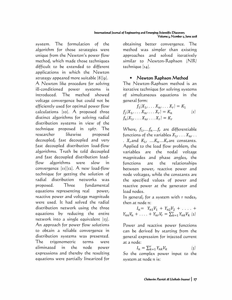
• Newton Raphson MethodNewton Raphson MethodNewton Raphson MethodNewton Raphson Method The Newton-Raphson method is an iterative technique for solving systems of simultaneous equations in the general form: ��(��, . . . ��, . . . ��) = �� ��(��, . . . ��, . . . ��) = �� (1)
��(��, . . . ��, . . . ��) = �� Where, ��,....��....�� are differentiable functions of the variables ��, . . . ��, . . . ��and ��, ....��....��are constants. Applied to the load flow problem, the variables are the nodal voltage magnitudes and phase angles, the functions are the relationships between power, reactive power and node voltages, while the constants are the specified values of power and reactive power at the generator and load nodes. In general, for a system with r nodes, then at node n: ��= ��� + ��� + . . . . + ��� + . . . . + ��� = ∑ � � �� (2) Power and reactive power functions can be derived by starting from the general expression for injected current at a node: �� = ∑ � � �� (3) So the complex power input to the system at node n is:
Oshevire Patrick &Oshevire Patrick &Oshevire Patrick &Oshevire Patrick & Usiholo IruansiUsiholo IruansiUsiholo IruansiUsiholo Iruansi | | | | 18181818
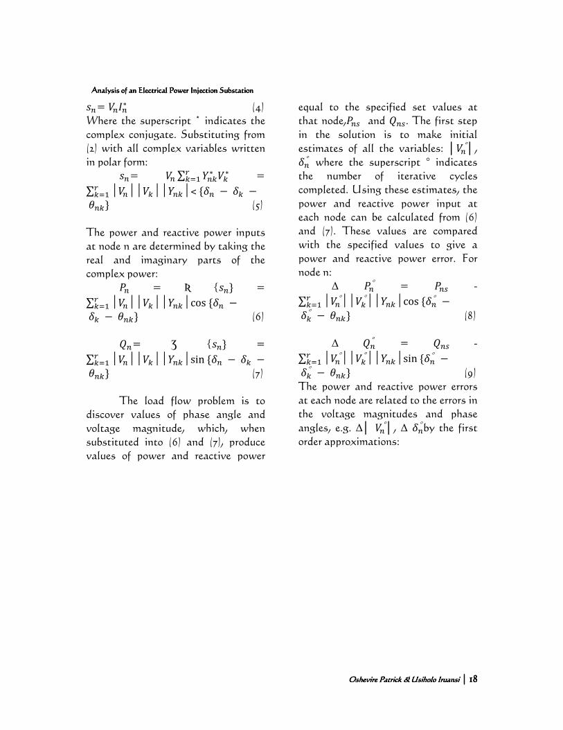
Analysis of an Electrical Power Injection SubstationAnalysis of an Electrical Power Injection SubstationAnalysis of an Electrical Power Injection SubstationAnalysis of an Electrical Power Injection Substation ��= ���∗ (4)
Where the superscript * indicates the complex conjugate. Substituting from (2) with all complex variables written in polar form: ��= � ∑ � ∗ ∗� �� =
∑ │�││ ││� │˂{�� − � −� ���� } (5) The power and reactive power inputs at node n are determined by taking the real and imaginary parts of the complex power: �� = Ʀ {��} =
∑ │�││ ││� │cos{�� −� ��� − �� } (6) ��= Ʒ {��} =
∑ │�││ ││� │sin{�� − � −� ���� } (7)
The load flow problem is to discover values of phase angle and voltage magnitude, which, when substituted into (6) and (7), produce values of power and reactive power
equal to the specified set values at that node,�� and �� . The first step in the solution is to make initial estimates of all the variables: │�°│, ��° where the superscript ° indicates the number of iterative cycles completed. Using these estimates, the power and reactive power input at each node can be calculated from (6) and (7). These values are compared with the specified values to give a power and reactive power error. For node n: ∆ ��° = �� -
∑ │�°││ °││� │cos{��° −� ��� ° − �� } (8) ∆ ��° = �� -
∑ │�°││ °││� │sin{��° −� ��� ° − �� } (9) The power and reactive power errors at each node are related to the errors in the voltage magnitudes and phase angles, e.g. ∆│ �°│, ∆ ��° by the first order approximations:
Oshevire Patrick &Oshevire Patrick &Oshevire Patrick &Oshevire Patrick & Usiholo IruansiUsiholo IruansiUsiholo IruansiUsiholo Iruansi | | | | 19191919
International Journal of Engineering and Emerging Scientific DiscoveryInternational Journal of Engineering and Emerging Scientific DiscoveryInternational Journal of Engineering and Emerging Scientific DiscoveryInternational Journal of Engineering and Emerging Scientific Discovery Volume 3, Number 2,Volume 3, Number 2,Volume 3, Number 2,Volume 3, Number 2, June 2018June 2018June 2018June 2018
!"""""# ⋮Δ��°⋮…⋮
Δ��°⋮ '((((()
=
!""""""# ⋮ ⋮ ⋮ ⋮ ⋮ ⋮ ⋮ ⋮ ⋮ ⋮ ⋮⋮ *+,
*-,./*+,*-,
*+,*-,0/
⋮ ⋮ ⋮ *+,*│1,./│
*+,*│1,./│
*+,*│1,./│ ⋮
⋮ ⋮ ⋮ ⋮ ⋮ ⋮ ⋮ ⋮ ⋮ ⋮ ⋮… … … … … … … … … … …
⋮ ⋮ ⋮ ⋮ ⋮ ⋮ ⋮ ⋮ ⋮ ⋮ ⋮⋮ *2,
*-,./*2,*-,
*2,*-,0/
⋮ ⋮ ⋮ *2,*│1,./│
*2,*│1,│
*2,*│1,0/│ ⋮
⋮ ⋮ ⋮ ⋮ ⋮ ⋮ ⋮ ⋮ ⋮ ⋮ ⋮ '(((((()
!"""""""# Δ��3�°
Δ��°Δ��4�°
…Δ│�3�° │Δ│�°│Δ│�4�° │'
((((((()
(10)
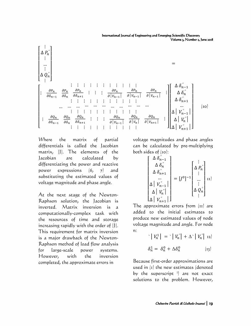
Where the matrix of partial differentials is called the Jacobian matrix, [J]. The elements of the Jacobian are calculated by differentiating the power and reactive power expressions (6, 7) and substituting the estimated values of voltage magnitude and phase angle. At the next stage of the Newton-Raphson solution, the Jacobian is inverted. Matrix inversion is a computationally-complex task with the resources of time and storage increasing rapidly with the order of [J]. This requirement for matrix inversion is a major drawback of the Newton-Raphson method of load flow analysis for large-scale power systems. However, with the inversion completed, the approximate errors in
voltage magnitudes and phase angles can be calculated by pre-multiplying both sides of (10):
!"""""""# Δ��3�°
Δ��°Δ��4�°
…Δ│�3�° │Δ│�°│
Δ│�4�° │'((((((()
= 56783�
!"""""# ⋮Δ��°⋮…⋮
Δ��°⋮ '((((()
11)
The approximate errors from (11) are added to the initial estimates to produce new estimated values of node voltage magnitude and angle. For node n: `│��│ = `│�°│+ ∆`│�°│ 12) ��� = ��7 + ∆��7 (13) Because first-order approximations are used in (1) the new estimates (denoted by the superscript ˡ) are not exact solutions to the problem. However,
Oshevire Patrick &Oshevire Patrick &Oshevire Patrick &Oshevire Patrick & Usiholo IruansiUsiholo IruansiUsiholo IruansiUsiholo Iruansi | | | | 20202020
Analysis of an Electrical Power Injection SubstationAnalysis of an Electrical Power Injection SubstationAnalysis of an Electrical Power Injection SubstationAnalysis of an Electrical Power Injection Substation
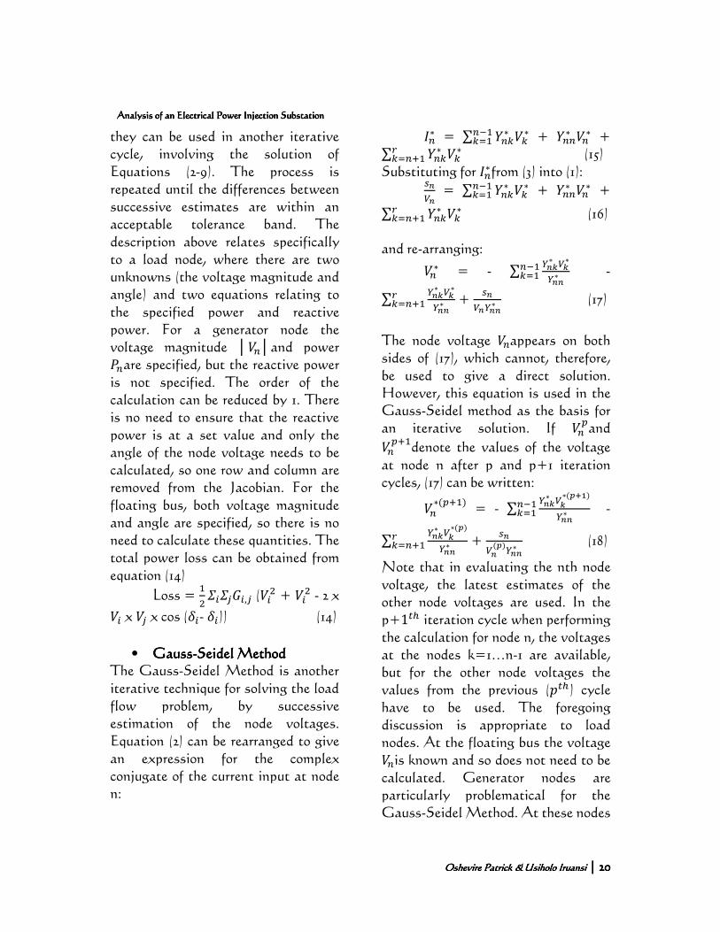
they can be used in another iterative cycle, involving the solution of Equations (2-9). The process is repeated until the differences between successive estimates are within an acceptable tolerance band. The description above relates specifically to a load node, where there are two unknowns (the voltage magnitude and angle) and two equations relating to the specified power and reactive power. For a generator node the voltage magnitude │�│and power ��are specified, but the reactive power is not specified. The order of the calculation can be reduced by 1. There is no need to ensure that the reactive power is at a set value and only the angle of the node voltage needs to be calculated, so one row and column are removed from the Jacobian. For the floating bus, both voltage magnitude and angle are specified, so there is no need to calculate these quantities. The total power loss can be obtained from equation (14)
Loss = ��9:9�;:,� (:� + :� - 2 x
: x � x cos (�:- �:)) (14)
• GaussGaussGaussGauss----Seidel MethodSeidel MethodSeidel MethodSeidel Method
The Gauss-Seidel Method is another iterative technique for solving the load flow problem, by successive estimation of the node voltages. Equation (2) can be rearranged to give an expression for the complex conjugate of the current input at node n:
��∗ = ∑ � ∗ ∗�3� �� + ��∗ �∗ + ∑ � ∗ ∗� ��4� (15) Substituting for ��∗from (3) into (1):
,1, = ∑ � ∗ ∗�3� �� + ��∗ �∗ +
∑ � ∗ ∗� ��4� (16) and re-arranging:
�∗ = - ∑ =,>∗ 1>∗=,,∗
�3� �� -
∑ =,>∗ 1>∗=,,∗
� ��4� + ,
1,=,,∗ (17)
The node voltage �appears on both sides of (17), which cannot, therefore, be used to give a direct solution. However, this equation is used in the Gauss-Seidel method as the basis for an iterative solution. If �?and
�?4�denote the values of the voltage at node n after p and p+1 iteration cycles, (17) can be written:
�∗(?4�) = - ∑ =,>∗ 1>∗(B0/)
=,,∗�3� �� -
∑ =,>∗ 1>∗(B)=,,∗
� ��4� + ,
1,(B)=,,∗ (18)
Note that in evaluating the nth node voltage, the latest estimates of the other node voltages are used. In the p+1DE iteration cycle when performing the calculation for node n, the voltages at the nodes k=1…n-1 are available, but for the other node voltages the values from the previous (FDE) cycle have to be used. The foregoing discussion is appropriate to load nodes. At the floating bus the voltage �is known and so does not need to be calculated. Generator nodes are particularly problematical for the Gauss-Seidel Method. At these nodes
Oshevire Patrick &Oshevire Patrick &Oshevire Patrick &Oshevire Patrick & Usiholo IruansiUsiholo IruansiUsiholo IruansiUsiholo Iruansi | | | | 21212121
International Journal of Engineering and Emerging Scientific DiscoveryInternational Journal of Engineering and Emerging Scientific DiscoveryInternational Journal of Engineering and Emerging Scientific DiscoveryInternational Journal of Engineering and Emerging Scientific Discovery Volume 3, Number 2,Volume 3, Number 2,Volume 3, Number 2,Volume 3, Number 2, June 2018June 2018June 2018June 2018
the power F� and voltage magnitude
│�│are specified, so in (18)
�?4�cannot be calculated because �� (the imaginary part of ��) is unknown. This difficulty is addressed by first calculating��, as follows:
The voltage component: (�∗(?4�))# =
- ∑ =,>∗ 1>∗(B0/)
=,,∗�3� �� - ∑ =,>∗ 1>∗(B)
=,,∗� ��4� +
?,1,(B)=,,∗
(19)
can be calculated immediately and substituted into (19):
�∗(?4�) = (�∗(?4�))# +
�2,1,(B)=,,∗
(20)
but, for a generator node, the
magnitude │�│is known, so considering the magnitudes in (20):
│�│² = HⱤ{(�∗(?4�))# + �2,1,(B)=,,∗
}² + Ʒ{(�∗(?4�))# + �2,1,(B)=,,∗
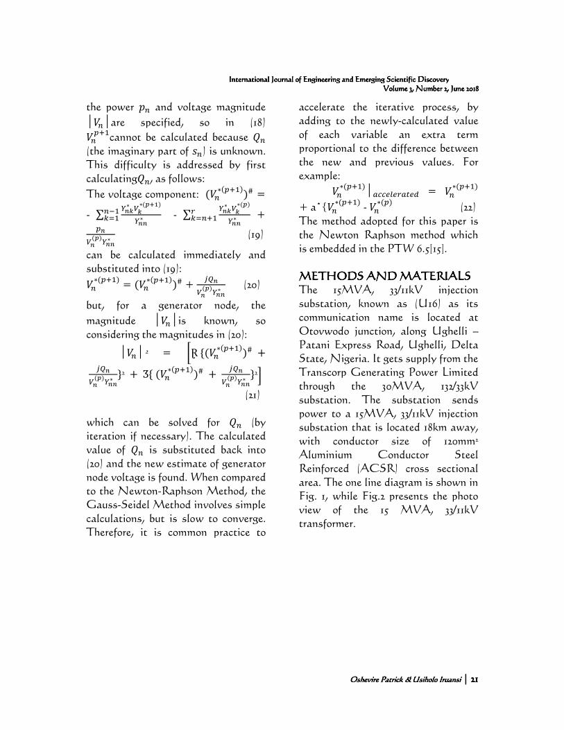
}²L (21) which can be solved for �� (by iteration if necessary). The calculated value of �� is substituted back into (20) and the new estimate of generator node voltage is found. When compared to the Newton-Raphson Method, the Gauss-Seidel Method involves simple calculations, but is slow to converge. Therefore, it is common practice to
accelerate the iterative process, by adding to the newly-calculated value of each variable an extra term proportional to the difference between the new and previous values. For example:
�∗(?4�)│MNNOPO�MDOQ = �∗(?4�)
+ a*{�∗(?4�) - �∗(?) (22)
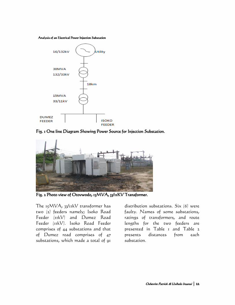
The method adopted for this paper is the Newton Raphson method which is embedded in the PTW 6.5[15]. METHODS AND MATERIALSMETHODS AND MATERIALSMETHODS AND MATERIALSMETHODS AND MATERIALS The 15MVA, 33/11kV injection substation, known as (U16) as its communication name is located at Otovwodo junction, along Ughelli – Patani Express Road, Ughelli, Delta State, Nigeria. It gets supply from the Transcorp Generating Power Limited through the 30MVA, 132/33kV substation. The substation sends power to a 15MVA, 33/11kV injection substation that is located 18km away, with conductor size of 120mm² Aluminium Conductor Steel Reinforced (ACSR) cross sectional area. The one line diagram is shown in Fig. 1, while Fig.2 presents the photo view of the 15 MVA, 33/11kV transformer.
Oshevire Patrick &Oshevire Patrick &Oshevire Patrick &Oshevire Patrick & Usiholo IruansiUsiholo IruansiUsiholo IruansiUsiholo Iruansi | | | | 22222222
Analysis of an Electrical Power Injection SubstationAnalysis of an Electrical Power Injection SubstationAnalysis of an Electrical Power Injection SubstationAnalysis of an Electrical Power Injection Substation
Fig. 1 One line Diagram Showing Power Source for Injection Substation.Fig. 1 One line Diagram Showing Power Source for Injection Substation.Fig. 1 One line Diagram Showing Power Source for Injection Substation.Fig. 1 One line Diagram Showing Power Source for Injection Substation.
Fig. Fig. Fig. Fig. 2 Photo view of Otovwodo, 15MVA, 33/11KV Transformer.2 Photo view of Otovwodo, 15MVA, 33/11KV Transformer.2 Photo view of Otovwodo, 15MVA, 33/11KV Transformer.2 Photo view of Otovwodo, 15MVA, 33/11KV Transformer.
The 15MVA, 33/11kV transformer has two (2) feeders namely; Isoko Road Feeder (11kV) and Dumez Road Feeder (11kV). Isoko Road Feeder comprises of 44 substations and that of Dumez road comprises of 47 substations, which made a total of 91
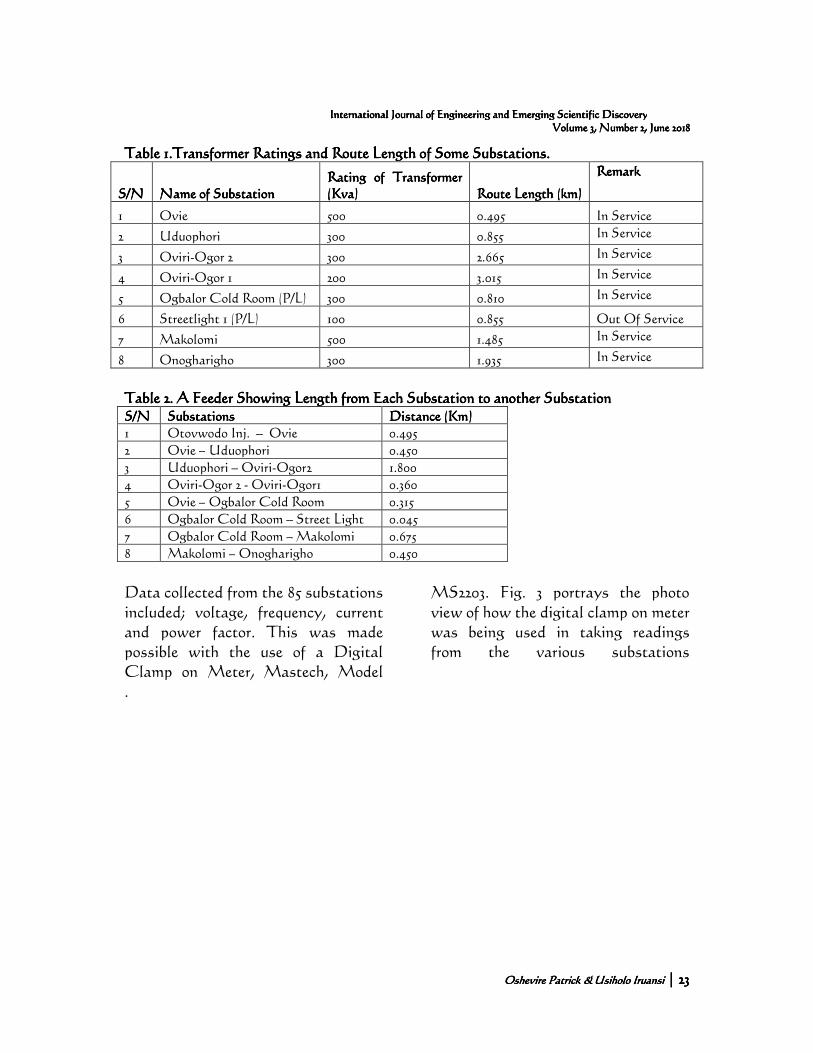
distribution substations. Six (6) were faulty. Names of some substations, ratings of transformers, and route lengths for the two feeders are presented in Table 1 and Table 2 presents distances from each substation.
Oshevire Patrick &Oshevire Patrick &Oshevire Patrick &Oshevire Patrick & Usiholo IruansiUsiholo IruansiUsiholo IruansiUsiholo Iruansi | | | | 23232323
International Journal of Engineering and Emerging Scientific DiscoveryInternational Journal of Engineering and Emerging Scientific DiscoveryInternational Journal of Engineering and Emerging Scientific DiscoveryInternational Journal of Engineering and Emerging Scientific Discovery Volume 3, Number 2,Volume 3, Number 2,Volume 3, Number 2,Volume 3, Number 2, June 2018June 2018June 2018June 2018
Table 1Table 1Table 1Table 1....Transformer Ratings and Route LengthTransformer Ratings and Route LengthTransformer Ratings and Route LengthTransformer Ratings and Route Length of Some Substationsof Some Substationsof Some Substationsof Some Substations....
S/NS/NS/NS/N Name of SubstationName of SubstationName of SubstationName of Substation Rating of Transformer Rating of Transformer Rating of Transformer Rating of Transformer (Kva)(Kva)(Kva)(Kva) Route Length (km)Route Length (km)Route Length (km)Route Length (km)
RemarkRemarkRemarkRemark
1 Ovie 500 0.495 In Service
2 Uduophori 300 0.855 In Service
3 Oviri-Ogor 2 300 2.665 In Service
4 Oviri-Ogor 1 200 3.015 In Service
5 Ogbalor Cold Room (P/L) 300 0.810 In Service
6 Streetlight 1 (P/L) 100 0.855 Out Of Service
7 Makolomi 500 1.485 In Service
8 Onogharigho 300 1.935 In Service
Table 2Table 2Table 2Table 2.... A Feeder Showing A Feeder Showing A Feeder Showing A Feeder Showing Length fromLength fromLength fromLength from Each SubstationEach SubstationEach SubstationEach Substation to to to to anotheranotheranotheranother SubstationSubstationSubstationSubstation S/NS/NS/NS/N SubstationsSubstationsSubstationsSubstations Distance (Km)Distance (Km)Distance (Km)Distance (Km)
1 Otovwodo Inj. – Ovie 0.495
2 Ovie – Uduophori 0.450
3 Uduophori – Oviri-Ogor2 1.800
4 Oviri-Ogor 2 - Oviri-Ogor1 0.360
5 Ovie – Ogbalor Cold Room 0.315
6 Ogbalor Cold Room – Street Light 0.045
7 Ogbalor Cold Room – Makolomi 0.675
8 Makolomi – Onogharigho 0.450
Data collected from the 85 substations included; voltage, frequency, current and power factor. This was made possible with the use of a Digital Clamp on Meter, Mastech, Model
MS2203. Fig. 3 portrays the photo view of how the digital clamp on meter was being used in taking readings from the various substations
.

Oshevire Patrick &Oshevire Patrick &Oshevire Patrick &Oshevire Patrick & Usiholo IruansiUsiholo IruansiUsiholo IruansiUsiholo Iruansi | | | | 24242424
Analysis of an Electrical Power Injection SubstationAnalysis of an Electrical Power Injection SubstationAnalysis of an Electrical Power Injection SubstationAnalysis of an Electrical Power Injection Substation
Fig. 3. Reading being taken from a Substation Feeder Pillar.Fig. 3. Reading being taken from a Substation Feeder Pillar.Fig. 3. Reading being taken from a Substation Feeder Pillar.Fig. 3. Reading being taken from a Substation Feeder Pillar.
Other data also collected were the route lengths from the injection substation to various distribution substations as seen in Table 2, the conductor type which was Aluminium Conductor Steel Reinforced (ACSR), from the injection substation to the various distribution substations the size was 100mm². Power tools for windows (PTW) 6.5 environment software program were used in carrying out the load flow studies. PTW 6.5 is a fully integrated suite of electrical software applications that provides intelligent power monitoring, energy management, system optimization, advanced automation, and real-time prediction. With the data (route lengths, transformer ratings, conductor (ACSR) size of existing Network, peak load readings,
off peak load readings, power factor) obtained from the field for the 85 substations they were fed into the software. The load flow was done using Newton-Raphson method which is embedded in the software. RESULTSRESULTSRESULTSRESULTS
i. The load flow analysis carried on the network shows that a total of eighty – five (85) substations in the network, voltage violation occurred in Sixty six (66) buses and Nineteen (19) buses were within the voltage acceptable limit, with voltage range between Ogele bus-0.8645 pu and Union Bank bus- 0.9560 pu. During off peak period,
Oshevire Patrick &Oshevire Patrick &Oshevire Patrick &Oshevire Patrick & Usiholo IruansiUsiholo IruansiUsiholo IruansiUsiholo Iruansi | | | | 25252525
International Journal of Engineering and Emerging Scientific DiscoveryInternational Journal of Engineering and Emerging Scientific DiscoveryInternational Journal of Engineering and Emerging Scientific DiscoveryInternational Journal of Engineering and Emerging Scientific Discovery Volume 3, Number 2,Volume 3, Number 2,Volume 3, Number 2,Volume 3, Number 2, June 2018June 2018June 2018June 2018
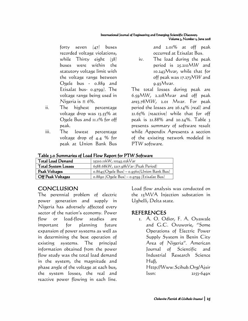
forty seven (47) buses recorded voltage violations, while Thirty eight (38) buses were within the statutory voltage limit with the voltage range between Ogele bus - 0.889 and Etisalat bus- 0.9799). The voltage range being used in Nigeria is ± 6%.
ii. The highest percentage voltage drop was 13.55% at Ogele Bus and 11.1% for off peak.
iii. The lowest percentage voltage drop of 4.4 % for peak at Union Bank Bus
and 2.01% at off peak occurred at Etisalat Bus.
iv. The load during the peak period is 25.210MW and 10.243Mvar, while that for off peak was 17.273MW and 9.93Mvar.
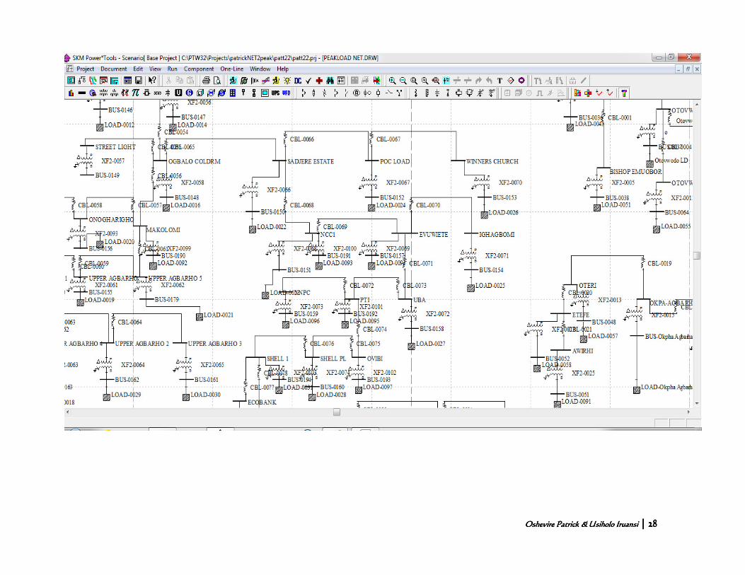
The total losses during peak are 6.59MW, 2.218Mvar and off peak are3.78MW, 2.01 Mvar. For peak period the losses are 26.14% (real) and 21.65% (reactive) while that for off peak is 21.88% and 20.24%. Table 3 presents summary of software result while Appendix Apresents a section of the existing network modeled in PTW software.
Table 3Table 3Table 3Table 3.0 Summaries o.0 Summaries o.0 Summaries o.0 Summaries of Load Flow Report for f Load Flow Report for f Load Flow Report for f Load Flow Report for PTWPTWPTWPTW SoftwareSoftwareSoftwareSoftware Total Load DemandTotal Load DemandTotal Load DemandTotal Load Demand 25210.11kW, 10243.02kVar
Total System Total System Total System Total System LossesLossesLossesLosses 6588.68kW, 2217.98kVar (Peak Period)
Peak VoltagesPeak VoltagesPeak VoltagesPeak Voltages 0.8645(Ogele Bus) – 0.9560(Union Bank Bus)
Off Peak VoltagesOff Peak VoltagesOff Peak VoltagesOff Peak Voltages 0.8890 (Ogele Bus) – 0.9799 (Etisalat Bus)
CONCLUSIONCONCLUSIONCONCLUSIONCONCLUSION The perennial problem of electric power generation and supply in Nigeria has adversely affected every sector of the nation’s economy. Power flow or load-flow studies are important for planning future expansion of power systems as well as in determining the best operation of existing systems. The principal information obtained from the power flow study was the total load demand in the system, the magnitude and phase angle of the voltage at each bus, the system losses, the real and reactive power flowing in each line.
Load flow analysis was conducted on the 15MVA Injection substation in Ughelli, Delta state. REFERENCESREFERENCESREFERENCESREFERENCES
1. A. O. Odior, F. A. Oyawale and G.C. Ovuworie, “Some Operations of Electric Power Supply System in Benin City Area of Nigeria”. American Journal of Scientific and Industrial Research Science Huβ, Http://Www.Scihub.Org/Ajsir Issn: 2153-649x
Oshevire Patrick &Oshevire Patrick &Oshevire Patrick &Oshevire Patrick & Usiholo IruansiUsiholo IruansiUsiholo IruansiUsiholo Iruansi | | | | 26262626
Analysis of an Electrical Power Injection SubstationAnalysis of an Electrical Power Injection SubstationAnalysis of an Electrical Power Injection SubstationAnalysis of an Electrical Power Injection Substation
Doi:10.5251/Ajsir.2010.1.3.636.642. 2010.
2. Musa D. A. (2007). “The Economics of Electric Power Supply in Nigeria” http://www.gamji.com/article9000/NEWS9075.htm. Visited on 7th. September, 2016.
3. Abdul Jaleel and Shabna.S.S., Load Flow Analysis and Reliability Evaluation of 220kV Kerala Power system. International Journal of Engineering and Innovative Technology (IJEIT) Volume 3, Issue 2, August 2013.
4. H. Sadaat, “Power System Analysis’ Published by McGraw-Hill publishing company limited, New Delhi, 2006.
5. Dharamjit and Tant, D.K,"Load Flow Analysis on IEEE 30 bus System", International Journal of Scientific and Research Publications, Vol. 2., November 2012.
6. O. S. Onohaebi, ˮPower System Analysisˮ M. Eng lecture notes, Department of Electrical Engineering, University of Benin, Benin-City, Edo state, Nigeria.
7. Wenping Qin, Peng Wang, Xiaoqing Han and XinhuiDu, ˮReactive Power Aspects in Reliability Assessment of Power Systemsˮ. IEEE 2011:0885-8950.2.56.
8. W. Tinney and C. Hart, “Power Flow Solution by Newton's Method”, IEEE Transactions on Power Apparatus and Systems, Vol.PAS-86, no.11, pp.1449- 1460, November. ‘1967.
9. B. Stott and O. Alsac, “Fast Decoupled Load-flow”, IEEE Transactions on Power Apparatus and Systems, Vol.PAS-93, no.3, pp.859-869, May 1974.
10. S. Tripathy, G. Prasad, O.
Malik and G. Hope, “Load-Flow Solutions for Ill- Conditioned Power Systems by a Newton-Like Method,” IEEE Transactions on Power Apparatus and Systems, Vol.PAS-101, no.10, pp.3648-3657, 1982.
11. M. E. Baran, F.F. Wu, Optimal Sizing of Capacitors Placed on a Radial Distribution System, IEEE Transactions on Power Delivery, Vol.4, no:1, pp.735-743, 1989.
Oshevire Patrick &Oshevire Patrick &Oshevire Patrick &Oshevire Patrick & Usiholo IruansiUsiholo IruansiUsiholo IruansiUsiholo Iruansi | | | | 27272727
International Journal of Engineering and Emerging Scientific DiscoveryInternational Journal of Engineering and Emerging Scientific DiscoveryInternational Journal of Engineering and Emerging Scientific DiscoveryInternational Journal of Engineering and Emerging Scientific Discovery Volume 3, Number 2,Volume 3, Number 2,Volume 3, Number 2,Volume 3, Number 2, June 2018June 2018June 2018June 2018
12. H.D Chiang, ‘A decoupled load flow method for distribution power network algorithms, analysis and convergence Study”, Electrical Power and Energy Systems, 13 (3), 130-138, 1991.
13. G.B. Jasmon, L.H.C. Lee, ˮDistribution Network Reduction for Voltage Stability Analysis and Load Flow Calculations, Electrical Power & Energy Systemsˮ, Vol.13, no:1, pp. 9-13, 1991.
14. Kumar A. and Aravindhababu, “An Improved Power Flow Technique for Distribution Systems”, Journal of Computer Science, Informatics and Electrical Engineering Vol.3, Issue 1, 2009.
15. Oshevire Patrick O.ˮ Impact of Distributed Generation (Dg) On a Typical Electrical Power Distribution Network. A Ph.D thesis submitted to the Department of Electrical and Electronics Engineering, Faculty of Engineering, University of Benin, Nigeria. 2016.
Oshevire Patrick &Oshevire Patrick &Oshevire Patrick &Oshevire Patrick & Usiholo IruansiUsiholo IruansiUsiholo IruansiUsiholo Iruansi | | | | 28282828
Analysis of an Electrical Power Injection SubstationAnalysis of an Electrical Power Injection SubstationAnalysis of an Electrical Power Injection SubstationAnalysis of an Electrical Power Injection Substation