MSC.429(98) Rev.1.pdf - International Maritime Organization
49
RESOLUTION MSC.429(98)/REV.1 (adopted on 11 November 2020) REVISED EXPLANATORY NOTES TO THE SOLAS CHAPTER II-1 SUBDIVISION AND DAMAGE STABILITY REGULATIONS
-
Upload
khangminh22 -
Category
Documents
-
view
1 -
download
0
Transcript of MSC.429(98) Rev.1.pdf - International Maritime Organization

RESOLUTION MSC.429(98)/REV.1 (adopted on 11 November 2020) REVISED EXPLANATORY NOTES TO THE SOLAS CHAPTER II-1 SUBDIVISION AND
DAMAGE STABILITY REGULATIONS

MSC 102/24/Add.1 Annex 13, page 1
MSC 102-24-Add.1.docx
ANNEX 13
RESOLUTION MSC.429(98)/Rev.1 (adopted on 11 November 2020)
REVISED EXPLANATORY NOTES TO THE SOLAS CHAPTER II-1 SUBDIVISION AND
DAMAGE STABILITY REGULATIONS
THE MARITIME SAFETY COMMITTEE, RECALLING Article 28(b) of the Convention on the International Maritime Organization concerning the function of the Committee, RECALLING ALSO that, by resolution MSC.216(82), it adopted the regulations on subdivision and damage stability as contained in SOLAS chapter II-1 which are based on the probabilistic concept, using the probability of survival after collision as a measure of ships' safety in a damaged condition, NOTING that, at the eighty-second session, it approved Interim explanatory notes to the SOLAS chapter II-1 subdivision and damage stability regulations (MSC.1/Circ.1226), to assist Administrations in the uniform interpretation and application of the aforementioned subdivision and damage stability regulations, NOTING ALSO that, at the eighty-fifth session, it adopted the Explanatory notes to the SOLAS chapter II-1 subdivision and damage stability regulations (resolution MSC.281(85)), NOTING FURTHER that, by resolution MSC.421(98), it adopted amendments to regulations on subdivision and damage stability, as contained in SOLAS chapter II-1, RECOGNIZING that the Revised Explanatory Notes should be adopted in conjunction with the adoption of the aforementioned amendments to subdivision and damage stability regulations (resolution MSC.421(98)), RECOGNIZING ALSO that the appropriate application of the Revised Explanatory Notes is essential for ensuring the uniform application of the SOLAS chapter II-1 subdivision and damage stability regulations, RECALLING that, having considered, at its ninety-eighth session (7 to 16 June 2017), the recommendations made by the Sub-Committee on Ship Design and Construction at its fourth session, it adopted, by resolution MSC.429(98), the Revised explanatory notes to the SOLAS chapter II-1 subdivision and damage stability regulations, HAVING CONSIDERED, at its 102nd session, minor amendments to paragraph 4 of the Explanatory Note to SOLAS regulation 17 (Internal watertight integrity of passenger ships above the bulkhead deck), 1 ADOPTS the Revised explanatory notes to the SOLAS chapter II-1 subdivision and damage stability regulations set out in the annex to the present resolution; 2 URGES Contracting Governments and all parties concerned to utilize the Revised Explanatory Notes when applying the SOLAS chapter II-1 subdivision and damage stability regulations adopted by resolution MSC.216(82), as amended;
RESOLUTION MSC.429(98)/REV.1 (adopted on 11 November 2020) REVISED EXPLANATORY NOTES TO THE SOLAS CHAPTER II-1 SUBDIVISION AND
DAMAGE STABILITY REGULATIONS

MSC 102/24/Add.1 Annex 13, page 2
MSC 102-24-Add.1.docx
3 INVITES Contracting Governments to note that these Revised Explanatory Notes take effect on ships as defined in SOLAS regulation II-1/1.1.1, as adopted by resolution MSC.421(98). 4 REVOKES resolution MSC.429(98).
***
RESOLUTION MSC.429(98)/REV.1 (adopted on 11 November 2020) REVISED EXPLANATORY NOTES TO THE SOLAS CHAPTER II-1 SUBDIVISION AND
DAMAGE STABILITY REGULATIONS

MSC 102/24/Add.1 Annex 13, page 3
MSC 102-24-Add.1.docx
ANNEX
REVISED EXPLANATORY NOTES TO THE SOLAS CHAPTER II-1 SUBDIVISION AND
DAMAGE STABILITY REGULATIONS
Contents
Part A – INTRODUCTION
Part B – GUIDANCE ON INDIVIDUAL SOLAS CHAPTER II-1 SUBDIVISION AND DAMAGE STABILITY REGULATIONS
Regulation 1 Application
Regulation 2 Definitions
Regulation 4 General
Regulation 5 Intact stability
Regulation 5-1 Stability information to be supplied to the master
Regulation 6 Required subdivision index R
Regulation 7 Attained subdivision index A
Regulation 7-1 Calculation of the factor pi
Regulation 7-2 Calculation of the factor si
Regulation 7-3 Permeability
Regulation 8 Special requirements concerning passenger ship stability
Regulation 8-1 System capabilities and operational information after a flooding
casualty on passenger ships
Regulation 9 Double bottoms in passenger ships and cargo ships other than
tankers
Regulation 10 Construction of watertight bulkheads
Regulation 12 Peak and machinery space bulkheads, shaft tunnels, etc.
Regulation 13 Openings in watertight bulkheads below the bulkhead deck in
passenger ships
Regulation 13-1 Openings in watertight bulkheads and internal decks in cargo ships
Regulation 15 Openings in the shell plating below the bulkhead deck of passenger
ships and the freeboard deck of cargo ships
Regulation 15-1 External openings in cargo ships
Regulation 16 Construction and initial tests of watertight closures
Regulation 17 Internal watertight integrity of passenger ships above the bulkhead
deck
Regulation 22
Prevention and control of water ingress, etc.
Appendix
Guidelines for the preparation of subdivision and damage stability
calculations
RESOLUTION MSC.429(98)/REV.1 (adopted on 11 November 2020) REVISED EXPLANATORY NOTES TO THE SOLAS CHAPTER II-1 SUBDIVISION AND
DAMAGE STABILITY REGULATIONS

MSC 102/24/Add.1 Annex 13, page 4
MSC 102-24-Add.1.docx
PART A
INTRODUCTION
1 The harmonized SOLAS regulations on subdivision and damage stability, as contained in SOLAS chapter II-1, are based on a probabilistic concept which uses the probability of survival after collision as a measure of ships' safety in a damaged condition. This probability is referred to as the "attained subdivision index A" in the regulations. It can be considered an objective measure of ships' safety and, ideally, there would be no need to supplement this index by any deterministic requirements.
2 The philosophy behind the probabilistic concept is that two different ships with the same attained index are of equal safety and, therefore, there is no need for special treatment of specific parts of the ship, even if they are able to survive different damages. The only areas which are given special attention in the regulations are the forward and bottom regions, which are dealt with by special subdivision rules provided for cases of ramming and grounding.
3 Only a few deterministic elements, which were necessary to make the concept practicable, have been included. It was also necessary to include a deterministic "minor damage" on top of the probabilistic regulations for passenger ships to avoid ships being designed with what might be perceived as unacceptably vulnerable spots in some part of their length.
4 It is easily recognized that there are many factors that will affect the final consequences of hull damage to a ship. These factors are random and their influence is different for ships with different characteristics. For example, it would seem obvious that in ships of similar size carrying different amounts of cargo, damages of similar extents may lead to different results because of differences in the range of permeability and draught during service. The mass and velocity of the ramming ship is obviously another random variable.
5 Owing to this, the effect of a three-dimensional damage to a ship with given watertight
subdivision depends on the following circumstances:
.1
which particular space or group of adjacent spaces is flooded;
.2
the draught, trim and intact metacentric height at the time of damage;
.3
the permeability of affected spaces at the time of damage;
.4
the sea state at the time of damage; and
.5 other factors such as possible heeling moments owing to unsymmetrical
weights.
6 Some of these circumstances are interdependent and the relationship between them and their effects may vary in different cases. Additionally, the effect of hull strength on penetration will obviously have some effect on the results for a given ship. Since the location and size of the damage is random, it is not possible to state which part of the ship becomes flooded. However, the probability of flooding a given space can be determined if the probability of occurrence of certain damages is known from experience, that is, damage statistics. The probability of flooding a space is then equal to the probability of occurrence of all such damages which just open the considered space to the sea.
RESOLUTION MSC.429(98)/REV.1 (adopted on 11 November 2020) REVISED EXPLANATORY NOTES TO THE SOLAS CHAPTER II-1 SUBDIVISION AND
DAMAGE STABILITY REGULATIONS

MSC 102/24/Add.1 Annex 13, page 5
MSC 102-24-Add.1.docx
7 For these reasons and because of mathematical complexity as well as insufficient
data, it would not be practicable to make an exact or direct assessment of their effect on the
probability that a particular ship will survive a random damage if it occurs. However, accepting
some approximations or qualitative judgments, a logical treatment may be achieved by using
the probability approach as the basis for a comparative method for the assessment and
regulation of ship safety.
8 It may be demonstrated by means of probability theory that the probability of ship
survival should be calculated as the sum of probabilities of its survival after flooding each single
compartment, each group of two, three, etc., adjacent compartments multiplied, respectively,
by the probabilities of occurrence of such damages leading to the flooding of the corresponding
compartment or group of compartments.
9 If the probability of occurrence for each of the damage scenarios the ship could be
subjected to is calculated and then combined with the probability of surviving each of these
damages with the ship loaded in the most probable loading conditions, the attained index A as
a measure for the ship's ability to sustain a collision damage can be determined.
10 It follows that the probability that a ship will remain afloat without sinking or capsizing
as a result of an arbitrary collision in a given longitudinal position can be broken down to:
.1
the probability that the longitudinal centre of damage occurs in just the region
of the ship under consideration;
.2
the probability that this damage has a longitudinal extent that only includes
spaces between the transverse watertight bulkheads found in this region;
.3
the probability that the damage has a vertical extent that will flood only the
spaces below a given horizontal boundary, such as a watertight deck;
.4
the probability that the damage has a transverse penetration not greater than
the distance to a given longitudinal boundary; and
.5 the probability that the watertight integrity and the stability throughout the
flooding sequence is sufficient to avoid capsizing or sinking.
11 The first three of these factors are solely dependent on the watertight arrangement of
the ship, while the last two depend on the ship's shape. The last factor also depends on the
actual loading condition. By grouping these probabilities, calculations of the probability of
survival, or attained index A, have been formulated to include the following probabilities:
.1
the probability of flooding each single compartment and each possible group
of two or more adjacent compartments; and
.2 the probability that the stability after flooding a compartment or a group of two or more adjacent compartments will be sufficient to prevent capsizing or dangerous heeling due to loss of stability or to heeling moments in intermediate or final stages of flooding.
12 This concept allows a rule requirement to be applied by requiring a minimum value of
A for a particular ship. This minimum value is referred to as the "required subdivision index R"
in the present regulations and can be made dependent on ship size, number of passengers or
other factors legislators might consider important.
RESOLUTION MSC.429(98)/REV.1 (adopted on 11 November 2020) REVISED EXPLANATORY NOTES TO THE SOLAS CHAPTER II-1 SUBDIVISION AND
DAMAGE STABILITY REGULATIONS

MSC 102/24/Add.1 Annex 13, page 6
MSC 102-24-Add.1.docx
13 Evidence of compliance with the rules then simply becomes: A ≥ R 13.1 As explained above, the attained subdivision index A is determined by a formula for the entire probability as the sum of the products for each compartment or group of compartments of the probability that a space is flooded, multiplied by the probability that the ship will not capsize or sink due to flooding of the considered space. In other words, the general formula for the attained index can be given in the form:
A = pisi 13.2 Subscript "i" represents the damage zone (group of compartments) under consideration within the watertight subdivision of the ship. The subdivision is viewed in the longitudinal direction, starting with the aftmost zone/compartment.
13.3 The value of "pi" represents the probability that only the zone "i" under consideration
will be flooded, disregarding any horizontal subdivision, but taking transverse subdivision into
account. Longitudinal subdivision within the zone will result in additional flooding scenarios,
each with its own probability of occurrence.
13.4 The value of "si" represents the probability of survival after flooding the zone "i" under
consideration.
14 Although the ideas outlined above are very simple, their practical application in an
exact manner would give rise to several difficulties if a mathematically perfect method were to
be developed. As pointed out above, an extensive but still incomplete description of the
damage will include its longitudinal and vertical location as well as its longitudinal, vertical and
transverse extent. Apart from the difficulties in handling such a five-dimensional random
variable, it is impossible to determine its probability distribution very accurately with the
presently available damage statistics. Similar limitations are true for the variables and physical
relationships involved in the calculation of the probability that a ship will not capsize or sink
during intermediate stages or in the final stage of flooding.
15 A close approximation of the available statistics would result in extremely numerous
and complicated computations. In order to make the concept practicable, extensive
simplifications are necessary. Although it is not possible to calculate the exact probability of
survival on such a simplified basis, it has still been possible to develop a useful comparative
measure of the merits of the longitudinal, transverse and horizontal subdivision of a ship.
RESOLUTION MSC.429(98)/REV.1 (adopted on 11 November 2020) REVISED EXPLANATORY NOTES TO THE SOLAS CHAPTER II-1 SUBDIVISION AND
DAMAGE STABILITY REGULATIONS

MSC 102/24/Add.1 Annex 13, page 7
MSC 102-24-Add.1.docx
PART B
GUIDANCE ON INDIVIDUAL SOLAS CHAPTER II-1
SUBDIVISION AND DAMAGE STABILITY REGULATIONS
REGULATION 1 – APPLICATION
Regulation 1.3
1 If a passenger ship built before 1 January 2009 undergoes alterations or modifications of major character, it may still remain under the damage stability regulations applicable to ships built before 1 January 2009.
2 If a passenger ship constructed on or after 1 January 2009 but before the applicable dates in regulation 1.1.1.11 undergoes alterations or modifications of major character that do not impact the watertight subdivision of the ship, or only have a minor impact, it may still remain under the damage stability regulations that were applicable when it was constructed. However, if alterations or modifications of major character significantly impact the watertight subdivision of the ship, it should comply with the damage stability regulations in part B-1 applicable when the alterations or modifications of major character are carried out unless the Administration determines that this is not reasonable and practicable, in which case the attained subdivision index A should be raised above the original construction required subdivision index R as much as practical.
3 Application of MSC.1/Circ.1246 is limited to cargo ships constructed before 1 January 2009.
4 A cargo ship constructed on or after 1 January 2009 of less than 80 m in length that is later lengthened beyond that limit should fully comply with the damage stability regulations according to its type and length.
5 If a passenger ship that has been in domestic service only and never been issued a SOLAS Passenger Ship Safety Certificate is converted to international service, for purposes of the stability requirements in parts B, B-1, B-2, B-3 and B-4 it should be treated as a passenger ship constructed on the date on which such a conversion commences.
REGULATION 2 – DEFINITIONS Regulation 2.1 Subdivision length (Ls) – Different examples of Ls showing the buoyant hull and the reserve buoyancy are provided in the figures below. The limiting deck for the reserve buoyancy may be partially watertight. The maximum possible vertical extent of damage above the baseline is ds + 12.5 metres.
1 References to regulations in this Guidance are to regulations of SOLAS chapter II-1, unless expressly
provided otherwise.
RESOLUTION MSC.429(98)/REV.1 (adopted on 11 November 2020) REVISED EXPLANATORY NOTES TO THE SOLAS CHAPTER II-1 SUBDIVISION AND
DAMAGE STABILITY REGULATIONS

MSC 102/24/Add.1 Annex 13, page 8
MSC 102-24-Add.1.docx
Regulation 2.6
Freeboard deck – See explanatory notes for regulation 13-1 for the treatment of a stepped freeboard deck with regard to watertightness and construction requirements.
RESOLUTION MSC.429(98)/REV.1 (adopted on 11 November 2020) REVISED EXPLANATORY NOTES TO THE SOLAS CHAPTER II-1 SUBDIVISION AND
DAMAGE STABILITY REGULATIONS
Subdivisio, Le rgth '-s
Subdivisicri Lergth '-s
ds+12.5m
ds
rds +1 2 5m
I I ds --¼'77'7"7''7"7'Y,.,,Y.,,7'7'7'7''7-¥'7-¥7¥'7¥'7¥,¥,¥,¥,¥-,¥-,¥.¥,,¥-,,¥-,,¥-,,"{;;.....-:'f-
/// // ///// // //// // ///// / ///// // / //// / ////// / ///// / ////// / ///// // // //// / //////////// / ///////////////
Sub divisicn Le rgth '-s ["l"'"✓';J k~.LI Bu0yanthull ~?] Rese-ve bJoyaicy fA R Reserve buoyancy, not subJec:t
t!J u to dama;ie
__ i..._, lo _____________ ...,

MSC 102/24/Add.1 Annex 13, page 9
MSC 102-24-Add.1.docx
Regulation 2.11
Light service draught (dl) – The light service draught (dl) corresponds, in general, to the ballast arrival condition with 10% consumables for cargo ships. For passenger ships it corresponds, in general, to the arrival condition with 10% consumables, a full complement of passengers and crew and their effects, and ballast as necessary for stability and trim. Any temporary ballast water exchange conditions for compliance with the International Convention for the Control and Management of Ships' Ballast Water and Sediments, 2004 or any non-service conditions, such as dry-docking, should not be taken as dl.
Regulation 2.19
Bulkhead deck – See explanatory notes for regulation 13 for the treatment of a stepped bulkhead deck with regard to watertightness and construction requirements.
REGULATION 4 – GENERAL
Regulation 4.5
See explanatory notes for regulation 7-2.2, for information and guidance related to these provisions.
REGULATION 5 – INTACT STABILITY
Regulation 5.2
1 For the purpose of this regulation, a sister ship means a cargo ship built by the same
shipyard from the same plans.
2 For any new sister ship with known differences from the lead sister ship that do not exceed the lightship displacement and longitudinal centre of gravity deviation limits specified in regulation 5.2, a detailed weights and centres of gravity calculation to adjust the lead sister ship's lightship properties should be carried out. These adjusted lead sister ship lightship properties are then used for comparison to the new sister ship's lightweight survey results. However, in cases when the known differences from the lead sister ship exceed lightship displacement or longitudinal centre of gravity deviation limits specified in regulation 5.2, the ship should be inclined.
3 When the lightweight survey results do not exceed the specified deviation limits, the lightship displacement and the longitudinal and transverse centres of gravity obtained from the lightweight survey should be used in conjunction with the higher of either the lead sister ship's vertical centre of gravity or the calculated, adjusted value.
4 Regulation 5.2 may be applied to the SPS Code ships certified to carry less
than 240 persons.
Regulation 5.4
1 When alterations are made to a ship in service that result in calculable differences in the lightship properties, a detailed weights and centres of gravity calculation to adjust the lightship properties should be carried out. If the adjusted lightship displacement or longitudinal centre of gravity, when compared to the approved values, exceeds one of the deviation limits specified in regulation 5.5, the ship should be re-inclined. In addition, if the adjusted lightship vertical centre of gravity, when compared to the approved value, exceeds 1%, the ship should be re-inclined. The lightship transverse centre of gravity is not subject to a deviation limit.
RESOLUTION MSC.429(98)/REV.1 (adopted on 11 November 2020) REVISED EXPLANATORY NOTES TO THE SOLAS CHAPTER II-1 SUBDIVISION AND
DAMAGE STABILITY REGULATIONS

MSC 102/24/Add.1 Annex 13, page 10
MSC 102-24-Add.1.docx
2 When a ship does not exceed the deviation limits specified in explanatory note 1 above, amended stability information should be provided to the master using the new calculated lightship properties if any of the following deviations from the approved values are exceeded:
.1
1% of the lightship displacement; or
.2
0.5% of L for the longitudinal centre of gravity; or
.3 0.5% of the vertical centre of gravity.
2.1 However, in cases when these deviation limits are not exceeded, it is not necessary to amend the stability information supplied to the master.
3 When multiple alterations are made to a ship in service over a period of time and each alteration is within the deviation limits specified above, the cumulative total changes to the lightship properties from the most recent inclining also should not exceed the deviation limits specified above or the ship should be re-inclined.
Regulation 5.5
When the lightweight survey results do not exceed the specified deviation limits, the lightship displacement and the longitudinal and transverse centres of gravity obtained from the lightweight survey should be used in conjunction with the vertical centre of gravity derived from the most recent inclining in all subsequent stability information supplied to the master.
REGULATION 5-1 – STABILITY INFORMATION TO BE SUPPLIED TO THE MASTER
Regulation 5-1.3
The requirement that applied trim values shall coincide in all stability information intended for use on board is intended to address initial stability calculations as well as those that may be necessary during the service life of the ship.
Regulation 5-1.4 (see also regulation 7.2)
1 Linear interpolation of the limiting values between the draughts ds, dp and dl is only
applicable to minimum GM values. If it is intended to develop curves of maximum permissible
KG, a sufficient number of KMT values for intermediate draughts should be calculated to ensure
that the resulting maximum KG curves correspond with a linear variation of GM. When light
service draught is not with the same trim as other draughts, KMT for draughts between partial
and light service draught should be calculated for trims interpolated between trim at partial
draught and trim at light service draught.
2 In cases where the operational trim range is intended to exceed ±0.5% of L, the
original GM limit line should be designed in the usual manner with the deepest subdivision
draught and partial subdivision draught calculated at level trim and estimated service trim used
for the light service draught. Then additional sets of GM limit lines should be constructed on
the basis of the operational range of trims which is covered by loading conditions for each of
the three draughts ds, dp and dl ensuring that intervals of 1% L are not exceeded. The sets of
GM limit lines are combined to give a single envelope limiting GM curve. The effective trim
range of the curve should be clearly stated.
RESOLUTION MSC.429(98)/REV.1 (adopted on 11 November 2020) REVISED EXPLANATORY NOTES TO THE SOLAS CHAPTER II-1 SUBDIVISION AND
DAMAGE STABILITY REGULATIONS

MSC 102/24/Add.1 Annex 13, page 11
MSC 102-24-Add.1.docx
3 If multiple GM limiting curves are obtained from damage stability calculations of
differing trims in accordance with regulation 7, an envelope curve covering all calculated trim
values should be developed. Calculations covering different trim values should be carried out
in steps not exceeding 1% of L. The whole range including intermediate trims should be
covered by the damage stability calculations. Refer to the example showing an envelope curve
obtained from calculations of 0 trim and 1% of L.
4 Temporary loading conditions may occur with a draught less than the light service
draught dl due to ballast water exchange requirements, etc. In these cases, for draughts below
dl, the GM limit value at dl is to be used.
5 Ships may be permitted to sail at draughts above the deepest subdivision draught ds
according to the International Convention on Load Lines, e.g. using the tropical freeboard. In
these cases, for draughts above ds the GM limit value at ds is to be used.
Regulation 5-1.5
There could be cases where it is desirable to expand the trim range, for instance around dp. This approach is based on the principle that it is not necessary that the same number of trims be used when the GM is the same throughout a draught and when the steps between trims do not exceed 1% of L. In these cases there will be three A values based on draughts s1, p1, l1 and s2, p2, l2 and s2, p3, l2. The lowest value of each partial index As, Ap and Al across these trims should be used in the summation of the attained subdivision index A.
Trim limit diagram GM limit curve
Regulation 5-1.6
This provision is intended to address cases where an Administration approves an alternative means of verification.
l 1
p 2 p 3
l 2
s 1 s 2
p 1
Draug
ht
Trim %L 0.5 0.5 %L 0.5 %L %L 0.5
Draug
ht
GM
Permitted Permitted d p
d s
d l
RESOLUTION MSC.429(98)/REV.1 (adopted on 11 November 2020) REVISED EXPLANATORY NOTES TO THE SOLAS CHAPTER II-1 SUBDIVISION AND
DAMAGE STABILITY REGULATIONS
~ ' -•
d, dp Draught
- -j;jl- - - -/,, I
,, ,, I ,, I
- -q- - - - -jZ}- - - - -
I / / I / /
' I / \ I / I / /
/ I
Trim = 0
Trim = 1% L aft
Enve lope curve covering trim ranges from O .5% L forward tQ. 1.5% L aft

MSC 102/24/Add.1 Annex 13, page 12
MSC 102-24-Add.1.docx
REGULATION 6 – REQUIRED SUBDIVISION INDEX R Regulation 6.1
To demonstrate compliance with these provisions, see the Guidelines for the preparation of subdivision and damage stability calculations, set out in the appendix, regarding the presentation of damage stability calculation results.
REGULATION 7 – ATTAINED SUBDIVISION INDEX A Regulation 7.1
1 The probability of surviving after collision damage to the ship's hull is expressed by
the index A. Producing an index A requires calculation of various damage scenarios defined
by the extent of damage and the initial loading conditions of the ship before damage.
Three loading conditions should be considered and the result weighted as follows:
lps AAAA 2.04.04.0 ++=
where the indices s, p and l represent the three loading conditions and the factor to be multiplied to the index indicates how the index A from each loading condition is weighted.
2 The method of calculating A for a loading condition is expressed by the formula:
2.1 The index c represents one of the three loading conditions, the index i represents
each investigated damage or group of damages and t is the number of damages to be
investigated to calculate Ac for the particular loading condition.
2.2 To obtain a maximum index A for a given subdivision, t has to be equal to T, the total
number of damages.
3 In practice, the damage combinations to be considered are limited either by
significantly reduced contributions to A (i.e. flooding of substantially larger volumes) or by
exceeding the maximum possible damage length.
4 The index A is divided into partial factors as follows:
pi The p factor is solely dependent on the geometry of the watertight arrangement of the ship.
vi The v factor is dependent on the geometry of the watertight arrangement (decks) of the ship and the draught of the initial loading condition. It represents the probability that the spaces above the horizontal subdivision will not be flooded.
si The s factor is dependent on the calculated survivability of the ship after the considered damage for a specific initial condition.
𝐴𝑐 = 𝑝𝑖 𝑣𝑖𝑠𝑖
𝑖=𝑡
𝑖=1
RESOLUTION MSC.429(98)/REV.1 (adopted on 11 November 2020) REVISED EXPLANATORY NOTES TO THE SOLAS CHAPTER II-1 SUBDIVISION AND
DAMAGE STABILITY REGULATIONS

MSC 102/24/Add.1 Annex 13, page 13
MSC 102-24-Add.1.docx
5 Three initial loading conditions should be used for calculating each index A. The
loading conditions are defined by their mean draught d, trim and GM (or KG). The mean
draught and trim are illustrated in the figure below.
6 The GM (or KG) values for the three loading conditions could, as a first attempt, be
taken from the intact stability GM (or KG) limit curve. If the required index R is not obtained,
the GM (or KG) values may be increased (or reduced), implying that the intact loading
conditions from the intact stability book must now meet the GM (or KG) limit curve from the
damage stability calculations derived by linear interpolation between the three GMs.
7 For a series of new passenger or cargo ships built from the same plans each of which
have the same draughts ds, dp and dl as well as the same GM and trim limits, the attained
subdivision index A calculated for the lead ship may be used for the other ships. In addition,
small differences in the draught dl (and the subsequent change in the draught dp) are
acceptable if they are due to small differences in the lightship characteristics that do not exceed
the deviation limits specified in regulation 5.2. For cases where these conditions are not met,
a new attained subdivision index A should be calculated.
"Built from the same plans" means that the watertight and weathertight aspects of the hull, bulkheads, openings and other parts of a ship that impact the attained subdivision index A calculation remain exactly the same.
8 For a passenger or cargo ship in service which undergoes alterations that materially
affect the stability information supplied to the master and require it to be re-inclined in
accordance with regulation 5.4, a new attained subdivision index A should be calculated.
However, for alteration cases where a re-inclining is not required and the alterations do not
change the watertight and weathertight arrangements of the ship that impact the attained
subdivision index A, if ds and the GM and trim limits remain the same then a new attained
subdivision index A is not required.
9 For passenger ships subject to lightweight surveys every 5 years, if the lightweight
survey results are within the limits specified in regulation 5.5, and ds and the GM and trim limits
remain the same, a new attained subdivision index A is not required. However, if the lightweight
survey results exceed either limit specified in regulation 5.5, a new attained subdivision index
A should be calculated.
10 For any new passenger or cargo ship for which the deviation in lightship
characteristics between the preliminary and the as built values are within the limits specified in
regulation 5.2 and ds is unchanged, then the preliminary attained subdivision index A
calculation may be approved as the final attained subdivision index A calculation. However,
for cases where these conditions are not met, then a new attained subdivision index A should
be calculated.
Regulation 7.2
When additional calculations of A are performed for different trims, for a given set of calculations the difference between trim values for ds, dp and dl may not exceed 1% L.
60 %
Level trim Level trim Service trim
Mean draught d % 100
d l
d p d s
RESOLUTION MSC.429(98)/REV.1 (adopted on 11 November 2020) REVISED EXPLANATORY NOTES TO THE SOLAS CHAPTER II-1 SUBDIVISION AND
DAMAGE STABILITY REGULATIONS
l I F I ~ /
I ; ___ ;z-__ _

MSC 102/24/Add.1 Annex 13, page 14
MSC 102-24-Add.1.docx
Regulation 7.5
1 With the same intent as wing tanks, the summation of the attained index A should
reflect effects caused by all watertight bulkheads and flooding boundaries within the damaged
zone. It is not correct to assume damage only to one half of the ship's breadth B and ignore
changes in subdivision that would reflect lesser contributions.
2 In the forward and aft ends of the ship where the sectional breadth is less than the
ship's breadth B, transverse damage penetration can extend beyond the centreline bulkhead.
This application of the transverse extent of damage is consistent with the methodology to
account for the localized statistics which are normalized on the greatest moulded breadth B
rather than the local breadth.
3 Where, at the extreme ends of the ship, the subdivision exceeds the waterline at the
deepest subdivision draught, the damage penetration b or B/2 is to be taken from centreline.
The figure below illustrates the shape of the B/2 line.
4 Where longitudinal corrugated bulkheads are fitted in wing compartments or on the
centreline, they may be treated as equivalent plane bulkheads provided the corrugation depth
is of the same order as the stiffening structure. The same principle may also be applied to
transverse corrugated bulkheads.
RESOLUTION MSC.429(98)/REV.1 (adopted on 11 November 2020) REVISED EXPLANATORY NOTES TO THE SOLAS CHAPTER II-1 SUBDIVISION AND
DAMAGE STABILITY REGULATIONS
Deepest Subdivision Waterline
Damage penetration b
Maximum damage penetration B/2
B/2 Line

MSC 102/24/Add.1 Annex 13, page 15
MSC 102-24-Add.1.docx
Regulation 7.6
Refer to the explanatory notes for regulation 7-2.2 for the treatment of free surfaces during all stages of flooding.
Regulation 7.7
1 Pipes and valves directly adjacent or situated as close as practicable to a bulkhead
or to a deck can be considered to be part of the bulkhead or deck, provided the separation
distance on either side of the bulkhead or deck is of the same order as the bulkhead or deck
stiffening structure. The same applies for small recesses, drain wells, etc.
2 For ships up to L = 150 m the provision for allowing "minor progressive flooding"
should be limited to pipes penetrating a watertight subdivision with a total cross-sectional area
of not more than 710 mm2 between any two watertight compartments. For ships of L = 150 m
and upwards the total cross-sectional area of pipes should not exceed the cross-sectional area
of one pipe with a diameter of L/5000 m.
REGULATION 7-1 – CALCULATION OF THE FACTOR pi
General
1 The definitions below are intended to be used for the application of part B-1 only.
2 In regulation 7-1, the words "compartment" and "group of compartments" should be
understood to mean "zone" and "adjacent zones".
3 Zone – a longitudinal interval of the ship within the subdivision length.
4 Room – a part of the ship, limited by bulkheads and decks, having a specific
permeability.
5 Space – a combination of rooms.
6 Compartment – a space within watertight boundaries.
7 Damage – the three-dimensional extent of the breach in the ship.
8 For the calculation of p, v, r and b only the damage should be considered, for the
calculation of the s-value the flooded space should be considered. The figures below
illustrate the difference.
Damage shown as the bold square: Flooded space shown below:
RESOLUTION MSC.429(98)/REV.1 (adopted on 11 November 2020) REVISED EXPLANATORY NOTES TO THE SOLAS CHAPTER II-1 SUBDIVISION AND
DAMAGE STABILITY REGULATIONS
-EJ
MSC 102/24/Add.1 Annex 13, page 16
MSC 102-24-Add.1.docx
Regulation 7-1.1.1
1 The coefficients b11, b12, b21 and b22 are coefficients in the bi-linear probability density function on normalized damage length (J). The coefficient b12 is dependent on whether Ls is greater or less than L* (i.e. 260 m); the other coefficients are valid irrespective of Ls.
1. Longitudinal subdivision
2 In order to prepare for the calculation of index A, the ship's subdivision length Ls is
divided into a fixed discrete number of damage zones. These damage zones will determine
the damage stability investigation in the way of specific damages to be calculated.
3 There are no specific rules for longitudinally subdividing the ship, except that the
length Ls defines the extremities of the zones. Zone boundaries need not coincide with physical
watertight boundaries. However, it is important to consider a strategy carefully to obtain a good
result (that is a large attained index A). All zones and combination of adjacent zones may
contribute to the index A. In general it is expected that the more zone boundaries the ship is
divided into the higher the attained index will be, but this benefit should be balanced against
extra computing time. The figure below shows different longitudinal zone divisions of the length
Ls.
4 The first example is a very rough division into three zones of approximately the same size with limits where longitudinal subdivision is established. The probability that the ship will survive a damage in one of the three zones is expected to be low (i.e. the s-factor is low or zero) and, therefore, the total attained index A will be correspondingly low.
5 In the second example the zones have been placed in accordance with the watertight
arrangement, including minor subdivision (as in double bottom, etc.). In this case there is a
much better chance of obtaining higher s-factors.
6 Where transverse corrugated bulkheads are fitted, they may be treated as equivalent plane bulkheads, provided the corrugation depth is of the same order as the stiffening structure.
7 Pipes and valves directly adjacent or situated as close as practicable to a transverse
bulkhead can be considered to be part of the bulkhead, provided the separation distance on
either side of the bulkhead is of the same order as the bulkhead stiffening structure. The same
applies for small recesses, drain wells, etc.
RESOLUTION MSC.429(98)/REV.1 (adopted on 11 November 2020) REVISED EXPLANATORY NOTES TO THE SOLAS CHAPTER II-1 SUBDIVISION AND
DAMAGE STABILITY REGULATIONS
L\ 1--------+-I ----.-------+----------+------d 5 2 1 Z2 23
◄--1>!<11---1,◄ --◄--OS◄ _ ____ .,.,...._.,._,,... __ _ z, ' Z2 ' Z3 Z◄ ZS ' Z6 za Z9 ' ZIO Z11

MSC 102/24/Add.1 Annex 13, page 17
MSC 102-24-Add.1.docx
8 For cases where the pipes and valves cannot be considered as being part of the transverse bulkhead, when they present a risk of progressive flooding to other watertight compartments that will have influence on the overall attained index A, they should be handled either by introducing a new damage zone and accounting for the progressive flooding to associated compartments or by introducing a gap.
9 The triangle in the figure below illustrates the possible single and multiple zone damages in a ship with a watertight arrangement suitable for a seven-zone division. The triangles at the bottom line indicate single zone damages and the parallelograms indicate adjacent zones damages.
10 As an example, the triangle illustrates a damage opening the rooms in zone 2 to the
sea and the parallelogram illustrates a damage where rooms in zones 4, 5 and 6 are flooded
simultaneously.
11 The shaded area illustrates the effect of the maximum absolute damage length. The
p-factor for a combination of three or more adjacent zones equals zero if the length of the
combined adjacent damage zones minus the length of the foremost and the aft most damage
zones in the combined damage zone is greater than the maximum damage length. Having this
in mind when subdividing Ls could limit the number of zones defined to maximize the attained
index A.
RESOLUTION MSC.429(98)/REV.1 (adopted on 11 November 2020) REVISED EXPLANATORY NOTES TO THE SOLAS CHAPTER II-1 SUBDIVISION AND
DAMAGE STABILITY REGULATIONS
z, ZI

MSC 102/24/Add.1 Annex 13, page 18
MSC 102-24-Add.1.docx
12 As the p-factor is related to the watertight arrangement by the longitudinal limits of
damage zones and the transverse distance from the ship side to any longitudinal barrier in the
zone, the following indices are introduced:
j: the damage zone number starting with No.1 at the stern;
n: the number of adjacent damage zones in question where j is the aft zone;
k: the number of a particular longitudinal bulkhead as a barrier for transverse penetration in a damage zone counted from shell towards the centreline.
The shell has No. 0;
K: total number of transverse penetration boundaries;
pj,n,k: the p-factor for a damage in zone j and next (n-1) zones forward of j damaged to the longitudinal bulkhead k.
RESOLUTION MSC.429(98)/REV.1 (adopted on 11 November 2020) REVISED EXPLANATORY NOTES TO THE SOLAS CHAPTER II-1 SUBDIVISION AND
DAMAGE STABILITY REGULATIONS
Examples of Pj,n,k
X13 x23 . '....!EL.
xi, n,,2
x,26
,1. ,r-3
xz, Zone ◄ ►
i=1 j=2 i=3 i=• j=S j=6 !=7
t;I I I
I 5 ds
◄ ... ►◄ ... ►◄ ... ... ► ZI u z, l • "
,. V ◄ L, ►
k=O p ds waterline

MSC 102/24/Add.1 Annex 13, page 19
MSC 102-24-Add.1.docx
Pure longitudinal subdivision
Single damage zone, pure longitudinal subdivision: pj,1 = p(x1j,x2j)
Two adjacent zones, pure longitudinal subdivision: pj,2 = p(x1j,x2j+1) - p(x1j,x2j) - p(x1j+1,x2j+1)
Three or more adjacent zones, pure longitudinal subdivision: pj,n = p(x1j,x2j+n-1) - p(x1j,x2j+n-2) - p(x1j+1,x2j+n-
1) + p(x1j+1,x2j+n-2)
RESOLUTION MSC.429(98)/REV.1 (adopted on 11 November 2020) REVISED EXPLANATORY NOTES TO THE SOLAS CHAPTER II-1 SUBDIVISION AND
DAMAGE STABILITY REGULATIONS
Zones j
n=1: damage to 1 Zone
x11
x21
x1I., x2. ,
Zones J j+1 n=2: damage to 2 Zones
Zones J j+ 1 J+n-1 n=3: damage to 3 Zones

MSC 102/24/Add.1 Annex 13, page 20
MSC 102-24-Add.1.docx
Regulation 7-1.1.2
Transverse subdivision in a damage zone
1 Damage to the hull in a specific damage zone may just penetrate the ship's watertight hull or penetrate further towards the centreline. To describe the probability of penetrating only a wing compartment, a probability factor r is used, based mainly on the penetration depth b. The value of r is equal to 1, if the penetration depth is B/2 where B is the maximum breadth of the ship at the deepest subdivision draught ds, and r = 0 if b = 0.
2 The penetration depth b is measured at level deepest subdivision draught ds as a transverse distance from the ship side right-angled to the centreline to a longitudinal barrier.
3 Where the actual watertight bulkhead is not a plane parallel to the shell, b should be determined by means of an assumed line, dividing the zone to the shell in a relationship b1/b2 with 1/2 ≤ b1/b2 ≤ 2.
4 Examples of such assumed division lines are illustrated in the figure below.
Each sketch represents a single damage zone at a water line plane level ds and the longitudinal
bulkhead represents the outermost bulkhead position below ds + 12.5 m.
RESOLUTION MSC.429(98)/REV.1 (adopted on 11 November 2020) REVISED EXPLANATORY NOTES TO THE SOLAS CHAPTER II-1 SUBDIVISION AND
DAMAGE STABILITY REGULATIONS
centreline - , - • -
shell
t b
centreline - , -
= - -----i.---

MSC 102/24/Add.1 Annex 13, page 21
MSC 102-24-Add.1.docx
4.1 If a transverse subdivision intercepts the deepest subdivision draught waterline within the extent of the zone, b is equal to zero in that zone for that transverse subdivision [see figure 1]. A non-zero b can be obtained by including an additional zone, see figure 2.
4.2 If the deepest subdivision draught waterline on the side of a single hull ship includes a part where multiple transverse (y) coordinates occur for a longitudinal (x) location, a straightened reference waterline can be used for the calculation of b. If this approach is chosen, the original waterline is replaced by an envelope curve including straight parts perpendicular to the centreline where multiple transverse coordinates occur [see figures 1 to 4]. The maximum transverse damage extent B/2 should then be calculated from waterline or the reference waterline, if applicable, at the deepest subdivision draught.
5 In calculating r-values for a group of two or more adjacent compartments, the b-value
is common for all compartments in that group, and equal to the smallest b-value in that group:
RESOLUTION MSC.429(98)/REV.1 (adopted on 11 November 2020) REVISED EXPLANATORY NOTES TO THE SOLAS CHAPTER II-1 SUBDIVISION AND
DAMAGE STABILITY REGULATIONS
shell
b,=O
Figure I
reference wateJ'li11e
reference waterlme
XI
Figure 1
Xl
Fi,;urc3
Zone
2ooe
X2
Xl
centreline
c,entreliue
sboll / origiaol wf11crliue
ccutrclmc
$hell I 01ig1nal waterline
·- ·- ·- ·- ·- ·- · ·- centreline
Figure2
1·efcn:nce watediue.
reference wa1erline
Xl
Figun:-2
)(I
Fl_l?t.tre 4
---+- °=t: b1 (=2b2)
shell
- centreline
X2
sltdl / originnl waterline
· - - · - - ~ · - ccutrc.Jine
Zone
shell / original waterline

MSC 102/24/Add.1 Annex 13, page 22
MSC 102-24-Add.1.docx
b = min{b1, b2,…,bn}
where: n= number of wing compartments in that group;
b1b2,,bn = mean values of b for individual wing
compartments contained in the group. Accumulating p
6 The accumulated value of p for one zone or a group of adjacent zones is determined
by:
where the total number of bk's for the adjacent zones in question.
7 The figure above illustrates b's for adjacent zones. The zone j has two penetration
limits and one to the centre, the zone j+1 has one b and the zone j+n-1 has one value for b.
The multiple zones will have (2+1+1) four values of b, and sorted in increasing order they are:
(bj,1 ; bj+1,1 ; bj+n-1,1 ; bj,2 ; bK)
8 Because of the expression for r(x1, x2, b) only one bK should be considered. To
minimize the number of calculations, b's of the same value may be deleted.
As bj,1 = bj+1,1 the final b's will be (bj,1 ; bj+n-1,1 ; bj,2 ; bK)
𝑝𝑗 ,𝑛 = 𝑝𝑗 ,𝑛 ,𝑘
𝑘=𝐾𝑗 ,𝑛
𝑘=1
𝐾𝑗 ,𝑛 = 𝐾𝑗
𝑗 +𝑛−1
𝑗
RESOLUTION MSC.429(98)/REV.1 (adopted on 11 November 2020) REVISED EXPLANATORY NOTES TO THE SOLAS CHAPTER II-1 SUBDIVISION AND
DAMAGE STABILITY REGULATIONS
I
I
j, 1 I b .
ds waterline
b2 I
~ /,
J+n-1, 1 I
I
I ' j ,K I
I I I I
4 .... .., .. .... •:• ... ..... •• j j+1 j+n-1 I

MSC 102/24/Add.1 Annex 13, page 23
MSC 102-24-Add.1.docx
Examples of multiple zones having a different b
9 Examples of combined damage zones and damage definitions are given in the figures
below. Compartments are identified by R10, R12, etc.
Figure: Combined damage of zones 1 + 2 + 3 includes a limited penetration to b3, taken into account generating two damages:
1) to b3 with R10, R20 and R31 damaged;
2) to B/2 with R10, R20, R31 and R32 damaged.
Figure: Combined damage of zones 1 + 2 + 3 includes 3 different limited damage penetrations generating four damages:
1) to b3 with R11, R21 and R31 damaged;
2) to b2 with R11, R21, R31 and R32 damaged;
3) to b1 with R11, R21, R31, R32, and R22 damaged;
4) to B/2 with R11, R21, R31, R32, R22 and R12 damaged.
Figure: Combined damage of zone 1 + 2 + 3 including 2 different limited damage penetrations (b1 < b2 = b3) generating three damages:
1) to b1 with R11, R21 and R31 damaged;
2) to b2 with R11, R21, R31 and R12 damaged;
3) to B/2 with R11, R21, R31, R12, R22 and R32 damaged.
RESOLUTION MSC.429(98)/REV.1 (adopted on 11 November 2020) REVISED EXPLANATORY NOTES TO THE SOLAS CHAPTER II-1 SUBDIVISION AND
DAMAGE STABILITY REGULATIONS
centreline
Shell
Zone 1 Zone2 Zone 3
- - - - - - - - - - - - - - - - - - - - - - - - - - ---- - - ---~---------------- - oontretine R12 R22
R32
J - I I R11 R21 ·r ---1' b, R31 b,
I shell
= = I
Zone Zone 2 Zone3
centreline R12 R22
R32 I I ·~ b,
' R21 b, R31 b., ! I ' ..L '
Shell
' = = = = ' Zone 1 ~ Zone 2 Zone 3 -'
MSC 102/24/Add.1 Annex 13, page 24
MSC 102-24-Add.1.docx
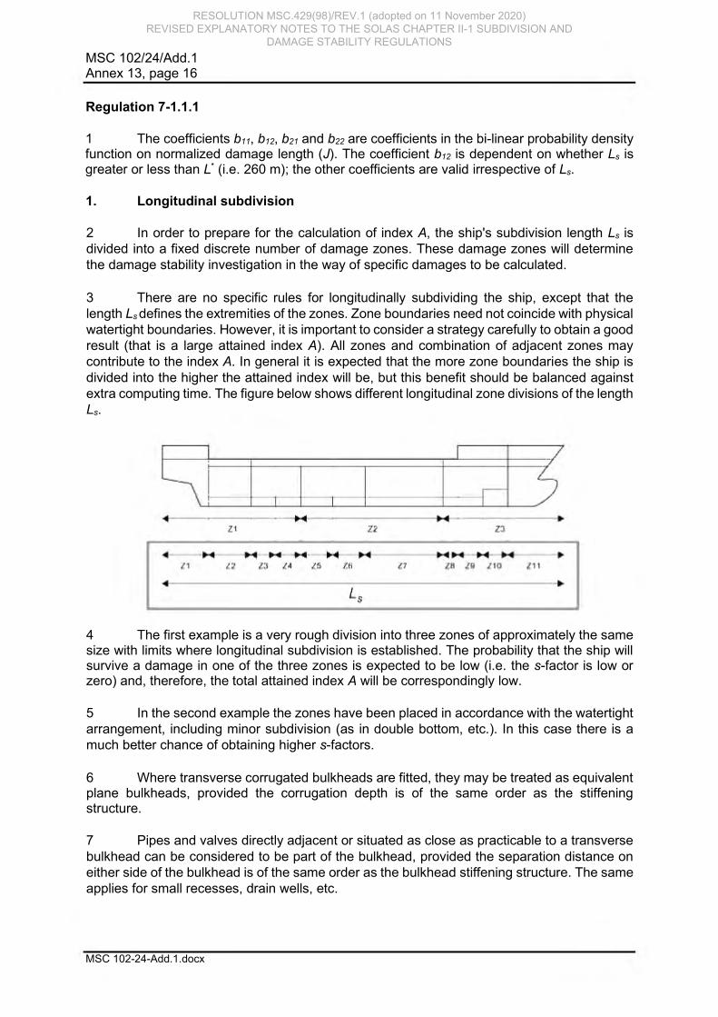
10 A damage having a transverse extent b and a vertical extent H2 leads to the flooding
of both wing compartment and hold; for b and H1 only the wing compartment is flooded.
The figure below illustrates a partial subdivision draught dp damage.
11 The same is valid if b-values are calculated for arrangements with sloped walls.
12 Pipes and valves directly adjacent or situated as close as practicable to a longitudinal bulkhead can be considered to be part of the bulkhead, provided the separation distance on either side of the bulkhead is of the same order as the bulkhead stiffening structure. The same applies for small recesses, drain wells, etc. REGULATION 7-2 – CALCULATION OF THE FACTOR si
General
1 Initial condition – an intact loading condition to be considered in the damage analysis described by the mean draught, vertical centre of gravity and the trim; or alternative parameters from where the same may be determined (e.g. displacement, GM and trim). There are three initial conditions corresponding to the three draughts ds, dp and dl.
2 Immersion limits – immersion limits are an array of points that are not to be immersed at various stages of flooding as indicated in regulations 7-2.5.2 and 7-2.5.3.
3 Openings – all openings need to be defined: both weathertight and unprotected. Openings are the most critical factor to preventing an inaccurate index A. If the final waterline immerses the lower edge of any opening through which progressive flooding takes place, the factor "s" may be recalculated taking such flooding into account. However, in this case the s value should also be calculated without taking into account progressive flooding and corresponding opening. The smallest s value should be retained for the contribution to the attained index.
Regulation 7-2.1
1 In cases where the GZ curve may include more than one "range" of positive righting
levers for a specific stage of flooding, only one continuous positive "range" of the GZ curve
may be used within the allowable range/heel limits for calculation purposes. Different stages
of flooding may not be combined in a single GZ curve.
RESOLUTION MSC.429(98)/REV.1 (adopted on 11 November 2020) REVISED EXPLANATORY NOTES TO THE SOLAS CHAPTER II-1 SUBDIVISION AND
DAMAGE STABILITY REGULATIONS
deep~st ,,ubdrttJsion draughtd,
...5L

MSC 102/24/Add.1 Annex 13, page 25
MSC 102-24-Add.1.docx
2 In figure 1, the s-factor may be calculated from the heel angle, range and corresponding GZmax of the first or second "range" of positive righting levers. In figure 2, only one s-factor can be calculated.
Regulation 7-2.2
Intermediate stages of flooding
1 The case of instantaneous flooding in unrestricted spaces in way of the damage zone does not require intermediate stage flooding calculations. Where intermediate stages of flooding calculations are necessary in connection with progressive flooding, flooding through non-watertight boundaries or cross-flooding, they should reflect the sequence of filling as well as filling level phases. Calculations for intermediate stages of flooding should be performed whenever equalization is not instantaneous, i.e. equalization is of a duration greater than 60 s. Such calculations consider the progress through one or more floodable (non-watertight) spaces, or cross-flooded spaces. Bulkheads surrounding refrigerated spaces, incinerator rooms and longitudinal bulkheads fitted with non-watertight doors are typical examples of structures that may significantly slow down the equalization of main compartments.
Flooding boundaries
2 If a compartment contains decks, inner bulkheads, structural elements and doors of sufficient tightness and strength to seriously restrict the flow of water, for intermediate stage flooding calculation purposes it should be divided into corresponding non-watertight spaces. It is assumed that the non-watertight divisions considered in the calculations are limited to "A" class fire-rated bulkheads and decks, and do not apply to "B" class fire-rated bulkheads normally used in accommodation areas (e.g. cabins and corridors). This guidance also relates to regulation 4.5. For spaces in the double bottom, in general, only main longitudinal structures with a limited number of openings have to be considered as flooding boundaries.
RESOLUTION MSC.429(98)/REV.1 (adopted on 11 November 2020) REVISED EXPLANATORY NOTES TO THE SOLAS CHAPTER II-1 SUBDIVISION AND
DAMAGE STABILITY REGULATIONS
Figme 1 GZ
heel rangei
0,2
Figme 2 GZ
heel
e, 0v

MSC 102/24/Add.1 Annex 13, page 26
MSC 102-24-Add.1.docx
Sequential flooding computation 3 For each damage scenario, the damage extent and location determine the initial stage of flooding. Calculations should be performed in stages, each stage comprising at least two intermediate filling phases in addition to the full phase per flooded space. Unrestricted spaces in way of damage should be considered as flooded immediately. Every subsequent stage involves all connected spaces being flooded simultaneously until an impermeable boundary or final equilibrium is reached. Unless the flooding process is simulated using time-domain methods, when a flooding stage leads to both a self-acting cross-flooding device and a non-watertight boundary, the self-acting cross-flooding device is assumed to act immediately and occur before the non-watertight boundary is breached. If due to the configuration of the subdivision in the ship it is expected that other intermediate stages of flooding are more onerous, then those should be investigated.
3.1 For each phase of a flooding stage (except the final full phase), the instantaneous transverse moment of this floodwater is calculated by assuming a constant volume of water at each heeling angle. The GZ curve is calculated with a constant intact displacement at all stages of flooding. Only one free surface needs to be assumed for water in spaces flooded during the current stage.
3.2 In the final full phase of each stage, the water level in rooms flooded during this stage reaches the outside sea level, so the lost buoyancy method can be used. The same method applies for every successive stage (added volume of water with a constant intact displacement for all phases before the final full phase of the stage in consideration), while each of the previous stages at the final full phase can be calculated with the lost buoyancy method.
3.3 The examples below present a simplified, sequential approach to intermediate stage down-flooding and cross-flooding. Because simultaneous down-flooding and cross-flooding is not accounted for, any time-to-flood calculated with this sequential approach should be conservative. Alternative approaches, such as time-domain flooding simulation, are also acceptable.
Example 1: Major damage with cross-flooding device
Stage 0: Unrestricted spaces in way of damage should be considered as flooded immediately (intermediate phases are not considered). The lost buoyancy method is applied as this is a full (final) phase. Provided the ship does not capsize and remains at a floating position from which cross-flooding can proceed, stage 0 need not be taken into account for the sfactor calculation as the first intermediate stage to be calculated is after 60 s. See cross-flooding/equalization explanatory note 5 below.
RESOLUTION MSC.429(98)/REV.1 (adopted on 11 November 2020) REVISED EXPLANATORY NOTES TO THE SOLAS CHAPTER II-1 SUBDIVISION AND
DAMAGE STABILITY REGULATIONS

MSC 102/24/Add.1 Annex 13, page 27
MSC 102-24-Add.1.docx
Stage 1: Cross-flooding of opposite room
An intermediate phase
Full (final) phase of flooding stage 1
Breach extent
Rooms within breach extent instantaneously flooded
Rooms flooded in previous stage treated in lost buoyancy method
Flood water is added, with one free surfa ce
Cross - flooded rooms
Cross - flooding device
Cross - flooded rooms in lost buoyancy method
Rooms flooded in previous stage treated in lost buoyancy method
RESOLUTION MSC.429(98)/REV.1 (adopted on 11 November 2020) REVISED EXPLANATORY NOTES TO THE SOLAS CHAPTER II-1 SUBDIVISION AND
DAMAGE STABILITY REGULATIONS
-
-
-
-
-

MSC 102/24/Add.1 Annex 13, page 28
MSC 102-24-Add.1.docx
Example 2: Minor damage with down-flooding and cross-flooding
Stage 0: Unrestricted spaces in way of damage should be considered as flooded immediately (intermediate phases are not considered). The lost buoyancy method is applied as this is a full (final) phase. Provided the ship does not capsize and remains at a floating position from which cross-flooding can proceed, stage 0 need not be taken into account for the sfactor calculation as the first intermediate stage to be calculated is after 60 s. See cross-flooding/equalization explanatory note 5 below.
STAGE 1: DOWN-FLOODING THROUGH NON-WATERTIGHT DECK
An intermediate phase
Final (full) phase of stage 1
Breach extent Rooms within breach extent instantaneously flooded
Rooms flooded in previous stage treated by lost buoyancy method
Floodwater is added with one common free surface
Down - flooded room
Rooms flooded in previous stage treated by lost buoyancy method
Down - flooded rooms treated by lost buoyancy method
RESOLUTION MSC.429(98)/REV.1 (adopted on 11 November 2020) REVISED EXPLANATORY NOTES TO THE SOLAS CHAPTER II-1 SUBDIVISION AND
DAMAGE STABILITY REGULATIONS

MSC 102/24/Add.1 Annex 13, page 29
MSC 102-24-Add.1.docx
STAGE 2: CROSS-FLOODING
An intermediate phase
Full (final) phase of stage 2
Cross-flooding/equalization
4 In general, cross-flooding is flooding of an undamaged space of the ship to reduce
the heel in the final equilibrium condition.
5 The cross-flooding time should be calculated in accordance with the Revised recommendation on a standard method for evaluating cross-flooding arrangements (resolution MSC.362(92)). If complete fluid equalization occurs in 60 s or less, it should be treated as instantaneous and no further calculations need to be carried out. Additionally, in cases where sfinal = 1 is achieved in 60 s or less, but equalization is not complete, instantaneous flooding may also be assumed if sfinal will not become reduced. In any cases where complete fluid equalization exceeds 60 s, the value of sintermediate after 60 s is the first intermediate stage to be considered. Only self-acting open cross-flooding arrangements without valves should be considered effective for instantaneous flooding cases.
6 Provided that the ship has a GZ greater than 0 and remains in a position from which cross-flooding can proceed, stage 0 need not be taken into account for the sfactor calculation as the first intermediate stage to be calculated is after 60 s.
Rooms flooded in previous stages, t reated by lost buoyancy method
Cross - flooding device
Floodwater is added with one free surface
Cross - flooded room
Rooms flooded in previous stages, treated by lost buoyancy method
Cross - flooded room treated by lost buoyancy method
RESOLUTION MSC.429(98)/REV.1 (adopted on 11 November 2020) REVISED EXPLANATORY NOTES TO THE SOLAS CHAPTER II-1 SUBDIVISION AND
DAMAGE STABILITY REGULATIONS
MSC 102/24/Add.1 Annex 13, page 30
MSC 102-24-Add.1.docx
7 Only cross-flooding devices which are sufficiently submerged below the external
waterline at stage 0 are to be used in the calculation for cross-flooding according to resolution
MSC.362(92). 8 If complete fluid equalization can be finalized in 10 min or less, the assessment of survivability is carried out using the formula in regulation 7-2.1.1 (i.e. as the smallest value of sintermediate or sfinal · smom) 9 In case the equalization time is longer than 10 min, sfinal is calculated for the floating position achieved after 10 min of equalization. This floating position is computed by calculating the amount of flood water according to resolution MSC.362(92) using interpolation, where the equalization time is set to 10 min, i.e. the interpolation of the flood water volume is made between the case before equalization (T=0) and the total calculated equalization time. For damage cases involving different cross-flooding devices serving different spaces, when the interpolation between the case before equalization (T=0) and the total calculated equalization time is needed for flood water volume calculation after 60 s or 10 min, the total equalization time is to be calculated separately for each cross-flooding device.
10 In any cases where complete fluid equalization exceeds 10 min, the value of sfinal used in the formula in regulation 7-2.1.1 should be the minimum of sfinal at 10 min or at final equalization.
11 The factor sintermediate,i may be used for cross-flooding stages if they are intermediate stages which are followed by other subsequent flooding stages (e.g. the flooding stages of non-watertight compartments).
Alternatives
12 As an alternative to the procedure described above in the explanatory notes for regulation 7-2.2, direct calculation using computational fluid dynamics (CFD), time-domain flooding simulations or model testing may be used to analyse intermediate stages of flooding and determine the time for equalization. Regulation 7-2.3
1 The formulation of sfinal,i is based on target values for GZ and Range to achieve s = 1. These values are defined as TGZmax and TRange.
2 If ro-ro spaces are damaged there might be the possibility of water accumulation on these deck spaces. To account for this, in any damage case where the ro-ro space is damaged the higher values for TGZmax and TRange are to be applied for the calculation of si.
Regulation 7-2.4.1.2
The parameter A (projected lateral area) used in this paragraph does not refer to the attained subdivision index.
Regulation 7-2.5.2.1
Unprotected openings
1 The flooding angle will be limited by immersion of such an opening. It is not necessary to define a criterion for non-immersion of unprotected openings at equilibrium, because if it is immersed, the range of positive GZ limited to flooding angle will be zero so "s" will be equal to zero.
RESOLUTION MSC.429(98)/REV.1 (adopted on 11 November 2020) REVISED EXPLANATORY NOTES TO THE SOLAS CHAPTER II-1 SUBDIVISION AND
DAMAGE STABILITY REGULATIONS

MSC 102/24/Add.1 Annex 13, page 31
MSC 102-24-Add.1.docx
2 An unprotected opening connects two rooms or one room and the outside. An unprotected opening will not be taken into account if the two connected rooms are flooded or none of these rooms are flooded. If the opening is connected to the outside, it will not be taken into account if the connected compartment is flooded. An unprotected opening does not need to be taken into account if it connects a flooded room or the outside to an undamaged room, if this room will be considered as flooded in a subsequent stage.
Openings fitted with a weathertight means of closing ("weathertight openings") 3 The survival "s" factor will be "0" if any such point is submerged at a stage which is considered as "final". Such points may be submerged during a stage or phase which is considered as "intermediate", or within the range beyond equilibrium. 4 If an opening fitted with a weathertight means of closure is submerged at equilibrium during a stage considered as intermediate, it should be demonstrated that this weathertight means of closure can sustain the corresponding head of water and that the leakage rate is negligible. 5 These points are also defined as connecting two rooms or one room and the outside, and the same principle as for unprotected openings is applied to take them into account or not. If several stages have to be considered as "final", a "weathertight opening" does not need to be taken into account if it connects a flooded room or the outside to an undamaged room if this room will be considered as flooded in a successive "final" stage.
Regulation 7-2.5.2.2 1 Partial immersion of the bulkhead deck may be accepted at final equilibrium. This provision is intended to ensure that evacuation along the bulkhead deck to the vertical escapes will not be impeded by water on that deck. A "horizontal evacuation route" in the context of this regulation means a route on the bulkhead deck connecting spaces located on and under this deck with the vertical escapes from the bulkhead deck required for compliance with SOLAS chapter II-2.
2 Horizontal evacuation routes on the bulkhead deck include only escape routes (designated as category 2 stairway spaces according to SOLAS regulation II-2/9.2.2.3 or as category 4 stairway spaces according to SOLAS regulation II-2/9.2.2.4 for passenger ships carrying not more than 36 passengers) used for the evacuation of undamaged spaces. Horizontal evacuation routes do not include corridors (designated as category 3 corridor spaces according to SOLAS regulation II-2/9.2.2.3 or as category 2 corridor spaces according to SOLAS regulation II-2/9.2.2.4 for passenger ships carrying not more than 36 passengers) or escape routes within a damaged zone. No part of a horizontal evacuation route serving undamaged spaces should be immersed.
3 si = 0 where it is not possible to access a stair leading up to the embarkation deck from an undamaged space as a result of flooding to the "stairway" or "horizontal stairway" on the bulkhead deck.
Regulation 7-2.5.3.1 1 The purpose of this paragraph is to provide an incentive to ensure that evacuation through a vertical escape will not be obstructed by water from above. The paragraph is intended for smaller emergency escapes, typically hatches, where fitting of a watertight or weathertight means of closure would otherwise exclude them from being considered as flooding points.
RESOLUTION MSC.429(98)/REV.1 (adopted on 11 November 2020) REVISED EXPLANATORY NOTES TO THE SOLAS CHAPTER II-1 SUBDIVISION AND
DAMAGE STABILITY REGULATIONS
MSC 102/24/Add.1 Annex 13, page 32
MSC 102-24-Add.1.docx
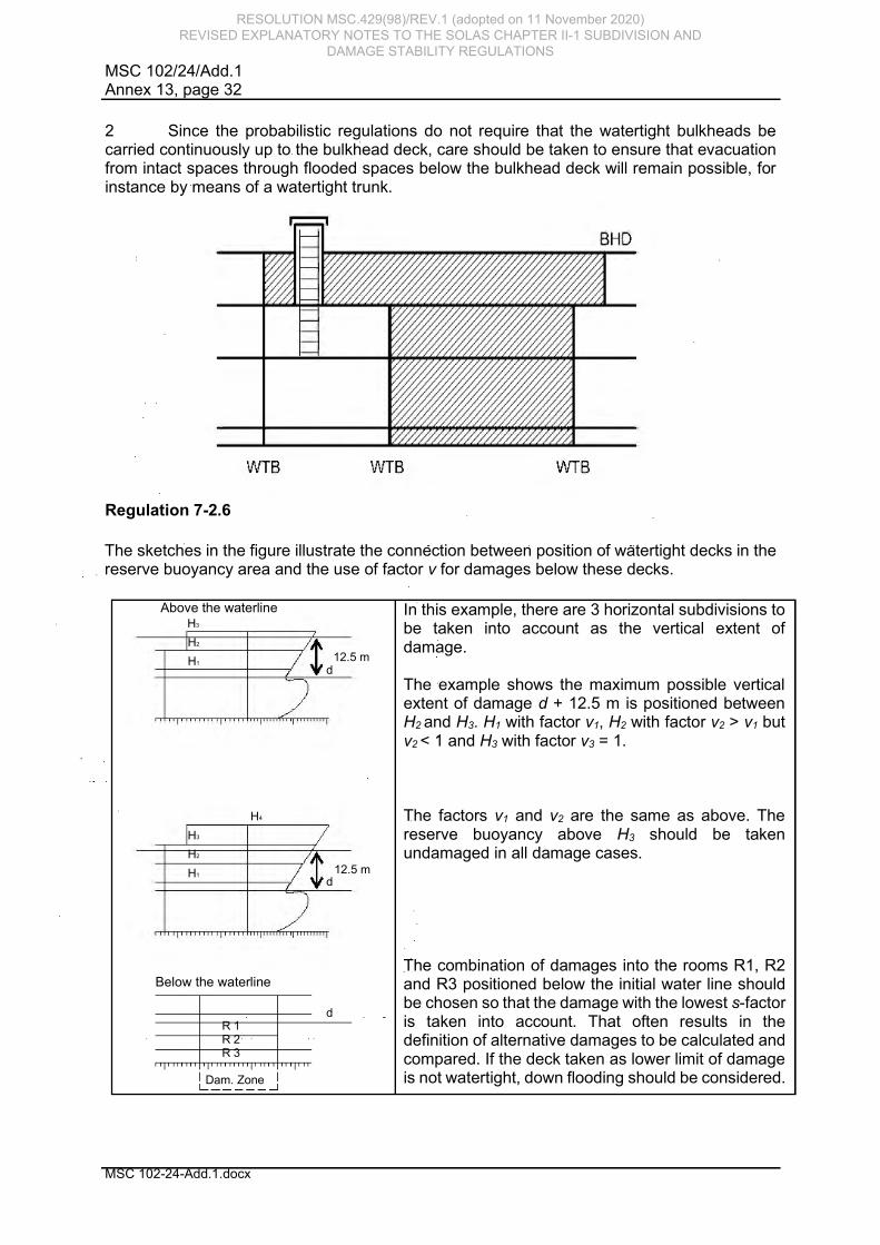
2 Since the probabilistic regulations do not require that the watertight bulkheads be carried continuously up to the bulkhead deck, care should be taken to ensure that evacuation from intact spaces through flooded spaces below the bulkhead deck will remain possible, for instance by means of a watertight trunk.
Regulation 7-2.6
The sketches in the figure illustrate the connection between position of watertight decks in the reserve buoyancy area and the use of factor v for damages below these decks.
Above the waterline
Below the waterline
In this example, there are 3 horizontal subdivisions to be taken into account as the vertical extent of damage. The example shows the maximum possible vertical extent of damage d + 12.5 m is positioned between H2 and H3. H1 with factor v1, H2 with factor v2 > v1 but v2 < 1 and H3 with factor v3 = 1. The factors v1 and v2 are the same as above. The reserve buoyancy above H3 should be taken undamaged in all damage cases. The combination of damages into the rooms R1, R2 and R3 positioned below the initial water line should be chosen so that the damage with the lowest s-factor is taken into account. That often results in the definition of alternative damages to be calculated and compared. If the deck taken as lower limit of damage is not watertight, down flooding should be considered.
1 R R 2 R 3
Dam. Zone
d
H 3 H 2
H 4
H 1 d
12.5 m
H 1 H 2 H 3
d 12.5 m
RESOLUTION MSC.429(98)/REV.1 (adopted on 11 November 2020) REVISED EXPLANATORY NOTES TO THE SOLAS CHAPTER II-1 SUBDIVISION AND
DAMAGE STABILITY REGULATIONS
WTB WTB WTB
I //t )
.. ··1······· 'I .. ' ., .,
I I
//t )
'"''I'"'"' 'I " ' ., .,
.. , ....... I., ......... , .... .I..., .. I I L _____ _J

MSC 102/24/Add.1 Annex 13, page 33
MSC 102-24-Add.1.docx
Regulation 7-2.6.1
The parameters x1 and x2 are the same as parameters x1 and x2 used in regulation 7-1.
REGULATION 7-3 – PERMEABILITY
Regulation 7-3.2
1 The following additional cargo permeabilities may be used:
Spaces Permeability at
draught ds
Permeability at
draught dp
Permeability at
draught dl
Timber cargo in holds 0.35 0.7 0.95
Wood chip cargo 0.6 0.7 0.95
2 Reference is made to MSC/Circ.998 (IACS unified interpretation regarding timber deck cargo in the context of damage stability requirements) regarding timber deck cargo.
Regulation 7-3.3
1 Concerning the use of other figures for permeability "if substantiated by calculations",
such permeabilities should reflect the general conditions of the ship throughout its service life
rather than specific loading conditions.
2 This paragraph allows for the recalculation of permeabilities. This should only be considered in cases where it is evident that there is a major discrepancy between the values shown in the regulation and the real values. It is not designed for improving the attained value of a deficient ship of regular type by the modification of chosen spaces in the ship that are known to provide significantly onerous results. All proposals should be considered on a case-by-case basis by the Administration and should be justified with adequate calculations and arguments.
REGULATION 8 – SPECIAL REQUIREMENTS CONCERNING PASSENGER SHIP STABILITY
Regulation 8.1
This regulation is intended to ensure a sufficient safety level if a large compartment is located aft of the collision bulkhead.
REGULATION 8-1 – SYSTEM CAPABILITIES AND OPERATIONAL INFORMATION AFTER A FLOODING CASUALTY ON PASSENGER SHIPS
Regulation 8-1.2
1 In the context of this regulation, "compartment" has the same meaning as defined under regulation 7-1 of these Explanatory Notes (i.e. an onboard space within watertight boundaries).
RESOLUTION MSC.429(98)/REV.1 (adopted on 11 November 2020) REVISED EXPLANATORY NOTES TO THE SOLAS CHAPTER II-1 SUBDIVISION AND
DAMAGE STABILITY REGULATIONS

MSC 102/24/Add.1 Annex 13, page 34
MSC 102-24-Add.1.docx
2 The purpose of the paragraph is to prevent any flooding of limited extent from immobilizing the ship. This principle should be applied regardless of how the flooding might occur. Only flooding below the bulkhead deck need be considered.
REGULATION 9 – DOUBLE BOTTOMS IN PASSENGER SHIPS AND CARGO SHIPS OTHER THAN TANKERS
Regulation 9.1
1 This regulation is intended to minimize the impact of flooding from a minor grounding. Special attention should be paid to the vulnerable area at the turn of the bilge. When justifying a deviation from fitting an inner bottom an assessment of the consequences of allowing a more extensive flooding than reflected in the regulation should be provided.
2 The determination regarding the requirement to fit a double bottom "as far as this is practicable and compatible with the design and proper working of the ship" is made, or should be accepted by, the Administration or a recognized organization acting on its behalf. 3 Compliance with the damage stability requirement in regulation 9.8 should not be considered as an equivalent optional requirement to the fitting of a dimensionally compliant double bottom. This is because a flooded watertight compartment, such as an engine-room, that complies with the damage stability requirement in regulation 9.8 is not equivalent to a flooded double bottom below that compartment. Compliance with the damage stability requirement in regulation 9.8 is intended to provide a minimum level of safety in cases when the fitting of a double bottom is not practicable or compatible with the design and proper working of the ship. Regulation 9.2
1 Except as provided in regulations 9.3 and 9.4, parts of the double bottom not extended for the full width of the ship as required by regulation 9.2 should be considered an unusual arrangement for the purpose of this regulation and should be handled in accordance with regulation 9.7. An example is provided below.
2 If an inner bottom is located higher than the partial subdivision draught dp, this should
be considered an unusual arrangement and is to be handled in accordance with regulation 9.7.
Regulations 9.3.2.2, 9.6 and 9.7
For cargo ships of less than 80 m in length (L), the alternative arrangements to provide a level of safety satisfactory to the Administration should be limited to compartments not having a double bottom, having an unusual bottom arrangement, or having an "other well" extending below the required double bottom height that is greater than the h/2 or 500 mm limit indicated in regulation 9.3.2.1. In these cases compliance with the bottom damage standard
B/20
RESOLUTION MSC.429(98)/REV.1 (adopted on 11 November 2020) REVISED EXPLANATORY NOTES TO THE SOLAS CHAPTER II-1 SUBDIVISION AND
DAMAGE STABILITY REGULATIONS
I I I

MS
C 1
02/2
4/A
dd.1
A
nne
x 1
3, p
ag
e 3
5
MS
C 1
02
-24
-Ad
d.1
.do
cx
in re
gu
latio
n 9
.8 s
hou
ld b
e d
em
onstra
ted a
ssum
ing th
at th
e d
am
ag
e w
ill only
occur b
etw
een
the tra
nsvers
e w
ate
rtight b
ulk
hea
ds in
co
mp
artm
ents
not h
avin
g a
dou
ble
botto
m, h
avin
g a
n
unu
sua
l botto
m a
rrang
em
ent, o
r havin
g a
n "o
ther w
ell" e
xte
nd
ing b
elo
w th
e re
qu
ired d
ou
ble
b
otto
m h
eig
ht th
at is
gre
ate
r than th
e h
/2 o
r 500
mm
limit in
dic
ate
d in
regu
latio
n 9
.3.2
.1.
Re
gu
latio
n 9
.6
1
An
y p
art o
f a p
asse
ng
er s
hip
or a
ca
rgo s
hip
of 8
0 m
in le
ngth
(L) a
nd u
pw
ard
s w
here
a
dou
ble
botto
m is
om
itted in
accord
an
ce w
ith re
gula
tion
9.1
, 9.4
or 9
.5 s
hall b
e c
apa
ble
of
with
sta
nd
ing b
otto
m d
am
age
s, a
s s
pecifie
d in
regu
latio
n 9
.8. T
he
inte
nt o
f this
pro
vis
ion is
to
sp
ecify
the c
ircu
msta
nces u
nd
er w
hic
h th
e A
dm
inis
tratio
n s
hou
ld re
qu
ire c
alc
ula
tion
s, w
hic
h
dam
age
exte
nts
to a
ssum
e a
nd
wh
at s
urv
iva
l crite
ria to
app
ly w
hen
doub
le b
otto
ms a
re n
ot
fitted.
2
The
d
efin
ition o
f "w
ate
rtight"
in re
gu
latio
n 2
.17 im
plie
s th
at
the stre
ng
th o
f in
ne
r b
otto
ms a
nd
oth
er b
ou
nd
arie
s a
ssum
ed to
be w
ate
rtight s
hou
ld b
e v
erifie
d if th
ey a
re to
be
co
nsid
ere
d e
ffectiv
e in
this
co
nte
xt.
Re
gu
latio
n 9
.7
The
refe
rence to
a "p
lane
" in re
gu
latio
n 9
.2 d
oe
s n
ot im
ply
that th
e s
urfa
ce o
f the in
ne
r botto
m
ma
y n
ot b
e s
tepp
ed
in th
e v
ertic
al d
irectio
n. M
inor s
teps a
nd
recesses n
eed
not b
e c
onsid
ere
d
unu
sua
l arra
ng
em
ents
for th
e p
urp
ose o
f this
para
gra
ph
as lo
ng a
s n
o p
art o
f the in
ne
r botto
m
is lo
cate
d b
elo
w th
e re
fere
nce
pla
ne. D
isco
ntin
uitie
s in
wa
y o
f win
g ta
nks a
re c
overe
d b
y
regu
latio
n 9
.4.
R
eg
ula
tion
9.8
1
F
or s
hip
s to
wh
ich
the p
roba
bilis
tic d
am
age
sta
bility
requ
irem
ents
of p
art B
-1 a
pp
ly,
the te
rm "a
ll se
rvic
e c
onditio
ns" u
sed
in th
is p
ara
gra
ph
me
an
s th
e th
ree
loadin
g c
ond
itions w
ith
all
trims u
sed to
ca
lcu
late
th
e a
ttain
ed su
bd
ivis
ion in
de
x A
. F
or
sh
ips n
ot
su
bje
ct
to th
e
pro
ba
bilis
tic d
am
age s
tab
ility re
qu
irem
ents
in p
art B
-1, s
uch a
s c
arg
o s
hip
s th
at c
om
ply
with
th
e
sub
div
isio
n
and
dam
age
sta
bility
re
qu
irem
ents
o
f oth
er
instru
men
ts
as
allo
we
d
by
regu
latio
n II-1
/4.2
.1.2
and
ca
rgo s
hip
s o
f less th
an
80 m
in le
ngth
(L), "a
ll se
rvic
e c
ond
itions"
me
an
s th
at th
e lim
it cu
rve
s o
r table
s re
qu
ired b
y re
gu
latio
n 5
-1.2
.1 s
hou
ld in
clu
de
va
lues
ca
lcu
late
d
for
the
sam
e
dra
ug
ht
and
trim
rang
e(s
) a
s
for
the
oth
er
app
lica
ble
sta
bility
re
qu
irem
ents
. 2
The
dam
age
exte
nts
sp
ecifie
d in
this
para
gra
ph
sh
ou
ld b
e a
pp
lied to
all p
arts
of th
e
sh
ip w
here
no d
ou
ble
botto
m is
fitted, a
s p
erm
itted
by re
gu
latio
ns 9
.1, 9
.4 o
r 9.5
, and in
clu
de
any a
dja
ce
nt s
pace
s lo
cate
d w
ithin
the e
xte
nt o
f dam
age
. Sm
all w
ells
in a
ccord
ance
with
re
gu
latio
n 9
.3.1
do n
ot n
ee
d to
be c
onsid
ere
d d
am
age
d e
ven
if with
in th
e e
xte
nt o
f the d
am
age
. P
ossib
le p
ositio
ns o
f the d
am
age
s a
re s
how
n in
an
exam
ple
be
low
(parts
of th
e s
hip
not fitte
d
with
a d
ou
ble
botto
m a
re s
had
ed
; the d
am
age
s to
be a
ssum
ed a
re in
dic
ate
d b
y b
oxes).
RESO
LUTIO
N M
SC.429(98)/R
EV.1 (adopted on 11 Novem
ber 2020) R
EVISED EXPLAN
ATOR
Y NO
TES TO TH
E SOLAS C
HAPTER
II-1 SUBD
IVISION
AND
D
AMAG
E STABILITY REG
ULATIO
NS
B/20
- · - ·1 · • · - · - · -

MSC 102/24/Add.1 Annex 13, page 36
MSC 102-24-Add.1.docx
Regulation 9.9
1 For the purpose of identifying "large lower holds", horizontal surfaces having a
continuous deck area greater than approximately 30% in comparison with the waterplane area
at subdivision draught should be taken to be located anywhere in the affected area of the ship.
For the alternative bottom damage calculation, a vertical extent of B/10 or 3 m, whichever is
less, should be assumed.
2 The increased minimum double bottom height of not more than B/10 or 3 m, whichever is less, for passenger ships with large lower holds, is applicable to holds in direct contact with the double bottom. Typical arrangements of ro-ro passenger ships may include a large lower hold with additional tanks between the double bottom and the lower hold, as shown in the figure below. In such cases, the vertical position of the double bottom required to be B/10 or 3 m, whichever is less, should be applied to the lower hold deck, maintaining the required double bottom height of B/20 or 2 m, whichever is less (but not less than 760 mm). The figure below shows a typical arrangement of a modern ro-ro passenger ferry.
> B /10
> B / 2 0
B
RESOLUTION MSC.429(98)/REV.1 (adopted on 11 November 2020) REVISED EXPLANATORY NOTES TO THE SOLAS CHAPTER II-1 SUBDIVISION AND
DAMAGE STABILITY REGULATIONS
I r--- 1 I / I i--.._ I
I _,,,- I I I --~ I I ----- r---..___ I
::::J I I u , .
-- I I ____, i-----
I J I I ~
I _ , ... P'" I I _L.--,- -1
' I
' I
' I
• _, I ·- I
>B/10
B

MSC 102/24/Add.1 Annex 13, page 37
MSC 102-24-Add.1.docx
REGULATION 10 – CONSTRUCTION OF WATERTIGHT BULKHEADS
Regulation 10.1
For the treatment of steps in the bulkhead deck of passenger ships see explanatory notes for regulation 13. For the treatment of steps in the freeboard deck of cargo ships see explanatory notes for regulation 13-1.
REGULATION 12 – PEAK AND MACHINERY SPACE BULKHEADS, SHAFT TUNNELS,
ETC.
Regulation 12.6.1
For cargo ships, the following figures show examples of suitable butterfly valve arrangements:
Figure 1
RESOLUTION MSC.429(98)/REV.1 (adopted on 11 November 2020) REVISED EXPLANATORY NOTES TO THE SOLAS CHAPTER II-1 SUBDIVISION AND
DAMAGE STABILITY REGULATIONS
UistJ_ol.'~ J?iece(Penctmti,,n l>i«-c)
U-ottom 8bell.

MSC 102/24/Add.1 Annex 13, page 38
MSC 102-24-Add.1.docx
Figure 2
As butterfly valves must be capable of being remotely operated the following shall apply:
.1
the actuator shall be of a double acting type;
.2
when subject to loss of power, the actuator shall remain in its current
position; and
.3 when subject to loss of power, the valve shall be able to be manually
operated.
Regulation 12.10
1 In cargo ships the after engine-room bulkhead can be regarded as the afterpeak bulkhead provided that the after peak adjoins the engine-room. 2 In cargo ships with a raised quarter deck, it may be impracticable to extend the afterpeak bulkhead to the freeboard deck as the freeboard deck does not extend to the aft perpendicular. Provided that the afterpeak bulkhead extends above the deepest load line, and that all rudderstock bearings are housed in a watertight compartment without open connection to spaces located in front of the afterpeak bulkhead, termination of the afterpeak bulkhead on a watertight deck lower than the freeboard deck can be accepted by the Administration.
RESOLUTION MSC.429(98)/REV.1 (adopted on 11 November 2020) REVISED EXPLANATORY NOTES TO THE SOLAS CHAPTER II-1 SUBDIVISION AND
DAMAGE STABILITY REGULATIONS
Pltru
Distauct? f>iec~ (l'f:UetNltlOll Pie<-e)
ButtE!lity V al\'e

MSC 102/24/Add.1 Annex 13, page 39
MSC 102-24-Add.1.docx
Regulation 12.11
In cargo ships a stern tube enclosed in a watertight space of moderate volume, such as an afterpeak tank, where the inboard end of the stern tube extends through the afterpeak/engine-room watertight bulkhead into the engine-room, is considered to be an acceptable solution satisfying the requirement of this regulation, provided the inboard end of the stern tube is effectively sealed at the afterpeak/engine-room bulkhead by means of an approved watertight/oiltight gland system. REGULATION 13 – OPENINGS IN WATERTIGHT BULKHEADS BELOW THE
BULKHEAD DECK IN PASSENGER SHIPS
General – Steps in the bulkhead deck
1 If the transverse watertight bulkheads in a region of the ship are carried to a higher deck which forms a vertical step in the bulkhead deck, openings located in the bulkhead at the step may be considered as being located above the bulkhead deck. Such openings should then comply with regulation 17 and should be taken into account when applying regulation 7-2.
2 All openings in the shell plating below the upper deck throughout that region of the ship should be treated as being below the bulkhead deck and the provisions of regulation 15 should be applied. See figure below.
RESOLUTION MSC.429(98)/REV.1 (adopted on 11 November 2020) REVISED EXPLANATORY NOTES TO THE SOLAS CHAPTER II-1 SUBDIVISION AND
DAMAGE STABILITY REGULATIONS
steering gear-. room
Raised quarter dedc \
oecommodatlon '• r-rccbo(lrd deck
'
Engine room
:";:-;!,-,.--------,F,-O<W-Lar-,d'""ER,-_;\Base line
b<ilkheod bulkhei>d ,
ond
aftef peJlc
b<ilkheod
' I I
accommodation
• - • ~ • - - - • -centreline. - .
\ \ \
I I \ I I ·-·--,;-
\ I \ I
\ I
I

MSC 102/24/Add.1 Annex 13, page 40
MSC 102-24-Add.1.docx
1 Bulkhead deck 2 Considered as located above the bulkhead deck
3 Ship's side 4 Considered as located below the bulkhead deck
Regulation 13.2.3
1 For closed piping systems compliance with this regulation is achieved if approved pipe penetrations are fitted at the crossing of watertight bulkheads to ensure that heat-sensitive pipes outside the space affected by the fire remain intact, so that any flooding of the fire affected space does not cause progressive flooding through the piping or pipe penetration.
1.1 For open piping systems compliance with this regulation is achieved if approved pipe penetrations are fitted at the crossing of watertight bulkheads as are required for closed piping systems, and additionally each pipe connection to a watertight compartment is fitted with an isolation or non-return valve, as appropriate, to prevent progressive flooding through the piping system after a fire. As an alternative to fitting an isolation or non-return valve, pipes may be routed above the damaged waterline in such a way that progressive flooding is prevented, taking into account the dynamic movements of the ship in a damaged condition.
1.2 However, progressive flooding may be taken into account in accordance with SOLAS regulation 7-2.5.4 instead.
2 For the purpose of this explanatory note the following definitions apply:
A closed piping system is a piping system without openings in multiple watertight compartments.
An open piping system is a piping system with openings in multiple watertight compartments.
3 Materials used in systems which penetrate watertight bulkheads should be of sufficient strength after exposure to heat or be considered as part of an open piping system.
3.1 Closing devices using intumescent material (swelling when exposed to heat) for open piping systems should not be considered equivalent to the fitting of a valve, since the fire might be located too far from the device to create a watertight seal.
RESOLUTION MSC.429(98)/REV.1 (adopted on 11 November 2020) REVISED EXPLANATORY NOTES TO THE SOLAS CHAPTER II-1 SUBDIVISION AND
DAMAGE STABILITY REGULATIONS
I I I I I I
I I -------7---------r--------

MS
C 1
02/2
4/A
dd.1
A
nne
x 1
3, p
ag
e 4
1
MS
C 1
02
-24
-Ad
d.1
.do
cx
4
Ap
pro
val o
f pip
e p
en
etra
tions fitte
d to
ensure
the w
ate
rtight in
tegrity
of a
bu
lkh
ea
d o
r d
eck w
here
hea
t-se
nsitiv
e m
ate
rials
are
used s
hou
ld in
clu
de
a p
roto
typ
e te
st o
f wa
tertig
htn
ess
afte
r h
avin
g
und
erg
on
e
the
sta
nd
ard
fire
te
st
app
rop
riate
fo
r th
e
loca
tion
in
w
hic
h
the
pen
etra
tions a
re to
be in
sta
lled
2.
4.1
T
he
fire te
ste
d p
ipe p
ene
tratio
n s
hou
ld th
en b
e te
ste
d to
a te
st p
ressu
re o
f not le
ss
than
1.5
time
s th
e d
esig
n p
ressure
as d
efin
ed
in re
gu
latio
n 2
.18. T
he p
ressu
re s
hou
ld b
e
app
lied to
the
sam
e s
ide o
f the d
ivis
ion a
s th
e fire
test.
4.2
T
he
fire te
ste
d p
ipe p
en
etra
tion s
hou
ld b
e te
ste
d fo
r a p
erio
d o
f at le
ast 3
0 m
in u
nd
er
hydra
ulic
pre
ssure
e
qu
al
to th
e te
st
pre
ssu
re,
bu
t m
inim
um
1
.0 b
ar.
The
re s
hou
ld b
e n
o
leaka
ge
du
ring th
is te
st.
4.3
T
he
fire te
ste
d p
ipe p
en
etra
tion s
hou
ld c
ontin
ue to
be te
ste
d fo
r a fu
rther 3
0 m
in w
ith
the te
st p
ressu
re. T
he q
ua
ntity
of w
ate
r leaka
ge
is n
ot to
excee
d a
tota
l of 1
litre.
4.4
T
he
p
roto
typ
e
test
sho
uld
b
e
co
nsid
ere
d
va
lid
only
fo
r th
e
pip
e
typ
olo
gy
(e.g
. therm
opla
stic
a
nd m
ultila
yer),
pre
ssure
cla
sse
s,
the m
axim
um
/min
imu
m
dim
ensio
ns
teste
d, a
nd th
e ty
pe a
nd fire
ratin
g o
f the d
ivis
ion te
ste
d.
5
The
p
ressure
te
st
nee
d n
ot
be carrie
d o
ut
on th
e h
ot
pen
etra
tion
arra
nge
me
nt.
Am
ple
time m
ay b
e g
iven
to p
rep
are
for th
e p
ressu
re te
st, i.e
. dis
ma
ntlin
g th
e fire
testin
g
equip
me
nt a
nd rig
gin
g th
e p
ressure
test e
qu
ipm
en
t. 5.1
T
he
pre
ssure
test s
hou
ld b
e c
arrie
d o
ut w
ith th
e p
ipe s
ectio
n u
sed in
the fire
test s
till in
pla
ce.
5.2
A
ny p
ipe in
sula
tion
fitted fo
r the p
urp
ose o
f the fire
test m
ay b
e re
mo
ve
d b
efo
re th
e
pre
ssu
re te
st.
5.3
P
roto
typ
e te
stin
g n
ee
d n
ot b
e c
arrie
d o
ut if th
e p
ipe p
en
etra
tion is
ma
de o
f ste
el o
r e
qu
iva
lent m
ate
rial h
avin
g a
thic
kn
ess o
f 3 m
m o
r gre
ate
r and
a le
ng
th o
f not le
ss th
an 9
00
mm
(p
refe
rab
ly
450
m
m
on
each
sid
e
of
the
d
ivis
ion),
and
there
a
re
no
ope
nin
gs.
Su
ch p
en
etra
tion
s s
hall b
e s
uita
bly
insula
ted b
y e
xte
nsio
n o
f the in
sula
tion
at th
e s
am
e le
vel
of th
e d
ivis
ion. S
ee a
lso
regu
latio
n II-2
/9.3
.1 w
ith re
spe
ct to
pip
ing. H
ow
eve
r, the p
en
etra
tion
mu
st s
till co
mp
ly w
ith th
e w
ate
rtight in
teg
rity re
qu
irem
ent in
regu
latio
n 2
.17.
Re
gu
latio
n 1
3.4
In
ca
ses w
here
ma
in a
nd a
uxilia
ry p
rop
uls
ion m
ach
inery
sp
ace
s, in
clu
din
g b
oile
rs s
erv
ing th
e
nee
ds fo
r pro
pu
lsio
n, a
re d
ivid
ed
by w
ate
rtight lo
ng
itudin
al b
ulk
hea
ds in
ord
er to
com
ply
with
re
du
nd
an
cy re
qu
irem
ents
(e.g
. accord
ing to
regu
latio
n 8
-1.2
), one
wa
tertig
ht d
oor in
each
w
ate
rtight b
ulk
hea
d m
ay b
e p
erm
itted, a
s s
how
n in
the fig
ure
belo
w.
2
Refe
r to th
e re
qu
irem
en
ts fo
r A-c
lass d
ivis
ion
se
t ou
t in p
art 3
of a
nn
ex 1
to th
e 2
01
0 F
TP
Cod
e.
RESO
LUTIO
N M
SC.429(98)/R
EV.1 (adopted on 11 Novem
ber 2020) R
EVISED EXPLAN
ATOR
Y NO
TES TO TH
E SOLAS C
HAPTER
II-1 SUBD
IVISION
AND
D
AMAG
E STABILITY REG
ULATIO
NS
W.T W.T ~
eiei 1 □□
ll~ffll W.T W.T ~

MSC 102/24/Add.1 Annex 13, page 42
MSC 102-24-Add.1.docx
REGULATION 13-1 – OPENINGS IN WATERTIGHT BULKHEADS AND INTERNAL
DECKS IN CARGO SHIPS
Regulation 13-1.1
1 If the transverse watertight bulkheads in a region of the ship are carried to a higher deck than in the remainder of the ship, openings located in the bulkhead at the step may be considered as being located above the freeboard deck. 2 All openings in the shell plating below the upper deck throughout that region of the ship should be treated as being below the freeboard deck, similar to the bulkhead deck for passenger ships (see relevant figure under regulation 13 above), and the provisions of regulation 15 should be applied.
REGULATION 15 – OPENINGS IN THE SHELL PLATING BELOW THE BULKHEAD
DECK OF PASSENGER SHIPS AND THE FREEBOARD DECK OF
CARGO SHIPS
General – Steps in the bulkhead deck and freeboard deck
For the treatment of steps in the bulkhead deck of passenger ships see explanatory notes for regulation 13. For the treatment of steps in the freeboard deck of cargo ships see explanatory notes for regulation 13-1.
REGULATION 15-1 – EXTERNAL OPENINGS IN CARGO SHIPS
Regulations 15-1.1 to 15-1.3 apply to cargo ships which are subject to the damage stability analysis required in part B-1 or other IMO instruments.
Regulation 15-1.1
With regard to air-pipe closing devices, they should be considered weathertight closing devices (not watertight). This is consistent with their treatment in regulation 7-2.5.2.1. However, in the context of regulation 15-1, "external openings" are not intended to include air-pipe openings.
REGULATION 16 – CONSTRUCTION AND INITIAL TESTS OF WATERTIGHT
CLOSURES
General
These requirements are only to establish a general design standard for watertight closures. They are not intended to require any non-watertight hatches to be watertight, nor do they override the requirements of the International Convention on Load Lines.
Regulation 16.2
Large doors, hatches or ramps on passenger and cargo ships, of a design and size that would make pressure testing impracticable, may be exempted from regulation 16.2, provided it is demonstrated by calculations that the doors, hatches or ramps maintain watertightness at design pressure with a proper margin of resistance. Where such doors utilize gasket seals, a prototype pressure test to confirm that the compression of the gasket material is capable of accommodating any deflection, revealed by the structural analysis, should be carried out. After installation every such door, hatch or ramp should be tested by means of a hose test or equivalent.
RESOLUTION MSC.429(98)/REV.1 (adopted on 11 November 2020) REVISED EXPLANATORY NOTES TO THE SOLAS CHAPTER II-1 SUBDIVISION AND
DAMAGE STABILITY REGULATIONS

MSC 102/24/Add.1 Annex 13, page 43
MSC 102-24-Add.1.docx
Note: See explanatory notes for regulation 13 for additional information regarding the treatment of steps in the bulkhead deck of passenger ships. See explanatory notes for regulation 13-1 for additional information regarding the treatment of steps in the freeboard deck of cargo ships.
REGULATION 17 – INTERNAL WATERTIGHT INTEGRITY OF PASSENGER SHIPS
ABOVE THE BULKHEAD DECK
General – Steps in the bulkhead deck
For the treatment of steps in the bulkhead deck of passenger ships see explanatory notes for regulation 13.
Regulation 17.1
1 Sliding watertight doors with a reduced pressure head that are located above the bulkhead deck and which are immersed in the final or during any intermediate stage of flooding should comply fully with the requirements of regulation 13. These types of sliding watertight doors tested with reduced pressure head must not be immersed at any stage of flooding by a head of water higher than the tested pressure head. See figure 1 below. These sliding watertight doors shall be kept closed during navigation in compliance with the requirements of regulation 22 and this should be clearly indicated in the damage control information required by regulation 19.
2 If watertight doors are located above the worst final and above the worst intermediate waterline in damage cases contributing to the attained subdivision index A, but within the area where the door becomes intermittently immersed (fully or partly) at angles of heel in the required range of positive stability beyond the equilibrium position, such doors are to be power-operated and remotely controlled sliding semi-watertight doors complying with the requirements of regulation 13, except that the scantlings and sealing requirements could be reduced to the maximum head of water caused by the waterline being intermittently immersed (see figure 1 below). These doors should be closed in case of damage and this should be clearly indicated in the damage control information required by regulation 19.
Figure 1
3 The use of watertight sliding doors above the bulkhead deck affects the escape provisions of regulation II-2/13. When such doors are used above the bulkhead deck, there should be at least two means of escape from each main vertical zone or similarly restricted space or group of spaces, at least one of which should be independent of watertight doors and at least one of which should give access to a stairway forming a vertical escape. Sliding watertight doors that will be used frequently by passengers must not create a tripping hazard.
RESOLUTION MSC.429(98)/REV.1 (adopted on 11 November 2020) REVISED EXPLANATORY NOTES TO THE SOLAS CHAPTER II-1 SUBDIVISION AND
DAMAGE STABILITY REGULATIONS
IMt•ntiilllliilMliy Jmm .. lltriN11J'-
lnt«mtdllfM h"4 •11111•
BulkhoodOool<

MSC 102/24/Add.1 Annex 13, page 44
MSC 102-24-Add.1.docx
4 Doors fitted above the bulkhead deck which are required to meet both fire protection and watertight requirements should comply with the fire requirements in regulation II-2/9.4.1.1 and the watertight requirements in paragraphs 1 and 2 above. Notwithstanding the ultimate sentence of regulation II-2/9.4.1.1.2, watertight doors fitted above the bulkhead deck should be insulated to the standard required by table 9.1 and regulation II-2/9.2.2.1.1.1 or by table 9.3 and regulation II-2/9.2.2.1.1.2 as appropriate. The door must be capable of operation using both the remote fire door control circuit and the remote watertight door control circuit. If two doors are fitted, they must be capable of independent operation. The operation of either door separately must not preclude closing of the other door. Both doors must be capable of being operated from either side of the bulkhead.
Regulation 17.3
This paragraph is intended to ensure that progressive flooding through air pipes of volumes located above a horizontal division in the superstructure, which is considered as a watertight boundary when applying regulation 7-2.6.1.1, will be taken into consideration if a side or bottom damage would cause flooding via tanks or spaces located below the waterline.
REGULATION 17-1 – INTEGRITY OF THE HULL AND SUPERSTRUCTURE, DAMAGE PREVENTION AND CONTROL ON RO-RO PASSENGER SHIPS
Regulations 17-1.1.1 and 17-1.1.3 apply only to direct accesses from a ro-ro space to spaces located below the bulkhead deck. The operation of doors in bulkheads separating a ro-ro space and other spaces should be limited to compliance with regulation 23.3.
REGULATION 22 – PREVENTION AND CONTROL OF WATER INGRESS, ETC.
The word "port" used in this regulation includes all berths and sheltered locations where loading and/or discharging may take place.
Accomodation Ro-ro deck
WTD
RESOLUTION MSC.429(98)/REV.1 (adopted on 11 November 2020) REVISED EXPLANATORY NOTES TO THE SOLAS CHAPTER II-1 SUBDIVISION AND
DAMAGE STABILITY REGULATIONS
·-- ------1--------------~----- ---------- --------

MSC 102/24/Add.1 Annex 13, page 45
MSC 102-24-Add.1.docx
APPENDIX
GUIDELINES FOR THE PREPARATION OF SUBDIVISION
AND DAMAGE STABILITY CALCULATIONS
GENERAL
1.1 Purpose of the Guidelines
1.1.1 These Guidelines serve the purpose of simplifying the process of the damage stability analysis, as experience has shown that a systematic and complete presentation of the particulars results in considerable saving of time during the approval process.
1.1.2 A damage stability analysis serves the purpose of providing proof of the damage stability standard required for the respective ship type. At present, two different calculation methods, the deterministic concept and the probabilistic concept are applied.
1.2 Scope of analysis and documentation on board
1.2.1 The scope of subdivision and damage stability analysis is determined by the required damage stability standard and aims at providing the ship's master with clear intact stability requirements. In general, this is achieved by determining KG-respective GM-limit curves, containing the admissible stability values for the draught range to be covered.
1.2.2 Within the scope of the analysis thus defined, all potential or necessary damage conditions will be determined, taking into account the damage stability criteria, in order to obtain the required damage stability standard. Depending on the type and size of ship, this may involve a considerable amount of analyses.
1.2.3 Referring to SOLAS chapter II-1, regulation 19, the necessity to provide the crew with the relevant information regarding the subdivision of the ship is expressed, therefore plans should be provided and permanently exhibited for the guidance of the officer in charge. These plans should clearly show for each deck and hold the boundaries of the watertight compartments, the openings therein with means of closure and position of any controls thereof, and the arrangements for the correction of any list due to flooding. In addition, Damage Control Booklets containing the aforementioned information should be available.
DOCUMENTS FOR SUBMISSION
2.1 Presentation of documents
The documentation should begin with the following details: principal dimensions, ship type, designation of intact conditions, designation of damage conditions and pertinent damaged compartments, KG-respective GM-limit curve.
RESOLUTION MSC.429(98)/REV.1 (adopted on 11 November 2020) REVISED EXPLANATORY NOTES TO THE SOLAS CHAPTER II-1 SUBDIVISION AND
DAMAGE STABILITY REGULATIONS

MSC 102/24/Add.1 Annex 13, page 46
MSC 102-24-Add.1.docx
2.2 General documents For the checking of the input data, the following should be submitted: .1 main dimensions;
.2 lines plan, plotted or numerical;
.3
hydrostatic data and cross curves of stability (including drawing of the buoyant hull);
.4
definition of sub-compartments with moulded volumes, centres of gravity and permeability;
.5
layout plan (watertight integrity plan) for the sub-compartments with all internal and external opening points including their connected sub-compartments, and particulars used in measuring the spaces, such as general arrangement plan and tank plan. The subdivision limits, longitudinal, transverse and vertical, should be included;
.6
light service condition;
.7
load line draught;
.8
coordinates of opening points with their level of tightness (e.g. weathertight, unprotected);
.9
watertight door location with pressure calculation;
.10
side contour and wind profile;
.11
cross and down flooding devices and the calculations thereof according to resolution MSC.362(92) with information about diameter, valves, pipe lengths and coordinates of inlet/outlet;
.12
pipes in damaged area when the destruction of these pipes results in progressive flooding; and
.13 damage extensions and definition of damage cases.
2.3 Special documents
The following documentation of results should be submitted.
RESOLUTION MSC.429(98)/REV.1 (adopted on 11 November 2020) REVISED EXPLANATORY NOTES TO THE SOLAS CHAPTER II-1 SUBDIVISION AND
DAMAGE STABILITY REGULATIONS
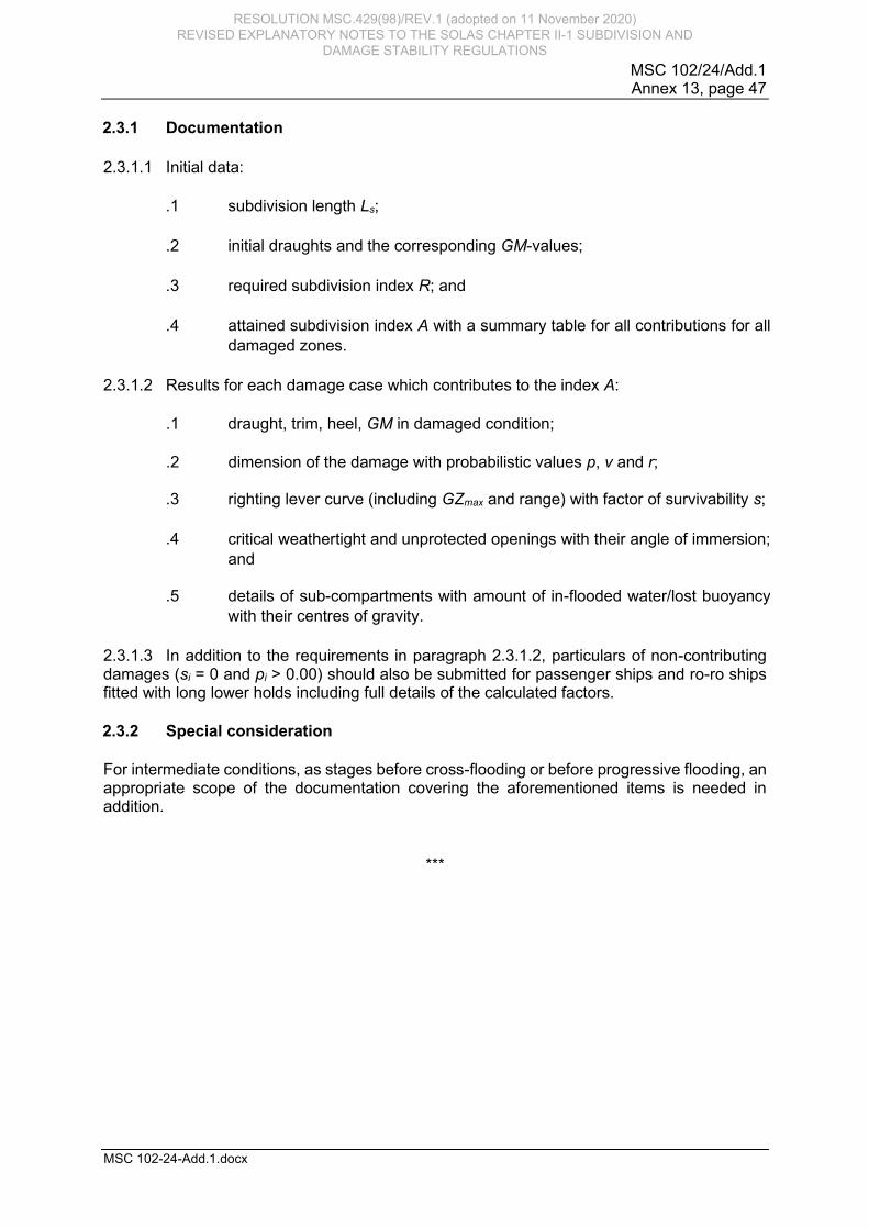
MSC 102/24/Add.1 Annex 13, page 47
MSC 102-24-Add.1.docx
2.3.1 Documentation
2.3.1.1 Initial data:
.1
subdivision length Ls;
.2
initial draughts and the corresponding GM-values;
.3
required subdivision index R; and
.4 attained subdivision index A with a summary table for all contributions for all
damaged zones.
2.3.1.2 Results for each damage case which contributes to the index A:
.1 draught, trim, heel, GM in damaged condition;
.2 dimension of the damage with probabilistic values p, v and r;
.3
righting lever curve (including GZmax and range) with factor of survivability s;
.4
critical weathertight and unprotected openings with their angle of immersion;
and
.5 details of sub-compartments with amount of in-flooded water/lost buoyancy
with their centres of gravity.
2.3.1.3 In addition to the requirements in paragraph 2.3.1.2, particulars of non-contributing damages (si = 0 and pi > 0.00) should also be submitted for passenger ships and ro-ro ships fitted with long lower holds including full details of the calculated factors.
2.3.2 Special consideration
For intermediate conditions, as stages before cross-flooding or before progressive flooding, an appropriate scope of the documentation covering the aforementioned items is needed in addition.
***
RESOLUTION MSC.429(98)/REV.1 (adopted on 11 November 2020) REVISED EXPLANATORY NOTES TO THE SOLAS CHAPTER II-1 SUBDIVISION AND
DAMAGE STABILITY REGULATIONS

RESOLUTION MSC.429(98)/REV.1 (adopted on 11 November 2020) REVISED EXPLANATORY NOTES TO THE SOLAS CHAPTER II-1 SUBDIVISION AND
DAMAGE STABILITY REGULATIONS