RELOADED! - MSC Software Corporation
36
MSC.Software Magazine Volume I | Winter 2011 REALITY simulating MSC RELOADED! Dominic speaks about Simulating Reality, Delivering Certainty ADAMS GOES REAL-TIME DESIGN INTEGRATION BETWEEN AUTO SUPPLIERS & OEMs VI-GRADE BUILDING LARGE FEA MODELS EFFICIENTLY WITH TEMPLATES OPTIMEC CONSULTANTS FEA HELPS REDUCE TIME TO DESIGN EXHAUST EXPANSION JOINTS AMERICAN BOA
-
Upload
khangminh22 -
Category
Documents
-
view
0 -
download
0
Transcript of RELOADED! - MSC Software Corporation

MSC.Software Magazine Volume I | Winter 2011
REALITYsimulating
MSC RELOADED!
Dominic speaks about Simulating Reality,
Delivering Certainty
ADAMS GOES REAL-TIME DESIGN INTEGRATION BETWEEN
AUTO SUPPLIERS & OEMsVI-GRADE
BUILDING LARGE FEA MODELS EFFIcIENTLY WITh TEMPLATES
OptImEC COnSultAntS
FEA hELPS REDUcE TIME TO DESIGN EXhAUST EXPANSION JOINTS
AmERICAn BOA

REALITYsimulating
MSC UPDATE & NEWSIN THIS ISSUE
Simulating Reality Featured Story MSCReloaded!
Product News in Brief TakingCAEtoNewandInnovativePlaces
MSC Update & News GlobalUserMeetings&Workshops:BigTurnout ExpandingSalesChannels CustomerAdvisoryBoard ArrivalofMSCStudentEditions PrizeWinnerSpotlight
Customer Spotlight AerosDevelopsRevolutionaryVariableBuoyancy AirVehiclewithMSCNastran LinLiao,Aeros
FiniteElementAnalysisHelpsReduceTimetoDesign ExhaustExpansionJointsfrom5Weeksto2-3Weeks SrinivasGade,AmericanBOA
AdamsExtendstheMilitary’sAbilitytoImprove EjectionPerformanceandSafety SeanStapf,PatrickAirForceBase,45thSpaceWing
Tech Tips PerformFasterNonlinearSimulationswithMarc GainSpeedUsingAdamsforMultibodyDynamics PopularPatranQuestionsAnswered
Technology Matters DynamicResponseAnalysisonComposite MaterialSpaceborneAntenna CenterforSpaceScienceandApplication, ChineseAcademyofSciences
PerformanceSimulationsofNextGeneration DieselEngine AchatesPower
BuildingLargeFEAModelsEfficientlywithTemplates OptimecConsultants
Partner Showcase Importing“As-Molded”PlasticPartConditions intoCAEtools InnovaEngineering
AdamsgoesReal-Time,DesignIntegration betweenAutoSuppliers&OEMs VI-Grade
IncreasedDesignRobustnessbyincluding Forming&WeldingSimulations Simufact
University & Research DevelopmentofFrameworksforDesign OptimizationofStiffenedPanels andSupersonicWings VirginiaTech
University&ResearchHighlights LuisReyna
Up in the Air CrosswordPuzzle/Sudoku
Leslie Rickey, [email protected]
Luis Reyna, Assistant [email protected]
Marina Carpenter, Graphic [email protected]
Readercommentsandsuggestionsarealwayswelcome.
ContacttheSimulatingRealityEditorialstaffat:
MSC.Software Corporation 2 MacArthur Place, Santa Ana, CA 92707 714.540.8900 | www.mscsoftware.com
4
9
7
19
1
2
4555
25
121313
6
8
10
14
16
18
20
22
24
26
28
32

Volume 1 - Winter 2011 | 1
ince the change in ownership of MSC in late in 2009, our 1,000+ person team at MSC has been busy focused on the core principles that have driven the company since its inception 48 years ago. We are focused on developing solutions that help our customers expand their horizon of simulation. Simulations that are not only edge case, hard to solve physics but also the most valuable to our users’ business. Simulating Reality, Delivering Certainty is our commitment to help our users deliver more innovative products that deliver the results you are expecting, with no costly surprises. More and more work with the same or less resources is the mantra of engineering departments that I visit around the world. From an engine manufacturer that needs to deliver 30% more output with the same resources over the next few years to an auto company that has to urgently grow engineering resources by 2x but deliver 4x the model variety of where they are today. This is the reality of the engineering world we live in today.
S
Reloaded!MSC
“Going forward, we will be very noisy asking for your help to define your requirements, read our specs, participate in user testing and finally in project validation where our users take our beta software into production, and we don’t ship until our users say we are ready”
To be a critical part of assisting our customers’ engineering productivity, we set off on a path in 2010 to take the MSC product development process to the next level. Our goal is to double the productivity of our R&D spend through a combination of a new development process, an Application Lifecycle Management System (ALM) to host our new development processes, adding individuals to our team who bring tomorrow’s research that we can turn into products, and having users involved in our developments from the beginning of each project, until they tell us it is time to ship. A long time ago, a customer once told me, “don’t hesitate to ask for help.” Going forward, we will be very noisy asking for your help to define your requirements, read our specifications, participate in user testing and finally in project validation where our users take our beta software into production, and we don’t ship until our users say we are ready.
During 2011, our users can expect more. More quality for the solutions that we deliver, more physics, more speed, more MSC and partner applications and more innovation that will change the paradigm of learning, usability and productivity.
Thank you for your trust in MSC and our team!
Dominic GallelloPresident & CEOMSC.Software

2 | MSC.Software
MSC UPDATE & NEWSPRODUCT NEWS IN-BRIEF
Latest Releases Deliver ExcitementPerhaps capturing the essence of our promise: Simulating Reality, Delivering Certainty; MSC users worldwide witnessed a series of exciting new product releases in recent months. Our “What’s New” webinars for all product releases can be found on-demand at www.mscsoftware.com.
New capabilities and features spanned across the latest releases delivering accelerated solver performance, and expanded physics to solve more real world engineering problems with greater ease.
Here is a recap:
MD Nastran Expands Physics and PerformanceMD Nastran gave engineers the opportunity to depend on the solver for problems they couldn’t before. Nastran is now repeatedly used as a single solution for linear and nonlinear analysis. New features included:
• Advanced nonlinear analysis • Thermal-mechanical coupling• Co-simulation with CFD codes• Multi-model optimization• Breakthrough performance
Nastran 2010 delivered a strong set of features which included robust automated time stepping in large deformation nonlinear analysis and coupled physics capabilities such as thermal-structural and fluid-structural. OEMs and suppliers in Automotive, Aerospace and Defense industries have chosen Nastran to achieve significant productivity improvements as a result of a single product for large system level linear to complex, large deformation contact analyses.
“We look forward to using a single model in MD Nastran for both our linear and nonlinear car body analysis needs in our next vehicle program” Helene Detable, Specialist in Mechanics, PSA Peugeot Citroen On the explicit analysis side, the Distributed Memory Parallel capability of our explicit solver was extended to include the support of Multi-Material Euler for complex FSI applications such as sloshing, blast and explosives, tire hydroplaning, airbags and those applications that involve multi-material interactions.
Patran Delivers Usability and PerformancePatran users were presented with a new look and feel, and significant improvements in performance and modeling in the latest releases such as:
• 64-bit platform support for Windows and Linux provided analysts with the ability to access, create, and manipulate dramatically larger models.
• The Windows version of Patran provided a new, modernized user interface. A fresh and improved appearance to the menus through a familiar Windows and Office ribbon structure made menu items easily accessible with less mouse travel.
The 2010 release of Patran introduced a modern look and feel on Windows platforms and 64-bit memory support on all 64-bit operating systems. Patran 2010 had upgraded CAD support for CATIA and Pro/E and will continue to remain synchronized with the latest versions. The upcoming release of Patran will allow improved post processing of the powerful nonlinear capabilities (e.g.
visualization of the motion of contact surfaces in a nonlinear contact analysis) in Nastran.
“The 64-bit version has made a big leap in terms of generating large size models and visualization. It is also very easy to teach new users to use this software” George Wong, Senior Structural Analyst, BAE Systems
Marc Builds on State-of-art Nonlinear with Unprecedented PerformanceNew functionality was added to Marc to dramatically improve the setup and runtimes for nonlinear analysis. Among these functionalities were:
• New parallel solvers for faster nonlinear simulations
• Contact enhancements for more accurate results
• New material models simulate more classes of problems
• Large deformation enhancements improve convergence
• Fracture mechanics enhancements provide more control
• Global adaptive remeshing increases efficiency
Building on the success of the Marc 2010 release, the focus is on continuously improving the performance for very large models, in particular models that are so large that the conventional memory is insufficient. Ongoing progress is being made in combining both parallel direct solvers and parallel iterative solution techniques with the Domain Decomposition Method. As a result, a 5 million DOF power train model was solved in less than 3 minutes, leading to simulation productivity that could only be dreamed of!
Taking CAE to New & Innovative PLACESLeslie Rickey
Sr. Director, Global MarketingMSC.Software

MD Adams System Level Response with Component Level AccuracyThe MD Adams release combined functionality extensions and enhancements with new capability innovation all aimed at enabling users to do more with their Adams multibody dynamics investments.
Features included:
• Capability extensions, both core and industry specific
• Usability improvements; easier to work with flexible bodies, plus enhanced post-processing
• New modeling functionality resulted in models that run faster
• Multidiscipline solution integration for Nastran-Adams
SimXpert Multidiscipline Analysis and PerformanceWith the release of SimXpert, users gained access to the latest MD Nastran and MD Adams capabilities within a single user environment. Usability enhancements as well as improved meshing and CAD support were added making it easier for users to perform multidisciplinary simulations including:
• Advanced Nonlinear • Motion-structures-controls integration • Thermal-mechanical coupling• Integration with CFD solvers
SimManager Brings Simulation Data and Workflow Management to New Levels2010 represented a pivotal year in the history of SimManager. The SimManager 2010 release captured lessons learned from a decade of Simulation Data and Process Management experience as a standard off-the-shelf product with a new intuitive interface designed to make simulation data easy to manage.
SimManager 2011 expands the capabilities to the automotive industry, enabling automotive OEM’s and suppliers to easily replicate the 35% increase in simulation throughput experienced at Audi without the time and expense of customized implementation. For an industry that faces severe challenges due to an ever increasing number of product derivatives and regulatory requirements resulting in exponential growth in both the number of simulations and the complexity of the models themselves, this is an extraordinary and timely achievement.
Documentation on a RollMSC product documentation went through significant upgrades in both content and delivery mechanism including using the web and more engaging videos and interactive models in the Help.
The Patran 2010 help was posted on http://www.mscsoftware.com and can be directly accessed from Patran. We’ve maintained and enhanced the SimManager Wiki and all SimManager 2010 documentation is available to customers via wiki.mscsoftware.com.
MD Nastran 2010 user documentation witnessed major updates for eight manuals, including Linear Static Analysis, Dynamic Analysis and the MD Demonstration Problems Manual. All of these updated
User’s Guides are available on http://simcompanion.mscsoftware.com and have been viewed about 50,000 times since they were published. The MD Nastran Demonstration Problems videos, demonstrating various features in Nastran, have been posted for the public and are linked to from the documentation manuals.
We will continue to significantly upgrade the existing User Guides as well as author new ones with Rotordynamics, Superelements, Nonlinear Analysis and Composites User Guides leading the way.
More to come in 2011!
Look for 2011 releases to deliver greater usability, better CAD interoperability and meshing, and more core capabilities to help our users simulate extended classes of physics problems. Further development in the area of nonlinear enhancements will add more features to Nastran providing customers with even better linear and nonlinear finite element solutions. Fracture mechanics and composites as well as contact technology solutions will be a major focus going forward. Improvements in solver performance in the areas of parallel direct solvers and parallel iterative solution techniques will continue to be delivered so larger scale problems can be solved faster than ever before... stay tuned.
Patran 2010 MD Adams 2010
SimXpert 2010 Marc 2010

4 | MSC.Software
MSC UPDATE & NEWS
Learn with Online WebinarsDon’t miss out on MSC’s on-demand webcasts available for immediate viewing today!
We rolled out three webinar series focused on techniques for solving Motion, Nonlinear and Multidiscipline simulation problems. Check out our on-demand webinars today at www.mscsoftware.com to learn new methods for using simulation on a variety of applications. Discover innovative ways simulation technology is applied to product design.
We also introduced our SimAcademy webinar series specifically for MSC end users. This webinar series teaches users how to apply tips and tricks inside the MSC.Software products to help them in their day-to-day jobs. We strive to hold webinars weekly. All webcasts are delivered by our CAE experts within the MSC support team. Check out the archive of these instructive and educational SimAcademy webinars by logging onto SimCompanion or visiting www.mscsoftware.com. Start applying these tips to your design projects today.
Global User Conferences, Hands-On Workshops: Big Turnout
User Conferences Attract ThousandsMSC user group meetings took place all over the globe in 2010; in Asia Pacific, Japan, America, and Europe. Some were product specific, others were industry or broader focused. Customers actively participated to share technical papers, case studies, and examples of how they apply simulation technology, processes, and techniques to design. Attendees listened to MSC product experts deliver inspirational insights into the latest product releases, and attended training workshops.
In APAC, eight user conferences took place in seven countries, registering an all-time high attendance of over 1,200 attendees. The quantity and quality of the user papers continue to set a new benchmark with more than 200 technical papers received within a few months, with several delivered during the user meetings.
“The scale and quality of MSC’s user conference is different from the rest of the user conferences that I have attended so far. It is always packed with user technical papers and very professional” Xijun Dang, CAE Director at Xi’an Aircraft, who attended China’s user meeting in Beijing.
In EMEA, MSC and its business partners jointly organized a total of 7 user meetings with more than 900 customers in attendance. Technology Day Workshops were held in every country and hundreds of users received hands-
on experience with a range of MSC products including the latest releases of Patran, Nastran, Marc, Adams, and SimXpert.
In Japan, our annual Japan Users Day Conference attracted customers from several industries. 459 attended and 5 customer keynotes, 18 customer papers and 10 partner papers were presented at the conference. Dominic’s message “MSC Reloaded!” delivered in Japanese and the Japan team’s initiatives were well received by all attendees.
In America, the MSC.Software’s Automotive Users Conference located in Southfield, Michigan resulted in 150 people in attendance. To access customer papers, please visit www.mscsoftware.com/2010usersConference User ID: Southfield, Password: 2010Auto.
Technology Day Workshops Provide Hands-on TrainingMSC.Software introduced Technology Day Workshops in 2009 to give new users and existing customers opportunity to get their hands on the software. Due to popular demand, we continued running workshops all over the world into 2010. Over the past 12 months, the global MSC regions held dozens of Technology Day Workshops, attracting hundreds of participants. Customers and new users attended workshops to gain an entire day’s worth of hands-on user experience with MSC.Software products like Adams, Marc, Nastran/Patran, and SimXpert. These full day events are a great way for new users of MSC to learn how to use the software, or for existing
MSC.Software
NEWS
Volume 1 - Winter 2011 | 5
customers to get access to experienced MSC technical trainers, and hands-on exposure to the latest MSC products. Look for 2011 Tech Day Workshops at www.mscsoftware.com.
MSC Customer Advisory BoardMSC.Software held its annual Customer Advisory Board (CAB) meeting in Santa Ana on May 19th, 2010. In attendance were 15 thought leaders across several manufacturing industries including automotive, aerospace, energy, and medical. Benefits to CAB members for participating included direct interaction with the MSC executive staff, product management, and product development experts.
Product roadmaps were shared and input was gathered. Our 2011 CAB meeting will take place later in the year. Date & location will be announced soon.
Formation of the MSC CAB delivers assurance to the user base that thought leaders across industries and applications are providing MSC with savvy input into today’s design and engineering problems so our users worldwide can apply continuously improving CAE technology to their most complex design challenges.
We thank our CAB members for their continuous feedback, participation, and insights that make our products even more meaningful for product development and virtual testing.
If you are interested in joining the MSC CAB, please email [email protected].
Arrival of MSC Student EditionsWe are pleased to announce MSC.Software Student Editions coming in 2011.
Engineering students worldwide will be able to download the student versions from the MSC.Software
website and use for classroom projects, or to simply enhance their skills in simulation and analysis for future employment opportunities. The student versions are only eligible for active students.
Packaged Solutions for SMBs and SuppliersMSC introduced MD Nastran Desktop, a new solution offering that allows the broader market access to MD Nastran and Adams. There are pre-defined packages to fit a variety of customer requirements for structures, motion, and multidiscipline analysis.
Each package delivers all the power, benefits and accuracy of Nastran and Adams through modular, application focused, easy to use simulation solutions. Designed specifically
for suppliers and medium-sized manufacturers, MD Nastran Desktop provides flexible, low-cost access to Nastran’s extensive, powerful solution capabilities through a scalable, common, and integrated easy to use system. For more information on packages, visit http://www.mscsoftware.com. MSC.Software will continue to listen to our customers and deliver products and packaging that exceeds the industries needs and expectations.
MSC Expands Sales Channels, New Partnerships to Support Global CustomersMSC is a global company, but the needs and challenges of business require a local presence in order to deliver support and services that are timely and tied to your needs. This is a primary goal of the MSC channel: to provide high quality service in your area. MSC is working hard to drive its business through partner channels. This is evidenced throughout the globe. Dominic Gallello stated it best in his executive message to the global channel:
“One of the cornerstones of our long term strategy is to drive more of our business through partners. Of course, business has to be win-win and we are continuing to refine our business model to ensure this. We also understand our obligation to make MSC less complex to do business with, having lower price point products and deliver products that move from push products to pull products by the market. Nothing is better than when a company you don’t know calls you and says they would like to buy your product! Expect this to happen in the future. I am sure of it.”
Among the many changes at MSC that you’ll read about in this inaugural issue of Simulating Reality, you’ll read here about how MSC is growing its partner channel in order to meet your needs.
In the Americas – Broader Support Every customer is critical to MSC’s success and like any company in the world MSC does not have unlimited resources. While we are working with companies like Boeing, that are critical components of economies, we fully realize that innovation is also driven from small and medium businesses (SMB) that provide jobs and critical growth in new areas of engineering and technology. In order to serve
our SMB customers, MSC has undertaken efforts to recruit, train and mentor new business partners. MSC added 5 partners in its Americas region in 2010.
1. Rite Tech Resources, California
2. Virtual Engineering, Texas
3. Triumph Engineering, Cincinnati, OH
4. Boundary Systems, Cleveland, OH
5. 3D CAD, Mexico
This represents channel growth of 25%. MSC will continue to add partners to gap geographies to ensure that as a customer you’ll be able to rely on local expertise for your CAE projects.
South America represents a large growth market for MSC and our partner Multicorpos has been meeting the challenge. With Brazil’s explosive growth, MultiCorpos has been able to provide support and services to customers who are rapidly expanding and require local expertise to be successful.
In EMEA – Delivering Value MSC.Software has a long history of partnerships to address your needs in Europe, Middle East and Africa. We are constantly developing and extending the coverage of MSC.Software partners to fulfill your requirements.
In the EMEA region, the business partners act as a natural extension of the MSC field organization. With the strong geographical coverage and the extensive industry expertise, the MSC business partners are supporting customers throughout the region. The network of partners in EMEA is growing steadily to reach out to more of our customers with a high level of local training and support.
Our partners will consult and train you, as well as give you high quality product and sales information as you need it.
As an example, participating in local user meetings allows you to share knowledge and expertise with other customers, which are organized by our partners every year. These venues provide an excellent opportunity to meet other MSC.Software users, your contact person from the local partner as well as MSC.Software employees. It not only provides technical and practical information, it is also a social event to help gain relationships between you and your local contact person.
In Asia Pacific – Dynamic and DiverseAsia Pacific is a dynamic and diverse region. Having some of the fastest emerging economies in the world, it has become a key region in the global landscape and a key focus region for us at MSC.Software.
We will continue to invest in expanding our presence in Asia Pacific to engage and serve our multinational customers, their supply chain, Asian conglomerates, local small and medium Continued on page 25 >>>
MSC going Viral on the WebCatch us out on Facebook and YouTube.
Read our Simulate More Blog: http://simulatemore.mscsoftware.com/
Watch our YouTube Videos: http://www.youtube.com/user/simulatemore

6 | MSC.Software
CUSTOMER SPOTLIGHT
he Aeroscraft is a unique variable buoyancy air vehicle developed by Worldwide Aeros Corp. that combines elements of lighter-than-air crafts such as airships with conventional heavier-than-air aircrafts. The unique design of the Aeroscraft requires high weight efficiency (low ratio of weight over hull surface area) and provides advantages compared to conventional airships but also creates significant challenges in the design and optimization of the structure.
Aeroscraft engineers overcame these challenges by using MSC Nastran to build a finite element (FE) model that was used to optimize the structure. One of many MSC capabilities that simplified the analysis was its automatic inertia relief method that automatically creates inertia forces and moments to counterbalance external loads.
“MSC Nastran provided a very convenient platform to perform complex analyses of the Aeroscraft structure,” said Lin Liao, Aeronautical Engineer for Worldwide Aeros Corp.. “Using this tool, we were able to significantly reduce the weight, optimize configuration,
and complete the design in less time than would have been required using traditional design methods.”
Unique design of the AeroscraftThe Aeroscraft can be described as an adjustable buoyancy assisted lift air vehicle and is capable of substantially and smoothly varying the volume ratio of lifting gas and air and the lifting gas pressure in the hull, which enables the structure to ascend, descend, and hover steadily. The Aeroscraft generates static/dynamic lift through a combination of aerodynamics, thrust vectoring, gas buoyancy generation and management, canards (forward fins), and empennages (rear fins). In distinct contrast to a blimp, it is a heavier-than-air vehicle. The Aeroscraft mode ML866 is 210 feet long, 56 feet high, 118 feet wide. The maximum operating altitude is 12,000 ft and maximum speed is 138 mph.
The Aeroscraft will take off and land vertically using engines with vector thrust. The Aeroscraft is equipped with dynamic buoyancy management system - COSH (Control of Static Heaviness) system, which works by compressing, storing then decompressing helium within the envelope to adjust the vehicle’s buoyancy.
Pilot control and avionics systems will use fly-by-light technology with fiber optic cables instead of wires to avoid the cost and weight of shielding against electromagnetic interference.
The Aeroscraft is designed to offer new capabilities to the warfighter by deploying composite payloads of personnel and equipment “from fort to fight.” The vehicle’s design supports a multitude of missions including search and rescue, emergency relief, hurricane evacuation, airborne medical aid and many others. It also offers significant benefits to commercial companies that operate in remote and ecologically sensitive areas such as oil and gas and wind energy industries, by allowing constant access to operating sites with minimum environmental impact.
The Aeroscraft external frame or aeroshell consists of a rigid girder system that comprises the hull of the vehicle. An internal frame made of composite trusses serves as the primary load supporting structure and is connected to the external frame. The structure is reinforced by cables running diagonally from joints in the longitudinal and traverse girders of the internal and external frames. Two canards are installed in the fore section of the aerostructure while the empennages are
T
Aeros Develops Revolutionary Variable
Buoyancy Air Vehiclewith MSC Nastran
AEROS
By Lin LiaoAeronautical Engineer,Worldwide Aeros Corp.

Volume 1 - Winter 2011 | 7
installed in the aft. This unique structural design provides a lower ratio of weight to hull surface area than conventional airships.
“We were able to significantly reduce the weight of the structure from our initial design while ensuring that the structure delivers the required safety factors”
Analyzing the aerostructure“We selected MSC Nastran as our primary analysis tool for this important project because it offers unique features for aerospace structures that other software does not possess,” Liao said. “Nastran’s automatic inertia relief function saves considerable time in analyzing structural systems in motion by automatically distributing inertia forces and moments to all of the locations that have mass. MSC Patran offers more meshing capability than other alternatives we considered.”
The first step in creating the FE model was model construction with Patran. Liao created the FE model based on the physical properties of the structural components. She modeled the slender girders of the internal/external frame as beam elements. The main structures of canards and empennages are long and slender, so they were also simulated as beams as well. The internal and external frames were assumed to be perfectly connected.
Liao used tension-only elements to represent reinforced cables in the FE model. Components with concentrated masses such as the vehicle subsystems, power plant, fuel systems, passengers,
crew and other commercial payload were represented by concentrated force at specific locations. Testing was used to determine the mechanical properties of complex composite structures which would have been difficult to determine theoretically.
Rigid body motion analysis was used to calculate the load input of FE models for a variety of design maneuver conditions. Buoyant lift and aerodynamic loads were applied as distributed loads at the grid points of the FE mesh. The inertial forces calculated from virtual mass coefficients were applied to the associated structural components.
Inertia relief analysisInertia effects are accounted and applied in inertia relief calculation. For example, a 2 g dive appears to make the structure twice as heavy as it is when it is in a static equilibrium condition. In MSC Nastran, inertial effects are modeled by generating a stiffness-like matrix representing air forces that react to the g forces. “MSC Nastran’s automatic inertia relief method eliminated the need to apply constraint conditions,” Liao said. “I applied the loads and the software automatically created the inertia forces and moments, achieving a state of static equilibrium so conventional static analysis could be performed.”
The FE model generated detailed structural performance information for the preliminary design including displacements, strains and stresses.
This information not only characterized the performance of the preliminary design but also provided insights into how the performance could be improved.
Liao also used MSC Nastran to perform design optimization of the internal frame and external frame. Parametric analysis of many different design alternatives was conducted to optimize individual load supporting members. Girders were added near where stress concentrations occur. The spacing of longitudinal and transverse girders was optimized in order to reinforce locations with high stress while saving weight where stresses are low.
“We were able to significantly reduce the weight of the structure from our initial design while ensuring that the structure delivers the required safety factors,” Liao concluded. “We also saved substantial amounts of time compared to less efficient analysis methods. I have used a number of different FE software packages but I prefer MSC Nastran because it offers a more powerful feature set for analysis of advanced aerospace structures.”On the Web: www.aerosml.com
Figure 1: Schematic of Aeroscraft
Figure 2: A Simplified FE Model of Aerostructure
Figure 3: A Simplied FE Model of External Frame

8 | MSC.Software
CUSTOMER SPOTLIGHT
Finite Element Analysis Helps Reduce Time to Develop Exhaust Expansion Joints from 5 Weeks to 2-3 Weeks
merican BOA specializes in the engineering and production of thinwall flexible metal components and systems for automotive and industrial applications. The company frequently creates new designs to meet the requirements of automobile original equipment manufacturers (OEMs). The damping characteristics and stiffness of the flexible joints are configured to optimize the noise vibration and harshness (NVH) characteristics of the vehicle. In the past, American BOA used engineering formulas to develop a rough design and then built and tested the physical prototypes in 6DOF (Degrees Of Freedom) for characteristics and durability to fine-tune the designs, which took about five weeks.
The company has switched to a new methodology in which MSC SimXpert is used to model the initial concept design and MSC Nastran is used to simulate the ability of proposed bellows designs to decouple the engine motion from the rest of the exhaust system. Then a more detailed nonlinear analysis is performed on the bellows to quantify its loading, durability and identify its resonant frequencies. The new approach reduces the design and development lead time by 50% to two to three weeks and also has greatly reduced prototyping as well as empirical 6DOF validation expenses.
Tough design challengeBOA pioneered the multi-ply bellows design which absorbs thermal expansion and vibration in engine and compressor piping systems. The multi-ply bellows is manufactured from a laminated tube that consists of thin gauge stainless steel plies. This tubular body is formed into corrugations by a hydroforming process that delivers close tolerances. The use of thin gauge material combined with a large number of corrugations per unit length reduces
deflection forces acting on and increases the flexibility of the bellows.
Depending on the operating pressure the end forces acting on anchors or engines may be substantial. The multi-ply bellows’ favorable corrugation profile and low spring forces reduce the end forces thereby improving engine and turbocharger efficiency. The contour of the thin gauge multi-ply convolution is designed to keep pressure induced and deflection stresses at a minimum. The resulting low stress levels improve fatigue life.
American BOA creates custom mechanical bellows designs to meet the requirements of specific automotive applications. In many of these applications, the automotive OEM provides the design of the complete exhaust system and American BOA optimizes the properties of the bellows to decouple the engine motion from the exhaust system.
The OEM also provides the critical engine frequencies. The goal is to optimize the bellows so that it is stiff enough to provide a long life and flexible enough to minimize the coupling between the engine and exhaust system for good NVH performance. It’s also important to ensure that the bellows itself does not have any natural frequencies that could be excited by the engine.
In the past, American BOA engineers developed an initial design based on Expansion Joint Manufacturers Association (EJMA) formulas. “FEA has increased the accuracy of
the design & durability
predictions by using 3D geometry and 6DOF loading,”
said Srinivas Gade, Product Development Engineer for
American BOA. “For this reason we used to build physical prototypes and
perform a series of physical tests. This involved building special hydroforming tools and often purchasing materials as well. The cost and leadtime were so high that we usually had to settle for the first design that met the customer’s requirements rather than searching for the best possible design.”
A
AMERICAN BOA
By Srinivas GadeAmerican BOA
Reduction of static preload and dynamic hanger forces using flex joints in an exhaust system
Volume 1 - Winter 2011 | 9
Move to simulation- based designAmerican BOA decided to move to a simulation-based design process based on MSC Nastran. “MSC Nastran is the most user-friendly of the strong nonlinear solvers,” Gade said. After adopting MSC.Software tools, American BOA developed a new design process that replaces hardware prototypes with software prototypes to improve product performance while saving time and money. The process typically begins when the customer provides a CAD file that defines the geometry of the exhaust system along with the engine roll information, time history data that defines the engine’s motion. The stiffness of the engine isolator is another value that is usually provided by the customer. The customer also provides the critical engine frequencies so that American BOA can check for resonances.
American BOA is in the process of moving to SimXpert as their modeling tool. “The biggest advantage is that SimXpert provides a platform for graphical development of automated processes without having to write a line of code,” Gade said. “We connect pipes to develop an end-to-end design process. For example, we have developed templates that enable our engineers to generate a model of a multi-ply bellows simply by inputting the critical dimensions such as diameter and length and the materials and material properties. Our new automated process substantially reduces the time required to iterate from the initial concept to an optimized design.”
The first part of the simulation process tunes the bellows to optimize NVH performance of the entire exhaust system. The longer the
bellows the more engine motion it can absorb. But lengthening the bellows also reduces its natural frequencies, which increases the potential for the bellows to be excited by the engine. American BOA engineers normally use MSC Nastran CBUSH elements to model the exhaust system. A CBUSH spring is similar to a conventional beam element in that its orientation uses a local coordinate system defined by the element’s “i-j” directional vector in space. Unlike conventional spring elements, CBUSH elements also have damping properties. American BOA engineers perform stress analysis to evaluate the stress and strain on the bellows. The goal is to make sure the bellows is not operating in the plastic region. If the stress is too high, then engineers change the design of the bellows so it absorbs more motion, typically by varying multiple parameters in combination like convolution radius, pitch, height, ply thickness, etc. This process optimizes the bellows from the standpoint of the complete exhaust system.
Component-level analysisThe next step is component-level analysis. If the OEM provides force-frequency input then it is used to load the model. If not, American BOA engineers perform a normal modes analysis for the whole system. The resulting frequency response plot is evaluated for resonances and other frequency spikes. Spikes are acceptable as long as they are not too close to the operating range of the engine. In many cases engineers then perform a full-fledged fatigue analysis. MSC Nastran solves the static load cases to determine the stresses, which are then input to fatigue analysis software. “We typically do 5 to 10 iterations to optimize the bellows from a frequency response and fatigue life standpoint,” Gade said. “The automated design process based on SimXpert has substantially reduced the time required to model these designs and evaluate their performance. We have reduced the time required to optimize a bellows at the component level from one week to only two days. Once the component analysis is complete then we build a prototype and take it to the automotive proving grounds.”
“We have reduced the time required to optimize a bellows at the component level from one week to only two days”
The component analysis is nonlinear because the bellows might have self-contact resulting in geometric nonlinearities and also might go beyond elastic limits resulting in material nonlinearities. The goal is to always stay in the elastic range because it is easier to predict the fatigue life of the component. But in some cases it is necessary to operate in the plastic
range because there is not enough room to increase the length of the component. In this situation, empirical testing is used to validate the simulation results. So far, according to Gade, the correlations have been good.
Other uses for simulationAmerican BOA also uses MSC Nastran to simulate the performance of tooling used in the hydroforming process. Finite element analysis is used to ensure the tooling can withstand the high pressures involved in hydroforming. The company also recently used MSC Nastran to evaluate fixtures used on a hydraulic shaker to hold parts during durability testing. Finite element analysis was used to evaluate several design alternatives for resonances that would have interfered with testing. “MSC Nastran and SimXpert have helped us reduce the time to market on a typical project by 50% while achieving a huge reduction in prototyping expenses,” Gade concluded.
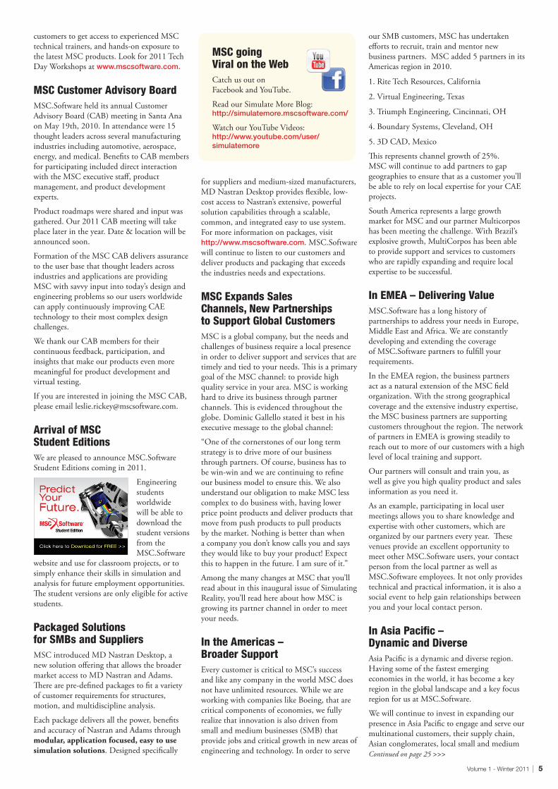
SimXpert automated GUI based parametric macro process for a complete 3D FEM bellows model generation
Exhaust Gas Recirculation (EGR) system and EGR pipe, mode and frequency analysis using the FEM
Flexible metal hose components and final assembly (thin-walled metal bellows is the critical component for being leak-tight, durability and corrosion)
Validation of FEM model using Road Load Acquired (low Frequency motion) Data Input – Time-history 6DOF engine motion, Output – Time-history 6DOF Flex relative motion(The plot above shows just one DOF (axial) but similarly validated for other 5DOF)

10 | MSC.Software
CUSTOMER SPOTLIGHT
jection seats must work perfectly every time they are used in an enormously wide range of altitudes, aircraft motion profiles, wind conditions and pilot weights while at the same time taking manufacturing variation into account. Physical testing of course plays a pivotal role in ejection seat design but time, cost and safety limit the number of situations that can be tested to far fewer than the number of potential ejection scenarios. Analysts at the Naval Surface Warfare Center (NSWC) at Indian Head, Maryland, and the 45th Space Wing at Patrick Air Force Base, Florida, have developed a model of an ejection seat using MSC Adams rigid body simulation software. During the model’s initial 5-year joint-force development process, Adams was the first professional dynamics software used to completely model the complex physics involved in the deployment of an ejection seat.
“The Adams model has provided a significantly higher level of understanding of ejection seat deployment,” said Sean Stapf, Ejection Seat & Rocketry Analyst for the 45thSpace Wing. “We have used the model to investigate incidents where the ejection scenarios were not understood until they were reproduced in the simulation, to analyze the effect of possible manufacturing variations and guide a number of design improvements such as arm and leg restraints that were recently added to ejection seats. The ability to accurately simulate their complete operation has revolutionized our ability to improve ejection seat performance and safety.”
Physical testing essential but not sufficientThe CKU-5 rocket catapult is used with the ACES II ejection seat as the aircrew escape ejection system on A-10, F-15, F-16, F-22, B-1 and B-2 aircraft. Ejection seat testing at both the component and full-assembly level are the primary tools for the conceptual design and validation of ejection seat performance. For example, sled testing can be used to capture important data such as the trajectory of the seat and resulting accelerations on the manikin representing the crewmember. However, the wide range of possible ejection seat operation scenarios and the technology and cost limitations of physical testing equipment mean that it is only possible to test a tiny fraction of the possible ejection seat deployment scenarios.
Simulation of an ejection seat is extremely challenging because of the breadth and complexity of the different physical processes that must be accounted for in order to provide accurate results. The most difficult aspects of the simulation challenge include:
• the complex potential motion of the aircraft such as rolling and pitching during the ejection
• accounting for the effects of the multiple rocket thrusters including: - the catapult rocket that pushes the
ejection seat up the spine of the cockpit
- a sustainer rocket that provides an additional 200 feet or so of lift so that the ejection seat can clear the aircraft tail at high speeds and gain safe recovery at low altitudes
- if there are two crewmembers ejecting, divergence thrusters are used to move the two seats away from each other
- a stabilizer thruster fires to offset forward or backward pitching motion
- another rocket fires to deploy the parachute
- special purpose energetics are incorporated in some seats to perform functions such as separating the seat from the crewperson, disconnecting drogue chutes, spreading or un-reefing parachute canopies, and removing night vision gear
• understanding the mechanics of the rollers attached to the seats that run in the aircraft tracks behind the seat during the ejection
• incorporating the multiple stages of the ejection process including ejection, extraction and inflation of the parachute, separation of the crewmember from the seat, etc.
• determining the effects of wind conditions including crosswinds, headwinds, aircraft carrier motion, etc. Continued on page 29 >>>
Adams Extends the Military’s Ability to Improve Ejection Performance and Safety
E
PATRICK AIR FORCE BASE
By Sean StaphPatrick Air Force Base, 45th Space Wing

When mission success is critical, you need to understand what you’re designing before it gets built. Multidiscipline Simulation gets you there.
Dynamic operating environments, performance requirements,
and safety challenges are causing defense organizations to
find new ways of developing and testing systems within the
specified budget and time constrainsts. Multidiscipline
Simulation software and services solutions from
MSC.Software makes this possible.
Our market-leading solutions such as MSC Nastran,
MD Nastran, Adams, Marc, Patran, SimXpert, SimManager,
and more, empower your engineering team to design, test,
and improve the complete functional performance of your
products faster and more economically than ever before.
And, our flexible, token-based MSC.Masterkey license system
gives you access to the tools you need, when you need them.
Discover how you can reduce product development time and cost.
Visit www.mscsoftware.comor call us today at 1.714.540.8900.
C
M
Y
CM
MY
CY
CMY
K
AD_Corp2-MissionSuccess_A4.pdf 1 2/28/11 3:33 PM

12 | MSC.Software
By Joe Satkunananthan Manager, Global Services Post Sales Support Americas, MSC.Software
How to Perform Faster Nonlinear Simulations with MarcDo you know that in Marc 2010, Parallel Solver technology is enhanced with new parallel solvers? • PardisoParallelSolver(solver11)–SharedMemory(SMP)
Windows32/64&Linux32/64• MUMPSParallelSolver(solver12)–DistributedMemory(DMP)
Windows32/64&Linux32/64• CASIIterativeSolver(solver9)inconjunctionwithDomain
Decomposition(DDM)–All• PardisoandMumpsDirectSolverinconjunctionwithDDM
Why is it better?
• FastPerformance• Allowlargermodelsormoredesignsimulationingiventime• UtilizedMulti-corearchitectureofmoderncomputerchips
How can one specify the parallel option for these solvers?
WhenchoosingPardisoSolver(solver11):run_marc–jjobname–nthreadntxWherentxisthenumberofthreads
WhenchoosingMUMPSparallelsolver(solver12):run_marc–jjobname–nsolvernsxWherensxisthenumberofprocessors
WhenusingMUMPSparallelsolverinadistributedenvironmentoverseveralprocessors;eachofwhichhasmultipleCPUs/cores:run_marc–jobname–nsolvernsx–nthreadntxWherensxisthenumberofprocessorsandntxtotalnumberofprocessors
WhenusingCASIiterativesolver(solver9)withDDM:run_marc–jjobname–npsndx
Do you know that in Marc 2010, contact accuracy is enhanced with the Segment-to-Segment Contact Algorithm?• 2-D&3-Dforlinearandquadraticelements• Improvedaccuracy• Currentlysmalldeformation• Currentlynofriction
MSC.Software TEch TIPS
Marc
How was it done previous to Marc 2010? NodetoSegment
How to choose the Segment-to-Segment option?
InMentat2010,JOBS–PROPERTIES–CONTACTCONTROLS–METHOD
WhyistheSegment-to–SegmentalgorithmbetterthanNode–to-Segmentalgorithm?Improvedaccuracyespeciallywithhigherorder
elements(10nodetetrahedralelements)
Node – to – Segment
Node – to – Segment
Example 1: Two bodies glued together.
Example 2: Concentric Cylinders Interference Fit
Node – to – Segment
Segment – to – Segment

Volume 1 - Winter 2011 | 13
Adams By Walter Daniel Sr. Technical Representative MSC.Software
Adams/Solver C++ the Default with 2010
WithAdams2010thedefaultSolverisnowtheC++version.
TheFORTRANSolverhadbeenthedefaultthroughAdams2008r1.Mostuserswon’tnoticethechangesowhyisthisnews?TheshortansweristhatmanynewerSolverfeaturesareintheC++versiononly.
TwonewerintegratorsintheC++solverareHHTandNewmark.HHT(Hilber,Hughes,andTaylor)isbasedonNewmarkandthesetechniquesevolvedfromstructuraldynamicsmethods.Thesetwointegratorsfocusonspeed.HHTandNewmarkworkwellformodelswithmanyparts(e.g.,windturbines)andmanycontacts(e.g.,trackedvehicles).ChecktheINTEGRATORstatementintheC++solverdocumentationformoredetails.
TheC++versionofAdams/Solvercanrunmultiplethreads.ThiscapabilityiscalledSharedMemoryParallel(SMP)processingbecauseallthememoryisononecomputer.Theresultsarehighlymodel-dependentbutcanincreasesolutionspeed10%to50%ormore.UsetheSearchtabintheAdamsdocumentationtosearchfortheterm“threads”tofindmoreinformationaboutsettingsandprocess.
DidyouknowthattheC++Solverhasarun-timefunctionfortrackinghowmanysecondsofCPUtimehavebeenused?ThefunctionissimplyCPUwithnoarguments.OnesimpleusewouldbetocreateanAdams/ViewfunctionmeasurewithF(time)=CPUsothatyoucanseehowlongtheruntookevenifyouaren’twatchingthescreen.Infact,youcoulduseaDesignObjectivetocapturetheLastValueoftheCPUmeasureandrecorditasaResponseinanAdams/Insightstudy!AnothersimpleapplicationistoaddasensorwiththeCPUfunction;whenthesensordetectsthatacertainnumberofCPUsecondshavebeenusedthesensorendsthesimulation.Thistechniqueisusefulforautomaticallyskippingfailurecasesinamultiple-runstudy.
Adams/View Integrator DebuggerDidyouknowthatAdams/Viewhasabuilt-inintegratordebuggerthatallowsyouseewhatishappeninginsidetheSolver?ManyexperiencedusersknowabouttheAdams/SolvertoolDEBUG/EPRINT,buttheresultingoutputisaratherlargetextfile.TheAdams/Viewdebuggerpresentssimilarinformationintabularandgraphicalformat.
YoumustberunningtheInternalSolverwithAdams/Viewtousethedebugger.GotoSettings->Solver->DebuggingandsettheradiobuttontoOn.ThedefaultistodisplaytheTableofErrorinmodelentities.CheckingtheMoreboxwillpresentmoreoptions.
Thetableshowsthemodelelementsthatcontributethemosterrortotheapproximatesolution.Ifamodelfailswithajointcausingmostoftheerror,itislikelythatthejointisaboutto“lockup.”Similarly,ifasingle-componentforcewithauserfunctioncausesmostoftheerrorbeforeintegrationfailure,it’spossiblethatthefunctioniscomingclosetodividingbyzero.
OneoftheoptionsexposedbytheMoreboxarestripchartsforintegrationstepsize,iterationsperstep,andpredictionpolynomialorder.Inthisplotthe
integrationstepsizestartedoffsmall(HINIT),quicklyincreasedtothemaximumstepsize(HMAX),andstayedatthemaximumexceptforasmalldropduringtherun.Forthismodelthestripchartshowsthattheintegratorishavingnoissuesatallwiththemodel.
IntheAdams/ViewhelpthereismoreinformationinthetopicDebuggingYourModel->UsingtheSimulationDebugger.ForadetaileddescriptionofwhatisdisplayedinthetablegototheAdams/SolverdocumentationfortheDEBUGcommand.
Patran By Huy Pham Technical Representative, Global Services Post Sales Support Americas, MSC.Software
Common Patran Questions Answered
New Features in Patran 2010:MSCNastranusersoftencallTechnicalSupportsaying,“WheredoesPatranputmy.bdf,.f06,and.xdb?HowdoIcontrolthis?”Allof
thesejobfilesgointheworkingdirectory.Previously,thiswasseteitherwiththe“StartIn”directoryoftheshortcutforWindowsusers,orthedirectorythatthep3orpatrancommandwasinvokedinUnix/Linux.
InPatran2010,there’sanoptionthat’sonbydefaultthatallowstheworkingdirectorytobesetasthesamedirectoryasthedatabasedirectory.Somemayprefertheoldbehavior.Ifso,uncheckthe“SetWorkingDirectorytoDatabaseLocation”toggleontheNewDatabaseMenu.
AnothernewfeatureaddedinPatran2010iswebbasedhelp.Theonlinehelpisaseparatedownloadandinstallation.It’sdonethiswaytokeepfilesizesdown.ThismeansnewMSCPatranusersoftenhittheF1key,onlytofinditdoesn’tdoanythingsincetheonlinehelpprobablywasn’tinstalled.Inpreviousreleases,thismeanthavingtorevisittheSDC,andthendownloading,(andthenwaiting),andtheninstallingthisdownload.(More
waiting.)In2010,userscansetanenvironmentvariable:P3_HELP_DIRECTORY=http://www.mscsoftware.com/patran/patran_2010/html_patran/.Oncethisvariableisset,hittingtheF1keywillbringuptheMSCPatranhelppagesevenifitisn’tinstalled.MSCPatranwillgrabtheinformationitneedsofftheMSCwebsite.Thisprovidesanumberofadvantages:
• Nowaitingforadownloadandinstallation,orhavingtouninstallitlaterfornewreleasesofMSCPatran.
• Theuserwillalwayshavethelatest,uptodatedocumentation.
http://www.mscsoftware.com/ patran/patran_2010/html_patran/

14 | MSC.Software
TECHNOLOGY MATTERS
By Fan Wenjie Center for Space Science and Application, Chinese Academy of Sciences, Beijing, 100190
Dynamic property of antenna plays an important role to all satellites. Antenna is a typical electromechanical product and dynamic property is important to the electronic property. The beam width of antenna is narrow, so the demand of directional precision is very high. Stiffness of antenna structure must be high enough for the directional precision. Also, the strength must have a margin. This article mainly researches a composite material antenna, analyzing the natural frequency, natural modal and frequency response. MSC Nastran was used as the finite element solution.
Antenna StructureThe reflection surface of antenna is a sandwich construction. A sandwich panel is a layered structure consisting of a thin facing material, or skin, bonded to either side of a thicker, low density, core. It is a type of stresses-skin construction with the skins carrying the major applied loads, in-plane loads and flat-wise bending moments. The honeycomb core is made of Al-alloy and the face sheets are made of carbon fiber. The sandwich construction has many advantages: mass saving with respect to conventional structures, high specific stiffness, and good fatigue properties. Figure 1 and 2 show the CAD (Computer Aided Design) model and the FEM (Finite Element Method) model. In the FEM model, the face sheets are modeled in shell element.
Dynamic Response Analysis of Composite Material Spaceborne Antenna
CENTER FOR SPACE SCIENCE & APPLICATION, CHINESE ACADEMY OF SCIENCES, BEIjING
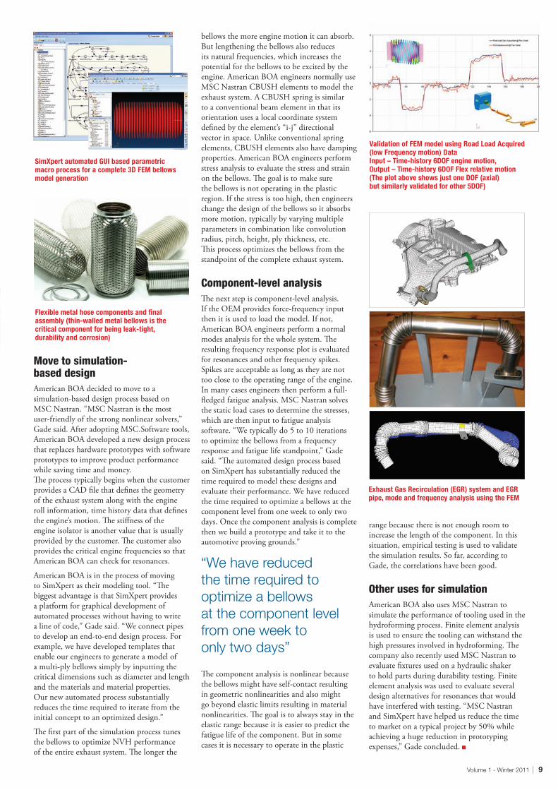
Modal AnalysisModal analysis is the foundation of the dynamic analysis and the natural frequency and the modal shape. The first and second natural frequency of antenna is 73Hz and 80Hz. The first modal shape is local y-directional bending vibration of waveguide shown in Figure 3 and the second modal shape is whole x-directional oscillation shown in Figure 4.
Frequency response analysisX-directional and y-directional frequency response analysis of antenna is done, the acceleration response is obtained, and the strength of waveguide is computed.
Frequency x-directional sine vibration The modal damping ratio is 0.025 from experiment data. Figure 6 shows the x-directional acceleration response curve and the x-directional acceleration of Point 1 is 83g (the experiment data is 82.7g).
Y-direction sine vibrationModal damping ratio is 0.04 from experiment data. Figure 7 shows the x-directional acceleration response contour and the maximum acceleration is 167g located in the middle of waveguide. The response of point 1 is 69g (the experiment data is 58.2g).
Figure 1: CAD model of antenna Figure 2: FEM model of antenna
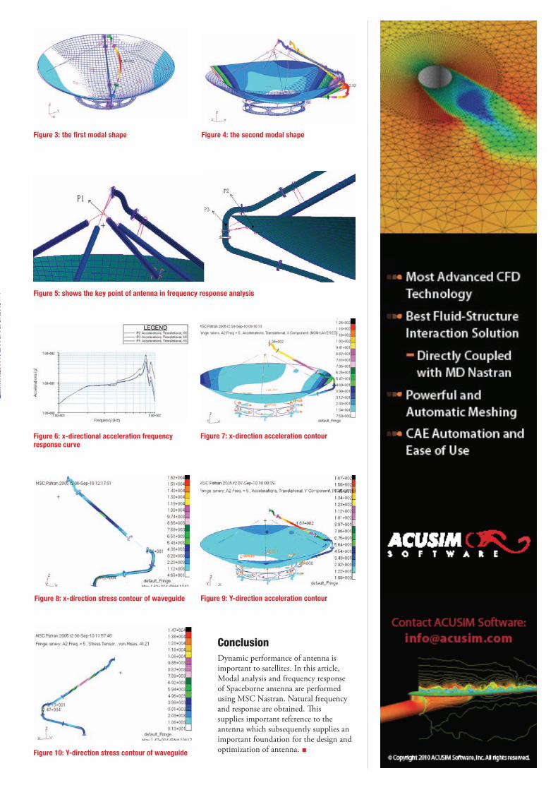
ConclusionDynamic performance of antenna is important to satellites. In this article, Modal analysis and frequency response of Spaceborne antenna are performed using MSC Nastran. Natural frequency and response are obtained. This supplies important reference to the antenna which subsequently supplies an important foundation for the design and optimization of antenna.
Figure 3: the first modal shape
Figure 5: shows the key point of antenna in frequency response analysis
Figure 4: the second modal shape
Figure 9: Y-direction acceleration contour
Figure 10: Y-direction stress contour of waveguide
Figure 6: x-directional acceleration frequency response curve
Figure 7: x-direction acceleration contour
Figure 8: x-direction stress contour of waveguide

16 | MSC.Software
TECHNOLOGY MATTERS
By Christina ExnerAchates Power
AbstractAchates Power, Inc. is developing a lightweight, low-emissions and low fuel consumption two-stroke, opposed-piston diesel engine designed as a modular and scalable mechanism termed A40. Achates Power places heavy emphasis on modeling and simulation through state-of-the-art analytical tools and methods.
Within the structural dynamic analysis arena, the focus is on overall dynamics, such as torsional and bending vibrations, including torsional vibration damper (TVD) and flywheel layouts, as well as (hydrodynamic) bearing analysis. The emphasis is on identifying areas of conceptual, structural and dynamic improvement with regard to overall dimensions and weight. A hybrid approach is utilized, thus combining the advantages of multi-body simulation (MBS) and finite element analysis (FEA).
This paper specifically discusses the application of structural dynamic simulation based on MSC Adams software with regard to:
• The influence of the engine block support structure sensitivity on bearing loads: The A40 opposed piston engine has comparably small main bearing loads relative to the peak cylinder pressure (PCP) due to the partial cancellation of forces during the opposed motion of the reciprocating masses. This allows for aggressive weight optimization of the support structure while maintaining sufficient bearing support.
• The mitigation of gear resonances: The two crankshafts of the mechanism are timed by a set of gears. During testing, a gear resonance within the operating speed range was detected that induced a substantial load on the neighboring main bearings. A sensitivity study was performed to find the optimum solution for removing the resonance from the speed range.
IntroductionA world with finite supplies of petroleum and limits on carbon dioxide emissions demands fundamentally better engines with increased fuel efficiency. Compared to conventional engines currently on the market, opposed piston diesel engines have a thermodynamic advantage (no heat rejection into cylinder heads) and the potential for lower friction (no valve-train and low piston side loads) leading to substantially better fuel efficiency. A further advantage of this engine architecture is the decreased cost due to a lower parts count while maintaining ordinary manufacturing methods. Opposed-piston engines, besides their thermodynamic advantages, naturally have a weight advantage over conventional engine architectures due to being a two-stroke engine and due to the lower complexity of the engine
mechanism. To further reduce weight, while maintaining adequate durability, advanced analysis methods are required that combine multi-body simulation (MBS), finite element analysis (FEA), optimization and fatigue analysis.
Adams-based FEV Engine has been used as the MBS software of choice to reduce the number of degrees of freedom (DOFs) of core components like the crankshaft and engine block while retaining nearly complete structural information. This approach allows for reasonable runtimes in order to explore a large range of operating conditions while maintaining full component interaction.
ModelIn an opposed-piston engine, two facing pistons in a single cylinder come together at top dead center and move apart under combustion.
The opposed-piston A40 engine architecture incorporates an innovative mechanism to drive the pistons. The two pistons are being connected to two crankshafts via six connecting rods per cylinder with the intent to
create a purely axial piston motion and ideally no piston side forces. The connecting rods are in permanent tension and thus, lead to main bearing reaction forces feeding into the block rather than the bearing cap. In addition, the nature of the A40 opposed piston motion leads to partial cancellation of the combustion forces. These two effects allow for a lightweight support structure. The two crankshafts are connected via a gear train and a single flywheel is mounted on the output shaft. Figure 1 illustrates one view of the A40 4-cylinder cranktrain model in the flexible support structure in addition to a rear view of the gear train. The mechanism may appear complex at first sight but, in actuality, it is composed of approximately half the number of components of a conventional engine. The results demonstrated in this work will focus on a 4-cylinder version of the Achates Power A40 engine.
With the different levels of refinement offered in the Adams software, the cranktrain was moved from a purely kinematic component model with rigid components and constraint bearings into a fully flexible model supported Continued on page 30 >>>
ACHATES POWERStructural Dynamic Analysis of an Opposed-Piston Engine with Flexible Support


18 | MSC.Software
TECHNOLOGY MATTERS
By Amer El-Rez and Mathieu LussierOptimec Consultants
ased in the Greater Montreal area in Quebec, Canada, Optimec Consultants is an advanced engineering consulting firm offering Computer Assisted Engineering (CAE) services and complete Finite Element Analysis (FEA) solutions as well as being a certified Reseller of the MSC.Software product line.
For the past year, major efforts have been directed towards maximizing the potential uses of templates for building and analysing FEA models. Templates are powerful macros that allow automation and improve productivity. Template building capability is a very promising application of the new and modern pre and post processing software developed by MSC.Software’s SimXpert. The goal of developing templates is to use them internally and to offer unmatchable personalized MSC.Software solutions to existing clients and to new industries looking to implement the Finite Element Method in their design process. This article will present four key templates that have been developed specifically for the large machinery industry, as well as review the work in progress and future developments.
SimXpert Template Builder Workspace permits the creation of templates aimed at automating repetitive processes. Building templates can be done using the provided actions library or via macro recording. Specific scripts can also be coded using Python programming language. SimXpert Template Builder’s main advantage over its competitors is its ease of use and straightforward interface (prior to this project, the author had no previous experience with neither Python programming nor automating). Consequently, developing templates that address specific FEA needs thus becomes
the best and simplest way to implement best practices and proven methods across a company.
2D Properties Creation TemplateSome machinery industries require the analysis of large models comprised of a mix of steel frames and beams assembled together. Each component is a welded assembly of sheet metal plates of different thicknesses. The plates are modeled as 2D shell elements with a property for each thickness. While simple, the creation of these properties is repetitive and error prone. A template was developed to automate the creation of the 2D properties with a CVS input file of the thicknesses. Figure 1 shows a typical model that requires thirty (30) different properties. A CVS input file of the different thicknesses is used and the shell properties are created automatically with the corresponding material and in the right unit system.
Automated Paper Rolls Creation for the Pulp & Paper IndustryRolls are used in the Pulp & Paper (P&P) industry for drying, pressing and transporting paper or felt throughout the manufacturing cycle. These rolls tend to be heavy and long and need to be accounted for. A typical P&P model has between 15 and 20 rolls. Each roll is different in cross-section, weight and length. Also, each roll sustains loads from the nipping of the paper between two rolls or the tension created by transporting the paper or the felt. Different 1D properties are necessary to model each roll appropriately. Moreover, the application region of the load is roll specific. The creation of the different properties, the application of the load and the proper location of the roll can take up to 30 minutes for each roll. A template was developed that allows the
creation of each roll with simple inputs. The roll is then created within seconds (figure 2).
General Purpose Non-Structural Component (concentrated masses) Modeling Template Not all components of a large machinery model are modeled in details. Non-structural components (such as gears, brackets, electronic boxes) are usually added as concentrated masses (CONM2). These masses are connected to the rest of the model via Rigid Body Elements (RBE2 or RBE3). One hundred masses can be added for a typical model. The creation of these elements as well as the connection to their corresponding area of attachment is tedious and very long. Also, since SimXpert does not offer the creation of 0D properties, the verification of each mass is extremely time consuming. The process of creation and verification of all the generated masses can take 8 to 10 hours. The risk of human error is also apparent. A template was developed to create efficiently the non-structural masses and practically eliminate the need for in depth verification. The process creates the concentrated mass element and attaches it to the nodes of a selected surface within a certain inputted radius. Custom attributes added to the mass element allow quick visual verification of the component’s name and weight (figure 3 & 4).
2D Shell Thickness Modification TemplateCertain machinery operates in high humidity levels (P&P, mining, etc.). Over the years, important rust accumulation on the metal plates will require a revision of the stress levels of the machinery. Rust level is usually provided
OPTIMEC CONSULTANTS
Building Large FEA models efficiently with Templates
B

Volume 1 - Winter 2011 | 19
as a percentage of thickness loss from on-site measurements and varies for different locations on a large machine. With the typical thirty different thicknesses of a large machinery model and about five to ten rust levels to be taken into account, a ‘rusted’ model can require about 120 different shell properties with each specific application region. This process is extremely long and error prone. Twenty-four hours are usually necessary to update a model to its rusted state. A template was developed that requires the selection of elements and the rust percentage to be applied. With this information, it automatically calculates new thicknesses, creates the new shell properties and applies the new properties to the selected elements (figure 5 & 6).
Future ProjectsTemplates are currently being developed for nonlinear analysis modeling (drop testing, top loading, plastic and rubber projects) in response to specific customer interests. SimXpert Template Builder’s ability to access different software and to create different files and formats is also being studied for shortening post-processing and report building time.
With the implementation of the Finite Element Method in new industries with limited or developing FEA knowledge, the need to offer customized and ‘client-oriented’ software solutions becomes crucial. Templating right and proven methods will not only benefit the everyday stress engineer but will also permit the use of FEA by the larger
engineering community.
The author would like to thank the MSC team for their great support and continuous help throughout the development of these and future projects. Specifically, we thank immensely our local friendly Application Engineer and SimXpert Template Aficionado, Dominick Lauzon. He offered valuable help, support and training. We thank also all the MSC Forum members for their input.
If you have any questions or comments, feel free to contact us. Contact:OptimecConsultantsInc.2994,BoulDagenaisO.,Laval(Qc)Can,H7P1T1Tel:450.937.1974•Fax:[email protected] www.optimec.ca
Figure 1: A typical large machinery model with thirty (30) different 2D properties
Figure 2: A few inputs are needed to create all the required information to generate a P&P roll at the right location with its corresponding loadings
Figure 3: Two non-structural masses are created quickly by simply inputting the locations (points), the surface and the radius of attachment as well as the mass attributes and its corresponding weight
Figure 4: The template can be repeated until the radius of attachment is representative. Custom attributes added to the mass element allow quick visual verification of each element
Figure 5: Typical beam has fourteen different thicknesses. High humidity levels caused a general 25% of thickness reduction over the years.
Figure 6: The selected elements are updated with their new ‘rusted’ properties without affecting the rest of the model

20 | MSC.Software
PARTNER SHOWCASE
ApproachThe approach which we will use is centered around the importance of capturing as-molded part conditions, and importing these properties into a typical FEA solver for loads analysis.
To do this, we will employ two commercially available FE codes, for molding simulation we will use Moldex3D, for the quasi-static loads simulation we will use MSC Marc. Both are robust non linear codes proven in commercial analysis of thermoplastic parts.
Part descriptionFigure 1 shows a sample part created to illustrate the case study:
Our sample part measures 10” x 6” x 3” deep. The perimeter walls are uniformly .13 thick, with the ribs measuring .10 thick. The material is 30% glass filled polypropylene.
As Molded ConditionsThere are a number of factors that are of interest to the analyst which occur during the molding of a typical thermoplastic component, and these factors can and do influence the material priorities and field behavior of the parts:
1. Deformed mesh. The tool designer is aware that plastic materials shrink, and attempts to provide a correction factor (shrink factor) into the part geometry to compensate for the inevitable shrink. The exact amount of shrink to apply can sometimes be difficult to determine, as this factor is not only geometry (part) dependent, but also depends
on the gate type and location as well. Running a mold flow analysis with proper PVT material curves will provide an accurate measure of the actual material shrink. The deformed mesh can then be exported to provide an exact representation of the as molded wall thicknesses and specific feature dimensions, which is much more accurate than just applying generalized scale factor in the flow and transverse flow direction.
2. Thermal strains. Differential cooling of the part can lead to thermally induced strains that contribute to distortions in the final geometry.
3. Residual stress. Two factors can lead to residual stresses in the molded part, thermally induced stresses, and flow induced stresses. Both result in build up of stress in the finished part. These stresses should be considered in any downstream structural analysis of the part performance, although the values are usually quite low. They can and do create conditions where temperature cycling, sterilization, and long term exposure create dimensional variances in the part.
4. Weld lines. Intersecting melt fronts create weld and meld lines in any part, these areas have different structural material proprieties than homogenous material, and if these weld lines occur in areas that carry load, we have to accommodate these reduced properties in any load bearing calculations.
5. Flow line orientation. Particularly for filled materials, this is one of the most critical of all criteria, and the one most often compromised. The mechanical properties of thermoplastics is highly dependent on the
flow orientation of the plastic as it enters the mold cavity, and also dependent on the part shape to determine flow line orientation. For glass filled materials, this means the materials are highly anisotropic, and using generalized mechanical properties for FEA is a dangerous assumption. This case study shall focus on this aspect of the as-molded part to illustrate the issues at hand. Figure 2 illustrates the high variability for a glass filled material- the top shows an actual section of a molded part, the bottom shows the predicted results from the simulation.
Mold Flow SimulationWe are considering a sample part as shown in Figure 1 molded with a 30% glass filled polypropylene polymer. We have selected a gate location to illustrate the appearance of weld lines, and to show the flow behavior of the plastic as it enters the cavity.
Importing “As Molded” Plastic Part Conditions into CAE toolsInnova EngineeringBy John CoggerInnova Engineering
Figure 1: Solid model of case study molded part.

Volume 1 - Winter 2011 | 21
We have set up a simple mold flow simulation using approximately 500,000 full 3D elements. It is critical to use full fidelity 3D elements for this type of simulation, the typical CAD plug in type of solver using a mid-plane model and 2D shell elements will not capture the flow line behavior properly. The simulation included filling, packing, cooling, and warp loadcases.
After our filling simulation is complete, we can open our post processor and view the fiber origination of the 30% glass filled material. Figure 5 shows the entire part with the directional ordination of the fibers highlighted. Very strong axial orientation is seen at the sides, and as the plastic “turns the corner” in the outside radii, the directionality of the fibers changes as a result of the flow dependency and geometry influence.
What we are seeing in figures 5 and 6 are fibers represented by directional arrows, or vectors, corresponding to the flow induced orientation. The darker the color, the more directional orientation, the blue represents randomized fibers.
Much can be learned just from the visualization of the directionality. Designers can consider the areas of the part that will see load, and they can ensure the load is as close to parallel to the fiber direction as possible, as this is where the material has the greatest strength. The sample can be of course considered for the weld liens, we want to be sure the weld lines are not located in a load path if possible.
Beyond these visualization techniques, we must understand the structural capacity of the material in the as molded condition. The flow lines in this example are so nicely orientated that we could consider the properties to be orthotropic, and this would be the case for the majority of the part, but we will use anisotropic properties so as to capture the randomized areas that do not exhibit cleanly orthotropic properties. Examples of these areas may be seen in figures 5 and 6 as noted in blue.
As a reference, isotropic properties are normally used on FEA of plastics. This considers the mechanical properties to be the same in all directions of orientation. Orthotropic considers the properties to be different in X, Y, and Z, and anisotropy considers the mechanical
properties to be different in all directions, the most comprehensive material property model available. This is the model we shall use.
Now that we have identified the flow line orientation through a comprehensive 3D mold flow simulation, we can now take steps to export these properties to our downstream FEA solver, capturing the as-molded condition as anisotropic material properties, and mapping these material orientations to the new FE mesh.
Structural FEA SimulationTo set the stage for a robust comparison, we intend to create two identical FE part models. The first will use the most commonly used method by plastics analysts, which is to use isotropic material properties. This can be published data, as is often the case, and this usually means Young’s’ modulus and Poissons ratio if a linear elastic loadcase is anticipated. Sometime, the FE analyst is keenly aware of the pitfalls of using linear elastic analysis for plastics, and will instead perform physical testing to develop elastic-plastic stress strain curves. In either case, the result is usually the assumption that the material behavior is isotropic.
The second model we will run will use the exported material properties as determined in the previous mold flow study, and will take full advantage of the flow orientation of the glass fibers. We will load the parts identically, and examine the results.
To start, we will create a mesh in Marc which will be imported into the mold flow solver for mesh mapping. Once imported, the fiber orientation results are mapped to the new mesh. This mesh is now brought back into the Marc non-linear solver, and standard boundary conditions are applied. Our problem in both cases is to be displacement controlled, e.g. we will apply a displacement of .12/inches to the center of both parts, and solve for the maximum stress in each part.
Figure 8 shows the mesh of the as-molded part. We can clearly see the mapping has taken place, each color gradient represent some different anisotropic material value depending on fiber orientation. There are some 1600+ different mechanical property values differing as a result of the flow induced orientation.
ResultsBoundary conditions were established on the short side segments, and the load applied in the center as described earlier. First, we will look at the typical isotropic material model results.
Figure 9 shows the peak Von Mises stress when the part is loaded without consideration for the as molded material condition. In other words, we do not take into account the directionality of the fiber orientation. We show a peak stress value of 70 Mpa. This particular material has a yield value of 56 Mpa, so this part is well on its way to failure, as this analysis indicates Continued on page 31 >>>
Figure 2: Flow orientation of glass fibers
Figure 4: Filling animation
Figure 7: Fiber orientation- runner to gate location
Figure 5: Visualization of fiber orientation
Figure 8: Fiber orientation- mesh mapping
Figure 3: Mold filling simulation
Figure 6: Fiber orientation- close up

22 | MSC.Software
PARTNER SHOWCASE
By Patrick McNally VI-Grade
Simulation is ChangingSimulation is used by leading companies to understand a design before the first prototype is built. In the automotive industry, simulation is used to improve performance, safety, and vehicle durability. The results are reduced time to market, decreased manufacturing and testing costs, and improved customer satisfaction. But the industry continues to demand more.
One demand is to support the simulation of more complex automobiles with more automatic controls which influence new powertrains, chassis dynamics, and safety. Suppliers are asked to deliver sophisticated designs, especially for hybrid and electric
vehicles, increasing the importance of vehicle integration. How will simulation tools meet these challenges?
Additionally, with the pressure to deliver more exciting products faster, companies continue to look for simulation tools that will provide more design insight earlier in the design process. Physical laws can be simulated – but can engineers really describe an emotional experience from “exciting products” through simulations?
Five years ago, leading vehicle dynamics experts formed VI-grade as a spin-off company from MSC.Software. We have focused on improving and supporting the Adams vertical products and creating new products like
VI-CarRealTime, which is the key product we have developed to address these current issues of simulation.
Bringing Simulation Models TogetherFor many years, integration of the automotive supply chain has been important and virtual models have played a strong role in advancing supply chain collaboration. Referring to Figure 1, the system engineering process starts with the entire vehicle, through the specification of performance, comfort, safety, and other targets. Requirements are broken down to the subsystem and component level in a way that each piece shares a responsibility to meet the overall system level target. MSC, VI-grade, and many other companies in the virtual prototyping business provide tools to develop virtual models and methods to integrate these models into subsystem and system level virtual prototypes to prove out a design before it is built. The promise is there, but our customers tell us there are two key issues.
First, different vehicle design tools are used for different tasks. Adams is a key standard for vehicle dynamics simulation, but the control systems are often developed in MATLAB. Simple alternative vehicle models are used in controls and hardware-in-the-loop environments. These different tools result in inconsistent models and a manual translation of data between vehicle representations.
Second, vehicle controllers are often developed by suppliers with a limited knowledge of the vehicle design, but these controllers have a significant influence on the overall vehicle performance, safety, and other attributes. The final controller virtual design may never
Adams Goes Real-Time, Design Integration between
Suppliers and OEMs
VI-Grade
Figure 5: VI-DriveSim dynamic motion platform photographed at the 3rd VI-grade User Conference, October, 2010

Volume 1 - Winter 2011 | 23
become integrated with the final virtual vehicle design – they come together in most cases as hardware on the test track late in the design cycle. What if there is something wrong with the controller?
Could an OEM supply a vehicle model that the suppliers could easily use, inside their own tools, without giving away proprietary design information?
VI-CarRealTime as a platform to exchange modelsVI-CarRealTime was originally developed to be used as a parametric vehicle model for conceptual design, for controls development, and for hardware-in-the-loop testing. The VI-CarRealTime model is fully compatible with Adams/Car: VI-CarRealTime uses the same database, the same events, the same roads and the same driver files.
Any vehicle with independent front suspension and independent or dependent rear suspensions can be modeled. The suspension components are idealized into kinematic and compliant curves, so that proprietary design information is protected.
Figure 2 shows some of the suspension details which are included in the vehicle model. Toe and camber curves are functions of wheel travel and applied forces and torques in compliance mode. Spring and damper components are modeled with property files containing the same nonlinear effects as the Adams models. Auxiliary roll and vertical stiffness are added for additional accuracy.
Proof that VI-CarRealTime is fast and accurate throughout the supply chainAudi needed an accurate vehicle model that their controls designers could use in the Simulink environment. Because multiple controllers were being developed, they needed a way to quickly simulate interactions between different control systems. VI-CarRealTime provided this multiple control system capability. To test the accuracy of VI-CarRealTime, Audi compared several events with Adams, including a quasi-steady-state cornering analysis for different anti-roll bar sizes as shown in Figure 3.
The VI-CarRealTime model can also be used by automotive suppliers with their controllers, active components, or test representations. An OEM provides the vehicle database, with parametric data and conceptualized suspensions, using the VI-CarRealTime database. The suppliers develop their designs with the OEM database and add their models back in before sending the database back to the OEM. The result is a faster development process and tighter integration of the overall design.
Through close collaboration with major automotive OEM’s, VI-CarRealTime code now produces accurate results for a spectrum of events on a large variety of roads, for complex new vehicle designs with a variety of vehicle controllers. Users now include automotive OEM’s and suppliers and major racing teams in Formula 1, IRL, and NASCAR.
Feel the excitement of new designsA test driver can tell you how new designs with new control systems feel when they hit the test track. But what if you could feel the result of a new design before building the real prototype vehicle? That’s where VI-DriveSim
comes in. VI-DriveSim is a driver-in-the-loop simulator built around the VI-CarRealTime model - the same vehicle dynamics model that is derived from Adams. Now, the test track is brought into the engineering office, where the “excitement” factor of new designs can be tested out before building the first hardware prototype.
Our DriveSim technology is a modernization of the old hexapod designs. Using Adams and other virtual tools in the design process, we have arrived at a new design that takes up less volume, power, and weight for the same performance as a hexapod. The concept is shown in Figure 4 and the first prototype is shown in Figure 5.
Exciting proof for a new approach to vehicle developmentFrom concept to driver-in-the-loop testing, VI-CarRealTime and VI-DriveSim are proving out a new approach to develop vehicles with integrated controllers, all based on the standard set by Adams. In conclusion, we offer three statements about the technology from our customers and partners:
“Our very first tests of the VI-grade driving simulator show an outstanding agreement between the Silverstone qualifying session and the lap time achieved on the simulator by our top driver – with just less than 0.5% time difference!”
– Alex Somerset, Technical Director of MOFAZ Racing
“The strategies for developing efficient control systems for vehicle handling and ride are becoming every day more complex and influence even the conceptual design phase… It is becoming essential to access hybrid test platforms which could provide to the driver realtime perception cues as if they come from the real vehicle. “
– Major European Automotive Manufacturer
“Many times we modify suspension components based on simulation results and we believe we have reached the best solution. Then the test driver says the car is not good and driveability is bad. This approach involves huge investments! ...In the future, we will test all of our solutions on the driving simulator before building the first prototype.”Major North American Automotive Component Manufacturer
Figure 1: OEM-Supplier Collaboration through Exchange of Virtual and Physical Models
Figure 2: Example suspension characteristics captured in a VI-CarRealTime model
Figure 3: Validation of VI-CarRealTime with Adams for Three Anti-rollbar Stiffnesses
Figure 4: VI-DriveSim motion platform design and advantages over traditional hexapod design

24 | MSC.Software
PARTNER SHOWCASE
n many cases, there is a missing link in today’s product design processes. The effect of the manufacturing process is often not taken into account, resulting in inaccurate predictions of product characteristics like durability, maximum load capacity, noise, and crash resistance.
For example, a stamping process introduces varying thicknesses and residual stresses in the parts. When stamped parts are welded together, this introduces further distortions and residual stresses in the final product. These deformations, thickness changes and residual stresses have a big impact on the strength and durability of the final product.
A solution to this problem is offered by combining the manufacturing simulation capabilities of Simufact with the CAE analysis capabilities of MSC.Software.
Simufact is an OEM partner of MSC.Software, and provides manufacturing simulation software and services, to customers worldwide. Simufact offers two specialized software packages:
Simufact.forming Simufact.forming is a simulation tool developed especially for industrial forming processes. It incorporates aspects of the previous simulation solutions, MSC.SuperForm and MSC.SuperForge from MSC.Software. Both of those technologies were integrated into a single product capable of simulating industrial forming processes, including closed-die forging, extrusion,
drawing, upsetting, bending, free forging, as well as cold, hot or warm, mechanical press, hammer or screw press operations, orbital forging and rolling processes.
Simufact.welding Simufact.welding is a simulation tool developed especially for industrial welding processes. It is based on the powerful non-linear FE technology of MSC.Software, and can be used to easily model robot driven welding processes, with multiple robots and multiple weld paths per robot. An unlimited number of parts can be welded, and a flexible definition is available to model the fixture that holds these parts during the welding operation, using clamps, bearings and springs.
By integrating Simufact.forming & Simufact.welding in the overall product design process, it is now possible to have process manufacturing simulation integrated with product design. The manufacturing simulation software allows this sophisticated technology to be used not only
by CAE experts but also by product and manufacturing process designers. The process is illustrated in Figure 1.
A case study of this integrated product design process was presented at the 12th Simufact Round Table Conference, held in Bamberg-Germany, during October 2010 (http://www.roundtable.simufact.eu/welcome.en.html).
The underlying technology that enables the connection between Simufact’s manufacturing simulation software and the CAE solutions of MSC.Software is the fact that the binary output files of Simufact.forming and Simufact.welding can be used as inputs for the follow up simulations. For example, a forming simulation in Simufact.forming will create a
Increased Design Robustness by including Forming & Welding
Simulations
I
SimufactBy Arjaan BuijkSimufact-Americas LLC
Figure 1: Integrated product design process

Volume 1 - Winter 2011 | 25
Continued from page 5 >>>
businesses as well as government and education institutions to name a few.
The optimum approach to effectively engage and service our rapidly growing customer base locally is through our extended eco-system of exclusively selected and qualified business partners.
Today, MSC.Software has an extensive network of business partners with close to 100 engineers, consultants and sales professionals dedicated to service our customers in Asia Pacific. These are a wonderful diverse mix of new and old channel partners across Asia Pacific, matching the diversity of the countries, culture as well as specific requirements.
As the year progresses, we will feature real world cases and success stories from our channel partners that will surely be of great interest to our valued customers... stay tuned.
And The Winner Is…Paperswerefoldedneatly,otherswerecrumpledup,somewerewritteninblackink,andothersinunorthodoxpurple.Eachsubmissionhadastory;eachsubmissionhadadream,somewerehopeful,andothersweresimplyrollingthedice,buttheretheylay.Abowlfullofpapers,anoceanofnames,numbers,hope,andemails.Onenameemergedfromtheseaofsubmissions,VenkataNagaPoornim!
Asanindustryleaderandinnovator,MSC.Softwarewantedtooffermoretoourcustomersatindustryrelatedtradeshows.Weallhavewalkedawayfromtradeshowswithpens,notepads,etc.Wewantedtooffermore...whatdidwegiveaway?Hope!Thisyear,MSC.SoftwareheldaraffleforaniPad.EntriesweresubmittedatselecttradeshowsinwhichMSC.Softwarewaspresent.Severalnamesweresubmitted,butthenamethatemergedwasVenkataNagaPoornim!
Congratulations to Venkata and thank you to all who submitted an entry.
ThisNewYearwillpresentnewopportunities.LookformoregiveawaysatfutureMSCEvents.
Toviewoureventscalendar,pleasevisit http://events.mscsoftware.com.
so-called t16 file, which can be read by MSC SimXpert, Mentat or Patran to extract both the geometry of the formed part as well as the residual stresses and strains.
The integrated product design process for a durability life assessment of a torque converter is shown in Figure 2. This figure is extracted from Reference 1, where the full presentation of this study can be found.
The durability of a torque converter is highly dependent on the residual stresses introduced during stamping of the parts, and during riveting of the parts to assemble the final product.
During the Forming process, stresses and thickness changes are introduced. These residual stresses must be taken into account during simulation of the Pressure cycling that occurs while operating the torque converter. The resulting stresses can then be entered into a calculation of the Durability
assessment. The results of this process are shown in Figure 3.
In summary, the capability now exists to seamlessly integrate manufacturing process simulation, performed with Simufact.forming and Simufact.welding, into the overall product design process.
For more details on Simufact.forming, visit www.simufact-americas.com.
References1. DesignRobustnessandProcessCapability
using6SigmaandSimufact.formingDr.KundingWangTagungsband12.Roundtable“SimulationinderMassivumformung”,Bamber2010Page209-220Simufactengineeringgmbh,Hamburg2010ISBN978-9813814-0-5
Figure 2: Case Study for Durability Life Assessment Methodology
Figure 3: Results for integrated durability life assessment

26 | MSC.Software
UNIVERSITY & RESEARCH
nitized Structures Group at Virginia Polytechnic Institute and State University, led by Dr. Rakesh K. Kapania (Mitchell Professor of Aerospace and Ocean Engineering), and Dr. Sameer B. Mulani, Dr. Wesley C. H. Slemp, and Davide Locatelli have been involved in development of frameworks for optimization of stiffened panels using curvilinear stiffeners and supersonic wings using curvilinear spars and ribs.
Experts predict the use of unitized structures is expected to grow exponentially by the year 2020. Research has shown that unitized structures result in a) reduced part count, manufacturing cycle time, and fabrication cost; b) added design flexibility, weight savings, inspectability, and resistance to fatigue and corrosion; c) enhanced automation, improved ergonomics and reduced work fatigue and corrosion; d) increased determinant assembly (DA) opportunities, improve fit and reduce design rework.
Innovative manufacturing techniques like Electron Beam Free Form Fabrication (EBF3), Friction Stir Welding (FSW), and Selective Laser Sintering (SLS) are additive in nature as opposed to subtractive, meaning that the material is deposited wherever necessary on the contrary to removal of unnecessary material from the structures. These techniques have created new opportunities and a much bigger design space to optimize structures of complex shapes especially aerospace vehicles without much material and energy wastage (Green Technologies). New types of pressurized non-circular fuselage structures within hybrid wing/
body vehicles that undergo complex structural load cases are not well characterized using current design databases.
A new framework, EBF3PanelOpt is being developed for design and optimization of complex multifunctional aircraft structural concepts like stiffened shells and panels. Commercial softwares, MSC Patran (geometry modeling and mesh generation), MSC Nastran (Finite Element Analysis), VisualDoc (external optimizer) and Python are integrated in EBF3PanelOpt frameworks to design stiffened panels.
The parametric geometry modeling features of Patran are critical for the successful operation of the optimization framework. Currently,
EBF3PanelOpt framework allows the user to optimize multi-sided panels with straight/curved edges having curvilinear, blade-type stiffeners under the action of uniform or non-uniform in-plane loads. The framework supports multiple load-case analysis as well as different thicknesses for pockets of plate formed by intersection of the stiffeners or uniform panel thickness. The mass of the panel is subjected to constraints on buckling, von Mises stress, and crippling or local failure of the stiffener using global optimization techniques like Particle Swarm Optimization (PSO) or gradient based optimization techniques. The orientation and curvature of stiffeners play an important role in the optimization apart from the thicknesses and
Development of Frameworks for Design Optimization of Stiffened Panels and Supersonic Wings
Virginia Tech
U
b) Buckling Mode of Optimized Panel
a) A Flat Rectangular Panel With Curvilinear Stiffeners
c) Von Mises Stress Distribution for Optimized Panel
Fig. 1: Rectangular Panel Optimization Using Curvilinear Stiffeners

Check out our on-dEmAnd wEbinArS!
Visitwww.mscsoftware.com/webcasts
Volume 1 - Winter 2011 | 27
heights of the stiffeners. Figure 1-a shows the flat rectangular optimized panel designed using EBF3PanelOpt. During the optimization of this panel, non-uniform thicknesses for panel pockets were used. In Figure 1-b, it can be seen that all panel pockets are in the process of buckling, and Figure 1-c shows the von Mises stress distribution for the applied load. Figure 2 shows an optimized cylindrical fuselage panel under multiple load-cases, von Mises stress distribution and buckling mode shape.
A tool called EBF3SSWingOpt is also in development to utilize curvilinear spars and ribs to optimize supersonic wings. In this framework, Patran, MSC Nastran, VisualDoc and MATLAB are integrated to optimize supersonic wings. EBF3SSWingOpt has the capability to optimize the wing using curvilinear spars and ribs (SpaRibs) for static aerodynamic loads against bucking and von Mises stress. Curvilinear SpaRibs redistribute the loads and changes its buckling modes as well as vibration modes so that one can control aeroelastic behavior and static behavior.
Currently, EBF3SSWingOpt uses the ‘Translation’ utility of Patran to generate SpaRibs, and it adds the optimal number of SpaRibs in the wing based upon the bounds of translation parameters given by the user.
Figure 3 shows the example of curvilinear SpaRibs inside High-Speed Civil Transport (HSCT) aircraft. This framework has the flexibility to put SpaRibs in the selected area by the user. Using this framework, Freedom Fighter’s wing is optimized; the comparison of the optimized wing with its original design is shown in Fig. 4.
The work of EBF3PanelOpt is funded under NASA Subsonic Fixed Wing Hybrid Body Technologies NRA Contract (NASA NNL08AA02C) with Ms. Karen M. Brown Taminger as the API and COTR and Richard Keith Bird as the Contract Monitor. The authors would like to thank our partners in the NRA project, Mr. David Havens, Mr. Robert J. Olliffe, and Dr. Steve Engelstad, all from Lockheed Martin Aeronautics Company of Marietta, GA, for their contribution in the present research. Unitized Structures Group at VT would like to thank Ms. Marcia S. Domack (Technical Monitor) of NASA Langley Research Center for substantial technical discussions. EBF3SSWingOpt was conducted as a subcontract from the National Institute of Aerospace, Hampton, Virginia. We would also like to thank Mr. John E. Barnes, Mr. Ryan J. Wittman and Mr. Agustin Garcia, all from Lockheed Martin Aeronautics Company for their technical inputs.
Fig. 3: Curvilinear SpaRibs for Supersonic wing
Fig. 4: EBF3SSWingOpt Design of Freedom Fighter Wing
a) HSCT Wing External Geometry
a) EBF3SSWingOpt Design
b) A Sample Internal Wing Structure for HSCT
b) Freedom Fighter Design
b) Buckling Mode of Optimized Panel
a) Cylindrical Fuselage Panel With Curvilinear Stiffeners
c) Von Mises Stress Distribution for Optimized Panel
Fig. 2: Optimization Cylindrical Fuselage Panel under Multiple Load-cases

28 | MSC.Software
UNIVERSITY & RESEARCH
The Center for Occupational Health in Automotive Manufacturing at The Ohio State UniversityMD Adams and LifeMOD were used to assess Musculoskeletal Disorder Risk during Automotive Assembly Tasks.Musculoskeletal disorders (MSDs) continue to be a common and costly problem in the manufacturing sector. The auto industry is one of several industries that have high incidence of MSDs. Find out how MD Adams & LifeMOD is providing a solution.
Look it up: http://www.mscsoftware.com/Solutions/Success-Stories/Detail.aspx?storyid=161
University of HoustonComposites Engineering and Applications Center: Valve-Shaft Assembly in Aero-derivative Gas Turbine System using Patran.In a Valve-Shaft system, aerodynamic force induced torque acts on the disk causing dynamic valve motion. The aerodynamic torque or flow-induced torque in the butterfly valve is strongly dependent on: (1) disk geometry, (2) the disk opening position, (3) the operating pressure ratio, (4) the local piping configuration, and (5) material density. What does that look like? See how Patran can model aerodynamic load and the geometry of the valve with various densities.
Look it up: http://www.mscsoftware.com/Solutions/Success-Stories/Detail.aspx?storyid=159
University of ManitobaUniversity of Manitoba Rides Adams/Car to Success.A custom full vehicle template, geometric design, engineering simulation, dynamic testing, and design/tuning parameters. There are so many factors that need to be taken into account by a Formula Team, find out how Adams/Car can help.
Look it up: http://www.mscsoftware.com/Solutions/Success-Stories/Detail.aspx?storyid=158
Pukyong National UniversityDynamic Deformation Characteristics of an Automotive AC Hose Using MSC Marc.The Computer Aided & Structural Analysis Lab at Pukyong National University has been conducting several research studies on automotive AC hoses. An automotive AC hose is one of the most important parts in an automotive vehicle. Learn how Marc’s powerful tools were used by the Computer Aided & Structural Analysis Lab at Pukyong National University.
Look it up: http://www.mscsoftware.com/Solutions/Success-Stories/Detail.aspx?storyid=157
UNIVERSITY& RESEARCHHIGHLIGHTS

Volume 1 - Winter 2011 | 29
Continued from page 10 (Patrick Air Force Base) >>> Finding the right software toolThe military has evaluated and used numerous open source and commercial software packages for evaluating various aspects of ejection seat events. The military has also written six degree of freedom codes designed specially for ejection seat simulation. Most of these codes have proven critical for pioneering the development of the ejection seats, simulating one or several aspects of an ejection event but none had met the goal of simulating the complete process until Adams was used.
The NSWC engineers began developing the Adams ejection seat model in the mid 1990s and the model was completed and validated by 2000. “We researched all of the mechanical parts of the different ejection seats used by the Navy and Air Force as well as British and Russian ejection seats in order to incorporate a complete feature set with the goal of being able to simulate any ejection seat,” Stapf said. The model handles compression of the three sets of landing gear. A simpler model that only included the aircraft fuselage would not have been able to account for situations where the crewmembers eject while the aircraft is in collision with the ground, driving into the soil
during a runway over-run, or arresting on a runway or aircraft carrier cable. The drag load from the parachute is calculated by putting masses around the parachute, expanding the chute and reporting the drag force as a function of the degree of inflation of the chute. The model calculates the dynamic response index (DRI) that indicates the potential for injury at any point in the simulation, combining it into the Air Force’s Multi-Axial Dynamic Response Criteria (MDRC). For example, a brief moment of acceleration at 15 g may be tolerated without injury by most of the crew population, but integrating a longer dwell of that same acceleration can identify the potential for a spinal injury. The model has proven the ability to evaluate a wide range of both the ejection scenario, and the variations in the man-seat system that undergoes the ejection.
Adams used to guide design processOne of the most interesting uses of the Adams model to date was in a case where several upgrades to the design of ejection seats were undertaken simultaneously. One of these changes arose because a small percentage of crew members that ejected suffered injuries due to the high-speed windblast that can exert
excessive forces on their limbs protruding from the seat. A historical approach has been to add lanyards that secure the crew members’ legs and arms as the seat is ejected. The restraints are deployed via a series of lanyards which are pulled through the seat as it moves up the rails during ejection.
At the same time that the arm and seat restraints were being developed to protect the crew as they emerge into the windblast, another design change was made to the catapult thruster to tailor the release profile of its energy. This change was made in order to avoid injuries that can occur within the aircraft; during the initial catapult phase of the ejection. Both of these changes had the effect of reducing the separation velocity and some tests of seats where both changes were implemented showed that seats did not obtain sufficient separation velocity.
Simulation was used to quantify the amount of force that was tapped off from the catapult thruster by the deployment of the lanyards. The results showed that the new thruster rockets worked well without the limb restraints and the limb restraints worked well with the old rockets. Various possible design changes were evaluated without the expense or time involved in building and testing physical prototypes. The conclusion was that the most promising solution to the problem was redesigning the restraints to use less mechanical energy. The solution was verified with physical testing and has already been deployed on many combat aircraft.
“Adams has played a major role in the substantial improvements that have been made in the performance and reliability of the ejection seats used in military aircraft over the past decade,” Stapf concluded. “The Adams model has been validated in many physical tests, giving us the confidence to rely on simulation results to evaluate and investigate incidents, determine the impact of possible manufacturing defects and guide the on-going design improvement process.”
Adams is used to address what-if scenarios in ejection seat operation.
Adams tracks the response of the human body during the ejection simulation and determines the potential for injury.
Adams generates loads on seat rollers and
channels in the seat. These loads are applied
to MSC Nastran and MSC Marc models
to determine the rail response. The Adams
model allows parametric adjustment of the rail
stiffness and damping, rail friction coefficient,
rail separation width, rail length, angle, seat roller
positions, etc.

30 | MSC.Software
Continued from page 16 (Achates Power) >>>
by hydrodynamic bearings. The Adams software conveniently allows for replacing any component with its flexible representation and thus, increasing the accuracy of the analysis.
The software combines the advantages of a general purpose, open architecture MBS code with an engine component library. Hence, it provides “push button” implementation of engine-specific components like the connecting rods, pistons and many others. As a result, the requirement of this multi-crankshaft and multiple connecting rods-per-cylinder mechanism is adequately supported within Adams.
The timing gear module has been used to model the gear train dynamics including gear contact and backlash and thus, allowing for full component interaction in the mechanism. The gear stiffness and cold backlash have been determined experimentally and provided as input to the model. Based on the gear attachment locations, material combination and temperature, the backlash under the operating temperature has been calculated. As backlash and meshing errors can cause significant impulsive excitation of the whole mechanism, it is crucial to accurately model these parameters.
ApproachA hybrid approach of MBS and FEA has been chosen for the structural dynamic analysis of the A40 mechanism. The first step of this approach determines the modal-neutral file (MNF) of the crankshaft and block based on the Craig-Bampton method [1, 2]. The method allows the selection of a subset of DOFs that are preserved during the modal reduction that can be used as interface nodes in the MBS model. For example, placing such DOFs at the bearing locations allows for convenient monitoring of bearing deflections under various engine operating conditions. The advantage behind modal reduction is the greatly reduced number of DOFs, while maintaining near complete modal (inertia and stiffness tensor) information along with the modal stress.
As a second step, the component MNFs are imported into the Adams model in order to achieve the best possible representation of the structural stiffness of the mechanism. The third step involves setting the boundary conditions, like gas pressure traces, oil viscosity and temperature which can be easily accomplished within Adams. Lastly, the MBS analysis is performed to analyze various aspects of engine dynamics: torsional and bending vibrations, the effect of torsional vibration damper (TVD) and flywheel lay-outs, as well as bearing analysis. In this scenario, particular emphasis has been placed on identifying areas of structural and dynamic improvement that would result in a reduction of overall dimensions and weight.
At Achates Power, Inc., this hybrid approach is routinely used in all stages of development
including sensitivity studies and root cause analyses. The approach is continuously being improved and refined in the area of component optimization and durability analysis. Additionally, the modal stresses and participation factors are superimposed and reverted into a stress tensor as basis for subsequent fatigue analysis (not described here).
Support Structure SensitivityIn the A40 mechanism, the port timing is generated by the respective phasing of the exhaust and intake connecting rods. The two counter-rotating crankshafts are identically symmetric and in phase. Therefore, the combustion forces are partially cancelled. As previously cited, the reverse architecture leads to main bearing forces that react to the block/crankcase rather than to the main bearing caps. These two effects allow for a lightweight support structure in relation to the PCP achieved with the Achates Power A40 engine.
Early on in testing, it became apparent that the limitations for the structure’s weight reduction would be determined by its capacity to support the crankshafts. The torsional and bending deflections of the crankshaft are a first indication for durability and noise and vibration harshness (NVH). The analysis started with a rigid block structure, which was subsequently replaced by a flexible representation.
The fully-coupled crankshaft bending results from incremental block refinements are shown in Figure 2.
As expected, the block representation has hardly any influence on the crank torsional behavior (not shown). However, the impact on the crank bending is significant. With the rigid block, a dominant 4th order excitation is observed with a resonance at 3,000 rpm. In comparison, the response of the flexible block shows all orders from one through four with the frequency content shifted. Despite the crank-bending amplitudes satisfying the Achates Power requirements, a higher block stiffness would further reduce crank-bending. Hence, the block stiffness was artificially increased by 20 percent to demonstrate the improvement (see Figure 2).
In addition to investigating the effect of the block stiffness, the method can also be used to guide the design toward local stiffness improvements while keeping the weight down.
Gear Resonance MitigationDuring the early A40 4-cylinder mechanism testing, a gear train noise/resonance was observed. Although this particular engine was only instrumented with two strain gage sensors, the measured gear train resonance has been qualitatively reproduced with the Adams/Engine model. The result is shown in Fig. 3.
The Adams model has subsequently been used to perform an extensive parameter study
to find the root cause and solutions to the observed gear resonance. From the many ideas of how to mitigate the gear resonance, only some selected results are presented here. The potential solutions are divided into three categories:
1. No or minor impact on the mechanism design
2. Medium impact on the mechanism design
3. Major impact on the mechanism design
The solutions in the first category include, among others, the reduction of gear backlash and flywheel inertia. From a tolerance and manufacturability standpoint, the backlash could be reduced to as low as 40 percent of the current design backlash leading to a bearing load reduction of only 20 percent which is deemed insufficient. The reduction of the flywheel inertia to 50 percent of its original value, or a complete removal of the flywheel (zero inertia), has very little if any impact on the resonance characteristics. Interestingly, the dynamic study shows that the engine could be run entirely without flywheel which would save 13.7 kg in the overall engine weight.
In the second category, two solutions involving architectural changes seem promising: moving the power-take-off to the lower crank or helical gears. The former approach shows the best results when combined with TVD and flywheel inertia tuning. This solution has been pursued in design but not yet in hardware. In addition, due to presence of gear separation under any given load situation and for NVH
Figure 2: Support Structure Sensitivity, Influence on Crank Bending
Figure 1: Adams/Engine Crank Train model with Flexible Components and Rear View
Figure 3: Maximum Gear Separation Force Over Engine Speed
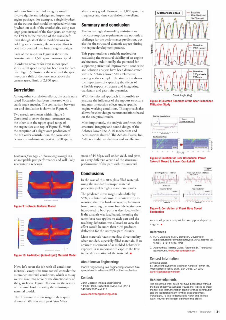
Volume 1 - Winter 2011 | 31
Continued from page 21 (Innova Engineering) >>> unacceptable part performance and will likely necessitate a redesign.
Now, let’s rerun the job with all conditions identical, except this time we will consider the as molded material conditions, which is to say we will take into account the directionality of the glass fibers. Figure 10 shows us the results of the same loadcase using the anisotropic material model.
The difference in stress magnitude is quite dramatic. We now see a peak Von Mises
stress of 45 Mpa, well under yield, and gives us a very different version of the structural performance of the part with this material.
ConclusionsIn the case of this 30% glass filled material, using the standard isotropic material properties yields highly inaccurate results.
The predicted stress magnitudes differ by 55%, a substantial error. It is noteworthy to mention that this loadcase was displacement based, meaning the same fixed deflection was introduced to both parts as described earlier. If the analysis was load based, meaning the same force was applied to each part and the resulting deflection was allowed to vary, the effect would be more than 50% predicted deflection for the isotropic part instance.
Most materials have some flow directionality when molded, especially filled materials. If an accurate assessment of as molded behavior is expected, it is important to capture the flow induced orientation of the material.
About Innova Engineering:InnovaEngineeringisaengineeringservicesfirmspecializesinadvancedFEAofthermoplastics.
Contact:JohnCogger,InnovaEngineering1ParkPlaza,Suite980,Irvine,CA92614949.975.9965ext.113
www.innovaengineering.com
Solutions from the third category would involve significant redesign and impact on engine package. For example, a single flywheel on the output shaft could be replaced with one flywheel on each of the crankshafts, using two large gears instead of the four gears, or moving the TVDs to the rear end of the crankshaft. Even though all of these modifications are holding some promise, the redesign effort is best incorporated into future engine designs.
Each of the graphs in Figure 4 show time domain data at 1,500 rpm resonance speed.
In order to account for even minor speed shifts, a full speed sweep has been run for each case. Figure 5 illustrates the results of the speed sweep as a shift of the resonance above the current speed limit of 2,800 rpm.
CorrelationAmong other correlation efforts, the crank nose speed fluctuation has been measured with a crank angle encoder. The comparison between test and simulation is shown in Figure 6.
Two speeds are shown within Figure 6. One speed is below the gear resonance and the other is in the upper speed range of the engine (see also top of Figure 5). With the exception of a slight over-prediction of the 4th order contribution, the correlation between simulation and test at 1,200 rpm is
already very good. However, at 2,800 rpm, the frequency and time correlation is excellent.
Summary and conclusionThe increasingly demanding emissions and fuel consumption requirements are not only a challenge for the performance prediction, but also for the structural dynamic aspects during the engine development process.
This paper outlines a suitable method for evaluating the structural viability of an engine architecture. Additionally, the potential for supporting structural improvement, root cause and solution analysis have been demonstrated with the Achates Power A40 architecture serving as the example. The simulation shows the importance of capturing the effects of a flexible support structure and integrating cranktrain and geartrain dynamics.
With the selected approach it is possible to evaluate the influence of the support structure and gear interaction effects under specific engine working conditions. This approach also allows for clear design recommendations based on the analytical results.
Most importantly, the analysis confirmed the structural integrity and sound design of the Achates Power, Inc. A-40 mechanism and permutations thereof. The Achates Power, Inc. A-40 is a viable mechanism and an effective
Figure 4: Selected Solutions of the Gear Resonance Mitigation Study
Figure 6: Correlation of Crank Nose Speed Fluctuation
Figure 5: Solution for Gear Resonance: Power Take-off Moved to Lower Crankshaft
means of power output for an opposed-piston engine.
References1. R.R.CraigandM.C.CBampton.Couplingof
substructuresfordynamicanalyses.AIAAJournalVol.6,No7,p1313-1319,1968
2. Adams/FlexTrainingGuide,AppendixD,TheoreticalBackground,www.mscsoftware.com
Contact InformationChristinaExner,Sr.StructuralDynamicsEngineer,AchatesPower,Inc.4060SorrentoValleyBlvd.,SanDiego,[email protected]
AcknowledgmentsThepresentedworkcouldnothavebeendonewithoutthehelpofmanyatAchatesPower,Inc.I’dliketothankthetestandinstrumentationteamsfortheircontributionandtheleadershipteamfortheirencouragement.Particularly,I’dliketothankKatieNorthandMichaelWahl,PhDforthediligenteditingofthisarticle.
Figure 9: Isotropic Material Model
Figure 10: As-Molded (Anisotropic) Material Model

UP IN THE AIR
ACROSS1. Eve is his other half
3. White blades cutting through the blue sky
5. Built ______ Tough
7. The future is...
8. To increase of decrease the engines power use the...
9. Get it in...
1 2 3 4
5
7
8
9
6
DOWN1. A part attached to or projecting from something
2. Not embassy but...
4. Sky - Boom
5. I’m not as strong as I used to be
6. Undercarriage
49
53
2
8
6
56
9
4
8
72
6
3
46
87
5
7
43
9
7
2
43
9
2
7
36
98
52
48
82
3
172
7
9
4
9
7
6
2
6
8
193
5
94
68
29
6
4
825463
1
5
49
5
594
718
1
29
5
9
276589
7
6
42
56
35
4
793
361
4
7
895
927
6
83
75
61
164
8
7
7
2
36
89
1
6
1
8
24
67
2
3
1
952
4
7
9
3
6
49
4
827
3
5
1
6
8
9
381
4
52
4
9
5
3
4


www.mscsoftware.com