MSc THESIS - CiteSeerX
141
Computer Engineering Mekelweg 4, 2628 CD Delft The Netherlands http://ce.et.tudelft.nl/ 2004 MSc THESIS Accelerating the XviD IDCT on DAMP Guido de Goede Abstract Faculty of Electrical Engineering, Mathematics and Computer Science CE-MS-2004-11 Future increases in processor clock speed only will not contribute to performance gains as in the past. Reconfigurable hardware is be- lieved to offer alternative ways of speeding up applications. This thesis project is part of the SMOKE project. SMOKE focusses on the acceleration of MPEG-4 operational kernels using reconfigurable hardware and is part of the MOLEN research theme. The major goal is to prove the usability of reconfigurable hardware to speed up mul- timedia applications. An MPEG-4 codec (XviD) is selected among four alternatives after a careful selection process. The codec is im- plemented on the DAMP platform. In order to create the software environment for this implementation, the Linux operating system is ported to the DAMP platform. The XviD codec is analysed and the computationally intensive parts are determined. The codec ac- celeration is achieved by migrating these kernels to reconfigurable hardware. Experimental results show that the IDCT kernel of XviD is accelerated by a factor of 1.86. When the colourspace conversion is moved to reconfigurable hardware, a speedup of 3.59 is achieved. By migrating both, the IDCT and the colourspace conversion to hard- ware a speedup of 1.40 is accomplished for XviD. The experimental results among with the DAMP platform analysis indicate that larger performance improvements for future DAMP versions can be expected.
-
Upload
khangminh22 -
Category
Documents
-
view
1 -
download
0
Transcript of MSc THESIS - CiteSeerX

Computer EngineeringMekelweg 4,
2628 CD DelftThe Netherlands
http://ce.et.tudelft.nl/
2004
MSc THESIS
Accelerating the XviD IDCT on DAMP
Guido de Goede
Abstract
Faculty of Electrical Engineering, Mathematics and Computer Science
CE-MS-2004-11
Future increases in processor clock speed only will not contribute toperformance gains as in the past. Reconfigurable hardware is be-lieved to offer alternative ways of speeding up applications. Thisthesis project is part of the SMOKE project. SMOKE focusses onthe acceleration of MPEG-4 operational kernels using reconfigurablehardware and is part of the MOLEN research theme. The major goalis to prove the usability of reconfigurable hardware to speed up mul-timedia applications. An MPEG-4 codec (XviD) is selected amongfour alternatives after a careful selection process. The codec is im-plemented on the DAMP platform. In order to create the softwareenvironment for this implementation, the Linux operating system isported to the DAMP platform. The XviD codec is analysed andthe computationally intensive parts are determined. The codec ac-celeration is achieved by migrating these kernels to reconfigurablehardware. Experimental results show that the IDCT kernel of XviDis accelerated by a factor of 1.86. When the colourspace conversion ismoved to reconfigurable hardware, a speedup of 3.59 is achieved. Bymigrating both, the IDCT and the colourspace conversion to hard-ware a speedup of 1.40 is accomplished for XviD. The experimental
results among with the DAMP platform analysis indicate that larger performance improvements for futureDAMP versions can be expected.


Accelerating the XviD IDCT on DAMPAccelerating the IDCT in XviD by migrating computation
intensive parts to hardware in the Altera Excalibur EPXA1
device on the DAMP platform.
THESIS
submitted in partial fulfillment of therequirements for the degree of
MASTER OF SCIENCE
in
COMPUTER ENGINEERING
by
Guido de Goedeborn in Rotterdam, The Netherlands
Computer EngineeringDepartment of Electrical EngineeringFaculty of Electrical Engineering, Mathematics and Computer ScienceDelft University of Technology


Accelerating the XviD IDCT on DAMP
by Guido de Goede
Abstract
Future increases in processor clock speed only will not contribute to performance gains asin the past. Reconfigurable hardware is believed to offer alternative ways of speeding upapplications. This thesis project is part of the SMOKE project. SMOKE focusses on the
acceleration of MPEG-4 operational kernels using reconfigurable hardware and is part of theMOLEN research theme. The major goal is to prove the usability of reconfigurable hardware tospeed up multimedia applications. An MPEG-4 codec (XviD) is selected among four alternativesafter a careful selection process. The codec is implemented on the DAMP platform. In order tocreate the software environment for this implementation, the Linux operating system is portedto the DAMP platform. The XviD codec is analysed and the computationally intensive partsare determined. The codec acceleration is achieved by migrating these kernels to reconfigurablehardware. Experimental results show that the IDCT kernel of XviD is accelerated by a factorof 1.86. When the colourspace conversion is moved to reconfigurable hardware, a speedup of3.59 is achieved. By migrating both, the IDCT and the colourspace conversion to hardwarea speedup of 1.40 is accomplished for XviD. The experimental results among with the DAMPplatform analysis indicate that larger performance improvements for future DAMP versions canbe expected.
Laboratory : Computer EngineeringCodenumber : CE-MS-2004-11
Committee Members :
Advisor: G.N.Gaydadjiev, CE, TU Delft
Chairperson: Stamatis Vassiliadis, CE, TU Delft
Member: F.L. Muller, CE, TU Delft
Member: N.V. Budko, EM, TU Delft
i

ii

I dedicate this document to my family for their love and support.
”If you look for truth, you may find comfort in the end; if you lookfor comfort you will not get either comfort or truth only soft soap
and wishful thinking to begin, and in the end, despair.” – C.S. Lewis
iii

iv

Contents
List of Figures vii
List of Tables ix
Acknowledgements xi
1 Introduction 11.1 Motivation . . . . . . . . . . . . . . . . . . . . . . . . . . . . . . . . . . . 11.2 Project description . . . . . . . . . . . . . . . . . . . . . . . . . . . . . . . 21.3 Project goals and main contributions . . . . . . . . . . . . . . . . . . . . . 21.4 Thesis framework . . . . . . . . . . . . . . . . . . . . . . . . . . . . . . . . 3
2 The DAMP platform and Linux environment 52.1 Platform specifications and limitations . . . . . . . . . . . . . . . . . . . . 52.2 Why Linux? . . . . . . . . . . . . . . . . . . . . . . . . . . . . . . . . . . . 72.3 Linux environment initialisation . . . . . . . . . . . . . . . . . . . . . . . . 82.4 Booting the kernel . . . . . . . . . . . . . . . . . . . . . . . . . . . . . . . 9
3 History of digital video 113.1 Introduction to still image compression . . . . . . . . . . . . . . . . . . . . 113.2 Lossy compression (JPEG) . . . . . . . . . . . . . . . . . . . . . . . . . . 123.3 Compressing image sequences (MPEG-1) . . . . . . . . . . . . . . . . . . 133.4 Improvements to MPEG (MPEG-2) . . . . . . . . . . . . . . . . . . . . . 153.5 The ISO MPEG-4 standard . . . . . . . . . . . . . . . . . . . . . . . . . . 15
4 Codec selection: Why XviD? 194.1 Available codecs . . . . . . . . . . . . . . . . . . . . . . . . . . . . . . . . 194.2 Codec motivation . . . . . . . . . . . . . . . . . . . . . . . . . . . . . . . . 204.3 Installation of the XviD codec on the PC . . . . . . . . . . . . . . . . . . 214.4 XviD library interface . . . . . . . . . . . . . . . . . . . . . . . . . . . . . 21
5 The XviD decoder evaluation 235.1 Exploring the XviD source code . . . . . . . . . . . . . . . . . . . . . . . . 235.2 Profiling the XviD codec . . . . . . . . . . . . . . . . . . . . . . . . . . . . 23
5.2.1 Profiling the codec on the PC . . . . . . . . . . . . . . . . . . . . . 245.2.2 Cross-compilation for the DAMP platform . . . . . . . . . . . . . . 24
5.3 Speeding up the codec . . . . . . . . . . . . . . . . . . . . . . . . . . . . . 25
v

6 IDCT hardware design 276.1 Inverse Discrete Cosine Transform . . . . . . . . . . . . . . . . . . . . . . 276.2 Hardware software separation . . . . . . . . . . . . . . . . . . . . . . . . . 286.3 Hardware implementation . . . . . . . . . . . . . . . . . . . . . . . . . . . 30
6.3.1 Hardware and software communication . . . . . . . . . . . . . . . . 306.3.2 IDCT hardware implementation . . . . . . . . . . . . . . . . . . . 326.3.3 Fitting the design into the FPGA . . . . . . . . . . . . . . . . . . . 35
6.4 Hardware performance . . . . . . . . . . . . . . . . . . . . . . . . . . . . . 366.5 XviD modification . . . . . . . . . . . . . . . . . . . . . . . . . . . . . . . 37
7 Experimental results 397.1 Methods of measuring . . . . . . . . . . . . . . . . . . . . . . . . . . . . . 397.2 Acquired results . . . . . . . . . . . . . . . . . . . . . . . . . . . . . . . . 40
7.2.1 Measurements . . . . . . . . . . . . . . . . . . . . . . . . . . . . . 407.2.2 Speedup calculation . . . . . . . . . . . . . . . . . . . . . . . . . . 407.2.3 IDCT operation time . . . . . . . . . . . . . . . . . . . . . . . . . . 417.2.4 Improving hardware IDCT speed . . . . . . . . . . . . . . . . . . . 43
8 Conclusions and recommendations 458.1 Summary . . . . . . . . . . . . . . . . . . . . . . . . . . . . . . . . . . . . 458.2 Main contributions . . . . . . . . . . . . . . . . . . . . . . . . . . . . . . . 458.3 Recommendations for future research . . . . . . . . . . . . . . . . . . . . . 46
Bibliography 48
A IDCT source code 49
B Source code of test program: xvid decraw.c 55
C Profiling results on the x86 platform 77
D IDCT datapath and controlling FSM 89
E Source code of XviD decoder: decoder.c 95
F GNU General Public License 117
vi

List of Figures
2.1 Features designed for the DAMP platform, source page 12 of [28]. . . . . . 6
3.1 Subsequent images, each containing similar parts. . . . . . . . . . . . . . . 143.2 Dependencies between I, P and B frames. . . . . . . . . . . . . . . . . . . 143.3 Example of a scene containing grouped media objects, source [18]. . . . . 16
6.1 Thinnest links in terms of communication between functions. . . . . . . . 296.2 Datapath of the implemented IDCT with row/col unit. . . . . . . . . . . . 336.3 States of the FSM controlling the IDCT datapath. . . . . . . . . . . . . . 346.4 Simulation of several signals from the FSM controlling the IDCT datapath. 36
7.1 Average decoding time per frame for four reference MPEG-4 files mea-sured for six different configurations of IDCT and colourspace conversion(CSPC). . . . . . . . . . . . . . . . . . . . . . . . . . . . . . . . . . . . . . 41
7.2 Average relative speedups for six different configurations of IDCT andcolourspace conversion (CSPC). . . . . . . . . . . . . . . . . . . . . . . . . 42
D.1 Quartus design of the row/col unit. . . . . . . . . . . . . . . . . . . . . . . 90D.2 Quartus design of ”IDCT DEEL” block which is part of the row/col unit. 91D.3 Quartus design of the IDCT datapath. . . . . . . . . . . . . . . . . . . . . 92D.4 Simulation of all the signals originating from the FSM controlling the
IDCT datapath. . . . . . . . . . . . . . . . . . . . . . . . . . . . . . . . . 93
vii

viii

List of Tables
4.1 Codec comparison . . . . . . . . . . . . . . . . . . . . . . . . . . . . . . . 20
5.1 Average decoding time of MPEG-4 files while selectively disabling theIDCT or the colourspace conversion and maximum obtainable speedup . . 25
6.1 Cell usage of the EPXA1 device for the row-only, column-only and row/colunit . . . . . . . . . . . . . . . . . . . . . . . . . . . . . . . . . . . . . . . 32
7.1 Average decoding time of MPEG-4 files while selectively disabling theIDCT or the colourspace conversion and maximum obtainable speedup . . 40
7.2 Average decoding time per frame . . . . . . . . . . . . . . . . . . . . . . . 417.3 Average IDCT operation time per frame. . . . . . . . . . . . . . . . . . . 427.4 Total average time per IDCT for software and hardware and calculated
speedup of the kernel for each file. . . . . . . . . . . . . . . . . . . . . . . 437.5 Average IDCT operation time per frame and predicted future values. . . . 44
ix

x

Acknowledgements
During the different stages of my M.Sc. project, several people have helped to reflectabout the direction the project was headed and to focus on the important topics. Duringmy thesis project, which is part of the SMOKE project, I have spent a lot of timetogether with Jonathan Hofman, whom I was cooperating with on the SMOKE project.We helped to keep each other focussed during the months we spent together. Especiallyin the summer when many people went away to enjoy their vacation and the weatherwas nice, the fact that I had someone to share with made the project a lot more fun. Iwant to thank Jonathan for sticking with me when I wanted to finish in time, even whenthat meant giving up his vacation.
Apart from my partner in crime, I also wish to thank my advisor Georgi Gaydadjievwho spent so much time reading the documents we produced and who helped us duringthe project every time we had questions or needed something. He also arranged forsomeone to assist us on the SMOKE project when implementing the network interfaceand porting Linux. Thanks for helping us to have our defence in November! I also wantto thank Juan Fernandez for working with us on the network interface.
I want to thank Stamatis Vassiliadis, for allowing us to start the SMOKE project. Iwant to thank Bert Meijs for supplying and helping us installing the computers to workon and for allowing us to print our theses. I want to thank my parents and family forsupporting me in my education, both financially and emotionally. I owe a great deal totheir kindness and patience! I believe in God and I want to thank Him as well for givingme the opportunity to study at this University in a free country and for the offer Jesusmade to bring forgiveness for my mistakes, since I am not perfect while He is.
Guido de GoedeDelft, The NetherlandsDecember 7, 2004
xi

xii

Introduction 1This M.Sc. project entails the speeding up of the XviD codec by implementing the IDCTin hardware. It is part of a larger project called SMOKE1 [14] which aims to speed upXviD. For information on different implemented modifications to XviD the reader isreferred to [13].
In section 1.1 the performed research is motivated. The project is described in section1.2. Section 1.3 will elaborate on the goals of the project and the expectations for theusability of reconfigurable hardware. The thesis framework is described in section 1.4.
1.1 Motivation
The concept of using reconfigurable hardware to enhance the functionality of computersystems has gained much attention recently [20]. There are many projects on this topic,one of which is MOLEN [23]. The MOLEN project was started at the faculty of ElectricalEngineering of the TU Delft, focussing on creating a paradigm to integrate the use of re-configurable hardware into software. The SMOKE project is part of the MOLEN project.SMOKE focusses on the acceleration of operational kernels in MPEG-4 using reconfig-urable hardware. There is a huge demand for computer systems capable of performingmultimedia applications. For video and 3-d rendering applications faster processors areneeded. Intel recently announced [19] that they will not be making processors runningat 4 GHz in the near future. Instead of speeding up the processor by increasing clockspeed, their approach is to utilise more than one processor core on a chip.
It evidently becomes more difficult to speed up sequential processors. Reconfigurablehardware in short range of the CPU can offer a solution. In multimedia applications,many small operations have to be performed on large quantities of data. These opera-tions are now performed by a central processor, but they could be performed in parallelby hardware designed especially for that operation. It is envisioned that addition ofreconfigurable hardware to general purpose processors can provide the means for suchparallelism.
Besides the technical limitations to increase the clock speed of processors, anotherissue is important especially for mobile devices delivering multimedia applications. In-creasing the clock speed increases the demands on power usage. Mobile devices havelimited power budget, so clock speed cannot be increased to the speed needed for theapplication2. This project intends to demonstrate the usability of reconfigurable hard-ware for multimedia applications running on relatively slow platforms.
1SMOKE is an abbreviation of Speeding up MPEG-4 Operational Kernels on Excalibur [14]2Contrary to personal computers containing 3 GHz processors, mobile devices generally contain
processors running at speeds less than 200 MHz. For example the Sony Ericsson P800 and P900 devicescontain ARM processors running at 156 MHz [4].
1

2 CHAPTER 1. INTRODUCTION
One type of multimedia application that is performed often in devices nowadays isvideo decoding. Mobile devices have limited storage space and connection speeds, sovideo needs to be highly compressed. The type of video encoding used in mobile devicestoday is MPEG-4. It will be proven that using reconfigurable hardware on such plat-forms can significantly improve performance for multimedia operations. To this extendan MPEG-4 decoder will be implemented and sped up using reconfigurable hardware.Section 1.2 will describe the project in more detail.
1.2 Project description
The aim of the project is to modify an existing MPEG-4 video decoder to use thereconfigurable hardware available on a specific hardware/software platform, the DAMPplatform. It contains re-configurable hardware which will partly take over the decodersfunctionality in order to speed up the decoding process. The platform will be describedin chapter 2.
The used approach is to explore which parts of the decoder will benefit the mostfrom the migration to hardware and to design special hardware for those parts, whileregarding the way the software and the hardware communicate. The project trajectorycan be summarised as follows. First, the codecs will have to be evaluated in order todetermine the most suitable one for this project. After that, one codec will be chosento run on the DAMP board. The DAMP board will be running Linux as its operatingsystem to support the codec. Finally, when the codec is working on the DAMP board itwill be modified to make use of the available re-configurable hardware. The goals of theproject will be described in section 1.3.
1.3 Project goals and main contributions
The research consists of determining the suitability of the reconfigurable hardware onthe DAMP platform for multimedia applications. It is intended to determine this bymodifying an MPEG-4 decoder in such a way that it uses the DAMP reconfigurablehardware to speed up its operation. The aim is to create a working MPEG-4 decoderin an operating environment that allows for adequate measurements and comparison.Speedup measurements will give valuable information about the possibilities for such adesign in MPEG-4 products.
As seen in other projects concerning the combination of software and reconfigurablehardware [8], one needs to keep in mind the overhead produced by the necessary com-munication between hardware and software. The total amount of time involved in thecommunication and computation should be less than the original software-only approach.It is expected that reconfigurable hardware can be used in many applications, making itan advantage for processors to have reconfigurable hardware available to them [25, 6].
This project intends to prove the suitability of the use of reconfigurable hardwareon the DAMP platform to speed up multimedia applications. The DAMP platform isbuilt around an Excalibur device. It contains an ARM processor which is used in manyother implementations where MPEG-4 video is used, such as in numerous mobile devices

1.4. THESIS FRAMEWORK 3
[1]. It is conceived that the use of such reconfigurable hardware can bring the currentlyavailable devices using MPEG-4 to a higher level of performance and versatility.
The main contributions of this project are stated below.
• Addition of a network controller to the DAMP board.
• Porting Linux to the DAMP platform.
• Researching the currently most suitable codec to be used and modified for researchprojects.
• Determining the computation intensive parts of the XviD codec.
• Delivering a fully functional IDCT core in reconfigurable hardware.
• Speeding up the XviD codec on the DAMP platform using the available reconfig-urable hardware.
• Creation of a test program to decode MPEG-4 reference files using the createdIDCT and colourspace conversion cores.
• Creation of a test program to output decoded images to the VGA controller andto measure the time needed for the decoding and displaying of each frame.
1.4 Thesis framework
This document is organised as follows. Chapter 2 will describe the environment that isused to operate in. It will describe the platform, the software environment and its config-uration. In chapter 3, an overview of the history of digital video is provided, introducingstill image compression and various moving images compression techniques. Section 3.5will describe the ISO MPEG-4 standard. Chapter 4 will discuss the decoder selectedfor this project after which it is explored further in chapter 5. To speed up the selecteddecoder, dedicated hardware is designed and evaluated in chapter 6. Experimental re-sults about the obtained speedup by the modifications performed to the decoder, can befound in chapter 7. Chapter 8 concludes the document and gives recommendations forfuture research.

4 CHAPTER 1. INTRODUCTION

The DAMP platform andLinux environment 2The DAMP platform will be the target platform of the MPEG-4 codec used in thisproject. On this platform, the speeding up of the decoding part of the codec will takeplace. The DAMP platform was designed as an M.Sc. project at the TU-Delft in 2003,about which additional information can be found in [28] and [9]. It contains an AlteraExcalibur device which combines an ARM processor stripe with reconfigurable FPGAfabric and various peripheral devices on a single chip. Section 2.1 will describe theDAMP platform in more detail. The chosen software environment is Linux combinedwith an ARM boot-loader. The choice of Linux will be explained in section 2.2. Section2.3 describes the initialisation of the software environment. Finally, section 2.4 describesthe booting of the Linux kernel. More information about the software environment canbe found in [13].
2.1 Platform specifications and limitations
The DAMP platform is built around the Altera Excalibur device EPXA1F672C3 as de-tailed in [6]. It was designed to be a platform for the creation and testing of embeddedsystems targeting multimedia and mobile devices. The Excalibur contains an ARM922Tprocessor with peripherals and an Altera FPGA with 4160 logical elements (cells). Nowa-days the ARM processor can be found in many portable devices. This makes DAMP aversatile development platform for such devices. Hardware and software co-designs canbe created on it using the Quartus II development software [7]. The DAMP platformcontains the following parts which are of importance to the targeted design.
• the Excalibur device, containing an ARM processor and a programmable logicdevice (PLD).
• a FLASH memory to store the bootloader software.
• a JTAG interface for configuring the hardware and programming the bootloaderinto FLASH.
• an SDRAM to store the multimedia data.
• a UART interface to communicate externally with the operating system.
• a VGA output which can be controlled from the PLD to output decoded images.
• a network interface for access to large files1.1The network interface was designed to be on the DAMP platform, but on the prototype it was not
available yet, due to footprint errors. However for the continuation of the project, the implementation
5
6 CHAPTER 2. THE DAMP PLATFORM AND LINUX ENVIRONMENT
12 CHAPTER 2. DAMP SPECIFICATION
Excalibur
Altera
Clock Circuit
in outAudio (stereo)
SDRAM
IDE Interface
InterfacePS/2 PS/2
PS/2 signals (2)
I/O Pins
I/O Pins
I/O
Pin
s
I/O
Pin
s
232232
USB Controller User I/O
UARTEthernet Controller
JTAG Interface
Optional FPGA
Interface
VGA LCD
Video Out Flash Memory
RJ45
USB
Daughter Card
Adress
Clock
JTAG JTAG
Signals to LED’s
Data
NIOS
NIOSNIOS
Extension
UART lines (16)
Ethernet signals
Daughter card
interface lines (85)
USB signals
JTAG lines (10)
VGAlines
Audio lines
(+ extension lines)
npor
nconfig
Clock lines (5)
initdone
OSC
ATX
Power Circuit
Signals from PS/2Signals from buttons
Reset Circuit
Adress
Clock
Data
IDE
Lines
FPGA
lines
Figure 2.1: Proposed Features, Requirements and Signal-flow for DAMP board.
an external 5V or 9V power supply (not ATX) and several voltage regulators on thedevelopment board. This increases the complexity of the PCB design, however anexternal ATX power supply is not required.
Based on the previous discussion, the decision was made to implement the fol-lowing. The Power Circuit should use an ATX power supply, which delivers most of therequired voltages to the DAMP board. Since the ATX power supply doesn’t provide
Figure 2.1: Features designed for the DAMP platform, source page 12 of [28].
More details on the above and other DAMP features can be found in [9] and [28].Performing the project on the DAMP platform showed that this version of the
design, which is actually the first prototype, has certain limitations. The speed of theSDRAM cannot be set to the desired maximum of 83 MHz2 supported by this Excaliburdevice. Instead, it has to be set to the lowest possible speed of 12.5 MHz to maintain
of a network device was necessary. An external network device has been literally soldered to the DAMPboard.
2The current EPXA1 speedgrade 3 Excalibur device supports SDRAM at 83 MHz, but the speedgrade1 device would support SDRAM up to 133 MHz.

2.2. WHY LINUX? 7
system integrity. Higher speeds cause the system to become unstable and to crash withina short amount of time. It is expected that mentioned crashes are due to misalignmentbetween lengths of data, address and control lines of the SDRAM connections on theDAMP PCB. However, transient simulation of the PCB would be required to verify thishypothesis. Future versions of the DAMP platform are expected to have overcome thisproblem, but for this project only the limited prototype is available.
The used prototype has footprint errors, giving rise to the need of connecting sev-eral chips off-board via wires, which would otherwise have been mounted on the PCB.For instance the FLASH memory was connected to the PCB using this method. Thewires make the device more sensitive to environmental noise and mechanical movements.Because of this, only one 4 MB FLASH device was connected to the PCB. This smallFLASH memory is inadequate for providing a filesystem to the operating system. Useof the network interface became evident. The network option that was designed to beon the board had not been implemented due to the incorrect footprint of the networkcontroller. Implementing the network interface had to be done by connecting wires fromthe PCB to a separate network controller. This way the operating system was enabled toaccess large non-volatile storage media, instead of the limited FLASH memory. Detailson the connection of the network device and modification of the ethernet driver in Linuxcan be found in [13].
The VGA interface has a simple DA-converter, consisting of a resistor network foreach colour channel, to enable the use of 256 colours on an external display. In the fu-ture higher resolution DACs could provide the board with more colours. However for thedemonstration of the decoding process 256 colours will suffice. The hardware to supplyvalues to the DA converters of the VGA interface has to be built inside the PLD. Thiswill leave only part of the PLD for the design of auxiliary hardware to speed up softwareon the platform. The used Excalibur EPXA1 device is rather small since it has only4,160 logic elements (cells). From the same device family the EPXA4 exists. It has thesame footprint as the EPXA1. The EPXA4 has 16,640 logic elements. Another deviceof the same family, the EPXA10, has more logic elements, but it does not have the samefootprint as the EPXA1 and EPXA4. In the future the larger EPXA4 device could bemounted on the PCB, giving additional design freedom.
Figure 2.1 shows all the features for which the DAMP platform was designed. Notall of these features are available on the prototype. For details on which features areimplemented by the designers of the prototype, the reader is referred to page 12 of [28],where figure 2.1 is explained in detail.
2.2 Why Linux?
When implementing an MPEG-4 codec for the DAMP platform, one will need to be ableto validate the correct functionality of the codec. Therefore, the ability to open files andto write back the results (or possibly display the results) is required. Regardless of theway in which an MPEG-4 codec will be implemented, to properly test and compare thecodecs functionality, the use of an operating system can hardly be avoided.
Linux is an operating system that can be used freely and has already been portedto comparable Excalibur boards. One could argue that implementing the codec without

8 CHAPTER 2. THE DAMP PLATFORM AND LINUX ENVIRONMENT
the use of an operating system would also be possible. However, in the early stages ofthis project it would save time to port Linux to the DAMP platform for several reasons.One being that the porting of Linux is better documented but would require more orless the same effort as would porting the codec without an operating system. Secondly,since Linux has already been ported to comparable ARM boards, most of the effort ofporting Linux has already been made. Using Linux allows postponing the final decisionabout the codec to a later stage of the project. In addition, porting Linux would givemore insight in the DAMP board. This would allow for better motivating the choice ofthe codec. Considering the above, for this project Linux was preferred to run the codecon, instead of creating a standalone application.
2.3 Linux environment initialisation
When Linux is compiled from source code, an image file is created containing the neces-sary instructions for the processor to boot Linux. This image however can only be usedwhen different parts of the platform have been properly initialised. To obtain properinitialisation, a bootloader has to be used, which is the software that initialises the hard-ware before the operating-system starts. The bootloader used for the DAMP board isthe open source project ARM-boot.
ARM-boot initialises the memory (SDRAM) and starts a terminal which is accessiblevia the serial port. It can be set-up in such a way to automatically load a kernel imagefrom the FLASH memory to the SDRAM when booting, but it also supports loadingblocks of data into memory from the serial port. However the serial port is slow, so it isnot suitable for uploading large amounts of data. To this extend the much faster networkinterface should be used. The TFTP boot protocol can be used to load an image intomemory and boot from it. These images will then be used to boot the kernel as will beexplained in section 2.4.
When an image containing the kernel of Linux is loaded into the FLASH memory,ARM-boot can be instructed to boot that kernel from FLASH. The FLASH memory is 4MB (megabytes) large, of which less than 1 MB is used for ARM-boot. The Linux-kernelalso takes less than 1 MB. This leaves over 2 MB of the FLASH memory for the filesrequired after booting. These files are put together into a compressed image file, calledthe filesystem image. In the filesystem the cross-compiled codec and video-files to workon, also have to be present. Having the filesystem in the FLASH memory however is notpractical, since the FLASH size is small and FLASH devices have a limited number ofwriting cycles. To provide support for a larger filesystem the network interface is needed.
For testing the correct operation of the network interface the built-in functionalityin ARM-boot to use TFTP was used. Using the TFTP boot protocol ARM-boot canload a configuration file from a server, containing the image of the kernel and the filesystem. This removes the limitation of the size of the FLASH interface and the speed ofthe serial interface for uploading files to the system.
The FLASH memory is large enough to contain the kernel image without the filesys-tem. The kernel can then use the network interface to connect to an external filesystem.Having the kernel boot from FLASH gives two advantages. The FLASH is still used toboot, so no TFTP server is needed. Secondly, data does not have to be written to it,

2.4. BOOTING THE KERNEL 9
because the filesystem resides elsewhere. The addition of the network interface and themodification of the bootloader are described in [13].
2.4 Booting the kernel
Normally when ARM-boot starts, the kernel-image from the FLASH is decompressedinto SDRAM and executed. However, care must be taken when installing the kernel.The used Linux kernel contains settings that depend on the configured processor speed.It has been used on boards similar to DAMP, such as the EPXA1 development board.Since the processor speed on the DAMP board differs from the speed the Linux kernelwas configured for, these settings are incorrect and have to be changed.
When Linux was ported to the DAMP platform a hardware configuration file hasbeen used for configuring the hardware on the DAMP platform. It had originally beengenerated by the Quartus design tools from Altera. Because the file has been auto-matically generated it contains directives to the reader not to change this file, since allchanges would be lost the next time the file is generated. However, the configuration fileis distributed with the used Linux kernel (version 2.4.19-rmk7) separately from Quartus,therefore it would not be updated. In fact it has to be changed manually when one isporting Linux to the DAMP board, since the settings of this board are slightly differentfrom the one the kernel was created for. The latter was the main reason for the problemswe encountered in the early stages of the project. The settings of the clock frequency ofthe DAMP board in the mentioned file were wrong. The incorrect setting resulted intogarbage characters on the screen coming from the DAMP board serial port. The speedat which the serial port communicates with the computer is directly dependent on theclock speed set in the file. A wrong clock speed results in a non-standard serial portbaudrate, causing these garbage characters. To obtain the correct settings for the DAMPboard, without again using Quartus to generate such a file, a similar file from ARM-boothas been used, which had also originally been obtained from a project compiled withQuartus. It obviously contained the correct settings, since ARM-boot already workedfine using the serial port. This made it possible to verify that Linux was indeed bootingup until a certain point.
At first when trying to use the filesystem with an image in FLASH memory, Linuxwas unable to use the filesystem contained in the image file. It contained improper devicenodes, which are files giving access to hardware devices using system calls. After creatingthe proper device nodes in the filesystem image and changing the clock settings Linuxdid boot up completely. Compiled programs could now be run on the DAMP board fromwithin Linux, but there still was too little space for data files. Also large programs withlibraries like the XviD codec did not fit. To solve this, the network connection proved themost beneficial addition. It speeds up the communication and makes the use of largerfiles feasible. With the working network interface, the system can function properly. Itenables the use of large files to test the functionality of the codec as will be done inchapters 4 and 5. The modifications made to the device nodes and to the clock speedsettings of the kernel, are explained in [13].

10 CHAPTER 2. THE DAMP PLATFORM AND LINUX ENVIRONMENT

History of digital video 3In the past decades different standards for recording analogue video have been intro-duced [21]. These video standards offer colour image information at roughly 13,5 millionimage pixels per second. Digitising such a video stream would require one to process216 Mbits per second, according to the CCIR 601 standard [24]. Nowadays computersare fast enough to process data at rates of this magnitude, however storing the video ondigital media would require prohibitively large storage space.
Throughout history efforts have been made to reduce the size of video streams, with-out losing visual quality [2]. These efforts began with the need to compress digital stillimages for storage as introduced in section 3.1. Section 3.2 will explain the basics oflossy still image compression. After this, section 3.3 expands the focus from still imagesto sequences of images and their compression using MPEG. Section 3.4 discusses im-provements made to the initial lossy video encoding techniques. Section 3.5 elaborateson the ISO standard for MPEG-4 [18] as created by the International Organisation forStandardisation1.
3.1 Introduction to still image compression
An image basically consists of a 2-dimensional plane of dots called pixels, each pixelcontaining colour information. A standard computer screen is at least 640 pixels wideand 480 pixels in height. This equals 307200 pixels. Each pixel consists of 3 values, onefor red, one for blue and one for green colours. Mixing these three basic colours createsthe impression to the human eye of a certain colour being present [3]. One can see that,when each pixel would have 24 bits for colour information (one byte for each colour),the number of bytes needed for one full screen image is over 9 · 105 bytes. In the earlydays of computer imaging this was an enormous amount of data. Even for images withonly 256 colours (one byte per pixel), still 3 · 105 bytes were needed. Evidently, imagesneeded to be compressed.
The first type of compression that naturally comes in mind, is using readily availabledata compression algorithms to compress these images. Many images contain largeplanes of the same colour. For images with only a small amount of colours comparedto the number of pixels in the image, reasonably good compression can be obtained.This compression is called lossless compression, since it is done without any data losses.One such lossless compression technique is the Graphics Interchange Format [15]. Thelossless compression of image sequences also became possible in this way, concatenatinga sequence of compressed images, for instance in a format called FLIC [17].
1The abbreviation ISO comes from the Greek word ”ισoς” meaning equal. The use of this word ISOis chosen because the International Organisation for Standardisation would be abbreviated differently indifferent languages, for example IOS in English and OIN in French.
11

12 CHAPTER 3. HISTORY OF DIGITAL VIDEO
3.2 Lossy compression (JPEG)
When a person looks at a picture, not all parts of the picture have the same relevance.People remember pictures subjectively and are generally not capable of regeneratingevery detail of an image from memory. This gave rise to the idea to save only thoseparts of an image that people are most sensitive to, instead of keeping every pixel in animage and trying to compress the whole without loss of information.
When trying to store only relevant parts, one needs to determine when data is rel-evant. The first thing to look at to determine what image data is relevant for humans,is the human eye. The retina contains parts called cones sensitive to colour and partscalled rods sensitive to light intensity [12]. The centre of the eye contains more conesand the larger surrounding part of the eye contains more rods. This renders the eye ingeneral more sensitive to light intensity. There are three different types of colour sen-sitive parts, one type sensitive for red, one for green and the third for the colour blue.Digital pictures generally consist of a number of pixels, for which each pixel containsthree values, one for the intensity of each of the three colours present.
As explained in the previous paragraph, the human eye is most sensitive to changesin light intensity and less to changes in colour. Therefore it makes sense to store imagesin a format which exploits this property. A pixel then contains one value, called luma2
, for the light intensity and two values called chroma, representing the chrominance,determining the colour of the pixel. Since the changes in colour are less noticeable, thechroma values of 4 pixels together are averaged, leaving only two chroma values for agroup of 4 pixels, so instead of 2 values per pixel one now has 1/2 value per pixel. Thisreduces the amount of information per pixel by a factor of 2, since at first 3 values forthe red, green and blue components were needed for each pixel, but now 6 values per 4pixels are needed.
When applying this process to images, the subjective quality of the image does notchange much, however the process does leave out information and is irreversible. Suchan irreversible process is called lossy, since information is lost. Apart from colour infor-mation, properties of human perception leave room for more optimisations by leavingout unimportant information. Another example of what can be optimised, is the humanperception of changes in a picture. High frequency spatial differences between pixels areless noticeable than gradual changes, since the eye tends to blur the image. Thereforewhen looking at an image in the frequency domain, only the low frequencies are per-ceived and matter the most.
By performing a discrete cosine transform (DCT) on the image it is transformed intothe frequency domain and the values that matter the most can be prioritised. Tests haveshown for human perception, that after removing (or severely rounding) the higher fre-quency components from the image and then transforming back, the subjective qualityonly marginally changes. This opens opportunities for the idea of quantisation. Whenlimiting (quantising) the values after the DCT to a certain set of values, less informa-tion is needed to describe the remaining values after quantising. This process is lossy,
2The use of the word luma is preferred over the word luminance to note the difference between thenon-linearly transformed value used in digital images and the real luminance value from colour theory.This is explained in [22]

3.3. COMPRESSING IMAGE SEQUENCES (MPEG-1) 13
however the subjective quality loss can be adjusted to be acceptable for the amount ofstorage space that is saved in the process.
One standard using these techniques is the JPEG standard (Joint Photographic Ex-perts Group standard) incorporated into the JPEG File Interchange Format (JFIF) [11].Since its introduction, it has become the most used format for photographic pictures.Due to its small file sizes it is very suitable for transferring images via the internet. It isalso possible to create more versions of the same picture, in different qualities, to suitedifferent needs.
3.3 Compressing image sequences (MPEG-1)
The technique for compressing images by only keeping relevant data, can also be appliedto moving pictures. These are essentially subsequent snapshots, creating a sequence ofimages. The images can be compressed using for instance JPEG. Compressing eachframe individually is what a Motion-JPEG codec does.
Advantages of such a method are that it is just as operation intensive as JPEGcompression and it can be done out of order or in parallel on different frames of a videosequence. However the compression ratio reached leaves much to be desired, since videofiles still are very large using such a codec, because they consist of many images. Onecan distinguish a fundamental difference between video compression and single imagecompression. The subsequent images of which a video consists are generally very similarto each other. Somehow one should take advantage of this property, but the Motion-JPEG codec certainly does not, because it only emphasises on separate images.
The Moving Pictures Expert Group (MPEG) developed a standard [5] that does useproperties of the subsequent frames for achieving compression. Since many frames arealike, only the difference between one frame and the next is saved, reducing the amountof information needing to be stored. Every now and then a scene changes in such away that a frame is completely different from the previous one. In that case the frameis saved entirely, compressed in a way similar to JPEG. Those individually compressedframes in MPEG are called I-frames. The frames that only store the difference comparedto previous frames are called P-frames.
Suppose a picture contains a tree and a building in the background and a locomotivedriving by. At first one sees one side of the building, but later that part of the buildingis covered by the moving locomotive and the part of the tree that was first covered bythe locomotive is visible again. After the locomotive is gone, the image is very similarto the image that described the background before the arrival of the locomotive, so oneis likely to use a P-frame and store only the difference compared to the previous frame.
There is a third way of storing compressed frames. During the presence of thelocomotive, the scene changes in such a way that a frame could be stored with lessinformation if one would refer to a future frame instead of a past frame. This is whereB-frames are designed for. They can build up a current frame using information from aprevious P (or I) frame and a following P-frame. The described scene with the locomotiveis depicted in figure 3.1. In this figure, frame 1 could be an I frame or a P frame. Frame3 can be stored as a P frame containing information from the previous I frame. Frame2 contains information obtained from frame 1 and frame 3 so it can be stored as a B

14 CHAPTER 3. HISTORY OF DIGITAL VIDEO
Figure 3.1: Subsequent images, each containing similar parts.
Figure 3.2: Dependencies between I, P and B frames.
frame. B frames cannot refer to other B frames, because this would make the decoderstoo complex. Now only an I frame and one or two P frames are needed to reconstructa frame from a B frame. If B frames would refer to other B frames as well, all theseB frames would have to be stored while decoding. The dependencies between I, P andB frames are depicted in 3.2. Groups of P, I and B frames are placed together in apredefined order into a GOP (group of pictures). The MPEG-1 standard has certainlimitations, such as the maximum bitrate, as well as limitations to the size of a GOPand the number of each type of frames in it, providing an upper constraint on quality.The MPEG-1 format has been extended in various ways since its first definition, as willbe explained in section 3.4.

3.4. IMPROVEMENTS TO MPEG (MPEG-2) 15
3.4 Improvements to MPEG (MPEG-2)
A newer standard, called MPEG-2 has been developed to be more of a generic codingstandard, but still to be adaptable depending on the medium that will be carrying theMPEG-2 stream. The idea is to have enough standardisation to provide compatibilitybetween different applications, but yet to be flexible enough to permit a degree of free-dom when implementing the applications.
Apart from the features designed into MPEG-1, other options have been added toMPEG-2. It contains the possibility to use other sampling standards for storing the lumaand chroma information of the pictures. It also has the possibility to handle interlacedvideo, in which at doubled frame rate one frame contains only the even lines and thenext frame contains the odd lines of a picture. Depending on whether there is much orlittle motion, different ways of compressing this interlaced video are supported [2].
Another improvement in MPEG-2 is that it now allows the bitrate to be varied de-pending on the quality required. In MPEG-1 the bitrate was kept constant by performingadaptive quantisation and thus losing more information. In MPEG-2 this adaptive quan-tisation can now be used to assure quality.
Finally, scalability is added by allowing different resolutions to be encoded incre-mentally. First the low resolution image is encoded and the higher resolution image isencoded secondly, based on the differences with the lower resolution image.
Not every MPEG-2 encoder will support each option. However they will all producean MPEG-2 stream adhering to the standard. So all produced streams can be decoded.Thus one might choose to build a simple encoder, implementing only the possibility tocreate a stream of I-frames (with a complexity similar to Motion-JPEG) for example.Still this stream conforms to the standard and can be decoded. This is how specificvideo editing applications create MPEG-2 video, when the type of GOPs to use has notyet been specified. In that case all frames are stored as I-frames, to be converted to I, Band P frames later at a relatively small quality trade-off. MPEG-2 is the standard usedin DVDs, possibly containing up to almost 9 GB of information for a few hours of video.For use on the internet video files should be smaller. Currently the most used standardfor video distribution on the internet is MPEG-4. Section 3.5 will go into detail aboutthe MPEG-4 video standard which is used in this project.
3.5 The ISO MPEG-4 standard
The MPEG-4 standard is developed by the International Organisation for Standardisa-tion. It is the successor of MPEG-1 and MPEG-2 and has been designed to be a standardwith the advantages of its predecessors, but with enhanced functionality. Researchersand engineers from different countries have cooperated in designing the MPEG-4 stan-dard. Pieces of the standard were developed by separate teams.
Several meetings were held lasting for up to one week. In the time before these meet-ings, members have electronically sent in their contributions, allowing other membersto review them to speed up the process. During the meetings, plenary discussions wereheld, as well as subgroup discussions. Occasionally a group was formed to continue untilthe next meeting. Their deliverables were then presented and used in the next meeting.

16 CHAPTER 3. HISTORY OF DIGITAL VIDEO
Figure 3.3: Example of a scene containing grouped media objects, source [18].
At each meeting around a hundred documents are created, of which the ones describingthe standards under development are of particular importance. This section describesthe major parts of the MPEG-4 standard as detailed in [18].
The idea behind MPEG-4 is to offer a framework to hierarchically combine differentmedia objects, such as images, video, audio and text. These primitive media objects canbe grouped together forming a tree structure. In this tree a subtree, which representsthe grouped media objects, can again be identified as a compound media object. Forinstance, a video of a person talking, combined with the audio of this persons speech canbe grouped together into a compound media object. Groups of compound media objectscan form a 2-dimensional or 3-dimensional space. The media objects can be created byrecording of images, video or sound, but they could also be generated by a computer.So either natural or synthetic media objects can be used. Different media objects suchas audio, 3-d objects or sprites (still images) are multiplexed with control data into onestream. In figure 3.3, an example is given of how media objects can be grouped togetherto form compound media objects. In this figure the woman talking, the whiteboard

3.5. THE ISO MPEG-4 STANDARD 17
behind her, the desk and her voice as well, are separately created objects. The womancan be natural video and her voice could be recorded audio. The desk could be a 3-drendered synthetic object and the whiteboard could be a computer generated 2-d imageor an audiovisual presentation containing both images and audio. For the hypotheticalviewer these objects together would form a 2-d view in the video compositor projectionplane as indicated in the figure. Changing the viewpoint could be allowed by the authorto change the way the grouped objects would appear to the viewer.
The MPEG-4 standard provides the author of the content the possibility to producecomplex multimedia content, while making it easier to reuse content. For example thedesk in figure 3.3 could be used in other content as well. Also the author is given thepossibility to restrict the user of the content and to protect the owners rights. The usercan be given more freedom to experience the content that is created. For example in a 3-d environment, the user can view the content from different angles only if allowed by theauthor. Also MPEG-4 contains standards for many applications such as standards forlow bitrates. This yields the possibility to provide MPEG-4 content via low-bandwidthchannels like the ones used in mobile communications. Besides the larger freedom andthe greater amount of applications, the user is offered more interaction with the content.Depending on the actions of the user, different content could be provided to the user.One could imagine the user participating in the provided content, making it specificallytailored to the end user.
Apart from the author and the user, MPEG-4 also offers information to the net-work service providers. Because of the standardised form in which the information isbroadcast, native signalling messages for the network can be relatively easily generated.MPEG-4 contains a general quality of service (QoS) descriptor for different MPEG-4media, but the exact details of the network QoS are not a part of MPEG-4. MPEG-4embodies several major functionalities in different profiles. XviD encompasses only nat-ural video into the codec. It supports the encoding of rectangular video objects. Theimplementation of the MPEG-4 decoder in XviD is described in section 5.1.

18 CHAPTER 3. HISTORY OF DIGITAL VIDEO

Codec selection: Why XviD? 4Many codecs for MPEG-4 exist, all having slightly different features. To make areasonable decision one needs to dive into the details of the codecs. In section 4.1, theavailable codecs will be discussed. Section 4.2 will evaluate the suitability of the codecsand determine the one to be used. Section 4.3 will describe the installation of the XviDcodec. The XviD library interface is described in section 4.4.
4.1 Available codecs
Some variants of MPEG-4 have become popular because they were used to make videoavailable on the internet at acceptable subjective quality. These MPEG-4 videos hadfile-sizes several times smaller than their MPEG-2 alternatives. Microsoft developed animplementation of an MPEG-4 codec, for which only a decoder was made freely available.The Microsoft codec was modified by some people to be used also for encoding. Thesepeople made it available on the internet, which stimulated the creation of MPEG-4content. Other codecs have been created around the same time, some based on theMicrosoft codec, some built from scratch. One such MPEG-4 codec is XviD [27].
Apart from XviD several MPEG-4 codecs exist today. Another popular codec isDivX. This is a proprietary closed source codec targeting Windows and Mac OS users.One notices that the word XviD resembles the name DivX. Instead of closed source,XviD is an open source project to build an ISO MPEG-4 compliant video codec. Thefirst key property of the codec suitable for the SMOKE project, is that it should beopen source. This implies the source code of the codec should be publicly available andmodifiable without infringing copyrights. Also the source code should be portable tothe DAMP board (ARM-platform) as will be explained in the next chapter. A list ofpublicly available codec families together with their properties is shown in table 4.11,arranged in order of importance with the most important property on top.
The software should be open source and freely modifiable. It should be ready to beused for the ARM processor and therefore it should be easily cross-compiled. The codeshould be compact, so it can be understood without needing to spend weeks on traversingthe source code. Finally, the codec should be mature and have the ability to decodeMPEG-4 files. So all parts of the MPEG-4 decoding process should be implemented.As can be seen the MoMuSys codec and the XviD codec come out best based on theseproperties. The MoMuSys codec is compact and therefore the source code should be morecomprehensible than other codecs. When comparing XviD and MoMuSys, it can be seen
1By GPL it is meant that the source code is available under GNU General Public License as stated inappendix F. Compact refers to the source code size or in the case of closed source projects to the binarysize of the distribution
19

20 CHAPTER 4. CODEC SELECTION: WHY XVID?
Codec: DivX ffmpeg/libavcodec MoMuSys sklmp4 XviDOpen Source NO YES YES YES YES
Free to use (GPL) NO YES YES NO YESReady for ARM NO YES YES Unclear YES
Cross-compiles easily NO NO YES NO YESMature YES YES NO Little YES
Compact Little NO YES Little Little
Table 4.1: Codec comparison
that the compactness of the MoMuSys codec is due to its immatureness. MoMuSys wasnot developed as far as other codecs. Therefore the compactness is a disadvantage ratherthan an advantage. MoMuSys has not been updated in the last years and many codecsare built from where MoMuSys has left. The newer codecs use code from MoMuSys asa base, but contain additions and more features, making those codecs more mature.
As one notices, XviD is preferred over MoMuSys. One could argue that DivX iswidely known, even among people not working with MPEG-4 video and that the codecseems very mature, but it has been designed especially for the x86 platform, and it isclosed source, so porting it to ARM is not possible. Also the licensing of the codec isvery important and eventually only codecs that can be freely modified, will qualify foruse in the project. In this document the emphasis will be on the XviD codec. XviDcan be freely modified because it is available under the GNU General Public License asdescribed in appendix F.
4.2 Codec motivation
In order to determine a suitable version of an MPEG-4 decoder to be modified andexpanded for application on the DAMP platform, several codecs have been evaluated.This is described in section 4.1. A preferred property of a codec for this project isthat the source code will be easily modifiable. This enables the use of certain platformspecific hardware. It should be possible to create parts of the software in reconfigurablehardware, to support and speed up the software.
Easily modifiable code implies easy portability. The source of the codec needs to becompiled not just for a normal PC (the x86 platform), but for this project it will haveto be compiled for the DAMP board (an ARM platform). The process of compilingsource code on one machine for usage on another machine is called cross-compiling.XviD was cross-compiled with relative ease to run on the ARM platform. To test thecross-compiled codec on the ARM-platform, an operating system has to be installed.The codecs are Linux-based and Linux is a mature operating system that can relativelyeasily be ported to the DAMP platform. It has therefore been decided that Linuxshould be used on the DAMP board to create the modified codec in.
Due to limitations of this version of the DAMP board, the installed Linux operatingsystem lacks large local non-volatile memory for installing programs. Before installingthe network interface, the system initially had no fast interface to another PC foruploading files. For that reason, extensive testing of the cross-compiled codec on the

4.3. INSTALLATION OF THE XVID CODEC ON THE PC 21
platform had to wait until installation of the network interface. At this stage it was ofimportance that the codec could be cross-compiled and that it would operate correctlyfor the stated purpose.
Testing the decoding of large files on DAMP was performed at a later stage. Thecodec operation has first been tested on the x86 PC. It is the build-platform, on whichthe cross-compiling of the codec was performed. Testing on the PC was done to assurethat the codec contained the functions necessary for the project. The number of timesa function is called is independent of the platform the codec is running on. Functionscalled often on the PC will also be called as many times on the DAMP platform,because the functional boundaries remain the same. The profiling on the x86 platformwould thus give information as to which parts of the codec will benefit the most frombeing sped up, before having to run XviD on the DAMP board. Installation of theXviD codec on the PC is described in section 4.3.
4.3 Installation of the XviD codec on the PC
The last stable release2 of the XviD codec version 1.0.1 was downloaded and compiled torun on a personal computer, an x86 platform running RedHat 8.0 Linux. This versionof Linux was chosen to be compatible with the Quartus tools. As it turned out it wasnot possible to run Quartus in Linux using the available student license, so Quartus hadto be run under Windows.
To compile XviD in Linux, first a bootstrap script has to be run to create the neces-sary configuration files. After running the bootstrap script, the created configure scriptwill have to be run to correctly initialise the settings necessary for compilation on thecurrent platform. Having configured all settings, the source code can be compiled usingthe makefile delivered with the XviD release. The compilation of the source creates alibrary package containing the XviD routines that can be linked with other software.The makefile also contains settings for installing the compiled XviD libraries in the cor-rect directories on a standard Linux machine. To create a binary executable using theselibrary functions, the library has to be linked with the source code, when compiling thesource for that executable. It can be run on another x86 PC without having to installXviD on that computer as well. It is possible this way to create a program that usesthe XviD library functions. Section 4.4 will go into detail on the usage of the availableXviD library functions from within such a program.
4.4 XviD library interface
This section describes the way programs using the XviD library are to communicatewith it. XviD contains three functions for the decoding sequence that have to be calledin order. The example program xvid_decraw calls these functions. The first function
2Initially the latest release of the XviD decoder was used (the repository snapshot of June 1st 2004),but it contained bugs that wrongly changed the colours of the resulting video sequence. Therefore thestable release version 1.0.1 is used.

22 CHAPTER 4. CODEC SELECTION: WHY XVID?
that is to be called is dec_init() to initialise the decoder environment. This functionconfigures basic settings like the dimensions of the image, the version of XviD used andthe colourspace in which to output the decoded images. This is the function that willbe modified to indicate to the decoder whether or not to use the hardware kernels tospeed up XviD. Which kernels are to be put into hardware on DAMP is determined insection5.2. The xvid_decraw program is also modified to optionally output images tothe VGA driver. The design of the VGA driver is detailed in [13]
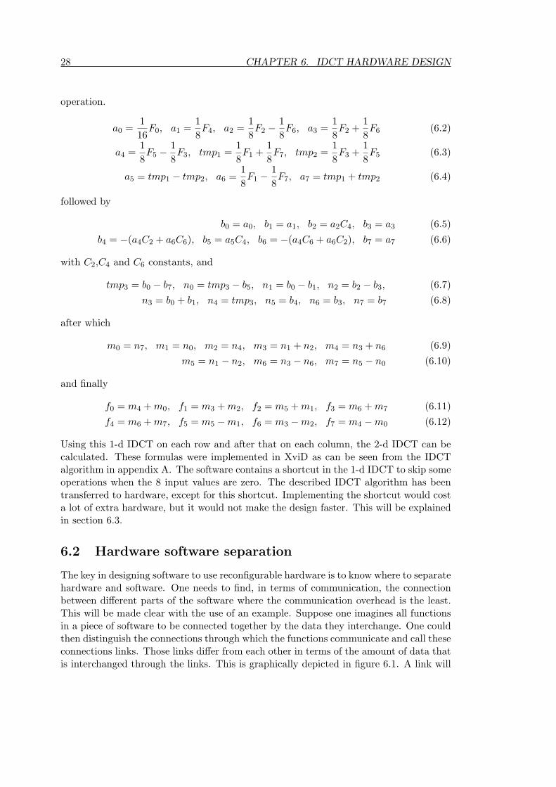
The second and most relevant function called from xvid_decraw is the functiondec_main() This is the function that actually decodes a frame from the source bitstreamand outputs the decoded images. After the decoding of the last image, xvid_decrawwill know from dec_main() that all frames are decoded. The third function is the onewhich tells XviD to clean up the memory used for decoding when it has finished, isdec_stop(). The source of the example program calling these functions can be foundin appendix B.

The XviD decoder evaluation 5The motivation for choosing the XviD codec has been made clear in chapter 4. Section5.1 will examine the source code of the XviD codec. The profiling of the XviD codec iselaborated on in section 5.2. Section 5.3 will explain how these profiling results will beused in the process of speeding up the XviD codec.
5.1 Exploring the XviD source code
As stated in section 4.4 the XviD codec can be used from within a program to decodeMPEG-4 video, by calling functions from the XviD library. This XviD library thenhas to be compiled and linked together with the program. The three functions that arecalled from the example program have been explained. This section will elaborate on thefunctions worth noting for speeding up the decoder. The function which is important forthis project is the function decoder_mb_decode(). It operates on the MPEG-4 bitstreamfrom an MPEG-4 file and it uses quantisation matrices which have been generated duringthe initialisation of the decoder. The mentioned decoding function contains several otherfunctions operating on the data one after another.
First a macro-block of encoded data is retrieved from the bitstream containing up to 6blocks of data. This is done by the function get_inter_block() or get_intra_block()depending on the type of frame currently decoded (P-, B- or I frame). After retrievingthe values they are de-quantised. As mentioned in chapter 3, values are quantised whenencoding, so they need to be de-quantised when decoding. On the resulting values theInverse Discrete Cosine Transform (IDCT) is performed by the function idct_int32().This is done for each of the 6 blocks of 8x8 pixels in the macro-block. On the resultingimage a colourspace conversion is performed after which the image is returned. Thesource code of the decoder functions is listed in appendix E.
In section 5.2, the decoder will be profiled to determine which functions require themost computation time. Section 5.3 will discuss the speeding up of the XviD decoder.In chapter 6 the hardware to speed up XviD is designed. This chapter will explain thatthe IDCT will be migrated to hardware. The parent function decoder_mb_decode()calling the IDCT and the functions before and after the IDCT will be too large to moveto hardware entirely.
5.2 Profiling the XviD codec
To determine the computation intensive parts that would benefit the most from movingto hardware, the codec needs to be examined and profiled. In section 5.1, the XviDcodec source was examined. Initial exploration of the codec was done on an x86 Linux
23

24 CHAPTER 5. THE XVID DECODER EVALUATION
platform. The profiling of the codec to determine the computation intensive kernels willbe described in subsection 5.2.1. Cross-compilation of the codec to the ARM platform isdescribed in subsection 5.2.2. Finally, the maximum obtainable speedup for the chosenkernels is calculated in section 5.3.
5.2.1 Profiling the codec on the PC
As explained in section 4.3 the XviD codec was compiled for the x86 platform. To enablethe profiling of the XviD codec, the example source code provided with the XviD codecwas modified, as explained in section 4.4. This example code, xvid_decraw as listedin appendix B, was compiled with profiling turned on in the compiler switches. Theseswitches tell the compiler to include profiling functions which enable the user to gaininformation about the time spent in each function during the operation of the program.When running the generated executable, a file gmon.out is created that contains saidtiming information. This gmon.out file can be read by a profiler program, in our casegprof, to generate human readable information as to which functions use the most time.A summary of the results of this profiling is shown below.
% cumulative self self totaltime seconds seconds calls ms/call ms/call name26.92 0.43 0.43 67 6.44 6.44 yv12_to_bgr_c19.73 0.75 0.32 167121 0.00 0.00 idct_int328.40 0.88 0.13 90615 0.00 0.00 get_inter_block6.46 0.99 0.10 136681 0.00 0.00 transfer8x8_copy_c.....
The entire profiling result can be found in appendix C. As can be seen from theseresults the colourspace conversion yv12_to_bgr_c and the IDCT idct_int32 take upthe largest amount of execution time.
5.2.2 Cross-compilation for the DAMP platform
After compilation on the PC, the XviD codec was compiled for the DAMP platform.The first noticeable difference when running the decoder, was the time needed for ini-tialisation. Due to the slower memory interface on the DAMP platform, initialising thecodec took a considerable amount of time. Initialisation of XviD on the DAMP platformlasted about half a minute, while it lasted only about a second on the PC. When againcompiling the codec with profiling turned on, the initialisation function of the XviD de-coder indeed took most of the time. The initialisation function will not take much timefor larger files, because it is only performed once when starting the decoding process.Therefore, its influence can be disregarded for determining which kernel will be spedup. The reason that initialising takes so much time, is because the DAMP platform hascertain limitations in communication speed to memory. It is expected that on futureversions of the DAMP platform the time needed for the initialisation is less noticeable.After the initialisation function, the colourspace conversion and the IDCT directly fol-lowed with respect to time usage. When disregarding the initialisation function, the

5.3. SPEEDING UP THE CODEC 25
colourspace conversion and the IDCT are considered the most time consuming, like onthe PC. Section 5.3 will explain how the decoder will be sped up.
5.3 Speeding up the codec
Tests on the ARM platform when skipping the IDCT function show considerablespeedup. So the IDCT is responsible for a large part of the time on ARM as well. Forthe colourspace conversion, the same argument holds valid. When colourspace conver-sion is disabled in XviD, the decoding speeds up considerably. These speedups indicatethe maximum obtainable speedup. The frame decoding times have been acquired byaveraging the decoding times of four reference video files and outputting them using theVGA controller. This has been done several times for different settings. The results aresummarised in table 5.1.The speedup is defined as the factor between the old computation time and the new
SW IDCT SW colourspace Time per frame maximumenabled conversion enabled speedup
Yes Yes 445.9 ms 1.0No Yes 341.1 ms 1.31Yes No 362.6 ms 1.23No No 261.5 ms 1.70
Table 5.1: Average decoding time of MPEG-4 files while selectively disabling the IDCTor the colourspace conversion and maximum obtainable speedup
computation time. It can be calculated by dividing the old computation time by thenew computation time. If the new computation time is smaller, the speedup is largerthan one. It can be formulated as
S =Toriginal
Taccelerated(5.1)
which is a simplified version of Amdahl’s law for speedup due to parallelising. Whendisabling only the colourspace conversion, a speedup of 1.23 is the maximum, while dis-abling only the IDCT would generate a maximum speedup of 1.31. This document willdescribe the design of hardware to speed up the IDCT. The reader is referred to [13] forthe design of the hardware to speed up the colourspace conversion.
The chosen XviD codec will be enhanced to make use of the re-configurable hard-ware available on the DAMP platform. A certain type of MPEG-4 decoding of lowresolution video on ARM-based devices, such as several mobile phones, has already beendone without the use of reconfigurable hardware [1]. One is to expect that the DAMPimplementation will be able to decode low resolution video as well. It is conceived thatre-configurable hardware can be used to speed up similar devices which are using MPEG-4. Preliminary tests show that this version of the DAMP platform is not able to decodeMPEG-4 video in real time. The current version of DAMP accesses 16 bit words frommemory at 12.5 MHz. Frame-rates of the decoded files vary between 3 to 5 fps (framesper second). On hand held devices a frame-rate of 10 to 15 fps is acceptable. Future

26 CHAPTER 5. THE XVID DECODER EVALUATION
versions of the DAMP platform should be able to access the memory at several timeshigher speeds. Therefore real-time decoding of video files on DAMP is expected to befeasible for mentioned frame-rates. The design of the hardware to aid in the calculationof the IDCT is described in chapter 6.

IDCT hardware design 6As stated in section 5.2, the Inverse Discrete Cosine Transform (IDCT) is responsible fora considerable part of the decoding time of the MPEG-4 video. Therefore implementingit in hardware (an FPGA) could support the MPEG-4 decoding by performing theIDCT faster. The IDCT kernel will be implemented in hardware as a co-processor.The hardware kernels will be designed as fixed kernels instead of using an arbiter tointercept instructions meant for the hardware, like in the MOLEN paradigm [25].
In section 6.1, the IDCT algorithm is described. The separation between hardwareand software will be described in section 6.2. The considerations for the implementationof the IDCT are made in section 6.3. Section 6.4 will elaborate on the performance ofthe hardware. The modifications made to XviD are described in section 6.5. The designof the colourspace conversion hardware kernel and considerations on using an arbiterhave been described in [13].
6.1 Inverse Discrete Cosine Transform
In this section the IDCT algorithm used in XviD is explained. The C source codeimplementation of this algorithm can be found in appendix A. The IDCT is the inverseoperation of the Discrete Cosine Transform (DCT). The 2-dimensional DCT [26] is shownin equation 6.1.
Suv =14CuCv
7∑x=0
7∑y=0
sxy cos(2x + 1)uπ
16cos
(2y + 1)vπ
16(6.1)
with Cu,Cv = 1√2
for u, v = 0; Cu,Cv = 1 otherwise.This equation can be divided into two parts. These parts are performed after each other,consisting of eight 1-dimensional DCT operations. Such a 1-d DCT operates on eachcolumn with y constant and on each row with x constant. The 1-d DCT can be rewritteninto a matrix multiplication. The inverse operation, the IDCT, can then be obtainedby inverting the matrix. This inverted matrix can be factored into multiple sparsematrices. Because the matrices are sparse1, these subsequent matrix multiplications canbe replaced by a small amount of scalar operations. This way the following sequenceof operations results, as documented in [16], with F0 through F7 the values of each rowor column before the IDCT operation and f0 through f7 the values resulting from the
1Sparse matrices contain few non-zero elements. In sparse matrix multiplications most operationsconsist of multiplying by zero, leaving only a few relevant operations.
27
28 CHAPTER 6. IDCT HARDWARE DESIGN
operation.
a0 =116
F0, a1 =18F4, a2 =
18F2 −
18F6, a3 =
18F2 +
18F6 (6.2)
a4 =18F5 −
18F3, tmp1 =
18F1 +
18F7, tmp2 =
18F3 +
18F5 (6.3)
a5 = tmp1 − tmp2, a6 =18F1 −
18F7, a7 = tmp1 + tmp2 (6.4)
followed by
b0 = a0, b1 = a1, b2 = a2C4, b3 = a3 (6.5)b4 = −(a4C2 + a6C6), b5 = a5C4, b6 = −(a4C6 + a6C2), b7 = a7 (6.6)
with C2,C4 and C6 constants, and
tmp3 = b0 − b7, n0 = tmp3 − b5, n1 = b0 − b1, n2 = b2 − b3, (6.7)n3 = b0 + b1, n4 = tmp3, n5 = b4, n6 = b3, n7 = b7 (6.8)
after which
m0 = n7, m1 = n0, m2 = n4, m3 = n1 + n2, m4 = n3 + n6 (6.9)m5 = n1 − n2, m6 = n3 − n6, m7 = n5 − n0 (6.10)
and finally
f0 = m4 + m0, f1 = m3 + m2, f2 = m5 + m1, f3 = m6 + m7 (6.11)f4 = m6 + m7, f5 = m5 − m1, f6 = m3 − m2, f7 = m4 − m0 (6.12)
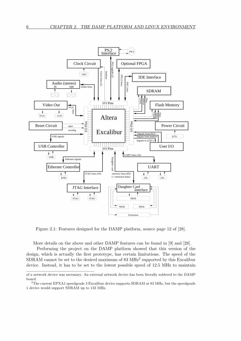
Using this 1-d IDCT on each row and after that on each column, the 2-d IDCT can becalculated. These formulas were implemented in XviD as can be seen from the IDCTalgorithm in appendix A. The software contains a shortcut in the 1-d IDCT to skip someoperations when the 8 input values are zero. The described IDCT algorithm has beentransferred to hardware, except for this shortcut. Implementing the shortcut would costa lot of extra hardware, but it would not make the design faster. This will be explainedin section 6.3.
6.2 Hardware software separation
The key in designing software to use reconfigurable hardware is to know where to separatehardware and software. One needs to find, in terms of communication, the connectionbetween different parts of the software where the communication overhead is the least.This will be made clear with the use of an example. Suppose one imagines all functionsin a piece of software to be connected together by the data they interchange. One couldthen distinguish the connections through which the functions communicate and call theseconnections links. Those links differ from each other in terms of the amount of data thatis interchanged through the links. This is graphically depicted in figure 6.1. A link will

6.2. HARDWARE SOFTWARE SEPARATION 29
Figure 6.1: Thinnest links in terms of communication between functions.
be called thick when a lot of data is sent through it and thin when a limited amount ofdata is sent through it. This classification is utilised to order the different links.
The likely locations to make the hardware software separation are on those thinlinks.When there are several thin links, the best approach would be to choose the largestpart that fits the hardware. Depending on the size of the reconfigurable hardware, largerparts of the software can be put into hardware.
When device size is limited, large parts of software cannot be put into hardware asa whole. This produces sub-optimal results compared to when the largest part with thesmallest communication overhead is implemented in hardware. In our case, the part thatwill be put into hardware is determined by several properties. For instance its weight inexecution time, where a large weight means the function is responsible for a large partof the execution time. Keeping that in mind, the part that is to be put into hardwareneeds to fit into the device. The part with the least communication overhead is to befound. The smallest amount of data would have to be transferred, when the encodedbitstream would be sent directly to the hardware. In figure 6.1 that would be the caseif the function ”main”, and all the functions in it, were to be put in hardware entirely.Then if the hardware would also control the VGA connection, data would only have tobe sent back to the decoder if the decoded frames are to be stored on the DAMP board.Naturally putting the entire decoding of the bitstream in hardware would require muchmore hardware than only computing the IDCT and it would become too large to beimplemented. Therefore the function expected to have the greatest speedup, which stillfits into the FPGA has to be implemented. Depending on the size of the FPGA differentfunctions could be valid candidates.
The relative amount of data to be transferred to hardware for each frame generallybecomes less when the function implemented in hardware becomes more complicated.Also there is an upper limit on the amount of data that can be transferred to hardware at

30 CHAPTER 6. IDCT HARDWARE DESIGN
once, depending on the way the hardware and software communicate. This will becomeclear in section 6.3.1. As explained in that section, the size of the DPRAM will be thefactor limiting the amount of data that can be transferred.
In this case, it turns out that the IDCT and the functions calling it are responsible fora large part of the execution time. The IDCT itself has such a large size in hardware thatimplementation of other large functions, besides the colourspace and IDCT, in hardwareas well is not an option. This will become clear in section 6.3 where the IDCT datapathis designed.
6.3 Hardware implementation
When implementing the IDCT in hardware to aid the software to perform its functionfaster, several considerations have to be made. This section will describe the design ofthe IDCT hardware accelerator for the modified XviD codec.
First, the accelerator should enable the software to function as it did without hard-ware, showing no noticeable differences. The hardware IDCT should return the samevalues as would the software version. This can be tested by using a large amount ofreal test values and comparing the result of both implementations. Secondly, the IDCTshould fit in the available hardware.
The designed IDCT hardware will be combined later with another piece of hardwareto be able to control the VGA periphery and speed up the colourspace conversion [13].This piece of hardware will be designed to take up less then 25% of the FPGA thus leav-ing over 75% for the IDCT hardware. Of course another constraint is that the hardwareshould speed up the entire calculation. The hardware should be able to finish and giveback the results to the software, in a much shorter time than originally needed for thesoftware. When designing the hardware, the amount of time needed for communicationwith the software should be kept as small as possible. Subsection 6.3.1 will decide onthe way to communicate between hardware and software.
6.3.1 Hardware and software communication
The hardware part should remain functionally equivalent to the software, withoutnoticeable differences (except for speed). It should fit in the available reconfigurablehardware and it has to be combined with the hardware to speed up the colourspaceconversion. Apart from these constraints, the overhead in time needed for communica-tion between the hardware and the software should be kept as small as possible.
To keep the communication overhead low, an efficient communication method isrequired. One IDCT requires 128 bytes to be exchanged2 between hardware andsoftware. In order to speed up the calculation, the transfers of the data and theIDCT operation in hardware need to be faster than the original software. In eachclock cycle the maximum possible amount of data needs to be exchanged to keep thecommunication penalty low.
When exploring the ways for the ARM CPU to communicate with the FPGA, several2Before the IDCT operation, 128 bytes need to be transferred to the hardware and when the IDCT
has been calculated, 128 bytes should be transferred back.

6.3. HARDWARE IMPLEMENTATION 31
options are to be evaluated. There is one GPIO (General Purpose Input and Output)register available for communication between the CPU and the FPGA. However, onthis version of the Excalibur, only 4 output and 4 input pins are available, making thismethod of communication unattractive for large amounts of data, since only 4 bits canbe sent each cycle. In this case transferring 256 bytes would take 512 cycles supposingeach transfer uses one cycle (which actually will be more because of handshaking).
Another way of communicating with the hardware would be to use the AMBA busand make the hardware in the FPGA a slave on that bus. The AMBA bus is a highspeed 32 bit bus available in the Excalibur for connecting different devices. There isone AMBA bus, the AHB1 bus (AMBA High-speed Bus 1), operating at the samespeed as the ARM CPU and another one, the AHB2, operating at half that speed. Forcommunication, the CPU could use the AHB1 and connect to the AHB2 via a bridgeand then connect to the FPGA. However, this would require the IDCT hardware to beable to communicate via the AMBA bus, causing extra overhead and increasing the sizeof the FPGA design. Apart from that, an option using only the high speed AHB1 businstead of both the AHB1 and the AHB2 bus would be preferred.
A third option would be to use a DMA controller inside the FPGA to copy thedata needed for the IDCT from memory accessible by the CPU, into a local memoryon the FPGA. However this inhibits the same contra arguments as does the previousoption. In this case as well, the AHB2 bus would be used for communication of theDMA controller in the FPGA with the memory. This would cause extra overhead onthe communication and on the hardware size.
The best remaining option would be to use the available dual-port RAM (DPRAM),which is accessible by the CPU as well as by the FPGA. It does not require extrahardware inside the FPGA and it does not cause much communication overhead forthe hardware as well. The CPU communicates with the DPRAM via the AHB1 bus,as it does with all periphery. In that respect, this is not a disadvantage compared tothe other options. The FPGA has direct access to the DPRAM. A limitation of thisapproach could be the limit on the amount of data that can be transferred each time.Fortunately this is not a limitation, since for one IDCT only 128 bytes need to beexchanged.
The DPRAM is 16 Kbytes, so it is large enough for the data of 128 IDCT kernels.One IDCT will be performed each time, after which the results will be needed for thecontinuation of the MPEG-4 decoder. If in the future one would change the behaviour ofthe MPEG-4 codec to enable the pipelined computation of several IDCTs, this approachwould enable one to store the results of 128 IDCTs (16 Kbytes) simultaneously in theDPRAM.
Pipelining the total IDCT operation to have the new input for the next IDCTwritten to DPRAM while calculating the current IDCT has two prerequisites. First, itwould require the IDCT hardware to perform its operation within the time needed forthe software to put the next 128 bytes in the DPRAM. In that case the time needed forcommunicating the data would be less than the time needed for the hardware to finishcomputing. As will become clear in section 6.4 this is not the case. Secondly, it wouldrequire the existence of multiple IDCT cores in the FPGA to handle the larger amountof data, which would in turn require a larger FPGA than the one currently available on

32 CHAPTER 6. IDCT HARDWARE DESIGN
the DAMP board. The design of the IDCT hardware will be explained in subsection 6.3.2.
6.3.2 IDCT hardware implementation
In the software the IDCT is calculated by first performing an operation on each rowof the 64 value matrix and then performing an operation on each column of the re-sulting values. The row operations can be performed independently of each other, butare performed before the column operations. The column operations can each be per-formed independently as well. When examining the code used by the MPEG-4 decoderto perform the IDCT, one can recognise there are only subtle differences between theoperations performed on the rows and those performed on the columns. This gives rise tothe possibility of designing a piece of hardware capable of performing a row operation ora column operation when requested to do so. Depending on the size of such a functionalunit, control logic could use one or more of them to compute the IDCT.
A functional unit capable of computing only mentioned row operation was designedin hardware using Quartus II from Altera. It would take up about half of the available4160 cells in the FPGA. Therefore the idea of creating more than one IDCT core to workin parallel was abandoned. When augmenting the functional unit to perform the columnoperation as well, about two third of the FPGA was covered. The number of cells usedfor the unit operating on rows or columns only and for the unit selectively operating onrows or columns is depicted in table 6.1.
Type of unit number of cells in the FPGA percentage of the chiprow-only unit 2030 cells 48%
column-only unit 2361 cells 56%row/col unit 2771 cells 66%
Table 6.1: Cell usage of the EPXA1 device for the row-only, column-only and row/colunit
In figure D.1 in appendix D the design of this hardware piece is depicted. Thisfunctional unit will be called the row/col unit from now on. Using this row/col unitadditional control logic is needed to load the appropriate row or column into the unitand to store the results of the row operations to be used by the column operations beforewriting back the results. The FPGA is capable of reading 32 bits at a time out of theDPRAM. One row contains 8 values of 16 bits, so four read operations from the DPRAMare needed before the row operation can be performed. Initial simulation tests of therow/col unit showed that results of the operation are available within 100 ns. In order tohave the next 16 bytes of data ready in time, the four read operations from the DPRAMneed to be performed in 100 ns to keep the row/col unit busy, since one does not wantthe unit to be idle.
Tests show that a 32 bit word from the DPRAM can be read out by the hardware inone clock cycle when operating at 50 Mhz. Initial designing was done for 40 Mhz whichwas expected to be just enough to keep the row/col unit computing all the time. Furthertesting shows that the row/col unit has less latency than earlier simulations indicated.

6.3. HARDWARE IMPLEMENTATION 33
Figure 6.2: Datapath of the implemented IDCT with row/col unit.
Instead of after 100 ns the unit is ready after 75 ns. After verifying the correct operationat 40 MHz, the design has been setup to operate at 50 MHz. This frequency is the highestat which the design still fits into the device. Quartus is unable to fit the design for clockfrequencies higher than 50 MHz, because higher frequencies imply stricter limitations onrouting. Section 6.3.3 will elaborate on this.
The values the row/col unit is operating on are stored in registers to pipeline thedesign. Pipelining enables the new values to be made available to the row/col unit atthe same time as the previous results are stored. The results from the row operations arestored into an internal memory on the FPGA and later fed back into the row/col unit toperform the row operations on. After each column operation, the results are stored backinto the DPRAM. When the IDCT is finished, the CPU should be notified. For resettingthe IDCT hardware and for notifying the CPU when the IDCT has completed, the GPIOregister will be used. Using the GPIO enables the hardware to get a logic signal from theCPU directly. No extra cycle is needed to read a value from the DPRAM at the startand no extra hardware is needed to convert this value into a start or reset signal. Thesignal from the GPIO can be used directly to signal a reset. The data exchange will usethe DPRAM, because it can be read out 32 bits at a time, but for signalling the GPIOregister is used, as explained in subsection 6.3.1.
The designed datapath and the control logic (the ”FSM” block) are shown in figure6.2. In this figure the FSM is a finite state machine, written in VHDL (a HardwareDescription Language used by Quartus), to control the registers and the communicationwith the DPRAM. In the depicted datapath data flows through the row/col unit 16times. First 8 row operations are performed, secondly 8 column operations. In orderto do this, the FSM sets the correct address for the DPRAM and enables the registersto load the data coming from the DPRAM. After 4 reads from the DPRAM a secondstage of registers is enabled to load in the 4 words from the first stage at once. Whilethe row/col unit is computing the IDCT of the read values, the next input values willsimultaneously be read into the registers of the first stage. When the row/col unit isfinished, the FSM enables the registers at the output of the row/col unit to read in,simultaneously with the second stage of registers at the input of the row/col unit. Therow/col unit is now calculating the IDCT of the second row, while the FSM is controlling

34 CHAPTER 6. IDCT HARDWARE DESIGN
Figure 6.3: States of the FSM controlling the IDCT datapath.
the internal DPRAM to store the values from the register at the output. This process isrepeated for the other rows. When the IDCT of the columns needs to be calculated, theinput of the first stage of registers is switched to read from the internal DPRAM insteadof the normal one.
Further on the FSM roughly repeats the steps previously mentioned, but this time therow/col unit is operating on the previously calculated values coming from the DPRAMinternal to the FPGA. Finally after each row/col operation the values are now writtenfrom the internal DPRAM to the normal DPRAM. A bit in the GPIO register is setby the FSM to signal that the IDCT has been calculated. It should be noted thatthe described process takes up much less time than the communication time from thesoftware to the DPRAM. The hardware IDCT will be ready before data for a next IDCTwould be written to the DPRAM. As long as the communication takes more time thanthe calculation, only one core will be needed. Even when pipelining IDCT operationsthe communication would still keep the row/col unit waiting for data.This will becomeclear in section 7.2. The previously described operation of the FSM is depicted in figure6.3. All the signals generated by the FSM for controlling the datapath can be found infigure D.4 in appendix D.
As mentioned in section 6.1, the software contains a shortcut to deliver the valuesof the 1-d IDCT on a row or column faster. This would not make sense for the hardwareversion, because it would require much more hardware, but the result would be the same.The hardware would not benefit from the row/col unit being ready earlier, since newinput values are only available every 80 ns with a 50 MHz clock signal. Even if theIDCT hardware could have been sped up by the shortcut, it would not be implementedfor two reasons. First, the hardware would become much bigger, while the IDCT andthe colourspace conversion only barely fit without it. Secondly, the time needed forthe hardware IDCT is very small compared to the time needed for the communicationbetween hardware and software.

6.3. HARDWARE IMPLEMENTATION 35
Section 6.4 will go into detail on the performance of the described datapath. Thedesign of the hardware for speeding up the colourspace conversion and for controllingthe VGA interface is described in [13]. The IDCT hardware will be combined with thehardware for the VGA driver and the colourspace conversion to fit together in the FPGA.The fitting of the design is explained in subsection 6.3.3.
6.3.3 Fitting the design into the FPGA
The designed IDCT hardware had to be combined with the hardware for the colourspaceconversion and the VGA controller. Both hardware pieces have been designed separately.The design of the colourspace conversion hardware is presented in [13]. The IDCThardware used 3218 logic cells of the available hardware and the colourspace hardwareand VGA controller used 1284 logic cells. The total amount of available logic cells is4160. It therefore seems that the two designs cannot be combined. However, the Quartustools can try and merge logic cells from the two designs together when possible. Quartuscan be configured to optimise the design for area or speed. Optimising for speed createsa design that should work, but is too large to fit into the EPXA1 device. Optimisingfor area creates a design that is small enough, but several signals cannot be routed tomeet the speed requirements of the 50 MHz clock signals. The global settings used toconfigure Quartus optimisation are as stated below. Global optimisation has been setfor speed. The settings which differ from the standard settings are listed.
• Optimisation technique set to speed.
• Auto global memory control signals set to on.
• Auto implement in ROM set to on.
• Auto packed registers set to minimise area.
• Remove redundant logic cells set to on.
Different parts of the design have been set to be optimised for area, overruling the globalsettings to optimise for speed. The global setting for speed optimisation has been turnedon to maintain correct system functionality, but for each part of the design where speedwas not critical, optimisation for area has been set.
Configured this way, the Quartus tools were able to compile and fit the design intothe EPXA1 device. However, the routing of all the signals still was a problem for thetools, because of the requirements for clock speed. When evaluating the clock signals,one signal was used to drive several registers. These registers loaded the result of therow/col unit to pipeline the operation, as mentioned in subsection 6.3.2. The speed ofthe clock signal driving these registers was originally set to 80 MHz. This was becauseit was expected that changes at the input of the row/col unit would propagate quicklyto the output. Tests have shown that the outputs of the row/col unit remain as theywere for over 20 ns, so the constraint could be relaxed. Therefore the clock signal forthe pipeline registers of the row/col unit could operate at 50 MHz. A 50 MHz clock hadbeen used for the colourspace conversion as well, so the same clock signal could be used.This loosened up the constraints and enabled the Quartus tools to generate a working

36 CHAPTER 6. IDCT HARDWARE DESIGN
Figure 6.4: Simulation of several signals from the FSM controlling the IDCT datapath.
design containing both the IDCT hardware and the VGA controller with the colourspaceconversion.
6.4 Hardware performance
The FSM controlling the IDCT hardware cycles through a similar sequence of events 16times. First the row operations have to be performed on the input data, 8 rows aftereach other, then the 8 column operations have to be performed. The waveform showingall the signals originating from the FSM is shown in figure D.4 in appendix D. Figure 6.4shows the reset, the row0col1, the sel_input and the done signal. As one can see fromthe signal row0col1 the first half of the operations is on the rows and the second halfis on the columns. The signal sel_input is a similar signal. It controls the multiplexerfrom figure 6.2 to select whether to read from the DPRAM or from the internal memory.The DPRAM contains the values to perform the row operations on and the internalmemory contains the results of that operation, on which the column operation is to beperformed.
The cycle time for one full IDCT operation can be derived from figure 6.4. The timerequired from the moment the input values are available until the output values are ready,is 2.98 µs. This is the time for the hardware IDCT without the time required for thesoftware to store the values in the DPRAM and to read out the results. Therefore timefor communicating with the software will have to be added. On this version of the DAMPboard the maximum clock speed of the IDCT hardware is 50 Mhz, because of the speedgrade 3 of the Excalibur device. In future designs a higher clock frequency could shortenthe cycle time of this FSM, but even more important, on future versions of the DAMPboard the communication overhead would be less. The time needed for exchanging theresults on this version of DAMP is far longer than the time for the hardware to calculatethe IDCT. The total cycle time for the IDCT in software compared for the one usinghardware will be stated in chapter 7 which will discuss the results of the implementationin hardware.

6.5. XVID MODIFICATION 37
6.5 XviD modification
The original source code for the calculation of the IDCT is shown in appendix A. TheXviD code has been modified to enable the user to select whether to calculate theIDCT using hardware or to use the software only approach. The initialisation func-tion dec_init() of the XviD decoder initialises the settings that are to be used fordecoding. A global variable was added to tell the IDCT function whether or not to usethe hardware. The piece of source code calling the IDCT function in XviD is shownbelow. The entire source code of the decoder is listed in appendix E.
start_timer();if (USE_HARDWARE) {
us_hardware_idct_ioctl(data,data); //the added function//copying the values to the DPRAM// and reading out the results:// us_hardware_idct(destination,source);
} else {idct(data);
}stop_idct_timer();
The start_timer() and stop_idt_timer() functions can be used to measure thetime spent in the IDCT. They are normally disabled when decoding. The functionus_hardware_idct_ioctl() uses the Linux driver to communicate with the hardware.As can be seen the if statement determines whether or not to use the hardware. Theglobal variable USE_HARDWARE has been set in the dec_init() function as explained insection 4.4. The driver for the IDCT is a modified version of the VGA driver. TheVGA driver uses the SRAM to store images to be displayed, while the IDCT driver usesthe DPRAM to store values on which the IDCT is to be performed and uses the GPIOregisters to control the IDCT hardware. The design of Linux drivers is described in [13].

38 CHAPTER 6. IDCT HARDWARE DESIGN

Experimental results 7The test-results described in section 5.3 showed the theoretical maximum speedup whenusing infinitely fast hardware accelerators. The current chapter will describe the meth-ods applied for measuring the actually obtained speedup. Section 7.1 will explain themethods used to measure the change in speed of the decoding process. Section 7.2 willelaborate on the results obtained by using hardware acceleration and compare thoseresults with the theoretical maximum speedups.
7.1 Measuring methods
To measure the performance influence of the implemented hardware IDCT andcolourspace conversion on XviD, the program xvid_decraw discussed in section 4.4 hasbeen modified. It measures the time needed for the decoding and displaying of each videoframe. The decoding time of the ”software only” version of XviD has been measured,as shown in section 5.3. After implementation of the IDCT and the colourspace conver-sion in hardware, similar measurements have been performed with hardware accelerationturned on.
Four MPEG-4 test sequences have been generated using files available from the Tech-nical University in Munich [10]. We will use these test sequences as benchmarks in thissection. The MPEG test sequences have been used to measure the time needed for dif-ferent configurations of XviD to decode the video content. Six different configurationshave been used to decode each of the four files.
The first and most straightforward configuration is the software only version of XviDrunning on DAMP. In the second configuration, the call to the IDCT function is in-tentionally skipped to acquire the theoretical maximum possible speedup for the IDCT.Such a speedup would be obtained in a hypothetical case of using infinitely fast hard-ware with no software-hardware communication overhead. For this configuration, thecolourspace conversion was performed in software. The maximum speedups shown in sec-tion 5.3 are depicted in table 7.1. The third configuration is the one using the hardware
SW IDCT SW colourspace Time per frame maximumenabled conversion enabled speedup
Yes Yes 445.9 ms 1.0No Yes 341.1 ms 1.31Yes No 362.6 ms 1.23No No 261.5 ms 1.70
Table 7.1: Average decoding time of MPEG-4 files while selectively disabling the IDCTor the colourspace conversion and maximum obtainable speedup
39

40 CHAPTER 7. EXPERIMENTAL RESULTS
kernel to calculate the IDCT, still with the colourspace conversion in software. Fromthe measurements with these three configurations, the time needed for the software andhardware IDCT operations will be derived by subtracting the time for XviD with ”noIDCT” from the two remaining time measurements.
Apart from the mentioned three measurement configurations (software IDCT, hard-ware IDCT and ”no IDCT”) three similar measurements have been performed, with thecolourspace conversion performed in hardware instead of software. The results of theabove six different configurations will be compared to draw conclusions for the totalspeedup due to the hardware accelerations. For details about the colourspace conver-sion hardware implementation the reader is referred to [13]. Section 7.2 will discuss theresults of the measurements and explain the derivation of the time required for a singlehardware and software IDCT calculation.
7.2 Acquired results
The measurement results from section 7.1 are discussed in subsection 7.2.1. Thespeedup of the total application is calculated from these measurements in subsection7.2.2. From the measurements on the total application, the operation time of the IDCTkernel implementation is derived in subsection 7.2.3. In subsection 7.2.4 the expectedspeedups on future DAMP versions are discussed.
7.2.1 Measurements
As described in section 7.1, six different configurations have been used to decode fourMPEG-4 test sequences. In all six cases the video frames are decoded and displayedusing the VGA controller. Figure 7.1 shows the decoding time per frame for the decodedreference files. The leftmost three columns indicate the times needed for XviD usingsoftware colourspace conversion while varying the IDCT configuration. For the rightthree columns, the hardware colourspace conversion was used while varying the IDCTconfiguration. Each reference file contained 20 frames of MPEG-4 video. Differences indecoding time between the reference files are due to each file requiring a different numberof IDCT operations. The average decoding time per frame is stated in table 7.2.
7.2.2 Speedup calculation
The average decoding time for a frame as shown in table 7.2 can be used to calculatethe average speedup compared to the software only approach. The average speedupscompared to the configuration using only software, can be calculated resulting in thevalues which are graphically depicted in figure 7.2. For the calculation of the speedup asimplified version of Amdahl’s law for speedup due to parallelising is used. The speedupis defined as the factor between the old computation time and the new computationtime. It can be formulated as:
S =Toriginal
Taccelerated=
445.86396.65
= 1.12 (7.1)

7.2. ACQUIRED RESULTS 41
Figure 7.1: Average decoding time per frame for four reference MPEG-4 files measuredfor six different configurations of IDCT and colourspace conversion (CSPC).
configuration total time per framesSW IDCT, SW colourspace 445.86 ms using IDCTSW IDCT, HW colourspace 362.64 ms in softwareno IDCT, SW colourspace 341.07 ms the upperno IDCT, HW colourspace 261.53 ms limitHW IDCT, SW colourspace 396.65 ms using IDCTHW IDCT, HW colourspace 317.93 ms in hardware
Table 7.2: Average decoding time per frame
Thus a speedup of 1.12 for the application due to the hardware IDCT is obtained.
7.2.3 IDCT operation time
The speedup of 1.40 from figure 7.2 for the total decoding process is the one actuallyobtained when performing both IDCT and colourspace conversion in hardware. Thesix measured values from table 7.2 are the times needed to decode one frame. Pleasenote that for each frame several IDCT operations are required. Comparing the framedecoding time with ”no IDCT” and the time with software IDCT gives the time neededfor the software IDCT operations in a frame. Similarly comparing the frame decodingtime using the hardware IDCT and the one using ”no IDCT” yields the time needed forthe hardware IDCT operations. This results in the values of table 7.3 for the time spentin the IDCT function when decoding one frame. Please note that these values will be

42 CHAPTER 7. EXPERIMENTAL RESULTS
Figure 7.2: Average relative speedups for six different configurations of IDCT andcolourspace conversion (CSPC).
used in subsection 7.2.4 to predict future speedups. By dividing the IDCT operationtime per frame from table 7.3 by the number of IDCTs for each frame, the time of asingle IDCT kernel execution can be calculated.
IDCT operationtime per frame
using software IDCT 103 msusing hardware IDCT 56 ms
Table 7.3: Average IDCT operation time per frame.
The total average software and hardware IDCT time can now be calculated as wellas the time needed for the communication with the hardware. The time needed forthe hardware operation is known from the simulation in section 6.4 and is 2.98µs. Themeasured operation time of the hardware IDCT is 180µs. Therefore the communicationtime from software to hardware and back is determined to be 177µs. One software IDCToperation uses 334µs. The speedup can now be calculated:
S =Toriginal
Taccelerated=
334180
= 1.86 (7.2)
These values are stated in table 7.4. The colourspace conversion has been acceleratedby a factor of 3.59 as explained in [13].

7.2. ACQUIRED RESULTS 43
Total average time per IDCTSW IDCT total operation time 334 µsHW IDCT total operation time 180 µs
hardware kernel time 2.98 µshardware communication time 177 µs
Average speedup of the IDCT kernel 1.86
Table 7.4: Total average time per IDCT for software and hardware and calculatedspeedup of the kernel for each file.
7.2.4 Improving hardware IDCT speed
As calculated in subsection 7.2.3 the total application has a speedup of 1.12 when theaccelerated IDCT kernel is used. The upper limit for the speedup of the total applicationis 1.31 when the IDCT kernel would be infinitely fast. This leaves a margin for the IDCTkernel to be improved. Currently one total hardware IDCT operation requires 180 µsas indicated in table 7.4. The communication time for this hardware IDCT to load theinput values and to store the results was determined to be 177 µs. It is expected thatthis communication time can be decreased on future versions of the DAMP platform.The reason that the processor needs so much time to present the values to the hardwareis because it needs to read these values from the SDRAM. The current communicationspeed to the external SDRAM is 12.5 MHz. On future versions it is expected that thisspeed can be increased to 133 MHz. In the most optimal case the communication timeof 177 µs would therefore be decreased to less then 17 µs. Adding the 2.98 µ neededfor the hardware excluding communication time, this would make the total hardwareoperation time 20 µs. The speedup of the IDCT kernel in this case would become:
S =Toldhardware
Tfasterhardware=
18020
= 9 (7.3)
Using the values from table 7.3 we can predict what the time needed for the hardwarewould be with this speedup. The time the application spends performing IDCT functionsfor one frame, is expected to decrease 9 times from 56 ms to 6.2 ms, which is 49.8 msless than before. Therefore it is expected that the total average decoding time per framewill decrease with 49.8 ms as well. We will use this value for predication of the futurespeedups. Table 7.5 shows these expectated values.
In subsection 7.2.3 the speedup of the application due to the IDCT was calculatedas:
S =Toriginal
Taccelerated=
445.86396.65
= 1.12 (7.4)
The total operation time of the application using IDCT hardware was 396.65 ms. Whenindeed the hardware operation can save 49.8 ms due to less communication overhead,the time needed for the application would be 347.05 and the following speedup would be

44 CHAPTER 7. EXPERIMENTAL RESULTS
IDCT operation time per framecurrently using software IDCT 103 mscurrently using hardware IDCT 56 msexpected faster hardware IDCT 6.2 mstime saved per decoded frame 49.8 ms
Table 7.5: Average IDCT operation time per frame and predicted future values.
obtained:S =
Toriginal
Tfasterhardware=
445.86347.05
= 1.28 (7.5)
This speedup of 1.28 would be very close to the upper limit of 1.31 for the speedup. Ofcourse experiments on future DAMP versions would be required to confirm this. Onfaster versions of the DAMP platform, the software IDCT will also become faster. Thetime required for the software IDCT depends on the speed of the SDRAM and on theprocessor speed. The processor speed can be increased by a factor of 1.5. The speed of theSDRAM communication however would increase with a factor of over 10. It is expectedthat a large part of the software IDCT depends on the speed of the processor, due tothe large amount of computations in the IDCT. The relative speedup of the hardwareversion will become larger on future versions of DAMP, since it mainly depends on thecommunication speed to memory. Measurements on future versions will therefore alsogive more insight in the part of the software which depends on memory speed and thepart that depends on processor speed. Chapter 8 will discuss the implications of theseresults and will give some recommendations for the future.

Conclusions andrecommendations 8As stated in the introduction, increasing clock speed will no longer contribute to processorperformance as in the past. Reconfigurable hardware is believed to offer a better wayof speeding up applications. The main goal of this project was to prove the usability ofreconfigurable hardware to accelerate multimedia applications.Section 8.1 summarises the main conclusions of this thesis. The main contributions of theproject are stated in section 8.2. Section 8.3 concludes by giving several recommendationsfor future research.
8.1 Summary
Chapter 2 has described the DAMP platform on which the research was performed. Anoverview of the history of digital video was presented in chapter 3. The MPEG-4 codecused for this project was selected in chapter 4 and the basic library functions of theXviD decoder were explained. Chapter 5 continued by explaining which functions areused by XviD to decode MPEG-4 video. In this chapter the decoder was profiled and thepossibilities of speeding up XviD were explored. Chapter 6 described the design of theIDCT hardware to aid in the decoding process. Finally, chapter 7 presented the resultsobtained when speeding up XviD. As explained in chapter 7, the IDCT kernel has beensped up by a factor of 1.86. The kernel performing the colourspace conversion was spedup by a factor of 3.59 [13]. Combining these two kernels, for XviD a speedup of 1.40has been accomplished.
These results show that expanding general purpose processors with reconfigurablehardware can indeed yield a large performance gain for MPEG-4 decoding. Other mul-timedia applications contain similar operations and are envisioned to benefit from theuse of reconfigurable hardware.
8.2 Main contributions
The main contributions of this thesis are:
• Linux has been ported to the DAMP platform to create a software environmentsuitable for academic research.
• Currently available MPEG-4 codecs have been compared determining the mostsuitable codec to be used and modified in academic environments.
• The XviD codec has been analysed and profiled to determine the functions thathave the largest performance impact when accelerated.
45

46 CHAPTER 8. CONCLUSIONS AND RECOMMENDATIONS
• A fully functional IDCT core in reconfigurable hardware has been designed.
• The XviD codec has been sped up by 1.40 using the available reconfigurable hard-ware on the DAMP platform to implement software kernels in hardware.
8.3 Recommendations for future research
Analysis of the results in chapter 7 indicates that on future versions of the DAMPboard additional performance improvements are to be expected, because of the memorybandwith. Further research has to be performed to verify these expectations. Apartfrom verifying the performed experiments on improved DAMP versions, the followingdirections are recommended for future research:
• When a faster communication to memory will be available, the designed IDCThardware can be pipelined to, reducing the idle time for the hardware.
• Besides that, for larger devices the designed hardware can be expanded with func-tions operating on the data before and after the IDCT (for instance the quantisa-tion), which could increase performance gain additionally.
• The modified XviD codec can be implemented on other platforms containing re-configurable hardware. For example the designs from the SMOKE project couldbe implemented on the Virtex II PRO prototype of the MOLEN project.
• Mobile devices containing ARM processors can be expanded with reconfigurablehardware to implement SMOKE on.

Bibliography
[1] Sony Ericsson Mobile Communications AB, Sony Ericsson P800 users guide, No-vember 2002, publication number EN/LZT 108 6040 R1A.
[2] J. Biemond and R.L. Lagendijk, Digitale signaal codering, november 1996, course-book et4089.
[3] P. Bourke, RGB colour space, http://astronomy.swin.edu.au/ pbourke/colour/colourspace/,May 1995.
[4] Luis Gonzalez-Camino Calleja, P900/P800 comparison table, 2004,http://www.clubsonyericsson.com/en/products p900 p800comparison.shtml.
[5] Leonardo Chiariglione, Short MPEG-1 description, June 1996.
[6] Altera Corporation, Excalibur hardware reference manual, November 2002.
[7] , Introduction to quartus II, June 2004.
[8] S.D. Cotofana, Embedded systems lab. course (et3301), Lab course in embeddedsystems design taught at TU Delft.
[9] J. Eilers, Design of the Delft Altera-based Multimedia Platform, Master’s thesis,Delft University of Technology, October 2003.
[10] Technische Universitat Munchen Lehrstuhl fur Datenverarbeitung, Mpeg test se-quences, ftp://ftp.ldv.e/technik.tu-muenchen.de/pub/test-sequences/.
[11] Eric Hamilton, JPEG file interchange format, september 1992.
[12] Eugene Hecht, Optics, 2nd ed., ch. 5.7, Addison Wesley, 1987.
[13] J. Hofman, Speeding up MPEG-4 colorspace conversion, Master’s thesis, Delft Uni-versity of Technology, November 2004.
[14] J. Hofman, G. de Goede, G. N. Gaydadjiev, and S. Vassiliadis, SMOKE- speedingup MPEG-4 operational kernels on excalibur, Proceedings ProRISC 2004, November2004.
[15] CompuServe Incorporated, Graphics interchange format (tm), a standard defininga mechanism for the storage and transmission of raster-based graphics information,June 1987.
[16] J.Anders, The implementation of the 2D-IDCT, http://rnvs.informatik.tu-chemnitz.de/ jan/MPEG/HTML/IDCT.html.
[17] J. Kent, The FLIC file format, Dr. Dobb’s Journal 18 (1992), no. 3.
[18] Rob Koenen, MPEG-4 overview - (v.21 jeju version), March 2002.
47

48 BIBLIOGRAPHY
[19] J. Lyman, Intel P4 extreme boosts performance off the clock, TechNewsWorld (2004),http://www.technewsworld.com/story/37762.html.
[20] S. Cotofana J.T.J. van Eijndhoven M. Sima, S. Vassiliadis and K. Vissers, Field-programmable custom computing machines - a taxonomy -, september 2002, pp. 79–88.
[21] A brief history of digital television, http://www.pbs.org/digitaltv/dtvtech/history.htm.
[22] Charles Poynton, A technical introduction to digital video, John Wiley & sons, 1996.
[23] G. Gaydadjiev K. Bertels G. Kuzmanov E.M. Panainte S. Vassiliadis, S. Wong, TheMOLEN polymorphic processor, november 2004.
[24] ITU Radiocommunication Sector, Studio encoding parameters of digital televisionfor standard 4:3 and wide-screen 16:9 aspect ratios, October 1995, ITU-R Recom-mendation BT.601-5.
[25] S. Vassiliadis, G. N. Gaydadjiev, K. Bertels, and E. Moscu Panainte, The MOLENprogramming paradigm, Proceedings of the Third International Workshop on Sys-tems, Architectures, Modeling, and Simulation, July 2003, pp. 1–10.
[26] R. Steinmetz W. Effelsberg, Video compression techniques, dpunkt.verlag, 1998.
[27] XviD, The xvid codec, http://www.xvid.org.
[28] W. Zwart, Testing and redesigning the Delft Altera-based Multimedia Platform, Mas-ter’s thesis, Delft University of Technology, October 2003.

IDCT source code AThis appendix contains the C source code of the ICDT as used in XviD. It is availableunder the GNU General Public License, described in appendix F, as published by theFree Software Foundation. In section 6.1 the IDCT was explained and in section 6.3 theimplementation of the algorithm using hardware was designed. The C source code of theIDCT is printed below. When compiled into assembly code the number of instructionsvaries between 400 and 800, depending on the measure of optimisation of the compiler.
/******************************************************************************* XVID MPEG-4 VIDEO CODEC* - Inverse DCT -** These routines are from Independent JPEG Group’s free JPEG software* Copyright (C) 1991-1998, Thomas G. Lane (see the file README.IJG)** This program is free software ; you can redistribute it and/or modify* it under the terms of the GNU General Public License as published by* the Free Software Foundation ; either version 2 of the License, or* (at your option) any later version.** This program is distributed in the hope that it will be useful,* but WITHOUT ANY WARRANTY ; without even the implied warranty of* MERCHANTABILITY or FITNESS FOR A PARTICULAR PURPOSE. See the* GNU General Public License for more details.** You should have received a copy of the GNU General Public License* along with this program ; if not, write to the Free Software* Foundation, Inc., 59 Temple Place, Suite 330, Boston, MA 02111-1307 USA** $Id: idct.c,v 1.7 2004/03/22 22:36:23 edgomez Exp $*****************************************************************************/
/* Copyright (C) 1996, MPEG Software Simulation Group. All Rights Reserved. */
/** Disclaimer of Warranty** These software programs are available to the user without any license fee or* royalty on an "as is" basis. The MPEG Software Simulation Group disclaims* any and all warranties, whether express, implied, or statuary, including any
49

50 APPENDIX A. IDCT SOURCE CODE
* implied warranties or merchantability or of fitness for a particular* purpose. In no event shall the copyright-holder be liable for any* incidental, punitive, or consequential damages of any kind whatsoever* arising from the use of these programs.** This disclaimer of warranty extends to the user of these programs and user’s* customers, employees, agents, transferees, successors, and assigns.** The MPEG Software Simulation Group does not represent or warrant that the* programs furnished hereunder are free of infringement of any third-party* patents.** Commercial implementations of MPEG-1 and MPEG-2 video, including shareware,* are subject to royalty fees to patent holders. Many of these patents are* general enough such that they are unavoidable regardless of implementation* design.** MPEG2AVI* --------* v0.16B33 renamed the initialization function to init_idct_int32()* v0.16B32 removed the unused idct_row() and idct_col() functions* v0.16B3 changed var declarations to static, to enforce data align* v0.16B22 idct_FAST() renamed to idct_int32()* also merged idct_FAST() into a single function, to help VC++* optimize it.** v0.14 changed int to long, to avoid confusion when compiling on x86* platform ( in VC++ "int" -> 32bits )*/
/**********************************************************//* inverse two dimensional DCT, Chen-Wang algorithm *//* (cf. IEEE ASSP-32, pp. 803-816, Aug. 1984) *//* 32-bit integer arithmetic (8 bit coefficients) *//* 11 mults, 29 adds per DCT *//* sE, 18.8.91 *//**********************************************************//* coefficients extended to 12 bit for IEEE1180-1990 *//* compliance sE, 2.1.94 *//**********************************************************/
/* this code assumes >> to be a two’s-complement arithmetic *//* right shift: (-2)>>1 == -1 , (-3)>>1 == -2 */
#include "idct.h"
#define W1 2841 /* 2048*sqrt(2)*cos(1*pi/16) */#define W2 2676 /* 2048*sqrt(2)*cos(2*pi/16) */#define W3 2408 /* 2048*sqrt(2)*cos(3*pi/16) */#define W5 1609 /* 2048*sqrt(2)*cos(5*pi/16) */#define W6 1108 /* 2048*sqrt(2)*cos(6*pi/16) */

51
#define W7 565 /* 2048*sqrt(2)*cos(7*pi/16) */
/* two dimensional inverse discrete cosine transform */voididct_int32(short *const block){
/** idct_int32_init() must be called before the first call to this* function!*/
static short *blk;static long i;static long X0, X1, X2, X3, X4, X5, X6, X7, X8;
for (i = 0; i < 8; i++) /* idct rows */{blk = block + (i << 3);if (!((X1 = blk[4] << 11) | (X2 = blk[6]) | (X3 = blk[2]) | (X4 =blk[1]) |(X5 = blk[7]) | (X6 = blk[5]) | (X7 = blk[3]))) {
blk[0] = blk[1] = blk[2] = blk[3] = blk[4] = blk[5] = blk[6] =blk[7] = blk[0] << 3;continue;}
X0 = (blk[0] << 11) + 128; /* for proper rounding in the fourth stage */
/* first stage */X8 = W7 * (X4 + X5);X4 = X8 + (W1 - W7) * X4;X5 = X8 - (W1 + W7) * X5;X8 = W3 * (X6 + X7);X6 = X8 - (W3 - W5) * X6;X7 = X8 - (W3 + W5) * X7;
/* second stage */X8 = X0 + X1;X0 -= X1;X1 = W6 * (X3 + X2);X2 = X1 - (W2 + W6) * X2;X3 = X1 + (W2 - W6) * X3;X1 = X4 + X6;X4 -= X6;X6 = X5 + X7;X5 -= X7;

52 APPENDIX A. IDCT SOURCE CODE
/* third stage */X7 = X8 + X3;X8 -= X3;X3 = X0 + X2;X0 -= X2;X2 = (181 * (X4 + X5) + 128) >> 8;X4 = (181 * (X4 - X5) + 128) >> 8;
/* fourth stage */
blk[0] = (short) ((X7 + X1) >> 8);blk[1] = (short) ((X3 + X2) >> 8);blk[2] = (short) ((X0 + X4) >> 8);blk[3] = (short) ((X8 + X6) >> 8);blk[4] = (short) ((X8 - X6) >> 8);blk[5] = (short) ((X0 - X4) >> 8);blk[6] = (short) ((X3 - X2) >> 8);blk[7] = (short) ((X7 - X1) >> 8);
} /* end for ( i = 0; i < 8; ++i ) IDCT-rows */
for (i = 0; i < 8; i++) /* idct columns */{blk = block + i;/* shortcut */if (!((X1 = (blk[8 * 4] << 8)) | (X2 = blk[8 * 6]) | (X3 =blk[8 *2]) | (X4 =blk[8 *1])| (X5 = blk[8 * 7]) | (X6 = blk[8 * 5]) | (X7 = blk[8 * 3]))) {blk[8 * 0] = blk[8 * 1] = blk[8 * 2] = blk[8 * 3] = blk[8 * 4] =blk[8 * 5] = blk[8 * 6] = blk[8 * 7] =iclp[(blk[8 * 0] + 32) >> 6];continue;}
X0 = (blk[8 * 0] << 8) + 8192;
/* first stage */X8 = W7 * (X4 + X5) + 4;X4 = (X8 + (W1 - W7) * X4) >> 3;X5 = (X8 - (W1 + W7) * X5) >> 3;X8 = W3 * (X6 + X7) + 4;X6 = (X8 - (W3 - W5) * X6) >> 3;X7 = (X8 - (W3 + W5) * X7) >> 3;
/* second stage */

53
X8 = X0 + X1;X0 -= X1;X1 = W6 * (X3 + X2) + 4;X2 = (X1 - (W2 + W6) * X2) >> 3;X3 = (X1 + (W2 - W6) * X3) >> 3;X1 = X4 + X6;X4 -= X6;X6 = X5 + X7;X5 -= X7;
/* third stage */X7 = X8 + X3;X8 -= X3;X3 = X0 + X2;X0 -= X2;X2 = (181 * (X4 + X5) + 128) >> 8;X4 = (181 * (X4 - X5) + 128) >> 8;
/* fourth stage */blk[8 * 0] = iclp[(X7 + X1) >> 14];blk[8 * 1] = iclp[(X3 + X2) >> 14];blk[8 * 2] = iclp[(X0 + X4) >> 14];blk[8 * 3] = iclp[(X8 + X6) >> 14];blk[8 * 4] = iclp[(X8 - X6) >> 14];blk[8 * 5] = iclp[(X0 - X4) >> 14];blk[8 * 6] = iclp[(X3 - X2) >> 14];blk[8 * 7] = iclp[(X7 - X1) >> 14];}
} /* end function idct_int32(block) */

54 APPENDIX A. IDCT SOURCE CODE

Source code of test program:xvid decraw.c BThis appendix contains the source code of the test program used to access the XviDlibrary functions.
/*****************************************************************************
*
* XVID MPEG-4 VIDEO CODEC
* - Console based decoding test application -
*
* Copyright(C) 2002-2003 Christoph Lampert
* 2002-2003 Edouard Gomez <[email protected]>
*
* This program is free software; you can redistribute it and/or modify
* it under the terms of the GNU General Public License as published by
* the Free Software Foundation; either version 2 of the License, or
* (at your option) any later version.
*
* This program is distributed in the hope that it will be useful,
* but WITHOUT ANY WARRANTY; without even the implied warranty of
* MERCHANTABILITY or FITNESS FOR A PARTICULAR PURPOSE. See the
* GNU General Public License for more details.
*
* You should have received a copy of the GNU General Public License
* along with this program; if not, write to the Free Software
* Foundation, Inc., 59 Temple Place, Suite 330, Boston, MA 02111-1307 USA
*
* $Id: xvid_decraw.c,v 1.15 2004/04/20 19:47:00 edgomez Exp $
*
****************************************************************************/
/*****************************************************************************
*
* Application notes :
*
* An MPEG-4 bitstream is read from an input file (or stdin) and decoded,
* the speed for this is measured.
*
* The program is plain C and needs no libraries except for libxvidcore,
* and maths-lib.
*
* Use ./xvid_decraw -help for a list of options
*
****************************************************************************/
/*****************************************************************************
*
* Additional modifications by Guido de Goede and Jonathan Hofman
55

56 APPENDIX B. SOURCE CODE OF TEST PROGRAM: XVID DECRAW.C
*
* in order to enable the use of DAMP hardware to speed up XviD
*
****************************************************************************/
#include <stdio.h>
#include <stdlib.h>
#include <string.h>
#include <math.h>
#ifndef WIN32
#include <sys/time.h>
#else
#include <time.h>
#endif
#include "xvid.h"
#include "VGA_user_ioctl.h"
/*****************************************************************************
* Global vars in module and constants
****************************************************************************/
/* max number of frames */
#define ABS_MAXFRAMENR 9999
#define USE_PNM 0
#define USE_TGA 1
#define USE_BMP 2
#define USE_AVI 3
//#define REF yes
//#include "stockholm20.mp4.h"
//#include "parkrun20.mp4.h"
//#include "shields20.mp4.h"
//#include "mobcol20.mp4.h"
char * mobcol_name = "mobcol";
char * parkrun_name = "parkrun";
char * shields_name = "shields";
char * stockholm_name = "stockholm";
static int USE_HARDWARE = 0;
static int USE_REFFILES = 0;
static int OUTPUT_IDCT_VALUES = 0;
static int XDIM = 0;
static int YDIM = 0;
static int ARG_SAVEDECOUTPUT = 0;
static int ARG_SAVEMPEGSTREAM = 0;
static char *ARG_INPUTFILE = NULL;
static int CSP = XVID_CSP_I420;
static int BPP = 1;
static int FORMAT = USE_PNM;
static int ARG_STARTFRAME = 0;
static int ARG_NUMBEROFFRAMES = 0;

57
static int CURRENTFRAME = 0;
static int BMP_VERBOSE = 0;
static int ARG_SAVEFLUSHEDFRAME= 0;
static int ARG_VGADRIVER = 0;
static char filepath[256] = "./";
static void *dec_handle = NULL;
static char * reffile_ptr = NULL;
static long int reffile_size = 0;
/* to enable writing images to AVI files */
static FILE * AVI_FILE = NULL;
#define BUFFER_SIZE (20*2*1024*1024)
/*****************************************************************************
* Local prototypes
****************************************************************************/
static double msecond();
static int dec_init(int use_assembler, int debug_level);
static int dec_main(unsigned char *istream,
unsigned char *ostream,
int istream_size,
xvid_dec_stats_t *xvid_dec_stats);
static int dec_stop();
static void usage();
static int write_image(char *prefix, unsigned char *image);
static int write_pnm(char *filename, unsigned char *image);
static int write_tga(char *filename, unsigned char *image);
static int write_bmp(char *filename, unsigned char *image);
static int write_avi(char *filename, unsigned char *image);
const char * type2str(int type)
{
if (type==XVID_TYPE_IVOP)
return "I";
if (type==XVID_TYPE_PVOP)
return "P";
if (type==XVID_TYPE_BVOP)
return "B";
return "S";
}
/*****************************************************************************
* Main program
****************************************************************************/
int main(int argc, char *argv[])
{
unsigned char *mp4_buffer = NULL;
unsigned char *mp4_ptr = NULL;
unsigned char *out_buffer = NULL;
int useful_bytes;
xvid_dec_stats_t xvid_dec_stats;

58 APPENDIX B. SOURCE CODE OF TEST PROGRAM: XVID DECRAW.C
double totaldectime;
long totalsize;
int status;
int use_assembler = 0;
int debug_level = 0;
char filename[256];
FILE *in_file;
int filenr;
int i;
printf("xvid_decraw - raw mpeg4 bitstream decoder ");
printf("written by Christoph Lampert 2002-2003\n\n");
/*****************************************************************************
* Command line parsing
****************************************************************************/
for (i=1; i< argc; i++) {
if (strcmp("-asm", argv[i]) == 0 ) {
use_assembler = 1;
} else if (strcmp("-debug", argv[i]) == 0 && i < argc - 1 ) {
i++;
if (sscanf(argv[i], "0x%x", &debug_level) != 1) {
debug_level = atoi(argv[i]);
}
} else if (strcmp("-d", argv[i]) == 0) {
ARG_SAVEDECOUTPUT = 1;
} else if (strcmp("-verbose", argv[i]) == 0) {
BMP_VERBOSE = 1;
} else if (strcmp("-hardware", argv[i]) == 0) {
printf("ATTENTION: Using hardware from DAMP to speed up XVID!\n");
USE_HARDWARE = 1;
} else if (strcmp("-idct_values", argv[i]) == 0) {
printf("ATTENTION: outputting IDCT values to file: array.h!\n");
printf("You must manually modify this file to be correct.\n");
OUTPUT_IDCT_VALUES = 1;
} else if (strcmp("-vga_driver", argv[i]) == 0) {
ARG_VGADRIVER = 1;
us_hardware_vga_init_ioctl("/dev/vga_driver_yuv", "/dev/vga_driver_rgb8",
"/dev/vga_driver_rgb24", "/dev/vga_driver_bgr24");
} else if (strcmp("-i", argv[i]) == 0 && i < argc - 1 ) {
i++;
ARG_INPUTFILE = argv[i];
} else if (strcmp("-startframe", argv[i]) == 0 && i < argc - 1 ) {
i++;
ARG_STARTFRAME = atoi(argv[i]);
} else if (strcmp("-#frames", argv[i]) == 0 && i < argc - 1 ) {
i++;
ARG_NUMBEROFFRAMES = atoi(argv[i]);

59
} else if (strcmp("-m", argv[i]) == 0) {
ARG_SAVEMPEGSTREAM = 1;
} else if (strcmp("-saveflush", argv[i]) == 0) {
ARG_SAVEFLUSHEDFRAME = 1;
} else if (strcmp("-c", argv[i]) == 0 && i < argc - 1 ) {
i++;
if (strcmp(argv[i], "rgb16") == 0) {
CSP = XVID_CSP_RGB555;
BPP = 2;
} else if (strcmp(argv[i], "rgb24") == 0) {
CSP = XVID_CSP_BGR;
BPP = 3;
} else if (strcmp(argv[i], "rgb32") == 0) {
CSP = XVID_CSP_BGRA;
BPP = 4;
} else if (strcmp(argv[i], "yv12") == 0) {
CSP = XVID_CSP_YV12;
BPP = 1;
} else {
CSP = XVID_CSP_I420;
BPP = 1;
}
} else if (strcmp("-ref", argv[i]) == 0 && i < argc - 1 ) {
i++;
#ifndef REF
printf("References not internally available in thsi version\n");
return(0);
#else
if (strcmp(argv[i], "mobcol") == 0) {
USE_REFFILES = 1;
reffile_ptr = mobcol;
reffile_size = mobcol_size;
ARG_INPUTFILE = mobcol_name;
} else if (strcmp(argv[i], "parkrun") == 0) {
USE_REFFILES = 1;
reffile_ptr = parkrun;
reffile_size = parkrun_size;
ARG_INPUTFILE = parkrun_name;
} else if (strcmp(argv[i], "shields") == 0) {
USE_REFFILES = 1;
reffile_ptr = shields;
reffile_size = shields_size;
ARG_INPUTFILE = shields_name;
} else if (strcmp(argv[i], "stockholm") == 0) {
USE_REFFILES = 1;
reffile_ptr = stockholm;
reffile_size = stockholm_size;
ARG_INPUTFILE = stockholm_name;
} else {
printf("Reference not internally available: %s\n", argv[i]);
usage();
return(0);
}
#endif
} else if (strcmp("-f", argv[i]) == 0 && i < argc -1) {

60 APPENDIX B. SOURCE CODE OF TEST PROGRAM: XVID DECRAW.C
i++;
if (strcmp(argv[i], "tga") == 0) {
FORMAT = USE_TGA;
} else if (strcmp(argv[i], "bmp") == 0) {
FORMAT = USE_BMP;
} else if (strcmp(argv[i], "avi") == 0) {
FORMAT = USE_AVI;
} else {
FORMAT = USE_PNM;
}
} else if (strcmp("-help", argv[i]) == 0) {
usage();
return(0);
} else {
usage();
exit(-1);
}
}
#if defined(_MSC_VER)
if (ARG_INPUTFILE==NULL) {
fprintf(stderr, "Warning: MSVC build does not read EOF correctly from stdin. Use the -i switch.\n\n");
}
#endif
/*****************************************************************************
* Values checking
****************************************************************************/
if (USE_REFFILES || ARG_INPUTFILE == NULL || strcmp(ARG_INPUTFILE, "stdin") == 0) {
in_file = stdin;
}
else {
in_file = fopen(ARG_INPUTFILE, "rb");
if (in_file == NULL) {
fprintf(stderr, "Error opening input file %s\n", ARG_INPUTFILE);
return(-1);
}
}
/* PNM/PGM format can’t handle 16/32 bit data and our BMP and AVI format also can’t */
if (BPP != 1 && BPP != 3 && FORMAT == USE_PNM) {
FORMAT = USE_TGA;
}
/*****************************************************************************
* Memory allocation
****************************************************************************/
/* Memory for encoded mp4 stream */
if (USE_REFFILES) mp4_buffer = reffile_ptr;
else mp4_buffer = (unsigned char *) malloc(BUFFER_SIZE);
mp4_ptr = mp4_buffer;
if (!mp4_buffer)

61
goto free_all_memory;
/*****************************************************************************
* XviD PART Start
****************************************************************************/
printf("Settings: %s, %s, %s\n", (USE_HARDWARE)?"HW_IDCT":"SW_IDCT",
(CSP == XVID_CSP_BGR)?"SW_CSP":"HW_CSP",ARG_INPUTFILE);
printf("Initialising decoder...\n");
status = dec_init(use_assembler, debug_level);
if (status) {
fprintf(stderr,
"Decore INIT problem, return value %d\n", status);
goto release_all;
}
printf("Initialisation of decoder completed :-)\n");
/*****************************************************************************
* Main loop
****************************************************************************/
/* Fill the buffer */
if (USE_REFFILES) useful_bytes = reffile_size;
else useful_bytes = fread(mp4_buffer, 1, BUFFER_SIZE, in_file);
totaldectime = 0;
totalsize = 0;
filenr = 0;
mp4_ptr = mp4_buffer;
do {
int used_bytes = 0;
double dectime;
/*
* If the buffer is half empty or there are no more bytes in it
* then fill it.
*/
if (mp4_ptr > mp4_buffer + BUFFER_SIZE/2) {
int already_in_buffer = (mp4_buffer + BUFFER_SIZE - mp4_ptr);
/* Move data if needed */
if (already_in_buffer > 0)
memcpy(mp4_buffer, mp4_ptr, already_in_buffer);
/* Update mp4_ptr */
mp4_ptr = mp4_buffer;
/* read new data */
if(feof(in_file))
break;
useful_bytes += fread(mp4_buffer + already_in_buffer,
1, BUFFER_SIZE - already_in_buffer,

62 APPENDIX B. SOURCE CODE OF TEST PROGRAM: XVID DECRAW.C
in_file);
}
/* This loop is needed to handle VOL/NVOP reading */
do {
/* Decode frame */
dectime = msecond();
used_bytes = dec_main(mp4_ptr, out_buffer, useful_bytes, &xvid_dec_stats);
/* write images to VGA driver and display */
if (ARG_VGADRIVER)
{
if (CSP == XVID_CSP_BGR) us_hardware_vga_bgr24_ioctl(out_buffer);
else us_hardware_vga_yuv_ioctl(out_buffer);
}
dectime = msecond() - dectime;
/* Resize image buffer if needed */
if(xvid_dec_stats.type == XVID_TYPE_VOL) {
/* Check if old buffer is smaller */
if(XDIM*YDIM < xvid_dec_stats.data.vol.width*xvid_dec_stats.data.vol.height) {
/* Copy new witdh and new height from the vol structure */
XDIM = xvid_dec_stats.data.vol.width;
YDIM = xvid_dec_stats.data.vol.height;
/* Free old output buffer*/
if(out_buffer) free(out_buffer);
/* Allocate the new buffer */
out_buffer = (unsigned char*)malloc(XDIM*YDIM*4);
if(out_buffer == NULL)
goto free_all_memory;
fprintf(stderr, "Resized frame buffer to %dx%d\n", XDIM, YDIM);
}
}
/* Update buffer pointers */
if(used_bytes > 0) {
mp4_ptr += used_bytes;
useful_bytes -= used_bytes;
/* Total size */
totalsize += used_bytes;
}
}while(xvid_dec_stats.type <= 0 && useful_bytes > 0);
/* Check if there is a negative number of useful bytes left in buffer
* This means we went too far */
if(useful_bytes < 0)
break;

63
/* Updated data - Count only usefull decode time */
totaldectime += dectime;
printf("Frame %5d: type = %s, dec&disp time(ms) =%6.1f, length(bytes) =%7d\n",
filenr, type2str(xvid_dec_stats.type), dectime, used_bytes);
/* Save individual mpeg4 stream if required */
if(ARG_SAVEMPEGSTREAM) {
FILE *filehandle = NULL;
sprintf(filename, "%sframe%05d.m4v", filepath, filenr);
filehandle = fopen(filename, "wb");
if(!filehandle) {
fprintf(stderr,
"Error writing single mpeg4 stream to file %s\n",
filename);
}
else {
fwrite(mp4_ptr-used_bytes, 1, used_bytes, filehandle);
fclose(filehandle);
}
}
/* Save output frame if required */
if (ARG_SAVEDECOUTPUT && (CURRENTFRAME>=ARG_STARTFRAME)
&& ( ARG_NUMBEROFFRAMES==0 || CURRENTFRAME<(ARG_STARTFRAME+ARG_NUMBEROFFRAMES) ))
{
sprintf(filename, "%sdec%05d", filepath, filenr);
if(write_image(filename, out_buffer))
{
fprintf(stderr,
"Error writing decoded frame %s\n",
filename);
}
}
CURRENTFRAME++;
filenr++;
} while ( (status>=0) && (filenr<ABS_MAXFRAMENR));
/*****************************************************************************
* Flush decoder buffers
****************************************************************************/
do {
/* Fake vars */
int used_bytes;
double dectime;
do {
dectime = msecond();
used_bytes = dec_main(NULL, out_buffer, -1, &xvid_dec_stats);

64 APPENDIX B. SOURCE CODE OF TEST PROGRAM: XVID DECRAW.C
dectime = msecond() - dectime;
}while(used_bytes>=0 && xvid_dec_stats.type <= 0);
if (used_bytes < 0) { /* XVID_ERR_END */
break;
}
/* Updated data - Count only usefull decode time */
totaldectime += dectime;
/* Prints some decoding stats */
printf("Frame %5d: type = %s, dectime(ms) =%6.1f, length(bytes) =%7d\n",
filenr, type2str(xvid_dec_stats.type), dectime, used_bytes);
/* Save output frame if required */
if (ARG_SAVEFLUSHEDFRAME && ARG_SAVEDECOUTPUT &&
CURRENTFRAME<(ARG_STARTFRAME+ARG_NUMBEROFFRAMES))
{
sprintf(filename, "%sdec%05d", filepath, filenr);
if(write_image(filename, out_buffer))
{
fprintf(stderr,
"Error writing decoded frame %s\n",
filename);
}
}
filenr++;
}while(1);
/*****************************************************************************
* Calculate totals and averages for output, print results
****************************************************************************/
if (filenr>0) {
FILE * log_file = NULL;
totalsize /= filenr;
totaldectime /= filenr;
printf("Avg: dectime(ms) =%7.2f, fps =%7.2f, length(bytes) =%7d\n",
totaldectime, 1000/totaldectime, (int)totalsize);
/* LOG FILE */
log_file = fopen("4tests_log.txt", "ab");
if (!log_file) printf("ERROR openeing logfile 4tests_log.txt!\n");
else
{
fprintf(log_file, "Settings: %s, %s, %s => ", (USE_HARDWARE)?"HW_IDCT":"SW_IDCT",
(CSP == XVID_CSP_BGR)?"SW_CSP":"HW_CSP",ARG_INPUTFILE);
fprintf(log_file, "Avg: dectime(ms) =%7.2f, fps =%7.2f, length(bytes) =%7d\n",
totaldectime, 1000/totaldectime, (int)totalsize);
fclose(log_file);
}
if (ARG_VGADRIVER) us_hardware_vga_finit_ioctl();
}else{
printf("Nothing was decoded!\n");

65
}
/*****************************************************************************
* XviD PART Stop
****************************************************************************/
release_all:
if (dec_handle) {
status = dec_stop();
if (status)
fprintf(stderr, "decore RELEASE problem return value %d\n", status);
}
free_all_memory:
free(out_buffer);
if (!USE_REFFILES) free(mp4_buffer);
return(0);
}
/*****************************************************************************
* Usage function
****************************************************************************/
static void usage()
{
fprintf(stderr,
"Usage : xvid_decraw [OPTIONS]\n");
fprintf(stderr,
"Options :\n");
fprintf(stderr,
" -asm : use assembly optimizations (default=disabled)\n");
fprintf(stderr,
" -debug : debug level (debug=0)\n");
fprintf(stderr,
" -i string : input filename (default=stdin)\n");
fprintf(stderr,
" -d : save decoder output (files called dec#####.PGM/TGA/BMP/AVI)\n");
fprintf(stderr,
" -c csp : choose colorspace output (rgb16, rgb24, rgb32, yv12, i420)\n");
fprintf(stderr,
" -f format : choose output file format (tga, pnm, pgm, bmp, avi)\n");
fprintf(stderr,
" -startframe : the number of frames from where to start saving\n");
fprintf(stderr,
" -#frames : the number of frames to save\n");
fprintf(stderr,
" -verbose : extra information displayed in functions (write_bmp)\n");
fprintf(stderr,
" -saveflush : save the frame that is in the buffer at the end when flushing\n");
fprintf(stderr,
" -m : save mpeg4 raw stream to individual files\n");
fprintf(stderr,
" -help : This help message\n");

66 APPENDIX B. SOURCE CODE OF TEST PROGRAM: XVID DECRAW.C
fprintf(stderr,
" -hardware : use the hardware from DAMP to speedup the IDCT conversion\n");
fprintf(stderr,
" -vga_driver : output images to VGA driver\n");
fprintf(stderr,
" -ref : mobcol | parkrun | shields | stockholm \n");
fprintf(stderr,
" (* means default)\n");
}
/*****************************************************************************
* "helper" functions
****************************************************************************/
/* return the current time in milli seconds */
static double
msecond()
{
#ifndef WIN32
struct timeval tv;
gettimeofday(&tv, 0);
return((double)tv.tv_sec*1.0e3 + (double)tv.tv_usec*1.0e-3);
#else
clock_t clk;
clk = clock();
return(clk * 1000 / CLOCKS_PER_SEC);
#endif
}
/*****************************************************************************
* output functions
****************************************************************************/
static int write_image(char *prefix, unsigned char *image)
{
char filename[1024];
char *ext;
int ret;
if (FORMAT == USE_PNM && BPP == 1) {
ext = "pgm";
} else if (FORMAT == USE_PNM && BPP == 3) {
ext = "pnm";
} else if (FORMAT == USE_TGA) {
ext = "tga";
} else if (FORMAT == USE_BMP) {
ext = "bmp";
} else if (FORMAT == USE_AVI) {
ext = "avi";
} else {
fprintf(stderr, "Bug: should not reach this path code --
please report to [email protected] with command line options used");
exit(-1);
}

67
sprintf(filename, "%s.%s", prefix, ext);
if (FORMAT == USE_PNM) {
ret = write_pnm(filename, image);
} else if (FORMAT == USE_BMP) {
ret = write_bmp(filename, image);
} else if (FORMAT == USE_AVI) {
ret = write_avi(filename, image);
} else {
ret = write_tga(filename, image);
}
return(ret);
}
static int write_tga(char *filename, unsigned char *image)
{
FILE * f;
char hdr[18];
f = fopen(filename, "wb");
if ( f == NULL) {
return -1;
}
hdr[0] = 0; /* ID length */
hdr[1] = 0; /* Color map type */
hdr[2] = (BPP>1)?2:3; /* Uncompressed true color (2) or greymap (3) */
hdr[3] = 0; /* Color map specification (not used) */
hdr[4] = 0; /* Color map specification (not used) */
hdr[5] = 0; /* Color map specification (not used) */
hdr[6] = 0; /* Color map specification (not used) */
hdr[7] = 0; /* Color map specification (not used) */
hdr[8] = 0; /* LSB X origin */
hdr[9] = 0; /* MSB X origin */
hdr[10] = 0; /* LSB Y origin */
hdr[11] = 0; /* MSB Y origin */
hdr[12] = (XDIM>>0)&0xff; /* LSB Width */
hdr[13] = (XDIM>>8)&0xff; /* MSB Width */
if (BPP > 1) {
hdr[14] = (YDIM>>0)&0xff; /* LSB Height */
hdr[15] = (YDIM>>8)&0xff; /* MSB Height */
} else {
hdr[14] = ((YDIM*3)>>1)&0xff; /* LSB Height */
hdr[15] = ((YDIM*3)>>9)&0xff; /* MSB Height */
}
hdr[16] = BPP*8;
hdr[17] = 0x00 | (1<<5) /* Up to down */ | (0<<4); /* Image descriptor */
/* Write header */
fwrite(hdr, 1, sizeof(hdr), f);
#ifdef ARCH_IS_LITTLE_ENDIAN
/* write first plane */

68 APPENDIX B. SOURCE CODE OF TEST PROGRAM: XVID DECRAW.C
fwrite(image, 1, XDIM*YDIM*BPP, f);
#else
{
int i;
for (i=0; i<XDIM*YDIM*BPP;i+=BPP) {
if (BPP == 1) {
fputc(image[i], f);
} else if (BPP == 2) {
fputc(image[i+1], f);
fputc(image[i], f);
} else if (BPP == 3) {
fputc(image[i+2], f);
fputc(image[i+1], f);
fputc(image[i+0], f);
} else if (BPP == 4) {
fputc(image[i+3], f);
fputc(image[i+2], f);
fputc(image[i+1], f);
fputc(image[i+0], f);
}
}
}
#endif
/* Write Y and V planes for YUV formats */
if (BPP == 1) {
int i;
/* Write the two chrominance planes */
for (i=0; i<YDIM/2; i++) {
fwrite(image+XDIM*YDIM + i*XDIM/2, 1, XDIM/2, f);
fwrite(image+5*XDIM*YDIM/4 + i*XDIM/2, 1, XDIM/2, f);
}
}
/* Close the file */
fclose(f);
return(0);
}
static int write_bmp(char *filename, unsigned char *image)
{
FILE * f;
char hdr[54];
char * RGBQUAD;
unsigned long filesize, imagesize;
int i, width32, height_adapted, width, height, YUV_SCALE;
if (BPP!=1 && BPP != 3 || BPP == 1)
{
printf("For now only 24 bit supported in BMP! (normaly 8 or 24 bit)");
return -1;
}

69
if (BPP==1) YUV_SCALE = 1;
else YUV_SCALE = 0;
if(YUV_SCALE) height=YDIM*1.5;
else height = YDIM;
width = XDIM;
width32 = (width * 4 + 3) /4; /* round width up to 4 byte value */
if (BPP==3) imagesize = width*height_adapted*3; /* 3 bytes for 24 bits */
else imagesize = width32*height_adapted;
/* imagesize depends on number of 32 bit words written per line */
if(BMP_VERBOSE) printf("imagesize: %i, %i x %i\n", imagesize, width32, height_adapted);
filesize = 54 + ((BPP>1)?0:1024); /* 1024 more if color table present in file */
filesize += imagesize;
if (BPP==1) RGBQUAD = (char*)malloc(sizeof(char)*1024);
/* create RGBQUAD array if color table is necessary */
f = fopen(filename, "wb");
if ( f == NULL) {
return -1;
}
if ( BPP != 1 && BPP != 3) {
printf("Only BMPs supported of 8 bits per pixel or 24 bits per pixel.");
return -1;
}
hdr[0] = ’B’; /* Bitmap signature BM */
hdr[1] = ’M’;
hdr[2] = (filesize>>0)&0xff; /* LSB filesize */
hdr[3] = (filesize>>8)&0xff;
hdr[4] = (filesize>>16)&0xff;
hdr[5] = (filesize>>24)&0xff; /* MSB filesize */
hdr[6] = 0; /* (not used) */
hdr[7] = 0; /* (not used) */
hdr[8] = 0; /* (not used) */
hdr[9] = 0; /* (not used) */
hdr[10] = 54; /* LSB Offset */
hdr[11] = (BPP>1)?0:4;
/* Specifies the offset from the beginning of the file to the bitmap data, */
hdr[12] = 0; /* which is 54 in case of no color table */
/* and 1078 in case of 256 colors (1 byte) * 32 bits*/
hdr[13] = 0; /* MSB Offset 1078 or 54, for both LSB=54*/
hdr[14] = 40; /* LSB Size BITMAPINFOHEADER */
hdr[15] = 0; /* pecifies the size of the BITMAPINFOHEADER structure, in bytes. */
hdr[16] = 0; /* which is 40 normally */
hdr[17] = 0; /* MSB Size BITMAPINFOHEADER */
hdr[18] = (width>>0)&0xff; /* LSB Width */
hdr[19] = (width>>8)&0xff;
hdr[20] = (width>>16)&0xff;
hdr[21] = (width>>24)&0xff; /* MSB Width */
/* if (BPP > 1) {*/
hdr[22] = (height>>0)&0xff; /* LSB Height */
hdr[23] = (height>>8)&0xff;
70 APPENDIX B. SOURCE CODE OF TEST PROGRAM: XVID DECRAW.C
hdr[24] = (height>>16)&0xff;
hdr[25] = (height>>24)&0xff; /* MSB Height */
/* } */
hdr[26] = 1; /* specifies the number of planes of the target device, */
hdr[27] = 0; /* which is 1 normally */
hdr[28] = BPP*8; /* specifies the number of bits per pixel, */
hdr[29] = 0; /* 8 for 256 colors, 24 for 16 milion colors */
hdr[30] = 0; /* Specifies the type of compression, */
hdr[31] = 0; /* --- */
hdr[32] = 0; /* --- */
hdr[33] = 0; /* usually set to zero (no compression). */
hdr[34] = (imagesize>>0)&0xff; /* LSB imagesize */
hdr[35] = (imagesize>>8)&0xff; /* Specifies the size of the image data, in bytes. */
hdr[36] = (imagesize>>16)&0xff;
/* If there is no compression, it is valid to set this member to zero. */
hdr[37] = (imagesize>>24)&0xff; /* MSB imagesize */
hdr[38] = (BPP>1)?0xC4:0;
/* Specifies the the horizontal pixels per meter on the designated targer device, */
hdr[39] = (BPP>1)?0x0E:0; /* --- */
hdr[40] = 0; /* --- */
hdr[41] = 0; /* usually set to zero. */
hdr[42] = (BPP>1)?0xC4:0;
/* Specifies the the vertical pixels per meter on the designated targer device, */
hdr[43] = (BPP>1)?0x0E:0; /* --- */
hdr[44] = 0; /* --- */
hdr[45] = 0; /* usually set to zero. */
hdr[46] = 0; /* Specifies the number of colors used in the bitmap, */
hdr[47] = (BPP>1)?0:1; /* 256 colors if BPP==1 */
hdr[48] = 0; /* --- */
hdr[49] = 0;
/* if set to zero the number of colors is calculated using the biBitCount member. */
hdr[50] = 0; /* Specifies the number of color that are ’important’ for the bitmap, */
hdr[51] = (BPP>1)?0:1; /* 256 colors if BPP==1 */
hdr[52] = 0; /* --- */
hdr[53] = 0; /* if set to zero, all colors are important. */
/* Write header */
fwrite(hdr, 1, sizeof(hdr), f);
if (BPP==1) /*color table necessary if BPP == 1, make color table */
{
for(i=0;i<256;i++)
{
/* fill color table, only RGB->G values change, rest 0 */
RGBQUAD[i*4+0] = i; /* RGB->B value */
RGBQUAD[i*4+1] = i; /* RGB->G value */

71
RGBQUAD[i*4+2] = i; /* RGB->R value */
RGBQUAD[i*4+3] = 0; /* reserved value must be zero*/
}
/* Write color table */
fwrite(RGBQUAD, 1, 1024*sizeof(char), f);
printf("Writing color table \n");
}
/* Write Y and V planes for YUV formats */
if (YUV_SCALE) {
int i,j;
printf("Writing YUV planes\n");
/* Write the two chrominance planes */
for (i=(height/3); i>=0; i--) {
for(j=0;j<BPP*width/2;j++) {
fputc(*(image+i*2*width*BPP+j*2),f);
/*fputc(((i*width*BPP+j+0)%255),f);*/
/*fputc((unsigned char)*(image+i*width32+j*2), f);*/
/*fwrite(image+XDIM*YDIM + i*XDIM/2, 1, XDIM/2, f);
fwrite(image+5*XDIM*YDIM/4 + i*XDIM/2, 1, XDIM/2, f);*/
}
for(j=0;j<BPP*width/2;j++) {
fputc(*(image+(i*2+1)*width*BPP+j*2+1),f);
}
}
height = height/1.5;
}
/* write RGB or first yuv plane */
{
int i,j,k;
if(BMP_VERBOSE==1)printf("Writing imagedata:\n");
for(j=height-1;j>=0;j--){
for (k=0; k<width*BPP;k+=BPP) {
i=j*width32*BPP+k;
if (BPP == 1) {
fputc(*(image+i), f);
if(BMP_VERBOSE==1)printf("%i ",(unsigned char)*(image+i) );
} else if (BPP == 2) {
printf("Shouldn’t get here, 16 bit BMP not yet supported.");
fclose(f);
return -1;
/*fputc(image+i+0, f);
fputc(image+i+1, f);*/
} else if (BPP == 3) {
fputc(*(image+i+0), f);
fputc(*(image+i+1), f);
fputc(*(image+i+2), f);
} else if (BPP == 4) {
printf("Shouldn’t get here, 32 bit BMP not supported.");
fclose(f);
return -1;
/*fputc(image+i+0, f);
fputc(image+i+1, f);

72 APPENDIX B. SOURCE CODE OF TEST PROGRAM: XVID DECRAW.C
fputc(image+i+2, f);
fputc(image+i+3, f);*/
}
}
}
}
/* Close the file */
fclose(f);
return(0);
}
static int write_avi(char *filename, unsigned char *image)
{
/*
if (CURRENTFRAME==ARG_STARTFRAME)
open file and create AVI header;
else if (CURRENTFRAME == (ARG_STARTFRAME + ARG_NUMBEROFFRAMES-1)
write last frame and close;
else write current frame;
*/
}
static int write_pnm(char *filename, unsigned char *image)
{
FILE * f;
f = fopen(filename, "wb");
if ( f == NULL) {
return -1;
}
if (BPP == 1) {
int i;
fprintf(f, "P5\n#xvid\n%i %i\n255\n", XDIM, YDIM*3/2);
fwrite(image, 1, XDIM*YDIM, f);
for (i=0; i<YDIM/2;i++) {
fwrite(image+XDIM*YDIM + i*XDIM/2, 1, XDIM/2, f);
fwrite(image+5*XDIM*YDIM/4 + i*XDIM/2, 1, XDIM/2, f);
}
} else if (BPP == 3) {
int i;
fprintf(f, "P6\n#xvid\n%i %i\n255\n", XDIM, YDIM);
for (i=0; i<XDIM*YDIM*3; i+=3) {
#ifdef ARCH_IS_LITTLE_ENDIAN
fputc(image[i+2], f);
fputc(image[i+1], f);
fputc(image[i+0], f);
#else
fputc(image[i+0], f);

73
fputc(image[i+1], f);
fputc(image[i+2], f);
#endif
}
}
fclose(f);
return 0;
}
/*****************************************************************************
* Routines for decoding: init decoder, use, and stop decoder
****************************************************************************/
/* init decoder before first run */
static int
dec_init(int use_assembler, int debug_level)
{
int ret;
xvid_gbl_init_t xvid_gbl_init;
xvid_dec_create_t xvid_dec_create;
/*------------------------------------------------------------------------
* XviD core initialization
*----------------------------------------------------------------------*/
/* Version */
xvid_gbl_init.version = XVID_VERSION;
/* Assembly setting */
if(use_assembler)
#ifdef ARCH_IS_IA64
xvid_gbl_init.cpu_flags = XVID_CPU_FORCE | XVID_CPU_IA64;
#else
xvid_gbl_init.cpu_flags = 0;
#endif
else
xvid_gbl_init.cpu_flags = XVID_CPU_FORCE;
xvid_gbl_init.debug = debug_level;
if (OUTPUT_IDCT_VALUES) xvid_global(NULL, -2, &xvid_gbl_init, NULL);
else if (USE_HARDWARE) xvid_global(NULL, -1, &xvid_gbl_init, NULL);
else xvid_global(NULL, 0, &xvid_gbl_init, NULL);
/*------------------------------------------------------------------------
* XviD encoder initialization
*----------------------------------------------------------------------*/
/* Version */
xvid_dec_create.version = XVID_VERSION;
/*

74 APPENDIX B. SOURCE CODE OF TEST PROGRAM: XVID DECRAW.C
* Image dimensions -- set to 0, xvidcore will resize when ever it is
* needed
*/
xvid_dec_create.width = 0;
xvid_dec_create.height = 0;
ret = xvid_decore(NULL, XVID_DEC_CREATE, &xvid_dec_create, NULL);
dec_handle = xvid_dec_create.handle;
return(ret);
}
/* decode one frame */
static int
dec_main(unsigned char *istream,
unsigned char *ostream,
int istream_size,
xvid_dec_stats_t *xvid_dec_stats)
{
int ret;
xvid_dec_frame_t xvid_dec_frame;
/* Set version */
xvid_dec_frame.version = XVID_VERSION;
xvid_dec_stats->version = XVID_VERSION;
/* No general flags to set */
xvid_dec_frame.general = 0;
/* Input stream */
xvid_dec_frame.bitstream = istream;
xvid_dec_frame.length = istream_size;
/* Output frame structure */
xvid_dec_frame.output.plane[0] = ostream;
xvid_dec_frame.output.stride[0] = XDIM*BPP;
xvid_dec_frame.output.csp = CSP;
ret = xvid_decore(dec_handle, XVID_DEC_DECODE, &xvid_dec_frame, xvid_dec_stats);
return(ret);
}
/* close decoder to release resources */
static int
dec_stop()
{
int ret;
ret = xvid_decore(dec_handle, XVID_DEC_DESTROY, NULL, NULL);
return(ret);

75
}

76 APPENDIX B. SOURCE CODE OF TEST PROGRAM: XVID DECRAW.C

Profiling results on the x86platform CThis appendix contains the results of the initial profiling performed on the x86 platformbefore porting the XviD code to the DAMP platform. The first column shows therelative time in percentages spent in each function. Functions can be called many timesby their parent functions, so even though the time spent in a child is not much eachcall, the total time spent executing this child function can be large. As for instancecan be seen with idct_int32 where the relative time is almost 20% because it is called167121 times by its parent. The profiling results are automatically generated by theprofiler gprof. The terms used by the profiler are explained further on in the file.
Flat profile:
Each sample counts as 0.00195312 seconds.
% cumulative self self total
time seconds seconds calls ms/call ms/call name
26.92 0.43 0.43 67 6.44 6.44 yv12_to_bgr_c
19.73 0.75 0.32 167121 0.00 0.00 idct_int32
8.40 0.88 0.13 90615 0.00 0.00 get_inter_block
6.46 0.99 0.10 136681 0.00 0.00 transfer8x8_copy_c
3.78 1.05 0.06 55797 0.00 0.00 interpolate8x8_halfpel_hv_c
3.53 1.10 0.06 90615 0.00 0.00 dequant_h263_inter_c
3.53 1.16 0.06 90615 0.00 0.00 transfer_16to8add_c
3.05 1.21 0.05 76506 0.00 0.00 transfer_16to8copy_c
2.80 1.25 0.04 76506 0.00 0.00 dequant_h263_intra_c
2.56 1.29 0.04 32110 0.00 0.00 get_intra_block
2.07 1.33 0.03 62490 0.00 0.00 interpolate8x8_avg2_c
1.95 1.36 0.03 80 0.39 0.39 image_setetinydges
1.95 1.39 0.03 25 1.25 17.31 decoder_bframe
1.71 1.42 0.03 76506 0.00 0.00 predict_acdc
1.34 1.44 0.02 32096 0.00 0.00 interpolate8x8_halfpel_h_c
1.22 1.46 0.02 76506 0.00 0.00 add_acdc
1.22 1.48 0.02 36378 0.00 0.00 interpolate8x8_halfpel_v_c
0.97 1.49 0.02 1603803 0.00 0.00 DPRINTF
0.97 1.51 0.02 21721 0.00 0.02 decoder_mb_decode
0.85 1.54 0.01 10415 0.00 0.02 decoder_bf_interpolate_mbinter
0.73 1.55 0.01 20021 0.00 0.00 get_pmv2
0.73 1.56 0.01 30 0.39 16.49 decoder_pframe
0.61 1.57 0.01 82 0.12 19.41 decoder_decode
0.37 1.58 0.01 12751 0.00 0.03 decoder_mbintra
0.24 1.58 0.00 70532 0.00 0.00 get_mv
0.24 1.58 0.00 51004 0.00 0.00 get_dc_size_lum
0.12 1.59 0.00 136608 0.00 0.00 DPRINTF
0.12 1.59 0.00 45828 0.00 0.00 check_resync_marker
0.12 1.59 0.00 19572 0.00 0.00 get_mcbpc_inter
0.12 1.59 0.00 80 0.02 0.02 BitstreamReadHeaders
0.12 1.59 0.00 67 0.03 0.03 type2str
0.12 1.60 0.00 1 1.95 3.91 decoder_create
77
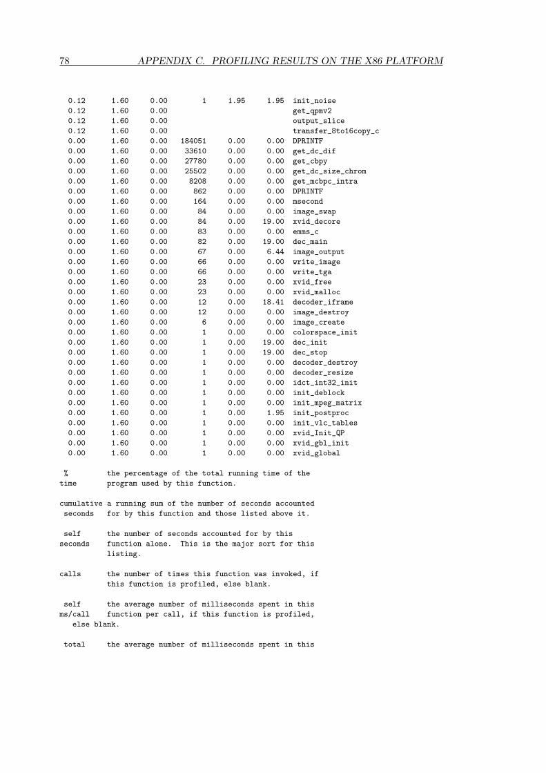
78 APPENDIX C. PROFILING RESULTS ON THE X86 PLATFORM
0.12 1.60 0.00 1 1.95 1.95 init_noise
0.12 1.60 0.00 get_qpmv2
0.12 1.60 0.00 output_slice
0.12 1.60 0.00 transfer_8to16copy_c
0.00 1.60 0.00 184051 0.00 0.00 DPRINTF
0.00 1.60 0.00 33610 0.00 0.00 get_dc_dif
0.00 1.60 0.00 27780 0.00 0.00 get_cbpy
0.00 1.60 0.00 25502 0.00 0.00 get_dc_size_chrom
0.00 1.60 0.00 8208 0.00 0.00 get_mcbpc_intra
0.00 1.60 0.00 862 0.00 0.00 DPRINTF
0.00 1.60 0.00 164 0.00 0.00 msecond
0.00 1.60 0.00 84 0.00 0.00 image_swap
0.00 1.60 0.00 84 0.00 19.00 xvid_decore
0.00 1.60 0.00 83 0.00 0.00 emms_c
0.00 1.60 0.00 82 0.00 19.00 dec_main
0.00 1.60 0.00 67 0.00 6.44 image_output
0.00 1.60 0.00 66 0.00 0.00 write_image
0.00 1.60 0.00 66 0.00 0.00 write_tga
0.00 1.60 0.00 23 0.00 0.00 xvid_free
0.00 1.60 0.00 23 0.00 0.00 xvid_malloc
0.00 1.60 0.00 12 0.00 18.41 decoder_iframe
0.00 1.60 0.00 12 0.00 0.00 image_destroy
0.00 1.60 0.00 6 0.00 0.00 image_create
0.00 1.60 0.00 1 0.00 0.00 colorspace_init
0.00 1.60 0.00 1 0.00 19.00 dec_init
0.00 1.60 0.00 1 0.00 19.00 dec_stop
0.00 1.60 0.00 1 0.00 0.00 decoder_destroy
0.00 1.60 0.00 1 0.00 0.00 decoder_resize
0.00 1.60 0.00 1 0.00 0.00 idct_int32_init
0.00 1.60 0.00 1 0.00 0.00 init_deblock
0.00 1.60 0.00 1 0.00 0.00 init_mpeg_matrix
0.00 1.60 0.00 1 0.00 1.95 init_postproc
0.00 1.60 0.00 1 0.00 0.00 init_vlc_tables
0.00 1.60 0.00 1 0.00 0.00 xvid_Init_QP
0.00 1.60 0.00 1 0.00 0.00 xvid_gbl_init
0.00 1.60 0.00 1 0.00 0.00 xvid_global
% the percentage of the total running time of the
time program used by this function.
cumulative a running sum of the number of seconds accounted
seconds for by this function and those listed above it.
self the number of seconds accounted for by this
seconds function alone. This is the major sort for this
listing.
calls the number of times this function was invoked, if
this function is profiled, else blank.
self the average number of milliseconds spent in this
ms/call function per call, if this function is profiled,
else blank.
total the average number of milliseconds spent in this

79
ms/call function and its descendents per call, if this
function is profiled, else blank.
name the name of the function. This is the minor sort
for this listing. The index shows the location of
the function in the gprof listing. If the index is
in parenthesis it shows where it would appear in
the gprof listing if it were to be printed.
Call graph (explanation follows)
granularity: each sample hit covers 4 byte(s) for 0.12% of 1.60 seconds
index % time self children called name
<spontaneous>
[1] 99.6 0.00 1.60 main [1]
0.00 1.56 82/82 dec_main [4]
0.00 0.02 1/1 dec_init [29]
0.00 0.02 1/1 dec_stop [30]
0.00 0.00 67/67 type2str [40]
0.00 0.00 164/164 msecond [52]
0.00 0.00 66/66 write_image [55]
-----------------------------------------------
0.00 0.02 1/84 dec_init [29]
0.00 0.02 1/84 dec_stop [30]
0.00 1.56 82/84 dec_main [4]
[2] 99.5 0.00 1.60 84 xvid_decore [2]
0.01 1.58 82/82 decoder_decode [3]
0.00 0.00 1/1 decoder_create [35]
0.00 0.00 1/1 decoder_destroy [62]
-----------------------------------------------
0.01 1.58 82/82 xvid_decore [2]
[3] 99.3 0.01 1.58 82 decoder_decode [3]
0.01 0.48 30/30 decoder_pframe [5]
0.03 0.40 25/25 decoder_bframe [8]
0.00 0.43 67/67 image_output [9]
0.00 0.22 12/12 decoder_iframe [14]
0.00 0.00 80/80 BitstreamReadHeaders [39]
0.00 0.00 84/84 image_swap [53]
0.00 0.00 82/83 emms_c [54]
0.00 0.00 80/184051 DPRINTF [46]
0.00 0.00 1/1 decoder_resize [63]
-----------------------------------------------
0.00 1.56 82/82 main [1]
[4] 97.1 0.00 1.56 82 dec_main [4]
0.00 1.56 82/84 xvid_decore [2]
-----------------------------------------------
0.01 0.48 30/30 decoder_decode [3]
[5] 30.9 0.01 0.48 30 decoder_pframe [5]
0.01 0.32 15977/22662 decoder_mbinter [6]
0.00 0.12 4543/12751 decoder_mbintra [11]
0.01 0.00 20021/20021 get_pmv2 [32]
0.01 0.00 30/80 image_setedges [24]

80 APPENDIX C. PROFILING RESULTS ON THE X86 PLATFORM
0.00 0.00 40042/70532 get_mv [33]
0.00 0.00 19572/19572 get_mcbpc_inter [38]
0.00 0.00 20520/45828 check_resync_marker [37]
0.00 0.00 99257/184051 DPRINTF [46]
0.00 0.00 19572/27780 get_cbpy [48]
-----------------------------------------------
0.00 0.14 6685/22662 decoder_bframe [8]
0.01 0.32 15977/22662 decoder_pframe [5]
[6] 29.4 0.01 0.46 22662 decoder_mbinter [6]
0.01 0.34 16925/21721 decoder_mb_decode [7]
0.04 0.00 40660/55797 interpolate8x8_halfpel_hv_c [17]
0.04 0.00 56014/136681 transfer8x8_copy_c [16]
0.01 0.00 17837/32096 interpolate8x8_halfpel_h_c [27]
0.01 0.00 21461/36378 interpolate8x8_halfpel_v_c [28]
-----------------------------------------------
0.00 0.10 4796/21721 decoder_bf_interpolate_mbinter [13]
0.01 0.34 16925/21721 decoder_mbinter [6]
[7] 27.8 0.02 0.43 21721 decoder_mb_decode [7]
0.17 0.00 90615/167121 idct_int32 [12]
0.13 0.01 90615/90615 get_inter_block [15]
0.06 0.00 90615/90615 dequant_h263_inter_c [18]
0.06 0.00 90615/90615 transfer_16to8add_c [19]
-----------------------------------------------
0.03 0.40 25/25 decoder_decode [3]
[8] 27.0 0.03 0.40 25 decoder_bframe [8]
0.01 0.23 10415/10415 decoder_bf_interpolate_mbinter [13]
0.00 0.14 6685/22662 decoder_mbinter [6]
0.02 0.00 50/80 image_setedges [24]
0.00 0.00 30490/70532 get_mv [33]
0.00 0.00 17100/45828 check_resync_marker [37]
-----------------------------------------------
0.00 0.43 67/67 decoder_decode [3]
[9] 26.9 0.00 0.43 67 image_output [9]
0.43 0.00 67/67 yv12_to_bgr_c [10]
-----------------------------------------------
0.43 0.00 67/67 image_output [9]
[10] 26.9 0.43 0.00 67 yv12_to_bgr_c [10]
-----------------------------------------------
0.00 0.12 4543/12751 decoder_pframe [5]
0.00 0.22 8208/12751 decoder_iframe [14]
[11] 21.4 0.01 0.34 12751 decoder_mbintra [11]
0.14 0.00 76506/167121 idct_int32 [12]
0.05 0.00 76506/76506 transfer_16to8copy_c [20]
0.04 0.00 32110/32110 get_intra_block [21]
0.04 0.00 76506/76506 dequant_h263_intra_c [22]
0.03 0.00 76506/76506 predict_acdc [25]
0.02 0.00 76506/76506 add_acdc [26]
0.00 0.00 51004/51004 get_dc_size_lum [34]
0.00 0.00 76506/184051 DPRINTF [46]
0.00 0.00 33610/33610 get_dc_dif [47]
0.00 0.00 25502/25502 get_dc_size_chrom [49]
-----------------------------------------------
0.14 0.00 76506/167121 decoder_mbintra [11]
0.17 0.00 90615/167121 decoder_mb_decode [7]
[12] 19.7 0.32 0.00 167121 idct_int32 [12]

81
-----------------------------------------------
0.01 0.23 10415/10415 decoder_bframe [8]
[13] 15.0 0.01 0.23 10415 decoder_bf_interpolate_mbinter [13]
0.00 0.10 4796/21721 decoder_mb_decode [7]
0.06 0.00 80667/136681 transfer8x8_copy_c [16]
0.03 0.00 62490/62490 interpolate8x8_avg2_c [23]
0.02 0.00 15137/55797 interpolate8x8_halfpel_hv_c [17]
0.01 0.00 14259/32096 interpolate8x8_halfpel_h_c [27]
0.01 0.00 14917/36378 interpolate8x8_halfpel_v_c [28]
-----------------------------------------------
0.00 0.22 12/12 decoder_decode [3]
[14] 13.8 0.00 0.22 12 decoder_iframe [14]
0.00 0.22 8208/12751 decoder_mbintra [11]
0.00 0.00 8208/45828 check_resync_marker [37]
0.00 0.00 8208/184051 DPRINTF [46]
0.00 0.00 8208/8208 get_mcbpc_intra [50]
0.00 0.00 8208/27780 get_cbpy [48]
-----------------------------------------------
0.13 0.01 90615/90615 decoder_mb_decode [7]
[15] 9.1 0.13 0.01 90615 get_inter_block [15]
0.01 0.00 1139150/1603803 DPRINTF [31]
-----------------------------------------------
0.04 0.00 56014/136681 decoder_mbinter [6]
0.06 0.00 80667/136681 decoder_bf_interpolate_mbinter [13]
[16] 6.5 0.10 0.00 136681 transfer8x8_copy_c [16]
-----------------------------------------------
0.02 0.00 15137/55797 decoder_bf_interpolate_mbinter [13]
0.04 0.00 40660/55797 decoder_mbinter [6]
[17] 3.8 0.06 0.00 55797 interpolate8x8_halfpel_hv_c [17]
-----------------------------------------------
0.06 0.00 90615/90615 decoder_mb_decode [7]
[18] 3.5 0.06 0.00 90615 dequant_h263_inter_c [18]
-----------------------------------------------
0.06 0.00 90615/90615 decoder_mb_decode [7]
[19] 3.5 0.06 0.00 90615 transfer_16to8add_c [19]
-----------------------------------------------
0.05 0.00 76506/76506 decoder_mbintra [11]
[20] 3.0 0.05 0.00 76506 transfer_16to8copy_c [20]
-----------------------------------------------
0.04 0.00 32110/32110 decoder_mbintra [11]
[21] 2.8 0.04 0.00 32110 get_intra_block [21]
0.00 0.00 464653/1603803 DPRINTF [31]
-----------------------------------------------
0.04 0.00 76506/76506 decoder_mbintra [11]
[22] 2.8 0.04 0.00 76506 dequant_h263_intra_c [22]
-----------------------------------------------
0.03 0.00 62490/62490 decoder_bf_interpolate_mbinter [13]
[23] 2.1 0.03 0.00 62490 interpolate8x8_avg2_c [23]
-----------------------------------------------
0.01 0.00 30/80 decoder_pframe [5]
0.02 0.00 50/80 decoder_bframe [8]
[24] 1.9 0.03 0.00 80 image_setedges [24]
-----------------------------------------------
0.03 0.00 76506/76506 decoder_mbintra [11]
[25] 1.7 0.03 0.00 76506 predict_acdc [25]

82 APPENDIX C. PROFILING RESULTS ON THE X86 PLATFORM
-----------------------------------------------
0.02 0.00 76506/76506 decoder_mbintra [11]
[26] 1.3 0.02 0.00 76506 add_acdc [26]
0.00 0.00 136608/136608 DPRINTF [36]
-----------------------------------------------
0.01 0.00 14259/32096 decoder_bf_interpolate_mbinter [13]
0.01 0.00 17837/32096 decoder_mbinter [6]
[27] 1.3 0.02 0.00 32096 interpolate8x8_halfpel_h_c [27]
-----------------------------------------------
0.01 0.00 14917/36378 decoder_bf_interpolate_mbinter [13]
0.01 0.00 21461/36378 decoder_mbinter [6]
[28] 1.2 0.02 0.00 36378 interpolate8x8_halfpel_v_c [28]
-----------------------------------------------
0.00 0.02 1/1 main [1]
[29] 1.2 0.00 0.02 1 dec_init [29]
0.00 0.02 1/84 xvid_decore [2]
0.00 0.00 1/1 xvid_global [70]
-----------------------------------------------
0.00 0.02 1/1 main [1]
[30] 1.2 0.00 0.02 1 dec_stop [30]
0.00 0.02 1/84 xvid_decore [2]
-----------------------------------------------
0.00 0.00 464653/1603803 get_intra_block [21]
0.01 0.00 1139150/1603803 get_inter_block [15]
[31] 1.0 0.02 0.00 1603803 DPRINTF [31]
-----------------------------------------------
0.01 0.00 20021/20021 decoder_pframe [5]
[32] 0.7 0.01 0.00 20021 get_pmv2 [32]
-----------------------------------------------
0.00 0.00 30490/70532 decoder_bframe [8]
0.00 0.00 40042/70532 decoder_pframe [5]
[33] 0.2 0.00 0.00 70532 get_mv [33]
-----------------------------------------------
0.00 0.00 51004/51004 decoder_mbintra [11]
[34] 0.2 0.00 0.00 51004 get_dc_size_lum [34]
-----------------------------------------------
0.00 0.00 1/1 xvid_decore [2]
[35] 0.2 0.00 0.00 1 decoder_create [35]
0.00 0.00 1/1 init_postproc [42]
0.00 0.00 2/23 xvid_malloc [58]
0.00 0.00 1/1 init_mpeg_matrix [66]
-----------------------------------------------
0.00 0.00 136608/136608 add_acdc [26]
[36] 0.1 0.00 0.00 136608 DPRINTF [36]
-----------------------------------------------
0.00 0.00 8208/45828 decoder_iframe [14]
0.00 0.00 17100/45828 decoder_bframe [8]
0.00 0.00 20520/45828 decoder_pframe [5]
[37] 0.1 0.00 0.00 45828 check_resync_marker [37]
-----------------------------------------------
0.00 0.00 19572/19572 decoder_pframe [5]
[38] 0.1 0.00 0.00 19572 get_mcbpc_inter [38]
-----------------------------------------------
0.00 0.00 80/80 decoder_decode [3]
[39] 0.1 0.00 0.00 80 BitstreamReadHeaders [39]

83
0.00 0.00 862/862 DPRINTF [51]
-----------------------------------------------
0.00 0.00 67/67 main [1]
[40] 0.1 0.00 0.00 67 type2str [40]
-----------------------------------------------
0.00 0.00 1/1 init_postproc [42]
[41] 0.1 0.00 0.00 1 init_noise [41]
0.00 0.00 1/83 emms_c [54]
-----------------------------------------------
0.00 0.00 1/1 decoder_create [35]
[42] 0.1 0.00 0.00 1 init_postproc [42]
0.00 0.00 1/1 init_noise [41]
0.00 0.00 1/1 init_deblock [65]
-----------------------------------------------
<spontaneous>
[43] 0.1 0.00 0.00 get_qpmv2 [43]
-----------------------------------------------
<spontaneous>
[44] 0.1 0.00 0.00 output_slice [44]
-----------------------------------------------
<spontaneous>
[45] 0.1 0.00 0.00 transfer_8to16copy_c [45]
-----------------------------------------------
0.00 0.00 80/184051 decoder_decode [3]
0.00 0.00 8208/184051 decoder_iframe [14]
0.00 0.00 76506/184051 decoder_mbintra [11]
0.00 0.00 99257/184051 decoder_pframe [5]
[46] 0.0 0.00 0.00 184051 DPRINTF [46]
-----------------------------------------------
0.00 0.00 33610/33610 decoder_mbintra [11]
[47] 0.0 0.00 0.00 33610 get_dc_dif [47]
-----------------------------------------------
0.00 0.00 8208/27780 decoder_iframe [14]
0.00 0.00 19572/27780 decoder_pframe [5]
[48] 0.0 0.00 0.00 27780 get_cbpy [48]
-----------------------------------------------
0.00 0.00 25502/25502 decoder_mbintra [11]
[49] 0.0 0.00 0.00 25502 get_dc_size_chrom [49]
-----------------------------------------------
0.00 0.00 8208/8208 decoder_iframe [14]
[50] 0.0 0.00 0.00 8208 get_mcbpc_intra [50]
-----------------------------------------------
0.00 0.00 862/862 BitstreamReadHeaders [39]
[51] 0.0 0.00 0.00 862 DPRINTF [51]
-----------------------------------------------
0.00 0.00 164/164 main [1]
[52] 0.0 0.00 0.00 164 msecond [52]
-----------------------------------------------
0.00 0.00 84/84 decoder_decode [3]
[53] 0.0 0.00 0.00 84 image_swap [53]
-----------------------------------------------
0.00 0.00 1/83 init_noise [41]
0.00 0.00 82/83 decoder_decode [3]
[54] 0.0 0.00 0.00 83 emms_c [54]
-----------------------------------------------

84 APPENDIX C. PROFILING RESULTS ON THE X86 PLATFORM
0.00 0.00 66/66 main [1]
[55] 0.0 0.00 0.00 66 write_image [55]
0.00 0.00 66/66 write_tga [56]
-----------------------------------------------
0.00 0.00 66/66 write_image [55]
[56] 0.0 0.00 0.00 66 write_tga [56]
-----------------------------------------------
0.00 0.00 5/23 decoder_destroy [62]
0.00 0.00 18/23 image_destroy [59]
[57] 0.0 0.00 0.00 23 xvid_free [57]
-----------------------------------------------
0.00 0.00 2/23 decoder_create [35]
0.00 0.00 3/23 decoder_resize [63]
0.00 0.00 18/23 image_create [60]
[58] 0.0 0.00 0.00 23 xvid_malloc [58]
-----------------------------------------------
0.00 0.00 6/12 decoder_resize [63]
0.00 0.00 6/12 decoder_destroy [62]
[59] 0.0 0.00 0.00 12 image_destroy [59]
0.00 0.00 18/23 xvid_free [57]
-----------------------------------------------
0.00 0.00 6/6 decoder_resize [63]
[60] 0.0 0.00 0.00 6 image_create [60]
0.00 0.00 18/23 xvid_malloc [58]
-----------------------------------------------
0.00 0.00 1/1 xvid_gbl_init [69]
[61] 0.0 0.00 0.00 1 colorspace_init [61]
-----------------------------------------------
0.00 0.00 1/1 xvid_decore [2]
[62] 0.0 0.00 0.00 1 decoder_destroy [62]
0.00 0.00 6/12 image_destroy [59]
0.00 0.00 5/23 xvid_free [57]
-----------------------------------------------
0.00 0.00 1/1 decoder_decode [3]
[63] 0.0 0.00 0.00 1 decoder_resize [63]
0.00 0.00 6/12 image_destroy [59]
0.00 0.00 6/6 image_create [60]
0.00 0.00 3/23 xvid_malloc [58]
-----------------------------------------------
0.00 0.00 1/1 xvid_gbl_init [69]
[64] 0.0 0.00 0.00 1 idct_int32_init [64]
-----------------------------------------------
0.00 0.00 1/1 init_postproc [42]
[65] 0.0 0.00 0.00 1 init_deblock [65]
-----------------------------------------------
0.00 0.00 1/1 decoder_create [35]
[66] 0.0 0.00 0.00 1 init_mpeg_matrix [66]
-----------------------------------------------
0.00 0.00 1/1 xvid_gbl_init [69]
[67] 0.0 0.00 0.00 1 init_vlc_tables [67]
-----------------------------------------------
0.00 0.00 1/1 xvid_gbl_init [69]
[68] 0.0 0.00 0.00 1 xvid_Init_QP [68]
-----------------------------------------------
0.00 0.00 1/1 xvid_global [70]

85
[69] 0.0 0.00 0.00 1 xvid_gbl_init [69]
0.00 0.00 1/1 idct_int32_init [64]
0.00 0.00 1/1 init_vlc_tables [67]
0.00 0.00 1/1 xvid_Init_QP [68]
0.00 0.00 1/1 colorspace_init [61]
-----------------------------------------------
0.00 0.00 1/1 dec_init [29]
[70] 0.0 0.00 0.00 1 xvid_global [70]
0.00 0.00 1/1 xvid_gbl_init [69]
-----------------------------------------------
This table describes the call tree of the program, and was sorted by
the total amount of time spent in each function and its children.
Each entry in this table consists of several lines. The line with the
index number at the left hand margin lists the current function.
The lines above it list the functions that called this function,
and the lines below it list the functions this one called.
This line lists:
index A unique number given to each element of the table.
Index numbers are sorted numerically.
The index number is printed next to every function name so
it is easier to look up where the function in the table.
% time This is the percentage of the ‘total’ time that was spent
in this function and its children. Note that due to
different viewpoints, functions excluded by options, etc,
these numbers will NOT add up to 100%.
self This is the total amount of time spent in this function.
children This is the total amount of time propagated into this
function by its children.
called This is the number of times the function was called.
If the function called itself recursively, the number
only includes non-recursive calls, and is followed by
a ‘+’ and the number of recursive calls.
name The name of the current function. The index number is
printed after it. If the function is a member of a
cycle, the cycle number is printed between the
function’s name and the index number.
For the function’s parents, the fields have the following meanings:
self This is the amount of time that was propagated directly
from the function into this parent.
children This is the amount of time that was propagated from
the function’s children into this parent.
called This is the number of times this parent called the
function ‘/’ the total number of times the function

86 APPENDIX C. PROFILING RESULTS ON THE X86 PLATFORM
was called. Recursive calls to the function are not
included in the number after the ‘/’.
name This is the name of the parent. The parent’s index
number is printed after it. If the parent is a
member of a cycle, the cycle number is printed between
the name and the index number.
If the parents of the function cannot be determined, the word
‘<spontaneous>’ is printed in the ‘name’ field, and all the other
fields are blank.
For the function’s children, the fields have the following meanings:
self This is the amount of time that was propagated directly
from the child into the function.
children This is the amount of time that was propagated from the
child’s children to the function.
called This is the number of times the function called
this child ‘/’ the total number of times the child
was called. Recursive calls by the child are not
listed in the number after the ‘/’.
name This is the name of the child. The child’s index
number is printed after it. If the child is a
member of a cycle, the cycle number is printed
between the name and the index number.
If there are any cycles (circles) in the call graph, there is an
entry for the cycle-as-a-whole. This entry shows who called the
cycle (as parents) and the members of the cycle (as children.)
The ‘+’ recursive calls entry shows the number of function calls that
were internal to the cycle, and the calls entry for each member shows,
for that member, how many times it was called from other members of
the cycle.
Index by function name
[39] BitstreamReadHeaders [22] dequant_h263_intra_c [42] init_postproc
[31] DPRINTF (xvid_decraw.c) [54] emms_c [67] init_vlc_tables
[46] DPRINTF (xvid_decraw.c) [48] get_cbpy [23] interpolate8x8_avg2_c
[51] DPRINTF (xvid_decraw.c) [47] get_dc_dif [27] interpolate8x8_halfpel_h_c
[36] DPRINTF (xvid_decraw.c) [49] get_dc_size_chrom [17] interpolate8x8_halfpel_hv_c
[26] add_acdc [34] get_dc_size_lum [28] interpolate8x8_halfpel_v_c
[37] check_resync_marker [15] get_inter_block [52] msecond (xvid_decraw.c)
[61] colorspace_init [21] get_intra_block [44] output_slice
[29] dec_init (xvid_decraw.c) [38] get_mcbpc_inter [25] predict_acdc
[4] dec_main (xvid_decraw.c) [50] get_mcbpc_intra [16] transfer8x8_copy_c
[30] dec_stop (xvid_decraw.c) [33] get_mv [19] transfer_16to8add_c
[13] decoder_bf_interpolate_mbinter (xvid_decraw.c) [32] get_pmv2 [20] transfer_16to8copy_c
[8] decoder_bframe (xvid_decraw.c) [43] get_qpmv2 [45] transfer_8to16copy_c

87
[35] decoder_create [12] idct_int32 [40] type2str
[3] decoder_decode [64] idct_int32_init [55] write_image (xvid_decraw.c)
[62] decoder_destroy [60] image_create [56] write_tga (xvid_decraw.c)
[14] decoder_iframe (xvid_decraw.c) [59] image_destroy [68] xvid_Init_QP
[7] decoder_mb_decode (xvid_decraw.c) [9] image_output [2] xvid_decore
[6] decoder_mbinter (xvid_decraw.c) [24] image_setedges [57] xvid_free
[11] decoder_mbintra (xvid_decraw.c) [53] image_swap [69] xvid_gbl_init (xvid_decraw.c)
[5] decoder_pframe (xvid_decraw.c) [65] init_deblock [70] xvid_global
[63] decoder_resize (xvid_decraw.c) [66] init_mpeg_matrix [58] xvid_malloc
[18] dequant_h263_inter_c [41] init_noise [10] yv12_to_bgr_c

88 APPENDIX C. PROFILING RESULTS ON THE X86 PLATFORM

IDCT datapath and controllingFSM DThis appendix contains the Quartus designs of the row/col unit, which is part of thehardware IDCT, the IDCT datapath and the FSM controlling the IDCT datapath. Itperforms the 1-dimensional IDCT on a row or column. Figure D.1 shows the designof the row/col unit. Figure D.2 shows the details of the part ”IDCT DEEL” which isvisible in figure D.1. For clarity the figures are shown on separate pages.
89

90 APPENDIX D. IDCT DATAPATH AND CONTROLLING FSM
Figure D.1: Quartus design of the row/col unit.

91
Figure D.2: Quartus design of ”IDCT DEEL” block which is part of the row/col unit.

92 APPENDIX D. IDCT DATAPATH AND CONTROLLING FSM
Figure D.3: Quartus design of the IDCT datapath.

93
Figure D.4: Simulation of all the signals originating from the FSM controlling the IDCTdatapath.

94 APPENDIX D. IDCT DATAPATH AND CONTROLLING FSM

Source code of XviD decoder:decoder.c EThis appendix contains part of the XviD source code containing the decoding functions.The file listed is decoder.c from the src directory. It is available under the GNUGeneral Public License, which is shown in appendix F./*****************************************************************************
*
* XVID MPEG-4 VIDEO CODEC
* - Decoder Module -
*
* Copyright(C) 2002 MinChen <[email protected]>
* 2002-2003 Peter Ross <[email protected]>
*
* This program is free software ; you can redistribute it and/or modify
* it under the terms of the GNU General Public License as published by
* the Free Software Foundation ; either version 2 of the License, or
* (at your option) any later version.
*
* This program is distributed in the hope that it will be useful,
* but WITHOUT ANY WARRANTY ; without even the implied warranty of
* MERCHANTABILITY or FITNESS FOR A PARTICULAR PURPOSE. See the
* GNU General Public License for more details.
*
* You should have received a copy of the GNU General Public License
* along with this program ; if not, write to the Free Software
* Foundation, Inc., 59 Temple Place, Suite 330, Boston, MA 02111-1307 USA
*
* $Id$
*
****************************************************************************/
#include <stdio.h>
#include <stdlib.h>
#include <string.h>
#ifdef BFRAMES_DEC_DEBUG
#define BFRAMES_DEC
#endif
#include "xvid.h"
#include "portab.h"
#include "global.h"
#include "decoder.h"
#include "bitstream/bitstream.h"
#include "bitstream/mbcoding.h"
#include "quant/quant.h"
#include "quant/quant_matrix.h"
#include "dct/idct.h"
#include "dct/fdct.h"
#include "utils/mem_transfer.h"
#include "image/interpolate8x8.h"
#include "image/reduced.h"
#include "image/font.h"
#include "bitstream/mbcoding.h"
#include "prediction/mbprediction.h"
#include "utils/timer.h"
#include "utils/emms.h"
#include "motion/motion.h"
#include "motion/gmc.h"
#include "image/image.h"
#include "image/colorspace.h"
#include "image/postprocessing.h"
#include "utils/mem_align.h"
static int
decoder_resize(DECODER * dec)
{
/* free existing */
image_destroy(&dec->cur, dec->edged_width, dec->edged_height);
image_destroy(&dec->refn[0], dec->edged_width, dec->edged_height);
95

96 APPENDIX E. SOURCE CODE OF XVID DECODER: DECODER.C
image_destroy(&dec->refn[1], dec->edged_width, dec->edged_height);
image_destroy(&dec->tmp, dec->edged_width, dec->edged_height);
image_destroy(&dec->qtmp, dec->edged_width, dec->edged_height);
image_destroy(&dec->gmc, dec->edged_width, dec->edged_height);
if (dec->last_mbs)
xvid_free(dec->last_mbs);
if (dec->mbs)
xvid_free(dec->mbs);
if (dec->qscale)
xvid_free(dec->qscale);
/* realloc */
dec->mb_width = (dec->width + 15) / 16;
dec->mb_height = (dec->height + 15) / 16;
dec->edged_width = 16 * dec->mb_width + 2 * EDGE_SIZE;
dec->edged_height = 16 * dec->mb_height + 2 * EDGE_SIZE;
if (image_create(&dec->cur, dec->edged_width, dec->edged_height)) {
xvid_free(dec);
return XVID_ERR_MEMORY;
}
if (image_create(&dec->refn[0], dec->edged_width, dec->edged_height)) {
image_destroy(&dec->cur, dec->edged_width, dec->edged_height);
xvid_free(dec);
return XVID_ERR_MEMORY;
}
/* Support B-frame to reference last 2 frame */
if (image_create(&dec->refn[1], dec->edged_width, dec->edged_height)) {
image_destroy(&dec->cur, dec->edged_width, dec->edged_height);
image_destroy(&dec->refn[0], dec->edged_width, dec->edged_height);
xvid_free(dec);
return XVID_ERR_MEMORY;
}
if (image_create(&dec->tmp, dec->edged_width, dec->edged_height)) {
image_destroy(&dec->cur, dec->edged_width, dec->edged_height);
image_destroy(&dec->refn[0], dec->edged_width, dec->edged_height);
image_destroy(&dec->refn[1], dec->edged_width, dec->edged_height);
xvid_free(dec);
return XVID_ERR_MEMORY;
}
if (image_create(&dec->qtmp, dec->edged_width, dec->edged_height)) {
image_destroy(&dec->cur, dec->edged_width, dec->edged_height);
image_destroy(&dec->refn[0], dec->edged_width, dec->edged_height);
image_destroy(&dec->refn[1], dec->edged_width, dec->edged_height);
image_destroy(&dec->tmp, dec->edged_width, dec->edged_height);
xvid_free(dec);
return XVID_ERR_MEMORY;
}
if (image_create(&dec->gmc, dec->edged_width, dec->edged_height)) {
image_destroy(&dec->qtmp, dec->edged_width, dec->edged_height);
image_destroy(&dec->cur, dec->edged_width, dec->edged_height);
image_destroy(&dec->refn[0], dec->edged_width, dec->edged_height);
image_destroy(&dec->refn[1], dec->edged_width, dec->edged_height);
image_destroy(&dec->tmp, dec->edged_width, dec->edged_height);
xvid_free(dec);
return XVID_ERR_MEMORY;
}
dec->mbs =
xvid_malloc(sizeof(MACROBLOCK) * dec->mb_width * dec->mb_height,
CACHE_LINE);
if (dec->mbs == NULL) {
image_destroy(&dec->cur, dec->edged_width, dec->edged_height);
image_destroy(&dec->refn[0], dec->edged_width, dec->edged_height);
image_destroy(&dec->refn[1], dec->edged_width, dec->edged_height);
image_destroy(&dec->tmp, dec->edged_width, dec->edged_height);
image_destroy(&dec->qtmp, dec->edged_width, dec->edged_height);
xvid_free(dec);
return XVID_ERR_MEMORY;
}
memset(dec->mbs, 0, sizeof(MACROBLOCK) * dec->mb_width * dec->mb_height);
/* For skip MB flag */
dec->last_mbs =
xvid_malloc(sizeof(MACROBLOCK) * dec->mb_width * dec->mb_height,
CACHE_LINE);
if (dec->last_mbs == NULL) {
xvid_free(dec->mbs);
image_destroy(&dec->cur, dec->edged_width, dec->edged_height);
image_destroy(&dec->refn[0], dec->edged_width, dec->edged_height);

97
image_destroy(&dec->refn[1], dec->edged_width, dec->edged_height);
image_destroy(&dec->tmp, dec->edged_width, dec->edged_height);
image_destroy(&dec->qtmp, dec->edged_width, dec->edged_height);
xvid_free(dec);
return XVID_ERR_MEMORY;
}
memset(dec->last_mbs, 0, sizeof(MACROBLOCK) * dec->mb_width * dec->mb_height);
/* nothing happens if that fails */
dec->qscale =
xvid_malloc(sizeof(int) * dec->mb_width * dec->mb_height, CACHE_LINE);
if (dec->qscale)
memset(dec->qscale, 0, sizeof(int) * dec->mb_width * dec->mb_height);
return 0;
}
int
decoder_create(xvid_dec_create_t * create)
{
DECODER *dec;
DAMP_DEBUG(printf("decoder_create\r\n");)
if (XVID_VERSION_MAJOR(create->version) != 1) /* v1.x.x */
return XVID_ERR_VERSION;
DAMP_DEBUG(printf("decoder_create: malloc\r\n");)
dec = xvid_malloc(sizeof(DECODER), CACHE_LINE);
if (dec == NULL) {
return XVID_ERR_MEMORY;
}
DAMP_DEBUG(printf("decoder_create: memset\r\n");)
memset(dec, 0, sizeof(DECODER));
DAMP_DEBUG(printf("decoder_create: xvid_malloc\r\n");)
dec->mpeg_quant_matrices = xvid_malloc(sizeof(uint16_t) * 64 * 8, CACHE_LINE);
if (dec->mpeg_quant_matrices == NULL) {
xvid_free(dec);
return XVID_ERR_MEMORY;
}
DAMP_DEBUG(printf("decoder_create: handle\r\n");)
create->handle = dec;
dec->width = create->width;
dec->height = create->height;
image_null(&dec->cur);
image_null(&dec->refn[0]);
image_null(&dec->refn[1]);
image_null(&dec->tmp);
image_null(&dec->qtmp);
/* image based GMC */
image_null(&dec->gmc);
DAMP_DEBUG(printf("decoder_create: mbs\r\n");)
dec->mbs = NULL;
dec->last_mbs = NULL;
dec->qscale = NULL;
DAMP_DEBUG(printf("decoder_create: init_timer\r\n");)
init_timer();
DAMP_DEBUG(printf("decoder_create: postproc\r\n");)
init_postproc(&dec->postproc);
DAMP_DEBUG(printf("decoder_create: init_mpeg_matrix\r\n");)
init_mpeg_matrix(dec->mpeg_quant_matrices);
DAMP_DEBUG(printf("decoder_create: bframe\r\n");)
/* For B-frame support (used to save reference frame’s time */
dec->frames = 0;
dec->time = dec->time_base = dec->last_time_base = 0;
dec->low_delay = 0;
dec->packed_mode = 0;
dec->time_inc_resolution = 1; /* until VOL header says otherwise */
DAMP_DEBUG(printf("decoder_create: dim\r\n");)
dec->fixed_dimensions = (dec->width > 0 && dec->height > 0);
DAMP_DEBUG(printf("decoder_create: return\r\n");)
if (dec->fixed_dimensions)

98 APPENDIX E. SOURCE CODE OF XVID DECODER: DECODER.C
return decoder_resize(dec);
else
return 0;
}
int
decoder_destroy(DECODER * dec)
{
xvid_free(dec->last_mbs);
xvid_free(dec->mbs);
xvid_free(dec->qscale);
/* image based GMC */
image_destroy(&dec->gmc, dec->edged_width, dec->edged_height);
image_destroy(&dec->refn[0], dec->edged_width, dec->edged_height);
image_destroy(&dec->refn[1], dec->edged_width, dec->edged_height);
image_destroy(&dec->tmp, dec->edged_width, dec->edged_height);
image_destroy(&dec->qtmp, dec->edged_width, dec->edged_height);
image_destroy(&dec->cur, dec->edged_width, dec->edged_height);
xvid_free(dec->mpeg_quant_matrices);
xvid_free(dec);
write_timer();
return 0;
}
static const int32_t dquant_table[4] = {
-1, -2, 1, 2
};
/* decode an intra macroblock */
static void
decoder_mbintra(DECODER * dec,
MACROBLOCK * pMB,
const uint32_t x_pos,
const uint32_t y_pos,
const uint32_t acpred_flag,
const uint32_t cbp,
Bitstream * bs,
const uint32_t quant,
const uint32_t intra_dc_threshold,
const unsigned int bound,
const int reduced_resolution)
{
DECLARE_ALIGNED_MATRIX(block, 6, 64, int16_t, CACHE_LINE);
DECLARE_ALIGNED_MATRIX(data, 6, 64, int16_t, CACHE_LINE);
uint32_t stride = dec->edged_width;
uint32_t stride2 = stride / 2;
uint32_t next_block = stride * 8;
uint32_t i;
uint32_t iQuant = pMB->quant;
uint8_t *pY_Cur, *pU_Cur, *pV_Cur;
if (reduced_resolution) {
pY_Cur = dec->cur.y + (y_pos << 5) * stride + (x_pos << 5);
pU_Cur = dec->cur.u + (y_pos << 4) * stride2 + (x_pos << 4);
pV_Cur = dec->cur.v + (y_pos << 4) * stride2 + (x_pos << 4);
}else{
pY_Cur = dec->cur.y + (y_pos << 4) * stride + (x_pos << 4);
pU_Cur = dec->cur.u + (y_pos << 3) * stride2 + (x_pos << 3);
pV_Cur = dec->cur.v + (y_pos << 3) * stride2 + (x_pos << 3);
}
memset(block, 0, 6 * 64 * sizeof(int16_t)); /* clear */
for (i = 0; i < 6; i++) {
uint32_t iDcScaler = get_dc_scaler(iQuant, i < 4);
int16_t predictors[8];
int start_coeff;
start_timer();
predict_acdc(dec->mbs, x_pos, y_pos, dec->mb_width, i, &block[i * 64],
iQuant, iDcScaler, predictors, bound);
if (!acpred_flag) {
pMB->acpred_directions[i] = 0;
}
stop_prediction_timer();
if (quant < intra_dc_threshold) {
int dc_size;
int dc_dif;
dc_size = i < 4 ? get_dc_size_lum(bs) : get_dc_size_chrom(bs);

99
dc_dif = dc_size ? get_dc_dif(bs, dc_size) : 0;
if (dc_size > 8) {
BitstreamSkip(bs, 1); /* marker */
}
block[i * 64 + 0] = dc_dif;
start_coeff = 1;
DPRINTF(XVID_DEBUG_COEFF,"block[0] %i\n", dc_dif);
} else {
start_coeff = 0;
}
start_timer();
if (cbp & (1 << (5 - i))) /* coded */
{
int direction = dec->alternate_vertical_scan ?
2 : pMB->acpred_directions[i];
get_intra_block(bs, &block[i * 64], direction, start_coeff);
}
stop_coding_timer();
start_timer();
add_acdc(pMB, i, &block[i * 64], iDcScaler, predictors, dec->bs_version);
stop_prediction_timer();
start_timer();
if (dec->quant_type == 0) {
dequant_h263_intra(&data[i * 64], &block[i * 64], iQuant, iDcScaler, dec->mpeg_quant_matrices);
} else {
dequant_mpeg_intra(&data[i * 64], &block[i * 64], iQuant, iDcScaler, dec->mpeg_quant_matrices);
}
stop_iquant_timer();
start_timer();
//DAMP
if (USE_HARDWARE) {
#if defined(STANDALONE)
//us_hardware_idct(data,data);
us_hardware_idct(&data[i * 64],&data[i * 64]);
#elif defined(LINUX_USER)
us_hardware_idct_ioctl(&data[i * 64]);
#else
idct(&data[i * 64]);
#endif
} else {
idct(&data[i * 64]);
}
//DAMP idct(&data[i * 64]);
stop_idct_timer();
}
if (dec->interlacing && pMB->field_dct) {
next_block = stride;
stride *= 2;
}
start_timer();
if (reduced_resolution)
{
next_block*=2;
copy_upsampled_8x8_16to8(pY_Cur, &data[0 * 64], stride);
copy_upsampled_8x8_16to8(pY_Cur + 16, &data[1 * 64], stride);
copy_upsampled_8x8_16to8(pY_Cur + next_block, &data[2 * 64], stride);
copy_upsampled_8x8_16to8(pY_Cur + 16 + next_block, &data[3 * 64], stride);
copy_upsampled_8x8_16to8(pU_Cur, &data[4 * 64], stride2);
copy_upsampled_8x8_16to8(pV_Cur, &data[5 * 64], stride2);
}else{
transfer_16to8copy(pY_Cur, &data[0 * 64], stride);
transfer_16to8copy(pY_Cur + 8, &data[1 * 64], stride);
transfer_16to8copy(pY_Cur + next_block, &data[2 * 64], stride);
transfer_16to8copy(pY_Cur + 8 + next_block, &data[3 * 64], stride);
transfer_16to8copy(pU_Cur, &data[4 * 64], stride2);
transfer_16to8copy(pV_Cur, &data[5 * 64], stride2);
}
stop_transfer_timer();
}
/*DAMP DAMP DAMP DAMP */
#define EX_GPIO (*(volatile unsigned long int *)(EX_REG_BASE))
#include "dct/hardware_idct_user.h"
#include "dct/hardware_idct_user_ioctl.h"

100 APPENDIX E. SOURCE CODE OF XVID DECODER: DECODER.C
static void
put_into_damp(Bitstream * bs, int direction, const quant_interFuncPtr dequant,
int16_t * data, const uint32_t quant, const uint16_t * mpeg_quant_matrices)
{
short array[64];
int timeout=350000;
int number_of_times = 10000;
DECLARE_ALIGNED_MATRIX(block, 1, 64, int16_t, CACHE_LINE);
memset(block, 0, 64 * sizeof(int16_t)); /* clear */
start_timer();
get_inter_block(bs, block, direction);
stop_coding_timer();
start_timer();
dequant(data, block, quant, mpeg_quant_matrices);
stop_iquant_timer();
start_timer();
#if 0
/* { static FILE *array_out;
static int file_counter;
int i;
*/ /* write number_of_times IDCT results to file */
/* if (file_counter == 0)
{ if ((array_out = fopen("array.h", "w")) == 0)
{
printf("Error opening output file (fatal)");
file_counter = number_of_times + 1;
}
else
{
fprintf(array_out, "unsigned long array[32*%i+1] = {", number_of_times); *//* 1 extra for last 0 value */
/* }
}
if (file_counter<number_of_times)
{
for (i=0;i<32;i++) fprintf(array_out, "0x%.8lx, ",((unsigned long*)data)[i]);
file_counter++;
}
if (file_counter == number_of_times)
*/{
// fprintf(array_out, "0 }\n *//*end of array with %i times 64 input values (2 values per 32 bit word) for IDCT*/", number_of_times);
/* fclose(array_out);
file_counter++;
}
}
*/
#endif 0
if (USE_HARDWARE) {
#if defined(STANDALONE)
//us_hardware_idct(data,data);
us_hardware_idct(data,data);
#elif defined(LINUX_USER)
us_hardware_idct_ioctl(data);
#else
idct(data);
#endif
#if 0
/*hardware part*/
/* unsigned long temp;
int i;
timeout=350000;
//memcpy(DPRAM, data, 128); /*copy 128 bytes to DPRAM*/
/* for (i=0;i<32;i++) DPRAM[i]=((unsigned long*)data)[i];
EX_GPIO = 0x01; /* reset IDCT */
/* temp = EX_GPIO;
while (temp & 0x00010000) temp = EX_GPIO;
//while (EX_GPIO & 0x00010000) /*wait to be sure circuit has been reset.*/
// {};
/* EX_GPIO = 0x00; /*start the IDCT by releasing reset*/
/* temp = EX_GPIO;
while ( !(temp & 0x00010000)) temp = EX_GPIO;
for(i=0;i<350000;i++)
// { /*wait until done signal received*/
/* temp = EX_GPIO;
if (!temp) temp = EX_GPIO;
// if(!(temp & 0x00010000)) break;
// timeout--;
// }
//memcpy(data, DPRAM, 128); /*copy 128 bytes back from DPRAM*/
/* for (i=0;i<32;i++) ((unsigned long*)array)[i]=DPRAM[i];

101
idct(data);
timeout = 0;
for (i=0;i<64;i++) if (array[i] != data[i]) timeout++;
if (timeout) printf("FOUT ");
EX_GPIO = 0x01; /* reset IDCT */
/* End of hardware part -> idct(data);*/
#endif 0
} else {
idct(data);
}
stop_idct_timer();
}
static void
decoder_mb_decode(DECODER * dec,
const uint32_t cbp,
Bitstream * bs,
uint8_t * pY_Cur,
uint8_t * pU_Cur,
uint8_t * pV_Cur,
const int reduced_resolution,
const MACROBLOCK * pMB)
{
/*DECLARE_ALIGNED_MATRIX(block, 1, 64, int16_t, CACHE_LINE);*/
DECLARE_ALIGNED_MATRIX(data, 6, 64, int16_t, CACHE_LINE);
int stride = dec->edged_width;
int next_block = stride * (reduced_resolution ? 16 : 8);
const int stride2 = stride/2;
int i;
const uint32_t iQuant = pMB->quant;
const int direction = dec->alternate_vertical_scan ? 2 : 0;
const quant_interFuncPtr dequant = dec->quant_type == 0 ? dequant_h263_inter : dequant_mpeg_inter;
/* PUT INTO DAMP */
for (i = 0; i < 6; i++) {
if (cbp & (1 << (5 - i))) { /* coded */
put_into_damp(bs, direction, dequant, &data[i * 64],
iQuant, dec->mpeg_quant_matrices);
/*memset(block, 0, 64 * sizeof(int16_t));*/ /* clear */
/*
start_timer();
get_inter_block(bs, block, direction);
stop_coding_timer();
start_timer();
dequant(&data[i * 64], block, iQuant, dec->mpeg_quant_matrices);
stop_iquant_timer();
start_timer();
idct(&data[i * 64]);
stop_idct_timer(); */
}
}
/* END OF DAMP */
if (dec->interlacing && pMB->field_dct) {
next_block = stride;
stride *= 2;
}
start_timer();
if (reduced_resolution) {
if (cbp & 32)
add_upsampled_8x8_16to8(pY_Cur, &data[0 * 64], stride);
if (cbp & 16)
add_upsampled_8x8_16to8(pY_Cur + 16, &data[1 * 64], stride);
if (cbp & 8)
add_upsampled_8x8_16to8(pY_Cur + next_block, &data[2 * 64], stride);
if (cbp & 4)
add_upsampled_8x8_16to8(pY_Cur + 16 + next_block, &data[3 * 64], stride);
if (cbp & 2)
add_upsampled_8x8_16to8(pU_Cur, &data[4 * 64], stride2);
if (cbp & 1)
add_upsampled_8x8_16to8(pV_Cur, &data[5 * 64], stride2);
} else {
if (cbp & 32)
transfer_16to8add(pY_Cur, &data[0 * 64], stride);
if (cbp & 16)
transfer_16to8add(pY_Cur + 8, &data[1 * 64], stride);

102 APPENDIX E. SOURCE CODE OF XVID DECODER: DECODER.C
if (cbp & 8)
transfer_16to8add(pY_Cur + next_block, &data[2 * 64], stride);
if (cbp & 4)
transfer_16to8add(pY_Cur + 8 + next_block, &data[3 * 64], stride);
if (cbp & 2)
transfer_16to8add(pU_Cur, &data[4 * 64], stride2);
if (cbp & 1)
transfer_16to8add(pV_Cur, &data[5 * 64], stride2);
}
stop_transfer_timer();
}
/* decode an inter macroblock */
static void
decoder_mbinter(DECODER * dec,
const MACROBLOCK * pMB,
const uint32_t x_pos,
const uint32_t y_pos,
const uint32_t cbp,
Bitstream * bs,
const uint32_t rounding,
const int reduced_resolution,
const int ref)
{
uint32_t stride = dec->edged_width;
uint32_t stride2 = stride / 2;
uint32_t i;
uint8_t *pY_Cur, *pU_Cur, *pV_Cur;
int uv_dx, uv_dy;
VECTOR mv[4]; /* local copy of mvs */
if (reduced_resolution) {
pY_Cur = dec->cur.y + (y_pos << 5) * stride + (x_pos << 5);
pU_Cur = dec->cur.u + (y_pos << 4) * stride2 + (x_pos << 4);
pV_Cur = dec->cur.v + (y_pos << 4) * stride2 + (x_pos << 4);
for (i = 0; i < 4; i++) {
mv[i].x = RRV_MV_SCALEUP(pMB->mvs[i].x);
mv[i].y = RRV_MV_SCALEUP(pMB->mvs[i].y);
}
} else {
pY_Cur = dec->cur.y + (y_pos << 4) * stride + (x_pos << 4);
pU_Cur = dec->cur.u + (y_pos << 3) * stride2 + (x_pos << 3);
pV_Cur = dec->cur.v + (y_pos << 3) * stride2 + (x_pos << 3);
for (i = 0; i < 4; i++)
mv[i] = pMB->mvs[i];
}
for (i = 0; i < 4; i++) {
/* clip to valid range */
int border = (int)(dec->mb_width - x_pos) << (5 + dec->quarterpel);
if (mv[i].x > border) {
DPRINTF(XVID_DEBUG_MV, "mv.x > max -- %d > %d, MB %d, %d", mv[i].x, border, x_pos, y_pos);
mv[i].x = border;
} else {
border = (-(int)x_pos-1) << (5 + dec->quarterpel);
if (mv[i].x < border) {
DPRINTF(XVID_DEBUG_MV, "mv.x < min -- %d < %d, MB %d, %d", mv[i].x, border, x_pos, y_pos);
mv[i].x = border;
}
}
border = (int)(dec->mb_height - y_pos) << (5 + dec->quarterpel);
if (mv[i].y > border) {
DPRINTF(XVID_DEBUG_MV, "mv.y > max -- %d > %d, MB %d, %d", mv[i].y, border, x_pos, y_pos);
mv[i].y = border;
} else {
border = (-(int)y_pos-1) << (5 + dec->quarterpel);
if (mv[i].y < border) {
DPRINTF(XVID_DEBUG_MV, "mv.y < min -- %d < %d, MB %d, %d", mv[i].y, border, x_pos, y_pos);
mv[i].y = border;
}
}
}
start_timer();
if (pMB->mode != MODE_INTER4V) { /* INTER, INTER_Q, NOT_CODED, FORWARD, BACKWARD */
uv_dx = mv[0].x;
uv_dy = mv[0].y;
if (dec->quarterpel) {
uv_dx /= 2;
uv_dy /= 2;
}
uv_dx = (uv_dx >> 1) + roundtab_79[uv_dx & 0x3];

103
uv_dy = (uv_dy >> 1) + roundtab_79[uv_dy & 0x3];
if (reduced_resolution)
interpolate32x32_switch(dec->cur.y, dec->refn[0].y, 32*x_pos, 32*y_pos,
mv[0].x, mv[0].y, stride, rounding);
else if (dec->quarterpel)
interpolate16x16_quarterpel(dec->cur.y, dec->refn[ref].y, dec->qtmp.y, dec->qtmp.y + 64,
dec->qtmp.y + 128, 16*x_pos, 16*y_pos,
mv[0].x, mv[0].y, stride, rounding);
else
interpolate16x16_switch(dec->cur.y, dec->refn[ref].y, 16*x_pos, 16*y_pos,
mv[0].x, mv[0].y, stride, rounding);
} else { /* MODE_INTER4V */
if(dec->quarterpel) {
uv_dx = (mv[0].x / 2) + (mv[1].x / 2) + (mv[2].x / 2) + (mv[3].x / 2);
uv_dy = (mv[0].y / 2) + (mv[1].y / 2) + (mv[2].y / 2) + (mv[3].y / 2);
} else {
uv_dx = mv[0].x + mv[1].x + mv[2].x + mv[3].x;
uv_dy = mv[0].y + mv[1].y + mv[2].y + mv[3].y;
}
uv_dx = (uv_dx >> 3) + roundtab_76[uv_dx & 0xf];
uv_dy = (uv_dy >> 3) + roundtab_76[uv_dy & 0xf];
if (reduced_resolution) {
interpolate16x16_switch(dec->cur.y, dec->refn[0].y, 32*x_pos, 32*y_pos,
mv[0].x, mv[0].y, stride, rounding);
interpolate16x16_switch(dec->cur.y, dec->refn[0].y , 32*x_pos + 16, 32*y_pos,
mv[1].x, mv[1].y, stride, rounding);
interpolate16x16_switch(dec->cur.y, dec->refn[0].y , 32*x_pos, 32*y_pos + 16,
mv[2].x, mv[2].y, stride, rounding);
interpolate16x16_switch(dec->cur.y, dec->refn[0].y , 32*x_pos + 16, 32*y_pos + 16,
mv[3].x, mv[3].y, stride, rounding);
interpolate16x16_switch(dec->cur.u, dec->refn[0].u , 16 * x_pos, 16 * y_pos,
uv_dx, uv_dy, stride2, rounding);
interpolate16x16_switch(dec->cur.v, dec->refn[0].v , 16 * x_pos, 16 * y_pos,
uv_dx, uv_dy, stride2, rounding);
} else if (dec->quarterpel) {
interpolate8x8_quarterpel(dec->cur.y, dec->refn[0].y , dec->qtmp.y, dec->qtmp.y + 64,
dec->qtmp.y + 128, 16*x_pos, 16*y_pos,
mv[0].x, mv[0].y, stride, rounding);
interpolate8x8_quarterpel(dec->cur.y, dec->refn[0].y , dec->qtmp.y, dec->qtmp.y + 64,
dec->qtmp.y + 128, 16*x_pos + 8, 16*y_pos,
mv[1].x, mv[1].y, stride, rounding);
interpolate8x8_quarterpel(dec->cur.y, dec->refn[0].y , dec->qtmp.y, dec->qtmp.y + 64,
dec->qtmp.y + 128, 16*x_pos, 16*y_pos + 8,
mv[2].x, mv[2].y, stride, rounding);
interpolate8x8_quarterpel(dec->cur.y, dec->refn[0].y , dec->qtmp.y, dec->qtmp.y + 64,
dec->qtmp.y + 128, 16*x_pos + 8, 16*y_pos + 8,
mv[3].x, mv[3].y, stride, rounding);
} else {
interpolate8x8_switch(dec->cur.y, dec->refn[0].y , 16*x_pos, 16*y_pos,
mv[0].x, mv[0].y, stride, rounding);
interpolate8x8_switch(dec->cur.y, dec->refn[0].y , 16*x_pos + 8, 16*y_pos,
mv[1].x, mv[1].y, stride, rounding);
interpolate8x8_switch(dec->cur.y, dec->refn[0].y , 16*x_pos, 16*y_pos + 8,
mv[2].x, mv[2].y, stride, rounding);
interpolate8x8_switch(dec->cur.y, dec->refn[0].y , 16*x_pos + 8, 16*y_pos + 8,
mv[3].x, mv[3].y, stride, rounding);
}
}
/* chroma */
if (reduced_resolution) {
interpolate16x16_switch(dec->cur.u, dec->refn[0].u, 16 * x_pos, 16 * y_pos,
uv_dx, uv_dy, stride2, rounding);
interpolate16x16_switch(dec->cur.v, dec->refn[0].v, 16 * x_pos, 16 * y_pos,
uv_dx, uv_dy, stride2, rounding);
} else {
interpolate8x8_switch(dec->cur.u, dec->refn[ref].u, 8 * x_pos, 8 * y_pos,
uv_dx, uv_dy, stride2, rounding);
interpolate8x8_switch(dec->cur.v, dec->refn[ref].v, 8 * x_pos, 8 * y_pos,
uv_dx, uv_dy, stride2, rounding);
}
stop_comp_timer();
if (cbp)
decoder_mb_decode(dec, cbp, bs, pY_Cur, pU_Cur, pV_Cur,
reduced_resolution, pMB);
}
static void
decoder_mbgmc(DECODER * dec,

104 APPENDIX E. SOURCE CODE OF XVID DECODER: DECODER.C
MACROBLOCK * const pMB,
const uint32_t x_pos,
const uint32_t y_pos,
const uint32_t fcode,
const uint32_t cbp,
Bitstream * bs,
const uint32_t rounding)
{
const uint32_t stride = dec->edged_width;
const uint32_t stride2 = stride / 2;
uint8_t *const pY_Cur=dec->cur.y + (y_pos << 4) * stride + (x_pos << 4);
uint8_t *const pU_Cur=dec->cur.u + (y_pos << 3) * stride2 + (x_pos << 3);
uint8_t *const pV_Cur=dec->cur.v + (y_pos << 3) * stride2 + (x_pos << 3);
NEW_GMC_DATA * gmc_data = &dec->new_gmc_data;
pMB->mvs[0] = pMB->mvs[1] = pMB->mvs[2] = pMB->mvs[3] = pMB->amv;
start_timer();
/* this is where the calculations are done */
gmc_data->predict_16x16(gmc_data,
dec->cur.y + y_pos*16*stride + x_pos*16, dec->refn[0].y,
stride, stride, x_pos, y_pos, rounding);
gmc_data->predict_8x8(gmc_data,
dec->cur.u + y_pos*8*stride2 + x_pos*8, dec->refn[0].u,
dec->cur.v + y_pos*8*stride2 + x_pos*8, dec->refn[0].v,
stride2, stride2, x_pos, y_pos, rounding);
gmc_data->get_average_mv(gmc_data, &pMB->amv, x_pos, y_pos, dec->quarterpel);
pMB->amv.x = gmc_sanitize(pMB->amv.x, dec->quarterpel, fcode);
pMB->amv.y = gmc_sanitize(pMB->amv.y, dec->quarterpel, fcode);
pMB->mvs[0] = pMB->mvs[1] = pMB->mvs[2] = pMB->mvs[3] = pMB->amv;
stop_transfer_timer();
if (cbp)
decoder_mb_decode(dec, cbp, bs, pY_Cur, pU_Cur, pV_Cur, 0, pMB);
}
static void
decoder_iframe(DECODER * dec,
Bitstream * bs,
int reduced_resolution,
int quant,
int intra_dc_threshold)
{
uint32_t bound;
uint32_t x, y;
uint32_t mb_width = dec->mb_width;
uint32_t mb_height = dec->mb_height;
if (reduced_resolution) {
mb_width = (dec->width + 31) / 32;
mb_height = (dec->height + 31) / 32;
}
bound = 0;
for (y = 0; y < mb_height; y++) {
for (x = 0; x < mb_width; x++) {
MACROBLOCK *mb;
uint32_t mcbpc;
uint32_t cbpc;
uint32_t acpred_flag;
uint32_t cbpy;
uint32_t cbp;
while (BitstreamShowBits(bs, 9) == 1)
BitstreamSkip(bs, 9);
if (check_resync_marker(bs, 0))
{
bound = read_video_packet_header(bs, dec, 0,
&quant, NULL, NULL, &intra_dc_threshold);
x = bound % mb_width;
y = bound / mb_width;
}
mb = &dec->mbs[y * dec->mb_width + x];

105
DPRINTF(XVID_DEBUG_MB, "macroblock (%i,%i) %08x\n", x, y, BitstreamShowBits(bs, 32));
mcbpc = get_mcbpc_intra(bs);
mb->mode = mcbpc & 7;
cbpc = (mcbpc >> 4);
acpred_flag = BitstreamGetBit(bs);
cbpy = get_cbpy(bs, 1);
cbp = (cbpy << 2) | cbpc;
if (mb->mode == MODE_INTRA_Q) {
quant += dquant_table[BitstreamGetBits(bs, 2)];
if (quant > 31) {
quant = 31;
} else if (quant < 1) {
quant = 1;
}
}
mb->quant = quant;
mb->mvs[0].x = mb->mvs[0].y =
mb->mvs[1].x = mb->mvs[1].y =
mb->mvs[2].x = mb->mvs[2].y =
mb->mvs[3].x = mb->mvs[3].y =0;
if (dec->interlacing) {
mb->field_dct = BitstreamGetBit(bs);
DPRINTF(XVID_DEBUG_MB,"deci: field_dct: %i\n", mb->field_dct);
}
decoder_mbintra(dec, mb, x, y, acpred_flag, cbp, bs, quant,
intra_dc_threshold, bound, reduced_resolution);
}
if(dec->out_frm)
output_slice(&dec->cur, dec->edged_width,dec->width,dec->out_frm,0,y,mb_width);
}
}
static void
get_motion_vector(DECODER * dec,
Bitstream * bs,
int x,
int y,
int k,
VECTOR * ret_mv,
int fcode,
const int bound)
{
const int scale_fac = 1 << (fcode - 1);
const int high = (32 * scale_fac) - 1;
const int low = ((-32) * scale_fac);
const int range = (64 * scale_fac);
const VECTOR pmv = get_pmv2(dec->mbs, dec->mb_width, bound, x, y, k);
VECTOR mv;
mv.x = get_mv(bs, fcode);
mv.y = get_mv(bs, fcode);
DPRINTF(XVID_DEBUG_MV,"mv_diff (%i,%i) pred (%i,%i) result (%i,%i)\n", mv.x, mv.y, pmv.x, pmv.y, mv.x+pmv.x, mv.y+pmv.y);
mv.x += pmv.x;
mv.y += pmv.y;
if (mv.x < low) {
mv.x += range;
} else if (mv.x > high) {
mv.x -= range;
}
if (mv.y < low) {
mv.y += range;
} else if (mv.y > high) {
mv.y -= range;
}
ret_mv->x = mv.x;
ret_mv->y = mv.y;
}
/* for P_VOP set gmc_warp to NULL */
static void
decoder_pframe(DECODER * dec,

106 APPENDIX E. SOURCE CODE OF XVID DECODER: DECODER.C
Bitstream * bs,
int rounding,
int reduced_resolution,
int quant,
int fcode,
int intra_dc_threshold,
const WARPPOINTS *const gmc_warp)
{
uint32_t x, y;
uint32_t bound;
int cp_mb, st_mb;
uint32_t mb_width = dec->mb_width;
uint32_t mb_height = dec->mb_height;
if (reduced_resolution) {
mb_width = (dec->width + 31) / 32;
mb_height = (dec->height + 31) / 32;
}
start_timer();
image_setedges(&dec->refn[0], dec->edged_width, dec->edged_height,
dec->width, dec->height, dec->bs_version);
stop_edges_timer();
if (gmc_warp) {
/* accuracy: 0==1/2, 1=1/4, 2=1/8, 3=1/16 */
generate_GMCparameters( dec->sprite_warping_points,
dec->sprite_warping_accuracy, gmc_warp,
dec->width, dec->height, &dec->new_gmc_data);
/* image warping is done block-based in decoder_mbgmc(), now */
}
bound = 0;
for (y = 0; y < mb_height; y++) {
cp_mb = st_mb = 0;
for (x = 0; x < mb_width; x++) {
MACROBLOCK *mb;
/* skip stuffing */
while (BitstreamShowBits(bs, 10) == 1)
BitstreamSkip(bs, 10);
if (check_resync_marker(bs, fcode - 1)) {
bound = read_video_packet_header(bs, dec, fcode - 1,
&quant, &fcode, NULL, &intra_dc_threshold);
x = bound % mb_width;
y = bound / mb_width;
}
mb = &dec->mbs[y * dec->mb_width + x];
DPRINTF(XVID_DEBUG_MB, "macroblock (%i,%i) %08x\n", x, y, BitstreamShowBits(bs, 32));
if (!(BitstreamGetBit(bs))) { /* block _is_ coded */
uint32_t mcbpc, cbpc, cbpy, cbp;
uint32_t intra, acpred_flag = 0;
int mcsel = 0; /* mcsel: ’0’=local motion, ’1’=GMC */
cp_mb++;
mcbpc = get_mcbpc_inter(bs);
mb->mode = mcbpc & 7;
cbpc = (mcbpc >> 4);
DPRINTF(XVID_DEBUG_MB, "mode %i\n", mb->mode);
DPRINTF(XVID_DEBUG_MB, "cbpc %i\n", cbpc);
intra = (mb->mode == MODE_INTRA || mb->mode == MODE_INTRA_Q);
if (gmc_warp && (mb->mode == MODE_INTER || mb->mode == MODE_INTER_Q))
mcsel = BitstreamGetBit(bs);
else if (intra)
acpred_flag = BitstreamGetBit(bs);
cbpy = get_cbpy(bs, intra);
DPRINTF(XVID_DEBUG_MB, "cbpy %i mcsel %i \n", cbpy,mcsel);
cbp = (cbpy << 2) | cbpc;
if (mb->mode == MODE_INTER_Q || mb->mode == MODE_INTRA_Q) {
int dquant = dquant_table[BitstreamGetBits(bs, 2)];
DPRINTF(XVID_DEBUG_MB, "dquant %i\n", dquant);
quant += dquant;
if (quant > 31) {
quant = 31;
} else if (quant < 1) {
quant = 1;

107
}
DPRINTF(XVID_DEBUG_MB, "quant %i\n", quant);
}
mb->quant = quant;
if (dec->interlacing) {
if (cbp || intra) {
mb->field_dct = BitstreamGetBit(bs);
DPRINTF(XVID_DEBUG_MB,"decp: field_dct: %i\n", mb->field_dct);
}
if ((mb->mode == MODE_INTER || mb->mode == MODE_INTER_Q) && !mcsel) {
mb->field_pred = BitstreamGetBit(bs);
DPRINTF(XVID_DEBUG_MB, "decp: field_pred: %i\n", mb->field_pred);
if (mb->field_pred) {
mb->field_for_top = BitstreamGetBit(bs);
DPRINTF(XVID_DEBUG_MB,"decp: field_for_top: %i\n", mb->field_for_top);
mb->field_for_bot = BitstreamGetBit(bs);
DPRINTF(XVID_DEBUG_MB,"decp: field_for_bot: %i\n", mb->field_for_bot);
}
}
}
if (mcsel) {
decoder_mbgmc(dec, mb, x, y, fcode, cbp, bs, rounding);
continue;
} else if (mb->mode == MODE_INTER || mb->mode == MODE_INTER_Q) {
if (dec->interlacing && mb->field_pred) {
get_motion_vector(dec, bs, x, y, 0, &mb->mvs[0], fcode, bound);
get_motion_vector(dec, bs, x, y, 0, &mb->mvs[1], fcode, bound);
} else {
get_motion_vector(dec, bs, x, y, 0, &mb->mvs[0], fcode, bound);
mb->mvs[1] = mb->mvs[2] = mb->mvs[3] = mb->mvs[0];
}
} else if (mb->mode == MODE_INTER4V ) {
get_motion_vector(dec, bs, x, y, 0, &mb->mvs[0], fcode, bound);
get_motion_vector(dec, bs, x, y, 1, &mb->mvs[1], fcode, bound);
get_motion_vector(dec, bs, x, y, 2, &mb->mvs[2], fcode, bound);
get_motion_vector(dec, bs, x, y, 3, &mb->mvs[3], fcode, bound);
} else { /* MODE_INTRA, MODE_INTRA_Q */
mb->mvs[0].x = mb->mvs[1].x = mb->mvs[2].x = mb->mvs[3].x = 0;
mb->mvs[0].y = mb->mvs[1].y = mb->mvs[2].y = mb->mvs[3].y = 0;
decoder_mbintra(dec, mb, x, y, acpred_flag, cbp, bs, quant,
intra_dc_threshold, bound, reduced_resolution);
continue;
}
decoder_mbinter(dec, mb, x, y, cbp, bs,
rounding, reduced_resolution, 0);
} else if (gmc_warp) { /* a not coded S(GMC)-VOP macroblock */
mb->mode = MODE_NOT_CODED_GMC;
mb->quant = quant;
decoder_mbgmc(dec, mb, x, y, fcode, 0x00, bs, rounding);
if(dec->out_frm && cp_mb > 0) {
output_slice(&dec->cur, dec->edged_width,dec->width,dec->out_frm,st_mb,y,cp_mb);
cp_mb = 0;
}
st_mb = x+1;
} else { /* not coded P_VOP macroblock */
mb->mode = MODE_NOT_CODED;
mb->quant = quant;
mb->mvs[0].x = mb->mvs[1].x = mb->mvs[2].x = mb->mvs[3].x = 0;
mb->mvs[0].y = mb->mvs[1].y = mb->mvs[2].y = mb->mvs[3].y = 0;
decoder_mbinter(dec, mb, x, y, 0, bs,
rounding, reduced_resolution, 0);
if(dec->out_frm && cp_mb > 0) {
output_slice(&dec->cur, dec->edged_width,dec->width,dec->out_frm,st_mb,y,cp_mb);
cp_mb = 0;
}
st_mb = x+1;
}
}
if(dec->out_frm && cp_mb > 0)
output_slice(&dec->cur, dec->edged_width,dec->width,dec->out_frm,st_mb,y,cp_mb);
}
}

108 APPENDIX E. SOURCE CODE OF XVID DECODER: DECODER.C
/* decode B-frame motion vector */
static void
get_b_motion_vector(Bitstream * bs,
VECTOR * mv,
int fcode,
const VECTOR pmv,
const DECODER * const dec,
const int x, const int y)
{
const int scale_fac = 1 << (fcode - 1);
const int high = (32 * scale_fac) - 1;
const int low = ((-32) * scale_fac);
const int range = (64 * scale_fac);
int mv_x = get_mv(bs, fcode);
int mv_y = get_mv(bs, fcode);
mv_x += pmv.x;
mv_y += pmv.y;
if (mv_x < low)
mv_x += range;
else if (mv_x > high)
mv_x -= range;
if (mv_y < low)
mv_y += range;
else if (mv_y > high)
mv_y -= range;
mv->x = mv_x;
mv->y = mv_y;
}
/* decode an B-frame direct & interpolate macroblock */
static void
decoder_bf_interpolate_mbinter(DECODER * dec,
IMAGE forward,
IMAGE backward,
const MACROBLOCK * pMB,
const uint32_t x_pos,
const uint32_t y_pos,
Bitstream * bs,
const int direct)
{
uint32_t stride = dec->edged_width;
uint32_t stride2 = stride / 2;
int uv_dx, uv_dy;
int b_uv_dx, b_uv_dy;
uint8_t *pY_Cur, *pU_Cur, *pV_Cur;
const uint32_t cbp = pMB->cbp;
pY_Cur = dec->cur.y + (y_pos << 4) * stride + (x_pos << 4);
pU_Cur = dec->cur.u + (y_pos << 3) * stride2 + (x_pos << 3);
pV_Cur = dec->cur.v + (y_pos << 3) * stride2 + (x_pos << 3);
if (!direct) {
uv_dx = pMB->mvs[0].x;
uv_dy = pMB->mvs[0].y;
b_uv_dx = pMB->b_mvs[0].x;
b_uv_dy = pMB->b_mvs[0].y;
if (dec->quarterpel) {
uv_dx /= 2;
uv_dy /= 2;
b_uv_dx /= 2;
b_uv_dy /= 2;
}
uv_dx = (uv_dx >> 1) + roundtab_79[uv_dx & 0x3];
uv_dy = (uv_dy >> 1) + roundtab_79[uv_dy & 0x3];
b_uv_dx = (b_uv_dx >> 1) + roundtab_79[b_uv_dx & 0x3];
b_uv_dy = (b_uv_dy >> 1) + roundtab_79[b_uv_dy & 0x3];
} else {
if(dec->quarterpel) {
uv_dx = (pMB->mvs[0].x / 2) + (pMB->mvs[1].x / 2) + (pMB->mvs[2].x / 2) + (pMB->mvs[3].x / 2);
uv_dy = (pMB->mvs[0].y / 2) + (pMB->mvs[1].y / 2) + (pMB->mvs[2].y / 2) + (pMB->mvs[3].y / 2);
b_uv_dx = (pMB->b_mvs[0].x / 2) + (pMB->b_mvs[1].x / 2) + (pMB->b_mvs[2].x / 2) + (pMB->b_mvs[3].x / 2);
b_uv_dy = (pMB->b_mvs[0].y / 2) + (pMB->b_mvs[1].y / 2) + (pMB->b_mvs[2].y / 2) + (pMB->b_mvs[3].y / 2);
} else {
uv_dx = pMB->mvs[0].x + pMB->mvs[1].x + pMB->mvs[2].x + pMB->mvs[3].x;
uv_dy = pMB->mvs[0].y + pMB->mvs[1].y + pMB->mvs[2].y + pMB->mvs[3].y;
b_uv_dx = pMB->b_mvs[0].x + pMB->b_mvs[1].x + pMB->b_mvs[2].x + pMB->b_mvs[3].x;
b_uv_dy = pMB->b_mvs[0].y + pMB->b_mvs[1].y + pMB->b_mvs[2].y + pMB->b_mvs[3].y;

109
}
uv_dx = (uv_dx >> 3) + roundtab_76[uv_dx & 0xf];
uv_dy = (uv_dy >> 3) + roundtab_76[uv_dy & 0xf];
b_uv_dx = (b_uv_dx >> 3) + roundtab_76[b_uv_dx & 0xf];
b_uv_dy = (b_uv_dy >> 3) + roundtab_76[b_uv_dy & 0xf];
}
start_timer();
if(dec->quarterpel) {
if(!direct) {
interpolate16x16_quarterpel(dec->cur.y, forward.y, dec->qtmp.y, dec->qtmp.y + 64,
dec->qtmp.y + 128, 16*x_pos, 16*y_pos,
pMB->mvs[0].x, pMB->mvs[0].y, stride, 0);
} else {
interpolate8x8_quarterpel(dec->cur.y, forward.y, dec->qtmp.y, dec->qtmp.y + 64,
dec->qtmp.y + 128, 16*x_pos, 16*y_pos,
pMB->mvs[0].x, pMB->mvs[0].y, stride, 0);
interpolate8x8_quarterpel(dec->cur.y, forward.y, dec->qtmp.y, dec->qtmp.y + 64,
dec->qtmp.y + 128, 16*x_pos + 8, 16*y_pos,
pMB->mvs[1].x, pMB->mvs[1].y, stride, 0);
interpolate8x8_quarterpel(dec->cur.y, forward.y, dec->qtmp.y, dec->qtmp.y + 64,
dec->qtmp.y + 128, 16*x_pos, 16*y_pos + 8,
pMB->mvs[2].x, pMB->mvs[2].y, stride, 0);
interpolate8x8_quarterpel(dec->cur.y, forward.y, dec->qtmp.y, dec->qtmp.y + 64,
dec->qtmp.y + 128, 16*x_pos + 8, 16*y_pos + 8,
pMB->mvs[3].x, pMB->mvs[3].y, stride, 0);
}
} else {
interpolate8x8_switch(dec->cur.y, forward.y, 16 * x_pos, 16 * y_pos,
pMB->mvs[0].x, pMB->mvs[0].y, stride, 0);
interpolate8x8_switch(dec->cur.y, forward.y, 16 * x_pos + 8, 16 * y_pos,
pMB->mvs[1].x, pMB->mvs[1].y, stride, 0);
interpolate8x8_switch(dec->cur.y, forward.y, 16 * x_pos, 16 * y_pos + 8,
pMB->mvs[2].x, pMB->mvs[2].y, stride, 0);
interpolate8x8_switch(dec->cur.y, forward.y, 16 * x_pos + 8, 16 * y_pos + 8,
pMB->mvs[3].x, pMB->mvs[3].y, stride, 0);
}
interpolate8x8_switch(dec->cur.u, forward.u, 8 * x_pos, 8 * y_pos, uv_dx,
uv_dy, stride2, 0);
interpolate8x8_switch(dec->cur.v, forward.v, 8 * x_pos, 8 * y_pos, uv_dx,
uv_dy, stride2, 0);
if(dec->quarterpel) {
if(!direct) {
interpolate16x16_quarterpel(dec->tmp.y, backward.y, dec->qtmp.y, dec->qtmp.y + 64,
dec->qtmp.y + 128, 16*x_pos, 16*y_pos,
pMB->b_mvs[0].x, pMB->b_mvs[0].y, stride, 0);
} else {
interpolate8x8_quarterpel(dec->tmp.y, backward.y, dec->qtmp.y, dec->qtmp.y + 64,
dec->qtmp.y + 128, 16*x_pos, 16*y_pos,
pMB->b_mvs[0].x, pMB->b_mvs[0].y, stride, 0);
interpolate8x8_quarterpel(dec->tmp.y, backward.y, dec->qtmp.y, dec->qtmp.y + 64,
dec->qtmp.y + 128, 16*x_pos + 8, 16*y_pos,
pMB->b_mvs[1].x, pMB->b_mvs[1].y, stride, 0);
interpolate8x8_quarterpel(dec->tmp.y, backward.y, dec->qtmp.y, dec->qtmp.y + 64,
dec->qtmp.y + 128, 16*x_pos, 16*y_pos + 8,
pMB->b_mvs[2].x, pMB->b_mvs[2].y, stride, 0);
interpolate8x8_quarterpel(dec->tmp.y, backward.y, dec->qtmp.y, dec->qtmp.y + 64,
dec->qtmp.y + 128, 16*x_pos + 8, 16*y_pos + 8,
pMB->b_mvs[3].x, pMB->b_mvs[3].y, stride, 0);
}
} else {
interpolate8x8_switch(dec->tmp.y, backward.y, 16 * x_pos, 16 * y_pos,
pMB->b_mvs[0].x, pMB->b_mvs[0].y, stride, 0);
interpolate8x8_switch(dec->tmp.y, backward.y, 16 * x_pos + 8,
16 * y_pos, pMB->b_mvs[1].x, pMB->b_mvs[1].y, stride, 0);
interpolate8x8_switch(dec->tmp.y, backward.y, 16 * x_pos,
16 * y_pos + 8, pMB->b_mvs[2].x, pMB->b_mvs[2].y, stride, 0);
interpolate8x8_switch(dec->tmp.y, backward.y, 16 * x_pos + 8,
16 * y_pos + 8, pMB->b_mvs[3].x, pMB->b_mvs[3].y, stride, 0);
}
interpolate8x8_switch(dec->tmp.u, backward.u, 8 * x_pos, 8 * y_pos,
b_uv_dx, b_uv_dy, stride2, 0);
interpolate8x8_switch(dec->tmp.v, backward.v, 8 * x_pos, 8 * y_pos,
b_uv_dx, b_uv_dy, stride2, 0);
interpolate8x8_avg2(dec->cur.y + (16 * y_pos * stride) + 16 * x_pos,
dec->cur.y + (16 * y_pos * stride) + 16 * x_pos,
dec->tmp.y + (16 * y_pos * stride) + 16 * x_pos,
stride, 1, 8);
interpolate8x8_avg2(dec->cur.y + (16 * y_pos * stride) + 16 * x_pos + 8,
dec->cur.y + (16 * y_pos * stride) + 16 * x_pos + 8,

110 APPENDIX E. SOURCE CODE OF XVID DECODER: DECODER.C
dec->tmp.y + (16 * y_pos * stride) + 16 * x_pos + 8,
stride, 1, 8);
interpolate8x8_avg2(dec->cur.y + ((16 * y_pos + 8) * stride) + 16 * x_pos,
dec->cur.y + ((16 * y_pos + 8) * stride) + 16 * x_pos,
dec->tmp.y + ((16 * y_pos + 8) * stride) + 16 * x_pos,
stride, 1, 8);
interpolate8x8_avg2(dec->cur.y + ((16 * y_pos + 8) * stride) + 16 * x_pos + 8,
dec->cur.y + ((16 * y_pos + 8) * stride) + 16 * x_pos + 8,
dec->tmp.y + ((16 * y_pos + 8) * stride) + 16 * x_pos + 8,
stride, 1, 8);
interpolate8x8_avg2(dec->cur.u + (8 * y_pos * stride2) + 8 * x_pos,
dec->cur.u + (8 * y_pos * stride2) + 8 * x_pos,
dec->tmp.u + (8 * y_pos * stride2) + 8 * x_pos,
stride2, 1, 8);
interpolate8x8_avg2(dec->cur.v + (8 * y_pos * stride2) + 8 * x_pos,
dec->cur.v + (8 * y_pos * stride2) + 8 * x_pos,
dec->tmp.v + (8 * y_pos * stride2) + 8 * x_pos,
stride2, 1, 8);
stop_comp_timer();
if (cbp)
decoder_mb_decode(dec, cbp, bs, pY_Cur, pU_Cur, pV_Cur, 0, pMB);
}
/* for decode B-frame dbquant */
static __inline int32_t
get_dbquant(Bitstream * bs)
{
if (!BitstreamGetBit(bs)) /* ’0’ */
return (0);
else if (!BitstreamGetBit(bs)) /* ’10’ */
return (-2);
else /* ’11’ */
return (2);
}
/*
* decode B-frame mb_type
* bit ret_value
* 1 0
* 01 1
* 001 2
* 0001 3
*/
static int32_t __inline
get_mbtype(Bitstream * bs)
{
int32_t mb_type;
for (mb_type = 0; mb_type <= 3; mb_type++)
if (BitstreamGetBit(bs))
return (mb_type);
return -1;
}
static void
decoder_bframe(DECODER * dec,
Bitstream * bs,
int quant,
int fcode_forward,
int fcode_backward)
{
uint32_t x, y;
VECTOR mv;
const VECTOR zeromv = {0,0};
int i;
start_timer();
image_setedges(&dec->refn[0], dec->edged_width, dec->edged_height,
dec->width, dec->height, dec->bs_version);
image_setedges(&dec->refn[1], dec->edged_width, dec->edged_height,
dec->width, dec->height, dec->bs_version);
stop_edges_timer();
for (y = 0; y < dec->mb_height; y++) {
/* Initialize Pred Motion Vector */
dec->p_fmv = dec->p_bmv = zeromv;
for (x = 0; x < dec->mb_width; x++) {
MACROBLOCK *mb = &dec->mbs[y * dec->mb_width + x];
MACROBLOCK *last_mb = &dec->last_mbs[y * dec->mb_width + x];
const int fcode_max = (fcode_forward>fcode_backward) ? fcode_forward : fcode_backward;

111
uint32_t intra_dc_threshold; /* fake variable */
if (check_resync_marker(bs, fcode_max - 1)) {
int bound = read_video_packet_header(bs, dec, fcode_max - 1, &quant,
&fcode_forward, &fcode_backward, &intra_dc_threshold);
x = bound % dec->mb_width;
y = bound / dec->mb_width;
/* reset predicted macroblocks */
dec->p_fmv = dec->p_bmv = zeromv;
}
mv =
mb->b_mvs[0] = mb->b_mvs[1] = mb->b_mvs[2] = mb->b_mvs[3] =
mb->mvs[0] = mb->mvs[1] = mb->mvs[2] = mb->mvs[3] = zeromv;
mb->quant = quant;
/*
* skip if the co-located P_VOP macroblock is not coded
* if not codec in co-located S_VOP macroblock is _not_
* automatically skipped
*/
if (last_mb->mode == MODE_NOT_CODED) {
mb->cbp = 0;
mb->mode = MODE_FORWARD;
decoder_mbinter(dec, mb, x, y, mb->cbp, bs, 0, 0, 1);
continue;
}
if (!BitstreamGetBit(bs)) { /* modb==’0’ */
const uint8_t modb2 = BitstreamGetBit(bs);
mb->mode = get_mbtype(bs);
if (!modb2) /* modb==’00’ */
mb->cbp = BitstreamGetBits(bs, 6);
else
mb->cbp = 0;
if (mb->mode && mb->cbp) {
quant += get_dbquant(bs);
if (quant > 31)
quant = 31;
else if (quant < 1)
quant = 1;
}
mb->quant = quant;
if (dec->interlacing) {
if (mb->cbp) {
mb->field_dct = BitstreamGetBit(bs);
DPRINTF(XVID_DEBUG_MB,"decp: field_dct: %i\n", mb->field_dct);
}
if (mb->mode) {
mb->field_pred = BitstreamGetBit(bs);
DPRINTF(XVID_DEBUG_MB, "decp: field_pred: %i\n", mb->field_pred);
if (mb->field_pred) {
mb->field_for_top = BitstreamGetBit(bs);
DPRINTF(XVID_DEBUG_MB,"decp: field_for_top: %i\n", mb->field_for_top);
mb->field_for_bot = BitstreamGetBit(bs);
DPRINTF(XVID_DEBUG_MB,"decp: field_for_bot: %i\n", mb->field_for_bot);
}
}
}
} else {
mb->mode = MODE_DIRECT_NONE_MV;
mb->cbp = 0;
}
switch (mb->mode) {
case MODE_DIRECT:
get_b_motion_vector(bs, &mv, 1, zeromv, dec, x, y);
case MODE_DIRECT_NONE_MV:
for (i = 0; i < 4; i++) {
mb->mvs[i].x = last_mb->mvs[i].x*dec->time_bp/dec->time_pp + mv.x;
mb->mvs[i].y = last_mb->mvs[i].y*dec->time_bp/dec->time_pp + mv.y;
mb->b_mvs[i].x = (mv.x)
? mb->mvs[i].x - last_mb->mvs[i].x
: last_mb->mvs[i].x*(dec->time_bp - dec->time_pp)/dec->time_pp;
mb->b_mvs[i].y = (mv.y)
? mb->mvs[i].y - last_mb->mvs[i].y
: last_mb->mvs[i].y*(dec->time_bp - dec->time_pp)/dec->time_pp;

112 APPENDIX E. SOURCE CODE OF XVID DECODER: DECODER.C
}
decoder_bf_interpolate_mbinter(dec, dec->refn[1], dec->refn[0],
mb, x, y, bs, 1);
break;
case MODE_INTERPOLATE:
get_b_motion_vector(bs, &mb->mvs[0], fcode_forward, dec->p_fmv, dec, x, y);
dec->p_fmv = mb->mvs[1] = mb->mvs[2] = mb->mvs[3] = mb->mvs[0];
get_b_motion_vector(bs, &mb->b_mvs[0], fcode_backward, dec->p_bmv, dec, x, y);
dec->p_bmv = mb->b_mvs[1] = mb->b_mvs[2] = mb->b_mvs[3] = mb->b_mvs[0];
decoder_bf_interpolate_mbinter(dec, dec->refn[1], dec->refn[0],
mb, x, y, bs, 0);
break;
case MODE_BACKWARD:
get_b_motion_vector(bs, &mb->mvs[0], fcode_backward, dec->p_bmv, dec, x, y);
dec->p_bmv = mb->mvs[1] = mb->mvs[2] = mb->mvs[3] = mb->mvs[0];
decoder_mbinter(dec, mb, x, y, mb->cbp, bs, 0, 0, 0);
break;
case MODE_FORWARD:
get_b_motion_vector(bs, &mb->mvs[0], fcode_forward, dec->p_fmv, dec, x, y);
dec->p_fmv = mb->mvs[1] = mb->mvs[2] = mb->mvs[3] = mb->mvs[0];
decoder_mbinter(dec, mb, x, y, mb->cbp, bs, 0, 0, 1);
break;
default:
DPRINTF(XVID_DEBUG_ERROR,"Not supported B-frame mb_type = %i\n", mb->mode);
}
} /* End of for */
}
}
/* perform post processing if necessary, and output the image */
void decoder_output(DECODER * dec, IMAGE * img, MACROBLOCK * mbs,
xvid_dec_frame_t * frame, xvid_dec_stats_t * stats,
int coding_type, int quant)
{
if (dec->cartoon_mode)
frame->general &= ~XVID_FILMEFFECT;
if (frame->general & (XVID_DEBLOCKY|XVID_DEBLOCKUV|XVID_FILMEFFECT) && mbs != NULL) /* post process */
{
/* note: image is stored to tmp */
image_copy(&dec->tmp, img, dec->edged_width, dec->height);
image_postproc(&dec->postproc, &dec->tmp, dec->edged_width,
mbs, dec->mb_width, dec->mb_height, dec->mb_width,
frame->general, dec->frames, (coding_type == B_VOP));
img = &dec->tmp;
}
image_output(img, dec->width, dec->height,
dec->edged_width, (uint8_t**)frame->output.plane, frame->output.stride,
frame->output.csp, dec->interlacing);
if (stats) {
stats->type = coding2type(coding_type);
stats->data.vop.time_base = (int)dec->time_base;
stats->data.vop.time_increment = 0; /* XXX: todo */
stats->data.vop.qscale_stride = dec->mb_width;
stats->data.vop.qscale = dec->qscale;
if (stats->data.vop.qscale != NULL && mbs != NULL) {
int i;
for (i = 0; i < dec->mb_width*dec->mb_height; i++)
stats->data.vop.qscale[i] = mbs[i].quant;
} else
stats->data.vop.qscale = NULL;
}
}
int
decoder_decode(DECODER * dec,
xvid_dec_frame_t * frame, xvid_dec_stats_t * stats)
{
Bitstream bs;
uint32_t rounding;
uint32_t reduced_resolution;
uint32_t quant = 2;
uint32_t fcode_forward;
uint32_t fcode_backward;

113
uint32_t intra_dc_threshold;
WARPPOINTS gmc_warp;
int coding_type;
int success, output, seen_something;
if (XVID_VERSION_MAJOR(frame->version) != 1 || (stats && XVID_VERSION_MAJOR(stats->version) != 1)) /* v1.x.x */
return XVID_ERR_VERSION;
start_global_timer();
dec->low_delay_default = (frame->general & XVID_LOWDELAY);
if ((frame->general & XVID_DISCONTINUITY))
dec->frames = 0;
dec->out_frm = (frame->output.csp == XVID_CSP_SLICE) ? &frame->output : NULL;
if (frame->length < 0) { /* decoder flush */
int ret;
/* if not decoding "low_delay/packed", and this isn’t low_delay and
we have a reference frame, then outout the reference frame */
if (!(dec->low_delay_default && dec->packed_mode) && !dec->low_delay && dec->frames>0) {
decoder_output(dec, &dec->refn[0], dec->last_mbs, frame, stats, dec->last_coding_type, quant);
dec->frames = 0;
ret = 0;
} else {
if (stats) stats->type = XVID_TYPE_NOTHING;
ret = XVID_ERR_END;
}
emms();
stop_global_timer();
return ret;
}
BitstreamInit(&bs, frame->bitstream, frame->length);
/* XXX: 0x7f is only valid whilst decoding vfw xvid/divx5 avi’s */
if(dec->low_delay_default && frame->length == 1 && BitstreamShowBits(&bs, 8) == 0x7f)
{
image_output(&dec->refn[0], dec->width, dec->height, dec->edged_width,
(uint8_t**)frame->output.plane, frame->output.stride, frame->output.csp, dec->interlacing);
if (stats) stats->type = XVID_TYPE_NOTHING;
emms();
return 1; /* one byte consumed */
}
success = 0;
output = 0;
seen_something = 0;
repeat:
coding_type = BitstreamReadHeaders(&bs, dec, &rounding, &reduced_resolution,
&quant, &fcode_forward, &fcode_backward, &intra_dc_threshold, &gmc_warp);
DPRINTF(XVID_DEBUG_HEADER, "coding_type=%i, packed=%i, time=%lli, time_pp=%i, time_bp=%i\n",
coding_type,dec->packed_mode, dec->time, dec->time_pp, dec->time_bp);
if (coding_type == -1) { /* nothing */
if (success) goto done;
if (stats) stats->type = XVID_TYPE_NOTHING;
emms();
return BitstreamPos(&bs)/8;
}
if (coding_type == -2 || coding_type == -3) { /* vol and/or resize */
if (coding_type == -3)
decoder_resize(dec);
if (stats) {
stats->type = XVID_TYPE_VOL;
stats->data.vol.general = 0;
/*XXX: if (dec->interlacing)
stats->data.vol.general |= ++INTERLACING; */
stats->data.vol.width = dec->width;
stats->data.vol.height = dec->height;
stats->data.vol.par = dec->aspect_ratio;
stats->data.vol.par_width = dec->par_width;
stats->data.vol.par_height = dec->par_height;
emms();
return BitstreamPos(&bs)/8; /* number of bytes consumed */
}
goto repeat;
}
if(dec->frames == 0 && coding_type != I_VOP) {
/* 1st frame is not an i-vop */

114 APPENDIX E. SOURCE CODE OF XVID DECODER: DECODER.C
goto repeat;
}
dec->p_bmv.x = dec->p_bmv.y = dec->p_fmv.y = dec->p_fmv.y = 0; /* init pred vector to 0 */
/* packed_mode: special-N_VOP treament */
if (dec->packed_mode && coding_type == N_VOP) {
if (dec->low_delay_default && dec->frames > 0) {
decoder_output(dec, &dec->refn[0], dec->last_mbs, frame, stats, dec->last_coding_type, quant);
output = 1;
}
/* ignore otherwise */
} else if (coding_type != B_VOP) {
switch(coding_type) {
case I_VOP :
decoder_iframe(dec, &bs, reduced_resolution, quant, intra_dc_threshold);
break;
case P_VOP :
decoder_pframe(dec, &bs, rounding, reduced_resolution, quant,
fcode_forward, intra_dc_threshold, NULL);
break;
case S_VOP :
decoder_pframe(dec, &bs, rounding, reduced_resolution, quant,
fcode_forward, intra_dc_threshold, &gmc_warp);
break;
case N_VOP :
/* XXX: not_coded vops are not used for forward prediction */
/* we should not swap(last_mbs,mbs) */
image_copy(&dec->cur, &dec->refn[0], dec->edged_width, dec->height);
SWAP(MACROBLOCK *, dec->mbs, dec->last_mbs); /* it will be swapped back */
break;
}
if (reduced_resolution) {
image_deblock_rrv(&dec->cur, dec->edged_width, dec->mbs,
(dec->width + 31) / 32, (dec->height + 31) / 32, dec->mb_width,
16, 0);
}
/* note: for packed_mode, output is performed when the special-N_VOP is decoded */
if (!(dec->low_delay_default && dec->packed_mode)) {
if (dec->low_delay) {
decoder_output(dec, &dec->cur, dec->mbs, frame, stats, coding_type, quant);
output = 1;
} else if (dec->frames > 0) { /* is the reference frame valid? */
/* output the reference frame */
decoder_output(dec, &dec->refn[0], dec->last_mbs, frame, stats, dec->last_coding_type, quant);
output = 1;
}
}
image_swap(&dec->refn[0], &dec->refn[1]);
image_swap(&dec->cur, &dec->refn[0]);
SWAP(MACROBLOCK *, dec->mbs, dec->last_mbs);
dec->last_reduced_resolution = reduced_resolution;
dec->last_coding_type = coding_type;
dec->frames++;
seen_something = 1;
} else { /* B_VOP */
if (dec->low_delay) {
DPRINTF(XVID_DEBUG_ERROR, "warning: bvop found in low_delay==1 stream\n");
dec->low_delay = 1;
}
if (dec->frames < 2) {
/* attemping to decode a bvop without atleast 2 reference frames */
image_printf(&dec->cur, dec->edged_width, dec->height, 16, 16,
"broken b-frame, mising ref frames");
if (stats) stats->type = XVID_TYPE_NOTHING;
} else if (dec->time_pp <= dec->time_bp) {
/* this occurs when dx50_bvop_compatibility==0 sequences are
decoded in vfw. */
image_printf(&dec->cur, dec->edged_width, dec->height, 16, 16,
"broken b-frame, tpp=%i tbp=%i", dec->time_pp, dec->time_bp);
if (stats) stats->type = XVID_TYPE_NOTHING;
} else {
decoder_bframe(dec, &bs, quant, fcode_forward, fcode_backward);
decoder_output(dec, &dec->cur, dec->mbs, frame, stats, coding_type, quant);
}
output = 1;
dec->frames++;
}

115
#if 0 /* Avoids to read to much data because of 32bit reads in our BS functions */
BitstreamByteAlign(&bs);
#endif
/* low_delay_default mode: repeat in packed_mode */
if (dec->low_delay_default && dec->packed_mode && output == 0 && success == 0) {
success = 1;
goto repeat;
}
done :
/* low_delay_default mode: if we’ve gotten here without outputting anything,
then output the recently decoded frame, or print an error message */
if (dec->low_delay_default && output == 0) {
if (dec->packed_mode && seen_something) {
/* output the recently decoded frame */
decoder_output(dec, &dec->refn[0], dec->last_mbs, frame, stats, dec->last_coding_type, quant);
} else {
image_clear(&dec->cur, dec->width, dec->height, dec->edged_width, 0, 128, 128);
image_printf(&dec->cur, dec->edged_width, dec->height, 16, 16,
"warning: nothing to output");
image_printf(&dec->cur, dec->edged_width, dec->height, 16, 64,
"bframe decoder lag");
decoder_output(dec, &dec->cur, NULL, frame, stats, P_VOP, quant);
if (stats) stats->type = XVID_TYPE_NOTHING;
}
}
emms();
stop_global_timer();
return (BitstreamPos(&bs) + 7) / 8; /* number of bytes consumed */
}

116 APPENDIX E. SOURCE CODE OF XVID DECODER: DECODER.C

GNU General Public License FGNU GENERAL PUBLIC LICENSE
Version 2, June 1991
Copyright (C) 1989, 1991 Free Software Foundation, Inc.59 Temple Place, Suite 330, Boston, MA 02111-1307 USAEveryone is permitted to copy and distribute verbatim copiesof this license document, but changing it is not allowed.
Preamble
The licenses for most software are designed to take away yourfreedom to share and change it. By contrast, the GNU General PublicLicense is intended to guarantee your freedom to share and change freesoftware--to make sure the software is free for all its users. ThisGeneral Public License applies to most of the Free SoftwareFoundation’s software and to any other program whose authors commit tousing it. (Some other Free Software Foundation software is covered bythe GNU Library General Public License instead.) You can apply it toyour programs, too.
When we speak of free software, we are referring to freedom, notprice. Our General Public Licenses are designed to make sure that youhave the freedom to distribute copies of free software (and charge forthis service if you wish), that you receive source code or can get itif you want it, that you can change the software or use pieces of itin new free programs; and that you know you can do these things.
To protect your rights, we need to make restrictions that forbidanyone to deny you these rights or to ask you to surrender the rights.These restrictions translate to certain responsibilities for you if youdistribute copies of the software, or if you modify it.
For example, if you distribute copies of such a program, whethergratis or for a fee, you must give the recipients all the rights thatyou have. You must make sure that they, too, receive or can get thesource code. And you must show them these terms so they know theirrights.
We protect your rights with two steps: (1) copyright the software, and(2) offer you this license which gives you legal permission to copy,distribute and/or modify the software.
Also, for each author’s protection and ours, we want to make certain
117

118 APPENDIX F. GNU GENERAL PUBLIC LICENSE
that everyone understands that there is no warranty for this freesoftware. If the software is modified by someone else and passed on, wewant its recipients to know that what they have is not the original, sothat any problems introduced by others will not reflect on the originalauthors’ reputations.
Finally, any free program is threatened constantly by softwarepatents. We wish to avoid the danger that redistributors of a freeprogram will individually obtain patent licenses, in effect making theprogram proprietary. To prevent this, we have made it clear that anypatent must be licensed for everyone’s free use or not licensed at all.
The precise terms and conditions for copying, distribution andmodification follow.
GNU GENERAL PUBLIC LICENSETERMS AND CONDITIONS FOR COPYING, DISTRIBUTION AND MODIFICATION
0. This License applies to any program or other work which containsa notice placed by the copyright holder saying it may be distributedunder the terms of this General Public License. The "Program", below,refers to any such program or work, and a "work based on the Program"means either the Program or any derivative work under copyright law:that is to say, a work containing the Program or a portion of it,either verbatim or with modifications and/or translated into anotherlanguage. (Hereinafter, translation is included without limitation inthe term "modification".) Each licensee is addressed as "you".
Activities other than copying, distribution and modification are notcovered by this License; they are outside its scope. The act ofrunning the Program is not restricted, and the output from the Programis covered only if its contents constitute a work based on theProgram (independent of having been made by running the Program).Whether that is true depends on what the Program does.
1. You may copy and distribute verbatim copies of the Program’ssource code as you receive it, in any medium, provided that youconspicuously and appropriately publish on each copy an appropriatecopyright notice and disclaimer of warranty; keep intact all thenotices that refer to this License and to the absence of any warranty;and give any other recipients of the Program a copy of this Licensealong with the Program.
You may charge a fee for the physical act of transferring a copy, andyou may at your option offer warranty protection in exchange for a fee.
2. You may modify your copy or copies of the Program or any portionof it, thus forming a work based on the Program, and copy anddistribute such modifications or work under the terms of Section 1above, provided that you also meet all of these conditions:

119
a) You must cause the modified files to carry prominent noticesstating that you changed the files and the date of any change.
b) You must cause any work that you distribute or publish, that inwhole or in part contains or is derived from the Program or anypart thereof, to be licensed as a whole at no charge to all thirdparties under the terms of this License.
c) If the modified program normally reads commands interactivelywhen run, you must cause it, when started running for suchinteractive use in the most ordinary way, to print or display anannouncement including an appropriate copyright notice and anotice that there is no warranty (or else, saying that you providea warranty) and that users may redistribute the program underthese conditions, and telling the user how to view a copy of thisLicense. (Exception: if the Program itself is interactive butdoes not normally print such an announcement, your work based onthe Program is not required to print an announcement.)
These requirements apply to the modified work as a whole. Ifidentifiable sections of that work are not derived from the Program,and can be reasonably considered independent and separate works inthemselves, then this License, and its terms, do not apply to thosesections when you distribute them as separate works. But when youdistribute the same sections as part of a whole which is a work basedon the Program, the distribution of the whole must be on the terms ofthis License, whose permissions for other licensees extend to theentire whole, and thus to each and every part regardless of who wrote it.
Thus, it is not the intent of this section to claim rights or contestyour rights to work written entirely by you; rather, the intent is toexercise the right to control the distribution of derivative orcollective works based on the Program.
In addition, mere aggregation of another work not based on the Programwith the Program (or with a work based on the Program) on a volume ofa storage or distribution medium does not bring the other work underthe scope of this License.
3. You may copy and distribute the Program (or a work based on it,under Section 2) in object code or executable form under the terms ofSections 1 and 2 above provided that you also do one of the following:
a) Accompany it with the complete corresponding machine-readablesource code, which must be distributed under the terms of Sections1 and 2 above on a medium customarily used for software interchange; or,
b) Accompany it with a written offer, valid for at least threeyears, to give any third party, for a charge no more than your

120 APPENDIX F. GNU GENERAL PUBLIC LICENSE
cost of physically performing source distribution, a completemachine-readable copy of the corresponding source code, to bedistributed under the terms of Sections 1 and 2 above on a mediumcustomarily used for software interchange; or,
c) Accompany it with the information you received as to the offerto distribute corresponding source code. (This alternative isallowed only for noncommercial distribution and only if youreceived the program in object code or executable form with suchan offer, in accord with Subsection b above.)
The source code for a work means the preferred form of the work formaking modifications to it. For an executable work, complete sourcecode means all the source code for all modules it contains, plus anyassociated interface definition files, plus the scripts used tocontrol compilation and installation of the executable. However, as aspecial exception, the source code distributed need not includeanything that is normally distributed (in either source or binaryform) with the major components (compiler, kernel, and so on) of theoperating system on which the executable runs, unless that componentitself accompanies the executable.
If distribution of executable or object code is made by offeringaccess to copy from a designated place, then offering equivalentaccess to copy the source code from the same place counts asdistribution of the source code, even though third parties are notcompelled to copy the source along with the object code.
4. You may not copy, modify, sublicense, or distribute the Programexcept as expressly provided under this License. Any attemptotherwise to copy, modify, sublicense or distribute the Program isvoid, and will automatically terminate your rights under this License.However, parties who have received copies, or rights, from you underthis License will not have their licenses terminated so long as suchparties remain in full compliance.
5. You are not required to accept this License, since you have notsigned it. However, nothing else grants you permission to modify ordistribute the Program or its derivative works. These actions areprohibited by law if you do not accept this License. Therefore, bymodifying or distributing the Program (or any work based on theProgram), you indicate your acceptance of this License to do so, andall its terms and conditions for copying, distributing or modifyingthe Program or works based on it.
6. Each time you redistribute the Program (or any work based on theProgram), the recipient automatically receives a license from theoriginal licensor to copy, distribute or modify the Program subject tothese terms and conditions. You may not impose any furtherrestrictions on the recipients’ exercise of the rights granted herein.

121
You are not responsible for enforcing compliance by third parties tothis License.
7. If, as a consequence of a court judgment or allegation of patentinfringement or for any other reason (not limited to patent issues),conditions are imposed on you (whether by court order, agreement orotherwise) that contradict the conditions of this License, they do notexcuse you from the conditions of this License. If you cannotdistribute so as to satisfy simultaneously your obligations under thisLicense and any other pertinent obligations, then as a consequence youmay not distribute the Program at all. For example, if a patentlicense would not permit royalty-free redistribution of the Program byall those who receive copies directly or indirectly through you, thenthe only way you could satisfy both it and this License would be torefrain entirely from distribution of the Program.
If any portion of this section is held invalid or unenforceable underany particular circumstance, the balance of the section is intended toapply and the section as a whole is intended to apply in othercircumstances.
It is not the purpose of this section to induce you to infringe anypatents or other property right claims or to contest validity of anysuch claims; this section has the sole purpose of protecting theintegrity of the free software distribution system, which isimplemented by public license practices. Many people have madegenerous contributions to the wide range of software distributedthrough that system in reliance on consistent application of thatsystem; it is up to the author/donor to decide if he or she is willingto distribute software through any other system and a licensee cannotimpose that choice.
This section is intended to make thoroughly clear what is believed tobe a consequence of the rest of this License.
8. If the distribution and/or use of the Program is restricted incertain countries either by patents or by copyrighted interfaces, theoriginal copyright holder who places the Program under this Licensemay add an explicit geographical distribution limitation excludingthose countries, so that distribution is permitted only in or amongcountries not thus excluded. In such case, this License incorporatesthe limitation as if written in the body of this License.
9. The Free Software Foundation may publish revised and/or new versionsof the General Public License from time to time. Such new versions willbe similar in spirit to the present version, but may differ in detail toaddress new problems or concerns.
Each version is given a distinguishing version number. If the Programspecifies a version number of this License which applies to it and "any

122 APPENDIX F. GNU GENERAL PUBLIC LICENSE
later version", you have the option of following the terms and conditionseither of that version or of any later version published by the FreeSoftware Foundation. If the Program does not specify a version number ofthis License, you may choose any version ever published by the Free SoftwareFoundation.
10. If you wish to incorporate parts of the Program into other freeprograms whose distribution conditions are different, write to the authorto ask for permission. For software which is copyrighted by the FreeSoftware Foundation, write to the Free Software Foundation; we sometimesmake exceptions for this. Our decision will be guided by the two goalsof preserving the free status of all derivatives of our free software andof promoting the sharing and reuse of software generally.
NO WARRANTY
11. BECAUSE THE PROGRAM IS LICENSED FREE OF CHARGE, THERE IS NO WARRANTYFOR THE PROGRAM, TO THE EXTENT PERMITTED BY APPLICABLE LAW. EXCEPT WHENOTHERWISE STATED IN WRITING THE COPYRIGHT HOLDERS AND/OR OTHER PARTIESPROVIDE THE PROGRAM "AS IS" WITHOUT WARRANTY OF ANY KIND, EITHER EXPRESSEDOR IMPLIED, INCLUDING, BUT NOT LIMITED TO, THE IMPLIED WARRANTIES OFMERCHANTABILITY AND FITNESS FOR A PARTICULAR PURPOSE. THE ENTIRE RISK ASTO THE QUALITY AND PERFORMANCE OF THE PROGRAM IS WITH YOU. SHOULD THEPROGRAM PROVE DEFECTIVE, YOU ASSUME THE COST OF ALL NECESSARY SERVICING,REPAIR OR CORRECTION.
12. IN NO EVENT UNLESS REQUIRED BY APPLICABLE LAW OR AGREED TO IN WRITINGWILL ANY COPYRIGHT HOLDER, OR ANY OTHER PARTY WHO MAY MODIFY AND/ORREDISTRIBUTE THE PROGRAM AS PERMITTED ABOVE, BE LIABLE TO YOU FOR DAMAGES,INCLUDING ANY GENERAL, SPECIAL, INCIDENTAL OR CONSEQUENTIAL DAMAGES ARISINGOUT OF THE USE OR INABILITY TO USE THE PROGRAM (INCLUDING BUT NOT LIMITEDTO LOSS OF DATA OR DATA BEING RENDERED INACCURATE OR LOSSES SUSTAINED BYYOU OR THIRD PARTIES OR A FAILURE OF THE PROGRAM TO OPERATE WITH ANY OTHERPROGRAMS), EVEN IF SUCH HOLDER OR OTHER PARTY HAS BEEN ADVISED OF THEPOSSIBILITY OF SUCH DAMAGES.
END OF TERMS AND CONDITIONS
How to Apply These Terms to Your New Programs
If you develop a new program, and you want it to be of the greatestpossible use to the public, the best way to achieve this is to make itfree software which everyone can redistribute and change under these terms.
To do so, attach the following notices to the program. It is safestto attach them to the start of each source file to most effectivelyconvey the exclusion of warranty; and each file should have at leastthe "copyright" line and a pointer to where the full notice is found.
<one line to give the program’s name and a brief idea of what it does.>

123
Copyright (C) <year> <name of author>
This program is free software; you can redistribute it and/or modifyit under the terms of the GNU General Public License as published bythe Free Software Foundation; either version 2 of the License, or(at your option) any later version.
This program is distributed in the hope that it will be useful,but WITHOUT ANY WARRANTY; without even the implied warranty ofMERCHANTABILITY or FITNESS FOR A PARTICULAR PURPOSE. See theGNU General Public License for more details.
You should have received a copy of the GNU General Public Licensealong with this program; if not, write to the Free SoftwareFoundation, Inc., 59 Temple Place, Suite 330, Boston, MA 02111-1307 USA
Also add information on how to contact you by electronic and paper mail.
If the program is interactive, make it output a short notice like thiswhen it starts in an interactive mode:
Gnomovision version 69, Copyright (C) year name of authorGnomovision comes with ABSOLUTELY NO WARRANTY; for details type ‘show w’.This is free software, and you are welcome to redistribute itunder certain conditions; type ‘show c’ for details.
The hypothetical commands ‘show w’ and ‘show c’ should show the appropriateparts of the General Public License. Of course, the commands you use maybe called something other than ‘show w’ and ‘show c’; they could even bemouse-clicks or menu items--whatever suits your program.
You should also get your employer (if you work as a programmer) or yourschool, if any, to sign a "copyright disclaimer" for the program, ifnecessary. Here is a sample; alter the names:
Yoyodyne, Inc., hereby disclaims all copyright interest in the program‘Gnomovision’ (which makes passes at compilers) written by James Hacker.
<signature of Ty Coon>, 1 April 1989Ty Coon, President of Vice
This General Public License does not permit incorporating your program intoproprietary programs. If your program is a subroutine library, you mayconsider it more useful to permit linking proprietary applications with thelibrary. If this is what you want to do, use the GNU Library GeneralPublic License instead of this License.

124 APPENDIX F. GNU GENERAL PUBLIC LICENSE

Curriculum Vitae
Guido de Goede was born on the 1st of July1981 in Rotterdam and attended Primary Schoolfrom 1987 to 1993. During these years he ac-quired his first programming experience on Z80-microcontroller computers (MSX) and designedvideotext pages for regional TV channels (up to2.5 million subscribers). In October 1992 he waschairman of the Children City-council (Dutch:”Kinder Gemeenteraad”) of his home town Hen-drik Ido Ambacht. In 1999 he graduated in 9 sub-jects from Secondary School the Marnix Gymna-sium Rotterdam, with all science subjects grade9, all modern languages grade 8 and grade 7.45for Latin. From age 15 he worked in holidays asa graphical designer for the ”KabelKoerier”, theCable News Channel in H.I.Ambacht. This func-tion contained photo, video, and webpage design-ing and keeping up a national database of TV-programmes for videotext, called ”Telezap”. In1996 he scored best of the school in the EuropeanKangaroo Mathematics Contest, ranging best 4%of Holland. He graduated best of the school inPhysics and recieved a ”Ster beurs”-scholarshipfrom the TU Delft for excellent students aftergraduation in 1999. In 2000 he acquired his Elec-
trical engineering Propaedeuse-diploma Cum Laude in one year and was rewarded ”Beststudent of the year” by dr.ir. JJ Gerbrands. During the first year of college he wasactively involved in the Propaedeuse Response Committee and in the College ResponseCommittee during the second and third year. In the third year he was an active memberof the Faculty Student Counsil. He acquired his Bachelor degree without delay with anaverage grade 8 in three years. He has programming experience in BASIC, Scheme LISP,C, C++ and a good understanding of JAVA and Pascal. He is experienced in frequentprivate tuition of Second School students in Mathematics, Physics and Chemistry. Cur-rently he is an M.Sc. student in Computer Engineering. As a Christian he believes inthe resurrection of Jesus Christ and is actively involved in his home town church as ayouth group leader. He likes group sports activities and gymnastics.