Molecular modelling of the ORL1 receptor and its complex with nociceptin
17
Protein Engineering vol.11 no.12 pp.1163–1179, 1998 Molecular modelling of the ORL1 receptor and its complex with nociceptin Christopher M.Topham 1 , Lionel Moule ´dous, Gennady Poda 2,3 , Bernard Maigret 2 and Jean-Claude Meunier Unite ´ de Neuropharmacologie Mole ´culaire, Institut de Pharmacologie et de Biologie Structurale, CNRS UPR 9062, 205 route de Narbonne, 31077 Toulouse cedex 4, and 2 Laboratoire de Chimie The ´orique, Universite ´ Henri Poincare ´ BP 239, 54506 Vandoeuvre-Le `s-Nancy cedex, France 3 Present address: Department of Medicinal Chemistry, University of Minnisota, 308 Harvard Street SE, Minneapolis MN 55455, USA 1 To whom correspondence should be addressed The opioid receptor like (ORL1) receptor is a G-protein coupled receptor superfamily, and regulates a plethora of neurophysiological functions. The structural requirements for receptor activation by its endogenous agonist, nociceptin (FGGFTGARKSARKLANQ), differ markedly from those of the κ-opioid receptor and its putative peptide agonist, dynorphin A (YGGFLRRIRPKLKWDNQ). In order to probe the functional architecture of the ORL1 receptor, a molecular model of the receptor has been built, including the TM domain and the extra- and intracellular loops. An extended binding site able to accommodate nociceptin- (1-13), the shortest fully active analogue of nociceptin, has been characterized. The N-terminal FGGF tetrapeptide is proposed to bind in a highly conserved region, comprising two distinct hydrophobic pockets in a cavity formed by TM helices 3, 5, 6 and 7, capped by the acidic second extracellular (EL2) loop controlling access to the TM elements of the peptide binding site. The nociceptin con- formation provides for the selective preference of the ORL1 receptor for nociceptin over dynorphin A, conferred by residue positions 5 and 6 (TG versus LR), and the favour- able interaction of its highly positively charged core (residues 8–13) with the EL2 loop, thought to mediate receptor activation. The functional roles of the EL2 loop and the conserved N-terminal tetrapeptide opioid ‘message’ binding site are discussed in the context of the different structural requirements of the ORL1 and κ-opioid receptors for activation. Keywords: molecular modelling/G-protein coupled receptor/ opioid receptor like 1 (ORL1) receptor/neuropeptide/nocicep- tin/structure–activity relationships Introduction The opioid receptor like (ORL1) receptor is a G-protein coupled receptor belonging to the opioid receptor family, as evidenced by an average shared sequence identity of ~61% with the μ-, δ- and κ-opioid receptor types (Figure 1). Its natural agonist, nociceptin (Meunier et al., 1995) or orphanin FQ (Reinscheid et al., 1995), is a highly basic heptadecapeptide (FGGFTGARKSARKLANQ) that closely resembles the putat- ive natural κ-opioid receptor agonist, dynorphin A, which is also a cationic heptadecapeptide (YGGFLRRIRPKLKWDNQ), © Oxford University Press 1163 comprising six common amino acid residues (underlined). In common with the functional coupling of opioid receptors, activation of the ORL1 receptor by nociceptin causes inhibition of cAMP synthesis (Meunier et al., 1995; Reinscheid et al., 1995), and of voltage-gated calcium channels (Connor et al., 1996), and stimulation of an inwardly rectifying potassium conductance (Vaughan and Christie, 1996). These similarities, both at the molecular and cellular level, are not however reflected in vivo since nociceptin produces pharmacological effects that sometimes differ, and even oppose those of opioids (reviewed recently by Henderson and McKnight, 1997; Meunier, 1997; Darland et al., 1998). For instance, in contrast to the analgesic effects of opioid receptor agonists, nociceptin stimulation of the ORL1 receptor can result in hyperalgesia (Meunier et al., 1995; Reinscheid et al., 1995), and/or inhibition of stress- and opioid-induced analgesia (Mogil et al., 1996a,b). Studies of the structure–activity relationships of nociceptin using truncated nociceptin derivatives (Dooley and Houghten, 1996; Reinscheid et al., 1996; Butour et al., 1997; Guerrini et al., 1997) and/or nociceptin–dynorphin A hybrid peptides (Lapalu et al., 1997; Reinscheid et al., 1998) have led to the conclusion that the functional architectures of nociceptin and dynorphin A are different. Most significant in this respect is that the shortest fully active fragment of nociceptin, nociceptin-(1-13)NH 2 (Dooley and Houghten, 1996; Guerrini et al., 1997), is somewhat longer than the shortest fully active fragment of dynorphin A, dynorphin A-(1-6 or 7) (Mansour et al., 1995; Chavkin and Goldstein, 1981). Thus the positively charged core of the peptide appears to be a more necessary requirement for biological activity of nociceptin than of dynorphin A. This conclusion has received strong support with the identification of a cationic hexapeptide, NAc-RYYRWK-NH 2 , that not only interacts with the ORL1 receptor with as high an affinity as nociceptin itself, but is also a more potent agonist (Dooley et al., 1997). Moreover, unlike the ORL1 and κ-opioid receptors which show substantial preference for nociceptin and dynorphin A, respectively, certain κ-opioid–ORL1 chimeric receptors have recently been observed to bind both nociceptin and dynorphin A with high affinity, and to be activated by the two neuropeptides with equal efficacy (Lapalu et al., 1998; Mollereau,C., Moule ´dous,L., Lapalu,S., Cambois,G., Moisand,C., Butour,J.-L. and Meunier,J.-C., manu- script submitted), providing a further indication that nociceptin and dynorphin A bind and activate their parent receptors in different ways. In order to gain a better understanding of the molecular interactions between the ORL1 receptor and nociceptin, we have modelled the receptor, and its complex with the endogen- ous ligand. A highly conserved N-terminal tetrapeptide binding site region, comprising two adjacent hydrophobic pockets in a cavity formed by TM helices 3, 5, 6 and 7, has been characterized. The sidechain of the N-terminal phenylalanine of nociceptin can be accommodated in the more deeply sunk pocket, close to the conserved aspartate (130) in the TM3 helix. The modelled nociceptin conformation is consistent with
-
Upload
independent -
Category
Documents
-
view
0 -
download
0
Transcript of Molecular modelling of the ORL1 receptor and its complex with nociceptin

Protein Engineering vol.11 no.12 pp.1163–1179, 1998
Molecular modelling of the ORL1 receptor and its complex withnociceptin
Christopher M.Topham1, Lionel Mouledous,Gennady Poda2,3, Bernard Maigret 2 andJean-Claude Meunier
Unite de Neuropharmacologie Mole´culaire, Institut de Pharmacologie et deBiologie Structurale, CNRS UPR 9062, 205 route de Narbonne, 31077Toulouse cedex 4, and2Laboratoire de Chimie The´orique, Universite´ HenriPoincare´ BP 239, 54506 Vandœuvre-Le`s-Nancy cedex, France
3Present address: Department of Medicinal Chemistry, University ofMinnisota, 308 Harvard Street SE, Minneapolis MN 55455, USA
1To whom correspondence should be addressed
The opioid receptor like (ORL1) receptor is a G-proteincoupled receptor superfamily, and regulates a plethora ofneurophysiological functions. The structural requirementsfor receptor activation by its endogenous agonist, nociceptin(FGGFTGARKSARKLANQ), differ markedly from thoseof the κ-opioid receptor and its putative peptide agonist,dynorphin A (YGGFLRRIRPKLKWDNQ). In order toprobe the functional architecture of the ORL1 receptor, amolecular model of the receptor has been built, includingthe TM domain and the extra- and intracellular loops. Anextended binding site able to accommodate nociceptin-(1-13), the shortest fully active analogue of nociceptin, hasbeen characterized. The N-terminal FGGF tetrapeptide isproposed to bind in a highly conserved region, comprisingtwo distinct hydrophobic pockets in a cavity formed byTM helices 3, 5, 6 and 7, capped by the acidic secondextracellular (EL2) loop controlling access to the TMelements of the peptide binding site. The nociceptin con-formation provides for the selective preference of the ORL1receptor for nociceptin over dynorphin A, conferred byresidue positions 5 and 6 (TG versus LR), and the favour-able interaction of its highly positively charged core(residues 8–13) with the EL2 loop, thought to mediatereceptor activation. The functional roles of the EL2 loopand the conserved N-terminal tetrapeptide opioid ‘message’binding site are discussed in the context of the differentstructural requirements of the ORL1 and κ-opioid receptorsfor activation.Keywords: molecular modelling/G-protein coupled receptor/opioid receptor like 1 (ORL1) receptor/neuropeptide/nocicep-tin/structure–activity relationships
Introduction
The opioid receptor like (ORL1) receptor is a G-proteincoupled receptor belonging to the opioid receptor family, asevidenced by an average shared sequence identity of ~61%with the µ-, δ- and κ-opioid receptor types (Figure 1). Itsnatural agonist, nociceptin (Meunieret al., 1995) or orphaninFQ (Reinscheidet al., 1995), is a highly basic heptadecapeptide(FGGFTGARKSARKLANQ) that closely resembles the putat-ive naturalκ-opioid receptor agonist, dynorphin A, which isalso a cationic heptadecapeptide (YGGFLRRIRPKLKWDNQ),
© Oxford University Press 1163
comprising six common amino acid residues (underlined). Incommon with the functional coupling of opioid receptors,activation of the ORL1 receptor by nociceptin causes inhibitionof cAMP synthesis (Meunieret al., 1995; Reinscheidet al.,1995), and of voltage-gated calcium channels (Connoret al.,1996), and stimulation of an inwardly rectifying potassiumconductance (Vaughan and Christie, 1996). These similarities,both at the molecular and cellular level, are not howeverreflected in vivo since nociceptin produces pharmacologicaleffects that sometimes differ, and even oppose those ofopioids (reviewed recently by Henderson and McKnight, 1997;Meunier, 1997; Darlandet al., 1998). For instance, in contrastto the analgesic effects of opioid receptor agonists, nociceptinstimulation of the ORL1 receptor can result in hyperalgesia(Meunieret al., 1995; Reinscheidet al., 1995), and/or inhibitionof stress- and opioid-induced analgesia (Mogilet al., 1996a,b).
Studies of the structure–activity relationships of nociceptinusing truncated nociceptin derivatives (Dooley and Houghten,1996; Reinscheidet al., 1996; Butouret al., 1997; Guerriniet al.,1997) and/or nociceptin–dynorphin A hybrid peptides (Lapaluet al., 1997; Reinscheidet al., 1998) have led to the conclusionthat the functional architectures of nociceptin and dynorphin Aare different. Most significant in this respect is that the shortestfully active fragment of nociceptin, nociceptin-(1-13)NH2(Dooley and Houghten, 1996; Guerriniet al., 1997), is somewhatlonger than the shortest fully active fragment of dynorphin A,dynorphin A-(1-6 or 7) (Mansouret al., 1995; Chavkin andGoldstein, 1981). Thus the positively charged core of the peptideappears to be a more necessary requirement for biologicalactivity of nociceptin than of dynorphin A. This conclusion hasreceived strong support with the identification of a cationichexapeptide, NAc-RYYRWK-NH2, that not only interacts withthe ORL1 receptor with as high an affinity as nociceptin itself,but is also a more potent agonist (Dooleyet al., 1997). Moreover,unlike the ORL1 andκ-opioid receptors which show substantialpreference for nociceptin and dynorphin A, respectively, certainκ-opioid–ORL1 chimeric receptors have recently been observedto bind both nociceptin and dynorphin A with high affinity, andto be activated by the two neuropeptides with equal efficacy(Lapalu et al., 1998; Mollereau,C., Moule´dous,L., Lapalu,S.,Cambois,G., Moisand,C.,Butour,J.-L. andMeunier,J.-C., manu-script submitted), providing a further indication that nociceptinand dynorphin A bind and activate their parent receptors indifferent ways.
In order to gain a better understanding of the molecularinteractions between the ORL1 receptor and nociceptin, wehave modelled the receptor, and its complex with the endogen-ous ligand. A highly conserved N-terminal tetrapeptide bindingsite region, comprising two adjacent hydrophobic pockets ina cavity formed by TM helices 3, 5, 6 and 7, has beencharacterized. The sidechain of the N-terminal phenylalanineof nociceptin can be accommodated in the more deeply sunkpocket, close to the conserved aspartate (130) in the TM3helix. The modelled nociceptin conformation is consistent with

C.M.Topham et al.
Fig. 1. Multiple sequence alignment of opioid receptor family transmembrane domains. Alignment of the human ORL1 receptor amino acid sequence(OPRX_HUMAN; Mollereauet al., 1994) with those of theκ- (OPRK_HUMAN; Manssonet al., 1994),µ- (OPRM_HUMAN; Wanget al., 1994a) andδ-(OPRD_HUMAN; Knappet al., 1994) opioid receptor types was performed manually. Consecutive numbering systems for the individual receptors aredenoted. Insertion sites in the ORL1 receptor sequence are denoted using a system of upper case italicized letters (A, B, . . .). Conserved residues are shownin bold typeface, and the half-cystine residue positions of the conserved disulphide bridge are also underlined. The (EL1-3) extra- and intra-cellular (IL1-3)loop regions (,···.), delimited by the seven transmembrane (TM1-7) helices (5) used in modelling of the ORL1 receptor (see Computational methods), arenamed in accordance with the accepted convention. Corresponding TM helix regions (Baldwin, 1993) in the bovine rhodopsin sequence (OPSD_BOVIN;Ovchinnikov, 1982), are also indicated. Completely conserved residue positions, used to align the bovine rhodopsin and the opioid receptor sequences, areindicated in bold lettering.
the selective preference of the ORL1 receptor for this peptideligand over dynorphin A, conferred by positions 5 and 6 andprovides for the favourable interaction of its highly positivelycharged core (8–13) with the acidic EL2 loop. The functionalroles of the extracellular loop domain and the conservedN-terminal tetrapeptide opioid ‘message’ binding site arediscussed in the context of the different structural requirementsof the ORL1 andκ-opioid receptors for activation. The modelprovides a basis for further experimental investigation ofthe interplay of structure and biological function in thisimportant receptor.
Computational methodsMolecular modelling toolsWith the exception of helix rotation which was performedusing the Insight II 95.0 package (Biosym/MSI, San Diego),all interactive graphics manipulations were carried out usingthe SYBYL 6.3 (Tripos Inc.) program suite. Stagewise energyminimisation procedures used in the refinement of the ORL1receptor structure and its complex with nociceptin were carriedout using the SYBYL implementation of the Powell torsionalgradient algorithm and the AMBER all-atom force field (Weineret al., 1986). Hydrogen atoms were added using the BIOPO-LYMER facility within SYBYL, and pre-minimized as neces-sary at each stage. The electrostatic model comprised a distant-dependent dielectric constant with a non-bonded cut-off of8 Å and anε value of 4.
Modelling of ORL1 receptor transmembrane coreIn the absence of a high resolution crystal structure for theG-protein coupled receptor (GPCR) superfamily, the bovinerhodopsin model of Herzyk and Hubbard (1995) was used asa template to construct the seven-helix transmembrane (TM)domain of the ORL1 receptor. Assignment of the seven TMhelix regions in the cDNA-derived ORL1 receptor sequence(Mollereauet al., 1994) was based upon the GPCR sequence
1164
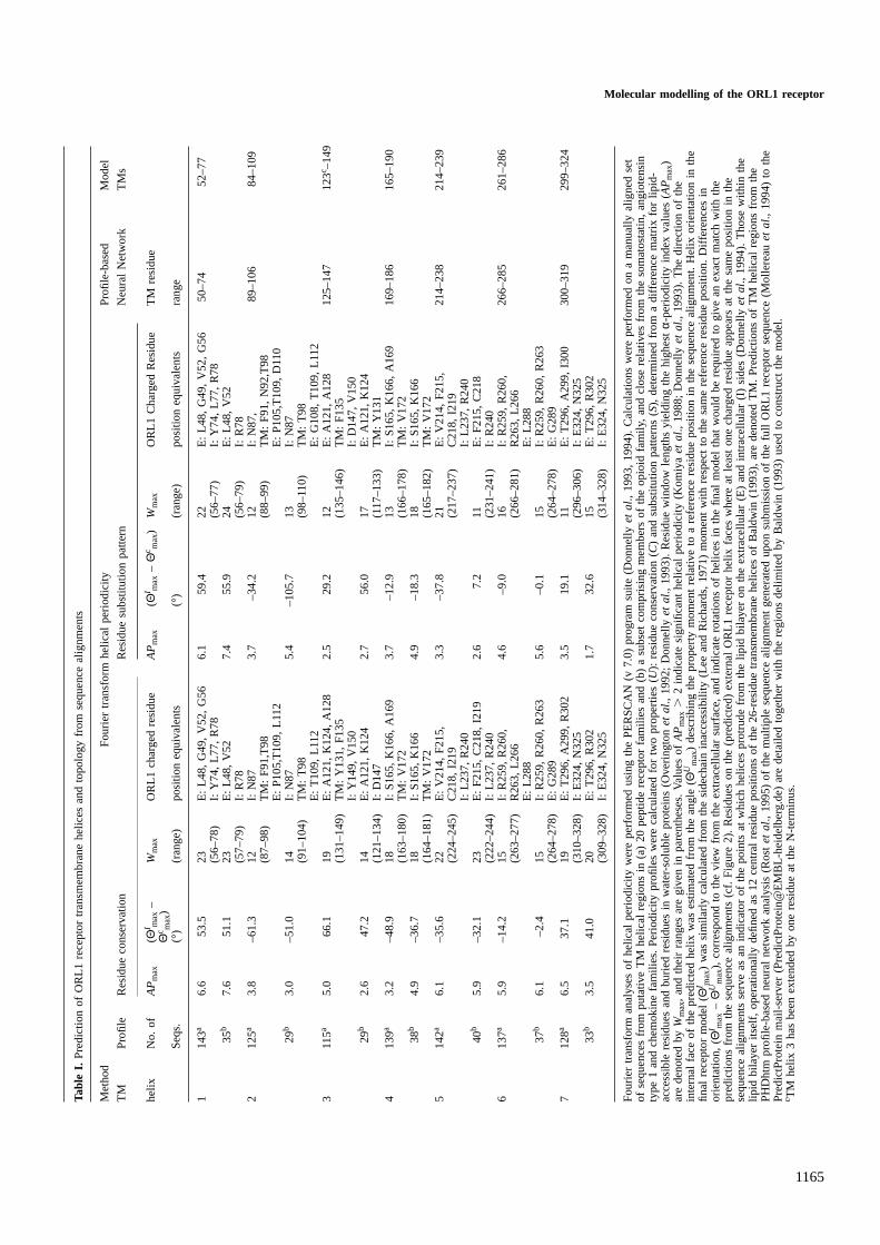
analysis of Baldwin (1993). These were found to be in generallygood agreement with predictions made by the PHDhtm (Rostet al., 1995) neural network program from a multiple sequencealignment, and with the appearance of charged residues atsequence alignment positions corresponding to external (lipidaccessible) helix faces, as determined by PERSCAN v7.0(Donnelly et al., 1993, 1994) Fourier transform periodicityanalyses of amino acid residue properties (Table I). An initialmodel of the ORL1 receptor was constructed by superpositionof helices with ideal geometry onto the Cα co-ordinates of theHerzyk and Hubbard (1995) template according to the sequencealignment with rhodopsin (Figure 1). Visual inspection ofthe model indicated that five (1, 3, 5–7) TM helices wereappropriately orientated with ligand accessible residues, asdeduced from collated single point site-directed mutagenesisdata for the opioid receptor structural family (Table II), on theinside of the helical bundle. TM helices 2 and 4 were rotatedaround their axes by150° and 190°, respectively, whenviewed from the extracellular surface, to best satisfy thiscriterion. Checks were also made that the model adequatelymet inter-helical residue proximity constraints, inferred fromcorrelated site-directed mutagenesis studies of several GPCRsystems (Table III).
In the next stage of model building, the helices wereextended by one turn at either end, and the sidechain conforma-tions manually adjusted to relieve poor non-bonded stericcontacts and to optimize potentially favourable sidechain–sidechain and sidechain–mainchain interactions. Following thepre-minimization of added hydrogen atoms, residue sidechainswere energy minimized to a r.m.s. energy gradient of 0.05 kcalmol–1 Å–1 with all mainchain atoms held fixed. The entire TMcore region was then minimized to a final r.m.s. energy gradientof 0.1 kcal mol–1 Å–1 in the absence of any positionalconstraints. All the residues in the helical extensions werethen excised apart from Cys123 at the interface of the firstextracellular loop (EL1) and the third TM helix. The r.m.s.d.
Molecular modelling of the ORL1 receptorTa
ble
I.P
redi
ctio
nof
OR
L1re
cept
ortr
ansm
embr
ane
helic
esan
dto
polo
gyfr
omse
quen
ceal
ignm
ents
Met
hod
Fou
rier
tran
sfor
mhe
lical
perio
dici
tyP
rofil
e-ba
sed
Mod
el
TM
Pro
file
Res
idue
cons
erva
tion
Res
idue
subs
titut
ion
patte
rnN
eura
lNet
wor
kT
Ms
helix
No.
ofA
Pm
ax(Θ
I max
–W
max
OR
L1ch
arge
dre
sidu
eA
Pm
ax(Θ
I max
–Θ
c max
)W
max
OR
L1C
harg
edR
esid
ueT
Mre
sidu
eΘ
c max
)S
eqs.
(°)
(ran
ge)
posi
tion
equi
vale
nts
(°)
(ran
ge)
posi
tion
equi
vale
nts
rang
e
114
3a6.
653
.523
E:
L48,
G49
,V
52,
G56
6.1
59.4
22E
:L4
8,G
49,
V52
,G
5650
–74
52–7
7(5
6–78
)I:
Y74
,L7
7,R
78(5
6–77
)I:
Y74
,L7
7,R
7835
b7.
651
.123
E:
L48,
V52
7.4
55.9
24E
:L4
8,V
52(5
7–79
)I:
R78
(56–
79)
I:R
782
125a
3.8
–61.
312
I:N
873.
7–3
4.2
12I:
N87
,89
–106
84–1
09(8
7–98
)T
M:
F91
,T98
(88–
99)
TM
:F
91,
N92
,T98
E:
P10
5,T
109,
L112
E:
P10
5,T
109,
D11
029
b3.
0–5
1.0
14I:
N87
5.4
–105
.713
I:N
87(9
1–10
4)T
M:
T98
(98–
110)
TM
:T
98E
:T
109,
L112
E:
G10
8,T
109,
L112
311
5a5.
066
.119
E:
A12
1,K
124,
A12
82.
529
.212
E:
A12
1,A
128
125–
147
123
c –14
9(1
31–1
49)
TM
:Y
131,
F13
5(1
35–1
46)
TM
:F
135
I:Y
149,
V15
0I:
D14
7,V
150
29b
2.6
47.2
14E
:A
121,
K12
42.
756
.017
E:
A12
1,K
124
(121
–134
)I:
D14
7(1
17–1
33)
TM
:Y
131
413
9a3.
2–4
8.9
18I:
S16
5,K
166,
A16
93.
7–1
2.9
13I:
S16
5,K
166,
A16
916
9–18
616
5–19
0(1
63–1
80)
TM
:V
172
(166
–178
)T
M:
V17
238
b4.
9–3
6.7
18I:
S16
5,K
166
4.9
–18.
318
I:S
165,
K16
6(1
64–1
81)
TM
:V
172
(165
–182
)T
M:
V17
25
142a
6.1
–35.
622
E:
V21
4,F
215,
3.3
–37.
821
E:
V21
4,F
215,
214–
238
214–
239
(224
–245
)C
218,
I219
(217
–237
)C
218,
I219
I:L2
37,
R24
0I:
L237
,R
240
40b
5.9
–32.
123
E:
F21
5,C
218,
I219
2.6
7.2
11E
:F
215,
C21
8(2
22–2
44)
I:L2
37,
R24
0(2
31–2
41)
I:R
240
613
7a5.
9–1
4.2
15I:
R25
9,R
260,
4.6
–9.0
16I:
R25
9,R
260,
266–
285
261–
286
(263
–277
)R
263,
L266
(266
–281
)R
263,
L266
E:
L288
E:
L288
37b
6.1
–2.4
15I:
R25
9,R
260,
R26
35.
6–0
.115
I:R
259,
R26
0,R
263
(264
–278
)E
:G
289
(264
–278
)E
:G
289
712
8a6.
537
.119
E:
T29
6,A
299,
R30
23.
519
.111
E:
T29
6,A
299,
I300
300–
319
299–
324
(310
–328
)I:
E32
4,N
325
(296
–306
)I:
E32
4,N
325
33b
3.5
41.0
20E
:T
296,
R30
21.
732
.615
E:
T29
6,R
302
(309
–328
)I:
E32
4,N
325
(314
–328
)I:
E32
4,N
325
Fou
rier
tran
sfor
man
alys
esof
helic
alpe
riodi
city
wer
epe
rfor
med
usin
gth
eP
ER
SC
AN
(v7.
0)pr
ogra
msu
ite(D
onne
llye
ta
l.,19
93,
1994
).C
alcu
latio
nsw
ere
perf
orm
edon
am
anua
llyal
igne
dse
tof
sequ
ence
sfr
ompu
tativ
eT
Mhe
lical
regi
ons
in(a
)20
pept
ide
rece
ptor
fam
ilies
and
(b)
asu
bset
com
pris
ing
mem
bers
ofth
eop
ioid
fam
ily,
and
clos
ere
lativ
esfr
omth
eso
mat
osta
tin,
angi
oten
sin
type
1an
dch
emok
ine
fam
ilies
.P
erio
dici
typr
ofile
sw
ere
calc
ulat
edfo
rtw
opr
oper
ties
(U
):re
sidu
eco
nser
vatio
n(
C)
and
subs
titut
ion
patte
rns
(S)
,de
term
ined
from
adi
ffere
nce
mat
rixfo
rlip
id-
acce
ssib
lere
sidu
esan
dbu
ried
resi
dues
inw
ater
-sol
uble
prot
eins
(Ove
ringt
one
ta
l.,19
92;
Don
nelly
et
al.,
1993
).R
esid
uew
indo
wle
ngth
syi
eldi
ngth
ehi
ghes
tα-
perio
dici
tyin
dex
valu
es(AP
max
)ar
ede
note
dby
Wm
ax,
and
thei
rra
nges
are
give
nin
pare
nthe
ses.
Valu
esof
AP
max
.2
indi
cate
sign
ifica
nthe
lical
perio
dici
ty(K
omiy
aeta
l.,19
88;
Don
nelly
et
al.,
1993
).T
hedi
rect
ion
ofth
ein
tern
alfa
ceof
the
pred
icte
dhe
lixw
ases
timat
edfr
omth
ean
gle
(Θ
Um
ax)
desc
ribin
gth
epr
oper
tym
omen
tre
lativ
eto
are
fere
nce
resi
due
posi
tion
inth
ese
quen
ceal
ignm
ent.
Hel
ixor
ient
atio
nin
the
final
rece
ptor
mod
el(ΘI m
ax)
was
sim
ilarly
calc
ulat
edfr
omth
esi
dech
ain
inac
cess
ibili
ty(L
eean
dR
icha
rds,
1971
)m
omen
tw
ithre
spec
tto
the
sam
ere
fere
nce
resi
due
posi
tion.
Diff
eren
ces
inor
ient
atio
n,(Θ
I max
–Θ
Um
ax),
corr
espo
ndto
the
view
from
the
extr
acel
lula
rsu
rfac
e,an
din
dica
tero
tatio
nsof
helic
esin
the
final
mod
elth
atw
ould
bere
quire
dto
give
anex
act
mat
chw
ithth
epr
edic
tions
from
the
sequ
ence
alig
nmen
ts(c
f.F
igur
e2)
.R
esid
ues
onth
e(p
redi
cted
)ex
tern
alO
RL1
rece
ptor
helix
face
sw
here
atle
ast
one
char
ged
resi
due
appe
ars
atth
esa
me
posi
tion
inth
ese
quen
ceal
ignm
ents
serv
eas
anin
dica
tor
ofth
epo
ints
atw
hich
helic
espr
otru
defr
omth
elip
idbi
laye
ron
the
extr
acel
lula
r(E
)an
din
trac
ellu
lar
(I)
side
s(D
onne
llye
ta
l.,19
94).
Tho
sew
ithin
the
lipid
bila
yer
itsel
f,op
erat
iona
llyde
fined
as12
cent
ralr
esid
uepo
sitio
nsof
the
26-r
esid
uetr
ansm
embr
ane
helic
esof
Bal
dwin
(199
3),
are
deno
ted
TM
.P
redi
ctio
nsof
TM
helic
alre
gion
sfr
omth
eP
HD
htm
profi
le-b
ased
neur
alne
twor
kan
alys
is(R
ost
et
al.,
1995
)of
the
mul
tiple
sequ
ence
alig
nmen
tge
nera
ted
upon
subm
issi
onof
the
full
OR
L1re
cept
orse
quen
ce(M
olle
reau
et
al.,
1994
)to
the
Pre
dict
Pro
tein
mai
l-ser
ver
(Pre
dict
Pro
tein
@E
MB
L-he
idel
berg
.de)
are
deta
iled
toge
ther
with
the
regi
ons
delim
ited
byB
aldw
in(1
993)
used
toco
nstr
uct
the
mod
el.
c TM
helix
3ha
sbe
enex
tend
edby
one
resi
due
atth
eN
-ter
min
us.
1165

C.M.Topham et al.
Table II. Opioid receptor family site-directed mutagenesis data used to orientate ORL1 receptor transmembrane helices
Transmembrane Mutation Opioid receptor Maximal effect on ligand ORL1 receptor Referencehelix subtype binding/activity (-fold) residue
TM 1 L59S ORL1 ` L59 Menget al. (1996)TM 2 D95N δ 300 D97 Konget al. (1994)
D105N κ 200 D97 Hjorthet al. (1996)D114N µ .1000 D97 Surrattet al. (1994)D114A µ 400 D97 Chakrabartiet al. (1997)T109A κ 70 L101 Hjorth at al. (1996)
TM3 D128N δ .1000 D130 Befortet al. (1996a)D138N κ ` D130 Konget al. (1993)D147A µ 250 D130 Befortet al. (1996a)Y129A δ 230 Y131 Befortet al. (1996b)N150A µ 20 N133 Mansouret al. (1997)
TM4 W173A δ 45 W175 Befortet al. (1996b)S177L δ Antagonist→ Agonist S179 Claudeet al. (1996)S196L κ Antagonist→ Agonist S179 Claudeet al. (1996)S196L µ Antagonist→ Agonist S179 Claudeet al. (1996)
TM 5 A216K ORL1 20 A216 Menget al. (1996)TM 6 W274A δ 16 W276 Befortet al. (1996b)
H297A µ ` Q280 Mansouret al. (1997)Q280H ORL1 135 Q280 Mollereauet al. (1996)W284A δ 25 Q286 Valiquetteet al. (1996)E297K κ 140 Q286 Hjorthet al. (1995)
TM7 T305I ORL1 35 T305 Menget al. (1996)Y308F δ 14 Y309 Befortet al. (1996b)Y326F µ ` Y309 Mansouret al. (1997)
Single-site mutants with significantly altered agonist or antagonist binding and/or bioactivity properties are listed. Sidechain positions of (equivalent) residuesin the ORL1 receptor model are orientated towards the centre of the transmembrane helical bundle (cf. Figure 2).
with respect to equivalent Cα positions in the bovine rhodopsinmodel template was 1.41 Å, and 0.26 Å when TM helices 2and 4 were removed from the calculation.
Modelling extra- and intracellular loops in the ORL1receptorThe six loop sections interconnecting successive TM helices(see Figure 1) of the minimized receptor core framework werethen added. With the exception of EL2, which was mainlymanually built by an iterative process of interactive graphicsand energy minimization, ensembles of candidate loop frag-ments compatible with the geometry of a three-residue overlapwith the TM model core were first identified from a databaseof .1100 protein structures sharing up to 95% sequenceidentity using the COMPOSER protein modelling suite(Sutcliffe et al., 1987a,b; Blundellet al., 1988; Tophamet al.,1990; Srinivasan and Blundell, 1993). Protein fragments werejoined to the core using a ring closure algorithm(F.Eisenmenger, personal communication), or where thisresulted in significant changes to the internal loop geometry,melded directly to the framework (Blundellet al., 1988;Sutcliffe, 1988). Minor adjustments in sidechain conformationswere made where necessary, before minimization of individualloops to an r.m.s. energy gradient of 0.05 kcal mol–1 Å–1.Mainchain atoms of the TM core were normally held fixed,but flanking residues were occasionally released to facilitateconvergence. Fresh copies of the minimized TM region co-ordinates were used to process the loops. Candidate loop co-ordinate sets were excised and stored for later display.
The first stage in modelling of the EL2 loop was theconstruction of the conserved disulphide bridge connectingCys123, at the N-terminus end of TM helix 3, and Cys200 inthe EL2 loop (Figure 1). The bridge was built using one ofthe nine preferred sidechain rotamer combinations detailed bySrinivasanet al. (1990): χ1 Cys1235 –60°, χ2 Cys1235
1166
175°, χ1 Cys200 5 –60°, χ2 Cys200 5 –70°, andχss 5190°. The peptide chain was manually extended by oneresidue on the C-terminal side of Cys200 and three residueson the other side, aided by the SYBYL peptide buildingmodule. Residues in low potential energy conformations werealso added by hand to the termini of TM helices 4 and 5.Connecting peptide fragments were then sought in the proteindatabase using COMPOSER for a seven-residue (202–208)section (see Table IV), and a shorter section (194–196) on theN-terminal side of the disulphide bridge. Sequence alignmentshows hydrophobic residues at positions 198 and 202 (ORL1receptor numbering) in the opioid receptor family (Figure 1).Torsion angle adjustments were made in order to maximizethe buried surface area of the sidechains of Ile198 and Val202,calculated according to Lee and Richards (1971). Furtherstructural modifications to the loop and sidechain conforma-tions of residues in the TM core were made to avoid trapping ofthe loop in a high energy local minimum during minimization.Harmonic distance and dihedral angle constraints were intro-duced to maintain the structural integrity of the disulphidebridge, and to ensure good proline geometry at positions 205and 207. The constraints were gradually released, and the EL2loop minimized to a final r.m.s. energy gradient of 0.05 kcalmol–1 Å–1. As before, sidechain atoms of the TM frameworkwere free to move, but the mainchain was held fixed.
Final model refinementOnce all the loop sections had been assembled, they were simul-taneously displayed together with the minimized TM regionco-ordinates. A final selection of loop fragments was made(Table IV) on the basis of mutual conformational compatibility.Poor steric contacts between loops were relieved by manualtweaking of mainchain and sidechain torsion angles, beforeminimization of the intra- and extracellular loop domains asseparate groups to an energy gradient of 0.05kcal mol–1Å–1. The

Molecular modelling of the ORL1 receptor
Tabl
eIII
.In
ter-
helic
alre
sidu
ecl
uste
rsin
ferr
edfr
omG
PC
Rpr
otei
nen
gine
erin
gda
ta
Str
uctu
ral
Pro
xim
alG
PC
RE
quiv
alen
tS
elec
ted
inte
r-at
omic
dist
ance
sC
omm
ent
Ref
eren
ceE
lem
ent
Res
idue
sO
RL1
Res
idue
inO
RL1
rece
ptor
mod
el(Å
)
TM
2N
87G
onad
otro
pin-
rele
asin
gD
97D
97(Cα )-
(Cα )
N31
58.
8P
utat
ive
Na1
bind
ing
site
:Z
houe
ta
l.(1
994)
TM
7D
318
horm
one
N31
5D
97(Oδ1
)-(N
δ2)
N31
55.
2In
timat
eA
sp-A
snio
n-pa
ir,or
TM
2D
120
Ser
oton
in5-
HT 2A
D97
over
allc
harg
eco
nser
vatio
nS
ealfo
ne
ta
l.(1
995)
TM
7N
376
N31
5re
quire
men
tsin
pola
rre
gion
.T
M1
T37
m5
Mus
carin
icY
58Y
58(Cα )
-(C
α )R
302
9.2
Res
tora
tion
oflig
and
bind
ing
Liuet
al.
(199
5)T
M7
H47
8R
302
Y58
(Cβ )-
(Cβ )
R30
27.
4in
m2-
m5
chim
era.
TM
5A
204
α 1b
Adr
ener
gic
A21
6A
216
(Cα )-
(Cα )
V28
39.
5C
o-op
erat
ive
ligan
dbi
ndin
g.H
waet
al.
(199
5)T
M6
L314
V28
3A
216
(Cβ )
-(C
β )V
283
7.6
TM
2G
90R
hodo
psin
L104
L104
(Cα )-
(Cα )
Y30
98.
8Ly
s29
6-G
lu11
3sa
ltbr
idge
Raoe
ta
l.(1
994)
TM
3E
113
V12
6L1
04(Cα )
-(C
β )Y
309
6.9
disr
uptio
nin
G90
Dm
utan
t:T
M7
A29
2T
305
V12
6(C
α )-
(Cα )
T30
58.
3D
90su
bstit
utes
for
E11
3T
M7
K29
6Y
309
V12
6(C
β )-
(Cβ )
T30
56.
5S
chiff
base
coun
terio
n.T
M5/
EL2
E19
3Ta
chyk
inin
NK
1G
212
His
tidin
ere
plac
emen
tto
Elli
ngeta
l.(1
995)
TM
5H
197
A21
6cr
eate
Zn21
bind
ing
site
.T
M6/
EL3
Y27
2G
287
TM
5/E
L2D
223
κ-op
ioid
G21
2T
hirs
trup
et
al.
(199
6)T
M5
K22
7A
216
G21
2(Cα )
-(C
α )G
287
10.5
TM
6/E
L3A
298
G28
7A
216
(Cα )-
(Cα )
G28
710
.7T
M5
V20
4R
hodo
psin
A21
6A
216
(Cβ )-
(Cα )
G28
79.
7Te
rtia
ryco
ntac
tm
appi
ngby
Yuet
al.
(199
5)T
M6/
EL3
F27
6G
287
di-s
ulph
ide
brid
gefo
rmat
ion
TM
5/E
L2N
200
G21
2T
M6/
EL3
F27
6G
287
TM
3N
109
Tach
ykin
inN
K1
I127
I127
(Cα )-
(Cα )
G21
215
.1E
ngin
eere
dZ
n21
bind
ing
site
.E
lling
et
al.
(199
6)T
M5/
EL2
E19
3G
212
I127
(Cβ )-
(Cα )
G21
213
.5T
M2/
EL1
Y92
Tach
ykin
inN
K1
I111
I111
(Cα )-
(Cα )
V12
612
.6E
ngin
eere
dZ
n21bi
ndin
gsi
te.
Elli
nge
ta
l.(1
996)
TM
3H
108
V12
6I1
11(C
β )-
(Cβ )
V12
610
.2
The
com
pend
ium
indi
cate
sO
RL1
rece
ptor
resi
due
posi
tions
indi
ffere
ntst
ruct
ural
elem
ents
that
can
beex
pect
edto
bepr
oxim
al(c
f.F
igur
e3)
.T
hein
ter-
atom
icdi
stan
ces
corr
espo
ndto
the
unlig
ande
dre
cept
orst
ruct
ure.
Inte
r-at
omic
dist
ance
sin
the
OR
L1–n
ocic
eptin
com
plex
dono
tdi
ffer
sign
ifica
ntly
.D
efini
tions
ofth
est
ruct
ural
elem
ents
are
give
nin
Fig
ure
1.
1167

C.M.Topham et al.
Table IV. Protein fragments used in the modelling of extra- and intra-cellular loop regions of. the ORL1 receptor
ORL1 Protein Residue Sequence Six-residue Loop closure Average∆Loop fragment range framework average∆ r.m.s.d.a
region overlap r.m.s.d. φ, ψ [Å][Å] [°]
EL1 ORL1 110–122 DILLGFWPFGNAL 0.59 7.0 1.91CSN 95–107 LLDLCGRKFSVKT
ORL1 113–117b ---LGFWP----- 0.66 24.7 1.63APP 147–151 ---SLAQP-----
EL2 ORL1 202–208c VEIPTPQ 0.61 13.5 1.71MMQ 240–246 YGNGDPQ
EL3 ORL1 287–298 GLGVQPSSETAV 0.56 6.1 1.31BCS (A) 190–201 EFWWNHGIVSDD
IL1 ORL1 78–83 RHTKMK 0.66 –d –d
1APA 248–253 DIEPDV
IL2 ORL1 150–164 VAICHPIRALDVRTS 1.17 5.6 2.61DPN (A) 76–90 EVDDFVASVEIVKQV
IL3 ORL1 240–259 RRLRGVRLLSGSREKDRNLR 0.73 2.7 2.51MMO (G) 92–111 DGTVAKMNAAKDKWEAEKIH
Operational definitions and residue numbering of structural elements in the ORL1 receptor are given in Figure 1. Protein fragments are numbered according tothe Brookhaven Protein Data Bank co-ordinate files (Bernsteinet al., 1977; Abolaet al., 1987), identified by the four-letter code and, where applicable chainidentifier, shown in parentheses.aR.m.s. deviations refer to main-chain Cα positions.bResidues 113–117 in EL1 (underlined) were remodelled using a ‘collar’ extension procedure (see Srinivasan and Blundell, 1993) in which a five-residuefragment originating from the casein kinase 1 (1CSN, 95–107) was removed, and a more suitable fragment from penicillopepsin (3APP, 143–151), inserted.cFlanking EL2 loop residues (191–201; 209–213) were manually built.dLoop melding procedure (Sutcliffe, 1988) used.
loopmainchainatomswerefirstheldfixed,and thenreleased,andthe minimization re-started. Mainchain atoms of the TM corewere held fixed throughout, but sidechain atoms were free tomove. A copy of the receptor co-ordinates was kept at thispoint (stage 1), before final energy minimization to a r.m.s.convergence gradient of 0.1kcal mol–1Å–1 in the absence of anypositional constraints (stage 2).
In situ modelling of nociceptin binding to the ORL1 receptorConstruction of the nociceptin-ORL1 receptor complex startedwith the manual docking of selected amino acid residues intothe refined (stage 2) receptor molecule, guided by site-directedmutagenesis and other experimental data. Inspection of theORL1 receptor model revealed the presence of two hydro-phobic pockets in a cavity formed by TM helices 3, 5, 6 and7, corresponding to the conserved transmembrane opioidbinding site mapped in theδ- (Befort et al., 1996a,b) andµ-receptors (Mansouret al., 1997). Both pockets are conservedto a large extent in the ORL1 receptor, and Fenget al. (1998)have shown that mutation of five residues in this vicinity(Ala216, Val279, Gln280, Val281 and Thr305) to their entirelyconserved opioid receptor counterparts will restore a functionalopioid binding site. On the basis of the clear similarity betweenthe N-terminal FGGF sequence of nociceptin and the opioidYGGF ‘message’ sequence, nociceptin-(1-4) can be assumedto bind in the vestigial ‘opioid binding pocket’ of the ORL1receptor, with the sidechains of F1 and F4 occupying the twoaromatic pockets.
Mutation of Gln280, which is located on the rear wall ofthe F1 pocket in TM helix 6, to histidine, increases the affinityof the ORL1 receptor for lofentanil by eightfold (Mollereauet al., 1996). Most probably the lofentanil phenylpropanamide
1168
group binds in the F1 pocket, enabling the protonated (N1)piperidine ring nitrogen to hydrogen bond with the entirelyconserved Asp130 in TM helix 3. The increase in affinity of theQ280H mutant can then be ascribed to improved electrostaticinteractions of the carbonyl oxygens of the phenylpropanamidemoiety and the COOCH3 substituent at position 4 of thepiperidine ring with the histidine imidazole ring. Cometta-Morini et al. (1992) have shown both oxygens to be goodproton accepting centres in AM1 semi-empirical quantummechanics calculations. The presence of physically analogousgroups in lofentanil and the protonated nociceptin F1 residuesuggests that they might adopt similar spatial dispositions inligand complexes with the receptor. The protonated nitrogen,carbonyl carbon and phenyl ring centroid of phenylalanine ofthe (χ1 5 180°; χ2 5 90°) sidechain rotamer can be fitted tothe N1, COOCH3 carbonyl carbon and phenylpropanamidering centroid of a HF/6-31G* geometry optimized lofentanilstructure (C.M.Topham and G.Poda, unpublished results) withan r.m.s.d. of 0.62 Å. A phenylalanine residue with thissidechain conformation was therefore docked into the receptorwith the F1 carbonyl group orientated towards Gln280, andthe protonated nitrogen donating a hydrogen bond to theAsp130 sidechain. A second phenylalanine residue (F4) waspositioned in the other hydrophobic pocket closer to theextracellular surface, separated from the F1 pocket by Phe220.The two residues were then linked by glycines, and theN-terminal FGGF tetrapeptide energy minimized, with thereceptor sidechains free to move, and harmonic distanceconstraints imposed to maintain hydrogen bonding to Asp130.
The positively charged nociceptin-(8-13) core, carryingarginines at positions 8 and 12, the replacement of which by

Molecular modelling of the ORL1 receptor
uncharged residues adversely affects nociceptin affinity andactivity (Dooley and Houghten, 1996; Reinscheidet al., 1996;Lapalu et al., 1997), is assumed to interact with the acidicEL2 loop, shown to be essential for activation by nocicep-tin (Mollereau,C., Moule´dous,L., Lapalu,S., Cambois,G.,Moisand,C., Butour,J.-L. and Meunier,J.-C., manuscript sub-mitted). The nociceptin-(12-14) section (RKL) was manuallybuilt into the surface cavity bounded by the EL2 loop suchthat the sidechains of R12 and K13 were able to ion pair withglutamate residues 196 and 194, respectively, and the L14sidechain packed in between Pro207 and Tyr210. The tripeptidewas energy minimizedin situ with the backbone atoms of thereceptor held fixed. Potential seven-residue (5–11) connectingfragments with satisfactory three-residue overlap geometrywere then searched for in the protein structure database usingCOMPOSER. These were simultaneously displayed, and afragment selected that clashed least with the receptor. A three-residue (15–17) tailpiece was added, and capped with an NMegroup to eliminate C-terminus charge effects in a part of theligand known not to be important for biological activity.
A stagewise refinement procedure was adopted in order toidentify an energy minimum for nociceptin-(1-17), whilstcausing minimum disturbance to the transmembrane core ofthe receptor. Selected adjustments in sidechain conformationsof the peptide and the receptor were first made, before energyminimization of the ligand to an energy gradient of 0.15 kcalmol–1 Å–1 with the mainchain atoms of the receptor held fixed,but the sidechains free to move. The entire system was thenminimized to an energy gradient of 0.05 kcal mol–1 Å–1 withoutpositional restraints. The nociceptin molecule was excised anddocked back into a copy of the refined (stage 2) apo-receptorco-ordinate set, and the procedure repeated twice more. Allthree extracellular loops were then removed and melded backonto a stage 1 copy of the receptor TM core (plus intracellularloops), by energy minimization to a gradient of 0.05 kcalmol–1 Å–1 with the remaining receptor backbone atoms heldfixed. The refined peptide ligand was docked once more intothe receptor, and additional minor changes made to sidechainconformations. The extracellular loops were then re-minimizedto a r.m.s. energy gradient of 0.1 kcal mol–1 Å–1 with both thenociceptin and remaining receptor backbone atoms held fixed,and all sidechains free to move. Finally the entire system wasenergy minimized to a r.m.s. gradient of 0.1 kcal mol–1 Å–1 inthe absence of any positional constraints.
Structure–sequence fitness of loop regions
Compatibility of the modelled ORL1 receptor loop regionswith their primary sequences was determined using the windowaveraging facility in the HARMONY (v 0.7) computer program(Tophamet al., 1994), incorporating a modified scoring systemdescribed below. Environment-dependent amino acid propen-sities are assigned at each position in a protein fold from a[216 structural environment (εj)321 residue type (r i)] two-dimensional table. The propensity table was calculated fromobserved frequencies of unique residue/environment combina-tions at alignment positions in a structural alignment databaserelease 5a (Overingtonet al., 1990, 1993; Sˇali and Overington,1994). Conditional probabilities of finding a particular residuetype in a given environment,p(r i/εj), are calculated by cor-recting for the normalized frequency of residue type occurrencein the global data set and smoothing of the environment-dependent probabilities (Tophamet al., 1994). A total of72 451 residue occurrences were recorded using the full
1169
database comprising 576 proteins/protein domains in 126families, following removal of two membrane protein families.In common with statistical mechanics treatments of observedfrequencies of occurrence of amino acid sequence and structuralfeatures in proteins (Sippl, 1993a,b; Rooman and Wodak,1995), the propensities are now first compared to a suitablereference state, logarithmically transformed and then summedover the length of the entire fold:
p(ri / εj) i 5 1, 21E(Σ)
score5Σi j
Nij · In ( ) { (1)j 5 1, 216p(ri)
whereNij is the number of residues of typei in environmentj, and p(ri) is the probability of finding a residuei in anyenvironment, and is the same for all residue types (i.e. 1/2150.046) since the residue propensities are pre-adjusted for thenormalized frequency of residue type occurrence in the globaldata set. In the case of a globular protein, the sequence/structurefitness of the overall fold can be assessed by comparing thesummed score, (E(Σ)
score), against a calibration curve constructedusing experimentally determined structures. Application of thisapproach, in which environmental propensities have beencalculated from a data set of soluble proteins, would beinappropriate for a membrane protein. However, the environ-mental features of hydrogen bonding, sidechain accessibilityand seven mainchain conformational classes outside of second-ary structural elements (Tophamet al., 1993) used to calculatethe propensity table are all local in nature. Plots ofE(Σ)
score asa function of chain length are linear, pass close to the origin,and do not show significant protein size-dependent effects thatwould be expected to result from the use of longer rangephysical features such as, for example, inter-residue distanceas a function of linear separation in the amino acid sequence.It is therefore possible to calculate a meaningful averageresidue score (E(Av.)
score) from the calibration curve, and this mayreasonably be used to assess the structural integrity of loopregions at the receptor surface. A best-fitE(Av.)
score value of0.65 per residue was determined from an unweighted linearregression analysis (r 5 0.97) using a calibration set of highresolution crystallographic structures (Tophamet al., 1994).
The conformational structural integrity of loop regions canbe probed using by averaging propensity scores (E(n)
score) at allpositions in a moving window of lengthn, provided thatn issufficiently small so as not to be unduly influenced bycontributions from residues in the transmembrane regions.Values of (E(5)
score) were calculated at the centre (k 5 0) of each(n 5 5) five-residue window:
p(ri / εj)/n ;E(n)
score 5 ln [ Σk
ln ( )k]
p(ri)
k 5 –12(n–1), ..., –1,0,1, ...,12(n–1), (2)
and plotted as a function of loop residue position.
ResultsExperimental support for the ORL1 receptor modelA three-dimensional structure of the human ORL1 receptor(residues 50–276) has been built. The receptor model is basedlargely on the TM helical bundle bovine rhodopsin templatederived by Herzyk and Hubbard (1995), with rotations appliedto TM helices 2 (150°) and 4 (190°) during the early stagesof modelling. The r.m.s. difference over 182 Cα positions

C.M.Topham et al.
Fig. 2. Triptic stereo view of the ORL1 receptor transmembrane helical bundle. Sidechains of (topologically equivalent) residues inferred from single pointsite-directed mutagenesis data as being important for opioid receptor family function (Table II) are shown in heavy typeface. The diagram was prepared usingthe SETORPLOT and SETOR programs (Evans, 1993).
comprising the TM helix framework (Figure 1) of the apo-receptor compared with the starting template is 1.53 Å, and1.64 Å for the receptor complexed with nociceptin. The sevenTM helices are arranged sequentially and anti-clockwise whenviewed from the extracellular surface (Figure 2). Mutatedresidue positions in the ORL1 receptor or the three opioidreceptors yielding significant (.14-fold) changes to eitherbinding and/or activity properties with respect to at least oneligand–receptor system (Table II) are highlighted in Figure 2.The residues are orientated towards the centre of the helicalbundle, as would be expected in order for them to be accessibleto ligand.
The orientations of TM helix 4, 5, 6 and 7 are in goodaccord with the directions of residue substitution patternmoments, calculated from the peptide receptor multiplesequence alignments (Table I) using the Fourier transformmethods described by Donnellyet al. (1993, 1994). Whenresidue conservation is used to calculate helical periodicity,good agreement is obtained for TM helix 6, but is somewhatpoorer for helices 4, 5 and 7 (yet still within 37–49°). Thecalculated property profile moments for TM helices 2 and 3are less self-consistent, although in both cases best agreementwith the model residue sidechain inaccessibility moment (towithin 29° and 34°, respectively) is obtained for residuesubstitution pattern profiles using the full peptide GPCRsequence alignment data set. A clockwise rotation of TMhelix 1 (viewed from the extracellular surface) by 51–59°would be required to obtain agreement with the residue propertyprofile moments calculated from the sequence alignment. Thishowever was not done in order to permit Leu59 to be orientatedtowards the centre of the TM bundle. Mutation of this residueto a serine abolishes binding of iodinated [Y14]-nociceptin tothe ORL1 receptor (Menget al., 1996). Independent rotationof TM helix 1 would also adversely affect the proximity ofthe Tyr58 and Arg302 (TM helix 7) sidechains, shown inFigure 3 to be close to one another. Direct interaction of thecorresponding Thr37 and His478 residues in TM helices 1 and7 of the m5 muscarinic receptor has been demonstrated bypoint-site restoration of function in m2–m5 receptor chimera(Liu et al., 1995).
The residue property profiles identify a number of lipidfacing charged residue positions in the peptide GPCR align-ments of TM helices 2, 3 and 4. However, charged residuesdo not occur at these positions in the ORL1 receptor sequence(Table I), nor indeed do they in the model itself, as determinedby Fourier transform analysis of relative sidechain accessibility
1170
Fig. 3. ORL1 receptor model. TM helices are coloured green and yellow.Surface loops are shown in red, and the conserved disulphide bridge,connecting Cys200 (EL2) and Cys123 at the EL1 loop/TM3 helix interface(Figure 1), in yellow. The highlighted (equivalent ORL1 receptor) residueclusters have been inferred to be proximal from site-directed mutagenesisexperiments carried out in other GPCR systems (see Table III). The imagewas produced using the SETOR and SETORPLOT molecular graphicsprograms (Evans, 1993).
profiles. Taking the model sidechain accessibility profiles as areference, prominently lipid-exposed residue positions carryingcharged residues are observed in TM helix 2 of the vasopressin-like (at positions 91 and 92, ORL1 receptor numbering) andthrombin receptor families (position 92). None is observed inthe other TM helices.

Molecular modelling of the ORL1 receptor
In addition to the proximal Tyr58–Arg302 residue pair, otherinter-helical residue clusters, inferred from correlated site-directed mutagenesis studies in a variety of GPCR systems,are present in the model (Figure 3). Details of these clusters,together with selected inter-atomic distances in the apo-receptor, are summarized in Table III. The proximity of residuesin several different TM helix pairs provides a valuable checkon the relative positions of the helices, and therefore on theintegrity of the receptor bundle. All of the TM helices apartfrom helix 4 are represented in at least one TM helix pair.Structural features and geometry of the loop regionsStudies of structure–activity relationships in the nociceptin–ORL1 receptor system (Dooleyet al., 1997; Guerriniet al.,1997; Lapalu et al., 1997), and ligand selectivity inκ/ORL1 chimeric receptors (Lapaluet al., 1998; Mollereau,C.,Mouledous,L., Lapalu,S., Cambois,G., Moisand,C., Butour,J.-L.and Meunier,J.-C., manuscript submitted) indicate that com-ponents of the extracellular loop domain, and in particular theEL2 loop, are involved in nociceptin binding and receptoractivation. In view of their likely key role, the three extracellular(EL) loops have been built into the model (Figure 3). TheEL1 loop forms a flat span between TM helices 2 and 3, withCys123 of the conserved disulphide bridge located at thejunction with TM helix 3. The longer and more variable EL2loop, comprising seven acidic residues, is arranged around theedge of the cavity formed by TM helices 3, 5, 6 and 7,and proposed nociceptin N-terminal tetrapeptide binding sitedescribed below, to which it is clearly able to control access.Cys200, the disulphide bonded partner of Cys123, is locatedtowards the middle of this loop. The disulphide sidechaingeometry remained within the original conformational domain,and was assessed to be of the highest stereochemical grade bythe MODIP program of Sowdhaminiet al. (1989). Thedisulphide bridge is buried, with,7% relative sidechainaccessibility (Hubbard and Blundell, 1987), as was also com-monly found in a survey of high resolution protein crystalstructures (Srinivasanet al., 1990). The third extracellular loop(EL3) arches between TM helices 6 and 7, packing beneaththe C-terminal portion of EL2. A network of potential hydrogenbonding interactions is observed between residues of the EL2loop and residues of the other two extracellular loops. Thethree intracellular loops, connecting TM helices 1 and 2 (IL1),3 and 4 (IL2), and 5 and 6 (IL3), are also shown in Figure 3.Cross-over contacts have been made between residues at theN-terminal ends of IL2 and IL3, but alternative interactionsbetween these loops are possible.
The overall model geometry was checked using PROCHECK(Laskowskiet al., 1993). No short non-bonded contacts werefound, and the correct chirality was observed at all tetrahedralcarbon atom centres. All 248 non-glycine and non-prolineresidues are within the ‘most favoured’ (90.7%), or ‘addition-ally allowed’ (9.3%) regions of the Ramachandran plot delin-eated by Morriset al. (1992). The side-chain torsion angleswere determined as being inside or better than the expecteddeviations from an ideal (globular) protein structure determinedcrystallographically at 2 Å resolution. Acceptable geometrywas also obtained for the ORL1 receptor in the model complexwith nociceptin, which was refined and minimized semi-independently: no residues were observed in either the ‘disal-lowed’ or ‘generously allowed’ regions of Morriset al. (1992).The disulphide bridge geometry was again of the higheststereochemical grade according to the Sowdhaminiet al.(1989) criteria.
1171
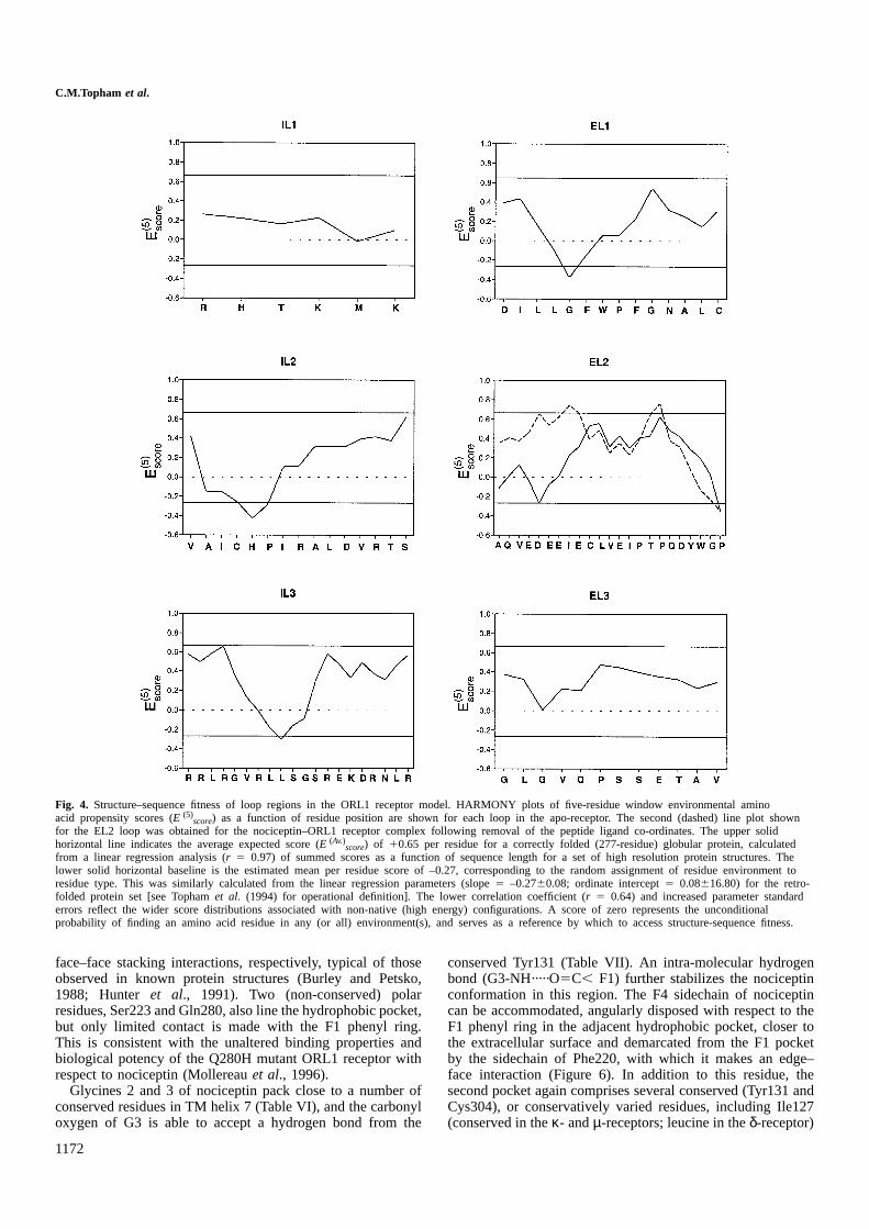
A profiling method (Tophamet al., 1994), incorporating amodified scoring regime, has been used to assess the com-patibility of the loop conformations with their primarysequences. Plots of the (E (5)
score) values as a function ofresidue position for the three extracellular loops are shown inFigure 4. For the most part, the profiles comprise positivescores slightly less than the expected average score of10.65for a residue in a similar sized globular protein. The negativescores in the residue range Leu113–Trp116 of the EL1 loopprofile would normally be indicative of a poorly modelledsection. The trough largely derives from the presence of solventexposed residues at the heart of a run of nine non-polar orhydrophobic residues (ILLGFWPFG). However, this regionwhich also contains a conserved residue quartet (WPFG),possibly contacts the 50-residue N-terminal domain absentfrom the model. Residue sidechains that are apparently access-ible to solvent in the model may thus be buried in thenative receptor protein. Two EL2 loop profiles are shown,corresponding to the unliganded and liganded receptor models,the nociceptin co-ordinates of the latter having been excisedprior to the assignment of residue environments. A high scoringprofile is obtained for the EL2 loop in the complex withnociceptin. The profile for the apo-receptor loop is very similarin the C-terminal region, but dips below zero in the N-terminalsection. The improved profile for the liganded conformer ismainly attributable to an increase in solvent accessibility ofthe Glu197 sidechain which faces the centre of the receptor.Taken together with the geometric analyses, these resultsprovide good evidence that the extracellular loop regions arein general conformationally compatible with their sequences.Profiles for the three intracellular loops are also shown inFigure 4. Troughs occur in the profiles for the IL2 and IL3loops, although these again correspond to exposed regionsbearing hydrophobic residues, making interpretation difficult,since the G-protein and the receptor C-terminal domain areabsent.
Interactions of nociceptin with the ORL1 receptor
Location of the proposed nociceptin binding site within theORL1 receptor is shown in Figure 5. The nociceptin backbonedihedral angles are all in acceptable regions of (φ, ψ) conforma-tional space (Table V). The N-terminal (FGGF) tetrapeptideis positioned within a cavity, formed by elements from TMhelices 3 and 5–7, such that its protonated N-terminus caninteract with the conserved aspartate residue (130) of the TM3helix, as shown in an expanded view of the region (Figure 6).A strikingly high proportion of the receptor residues fallingwithin a 5 Å contact radius of nociceptin-(1-4) are entirelyconserved in the opioid receptor family (Table VI). Thetopology of the FGGF binding site is in good accord with themapping of analogous opioid binding pockets, carried outusing ‘loss of function’ site-directed mutagenesis approachesin the δ- (Befort et al., 1996a,b) andµ-receptors (Mansouret al., 1997), and an inverse ‘gain in function’ approach in theORL1 receptor itself (Fenget al., 1998). Two transmembranearomatic pockets are discernible. The nociceptin F1 sidechainhas been docked into the deeper lying pocket, bounded byTyr131, Met134, Phe220, Phe224, Trp276 and Val279. Ofthese residues, five are conserved in the opioid receptor family,and the valine at position 279 is conservatively replaced byisoleucine in theκ-, µ- andδ-opioid receptors. The F1 phenylring of nociceptin lies between the Phe220 and Trp276 aromaticring systems, making favourable edge–face and displaced
C.M.Topham et al.
Fig. 4. Structure–sequence fitness of loop regions in the ORL1 receptor model. HARMONY plots of five-residue window environmental aminoacid propensity scores (E (5)
score) as a function of residue position are shown for each loop in the apo-receptor. The second (dashed) line plot shownfor the EL2 loop was obtained for the nociceptin–ORL1 receptor complex following removal of the peptide ligand co-ordinates. The upper solidhorizontal line indicates the average expected score (E (Av.)
score) of 10.65 per residue for a correctly folded (277-residue) globular protein, calculatedfrom a linear regression analysis (r 5 0.97) of summed scores as a function of sequence length for a set of high resolution protein structures. Thelower solid horizontal baseline is the estimated mean per residue score of –0.27, corresponding to the random assignment of residue environment toresidue type. This was similarly calculated from the linear regression parameters (slope5 –0.2760.08; ordinate intercept5 0.08616.80) for the retro-folded protein set [see Tophamet al. (1994) for operational definition]. The lower correlation coefficient (r 5 0.64) and increased parameter standarderrors reflect the wider score distributions associated with non-native (high energy) configurations. A score of zero represents the unconditionalprobability of finding an amino acid residue in any (or all) environment(s), and serves as a reference by which to access structure-sequence fitness.
face–face stacking interactions, respectively, typical of thoseobserved in known protein structures (Burley and Petsko,1988; Hunter et al., 1991). Two (non-conserved) polarresidues, Ser223 and Gln280, also line the hydrophobic pocket,but only limited contact is made with the F1 phenyl ring.This is consistent with the unaltered binding properties andbiological potency of the Q280H mutant ORL1 receptor withrespect to nociceptin (Mollereauet al., 1996).
Glycines 2 and 3 of nociceptin pack close to a number ofconserved residues in TM helix 7 (Table VI), and the carbonyloxygen of G3 is able to accept a hydrogen bond from the
1172
conserved Tyr131 (Table VII). An intra-molecular hydrogenbond (G3-NH·····O5C, F1) further stabilizes the nociceptinconformation in this region. The F4 sidechain of nociceptincan be accommodated, angularly disposed with respect to theF1 phenyl ring in the adjacent hydrophobic pocket, closer tothe extracellular surface and demarcated from the F1 pocketby the sidechain of Phe220, with which it makes an edge–face interaction (Figure 6). In addition to this residue, thesecond pocket again comprises several conserved (Tyr131 andCys304), or conservatively varied residues, including Ile127(conserved in theκ- andµ-receptors; leucine in theδ-receptor)
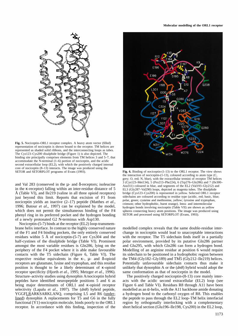
Molecular modelling of the ORL1 receptor
Fig. 5. Nociceptin–ORL1 receptor complex. A heavy atom vector (filled)representation of nociceptin is shown bound to the receptor. TM helices arerepresented as shaded solid ribbons, and the interconnecting loops as tubes.The Cys123–Cys200 disulphide bridge (Figure 1) is also depicted. Thebinding site principally comprises elements from TM helices 3 and 5–7, thataccommodate the N-terminal (1–6) portion of nociceptin, and the acidicsecond extracellular loop (EL2), with which the positively charged internalcore of nociceptin (8–13) interacts. The image was produced using theSETOR and SETORPLOT programs of Evans (1993).
and Val 283 (conserved in theµ- and δ-receptors; isoleucinein the κ-receptor) falling within an inter-residue distance of 5Å (Table VI), and Ile219 (valine in all three opioid receptors)just beyond this limit. Reports that excision of F1 fromnociceptin yields an inactive (2–17) peptide (Mattheset al.,1996; Butouret al., 1997) can be explained by the model,which does not permit the simultaneous binding of the F4phenyl ring in its preferred pocket and the hydrogen bondingof a newly protonated G2 N-terminus with Asp130.
Nociceptin-(5-7) binds at the receptor (EL2) loop-transmem-brane helix interface. In contrast to the highly conserved natureof the F1 and F4 binding pockets, the only entirely conservedresidues within 5 Å of nociceptin-(5-7) are Cys304 and thehalf-cystines of the disulphide bridge (Table VI). Prominentamongst the most variable residues is Gln286, lying on theperiphery of the F4 pocket where it is able make favourablecontacts with the T5 sidechain (Figure 6, Table VI). Therespective residue equivalents in theκ-, µ- and δ-opioidreceptors are glutamate, lysine and tryptophan, and this residueposition is thought to be a likely determinant ofκ-opioidreceptor specificity (Hjorthet al., 1995; Metzgeret al., 1996).Structure–activity studies using dynorphin A/nociceptin hybridpeptides have identified neuropeptide positions 5 and 6 asbeing major determinants of ORL1 andκ-opioid receptorselectivity (Lapaluet al., 1997). The (dn8) hybrid peptide,YGGFLRARKSARKLANQ, comprising L5 and R6 (under-lined) dynorphin A replacements for T5 and G6 in the fullyfunctional [Y1]-nociceptin molecule, binds poorly to the ORL1receptor. In accordance with this finding, inspection of the
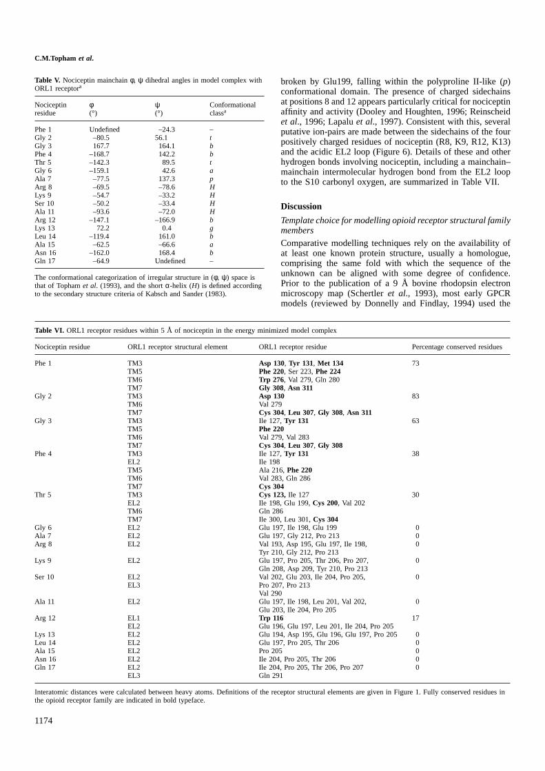
1173
Fig. 6. Binding of nociceptin-(1-13) to the ORL1 receptor. The view showsthe interaction of nociceptin-(1-13), coloured according to atom type (C,grey; O, red; N, blue), with the extracellular termini of receptor TM helices3 (Cys123–Met134), 5 (Pro213–Phe224), 6 (Trp276–Gln286) and 7 (Ile300–Asn311) coloured in blue, and segments of the EL2 (Val193–Gly212) andEL3 (Gly287–Val290) loops, depicted as magenta tubes. The disulphidebridge (Cys123–Cys200) is represented in yellow. Selected ORL1 receptorsidechains are coloured according to residue type (acidic, red; basic, blue;polar, green; cysteine and methionine, yellow; tyrosine and tryptophan,crimson; other hydrophobic, burnt orange). Intra- and intermolecularhydrogen bonds involving nociceptin (Table VII) are shown as yellowspheres connecting heavy atom positions. The image was produced usingSETOR and processed using SETORPLOT (Evans, 1993).
modelled complex reveals that the same double-residue inter-change in nociceptin would lead to unacceptable interactionswith the receptor. The T5 sidechain finds itself in a partiallypolar environment, provided by its putative Gln286 partnerand Glu295, with which Gln286 can form a hydrogen bond.Modelling of an arginine residue at position 6 would requireits sidechain to be positioned in a hydrophobic region betweenthe TM4 (Gly182–Gly189) and TM5 (Gly212–Ile219) helices.Potentially unfavourable sidechain contacts thus make itunlikely that dynorphin A or the (dn8) hybrid would adopt thesame conformation as that of nociceptin in the model.
The positively charged nociceptin-(8-13) core mainly inter-acts with the acidic second extracellular (EL2) loop (seeFigure 6 and Table VI). Residues R8 through A11 have beenmodelled as anα-helix, with the A11 backbone amide donatinga hydrogen bond to the carbonyl oxygen of R8. This enablesthe peptide to pass through the EL2 loop–TM helix interfacialregion by orthogonally interlocking with a complementaryshort helical section (Glu196–Ile198, Cys200) in the EL2 loop,
C.M.Topham et al.
Table V. Nociceptin mainchainφ, ψ dihedral angles in model complex withORL1 receptora
Nociceptin φ ψ Conformationalresidue (°) (°) classa
Phe 1 Undefined –24.3 –Gly 2 –80.5 56.1 tGly 3 167.7 164.1 bPhe 4 –168.7 142.2 bThr 5 –142.3 89.5 tGly 6 –159.1 42.6 aAla 7 –77.5 137.3 pArg 8 –69.5 –78.6 HLys 9 –54.7 –33.2 HSer 10 –50.2 –33.4 HAla 11 –93.6 –72.0 HArg 12 –147.1 –166.9 bLys 13 72.2 0.4 gLeu 14 –119.4 161.0 bAla 15 –62.5 –66.6 aAsn 16 –162.0 168.4 bGln 17 –64.9 Undefined –
The conformational categorization of irregular structure in (φ, ψ) space isthat of Tophamet al. (1993), and the shortα-helix (H) is defined accordingto the secondary structure criteria of Kabsch and Sander (1983).
Table VI. ORL1 receptor residues within 5 Å of nociceptin in the energy minimized model complex
Nociceptin residue ORL1 receptor structural element ORL1 receptor residue Percentage conserved residues
Phe 1 TM3 Asp 130, Tyr 131, Met 134 73TM5 Phe 220, Ser 223,Phe 224TM6 Trp 276, Val 279, Gln 280TM7 Gly 308, Asn 311
Gly 2 TM3 Asp 130 83TM6 Val 279TM7 Cys 304, Leu 307, Gly 308, Asn 311
Gly 3 TM3 Ile 127,Tyr 131 63TM5 Phe 220TM6 Val 279, Val 283TM7 Cys 304, Leu 307, Gly 308
Phe 4 TM3 Ile 127,Tyr 131 38EL2 Ile 198TM5 Ala 216,Phe 220TM6 Val 283, Gln 286TM7 Cys 304
Thr 5 TM3 Cys 123,Ile 127 30EL2 Ile 198, Glu 199,Cys 200, Val 202TM6 Gln 286TM7 Ile 300, Leu 301,Cys 304
Gly 6 EL2 Glu 197, Ile 198, Glu 199 0Ala 7 EL2 Glu 197, Gly 212, Pro 213 0Arg 8 EL2 Val 193, Asp 195, Glu 197, Ile 198, 0
Tyr 210, Gly 212, Pro 213Lys 9 EL2 Glu 197, Pro 205, Thr 206, Pro 207, 0
Gln 208, Asp 209, Tyr 210, Pro 213Ser 10 EL2 Val 202, Glu 203, Ile 204, Pro 205, 0
EL3 Pro 207, Pro 213Val 290
Ala 11 EL2 Glu 197, Ile 198, Leu 201, Val 202, 0Glu 203, Ile 204, Pro 205
Arg 12 EL1 Trp 116 17EL2 Glu 196, Glu 197, Leu 201, Ile 204, Pro 205
Lys 13 EL2 Glu 194, Asp 195, Glu 196, Glu 197, Pro 205 0Leu 14 EL2 Glu 197, Pro 205, Thr 206 0Ala 15 EL2 Pro 205 0Asn 16 EL2 Ile 204, Pro 205, Thr 206 0Gln 17 EL2 Ile 204, Pro 205, Thr 206, Pro 207 0
EL3 Gln 291
Interatomic distances were calculated between heavy atoms. Definitions of the receptor structural elements are given in Figure 1. Fully conserved residues inthe opioid receptor family are indicated in bold typeface.
1174
broken by Glu199, falling within the polyproline II-like (p)conformational domain. The presence of charged sidechainsat positions 8 and 12 appears particularly critical for nociceptinaffinity and activity (Dooley and Houghten, 1996; Reinscheidet al., 1996; Lapaluet al., 1997). Consistent with this, severalputative ion-pairs are made between the sidechains of the fourpositively charged residues of nociceptin (R8, K9, R12, K13)and the acidic EL2 loop (Figure 6). Details of these and otherhydrogen bonds involving nociceptin, including a mainchain–mainchain intermolecular hydrogen bond from the EL2 loopto the S10 carbonyl oxygen, are summarized in Table VII.
Discussion
Template choice for modelling opioid receptor structural familymembers
Comparative modelling techniques rely on the availability ofat least one known protein structure, usually a homologue,comprising the same fold with which the sequence of theunknown can be aligned with some degree of confidence.Prior to the publication of a 9 Å bovine rhodopsin electronmicroscopy map (Schertleret al., 1993), most early GPCRmodels (reviewed by Donnelly and Findlay, 1994) used the

Molecular modelling of the ORL1 receptor
Table VII. Nociceptin intra- and inter-molecular hydrogen bonds
Molecule Donor Acceptor Molecule
Residue Group Group Residue
Nociceptin Phe 1 -NH3(1) (–)Oδ1- Asp 130 ORL1
receptorNociceptin Phe 1 -NH3
(1) (–)Oδ2- Asp 130 ORL1receptor
Nociceptin Gly 3 -NH O5C, Phe 1 NociceptinORL1 Tyr 131 -OH O5C, Gly 3 NociceptinreceptorNociceptin Arg 8 -Nη2H2
(–)Oδ1- Asp 195 ORL1receptor
Nociceptin Arg 8 -NεH (–)Oδ1- Asp 195 ORL1receptor
Nociceptin Arg 8 -NεH (–)Oε2- Glu 197 ORL1receptor
Nociceptin Lys 9 -NζH3(1) O5C, Gln 208 ORL1
receptorNociceptin Ala 11 -NH O5C, Arg 8 NociceptinORL1 Glu 203 -NH O5C, Ser 10 NociceptinreceptorNociceptin Arg 12 -Nη1H2
(–)Oε1- Glu 196 ORL1receptor
Nociceptin Lys 13 -NζH3(1) (–)Oε1- Glu 194 ORL1
receptorNociceptin Lys 13 -NζH3
(1) (–)Oε- Glu 194 ORL1receptor
ORL1 Thr 206 -NH O5C, Asn 16 NociceptinreceptorORL1 Gln 291 -Nε2H2 Oε15 Gln 17 Nociceptinreceptor
Hydrogen bonds present in the nociceptin complex with the ORL1 receptorshown in Figure 6 are detailed.
near atomic resolution electron cryo-microscopy seven-helicalbacteriorhodopsin structure of Hendersonet al. (1990) asa template. It was well understood, however, that sincebacteriorhodopsin has no significant sequence identity withany GPCR, any sequence alignment, and therefore final model,was prone to substantial error. The rhodopsin helix packingarrangement differs from that of bacteriorhodopsin. Gouldsonet al. (1995) compared donor–acceptor distance distributionfunctions from molecular dynamics trajectories to assess differ-entβ2-adrenergic receptor models in receptor–ligand mappingstudies, and reported results supporting the use of the rhodopsintemplate over that of bacteriorhodopsin. Yeagleet al. (1997)have successfully docked NMR structures of the three rhodop-sin intracellular loops and C-terminal domain into a transmem-brane framework based on the Baldwin (1993) assignment ofhelical residues to the projection map of Schertleret al. (1993).This suggests that the helix positioning at the cytoplasmicmembrane interface is reasonable in this model. Indeed mostcontemporary GPCR models from both theoretical and experi-mental laboratories take account of the rhodopsin helicalarrangement, often in combination with other biophysical dataand information derived from rapidly growing GPCR sequenceand site-directed mutagenesis data banks (see, for example,Turcatti et al., 1996; Strahs and Weinstein, 1997; Bourdonet al., 1997; Gouldsonet al., 1997; Paterliniet al., 1997).
Herzyk and Hubbard (1995) have lead the way in theadvancement of automated procedures that aim to compensatefor the inherent uncertainty in low resolution template struc-tures through the integration of other experimental data. Theyused a Monte-Carlo simulated annealing protocol incorporatingquantitative spatial restraints, principally provided by the
1175
Schertleret al. (1993) projection map and site-directed muta-genesis data, to derive a rhodopsin template conforming to thehelix assignments of Baldwin (1993). An increased tilt in TMhelix 5 in the predicted rhodopsin template was found to beconsistent with the sharpened 9 Å electron microscopy mapof frog rhodopsin published at the same time by Ungerand Schertler (1995). When they applied their method tobacteriorhodopsin, Herzyk and Hubbard (1995) obtained ar.m.s.d. of 1.8 Å with respect to the structure of Hendersonet al. (1990). The general approach, also applied by Pogozhevaet al. (1997) to rhodopsin, typifies the increasing use of spatialrestraints, derived from a wider knowledge base, in thecomparative modelling of globular proteins, reviewed bySanchez and Sˇali (1997).
Together with others, Duet al. (1997) for example, we haveused the Herzyk and Hubbard (1995) template as a starting pointfor GPCR modelling. The ORL1 receptor model described heresatisfies the structural requirements imposed by proximity ofresidue pairs on different TM helices inferred from correlatedsite-directed mutagenesis studies (Figure 3 and Table III).From a functional perspective we find that the five pointmutation sites in helices 5 (A216K), 6 (V279I, Q280H, V281I)and 7 (T305I) that suffice to restore a fully responsivetransmembrane opioid alkaloid binding site in the ORL receptor(Menget al., 1998), are located within the proposed nociceptin-(1-4) FGGF tetrapepdide binding site (Figure 7), conserved toa very high degree in the opioid receptor family (Table VI).It was therefore with considerable interest that we criticallyexamined the rhodopsin family Cα template of Baldwinet al.(1997), based on the most recent projection structure of frogrhodopsin (Ungeret al., 1997), released during the later stagesof this work.
The major differences between the latest rhodopsin projec-tion map, which has an effective resolution of 7.5 Å in theplane of the membrane (Ungeret al., 1997), and previous 9 Åmaps (Schertleret al., 1993; Unger and Schertler, 1995), areincreased tilts in helices 3 and 5. Superposition of (85) Cα co-ordinate equivalents from TM helices 1, 2, 4, 6 and 7 in themembrane spanning region defined by Baldwinet al. (1997),yields an r.m.s.d. of 3.0 Å between the liganded ORL1 modeland the rhodopsin template, and 3.5 Å for (121) residueequivalents in all seven helices. Examination of the superposedstructures reveals that the effect of the tilt changes is largelyconfined to TM helix 5 in the extracellular half of the bundle.Residues in TM helix 3, such as for example, aspartate130 within the FGGF ‘opioid binding pocket’, show limiteddisplacement. TM helix 5 is significantly translated in themembrane plane away from TM helix 6 in this region. Distancelimits deduced from correlated site-directed mutagenesis stud-ies of two separate residue clusters located on TM helices 5and 6 are, however, better met by our model. Hwaet al.(1995) have convincingly demonstrated, on the basis of co-operative ligand binding in mutant receptors, that Ala204 (TMhelix 5) and Leu314 (TM helix 6) are in direct contact in theα1b adrenergic receptor, and contribute toα1a/α1b subtypeselectivity. Based on a 29% shared sequence identity, theconserved seven-helix cores of the human ORL1 and hamsterα1b adrenergic receptors can be estimated to superpose to anr.m.s.d. of 1.5 Å according to the Chothia and Lesk (1986)formula. This may be regarded as an upper limit since theChothia and Lesk (1986) relation was derived for globularproteins, and the 2-D constraints imposed by the membranemay permit greater sequence variation. The Cβ atoms of the

C.M.Topham et al.
equivalent residues in the ORL1 receptor, Ala216 and Val283,are 6.7 and 7.4 Å apart in the liganded receptor and apo-receptor (Table III), respectively, but are 15.0 Å apart when abackbone is driven through the Baldwinet al. (1997) Cα co-ordinate set. These two residue positions lie within the ‘opioidbinding pocket’, where they form the rear walls of the proposedF4 nociceptin sub-site. The pulling apart of helices 5 and 6leaves both the F1 and F4 sub-sites partly exposed to lipid.
The second residue cluster, comprising ORL1 residueequivalent sites 212, 216 and 287, lies closer to the externalsurface at the interface of TM helices 5 and 6 with the C- andN-termini of the EL2 and EL3 loops, respectively. Residueproximity in the equivalent triplet in rhodopsin has beendemonstrated using a disulphide mapping technique (Yuet al.,1995), and in the tachykinin NK1 (Ellinget al., 1995, 1996)andκ-opioid (Thirstrupet al., 1996) receptors by the incorpora-tion of histidine residues to create zinc ion binding sites.Geometric considerations would place approximate upper dis-tance bounds of 13 Å between the Cα of Gly287 and the Cα
atoms of Ala216 and Gly212 in the case of a metal bindingsite (Higakiet al., 1992). These criteria are met by our model,with interatomic distances of 10.5 and 10.7 Å for Gly287–Ala216 and Gly287–Gly212, respectively (Table III). Thecorresponding distances in the rhodopsin template are 13.7and 16.7 Å when all three residues are in helical conformations,and therefore too long to permit disulphide formation (Baldwinet al., 1997). Baldwinet al. (1997) reason that the threeresidue positions lie just outside helical elements within theextracellular loop domain of rhodopsin, and probably in otherGPCRs as well. However, uncertainties in the positioning ofTM helix 5, noted by Ungeret al. (1997) as being the leastclear feature in the rhodopsin projection map, cannot be ruledout. The apparent discrepancy in the separation of positions216 and 283 (ORL1 numbering), whose assignment to helicalregions is more certain, lends weight to this view. Relativeshifts in helix–helix distances and angles are well known inglobular protein structures sharing a common architecture(Lesk and Chothia, 1980), and these observations raise thebroader question as to what extent is the tertiary structure ofrhodopsin conserved in other GPCRs that do not possess acovalently bound ligand.
Structure–function relationships in the nociceptin–ORL1 anddynorphin A–κ-opioid receptor systems
Mounting evidence indicates that the structural requirementsfor activation of the nociceptin–ORL1 and dynorphin A–κ-opioid receptor systems are different. Nociceptin-(1-13) isthe shortest C-terminal truncated analogue to retain full activity(Dooley and Houghten, 1996; Guerriniet al., 1997), and theexcision of six or less residues from the nociceptin C-terminusabolishes activity (Dooley and Houghten, 1996; Reinscheidet al., 1996; Shimohigashiet al., 1996). The crucial structuralelements conferring nociceptin affinity and activity towardsthe ORL1 receptor appear to primarily reside within the internal(5–13) TGARKSARK sequence (Dooley and Houghten, 1996;Reinscheidet al., 1996; Lapaluet al., 1997). In the modelledcomplex, nociceptin-(5-7) is proposed to bind to the receptorEL2 loop–transmembrane helix interface, and nociceptin-(8-13) to interact predominantly with the EL2 loop (Table VI).Lapalu et al. (1998) have engineered an ORL1/κ-opioidchimeric receptor (O-K) by replacing structural elements fromthe N-terminal third of theκ-opioid receptor (residues 1–141)with their ORL1 counterparts (residues 1–133). Whilst the
1176
(O-K) hybrid displayed a 300-fold increased affinity fornociceptin compared with the parentκ-opioid receptor, itwas still only sluggishly activated by nociceptin. However,Mollereau and co-workers (Mollereau,C., Moule´dous,L.,Lapalu,S., Cambois,G., Moisand,C., Butour,J.-L. and Meunier,J.-C., manuscript submitted) observe full restoration of bothnociceptin affinity and selectivity upon replacement of theEL2 loop in (O-K), originating from theκ-opioid receptor,with that of the ORL1 receptor. This provides firm evidencethat the EL2 loop is necessary for activation of the ORL1receptor by nociceptin. Butouret al. (1997) report that theC-terminal nociceptin-(6-17) fragment binds and activates theORL1 receptor, further suggesting that the classic N-terminaltetrapeptide (Y/FGGF) opioid ‘message’ is not an absoluterequirement for receptor activation. This conclusion isstrengthened by the identification by Dooleyet al. (1997) offour potent hexapeptide agonists of the ORL1 receptor withthe general form (NAc-RYYX4WX6-NH2), where X4 and X6can be either R or K. These synthetic peptide agonists togetherwith a fifth (NAc-RYYRIK-NH2) identified in the same study,are likely mimics of the positively charged nociceptin-(8-13) core.
In the case of theκ-opioid receptor, removal of as many as10 residues from the C-terminus of dynorphin A has beenshown to exert a limited effect on binding (Mansouret al.,1995) and activity (Chavkin and Goldstein, 1981). Moreoverthe (dn8) hybrid peptide of Lapaluet al. (1997), in which 11residues from the C-terminus of dynorphin A have beenreplaced by those of nociceptin, exhibits essentially the samebinding and activity characteristics as dynorphin A towardsthe κ-opioid receptor. The N-terminal (1–6 or 7) section ofdynorphin A thus appears to be sufficient to bestow fullfunctionality towards theκ-opioid receptor, and it may besupposed that interactions of the YGGF N-terminal tetrapeptide‘message’ with the transmembrane opiate binding pocket arecrucial for activation. However, the nature of interactions ofthe internal L5-R6 sequence, responsible for the selectivepreference of theκ-opioid receptor for dynorphin A overnociceptin (Lapaluet al., 1997), and those of the contiguouspositively charged dynorphin A-(6-13) core ‘address’(RRIRPKLK) with the receptor remain a matter of conjecture,as does the role of its acidic EL2 loop. On the basis of amodel of theκ-opioid receptor–dynorphin A complex, Paterliniet al. (1997) have proposed an activation mechanism, mediatedby specific hydrophobic interactions of three dynorphin Aresidues (F4, L5, I8) with the EL2 loop. Mitigating againstsuch a deterministic mechanism however, are recent observa-tions that the wild-typeκ-opioid receptor and the two ORL1/κ-opioid chimera described above, one comprising theκ-opioid and the other the ORL1 receptor EL2 loop, all possessthe same binding and activity characteristics with respect todynorphin A (Lapaluet al., 1998; Mollereau,C., Moule´dous,L.,Lapalu,S., Cambois,G., Moisand,C., Butour,J.-L. and Meunier,J.-C., manuscript submitted). This shows that the EL2 loop isnot absolutely essential for activation of theκ-opioid receptor.Nevertheless studies ofκ/µ (Wang et al., 1994b; Xueet al.,1994) andκ/δ (Cowardet al., 1998) chimeric receptors havedemonstrated contributions of the EL2 loop inκ-opioid receptorselectivity, and its primary functional role may be that of afilter, barring access ofµ and δ-selective ligands to thetransmembrane opiate binding pocket (Metzger andFerguson, 1995).
The emergent picture is one of mutually reciprocating

Molecular modelling of the ORL1 receptor
activation mechanisms operating in the ORL1 andκ-opioidreceptor systems, with the ORL1 receptor displaying anabsolute functional dependence on its EL2 loop, and theκ-opioid receptor on the N-terminal YGGF tetrapeptide opioidbinding pocket, conserved to a high degree in the ORL1receptor as shown by the model. The evolution of an alternativeactivation mechanism mediated by the extracellular loopdomain may thus have relegated the binding of nociceptin-(1-4) in a vestigial opioid binding pocket to a principallylocatory function, the free energy of binding being only weaklycoupled to receptor activation. Consistent with this is thetolerance of a leucine sidechain at the first position of nociceptin(Guerrini et al., 1997), implying that the steric requirementsfor binding in the F1 hydrophobic pocket are not overly strict.Partial decoupling of binding energy in this way can alsoaccount for the insensitivity of the ORL1 receptor to manyopioid ligands. Menget al. (1998) report that as few as fivepoint mutations in TM helices 5, 6 and 7 will restore an opioidalkaloid binding site with naltrindole-sensitive, etorphine-stimulated [35S]GTPγS binding properties. However it is evid-ent that desensitization is only partial in the wild-type ORL1receptor, since it does bind and respond to certain opiates,notably lofentanil, to inhibit adenylyl cyclase (Butouret al.,1997).ConclusionsThe combined technical difficulties of obtaining sufficientquantities of material and the selection of suitable detergentsystems for membrane protein crystallization seem likely todelay the experimental determination of the first high resolutionthree-dimensional GPCR structure for some time (Ostermeierand Michel, 1997). Computer modelling techniques, whendeployed in conjunction with information derived from site-directed mutagenesis and other experimental strategies, thusafford an attractive alternative with which to probe GPCRfunctional architecture. We have used this approach to constructa model of the ORL1 receptor and the complex with theendogenous peptide agonist, nociceptin. The Cα template ofHerzyk and Hubbard (1995) was used as a starting structureto model the seven transmembrane helical bundle. Followingrotation of TM helices 2 and 4, and further refinement, thefinal model satisfied several distance constraints betweenresidues on different helices, inferred from correlated site-directed mutagenesis experiments in GPCR systems (Table III).The N-terminal FGGF tetrapeptide of nociceptin is proposed tobind in a highly conserved transmembrane region, comprisingelements from helices 3, 5, 6 and 7, that is the topologicalequivalent of the opioid binding pocket in theκ-, δ- and µ-receptors. Two distinct hydrophobic pockets accommodatingthe sidechains of phenylalanines 1 and 4 have been identified.These pockets are also present in the TM bundle modelleddirectly from the recent rhodopsin family Ca template ofBaldwin et al. (1997), largely based on the projection map ofUnger et al. (1997). They are, however, considerably morecapacious and partly exposed to lipid due to the looser packingof helices 5 and 6 forming the rear wall of the F1 and F4 sub-sites. The origins of this appear to lie primarily in thepositioning of helix 5, a view reinforced by the finding thattwo sets of distance limits involving residue clusters at the topof TM helices 5 and 6 are poorly satisfied. To what extentthese structural differences are peculiar to the rhodopsin familyremains unclear, but a re-positioning of TM helix 5 wouldappear necessary for the Baldwinet al. (1997) template to besuitable for modelling of the opioid receptor family.
1177
Nociceptin-(5-7) binds at the receptor (EL2) loop–transmem-brane helix interface in a largely non-conserved region, asmight be expected from structure–activity studies that showneuropeptide positions 5 and 6 to be major determinants ofORL1 andκ-opioid receptor selectivity (Lapaluet al., 1997).Potentially unfavourable sidechain contacts in this part of theextended peptide binding site appear to rule out binding ofdynorphin A in the same conformation as that of nociceptin.Studies ofκ-opioid–ORL1 chimeric receptors demonstrate thatthe EL2 loop is essential for activation of the ORL1 receptorby nociceptin (Mollereau,C., Moule´dous,L., Lapalu,S.,Cambois,G., Moisand,C., Butour,J.-L. and Meunier,J.-C.,manuscript submitted). The model shows that the basic(RKSARK) nociceptin-(8-13) core, also a necessary require-ment for activation (Dooley and Houghten, 1996; Reinscheidet al., 1996; Lapaluet al., 1997), is able to establish multipleinteractions with the acidic EL2 loop. The finding that the N-terminal tetrapeptide is not an absolute requirement for ORL1receptor activation (Butouret al., 1997), together with theidentification by Dooleyet al. (1997) of potent cationichexapeptide agonists that probably mimic the nociceptin-(8-13) core, suggests that the binding energy contributed bynociceptin-(1-4) may be partially decoupled from activationmediated by the EL2 loop. Interactions of the N-terminalFGGF tetrapeptide in a vestigal opioid pocket may thereforeserve a more locatory function, consistent with the pooractivation properties of many opiates towards the ORL1receptor.
AcknowledgementsWe thank Dan Donnelly for making available his PERSCAN suite of programs,N.Srinivasan for MODIP, and John Overington for the supply of a pre-releaseof the Homologous Structure Alignment Database (HOMSTRAD), nowmaintained at thehttp://www-cryst.bioc.cam.ac.uk//data/align/World WideWeb site. C.M.T. gratefully acknowledges financial support from the CentreNational de la Recherche Scientifique. We thank the French Ministe`re del’Education Nationale, de l’Enseignement Supe´rieur et de la Recherche forthe award of a postdoctoral fellowship to GP (No. 166876E) and for generalsupport (ACC-SV5 No. 9505099), the Association pour la Recherche sur leCancer (ARC Nos. 1048 and 9428) and the European Commission (ContractNo. BMH4-CT-97-2317) for financial support, and the Charles HermiteComputer Centre (UHP, Nancy-I) for access to high performance computingfacilities.
ReferencesAbola,E.E., Bernstein,F.C., Bryant,S.H., Koetzle,T.F. and Weng,J. (1987) In
Allen,F.H., Bergerhoff,G. and Sievers,R. (eds),Crystallographic Databases:Information Content, Software Systems, Scientific Applications. Commissionof the International Union of Crystallography, Bonn, Cambridge, Chester,pp. 107–132.
Baldwin,J.M. (1993)EMBO J., 12, 1693–1703.Baldwin,J.M., Schertler,G.F.X. and Unger,V.M. (1997)J. Mol. Biol., 272,
144–164.Befort,K., Tabbara,L., Bausch,S., Chavkin,C., Evans,C. and Kieffer,B. (1996a)
Mol. Pharmacol.,49, 216–223.Befort,K., Tabbara,L.,Kling,D., Maigret,B. and Kieffer,B. (1996b)J. Biol.
Chem.,271,10161–10168.Bernstein,F.C., Koetzle,T.F., Williams,G.J.B., Meyer,E.F., Brice,M.D.,
Rodgers,J.R., Kennard,O., Shimanouchi,T. and Tasumi,M. (1977)J. Mol.Biol., 112, 535–542.
Blundell,T.L., Carney,D., Gardner,S., Hayes,F., Howlin,B., Hubbard,T.,Overington,J., Singh,D.A., Sibanda,B.L. and Sutcliffe,M.J. (1988)Eur. J.Biochem., 172, 513–520.
Bourdon,H., Trumpp-Kallmeyer,S., Schreuder,H., Hoflack,J., Hibert,M.,Wermuth,C.-M. (1997)J. Computer-Aided Mol. Des., 11, 317–332.
Burley,S.K. and Petsko,G.A. (1988)Adv. Protein Chem., 39, 125–189.Butour,J.-L., Moisand,C., Mazarguil,H., Mollereau,C. and Meunier,J.-C.
(1997)Eur. J. Pharmacol., 321, 97–103.

C.M.Topham et al.
Chakrabarti,S., Yang,W., Law,P.Y. and Loh,H.H. (1997)Mol. Pharmacol.,52,105–113.
Chavkin,C. and Goldstein,A. (1981)Proc. Natl Acad. Sci. USA, 78, 6543–6547.Claude,P.A., Wotta,D.R., Zhang,X.H., Prather,P.L., McGinn,T.M.,
Erickson,L.J., Loh,H.H. and Law,P.Y. (1996)Proc. Natl Acad. Sci. USA,93, 5715–5719.
Cometta-Morini,C., Maguire,P.A. and Loew,G.H. (1992)Mol. Pharmacol.,41, 185–196.
Connor,M., Yeo,A. and Henderson,G. (1996)Br. J. Pharmacol., 118, 205–207.Coward,P., Wada,H.G., Falk,M.S., Chan,S.D.H., Meng,F., Akil,H. and
Conklin,B.R. (1998)Proc. Natl Acad. Sci. USA,95, 352–357.Darland,T., Heinricher,M.M. and Grandy,D.K. (1998)Trends Neurochem. Sci.,
21, 215–221.Donnelly,D. and Findlay,J.B.C. (1994)Curr. Opin. Struct. Biol., 4, 582–589.Donnelly,D., Overington,J.P., Ruffle,S.V., Nugent,J.H.A. and Blundell,T.L.
(1993)Protein Sci., 2, 55–70.Donnelly,D., Findlay,J.B.C. and Blundell,T.L. (1994)Receptors Channels, 2,
61–78.Dooley,C.T. and Houghten,R.A. (1996)Life Sci., 59, PL 23–29.Dooley,C.T., Spaeth,C.G., Berzetei-Gurske,I.P., Craymer,K., Adapa,I.D.,
Brandt,S.R., Houghten,R.A. and Toll,L. (1997)J. Pharmacol. Expt. Therap.,283, 735–741.
Du,P., Salon,J.A., Tamm,J.A.et al. (1997)Protein Engng, 10, 109–117.Elling,C.E. and Schwartz,T.W. (1996)EMBO J.,15, 6213–6219.Elling,C.E., Nielsen,S.M. and Schwartz,T.W. (1995)Nature,374,74–77.Evans,S.V. (1993)J. Mol. Graphics, 11, 134–138.Gouldson,P.R., Winn,P.J. and Reynolds,C.A. (1995)J. Med. Chem., 38,
4080–4086.Gouldson,P.R., Snell,C.R. and Reynolds,C.A. (1997)J. Med. Chem., 40,
3871–3886.Guerrini,R., Calo,G., Rizza,A., Bianchi,C., Lazarus,.L.H., Salvadori,S.,
Temussi,P.A and Regoli,D. (1997)J. Med. Chem., 40, 1789–1793.Henderson,G. and McKnight,A.T. (1997)TiPS, 18, 293–300.Henderson,R., Baldwin,J.M., Ceska,T.M., Zemlin,F., Beckmann,E. and
Downing,K.H. (1990)J. Mol. Biol., 213, 899–929.Herzyk,P. and Hubbard,R.E. (1995)Biophys. J., 69, 2419–2442.Higaki,J.N., Fletterick,R.J. and Craik,C.S. (1992)Trends Biochem. Sci., 17,
100–104.Hjorth,S.A., Thirstrup,K., Grandy,D.K. and Schwartz,T.W. (1995)Mol.
Pharmacol.,47, 1089–1094.Hjorth,S.A., Thirstrup,K. and Schwartz,T.W. (1996)Mol. Pharmacol.,50,
977–984.Hubbard,T.J.P. and Blundell,T.L. (1987)Protein Engng, 1, 159–171.Hunter,C.A., Singh,J. and Thornton,J.M. (1991)J. Mol. Biol., 218, 837–846.Hwa,J., Graham,R.M. and Perez,D.M. (1995)J. Biol. Chem., 270, 23189–
23195.Kabsch,W. and Sander,C. (1983)Biopolymers, 22, 2577–2637.Knapp,R.J., Malatynska,E., Fang,L., Li,X., Babin,E., Nguyen,M., Santoro,G.,
Varga,E.V., Hruby,V.J., Roeske,W.R. and Yamamura,H.I. (1994)Life Sci.,54, 463–469.
Komiya,H., Yeates,T.O., Rees,D.C., Allen,J.P. and Feher,G. (1988)Proc. NatlAcad. Sci. USA, 85, 9012–9016.
Kong,H., Raynor, K, Yasuda,K., Moe,S.T., Portoghese,P.S., Bell,G.I. andReisine,T. (1993)J. Biol. Chem., 268,23055–23058.
Kong,H.Y., Raynor,K. and Reisine,T. (1994)Regul. Pept., 54, 155–156.Lapalu,S., Moisand,C., Mazarguil,H., Cambois,G., Mollereau,C. and
Meunier,J.-C. (1997)FEBS Lett., 417, 333–336.Lapalu,S., Moisand,C., Butour,J.-L., Mollereau,C. and Meunier,J.-C. (1998)
FEBS Lett., 427, 296–300.Laskowski,R.A., MacArthur,M.W., Moss,D.S. and Thornton,J.M. (1993)
J. Appl. Crystallogr., 26, 283–291.Liu,J., Scho¨neberg,T., van Rhee,M. and Wess,J. (1995)J. Biol. Chem., 270,
19532–19539.Lee,B. and Richards,F.M. (1971)J. Mol. Biol., 55, 379–400.Lesk,A.M. and Chothia,C. (1980)J. Mol. Biol., 136, 225–270.Mansson,E., Bare,L. and Yang,D. (1994)Biochem. Biophys. Res. Commun.,
202,1431–1437.Mansour,A., Hoversten,M.T., Taylor,L.P., Watson,S.J. and Akil,H. (1995)
Brain Res., 700,89–98.Mansour,A., Taylor,L.P., Fine,J.L., Thompson,R.C., Hoversten,M.T.,
Mosberg,H.I., Watson,S.J. and Akil,H. (1997)J. Neurochem., 68, 344–353.Matthes,H., Seward,E.P., Kieffer,B. and North,R.A. (1996)Mol. Pharmacol.,
50, 447–450.Meng,F., Taylor,L.P., Hoversten,M.T., Ueda,Y., Ardati,A., Reinscheid,R.K.,
Monsma,F.J., Watson,S.J., Civelli,O. and Akil,H. (1996)J. Biol. Chem.,271, 32016–32020.
1178
Meng,F., Ueda,Y., Hoversten,M.T., Taylor,L.P., Reinscheid,R.K., Monsma,F.J.,Watson,S.J., Civelli,O. and Akil,H. (1998)Mol. Pharmacol., 53, 772–777.
Metzger,T.M. and Ferguson,D.M. (1995)FEBS Lett., 375, 1–4.Metzger,T.M., Paterlini,M.G., Portoghese,P.S. and Ferguson,D.M. (1996)
Neurochem. Res., 21, 1287–1294.Meunier,J.-C. (1997)Eur. J. Pharmacol., 340, 1–15.Meunier,J.-C., Mollereau,C., Toll,L., Suaudeau,C., Moisand,C., Alvinerie,P.,
Butour,J.-L., Guillemot, J-C., Ferrara,P., Monsarrat,B., Mazarguil,H.,Vassart,G., Parmentier,M. and Costentin,J. (1995)Nature, 377, 532–535.
Mogil,J.S., Grisel,J.E., Reinscheid,R.K., Civelli,O., Belknap,J.K. andGrandy,D.K. (1996a)Neuroscience, 75, 333–337.
Mogil,J.S., Grisel,J.E., Zhangs,G., Belknap,J.K. and Grandy,D.K. (1996b)Neurosci. Lett., 214, 131–134.
Mollereau,C., Parmentier,M., Mailleux,P., Butour,J.-L., Moisand,C., Chalon,P.,Caput,D., Vassart,G. and Meunier,J.-C. (1994)FEBS Lett., 341, 33–38.
Mollereau,C., Moisand,C., Butour,J.-L., Parmentier,M. and Meunier,J.-C.(1996)FEBS Lett., 395, 17–21.
Morris,A.L., MacArthur,M.W., Hutchinson,E.G. and Thornton,J.M. (1992)Proteins Struct. Funct. Genet., 12, 345–364.
Ostermeier,C. and Michel,M. (1997)Curr. Opin. Struct. Biol., 7, 697–701.Ovchinnikov,Y.A. (1982)FEBS Lett., 148, 179–191.Overington,J., Johnson,M.S., Sˇali,A. and Blundell,T.L. (1990)Proc. Roy. Soc.
(London) B, 241, 132–145.Overington,J., Donnelly,D., Johnson,M.S., Sˇali,A. and Blundell,T.L. (1992)
Protein Sci., 1, 216–226.Overington,J.P., Zhu,Z.-Y., Sˇali,A., Johnson,M.S., Sowdhamini,R., Louie,G.V.
and Blundell,T.L. (1993)Biochem. Soc. Trans.,21, 597–604.Paterlini,G., Portoghese,P.S. and Ferguson,D.M. (1997)J. Med. Chem., 40,
3254–3262.Pogozheva,I.D., Lomize,A.L. and Mosberg,H.I. (1997)Biophys. J., 68,
1293–1310.Rao,V.R., Cohen,G.B. and Oprian,D.D. (1994)Nature, 367,639–642.Reinscheid,R.K., Nothacker,H.P., Bourson,A., Ardati,A., Henningsen,R.A.,
Bunzow,J.R., Grandy,D.K., Langen,H., Monsama,F.J. Jr and Civelli,O.(1995)Science, 270, 792–794.
Reinscheid,R.K., Ardati,A., Monsama,F.J. Jr. and Civelli,O. (1996)J. Biol.Chem., 271, 14163–14168.
Reinscheid,R.K., Higelin,J., Henningsen,R.A., Monsama,F.J. Jr. and Civelli,O.(1998)J. Biol. Chem., 273, 1490–1495.
Rooman,M.J., Kocher,J.-P.A. and Wodak,S.J. (1991)J. Mol. Biol., 221,961–979.
Rooman,M.J. and Wodak,S.J. (1995)Protein Engng, 8, 849–858.Rost,B., Casadio,R., Fariselli,P. and Sander,C. (1995)Protein Sci., 4, 521–533.Sali,A. and Overington,J.P. (1994)Protein Sci.,3, 1582–1596.Sanchez, R and Sˇali,A. (1997)Curr. Opin. Struct. Biol., 7, 206–214.Schertler,G.F.X., Villa,C. and Henderson,R. (1993)Nature, 362, 770–772.Sealfon,S.C., Chi,L., Ebersole,B.J., Rodic,V., Zhang,D., Ballesteros,J.A. and
Weinstein,H. (1995)J. Biol. Chem., 270, 16683–16688.Shimohigashi,Y., Hatano,R., Fujita,T., Nakashima,R., Nose,T., Sujako,T.,
Saigo,A., Shinjo,K. and Nagahisa,A. (1996)J. Biol. Chem., 271, 23642–23645.
Sippl,M.J. (1993a)J. Comput. Aided Mol. Design, 7, 473–501.Sippl,M.J. (1993b)Proteins Struct. Funct. Genet., 17, 355–362.Sowdhamini,R., Srinivasan,N., Shoichet,B., Santi,D.V., Ramakrishnan,C. and
Balaram,P. (1989)Protein Engng, 3, 95–103.Srinivasan,N. and Blundell,T.L. (1993)Protein Engng, 6, 501–512.Srinivasan,N., Sowdhamini,R., Ramakrishnan,C. and Balaram,P. (1990)Int.
J. Peptide Protein Res., 36, 147–155.Strahs,D. and Weinstein,H. (1997)Protein Engng, 10, 1019–1038.Surrat,C.K., Johnson,P.S., Moriwaki,A., Seidleck,B.K., Blaschak,C.J.,
Wang,J.B. and Uhl,G.R. (1994)J. Biol. Chem.,269,20548–20553.Sutcliffe,M.J. (1988) PhD Thesis, University of London.Sutcliffe,M.J., Haneef,I., Carney,D. and Blundell,T.L. (1987a)Protein Engng,
1, 377–384.Sutcliffe,M.J., Hayes,F.R.F. and Blundell,T.L. (1987b)Protein Engng, 1,
385–392.Thirstrup,K., Elling,C.E., Hjiorth,S.A. and Schwartz,T.W. (1996)J. Biol.
Chem., 271, 7875–7878.Topham,C.M., Thomas,P., Overington,J.P., Johnson,M.S., Eisenmenger,F. and
Blundell,T.L. (1990)Biochem. Soc. Symp., 57, 1–9.Topham,C.M., McLeod,A., Eisenmenger,F., Overington,J.P., Johnson,M.S. and
Blundell,T.L. (1993)J. Mol. Biol., 229, 194–220.Topham,C.M., Srinivasan,N., Thorpe,C.J., Overington. J.P. and Kalsheker,N.A.
(1994)Protein Engng, 7, 869–894.Turcatti,G. Nemeth,K., Edgerton,M.D., Meseth,U., Talabot,F., Peitsch,M.
Knowles,J., Vogel,H. and Chollet,A. (1996)J. Biol. Chem., 271, 19991–19998.

Molecular modelling of the ORL1 receptor
Unger,V.M. and Schertler,G.F.X. (1995)Biophys. J., 68, 1776–1786.Unger,V.M., Hargrave,P.M., Baldwin,J.M. and Schertler,G.F.X. (1997)Nature,
389, 203–206.Valiquette,M., Vu,H.K., Yue,S.Y., Wahlestedt,C. and Walker. P. (1996)J. Biol.
Chem.,271,18789–18796.Vaughan,C.W. and Christie,M.J. (1996)Br. J. Pharmacol., 117, 1609–1611.Wang,C.-D., Buck,M.A.. and Fraser,C.M. (1991)Mol. Pharmacol., 40, 168–
179.Wang,J.-B., Johnson,P.S., Persico,A.M., Hawkins,A.L., Griffin,C.A. and
Uhl,G.R. (1994a)FEBS Lett.,338,217–222.Wang,J.-B., Johnson,P.S., Wu,J.M., Wang,W.F. and Uhl,G.R. (1994b)J. Biol.
Chem., 269, 25966–25969.Weiner,S.J., Kollman,P.A., Nguyen,D.T. and Case,D.A. (1986)J. Comp.
Chem., 7, 230–252.Xue,J.-C., Chen,C., Zhu,J., Kunapuli,S., DeRiel,J.K., Yu,L. and Liu-Chen,L.-Y.
(1994)J. Biol. Chem., 269, 30195–30199.Yeagle,P.L. Alderfer,J.L. and Albert,A.D. (1997)Biochemistry, 36, 9649–9654.Yu,H., Kono,M., McKee,T.D. and Oprian,D.D. (1995)Biochemistry, 34,
14963–14969.Zhou,W., Flanagan,C., Ballesteros,J.A., Konvicka,K., Davidson J.S.,
Weinstein,H., Millar,R.P. and Sealfon,S.C. (1994)Mol. Pharmacol., 45,165–170.
Received March 9, 1998; revised August 24, 1998; accepted August 31, 1998
1179