Multiporous nanofibers of SnO 2 by electrospinning for high efficiency dye-sensitized solar cells

Electrochimica Acta 176 (2015) 868–879
Molecular Engineering and Theoretical Investigation of NovelMetal-Free Organic Chromophores for Dye-Sensitized Solar Cells
Dickson D. Babua, Hammad Cheemab, Dalia Elsherbinyb, Ahmed El-Shafeib,*,Airody Vasudeva Adhikaria,*aOrganic Materials Laboratory, Department of Chemistry, National Institute of Technology Karnataka, Surathkal, Mangalore 575025, Indiab Polymer and Color Chemistry Program, North Carolina State University, Raleigh, NC, 27695, USA
A R T I C L E I N F O
Article history:Received 1 June 2015Received in revised form 10 July 2015Accepted 14 July 2015Available online 21 July 2015
Keywords:Dye sensitized solar cellsIndoleAcceptorsChromophoresDensity functional theory
A B S T R A C T
In this work we report design and synthesis of three new metal free D-D–A–p–A type dyes (E1-3) withdifferent acceptor/anchoring groups, as effective sensitizers for nanocrystalline titanium dioxide baseddye sensitized solar cells. All the three dyes carry electron donating methoxy group as an auxiliary andindole as a principal donor, cyanovinylene as an auxiliary acceptor and thiophene as a p-spacer. Whereas,cyanoacetic acid, rhodanine-3-acetic acid and 4-aminobenzoic acid perform as acceptor/anchoringmoieties, respectively in the dyes E1-3. Though the dye containing 4-aminobenzoic acid unit (E3) exhibitscomparatively lower lmax, it shows the highest power conversion efficiency arising from the higherelectron life time and good light-harvesting capability. The DFT studies reveal a better charge separationbetween the HOMO and LUMO levels of E3, further substantiating the experimental results. Among thethree dyes, E3 shows the best photovoltaic performance with short-circuit current density (Jsc) of 9.35 mAcm�2, open-circuit voltage (Voc) of 620 mV and fill factor (FF) of 0.71, corresponding to an overallconversion efficiency of 4.12% under standard global AM 1.5G.
ã 2015 Elsevier Ltd. All rights reserved.
Contents lists available at ScienceDirect
Electrochimica Acta
journal homepa ge: www.elsev ier .com/locate /e lectacta
1. Introduction
Dye sensitized solar cells (DSSC’s) are fast becoming potentialalternatives for the conventional solar cells. The immenseattention received by DSSC can be attributed to its better cost-efficiency ratio, transparency, flexibility, eco-friendliness and facilechemical modifications. Since the pioneering report by O'Reganand Gratzel in the year 1991 [1], remarkable efforts have beenmade to improve the performance of DSSCs. Typically, a DSSCconsists of four components, namely a mesoporous nanocrystal-line semiconductor (wide band gap metal oxides), an organic ororganometallic dye, an electrolyte and a counter electrode. Eachcomponent is very crucial in ensuring the overall efficiency of thecell. However, dye/sensitizer is the most important component ofoperational DSSC. Until now, the maximum efficiency of �11% hasbeen achieved by a DSSC, fabricated using metal-based dyes suchas N3 [2], N719 [3] etc. But, the use of noble metals, tedious andlaborious synthesis as well as purification steps involved may
* Corresponding and presenting author. Tel.: +91 824274000x3203;fax: +918242474033.
E-mail addresses: [email protected], [email protected],[email protected] (A.V. Adhikari).
http://dx.doi.org/10.1016/j.electacta.2015.07.0790013-4686/ã 2015 Elsevier Ltd. All rights reserved.
impede their viability for large scale applications. Therefore, themetal-free organic dyes are of great interest, considering theirfacile molecular engineering and stronger light-harvesting capa-bility than metal complexes. Further, owing to their high molarextinction coefficients and being comparatively economical, suchsensitizers are highly desirable.
In the literature various dye design philosophies have beenexplored for the enhancement of overall efficiency of the cell.These include, donor–p conjugation bridge–acceptor (D–p–A) [4],with auxiliary acceptors (D–p–A–p–A) [5], (D-A-p-A) [6], andauxiliary donors (D–p–D–p–A) [7], (D-D–A–p–A) [8] configu-rations. Among these, D-D–A–p–A strategy is receiving immenseattention lately. In this approach an auxiliary electron donor andelectron withdrawing moieties are incorporated into the erstwhilecommon D–p–A architecture. Generally, the auxiliary donorenhances the electron donating capability of the principal donormoiety and thereby inducing a bathochromic shift in theabsorption that results in the increase of photocurrent. Whereas,an auxiliary acceptor acts as an electron trap to separate chargesand also facilitates the migration of electrons to the main acceptor[9]. Moreover, it helps in broadening the absorption spectrum ofthe sensitizers for better light harvesting. In most of the organicdyes the donor segment is typically an aromatic amine such ascarbazole [10], phenothiazine [11], triphenylamine [12],

D.D. Babu et al. / Electrochimica Acta 176 (2015) 868–879 869
phenoxazine [13], indoline [14] etc. It has been reported that thepresence of electron accepting moieties such as diketeopyrrolo-pyrrole [15], benzotriazole [16], cyanovinyl [17], plays an activerole of auxiliary acceptors and they serve as effective chargetransporters between the donor and acceptor [18]. Typically,thiophene and its derivatives have been successfully utilized asp-conjugation bridges in the molecular design of organic dyes, dueto their polarizability and overall stability [19]. Usually, the mainacceptors used in DSSC are cyanoacetic acid and rhodanine aceticacid. Recently, our group has reported 4-aminobenzoic acid as aneffective acceptor as well as anchoring group [20].
Further, insertion of blocking layers between the interfaces of aphotoanode has been shown to enhance electron lifetime in ITOnanowire-based DSSCs [21–22]. Furthermore, many researchershave shown that introduction of long alkyl chain enhances theelectron lifetime in DSSC due to their shielding effect, whichsuppresses the approach of triiodide ions in the electrolyte to thetitanium dioxide surface and hence results in lower dark current[23]. This phenomenon directly translates into enhancement inopen circuit voltage (Voc) and thereby increasing the overallefficiency of cell.
Against this background we thought of designing new methoxysubstituted indole-based sensitizers and investigating the effect ofstructural variation on their photovoltaic performance. In contin-uation of our efforts to develop efficient sensitizers suitable forDSSC's, three new metal-free sensitizers (E1-3) were synthesizedstarting from simple organic molecules. In the new architecturemethoxy group acts as an auxiliary donor, indole moiety works as aprincipal donor segment and the attached hexyl chain serves as ashield against electron recombination as well as dye aggregation.Further, cyanovinylene segment functions as an auxiliary acceptorwhile thiophene performs the function of a p-conjugation bridgein order to facilitate red shift in the absorption spectrum and toenhance the molar extinction coefficient (e) of the dye, which mayresult in enhanced light harvesting efficiency [24]. Whereas,cyanoacetic acid, rhodanine acetic acid, and 4-amino benzoic acidhave been used as potential acceptors and anchoring units in E1-3,respectively, and their photovoltaic performance has beenevaluated. The newly synthesized sensitizers were characterizedby FTIR, 1H NMR, 13C NMR, Mass spectrometry and elementalanalysis. Further, their optoelectronic properties were studied byUV–vis and fluorescence spectroscopy, and cyclic voltammetry.The DFT studies of the sensitizers were taken up in order to probethe electronic distribution in HOMO-LUMO. The TDDFT simu-lations were performed to investigate spectroscopic properties ofthe chromophores. Finally, E1-3were applied as sensitizers towardsthe fabrication of DSSC's to study their photovoltaic performance.
2. EXPERIMENTAL SECTION
2.1. Materials and Methods
The starting materials 5-methoxy-1H-indole-3-carbaldehyde,1-bromohexane, thiophene-2-acetonitrile, cyanoacetic acid, rho-danine-3-acetic acid and 4-aminobenzoic acid were obtained fromSigma-Aldrich. All the solvents were dried following standardprotocols prior to use. The reactions were performed under argonatmosphere and the completion of reaction was monitored by TLCtechnique. Chromatographic separations were carried out usingsilica gel (60–120 mesh). 1H NMR and 13C NMR spectra wererecorded using a Bruker avance 500 MHz and 400 MHz spectrom-eters, in DMSO-d6 or CDCl3 and TMS was used as an internalstandard. UV-visible spectra of the dyes were recorded at roomtemperature using SPECORD S 600 spectrophotometer and FTIRspectra were run using Nicolet Avatar 5700. Further, thefluorescence spectra were recorded using Perkin Elmer
LS55 fluorescence spectrophotometer. The cyclic voltammetry(CV) and impedance measurements were performed on Bio-LogicSP-150 electrochemical workstation. CV measurements wereconducted in acetonitrile using 0.1 M (n-Bu)4 N+(ClO4)� as asupporting electrolyte. The CV experiments were performed usingthe electrode system (glassy carbon as the working electrode,platinum as counter and Ag/AgCl as a reference electrode) and datawere recorded at a scan rate of 100 mVs�1. Mass spectra wererecorded on thermo scientific-EXACTIVE (ESI-MS), whereas theelemental analysis was carried out on a Flash EA1112CHNSanalyzer (Thermo Electron Corporation). The DFT calculationswere performed using Turbomole software package.
2.2. Synthesis
2.2.1. Synthesis of 1-hexyl-5-methoxy-1H-indole-3-carbaldehyde (1)A mixture of 1-bromohexane (0.565 g, 3.42 mmol), 5-methoxy-
1H-indole-3-carbaldehyde (0.5 g, 2.85 mmol) and potassium car-bonate (0.591 g, 4.28 mmol), in DMF (15 mL) was stirred at 30 �C for10 hours. After completion of the reaction, the contents wereneutralized with dil. HCl and the product was extracted using ethylacetate (50 mL � 3). Organic phase was dried using sodium sulfate.Then, ethyl acetate was removed under reduced pressure. The crudeoily product obtained was purified by column chromatography onsilica gel using hexane as an eluent, to get a white solid. Yield: 83%.1H NMR (400 MHz DMSO-d6, ppm):d 9.93 (s,1H), 7.79 (s,1H), 7.64 (s,1H), 7.24 (d, J = 9 Hz, 1H), 6.95 (s, J = 8.5 Hz, 1H), 4.10 (t, J = 7 Hz, 2H),3.89 (s, 3H),1.85 (d, J = 6 Hz, 2H),1.30 (s, 6H), 0.87 (t, 3H). ESI-MS (+vemode) m/z Calcd for C16H21N2O2: 259.16. Found: 260.16 [M+H]+.
2.2.2. Synthesis of 3-(1-hexyl-5-methoxy-1H-indol-3-yl)-2-(thiophen-2-yl) acrylonitrile (2)
To a freshly prepared solution of sodium methoxide (0.053 g,2.31 mmol of sodium in 10 mL of methanol), thiophene-2-acetonitrile (0.285 g, 2.31 mmol) was added slowly while stirring.1-Hexyl-5-methoxy-1H-indole-3-carbaldehyde (1, 0.5 g,1.92 mmol) was then added to reaction mass. Stirring wascontinued for 6 hours at 30 �C. The precipitated solid was collectedby filtration, washed with methanol and finally recrystallized fromchloroform. Yellow solid, yield 61%. 1H NMR (400 MHz DMSO-d6,ppm): d 8.25 (s, 1H), 7.97 (s, 1H), 7.56 (s, 2H), 7.49 (d, J = 8.8 Hz, 1H),7.40 (s, 1H), 7.14 (d, J = 2.0 Hz, 1H), 6.90 (d, J = 8.8 Hz, 1H), 4.26 (s,2H), 3.84 (s, 3H), 1.76 (s, 2H), 1.25 (s, 6H), 0.83 (t, 3H). ESI-MS (+vemode) m/z Calcd for C22H24N2OS: 364.16. Found: 365.16 [M+H]+.
2.2.3. Synthesis of 2-(5-formylthiophen-2-yl)-3-(1-hexyl-5-methoxy-1H-indol-3-yl) acrylonitrile (3)
A two neck round bottomed flask was charged with freshlydistilled DMF (1.0 mL, 5 eq) and POCl3 was added to it drop-wise,with constant stirring (1.26 mL, 5 eq) at 0 �C under nitrogen. Thereaction mixture was stirred for 30 minutes to obtain a glassywhite solid and to this 3-(1-hexyl-5-methoxy-1H-indol-3-yl)-2-(thiophen-2-yl) acrylonitrile (2, 1 g, 2.74 mmol) dissolved indichloroethane (10 mL) was added while stirring. The stirringwas continued at 30 �C for 12 hours. The contents were thenpoured into crushed ice and subsequently basified using 5 M NaOHsolution. The precipitated crude product was collected by filtrationand it was purified by column chromatography to give browncolored solid. Silica gel was used as stationary phase and ethylacetate/hexane (1:5) as mobile phase. Yield: 63%. 1H NMR(500 MHz CDCl3, ppm): d 9.85 (s, 1H), 8.32 (s, 1H), 7.83 (s, 1H),7.69 (d, J = 4 Hz, 1H), 7.28 (q, J = 6.8 Hz, 2H), 7.16 (d, J = 1.5 Hz 1H),6.97 (q, J = 3.5 Hz, 1H), 4.16 (t, J = 7.5 Hz, 2H), 3.92 (s, 3H), 1.89 (t,J = 6.5 Hz, 2H), 1.32 (s, 6H), 0.88 (t, J = 6.5 Hz, 3H). 13C (125 MHz,DMSO-d6) d (ppm): 182.38, 155.97, 150.11, 141.16, 137.43, 134.95,131.38, 131.04, 128.84, 124.91, 118.39, 113.74, 111.46, 110.02, 99.96,

870 D.D. Babu et al. / Electrochimica Acta 176 (2015) 868–879
96.37, 55.92, 47.72, 31.28, 29.93, 26.50, 22.48, 13.97. ESI-MS (+vemode) m/z Calcd for C23H24N2O2S: 392.16. Found: 393.16 [M+H]+.
2.2.4. Synthesis of 2-cyano-3-(5-((Z)-1-cyano-2-(1-hexyl-5-methoxy-1H-indol-3-yl) vinyl) thiophen-2-yl) acrylic acid (E1)
A dried two neck round bottomed flask was charged with 2-(5-formylthiophen-2-yl)-3-(1-hexyl-5-methoxy-1H-indol-3-yl) acry-lonitrile (3, 0.100 g, 0.254 mmol), cyano acetic acid (0.026 g,0.305 mmol), and ammonium acetate (0.216 g, 2.80 mmol). Themixture was dissolved in glacial acetic acid (15 mL) under argonatmosphere. The contents were then refluxed for 12 hours withcontinuous stirring. After completion of the reaction, the mass wascooled to ambient temperature and was poured into ice cold water.The precipitate was filtered. The crude product was purified bycolumn chromatography using silica gel and CHCl3:CH3OH (10: 2)as mobile phase to obtain red color solid. Yield: 51%. 1H NMR
NH
CHO
N
CHO
N
CN
S COOHNC
N
S
CNNS
O
S
COOH
N
CN
S NCOOH
E1
(i)
1
MeO
MeO
MeO
MeO MeO
E2
E3
Scheme 1. Synthetic route of the sensitizers. (i) 1-Bromohexane, K2CO3, DMF, RT (ii) 2-(acid, ammonium acetate, glacial CH3COOH, 110 �C.(v) Rhodanine-3-acetic acid, ammon
(400 MHz DMSO-d6, ppm): d 8.46 (s, 1H), 8.39 (s, 1H), 8.3 (s, 1H),8.00 (d, J = 3.6 Hz, 1H), 7.72 (d, J = 4.0 Hz, 1H), 7.65 (s, 1H), 7.54 (d,J = 8.4 Hz, 1H), 6.94 (d, J = 8.8 Hz, 1H), 4.30 (t, J = 6.4 Hz, 2H), 3.85 (s,3H), 1.78 (s, 2H), 1.26 (s, 6H), 0.83 (t, J = 6.4 Hz, 3H). 13C (100 MHz,DMSO-d6) d (ppm): 164.11, 156.00, 149.73, 146.54, 141.63, 136.91,134.13, 132.53, 131.40, 128.93, 124.72, 119.14, 117.12, 113.68, 112.52,110.42, 102.06, 98.95, 94.95, 56.12, 47.15, 31.15, 29.93, 26.19, 22.47,14.30. Anal. Calcd. for C26H25N3O3S: C,67.95; H,5.48; N, 9.14 found:C, 67.77; H, 5.45; N, 9.21. ESI-MS (+ve mode) m/z Calcd forC26H25N3O3S:459.16. Found: 460.16 [M+H]+.
2.2.5. Synthesis of 2-((Z)-5-((5-((Z)-1-cyano-2-(1-hexyl-5-methoxy-1H-indol-3-yl) vinyl) thiophen-2-yl) methylene)-4-oxo-2-thioxothiazolidin-3-yl) acetic acid (E2)
A mixture of compound 3 (0.150 g, 0.382 mmol), rhodanine-3-acetic acid (0.087 g, 0.458 mmol), ammonium acetate (0.324 g,
N
CN
N
CN
SCHO
3
2
(ii)
(iii)
(iv)
(v)
(vi)
SMeO
MeO
thiophen-2-yl)-acetonitrile, NaOMe, CH3OH, RT.(iii) POCl3, DMF, RT.(iv) Cyanoaceticium acetate, glacial CH3COOH, 110 �C(vi) 4-Amino benzoic acid, CH3OH, 80 �C.

D.D. Babu et al. / Electrochimica Acta 176 (2015) 868–879 871
4.20 mmol), and glacial acetic acid (10 mL) was refluxed for12 hours with continuous stirring. The reaction mixture was cooledto ambient temperature and the obtained precipitate was filtered.
Fig. 1. (a). UV-visible spectra of E1-3 in chloroform (10-5 M). (b). Fluorescence spectra of
The residue was washed with cold acetic acid-water mixture. Theobtained solid was purified by column chromatography using silicagel as stationary phase and CHCl3:CH3OH (10: 1) as mobile phase to
E1-3 in chloroform (10-5 M). (c). UV-Vis of E1-3 for solid films while attached to TiO2.
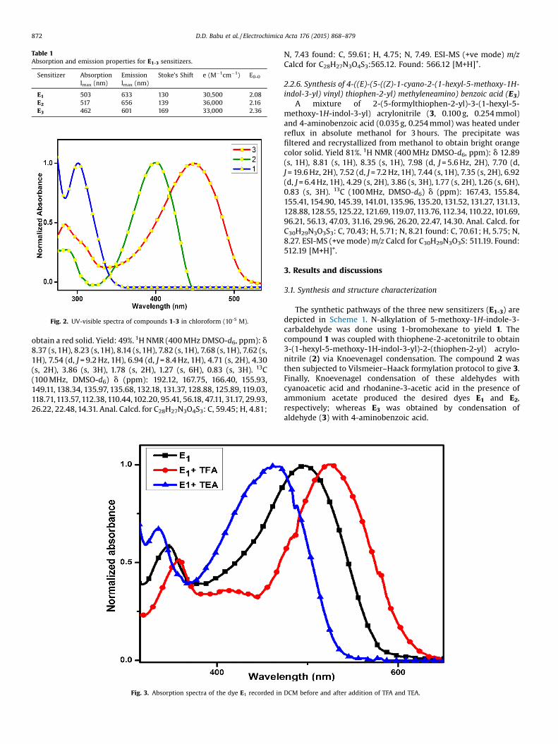
Table 1Absorption and emission properties for E1-3 sensitizers.
Sensitizer Absorptionlmax (nm)
Emissionlmax (nm)
Stoke’s Shift e (M�1cm�1) E0-0
E1 503 633 130 30,500 2.08E2 517 656 139 36,000 2.16E3 462 601 169 33,000 2.36
Fig. 2. UV-visible spectra of compounds 1-3 in chloroform (10-5 M).
872 D.D. Babu et al. / Electrochimica Acta 176 (2015) 868–879
obtain a red solid. Yield: 49%. 1H NMR (400 MHz DMSO-d6, ppm): d8.37 (s, 1H), 8.23 (s, 1H), 8.14 (s, 1H), 7.82 (s, 1H), 7.68 (s, 1H), 7.62 (s,1H), 7.54 (d, J = 9.2 Hz, 1H), 6.94 (d, J = 8.4 Hz, 1H), 4.71 (s, 2H), 4.30(s, 2H), 3.86 (s, 3H), 1.78 (s, 2H), 1.27 (s, 6H), 0.83 (s, 3H). 13C(100 MHz, DMSO-d6) d (ppm): 192.12, 167.75, 166.40, 155.93,149.11, 138.34, 135.97, 135.68, 132.18, 131.37, 128.88, 125.89, 119.03,118.71, 113.57, 112.38, 110.44, 102.20, 95.41, 56.18, 47.11, 31.17, 29.93,26.22, 22.48, 14.31. Anal. Calcd. for C28H27N3O4S3: C, 59.45; H, 4.81;
Fig. 3. Absorption spectra of the dye E1 recorded in
N, 7.43 found: C, 59.61; H, 4.75; N, 7.49. ESI-MS (+ve mode) m/zCalcd for C28H27N3O4S3:565.12. Found: 566.12 [M+H]+.
2.2.6. Synthesis of 4-((E)-(5-((Z)-1-cyano-2-(1-hexyl-5-methoxy-1H-indol-3-yl) vinyl) thiophen-2-yl) methyleneamino) benzoic acid (E3)
A mixture of 2-(5-formylthiophen-2-yl)-3-(1-hexyl-5-methoxy-1H-indol-3-yl) acrylonitrile (3, 0.100 g, 0.254 mmol)and 4-aminobenzoic acid (0.035 g, 0.254 mmol) was heated underreflux in absolute methanol for 3 hours. The precipitate wasfiltered and recrystallized from methanol to obtain bright orangecolor solid. Yield 81%. 1H NMR (400 MHz DMSO-d6, ppm): d 12.89(s, 1H), 8.81 (s, 1H), 8.35 (s, 1H), 7.98 (d, J = 5.6 Hz, 2H), 7.70 (d,J = 19.6 Hz, 2H), 7.52 (d, J = 7.2 Hz, 1H), 7.44 (s, 1H), 7.35 (s, 2H), 6.92(d, J = 6.4 Hz, 1H), 4.29 (s, 2H), 3.86 (s, 3H), 1.77 (s, 2H), 1.26 (s, 6H),0.83 (s, 3H). 13C (100 MHz, DMSO-d6) d (ppm): 167.43, 155.84,155.41, 154.90, 145.39, 141.01, 135.96, 135.20, 131.52, 131.27, 131.13,128.88, 128.55, 125.22, 121.69, 119.07, 113.76, 112.34, 110.22, 101.69,96.21, 56.13, 47.03, 31.16, 29.96, 26.20, 22.47, 14.30. Anal. Calcd. forC30H29N3O3S3: C, 70.43; H, 5.71; N, 8.21 found: C, 70.61; H, 5.75; N,8.27. ESI-MS (+ve mode) m/z Calcd for C30H29N3O3S: 511.19. Found:512.19 [M+H]+.
3. Results and discussions
3.1. Synthesis and structure characterization
The synthetic pathways of the three new sensitizers (E1-3) aredepicted in Scheme 1. N-alkylation of 5-methoxy-1H-indole-3-carbaldehyde was done using 1-bromohexane to yield 1. Thecompound 1 was coupled with thiophene-2-acetonitrile to obtain3-(1-hexyl-5-methoxy-1H-indol-3-yl)-2-(thiophen-2-yl) acrylo-nitrile (2) via Knoevenagel condensation. The compound 2 wasthen subjected to Vilsmeier–Haack formylation protocol to give 3.Finally, Knoevenagel condensation of these aldehydes withcyanoacetic acid and rhodanine-3-acetic acid in the presence ofammonium acetate produced the desired dyes E1 and E2,respectively; whereas E3 was obtained by condensation ofaldehyde (3) with 4-aminobenzoic acid.
DCM before and after addition of TFA and TEA.

Fig. 4. (a). Optimized structure and frontier molecular orbitals (HOMO and LUMO) of E1-3. (b). Simulated absorption spectra of E2. Spectrum is reported at the default standarddeviation value of 37.05 in TurbomoleX.
D.D. Babu et al. / Electrochimica Acta 176 (2015) 868–879 873
3.2. Photophysical properties
The absorption and emission spectra of the dyes (E1-3) recordedin chloroform (3�10-5M) solutions are displayed in Fig. 1(a) and(b), respectively; whereas, the pertinent results are summarized inTable 1. They exhibit two broad absorption peaks, the absorptionbands in the shorter wavelength region (<400 nm) can beattributed to the p-p* electronic excitations localized withinthe indole and p-bridge segments, whereas, the band in the longerwavelength region (462-517 nm) corresponds to the intramolecu-lar charge transfer (ICT) transition from indole (donor) to thecorresponding acceptor segment.
Usually, when organic dyes are adsorbed onto the TiO2 films,the absorption spectra may show blue-shift or red-shift ascompared to the spectra recorded in solutions state dependingon the interaction between the sensitizer and the semiconductorsurface. In fact, it is well known that, J-aggregation of the dye ontitanium dioxide surface leads to red shift, whereas, H-aggregationresults in blue shift of the absorption spectra. Fig. 1(c) depicts the
absorption spectra of the dye loaded onto the TiO2 films. Uponcomparing the aforementioned spectra with the absorptionspectra of the corresponding dyes in solution state, a clear redshift is observed in all the three sensitizers. This can be attributedto the J-aggregation occurred by an increased delocalization of thep* orbital of the conjugated system as a result of interactionbetween the carboxylate group of the corresponding sensitizer andTi4+ ions that directly lowers the energy of the p* level and therebyresults in broadening of the absorption spectra. Thus, introducingan indole unit and incorporating D–D–A–p–A architecture can bean efficient way to lower the aggregation tendency.
Further, the extent of charge transfer in these sensitizers isestablished by analyzing the absorption spectrum of the pre-cursors (Fig. 2). The absorption spectrum of compound 1 showslmax at 301 nm, which can be attributed to weak charge transferfrom indole to aldehyde group; on extending the conjugation byincorporation of cyanovinylene and thiophene units (2) causes anearly 100 nm red shift due to more effective delocalization of theelectron density on indole into the p-conjugation. Moreover, this

Fig. 5. Energy level diagram of E1-3 dyes.
874 D.D. Babu et al. / Electrochimica Acta 176 (2015) 868–879
progression of donor–acceptor interaction is also apparent oncomparing the absorption spectra of the aldehyde precursor 3 andthat of the sensitizers. This progressive bathochromic shift in theabsorption maxima exhibits the electron-withdrawing nature ofaldehyde and the respective acceptor units in E1-3.
Furthermore, the presence of acid-base equilibrium wasconfirmed by studying the change in absorption characteristicsof the sensitizers on addition of trifluoroacetic acid (TFA) ortriethylamine (TEA) to their chloroform solutions. A representativespectrum of E1 is shown in Fig. 3. It was observed that the additionof TEA to the dye solution resulted in blue shift of absorptionspectra. Whereas, TFA addition manifested a red shift. Thisobservation indicates that in the chloroform solution the dyepredominantly exists in the protonated form, but addition of TEAresults in the deprotonation of the dye (carboxylic acid segment)reducing the acceptor strength and thus weakening the donor-acceptor interactions. On the other hand, addition of TFA to the dyesolution will favor the amount of protonated form in the solutionand thereby reversing the equilibrium. Compared to E1 and E2,absorption changes on interaction with TFA/TEA were predomi-nant in E3 which illustrates stronger donor–acceptor interactionsin E3.
3.3. Theoretical calculations
All calculations were performed using Turbomole softwarepackage. The geometries were first optimized with semi empiricalAM1 basis with MOPAC in Tmolex. The aforementioned geometrieswere further optimized using C1 point group symmetry at densityfunctional theory level using the BP functional. The defaultconvergence criteria were used in all the geometry optimization.The resolution of the identity approximation and def-TZVPP basisset were used in all calculations. The optimized geometries as wellas the electronic distribution in HOMO-1, HOMO and LUMO aredisplayed in Fig. 4(a). The HOMO-1 is mainly localized onmethoxy-indole unit, whereas in HOMO a delocalization isobserved up to bridging thiophene unit. In the LUMO level a clearshift of electron density towards the acceptor segment is observed.This sort of charge separation between HOMO and LUMO is quitedesirable as it favors the effective electron migration from donor toacceptor segment of the dye and then to TiO2 conduction band. Thelow performance of sensitizer E2 could be explained by taking a
closer look at the electronic distribution in its LUMO level, thebreakage of conjugation impairs the efficient injection of electrondensity into the conduction band of TiO2. Another noteworthyoutcome from the DFT studies is that extent of the electronicoverlap between the HOMO and LUMO levels for E3 is less than thatof the other sensitizers (E1 and E2). This leads to a favorable chargeseparation and hence impending the electron–hole recombinationin E3 and thereby resulting in a much better overall efficiency [25].
Furthermore, time-dependent density functional theory(TDDFT) calculations were performed to predict spectroscopicproperties of the chromophores. TDDFT offers a computationallyinexpensive and reliable tool to comprehend the electronicexcitations of sensitizers in the presence of time-dependentperturbations. The simulated absorption spectra of E2 obtained atthe BP86 functional and def-TZVPP basis set are shown in Fig. 4(b).The theoretically obtained spectrum depicts only one band. Weobserved that on rescaling the standard deviation value (as givenby the TurbomoleX) of 37.05 to 9 leads to an overall refinement ofspectrum. The aforementioned spectrum (SI Fig. 5S) clearly depictstwo distinct bands and is well in agreement with experimentalspectrum. The band at higher energy can be attributed to p-p*transition, whereas the band at lower energy may be assigned tothe charge transfer from the donor to the acceptor segment. Hence,the theoretically obtained UV spectrum is well in agreement withthe experimentally obtained one.
3.4. Electrochemical Measurements
Cyclic voltammetry (CV) was used to obtain ground stateoxidation potential (GSOP) of the newly synthesized dyes insolution state. Cyclic voltammograms were used to calculate theoxidation onset (GSOP). Additionally, E0-0 was calculated fromabsorption and corrected emission spectra of the compounds. E0-0and GSOP values were used to calculate the excited state oxidationpotential (ESOP); the values in volts (V) against NHE wereconverted to electron volt (eV) according to Equation 1.
ESOP = [(GSOP (V)+4.7) � E0-0] eV (1)
The energy level diagram (Fig. 5) depicts the GSOP and ESOP ofE1-3 dyes. GSOP potential of E3 (�5.84 eV), E2 (�5.85 eV) and E1
(�5.87 eV) are lower in energy than that of I3�/I� redox system(�5.2 eV) [26], thus providing ample driving force for effective dye
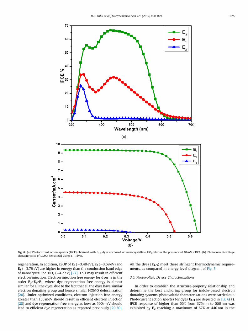
Fig. 6. (a). Photocurrent action spectra (IPCE) obtained with E1-3 dyes anchored on nanocrystalline TiO2 film in the presence of 10 mM CDCA. (b). Photocurrent-voltagecharacteristics of DSSCs sensitized using E1-3 dyes.
D.D. Babu et al. / Electrochimica Acta 176 (2015) 868–879 875
regeneration. In addition, ESOP of E3 (�3.48 eV), E2 (�3.69 eV) andE1 (�3.79 eV) are higher in energy than the conduction band edgeof nanocrystalline TiO2 (�4.2 eV) [27]. This may result in efficientelectron injection. Electron injection free energy for dyes is in theorder E3>E2>E1, where dye regeneration free energy is almostsimilar for all the dyes, due to the fact that all the dyes have similarelectron donating group and hence similar HOMO delocalization[20]. Under optimized conditions, electron injection free energygreater than 150 meV should result in efficient electron injection[28] and dye regeneration free energy as lows as 500 meV shouldlead to efficient dye regeneration as reported previously [29,30].
All the dyes (E1-3) meet these stringent thermodynamic require-ments, as compared in energy level diagram of Fig. 5.
3.5. Photovoltaic Device Characterizations
In order to establish the structure-property relationship anddetermine the best anchoring group for indole-based electrondonating systems, photovoltaic characterizations were carried out.Photocurrent action spectra for dyes E1-3 are depicted in Fig. 6(a).IPCE response of higher than 55% from 375 nm to 550 nm wasexhibited by E3 reaching a maximum of 67% at 440 nm in the

Fig. 7. EIS Nyquist plots for DSSCs sensitized using (a) E3 and (b) E2 and E1 dyes. (c).EIS Bode plots for DSSCs sensitized with E3,E2 and E1 dyes.
876 D.D. Babu et al. / Electrochimica Acta 176 (2015) 868–879
presence of 10 mM CDCA, whereas E1 and E2 showed compara-tively lower IPCE response. It was found that these dyes result inbest IPCE response in the presence of 10 mM CDCA, whereascomparative results in the presence of 1 Mm and 20 mM are givenin supplemental information (SI) Fig. 5S. CDCA was added as a co-adsorber to the dye solution to act as anti-aggregation reagent [31].The added co-adsorbers have shown to assist in favorable packing
Table 2shows the photovoltaic parameters of E1-3 sensitizers.
Sensitizer CDCA(mM)
Adsorption solvent
E1 10 ACN:Tert. Butanol (1:1)
E2 10 ACN:Tert. Butanol (1:1)
E3 10 ACN:Tert. Butanol (1:1)
E3 20 ACN:Tert. Butanol (1:1)
of the dye by covering the spaces between dye molecules. It hasbeen also reported that co-adsorbers decrease the dye loading upto 60% [32], which can significantly lower the photocurrentdensity. Such a decrease in dye loading in the presence of CDCA(20 mM) was observed for E1-3 dyes (Fig. 5S). However, in thepresence of 1 mM CDCA surface passivation was not optimum ascan be incurred from IPCE response of solar devices as given in SIFig. 5S.
Fig. 6(b) shows the I-V characteristics of the solar deviceprepared from dyes E1-3. It was observed that better IPCE responseof E3 translated into higher Jsc of 9.35 mA cm�2 compared to4.5 mA cm�2 of E1 and 0.28 mA cm�2 of E2 in the presence of 10 mMCDCA. Graphs showing comparison of I-V characteristics of thesolar devices in the presence of 1 and 20 mM CDCA, are shown in SIFig. 6S. Higher Jsc of E3 can be attributed to higher free energy ofelectron injection in TiO2 conduction band compared to E2 and E1
(Fig. 5, energy level diagram). Solar cells employing E3, E2 and E1
dyes yielded power conversion efficiency (%h) of 4.12 (Voc = 0.62 Vand FF = 0.71), (%h) of 0.05 (Voc = 0.3 V and FF = 0.53), (%h) of 1.48(Voc = 0.52 V and FF = 0.63), respectively compared to (%h) of 7.64 forN719 (Jsc = 15.9 mA cm�2, Voc = 0.73 and FF = 0.66). Table S1 in SIcontains complete photovoltaic results of E1-3 dyes in the presenceof different amounts of CDCA. Sensitizer E3 outperformed E1 and E2
dyes in overall solar cell performance. The better efficiency of E3
can be attributed to efficient electron withdrawing and injectioninto conduction band of TiO2 thus leading to efficient chargegeneration, transport and injection.
The clear separation of the electronic overlap as found bymodelling studies (Fig. 4(a)) between the HOMO and LUMO levelsfor E3 compared to the other sensitizers (E1 and E2) leads to afavorable charge separation and thereby hindering for electron–hole recombination in E3; this could explain the superior overallefficiency. Thus, the theoretical predictions are in accordance withthe experimentally obtained results. To further probe the interfacecharacteristics, impedance measurements were performed.
3.6. Electrochemical Impedance spectroscopy characterization
Electrochemical Impedance spectroscopy characterization (EIS)successfully models the charge transfer and chemical capacitanceat the interface of TiO2/dye/electrolyte and Pt/eletrolyte in DSSCunder operational conditions [33–35]. Typical EIS measurementsresult in Nyquist and Bode plots. In Nyquist plot, intermediatefrequecny semicirlce is related to electron transport throughmesoporous TiO2 and back electron transfer from TiO2 toelectrolyte. Bigger the radius of middle semicircle higher is thecharge recombination resistance (Rct) from TiO2 to electrolyte[35–37] corresponding to Nernst impedance, whereas radius ofsame semicircle indicates resistance to charge diffusion (Rd) underGerischer impedance as discussed by Grätzel at el [34]. In EISNyquist plots (Fig. 7(a) and (b)), for the best performing sensitizerE3, semicircles of similar size were observed in the presence ofdifferent concentrations of CDCA depicting low to minimum effectof CDCA on recombinaiton resistance (Rct). However, Nyquist plotsemicircles for E2 based solar devices were the biggest in radiusfollowed by E1 based solar devices. For the same sensitizer, e.g. E2
Jsc(mA cm�2) Voc (V) FF (%) h (%)
4.5 0.52 63 1.480.28 0.3 53 0.0469.35 0.62 71 4.128.3 0.64 72 3.82

Fig. 8. (a). FT-IR of E3 on TiO2 (b). Theoretically obtained FT-IR of E3.
D.D. Babu et al. / Electrochimica Acta 176 (2015) 868–879 877
radius of semicircle increased with the concentration of CDCA, dueto enhanced diffusion resistance (Rd). The difference in theimpedance behavior of E3 versus E2 and E1 is due to the natureof impedance involved, which can be predicted as Nernst for E3 andGerischer for E2 and E1. The nature of the impedance for E2 and E1
based solar devices can be attributed to Gerischer impedance,where Rd>>Rct, such a condition is valid for solar devices withsubstantial charge generation and diffusion related losses [34,38]as seen from photovoltaic results (Table 2).
In Bode frequecy plots (Fig. 7(c)), lifetime for injected electronsinto TiO2 conduction band can be estimated by using the relation(tCB = 1/2pf), where t is the lifetime of electrons in TiO2 and f is themid frequency peak in Bode plots. The mid frequency peaks of thebode plots obtained for the DSSCs based on E3, E2, E1 and N719were at 7 Hz, 11 Hz, 35 Hz and 29 Hz, respectively. The
corresponding to eTiO2 of E3, E2, E1 and N719 are 23, 14.5,4.5 and 5.5 ms, respectively. Though generally higher eTiO2 isrelated with improved Voc, however that seems plausible for E3 andN719 dyes whereas the complex nature of E1 and E2 results cannotbe explained based on these findings only since impedance forthese two systems is much higher due to reasons discussed forNyquist plot.
3.7. FT-IR analysis: Anchoring studies of the Dyes on TiO2
FTIR spectroscopy is widely applied in order to gain an insightinto the nature of anchoring groups and the mode of theirinteraction with the TiO2 substrate. By implementing thistechnique one can elucidate the absorption states of the sensitizersand/or bonds formed upon adsorption on the TiO2 nanoparticles

878 D.D. Babu et al. / Electrochimica Acta 176 (2015) 868–879
using a set of rules developed by Deacon and Phillips [39].According to this rule, there is a direct correlation between thedifference (Dn) between symmetric and asymmetric bondstretching frequencies of a carbonyl group of carboxylic acid andits corresponding coordination type. Three possible scenariosexist; if (Dn) of the dye adsorbed onto TiO2 (Dnabs) is smaller thanthat of the free molecule (Dnfree), i.e (Dnabs) < (Dnfree), thebidentate adsorption mode will be present; if (Dnabs) � (Dnfree), inall probability the chelating mode is present. Whereas, if (Dnabs) >(Dnfree), the dye molecule takes a monodentate binding mode [39].Against this background, the infrared absorption spectra weremeasured for each of the dyes and the corresponding sensitizedTiO2 films. FT-IR spectrum of the solid E3 dye (Fig. 8(a)) showsprominent bands at 1687 cm�1 and 2220 cm�1 corresponding tothe >C=O and -CRN stretching, respectively. The FTIR spectrum ofthe E3 anchored on TiO2 film clearly depicts bands at 1570 and1400 cm�1 for the asymmetric and symmetric stretching modes ofthe >C=O group, indicating that the carboxylic acid group isdeprotonated and is involved in the adsorption of the sensitizer onTiO2. Further, the disappearance of nC=O and the appearance of newpeaks of symmetric and asymmetric stretching reveal that the dyeis chemisorbed, thereby ruling out physisorption.
Further, from vibrational frequency analysis, the nature of thebinding mode can be elucidated by implementing Deacon andPhillips rule. From data it can be inferred that the dye is anchoredon titanium dioxide through the carboxylate group by means of abidentate chelation or a bridging of surface titanium ions ratherthan an ester type linkage. Similar trend was observed in the othertwo sensitizers (E1 and E2) as well. Furthermore, in the all the threedyes the CRN band frequency remains unchanged, demonstratingthat the cyano group is not involved in dye-adsorption process.Another peculiar feature observed in all the FT-IR spectra is thepresence of a broad absorption band around 3400 cm�1, whichmight be attributed to absorption of moisture from the dyesolution, as the TiO2 film was heated prior to staining. Furthermore,we calculated the infrared absorption spectra of all the sensitizersusing Turbomole software package and compared the aforemen-tioned spectra with the experimentally obtained ones. Fig. 8 (b)depicts the theoretically obtained FT-IR spectrum of E3. It isevident that the theoretically obtained spectrum is well inagreement with the experimentally acquired one.
4. Conclusions
We have successfully designed and synthesized three newsensitizers (E1-3) having D-D–A–p-A architecture, whereinmethoxy group acts as an auxiliary donor to the principal donor,i.e. indole moiety, cynovinylene performs as an auxiliary acceptor,thiophene takes on the role of p-conjugation bridge and varyinggroups (2-cyanoacrylic acid, rhodanine-3-acetic acid and 4-aminobenzoic acid) function as principal acceptor units. Theeffective conjugation in the new sensitizers leads to a broadabsorption spectrum and a high molar extinction coefficient of thecorresponding dyes which in turn facilitates the dyes to harvestmore photoelectrons. The DSSC fabricated using E3 showed thehighest JSC (9.35 mA cm�2), which is consistent with the fact thatsensitizer E3 has the widest IPCE response among the threesensitizers. Furthermore, the higher efficiency of E3 can also beattributed to its longer electron lifetime (eTiO2) and high lyingLUMO which enhances the thermodynamic feasibility of electroninjection into the conduction band of TiO2. The DFT studies reveal abetter charge separation between the HOMO and LUMO levels ofthe E3 sensitizer. The large difference in efficiency between E3 andthe other two sensitizers indicates that the acceptor/anchoringsegment should be screened with caution as they are instrumentalin governing the overall efficiency.
Acknowledgements
The authors are thankful to NITK, Surathkal, India, for providingnecessary laboratory facilities. DDB and AVA are grateful to Prof.Yiying Wu, Professor, Department of Chemistry and Biochemistry,Ohio State University for eloquent suggestions. The authors arealso thankful to the Department of Textile Engineering, Chemistryand Science at North Carolina State University for the financialsupport.
Appendix A. Supplementary data
Supplementary data associated with this article can be found, inthe online version, at http://dx.doi.org/10.1016/j.electacta.2015.07.079.
References
[1] B. O’Regan, M. Grätzel, Nature 353 (1991) 737–740.[2] M.K. Nazeeruddin, A. Kay, I. Rodicio, R. Humphry-Baker, E. Mueller, P. Liska, N.
Vlachopoulos, M. Graetzel, J. Am. Chem. Soc. 115 (1993) 6382–6390.[3] M.K. Nazeeruddin, R. Humphry-Baker, P. Liska, M. Grätzel, J.B. Phys. Chem, 07
(2003) 8981–8987.[4] Z. Ning, H. Tian, Chem. Commun. (2009) 5483–5495.[5] J. Shi, J. Chen, Z. Chai, H. Wang, R. Tang, K. Fan, M. Wu, H. Han, J. Qin, T. Peng, Q.
Li, Z. Li, J. Mater. Chem. 22 (2012) 18830–18838.[6] J. He, F. Guo, X. Li, W. Wu, J. Yang, J. Hua, Chem. Eur. J. 18 (2012) 7903–7915.[7] C.-J. Yang, Y.J. Chang, M. Watanabe, Y.-S. Hon, T.J. Chow, J. Mater. Chem. 22
(2012) 4040–4049.[8] D.P. Hagberg, J.-H. Yum, H. Lee, F. De Angelis, T. Marinado, K.M. Karlsson, R.
Humphry-Baker, L. Sun, A. Hagfeldt, M. Grätzel, M.K. Nazeeruddin, J. Am.Chem. Soc. 130 (2008) 6259–6266.
[9] W.-L. Ding, D.-M. Wang, Z.-Y. Geng, X.-L. Zhao, W.-B. Xu, Dyes and Pigments 98(2013) 125–135.
[10] E.M. Barea, C. Zafer, B. Gultekin, B. Aydin, S. Koyuncu, S. Icli, F.F. Santiago, J.Bisquert, J. Phys. Chem. C 114 (2010) 19840–19848.
[11] A.S. Hart, C.B. K.C, N.K. Subbaiyan, P.A. Karr, F. D’Souza, ACS Appl. Mater.Interfaces 4 (2012) 5813–5820.
[12] Y. Bai, J. Zhang, D. Zhou, Y. Wang, M. Zhang, P. Wang, J. Am. Chem. Soc. 133(2011) 11442–11445.
[13] K.M. Karlsson, X. Jiang, S.K. Eriksson, E. Gabrielsson, H. Rensmo, A. Hagfeldt, L.Sun, Chem. Eur. J. 17 (2011) 6415–6424.
[14] S. Higashijima, Y. Inoue, H. Miura, Y. Kubota, K. Funabiki, T. Yoshida, M. Matsui,RSC Adv. 2 (2012) 2721–2724.
[15] S. Qu, B. Wang, F. Guo, J. Li, W. Wu, C. Kong, Y. Long, J. Hua, Dyes and Pigments92 (2012) 1384–1393.
[16] J. Mao, F. Guo, W. Ying, W. Wu, J. Li, J. Hua, Chem. Asian J. 7 (2012) 982–991.[17] S.-T. Huang, Y.-C. Hsu, Y.-S. Yen, H.H. Chou, J.T. Lin, C.-W. Chang, C.-P. Hsu, C.
Tsai, D.-J. Yin, J. Phys. Chem. C 112 (2008) 19739–19747.[18] J.T. Lin, P.-C. Chen, Y.-S. Yen, Y.-C. Hsu, H.-H. Chou, M.-C.P. Yeh, Org. Lett. 11
(2009) 97–100.[19] A. Mishra, M.K.R. Fische, P. Bäuerle, Angewandte Chemie International Edition
48 (2009) 2474–2499.[20] D.D. Babu, S.R. Gachumale, S. Anandan, A.V. Adhikari, Dyes and Pigments 112
(2015) 183–191.[21] L. Li, S. Chen, C. Xu, Y. Zhao, N.G. Rudawski, K.J. Ziegler, ACS Applied Materials &
Interfaces 6 (2014) 20978–20984.[22] L. Li, C. Xu, Y. Zhao, S. Chen, K.J. Ziegler, ACS Applied Materials & Interfaces 7
(2015) 12824–12831.[23] N. Koumura, Z.-S. Wang, S. Mori, M. Miyashita, E. Suzuki, K. Hara, J. Am. Chem.
Soc. 128 (2006) 14256–14257.[24] M. Zhang, J. Liu, Y. Wang, D. Zhou, P. Wang, Chem. Sci. 2 (2011) 1401–1406.[25] A. Baheti, K.R.J. Thomas, C.-P. Lee, C.-T. Li, K.-C. Ho, J. Mater. Chem. A 2 (2014)
5766–5779.[26] P. Qu, G.J. Meyer, Langmuir 17 (2001) 6720–6728.[27] G. Oskam, B.V. Bergeron, G.J. Meyer, P.C. Searson, J. Phys. Chem. B 105 (2001)
6867–6873.[28] S.E. Koops, B.C. O’Regan, P.R.F. Barnes, J.R. Durrant, J. Am. Chem. Soc. 131 (2009)
4808–4818.[29] B.E. Hardin, H.J. Snaith, M.D. McGehee, Nat Photon 6 (2012) 162–169.[30] M. Hussain, A. Islam, I. Bedja, R.K. Gupta, L. Han, A. El-Shafei, Phys. Chem.
Chem. Phys. 16 (2014) 14874–14881.[31] S. Ito, H. Miura, S. Uchida, M. Takata, K. Sumioka, P. Liska, P. Comte, P. Péchy, M.
Grätzel, Chem. Commun. (2008) 5194–5196.[32] N.R. Neale, N. Kopidakis, J. van de Lagemaat, M. Grätzel, A.J. Frank, J. Phys.
Chem. B 109 (2005) 23183–23189.[33] R. Kern, R. Sastrawan, J. Ferber, R. Stangl, J. Luther, Electrochimica Acta 47
(2002) 4213–4225.[34] Q. Wang, J.-E. Moser, M. Grätzel, J. Phys. Chem. B 109 (2005) 14945–14953.

D.D. Babu et al. / Electrochimica Acta 176 (2015) 868–879 879
[35] N. Koide, A. Islam, Y. Chiba, L. Han, Journal of Photochemistry and PhotobiologyA: Chemistry 182 (2006) 296–305.
[36] L. Han, N. Koide, Y. Chiba, A. Islam, T. Mitate, Comptes Rendus Chimie 9 (2006)645–651.
[37] H. Cheema, A. Islam, R. Younts, B. Gautam, I. Bedja, R.K. Gupta, L. Han, K.Gundogdu, A. El-Shafei, Phys. Chem. Chem. Phys. 16 (2014) 27078–27087.
[38] J. Bisquert, J. Phys. Chem. B 106 (2001) 325–333.[39] G.B. Deacon, R.J. Phillips, Chemical Review 33 (1980) 227–250.
Copyright © 2022 FDOKUMEN