Dye-sensitized solar tubes: A new solar cell design for efficient current collection and improved...
6
Dye-sensitized solar tubes: A new solar cell design for efficient current collection and improved cell sealing Zion Tachan, Sven R ¨ uhle , Arie Zaban Institute of Nanotechnology & Advanced Materials, Department of Chemistry, Bar Ilan University, Ramat Gan 52900, Israel article info Article history: Received 13 May 2009 Received in revised form 5 October 2009 Accepted 5 October 2009 Available online 1 November 2009 Keywords: Dye-sensitized solar cells Dye-sensitized solar tubes FTO synthesis Spray pyrolysis Current collector Sealing abstract A dye-sensitized solar cell (DSSC) fabricated inside a glass tube to form a dye-sensitized solar tube (DSST) is presented. We developed the synthesis of Fluorine-doped Tin oxide (FTO) with a high optical transmittance and low sheet resistance, which was deposited inside a glass tube by spray pyrolysis. The FTO was covered with a mesoporous TiO 2 film using electrophoretic deposition (EPD). Subsequently the tube was sintered, sensitized with a Ru-dye (N3) and immersed into redox electrolyte while a Pt-coated rod closed the electrical circuit. Sealing of DSSCs is still a major problem. The new design reduces significantly the area that requires sealing compared to conventional flat cells, moreover sealing of a tube is significantly simpler than two flat plates. A huge advantage of the tube design is the possibility to incorporate a current collector without blocking direct sunlight from entering the cell. Panels consisting of DSSTs allow air flow in between the tubes, thus decreasing the wind resistivity while the cylindrical shape of the DSST can be used to collect diffuse light more effectively. Initial results on a prototype show a light to electric power conversion efficiency of 2.8%, demonstrating the feasibility of the new tube concept. & 2009 Elsevier B.V. All rights reserved. 1. Introduction Dye-sensitized solar cells (DSSC) based on nanocrystalline mesoporous TiO 2 films have attracted much attention as a potential low-cost alternative for single- or polycrystalline p–n junction silicon solar cells. DSSCs can reach solar to electrical energy conversion efficiencies above 10% [1]. Upon illumination photons are absorbed by dye molecules, which inject electrons from their excited states into the conduction band of the TiO 2 nano-particles. Oxidized dye molecules are recharged by a redox electrolyte, which transports the positive charges by diffusion to a Pt counter electrode, while electrons diffuse through the TiO 2 network to a transparent conducting front electrode. The low- absorption coefficient of a dye monolayer is compensated by the mesoporous structure of the TiO 2 film, which leads to a strong increase in the number of TiO 2 /dye/electrolyte interfaces through which photons pass, thus increasing the absorption probability. Best performance is usually achieved with the I À /I À 3 redox couple dissolved in organic solvent while Fluorine-doped SnO 2 (FTO) is a widely used transparent conducting front electrode material with exceptional chemical stability. Even though DSSCs are on the edge of commercialization a major challenge remains the sealing of the photo-electrochemical cell [2]. The high vapor pressure of the solvent and its capability to dissolve/destroy most sealing materials over time scales relevant for solar panels is a main obstacle for large-scale production. This problem has triggered the search for solid state or quasi solid state hole conductors, which can replace the liquid electrolyte without loss in performance. A number of materials such as inorganic wide bandgap hole conductors [3–6], hole conducting molecular solids [7], polymers [8], as well as ionic liquids [9–11] and gel-based electrolytes [12,13] have been investigated. However up to now it has not been possible to develop solid-state DSSCs with conver- sion efficiencies compatible with liquid electrolyte-based cells. Sealing remains a major challenge, especially in solar panels where individual cells are connected in series, which all have to be sealed separately. A further disadvantage of the flat solar cell design is a reduced conversion efficiency due to the presence of a non-transparent conducting grid on the electrode facing the incident light, which is required for photocurrent collection. Alternative cell geometries have been proposed [14–17], however most of them involve a more complex cell design, which complicates cell fabrication. Here we present a new and simple DSSC design based on tubes. Glass tubes were coated from the inner side with a conducting transparent FTO layer onto which the mesoporous TiO 2 film was deposited. A cross-section of these DSSTs is schematically shown in Fig. 1a. As counter electrodes we used FTO-coated glass rods, onto which a Pt layer was sputtered. The round shape of the DSSTs opened a way to transfer the opaque current collector to the backside of the cell, thus avoiding the losses associated with shading from collector lines (Fig. 1b). DSSTs drastically reduce the ARTICLE IN PRESS Contents lists available at ScienceDirect journal homepage: www.elsevier.com/locate/solmat Solar Energy Materials & Solar Cells 0927-0248/$ - see front matter & 2009 Elsevier B.V. All rights reserved. doi:10.1016/j.solmat.2009.10.006 Corresponding author. E-mail address: [email protected] (S. R ¨ uhle). Solar Energy Materials & Solar Cells 94 (2010) 317–322
Transcript of Dye-sensitized solar tubes: A new solar cell design for efficient current collection and improved...

ARTICLE IN PRESS
Solar Energy Materials & Solar Cells 94 (2010) 317–322
Contents lists available at ScienceDirect
Solar Energy Materials & Solar Cells
0927-02
doi:10.1
� Corr
E-m
journal homepage: www.elsevier.com/locate/solmat
Dye-sensitized solar tubes: A new solar cell design for efficient currentcollection and improved cell sealing
Zion Tachan, Sven Ruhle �, Arie Zaban
Institute of Nanotechnology & Advanced Materials, Department of Chemistry, Bar Ilan University, Ramat Gan 52900, Israel
a r t i c l e i n f o
Article history:
Received 13 May 2009
Received in revised form
5 October 2009
Accepted 5 October 2009Available online 1 November 2009
Keywords:
Dye-sensitized solar cells
Dye-sensitized solar tubes
FTO synthesis
Spray pyrolysis
Current collector
Sealing
48/$ - see front matter & 2009 Elsevier B.V. A
016/j.solmat.2009.10.006
esponding author.
ail address: [email protected] (S. Ruhle).
a b s t r a c t
A dye-sensitized solar cell (DSSC) fabricated inside a glass tube to form a dye-sensitized solar tube
(DSST) is presented. We developed the synthesis of Fluorine-doped Tin oxide (FTO) with a high optical
transmittance and low sheet resistance, which was deposited inside a glass tube by spray pyrolysis.
The FTO was covered with a mesoporous TiO2 film using electrophoretic deposition (EPD). Subsequently
the tube was sintered, sensitized with a Ru-dye (N3) and immersed into redox electrolyte while a
Pt-coated rod closed the electrical circuit. Sealing of DSSCs is still a major problem. The new design
reduces significantly the area that requires sealing compared to conventional flat cells, moreover sealing
of a tube is significantly simpler than two flat plates. A huge advantage of the tube design is the
possibility to incorporate a current collector without blocking direct sunlight from entering the cell.
Panels consisting of DSSTs allow air flow in between the tubes, thus decreasing the wind resistivity
while the cylindrical shape of the DSST can be used to collect diffuse light more effectively. Initial results
on a prototype show a light to electric power conversion efficiency of 2.8%, demonstrating the feasibility
of the new tube concept.
& 2009 Elsevier B.V. All rights reserved.
1. Introduction
Dye-sensitized solar cells (DSSC) based on nanocrystallinemesoporous TiO2 films have attracted much attention as apotential low-cost alternative for single- or polycrystalline p–njunction silicon solar cells. DSSCs can reach solar to electricalenergy conversion efficiencies above 10% [1]. Upon illuminationphotons are absorbed by dye molecules, which inject electronsfrom their excited states into the conduction band of the TiO2
nano-particles. Oxidized dye molecules are recharged by a redoxelectrolyte, which transports the positive charges by diffusion to aPt counter electrode, while electrons diffuse through the TiO2
network to a transparent conducting front electrode. The low-absorption coefficient of a dye monolayer is compensated by themesoporous structure of the TiO2 film, which leads to a strongincrease in the number of TiO2/dye/electrolyte interfaces throughwhich photons pass, thus increasing the absorption probability.Best performance is usually achieved with the I�/I�3 redox coupledissolved in organic solvent while Fluorine-doped SnO2 (FTO) is awidely used transparent conducting front electrode material withexceptional chemical stability.
Even though DSSCs are on the edge of commercialization amajor challenge remains the sealing of the photo-electrochemicalcell [2]. The high vapor pressure of the solvent and its capability to
ll rights reserved.
dissolve/destroy most sealing materials over time scales relevantfor solar panels is a main obstacle for large-scale production. Thisproblem has triggered the search for solid state or quasi solid statehole conductors, which can replace the liquid electrolyte withoutloss in performance. A number of materials such as inorganic widebandgap hole conductors [3–6], hole conducting molecular solids[7], polymers [8], as well as ionic liquids [9–11] and gel-basedelectrolytes [12,13] have been investigated. However up to now ithas not been possible to develop solid-state DSSCs with conver-sion efficiencies compatible with liquid electrolyte-based cells.Sealing remains a major challenge, especially in solar panelswhere individual cells are connected in series, which all have to besealed separately.
A further disadvantage of the flat solar cell design is a reducedconversion efficiency due to the presence of a non-transparentconducting grid on the electrode facing the incident light, which isrequired for photocurrent collection. Alternative cell geometrieshave been proposed [14–17], however most of them involve amore complex cell design, which complicates cell fabrication.
Here we present a new and simple DSSC design based on tubes.Glass tubes were coated from the inner side with a conductingtransparent FTO layer onto which the mesoporous TiO2 film wasdeposited. A cross-section of these DSSTs is schematically shownin Fig. 1a. As counter electrodes we used FTO-coated glass rods,onto which a Pt layer was sputtered. The round shape of the DSSTsopened a way to transfer the opaque current collector to thebackside of the cell, thus avoiding the losses associated withshading from collector lines (Fig. 1b). DSSTs drastically reduce the
ARTICLE IN PRESS
Fig. 1. (a) Schematic cross-section of a dye-sensitized solar tube (DSST) showing
the glass tube (1a), the FTO layer deposited by spray pyrolysis (2a), a highly
conducting current collector attached to the FTO on the bottom side inside the
DSST (3a) and a polymer layer, which is protecting the current collector (4a). The
mesoporous dye-sensitized TiO2 film (5a) deposited onto the FTO is immersed into
the redox electrolyte (6a). The circuit is closed by a counter electrode consisting of
a sputtered Pt layer (7a) on top of a sprayed FTO film (8a), deposited onto a quartz
rod (9a). (b) Schematic drawing of a conventional dye-sensitized solar cell (DSSC)
consisting of a flat glass substrate (1b), covered with commercial FTO (2b). The
opaque current collector (3b) with a protective coating (4b) is partially blocking
the incident light. The dye-sensitized TiO2 film (5b) is immersed into electrolyte
(6b) which is in contact with Pt (7b) deposited on flat FTO glass (8b).
Z. Tachan et al. / Solar Energy Materials & Solar Cells 94 (2010) 317–322318
area for sealing and can be used as building blocks for dye-sensitized solar panels in which individual cells (tubes) are easilymounted and replaced. We have produced a DSST andcharacterized a surface segment with an area of 0.7 cm2 underdirect illumination of simulated sunlight (AM1.5) to compare itsperformance to flat DSSCs.
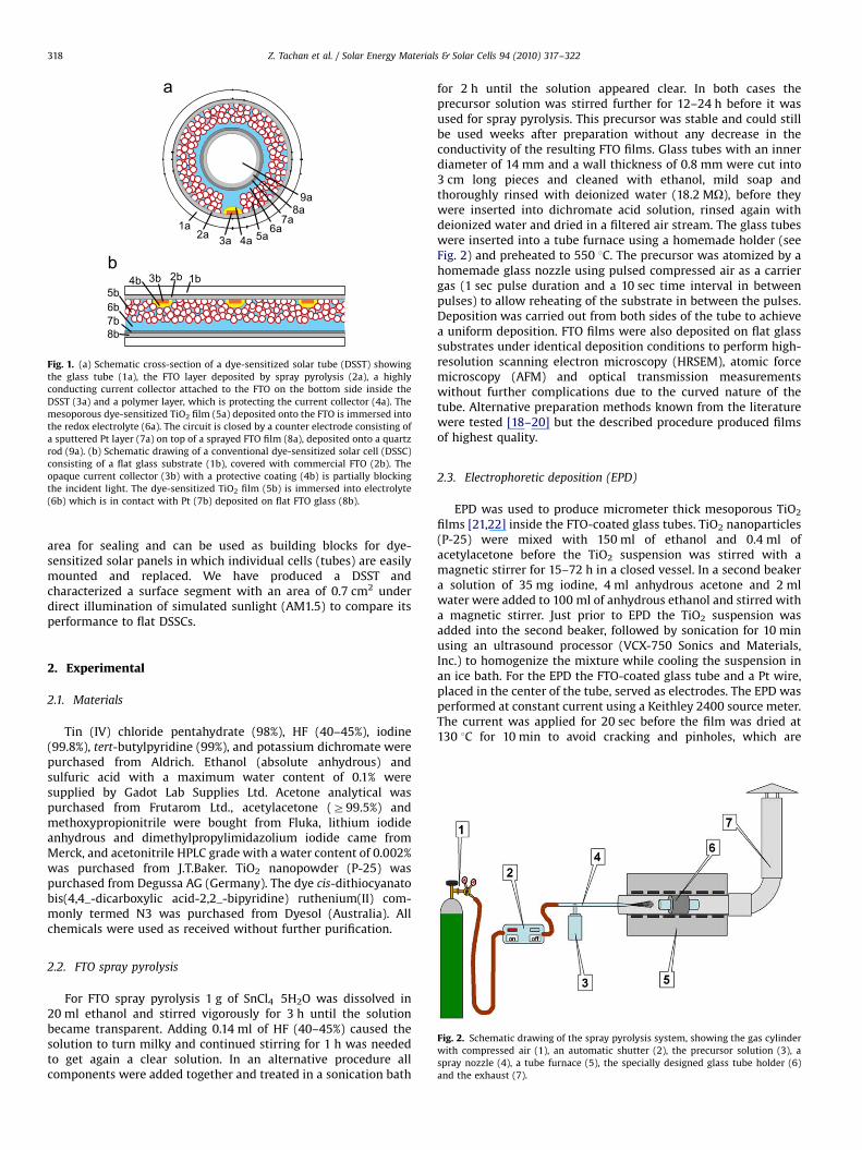
Fig. 2. Schematic drawing of the spray pyrolysis system, showing the gas cylinder
with compressed air (1), an automatic shutter (2), the precursor solution (3), a
spray nozzle (4), a tube furnace (5), the specially designed glass tube holder (6)
and the exhaust (7).
2. Experimental
2.1. Materials
Tin (IV) chloride pentahydrate (98%), HF (40–45%), iodine(99.8%), tert-butylpyridine (99%), and potassium dichromate werepurchased from Aldrich. Ethanol (absolute anhydrous) andsulfuric acid with a maximum water content of 0.1% weresupplied by Gadot Lab Supplies Ltd. Acetone analytical waspurchased from Frutarom Ltd., acetylacetone (Z99.5%) andmethoxypropionitrile were bought from Fluka, lithium iodideanhydrous and dimethylpropylimidazolium iodide came fromMerck, and acetonitrile HPLC grade with a water content of 0.002%was purchased from J.T.Baker. TiO2 nanopowder (P-25) waspurchased from Degussa AG (Germany). The dye cis-dithiocyanatobis(4,4_-dicarboxylic acid-2,2_-bipyridine) ruthenium(II) com-monly termed N3 was purchased from Dyesol (Australia). Allchemicals were used as received without further purification.
2.2. FTO spray pyrolysis
For FTO spray pyrolysis 1 g of SnCl4 �5H2O was dissolved in20 ml ethanol and stirred vigorously for 3 h until the solutionbecame transparent. Adding 0.14 ml of HF (40–45%) caused thesolution to turn milky and continued stirring for 1 h was neededto get again a clear solution. In an alternative procedure allcomponents were added together and treated in a sonication bath
for 2 h until the solution appeared clear. In both cases theprecursor solution was stirred further for 12–24 h before it wasused for spray pyrolysis. This precursor was stable and could stillbe used weeks after preparation without any decrease in theconductivity of the resulting FTO films. Glass tubes with an innerdiameter of 14 mm and a wall thickness of 0.8 mm were cut into3 cm long pieces and cleaned with ethanol, mild soap andthoroughly rinsed with deionized water (18.2 MO), before theywere inserted into dichromate acid solution, rinsed again withdeionized water and dried in a filtered air stream. The glass tubeswere inserted into a tube furnace using a homemade holder (seeFig. 2) and preheated to 550 1C. The precursor was atomized by ahomemade glass nozzle using pulsed compressed air as a carriergas (1 sec pulse duration and a 10 sec time interval in betweenpulses) to allow reheating of the substrate in between the pulses.Deposition was carried out from both sides of the tube to achievea uniform deposition. FTO films were also deposited on flat glasssubstrates under identical deposition conditions to perform high-resolution scanning electron microscopy (HRSEM), atomic forcemicroscopy (AFM) and optical transmission measurementswithout further complications due to the curved nature of thetube. Alternative preparation methods known from the literaturewere tested [18–20] but the described procedure produced filmsof highest quality.
2.3. Electrophoretic deposition (EPD)
EPD was used to produce micrometer thick mesoporous TiO2
films [21,22] inside the FTO-coated glass tubes. TiO2 nanoparticles(P-25) were mixed with 150 ml of ethanol and 0.4 ml ofacetylacetone before the TiO2 suspension was stirred with amagnetic stirrer for 15–72 h in a closed vessel. In a second beakera solution of 35 mg iodine, 4 ml anhydrous acetone and 2 mlwater were added to 100 ml of anhydrous ethanol and stirred witha magnetic stirrer. Just prior to EPD the TiO2 suspension wasadded into the second beaker, followed by sonication for 10 minusing an ultrasound processor (VCX-750 Sonics and Materials,Inc.) to homogenize the mixture while cooling the suspension inan ice bath. For the EPD the FTO-coated glass tube and a Pt wire,placed in the center of the tube, served as electrodes. The EPD wasperformed at constant current using a Keithley 2400 source meter.The current was applied for 20 sec before the film was dried at130 1C for 10 min to avoid cracking and pinholes, which are

ARTICLE IN PRESS
Z. Tachan et al. / Solar Energy Materials & Solar Cells 94 (2010) 317–322 319
caused by organic residues. After applying the deposition cycle sixtimes a surface area of approximately 6 cm2 was homogeneouslycovered with a mesoporous TiO2 film. To characterize the solarcell performance of a tube segment the film area was reduced toapproximately 1 cm2 and the excessive TiO2 film was mechani-cally scraped off. After sintering for 1 h at 550 1C the porous TiO2
tube electrodes cooled down to 80 1C and were immersedovernight into a 0.5 mM solution of N3 dye in ethanol.
2.4. Characterization methods
The morphology of the FTO films was investigated using aHRSEM (JEOL, 7000F) and an AFM (Multi-Mode V, Vecco). X-raydiffraction was performed using a Bruker D8 X-ray diffractometerwith Cu Ka radiation (l=1.5406 A). Transmittance measurementswere carried out in a Cary 500 scan UV–vis–NIR spectrophot-ometer (Varian, USA). The mesoporous TiO2 film thickness wasmeasured with a profilometer (Surftest SV 500). For solar cellmeasurements the dye-covered electrodes were rinsed withethanol and dried under a filtered air stream. Afterwards a5-mm-thin stripe of copper foil was attached to the FTO film atthe bottom inside the glass tube to serve as a current collector,which was covered with Surlyn (DuPont) to protect it from thecorrosive redox electrolyte and to prevent direct contact withthe counter electrode. A special designed cell holder with anaperture area of 0.7 cm2 was used to measure the performance ofthe mesoporous dye-sensitized TiO2 film inside the tube. As a
Fig. 3. (a) HRSEM image of an FTO film sprayed on a glass substrate at temperature
of 550 1C. (b) Cross section HRSEM image showing an FTO film thickness of around
500 nm.
counter electrode a quartz rod was used, coated with Pt on top ofan FTO layer. The composition of the electrolyte was: 0.6 Mdimethylpropylimidazolium iodide, 0.1 M LiI, 0.05 M I2, 0.5 Mtert-butylpyridine in 1:1 acetonitrile–methoxypropionitrile. I–V
characteristics were recorded with a potentiostat (Eco-Chemie)while the solar tube was illuminated in a Newport solar simulator(class A).
3. Results and discussion
3.1. FTO characterization
A HRSEM image of a sprayed FTO film with a sheet resistanceof 10 O/square is shown in Fig. 3a (deposited at 550 1C onto a flatglass substrate). From the cross-section image, shown in Fig. 3b,we determine a film thickness of around 500 nm. An AFM imageof sprayed FTO, scanned over an area of 5 mm�5 mm is shown inFig. 4, from which a surface roughness (Ra) of 13.7 nm isdetermined. The peaks in the XRD spectrum presented in Fig. 5are typical for the tetragonal structure of SnO2 [23,24]. Moreoverwe observe a high intensity of the (2 0 0) reflection, indicating apreferential growth direction [25]. Optical transmission spectra ofbare and FTO-covered glass substrates are shown in Fig. 6. In thewavelength range 400–800 nm the spray-deposited FTO shows atransmittance of around 80%. Local maxima at 385, 455, 580 and770 nm are caused by multiple reflections at the FTO/glass andFTO/air interface [26].
Fig. 4. AFM topography image of the spray pyrolysis deposited FTO film.
Fig. 5. XRD pattern of a spray pyrolysis-deposited FTO layer on glass.
ARTICLE IN PRESS
Z. Tachan et al. / Solar Energy Materials & Solar Cells 94 (2010) 317–322320
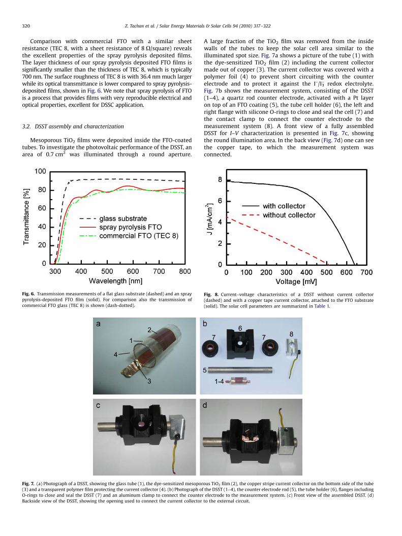
Comparison with commercial FTO with a similar sheetresistance (TEC 8, with a sheet resistance of 8 O/square) revealsthe excellent properties of the spray pyrolysis deposited films.The layer thickness of our spray pyrolysis deposited FTO films issignificantly smaller than the thickness of TEC 8, which is typically700 nm. The surface roughness of TEC 8 is with 36.4 nm much largerwhile its optical transmittance is lower compared to spray pyrolysis-deposited films, shown in Fig. 6. We note that spray pyrolysis of FTOis a process that provides films with very reproducible electrical andoptical properties, excellent for DSSC application.
3.2. DSST assembly and characterization
Mesoporous TiO2 films were deposited inside the FTO-coatedtubes. To investigate the photovoltaic performance of the DSST, anarea of 0.7 cm2 was illuminated through a round aperture.
Fig. 6. Transmission measurements of a flat glass substrate (dashed) and an spray
pyrolysis-deposited FTO film (solid). For comparison also the transmission of
commercial FTO glass (TEC 8) is shown (dash-dotted).
Fig. 7. (a) Photograph of a DSST, showing the glass tube (1), the dye-sensitized mesopor
(3) and a transparent polymer film protecting the current collector (4). (b) Photograph of
O-rings to close and seal the DSST (7) and an aluminum clamp to connect the counter
Backside view of the DSST, showing the opening used to connect the current collector
A large fraction of the TiO2 film was removed from the insidewalls of the tubes to keep the solar cell area similar to theilluminated spot size. Fig. 7a shows a picture of the tube (1) withthe dye-sensitized TiO2 film (2) including the current collectormade out of copper (3). The current collector was covered with apolymer foil (4) to prevent short circuiting with the counterelectrode and to protect it against the I–/I3
– redox electrolyte.Fig. 7b shows the measurement system, consisting of the DSST(1–4), a quartz rod counter electrode, activated with a Pt layeron top of an FTO coating (5), the tube cell holder (6), the left andright flange with silicone O-rings to close and seal the cell (7) andthe contact clamp to connect the counter electrode to themeasurement system (8). A front view of a fully assembledDSST for I–V characterization is presented in Fig. 7c, showingthe round illumination area. In the back view (Fig. 7d) one can seethe copper tape, to which the measurement system wasconnected.
ous TiO2 film (2), the copper stripe current collector on the bottom side of the tube
the DSST (1–4), the counter electrode rod (5), the tube holder (6), flanges including
electrode to the measurement system. (c) Front view of the assembled DSST. (d)
to the external circuit.
Fig. 8. Current–voltage characteristics of a DSST without current collector
(dashed) and with a copper tape current collector, attached to the FTO substrate
(solid). The solar cell parameters are summarized in Table 1.

ARTICLE IN PRESS
Table 1Solar cell characteristics for a DSST with and without current collector.
Z [%] Voc [mV] Jsc [mA/cm2] fill factor [%]
No current collector 0.7 514 4.6 28
Current collector 2.8 645 7.9 56
Fig. 9. (a) Solar panel consisting of 20 square DSSCs of side length L, which are individually sealed, shown by red lines. (b) Solar panel consisting of 20 DSSTs, showing the
strongly reduced sealing area at the tube ends. (c) Required construction for solar panels on horizontal surfaces such as flat rooftops. (d) Simple construction of horizontally
mounted DSSTs. (e) Sun-tracking of flat solar panels requires additional tracking hardware. (f) DSSTs do not require additional sun-tracking components due to the
cylindrical geometry of the tubes.
Z. Tachan et al. / Solar Energy Materials & Solar Cells 94 (2010) 317–322 321
I–V scans of a tube cell with and without current collector areshown in Fig. 8. For measurements without a current collectorcopper tape was connected to the FTO at the tube edges, but nocopper tape was present inside throughout the DSST.Consequently the conversion efficiency was Z=0.7% with a verylow fill factor of 28%, which is characteristic for a large seriesresistance in the system, e.g. caused by the FTO sheet resistance inconjunction with large distances for current collection. With thecurrent collector Z increased to 2.8% and the fill factor improved to56%, which demonstrates the impact of the sheet resistance andthe importance of short paths to a highly conductive current
collector. All DSST parameters for both systems, with and withoutcurrent collector, are summarized in Table 1.
DSSTs have a number of intrinsic advantages over conventionalflat DSSCs. A current collector can be mounted on the bottom sideinside the tube, which is a significant advantage over flat system,where the current collector is mounted on the electrode facing theincident light. The latter reduces the conversion efficiency due toshading and limits the width and subsequently the length of thecurrent collector grid lines. In DSSTs the collector line can berelatively thick/wide because it is located in a place where at bestdiffuse light is entering the cell, thus keeping light losses small.

ARTICLE IN PRESS
Z. Tachan et al. / Solar Energy Materials & Solar Cells 94 (2010) 317–322322
The thick/wide collector lines can carry larger currents, which hasthe advantage that the cell can be scaled up by increasing itslength while the area that requires sealing at both tube endsremains constant. Fig. 9a and b compares the sealing area of dye-sensitized solar panels based on flat DSSCs and tube cells.The example in Fig. 9a shows a solar panel consisting of20 square DSSCs (with a side length L), which have to be sealedindividually, leading to a total sealing length of 80 L. Fig. 9b showsa panel of same size consisting of 20 DSSTs with a sealing lengthof 8pLE25 L, which is less than a third. The sealing area ratio oftube cell-based panels to flat systems decreases further when thenumber of individual solar cells per panel is increased. Besides thesmaller sealing area DSSTs have the inherent advantage that it istechnologically much simpler to seal a tube than a flat system.
The tube panel design has the additional advantage thatincident light approaching the surface under an angle can beefficiently collected with horizontally mounted tube arrays, e.g. onflat rooftops. Fig. 9c shows the required construction for flat solarpanels to collect efficiently light under some incidence angle, whilea horizontal module design based on DSSTs is shown in Fig. 9d.Shading of neighboring tubes is avoided keeping a distance inbetween them, providing a simple installation. Fig. 9e and f showthat DSSTs have similar properties like flat panels in conjunctionwith a sun tracking mechanism when the tubes length axis isoriented in the north–south direction. The DSSTs convert the lighteffectively over a large range of incident angles. Furthermore DSSTscollect more diffuse light and an improved cell cooling is warrantedby the surrounding air. The tube design allows a quick and easyreplacement of individual tubes, thus keeping maintenance costslow. The presented conversion efficiency of 2.8% demonstrates thefeasibility of the tube concept. Further development of thematerials and fabrication processes should lead to higher efficien-cies and has the potential of lower production costs compared tocommercial DSSCs.
4. Conclusions
A dye-sensitized solar tube with a light-to-electric powerconversion efficiency of 2.8% was produced. To achieve that goal,conducting FTO films were produced by spray pyrolysis insideglass tubes, with electrical and optical properties compatible withcommercial FTO. The tube geometry has the huge advantage thatthe sealing area is significantly smaller compared to the conven-tional flat solar cell design. Furthermore the sealing of tubes cantechnologically be much simpler realized compared to the edgesof flat glass sheets. This is of particular importance for dye-sensitized solar panels, in which individual cells are connected inseries. Additionally the tube geometry allows the use of currentcollectors without loss of active solar cell area that is exposed todirect sunlight.
Acknowledgements
The authors acknowledge financial support from the IsraeliScience Foundation (Bikura program). SR acknowledges financialsupport from the European Union within the FP7 framework(Marie Curie Intra-European Fellowship for Career Development).The authors are thankful for the technical support provided byMenahem Schneeberg.
Appendix A. Supplementary data
Supplementary data associated with this article can be foundin the online version at doi: 10.1016/j.solmat.2009.10.006.
References
[1] M.A. Green, K. Emery, Y. Hishikawa, W. Warta, Solar cell efficiency tables(version 33), Prog. Photovoltaics 17 (2009) 85–94.
[2] A. Hinsch, S. Behrens, M. Berginc, H. Bonnemann, H. Brandt, A. Drewitz,F. Einsele, D. Fassler, D. Gerhard, H. Gores, R. Haag, T. Herzig, S. Himmler,G. Khelashvili, D. Koch, G. Nazmutdinova, U. Opara-Krasovec, P. Putyra, U. Rau,R. Sastrawan, T. Schauer, C. Schreiner, S. Sensfuss, C. Siegers, K. Skupien,P. Wachter, J. Walter, P. Wasserscheid, U. Wurfel, M. Zistler, Materialdevelopment for dye solar modules: results from an integrated approach,Prog. Photovoltaics 16 (2008) 489–501.
[3] B. O’Regan, D.T. Schwartz, Efficient dye-sensitized charge separation in awide-band-gap p-n heterojunction, J. Appl. Phys. 80 (1996) 4749–4754.
[4] V.P.S. Perera, K. Tennakone, Recombination processes in dye-sensitized solid-state solar cells with CuI as the hole collector, Sol. Energy Mater. Sol. Cells 79(2003) 249–255.
[5] K. Tennakone, G.K.R. Senadeera, D.B.R.A. De Silva, I.R.M. Kottegoda, Highlystable dye-sensitized solid-state solar cell with the semiconductor 4CuBr3S(C4H9)2 as the hole collector, Appl. Phys. Lett. 77 (2000) 2367–2369.
[6] B. O’Regan, F. Lenzmann, R. Muis, J. Wienke, A solid-state dye-sensitized solarcell fabricated with pressure-treated P25-TiO2 and CuSCN: Analysis of porefilling and IV characteristics, Chem. Mater. 14 (2002) 5023–5029.
[7] U. Bach, D. Lupo, P. Comte, J.E. Moser, F. Weissortel, J. Salbeck, H. Spreitzer,M. Gratzel, Solid-state dye-sensitized mesoporous TiO2 solar cells with highphoton-to-electron conversion efficiencies, Nature 395 (1998) 583–585.
[8] J. Xia, N. Masaki, M. Lira-Cantu, Y. Kim, K. Jiang, S. Yanagida, Effect ofdoping anions’ structures on poly (3,4-ethylenedioxythiophene) as holeconductors in solid-state dye-sensitized solar cells, J. Phys. Chem. C 112(2008) 11569–11574.
[9] R. Kawano, H. Matsui, C. Matsuyama, A. Sato, M.A.B.H. Susan, N. Tanabe,M. Watanabe, High performance dye-sensitized solar cells using ionic liquidsas their electrolytes, J. Photochem. Photobiol. A 164 (2004) 87–92.
[10] W. Kubo, T. Kitamura, K. Hanabusa, Y. Wada, S. Yanagida, Quasi-solid-statedye-sensitized solar cells using room temperature molten salts and a lowmolecular weight gelator, Chem. Commun. (2002) 374–375.
[11] E. Stathatos, P. Lianos, S.M. Zakeeruddin, P. Liska, M. Gratzel, A quasi-solid-state dye-sensitized solar cell based on a sol-gel nanocomposite electrolytecontaining ionic liquid, Chem. Mater. 15 (2003) 1825–1829.
[12] P. Wang, S.M. Zakeeruddin, J.E. Moser, M.K. Nazeeruddin, T. Sekiguchi,M. Gratzel, A stable quasi-solid-state dye-sensitized solar cell with anamphiphilic ruthenium sensitizer and polymer gel electrolyte, Nat. Mater. 2(2003) 402–407.
[13] J. Shi, S. Peng, J. Pei, Y. Liang, F. Cheng, J. Chen, Quasi-solid-state dye-sensitizedsolar cells with polymer gel electrolyte and triphenylamine-based organicdyes, A.C.S. Appl. Mater. Interfaces 1 (2009) 944–950.
[14] X. Fan, F. Wang, Z. Chu, L. Chen, C. Zhang, D. Zou, Conductive mesh basedflexible dye-sensitized solar cells, Appl. Phys. Lett. 90 (2007) 073501-3.
[15] L. Yong, S. Hui, D. Youjun, A novel solar cell fabricated with spiralphoto-electrode for capturing sunlight 3-dimensionally, Sci. China 49(2006) 663–673.
[16] S. Ruhle, S. Greenwald, E. Koren, A. Zaban, Optical waveguide enhancedphotovoltaics, Opt. Express 16 (2008) 21801–21806.
[17] X. Fan, Z.Z. Chu, F.Z. Wang, C. Zhang, L. Chen, Y.W. Tang, D.C. Zou, Wire-shapedflexible dye-sensitized solar cells, Adv. Mater. 20 (2008) 592–595.
[18] X. Zhi, G. Zhao, T. Zhu, Y. Li, The morphological, optical and electricalproperties of SnO2:F thin films prepared by spray pyrolysis, Surf. InterfaceAnal. 40 (2008) 67–70.
[19] R. Riveros, E. Romero, G. Gordillo, Synthesis and characterization of highlytransparent and conductive SnO2:F and In2O3:Sn thin films deposited byspray pyrolysis, Braz. J. Phys. 36 (2006) 1042–1045.
[20] T. Kawashima, H. Matsui, N. Tanabe, New transparent conductive films: FTOcoated ITO, Thin Solid Films 445 (2003) 241–244.
[21] S. Dor, S. Ruhle, A. Ofir, M. Adler, L. Grinis, A. Zaban, The influence ofsuspension composition and deposition mode on the electrophoreticdeposition of TiO2 nanoparticle agglomerates, Colloids Surf. A 342 (2009)70–75.
[22] L. Grinis, S. Dor, A. Ofir, A. Zaban, Electrophoretic deposition and compressionof titania nanoparticle films for dye-sensitized solar cells, J. Photochem.Photobiol. A. 198 (2008) 52–59.
[23] E. Elangovan, M.P. Singh, K. Ramamarthi, Studies on structural and electricalproperties of spray deposited SnO2:F thin films as a function of film thickness,Mater. Sci. Eng. B 113 (2004) 143–148.
[24] B. Russo, G.Z. Cao, Fabrication and characterization of fluorine-doped thinoxide thin films and nanorod arrays via spray pyrolysis, Appl. Phys. A.: Mater.Sci. Process. 90 (2007) 311–315.
[25] A.V. Moholkar, S.M. Pawar, K.Y. Rajpure, S.N. Almari, P.S. Patil, C.H. Bhosale,Solvent-dependent growth of sprayed FTO thin films with mat-likemorphology, Sol. Energy Mater. Sol. Cells 92 (2008) 1439–1444.
[26] R. Swanepoel, Determination of the thickness and optical constants ofamorphous silicon, J. Phys. E.: Sci. Instrum. 16 (1983) 1214–1222.