Modern Methods of Data Collecting and Treating in Projects of Hydraulic Engineering Modern Methods...
11
TS number – Session title e.g. TS 1A – Standards, andpaper no T. Ninkov, V. Bulatović, D. Vasić,Z. Sušić Modern Methods of Data Collecting and Treating in Projects of Hydraulic Engineering FIG Working Week 2013 Environment for Sustainability Abuja, Nigeria, 6 – 10 May 2013 1/11 Modern Methods of Data Collecting and Treating in Projects of Hydraulic Engineering T.Ninkov, V. Bulatović, D. Vasić, Z. Sušić (Faculty of Technical Sciences, University Novi Sad, Serbia ) Key words: LIDAR, digital terrain model, basin, canal, GPS. SUMMARY The paper contains a presentation of modern techniques of data collecting and treating in geodesy. These data can bein an optimal way used in the projects of hydraulic engineering in urban environments. The possibilities of applying the techniques of mobile laser scanning combining precise electronic tacheometry, of continuous GPS measuring and computer treatment of stereo satellite images are considered. The importance of determining and using a unique coordinate-altitude system of the existing technical documentation and of all data- collecting techniques within the project frame, as well as the problems involved, are the subject of the present paper. As an example for application of modern data collecting and treating techniques in the engineering geodesy we present here the geodetic works carried out as part of the rainwater drainage project in the Damaturu city, Yobe State, Nigeria. For the purpose of generating a 3D model of the terrain and digital bases as the design basis one utilised the mobile laser scanning technique by using MDL system Dynascan model 250, the method of kinematical continuous GPS measuring for street axes and control profiles, the precise electronic tacheometry in the town zones with vegetation. Stereo satellite systems Quick Bird were utilised for the purpose of producing orthophoto maps with a scale of 1 : 2000 including all entities of the territory covered by this project. All measurements were carried out within the Project Control Network based on a few trigonometric points and Datum benchmark containing the existing technical documentation. The utilised methodologies were very efficient and made it possible to generate a high-quality 3D base as the basis for the entire design of rainwater drainage for the city of Damaturu.
-
Upload
facultyeconomicssubotica -
Category
Documents
-
view
1 -
download
0
Transcript of Modern Methods of Data Collecting and Treating in Projects of Hydraulic Engineering Modern Methods...

TS number – Session title e.g. TS 1A – Standards, andpaper noT. Ninkov, V. Bulatović, D. Vasić,Z. SušićModern Methods of Data Collecting and Treating in Projects of Hydraulic Engineering
FIG Working Week 2013Environment for Sustainability Abuja, Nigeria, 6 – 10 May 2013
1/11
Modern Methods of Data Collecting and Treating in Projects of Hydraulic Engineering
T.Ninkov, V. Bulatović, D. Vasić, Z. Sušić(Faculty of Technical Sciences, University Novi Sad, Serbia )
Key words: LIDAR, digital terrain model, basin, canal, GPS.
SUMMARY
The paper contains a presentation of modern techniques of data collecting and treating in geodesy. These data can bein an optimal way used in the projects of hydraulic engineering in urban environments. The possibilities of applying the techniques of mobile laser scanning combining precise electronic tacheometry, of continuous GPS measuring and computer treatment of stereo satellite images are considered. The importance of determining and using a unique coordinate-altitude system of the existing technical documentation and of all data-collecting techniques within the project frame, as well as the problems involved, are the subject of the present paper.
As an example for application of modern data collecting and treating techniques in the engineering geodesy we present here the geodetic works carried out as part of the rainwater drainage project in the Damaturu city, Yobe State, Nigeria. For the purpose of generating a 3D model of the terrain and digital bases as the design basis one utilised the mobile laser scanning technique by using MDL system Dynascan model 250, the method of kinematical continuous GPS measuring for street axes and control profiles, the precise electronic tacheometry in the town zones with vegetation. Stereo satellite systems Quick Bird were utilised for the purpose of producing orthophoto maps with a scale of 1 : 2000 including all entities of the territory covered by this project. All measurements were carried out within the Project Control Network based on a few trigonometric points and Datum benchmark containing the existing technical documentation. The utilised methodologies were very efficient and made it possible to generate a high-quality 3D base as the basis for the entire design of rainwater drainage for the city of Damaturu.

TS number – Session title e.g. TS 1A – Standards, andpaper noT. Ninkov, V. Bulatović, D. Vasić,Z. SušićModern Methods of Data Collecting and Treating in Projects of Hydraulic Engineering
FIG Working Week 2013Environment for Sustainability Abuja, Nigeria, 6 – 10 May 2013
2/11
Modern Methods of Data Collecting and Treating in Projects of Hydraulic Engineering
T.Ninkov, V. Bulatović, D. Vasić, Z. Sušić( Serbia )
1. INTRODUCTION
Damaturuis a city in the north of Nigeria and the capital of the state of Yobe. It occupies an area of 2.4 km2 and has about255,000 inhabitants. The population density is rather high, especially in the central part. There are two roads going through the city. One of them is in the north-south direction (Gashua-Biu), the other in the east-west direction (Maiduguri-Potiskum). The intersection of these two roads is at the center where a roundabout has been built which divides the city into four parts.The city is surrounded by a ring road with the purpose of diminishing the traffic intensity in the center. The terrain has a plain configuration with a very small slope. The range of altitude above the sea level is between 360 and 380 m. Along the southwest-northeast direction there is an old river bed, but the river exists during the rain season only.From the river bed towards the northwest and southeast the terrain increases. The rain season lasts three months,beginning in June, and it ischaracterised by frequent and heavy showers.
In the city of Damaturu the population increase is high, and, as the Yobe capital, it is subject of intense building. During the recent few years many roads and the ring road were constructed. Due to thisthe terrain configuration has been changed significantly because of shooting earth. The old river bed was cut into two parts, because of the Gashua road. In this way the water flow became impossible and, consequently, during the rain season the bed is filled with water which survives till the end of March.
This water is used by the inhabitants for giving the cattle to drink. In the immediate surroundings of the river bed, but also at the bed itself, there are microdepressions being a consequence of excavating, because the inhabitants use earth as material to make blocks of which their houses are built.
In the immediate surroundings of the old river bedthe local inhabitants have built many small houses, in which they live, but without any urban planning. The road which divided the river bed and the land resulted from shooting earth, on which many small objects have been built, practically act as a barrier during the rain season. Since the water level is high, the entire northwest part of Damaturu is subject of flood. In addition to large damages, there is the high risk of contagion due to the absence of a sanitary sewer.
In order to prevent floods, and also to improve the conditions under which the local population lives, the possibilities for applying the achievements of science and technology are analysed with an aim to construct a design of the primary and secondary networks. The main problem in regions with such features is the absence of topographic bases (frames) on which canal designing is based. In some rare cases topographic bases exist, but they are from the sixties of the XX century, are not up-to-date, are small in size, and also the terrain configuration has been changed due to the building of new houses, so that such bases, even if

TS number – Session title e.g. TS 1A – Standards, andpaper noT. Ninkov, V. Bulatović, D. Vasić,Z. SušićModern Methods of Data Collecting and Treating in Projects of Hydraulic Engineering
FIG Working Week 2013Environment for Sustainability Abuja, Nigeria, 6 – 10 May 2013
3/11
they exist, are practically unusable for any designing. The importance of forming topographic bases is justified, especially in the cases of regions with plain terrain configuration.
2. PROBLEM DEFINING
In Damaturua state service exists in charge to keep the geodetic points and benchmarks, cadaster concerning real estate and geodetic maps, but there are, practically, no data.On the city area there exists only one benchmark with determined level. It is part of the leveling traversedeveloped during the road constructionin the sixties, when topographic maps with scale 1:5000 were made. From that time till now the city population has increased almost ten times.The previous and next benchmark is at about 30km from the city. The cadastre has a descriptive characterand is basedon the distance measurements from the existing objects.The form of the archives is analogous and an essential part has been subject to damage or misses.
For the purpose of a successful project realisation a high-quality geodetic network is needed. It will serve in framing and making cadastre maps which will be used in the designing. The density and accuracy of the existing network makes it practically unusable.
3. REALISATION OF THE GEODETIC NETWORK AND TREATMENT OF THE SATELLITE FRAMES
As the first task we have to define the position and altitude Datum forthe geodetic grid.Through its designing and realisation we shall get a high-quality framework for making topographic maps. For the position grid a new coordinate system is defined, whereas for the altitude datum one can assume the level of the central benchmarkwith respect to which all other levels will be determined. The position, density and quality of the new3D gridshould be adapted to the particular taskand new measuring techniques.
The structure of the city is suitable for the using of GPS technologybecause within the city there are mostly no tall objects and no too much vegetation. The development of the reference frame, as a grid for measuring, marking and control, during the canal construction fulfills all the requirements concerning the speed, accuracy and price of the realisation. As the projection UTM projection, zone 32, is assumed. As the spheroid the rotational ellipsoid WGS84 with its parameters is used. On the Earth surface where measurements do not exist, the choice of the UTM projection on theWGS84 ellipsoidis logical because this projection today appears as a properstandard. In the cases when the measurements exist and have been realised in another coordinate system one can also choose the existing coordinate system where the space reference must be known (the projection and ellipsoid with parameters and the relationship to the global reference ellipsoid).
The altitudes make a problem because the altitudes obtained by means ofGPS have a geometric character, not a physical one. Therefore, if the ellipsoid does not follow the zero-levelsurface, in the plains the result can be to obtain erroneous altitude differences [1]. The solution lies indetermining the positions of the grid points by using GPS, whereas the altitudes would be determined by applying the geometric-leveling procedure with respect to the given benchmark which exists in the city centre. The determination of altitudes above the sea level for the grid points by leveling would produce conditions for creating the digital surface of

TS number – Session title e.g. TS 1A – Standards, andpaper noT. Ninkov, V. Bulatović, D. Vasić,Z. SušićModern Methods of Data Collecting and Treating in Projects of Hydraulic Engineering
FIG Working Week 2013Environment for Sustainability Abuja, Nigeria, 6 – 10 May 2013
4/11
geoid undulation (the difference between ellipsoid altitude and that above the sea level). By adding the undulation to the measured ellipsoid altitude, practically the altitude above the sea level would be obtained, so that it would make it possible to measure by applying GPS both the position and the altitudes above the sea level. For this reason the positional and altitude determinations will be treated separately.
The reference frame is formed by seven points (Fig.1) determined by applying the method of relative statical positioning where a pair (a few)GPS receivers are used. This method is in geodesy applied more than any other one due to a high quality of the output results.It concerns the determination of the coordinate differences betweentwo stations at which there are GPS receivers working in continuity.The vectors between the points are measured requiring the vectors to form closed figures because the quality of measuring should be controlled. In the application of this method phase measurements are used, whereas theresults are treated after performing the measurements (this means that the positions of a point are not obtained within real time). Since in the procedure of forming the coordinate differences the influences similar for both stations are mostly anulled,a high accuracy of interest to geodesy is achieved. An advantage of the method is that any visual contact between the stations is not needed, whereasthe output accuracy is equal to or exceeds that achievedwhen electro-optical distance-ranging instruments are applied. The time interval for observations at each point was 60 minutes.
Fig. 1. GPS rover ata stabilisedpoint of geodetic grid(left), the distribution of pointsfor newly established geodeticgrid over the area of the Damaturu city
When the defining of the vertical datum over the research area is concerned, the altitude differences in leveling traverses are measured by applying the procedure of geometric leveling so that the traversesform closed figures. The coordinates, levels andtheir root-mean-square error are determined by using the method of indirect adjustment Least-square method [2]. All coordinates and levels are determined with a centimeter accuracy. Since the coordinates are determined for all seven points of the geodetic grid, where each point has its

TS number – Session title e.g. TS 1A – Standards, andpaper noT. Ninkov, V. Bulatović, D. Vasić,Z. SušićModern Methods of Data Collecting and Treating in Projects of Hydraulic Engineering
FIG Working Week 2013Environment for Sustainability Abuja, Nigeria, 6 – 10 May 2013
5/11
ellipsoid altitude andthat above the sea level, for the city area, by applying the interpolation method, on the basis of the geoid-undulation valuesat these points,the geoid surface for the research area can be determined. In this way the problem of measuring altitudes above the sea level with GPS is overcome anywhere in the city territory. Unless this were the case, one would need to determine the levels of the points by applying the geometric-leveling method, which would require more time and more resources.
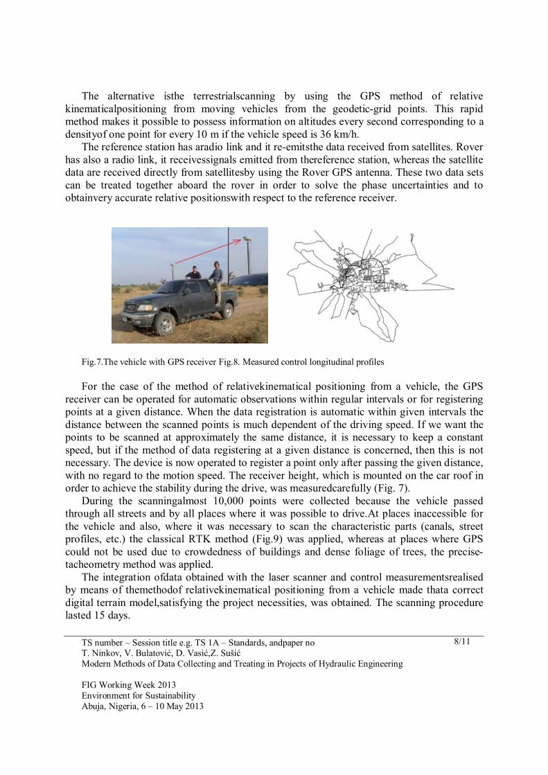
The satellitehigh-resolution frames have demonstrated a high potential in forming the frames to national maps (charts) of all kinds and purposes. In addition to geometric data offered by the digital terrain model for the necessities of determining the basins and sub-basins, a very important role belongs to the orthophoto map as a geocoded digital raster photograph,on the basis of which different space forms can be identified.The satellitehigh-resolution frames have demonstrated a high potential in forming the frames to planning anddesigning of various kinds and purposes. What is attractive to many potential users is just the meter resolution which, practically, makes it possible to extract the objects appearing in the majority of digital cartographic products. The Quick Bird satellite is a commercial satellite wth the highest resolution available in the commercial market. (Fig.2).
Fig. 2: Satellite frame “Quick Bird” with measured longitudestreet profiles(left), digital terrain model with equidistance of 5 m (right)
The high resolutionandthe excellent geometricquality of satelliteframes make it possible to generateorthophoto maps with scales 1:2500, 1:5000, 1:10000, of different thematic contents andwith such quality which can satisfy the most rigorous world requirements and standards ofconventional cartography.
For maps with scales from1:2500, 1:5000 to 1:10000 the use of digitalorthophotogrametryoffers important advantages because digital orthophoto-mapsgive a user a positionalaccuracy compatible withthe requirements and standards oftopographicmaps. Also, due to the abundant information contained by a photograph, an orthophoto-mapis an extremelyuseful and intuitivetool,not only for the purpose of charting, but especially for the purposes of planning andengineering process ofdeciding.

TS number – Session title e.g. TS 1A – Standards, andpaper noT. Ninkov, V. Bulatović, D. Vasić,Z. SušićModern Methods of Data Collecting and Treating in Projects of Hydraulic Engineering
FIG Working Week 2013Environment for Sustainability Abuja, Nigeria, 6 – 10 May 2013
6/11
4. REALISED GEODETIC MEASUREMENTS AND PRODUCTION OFDIGITAL TERRAIN MODEL
4.1 Technique of mobile laser scanning
The implementation of the most recent laser scanning techniquecombined withthe high-precision navigation system, yields a system for 3D scanning of roads, buildings andtrees from moving vehicles.
The device utilizes several laser scanners where each of them performs up to 10.000 measurements per secondwith a scanning speed of at most 100 acts of scanning per second. In the case of this system different scanners, located at different places of the car platform,can be utilized. InFig. 3the technique of mobile laser scanning by using the ”MDL Dynascan” system, model 250, is presented.
Fig. 3 : MDL Dynascan model 250.
The system is specially designed for a rapid 3D mapping of motorways, roads, runways, railways, infrastructure objects etc. The data can be registeredin a normaldrive speed, the survey of urban environments over a relatively short time is also possible.Such a system makes it possible to register every detail along the scanning corridor, including road verges, traffic signs, surface lines, object facades and everything entering the viewfield of the scanner.Combining the data scanned with laser with the video andthe photographs makes it possible to produce a very precise 3D model. Such a system makes it possible to scanthe corredor very quickly (even 60km/h – recommended not higher than30 km/h)with high

TS number – Session title e.g. TS 1A – Standards, andpaper noT. Ninkov, V. Bulatović, D. Vasić,Z. SušićModern Methods of Data Collecting and Treating in Projects of Hydraulic Engineering
FIG Working Week 2013Environment for Sustainability Abuja, Nigeria, 6 – 10 May 2013
7/11
precision satisfying various necessities. One of them would also be thecanal scanning for the purposes ofreconstructing and designing.
LIDAR scanning, even 350,000 points per second, a large number of points are obtained with georeference coordinates.Such a set of points is not suitable to any application in the process ofdesigning, consequently, a data treatment is unavoidable. To generate 3D modelswith all technical characteristics necessary to all kinds of space analysesand new designingis possible by means of a numerico-graphical data treatment, by using a specialised software.One day of scanning requires about 7 daysfor data treatment in order to obtain the corresponding formats of graphical presentations suitable to standard designing in spaceplanning, urbanism and other engineering branches.
By a computer treatment of the collected cloud of points (Fig. 4)it is possible to generate a 3D model and from it thecharacteristic profiles (Figs. 5 and 6). By comparing them to the profiles generatedfrom the existing topographic documentation or to the profilesfrom the same measurementafter a time interval it is possible to quantifythe changes and determinethe degree of terrain degradation.
Fig. 4. Cloud of points forscanned canal
Fig.5. 3D canal model Fig.6.Longitudinal profile of main canal
4.2 Control profiles and scanningof inaccessible parts
Longitudinal profile of main chanel
360
361
362
363
364
365
366
367
0 2000 4000 6000 8000 10000 12000
Distance
Ele
vati
on
TerainWater levelBottom
TS number – Session title e.g. TS 1A – Standards, andpaper noT. Ninkov, V. Bulatović, D. Vasić,Z. SušićModern Methods of Data Collecting and Treating in Projects of Hydraulic Engineering
FIG Working Week 2013Environment for Sustainability Abuja, Nigeria, 6 – 10 May 2013
8/11
The alternative isthe terrestrialscanning by using the GPS method of relative kinematicalpositioning from moving vehicles from the geodetic-grid points. This rapid method makes it possible to possess information on altitudes every second corresponding to a densityof one point for every 10 m if the vehicle speed is 36 km/h.
The reference station has aradio link and it re-emitsthe data received from satellites. Rover has also a radio link, it receivessignals emitted from thereference station, whereas the satellite data are received directly from satellitesby using the Rover GPS antenna. These two data sets can be treated together aboard the rover in order to solve the phase uncertainties and to obtainvery accurate relative positionswith respect to the reference receiver.
Fig.7.The vehicle with GPS receiver Fig.8. Measured control longitudinal profiles
For the case of the method of relativekinematical positioning from a vehicle, the GPS receiver can be operated for automatic observations within regular intervals or for registering points at a given distance. When the data registration is automatic within given intervals the distance between the scanned points is much dependent of the driving speed. If we want the points to be scanned at approximately the same distance, it is necessary to keep a constant speed, but if the method of data registering at a given distance is concerned, then this is not necessary. The device is now operated to register a point only after passing the given distance, with no regard to the motion speed. The receiver height, which is mounted on the car roof in order to achieve the stability during the drive, was measuredcarefully (Fig. 7).
During the scanningalmost 10,000 points were collected because the vehicle passed through all streets and by all places where it was possible to drive.At places inaccessible for the vehicle and also, where it was necessary to scan the characteristic parts (canals, street profiles, etc.) the classical RTK method (Fig.9) was applied, whereas at places where GPS could not be used due to crowdedness of buildings and dense foliage of trees, the precise-tacheometry method was applied.
The integration ofdata obtained with the laser scanner and control measurementsrealised by means of themethodof relativekinematical positioning from a vehicle made thata correct digital terrain model,satisfying the project necessities, was obtained. The scanning procedure lasted 15 days.

TS number – Session title e.g. TS 1A – Standards, andpaper noT. Ninkov, V. Bulatović, D. Vasić,Z. SušićModern Methods of Data Collecting and Treating in Projects of Hydraulic Engineering
FIG Working Week 2013Environment for Sustainability Abuja, Nigeria, 6 – 10 May 2013
9/11
Fig. 9. Canal measurements in the city
4.3 Generating digital terrain model
After finishing the data gathering a high-quality frame was obtained for the purpose of generating a digital terrain model. The digital terrain model is astandard digital format forrepresenting the altitude terrain presentationconsisting of points in a matrix form at the same mutual distance or points at the corners of scalenetriangles. Every corner of the matrix or triangle contains data on the altitude of the terrain part which it represents. The precision of the digital terrain model in the surface representing depends directly on the distance between the matrix points. It is clear that the shorter the distance between the points is, the better is the representation of the given surface by the digital terrain model and more relief details will be presented. The digital terrain model offers a fine frame for all kinds of 3D presentations. Its important advantage is that it makes it possible to have a 3D visualizationof all 2D frames, a geo-statistic calculation andanalysisof complex spacemodeling. Thus the digital terrain model yields directly the data such as: altitude, terrain aspect and inclination; even any modern software makes it possible to generate automatically the contour line as well as the corresponding thematic maps (Fig. 10).
Fig.10: Contour line on the basis ofDMT Fig. 11: Generated catchments

TS number – Session title e.g. TS 1A – Standards, andpaper noT. Ninkov, V. Bulatović, D. Vasić,Z. SušićModern Methods of Data Collecting and Treating in Projects of Hydraulic Engineering
FIG Working Week 2013Environment for Sustainability Abuja, Nigeria, 6 – 10 May 2013
10/11
The data used in the realization of the digital terrain modelare gathered by applying the mobile-laser-scanning technique, by applying the precise-electron-tachometrymethodand thecontrol profilesobtained by means ofthe GPSmethod of continuous kinematical measuring. In order to have a precise presentation of the terrain configuration at the places where for the purposes of planning and designing a high precision level is required, the data gathering is realized by applying the precise-tachometry method. By analyzing the digital terrain model, by determining the basins and sub-basins, it is necessary to provide suitable height differences in order to direct water to be outside the city (Fig. 10).
5. BASIN DESIGNING AND PROPOSED SOLUTION
By analysing the digitalterrain model, by determining the basins and sub-basins (Fig. 11), it is necessary toprovide suitable height differences in order to direct water to be outside of the city. A problem arises due to a few depressions in which the water remains over the rain season and a major part of the dry one. The conditions in them are favourable for swarming of mosquitoes which cause malaria, the water is also contaminated and, therefore, it is one ofthe most frequent causes to contagious illnesses. Among the solutions is the possibility to dig canals by which the water is removed from the downtown to be outside of the city.
In order to form the project of primary and secondary canals the area under analysis was divided into eight sub-basins (Fig. 11). The role of the secondary canalsis to direct the water from the downtown to the main canal which goes outside and directs all the water to the periphery. Along a part of the old bed in the zone of newly designed canal 3, one should provide a counter-height difference in two phases. In the first phase the depressions will be filled out with the material obtained by excavating the main canal, whereas in the second one by digging secondary canal No 3 the counter-height difference will be obtained.The position of flowing in for canalNo 3 to the main one is the flowing-outpoint for the sub-basin in zone B.
Fig. 12: Izgradnja kanalaFig. 13: Operativni poligon
By the level of this flowing-outpoint with the minimumheight difference necessaryforwater flowing off (25cm/km) the canal bottom in height is defined. The main canal, together with the secondaryones, provides a good base for later densification and constructionof the complete sanitary sewer system of the city. Based on the information concerning the average annual precipitation level, the meteorological stations including the

TS number – Session title e.g. TS 1A – Standards, andpaper noT. Ninkov, V. Bulatović, D. Vasić,Z. SušićModern Methods of Data Collecting and Treating in Projects of Hydraulic Engineering
FIG Working Week 2013Environment for Sustainability Abuja, Nigeria, 6 – 10 May 2013
11/11
diagram of intensity, duration and frequency for towns Kano and Maiduguri, the diurnal quantity of precipitation for the last season (2007) for Potiskum, Damaturu and Nguru, the size of the canals is determined. Such a solution offers the possibility of directing all the water, which was retained in the city, to the main canal by using the secondary ones. The main canal directs all the water beyond the city and, consequently, it becomes possible to build an … in the territory outside the cityexterior which would water supply for agriculture areas and drinking for cattle.
After finishing the analysis and determination of basins the survey of geodetic activities concerning the construction of the designed canal and satellite objects (Fig. 12) started. Since a good frame for designing was provided,a unique network comprising the whole of the city, with unique transformation parameters was developed, an operative polygon near the location for the construction of the main canal (Fig. 13) is developed.
6. CONCLUSION
Modern data-collecting methods can to a high extent quicken and improve the formation quality for 3D topographic frames which are necessary, because the quality of the works carried out depends on the quality of the frames. The project of drainage for the city of Damaturu in Nigeria realized in phases, thanks to the high-quality 3D frames is going on well. In 2008-2009 the works on digging the main canal and removing pools in the downtowntook place. Over the first 3 km the cement works also took place. During the rain season in 2009 Damaturu suffered numerous floods, but now the floods in its downtown belong to the past.At locations, where earlier there were pools, after shooting earth new, very attractive, parcels, suitable for building, have arisen. The earth and cement works on the main canal and secondary ones should be finished soon. As open questions remain the constructions of the municipal sanitary sewer and reservoir on the exterior area. The river displacing often appears as a big problem, because the natural height differences are changed, microclimate and natural reserves are menaced, but in the case of temporary flows appearing as consequence of large precipitation, their displacing in order to be beyond the populated areas, can diminish, or even, eliminate one of the major contagion causes.
REFERENCES
[1] P. Vaniček, E. Krakiwsky, „GEODEZIJA: KONCEPTI“, Београд 1999.[2] K. Mihailović, I. Aleksić, „Koncepti mreža u geodetskom premeru“, Beograd 2008.[3] V. Bulatović, T. Ninkov, Z.Sušić, „Savremene metode generisanja3D topografskih
podlogakao osnova planiranja i projektovanja“, Novi Sad, iNDiS 2009.[4] T.Ninkov, V.Bulatović, Z. Sušić, ”LASER Scanning applications in projects with
linear structures and objects”.
CONTACTS1. Toša Ninkov PhD in geodesy, Full Professor, Faculty of technical sciences Novi Sad,
Email:[email protected] Web site: www.ftn.uns.ac.rs