Automatic Lens Distortion Correction Using One-Parameter Division Models

Modeling the temporal behavior of distortion productotoacoustic emissions
Arnold TubisDepartment of Physics, Purdue University, West Lafayette, Indiana 47907
Carrick L. TalmadgeNational Center for Physical Acoustics, University of Mississippi, University, Mississippi 38677
Christopher TongDepartment of Physics, Purdue University, West Lafayette, Indiana 47907
~Received 3 September 1999; revised 29 November 1999; accepted 6 December 1999!
The temporal behavior of the 2f 12 f 2 distortion product otoacoustic emission is theoreticallyinvestigated for the case in which the lower frequency (f 1) primary tone is on continuously, and thehigher frequency (f 2) one is pulsed on and [email protected]., Talmadgeet al., J. Acoust. Soc. Am.105,275–292~1999!#. On physical grounds, this behavior is expected to be characterized by variousgroup delays associated with the propagation of~1! the f 2 cochlear primary wave between thecochlear base and the primary distortion product generation region aroundx2 ~the f 2 tonotopicplace!, and~2! the 2f 12 f 2 cochlear distortion product~DP! waves between the cochlear base, theprimary generation region of the distortion product, and the region around the 2f 12 f 2 tonotopicplace where the generated apical moving DP wave is reflected toward the cochlear [email protected].,Talmadgeet al., J. Acoust. Soc. Am.104, 1517–1543~1998!#. An approximate analytic expressionis obtained for this behavior from the analysis of the Fourier integral representation of the auditoryperipheral response to the primary stimuli. This expression also approximately describes thetransient build-up of the components of different latencies in terms of the damping properties of thecochlear partition. It is shown that considerable caution must be applied in attempting to relate phasederivatives of the distortion product otoacoustic emissions for steady state stimuli and the physicaltime delays which are associated with the temporal behavior of a distortion product emission in thecase of a pulsed primary. ©2000 Acoustical Society of America.@S0001-4966~00!03503-7#
PACS numbers: 43.64.Bt, 43.64.Ha, 43.64.Jb@BLM #
nt
orst
tab
ing
nits
oth
s-
ts
DP
s thetatethe
hethe
ce-
tal
e:
ar
andalleas toes,
INTRODUCTION
If a stimulus consisting of tones of two or more frequecies is presented to the ear, nonlinear signal processing incochlea results in the production of intermodulation disttion products~DPs!. These may be detected psychoacoucally or as objective acoustic signals in the ear canal~distor-tion product otoacoustic emissions or DPOAEs! ~reviewed inTalmadgeet al., 1998, 1999!. In the case of a two-tonestimulus of frequenciesf 1 and f 2 (. f 1), the DPOAE withfrequency 2f 12 f 2 is the largest under many experimenconditions. The amplitude and phase of this DPOAE canextracted from the ear canal recording by signal processChanges in the level and phase of the DPOAE with chanin the levels and frequencies of the two external tones~pri-maries! provide us with insight into the mechanisms resposible for the generation of this distortion product andtransmission back to the ear canal.
It is generally understood that the generation regionthe DPs in the cochlea is near the maximal overlap ofcochlear waves evoked by the external tones~e.g., Hall,1974; Kemp and Brown, 1983!. There has been some diagreement, however, over whether the DPOAE~which is theDP signal as measured in the ear canal! is entirely comprisedof a signal component originating at the generator region~forexample, He and Schmiedt, 1993, 1996, 1997; Sunet al.,1994a,b! or whether it is a combination of two componen
2112 J. Acoust. Soc. Am. 107 (4), April 2000 0001-4966/2000/107
-he-i-
leg.es
-
fe
~the so-called ‘‘two-source’’ model!, one originating aroundthe generator region and the other originating near thetonotopic location~reviewed in Talmadgeet al., 1998!. In-vestigators who have assumed that the generator region isole source of the DPOAE have used the steady sDPOAE phase characteristics in an attempt to estimatetime it takes for the two primary tone signals to travel to toverlap region and the generated DPOAE signal to reachexternal ear~e.g., Kimberleyet al., 1993; O’Mahoney andKemp, 1995; Moulin and Kemp, 1996a, b; Bowmanet al.,1997, 1998; Schneideret al., 1999!. ~See Sec. IV of thispaper for some potential pitfalls associated with this produre.!
The results of recent investigations, both experimen~e.g., Kummeret al., 1995; Brownet al., 1996; Gaskill andBrown, 1996; Stoveret al., 1996; Talmadgeet al., 1999! andtheoretical~reviewed in Talmadgeet al., 1998!, have givenstrong support for the following underlying physical picturThe 2f 12 f 2 DPOAE is initially produced in a region~usu-ally called thegenerationor overlap region! where, as justmentioned, the activity patterns for the primary cochlewaves overlap maximally~near the tonotopic site for thef 2
primary!. DP waves emerge and propagate both basallyapically from the generation region. A fraction of the basmoving wave is transmitted through the base of the cochand into the middle ear and ear canal, where it contributethe DPOAE signal. If the cochlea had no inhomogeneiti
2112(4)/2112/16/$17.00 © 2000 Acoustical Society of America

ernsl osiitstedadoei-in
teo
ionthseoroee
ndod
ry
else
i-r
mn
nionpicofeAE
c-ioind
gr.
aethlu
ical
vee
ichadyne.lays
ar,pret-av-in
ofow
ofsionin
ticoxi-dis-
thene-ed
s of
ow
isd-ec-
ariondis-efor
ph-
al,
the apically moving DP wave would simply damp out aftpassing its tonotopic site. However, if the cochlear respogives rise to a tall/broad activity pattern, then a small leveinhomogeneity of the cochlear properties may produce anificant reflection of the apically moving DP wave aroundtonotopic site. This reflection mechanism was first suggesby Zweig and Shera~Shera and Zweig, 1993; Zweig anShera, 1995; see also Talmadge and Tubis, 1993; Talmet al., 1997, 1998, 1999!. This reflected DP wave would alsbe partially transmitted through the cochlea and into thecanal, where it would combine with the signal from the intial basally moving DP wave to produce a characteristicterference behavior~local maxima and minima of theDPOAE amplitude as the primary frequencies are varied!. Inaddition to the ear canal signals from the initially generaDP waves, there would also be a series of other signal ctributions in the ear canal from the partial transmissthrough the cochlear base of basally moving DP wavesoriginate from multiple reflections from the cochlear baand from around the DP tonotopic site. These additional ctributions to the DPOAE signal would, of course, also pduce interference effects.@For a detailed discussion of thesadditional interference terms see, e.g., Shera and Zw~1992!, Zweig and Shera~1995!, and Talmadgeet al.~1998!.#
Formal expressions for the DPOAE amplitude aphase, including the effects of multiple internal reflectionsthe DP waves in the cochlea, have been derived by Talmaet al. ~1997, 1998, 1999! for the case of steady state primatones. As was shown by Talmadgeet al. ~1999!, it is instruc-tive to also study the temporal behavior of DPOAEs whone of the primaries is on steady state but the other is puon and off.@This paradigm is to be distinguished from thone in which both primaries are pulsed on and off~e.g.,Martin et al., 1998!, which is harder to interpret theoretcally.# It is especially easy to interpret data obtained neaminimum in the DPOAE fine structure where the two coponents are almost 180 degrees out of phase. In this instaas was demonstrated by Talmadgeet al. ~1999!, the appear-ance of a null in the DPOAE amplitude following the turn oof the pulsed primary clearly indicates that the contributto the DPOAE from the reflection around the DP tonotosite is the dominant one. Conversely, the appearancenull in the DPOAE amplitude following the turn off of thpulsed primary indicates that the contribution to the DPOfrom the generation region is the dominant one.
If the effect of cochlear nonlinearity is taken into acount only to the lowest nonvanishing order, the connectbetween the steady state DPOAE signal and the signalpulsed primary paradigm is, in principle, straightforwarThe latter can be simply represented by a Fourier intewhose integrand involves the complex steady state signal1 Inthis paper, the temporal behavior of the 2f 12 f 2 DPOAE ina pulsed (f 2) primary paradigm~with the f 1 primary onsteady state! is studied theoretically. In order to obtainphysically transparent result, the integrand of the Fourierpression for this temporal behavior is approximated sothe integral may be evaluated analytically using the calcuof residues~e.g., Arfken and Weber, 1995, pp. 414–432!.
2113 J. Acoust. Soc. Am., Vol. 107, No. 4, April 2000
efg-
d
ge
ar
-
dn-
at
n--
ig
fge
ned
a-ce,
a
na
.al
x-ats
The result is then expressed in terms of the basal and apcochlear reflectances, the various relevant latencies~those forthe propagation of the primaryf 2 wave from the cochlearbase to thef 2 tonotopic site, the propagation of the DP wafrom the f 2 tonotopic site to the DP tonotopic site, and thpropagation of the DP wave from thef 2 tonotopic site to thecochlear base!, and the cochlear damping parameters whcharacterize the approach of the DPOAE behavior to stestate conditions after the turn on of the pulsed primary toThe appearance of latencies in their true role as time de~rather than as phase derivatives of steady state signals! willhopefully make their physical origin and significance cleand help researchers to avoid the dangers of always intering the phase derivatives of the steady state DPOAE behiors as physical time delays. This point will be discussedSec. IV.
The relevant formal expressions for the 2f 12 f 2
DPOAE under steady state and pulsed (f 2) primary condi-tions are given in Sec. I. Approximations of the integrandthe Fourier integral for the pulsed primary case, which allthe integral to be evaluated analytically using the calculusresidues, are introduced in Sec. I C. The analytic expresis obtained in Sec. II, and its implications are exploredSecs. III and IV.
I. THE 2f 1Àf 2 DPOAE
A. Steady state primaries
The basic formulas for various types of otoacousemissions, and details on the underlying model and apprmations used to obtain them, have been extensivelycussed in Talmadgeet al. ~1998!, to which the reader is di-rected for the precise definitions and meanings ofsymbols used in this paper. The model used was a odimensional macromechanical model with a time-delaystiffness component in the basilar membrane mechanicthe form suggested by Zweig~1991!. The model also in-cludes simplified models of the middle and outer cars. A llevel of spatial inhomogeneity of cochlear properties~Sheraand Zweig, 1993; Zweig and Shera, 1995! is assumed. Inconjunction with the tall/broad activity pattern whichgiven by the Zweig form of the cochlear partition impeance, the inhomogeneities give rise to cochlear wave refltions. A simple third-order nonlinearity in the cochledamping function is introduced to account for the generatof DPOAEs, as well as to stabilize SOAEs. For reasonscussed in Talmadgeet al. ~1998!, the essential features of thresults obtained with the model are expected to be validmore elaborate and realistic models of the auditory periery.
For a steady state ‘‘calibrated’’ driving pressure,Pdrss(t),
given by
Pdrss~ t !5A1eiv1t1A2eiv2t1complex conjugate, ~1!
whereA1 and A2 are complex constants, the complex 2f 1
2 f 2 DPOAE pressure signal amplitude in the ear canPdp
ss(v1 ,v2 ,vdp), (vdp52v12v2), is given by Eq.~162!of Talmadgeet al. ~1998!,
2113Tubis et al.: Temporal behavior of otoacoustic emissions

s
ia
of
hent
-P
the
,n
e-in
by
of
dd-r-
x
rthes2
to
ar-altate
Pdpss~v1 ,v2 ,vdp!
52Tpd~vdp!kow~vdp!
kr~0,vdp!1kl~0,vdp!
3r0~v1 ,v2!
Dsm~0,vdp!
11Ra~vdp!Rd~v1 ,v2!
12Ra~vdp!Rb~vdp!
3I r~`,v1 ,v2!, ~2!
[Pl~v1 ,v2 ,vdp!1Ra~vdp!Pr~v1 ,v2 ,vdp!
12Ra~vdp!Rb~vdp!. ~3!
Some of the relevant expressions for the various termEq. ~2! are
I r ,l~x,v1 ,v2!5E0
x
dx8v0~x8!x r2~x8,v1!x r* ~x8,v2!
3x r ,l~x8,vdp!, ~4!
r0~v1 ,v2!5isbmk0
2eg~2v12v2!3br2~0,v1!br* ~0,v2!
bnl2 ,
~5!
v0~x!5v0ce2kvx1v1c , ~6!
Rd~v1 ,v2!5I l~`,v1 ,v2!
I r~`,v1 ,v2!5
Pr~v1 ,v2 ,vdp!
Pl~v1 ,v2 ,vdp!, ~7!
br~0,v!52Gme~v!kow~v!Pdr~v!
sbmDsm~0,v!~kr~0,v!1kow~v!!, ~8!
Pdr~v1,2!5A1,2, ~9!
c r~x,v!>Ak~0,v!
k~x,v!expH 2 i E
0
x
k~x8,v!dx8J , ~10!
c l~x,v!>Ak~0,v!
k~x,v!expH 1 i E
0
x
k~x8,v!dx8J , ~11!
k~x,v!5k0v
ADsm~x,v!, ~12!
Dsm~x,v!5v02~x!2v21 ivg0~x!1r fv0~x!2
3e2 ic fv/v0~x!1rsv0~x!2e2 icsv/v0~x!, ~13!
x r ,l~x,v!5Dsm~0,v!
Dsm~x,v!c r ,l~x,v!, ~14!
and
Ra~v!'22r 0k0
2v2
W0~v!Dsm2 ~0,v!
E0
`
dxv02~x!x r
2~x,v! r ~x!.
~15!
Herer (x) is a function that gives a pseudo-random Gaussnumber with ^ r 2(x)&51, W0(v)5c r(x,v)c l8(x,v)2c r8(x,v)c l(x,v) is the Wronskian and is independentx, andr 0 characterizes the magnitude of the roughness.
For simplicity, it is assumed that
Rb~v!5Rbe2 ivtb, ~16!
2114 J. Acoust. Soc. Am., Vol. 107, No. 4, April 2000
in
n
where Rb is a constant, and that apical reflections of tprimary f 1 , f 2 cochlear waves can be ignored. If significaapical reflections of the primaries were present, Eq.~8!would have to be modified according to Eqs.~53! and~97! ofTalmadgeet al. ~1998!, since internal reflection of the primaries would lead to an additional modulation of the Dgenerator due to the variation in the activity patterns ofprimaries with frequency.
The WKB approximation~e.g., Mathews and Walker1964; Zweiget al., 1976! has been used for the transpartitiopressure basis functions@Eqs.~10!–~13!#. The explicit phasebehaviors given by this approximation will be useful in driving approximate expressions for various time delaysterms of spatial integrals of]k(x,v)/]v.
B. Pulsed f 2 primary
If, instead of the steady state driving pressure givenEq. ~1!, only the f 1 primary is on steady state, and thef 2
primary is turned on att50, Eq. ~1! would be replaced by
Pdron~ t !5A1eiv1t1Q~ t !A2eiv2t1complex conjugate,
5A1eiv1t1A2
2p i E2`
`
dv28eiv28t
v282v22 i e
1complex conjugate, ~17!
wheree is a positive infinitesimal, andQ(t) is the Heavisidetheta function given by
Q~ t 
d
le.
ad
en
m-a
of
dith
fo
f
teth
erto
:tho
r-
o
ir
ave
t
q.
g
he
sso-andn
be
Pdpon~ t !52
e2iv1t
2p i E2`
`
dv28e2 iv28t
v282v21 i e
3Pdpss~v1 ,v28,2v12v28!1complex conjugate,
~20!
wherePdpss(v1 ,v2,2v12v2) is given by Eq.~2!, and where
we have usedvdp52v12v28 . ~The reader who finds it dif-ficult to understand the procedure used here is referreAppendix B of this paper, where the same methodologyillustrated in the context of DP generation for a simpdriven nonlinear oscillator with a single degree of freedom!Pdp
off(t) is obtained from Eq.~20!, with e replaced by2e, andwith an overall minus sign, and describes how the stestate DP response decays after the turn off of thef 2 primaryat t50.
Because of the rather complicated functional depdence of the integrand of Eq.~20! on v28 , the evaluation ofPdp
on(t) is a very formidable task. In the next section, a nuber of simplifying approximations will be applied to the integrand so as to permit the analytic evaluation of the relevpart of Pdp
on(t) via contour integration and the calculusresidues.
C. Approximate representation of Pdpon„t …
The experimental temporal measurement of the 2f 1
2 f 2 DPOAE under pulsedf 2 primary conditions~Talmadgeet al., 1998! essentially entails the detection of the steastate 2f 12 f 2 DPOAE component, and the components wfrequencies in close proximity to 2f 12 f 2 and decaying am-plitudes~which determine the transient behavior!. This sug-gests a procedure in which thev28 dependence oPdp
ss(v1 ,v28,2v12v28) in Eq. ~20! is approximated so as temphasize this dependence in the neighborhood ofv285v2
~especially the pole behavior!. Furthermore, the integrand oEq. ~20! is sharply peaked nearv285v2 , which means thatquantities that slowly vary over the region where this ingrand is large may either be assumed constant, and for osufficiently slowly varying quantities, only the leading ordcontribution to the variation of the quantity with respectv22v28 will need to be considered.
The following approximations will therefore be made~i! It is assumed that the effect of the middle ear on
DPOAE amplitude and phase is a slowly varying functionv2 , so that
F~v1 ,v28,2v12v28![2Tpd~2v12v28!kow~2v12v28!
kr~0,2v12v28!1kl~0,2v12v28!
3r0~v1 ,v28!
D~0,2v12v28!
'F~v1 ,v2,2v12v2!, ~21!
whereF(v1 ,v2,2v12v2) characterizes the effects of foward and reverse transmission through the middle ear.
~ii ! The level of the 2v12v2 DP wave is assumed tslowly vary nearv2 , so that
2115 J. Acoust. Soc. Am., Vol. 107, No. 4, April 2000
tois
y
-
-
nt
y
-er
ef
x r~x,v28!'x r~x,v2!Dsm~x,v2!
Dsm~x,v28!e2 i t2~x!~v282v2!, ~22!
x r~x,2v12v28!'x r~x,2v12v2!Dsm~x,2v12v2!
Dsm~x,2v12v28!
3e2 i t~x,vdp!~v22v28!, ~23!
x l~x,2v12v28!'x l~x,2v12v2!Dsm~x,2v12v2!
Dsm~x,2v12v28!
3ei t~x,vdp!~v22v28!, ~24!
t2~x!5E0
x
dx8]k~x8,v28!
]v28U
v285v2
, ~25!
t~x,vdp!5E0
x
dx8]k~x8,vdp!
]vdpU
vdp52v12v2
. ~26!
Note also that the phase variations ofx r(x,v28), x r(x,2v1
2v28), andx l(x,2v12v28) have been approximated by thefirst-order expansions inv22v28 . The coefficients of theseexpansions are the group delays,t2(x) andt(x,vdp), whichare those for the propagation of narrow-band cochlear wpackets of center frequenciesv2 andvdp , respectively, be-tween locationsx' x(v2) and 0. Note that an equivalenassumption is that the group delays oft2(x) and t(x,vdp)are slowly varying over the region where the integrand in E~20! is nonnegligible.
~iii ! The level and phase of the coefficient multiplyinthe integral expression for the reflectanceRa(v) in Eq. ~15!is assumed to be slowly varying, so that
f ~vdp8 !uvdp8 52v12v
28[
2r 0k02~vdp8 !2
W0~vdp8 !Dsm2 ~0,vdp8 !
Uv
dp8 52v12v28
'2r 0k0
2~2v12v2!2
W0~2v12v2!Dsm2 ~0,2v12v2!
. ~27!
~iv! The group delaytdp(x), which is that for a narrow-band cochlear wave packet of center frequencyvdp , whichis propagating between the positions,x50 andx5 x(vdp),will be assumed to slowly vary over the region where tintegrand of Eq.~20! is nonnegligible, so that
tdp~x!5E0
x
dx8]k
]vdp~x8,vdp!U
vdp52v12v2
. ~28!
~v! Finally, the branch cuts associated with thev28 de-pendence in Eqs.~10! through~12! will be neglected. This isequivalent to assuming that the branch points and their aciated branch cuts lie outside the region where the integrof Eq. ~20! has its maximum. In this case, only the variatioof the functions containing branch cuts@such asADsm(0,v)#within the region where this integrand is maximum needconsidered.
With all of these approximations introduced, Eq.~20!becomes
2115Tubis et al.: Temporal behavior of otoacoustic emissions

Pdpon~ t !52
e2iv1t
2p iF~v1 ,v2,2v12v2!E
2`
`
dv28e2 iv28t
v282v21 i e H F E0
`
dx8v0~x8!x r2~x8,v1!x r* ~x8,v2!x r~x8,2v12v2!
3Dsm* ~x8,v2!
Dsm* ~x8,v28!
Dsm~x8,2v12v2!
Dsm~x8,2v12v28!ei @ t2~x8!1t~x8,vdp!#~v282v2!G1F f ~2v12v2!E
0
`
dx8v02~x8!x r
2~x8,2v12v2!
3 r ~x8!Dsm
2 ~x8,2v12v2!
Dsm2 ~x8,2v12v28!
e22i tdp~x8!~v22v28!E0
`
dx9v0~x9!x r2~x9,v1!x r* ~x9,v2!x l~x9,2v12v2!
3Dsm* ~x9,v2!
Dsm* ~x9,v28!
Dsm~x9,2v12v2!
Dsm~x9,2v12v28!ei @ t2~x9!2t~x9,vdp!#~v282v2!G J H 12 f ~2v12v2!Rbe2 i tb~2v12v2!E
0
`
dx8v02~x8!
3x r2~x8,2v12v2! r ~x8!
Dsm2 ~x8,2v12v2!
Dsm2 ~x8,2v12v28!
ei @tb12tdp~x8!#~v282v2!J 21
1complex conjugate. ~29!
-
ofl’’
e
omeP
and
he
d
n-
aralite,
aln-andm-
he
st
rst
In the following sections, it will be shown that this expression can be approximately represented as
Pdpon~ t !'Pdp
gen~ t !1Pdprefl~ t !1¯ . ~30!
Here the superscript ‘‘gen’’ denotes the componentPdp
on(t) from the generator region, and the superscript ‘‘redenotes the component from the reflection site. The timdependent DP componentsPdp
gen(t) and Pdprefl(t) have the
steady state analogues Plss(v1 ,v2 ,vdp) and
Ra(vdp)Prss(v1 ,v2 ,vdp) in Eq. ~3!. In the next section, it
will be shown that the time constants,t2(x) andt(x,vdp),may be approximately set equal to their values atx5 x2
5 x(v2), and the time constanttdp(x) set equal to its valueat x5 x(2v12v2). Then,
tgen[2]
]vdparg@Pl~x,v1 ,v2 ,vdp!#> t21t~ x2 ,vdp!,
~31!
t refl[2]
]vdparg@Ra~vdp!Pr~x,v1 ,v2 ,vdp!#
> t212tdp2t~ x2 ,vdp!, ~32!
where
t25 t2~ x2!, tdp5 tdp~ x2!, ~33!
are, respectively, the latency of the DPOAE component frthe generation region and the latency of the componwhich results from the initial reflection of the generated Dwave around the DP tonotopic site. Note thattgen and t refl
characterize, respectively, the rate of change of the phfrom the initial contribution from the generation region afrom the DPOAE reflection site.
Section II of this paper is devoted to the extraction of tvarious DPOAE temporal components from Eq.~29!. Thelatencies of these components are concisely summarizeSec. II A.
2116 J. Acoust. Soc. Am., Vol. 107, No. 4, April 2000
f
-
nt
se
in
II. EVALUATION OF THE DPOAE SIGNAL IN THECASE OF A PULSED f 2 PRIMARY
A. Component latencies
On physical grounds, the pulsing on of thef 2 primary isexpected to result in a series of 2f 12 f 2 components of in-creasing latency. The first, corresponding to the initially geerated component, will have a latency aroundtgen, given byEq. ~31!. The next will correspond to the signal in the ecanal which results from the reflection of the initial apicmoving generated wave from around the DP tonotopic swhose latency will be approximately given byt refl in Eq.~32!. This will be followed by the signal in the ear canwhich results from successive reflections of the initially geerated basal-moving wave, from the base of the cochleafrom around the DP tonotopic site. The latency of this coponent will be given approximately bytgen12tdp1tb ,wheretdp andtb are defined by Eqs.~33! and ~16!, respec-tively. The next signal component will have latency,t refl
12tdp1tb , and so on. In summary, the latencies of tvarious components will be approximately given by
tgen,n5 tgen1n~2tdp1tb!; n50,1,2,3,... , ~34!
and
t refl,n5 t refl1n~2tdp1tb!; n50,1,2,3,... . ~35!
B. The tgen latency component
The tgen latency component is obtained from the firterm of Eq.~29!, with the $...%21 factor set equal to one. Inorder to evaluate this component, it is convenient to fiperform the integration overv28 ,
2e2iv1t
2p i E2`
`
dv28e2 iv28t
v282v21 i e
Dsm* ~x,v2!
Dsm* ~x,v28!
3Dsm~x,2v12v2!
Dsm~x,2v12v28!ei @ t2~x!1t~x,vdp!#~v282v2!, ~36!
where for simplicity, analytic structures not containingv28are not shown.
2116Tubis et al.: Temporal behavior of otoacoustic emissions

forvalidity,
The time-delayed stiffness terms inDsm(x,v28) @Eq. ~13!# greatly complicate the evaluation of the integral. Therefore,the purpose of obtaining a simple result for the transient build up of the signal, which should at least have qualitativethese terms will be neglected.2 Then
Dsm* ~x,v2!
Dsm* ~x,v28!
Dsm~x,2v12v2!
Dsm~x,2v12v28!'
Dsm* ~x,v2!Dsm~x,2v12v2!
~v02~x!2v28
22 iv28g0~x!!~v02~x!2~2v12v28!21 i ~2v12v28!g0~x!!
5Dsm* ~x,v2!
~v282v0~x!1 ig0~x!/2!~v281v0~x!1 ig0~x!/2!
3Dsm~x,2v12v2!
~2v12v282v0~x!2 ig0~x!/2!~2v12v281v0~x!2 ig0~x!/2!, ~37!
where
v0~x!5Av02~x!2
g02~x!
4, ~38!
and thus the integral in Eq.~36! may be evaluated using the calculus of residues to yield
Q~ t2 t2~x!2t~x,vdp!!Fei ~2v12v2!t2e2iv1te2 i ~v0~x!2 ig0~x!/2!tei @v0~x!2v22 ig0~x!/2#~ t2~x!1t~x,vdp!!
3Dsm* ~x,v2!Dsm~x,2v12v2!
~v0~x!2v22 ig0~x!/2!~2v0~x!!Dsm~x,2v12v0~x!1 ig0~x!/2!G , ~39!
ar
qex
plus terms that have the temporal behaviors,
Q~ t2 t2~x!2t~x,vdp!!ei ~2v11v0~x!1 ig0~x!/2!t ~40!
and
Q~ t2 t2~x!2t~x,vdp!!ei ~6v0~x!1 ig0~x!/2!t. ~41!
In order to obtain analytic results for the DPOAE, a finseries of approximations is required in the integration ovex.The approximations are based on the facts thatg0(x)!v0(x) and that the magnitude of the integrand of thexintegration is peaked aboutx5 x2 , where v0( x2)'v0( x2)'v2 . Accordingly,x in Eqs.~39!, ~40!, and~41! is set equalto x2 , and v0(x)2 ig0(x)/2 in Dsm(x,2v12v0(x)1 ig0(x)/2) is replaced byv2 . Also,
limx→ x2
Dsm* ~x,v2!ei @v0~x!2v22 ig0~x!/2#@ t2~x!1t~x,vdp!#
~ v0~x!2v22 ig0~x!/2!~2v0~x!!
5eg0~ x2!tgen/2. ~42!
The contributions with temporal behaviors described by E~40! and ~41! need not be considered since they can beperimentally distinguished from the~amplitude varying!2v12v2 DPOAE signal.
The final expression for thetgen latency component is
2117 J. Acoust. Soc. Am., Vol. 107, No. 4, April 2000
l
s.-
Pdpgen~ t !5Q~ t2 tgen!e
i ~2v12v2!t~12e2g0~ x2!~ t2 tgen!/2!
3Pl~v1 ,v2,2v12v2!1complex conjugate,
~43!
where
Pl~v1 ,v2,2v12v2!
5F~v1 ,v2,2v12v2!E0
`
dxv0~x!x r2~x,v1!x r* ~x,v2!
3x r~x,2v12v2!. ~44!
The superscript ‘‘gen’’ inPdpgen(t) is used in order to denote
that this component is the direct~shortest latency! contribu-tion to Pdp
on(t) from the generator region.
C. The t refl latency component
From Eq.~29!, the t refl latency component is
Pdprefl~ t !5F~v1 ,v2,2v12v2! f ~2v12v2!
3E0
`
dx8E0
`
dxv02~x8!x r
2~x8,2v12v2! r ~x8!
3v0~x!x r2~x,v1!x r* ~x,v2!x l~x,2v12v2!
3I dprefl~x,x8,v1 ,v2 ,t !1complex conjugate,
~45!
where
2117Tubis et al.: Temporal behavior of otoacoustic emissions

.
I dprefl~x,x8,v1 ,v2 ,t !52
ei2v1t
2p i E2`
`
dv28e2 iv28~ t2 trefl~x,x8!!e2 iv2trefl~x,x8!
v282v21 i e
Dsm2 ~x8,2v12v2!
Dsm2 ~x8,2v12v28!
Dsm* ~x,v2!
Dsm~x,v28!
Dsm~x,2v12v2!
Dsm~x,2v12v28!,
~46!
and
t refl~x,x8!5 t2~x!12tdp~x8!2t~x,vdp!. ~47!
From the discussion of the previous section, it is seen thatDsm(x,2v12v2)/Dsm(x,2v12v28) may be approximated byunity if only the transient signal withv2852v12v2 is being tracked. Also, since the magnitudes of the integrands of thex andx8 integrations are peaked aboutx(v2) andx(2v12v2), respectively, the approximation of settingx,x8 to these values in Eq~46! will be used. Finally, the time-delayed stiffness terms inD(x,v28) will again be dropped andg0 will be assumed to beindependent ofx. Then:
I dprefl~x5 x~v2!,x85 x~2v12v2!,v1 ,v2 ,t !
52ei2v1t
2p i E2`
`
dv28e2 iv28~ t2 trefl!e2 iv2trefl
v282v21 i e
Dsm2 ~ x~2v12v2!,2v12v2!
Dsm2 ~ x~2v12v2!,2v12v28!
Dsm* ~ x~v2!,v2!
Dsm* ~ x~v2!,v28!
'2ei2v1t
2p i E2`
`
dv28e2 iv28~ t2 trefl!e2 iv2trefl
v282v21 i e S i ~2v12v2!g0
2~2v12v28!21~2v12v2!21 i ~2v12v28!g0D 2 ~2 iv2g0!
2v2821v2
22 iv28g0. ~48!
m
In Eq. ~48!, only the residue contributions from poles atv285v22 i e, v22 ig0/2, and 4v12v22 ig0/2, which givecomponents of frequency 2v12v2 , with time varying am-plitudes in the latter two cases, will be retained. Also, tercontaining powers of the dimensionless factorsg0 /v2 ,g0 /(2v12v2),..., will be neglected.~These terms includethe residue contribution fromv2854v12v22 ig0/2.) ThenEq. ~48! has the approximate form,
I dprefl~x5 x~v2!,x85 x~2v12v2!,v1 ,v2 ,t !
'2ei2v1t
2p i E2`
`
dv28e2 iv28~ t2 trefl!
3e2 iv2trefl~ ig0/2!3
~v282v21 i e!~v282v21 ig0/2!3
5Q~ t2 t refl!ei2v1tF e2 iv2t1e2 iv2treflS i
g0
2 D 3
31
2
d2
dv282H e2 iv28~ t2 trefl!
v282v21 i eJ Uv
285v22 ig0/2G
5Q~ t2 t refl!ei ~2v12v2!tF12e2g0t/2
3S 11g0t
21
g02t2
8 D GUt 5t2 trefl
. ~49!
Substitution of the result in Eq.~49! into Eq. ~45! gives thefinal form of thet refl latency component,
2118 J. Acoust. Soc. Am., Vol. 107, No. 4, April 2000
s
Pdprefl~ t !5Ra~2v12v2!Pr~v1 ,v2,2v12v2!
3Q~ t2 t refl!ei ~2v12v2!t F12e2g0t/2
3S 11g0t
21
g02t2
8 D GUt 5t2 trefl
, ~50!
where
Pr~v1 ,v2,2v12v2!5F~v1 ,v2,2v12v2!
3E0
`
dxv0~x!x r2~x,v1!x r* ~x1 ,v2!
3x l~x,2v12v2!. ~51!
D. Components with latencies, tgen, n and t refl, n , nÐ1,and final form of Pdp
on„t …
The expansion of the factor
$12Ra~vdp!Rb~vdp!%21, ~52!
where
Ra~vdp!Rb~vdp!5 f ~2v12v2!Rbe2 i tb~2v12v2!
3E0
`
dxv02~x!x r
2~x,2v12v2! r ~x!
3Dsm
2 ~x,2v12v2!
Dsm2 ~x,2v12v28!
3ei @tb12tdp~x!~v282v2!#, ~53!
in Eq. ~29! in a geometric series inRaRb , gives the contri-butions to the DPOAE with latenciestgen or t refl plus mul-tiples of 2tdp1tb .
2118Tubis et al.: Temporal behavior of otoacoustic emissions
rie
n
f
if
dyhehe
thecy
leient
be-
ge
pet
henthebe
With the same approximations as those used in the thproceeding sections, the contributions with these latencalong with thetgen and t refl latency ones, may be written ithe concise form:
Pdpon~ t !5eivdptH Pl~v1 ,v2 ,vdp! (
n50
`
Ran~vdp!Rb
n~vdp!
3F2nS g0tgen,n
2 D1Ra~vdp!Pr~v1 ,v2 ,vdp!
3 (n50
`
Ran~vdp!Rb
n~vdp!F2n12S g0t refl,n
2 D J1complex conjugate, ~54!
where
tgen,n5t2 tgen,n , ~55!
t refl,n5t2 t refl,n , ~56!
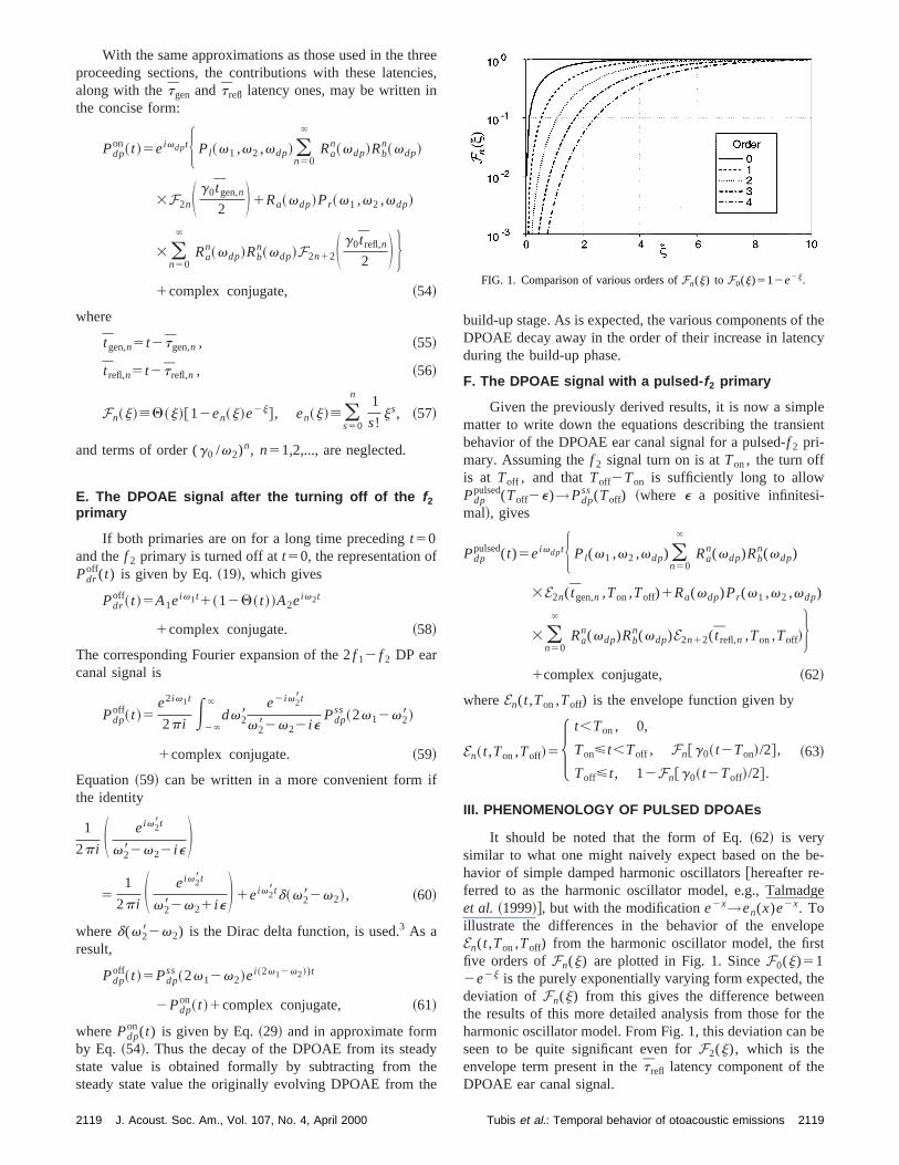
Fn~j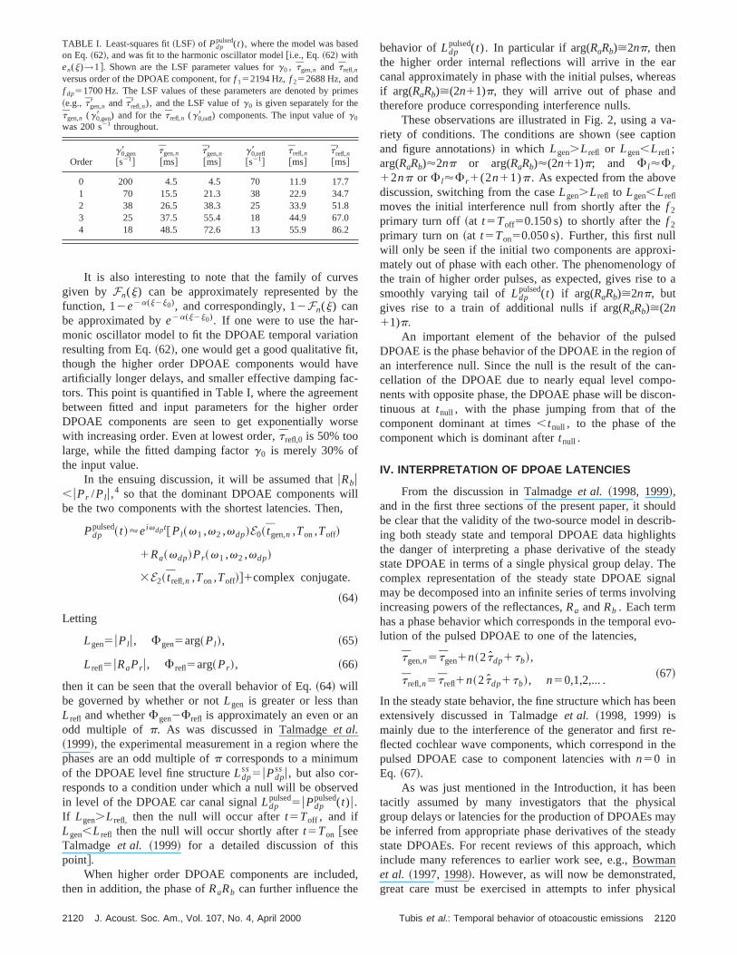
eshe
-n
t,vcenders
ill,
n
th
e
s
ed
areas
va-
e
li-
y ofto a
edofn-o-on-e
uldib-htsadyhenaling
evo-
een
re-the
enicalayadyichan
d,ical
d
im
It is also interesting to note that the family of curvgiven by Fn(j) can be approximately represented by tfunction, 12e2a(j2j0), and correspondingly, 12Fn(j) canbe approximated bye2a(j2j0). If one were to use the harmonic oscillator model to fit the DPOAE temporal variatioresulting from Eq.~62!, one would get a good qualitative fithough the higher order DPOAE components would haartificially longer delays, and smaller effective damping fators. This point is quantified in Table I, where the agreembetween fitted and input parameters for the higher orDPOAE components are seen to get exponentially wowith increasing order. Even at lowest order,t refl,0 is 50% toolarge, while the fitted damping factorg0 is merely 30% ofthe input value.
In the ensuing discussion, it will be assumed thatuRbu,uPr /Pl u,
4 so that the dominant DPOAE components wbe the two components with the shortest latencies. Then
Pdppulsed~ t !'eivdpt@Pl~v1 ,v2 ,vdp!E0~ tgen,n ,Ton,Toff!
1Ra~vdp!Pr~v1 ,v2 ,vdp!
3E2~ t refl,n ,Ton,Toff!#1complex conjugate.
~64!
Letting
Lgen5uPl u, Fgen5arg~Pl !, ~65!
L refl5uRaPr u, F refl5arg~Pr !, ~66!
then it can be seen that the overall behavior of Eq.~64! willbe governed by whether or notLgen is greater or less thanL refl and whetherFgen2Frefl is approximately an even or aodd multiple of p. As was discussed in Talmadgeet al.~1999!, the experimental measurement in a region wherephases are an odd multiple ofp corresponds to a minimumof the DPOAE level fine structureLdp
ss5uPdpssu, but also cor-
responds to a condition under which a null will be observin level of the DPOAE car canal signalLdp
pulsed5uPdppulsed(t)u.
If Lgen.L refl, then the null will occur aftert5Toff , and ifLgen,L refl then the null will occur shortly aftert5Ton @seeTalmadgeet al. ~1999! for a detailed discussion of thipoint#.
When higher order DPOAE components are includthen in addition, the phase ofRaRb can further influence the
TABLE I. Least-squares fit~LSF! of Pdppulsed(t), where the model was base
on Eq.~62!, and was fit to the harmonic oscillator [email protected]., Eq.~62! withen(j)→1#. Shown are the LSF parameter values forg0 , tgen,n and t refl,n
versus order of the DPOAE component, forf 152194 Hz, f 252688 Hz, andf dp51700 Hz. The LSF values of these parameters are denoted by pr~e.g., tgen,n8 and t refl,n8 ), and the LSF value ofg0 is given separately for thetgen,n (g0,gen8 ) and for thet refl,n (g0,refl8 ) components. The input value ofg0
was 200 s21 throughout.
Orderg0,gen8@s21#
tgen,n
@ms#tgen,n8@ms#
g0,refl8@s21#
t refl,n
@ms#t refl,n8@ms#
0 200 4.5 4.5 70 11.9 17.71 70 15.5 21.3 38 22.9 34.72 38 26.5 38.3 25 33.9 51.83 25 37.5 55.4 18 44.9 67.04 18 48.5 72.6 13 55.9 86.2
2120 J. Acoust. Soc. Am., Vol. 107, No. 4, April 2000
e-tre
e
d
,
behavior ofLdppulsed(t). In particular if arg(RaRb)>2np, then
the higher order internal reflections will arrive in the ecanal approximately in phase with the initial pulses, wherif arg(RaRb)>(2n11)p, they will arrive out of phase andtherefore produce corresponding interference nulls.
These observations are illustrated in Fig. 2, using ariety of conditions. The conditions are shown~see captionand figure annotations! in which Lgen.L refl or Lgen,L refl ;arg(RaRb)'2np or arg(RaRb)'(2n11)p; and F l'F r
12np or F l'F r1(2n11)p. As expected from the abovdiscussion, switching from the caseLgen.L refl to Lgen,L refl
moves the initial interference null from shortly after thef 2
primary turn off ~at t5Toff50.150 s) to shortly after thef 2
primary turn on~at t5Ton50.050 s). Further, this first nulwill only be seen if the initial two components are approxmately out of phase with each other. The phenomenologthe train of higher order pulses, as expected, gives risesmoothly varying tail ofLdp
pulsed(t) if arg(RaRb)>2np, butgives rise to a train of additional nulls if arg(RaRb)>(2n11)p.
An important element of the behavior of the pulsDPOAE is the phase behavior of the DPOAE in the regionan interference null. Since the null is the result of the cacellation of the DPOAE due to nearly equal level compnents with opposite phase, the DPOAE phase will be disctinuous at tnull , with the phase jumping from that of thcomponent dominant at times,tnull , to the phase of thecomponent which is dominant aftertnull .
IV. INTERPRETATION OF DPOAE LATENCIES
From the discussion in Talmadgeet al. ~1998, 1999!,and in the first three sections of the present paper, it shobe clear that the validity of the two-source model in descring both steady state and temporal DPOAE data highligthe danger of interpreting a phase derivative of the stestate DPOAE in terms of a single physical group delay. Tcomplex representation of the steady state DPOAE sigmay be decomposed into an infinite series of terms involvincreasing powers of the reflectances,Ra andRb . Each termhas a phase behavior which corresponds in the temporallution of the pulsed DPOAE to one of the latencies,
tgen,n5 tgen1n~2tdp1tb!,~67!
t refl,n5 t refl1n~2tdp1tb!, n50,1,2,... .
In the steady state behavior, the fine structure which has bextensively discussed in Talmadgeet al. ~1998, 1999! ismainly due to the interference of the generator and firstflected cochlear wave components, which correspond inpulsed DPOAE case to component latencies withn50 inEq. ~67!.
As was just mentioned in the Introduction, it has betacitly assumed by many investigators that the physgroup delays or latencies for the production of DPOAEs mbe inferred from appropriate phase derivatives of the stestate DPOAEs. For recent reviews of this approach, whinclude many references to earlier work see, e.g., Bowmet al. ~1997, 1998!. However, as will now be demonstrategreat care must be exercised in attempts to infer phys
es
2120Tubis et al.: Temporal behavior of otoacoustic emissions
s
FIG. 2. Model calculations showing the main behaviors that are predicted using Eq.~54!. In these figures, thef 2 primary is assumed to be pulsed from 50 mto 150 ms, withf 152194 Hz, f 252688 Hz, andf dp51700 Hz. For each panel, the conditions are shown both wherePl andRaPr ‘‘add’’ ~dark lines; e.g.,they constructivelyinterfere! and ‘‘subtract’’ ~gray lines; e.g., theydestructivelyinterfere!.r
avanavThp-;
ate-
group delays from phase derivatives of the steady statesponses, even in the case ofRa50, for which there is only asingle generation region.
The integral expression for thephysical group delaytgen, obtained from Eqs.~25!, ~26!, ~31!, and~33!, is
tgen5E0
x~v2!dx
]k~x,v2!
]v21E
0
x~v2!dx
]k~x,vdp!
]~vdp!, ~68!
where the first term is the group delay for the cochlear wtravel from the cochlear base to the generation region,the second is the group delay for the DP cochlear wave trfrom the generation region back to the cochlear base.integrations of Eq.~68! may be performed by assuming aproximate scale invariance~e.g., Zweig and Shera, 1995Talmadgeet al., 1998, 1999! in the form
k~x,v28!5k~v28/v~x!!, ~69!
where
v~x!'v0ce2kvx, ~70!
which gives
]k~x,v28!
]v285
1
kvv28
]k~x,v28!
]x. ~71!
Then
2121 J. Acoust. Soc. Am., Vol. 107, No. 4, April 2000
e-
edele
tgen'1
kvv2~k~ x~v2!,v2!2k~0,v2!!
11
kv~vdp!~k~ x~v2!,vdp!2k~0,vdp!!
'k
kvv21
k~ x~v2!,vdp!
kv~vdp!, ~72!
wherek is the wave number in the peak activity region~Tal-madgeet al., 1998; Zweig and Shera, 1995!, and it has beenassumed that
k~0,v2!!k~ x2~v2!,v2!, ~73!
k~0,vdp!!k~ x2~v2!,vdp!. ~74!
Equation~72! can be further simplified if it is assumed thx(v2) corresponds to the long-wavelength region for frquencyvdp . Then
k~ x~v2!,vdp!'k0
vdp
v2, ~75!
wherek0 is a constant defined in Eq.~12!. In summary,
tgen'k1k0
kvv2. ~76!
2121Tubis et al.: Temporal behavior of otoacoustic emissions

d
-
e
-
ade
ee
ons
tal,
the
-
iva-alonsa,her
qs.of
-e
ys
ed
to
As
onuplyre.
in
Latencies for the 2f 12 f 2 DPOAE have been associatewith the so-calledf 1- and f 2-sweep phase derivatives~e.g.,Kimberley et al., 1993; O’Mahoney and Kemp, 1995; Moulin and Kemp, 1996a, b; Bowmanet al., 1997, 1998;Schneideret al., 1999!
t f 22sweep[2S ]
]vdpwgen~v1 ,v2 ,vdp! D
v1
5S ]
]v2wgen~v1 ,v2 ,vdp! D
v1
~77!
and
t f 12sweep[2S ]
]vdpwgen~v1 ,v2 ,vdp! D
v2
521
2 S ]
]v1wgen~v1 ,v2 ,vdp! D
v2
, ~78!
where wgen(v1 ,v2 ,vdp) is the approximate phase of thgenerator-site component of the steady state DPOAE.
The phase derivativet f 22sweepis usually associated withthe shortest latency 2f 12 f 2 DPOAE component for the experimental conditions~steady statef 1 primary, pulsed-f 2 pri-mary! assumed in this paper. The phase derivativet f 12sweep
is associated with the case in which the roles off 1 and f 2 areinterchanged.
If the approximate expression,
wgen~v1 ,v2 ,vdp!52E0
x~v2!dx@2k~x,v1!
2k~x,v2!1k~x,vdp!#, ~79!
obtained from Eqs.~2! through ~14!, is used for the steadystate DPOAE phase whenRa50, it follows that
t f 22sweep5F ]
]v2wgen~v1 ,v2 ,vdp!G
v1
'2
kvv2k~ x~v2!,v1!1
2v1k~ x~v2!,vdp!
kvv2vdp
'4v1k0
kvv22 , ~80!
and
t f 12sweep521
2 F ]
]v1wgen~v1 ,v2 ,vdp!G
v2
'2k0
kvv2~81!
from an analysis based on the assumption of approximscale invariance which largely parallels the calculationsscribed by Eqs.~68!–~76!. It is thus seen thatt f 22sweep@seeEq. ~80!# is substantially different from the physical timdelay, tnl @see Eq.~76!#, even though both delays do havthe property of decreasing with increasingv2 ~for fixed v1).
2122 J. Acoust. Soc. Am., Vol. 107, No. 4, April 2000
te-
It is interesting to note that the approximate expressiobtained fort f 12sweepand t f 22sweepimply that
t f 22sweep
t f 12sweep'
2v1
v2, ~82!
a result that may be useful in interpreting the experimenfinding ~e.g., Kimberleyet al., 1993; O’Mahoney and Kemp1995; Moulin and Kemp, 1996a, b; Bowmanet al., 1997,1998; Schneideret al., 1999!; and references cited therein!that f 22sweep group delays tend to be larger thanf 12sweepdelays. It should be stressed that in obtaining this result,contribution to the phase fromDsm(x,v2) in Eq. ~4! hasbeen neglected.5 This contribution is connected with the socalled ‘‘filter build-up time,’’ which Bowmanet al. ~1998!associate with theentire difference betweent f 22sweep andt f 12sweep. The various issues concerning the phase dertives in relation to the filter build-up time and the physictime delays in pulsed DPOAEs, and comparisons of relatisuch as Eq.~82! with results derived from experimental datwill be addressed more carefully and extensively in anotpaper.
It is also instructive to compare the latencies from E~80! and~81! to the latency associated with the travel timea wave packet of frequencyv2 from the base to its tonotopicposition, x2 . The travel time of a traveling wave of frequencyv from the base tox(v) can be evaluated using thassumption of scale invariance@see, e.g., Talmadgeet al.~1998!#,
t~v!5E0
x~v!dx8
]k~x8,v!
]v
>1
kvv E0
x~v!dx8
]k~x8,v!
]x85
k
kvv, ~83!
so that t25 k/kvv2 . From swept2f 1 measurements@Tal-madgeet al. ~1998!#, k'3.6k0 , which gives
t f 12sweep'0.6t2 , t f 22sweep'1.1v1
v2t2 ,
~84!tfixed-ratio'0, tgen'1.3t2 ,
where the group delay for sweeping 2f 12 f 2 while fixing theratio f 2 / f 1 ~i.e., the ‘‘fixed-ratio’’ paradigm! has also beenincluded for comparison. None of the conventional delacorrespond tot2 , although t f 22sweep't2 for v2 /v1>1.2.An important implication of this result is that the measurt f 22sweepgroup delay should be a function ofv2 /v1 .
An even larger problem is encountered in attemptingassociate the group delay witht2 when the DPOAE reflec-tion site component is either comparable or dominant.was discussed in Talmadgeet al. ~1999!, the presence of twoDPOAE components with different phase dependenciesthe frequencies involved implies that there will be a grodelay fine structure, which will in general either strongcorrelate with or anti-correlate with the level fine structuWhen significant group delay fine structure is present,
2122Tubis et al.: Temporal behavior of otoacoustic emissions

thro
iteouor
eth
ue
al
n
r
tenaearan
nsie
oe
d
lo
se
c-
ofviorby
ed. 1der-nic
s-re-
areonevene,ichhis
p-od
dtor
inglebethe
arewn
of
s ofex-ex-
e-
itongere-D
terms of group delays for wave packet travel betweencochlear base and the DP generation region is clearly plematic.
The ‘‘worst case’’ scenario is when the reflection scomponent is dominant. For this case, the equivalent grdelays can be computed using the phase equation csponding to Eq.~79!:
w refl~v1 ,v2 ,vdp!52E0
x~v2!dx@2k~x,v1!2k~x,v2!
2k~x,vdp!#22k
kvlogS vdp
v0cD , ~85!
where w refl(v1 ,v2 ,vdp) is the approximate phase of threflection-site component of the steady state DPOAE and(2k/kv)log(vdp/v0c) term is the approximate phase shift dto the reflection of the DPOAE from its best place~e.g.,Shera and Zweig, 1993; Zweig and Shera, 1995; seeTalmadge and Tubis, 1993; Talmadgeet al., 1998!. Thegroup delays associated with Eq.~85! are
t@refl# f 12sweep5t@refl] f 22sweep
5 t[refl#fixed-ratio52k
kvvdp52tdp , ~86!
where Eq.~83! has been used in obtaining this result.Finally, if t2 can be measured via some other mea
~such as TEOAE measurements!, then, sincek is knownfrom measurements of the spacing of fine structure, themaining uncertain parameterk0 can be determined:
k0'S tgen
t221D k. ~87!
The inter-relationship given between the various parameof the cochlear model, which result from comparing differeOAE fine structures and different DPOAE paradigms, mprovide an important test of the theoretical framework givin Talmadgeet al. ~1998! as utilized here, as the cochlemodels and theoretical formalism continue to be refinedas the experimental data continue to improve.
V. SUMMARY AND CONCLUSIONS
Approximate expressions@Eqs.~54! and~61!# have beenderived for the explicit time dependence of the 2f 12 f 2
DPOAE under conditions of a steady statef 1 primary and anf 2 primary which is turned on and off. The approximatiomade were sufficient to allow the evaluation of the Fourintegral for the time dependence by use of the calculusresidues. Major simplifications were introduced by the nglect of the complications from~1! branch cuts associatewith the v28 dependence in Eqs.~10!–~12!, ~2! time-delayedstiffness terms in the determination of the complexv28 zeroesof Dsm(x,v28), and~3! the continuous character~x dependen-cies! of the latencies of the various group delay terms~seeSec. II B!.
On the basis of some general notions about group veity and group delay~e.g., Lighthill, 1978!, most of the tem-poral details of the simplified expressions could, of cour
2123 J. Acoust. Soc. Am., Vol. 107, No. 4, April 2000
eb-
pre-
e
so
s
e-
rstyn
d
rf-
c-
,
have been written down intuitively. The fact that the charateristic time for the transient build-up~or decay! of theDPOAE components of various latencies is 2/g0 is also ex-pected on the basis of the well-known dynamic propertiessimple damped harmonic oscillators. However, the behaof the envelope of the DPOAE transient, as determinedthis analysis, differs in important ways from that expectfrom the harmonic oscillator model, as is illustrated by Figand by Table I. As shown in this table, even the lowest or~shortest latency! reflected DPOAE component differs significantly from that expected on the basis of the harmooscillator model.
Most of the transient DPOAE phenomenology illutrated by Fig. 2 have been experimentally observed andported on in Talmadgeet al. ~1999!. Included in that paperare measurements in which the reflected componentsmodified by the placement of an external suppressing tnear in frequency to the DPOAE. In this way, the relatilevels of the DPOAEs can be modified. When this is dothe pulsed DPOAE level and phase vary in a manner whis qualitatively consistent with the theory presented in tpaper.
A future direction of research will be to fit Eq.~64!directly to experimental measurement. If the level of aproximation given by this paper is sufficient, this methcould yield direct measurements of the values ofRaRb , Pl ,and RaPr as a function of level, DPOAE frequency, anprimary frequency ratio, as well the effective damping facg0/2 and the various latencies,tgen,n and t refl,n . Because themeasurements are based on measurements at a sDPOAE frequency, the analysis of this class of data maymore robust than methods based on measurement ofsteady state DPOAE behavior across frequency.
The exercise of determining the approximations thatneeded to to obtain these results is also useful in its oright. In particular, it should prompt further investigationsthe extent to which the simple behaviors in Eqs.~54! and~61! describe actual experimental data and/or the resulttime-domain cochlear model simulations. Some of theperimental implications of the results have already beenplored in Talmadgeet al. ~1999!. It would also be interestingto apply the formalism to more realistic two- and thredimensional cochlear models.
ACKNOWLEDGMENTS
We wish to thank Professor Glenis R. Long, SumDhar, and Lauren A. Shaffer for many useful discussionsthe topies of this paper. We would also like to acknowledthe careful reviews by Chris Shera and an anonymousviewer. This research was supported in part by NIH/NICGrants No. R01 DC00307 and No. R29 DC03094.
2123Tubis et al.: Temporal behavior of otoacoustic emissions

nta
nd
c
ase
n-
r,
-
nt
y
y
f
at
t
li-
d
d
d
t-
d
tshe
n
n
l
l
l
l
ts
APPENDIX A. FREQUENTLY USED SYMBOLS ANDTHEIR MEANING
Mathematical symbols frequently used in this study atheir meaning are summarized below. For additional notional definitions, see also Talmadgeet al. ~1998!. In casesfor which the symbol has a defining equation, its correspoing equation number is also included.
Operators
arg(z) phase ofzuzu magnitude ofzA denotes a quantity evaluated at the a
tivity pattern maximumA denotes that the quantityA contains a
random componentA denotes an effective value, usually
the result of combining several morfundamental quantities
Independent variables and physical quantities
f frequency with units of inverselength.
P pressuret timex position along basilar membrane (x
50 corresponds to base!l wavelengthv angular frequency (2p3 f )w phaseF total or ‘‘unwrapped’’ phasej linear displacement, also dimensio
less variablee a positive infinitesimal
Constants
A1,2 steady state amplitudes of lowehigher frequency primaries
eg nonlinear damping strengthf 1,2 frequencies of lower, higher fre
quency primariesf dp 2 f 121 f 2 ; frequency of DP under
considerationk wave number~2p/l!, also used to sig-
nify quantitiesk0 geometrical wave number consta
@see Talmadgeet al. ~1998!#kv exponential constant for frequenc
mapk real part of wave number at activit
pattern maximumTon time of f 2 primary signal turn onToff time of f 2 primary signal turn offv0c,1c exponential coefficient and offset o
frequency map
Functions
Q(x) Heaviside Theta function@Eq. ~18!#en(j) truncated exponential series@Eq. ~57!#
2124 J. Acoust. Soc. Am., Vol. 107, No. 4, April 2000
d-
-
-
Fn(j) DPOAE transient function for af 2
primary turned on att50 @Eq. ~57!#En(t,Ton,Toff) envelope function for a pulsed-f 2 pri-
mary @Eq. ~63!#W0(v) the Wronskian ofc r ,l(x,v) @W0(v)
5c r(x,v)c l8(x,v)2c r8(x,v)c l(x,v)#
Pressure
Pdrss(t) steady state ‘‘calibrated’’ driving
pressure@Eq. ~1!#Pdr
on(t) a driving pressure that is turned ont50 @Eq. ~17!#
Pdroff(t) a driving pressure that is turned off a
t50 @Eq. ~19!#Pdp
ss(v1 ,v2 ,vdp) steady state DPOAE ear canal amptude @Eq. ~2!#
Pdpon(t) ear canal DPOAE level associate
with a turn on of thef 2 primary at t50 @Eq. ~20!#
Pdpoff(t) ear canal DPOAE level associate
with a turn off of thef 2 primary att50 @Eq. ~59!#
Pdpgen(t) ear canal DPOAE level associate
with a turn on of thef 2 primary at t50, for the initial basally movingcomponent that was directly transmited to the ear canal@Eq. ~43!#
Pdprefl(t) ear canal DPOAE level associate
with a turn on of thef 2 primary at t50, for the initial apically movingcomponent that was reflected at ibest place, and then transmitted to tear canal@Eq. ~45!#
Pl(v1 ,v2 ,vdp) ear canal DPOAE amplitude due to ainitially generated basally moving DPcomponent@Eq. ~3!#
Ra(vdp)3Pr(v1 ,v2 ,vdp) ear canal DPOAE amplitude due to a
initially generated apically movingDP component@Eq. ~3!#
Latencies
t(x,v) travel time of a wave packet of centrafrequencyv from the base to positionx @Eq. ~26!#
t2(x) travel time of a wave packet of centrafrequencyv2 from the base to posi-tion x @Eq. ~25!#
t2 travel time of a wave packet of centrafrequency v2 from the base to itstonotopic location@Eq. ~33!#
tdp(x) travel time of a wave packet of centrafrequencyvdp from the base to posi-tion x @Eq. ~28!#
tdp travel time of anvdp wave packet ofcentral frequency from the base to itonotopic location@Eq. ~33!#
2124Tubis et al.: Temporal behavior of otoacoustic emissions
-th
e
-thl,aln
-thlhe-
-thl,al
ed
tgen latency of the DPOAE transient response associated with a change inf 2 signal component, for the DPOAEcomponent initially produced at thgenerator site@Eq. ~31!#
t refl latency of the DPOAE transient response associated with a change inf 2 signal component, for the initiaapically moving DP componentwhich is transmitted to the ear canafter being reflected from the regioof the DP best place@Eq. ~32!#
tgen,n latency of the DPOAE transient response associated with a change inf 2 signal component, for the initiabasally moving DP component, whicis transmitted to the ear canal after bing multiply internally reflectedntimes @Eq. ~34!#
t refl,n latency of the DPOAE transient response associated with a change inf 2 signal component, for the initiaapically moving DP componentwhich is transmitted to the ear canafter being multiply internally re-flectedn times @Eq. ~35!#
ta
2125 J. Acoust. Soc. Am., Vol. 107, No. 4, April 2000
e
e
e
e
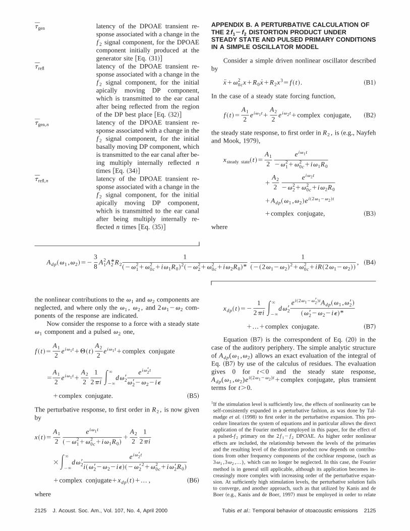
APPENDIX B. A PERTURBATIVE CALCULATION OFTHE 2f 1Àf 2 DISTORTION PRODUCT UNDERSTEADY STATE AND PULSED PRIMARY CONDITIONSIN A SIMPLE OSCILLATOR MODEL
Consider a simple driven nonlinear oscillator describby
x1v0c2 x1R0x1R2x35 f ~ t !. ~B1!
In the case of a steady state forcing function,
f ~ t !5A1
2eiv1t1
A2
2eiv2t1complex conjugate, ~B2!
the steady state response, to first order inR2 , is ~e.g., Nayfehand Mook, 1979!,
xsteady state~ t !5A1
2
eiv1t
2v121v0c
2 1 iv1R0
1A2
2
eiv2t
2v221v0c
2 1 iv2R0
1Adp~v1 ,v2!ei ~2v12v2!t
1complex conjugate, ~B3!
where
Adp~v1 ,v2!523
8A1
2A2* R2
1
~2v121v0c
2 1 iv1R0!2~2v221v0c
2 1 iv2R0!*
1
~2~2v12v2!21v0c2 1 iR~2v12v2!!
, ~B4!
ureofione,t
beTal-
o-irectt ofrries
ibu-
rierin-an-ilsd dee
the nonlinear contributions to thev1 andv2 components areneglected, and where only thev1 , v2 , and 2v12v2 com-ponents of the response are indicated.
Now consider the response to a force with a steady sv1 component and a pulsedv2 one,
f ~ t !5A1
2eiv1t1Q~ t !
A2
2eiv1t1complex conjugate
5A1
2eiv1t1
A2
2
1
2p i E2`
`
dv28eiv28t
v282v22 i e
1complex conjugate. ~B5!
The perturbative response, to first order inR2 , is now givenby
x~ t !5A1
2
eiv1t
~2v121v0c
2 1 iv1R0!1
A2
2
1
2p i
3E2`
`
dv28eiv28t
i ~v282v22 i e!~2v2821v0c
2 1 iv28R0!
1complex conjugate1xdp~ t !1... , ~B6!
where
te
xdp~ t !521
2p i E2`
`
dv28ei ~2v12v28!tAdp~v1 ,v28!
~v282v22 i e!*
1...1complex conjugate. ~B7!
Equation ~B7! is the correspondent of Eq.~20! in thecase of the auditory periphery. The simple analytic structof Adp(v1 ,v2) allows an exact evaluation of the integralEq. ~B7! by use of the calculus of residues. The evaluatgives 0 for t,0 and the steady state responsAdp(v1 ,v2)ei (2v12v2)t1complex conjugate, plus transienterms fort.0.
1If the stimulation level is sufficiently low, the effects of nonlinearity canself-consistently expanded in a perturbative fashion, as was done bymadgeet al. ~1998! to first order in the perturbative expansion. This prcedure linearizes the system of equations and in particular allows the dapplication of the Fourier method employed in this paper, for the effeca pulsed-f 2 primary on the 2f 12 f 2 DPOAE. As higher order nonlineaeffects are included, the relationship between the levels of the primaand the resulting level of the distortion product now depends on contrtions from other frequency components of the cochlear response,~such as3v1 ,3v2 ,...), which can no longer be neglected. In this case, the Foumethod is in general still applicable, although its application becomescreasingly more complex with increasing order of the perturbative expsion. At sufficiently high stimulation levels, the perturbative solution fato converge, and another approach, such as that utilized by Kanis anBoer ~e.g., Kanis and de Boer, 1997! must be employed in order to relat
2125Tubis et al.: Temporal behavior of otoacoustic emissions

m
r teror
ecf tdi
on
-pa
beco
5
b
-
P.
m
P.onr-
o
tom
c
f
m.
.
J.
icst.
ion
-
-
ry-
re-rela-
s
-
tics,’’
tor-
st.
-
-
d
l
l
n
d
ure
the primary pressure levels to the resulting DPOAE pressure. In this lithe Fourier method utilized in this paper is no longer applicable.
2In practice, it is necessary to digitally filter the ear canal signal in ordeextract the DPOAE waveform. Typically this filter has a width no largthan 300 Hz, which imposes a temporal smearing of the DPOAE wavefon the order of 3 ms. Even at moderately low frequencies~e.g., f51000 Hz), the delay associated with the slow stiffness feedback;1.75/1000 Hz51.75 ms. Consequently, except at low frequencies, direct effof the stiffness feedback may be safely neglected, and the only effect ostiffness feedback term is to shift the place-frequency map and to mothe effective value ofg0 .
3This identity can be derived by comparing Eqs.~17! and~19!, which gives
1
2pi E2`
`
dv28S eiv28t
v282v22ie2
eiv28t
v282v21ieD5eiv2t@Q~t!112Q~t!#5eiv2t.
Comparison of the left- and right-hand sides of this equation gives
1
2pi E2`
dv28S eiv28t
v282v22ie2
eiv28t
v282v21ieD5E
2`
`
dv28eiv28td~v282v2!.
An alternative way of proving this result is to note that
lime→01
1
2p i S 1
v282v22 i e2
1
v282v21 i e D 51
plim
e→01
F e
e21~v282v2!2Gis a well known representation ofd(v282v2) ~e.g., Arfken and Weber,1995, p. 83!.
4To understand this caveat, consider the leading terms in the expansiEq. ~3! under the assumption thatuRau!1:
Pdpss5PlF11SPr
Pl2RbDRa1...G.
This expansion follows from the fact thatuRbu<1, and the frequency dependence of the various terms has been ignored for brevity. In this exsion. Pdp
ss will be dominated by thePl and RaPr terms if uRbu,uPr /Pl u.The effect ofuRbu.uPr /Pl u will be explored in a future paper.
5It might be suggested that neglect of the ‘‘filter build-up time’’ canjustified only in a scale-invariant cochlear model. However, even inchlear models with a significant scale-invariance violations~e.g., one whichhas theQ of the activity pattern maximum varying from 15 at the base toat the apex!, it turns out that the corresponding variations inDsm(x,v) arestill very small over the region of the activity pattern maximum, and cansafely neglected.
Arfken, G. B., and Weber, H. J.~1995!. Mathematical Methods for Physicists, 4th ed.~Academic, San Diego!.
Bowman, D. M., Brown, D. K., Eggermont, J. J., and Kimberley, B.~1997!. ‘‘The effect of sound intensity onf 1-sweep andf 2-sweep distor-tion product otoacoustic emissions phase delay estimates in huadults,’’ J. Acoust. Soc. Am.101, 1550–1559.
Bowman, D. M., Eggermont, J. J., Brown, D. K., and Kimberly, B.~1998!. ‘‘Estimating cochlear filter response properties from distortiproduct otoacoustic emission~DPOAE! phase delay measurements in nomal hearing human adults,’’ Hear. Res.119, 14–26.
Brown, A. M., Gaskill, S. A., and Williams, D. M.~1992!. ‘‘Mechanicalfiltering of sound in the inner ear,’’ Proc. R. Soc. London, Ser. B250,29–34.
Brown, A. M., Harris, F. P., and Beveridge, H. A.~1996!. ‘‘Two sources ofacoustic distortion products from the human cochlea,’’ J. Acoust. SAm. 100, 3260–3267.
Brown, A. M., Gaskill, S. A., Carlyon, R. P., and Williams, D. M.~1993!.‘‘Acoustic distortion as a measure of frequency selectivity: relationpsychophysical equivalent rectangular bandwidth,’’ J. Acoust. Soc. A93, 3291–3297.
Gaskill, S. A., and Brown, A. M.~1996!. ‘‘Suppression of human acoustidistortion product: Dual origin of 2f 12 f 2 ,’’ J. Acoust. Soc. Am.100,3268–3274.
Hall, J. L. ~1974!. ‘‘Two-tone distortion products in a nonlinear model othe basilar membrane,’’ J. Acoust. Soc. Am.56, 1818–1828.
He, N.-J., and Schmiedt, R. A.~1993!. ‘‘Fine structure of the 2f 12 f 2 acous-tic distortion product: Changes with primary level,’’ J. Acoust. Soc. A94, 2659–2669.
He, N.-J., and Schmiedt, R. A.~1996!. ‘‘Effects of aging on the fine struc-ture of the 2f (1)2 f (2) acoustic distortion product,’’ J. Acoust. Soc. Am99, 1012–1015.
2126 J. Acoust. Soc. Am., Vol. 107, No. 4, April 2000
it,
o
m
tshefy
of
n-
-
e
an
c.
.
He, N.-J., and Schmiedt, R. A.~1997!. ‘‘Fine structure of the 2f 12 f 2 acous-tic distortion product: Effects on primary level and frequency ration,’’Acoust. Soc. Am.101, 3554–3565.
Kanis, L. J., and de Boer, E.~1997!. ‘‘Frequency dependence of acoustdistortion products in a locally active model of the cochlea,’’ J. AcouSoc. Am.101, 1527–1531.
Kemp, D. T., and Brown, A. M.~1983!. ‘‘An integrated view of the cochlearmechanical nonlinearities observable in the ear canal,’’ inMechanics ofHearing, edited by E. de Boer and M. A. Viergever~Martinus Nijhoff,The Hague, The Netherlands!, pp. 75–82.
Kimberley, B. P., Brown, D. K., and Eggermont, J. J.~1993!. ‘‘Measuringhuman cochlear traveling wave delay using distortion product emissphase responses,’’ J. Acoust. Soc. Am.94, 1343–1350.
Kummer, P., Janssen, T., and Arnold, W.~1995!. ‘‘Suppression tuning char-acteristics of the 2f 12 f 2 distortion product otoacoustic emission in humans,’’ J. Acoust. Soc. Am.98, 197–210.
Lighthill, J. ~1978!. Waves in Fluids~Cambridge University Press, Cambridge!, pp. 237–244.
Martin, G. K., Jassir, D., Stagner, B. B., Whitehead, M. L., and LonsbuMartin, B. L. ~1998!. ‘‘Locus of generation for the 2f 12 f 2 vs 2f 22 f 1distortion-product otoacoustic emissions in normal-hearing humansvealed by suppression tuning, onset latencies, and amplitude cortions,’’ J. Acoust. Soc. Am.103, 1957–1971.
Mathews, J., and Walker, R.~1964!. Mathematical Methods of Physic~Benjamin, New York!.
Mills, D. M. ~1997!. ‘‘Interpretation of distortion product otoacoustic emission measurements: I. Two stimulus tones,’’ J. Acoust. Soc. Am.102,413–429.
Moulin, A., and Kemp, D. T.~1996a!. ‘‘Multicomponent acoustic distortionproduct otoacoustic emission phase in humans. I. General characterisJ. Acoust. Soc. Am.100, 1617–1639.
Moulin, A., and Kemp, D. T.~1996b!. ‘‘Multicomponent acoustic distortionproduct otoacoustic emission phase in humans. II. Implications for distion product generation,’’ J. Acoust. Soc. Am.100, 1640–1666.
Nayfeh, A. T., and Mook, D. T.~1979!. Nonlinear Oscillations~Wiley, NewYork!, Chap. 4.
O’Mahoney, C. F., and Kemp, D.~1995!. ‘‘Distortion product otoacousticemission delay measurement in humans,’’ J. Acoust. Soc. Am.97, 3721–3735.
Schneider, S., Prijs, V. F., and Schoonhoven, R.~1999!. ‘‘Group delays ofdistortion product otoacoustic emissions in the guinea pig,’’ J. AcouSoc. Am.105, 2722–2730.
Shera, C. A., and Zweig, G.~1992!. ‘‘Analyzing reverse middle-ear transmission: Noninvasivegedankenexperiments,’’ J. Acoust. Soc. Am.92,1371–1381.
Shera, C. A., and Zweig, G.~1993!. ‘‘Order from chaos: resolving the paradox of periodicity in evoked otoacoustic emission,’’ inBiophysics of HairCell Sensory Systems, edited by H. Duifhuis, J. W. Horst, P. van Dijk, anS. M. van Netten~World Scientific, Singapore!, pp. 54–63.
Stover, L. J., Neely, S. T., and Gorga, M. P.~1996!. ‘‘Latency and multiplesources of distortion product emissions,’’ J. Acoust. Soc. Am.99, 1016–1024.
Sun, X. M., Schmiedt, R. A., He, N.-J., and Lam, C. F.~1994a!. ‘‘Modelingthe fine structure of the 2f (1)2 f (2) acoustic distortion product. 1. Modedevelopment,’’ J. Acoust. Soc. Am.96, 2166–2174.
Sun, X. M., Schmiedt, R. A., He, N.-J., and Lam, C. F.~1994b!. ‘‘Modelingthe fine structure of the 2f (1)2 f (2) acoustic distortion product. 2. Modeevaluation,’’ J. Acoust. Soc. Am.96, 2175–2183.
Talmadge, C., and Tubis, A.~1993!. ‘‘On modeling the connection betweespontaneous and evoked otoacoustic emissions,’’ inBiophysics of HairCell Sensory Systems, edited by H. Duifhuis, J. W. Horst, P. van Dijk, anS. M. van Netten~World Scientific, Singapore!, pp. 25–32.
Talmadge, C., Tubis, A., Piskorski, P., and Long, G. R.~1997!. ‘‘Modelingotoacoustic emission fine structure,’’ inDiversity in Auditory Mechanics,edited by E. Lewis, G. Long, R. Lyon, P. Narins, and C. Steele~WorldScientific, Singapore!, pp. 462–471.
Talmadge, C. L., Long, G. R., Tubis, A., and Dhar, S.~1999!. ‘‘Experimen-tal confirmation of the two-source interference model for the fine structof distortion product otoacoustic emissions,’’ J. Acoust. Soc. Am.105,275–292.
2126Tubis et al.: Temporal behavior of otoacoustic emissions

’’
.
Talmadge, C. L., Tubis, A., Long, G. R., and Piskorski, P.~1998!. ‘‘Mod-eling otoacoustic emission and hearing threshold fine structures,Acoust. Soc. Am.104, 1517–1543.
Zweig, G. ~1991!. ‘‘Finding the impedance of the organ of Corti,’’ JAcoust. Soc. Am.89, 1229–1254.
2127 J. Acoust. Soc. Am., Vol. 107, No. 4, April 2000
J.Zweig, G., Lipes, R., and Pierce, J. R.~1976!. ‘‘The cochlear compromise,’’
J. Acoust. Soc. Am.59, 975–982.Zweig, G., and Shera, C. A.~1995!. ‘‘The origins of periodicity in the
spectrum of evoked otoacoustic emissions,’’ J. Acoust. Soc. Am.98,2018–2047.
2127Tubis et al.: Temporal behavior of otoacoustic emissions
Copyright © 2022 FDOKUMEN