Modeling and optimization of a 1 kWe HT-PEMFC-based micro-CHP residential system
lable at ScienceDirect
Energy 36 (2011) 993e1002
Contents lists avai
Energy
journal homepage: www.elsevier .com/locate/energy
Modeling and off-design performance of a 1 kWe HT-PEMFC(high temperature-proton exchange membrane fuel cell)-basedresidential micro-CHP (combined-heat-and-power) system forDanish single-family households
Alexandros Arsalis*, Mads P. Nielsen, Søren K. KærDepartment of Energy Technology, Aalborg University, Pontoppidanstræde 101, 9220 Aalborg Ø, Denmark
a r t i c l e i n f o
Article history:Received 10 May 2010Received in revised form25 November 2010Accepted 7 December 2010Available online 8 January 2011
Keywords:PBI membraneHT-PEMFC systemsMicro-CHPResidential systemsFuel processing
* Corresponding author. Tel.: þ45 9940 9240; fax:E-mail address: [email protected] (A. Arsalis).
0360-5442/$ e see front matter � 2010 Elsevier Ltd.doi:10.1016/j.energy.2010.12.009
a b s t r a c t
A novel proposal for the modeling and operation of a micro-CHP (combined-heat-and-power) residentialsystem based on HT-PEMFC (High Temperature-Proton Exchange Membrane Fuel Cell) technology isdescribed and analyzed to investigate its commercialization prospects. An HT-PEMFC operates atelevated temperatures, as compared to Nafion-based PEMFCs and therefore can be a significant candi-date for cogeneration residential systems. The proposed system can provide electric power, hot water,and space heating for a typical Danish single-family household. A complete fuel processing subsystem,with all necessary BOP (balance-of-plant) components, is modeled and coupled to the fuel cell stacksubsystem. The micro-CHP system is simulated in LabVIEW� environment to provide the ability of DataAcquisition of actual components and thereby more realistic design in the future. A part-load study hasbeen conducted to indicate performance characteristics at off-design conditions. The system is sized toprovide realistic dimensioning of the actual system.
� 2010 Elsevier Ltd. All rights reserved.
1. Introduction
Fuel cell-based stationary power generation offers a greatmarket opportunity, because the fuel cell technology is capable ofachieving higher efficiencies, with lower emissions as compared toconventional power systems [1e3]. Residential fuel cell systemscan be grid-interconnected to allow power flow from/to the grid asneeded. This design offers greater flexibility than a stand-alonesystem, and is very attractive if the incoming power is produced byrenewable energy sources, such as wind power [3,4]. This meansthat when cheap wind power can be produced, the fuel cell systemcan operate at a minimum load and therefore reduce the fuelconsumption. A fuel cell-based micro-CHP (Combined-Heat-and-Power) system converts on-site the chemical energy in a fuel, e.g.natural gas, into electrical power and heat, as required by thehousehold demand. The range of energy demand for a Danishhousehold in terms of electricity and heat is 0.5e5.0 kWe, and2e10 kWth, respectively. Therefore, for this system configuration,a fuel-processing unit must be coupled with the fuel cell stack, to
þ45 9815 1411.
All rights reserved.
allow conversion of natural gas to hydrogen. Several BOP (Balance-Of-Plant) components are needed for the controlling and smoothoperation of the system, while heat exchangers are necessary forthe thermal management of the system. The thermal managementof the system includes heating/cooling of components (e.g. steamreforming), and also heat recovery to satisfy the residential loadprofile (e.g. space heating).
The operating temperature in a fuel cell stack is considered animportant factor to the efficiency and the degradation of themembrane. High operating temperatures reduce the coolingrequirements, simplify water management and lessen contamina-tion problems. An HT-PEMFC (high temperature-proton exchangemembrane fuel cell) utilizes a PBI (Polybenzimidazole) membrane,operating at temperatures between 160 �C and 200 �C. An HT-PEMFC is therefore an ideal match for a micro-CHP system, becausenot only the rates of electrochemical kinetics are enhanced andwater management and cooling is simplified, but also useful wasteheat can be recovered, and lower quality reformed hydrogen maybe used as fuel [5]. However, the frequent changes of demand, interms of electrical power and/or heat, require operation in varyingpartial-load conditions. A simple and compact design, with efficientadaptability to load changes must be accomplished, which is vitalfor this type of application.
A. Arsalis et al. / Energy 36 (2011) 993e1002994
The Danish micro-CHP project is managed by a national cons-ortium consisting of nine Danish energy companies. The consor-tium combines all the competencies necessary to develop, test, anddemonstrate micro-CHP systems. The project cooperates witha wide range of political and specialist parties, such as the DanishEnergy Agency. It is also financially assisted by the Danish Ministryof Climate and Energy by 40% of the total cost of the project. It isscheduled to run from 2006 to 2012, and includes fuel cell systemsbased on three different technologies: LT-PEMFC (low temperature-proton exchange membrane fuel cell), HT-PEMFC and SOFC (SolidOxide Fuel Cell). It is divided into three phases, and two fuel typesare used: hydrogen and natural gas. The choice of fuel depends onthe fuel cell technology and its availability at the installation sites.A preliminary assumption concerning the operational control of thesystem, indicated that the electrical load must be fulfilled, but alsothe design should secure the right amount of heat will be availableon demand for the space heating and hot water loads. Further on,an auxiliary burner for peak production of thermal energy is underconsideration to be integrated to the end-user system [3,6].
TheHT-PEMFC-basedmicro-CHPunitsaredevelopedbyDanthermPower and operate on natural gas. Experimental tests, with purehydrogen fuel, showed start-up times of 30e60min,with an electricalefficiency of 40e58% (LHV (Lower Heating Value)-based). From theoperatingpointof thefinalizeddesign, anefficiencyof50% isexpected.Furtherexperimental testsandcalculations showedapotential systemefficiencyof85e90%(LHV-based) [6].A fastadaption to loadvariationswas also observed. In the first phase, Danish Micro Combined-Heat-and-Power developed micro-CHP unit prototypes with PEMFC andSOFC fuel cells. In thesecondphase, tenmicro-CHPunits arescheduled
Fig. 1. Schematic of the prop
to be installed and tested at selected consumer households in themunicipalities of Lolland and Sønderborg, Denmark. In the third andlast phase, micro-CHP systems will be installed and demonstrated ataround 100 households in the two aforementioned municipalities.This will allow the Danish micro-CHP system project to gather andanalyze realistic experiences related to installation, operationalprocedures,maintenance needs and also consumer satisfaction. Thesewill be used for further system improvement [6].
2. System layout
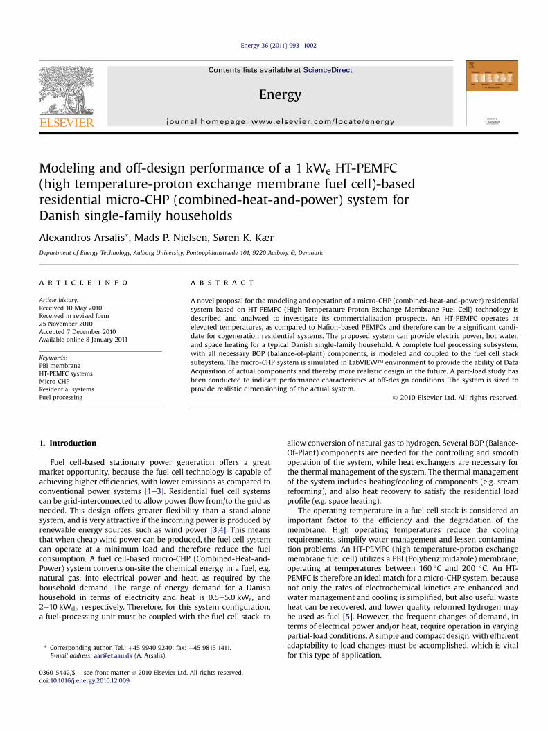
The proposed micro-CHP system, shown in Fig. 1, is modeled inLabVIEW� to provide easiness in user usage of the program, and toallow future experimental testing capabilities with Data Acquisitionhardware. Fig. 2, shows an indicative front panel of the fuel cell stacksubsystem. In order to synthesize and design the proposed micro-CHP system, the energy requirements for a representative residen-tial buildingmust be established. For the current research study, therepresentative residential building is a typical Danish single-familyhousehold (130 m2 house with four persons: two adults and twochildren). A micro-CHP unit of approximately 1 kWe is considered.The types of residential loads considered are the following:
(a) Electrical load;(b) Space heating load;(c) Hot water load.
Averaged daily power load curves for all three loads weremeasured for 25 houses at a 15 min average time segment [4]. For
osed micro-CHP system.

Fig. 2. LabVIEW front panel of the Fuel Cell Stack subVI.
A. Arsalis et al. / Energy 36 (2011) 993e1002 995
the purposes of this research study, the entire load profile, shown inTable 1, has been simplified into three time segments, i.e. winter,summer, and spring (autumn).
By observation, it is clear that the winter segment appears to bethe one with the most stringent for electrical and space heatingloads, while hot water load is most stringent during spring season.Therefore the system must be designed to fulfill the maximumwinter electrical load 0.95 kWe, since the proposed micro-CHPsystem assumes an electricity-led operation. It should be noted thatat short time segments the electrical power demand will exceed1 kWe. In this case, electrical power will be imported from the grid.On the other hand, the remaining heat load demand can be satisfiedwith external means, e.g. auxiliary burner. It should be noted thatthese are beyond the scope of this study, and only the percentage ofheating load fulfilled from the proposed system is analyzed.
The various efficiencies should be defined, before the modelingdetails are given in the next section. The cogeneration thermal effi-ciency isdefinedasthe ratioof theactualwasteheat recoveredbyheatexchangers IV, V, and VI and the chemical energy input to the system,
ðhthermalÞcogen: ¼�_QHEx
�cogen:
_mCH4;inLHVCH4
(1)
The corresponding electrical efficiency is defined as the ratio ofthe net electrical power output of the system divided by thechemical energy input to the system,
Table 1Mean residential load requirements for a typical Danish household.
Residential load type Time segment
Winter Summer Spring
Mean Max Mean Max Mean Max
Electrical load (We) 540 950 380 650 460 920Space heating load (Wth) 1450 1930 70 140 600 1070Hot water load (Wth) 330 1080 230 1420 310 1620
ðhelectricalÞnet ¼�_Welectrical
�net
_mCH4;inLHVCH4
(2)
The combined cogeneration system efficiency is defined as thesum of the net electrical power output of the system and the actualwaste heat recovered divided by the chemical energy input to thesystem,
�hsystem
�cogen:
¼�_Welectrical
�netþ
�_QHEx
�cogen:
_mCH4 ;inLHVCH4
(3)
3. Modeling of the micro-CHP system
The system is designed initially at nominal load to investigateoperating behavior and geometric analysis of the most importantsystem components. All necessary components/subsystems, withemphasis on the fuel processing subsystem, are modeled in detailbased on semi-empirical assumptions from the literature to allowa realistic analysis of the system parameters. Then the system issimulated at part-load conditions to investigate its behavior at off-design and the effects of an electricity-led operation on the totalheat load fulfillment. All the individual models are described in thissection in terms of input and output parameters and specificassumptions for every particular model under study are also given.
The operational principle of the proposed system, shown inFig. 1, is the following: Natural gas is desulfurized at an acceptablelevel; hydrogen sulfide content must be removed to values below1 ppm [7]. Water is pumped from the line into the steam generator,where it is superheated with flue gas exhausted by the shell-side ofthe SMR (steammethane reformer) reactor. Superheated steam andpreheated natural gas are mixed in the mixer, and then the steam-fuel mixture is fed to the tube-side of the SMR reactor. The inputs ofthe catalytic combustor are air, methane (necessary at start-up),and reformate fuel (depleted fuel from the anode of the fuel cell
A. Arsalis et al. / Energy 36 (2011) 993e1002996
stack). Its main purpose is to provide heat for the endothermicsteam methane reforming reaction.
In the SMR reactor, the reforming reaction takes place. It shouldbe noted that the SMR process is based on reaction kinetics, and ismodeled as a PFR (plug flow reactor) with the presence of a catalyst,with experimental data taken from [8]. In terms of heat exchanging,the SMR is modeled as a shell-and-tube heat exchanger, where theshell part carries the hot flue gas, and the tube part carries thevaporized methane-water mixture. The produced hydrogen-richsynthesis gas is mixed with water and enters the WGS (water gasshift) reactor, which is modeled similarly to the SMR. It serves asa reduction of the carbon monoxide content, which is converted tocarbon dioxide, into a tolerable level for the fuel cell stack. It alsocontributes in further hydrogen production.
The reformate fuel enters the anode side of the fuel cell stack,where a part of it is depleted and used in the combustor for theSMR reaction described above. In the cathode of the fuel cell stack,air enters and used for the fuel cell reaction converting thechemical energy of reformate and air into electricity. A by-productof this reaction is the hot mixture, which exits from the fuel cellstack. This mixture is used in a plate heat exchanger to satisfya part of the residential heat load. A part of the residential heatload is also satisfied by the exhausted flue gas at the naturalgas pre-heater. Flue-gas is then passed through open-loop andclosed-loop heat exchangers for water heating and space heating,respectively.
3.1. Fuel cell stack
The fuel cell stack model is based on [3,9]. Initially, the modelcalculates the required hydrogen feed based on the number of cellsspecified in the model. At part-load the model is modified to havethe feed reformate fuel (hydrogen-rich gas) as an input to themodel, in order to allow the calculation of power output at off-design conditions. Similarly, the current density is constant at full-load (0.2 cm2/A) and a calculated variable at part-load conditions.
The following assumptions were made:
� The model considers only the reaction of hydrogen withoxygen (air). All other substances are considered inactive.
� The reformate fuel after theWGS Reactor/Plate Heat Exchangerstage passes through a condenser/knock-out stage, where allthe water content in the fuel is removed. Nevertheless, somewater-content is considered because the moisture content inthe incoming air is included in the calculations.
� The temperature of the incoming reformate fuel is 160 �C,which is the fuel cell stack operating temperature.
� The cell active area is 49 cm2.� Heat losses are neglected in the calculations.
The ohmic and diffusion resistances are given by,
Rohmic ¼ �0:0001667Tcell þ 0:2289 (4)
Rdiff ¼ 0:4306� 0:0008203Tcell (5)
The anode and cathode overpotentials are given by,
ha ¼ RTcellaanodeF
arcsinh�
i2kehqH2
�(6)
hc ¼ RTcell4acathodeF
ln�i0 þ ii0
�þ Rdiff
�i
lair � 1
�(7)
The Ohmic losses are given by,
hohmic ¼ iRohmic (8)
The total cell voltage is given by,
Vcell ¼ V0 � ha � hc � hohmic (9)
The power density is given by,
Wcell ¼ Vcelli (10)
The stack voltage is given by,
Vstack ¼ Vcellncells (11)
The fuel cell stack electrical power output is given by,
Pstack ¼ AcellncellsWcell (12)
Finally the current is defined as,
Istack ¼ PstackVstack
(13)
3.2. SMR reactor
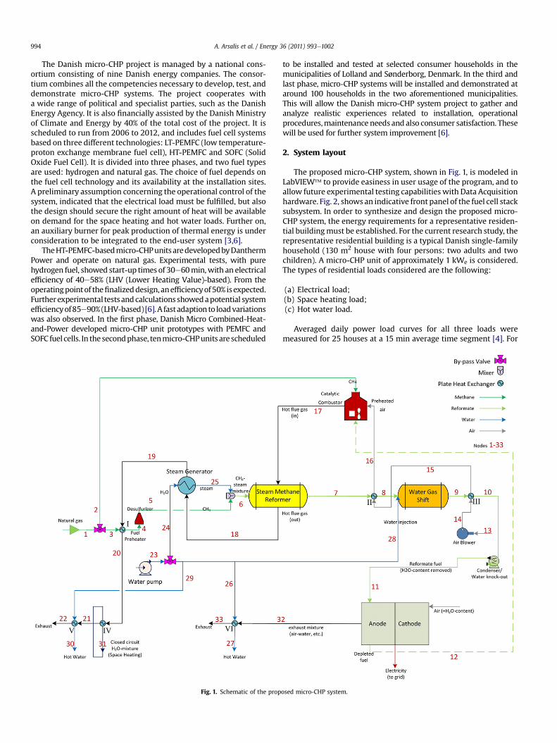
The kinetic model of the SMR reactor is described analytically in[9]. The assumed reactor material and its properties are describedin detail in [8]. The following assumptions were made for the SMRreactor:
� The reaction kinetics is based on a generalized Lang-muireHinshelwood kinetic model [8].
� The model considers a steady-state non-isothermal PFR, withthe presence of catalytic material in a PBR (packed-bed reactor)arrangement.
� The SMR reactor is heat integrated, as shown in Fig. 3, witha shell-and-tube heat exchanger design, where the externalshell-side wall is considered adiabatic.
� The reactor material is assumed inactive during the catalyticreaction.
For the current research study only the following reactions areconsidered:
CH4 þH2O#COþ 3H2 DH298 ¼ 206:2kJ=mol (14)
COþ H2O#CO2 þ H2 DH298 ¼ �41:1kJ=mol (15)
CH4 þ 2H2O#CO2 þ 4H2 DH298 ¼ 164:9kJ=mol (16)
The heat transfer model is based on [10], where the shell-and-tube heat integration model is based on a transient model. For thecurrent research study, the model was simplified in a steady-stateone, where the partial differential equations are reduced intoordinary differential equations. The convective heat transfer coef-ficient of the inside tube wall is based on a semi-empirical relationfor spherical packing [11].
The heat transfer coefficient for a packed-bed tubular reactor isobtained from the following empirical correlation,
hw ¼ 2:03Re0:8pkrefDi
exp�� 6dp
Di
�(17)
while the shell-side heat transfer coefficient is defined as,
hs ¼ 0:36�
ksDeq
��DeqGs
ms
�0:55�Cp;smsks
�1=3� msmwall
�0:14
(18)

Fig. 3. Schematic of the SMR reactor, modeled as a shell-and-tube heat exchanger.
A. Arsalis et al. / Energy 36 (2011) 993e1002 997
The flue gas temperature gradient is obtained by the energybalance in the shell-side,
dTsdz
¼ phsDoðTw � TsÞ_msCp;s
(19)
while the inside tube wall temperature is defined as,
Tw ¼ DohsTs þ DihwTrefDohs þ Dihw
(20)
3.3. WGS Reactor
The inlet composition for the WGS reactor is the sum of the exitcomposition of the SMR reactor and the injected water. The heatexchanger placed prior to the WGS reactor inlet, cools the WGSinlet temperature to an appropriate level, as needed by the WGSreactor. The CO (carbon monoxide) content, in terms of molarcomposition, should be reduced to an acceptable level of 0.1%e0.2%.The kinetic constant, based on a power law relationship, is at steadystate. The type of the converting catalyst and its deactivation aredescribed in detail in [12]. The kinetic model of the WGS reactor isdescribed in detail in [9,12]. The WGS reaction is,
COþ H2O#CO2 þ H2 (21)
The equilibrium constant given in [13],
KT ¼ exp�4400T
� 4:063�
(22)
The kinetic power law fit parameters are obtained from [12],
KWGS ¼ k0exp��Ea
RT
�(23)
The CO extent of reaction is given by,
dxCOdz
¼ urwiremesh3600rCO
_nCO;i(24)
while the temperature gradient is defined as,
dTdz
¼ rwiremesh
rgcp;massus�� rCOdHr;1
� (25)
3.4. Plate heat exchangers
In the current configuration several heat exchangers of the platetype are used, where all flows are unmixed. The main advantage of
a plate heat exchanger is its compactness. These heat exchangersfulfill the following system needs:
� Fuel pre-heater: Flue gas, exhausted from the steam genera-tor’s flue gas side, preheats the natural gas, before being mixedwith the superheated steam in the mixer.
� Water heater: The exhaust water mixture produced from thefuel cell stack is used to heat tap water at a temperature highenough for domestic use.
� Space heating heater: The exhaust water mixture producedfrom the fuel cell stack is used to heat the fluid (water mixture)in a closed circuit for space heating.
� High temperature reformate fuel cooler: it is located betweenthe SMR and theWGS reactors to cool the reformate gas exitingthe SMR reactor. The reformate gas must reach a lowertemperature before entering the WGS reactor. On the cold-sideof the heat exchanger, the air absorbs the heat before enteringthe combustor.
� Low temperature reformate fuel cooler: It is located after theWGS reactor and cools the reformate gas with ambient air. Thisis necessary to ensure the reformate fuel is at a low tempera-ture before entering the condenser, and subsequently the fuelcell stack. On the cold-side of the heat exchanger the ambientair is heated, and then send to the high temperature reformatefuel cooler for further heating, as explained above.
Themodeling of the heat exchangers is based on simple heat andenergy balances, where the heat transfer rate and the (overall heattransfer coefficient-area)-value needed to fulfill the heat exchangefor the given mass flow rates and inlet temperatures are calculated.
3.5. Mixers & by-pass valves
Themixers and by-pass valves used in themicro-CHP system arenecessary for the operation and the regulation of the system. Themodeling of eachmixer and by-pass valve is donewith simple massand energy balances, assuming no pressure losses.
3.6. Steam generator
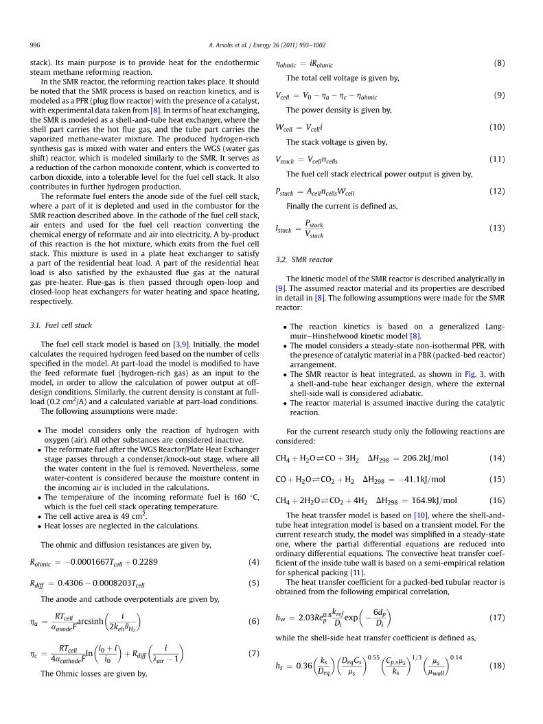
The steam generator model is divided into three sections:economizer, evaporator, and superheater (see Fig. 4). In the water/steam side of the SG (steam generator), water is pumped in theeconomizer section by the water pump, and undergoes phasechanges until it becomes superheated steam. The steam is then
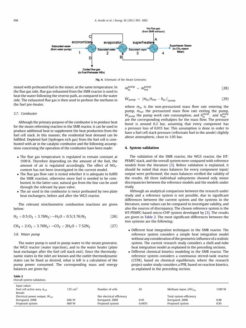
Fig. 4. Schematic of the Steam Generator.
A. Arsalis et al. / Energy 36 (2011) 993e1002998
mixedwith preheated fuel in themixer, at the same temperature. Inthe flue gas side, flue gas exhausted from the SMR reactor is used toheat thewater following the reverse path, as compared to thewaterside. The exhausted flue gas is then used to preheat the methane inthe fuel pre-heater.
3.7. Combustor
Although the primary purpose of the combustor is to produce heatfor the steam reforming reaction in the SMR reactor, it can be used toproduce additional heat to supplement the heat production from thefuel cell stack. In this manner, the residential heat demand can befulfilled. Depleted fuel (hydrogen-rich gas) from the fuel cell is com-busted with air in the catalytic combustor and the following assump-tions concerning the operation of the combustor have been made:
� The flue gas temperature is regulated to remain constant at1100 K. Therefore depending on the amount of the fuel, theamount of air is regulated accordingly. The effect of NOx-content has not been investigated in the current model.
� The flue gas flow rate is tested whether it is adequate to fulfillthe SMR reaction, otherwise more fuel is needed to be com-busted. In the latter case, natural gas from the line can be usedthrough the relevant by-pass valve.
� The air used in the combustor is twice preheated by two plateheat exchangers, before and after the WGS reactor.
The relevant stoichiometric combustion reactions are givenbelow:
H2 þ 0:5ðO2 þ 3:76N2Þ/H2Oþ 0:5ð3:76ÞN2 (26)
CH4 þ 2ðO2 þ 3:76N2Þ/CO2 þ 2H2Oþ 7:52N2 (27)
3.8. Water pump
The water pump is used to pump water to the steam generator,the WGS reactor (water injection), and to the water heater (plateheat exchanger after the fuel cell stack exit). Since the thermody-namic states in the inlet are known and the outlet thermodynamicstates can be fixed as desired, what is left is a calculation of thepump power consumed. The corresponding mass and energybalances are given by:
Table 2Overall system validation.
Input valuesFuel cell active area, Acell 135 cm2 Number of cellsResultsElectrical power output, _Wnet Net electrical efficienKorsgaard, 2008 666 W Korsgaard, 2008Proposed system 669 W Proposed system
_mpumpin ¼ _mpump
out (28)
_Wpump ¼ �_minðhout � hinÞ
pump (29)
where _min is the non-pressurized mass flow rate entering thepump, _mout the pressurized mass flow rate exiting the pump,_Wpump the pump work rate consumption, and hpump
in ; and hpumpout
are the corresponding enthalpies for the mass flow. The pressureboost is around 0.2 bar, assuming that every component hasa pressure loss of 0.015 bar. This assumption is done in order tohave a fuel cell stack pressure (reformate fuel in the anode) slightlyabove atmospheric, close to 1.05 bar.
4. System validation
The validation of the SMR reactor, the WGS reactor, the HT-PEMFC stack, and the overall systemwere compared with referencemodels from the literature [3]. Before validation is explained, itshould be noted that mass balances for every component input/output were performed; the mass balances verified the validity ofthe results. All three individual subsystems showed only minordiscrepancies between the reference models and the models understudy.
Although an analytical comparison between the research understudy and a reference system is not possible, due to significantdifferences between the current system and the systems in theliterature, some values can be compared to investigate validity, andalso the sources of discrepancy. The chosen reference system is theHT-PEMFC-based micro-CHP system developed by [3]. The resultsare given in Table 2. The most significant differences between thetwo systems are the following:
� Different heat integration techniques in the SMR reactor. Thereference system considers a simple heat integration modelwithoutanyconsiderationof thegeometric influenceofa realisticsystem. The current research study considers a shell-and-tubeheat integration model as explained in the preceding sections.
� Different chemical kinetics modeling in the SMR reactor. Thereference system considers a continuous stirred-tank reactor(CSTR), based on chemical equilibrium, where the researchproject under study considers a PFR, based on reaction kinetics,as explained in the preceding section.
65 Methane input, LHVCH41500 W
cy Total system efficiency0.45 Korsgaard, 2008 0.880.4455 Proposed system 0.95

Table 3Simulation results for full-load and part-load operation.
Node T(�C) _mðkg=sÞ xCH4xCO xCO2
xO2xN2
xair xH2O xH2
Full-load operation1 10.0 5.530E-05 1.000 0.000 0.000 0.000 0.000 0.000 0.000 0.0007 602.5 2.587E-04 0.031 0.048 0.088 0.000 0.000 0.000 0.336 0.4988 250.0 2.587E-04 0.031 0.048 0.088 0.000 0.000 0.000 0.336 0.4989 296.6 3.259E-04 0.026 0.003 0.112 0.000 0.000 0.000 0.402 0.45710 160.0 3.259E-04 0.026 0.003 0.112 0.000 0.000 0.000 0.402 0.45711 160.0 1.523E-04 0.043 0.005 0.187 0.000 0.000 0.000 0.000 0.76412 160.0 4.569E-05 0.043 0.005 0.187 0.000 0.000 0.000 0.000 0.76416 85.3 4.768E-03 0.000 0.000 0.000 0.000 0.000 1.000 0.000 0.00017 820.0 4.841E-03 0.000 0.000 0.006 0.195 0.777 0.000 0.022 0.00018 698.3 4.841E-03 0.000 0.000 0.006 0.195 0.777 0.000 0.022 0.00019 597.2 4.841E-03 0.000 0.000 0.006 0.195 0.777 0.000 0.022 0.00020 592.5 4.841E-03 0.000 0.000 0.006 0.195 0.777 0.000 0.022 0.00021 469.4 4.841E-03 0.000 0.000 0.006 0.195 0.777 0.000 0.022 0.00022 313.6 4.841E-03 0.000 0.000 0.006 0.195 0.777 0.000 0.022 0.00023 10.0 4.871E-03 0.000 0.000 0.000 0.000 0.000 0.000 1.000 0.00025 200.0 2.034E-04 0.000 0.000 0.000 0.000 0.000 0.000 1.000 0.00027 60.0 6.000E-04 0.000 0.000 0.000 0.000 0.000 0.000 1.000 0.00030 60.0 4.000E-03 0.000 0.000 0.000 0.000 0.000 0.000 1.000 0.00033 90.8 1.695E-03 0.007 0.001 0.031 0.000 0.000 0.809 0.152 0.00075%-load operation1 10.0 3.440E-05 1.000 0.000 0.000 0.000 0.000 0.000 0.000 0.0007 677.2 1.609E-04 0.007 0.076 0.077 0.000 0.000 0.000 0.306 0.5348 250.0 1.609E-04 0.007 0.076 0.077 0.000 0.000 0.000 0.306 0.5349 323.9 2.047E-04 0.006 0.006 0.122 0.000 0.000 0.000 0.356 0.50910 160.0 2.047E-04 0.006 0.006 0.122 0.000 0.000 0.000 0.356 0.50911 160.0 1.044E-04 0.009 0.010 0.190 0.000 0.000 0.000 0.000 0.79112 160.0 3.132E-05 0.009 0.010 0.190 0.000 0.000 0.000 0.000 0.79116 88.3 3.538E-03 0.000 0.000 0.000 0.000 0.000 1.000 0.000 0.00017 718.0 3.589E-03 0.000 0.000 0.005 0.197 0.778 0.000 0.020 0.00018 678.2 3.589E-03 0.000 0.000 0.005 0.197 0.778 0.000 0.020 0.00019 593.0 3.589E-03 0.000 0.000 0.005 0.197 0.778 0.000 0.020 0.00020 589.0 3.589E-03 0.000 0.000 0.005 0.197 0.778 0.000 0.020 0.00021 422.6 3.589E-03 0.000 0.000 0.005 0.197 0.778 0.000 0.020 0.00022 316.2 3.589E-03 0.000 0.000 0.005 0.197 0.778 0.000 0.020 0.00023 10.0 1.170E-03 0.000 0.000 0.000 0.000 0.000 0.000 1.000 0.00025 200.0 1.265E-04 0.000 0.000 0.000 0.000 0.000 0.000 1.000 0.00027 60.0 4.000E-04 0.000 0.000 0.000 0.000 0.000 0.000 1.000 0.00030 60.0 2.000E-03 0.000 0.000 0.000 0.000 0.000 0.000 1.000 0.00032 160.0 1.224E-03 0.001 0.002 0.030 0.000 0.000 0.813 0.153 0.00033 64.0 1.224E-03 0.001 0.002 0.030 0.000 0.000 0.813 0.153 0.00050%-load operation1 10.0 2.730E-05 1.000 0.000 0.000 0.000 0.000 0.000 0.000 0.0007 588.3 1.277E-04 0.041 0.041 0.088 0.000 0.000 0.000 0.355 0.4758 250.0 1.277E-04 0.041 0.041 0.088 0.000 0.000 0.000 0.355 0.4759 290.2 1.602E-04 0.035 0.003 0.106 0.000 0.000 0.000 0.423 0.43310 160.0 1.602E-04 0.035 0.003 0.106 0.000 0.000 0.000 0.423 0.43311 160.0 7.176E-05 0.060 0.004 0.184 0.000 0.000 0.000 0.000 0.75112 160.0 2.153E-05 0.060 0.004 0.184 0.000 0.000 0.000 0.000 0.75116 60.6 3.314E-03 0.000 0.000 0.000 0.000 0.000 1.000 0.000 0.00017 610.0 3.345E-03 0.000 0.000 0.004 0.199 0.781 0.000 0.015 0.00018 588.6 3.345E-03 0.000 0.000 0.004 0.199 0.781 0.000 0.015 0.00019 514.5 3.345E-03 0.000 0.000 0.004 0.199 0.781 0.000 0.015 0.00020 511.0 3.345E-03 0.000 0.000 0.004 0.199 0.781 0.000 0.015 0.00021 328.9 3.345E-03 0.000 0.000 0.004 0.199 0.781 0.000 0.015 0.00022 95.3 3.345E-03 0.000 0.000 0.004 0.199 0.781 0.000 0.015 0.00023 10.0 4.733E-03 0.000 0.000 0.000 0.000 0.000 0.000 1.000 0.00025 200.0 1.004E-04 0.000 0.000 0.000 0.000 0.000 0.000 1.000 0.00027 60.0 2.600E-04 0.000 0.000 0.000 0.000 0.000 0.000 1.000 0.00030 60.0 1.800E-03 0.000 0.000 0.000 0.000 0.000 0.000 1.000 0.00032 160.0 7.782E-04 0.010 0.001 0.031 0.000 0.000 0.807 0.152 0.00033 94.6 7.782E-04 0.010 0.001 0.031 0.000 0.000 0.807 0.152 0.00025%-load operation1 10.0 1.350E-05 1.000 0.000 0.000 0.000 0.000 0.000 0.000 0.0007 577.6 6.314E-05 0.048 0.036 0.088 0.000 0.000 0.000 0.367 0.4618 250.0 6.314E-05 0.048 0.036 0.088 0.000 0.000 0.000 0.367 0.4619 285.5 7.904E-05 0.041 0.002 0.103 0.000 0.000 0.000 0.436 0.41810 160.0 7.904E-05 0.041 0.002 0.103 0.000 0.000 0.000 0.436 0.41811 160.0 3.447E-05 0.072 0.004 0.183 0.000 0.000 0.000 0.000 0.74212 160.0 1.034E-05 0.072 0.004 0.183 0.000 0.000 0.000 0.000 0.74216 56.7 1.708E-03 0.000 0.000 0.000 0.000 0.000 1.000 0.000 0.00017 585.0 1.722E-03 0.000 0.000 0.004 0.200 0.782 0.000 0.014 0.00018 577.6 1.722E-03 0.000 0.000 0.004 0.200 0.782 0.000 0.014 0.000
(continued on next page)
A. Arsalis et al. / Energy 36 (2011) 993e1002 999

Table 3 (continued )
Node T(�C) _mðkg=sÞ xCH4xCO xCO2
xO2xN2
xair xH2O xH2
19 506.2 1.722E-03 0.000 0.000 0.004 0.200 0.782 0.000 0.014 0.00020 502.9 1.722E-03 0.000 0.000 0.004 0.200 0.782 0.000 0.014 0.00021 148.3 1.722E-03 0.000 0.000 0.004 0.200 0.782 0.000 0.014 0.00022 93.3 1.722E-03 0.000 0.000 0.004 0.200 0.782 0.000 0.014 0.00023 10.0 4.666E-03 0.000 0.000 0.000 0.000 0.000 0.000 1.000 0.00025 200.0 4.964E-05 0.000 0.000 0.000 0.000 0.000 0.000 1.000 0.00027 60.0 1.300E-04 0.000 0.000 0.000 0.000 0.000 0.000 1.000 0.00030 60.0 9.000E-04 0.000 0.000 0.000 0.000 0.000 0.000 1.000 0.00032 160.0 3.673E-04 0.012 0.001 0.031 0.000 0.000 0.805 0.152 0.00033 90.9 3.673E-04 0.012 0.001 0.031 0.000 0.000 0.805 0.152 0.000
Fig. 5. Current density and HT-PEMFC efficiency vs. Load.
Table 4Overall power-to-heat performance for the adopted load profile.
Load ð _WelectricalÞnet ð _QHExÞcogen: Total cogenerationHeat load fulfilled (%)
Winter, mean 540 840 47.2Winter, max 950 1560 51.8Summer, mean 380 580 193.0Summer, max 650 1000 64.1Spring, mean 460 700 76.9Spring, max 920 1470 54.6
A. Arsalis et al. / Energy 36 (2011) 993e10021000
� Some other differences in the layout of the system componentscan be noted as well; a steam generator and fuel pre-heater aremodeled in the current system under study, where a mixturevaporizer was modeled in the reference model. Also differentheating/cooling between streams is used (e.g. air coolers, etc.).
Nevertheless of the differences between the two systems, thevalidation has shown a good agreement of the two models, veri-fying the validity of the research project in study.
5. Results and discussion: On-design and off-design systemperformance
Off-design operational conditions and simulation at theseconditions provides valuable information on the operation of thecomponent/system, particularly on its range of applicability.Therefore, it is necessary to analyze the amount of electricity andheat produced by the micro-CHP system, in terms of size, part-load
Fig. 6. Electrical Load vs. Total Cogeneration Heat Load.
characteristics, etc. The results for all the nodes, shown in Fig. 1, aregiven with the following parameters: temperature, mass flow rate,and mole fractions. In Table 3, the results for full-load, 75%, 50% and25%-load operation are given. The fuel cell stack operates ata constant temperature of 160 �C to avoid fast degradation of themembrane, if operated at higher temperatures [14,15]. Also thetemperature is kept constant, because rapid and frequent variationsof the operating temperature would contribute to faster deterio-ration of the membrane [5,14]. The corresponding fuel cell oper-ating pressure is kept at a value slightly above atmospheric, since anincrease of pressure would not contribute significantly in thesystem efficiency, and also the degradation of the membranewouldbe faster [14,15].
The current density variation for the given loads and the HT-PEMFC stack efficiency (LHV) variation for the given loads are givenin Fig. 5. The current density is varied from 0.19 A/cm2 at full-loadlinearly up to 0.04 A/cm2 at 25% load. The efficiency follows ananalogous path, increasing at part-load to 45.5%.
The net electrical power output at full-load and part-loads vs.the corresponding cogeneration heat loads is shown in Fig. 6. Thesystem’s useful heat capacity was analyzed in Section 2. For thisload profile the net electrical power output, along with the corre-sponding total cogeneration heat output are given in Table 4. In the
Fig. 7. Mass flow variation of hydrogen, methane and carbon monoxide at full-loadoperation.
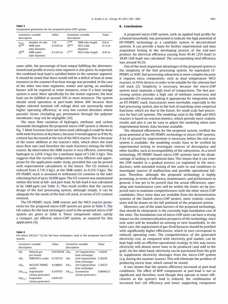
Table 5Component geometries for the proposed micro-CHP system.
Geometric variabledescription
Value Geometric variabledescription
Value
ncells Number of cells 176 LSMR SMR tube length 0.8 mDSMRi SMR inlet
tube diameter0.1016 m DWGS
i WGS tubediameter
0.13 m
DSMRo SMR outlet
tube diameter0.1322 m LWGS WGS tube length 0.45 m
A. Arsalis et al. / Energy 36 (2011) 993e1002 1001
same table, the percentage of heat output fulfilling the aforemen-tioned load profile at every time segment is also given. As expected,the combined heat load is satisfied better in the summer segment.It should be noted that there would still be a deficit of heat at someinstances in the summer if no heat storagewas provided. In the caseof the other two time segments, winter and spring, an auxiliaryburner will be required at some instances, even if a heat storagesystem is used. More specifically for the winter segment, the heatload can be fulfilled at around 50% in most instances. The systemshould avoid operation at part-loads below 20% because thenhigher selected nominal cell voltage does not necessarily meanhigher operating efficiency; at very low current densities whereparasitic losses (including gas permeation through the polymermembrane) may not be negligible [16].
The mass flow variation of hydrogen, methane, and carbonmonoxide throughout the proposed micro-CHP system is shown inFig. 7. Mole fractions have not been used (although it could be donewithmole fractions at dry basis), because itwould appear as if theH2content has decreased at the exit of theWGS reactor. This is becauseof the water addition at the reactor’s inlet, which alters the totalmass flow rate (and therefore the mole fractions) exiting the WGSreactor. By observation the SMR reactor is very efficient, convertinghydrogen to 2.01E-5 kg/s for a methane input of 5.52E-5 kg/s. Thissuggests that the current configuration is very efficient and appro-priate for the application under study, provided this can be provedwith experimental calculations in the future. The CO content isreduced from 2.71E-5 kg/s, at the SMR outlet, to 0.21E-5 kg/s. TheHT-PEMFC stack is assumed to withstand CO-contents in the inletreforming fuel of up to10,000 ppm. The CO-contentwasmaintainedwithin this limit at full- and part-load. At full-load it was calculatedto be 5480 ppm (see Table 3). This result verifies that the currentdesign of the fuel processing system, although simple, it can beadequate for the needs of the fuel cell stack, in terms of CO-contentremoval.
The HT-PEMFC stack, SMR reactor and the WGS reactor geom-etries for the proposed micro-CHP system are given in Table 5. TheUA-values for the heat exchangers used in the proposed micro-CHPsystem are given in Table 6. These component values satisfya compact, yet efficient micro-CHP system, as required for thisapplication [4].
Table 6UA-values [W/(m2-�C)] for the heat exchangers used in the proposed micro-CHPsystem.
Geometric variabledescription
Value Geometric variabledescription
Value
UAI Natural gaspre-heater
0.0538784 UAIV 1st Cogenerationheat exchanger
1.41641
UAII SMR/WGS cooler 0.720725 UAV 2nd Cogenerationheat exchanger
2.36245
UAIII WGS/HT-PEMFCcooler
0.548661 UAVI 3rd Cogenerationheat exchanger
1.39233
UASG,sup Superheater(steam generator)
0.107073 UASG,ec Economizer(steam generator)
0.0896212
UASG,ev Evaporator(steam generator)
0.843147
6. Conclusions
A proposed micro-CHP system, with an applied load profile fora Danish household, was presented to indicate the high potential ofHT-PEMFC technology as a candidate system in decentralizedsystems. It can provide a basis for further experimental and dataacquisition testing in the developing process of the end-userproduct. An electrical efficiency varying from 45.4% (25%-load) to38.8% (full-load) was calculated. The corresponding total efficiencywas around 95.2%.
One of themost important advantages of the proposed system isthe simplicity of the fuel processing system. An equivalent LT-PEMFC or SOFC fuel processing subsystem is more complex becauseit requires extra components, such as dual temperature WGSreactors, or PrOx devices in order to be suitable for the relevant fuelcell stack [2]. Simplicity is necessary, because the micro-CHPsystem must maintain a high level of compactness. The fuel pro-cessing system provides a high rate of methane conversion andacceptable CO-removal, making it appropriate for integration withan HT-PEMFC stack. Inaccuracies were inevitable, especially in thefuel processing system, due to the lack of matching semi-empiricalfunctions, which are due in the future, for small scale fuel proces-sors for fuel cell systems. The modeling used in the SMR and WGSreactors is based on reaction kinetics, which provide more realisticresults and also it can be easy to adjust the modeling when newexperimental kinetic data become available.
The obtained efficiencies for the proposed system, verified thegreat potential of the HT-PEMFC technology in micro-CHP systems.A lot of ground for improvement is necessary before the end-usersystem is available; the modeling results have to be verified byexperimental testing to investigate sources of discrepancy andother hurdles, such as incompatibility of the subsystems. As a noveltechnology, HT-PEMFC-based micro-CHP systems have the disad-vantage of lacking in operational data. This means that it can enterthe CHP market in a gradual process (as explained in the intro-duction), with extended testing of the units in real conditions toinvestigate sources of malfunction and possible operational fail-ures. Therefore, although the proposed technology is highlypromising, in terms of efficiency, maintenance, and performance ingeneral, it has yet to be proved that the actual efficiencies, oper-ating and maintenance costs will be within the limits set by pro-jected ones to maintain competitiveness with the other micro-CHPcandidates. Once more data are available from the demonstrationsystems of the Danish micro-CHP project, more realistic conclu-sions will be drawn on the full potential of the proposed system.
Moreover, one of the main barriers of the proposed technology,that should be eliminated, is the currently high installation cost ofthe units. The installation cost of micro-CHP units can have a strongimpact on the commercialization prospects of the technology, sincenew units will be installed on existing or new households. In thelatter case, the replacement of gas-fired furnaces should be justifiedwith significantly higher efficiencies, which in turn correspond toreduced operating costs. The competitiveness of the generatedelectricity cost, as compared with electricity grid market, can bekept high with an efficient operational strategy. In this way excesselectricity will almost never have to be produced (and sold to thegrid). On the other hand, electricity can be purchased from the gridto supplement electricity shortages from the micro-CHP system(e.g. during the summer season). This will eliminate the problem ofproducing excess heat, which cannot be stored.
It was shown that the system efficiency increased at part-loadconditions. The effect of BOP components at part-load is not sosignificant and therefore, even though they operate at lower effi-ciencies as the system’s load is reduced, the combination ofincreased fuel cell efficiency and lower supporting component

A. Arsalis et al. / Energy 36 (2011) 993e10021002
efficiencies can maintain high efficiencies as the load is reduced.This gives a significant leverage to the proposed micro-CHP systemas compared to conventional micro-CHP systems, such as Stirlingengines, micro-turbines, etc. The latter will typically experiencea significant drop-off in efficiency at part-load [17]. This gives theproposed system a fuel cost advantage, since this applicationrequires a significant amount of part-load operation.
The current results do not consider an exergy analysis which canbe used to provide amore complete picture in the overall design andsynthesis of the system, since it accounts both for the quantity andquality of all energyconversions present in a process. In thatmannera more cost-effective and better performing system could be ach-ieved, to reduce not just operational (fuel) costs, but also total (incl.capital) costs. Also an optimization process needs to be applied toverify the validity of the results. Specifically, the high thermal effi-ciency achieved by the high recovery of exhaust gases might beunrealistic, if components of reasonable size and efficiency (e.g. heatexchangers) cannot be coupled in the micro-CHP system. Whenthere is a very high temperature difference between the heatexchange streams, these have to be matched in order for the finaltemperature of one tobe close to the initial temperature of the other.Also the heat exchange ismore efficient if the flowheat capacities ofthe streams are similar. Otherwise streamswith high heat capacitiesmight need to be split in several stream flows. Therefore alternativedesigns of system/component configurations should be used withthe aid of heat integration methods, such as pinch analysis.
Finally, LabVIEW� was chosen as the modeling tool for thisresearch study for the reasons explained in the introduction.Although the end result can provide a high degree of easiness to theprogram user in terms of calculations, the modeling procedureproved to be very time-consuming. There is a great difficulty inadjusting and modifying highly complicated models, due to thegraphical modeling nature used in LabVIEW�. Also LabVIEW� hasa limited number of parameters that can be transferred froma subVI to the main VI (Virtual Instrument). Therefore, LabVIEW�modeling is more appropriate for single component dynamicsystems. Nonetheless, the current system can provide a good toolfor experimental testing in the future.
Acknowledgments
Theauthorswould like toacknowledge thesupportofDanfossandDantherm Power throughout the realization of this research study.
References
[1] Arsalis A, von Spakovsky MR, Calise F. Thermoeconomic modeling and para-metric study of hybrid solid oxide fuel cell-gas turbine-steam turbine powerplants ranging from 1.5 MWe to 10 MWe. Journal of Fuel Cell Science andTechnology 2009;6(1):011015.
[2] O’Hayre R, Colella W, Cha S, Prinz FB. Fuel cell fundamentals. Wiley; 2009.[3] Korsgaard AR, Nielsen MP, Kær SK. Part one: a novel model of HTPEM-based
micro-combined heat and power fuel cell system. International Journal ofHydrogen Energy 2008;33(7):1909e20.
[4] Korsgaard AR, Nielsen MP, Kær SK. Part two: control of a novel HTPEM-basedmicro combined heat and power fuel cell system. International Journal ofHydrogen Energy 2008;33(7):1921e31.
[5] Zhang J, Xie Z, Tang Y, Song C, Navessin T, Shi Z, et al. High temperature PEMfuel cells. Journal of Power Sources 2006;160(2):872e91.
[6] Pedersen AH, Balslev P. Demonstration of mCHP based on Danish fuel cells.Lucerne, Switzerland: European Fuel Cell Forum 2009; 2009.
[7] Kolb G. Fuel processing for fuel cells. Weinheim, Germany: Wiley-VCH; 2008.[8] Xu J, Froment GF. Methane steam reforming, methanation and water-gas
shift: 1. intrinsic kinetics. AIChE Journal 1989;35(1):88e96.[9] Nielsen MP. Modeling of proton exchange membrane fuel cell systems. Aal-
borg, Denmark: PhD Dissertation, Aalborg University; 2005.
[10] Kim K. Dynamic proton exchange membrane fuel cell system synthesis/designand operation/control optimization under uncertainty. Blacksburg, VA: PhDDissertation, Virginia Tech; 2008.
[11] Li C, Finlayson BA. Heat transfer in packed bedsea reevaluation. ChemicalEngineering Science 1977;32:1055e66.
[12] Keiski RL, Salmi T, Niemisto P, Ainassaari J, Pohjola VJ. Stationary and transientkinetics of the high temperature water-gas shift reaction. Applied Catalysis A:General 1996;137(2):349e70.
[13] Davies J, Lihou D. Optimal design of methane steam reformer. Chemical andProcess Engineering 1971;52:71e80.
[14] Korsgaard AR, Refshauge R, Nielsen MP, Bang M, Kær SK. Experimentalcharacterization and modeling of commercial polybenzimidazole-based MEAperformance. Journal of Power Sources 2006;162(1):239e45.
[15] Büchi FN, Inaba M, Schmidt TJ. Polymer electrolyte fuel cell durability. NewYork, NY, USA: Springer; 2009.
[16] Barbir F. PEM fuel cells: theory and practice. Elsevier; 2005.[17] Peacock A, Newborough M. Impact of micro-CHP systems on domestic
sector CO emissions. Applied Thermal Engineering 2005;25(17e18):2653e76.
Nomenclature
Acell: Fuel cell active area (cm2)Cp,s: Specific heat of shell-side gas in SMR (kJ/(kmol.K))dp: Catalyst diameter, SMR reactor (m)dHr,1: Enthalpy of reaction (kJ/mol)Di: Inlet diameter (m)Do: Outlet diameter (m)Deq: Equivalent diameter (m)F: Faraday constant (C/mol)Gs: Mass flux (kg/(m2.s))hs: Shell-side heat transfer coefficient (W/m2.K)hw: Tube-side heat transfer coefficient (W/m2.K)i: Current density (A/cm2)Istack: Fuel cell stack current (A)i0: Exchange current density (A/cm2)keh: H2 electro-oxidation rate constant (A/cm2)ki: Thermal conductivity of species i (W/K.m)KT: Equilibrium constantKWGS: Kinetic power law fit parameter (m^1.92/kmol^-0.36.kg.s)LHVi: Lower heating value of species i (J/kg)_mi: Mass flow rate of species i (kg/s)ncells: Number of cells in the fuel cell stack_nCO: CO molar feed rate (kmol/h)Pstack: Fuel cell stack electrical power output (W)_Qi: Heat transfer rate of component i (W)rCO: CO reaction rate (kmol/kg.s)R: Ideal gas constant (J/K.mol)Rdiff: Diffusion resistance (Ohm.cm2)Rohmic: Ohmic resistance (Ohm.cm2)Rep: Reynolds numberTcell: Fuel cell operating temperature (oC)Ti: Temperature of species i (oC)Vcell: Total cell voltage (V)Vstack: Fuel cell stack voltage (V)V0: Open circuit voltage (V)us: Superficial velocity (m/s)Wcell: Power density (W/m2)_Welectrical: Electrical power output (W)z: Distance along the reactor length (m)ai: Charge transfer coefficientha: Anode overpotential (V)hc: Cathode overpotential (V)hohmic: Ohmic losses (V)hi: Efficiency of component/system iqH2
: H2 adsorption/desorption constantlair: Air stoichiometry, cathode sidemi: Viscosity of species i (kg/s.m)rg: Density of the reformate gas (kg/m3)rwiremesh: Density of the wiremesh catalytic material (kg/m3)u: WGS reactor cross-sectional area (m)
Subscripts/superscriptscogen.: CogenerationHEx: Heat exchangerin: Input streamout: Output streamref: Reformate gass: Flue gasthermal: Thermal power
Copyright © 2022 FDOKUMEN