Feasibility of a new domestic CHP trigeneration with heat pump: I. Design and development
Upload
khangminh22Category
view
0download
0
Contents lists available at ScienceDirect
Biomass and Bioenergy
journal homepage: www.elsevier.com/locate/biombioe
Research paper
Development of a new micro CHP pellet stove technology
Ingwald Obernbergera, Gerhard Weißa,∗, Manuel Kösslb
a BIOS BIOENERGIESYSTEME GmbH, Hedwig-Katschinka-Straße 4, A-8020 Graz, Austriab RIKA Innovative Ofentechnik GmbH, Müllerviertel 20, A-4563 Micheldorf, Austria
A R T I C L E I N F O
Keywords:StoveCombined heat and power generation (CHP)WoodPelletThermoelectric generator
A B S T R A C T
BIOS and RIKA developed within the ERA-NET-project “Small-scale BM based CHP” a new micro CHP tech-nology based on a wood pellet stove (thermal capacity 10.5 kW) with a thermoelectric generator (TEG), thatenables the operation of the stove without electric grid connection. Thereby, the wear- and maintenance-free andalso noiseless TEG system is cooled by a water circuit which makes it possible to supply an additional room withheat. To achieve a self-sustaining operation of the pellet stove a TEG with an electric power of up to 50W wasinstalled into the casing of the pellet stove and the electricity consumption has been reduced significantly by anoptimization of the control system and the selection of appropriate low voltage components. Based on transientsystem calculations and CFD simulations as well as test runs with two testing plants the system has been opti-mized. To demonstrate the practical suitability of the new technology in real life, 8 h load cycle tests werecarried out. At these tests overall efficiencies up to 92.6% were achieved and in addition to the coverage of theown electricity consumption of the stove, 50W h surplus electricity were produced which can be used to chargemobile phones or other small consumers.
1. Introduction and objectives
Biomass based room heating systems are very common for spaceheating throughout Europe. In Austria, biomass stoves represent about50% of the total number of installed single room heaters [1]. In therecent 15 years pellet stoves became more and more popular due totheir advantages regarding automatic control, user friendliness (auto-mated ignition, easy and clean fuel handling) and their low emissions incomparison to logwood stoves. The current market for pellet stoves inEurope is in the range of 200,000 units per year whereby the marketswith the highest volumes are Italy and France [2–4]. However, the needof an external electric power supply to provide electricity for the start-up and operation is a disadvantage of pellet stoves especially with re-gard to fail-proof and independent heating systems. Thus, new andinnovative solutions to overcome this deficiency of pellet stoves arerequired to further support room heating technologies with high effi-ciencies and low emissions.
The implementation of TEG systems in logwood stoves has alreadybeen successfully realised [5,6]. In order to enable the operation of anautomatically controlled pellet stove without electric grid connection, anew micro CHP technology based on a wood pellet stove with a ther-moelectric generator (TEG) and appropriate power electronics wasdeveloped. A TEG consists of several thermoelectric modules (TEM)connected in series. In this paper TEM refers to the single TEM unit,
while TEG refers to the electricity generating system. The work wasdone in close cooperation of BIOS and RIKA within the ERA-NET-pro-ject “Small-scale BM based CHP”, funded by the Austrian Climate andEnergy Fund.
RIKA has worked in former projects on the development of a TEG tocover the own-electricity consumption of a pellet stove [7]. Thereby,the general applicability of the TEG technology for stoves was provenand a pre-selection of suitable TEMs took place. However, several key-issues remained unsolved:
• Number of TEMs needed to guarantee a sufficient power production
• Positioning of the TEMs to get high and homogenous hot sidetemperatures as constant temperature differences between the hotand the cold side at all TEMs implemented increase the achievableelectricity output of the system
• Selection of an appropriate cooling system for the TEG as the coldside temperature of the TEM has a considerable impact on theelectric efficiency
• Design of the pellet stove to guarantee a complete burnout of theflue gas before it is cooled by the TEG in order to minimise depositformation on the surface of the TEMs (deposits hamper the heattransfer and thus reduce the temperature difference between hotand cold side)
• Development of appropriate power electronics for the TEG system
https://doi.org/10.1016/j.biombioe.2018.06.020Received 29 September 2017; Received in revised form 15 June 2018; Accepted 24 June 2018
∗ Corresponding author.E-mail addresses: [email protected] (I. Obernberger), [email protected] (G. Weiß), [email protected] (M. Kössl).
Biomass and Bioenergy 116 (2018) 198–204
0961-9534/ © 2018 Elsevier Ltd. All rights reserved.
T

• Optimization of the power consumption of the pellet stove
• Minimum additional costs for the TEG integration in order to makethe grid independent system economically interesting
The goal of the project was to address the issues listed above and todevelop the new technology towards commercialisation. Within thispaper the new pellet stove technology with TEG is described and anoverview regarding the development and optimization of the newtechnology and the results achieved is given.
2. Methodology
In order to ensure an efficient and target oriented developmentduring the project, the following methodological approach was chosen.
2.1. Technical approach
The new CHP technology is based on an automatically controlledpellet stove with a thermal capacity of 10.5 kW which is coupled with aTEG and equipped with appropriate power electronics. The cooling ofthe TEG is done by a cooling device for the TEG which supplies thermalpower to room heaters. Additionally, an accumulator and appropriatepower electronics are considered for the new technology (see Fig. 1).
During operation of the pellet stove the TEG supplies the stove withelectricity. Surplus electricity is stored in an accumulator. The accu-mulator supplies electricity during the next start-up for the ignition andother power consumers (fan, fuel feeding, and control system) until theTEG starts the electricity production.
Thermoelectric generators enable a maintenance-free and silentelectric power generation from heat. Thus, this technology is particu-larly suitable to realise a grid-independent operation of stoves, whichare usually installed in residential areas (e.g. for heating of the livingroom). The principle of the TEG is based on the Seebeck effect, in whichheat is directly converted into electricity by two connected and differ-ently doped semiconductors placed at different temperatures (Fig. 2).
The electric output of the TEMs and thus the TEG is influenced bythe type of the TEM, the number of TEMs used, the temperature dif-ference between the cold and hot side of the TEMs/TEG (with risingtemperature difference the electric output is increasing) and the TEM/TEG cold side temperature (with rising cold side temperature the effi-ciency is decreasing). Thus, a high temperature difference between thecold and hot side combined with a low cold side temperature of theTEMs/TEG is the aim in order to achieve a high electric output of theTEG. In Fig. 3 a cross section of the new pellet stove micro CHP tech-nology shows the position of the TEG in the flue gas path. It is located
downstream the post combustion chamber where the flue gas tem-peratures are high and flue gas burn-out is already completed.
The electricity produced is stored in the accumulator for the nextstart-up of the pellet stove. The surplus electricity produced, when theaccumulator is fully charged, can be used to charge external devices viaUSB port implemented in the new power electronics.
2.2. Transient system calculations
For the definition of the number of TEMs needed to provide elec-tricity sufficient for the operation of the pellet stove and to evaluatedifferent cooling options for the TEG system, transient system calcula-tions were performed based on an in-house developed Microsoft Excel™spread sheet considering the heat-up, stable operation, load changesand cooldown phases of the system. These calculations enabled a rea-listic overall dynamic system modelling based on the given boundaryconditions regarding pellet stove operation, TEG and ambient. Thereby,different cooling options such as air cooling (II), heat storage (I) andcooling with a water circuit (III) were modelled and evaluated (seeFig. 4).
2.3. Selection of appropriate system components
As a first step towards a self-sustaining operation, the ownFig. 1. General approach of the new pellet stove micro CHP technology.
Fig. 2. General structure of a TEM (top) and photographs of the TEM with andwithout ceramic substrate (N … n-doped semiconductor; P … p-doped semi-conductor).
Fig. 3. Cross section of the new pellet stove CHP technology.
I. Obernberger et al. Biomass and Bioenergy 116 (2018) 198–204
199

consumption of the pellet stove had to be reduced. This was achievedby RIKA by selecting low voltage system components (ignitor, flue gasfan, fuel feeding system, water pump and accumulator). In a secondstep the power output had to be maximized. This goal could be ac-complished by adapting and optimizing the TEG, the accumulator andthe power electronics. As criteria for the selection of a suitable TEM, theacceptable maximum hot side temperatures (to increase the tempera-ture difference between hot and cold side of the TEM), high electricefficiencies as wall as low costs were considered. The selected type ofTEM has subsequently been implemented into the testing plant 1 and 2.For all components selected the investment costs were, apart fromsuitable technical specifications, an important basis of decision, sincethe additional costs for the new CHP technology compared to standardpellet stoves should be kept to a minimum.
2.4. Construction of testing plants (2-stage approach)
Based on the results of the development work described above, apre-optimized prototype of the pellet stove technology equipped with aTEG and a cooling system (water circuit) was constructed (testing plant1). The test runs with testing plant 1 focused on the performance of thepellet stove regarding efficiency and emissions, the general functionand the achievable hot and cold side temperatures of the TEG for dif-ferent operation loads of the pellet stove as well as the performance ofthe cooling water circuit.
Based on the data and experiences gained from the test runs withtesting plant 1, the system was optimized and a second – close-to-the-product - testing plant was constructed and tested. For testing plant 2,especially the TEM position in the stove as well as the heat exchangerson the hot and cold side of the TEMs were modified in order to increasethe electric output of the system. Furthermore, the air staging and in-sulation of the main and the post combustion chamber were modified inorder to improve the burnout quality.
In addition, for testing plant 2 a suitable power electronics werealready available and an accumulator was integrated. Consequently,with testing plant 2 a grid-independent start-up and operation waspossible and thus the overall system could be evaluated at differentoperation modes under close-to-real-life conditions.
2.5. CFD based design of the pellet stove with integrated TEMs
Based on the preliminary design of the pellet stove with integratedTEG a stepwise optimization took place by CFD (Computational FluidDynamics) simulations as a basis for testing plant 1. Based on the resultsof the test runs performed, and the adapted design of the pellet stoveprovided by RIKA, CFD simulations for the testing plant 2 were per-formed and the system was improved gradually. Table 1 gives anoverview over the CFD models considered. The main purposes of theCFD simulations performed for the new pellet stove CHP technologywere to achieve:
• Optimal positioning of TEMs regarding high and homogeneous hotside temperatures
• Efficient CO burnout and air staging
• Good flushing of the window by secondary air to ensure a cleanwindow
• High total efficiency
• Low temperatures for the water pump and accumulator in the pelletstove casing
2.6. Measurement and analysis methods applied
A significant number of different measurement technologies wereapplied in order to gain detailed information about the performance ofthe new micro CHP technology. The following continuous measure-ments were performed during the test runs with testing plant 1 and 2:
• Operation parameters: flue gas temperature according to EN 13240,combustion chamber temperature and chimney draught, volumeflow of flue gas, combustion air and cooling water circuit as well astemperatures of the hot and cold side of the TEG and in the coolingwater circuit
• Flue gas composition downstream the stove using standard flue gasanalysers for O2 (paramagnetic sensor), CO, NO (NDIR) and OGC(FID)
• Determination of the particle size distribution and concentration ofaerosols in the flue gas downstream the stove with an electrical low-pressure impactor (ELPI)
• Electricity consumption (separate measurement of the ignitor, fluegas fan, water pump for the water circuit and electronics), electricityproduction of the TEG (voltage and current) and voltage of the ac-cumulator
Besides these continuous measurements, fuel and ash samples weretaken periodically and the total fly ash (TSP) and aerosol concentrationsin the flue gas downstream the stove were determined with a filtermethod and a 9-stage Berner-type low-pressure impactors (BLPI) re-spectively.
Fig. 4. Structure of the transient system calculations for the three (I - III) cooling options investigated.
Table 1Overview over CFD models applied.
Model
Combustion ofpellets:
Empirical combustion- and release model (in-housecode) for fixed beds [8]
Turbulence: Realizable k-ε modelGas phase
combustion:Eddy dissipation mode global methane 3-step mechanism(CH4, CO, CO2, H2, H2O and O2) [9]
Radiation: discrete ordinates model/weighted-sum-of-gray-gasesmodel for gas radiation (gray radiators CO2, H2O)/sootformation and radiation model of soot particles
Shell-conductionmodel:
3D - heat conduction in the metal sheets surrounding thecombustion zone
I. Obernberger et al. Biomass and Bioenergy 116 (2018) 198–204
200

For selected test runs representative samples of the fuel used (woodpellets ENPlusA1) were analysed regarding the moisture content (de-termination of weight loss at 105 °C - ÖNORM EN 14774–1.2009 1201), ash content (method according to ÖNORM EN 14775:2009 12 15)and main elements C, H and N (ÖNORM EN 15104:2001 04 01).
2.7. Performance of test runs, evaluation and stepwise optimization of thetechnology
Test runs at different loads (30%, 50%, 65% and 100% of nominalload) were performed with both testing plants to evaluate the newsystem in regard to the thermal power of the pellet stove, the thermalefficiency as well as the gaseous and particulate emissions.Furthermore, the test runs focused on the electricity production of theTEG, the electricity consumption of the pellet stove and the perfor-mance of the water cooling system.
Additional test runs were performed with testing plant 2 in order tooptimize the start-up and shutdown procedure concerning electricityconsumption and production. Moreover, “worst case” tests regardingbreakdown of the water pump were performed. Finally, load cycle testswere carried out to demonstrate the practical suitability of the newtechnology in real life. The applied load cycle test has been developedwithin [10] based on field monitoring data of pellet stoves with andwithout water jacket. The duration of the load cycle test is 8 h andincludes four different load phases and three start-ups of the pellet stove(see Fig. 5).
The test runs were evaluated in detail and mass and energy balancesas well as carbon balances were made for plausibility checks.
3. Results and discussion
The transient system calculations pointed out, that due to the lowand stable TEG cold side temperatures achievable, the water circuit wasidentified as the most suitable cooling option for the TEG. Furthermore,this cooling option offers the possibility to heat an additional livingroom. In addition, the calculations pointed out that about 10–12 TEMsare required to ensure a sufficient power production of the TEG at anyload (i.e. from minimum partial load at 30% to nominal load of thepellet stove).
The test runs with testing plant 1 showed very promising resultsregarding thermal efficiency and gaseous emissions. The electric powerpotential of the TEG depends on the temperature difference betweencold and hot side of the TEMs/TEG and is thus directly correlated to thepower of the pellet stove. Results showed that at a temperature dif-ference of 60 °C (achieved at 30% part load of the pellet stove) theelectric power potential is 10W, while for a temperature difference of200 °C, which can be reached at nominal load of the pellet stove, the
electric power potential increases up to 50W (Fig. 6). The averageelectricity consumption of the pellet stove (including the power con-sumption of the pump for the water circuit but excluding the powerelectronics which were not installed in testing plant 1) amounted to10.1W at nominal load. The cooling system worked properly and thefeed temperatures were in the range from 35 to 60 °C (depending on thestove load).
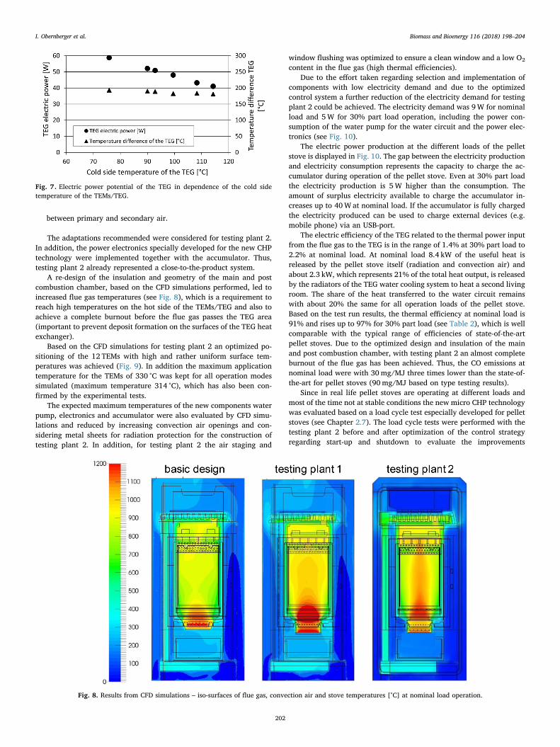
In addition, the impact of the TEM/TEG cold side temperature(influenced by the cooling system applied) on the electric output wasinvestigated. Therefore, test runs with varying cold side temperatures(by adjusting the operation parameters of the cooling system) and al-most constant hot side temperatures (stable load of the pellet stove)have been performed. The test run results confirmed the expectationsand underlined the huge influence of the cold side temperature on theelectricity output of the TEG system of about 0.5W/K (see Fig. 7). Thus,an efficient cooling of the TEMs is essential to reach a high electricoutput.
The test runs with testing plant 1 showed that the general concept ofthe new CHP technology is working properly. However, the results ofthe test runs and the results of subsequent CFD simulations also re-vealed the potential for further optimization. The main areas for opti-mizations were:
• Repositioning of the TEMs in order to achieve higher and homo-geneous temperatures on the hot side of the TEMs
• Improved TEG cooler design
• Improved burn-out quality and minimization of depositions on thefront window of the main combustion chamber by improving theinsulation of the main combustion chamber and modifying the ratio
Fig. 5. Load cycle test for pellet stoves [9].
Fig. 6. Electric power potential of the TEG for testing plant 1 in dependence ofthe stove operation load and temperature difference between cold and hot sideof the TEMs/TEG respectively.
I. Obernberger et al. Biomass and Bioenergy 116 (2018) 198–204
201
between primary and secondary air.
The adaptations recommended were considered for testing plant 2.In addition, the power electronics specially developed for the new CHPtechnology were implemented together with the accumulator. Thus,testing plant 2 already represented a close-to-the-product system.
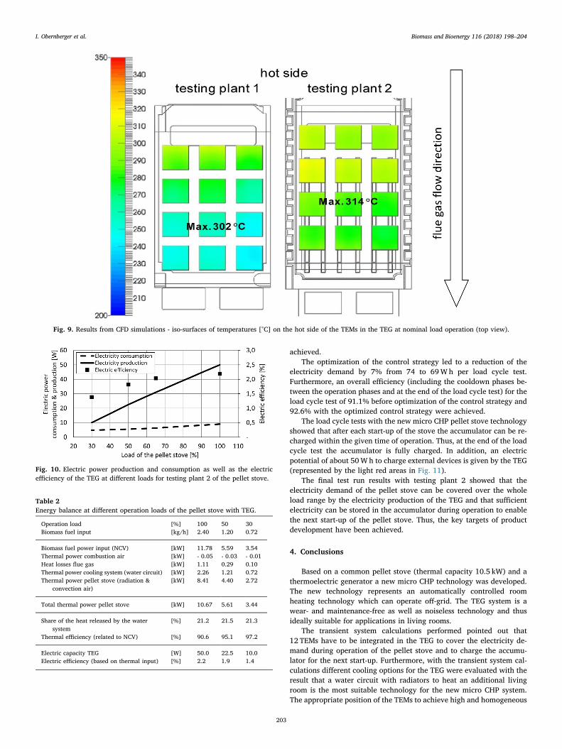
A re-design of the insulation and geometry of the main and postcombustion chamber, based on the CFD simulations performed, led toincreased flue gas temperatures (see Fig. 8), which is a requirement toreach high temperatures on the hot side of the TEMs/TEG and also toachieve a complete burnout before the flue gas passes the TEG area(important to prevent deposit formation on the surfaces of the TEG heatexchanger).
Based on the CFD simulations for testing plant 2 an optimized po-sitioning of the 12 TEMs with high and rather uniform surface tem-peratures was achieved (Fig. 9). In addition the maximum applicationtemperature for the TEMs of 330 °C was kept for all operation modessimulated (maximum temperature 314 °C), which has also been con-firmed by the experimental tests.
The expected maximum temperatures of the new components waterpump, electronics and accumulator were also evaluated by CFD simu-lations and reduced by increasing convection air openings and con-sidering metal sheets for radiation protection for the construction oftesting plant 2. In addition, for testing plant 2 the air staging and
window flushing was optimized to ensure a clean window and a low O2
content in the flue gas (high thermal efficiencies).Due to the effort taken regarding selection and implementation of
components with low electricity demand and due to the optimizedcontrol system a further reduction of the electricity demand for testingplant 2 could be achieved. The electricity demand was 9W for nominalload and 5W for 30% part load operation, including the power con-sumption of the water pump for the water circuit and the power elec-tronics (see Fig. 10).
The electric power production at the different loads of the pelletstove is displayed in Fig. 10. The gap between the electricity productionand electricity consumption represents the capacity to charge the ac-cumulator during operation of the pellet stove. Even at 30% part loadthe electricity production is 5W higher than the consumption. Theamount of surplus electricity available to charge the accumulator in-creases up to 40W at nominal load. If the accumulator is fully chargedthe electricity produced can be used to charge external devices (e.g.mobile phone) via an USB-port.
The electric efficiency of the TEG related to the thermal power inputfrom the flue gas to the TEG is in the range of 1.4% at 30% part load to2.2% at nominal load. At nominal load 8.4 kW of the useful heat isreleased by the pellet stove itself (radiation and convection air) andabout 2.3 kW, which represents 21% of the total heat output, is releasedby the radiators of the TEG water cooling system to heat a second livingroom. The share of the heat transferred to the water circuit remainswith about 20% the same for all operation loads of the pellet stove.Based on the test run results, the thermal efficiency at nominal load is91% and rises up to 97% for 30% part load (see Table 2), which is wellcomparable with the typical range of efficiencies of state-of-the-artpellet stoves. Due to the optimized design and insulation of the mainand post combustion chamber, with testing plant 2 an almost completeburnout of the flue gas has been achieved. Thus, the CO emissions atnominal load were with 30mg/MJ three times lower than the state-of-the-art for pellet stoves (90mg/MJ based on type testing results).
Since in real life pellet stoves are operating at different loads andmost of the time not at stable conditions the new micro CHP technologywas evaluated based on a load cycle test especially developed for pelletstoves (see Chapter 2.7). The load cycle tests were performed with thetesting plant 2 before and after optimization of the control strategyregarding start-up and shutdown to evaluate the improvements
Fig. 7. Electric power potential of the TEG in dependence of the cold sidetemperature of the TEMs/TEG.
Fig. 8. Results from CFD simulations – iso-surfaces of flue gas, convection air and stove temperatures [°C] at nominal load operation.
I. Obernberger et al. Biomass and Bioenergy 116 (2018) 198–204
202
achieved.The optimization of the control strategy led to a reduction of the
electricity demand by 7% from 74 to 69Wh per load cycle test.Furthermore, an overall efficiency (including the cooldown phases be-tween the operation phases and at the end of the load cycle test) for theload cycle test of 91.1% before optimization of the control strategy and92.6% with the optimized control strategy were achieved.
The load cycle tests with the new micro CHP pellet stove technologyshowed that after each start-up of the stove the accumulator can be re-charged within the given time of operation. Thus, at the end of the loadcycle test the accumulator is fully charged. In addition, an electricpotential of about 50W h to charge external devices is given by the TEG(represented by the light red areas in Fig. 11).
The final test run results with testing plant 2 showed that theelectricity demand of the pellet stove can be covered over the wholeload range by the electricity production of the TEG and that sufficientelectricity can be stored in the accumulator during operation to enablethe next start-up of the pellet stove. Thus, the key targets of productdevelopment have been achieved.
4. Conclusions
Based on a common pellet stove (thermal capacity 10.5 kW) and athermoelectric generator a new micro CHP technology was developed.The new technology represents an automatically controlled roomheating technology which can operate off-grid. The TEG system is awear- and maintenance-free as well as noiseless technology and thusideally suitable for applications in living rooms.
The transient system calculations performed pointed out that12 TEMs have to be integrated in the TEG to cover the electricity de-mand during operation of the pellet stove and to charge the accumu-lator for the next start-up. Furthermore, with the transient system cal-culations different cooling options for the TEG were evaluated with theresult that a water circuit with radiators to heat an additional livingroom is the most suitable technology for the new micro CHP system.The appropriate position of the TEMs to achieve high and homogeneous
Fig. 9. Results from CFD simulations - iso-surfaces of temperatures [°C] on the hot side of the TEMs in the TEG at nominal load operation (top view).
Fig. 10. Electric power production and consumption as well as the electricefficiency of the TEG at different loads for testing plant 2 of the pellet stove.
Table 2Energy balance at different operation loads of the pellet stove with TEG.
Operation load [%] 100 50 30Biomass fuel input [kg/h] 2.40 1.20 0.72
Biomass fuel power input (NCV) [kW] 11.78 5.59 3.54Thermal power combustion air [kW] - 0.05 - 0.03 - 0.01Heat losses flue gas [kW] 1.11 0.29 0.10Thermal power cooling system (water circuit) [kW] 2.26 1.21 0.72Thermal power pellet stove (radiation &
convection air)[kW] 8.41 4.40 2.72
Total thermal power pellet stove [kW] 10.67 5.61 3.44
Share of the heat released by the watersystem
[%] 21.2 21.5 21.3
Thermal efficiency (related to NCV) [%] 90.6 95.1 97.2
Electric capacity TEG [W] 50.0 22.5 10.0Electric efficiency (based on thermal input) [%] 2.2 1.9 1.4
I. Obernberger et al. Biomass and Bioenergy 116 (2018) 198–204
203

hot side temperatures were identified by CFD simulations. Furthermore,CFD simulations were also used to optimize the flue gas burnout and toevaluate and reduce the maximum surface temperatures of the addi-tional components needed for the new technology (water pump, accu-mulator).
By selecting appropriate low voltage components and optimizationof the control strategy finally a reduction of the electricity consumptionof the pellet stove down to 9W (including the power consumption ofthe pump for the water circuit) has been achieved.
Based on the simulations performed, testing plant 1 equipped with aTEG and its respective cooling system was constructed and manu-factured. The test runs with testing plant 1 focused on the performanceof the pellet stove regarding efficiency and emissions, the achievablehot and cold side temperatures of the TEMs/TEG for different operationloads as well as the performance of the cooling water circuit. Theevaluation of the test runs show satisfying results regarding the coolingsystem and the thermal efficiency of the pellet stove as well as pro-mising electric power potential of the TEMs. However, to increase theelectricity production of the TEG and to further reduce the emissions ofthe pellet stove an optimization of the testing plant by applying addi-tional CFD simulations took place and a second – close-to-the-product –testing plant was constructed and tested.
The focus of the test runs with testing plant 2 were on the evaluationof the overall system at the different operation modes and on load cycletests to demonstrate the practical suitability of the new technology inreal life.
The evaluation of the test runs has shown a surplus electricityproduction of about 40W at nominal load and that even at 30% partload the electricity demand of the pellet stove can be covered by theelectricity generated by the TEG. The load cycle tests with testing plant2 demonstrated, that a grid-independent start-up and operation at dif-ferent loads is possible. Thereby, an overall efficiencies up to 92.6%were achieved and in addition to the coverage of the own electricityconsumption of the stove, 50W h surplus electricity were producedwhich can be used to charge mobile phones or other small consumers.Moreover, due to the water cooling system with feed temperatures inthe range from 35 to 60 °C (depending on the stove load) and a thermalcapacity of up to 2.2 kW, a second living room can be heated by the newtechnology. The final design of the new micro-CHP system and long-
term testing of the new components is currently ongoing.
Acknowledgements
The work was carried out within the scope of the ERA-NETBioenergy programme “7th Joint Call for Research and DevelopmentProposals of ERA-NET Bioenergy”.
We gratefully acknowledge the Austrian climate and energy fund,for funding the project “Small-scale BM based CHP” (grant number843799) under its program “e!MISSION.at – 4th call”.
References
[1] Statistik Austria: Energiestatistik: MZ Energieeinsatz der Haushalte 2015/2016,Statistik Austria Bundesanstalt Statistik Österreich, Vienna, Austra, (2016).
[2] P. Biermayr, et al., Innovative Energie-technologien in ÖsterreichMarktentwicklung 2015 Bundesministerium für Verkehr, Innovation undTechnologie, Wien, Austria, 2016.
[3] European Commission DG TREN, Preparatory Studies for Eco-design Requirementsof EUPs (II): Lot 15 Solid Fuel Small Combustion Installations, Task 2: Economicand Market Analysis –Final Version December 2009, (2009).
[4] H. Haneder, Biomasse-heizungserhebung 2017, LandwirtschaftskammerNiederösterreich, Abteilung Betriebswirtschaft und Technik, St, Pölten, Austria,2017.
[5] A.M. Guodarzi P, et al., Integration of thermoelectric generators and wood stove toproduce heat, hot water, and electrical power; Department of MechanicalEngineering, Babol Noshiravani University of Technology, Babol, Iran, Journal ofElectric Materials 42 (7) (2013).
[6] A. Montecucco, J. Sivitera, A.R. Knox, A combined heat and power system for solid-fuel stoves using thermoelectric generators, The 7th International Conference onApplied Energy – ICAE, School of Engineering, University of Glasgow, Glasgow, UK,2015.
[7] M. Moser, S. Aigenbauer, S. Feldmeier, H. Stressler, E. Höftberger, Bewertung vonthermos-elektrischen Modulen mittels eines mit Pellets befeuerten Teststands;BIOENERGY 2020+ GmbH, Wieselburg, Austria, (2015).
[8] R. Scharler, C. Benesch, A. Neudeck, I. Obernberger, CFD based design and opti-misation of wood log fired stoves, Proc. of the 17th European Biomass Conference,June 2009, Hamburg, Germany, 2009 ISBN 978-88-89407-57-3, pp. 1361–1367,ETA-Renewable Energies (Ed.), Florence, Italy.
[9] R. Scharler, Entwicklung und Optimierung von Biomasse-Rostfeuerungen durchCFD-Analyse, PhD Thesis Institute for Process Engineering, Graz University ofTechnology, Austria, 2001.
[10] G. Reichert, et al., Definition of suitable measurement methods and advanced typetesting procedure for real life conditions; final report of the “beReal” project,funded by the FP7-SME-2013-2, Research for SME Associations within the 7th
Framework Programme of the EU, 2016 http://www.bereal-project.eu.
Fig. 11. Load cycle tests performed with testing plant 2 and optimized control system (Explanations: light red areas show the potential to charge external devices).(For interpretation of the references to colour in this figure legend, the reader is referred to the Web version of this article.)
I. Obernberger et al. Biomass and Bioenergy 116 (2018) 198–204
204
Copyright © 2022 FDOKUMEN