
IAEA TECHNICAL COMMITTEE MEETING ON PELLET ...
190
1X1 S-m! --1 IAEA TECHNICAL COMMITTEE MEETING ON PELLET INJECTION ?• Japan Atomic Fncrgy Research Institute N&Ua, Ibsiaki-ken, Japan Mcy 10 -12, 1993
-
Upload
khangminh22 -
Category
Documents
-
view
0 -
download
0
Transcript of IAEA TECHNICAL COMMITTEE MEETING ON PELLET ...

1X1 S-m! - - 1
IAEA TECHNICAL COMMITTEE MEETINGON
PELLET INJECTION ?•
Japan Atomic Fncrgy Research InstituteN&Ua, Ibsiaki-ken, Japan
Mcy 10 -12, 1993

? M
i. IAEA TECHNICAL COMMITTEE MEETING
f ONPELLET INJECTION
Japan Atomic Energy Research InstituteNaka, Ibaraki-ken, Japan
May 10 -12, 1993

< M
Foreword
, The IAEA Technical Committee Meeting on Pellet Injection wasj% held from 10 to 12 May 1993 at Japan Atomic Energy Research
• j . Institute, Naka, Ibaraki-ken, Japan.| The purpose of the meeting is to review the latest results on'- pellet injection and its effects on confinement. The topics
covered by the meeting include: 1) ablation of pellets, particlefueling results, 2) effects on confinement; improved mode, edgeeffects, MHD activity, impurity transport, 3) injector technology,diagnostics by pellets.About 30 experts including 11 scientists from abroad attendedthe meeting, presented 23 papers.
The editors appreciate all of the authors for delivering theirpapers. Thanks are also due to the attendance and the staffsof the meeting for their help in making the meeting successful.Finally, we would like to thank the International Atomic Energy
A Agency for the support of this meeting.
Masayuki NAGAMIYutaka KAMADA

• « •
";0
i
I.
• ' • ' • i f -
IAEA TCM on Pellet Injection
Agenda and Presentations
Monday. Mav 10. 1993
9:15 IAEA Welcome Address D. Banner
9:20 Welcome Address S. Tamura9:25 Opening Address M. Nagami
1 9:30 TFTR Deuterium Pellet Injection ExperimentsG.L.Schmidt
2 10:05 High-Performance JET Plasmas with
Pellet Injection P. Kupschus
10:40 coffee
3 10:50 Pellet Injection study in JT-60U R.Yoshino
4 11:25 Pellet Programme on TORE SUPRA M. Chatelier
12:00 lunch
5 13:10 Pellet Injector Research Activities atOak Ridge National Laboratory S. K. Combs
6 14:10 High-Speed Repetitive Pellet Injector Prototype forMagnetic Confinement Fusion Research
A.Frattolillo7 14:45 Injection of Solid D2 Pellets into
The Frascati Tokamak Upgrade
15:20 coffee
S. Migliori
8 15:35 Plasma Performance of TEXTORafter Pellet Injection
9 16:10 Pellet Injection Related Research at RTP
10 16:45 Pellet Injection Studies in the R&DDivision of the LHD Project
11 17:20 Developments of High Speed PelletInjector at NIFS
K. H. FinkenA.A.M. Oomens
K. N. Sato
S.Sudo
19:00 Welcome Reception

* - • • •
i. it,.,,*
Tuesday. Mav 11. 1993
12 9:15 Snake-Like Density Oscillations by PelletInjection and its Relation with SawtoothActivities in the TEXTOR Plasmas K. N. Sato
13 9:50 Strong Magnetic Fluctuations due to anAblating Pellet, and Fueled ParticleResponse to the SOL and Divertor H. Zushi
10:25 coffee
14 10:35 MHD activities in pellet injected dischargesin JT-60 and JT-60U Y. Kamada
15 11:10 Fuelling of JET H-mode and Limiter Plasmasby Deuterium Pellet Injection
16 11:45 Pellet Injector Technology at JET
12:20 lunch
17 13:30 Pellet Injector in JT-60U
18 14:05 Recent Results on Pellet Physicsand Technology for ITER in TechnicalUniversity
G. L. Schmidt
P.Kupschus
H.Hiratsuka
B. V. Kuteev
19 14:40 The Single and Multishot " In-Situ" Pellet Injectorsat St. Petersburg Technical University I. Viniar
( B. V. Kuteev )15:15 coffee
20 15:30 Development of Injection Angle ControllableSystem of Ice Pellets and its Application tothe JIPP T-IIU Tokamak H. Sakakita
21 16:05 Development of Advanced Railgun for Injection of
Hypervelocity Hydrogen Pellets into Tokamak
K. Kim
22 16:40 Development of Railgun Pellet Injector Using
a Laser-Induced Plasma Armature M. Onozuka
23 17:15 Railgun Using Permanent Magnet for Ice
Pellet Injection H. Akiyama
v
19:00 Workshop Dinner

r"ft ; .mXr^*' ' Wednesday. Mav 12. 1993
1 9:15 JT-60U Tour
^ Summary and Discussion of Future Application to Next Devicesl*|, 10:15 Plasma Experiments R. YoshinoA 11:20 coffee '•I 11:30 Injector Technology S. K. Combs -i
12:35 Closing of the Meeting
12:40 lunch
1
i .,•
f
, J
List of Participants
Akiyama, HidenoriKumamoto University, Dept. of Electrical EngineeringKurokami 2 -39 -1 , Kumamoto 860, ,•*J A P A NT E L 81-96-344-2111 Ext. 3618FAX. 81-96-345-1553
Banner , David L. "••IAEAP. 0 . Box 100, A-1400, Vienna, • IAUSTRIATEL. 43-431-2360-1756FAX. 43-431-234564
Chatelier, MichelCEA sur la Fusion Controlee, Centre d'Etudes de Cadarache13108 Saint Paul les Durance cedex,FranceTEL. 33-42-256342FAX. 33-42-256233
Combs, Stephen K. .Oak Ridge National LaboratoryP. O. Box 2009, Oak Ridge, TN 37831-8071U. S. A.TEL. 1-615-574-9985FAX. 1-615-576-7926
j Finken, Karl HeinzJ KFA-JULICH, JNST. F. PLASMA PHYSIK(4- 517 Julich,•3; FRG.Hi TEL 49-2461-61-5646& FAX. 49-2461-61-5452y] Frattolillo, Antonio; I ENEA, VIA ENRICO FERMI, 27, i 00044 FRASCATI, ROMA,
( ITALY': TEL. 39-06-94001ft^ FAX. 39-06-94005400
Hiratsuka, HajimeNaka Fusion Research Establishment, Japan Atomic Energy Research InstituteNaka-machi, Naka-gun, Ibaraki-ken, 311-01JAPANTEL. 81-292-70-7438FAX. 81-292-70-7419

pi^» | / Kamada, YutakaNaka Fusion Research Establishment, Japan Atomic Energy Research InstituteNaka-machi, Naka-gun, Ibaraki-ken, 311-01JAPAN
j TEL 81-292-70-7320* -. FAX. 81-292-70-7419
if, Kanno, MasahiroKobe Steel Ltd.
£ '• 5-5, Takatsukadai 1-chome, Nisi-ku, Kobe, 651-22; ' JAPAN% TEL 81-78-992-5528
FAX. 81-78-992-5529
Kasai, SatoshiJapan Atomic Energy Research Institute2-4 Shirakata, Shirane, Tokaimura, Naka-gun, Ibaraki-ken, 319-11JAPANTEL. 81-292-82-5951FAX. 81-292-82-5614
Katsuki, SunaoKumamoto University, Dept. of Electrical EngineeringKurokami 2-39-1, Kumamoto 860,JAPANTEL 81-96-344-2111 Ext. 3618FAX. 81-96-345-1553
Kim, Kyekyoon:J University of Illinoisi 155 Everitt Laboratory
jj. 1406 West Green Street, Urbana, IL 61801• f U. S. A.1% TEL 1-217-333-71624 FAX. 1-217-244-2240
v Kupschus, Peter M.JET JOINT UNDERTAKING
' Abingdon, OXON, OX 14 3EA,\ UK;. TEL 44-235-464627ft FAX. 44-235-464810
\ Kurimoto, Yuujij .-'• Kyoto University Plasma Physics Laboratory' » Uji, Gokasho, Kyoto' JAPAN
TEL 81-774-31-8130; . FAX. 81-774-33-7839

t-r
V*-> »* Kuteev, Boris Vasilievich' ' Phys. Technology Faculty, Plasma Physics Department
State Technical University, Polytecnicheskaya 29,195251 St. Petersburg, , •* j
l Russia' TEL. 7-812-552-7954i FAX. 7-812-552-7954
Liang, Rongqing «?•jk '• National Institute for Fusion Science •j - ' Furo-cho, Chikusa-ku, Nagoya 464-01, • ffl JAPAN
TEL. 81-52-781 -5111 Ext. 6959FAX. 81-52-781-5135
JVligliori, SilvioENEAVIA ENRICO FERMI, 2700044 FRASCATI, ROMA,ITALY
TEL. 39-06-94001FAX. 39-06-94005400
Nagami, MasayukiNaka Fusion Research Establishment, Japan Atomic Energy Research Institute ;
Naka-machi, Naka-gun, Ibaraki-ken, 311-01JAPANTEL. 81-292-70-7330FAX. 81-292-70-7419
Ai Oda, Yasushi ?
A. Mitsubishi Heavy Industries,Ltd., Adv. Nucl. Plant Eng. Dept. ,•r.% 1-1-1, Wadasaki-cho, Hyogo-ku, Kobe, 652 ;
]% JAPANA TEL 81-78-672-3425
.'yjjl FAX. 81-78-672-3405
Onozuka, Masanori' Mitsubishi Heavy Industries.Ltd., Adv. Nucl. Systems Eng. Dept.' , 2-4-1, Shibakoen, Minato-ku, Shuwa Siba Park Buiding, Tokyo, 105
JAPANi TEL 81-3-3578-3327 '- - * FAX. 81-3-3578-3393
i Oomens, Noud ,i FOM-INSTITUTE FOR PLASMA PHYSICS "RIJNHUIZEN"
P.O. Box 1207NL 3430 BE NIEUWEGEIN
!-- . THE NETHERLANDSTEL 31-3402-31224 - r 'FAX. 31-3402-31204 .5

" - MI
Sakakita, HajimeNational Institute for Fusion ScienceFuro-cho, Chikusa-ku, Nagoya 464-01,JAPANTEL 81 -52-781 -5111 Ext. 6954FAX. 81-52-781-5135
Sakamoto, MizukiKyushu University6-1 Kasuga-Koen, Kasuga, Fukuoka816JAPAN •TEL 81-92-573-9611 Ext. 598FAX. 81-92-573-6899
Sato, KohnosukeNational Institute for Fusion ScienceFuro-cho, Chikusa-ku, Nagoya 464-01,JAPANTEL. 81 -52-781 -5111 Ext. 6964FAX. 81-52-781-5135
Schmidt, GregoryPrinceton Plasma Physics LaboratoryJames Forrestal CampusP. O. Box 451, Princeton, NJ 08543U. S. A.TEL. 1-609-243-3167FAX. 1-609-243-2874
Sudo, ShigeruNational Institute for Fusion ScienceFuro-cho, Chikusa-ku, Nagoya 464-01,JAPANTEL. 81-52-781 -5111 Ext. 6930FAX. 81-52-782-3709
Yoshino, RyujiNaka Fusion Research Establishment, Japan Atomic Energy Research InstituteNaka-machi, Naka-gun, Ibaraki-ken, 311-01JAPANTEL 81-292-70-7334FAX. 81-292-70-7419
Zushi, HidekiKyoto University Plasma Physics LaboratoryUji, Gokasho, KyotoJAPANTEL. 81-774-31-8130FAX. 81-774-33-7839
1 ,

M£.4 Technical Committee Meeting on Pellet InjectionFusion Research. Establishment, JAER1, Japan, May 10 -12, 1993))
TFTR Deuterium Pellet Injection ExperimentsG L Schmidtfa\ L Baylor (a), R Hulse, D Mansfield. D Mikkelsen,
A Quails (a), G A Wurden (b)., M Zarnstorff, M Gouge (a). S L Milora (a)
• y. ,I (a) ORNL, Oak Ridge TN; (b) LANL Los Alamos NM
Princeton University.Princeton NJ, USA;
TFTR experiments using deuterium pellets with size 3.4 to 4mmwill be summarized. In these experiments, pellets have beenused as tools to study particle transport, and energyconfinement.
Particle transport following pellet density perturbations has beeninvestigated using both theoretically-motivated non-lineartransport models and purely empirical fits to simple forms forthe transport coefficients. The non-linear transport models usedare similar to those applied to TFTR gas puff particle transportexperiments. Their application to the study of pelletperturbations significantly extends the range of plasmaparameters for which these models have been used.
Energy confinement in super-shots and pellet peaked densityprofile discharges has been investigated. In super-shot plasmas,pellets have been used to modify an existing plasma condition toexplore the relationship of the parameter r\^ to energy, transport.In pellet peaked density profile discharges, pellets have beenused to establish the plasma conditions suitable for improvedcore confinement complimenting earlier results obtained on JET.
GLS - Papers-Naka_93 TFTR: 1 of 25

r '**
FIG i
Pellet as a Tool
Emphasis shifting to long pulse quasi-steady state experiments ;
i .
Pellet Primary role as Fuelling Device l,
• Pellets are a flexible ToolA
• Use pellet as probe
• pellet interaction with plasma during deposition process ,
• alter radial profiles of density, temperature and current
- non-stationary phenomena
- initiate new regime I
- confinement degraded
- confinement enhanced
CLS - Pipers-Nika_93_TFTR: 2 of 25

' -"^ . FIG :
F> % TFTR Pellet Program
i Pellet Deposition:i '-• • Monitor Ablation Light (Quails, Wurden)
i£ • Probe density symmetrization process (Mansfield)
•* • Probe q(r) profile (Mansfield)
Non-Stationary:
• Probe Density Transport (Hulse)
Alter Plasma:
• Probe Thermal Transport in Super-Shots (Zamstorff)
• Access High Density Operation (Bell)
li- • Initiate Improved Confinement Regime - PEP\t (Baylor,Owens)
7 • Future - Access regime of more equal ion and electron;j •: temperature for study of Alpha Instabilities (Mikkelsen)
GLS - Papers.Nik»_93_TTTR: 3 of 25

r sFIG 3
IT
jr^ Particle Transport• Probe Density Transport following Pellet Perturbation
\| History'' - pellet perturbation analyses with fixed D(r) - (Hulse)# : - gas puff analyzed as nonlinear D(r,t) - (Efthimion)t:A:
Issue- can nonlinear analysis describe post pellet relaxation- can pellet perturbation extend range of nonlinear analysisto wider range
of no and Vn_
Approach
Use pellet perturbation to produce inverted and peakeddensity profiles in beam heated 1.8 MA plasmas - density
' from 5 x 10 1 9 rn~ 3 to5x 102 0 m"3
Compare experiment with simulations using nonlinearD(r,t) model
- D(r,t) = Cj ' ( r / R) (T&2 / ne) (1 / Ln2) < Bohm
- Neoclassical Pinch
CLS-Ptpers-Hak»_93_TFTR:4of25

A ,in
i
I
3:
FIG
Particle Transport
D(r,t) - SimulationRelaxation of Inverted Density Profile
THE NONLINEAR D(r,t) VARIES OVER A CONSIDERABLE DYNAMICRANGE DURING THE RELAXATION OF THE HOLLOW DENSITY PROFILE
10000
2UJ
o
Oo
1000:
Q 100"OCO
LL
10
+ 250ms
PELLET #1 DEPOSITION
0 20 40 60 80
1
RADIUS (cm)
CLS • Papers-N«kj_93.TFrR: 6 of 25

IM
i*
3-
1
Particle Transport
Fit to Experimental DataRelaxation of Inverted Density Profile
A GOOD FIT TO THE EXPERIMENTAL PROFILE RELAXATION ISFOUND USING D = 2.4e21 (r / R) (T**2 / n) (1 / Ln"2)
PLUS THE NEOCLASSICAL FLUX (~ WARE PINCH)
FIG 4a
CO
QJ
2e+13i
PELLET #1 DEPOSITION
50ms
-r 1C0ms
PRE-PELLET
20 40RADIUS (cm)
60
250ms
80
1
CIS • P«pers-Naka_93_TFrR: 5 of 25

. - « • .
Particle Transport
Fit to Experimental DataRelaxation of Peaked Density Profile
FIG 5
1
FOR THE FINAL PELLET, THE EXPERIMENTAL PROFILE EVOLUTION ISMODELED USING D = 1.2e21 (r / R) (T**2 / n) (1 / Ln"2)
PLUS THE NEOCLASSICAL FLUX (- WARE PINCH)6e+14-
•J
; J' ' • * -
COzUJQ
Od
oLU_ JUJ
5e-r14i
3e+14i
2e+141
PELLET #6 DEPOSITION
+ 100ms
, + 250ms
• 500ms
20 40
RADIUS (cm)
60 80
GL5 - P»pcrs.Naki_93_TFTR: 7 of 25

*-; m 'fe-.*' \;-':.Z.'..
ii
1
Particle TransportFIG 6
D(r,t) - SimulationRelaxation of Peaked Density Profile
FOR THE PEAKED DENSITY PROFILES OF PELLET #6,HE NONLINEAR D(r,t) VARIATION IS LESS THAN FOR THE HOLLOWPROFILE EVOLUTION, BUT STILL COVERS A SIGNIFICANT RANGE
ooou-
1000-
100-
m-
// A/f / /
••••
••„
^ X ^ + 250ms
\ + 100ms
^ PELLET S6 DEPOSITION
500ms
\
20 40
RADIUS (cm)
60 80
GLS - Papers-Naka_93_TFrR: 8 of 25

*• A
Particle TransportConstant C^
Density Range from Gas Puff to High Density Pellet
FIG 7
VARIATION OF THE BEST FIT LEADING CONSTANT INTHE PRESENT NONLINEAR MODEL MOTIVATES INVESTIGATION
OF ALTERNATIVE THEORETICAL FORMS FOR THE FLUX,PARTICULARLY IN TERMS OF COLLISIONAL1TY DEPENDENCE
- LUi- Q
£ O
O d
O £~
CD ^
4.0e+21
3.0e+21-
2.0e+21 -
1.0e+21-
0.0e+0
GAS PUFF
CO
LU
LUQ.
ff %
o °LL. -rlz «•?
o -DC
>
O.OOe+0 1.00e+14 2.00e+14
ELECTRON DENSITY (r = a/2, t = pellet + 100ms)
CLS • Papers-Niki_93JTTR: 9 of 25

.1:
F I G Sf*4 -jt> Thermal Conductivity in Super-Shot
• Probe Thermal Transport in Super-Shots using Pellet Perturbation>, Degrade Core Confinement with Pellet Perturbation
• History•' - Improved core transport correlated with peaked density
'A- profiles in Super-Shot regime (Beam Heated, T- » T )i
Issue- is confinement in Super-Shot dominated by marginalstability of ion temperature gradient turbulence
Approach
Use pellet perturbation to broaden density profile duringSuper-Shot and exceed ITG marginal stability
Evaluate %(r) when ITG marginal stability exceeded
GLS - Papers-NaJu_93_TFTR: 10 of 25

10
oCO
CNJ
Thermal Conductivity in Super-Shot
Broad Density Profiles Correlated with High % .
i K ; "
o 00e
1
_ L-tiox>e
0.31.5 2.0 2.5
n e ( 0 ) / <n e >
#88X0982
Xj DX: He -
D
SUPsd SHOTS -
3.0
>?„•
F:G 10
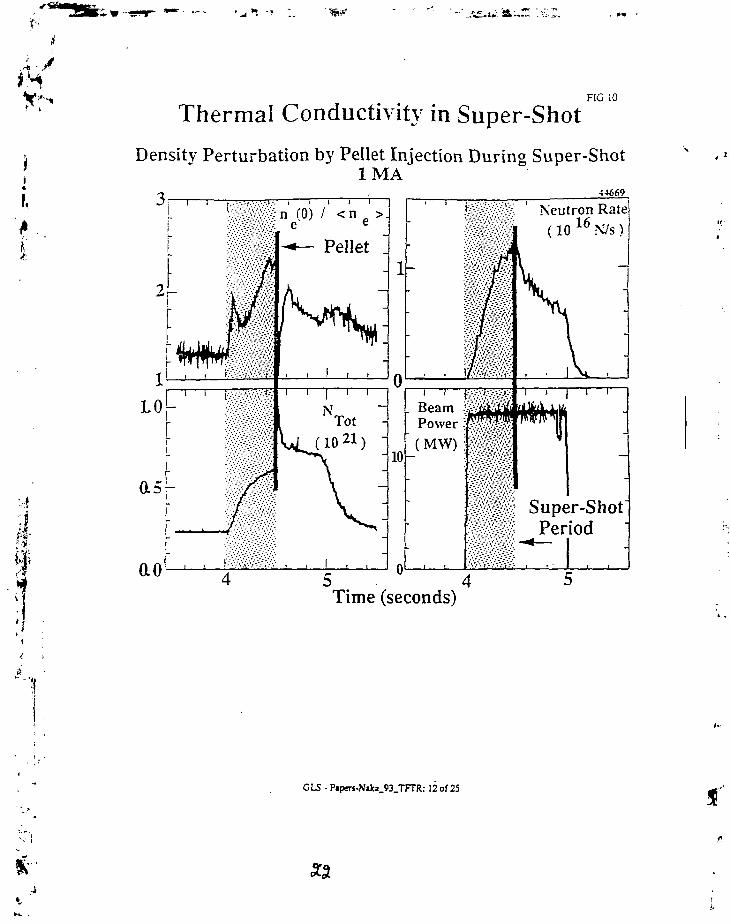
Thermal Conductivity in Super-Shot
Density Perturbation by Pellet Injection During Super-ShotIMA
3rn (0) / <n >.
e e
Pellet .
ao^
Neutron Rate(10 1 6 N/s )
Super-ShotPeriod
o5 4Time (seconds)
CIS • PapeT-s-NaJc»_93_TFTR: 12 of 25

¥
I
RG 11
Thermal Conductivity in Super-Shot
Pellet Perturbation Broadens Density Profile with LittleChange in Temperature Profile Shape
r T i ' i ' i • i • i * i *
G & t -480Pciici ».iy5
a- • - - A <,.:?2t>X X 4 .535a -a 4.555
O 4.575
Minor Radius (m)
CLS - Pipers-N«ki_93_TFTR: 13 of 25

FIG i :
iif
Thermal Conductivity in Super-Shot
•n- Driven Well Above Nominal Marginal Stability FollowingPellet Perturbation
Hahm & Tang (slab)
Romanelli (toroidal)
Xu &. Roscnbluth(toroidal gyrokinclic
code)
•4 .6

}
I
FIG 13
Thermal Conductivity in Super-Shot
%j Unchanged
Comprehensive Linear Numerical Calculation in toroidalgeometry using experimental parameters indicates
quasi-linear transport level not changed by perturbation
!
100 j
N 10H
(b)
I I I I I I I I I I I I I P
4.45 4.50 4.55Time (sec)
4.60
1
'•A
GLS - Paper5-N»ka_93_TFrR.-15 of 25
SLB

r j
II:
Improved Core Confinement RG !-a
Improved Core Confinement Observed FollowingProduction of Peaked Density Profile by Pellet Injection
o
Tot
i i i
_n e(0)
(10 20)
05 I I I
j i i i | i i i i
54418
Pellet
MM
ICRFPower
- (MW)
i i i i I i I i I
01 0
I I I I i I I I 1 I i I : ' !m
1 ' ' I I 'T (2.7m)
e(keV)
i i i i
I n (0) / < n ' >e e
i ' i i i 0 ' ' ' i
3i i i
0
i i i I i i i r
• Neutron Rate
- (10^N/s)
3 Time (seconds) 2.5
GLS • Piper5-N«ka_93_TFTR: 16 of 25

I
r •
ill
10
CM
V)
o
3 ^ -
CD
Q
°'o.oo
Improved Core Confinement
Neutron Rate Enhanced
Peak Neutron Emission Ratefor TFTR Pellet + ICRH
Ub
3He Minority - 2.1 MA j3He Minority -1.4 MA \H Minority -1.8 MA !No Pellet - 2.1 MA !No Pellet-1.4 MA jNo Pellet -1.8 MA |
1.00 2.00 3.00 4.00 5.00 6.00 7.00
Ptot (MW)
GLS - P»pers-N»ki_93_TFTR: 17 of 25

FIG 17
Improved Core Confinement
Appearance of Weak Core MHDCan Limit Duration of Peaked Density Profile
6I
1
•s r
L2 h
Neutrons / secao'V)
ir
T e(keV)
54418
Major Radius2 . 7 62 •
2 . 5 Time (seconds)
5441S ^
3 . o
Niki_93_TFTR:20of25

X"'
1
Improved Core ConfinementComparison of Central Pellet and Off Axis Pellet
Perturbations
FIG ISa
5I ' I ' I ' I ' I ' ' ' J
0
3
-i _
1 1 ' 1 ' 1
- Neutron Rate(1014N/s)
- 54418
\ IPellet /
J
67962-
, 1 , ! .
2.4 2.6 2.8Time (seconds)
3.0 io isMajor Radius (m)
• ' ; ; •
GLS - P»pers-NjJca_93_TFrR: 21 of 25

m
I,
Improved Core Confinement
Comparison of Central Pellet and Off Axis PelletPerturbations
FIG lSb
2.0 2.5 3.0
Time (sec)
1
o0 . 0
544182.7 - 2.83s
1 .0
GLS - Papcrs-N»ki_93_TFTR: 22 of 26

M
I:
DT Phase - Deuterium PelletsFIG 19
At High Ion Temperature of TFTR Ion Landau DampingDominates Alpha Particle Instability Threshold
PPPL#92X0302
0.3 0.4 0.5 0.6 0 .7 0.8 0.9
5 10 15 20 25 30
P (MW).b
GLS - Pipers-Niki_93_TFTR: 23 of 25

• / *
Ywm*
FIG 20
DT Phase - Deuterium Pellets
Use Pellet Perturbation to Access Regime of Lower IonTemperature but Significant Alpha Particle (3
I
2.0
I ' I
before and aftersawtooth at 3.5 s
time (seconds) scaled minor radius
Instability Damping Suppressed by Low Ti
Sawteeth delayed or suppressed
CLS - Papers-Niki_93_TFTR: 24 of 25

JIAEA Technical Committee Meeting on Pellet Injection
at Naka Fusion Research Establishment JAER1, May 10-12,1993
HIGH-PERFORMANCE JET PLASMAS WITH PELLET INJECTION
P.H. Kupschus. S. Ali-Arshad, B. Alper, B. Balet, D.V. Bartlett, L. Bay/or(2). M.Bures, CD. Challis, S. Corti, A. Edwards, L.G. Eriksson, R.D. Gill, C. Gormezano,
C.W. Gowers, M. v Hellermann, T. Hender(1), J. Jacquinot, H. Jaeckel, K.Lawson, H.W. Morsi, J. O'Rourke, F.G. Rimini, G. Sadler, G.L.Schmidt(3), P.Smeulders, D.F.H. Start, D. Stork, P.M. Stubberfield, A. Taroni, F. Tibone, B.
Tubbing, W. Zwingmann
JET Joint Undertaking, Abingdon Oxon 0X14 3EA, UK(1) Culham Laboratory, (2) Oak Ridge National Laboratory,
(3) Princeton Plasma Physics Laboratory
1. INTRODUCTION
At the last IAEA Technical Committee Meeting at Gut Ising ,'n October 1988, JET reported on thegeneration of confinement improved PEP (Pellet Enhanced Plasmas) modes by early injection of 4 mmdeuterium pellets and subsequent central heating with about 8-10 MW of Ion Cyclotron Radio frequencyHeating (ICRH) or combined ICRH/Neutral Beam Injection (NBI) Heating in otherwise L-mode type 3 MAdischarges [1J. Since then, JET has expanded these pulses to higher plasma currents, higher additionalheating power levels, employment of larger pellet size and particularly has combined the PEP modeswith H-mode plasmas (1990/91) obtaining transiently plasma performances approaching those of the bestcompeting scenarios [2,3]. Essentially this paper reports is an excerpt from [3] expanded by more recentexperiments and findings; it does not intend to give a full review of the JET pellet experiments nor even ofthe immense variety of the PEP-mode phenomena. The evaluation of the pellet data is ongoing and hasallowed some insight into the reason for the PEP confinement and its transient nature:~The JET pellet database contains a good 200 shots with pellet injection of which about 120 show clear PEP indications; itsreview has revealed some trends which are now being followed up.
2. EXPERIMENTS AND RESULTS - 4 MMPELLETS
The combination of PEP- and H-mode wasobtained by injecting 4 mm pellets early into initially3 to 3.6 and later 4 MA X-point discharges and byimmediately applying cen.tral ICRH heating in theorder of 8-12 MW into these non-sawtoothingplasmas. Usually, the PEP mode starts soonfollowing the injection very closely followed by theonset of the H-mode and the combination reachesits highest performance level in somewhat less than1 second which then persists for up to .6 s before theplasma falls back, sometimes featuring significantMHD activity, into the H-mode'state. One of thebetter examples is shown in fig. 1 for pulse # 22490.The X-point configuration is formed immediatelyafter the end of the current rise to 3 MA and a pelletis injected soon after and well before the onset ofsawteeth. The pellet creates a peaked density profilewith a central value of 1.6.1020 m"3. The pelletinjection is immediately followed by additionalheating on a level of about 8-10 MW of ICRH (10-15% hydrogen minority and central resonanceposition). This leads in less than 1 second totemperatures equally for electrons and ions of about9-11 keV at a central electron density of 7.1019 nr3
and a central electron pressure of up to 1.2 bar at
15
itFig. 1: Time history of pulse # 22490
This work has been performed under i collaboration agreement between the JET Joint Undertaking and the US Department of Energy.

r' « •
She time of the maximum D-D neutron rate of 1.1016s'1. 80% of these neutrons are of thermonuclear origin.This is clearly (he highest observed thermonuclear neutron rate on JET for plasmas with Tj = Te . Themaximum value of the fusion product no(O)»TE«Tj(O) is in the range of 5-7.1020 m'3«s»keV and is among thehighest seen on JET. After about .5 seconds an L to H transition takes place, as can be seen from thetypical signature of the edge Da light and the total plasma energy now reaching 7-8 MJ. The plasma is in thecombined mode for about .5 s, then the PEP-mode terminates and the plasma adopts ordinary H-modebehaviour. The plasma is not saw-toothing before or during the PEP phase, nor in the subsequent H-rnode.In fig. 2 the peak neutron production rate of L- and H-mode plasma with and without PEP-mode is plottedversus plasma energy, demonstrating that the PEP H-modes are typically a factor of 5 better than theordinary H-modes. They also extend the trend curve of neutron production rate by a factor of 2 ascompared to the limiter PEP pulses (see also fig. 6 for a more up-to-date ensemble of PEP shots). It shouldbe remarked here that the higher neutron rates of the PEP + H-mode shots in comparison to the PEP + L-mode shots are likely to result from the higher ion temperatures which may be due to the betterconfinement. However, the PEP H-mode experiments were also conducted with a better ion heatingefficiency of the ICRH because of higher H minority fraction: PEP L-modes with < 5 % of H with about 30 %against 10-15 % of H with about 50 % of power coupled to the ions.
I
I £. PEP-H-mode at maximum neutron raleI * PE P mode discharges alter decay of the pellet!* enhancement
o Limiter PEP-L-mode* Typical H-mode4 Typical L-moOe A
~ ID
\
I/ /Stored energy (MJ)
5 10 15
Loss Power (MW)
20
Fig. 2: Neutron rate vs plasma energy Fig. 3: Plasma enrgy vs power loss
In fig. 3 the normalised plasma energy content is plotted against the loss power for a similar selection ofshots, at the time of maximum energy; the lines indicate one and two times Goldstone confinement scaling.The PEP data in the figure contains both discharges with clear PEP H-mode signatures and discharges inwhich the H-mode signature is less clear (PEP H- or PEP elmy H-modes). The figure shows the globalenergy confinement of good PEP H-modes is comparable or slightly better than that of ordinary H-modes.The figure further shows in the transition to the solid triangles that the confinement of the H-mode thatremains after the decay of the PEP phase is similar to that of ordinary H-modes.
In the following experimental phase 1991/92 more experiments were carried out and the data base on4 mm PEP shots was widened (for 6 mm pellets see below). In particular, it could be shown that theadditional heating pulse can be delayed against the pellet injection for as much as 1 s and the PEPconfinement state is still established. Fig. 4 shows an example of a 3 MA pulse with Tj = T e = 16 keV byvirtue of good confinement in combination with relatively low density due to the time delay and very central

$*'•
' * '
n* 1 '%heating of ca 8 MW of ICRH (likely to have created a non-thermal ion population at this density) and 140keV NBI (previously 80 keV). The peak neutron rate for this shot is 1.2.1016 s'1.
Pulse No: 24352
S
0.8
0.4
2 0 ~ Pulse No: 26491i (6mm pellet)
' . 6 -
'S 1.2L
Enhanced coreconfinement phase
2.0 2.5 3.0 3.5' Radius (m)
4.0
Fig. 4: Time history of pulse # 24532 Fig. 5: Initial density profiles after pellet deposition
ft
3. AIMS, EXPERIMENTS AND PRELIMINARY RESULTS - 6 mm PELLETS
Since the attempts with 4 mm pellets (average ne increase of 2.7.1019 m-3) result in well-confinedcentral cores reaching out to about 1/3 of the smaller plasma radius - i.e. covering only about 1/10 of theplasma volume - it was hoped that 6 mm (average ne increase of 8.1019 m-3) would generate triangulardensity profiles with large density gradients throughout the full plasma cross section. This would permit tofind out whether the PEP confinement can be extended to larger plasma volumes, with thencorresponding increases in neutron rate and total plasma energy, or it would still be limited to a morecentral core because the shear cannot be made sufficiently low over the full volume (see chapter 5); detailsof the development of profiles would give further indications about the nature of the PEP-mode.
The operational problems with this scenario lie in the problem that on the one hand the central electrontemperature is not to exceed 2.5-3 keVto permit central deposition of the 6 mm pellet but that on the otherhand the total plasma energy at the time of pellet injection need to be sufficiently high - of order 3 MJ - toavoid a radiation collapse which will occur if the post-pellet electron temperature falls below ca 250 eV. ForJET this target plasma can only be obtained in an X-point discharge with modest amounts of NBI, precedingthe pellet injection and leading to a relatively broad electron temperature profile. .
Indeed, in 1992 the desired type of initial deposition profile with a peak value of around 2.3.1020 nv3 wasachieved in a number of cases in 4 MA discharges, and an example is shown in fig. 5 some 20 msecafter injection in comparison with a corresponding typical 4 mm pellet deposition profile, (note: The 4 mmdeposition profile in the small insert of fig. 4 is atypical in its triangularity but the further development ofthisdensity profile may indicate a preference of the plasma to develop a central core only). A total of nine 6mm pellet shots approaching the above initial deposition profile were successfully heated with varyingcombinations and levels of ICRH and NBI (140 keV ). Commonly they feature a central density decaysimilar to those of the 4 mm shots and develop in a combined PEP- and H-mode plasma with about 10 MJof total plasma energy at only Tj s T e = 5 keV; the ones with predominantly ICRH heating around 10 MWachieve a D-D neutron production rate of 6.1015 s'1 - almost half the values of comparable 4 mm shots atmuch higher temperatures. Although the detailed code evaluation of these shots is still outstanding theirglobal data seem to suggest that they show a high performance but not to the extent that the abovequestions can be answered. Their total particle content is higher than that of the 4 mm plasmas andtherefore regarding the applied power the-ion temperature and neutron yield are low despite favourable nt

"T-values. Fig. 6 shows the neutron production rate plotted versus the total plasma energy of 6 mm pelletshots in comparison to an updated data set of 4 mm shots. Future experimental work will also have toconsider trie merits of an intermediate pellet size for which the JET additional heating capability would bemore appropriate.
. • *
= ' 5 -
: IC- IC»Nk30%.. IC+NI. NUIC<30%
MlSolid: 6mm pellet
4 6
WDI4(MJ)
10 121 -
PEP l-mode
0.8
Fig. 6: Neutron rate vs plasma energy Fig. 7: Eff. heat conductivity vs radius
4. MORE DETAILED EVALUATIONS
The confinement features'found in L-mode and H-mode PEP pulses alike suggest that the PEP mode ismore or less independent of the state of the background plasma it is superimposed upon. During theoverlapping period of the PEP- and H-mode, local transport calculations using the FALCON and TRANSPcodes have shown central values of (r s 0.4 a) of the electron diffusion coefficient De = 0.1 m2s-1 and theeffective heat conduction coefficient Xeff = 0.5 m2s"1 (these central values are also typical for the old limiterL-mode PEPs); outside the central region Xeff values characteristic for H-modes are found in the range of 1-2.5 m2s'1 as shown in fig. 7. Code calculations for some early shots show consistency with thethermonuclear neutron production rate up to a point, however in many cases it is observed that the neutronrate decays significantly before the termination of the PEP phase. This can be explained by three possiblecauses or their combination: decaying central density, deuterium dilution in combination with impurityaccumulation during the good confinement, and in some cases degrading confinement due to MHD activity.Indeed, there is experimental evidence for all of them in such an abundance that it is difficult to catalogue.Statistically of the 120 or so PEP shots only around 50 are terminated by MHD events, about one third ofthose by locked modes and ELMs, the remainder by n = 1, 3 and 2 modes (according to their frequency).Regarding the impurity / dilution issue the cataloguing is still incomplete but there are pulses withpronounced impurity accumulation close to that expected by neo-classical theory as well as cases withstagnant impurity contents or even expulsion of impurities without termination of the PEP-mode for aconsiderable period of time. Since any of these issues can also influence the duration of the PEP-mode (orfor that matter of the combined PEP- and H-mode) it is not clear from the statistical evidence that the PEP-mode needs to be transient because there are a few pulses with a duration of the mode for a few seconds.This diversity may have to do with the subtleties of the generation and decay of the PEP-mode assuggested in the next chapter.

5 INTERPRETATION AND CONJECTURES.
Our level of understanding of the PEP mode - in particular why the high confinement mode develops inthe centre, gently deteriorates or often ends in spectacular crashes of central electron and ion temperaturesas well as neutron rates - is still roughly that of [3] , some of it still speculative. Earlier work has beenperformed considering ballooning [Galvao, 1988] or infernal modes [Charlton, 1991] due to high pressuregradients to be responsible for the observed MHD phenomena. However, in many cases PEP modesdisplay similar MHD phenomena without having reached similarly high levels of pressures/ neutron rates orgradients. This suggests that the current density and q-profile might be the dominant variable in the stabilitygame. We have diagnosed by magnetic analysis of developing instabilities for a particular pulse theexistence of a q = 1.5 surface inside a q =1 surface [4]; this is supported by soft X-ray diagnostics; therefore,a region of negative shear dq/dr<1 must exist. This non-monotonic q-profile can be created during the coldshock during pellet injection expelling a central portion of the current; this particular profile is then aided bythe bootstrap current due to the steep density gradient dne/dr = -(5 to 1.1020 nr4) concurrent with, the pelletdeposition and increasing with the temperature gradient due to the centrally applied heating,Eventuallyfreezing the current density profile when the temperature becomes sufficiently large. Calculations of thebootstrap current densities indicate a value of the order of 1 MAnr2 in the region of r = 0.4 a, comparable tothe ohmic current density. It has been speculated that the enhanced central confinement is associated withthe reversal of shear. Simulations using the Rebut-Lallia critical temperature gradient model outside andassuming neo-classical transport inside the negative shear region show qualitative agreement with theexperiments, in the time window between the pellet injection and the onset of MHD phenomena. Thesesimulations were done by treating the ions neo-classically in the core and assuming the electron heatconduction coefficient either itself neo-classical or equal to that of the ions. A current density distribution notchallenged by high pressure or pressure gradients might also survive for quite some time explaining theperformance of pulses with delayed onset of the additional heating pulse. On the other hand, if the plasmaperformance, i.e. the pressure or pressure gradients are limited by-other effects like dilution and impuritiesor the current distribution is influenced by other phenomena like current drive, plasma rotation or electricfields then the MHD stability might not be challenged and this would explain the more gentle roll-overappearance of the other shots. Accepting these hypothetical interpretation, the key to a more tailoredbehaviour of the PEP-mode would lie firstly in the ability to better shape the onset of the desired currentdistribution and then secondly to maintain it during the heating phase to preferably last into the flat top.Measures for the first class are to create a higher q on axis by advancing pellet injection earlier into thecurrent rise (at lower internal inductance Ij), work at higher toroidal field (limited in the case of J E ^ or shapethe early current distribution by non-inductive current drive. Measures for the second class are theimmediate freezing of the desirable current density profile once achieved by raising the electrontemperature as fast as possible after pellet injection and using active means for desirable corrections of thecurrent density profile by either density profile shaping (NBI and pellets) or selective current drive (e.g. NBIor application of radio frequency in the form of lower hybrid or ICRH phased antenna configuration). Any ofthe tasks is experimentally difficult because it means guiding a plasma with an inherently unstable currentdistribution profile through the pitfalls of onsets of rustabilitiesm the absence of (preferentially real-time)diagnostics permitting to tightly monitor and possibly feedback control the q-profile.
6. CONCLUDING REMARKS
Apart from providing an interesting and potentially useful insight into the physics governing the centralcore of a tokamak plasma, the PEP-mode may have a technical application as an operational start-up modefor a future fusion reactor with a minimum additional heating power or at least a minimum additional heatingenergy before its plasma after ignition is permitted to relax into a mode without impurity accumulation andwith suitable particle loss for ash removal. For this to happen it will require still a lot of work and it wouldalso be necessary to tailor the PEP-mode for a ramp time period sufficiently long to adapt the poloidal fieldto the rapid change of JJ. -
3 ?

- - . Kjiscnus e: a!., " JE; f.'.Lr!:i-Pe!let Injection Experiments", Pellet Injection and i oroiaalcor.fir.ernent. Proceedinas of IAEA Technical Committee Meeting, Gut Ising, 24-26.10.1988. IAEA-T5CDOC-534, 1989
S.J.D. Tubbing et si., "H-Mode Confinement in JET with Enhanced Performance by Pellet PeakedDensity Profiles", Nuclear Fusion, 31_ (5), 839-850 (1991)
=.H. K-j Gchus et al., "High Thermonuclear Yield on JET by Combining Plasma Performance of ICRH-Heated, Pellet-Peaked Density Profiles with H-Mode Confinement", 18th EPS Conference onCont'dled Fusion and Plasma Physics 1991, Europhysics Conference Abstracts, 15C (I), pp 1-A
!.'.. Hugon, et al., "Shear Reversal and MHD Activity during Pellet Enhanced Performance Pulses inJET". Nuclear Fusion, 32 (1), 33-43 (1992)
Ift
i

IAEA Technical Committee Meeting on Pellet Injectionat Naka Fusion Research Establishment JAER1, May 10-12, 1993
f / ^ Pellet Injection Study in JT-60U
R.Yoshino and JT-60 Team\
\ ' Department of Large Tokamak Research, Naka Fusion Research Establishment
j Japan Atomic Energy Research Institute
I Naka-machi, Naka-gun, Ibaraki-ken, Japan
V Preliminary experimental results of pellet injection in JT-60U are> presented in this paper. 1) Particle fuelling by the pellet injection modified
the NB heating profile and changed the resultant pressure profile. Thismodification avoided fjp-collapse and produced H-mode transition in high f)pexperiments. 2) Combination of the monster sawteeth produced by 2.5MWICRF central heating and the central particle fuelling by the pelletinjection improved the energy confinement a little. 3) Pellet injection withthe following NB heating suppressed the locked mode. 4) A central whitering or a hollow white ring observed in a plasma just after the pelletinjection was measured by a tangential visible TV, and agreed well with thelocation of the particle fuelling.
1 . I n t r o d u c t i o nExperiments of the pellet injection in JT-60U started last October. A
pneumatic pellet injector with 4 pellets has been equipped at 15cm above amidplane. Diameter of each two pellets are 3mm and 4mm. Speeds o f themare <.1.76km/s for deuterium pellets, and £.2.02km/s for hydrogen ones. Thefuelling efficiency of pellets into the vacuum vessel was arouod 6 0 - 7 0 % [ l ] ,Pellet injection experiments of 70 discharges have been tried until now tostudy the plasma performance in various types o f experiments such as H-
• * mode and/or high pp with NB heating, monster sawteeth with ICRF heating,| and LHCD. Optimization of the pellet injection has not been completed yet
K|# due to very small shot number. However some interesting phenomena were• *$• observed as presented in this paper. They are the avoidance of high Pp-O< collapse, the production of H-mode transition with a rise of the edge ionj$ temperature, the suppression of the locked mode, the enhancedii| improvement of the energy confinement with the monster sawteeth, and TVv | measurement of pellet fuelled plasmas..1 Diagnostics for pellet experiments are two channels of FIR<| interferometer, 64 channels of a soft X-ray array, ECE michelson and' polychromator, and a tangential visible TV.
'; 2. Combination of Pellet Injection with high f)p plasma•?.,j •* High Pp experiments were performed with a plasma volume of -50m^,
i • placing the plasma center on the lines of perpendicular neutral beams[2].j High power deuterium NB heating with <.33MW was performed in recentI t', experiments and the central ion temperature increased up to 40keV. In) '•- these experiments Pp-collapse limited the improvement of the energy' •• confinement and the rise of the neutron yield. The strong in-out asymmetry]r v were observed in the fluctuations of the electron temperature measured by
, . '• ' ECE polychromator just before a pp-collapse. This asymmetry suggests. •* ballooning or infernal instability[3]. Then some modifications of a pressure
profile and/or a plasma current profile may avoid the pp-col lapse.

•mar'.
A typical case of the fSp-coIlapse is presented in Fig.l(a). Onedeuterium 3mm1? pellet is injected at 4.95 s, but the increase in the plasmadensity is very small owing to the breakup of the pellet. Edge iontemperature dose not rise in spile of NB heating, and Pp-collapse occurrs att=5.95s. A highly peaked profile of the ion temperature measured by thecharge exchange recombination is observed with the low peripheral iontemperaiure as presented in Fig.2 by a dotted line. On the other hand onedeuterium pclict of 3mm'!' with a pulse gas puff of 20Pam^/s x O.lscc wasinjected to an OH plasma just before NB heating as presented in Fig.l(b). Thepenetration depth of the pcjlet is shallow with 20% of the plasma minorradius. The edge ion temperature rises just after the pellet injection due to20MYV NB heating with perpendicular beams, and reaches 2kcV at the endof ihc decay of the peripheral density (t=5.2 s). The particle fuelling by thepellet injection increases the edge density, that raises the deposition powerof NB heating at the plasma peripheral region. The rise in the iontemperature continues after the drop of the plasma density, and H-modctransition is observed at 4.5keV (t=5.66 s). Howeevcr the H-mode phasereturns to L-mode very quickly, and the confinement improvement isterminated. Clearly pp-collapse is suppressed by the pellet injection, and theenergy confinement is improved a little from the shot with Pp-collapse aspresented in Fig.I(a). High peripheral ion temperature of 6~9kcV isobtained during the H-mode as presented in Fig.2 by a solid line. Anincrease in the pressure at the peripheral region and a decrease in that atthe plasma central region, those were measured by soft X-iay measurement,reduced the pressure gradient around the half radius and avoided the Pp-collapse.
_ 2- -
010'
-30 ^
, rPNeiang • i !
Pp-collapse ~~s | ?
Neutron ; 2 5
Fig.l Time evolutions of high jip discharges.(a) Not-enough particle fuelling justbefore NB heating causes pp-collapse.(b) H-mode is observed for the pelletinjection with the intense gas puffing.
Fig.2 Ion temperture profiles for Fig.l(a)and (b).
01 - ~•D >6> O
;io «r
04.5
fast rise o) T | e d 9 e
lel \ . _/ ' -v , (b) i I *5.5
TIME (SEC)6.5 —
50
40-!..
30-H-
20-
10
0
just before Pp-collapse JE17302 t=5\80s !
/ "i* ' •'
' \ * -
•, '•, shallow pellet .'v fuelling 3mm$yV ET7305 l=S.85s -
0.5 1.0r(ml

* r - < •!
nIP,
5
>•5
BO
0)
•o
H"
2
rb.U
Nit
]
<
2
010
00
0- 1 0
o-
"ip
Gas Puff
Jnedl
4.5
PNB
Wdia
-^—. —
. — - —5.5
TIME
.pNBtang
5.36—Vv.^ ^ "v
" Neutron~*~*—'—'—'—lTTt~~
H-mode \
' T
(SEC)
.'30
JO
J 5j
jo—i
J5010
~10
Joe.s
l!2<o3 Oo> *> -
8it—
ioo
Yie
ldut
ron
a
6
5
4
3
2
1
Q
pulse gas pullPNB=33MW
-• 1993o 1992
•6
PNB
1 i• • •
3mm* pelletPNB=33MW'
4 pellet=15MW :
. . f . . . 1
2 4 6 8 10
Stored Energy (MJ)
Fig.3 Time evolution of a high Pp discharge Fig.4 Neuton yields and plasma storedwith a intense pulse gas puff just energies of high pp discharges,before NB heating.
1
In the optimization to get high performance plasmas, a pulsedeuterium gas puff of 20Pam3/s x O.lsec alone was tried, and the delayed H-mode transition was obtained as presented in Fig.3. Plasma operations inFig.l(a),(b) and Fig.3 are almost same except the particle fuelling. Theneutron yield is the highest record of 5.63xlO^/s. The rise of the iontemperature is smaller than that with the pellet injection (Fig.l(b)), but ishigher than that without the pulse gas puff (Fig.l(a)). The return to the L-mode at 1=6.16 s with the flattening of a peaked pressure profile terminatesthe confinement improvement. The differences in the plasma performancesespecially in the ion temperature profile suggest that the pellet injection isa powerful tool to modify and optimize the pressure profile. Unfortunatelyfurther pellet injection experiments were unavailable by the broken of thecontroller of the pellet injector owing to too much neutron yield in theseries of high p"p experiments. Then the central particle fuelling in thesame plasma configuration with the high Pp experiment is planned in thenext experiment period. The plasma stored energies and the neutron yieldsobtained in the high (}„ experiment are presented in Fig.4. The upper of theneutron yield is limited by the high p p collapse. The stored energiesobtained by the combination of NB heating with the pellet injection and/orthe pulse gas puff are in the range of those obtained by NB heating alone.
The ELM-free H-mode was obtained with the injection of onedeuterium ^ m * pellet with following 15MW NB heating. 15MW NB heatingis higher than the empirical heating power threshold for H-mode transition(-13MW). The pellet penetration depth was about a half of the plasma minorradius. Time evolution of the discharge is presented in Fig.5. The L- to H-mode transition is observed at 1=4.24 s. A small drops in D a emissionsobserved at the main plasma and the divertor region, and then plasmastored energy and electron density increase gradually. ELM-free H-modc isobtained until 100ms after the termination of NB heating. The electrondensity of S.SxlO^/mS ; s higher than the empirical density threshold forthe transition from ELM-frec H-mode to ELMy H-mode as presented in Fig.6.The horizontal axis is a ballooning parameter corrected by the internalinductance Ij. The modification of the local current profile and/or pressureprofile may suppressed the activity of ELM. Study of the stabilizingmechanism of ELM by the pellet injection will supply some usefulinformation to understand the mechanism of ELM.

I.>.
i.
Domain ELM-free H-mode i
O.I 0.2 0.3 0.4 0.5 0.6Bl2/(Rq.i|J) x I,
TIME (SEC)Fig.5 ELM-free H-mode obtaied by the FiS-6 Threshold plasma densities of ELMy
pellet injection and following NB H-mode.healing.
3 . Suppression of Sawteeth and m=l modeIn JT-60, suppression of sawteeth and the m=l mode were obtained by
particle fuelling inside q=l radius with the central NB heating[4], and theconfinement improvement of 40% was obtained. Improved confinementinside q=l radius was the cause of this improvement[5]. When sawteethand/or m=l mode were observed, the improvement of confinement wassaturated or terminated. A numerical investigation of the current profilesuggested that q(0) was lower than 1.0[6], and the pressure profile wasmarginally stable against the ballooning instability[7].
Pellet injection was combined with the central healing by ICRFsecond harmonic minority (hydrogen) heating. Monster sawteeth withoutm=l mode were obtained up to 1.9 s with 2.5MW ICRF power heating. Atypical combination of the pellet injection with NB heating is presented inFig.7. One 4mm(i) pellet was injected to an OH plasma, and ICRF heatingstarted after 200ms. A monster sawtooth of 0.9s is observed with an increasein the electron temperature measured by ECE michelson. After a sawtooth-crash, the electron temperature rises to the same level with that just beforea sawtooth-crash. However the stored energy is degrade -10%. The peakingof the soft X-ray profile, that is obtained by an abel inversion of soft X-rayemissions measured by a pin-diode array, is degraded largely by a sawtoothcrash as presented in Fig.8. The central soft X-ray emission at t= l l s (at the2nd peak of Te(0)) is 60% of that at t=10.0 s (at the 1st peak of Te(0)). Soft X-ray emission is a function of n^-T^. Then a peaked density profile obtainedby a pellet injection is a cause of the confinement improvement. Furtherimprovement will be tried with increasing ICRF power up to 5MW.
T.(0)(k»V)
(MW)
0A.?
Wo,.(MJ|
toT (sec)
Fig.7 Time evolution of monster sawteethproduced by the combination of thepellet injection and ICRF heating.
Abif InwfJon of SX signals
5.-S0.5
Fig.8 Soft X-ray emissionprofile for each time "point in Fig.7.
'(pellet effect)
. , i l o o . " c I just before'. I 10.4 stc Monster SW*r ii.o »c 2nd peak
% posl-Monster SW.V \ ! | 10.«s tic
c : 0.4 s.6 o.a t 1.2p(m)

r A
r> n
i
Time Evolution
Soli X-ray Prolile
E17749
qejf=4.3
CENTEREDGE ""PELLET (b)
keV
)
Q
c•
co
4-
2
00.0
nmJ pellet inj. 3.939s: l=3.92s, pre pellet inj.; t=3.9Ss, post pellet inj.
E16506
(b)
. ': Pellet "
0.5 1-0r (m)
Fig. 10 Central fuelling. Fig.11 Shallow suelling.(a) TV measurement with a central (a) TV measurement with a hollowwhite ring, (b) Time evolution of a white ring, (b) Change of the Te profilepeaked emission profile of soft X-ray. by a pMa
6. SummaryPreliminary experimental results of the pellet injection from 70 shots
obtained in JT-60U are presented in this paper. Modification of the NBheating profile and the pressure profile in high Pp experiments wasobtained by the shallow pellet injection with a pulse gas puff to an OH targetplasma just before NB heating. The Pp-collapse driven by some ideal modeswas avoided by a little broader pressure profile. The increase in the iontemperature and the pressure at the peripheral region caused the H-modetransi'ion. Same discharge scenarios except an intense gas puffing alonedelayed the H-mode transition with much improved confinement, and madeit possible to get highest neutron yield of 5.63xl0^/s in DD reactions.Combination of a monster sawtooth produced by ICRF central heating andthe central particle fuelling by the pellet injection improved the energyconfinement with 10% by the peaked density profile. Further improvementis expected with increasing ICRF power from 2.5MW to 5.0MW. Combinationof the pellet injection and the following NB healing suppressed the lockedmode. The stabilizing mechanism is not clear yet. The increase in the localtoroidal rotation may be one possibility. The visible TV measurement of thepellet injected plasma is useful to investigate the fuelling location. A whitecentral ring was observed for the central fuelling, and a hallow white ringwas observed for shallow fuelling. Brensstrahlung may be a cause of theseradiation.

."•* \_f
.kr «
Future plan of pellet injection experiments are following. First priorityis the improvement of the energy confinement «i! Tj(0)=10~25kcV withsuppressing sawteeth, m=3 mode, and pressure driven modes. The pelletfuelling profile, the NB healing profile, and the target plasma currentprofile will be optimized in this experiment. The compatibility of the pelletinjection with ELMy H-mode and the suppression of the locked mode by thepellet injection will be investigated to support the design of fusion reactors.
REFERENCES[1] H.Hiratsuka, ct al., "Pellet Injector in JT-60U" in this meeting[2] S.Ishida, et al., "Enhanced Confinement of High Bootstrap Current
Discharges in JT-60U", 14th International Conf. on Plasma Physicsand Controlled Nuclear Fusion Research, Wurizburg, IAEA-CN-56/A-3-5 (1992)
[3] Y.Neyatani, et al., "MHD Behaviors in High pp and P]\j Discharges in JT-60U", will be presented at 20th EPS Conf. on Controlled Fusion andPlasma Physics, (1993)
[4] R.Yoshino, et al., Proc. Tech. Comm.Mlg Gut Ising.1998, IAEA-TECDOC-534.IAEA,Vienna (1989)
[5] K.Shimizu, ct al.. Nuclear Fusion, 31 (1991) 2097[6J R.Yoshino, Nuclear Fusion, 29 (1989) 2231|7] T.Ozeki, et al., Nuclear Fusion, 31 (1991) 51[S] T.N.Todd, ct al., "The effect of Error Fields on Tokamak Stability", 14th
International Conf. on Plasma Physics and Controlled Nuclear FusionResearch, Wurtzburg, IAEA-CN-56/D-l-l-l(c) (1992)
[9] R.J.La Haye et al., Phys.Fluids B 4 (7) (1992) 2098[10] G.M.Fishpool, et al., Proc. of IAEA Technical Committee Meeting "Avoidance
and Control of Tokamak Disruptions" Culham Lab. (1991) 84(IIJ Y.Kamaria. et al., "MHD Activities in Pellet Injected Discharges in JT-60
and JT-60U", in this meeting.

" --I^.J* -fit—.
OVERVIEW OF THE PELLET INJECTION PROGRAMME OF TORE SUPRA
M. Chatelier, A. Geraud, H.W. Drawin, B. Pegourie", J.M. Picchiottino, C. Desgranges^ Association Euratom-CEA/DRFC CE-Cadarache
, 13108 Saint Paul-lez-Durance, France
I C.A. Foster, L.R. Baylor, A.L.Qualls, S.L. Milora, M.J. GougeJ Oak Ridge National Laboratory
. * Oak Ridge Tennessee 37831-8071, USA
f 1. I N T R O D U C T I O N* The primary aim of Tore Supra is to achieve long pulse operation and to study the
physics of steady state thermonuclear plasmas. A centrifuge pellet injector delivering upto 100 pellets at 600m/s has been delivered by the Oak Ridge National Laboratory withthe purpose o f controlling the plasma density over 20-30 seconds (5-3Hz) in differentsituations. Encouraging results have been obtained in 1991-92 [1,2] with regards to thedensity limit, the ergodic divertor operation and the compatibility with lower hybridcurrent drive (notched operation). An improvement of the pellet feed system is underwayat Oak Ridge to reach the high reliability required for maintaining steady state conditionsover long pulse durations [3] . This new system will be implemented on Tore Supra laterin 1993.
Developpements of two stage pneumatic injectors for J E T have been undertakensome years ago by the Service des Basses Temperatures of C E A at Grenoble (France). Atwo stage gun has been installed on Tore Supra in 1992 with the aim of studying pelletablation scaling with velocity and deep fuelling. Velocities up to 2 .4km/s have beenobtained on plasma for unprotected deuterium pellets [4] . Pellet penetration studies havebeen made in ohmic conditions to assess the validity of ablation models over the widest
'A range of velocities reached so far and for electron temperatures in excess of 2keV [5] ."'. I We briefly review the main results which have been obtained with the centrifugef\\- injector and report on more recent experiments made with the high speed injector in? vj'. different experimental conditions.
v
2 . M U L T I P E L L E T E X P E R I M E N T S :Long pulse steady state operation of thermonuclear grade plasmas requires to ;
succeed in operating several devices aimed at controlling jointly the exhaust from theedge and the source to the plasma of heat and matter. Actively cooled p u m p limitershave been successfully used sustaining average power fluxes up to 3 M W / m ^ [6] andproviding (separately for the moment) 5-10% exhaust efficiencies for deuterium [7] .Supplementing gas injection, repetitive pellet injection is achieved with a centrifugepellet injector delivered by the Oak Ridge National Laboratory and having a capability ofa hundred 600m/s pellets. High power I C R H and L H C D a re used to heat the plasma anddrive the current. An ergodic divertor is used to control the plasma edge by reducing the "local electron temperature and preventing impurity penetration to the p lasma core [8 ] .All these systems need further technological improvement , in addition to improvedphysics understanding, to reach the high degree of reliability required to achieve longpulse operation of a controlled plasma. Dedicated efforts a re underway for each of them *"'and in particular for the centrifuge injector which a re presented at this meeting [3 ] . •"*Among the different physics results obtained so far, those concerning the density limit

r M
I
and joint operation of the pellet injector with the ergodic divertor or lower hybrid wavesare of particular interest for the realization of controlled long discharges.
-Density limit [1J: current disruptions are triggered when the input power is 100%radiated. When deuterium gas injection is used, the radiated power increases almostlinearly with the plasma average density and equals the ohmic power for values of Mq oforder of 7-8 (M= <n e >R/Bx n r 2 T ' ' and q is the edge value of the safety factor). Incontrast helium plasmas of much larger density can be built (Mq> > 12) with a radiatedpower almost constant over all the density range (Prad ~ 30%). Pellet injection exhibitsthe features of helium injection, i.e. no change in the proportion of radiated power whenthe density is increased till a dramatic radiation enhancement occurs at Mq«=8-10. Theseresults are depicted on figure 1. In these experiments, the wall status plays a key role: aslong as wall pumping is effective, the density does not grow at the edge for a givenplasma mean density and the edge radiation is not increased. When wall saturationoccurs, the edge density increases in an uncontrolled way and the power radiated at theedge cannot be compensated by the heat flux from the plasma core, giving birth to acurrent disruption. The difference observed between gas and pellet fuelled experimentscan be explained by the difference in fuelling efficiency of the two methods: more gas isrequired than pellet atoms for a given core density so that the edge density and theradiated fraction of the power are larger in the former case. In any case, this illustratesthe need for active pumping to perform density control over long time scales.
Prad ' PohmVad ' ohm
1.0
0.75
0.5
0.25
0.0
Pelletinjection
Gas injection,
O deuterium• helium
€ <
2.5 7.5 10 2.5 7.5 10
Mq Mq Pu19m"ZT~1)
Figure 1- Ratio of radiated to input power for pellet or gas (He or D2) helleddischarges as a function of the Murakami parameter
-Ergodic divertor [8]: A multipolar winding produces a peripheral layer where themagnetic field lines are stochastic and where the electron heat diffusivity is enhanced [8].In this layer, the particle transport accross the field lines is also affected and efficientscreening of impurities or of hydrogen isotopes takes place. This is why the fuellingefficiency is so low for gas puffing through the ergodic layer (<5%). In suchconditions, the input power is radiated at even lower plasma densities than in the cases

* r -
ii
I.
\
depicted on figure 1: Mq=6irr2T~1 instead of 9 for deuterium, and Mq=15-20nr2T-1
instead of 25 for helium. When pellet injection is used, the penetration as well as thefuelling efficiency are quite similar to those obtained without ergodic divertor. For agiven plasma mean density, the fraction of radiated power is larger with the ergodicdivertor than without; this radiation is located at the periphery of the plasma [9]
-Lower hybrid current drive [2]: long pulse operation requires high power hybridwaves to generate the plasma current. The fast electron population created by thesewaves, in the range =100keV is particularly detrimental for pellets since a directinteraction takes place with the ice making ineffective the neutral cloud protection. Thepellet material is deposited at the plasma edge and resembles gas puffing. The fuellingefficiency drops down to values of order of 10%. Notching the RF has been succesfullyused, allowing restauration of both the penetration depth and the ohmic-like fuellingefficiency. On figure 2 is shown the penetration depth for different densities and deadtimes At; exploration of high density and RF interruptions shorter than 30ms should bepursued. However, this technics has a significant cost in terms of magnetic fluxconsumption making attractive deeper penetrations obtained by increasing the pelletvelocity (see section 3).
penetration (m)
0.3
pellet
• <ne>=2.0ia19m3
f- <ii l.>*l.Bi019in'3
o <ne>=1.4 1D19m'3
20 40 £0
At(ms)
80
Figure 2- pellet penetration as a /unction of the delay At between the LHCD switch offtime and the pellet time for several densities.
3. HIGH SPEED PELLET INJECTION EXPERIMENTS:A two stage gas gun has been built by SBT-CEA at Grenoble and implemented on
Tore Supra to study pellet penetration and ablation at the highest achievable velocitycompatible with as reliable as possible existing technology [4]. The pellets are formed by"in-situ condensation" in the gun barrel (diameter 3mm), without sabot protection, andaccelerated by the pressure front generated by compression of the gas contained in thesecond stage of the gun. Two tanks in series (equipped with primary and secondarypumping units respectively) and a fast shutter located in between the two tanks efficiently

iI
I
prevent the propellant gas from reaching the gate valve of the torus. In 1992, maximumvelocities of 2.4km/s were achieved and pellets at this velocity injected in Tore supra.Improvement of both the mechanical accuracy of the gun and the cleanliness of theresidual vacuum in the cryogenic cell allowed to reach 3.4km/s on a test bed atGrenoble. Such velocities, which have been reproduced at Cadarache, will be tested onplasma in 1993. We report hereafter on the results of 1992 at velocities up to 2.4km/s[!0J. The pellet velocity can be varied between 1 and 2.4 (3.4) km/s by changing thefilling pressure in the first and /or second stage of the gun. The pellet size can be variedfrom 2 l(pO to 1.6 Kpl atoms by modifying the condensation time and temperaturegradient around the cold cell. In addition to ablation studies, this fast pellet injectorallowed to reproduce various features of core pellet fuelled discharges such as snake-likestructures or PEP-like improvement of the central confinement and to confirm departuresof the matter deposition profile with respect to H a light profile observed on TFTR andJET. We briefly discuss some of these results hereafter.
-pellet ablation at high pellet velocity [5,10]: operating at low density, in ohmic
calculated penetrations (m)D.M
fi.BO
0.30S.Gfan|E
OMGS-okMie+ NGSHCRH• NGPS-ohmic
Hi 030 1.40 0.51 0.SI 1.71 0.80 IM
measured penetrat ions(m|
Figure 3- calculated versus measured penetration depth fyr pellet velocities rangingfrom 0.6km/s to 2.4km/s in ohmic and ICRHplasmas.
conditions has allowed to extend the available data base for penetration depths up toelectron temperatures of *4keV for pellet velocities from 0.6-2.4km/s injector. Themeasured penetration depths compare well with the NGS model predictions [11]. Arefined NGPS model, developped at Cadarache [5], on the basis of the standard NGPSmodel [12] has also been tested. This model computes self-consistently the plasmachannel radius and accounts for the heating of the neutral cloud by the cold plasmasheath. The agreement between experimental and calculated values is quite satisfactory

S :». -..-,
whatever the model adopted (figure 3.). When 2-3MW of ICRH are used, a systematicdepanure of 15-30^ is observed between the NGS model and the experiments.
-central fuelling features [10]: in ohmic conditions, when the pellet (2.3km/s, 7atoms.) enters deep into the q= l surface, peaking factors ne(0)/<ne> up to 5 with1^=2.8 lO-^m-3 are observed (see figure 4a). The peaking of the density profileremains large for almost half a second and during this time the total energy contentincreases by 30%, as well as the neutron production does by a factor of 4 (the volumeaverage density is doubled and a non saturated Alcator law would provide a doubling ofthe confinement time and therefore of the energy content). These quantities startdecreasing when the density profile broadens.
< * • !
£0 3 =.
.=0.2IS8-30- vc-2 3kfrvs. 7 '0 Do. Lp-a«is ;
6 5 7 0 7 . 5 8 0 B . S 9 . 0 9 5
•, 95
Figure 4- time evolution of the plasma parameters: a) obmic case b) ICRH caseshowing improved confinement during the density peaking phase.
Experiments with 2MW ICRH launched prior to the pellet for preheating the plasma,lead to somewhat a comparable behaviour (see figure 4b). Central penetration is obtainedwith a 1.6km/s, 1.3 1 (£1 atoms pellet. The central electron temperature is forced torecover its initial value by launching one more MW of RF immediately after pelletinjection (2 keV). The density peaking ne(0)/<ne> « 3 remains high during 3-400ms s

t
and during that time, the total energy content reaches values larger by 25% than theequilibrium value reached after relaxation of the density profile (ne(0)/<ne> =1.6). Inthe two cases, the peaking of the density profile appears to be the cause of the transientconfinement improvement. Evidence for improved confinement in the core is the localdensity gradient formation which spontaneously takes place as observed on the densityprofile evolution. This local gradient is favourable to bootstrap current formation (150kAare estimated in this experiment, i.e. 15-20% of the total). Shear inversion can be seensometimes on soft X-ray and polarimetry signals (like on the PEP mode of JET [13]).One D simulations are underway to estimate the electron heat diffusivity throughout theplasma cross-section.
-pelJet penetration win LHCD [2,10]: a partial recovery of the penetration depth (==0.2m) has been obtained by launching pellets at a velocity of «=2km/s through 3MW ofhybrid waves. Even moderate penetrations (0.2m) lead to an improved fuelling efficiency(60%) as can be seen on figure 5. The relation between fuelling efficiency and pelletpenetration depth seems rather universal whatever the experimental conditions suggestingthat relatively shallow penetrations are enough for acceptable fuelling efficiencies. Thisalso suggest that it is not required to switch off totally the RF power and that partialnotching could suffice to restaure acceptable pellet penetration, saving thus a great partof the magnetic flux consumed during notching.
fuelling
100
BO
60
20
efficiency (X)
notched LH -§•*" n0.6km/s o
+++-•& o.* 8^o+UL °
* r k ohmic» + * * .6km/s". -v*4 .
LH2MWj^LH3MVV2km/s«
•
0.0 0.40.1 0.2 0.3penetration depth (m)
Figure 5- Fuelling efficiency versus pellet penetration depth
4. CONCLUSIONReliable multipeliet injection is required on Tore supra to control the density
profile, associated to actively cooled pump limiters over long time scales. Encouragingresults have been obtained both with the hybrid wave current drive needed to generatethe plasma current and with the ergodic divertor used to control the impurity source andflux at tlK iOasma edge. Further progress is required in the different technologiesinvolved to achieve steady state long pulse discharges.
High velocity pellets have been launched in Tore supra, and penetrations agreewell with present ablation models up to the largest explored values (2.4km/s). Peaked

«* J
ii4
I,
I
density profiles exhibited improved confinement features as observed previously inAlcator, JET. TFTR,... Increase of the penetration depth and of the fuelling efficiency isevidenced which could alleviate the difficulty of joint pellet-LHCD use.
References:tl] A. Grosman et al., Proc. 18th EPS, Berlin 1991, Vol. I, p 317[2] A. Ge'raud et al, Proc. 19th EPS Conf., Innsbruck 1992, Vol I, p 159[3] C.A. Foster et al. and A. Ge'raud et al. this Technical Committe[4] J.P. Pe"rin, et al. and A. Ge'raud et al., Proc. 17th SOFT Conf., Rome 1992[5J B. Pe'gourie' et al., Nucl. Fus., 33(1993)[6] D. Guilhem etal., J. Nucl. Mat. 196-198(1992)759[7] M. Chatelieret al, Proc. 14th IAEA Conf., Wurzburg 1992[8] A. Grosman et al., J. Nucl. Mat. 176-177(1990)493[9] L. Poutchy et al., Proc. 19th EPS Conf., Innsbruck 1992, Vol II, p 847
110] A. Ge'raud et al., Proc. 20th EPS Conf., Lisbon 1993[11] P.B. Parks etal., Phys. Fluids 21(1978)1735[12] W. A. Houlberg et al., Nucl. Fus. 28(1988)595[13] M. Hugon etal., Nucl. Fus. 32(1992)33
"1
5 I
I

v :Mm
"The submitted manuscript has been authoredby a contractor of the U.S. Government undercontract No. DE-AC05-84OR21400 .Accordingly, the U.S. Government retains anonexclusive, royalty-free license lo publish orreproduce the published form of thiscontribution, or allow others to do so, for U.S.Government purposes."
, -1
|
1
PELLET INJECTOR RESEARCH ANDDEVELOPMENT AT ORNL
S. K. Combs, B. E. Argo, G. C. Barber, L. R. Baylor, M. J. Cole, G. R. Dyer,D. T. Fehling, P. W. Fisher, C. A. Foster, C. R. Foust, M. J. Gouge,
T. C. Jernigan, R. A. Langley, S. L. Milora, A. L. Quails,D. E. Schechter, D. O. Sparks, C. C. Tsai,
J. B. Wilgen, and J. W. Whealton
IAEA Technical Committee Meeting on Pellet InjectionJapan Atomic Research Institute
Naka Fusion Research EstablishmentNaka, Japan
May 10-12,1993
'Research managed by the Office of Fusion Energy, U.S. Department of Energy, under contract DE-AC05-84OR21400 with Martin Marietta Energy Systems, Inc.
PELLET INJECTOR RESEARCH AND DEVELOPMENT AT ORNL*
S. K. Combs, B. E. Argo. G. C. Barber. L. R. Baylor, M. J. Cole, G. R. Dyer, D. T. Fehling, P. W. Fisher. C. A. Foster, C. R. Foust,M. J. Gouge, T. C. Jemigan, R. A. Langley, S. L. Milora, A. L. Quails, D. E. Schechter, D. O. Sparks, C. C. Tsai, J. B. Wilgen,and J. W. Whealton
Oak Ridge National Laboratory, Oak Ridge, Tennessee 37831-8071, USA
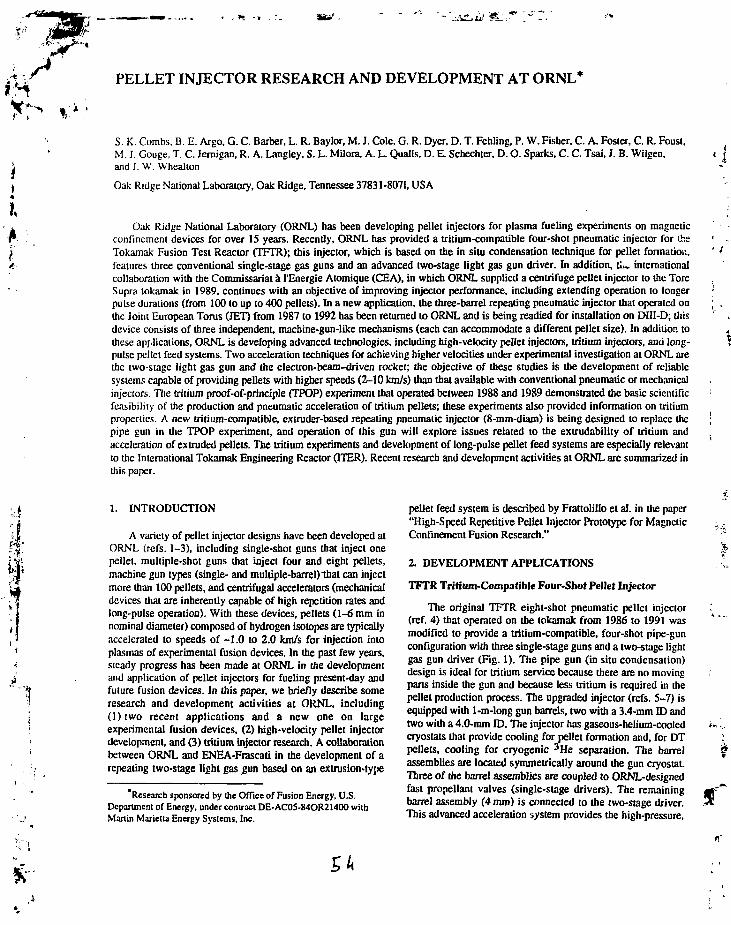
Oak Ridge National Laboratory (ORNL) has been developing pellet injectors for plasma fueling experiments on magneticconfinement devices for over 15 years. Recently, ORNL has provided a tritium-compatible four-shot pneumatic injector for theTokamak Fusion Test Reactor (TFTR); this injector, which is based on the in situ condensation technique for pellet formation,features three conventional single-stage gas guns and an advanced two-stage light gas gun driver. In addition, tli~ internationalcollaboration with the Commissariat a I'Energie Alomique (CEA), in which ORNL supplied a centrifuge pellet injector to the ToreSupra tokamak in 1989, continues with an objective of improving injector performance, including extending operation to longerpulse durations (from 100 to up to 400 pellets). In a new application, the three-barrel repeating pneumatic injector that operated onthe Joint European Torus (JET) from 1987 to 1992 has been returned to ORNL and is being readied for installation on DIII-D; thisdevice consists of three independent, machine-gun-like mechanisms (each can accommodate a different pellet size). In addition tothese applications, ORNL is developing advanced technologies, including high-velocity pellet injectors, tritium injectors, and long-pulse pellet feed systems. Two acceleration techniques for achieving higher velocities under experimental investigation at ORNL arethe two-stage light gas gun and the electron-beam-driven rocket; the objective of these studies is the development of reliablesystems capable of providing pellets with higher speeds (2-10 km/s) than that available with conventional pneumatic or mechanicalinjectors. The tritium proof-of-principle (TPOP) experiment that operated between 1988 and 1989 demonstrated the basic scientificfeasibility of the production and pneumatic acceleration of tritium pellets; these experiments also provided information on tritiumproperties. A new tritium-compatible, extruder-based repeating pneumatic injector (8-mm-diam) is being designed to replace thepipe gun in the TPOP experiment, and operation of this gun will explore issues related to the extrudability of tritium andacceleration of extruded pellets. The tritium experiments and development of long-pulse pellet feed systems are especially relevantto the International Tokamak Engineering Reactor (ITER). Recent research and development activities at ORNL are summarized inthis paper.
1. INTRODUCTION
A variety of pellet injector designs have been developed atORNL (refs. 1-3), including single-shot guns that inject onepellet, multiple-shot guns that inject four and eight pellets,machine gun types (single- and multiple-barrel) that can injectmore than 100 pellets, and centrifugal accelerators (mechanicaldevices that are inherently capable of high repetition rates andlong-pulse operation). With these devices, pellets (1-6 mm innominal diameter) composed of hydrogen isotopes are typicallyaccelerated to speeds of -1.0 to 2.0 km/s for injection intoplasmas of experimental fusion devices. In the past few years,steady progress has been made at ORNL in the developmentand application of pellet injectors for fueling present-day andfuture fusion devices. In this paper, we briefly describe someresearch and development activities at ORNL, including( l ) two recent applications and a new one on largeexperimental fusion devices, (2) high-velocity pellet injectordevelopment, and (3) tritium injector research. A collaborationbetween ORNL and ENEA-Frascaii in the development of arepeating two-stage light gas sun based on an extrusion-type
'Research sponsored by the Office of Fusion Energy, U.S.Department of Energy, under contract DE-AC0S-84OR21400 wilhMartin Marietta Energy Systems, Inc.
pellet feed system is described by Frattoliflo et al. in the paper"High-Speed Repetitive Pellet Injector Prototype for MagneticConfinement Fusion Research."
2. DEVELOPMENT APPLICATIONS
TFTR Tritium-Compatible Four-Shot Pellet Injector
The original TFTR eight-shot pneumatic pellet injector(ref. 4) that operated on the tokamak from 1986 to 1991 wasmodified to provide a tritium-compatible, four-shot pipe-gunconfiguration with three single-stage guns and a two-stage lightgas gun driver (Fig. 1). The pipe gun (in situ condensation)design is ideal for tritium service because there are no movingparts inside the gun and because less tritium is required in thepellet production process. The upgraded injector (refs. 5-7) isequipped with 1-m-long gun barrels, two with a 3.4-mm ID andtwo wilh a 4.0-mm ID. The injector has gaseous-helium-cooledcryostats that provide cooling for pellet formation and, for DTpellets, cooling for cryogenic 3He separation. The barrelassemblies are located symmetrically around the gun cryostat.Three of the barrel assemblies are coupled to ORNL-designedfast propellant valves (single-stage drivers). The remainingbarrel assembly (4 mm) is connected to the two-stage driver.This advanced acceleration system provides the high-pressure.

*"'
./*
tf
\i4
I
LHt CONTROL VALVES
GUARD— SECONDARY VACUUM' CONTAINMENT C H A M B E R ^ h> ^ & V BARREL ISOLATION\ (PHASE nj \ 1,1 i : /v VALVES (4)
.., x l \ klil r»»s""«™« 'S.MGLE.STAGEGUN : ^ V~*J" 'PROPELLAMTVALVEO)-. i \ ! I I / / / (4) : j
r 2-STAGE GUN \ , \ J ! 1/ / / ^ j j _y PROPELLANT VALVE
CRYOSTATSSECONDARYCONTAINMENT(PHASE II)
Fig. 1. TFTR tritium-compatible four-shot pellet injector.
high-temperature driver gas required to accelerate pellets to the2.5- to 3-km/s range. It is based on development of two-stagelight gas guns at ORNL (refs. 8, 9) and in Europe (refs. 10,11).In the two-stage driver, moderate-pressure (20- to 60-bar)helium propeHant gas initially in a 0.64-L first-stage reservoiraccelerates a 25.4-mm-OD Vespel® or titanium piston(25-50 g) in a 0.9-m-long, thick-walled 4130 carbon steelpump tube. The reservoir is connected to the pump tube by aI.9-cm-diam orifice, pneumatically actuated fast valve. Thepump tube is visible in Fig. 1, which also shows the guardvacuum chamber interface. A bellows isolates the twO'Siagedriver and the guard vacuum chamber. The high-pressure endof the pump tube is enclosed in a 4340 carbon steel headassembly. The accelerating piston compresses low-pressure(initially 1 - to 2-bar) room-temperature hydrogen propellantgas that becomes the driving gas for the cryogenic pellet.
In testing at ORNL with deuterium, the single-stage gunsoperated reliably at pellet speeds of up to 1.5-1.7 km/s, and thetwo-stage gun was qualified with intact pellets at speeds of upto 2.8 km/s. The size of individual pellets can be varied usingtechniques demonstrated in the TPOP experiment to freezedifferent amounts of hydrogen ice. The nominal pellet aspectratio (length/diameter) is 1.25, but pellets can be formed withaspect ratios in the range 1.0 to £1.5. The injector was recentlyinstalled on TFTR (Fig. 2) and used in some limited plasma-fueling experiments, including the injection of 4-mm deuteriumpellets at 2.2 km/s with the two-stage gun. This high-speed gunwas designed for optimal performance with tritium, and speedsof up to 3 km/s or greater have been projected with the heavierand stronger material. However, phase II of the originalexperimental plan has been deferred; it called for the injector lobe retrofitted with a D-T fuel manifold and secondary tritiumcontainment systems and integrated into TFTR tritiumprocessing systems to provide full tritium pellet capability. Thepresent plan includes deuterium injection experiments insupport of TFTR D-T experiments in 1994.
Tore Supra Centrifuge Injector .
The centrifuge injector illustrated in Fig. 3 was developedat ORNL and has been operating on Tore Supra since 1989(ref. 12). With the present configuration, the centrifuge has thecapability of injecting up to 100 pellets into a single plasmadischarge. Up to 10 pellets per second can be injected at speedsfrom 500 to 800 m/s, with sizes ranging from 3 to 10 torr»L perpellet [(2-7) x 1020 atoms per pellet]. The accelerator consistsof a carbon fiber/epoxy filament-wound rotor attached to analuminum hub. The 1.5-m-diam rotor is a centrifugal catenaryand spins continuously at a frequency of 60 to 90 Hz; pelletsare captured by the rotor near the axis, accelerated to theperiphery in a track, and ejected tangent to the rotor at twicethe peripheral speed. The pellets leave the rotor at the sameangular position and enter a guide tube that transports thepellets to the tokamak. A differential pumping system in theinjection line effectively removes any gas generated during thepellet acceleration. Pellets are formed and injected into thecentrifuge with the Zamboni-like pellet fabricator. Deuteriumgas is first frozen onto the periphery of a rotating copper diskcooled with liquid helium. As the deuterium ice builds up onthe disk, it is shaved into a triangular cross section. The processof forming a deuterium ice rim takes approximately 15 min.Once the ice rim is formed, up to 100 pellets can be cut fromthe rim at a rate approaching 10 pellets per second with atriangular punch that forms pellets in the shape of roundedtetrahedrons (similar to a taco). By varying the depth of the cut,pellets of different sizes can be formed. The punching anddelivery of the pellets to the rotor are precisely controlled sothat the pellets arrive at the rotor pickup point as it passes by.
The current experimental program that is under waycombines repetitive pellet fueling with an ergodic divertor andpump limiters lo establish and study long-pulse plasmas inwhich the pellet fuel source is in balance with the activeparticle exhaust. With lower hybrid current drive, pulse lengths

P'
INJECTOR SOX
1000-LH» DEWAR
|J4
HIGHVACUUMTANK
TRmUM PELLET INJECTORPRIMARY VACUUM TANK
Fig. 2. Schematic of the tritium-compatible four-sbot injector installation on TFTR.
CENTBIFUGE AHBOR
ZAMBONI DISKDRIVE SHAFT
CENTRIFUGEDRIVE MOTOR
ZAMBONI DISK
ZAMBONIPELLET ' CAUPER
PUNCH MECHANISM
Oj ICE RIM
Fig. 3. Pellet fabrication device and high-speed rotating arborfor the Tore Supra centrifuge injector.
of up to 2 min might be achieved on Tore Supra. Toaccommodate these extended pulse lengths, Foster eta!,(ref. 12) are developing an upgraded pellet fabricationapparatus (Fig. 4) capable of providing up to 400 pellets in acontinuous pulse. In addition, the new feed system shouldimprove the reliability of delivery of pellets to the plasma. Inthe new arrangement, the existing torque motor punch will bereplaced with a four-axis brushless dc servo system. One axis is
dedicated to cutting the pellets from an ice rim; a separate axisis used for delivering the pellets into the rotor. To increase thenumber of pellets from 100 to 400, the single rim of ice in theoriginal design will be replaced by a stack of four rims. Theplanned fueling experiments will provide an experimental basisthat should be useful for determining refueling scenarios forITER and for future steady-state fusion devices.
A similar system extended lo steady-state pellet fabricationtechnology and designed for a radiation and tritiumenvironment is a candidate for a fueling system for ITER. Acentrifuge fueling system would have the capability of takingthe D-T exhaust directly from the torus cryopumping systems,recondensing and purifying the fuel, and injecting thereconstituted pellets into the plasma, thereby minimizing theoverall plant tritium inventory.
Three-Barrel Repeating Pneumatic Injector for DIT.I-D
The injector shown in Fig. 5 is a three-barrel, machine-gun-like device developed at ORNL and operated reliably onJET (refs. 13-16) from 1987 to 1992; it was used to inject-3000 pellets into JET plasmas for fueling experiments. Threeseparate cryogenic extruders are used; each provides acontinuous stream of frozen hydrogen isotope to its associatedgun section, where individual pellets are repetitively formed,chambered, and accelerated. For the JET application, thedevice was equipped with gun-barrel diameters of 2.7,4.0, and6.0 mm (nominally 9 x 10²⁰, 3 x 10²¹, and 1 x 10² 2 atoms perpellet) and capable of repetitive operation (5, 2.5, and 1 Hz,respectively, for each pellet size) under quasi-steady-stateconditions (>10s). The injector has been returned to ORNLand is being readied for installation on DIII-D. Some of theindividual gun hardware will be changed out to provide optimalpellet sizes; in the present scheme the 6-mm gun will bereplaced by one with a 1.8-mm gun barrel and correspondingmechanisms. Since JET did not use a conventional deliverysystem with guide tubes and differential pumping, the injector

VACUUM ROTARY FEEO-THRUS
I,
ROTARY TO UNEAR SLIDE MECHANISM
PELLET PUSHER
_ ZAMBONI DISK WITHFOUR ICE RINGS
PELLET CUTTER
CENTRIFUGE ROTOR
, • • *
Fig. 4. Feed system upgrade for Tore Supra centrifuge injector.
moiof/«crew-pf«*sdrive unit for
solid deuterium extruder
CryCflenic
1
blocks
turral
L-peUtt chamberingmechanism
Fig. 5. Three-barrel repeating pneumatic pellet injector.
will be equipped with such a system, including the pelletdiagnostics required for measuring pellet parameters. Theproposed installation on DIII-D is shown in Fig. 6.
3. HIGH-SPEED PELLET INJECTOR DEVELOPMENT
Two-Stage Light Gas Gun
Several small (4- and 6-mm-diam projectiles) two-stageguns have been constructed and tested in the laboratory(refs. 8-9, 17), and significant progress has been reported,including (1) pellet velocities approaching 3 km/s withdeuterium pellets and over 5 km/s with plastic pellets and(2) the demonstration of repetitive operation with surrogateplastic pellets at 1 Hz and 3 km/s. A two-stage driver/pipe-gunconfiguration based on this technology was recently installedon TFTR and is described in Sect. 2. A schematic of the ORNLrepetitive two-stage light gas gun and key subsystems is shownin Fig. 7. The device comprises several components (andfeatures) that must interact precisely to accomplish repetitiveoperation. The repetitive device consists of most of thestandard components for two-stage light gas guns; in addition,special components were developed for repetitive operation,including a fast valve, mechanisms for automatic pelletloading, and a pneumatic clamping device for sealing the pumptube/gun barrel interface. Necessary techniques for rapid fillingand evacuation of gases and control of pressure levels werealso developed. The typical piston was «40 mm long (with a45° taper on the front) and weighed 25-30 g; it was constructedof polyimide with 15% graphite filler by weight (supplied asVespel® by E. I. du Pont de Nemours & Co., Inc.). Typically, apiston survived for up to hundreds of shots without excessivewear/damage or significant effects on gun performance.

Fig. 6. Planned installation of three-barrel repeating pneumatic pellet injector on DIII-D.
FROM HiCAS SUPPLY V
(5 bar)
FAST VALVE -PISTON(TAPER ON FRONT)
GUN BARREL(4mmlD)
PELLET(SHEAR OETEflUHESBREAK PRESSURE)
TWO-POSITION SLIDE MECHANISM;PELLETS ARE LOADED BY ANAUTOMATIC LOADING DEVICE(NOT SHOWN) IN POSITION 2
TO VACUUM UNEEQUIPPED WITH
LIGHT BARRIERS.FLASH PHOTOGRAPHY.
TARGET PLATE. ANDLARGE VACUUM VESSEL
(450 U1»)
GAS SUPPLY TANKFOB SECOND STAGE
Fig. 7. Schematic of repetitive two-stage light gas gun.
Small plastic projectiles (4-mm nominal size) and heliumgas have been used in the prototype device to demonstraterepetitive operation (up to 1 Hz) at relatively high pelletvelocities (up to 3 km/s). Experimental data for two 10-pellettest sequences with the device operating at 1 Hz are listed inTable 1. The equipment and experiments have been describedthoroughly elsewhere (ref. 16). The highest experimentalvelocity is twice that available from conventional repeatingsingle-stage pneumatic injectors that accelerate frozen pelletsof hydrogen isotopes. Pellets composed of light hydrogen icecan quite easily be accelerated to 3 km/s (refs. 8-11); however,protective shells (or sabots) may be required to protect therelatively weak ice from high acceleration forces andtemperatures in order to reliably achieve velocities approaching5 km/s. Possible sabot/pellet configurations are being evaluated
at ORNL in room-temperature experiments with a larger two-stage gun equipped with a nominal 6-mm-diam rifled gunbarrel bore.
The pellet test repetition rate of 1 Hz is relevant for fuelingapplications on future large fusion research devices. The nextstep in developing a functional high-speed repetitive hydrogenpellet injector is to combine the acceleration technologydescribed here with the cryogenic extruder technology forsupplying hydrogen ice previously developed at ORNL (see,e.g., ref. 18). The ORNL/Frascati collaboration referenced inSect. 1 is an important part of that development. In thisinternational effort, an ORNL continuous deuterium extruder(equipped with pellet-chambering mechanism and gun barrel)and a small ENEA-Frascaii two-stage gun wilJ be combined todemonstrate and study repetitive operation with bare deuterium
ft

•A
If3
Table 1. Experimental data for two 10-pellet test sequences with repetitive two-stagelight gas pun operating at 1 Hz
Transient timing data3 (s;
1
Pelletnumber
Gun muzzlelight gate
Target plateacceleromeier
Flight time4'(ms)
Pellet velocity(m/s)
Test sequence 1056
First-stage pressure: 62 bar Piston mass: 25 g Pellet material: aceulSecond-stage pressure: 0.8 bar Pellet mass: 0.055 g Pellet shape: solid cylinders
Pellet size: 4.0 mm diam x 3.5 mm long
, • • *
123456789
10
0.0711061.07376592.07403613.0746314.0753365.07582576.0764817.06880578.0777769.070187
First-stage pressure: 100 barSecond-stage pressure: 0.8 bar
123456789
10
0.0718111.07454092.0747813.0753714.07607085.0765616.0772117.0695418.0785119.070921
Test sequence 1109
Piston mass: 30 gPellet mass: 0.029 g
Pellet size: 4.0 mm diam
0.0518461.04763092.04817583.05103094.0489015.0496116.04237137.04975138.0509519.051056
0.0523211.04810092.0486813.05155094.04941135.05011136.0428817.0502218.051489.051620
705775745740735735730735735734
2130193520152030204020402055204020402045
Avg = 2040
Pellet material: polypropylenePellet shape: solid spheres
475470505520510500520470529564
3160319029702885294030002885319028352660
Avg = 2970
"Taken as lime of abrupt change in instrument signals is determined by software code that analyzesraw transient data.
^Separation distance of 1.5 m between muzzle light gate and target plate
ice. For an alternative design, the key elements of the repetitivetwo-stage light gas gun described in this section can also bereadily integrated into a pellet injection system, with or withoutsabol-handling capability.
Electron-Beam-Heated Rocket
While the previous high-velocity technique has beenapplied in other areas of research for many years, a newmethod of accelerating pellets to high velocity using a high-power, magnetically compressed electron beam is underdevelopment by Foster et al. at ORNL (refs. 19-21). With thistechnique, intense electron-beam heating is applied to a solidhydrogen surface to evaporate gas at elevated temperature andthus generate a net propulsive force. In one scheme, hydrogen
ice propellant "sticks" (long pellets) are ablated and used toaccelerate the payloads, which could be deuterium, tritium, orD-T mixtures. Researchers have observed the "rocket effect"on pellets (asymmetric trajectories) injected into tokamakssince the first pellet fueling experiments. The neutral shieldingmodel for pellet ablation in a plasma treats the plasma as anelectron beam, and it has been adapted and employed as thephysics model for the electron-beam-heated rocket.
A proof-of-principle apparatus (Fig. 8) with an effective0.4-m acceleration path has been constructed and operated;cryogenic pellets of both hydrogen and deuterium (4-mm diamand up to 12-mm long, formed in a pipe gun) have beenaccelerated, with speeds of up to 580 m/s recorded with intacthydrogen pellets (using an electron beam of 10 kV, 0.8 A, and1 ms). For some selected data, the measured velocities as a f

rr m"4
f1
, - • *
ROGOWSKl COILS
Fig. 8. Schematic of electron-beam rocket pellet accelerator, consisting of a pipe-gun-type pellet source, an electron gun, a pelletaccelerator with guide rails and electromagnets, and diagnostics.
function of electron-beam current are compared with a theory 600adapted from the neutral gas shielding model (ref. 19) in Fig. 9.In the scan of beam current, the beam voltage increasessystematically from 4.5 kV to 14 kV as the current increases.Good agreement with the theory is obtained if it is assumedthat two-thirds of the beam power is absorbed in the expandinggas and one-third of the exhaust gas velocity contributes todirectional acceleration of the pellet. In the presentexperiments, the limits of the acceleration for hydrogenic 4 0 0
pellets are found to correspond to an effective accelerationpressure of 0.2 MPa. To overcome this limitation, a higher-strength material such as lithium or lithium hydride has been S"proposed as the propellant material. A parametric analysis of -S-systems capable of accelerating pellets to lOkm/s has been ^made. The accelerator characteristics are shown as a functionof beam voltage in Fig. 10 for a constant perveance (I/V^/2) of12 pP. The symbols £n. Po> and S correspond to initial pelletlength, acceleration pressure, and accelerator length,respectively. Two design points are indicated (DPI, DP2)corresponding to acceleration lengths of 2 m and 12 m andbeam currents of 100 A and 38 A, respectively. The differencerepresents a trade-off between accelerator length andacceleration pressure. Some initial tests with lithium andlithium hydride pellets are under way.
04. TRITIUM INJECTOR RESEARCH
The TPOP experiment was operated in the period 1988- Fig. 9.1989 to demonstrate the basic scientific feasibility ofproduction and pneumatic acceleration of tritium pellets forfueling future fusion reactors (refs. 22-23). The experimentwas designed and built at ORNL and installed and operated by
200
-RANGE OFTHEORY
(SHOTS 1823-1854)
0.2
I (A)
0.4
Proof-of-principle electron-beam rocket acceleratorperformance.
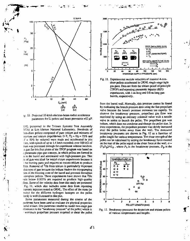
f t
"I
in. 10. Projecied 10-km/s electron-beam rocket acceleratorparameters for Li pellets and beam perveance =12 jiP.
XXL personnel in the Tritium Systems Test AssemblySTA) at Los Alamos National Laboratory. Hundreds of:nm-diam pellets composed of pure tritium and mixtures ofmerium and tritium (equilibrium D-T; T2 = D2 = 25% andT = 50% by volume) were made and accelerated in thisvice, with speeds of up to 1.4 km/s recorded; over 100 kCi of:ium was processed through the experiment without incident.ic gun for this first phase of the TPOP program was based on.- pneumatic pipe-gun concept, in which pellets are formed in11 in the barrel and accelerated with high-pressure gas. This•x of gun was ideal for initial tritium experiments because its no moving pans and requires no excess tritium to produceIlets. Removal of 3He from tritium is particularly importantthis type of gun because the helium hinders the cryopumpingdon in the freezing zone of the barrel and prevents formationcomplete pellets. These experiments have shown that 3He
vels below 0.005% are required 10 produce high-qualityIlets. Some of the velocity data from this study are presentedFig. 11, which also includes some data from repeating
eumaiic injectors tested at ORNL. The effect of the mass (ornsiiy) for the different hydrogen isotopes on the pelletlocity is well illustrated in this plot.
Some parameters measured during the course of thepcrimem have been used to evaluate the physical propertiessolid tritium. One parameter needed to model two-stage gunrformance is the "breakaway pressure" of the pellet,'which is.- minimum propellant pressure required to shear the pellet
200c
8.
-1—1—1—1—1—1—1 1—1—1—1 1 1 i"
*» .*«.
TPOP PATA (PIPE GUN)O H 2
• Dj4 DT <5O/5O MIXTURE)
T
RPI DATA (REPETITIVE GUM)— H2
7~ i I I I I ( I 1_40 60 80 100 120 140
HYDROGEN SUPPLY PRESSURE (bar)160
Fig. 11. Experimental muzzle velocities of nominal 4-mm-diam pellets accelerated in ORNL single-stage lightgas guns. Data are from the tritium proof-of-principle(TPOP) and repeating pneumatic injector (RPI)experiments, with 1-m-long and 0.8-m-long gunbarrels, respectively.
from the barrel wall. Normally, this pressure cannot be foundby evaluating the breech pressure data using the fast propellantvalve because the breech pressure increases 100 rapidly. Toobserve the breakaway pressure, propellant gas flow wasrestricted by using an ordinary solenoid valve with a needlevalve in series to launch the pellet. The propellant gas washelium, which does not condense and change the pellet size. Inthese experiments, the propellant pressure was slowly increaseduntil the pellet broke away from the wall. The measuredbreakaway pressures are shown in Fig. 12 as a function ofpellet length for various temperatures. The shear strength of thepellet can be calculated by setting the breakaway force exertedon the rear of the pellet equal to the shear force at the wall, a =
. where P\, is the breakaway pressure, Z3p is the
60
•=-502uT§ 40'&F30
20 -
1
-
1 1
TEMPERATURE (K)O2
0 6a sA 10
T2
B 8• 9
I i
I
c
•
A S?
r i i
*
-
• 0
1 1 1
10 -
0 1 2 3 4 5 6 7 8
PELLET LENGTH (mm)
Fig. 12. Breakaway pressures for deuterium and tritium pelletsof various temperatures and lengths.
6\

X
i
I,
.•llet diameter, and Lp is the pellet length. Values of the shearrength inferred in this way are presented as a function ofmperature in Fig. 13. Also shown are the ultimate tensilerengths of hydrogen (ref. 24) and deuterium (ref. 25). Strictlycaking, the shear strength and tensile strength of a materialc not necessarily equal. However, the shear strength andnsile strength of deuterium have similar magnitudes andmperature dependencies. The shear strength for tritium is->out twice that of deuterium at 8 K. This may seem like arge difference between isotopes; however, the tensilerengths of hydrogen and deuterium show similar large:ffcrences. Tritium pellets should be able to withstand higher.cclerations (or pressures) than hydrogen or deuterium pelletsiihout fracturing because of the greater strength. In principle,lis makes tritium ice an attractive candidate for advanced;celeration techniques, such as the two-stage light gas gun.
A new 8-mm (ITER-relevant), tritium-compatible,•ctruder-based repeating pneumatic injector is being designedj replace the pipe gun in the TPOP experiment. Operation ofus gun will explore issues related to the extrudability ofilium and acceleration of extruded pellets. Tritiumxperiments with this gun are expected to begin at TSTA in794.
. SUMMARY
In this paper, we have summarized the recent progress andatus of pellet injection research and development activities atJRNL, including applications of recent injection systems onresent large experimental fusion devices. With ITER
14
12
10
: 8
j
i 6
4
2
n
1 '
-
-
-
-
-
08
AA
8
^ * — < —o
1 1 1 1 1 1 1 1
A
CALCULATEDSHEAR STRENGTHS
FROM EXPERIMENTALBREAKAWAY DATA
OD2 4 T 2
ULTIMATE TENSILESTRENGTHS REPORTED
IN LITERATURE
X H 2 +t}2
-
-
-
-
e
8 10 12TEMPERATURE (K)
14 16
i£. 13. Shear strengths of deuterium and tritium ice estimatedfrom breakaway pressure data. Lines representreported ultimate tensile strengths of hydrogen anddeuterium.
becoming an important pan of the fusion program in the UnitedStates and worldwide, a large part of future ORNLdevelopment will be directed in support of the largeinternational fusion device. The present high-velocity pelletinjector development and tritium research are particularlyrelevant to ITER and future experimental fusion devices orreactors. Also, applications such as ITER will require long-pulse fueling, and reliable steady-state operation of pelletinjection systems is a major objective of the ORNL program. Astraightforward technique in which multiple extruder units ofidentical design operate in tandem to provide a continuoussource of hydrogen ice for steady-state operation may be asolution; this approach makes use' of a reliable ORNLtechnology. Also it is possible that the capability of theZamboni-type feed system used on the Tore Supra centrifugeinjector can be extended to steady-state pellet fabricationtechnology. Development of these techniques is planned, andsuch feed systems, combined with reliable accelerationsystems, can form the basis for a steady-state pellet fuelingsystem for ITER and fusion reactors.
ITER and future fusion reactors will require a flexibleplasma fueling capability with a mix of gas puffing, low- andhigh-velocity DT pellets to satisfy the multiple physics andengineering constraints of fusion power density, bum control,tritium bum fraction, edge density for plasma mode (L, IT)control, and gaseous divertor density for efficient plasmaexhaust and protection of plasma-facing components. Pelletfueling offers a unique capability for influencing theperformance of ITER core plasmas: large, high-speed pelletsinjected in the bum phase may provide sufficient control of thedensity profile to allow operation in a region of enhancedthermal reactivity, and high-speed pellets injected in the startupphase could provide improved ignition margins. Deeper fuelingcapability allows isotopic tailoring of the various fuelingsources and more control of the tritium bum fraction and globaltritium inventory.
REFERENCES
1. S. L. Milora, J. Fusion Energy 1,15 (1981).
2. S. L. Milora, / . Vac. Sci. Technol. A 7(3), 925 (1989).
3. S. K. Combs, "Pellet Injection Technology," in press, Rev.Sci. Instrum. (August 1993).
4. S. K. Combs et al.. Rev. Sci. Instrum. 58,1195 (1987).
5. S. L. Milora et al., "Design of a Tritium Pellet Injector forTFTR," Proc. 14th Symp. on Fusion Engineering (IEEE,New York, 1992), vol. 2, p. 716.
6. M. J. Gouge et al., Fusion Technology 21 (no. 3, pt. 2A),1665 (1992).
7. G. W. Barnes et al.. Fusion Technology 21 (no. 3, pt. 2A),1662 (1992).
8. S. K. Combs et al., / . Vac. Sci. Technol. A 7,963 (1989).
9. S. K. Combs et al., / . Vac. Sci. Technol. A 8(3), 1814(1990).
10. F. Scaramuzzi et al., Proc. 16th Symp. on Fusion Tech. 1,747 (1991).
f
I
P. Kupschus et al., Proc. 16ih Symp. on Fusion Tech. 1,268 (1991).
. C. A. Foster et al., "ORNL Centrifuge Pellet FuelingSystem," presented at the 17th Symposium on FusionTechnology, Rome, September 14-18, 1992 (proceedingsto be published).
. S. L. Milora et al., in Proc. 12th Symp. on FusionEngineering, Monterey, 1987 (IEEE, New York, 1987),pp. 784-86.
. P. Kupschus ct al., in Proc. 12th Symp. on FusionEngineering. Monterey, 1987 (IEEE, New York, 1987),pp. 780-83.
S. K. Combs ct al. . / . Vac. Sci. Technol. A 6,1901 (1988).
S. K. Combs et al.. Rev. Sci. Instrum. 60(8), 2697 (1989).
S. K. Combs et al., Rev. Sci. Instrum. 62(8), 1978 (1991).
S. K. Combs et al.. Rev. Sci. Instrum. 56(6), 1173 ( 1985).
C. A. Foster et a)., in Proc. IAEA Technical Meeting onPellet Injection and Toroidal Confinement, Gut Ising,1988, IAEA-TECDOC-534 (International Atomic EnergyAgency, 1989), p. 275.
20. C. C. Tsai et al., in Proc. 14th Symp. on FusionEngineering, San Diego, 1991 (IEEE, New York, 1992),vol. 2, p. 724.
21. C. C. Tsai et al., "Electron-Beam Rocket Acceleration ofHydrogen Pellets," J. Vac. Sci. Technol. A. accepted forpublication.
22. P. W. Fisher, Tritium Proof-of-Principle Pellet Injector,ORNL/TM-11781, Martin Marietta Energy Systems, Inc.,Oak Ridge Nail. Lab., July 1991 (available from theNational Technical Information Service, Springfield, VA22161).
23. P. W. Fisher, Fusion Technol. 21.794 (1992).
24. L. A. Aleksecva, O. V. Litvin, and I. N. Krupskii, Sov. J.Low Temp. Phys. 8,158 (1982).
25. D. N. Bolshutkin, Y. E. Stetsenko, and L. A. Alekseeva,Sov. Phys. Solid State 12,119 (1970).

r1 J
HIGH-SPEED REPETITIVE PELLET INJECTOR PROTOTYPE FORMAGNETIC CONFINEMENT FUSION RESEARCH
A. FRATTOLILLOl, M. GASPAROTTOi, S.MIGLIORIi, F. SCARAMUZZI2, G.ANGELONEi,M. BALDARELLU, M. CAPOBIANCffli, C. DOMMAi, G. RONCP, S. K. COMBS3, S. L. MIL0RA3,C. R. FOUST3, M. J. GOUGE3, R. CARLEVARO*. G. B. DAMINELLI*. A. REGGIORI4, G. RIVA4
i Associazione EURATOM-ENEA sulla Fusione, Centro Ricerche Energia Frascati, C.P. 65 - 00044Frascati, Rome, Italy.
2ENEA, Area INN, Dipartimento Sviluppo Tecnologie di Punta, Centro Ricerche Energia Frascati,C.P. 65 - 00044 Frascati, Rome, Italy.
3Oak Ridge National Laboratory*, P. O. Box 2009, Oak Ridge, Tennessee 37831 - 8071, U.S.A.
*CNPM - CNR Viale F. Baracca 69, 20068 Peschiera B. (MI), Italy
The fuelling requirements of future magnetic confinement devices for controlled thermonuclearresearch (e.g. ITER) indicate a need to upgrade the performance (speed, mass, number of pellets, etc.)of present-day pellet injectors. An experiment in collaboration between ENEA Frascati and ORNL hasbeen started, with the objective of demonstrating a repeating pellet injector capable of delivering D2ice pellets at rates around 1 Hz and with speeds in the range 1 -=-3 km/s, using an existing ORNLextruder and a Frascati two-stage gun. This activity will be carried out in the framework of acollaborative agreement between U.S. D.O.E. and EURATOM - ENEA Association. The result ofnumerical simulations and preliminary tests of the two devices, which will be matched together inOak Ridge, are described. The results of a study in course at CNPM-CNR (under ENEA contract)about the possibility of minimizing the piston .wear, are also reported.
IINTRODUCTION
Pellet injection requirements of Next Stepmagnetic confinement fusion devices (e.g. ITER)are anticipated to be different in the start-up andthe burn phases [1,2] A transient peaking of thedensity profile may be desirable during the start-up, in order to improve global confinement [3](PEP mode) and achieve enhanced fusion powerproduction, thus reducing the external powerneeded to reach burn conditions; a limitednumber of pellets injected at a speed in the range3- -5 km/s could be necessary for this purpose.During the burn phase, on the other hand, acontinuous shallow fuelling could be foreseen, inorder to provide independent control of edge andcore plasma densities and to achieve a flat profile,thus resulting in improved MHD stability andminimising the central peaking of impurities andof He ashes; this indicates a need of developing acw pellet injector, capable of delivering pellets ofmoderate size at about 1 Hz rate and with speedsin the range 1*3 km/s.
Currently, the most suitable method ofcontinuously producing a considerable number ofhydrogen pellets at the desired rate is theextrusion/chambering technique developed byORNL [4,5]. In this cryogenic process, hydrogenor deuterium gas is frozen and force fed to theacceleration stage. With repetitive single-stagelight gas guns and the hydrogen extrudertechnique, reliable operation at quasi-steady-state or long-pulse (>10 s) conditions have beenachieved, including pellet rates of 1 to 5 Hz andspeeds of 1.0 to 1.5 km/s (with pellet sizes in therange 2- to 6- mm diam). The two-stage light gasgun (TSG), which has been successfully used atENEA-Frascati to accelerate solid deuteriumpellets up to velocities of 3.3 km/s [6], is the mostreliable technology for launching cryogenicpellets at very high speeds. Thus a collaborationbetween the ORNL and Frascati teams has beeninitiated in which a Frascati TSG will becombined with an existing ORNL extruder. Theobjective of this work is to demonstrate thefeasibility of a repetitive high-speed pelletinjector based on these technologies [7]. The key
6h
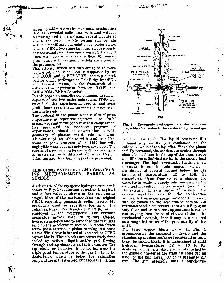
PS-
issues to address are the maximum accelerationthat an extruded pellet can withstand withoutfracturing and the maximum repetition rate atwhich the extruder/TSG system can operatewithout significant degradation in performance.A small ORNL two-stage light gas gun previouslydemonstrated repetitive operation at 1 Hz and 3km/s with plastic surrogate pellets [8], similarparameters with cryogenic pellets are a goal ofthe present effort.This activity, which will turn out to be relevantfor the burn phase of ITER, is supported by theU.S. D.O.E. and by EURATOM; the experimentwill be jointly performed in Oak Ridge by ORNLand Frascati teams, in the framework of acollaborative agreement between D.O.E. andEURATOM - ENEA Association.In this paper we describe the engineering-relatedaspects of the two major subsystems (TSG andextruder), the experimental results, and somepreliminary results from numerical simulation ofthe whole system.The problem of the piston wear is also of greatimportance in repetitive injectors. The CNPMgroup, working in the context of this co-operation,has performed an extensive program ofexperiments, aimed at determining possiblegeometry of pistons, which minimize wear.Aluminum pistons able to withstand over 1000shots at peak pressure of = 1550 bar withnegligible wear have already been developed. Theresults of new tests performed with pistons madeof materials with different densities (Nylon,Titanium and Beryllium-Copper) are presented.
THE ORNL EXTRUDER AND CHAMBER-ING MECHANISM/GUN BARREL AS-SEMBLY
A schematic of the cryogenic hydrogen extruder isshown in Fig. 1 (deuterium operation is depictedand a fast valve is shown as the accelerationstage). Most of the hardware from the originalORNL repeating pneumatic pellet injector [4],previously used for repetitive fueling on theTokamak Fusion Test Reactor (TFTR) [5], will beemployed in the experiments. The extruderapparatus serves both to solidify (freeze)hydrogen isotopes and to force feed the resultingsolid to the acceleration section. A motor-drivenscrew press actuates a piston running in a brasssleeve. The sleeve is brazed at both ends to OFHCcopper blocks. These blocks are convectively forcecooled by helium (liquid and/or gas) flowingthrough cooling channels on their exteriors. Thetop block, or liquefier, is controlled near thetriple-point temperature of the gas (~ 19 K fordeuterium), which is below the saturationtemperature of the gas feed but above the melting
PISTON SHAFT
Fig. 1 Cryogenic hydrogen extruder and gunassembly (fast valve to be replaced by two-stagegun
point of the solid. The liquid reservoir fillsautomatically as the gas condenses on thesubcooled walls of the liquefier. When the pistonis fully retracted, the condensate drains throughchannels machined in the top of the brass sleeveand fills the cylindrical cavity in the second heatexchanger. The liquid eventually (within a fewminutes) freezes in this region, which ismaintained at several degrees below the gastriple-point temperature (12 to 16K fordeuterium). Upon freezing of a charge, theextruder is ready to supply solid material to theacceleration section. The piston speed (and, thus,the extrusion time) is controlled to match thedesired repetition rate for the accelerationsection. A transition nozzle provides the propersize ice ribbon to the acceleration section. Anextrusion of solid deuterium is shown in Fig. 2; itsvery clean and transparent appearance is ratherencouraging from the point of view of the pelletmechanical strength, since it may be consideredas a rough indication of the good quality of thissolid.The third copper block shown in Fig. 1accommodates the acceleration device and thechambering mechanism/barrel combination unit.Like the second block, it is maintained at solidhydrogen temperatures (12 to 16 K fordeuterium). The pellet diameter is established bythe inside diameter of the stainless steel tubingused for the gun barrel, which is presently 2.7mm. The gun assembly uses a punch-type

ss.
Fig. 2 Solid deuterium extrusion as viewedbelow gun mechanism
chambering mechanism in which the stainlesssteel gun barrel is brazed directly to a solenoidplunger. When the solenoid is activated, theknife-edge end of the barrel is driven into theextrusion, punching out and chambering a pellet.While the punch mechanism is engaged, thehydrogen propellant is admitted to the gun breechvia the acceleration device. An alternativechambering technique was employed on thethree-barrel repeating pneumatic pellet injectorused for plasma fueling experiments on the JointEuropean Torus [9,10]; for that application aseparate tube on the breech side of the gunpunched out and chambered the pellets. After
,5 initial experiments, conversion to the new design| can be carried out if deemed advantageous. The
;-|. present barrel punch arrangement is shown in->• Fig. 1. The extruder will be capable of providinghi; about 60 to 80 pellets for a single freezing charge.' I ' The pellet size can be changed with somelA mechanical modifications. For this study, the fastk
j valve shown in Fig. 1 will be replaced by theFrascati two-stage gun.
/ The system described above has been setup in the, laboratory at ORNL, including modifications to' accommodate the Frascati two-stage gun. With'• the present configuration, the propellant valvef and two-stage apparatus are interchangeable
'} with minimal effort. With the propellant valve) installed, the system has been tested at 1 Hz andj . —1.0 km/s with deuterium pellets; thus, the! l cryogenic components (extruder and pellet
chambering mechanism/barrel combination),diagnostics and data acquisition, and other ORNL
: subsystems have been thoroughly checked outand qualified.
Numerical simulation results
Preliminary numerical simulations of pelleti acceleration by a two-stage light-gas gun were
performed, in order to properly choose the designparameter of the Repeating Two-Stage Gun(RTSG), taking into account the geometricalcharacteristics of the ORNL extruder (2.7 mm i.d.,-80 cm long barrel). Both QU1CKGUN [11] andthe code developed by CNPM - CNR [12,13) wereused for this analysis. Table I summarizes theresult of some calculations performed using theactual parameters of the Frascati RTSG (eft-Table II), allowing the distance L from the end ofthe pump tube to the pellet initial location, andthe pellet release pressure to vary, while thefilling pressures in the two stages of the gun areessentially kept constant.On the basis of these calculations it is possible tomake some important observations:i: the distance L does not effect theperformance of the injector significantly; asexpected, increasing L results in decreasingperformance, however the difference in the pelletvelocity is about 100 m/s (~3%) when L goes from10 to 25 cm.ii: the effect of the pellet release pressureseems to be a little bit more significant, as can beeasily seen comparing rows 6 and 7 in Table I;reducing this parameter by about a factor 2results in a loss of about 10% in pellet speed.iii: in all but the last two cases, pellet velocitiesin the range 2.9-5-3.4 km/s can be achieved with apeak pressure around 70 MPa, and with amaximum acceleration on the pellet of the orderof 107 m/s2, which is commonly considered inliterature [14] as a safe condition from the point ofview of the pellet integrity; for instance, in thecase of the 3.3 km/s Frascati injector, thecalculated average pellet acceleration [15] is= 1.36-107 m/s2.
The ENEA Frascati repeating two-stage gun
Figure 3 is a picture of the Frascati RTSG, whosefinal design parameters are summarized in TableII. This device is equipped with a set ofdiagnostics (fig. 4), consisting of a couple ofpiezoelectric pressure transducers located at thetwo extremities of the pump tube, anaccelerometer sensing the shock produced by theopening of the 1st stage fast valve, and a light-gate arrangement to detect the presence of thepiston in its back position. These diagnostics, inaddition to providing performance evaluation,allow a precise measurement of characteristictimes of the RTSG; these experimental data mayalso be used to better estimate some of the inputparameters of numerical codes, thus improvingthe simulation accuracy.The RTSG has been extensively tested inFrascati, Bhowing reliable and reproducibleperformance, well beyond expectation, since it

Table I -Modelling of ORNL - ENEA repeating two-stage pellet injector
Barrel length
Barrel diameter
pellet length
pellet mass (D2)
Propellant gas
L
(cm)
10
15
20
25
25
25
25
25
15
1st stagepressure
(MPa)
2.5
2.5
2.5
2.5
2.5
2.5
2.5
2.5
2.5
2nd stagepressure
(MPa)
0.14
0.14
0.14
0.14
0.16
0.15
0.15
0.13
0.13
Pelletrelease
pressure(MPa)
3.0
3.0
3.0
3.0
3.0
3.0
1.6
1.6
1.6
Pelletvelocity
(m/s)
3418
3380
3338
3300
2976
3131
2874
3246
3332
80 cm
2.7 mm
2.7 mm
3.0 mg
H2/H2
Max. pelletbase
pressure(MPa)
6.5
7.4
8.2
9.1
5.1
6.7
5.7
11.4
9.1
Max. pelletacceleration
(107m/s2)
1.20
1.37
1.51
1.69
0.94
1.24
1.06
2.11
1.69
Pressurepulse
amplitude(MPa)
70.1
72.7
75.4
78.0
57.7
66.6
66.6
92.8
87.6
Table II - Main parameters of the-FrascatiRTSG
reservoir volume (cm3)
pump tube i.d. (cm)
pump tube length (cm)
piston material
piston mass (g)
piston length (mm)
piston nominal diameter (cm)
315
2.505
35
ergal
13
14
2.498
was essentially conceived as a prototype aimed atgiving a proof of principle, without pretension ofvery high reliability as required in the case of aninjector operating on a tokamak. Operatingsequences of the gun are controlled by means of
f
Fig. 3 The Krascati RTSG

A
Shockaccelerometer
Piezoelectricpressuretransducer
Fast To vacuum Light gatevalve pump
Fig. 4 Schematics of the Prascati RTSG and diagnostics location
Piezoelectricballistictransducer
m-
an Allen - Bredley SLC500 Programmable LogicController (PLC). A description of the controlsystem has been given elsewhere [7], so it notdiscussed here; however, a very good timingprecision (with a jitter contained within 1 ms) wasachieved by . optimizing the behaviour ofmechanical components and making optimum useof some utilities of the PLC, whose time jitter, ina standard condition, is of the order of ± 5 ms.More than 8000 shots have been performed usinghydrogen gas; the repetition rate may be changed"on line" (i.e. while the RTSG is running) fromsingle-shot operation up to 1 Hz, by simplymodifying the content of a hold register in thePLC. It is also possible to vary "on line" theamplitude of the pressure pulse within the range8-5-70 MPa, by changing the set-point of theinitial filling pressure of the pump tube (from 350down to 80 kPa) while the reservoir pressure iskept at about 2.3 MPa; this range of the peakpressure should more or less correspond,according to our experience and to the results ofnumerical simulations, to pellet velocities in thetarget range 1-4-3 km/s.Up to about 1600 consecutive shots at 1 Hz ratewere performed, with pressure pulses of about 70MPa, without observing dramatic degradation inperformance. Toward the end of this experimentalrun, the amplitude of the pressure pulsesproduced by the RTSG was on the average about10% lower than at the beginning; by the way itwas possible to recover the initial performance byslightly changing "on line" the pump tube fillingpressure. The piston (whose initial diameter was2.498 cm) was then extracted from the pump tubein order to check its condition. It turned out to beslightly conically shaped, with a decreasingdiameter from the rear (2.485 cm) to the front
(2.475 cm), and with a rather scratched lateralsurface. There was also evidence of = 2 0 ^ ovalingin the initially cylindrical shape.Some runs of a few hundred shots with 1 Hz rateand pressure pulses of up to 150 MPa were alsocarried out, showing an increased piston wear,which may be mostly due to the considerableheating produced in these conditions. Operationunder these severe conditions is not plannedwithin the context of the RTSG experimental testprogram
PISTON WEARCNPM-CNR
INVESTIGATION AT
The effects of the piston wear in two-stage lightgas gun injectors have been studied at CNPM inthe aim of obtaining more than 1000 shots with aminimum wear. A piston capable of suchperformances was already developed and testedwith the gun installed at CNPM (length of thepump tube 2 m, diameter 35 mm) [7]; this pistonwas made of aluminum with a mass of 86 g. Thatgeometrical configuration is practically usableonly with light materials as aluminum or nylon.However, in order to withstand high pressuresand temperatures, more resistant materialsshould be employed: so far, the best results havebeen obtained with piston made of Cu-Be. Withthese pistons good performances have beenreached but the mass involved was too large(~260g). In order to keep the piston mass wellbelow these values, a shorter piston with smalllength/diameter (LA}> = 15/35) ratio has beenadopted Fig. (5a). However tests with thisconfiguration gave unsatisfactory results,possibly because during its stroke the piston wasnot well balanced: that caused strong

r m.
A
1
— 15 — a) b)
-*34.97
JBeril bronzm: 60 g
Nylonm: 30g
Fig. 5 PistoD configuration used for wear testsat CNPM • CNR
wear and poor compression. In order to improvethe behaviour of the piston during its stroke asecond piston made of nylon has been added onthe back Fig. (5b). With such configuration, testsin air have been carried out. A continuoussequence of 1000 shots was carried out, with thefollowing test conditions:
Test gas: airMass of piston a: 60 gMass of piston b: 30 gRepetition rate: 0.1 HzMaximum pressure: 1000 barMaximum piston velocity: ~ 400 m/s
At the end, low wear (~10 um in diameter forpiston a and ~70 um on the front of piston b) wasfound, with no significant changes in the pistonperformances. A similar experiment has beencarried out in H2 for —100 shots, still with goodperformances, but a larger wear of the pistons, inparticular in the forward part of the nylon pistonwas observed (—10 um for piston a and ~100 umon the front of piston b): this may be due to theleakage of H2 around the first piston. Furthertests are on the way by utilizing the same kind ofCu-Be piston but employing differentconfigurations and materials (Teflon, Aluminum)for the second piston
CONCLUSION
The requirement of a cw or long pulse injector,capable of delivering pellets at rates around 1 Hzwith speeds in the range 1+3 km/s, is foreseen forthe burn-phase of ITER.An experimental effort has been started, in thecontext of a co-operative agreement between U.S.DOE and EURATOM, in order to demonstrate thefeasibility of such a pellet injector, using anORNL extruder and a Frascati RTSG.The two subsystems have been thoroughlychecked and qualified, showing very goodperformance; the experiment will be jointly
performed at the ORNL by the two parties. Thefirst preliminary results should be availablewithin next Summer.The problem of piston wear in a RTSG is underinvestigation at CNPM/CNR under ENEAcontract.
REFERENCES and FOOTNOTE* Managed by the Office of Fusion Energy,U.S. Department of Energy, under contract DE-AC05-84OR21400 with Martin Marietta EnergySystems, Inc.[1]- Report of the Ad-Hoc Group on PelletInjector Development, EUR.FU 92/PC/33/5a[2] - F. Engelmann, P. Dinner - "Physics Aimsand Technological Requirements of PelletInjectors for the Next Step" - Presented at theWorkshop on Pellet Injectors, ENEA Frascati,Italy, Sept. 21-22,1992[3] - M. Kaufmann et al. - Nucl. Fusion, 28, May1988, pp 827 - 848
[4] - S. K. Combs et al. Rev. Sci. Instr. 56(6),June 1985, pp. 1173-1178[5] - S. K. Combs et al. J. Vac. Sci. Technol.A4(3), May/Jun 1986, pp. 1113 -1117[6] - A. Frattolilloetal. "3.3 km/s solid D2 SinglePellet Injector for the Frascati TokamakUpgrade" - Proc. of the 14th IEEE Symposium onFusion Engineering, San Diego, CA, U.S.A., Sept.30 - Oct. 3,1991[7] - A.Frattolilloetal.-"High-SpeedRepetitivePellet Injector Prototype for MagneticConfinement Fusion Devices", Proc. of the 17thSOFT, Rome, Italy, Sept. 14 - 18, 1992, to bepublished[8] - S. K. Combs et al. Rev. Sci. Instr. 62(8), pp.1978 -1989, Aug. 1991[9] - S.K. Combs, et al. J, Vac. Sci. Techn. A6(1988) 1901[10] S.L. Milora, et al., in: IEEE 14thSymposium on Fusion Engineering, San Diego,CA, U.S.A., Sept.30/Oct.3,1991, IEEE, New York1991, p. 784[11] S. L. Milora, S. K. Combs, M. J. Gouge -"QUICKGUN: An Algorithm for estimating theperformance of Two Stage Light Gas Guns"-ORNIVTM-1156, Oak Ridge Nat. Lab. (1990)[12] - G. Riva and A. Reggiori - Fusion Techn., 15,pp. 143-153, Mar. 1989[13] - G. Riva and A. Reggiori - Fusion Techn.,21, pp. 31-40, Jan. 1992[14] S.L. Milora - J. Vac. Sci. Techn. A7(3),May/June 1989, pp 925-937[15] A. Frattolillo et al. Proceedings of theWorkshop on "Diagnostics for ContemporaryFusion Experiments", Editrice Compositori - SIF,1991, pp. 999-1016

r J
INJECTION OF SOLID D2 PELLETS INTO THE FRASCATITOKAMAK UPGRADE
F.ALLADIOi, P.BURATTIi, A. FRATTOLILLOl, M.GROLLIi, P.MICOZZIi, S.MIGLIORIi,F. SCARAMUZZP, J.A. SNIPES3, G. TONINIl, M. ZERBINIl
i Associazione EURATOM-ENEA sulla Fusione, Centro Ricercbe Energia Frascati, C.P. 65 - 00044Frascati, Rome, Italy.
2ENEA, Area INN, Dipartimento Sviluppo Tecnologie di Punta, Centro Ricerche Energia Frascati,C.P. 65 - 00044 Frascati, Rome, Italy.3MIT Plasma Center, Cambridge MA, U.S.A. (permanent address)
A high-speed D2 single-pellet injector (SPIN) has been in operation on the Frascati TokamakUpgrade (FTU) machine since 15 July, 1992. In this work we compare the injector performance withsimulation codes and report the experimental results of pellet-plasma interaction in ohmicdischarges. The results of cryogenic experiments carried out with the high-speed multi-shot pelletinjector for FTU are also presented. In addition, work is being performed on the preliminarydevelopment of injectors that meet the requirements of tokamak machines having larger dimensions(or ITER/NET-type devices).
1
1. INTRODUCTION
The Frascati Tokamak Upgrade (FTU) machine[1] is a compact high-field torus that has beendesigned to study the physics of fusion plasma inthe presence of 8 MW of additional RF heating.The impact of high-speed frozen D2 pellets in alower hybrid radiofrequency (LHRF) heateddischarge, where the interaction of RF waves withthe electrons results in a large fraction ofsupra thermal electrons, represents an interestingfield of investigation as regards both plasmabehaviour and the ablation of a pellet penetratingthe hot plasma core. The single-pellet injector(SPIN) was constructed and tested according tothe FTU requirements [1,2,3,4] before beinginstalled on the machine.The experimental campaign was successfullystarted in July 1992, and 83 pellets have beenlaunched during hydrogen or deuteriumdischarges in ohmic plasma.In the following sections we report theexperimental results of both the injector as wellas the plasma-pellet interaction. Somesimulations of SPIN have been performed withthe Quick-Gun code [5]. The experimental resultshave been compared with the theoretical results.The FTU requirements led to the developmentand construction of a multi-pellet (eight) high-
speed injector [2,3,4]. The results of the cryogenictests are given in the following.The high level of reliability of the injectoroperating on FTU encouraged us to examine thepossibility of increasing the pellet dimensions tovalues that would be appropriate io largemachines or ITER/NET-type devices. With this inview, a prototype was designed, and is now underconstruction, of a cryostat capable of housing apellet of up to 6 mm in diameter.
2. PERFORMANCE AND SIMULATION OFSPIN
The engineering aspects of the plant, its relativecharacteristics and those of the FTU machine aredescribed in Refs. [2,3,4]. In this section weconcentrate on the experimental results of thecampaign on FTU and on the numericalsimulations carried out with the Quick-Gun code.The experimental results demonstrate theadvantages of having a flexible injector thatpermits ample investigation to pave the way for amultiple injector. The aim of the work onnumerical simulation is to qualify the code so asto be able to identify possible improvements to itand, consequently, derive engineeristicindications on pellet injectors for present or futuremachines that require high-speed or large-
T-\

* * • >
Table I Spin performance data
Start Operation on FTUTotal PelletsTotal Pellets on FTUSpeed range (m/s)Mass range (n° D2 atmX 10'"?Plasma max pulse length (ms)Impact time tx (ms)txgitter(ms)Repetition rate (s)
15 July 199260083100 H-2500800 * 500015000-M500±1600
O 1600
f 1200
jjj 800Q.^ 400
A
• A
• Experimental* Quick-Gun
1st stage press.23 bar
1000 2000 3000 4000
2nd stage pressure(mb)
5000
dimension pellets. Table I summarises the pellet-injector performance since it came into operationin July 1992. The variability in the pelletparameters (mass, speed, impact time) should benoted, as well as the large number (600) of pelletslaunched off-line, which proves the highavailability of the SPIN device.Figure 1 shows the pellet speed as a function ofthe peak propulsion pressure, both experimentalas well as calculated using the Quick-Gun code.Figure 2 reports a comparison of the experimentaland calculated (Quick-Gun code) behaviour of thepeak propulsion pressure for a given pressure ofthe first stage as a function of the second-stagepressure.Analysing Fig. 1, it is clear that there is goodagreement between the code and theexperimental data up to a pellet speed of 2 km/s.Instead, in the region of >2 km/s, there is
Fig. 2 Peak propulsion pressure versus 2nd-stage pressure.
increasing disagreement between experimentaldata and theoretical results. Consequently, thecode is being slightly modified and so far theresults appear good. However, work is still beingcarried out in collaboration with ORNL.Comparing Figs. 1 and 2, an interesting feature isthat the agreement of the experimental resultsand theoretical results for pressures > 400 bar isbetter in Fig. 1 than in Fig. 2. This indicates thatthe maximum difference between experimentalresults and code prediction occurs in the two-stagegun simulation and not in the pellet-propulsionsimulation.The signals characterising the pellet are asfollows:- the microwave cavity signal, for measurement ofthe speed (Fig. 3);- the photo of the pellet, for determining its massand quality (Fig. 4);
2800
| 2300
DOf
% 1800
1300
800
^ ExperimentalX Quick-Gun
-
-
4 A
JS X iftA A
XA
^ 4 A " I A *
X
A
A *A
1st stage pres.23 bar1st stage gas H22nd stage gas H?Total n° of pellets 83
1 1 _ _
100 200 300 400 500 600 700
Peak pressure (bar)
Fig. 1 Pellet speed versus peak propulsion pressure.

4mV
0
-100 -
-200 -
-300
#49773 « ^ ^ (Vp=1
\ #4486\ (Vp=1
i i
i i V
.71 km/s) ^7*~e*r.
/ /.66 km/s) / ;
-10 10 20 30 40Time fjis)
Fig. 3 Microwave cavity signals.
Pig. 4 In-flight photograph of pellet. .
the Ha signal, for calculating penetration (Fig.a).'igure 5b reports the plasma temperature profile>efore pellet injection. Since the plasma axis is-96 cm, the pellet nearly reaches the centre inhot # 4977 and proceeds beyond the centre inhot # 4486.'he measurements of mass via the microwaveavity are being improved, since the resultsbtained so far are no better than thosebtainable by photography [6].
. EXPERIMENTAL RESULTS
'rozen D2 pellets at relatively moderate speeds1.1 - 2.4 km/s) have been injected in FTU underifferent plasma conditions (toroidal field from 41 7 Tesla, plasma current from 300 to 800 kA,irget plasma density from 0.3 to 1.7 X10²⁰ m-3).
0.75 0.85
Fig. 5 a) Ha signals versus plasma radius and b)plasma temperature versus plasma radius.
900
~Z 700QJ
5 500
100
• • • •• •
£ 300 -• • ••« •••»«•>• «
Total n° of pellets 83
1000 1400 1800 2200
Pellet speed (m/s)
Fig. 6 Plasma current versus pellet speed for allthe FTU shots with pellet injection.
A plot of the plasma current versus the speed ofthe injected pellets is shown in Fig. 6 Themaximum values of the Murakami parameter arereported in the Hugill plot of Fig. 7.The pellet penetration is typically very deep (Fig.5) and allows one to obtain density profiles with apeaking factor n/<n)vol of the order of 3 (see Fig. 8).The plasma discharge evolution after pelletinjection shows two typical behaviours: When theenergy content of the plasma column is relativelyhigh (typically at currents of the order of 700 kAand the target line average densities higher than1.5X1020 m-3), we observe an increase of theenergy confinement time rE of the order of 50%associated with the disappearence of sawtoothactivity. The sawtooth relaxations then reappearapproximately 100 ms after the injection, with anincreased period (Fig. 9a). The drop in electrontemperature is less than a factor of 2 in the peaktemperature and it recovers the pre-pellet value

-, f
i4
I
0.6ICYL
0.5
0.4
0.3
0.2
0.1
0 1 2 3 4 5 6 7 8
Murakami parameter (10*9SI)
Fig. 7 HugiU diagram showing the highestvalues of the Murakami parameter obtained bypellet injection on FTU.
= 550kA,B, = 4T
= 35OkA'Bt = 6T= 600kA,Bt = 7T
0.6 0.6 0.6 1.0 1.1
Time (s)
Fig. 9 Time evolution of the central electrontemperature (ECE grating polycbromator) afterpellet injection (t = 0.700 s). a) FTU shot#4731, Ip= 700 kA, Bt = 6 T, n = 1.65 1020 m-3; b) FTU shot#4721,Ip = 500 kA, Bt = 6 T, n = 0.95 1020 m-3.
3.0ne(1020)
2.5
#4721 (Pelletinjected at 0.700s)/ \ t = 0 7 2 0 s
/ V
0.6 0.7 0.8 0.9 1.0 1.1 1.2 1.3
R(m)
Fig. 8 Typical pre- and post-pellet electrondensity profiles on FTU.
in a few tenths of ms. The value of the safetyfactor at the plasma axis is Been to fall below 1during sawtooth stabilization.On the contrary, when the target plasmas havenot enough energy (low currents or densities), andthus the temperature drop is more pronounced,sawtooth activity does not reappear (see Fig. 9-b),the central temperature is not able to recover the
pre-pellet values and a number of reconnections,associated with central safety factor values of theorder of 2, are observed. These reconnections areassociated with destablization of MHD modes.The post-pellet behaviour of such discharges ischaracterised by hollow temperature profiles andstrongly enhanced radiation from the plasmacentre, thus suggesting an impurity accumulationin the central region of the plasma column.
4. MULTI-SHOT PROTOTYPE - PROGRESSINACTIVITIES
A multi-pellet injector (MPI) protoype, whichshould be able to produce up to eight D2 pelletssimultaneously and then deliver them with thedesired speed and time schedule, has beendesigned taking into account the FTUrequirements [7]. The nominal size of each pelletshould be 1020 D atoms, which corresponds to a1.3 mm i.d. barrel. However, we decided to usethis laboratory prototype to test the possibility ofhaving different pellet sizes in the same unit.Thus, barrels with different inner diameters, 1.3to 2 mm, have been installed in the cryostat.The cryostat haB been completely assembled.Figure 10 shows the temperature behaviourduring the cooling tests. It is clear from the figurethat the cooling time from room temperature to 7K is less than 1200 s, while a typical operation
Ik

ii
10 20 30 40 50 60Time(m)
Fig. 10 Thermal test of FTU multi-shot cryostat.
cycle (heating to = 66 K for cleaning the barrelsand cooling to 7 K for pellet formation) lastsabout 500 s. In particular, the liquid heliumconsumption during all the operations is less than2 1/h. Fifty percent of the plant as a whole hasbeen assembled, and the first pellet-launchingtests are scheduled for summer 1993.Two possibilities for removing the propulsion gasare being investigated: getter pumping and cryo-absorptiori.
ACKNOWLEDGEMENTS
The authors would like to thank Dr. S.L. Milorafor making the code available and G. Angelone,
M. Baldarelli, M. Capobianchi, C. Domma, E.Lunadei and G. Ronci for their technical support.
REFERENCES
[1] R.Andreanietal., Fusion Technol. (1991)221[2] A. Frattolillo et al., "3.3 km/s solid D2 singlepellet injector for the Frascati TokamakUpgrade", in IEEE 14th Symposium on FusionEngineering, San Diego, CA (U.S.A.), September30-October 3,1991.[3] A. Frattolillo et al., in Proc. of the Workshopon Diagnostics for Contemporary FusionExperiments, Villa Monastero, Varenna (Italy),August 27 - September 6,1991, p. 999.[4] F. Scaramuzzi et al., Fusion Techn. 1 (1990)747.[5] S.L. Milora, S.K. Combs et al., "Quick-Gun: analgorithm for estimating the performances of two-stage light gas gun", Oak Ridge NationalLaboratory Report, ORNL/TM-1156, Oak Ridge,TN, September 1990.[6] A. Frattolillo et al., "Diagnostics of the high-speed single pellet injector for the FrascatiTokamak Upgrade"in: IEEE 14th Symposium onFusion Engineering, San Diego, CA (U.S.A.),September 30 - October 3,1991.[7] A. Frattolillo et al., "High-speed pelletinjectors for the Frascati Tokamak Upgrade", in:Proc. SOFT '92, to be published.
f

8
Influence of Pellet Injection on Plasma Peaking and Mode Excitation inTEXTOR
K.H. Finken1, G. Fuchs1, E. Graffmann1, F. Hoenen1, H.R. Koslowski1,G. Mank1, D. Rusbüldt1, H. Soltwisch1, K.N. Sato2, K. Tsuzuki3, R.Jaspers4, J. Boedo5, D.S. Gray5
' Institut für Plasmaphysik,Forschungszentrum Julien, Association. Euratom-KFA, 517 Julien, Germany2National Institute for Fusion Science, Nagoya 464-01, Japan3University of Tokyo, Hongo 7-3-1, Bunkyo-ku, 113 Tokyo, Japan4F0M Instituut voor Plasmafysica Rijnhuizen, Ass. Euratom-FOM, P.O. Box1207, Nieuwegein, The Netherlandsinstitute for Plasma and Fusion Research, University of California, LosAngeles CA 90024-1 597 USA
IntroductionThe pellet injection into tokamak discharges leads during ohmic
discharges and often also in additionally heated discharges to a densityincrease, a profile peaking and an improvement of the confinement. Thispaper at first treats the aspect of profile peaking after the pellet injection,especially its dependence on plasma current and q(a). In a second sectionthe mode excitation in runaway discharges and its influence on therunaways is presented. An important diagnostic used for thesemeasurements is the synchrotron radiation generated by the runaways. Theemission of the synchrotron radiation allows the use of runaways as probesfor the central plasma.
Experimental Set-UpIn the last years, pellet injection discharges have been studied in the
TEXTOR tokamak. TEXTOR is a medium size limiter machine with a majorradius of 1.75 m, a minor radius of 0.46 m, a plasma current of up to 500kA and a pulse length of up to 4 s. Until October 1992 a single shot injectorhas been provided by our IEA partner (NIFS, Nagoya). The injector is of thegas gun type and injects a pellet at any preselected time with a velocity ofup to 900 m/s. The pellet size is 1.4 mm in length and in diameter; it isguided via a four meter tube to the equatorial midplane of the tokamak. Thepropulsion gas is differentially pumped at three locations, and the gasseparation is supported by valves closing after the passage of the pellet.
Since December 1992 the single shot injector is replaced by a nineshot gas gun type injector. Also this injector provides pellets of 1.5 mmdiameter; the length is adjustable between 1 mm and 2 mm and the pelletvelocity amounts to about 1200 m/s. After leaving the barrel the pellets flyfreely through a 4 m evacuated channel into the discharge. The propellantgas is diffused by a muzzle break immediately behind the barrel and isseparated via two electromagnetic valves, which close the gas path in about

* • • • "
1 ms. The injection time of the individual pellets is freely programmable andall kinds of pellet combinations are possible.
Profile PeakingThe pellet injection into ohmic discharges often leads to a pronounced
plasma peaking. The peaking is stronger for high density discharges than forlow ones. This trend is also found in TEXTOR. The peaking is most promi-nent in the plasma center. Transp-code calculations show that the transportlosses during this phase are strongly reduced in the plasma center while thetransport near the boundary is rather normal / 1 / . Characteristic for thepeaked, improved plasma state is the suppression of the sawtooth oscilla-tions. The sawtooth suppression and the improvement of the centralconfinement may indicate that the changes due to the pellet injection de-pend on the central magnetic field structure i.e. on the q-profile. A modifica-tion of the central q-profile has been deduced in several publications 12,21.The q(O)-value on axis generally increases after the injection; sometimes theanalysis claims that q(0) remains below one nevertheless 121 and in othercases the central q is rising such that it may even lead to a local maximumwith a value above one /3/.
The aim of a first set of experiments is to gain further information onthe plasma peaking. To this purpose the plasma current is varied in order tochange the area of the q = 1 surface. The background was the idea that theimproved confinement region is related to the size of the area inside theq = 1. It was hypothesized that the confinement is better for a large areathan for a small one. Figure 1 shows the density evolution for the timearound the pellet injection (t=1.5 s) under the conditions a) IP = 300 kA,BT = 2.25 T, q(a) = 4.53 and b) IP = 500 kA, BT = 2.25 T and q(a) =2.72. The initial density on axis is in both cases 4-101 9 m'3 < ne < 5-101 9
m'3. In case a) the target plasma profile is more peaked than in case b).After the pellet injection the peaking increases further and the improvedstate persists for several hundred milliseconds. The sawtooth activity israther weak before the pellet injection and stops completely after theinjection. For the high plasma current (b) the target plasma is flatter in thecenter and the sawtooth activity is clearly seen during this phase. After thepellet injection the plasma density starts to peak and the sawtooth-activitystops for a few periods. Then after about 50 ms, the activity starts againand is even stronger than before. With the recurrence of the sawtooth theplasma density decays quickly and reaches the starting value after less than100 ms. The result rejects the initial assumption that the transport improve-ment increases with the area inside the q= 1 surface.
In a second run it is tested, whether the plasma peaking remainssimilar for constant values of q(a) or whether it is linked to the value of thecurrent alone. Fig 2 gives the density distribution for a) IP = 288 kA, BT =1.8 T, q(a) = 3.7 and for b) IP = 405 kA, BT =2.6 T and q(a) = 3.8.Despite the fact that the plasma has nearly the same q(a) value in bothcases, the target density is more peaked for the lower plasma current. The
1-8

* • ^ density increase due to the pellet injection is similar in both cases. Ther T^ %• peaking of the density again remains higher for the lower current case. For
nearly equal plasma current but different q-values as shown in figs 1 a and2a, the peaking behavior is very similar. In fig. 2b sawtooth activity is
, observed whereas it is not prominent in 2a. The plasma current in fig. 2b (=I 400 kA)is in between the examples shown in figs. 1a, 2a ( = 300 kA) and\ 1 b (» 500 kA); the profile peaking is in the middle of these figures and also\ the the sawtooth amplitude is in between both values. The results show
that the profile peaking and the tendency to sawtooth activities depend* more strongly on the value of lp than of q(a).
Pellet Injection into Runaway DischargesRunaway discharges are of special interest in TEXTOR because they
allow a unique insight into the discharge: In low density discharges therunaway electrons gain an energy up to the range of 25 MeV - 30 MeV. Inthis energy range the highly relativistic electrons (y » 50) emit synchrotronradiation in the middle IR spectral range which is extremely directed forward(opening angle of the light beam in momentary velocity direction about My)/4/. The combination of toroidal motion of the electrons with the gyrationaround the guiding center leads to the observed opening angle of thesynchrotron radiation of 100 mrad. From this value it can be estimated thatthe observed radiation is only integrated over a path length of less than 20cm. The observation of the synchrotron radiation in toroidal direction withan IR-scanner thus provides a good spatial resolution.
The pellet is injected into the runaway discharge at about 2.5 s afterthe start of the discharge. At that time the runaways have gained enough
,5 energy so that the synchrotron radiation is well developed. The line; | averaged density in fig. 3a shows that the pellet is well accepted by the
?-*»• plasma. Fig. 3b shows the emission of hard X-rays which are created whenj'v; the runaways are lost. The intensity increases gradually as the runaways'$ gain power and at the time of pellet injection a strong burst is observed.
:^ This loss of the runaways is shown in a higher time resolution in f ig. 3c. Thev t emission is strongly structurized and the largest loss of the runaways is11 observed about 50 ms after the pellet injection. After about 100 ms the X-,'' ray emission remains low again. The structurized emission of the X-ray
signal is well correlated in time and frequency with the m = 2 mode activity^ which is plotted as fig 3d. The largest burst of the X-ray emission coincides
•'"•'it with the locking of the mode. After about 50 ms the mode starts rotating1 again and the frequency increases.j In the synchrotron light, the pellet causes a sudden drop in the intensi-: ty immediately after its approach. The loss occurs on a time scale of less
than half a millisecond and is faster than expected from the X-ray signal..'.-•_ From discharge to discharge the relative decrease of the synchrotron light
varies widely. For the given example the loss fraction is relatively small andamounts to about 50%. The initial set of modes, which are correlated withthe X-ray signal, cause the synchrotron light intensity to vary several times
* ;

r
^
L*^ in successive frames between top and bottom. An explanation could be thatr i % the modes are associated with a change in the angle of inclination of the
magnetic fields (e.g. kink modes). The transport of the runaways from thecore to the boundary is most likely determined by the modes.
h A different IR-picture is created by the second set of modes: As seenin fig 4, the modes cause a variation of the synchrotron light, which is most
• likely a variation in time. This is confirmed by operating the scanner in lineK mode. The modulation frequency increases with time and the modulation* depth decreases. This observation agrees well with the mode signal. Thef.' modulation is only present in the synchrotron light and not in the thermal| background light and this allows, among other things /4/, a distinction
between thermal and non thermal radiation.The interpretation of the synchrotron-modulation is complex: It cer-
tainly cannot be assumed, that in the modulation minimum the runaways areexpelled and created again within a few milliseconds. To fulfil this assump-tion unreasonably high toroidal electrical fields have to be present in theplasma core. It is further unlikely, because no extra loss is found in the X-ray signal. Kink-like modes with a bending of the field lines can explain theobservations during the first set of modes but probably not during the lastset, because they have a completely different appearance. A consistentmodel might be based on the assumption, that the second set of modas isassociated with toroidal electrical fields of changing sign. A core-field ampli-tude of about 10 V/turn, i.e. about 1 V/m would be sufficient to retard therunaways by a few MeV and subsequently accelerate them again within afew milliseconds. This mechanism would conserve the number of runawaysand explain the synchrotron-modulation because of the steep dependence of
- ' the emission on the runaway energy.
1%'. I'M 0. Gruber, M. Kaufmann, K. Lackner et al.. Controlled Fusion andjjji Plasma Physics (Proc.15th Europ. Conf.) v?! 12B (1988) 27J 111 R. Yoshino et al., Nucl. Fus., 29 (1989) 22^17 131 M. Hugon, B.Ph. van Millegan, P. Smeulders et al., Nucl. Fus., 32' | (1992)33'>] /4/ K.H. Finken, J.G. Watkins, D. Rusbiildt et al., Nuci. Fus., 30 (1990)
859K.
a
"1

;•>- i - —
a)
ne[1019m-3]
1.2R [ m ] -•••-•-•'-<ws?*»"
a)
65
32i!
= 288kA
BT=176T
q =3.69
2.3 U
Pig. 1 : Dens i ty p ro f i l esevo lu t i on chjn to p^Hnlinjection lor low (a) nmlhigh (b) plasma current; [3,is constant.
F ig .2 : Densi ty prof i lesevo lu t i on due to pnllctinjection for low (a) andhigh (b) plasma current;q(a) is nearly constant. t '
ne[10l9m-3l
b)2.0
np[1019m"3]
b)
Rlml
'05kA
!.60T
188
I*
Fig. 1 a and b Fig. 2a and b

#••'
a)
b)
cl
dl
400-
.' iir.
2.50 2.58 2.62 Z66 2.70
Fig. 4
Fig. 3: Density (a) and hard X-ray signal (b)as a function of time. Fig. c) shows the X-ray trace with an increased time resolution.The m = 2 mode signal is plotted as curved) with the high time resolution again.
Fig. 4) Copy of one frame of the TV-synchrotron recording. The synchrotronradiation governs the left part of thepicture and is modulated. The thermalpicture (rest) is not modulated. Due to theinternal set-up of the scanner, the picturecan also be seen as a function of timeproceeding from top to bottom.
Fig. 3 a - d

PELLET INJECTION RELATED RESEARCH AT RTP
A.A.M. Oomens, D.F. da Cruz, J.F.M. van Gelder, J. Lok, J.H. Rommers, and RTP-team
, FOM-Instituut voor Plasmafjsica 'Rijnhuizen', Association Euratom-FOM, P.O. Box 1207, < x
' -. 3430 BE Nieuwegein, The Netherlands
' Introduction
£ The main research theme of the Rijnhuizen Tokamak Project RTP is to study the ;
I mechanisms causing anomalous transport in tokamak plasmas. In addition to the examination of
steady state conditions of plasmas with Ohmic and strong auxiliary heating, a large effort is made
to study the evolution of relevant plasma parameters in time and space for transient states,
generated as response to well-defined perturbations [1]. To perturb the equilibrium temperature
and density profiles RTP is equipped with an ECR-heating system, a programmable plasma
current and gas feed, and a pellet injector.
In order to know the perturbation, the machinery and its diagnostics will also be used to
investigate the pellet ablation process in Ohmic and ECR-heated discharges.
In this paper we report the first, preliminary, results and we will outline the future plans.
The RTP tokamak and its tools ;
The plasma of the Rijnhuizen tokamak has a major radius of .72 m and a minor radius,
a, set to . 164 m by two carbon rail limiters. It is contained in a continuous stainless steel
t vacuum vessel with a minor radius of .23 m. The maximum toroidal magnetic field is 2.4 T and
i plasma currents up to 150 kA with pulse durations of = 500 ms are obtained. The wall of the .
f-v vacuum vessel has been boronized with B(CH3>3. Daily conditioning is done by baking and
hj; helium glow discharge cleaning resulting in hydrogen plasmas with Zeff in the range 1-2.
Jt The present ECRH system consists of two 60 GHz, 200 kW, 100 ms gyrotrons. One
gyrotron is linked up with an antenna at the high field side, the other is connected to a launcher
located at the low field side in the equatorial plane of the torus. The latter is used for the
. experiments described in this paper. The power is injected perpendicular to the magnetic field in
, the linearly polarized TEn mode. For these measurements the waves have been launched in O-
i mode polarization at the fundamental frequency, resonant at the plasma centre. In 1994 a 110
| GHz, 700 kW, 300 ms gyrotron is expected to be available.
| Launching of the hydrogen pellets is performed by a multi-shot pellet injector,
i developed and built by Risp National Laboratory (Denmark) [2]. The pellets are formed and; accelerated in a eight shot unit in which eight pipe guns are placed symmetrically around a liquid •
helium flow cryostat. The pipe guns are loaded simultaneously and fired successively with
hydrogen driver gas. The injector is able to fire a sequence of pellets every three minutes. The #r '

** i,
i^,,^ injector normally fires horizontally, but can easily be elevated to fire downwards up to an anglef • of 10°. It is thus possible to vary the plasma region where the pellet is deposited without
changing the parameters of the target plasma. Pellet masses and velocities are measured with a
single integrated diagnostic unit containing a microwave cavity and two optical detectors. Two! Ha-monitors have been installed, one with the viewing direction almost along the trajectory ofI the pellet, the other one views the pellet from the top.K Additional diagnostic information on the reported experiments is obtained from£ : magnetics, a 19-chord FIR interferometer, a scannable single-point Thomson scattering set-up,| a 20-channei ECE heterodyne receiver, a 6-channel ECE polychromator, a bolometer, SXR*•' pulse height analysis, and an 80-channel 5-camera SXR tomographic system [3].
Initial resultsThe injector was taken into operation at the end of 1991. Before the unexpected
shutdown in April 1992 only a limited number of experiments was done. Most of the resultshave been reported previously [4].
Hydrogen pellets of 5xlO18 or 2x10¹⁹ atoms/pellet have been fired with velocitiesbetween 800 and 1000 m/s for the smaller and 400 - 700 m/s for the larger pellets with timeintervals between pellets down to 5 ms. The jitter in arrival time at the liner is below 1 ms, thescatter in velocity is less than 5%, and the number of atoms in a pellet is reproducible within10%. The values of the velocity, as deduced from the timc-of-flight measurement in theinjection line, the Ha-measurement, and the various soft X-ray channels are in agreement withinthe error bars. From the increase in total number of electrons, as deduced from the
.' interferometer, it follows that typically 50% of the pellet mass is deposited inside the plasma.
•j . The increase in density due to the driver gas is negligible, far below the design upper limit of•1 1019 atoms.f The observed penetration depth Lp of the pellets is in general larger than expected from
lijl the NGS model. In Ohmic discharges Lp decreases from > 2a (at 1^(0) = 6xl018m"3) to * a/2k J with increasing dens i ty ( 1 ^ ( 0 ) = 3 x l O 1 9 m"3) for the smal ler pe l le ts and L p a lways > 2a for the
' ] larger pel lets . In ECR-heated discharges in general Lp is s l ightly reduced for the smal l pel lets ,1 large pel lets have Lp > 2 a or are fo l lowed by a density disruption.
'• Typical examples of the evolution of the electron density profile are shown in Figs. 1
' ' "'I and 2. For a restricted number of shots the ablation rate could be evaluated trustworthy. Typical
j values for plasmas with ^(0): (1 - 2)xlO19 m-3 and Te(0)« 700 eV are in the range (2-3)xlO22
! i atoms/s for Ohmic discharges and (5-7)xlO22 atoms/s for ECR discharges. In a series of
otherwise identical discharges pellets have been fired around the switching-off time of the ECR
- pulse. The maximum delay between arrival time and switch-off was 10 ms. No decrease in the
ablation rate has been observed. This indicates that a suprathermal tail in the electron velocity

V>^ distribution, observed in comparable ECR-heated discharges, could be of importance in the( ' ablation process even after an ECR pulse. The SXR data, the signals of one camera are shown
in Fig. 3, have been used for a tomographic reconstruction. Although the preliminary results
1 look promising, they need to be confirmed by other diagnostics. From the ECE data (Fig. 4) it , i
' is seen that the central temperature starts to collapse 50 to 100 )is before the pellet has arrived,
i indicating that radial heat diffusivity may be considerably enhanced by the strong temperature
"• gradients during pellet penetration.
i Future plans
* Presently the diagnostic capabilities of RTP are being extended with a 19-channel
polarimeter, an 80-channel visible light tomography system, and a multichannel Thomson
scattering set-up, that views the plasma simultaneously in radial and tangential direction. The
design of a set -up to observe the structure of the outflowing dense plasma from the pellet, by
taking 'snap-shots' with fast, high-resolution CCD cameras has recently been started.
The extended set of diagnostics will be used to investigate the ablation process in Ohmic
and ECR-heated discharges, in particular the following topics:
- the role of the suprathermal electrons, a.o. by comparing HFS and LFS launching, and central
and off-axis heating '•
- the influence of the injection angle, especially to see if poloidal rotation can be induced.
However, the main emphasis will be on an attempt to get more experimental evidence for the
filamentary nature of tokamak plasmas [5]. Injection of pellets could make filamentation visible
by creating filaments of high density and low temperature.• *
^.| Acknowledgement
I ?; This work has been performed under the Euratom-FOM association agreement with financial"i* support from NWO and Euratom.
kII References
' [1] N.J. Lopes Cardozo et al., Proc. 14th Int Conf. on Plasma Phys. and Contr. Nucl. Fusion
Res., Wurzburg, 1992, paper IAEA-CN-56/A-4-4.
'; [2] H. Sorensen et al., Proc. 17th Symp. on Fusion Technology, Rome, September 14 -18,
- % 1992.
; [3] A.J.H. Donn6 et al., Rijnhuizen Report 91-207.
I [4] A.A.M. Oomens et al., Proc. 19th Eur. Conf. on Contr. Fusion and Plasma Physics, >-
Innsbruck, (1992), 1-267.
. [5] NJ. Lopes Cardozo, F.C. Schuller, CJ. Barth, A.A.M. Oomens, and the RTP-team,
' . Workshop on Magnetic Turbulence and Transport, Cargese, 1992. s

r d., n
= 0.00 102.0
105.0
(ms)
53.6 radius (cm) 90.4
itrf
Fig. 1. The time evolution of the (line integrated) r^- profile (in m-2) during the injection of a
small pellet.
V)Coi:u
100 110 120
time (ms)
Fig. 2. The time behavior of the total number of electrons, deduced from profile measurements,
as a result of the injection of three small pellets.

me-
.Hi -, .r
impactparameter
(cm) 10^85
~ 1
Fig. 3. The time evolution of the SXR - profile measured with the vertical camera. The pellet
enters the plasma at t = 85.58 ms.
1 .1 1.5
Fig. 4. The decrease of the (relative) electron temperature at various radii from the ECE signals,measured with a time resolution of 50 us. The pellet enters at t = 1.125 ms (e) andreaches r/a = 0 at t = 1.275 ms (b).

j " " 1 " IAEA TCM on Pellet Injection • U
;t , /" May 10 - 12, 1993 ; at JAERI (Naka)
y^, f.Pellet Injection Studies in the R&D Division
of the LHD Project
K.N.Sato1', H.Sakakita1), R.Liang1), H.Kitagawa1', H.Kaneko1), S.Sudo1',H.Akiyama2), S.Kogoshi3), M.Sakamoto4), M.Onozuka5), Y.Oda5), S.Goto6)
1) National Institute for Fusion Science, Nagoya 464-01, Japan2) Fac. of Engineering, Kumamoto University, Kumamoto 860, Japan3) Fac. of Science and Engineering, Science University of Tokyo, Noda 278, Japan4) Research Institute for Applied Mechanics, Kyushu Univ., Kasuga 816, Japan5) Mitsubishi Heavy Industries, Ltd., Kobe S.E.W., Kobe 652, Japan6) Torisha Ltd., Tech. Div., Kawaguchi 332, Japan
In the R & D division of the LHD project, a couple of approaches of ice pelletinjection studies have been carried out from the following viewpoints:
[1] One of the main issues to be studied in the LHD project is the experiments withsteady state operation. In this sense, the continuous fueling method (such as acontinuous pellet injection) is the most important and essential to be developed.[2] In order to investigate the effect of density profiles on plasma confinement, tostudy transport mechanism and to derive transport coefficients, it is extremelydesirable for the pellet injector to be stable/reproducible and to be controllable;
'. I i.e.,as to the size, the velocity, and injection angle, etc..
i | . As to the item [1], requirements for the pellet injector have been studied. Injvi purely steady state experiments, the recycling rate should be equal to unity and the
/I' particle flux to be supplied by the injection will be determined from the balance with
*? particle loss rate; i.e., the particle confinement time. With respect to an LHD plasma ofCW operation, one can estimate the necessary fueling rate to be in the range of 10-
* 100 Torr-l/s. Thus, the repetition rate of pellet injection required will be in the region
' of 1-100 s-1 with the consideration on pellet size. For this repetition rate region, it
£ may be suitable to choose the centrifugal method, especially in the case of long term~'?| steady state operation.
] As to the item [2], a pellet injector of the pneumatic type with constant-
: temperature continuous-gas-supplying mode has been developed. The injector hasbeen success-fully operated with the injection probability of more than 97 % in the
-JIPP T-IIU and the TEXTOR tokamaks, and various results have been obtained. In
addition, an injection-angle controllable system has been proposed and developed,and some interesting results have been obtained. Those will be reported separatelyin this meeting.

[ 1 ] R & D Activity on Pellet Injection for LHD
In the LHD project, one of the important issues to be studied is the stesdy state
experiments. Several objectives of the study have been considered and examined
through an activity of the working group on the steady state experiments in the LHD
project. The results are shown in the Table I, where a typical experimental duration
time needed and an estimated number of shots per a year for each subject are
summarized. We have proposed two categories of experiments; that is,
(A) short duration experiments (30-60 sec) and
(B) long duration ones (0.5-1 h).
Relating to the steady state experiments, a continuous particle fueling scheme
will become inevitable. After saturation of wall materials of vacuum vessel, the
particle influx should be equal to the outflow. If we turn off particle fueling, particles
are balanced by the recycling with the wall, and a certain density profile will be
obtained. However, we can never vary the density profile without an active fueling
method.
The condition of particle balance after wall saturation requires for the particle
influx Fp to be as follows :
here ne is the plasma density, dV the volume element, and Tp the particle
confinement time, respectively. In the case of an LHD plasma, the typical value will
become around 10-100 Torr-l/s (at repetition frequency of 10-100 Hz), which is a fairly
large value both for fueling and for pumping. The summary is shown in Fig.1.
In this sense, the continuous fueling method, especially a continuous pellet
injection, is the most important and essential to be developed. A new type of
continuous freezing device with a liquid hydrogen tank has been considered and
designed, which is planned to be composed in a centrifuge system in a near future.
[ 2 ] Pellet Injection Experiments
(1) Injection Technique
A pellet injector of pneumatic type with new operation mode, that is, with
constant-temperature continuous-gas-supplying mode, has been developed and
applied several research activities (JIPP T-IIU, TEXTOR) with very good
reproduc My. Those results are separately reported in this Technical Committee
Meeting.
A new technique for an ice pellet injection system with controllability of injection

r 4 " "" " '* ' " **x-y*t - •„ angle has been developed and installed to the JIPP T-IIU tokamak in order to vary
^p. deposition profile of ice pellets in a plasma. Injection angle can be varied very easily
' ' and successfully during an interval of two plasma shots in the course of experiment,
so that one can carry out various basic experiments by varying the pellet deposition
i profile. The injection angle has been varied poloidally from 0 to 6 degree by
* changing the angle of the last stage drift tube. This situation makes possible for
K pellets to aim at from the center to about r = 2a/3 of the plasma.
I (2) Injection Experiments
Several research activities have been carried out with the plasmas in JIPP T-IIU
and TEXTOR by using the injector of pneumatic type with new operation mode, that is,
with constant-temperature continuous-gas-supplying mode.
Particle transport coefficients have been derived by the small pellet injection and
the analysis. Fast cooling phenomena by the injection have been found in the JIPP
T-IIU tokamak, and from the results it has been suggested that the q-value may
remain below unity even after sawtooth crashes.
From two dimensional observations of pellet ablation by CCD cameras, details
of the ablation structures with various injection angles have been studied, and a
couple of interesting phenomena have been found. A long helical tail of ablation light
has been observed in the case of an injection angle smaller than a certain value. The
• i direction of helical rotation (tail) is independent to that ot the magnetic field lines of
h the torus. It seems to rotate to the electron diamagnetic direction poloidally, and to
the opposite to the plasma current direction toroidally. Consideration on various
cross sections including charge exchange, ionizaticn and elastic collisions leads us
J to the conclusion that the tail-shaped phenomena may be the result of plasma
rotation with the condition of charge exchange equilibrium of hydrogen ions and
neutrals at high density regime. Thus, the system of variable angle injection may
a „ become a useful diagnostic tool for the plasma rotation measurement.
] Excitation of fast and large density oscillations has been observed in the core
I region of pellet-injected TEXTOR plasmas just after pellet injection. The phenomena
' are prominent in density since the oscillations have been detected clearly by the FIR
',• , interferometer and the soft X-ray systems, they have, however, only marginally by the
ECE measuring system. The phenomena seem to be similar to those observed by
soft X-ray measurements in the Alcator-C, JET and JT-60, although there exist several
,• | differences.

JJ
Table I Experiments by Steady State Operation
[1] Particle Control Study(1) Fundamental Function
1) Pumping Characteristics2) Fueling Characteristics
(incl. comparison of methods)(2) Particle Control
3) P.ecycling Rate4) Fueling Technique and
ne-profile Control
[2] Impurity Control Study1) Plasma Facing Material Test
2) Heat Control3) Control by Divertor
[3] Divertor Study
(1) Fundamental Function1) Divertor Plate Heat Removal2) Divertor Plate Ablation
(2) Divertor Function3) Impurity Behavior4) Helium Removal5) Characteristics on
Plasma Confinement
Typ.Exp.Duration(sec)
1 -10
1 -10
10 2-l0 3
10 2-10 3
-10 3
103-10'1
-10 3
10 -10 2
-10 3
10 -10 2
1 -10
Number ofA
(30-60 sec)
-10 2
-10 2
-10 2
-102
10 2-10 3
Shots"B
(05-1 h)
30-100
30-100
30-100
10- 20
30-100
-1
[4J Magnetic Configuration Control Study1) Mag.Config.Modification Exp. 10 2-l0 3
2) Drived Current Suppression 10 2-l0 3
3) Impurity Control 10 -10 2
-102
-10*-10 2
-lO 2
10-2010-2010-20
Each one is rough number per one year. The total number of shots isnot the summation of each number.
tt
NT
10to'
I I
to It" Iffi to to*
f [»>)Fig. 1 Region required for steady state pellet injection

£-„ , DEVELOPMENTS OF HIGH SPEED PELLETINJECTOR AT NIFS
>, S. Sudo, H. Kaneko, T. Baba, T. Shirai*,' M. Kanno", and S. Saka"*'« Nat ional Institute for Fusion Science, Ch igusa, Nagoya 4 6 4 - 0 1 , J A P A N
./fc *) P lasma Phys ics Laboratory, Kyoto University, Uj i , Kyoto 6 1 1 , J A P A NX " 'Kobe Steel, Ltd., Takatsuka-dai, Nishi-ku, Kobe 651 -22 JAPAN
ABSTRACT A high speed pellet injector for Large Helical Device (LHD) ofheliotron/stellarator type with superconducting coils at NIFS of MoE in Japanhas been developed with an acceleration method of two-stage pneumatic gasgun. The pellet velocity reaches 3.3 km/s. Some optimizations for reliabilityof the operation have been carried out. Furthermore, the preliminary designof a high speed flexible multiple-pellet injection system ("HIPEL") for LHDwith both 10 two-stage and 10 single-stage acceleration barrels is proposed forrefueling, plasma control, and diagnostics.
1. IntroductionA high speed pellet injector for Large Helical Device (LHD) [1] of
heliotron/stellarator type with superconducting coils at NIFS of MoE in Japanhas been developed with an acceleration method of two-stage gas gun. The
j purpose of the high speed pellet injector is (a) refueling particles in the core| region of the plasma, and (b) controlling the plasma density profile of the
$T plasma, and (c) obtaining a high speed pellet for plasma diagnostics and for theNi other purposes. The present level of the pellet velocity range with the two-,'?' stage gas gun is around 3 km/s, with the maximum of 3.3 km/s. The operation*f of the pellet injector should be reliable and flexible, simultaneously, and it* should be fully automatic during the plasma experiment of LHD which is» planned to start within the fiscal year of 1997.
•<
2. Requirements of Pellet Injector for LHDi N The machine parameters of LHD having superconducting helical and
I poloidal coils are summarized in Table I. This machine can be operated in| steady state because of using the superconducting coils. The design of LHD is
• now in the final stage, and the superconducting helical coil will be started to bewound in the next fiscal year. The designed plasma parameters are listed inTable II. When the core part of the plasma is locally heated, the temperatureof up to 10 keV is expected. The confinement time is estimated with theempirical LHD scaling [2] based upon the data of the existing devices of thehelical system. The main missions of the LHD project are (a) to investigate
,:, plasma characteristics such as transport under the reactor relevant plasma

v li
condition of helical system, (b) to optimize divertor operation of helicalsystem, (c) to demonstrate steady state operation of helical system, (d) todemonstrate average beta value of more than 5 % in a helical system, and (e)complementary study with tokamaks for understanding general physics oftoroidal plasmas.
For the above missions, plasma control is one of the key subjects. Pelletinjection is useful for controlling plasma density profile and plasma pressureprofile through changing the density profile.
jk For refueling hydrogen isotope particles in the core region of the LHDI plasma, simulation study including pellet ablation and I-D transport code [3]* has been carried out. One example is shown in Fig. 1, where the pellet
diameter is 3 mmcj), and the central electron temperature and the averagedensity of the target plasma are 4 keV, and 4 x 10 1 9 m ' 3 , respectively. In thiscase, the particle numbers involved in the target plasma and in the pellet are1.3 x 10 2 1 and 8.6 x 1 0 2 0 , respectively. If the pellet velocity is 3 km/s, thepellet can reach the core region of the plasma. Although it does not reach theplasma axis, the density profile becomes peaked in 75 -100 ms after pelletinjection due to particle transport. In case of the pellet velocity of 5 km/s, thepellet can reach the plasma axis. If the pellet velocity reduces to 1 km/s, thepenetration is very shallow, and the most particles are deposited in the outerpart of the plasma. Thus, we decided to develop a high speed pellet injectorwith velocity of more than 3 km/s for the good penetration under the relativelygood plasma condition. The most reliable pellet accelerator for this aim atpresent is concluded to be a two-stage gas gun type. Thus, we are developing
; J now a multiple hi^h speed pellet injection system based upon a two-stage gasi | gun type. For LHD, flexibility in various parameters such as pellet injection?| ' time interval, penetration depth, and deposited particle number, is a very[,"jj; important factor in addition to reliability of the device. Therefore, a multi-<j| barrel and multi-guide-tube system is adopted. Thus, the pellet injection time7 intervals are arbitrary, and even all the pellets can be injected simultaneously.. I This will be useful for fine control of the density profile.
3. Developments of High Speed Pellet Injector with Two-stage Gas Gun': 3.1 Genera] description of the method
•*.-j| * For the device design, the fundamental operation was simulated mainly1 with the code "Quickgun" developed by S.L. Milora of ORNL [4]. Thej experimental results agreed generally well with the results calculated by the; code, although the effective throughput area of the high pressure fast valve
introducing high pressure gas to drive a piston should be adjusted semi-empirically. The calculation showed that the pump tube fill gas pressure,pump tube gas species and the piston weight are significant. The optimumcondition is studied with investigating the dependence of the pellet velocity andbreech pressure on the pump tube fill pressure under our experimentalconfiguration. The schematic of the experimental device is shown in Fig.2
V [ with the originally developed high conductance fast valve [5]. The pump tubes

m
with length of 0.75, 1.0 and 1.5 m are tested experimentally, and the fill gast.f* species of hydrogen and helium are also investigated. Summary of the
parameters of the tested two-stage gas gun is given in Table III. In order toattain a long-lived piston, some alloys of titanium and coatings are alsoinvestigated.
* 3.2 Experimental resultsThe experimental results show that the fill pressure is a very sensitive
parameter to the operation, and that the operation limit is governed mainly bythe tensile strength limit of a pellet and in some cases, by that of a piston.Thus, the operation scenario should be well organized to prevent the damage ofa pellet and a piston with controlling and checking the fill gas pressure with arelatively fast controller. One example of comparison between experimentsand simulation is shown in Fig. 3 for a 1.0 m pump tube. The cases for pumptube length of 0.75 and 1.5 m are also shown. With a 1.5 m pump tube, apellet velocity of 3.3 km/s is achieved. Schematic of typical configuration ofthe piston made of titanium alloy used for the experiments is shown in Fig. 4.The weight of the piston is around 18 g. The dependence of the pellet velocityon pump tube length is rather week on the basis of the calculated pellet velocityversus the length of pump tube with keeping the diameter of the pump tube.
Although the typical maximum pressure at the breech is in the range of200 - 300 MPa, a piston experiences local large force more than this probablydue to the local stress during flight of the piston in a pump tube. Thus, coatingwas not practical, which is confirmed by some experimental trials.
Furthermore, the degree of the exhaustion and the damage of a piston isone of the very critical points to the repetitive operation of the injector.Typical value of the loss rate of diameter of a piston made of a titanium alloyof Ti-3Al-8V-6Cr-4Mo-4Zr is about l p / 1 shot in average, and themaximum breech pressure after 100 shots is reduced to 70 % of that at the firstshot. This will be mitigated with reducing the velocity of the piston.Practically, a piston made of titanium alloys such as the above composite or Ti-6A1-4V [6] is allowable for usage during one day experiments on LHD.
4. Design Study of High Speed Pellet Injector for LHDFor long life of the piston, aforementioned composites may be applicable.
This subject will be optimized from the viewpoint of the design of the totalsystem, with keeping pellet velocity higher than 3 km/s.
For reliability and automatic control of the whole system, an engineeringwork station with VME bus is being planned, and it will be tested as thecontroller for the whole system including alarm functions.
For refueling, plasma control, and diagnostics of particle transport andmagnetic field line in LHD, deuterium pellets and other kinds of pellets areplanned to be accelerated to the velocity of more than 3 km/s. Therefore, thetwo-stage gas gun method will be used for various pellet injection systems inLHD.
The preliminary design of "HIPEL" (High Speed Flexible Multiple-Pellet

'ft""*
Injector for LHD) is proposed for the purpose of the necessary refueling, theflexible density profile control, the plasma-wall interaction control anddiagnostics.
HI PEL consists of (1) 8 two-stage gun barrels and (2) 8 single-stage gunbarrels for refueling and flexible density profile control, and (3) 2 two-stagegun barrels and (4) 2 single-stage gun barrels for diagnostics and the otherpurposes. One pair of the pellets for the refueling are identical in size. Theplanned values are: (a) 3.8 mm<j>, (b) 3 mm<j), (c) 2 mm<J), (d) 1.5 mm<j> for theabove (1) and (2), respectively.
For the other plasma control and the diagnostics, new pellet injectors [7]are also considered, and a preliminary design has started. The pellet size for(3) and (4) will be in the range of 1 - 3 mm<]). The conceptual design of theproposed HI PEL for LHD is shown in Fig. 5. The design parameters of thetwo-stage gas gun are also shown in Table HI.
5. ConclusionA two-stage pneumatic high speed pellet injector has been developed
experimentally in order to prepare for the planned LHD experiments, aimingat the pellet velocity in the range of more than 3 km/s. Some optimizations ofthe operation have been carried out, including to search an appropriate pistonmaterial. Based upon the results obtained so far, the preliminary design of ahigh speed flexible multiple-pellet injection system ("HIPEL") for LHD with10 two-stage and 10 single-stage acceleration barrels is proposed for refueling,plasma control, and diagnostics.
ACKNOWLEDGEMENTSOne of authors (S. S) would like to acknowledge Dr. S. L. Milora for
providing his code and for valuable discussions. He and H. K would like tothank Profs. A. Iiyoshi and 0 . Motojima for continuing encouragements. Theywould also like to thank Profs. M. Fujiwara and K. N. Sato for valuablediscussions.
REFERENCES[1] A. Iiyoshi, M. Fujiwara, O. Motojima, et al., Fusion Technology 17(1990)169.[2] S. Sudo, Y. Takeiri, H. Zushi, F. Sano, F., et al., Nucl. Fusion 30(1990)11.[3] Y. Nakamura, M. Wakatani, Research Report in Plasma Physics LaboratoryKyoto University PPLK-R-24 (1988).[4] S. L. Milora, S.K. Combs, M. J. Gouge, R. W. Kincaid, ORNL report TM-11561 (1990).[5] S. Sudo, T. Baba, M. Kanno, S. Saka, Fusion Technol. 20(1991)387.[6] S. Saka, M. Kanno, S. Sudo, T. Baba, in Proc. of 14th IEEE/NPSSSymposium on Fusion Engineering, IEEE, (San Diego, U.S.A., 1991), vol.2,(1991)741.[7] S. Sudo, submitted to J. Plasma Fusion Res.

Table I Specifications of LHD.
- — —Major Radius R (m)
Average PlasmaRadius (m)
Plasma Volume (m^)
1
m
Pitch Parameter y
Helical Coil Current(MA)
Liq. He Temperature (k)
Stored Coil Energy
(GJ)
- B(T)Plasma Duration (s)
ECH (MW)
NBI (MW)
ICRF (MW)
Phase 1
3.9
0.5-0.65
20-30
2
10
1.25
5.85
4.4
0.9
3
10
10
15
3
Phase II
3.9
0.5-0.65
20-30
2
10
1.25
7.8
1.8
1.6
4
»10*)
10
20
9
Table II Designed Plasma Parameters.
*) steady state at 3 MW Heating.
0 . 00 . 0
r (m) o.s
PelletInjection
Vp=3km/s
Fig. 1 Simulation of pellet injection intoLHD with 1 - D transport code.
Temperature Te(0), Ti(0)(keV)
Density (1020 nr3)
Confinement Time (s)
Average Beta Value (%)
Steady State Plasma
Temperature Te(0), Ti(0)
(keV)
Steady State Plasma
Density (1020m-3)
3-4,10*)
0.1 -1
0.1 - 0.3**)
5
> 1
*) High Ti mode.
**)|_HD Scaling.
Table III Summary of Parameters of Two-
stage Gas Gun.
PumpTube
LaunchTube
Valve
Reser-voir
Breech
Length(m)
Diameter(mm)
Volume
(cm3)
HI Gas
Pressure(MPa)
Length(m)
Diameter(mm)
ESEOD(mm)
Rising•nme(ms)
Volume (I)
Pressure(MPa)
Volume
(cm3)
Device1
1.0
22.1
400
H e / H 2
0.06-0.1
1.0
2.0
6.0
5
0.75
5-6
0.5
Device2
1.5
22.1
600
He/H2
0.06-0.1
1.0
2.0
22.0
1
3.8
5 - 6
0.5
Device3
0.75
22.1
300
He
0.06-0.1
1.0
2.0
22.0
1
3.0
3-5
0.5
HIPEL
0.75
22.1
300
He
0.06-0.1
1.3
1.5-3.8
22.0
1
3.0
3-5
0.5
, • • *

Fig. 2 Schematic of two-stage gas gunwith the originally made high conduct-ance fast valve.
£ 2ID
l.Sm Pumo TuOeH2Pellet,FillGasHe0 : ExpAHeservoir Press. 6Mpa
: Exp.8.Reservorr Press. 4MP»0.75m Pump TuDeD2 ?e)l«!.F,ll Gas Ho1 : Exp-CReservar Press. 4MPa
H2OD
1.0m Pump TubeDj PeDeLHeservoir Press. 4.9MPa*. : Exp. Fill Gas H ;
O : Exp. Rfl Gas He— : Sim. Fin Gas H2
— : Sim. fin Gas H»
«-•>•
0 40 80Initial Pump Tube Pressure (kPa)
120
Fig. 4 Schematic of configuration ofpiston made of titanium alloy used forexperiments, (mm in unit)
Fig. 3 Comparison between experi-ments and simulation. Dependence ofpellet velocity on fill gas pressure.Pump tube length is 1.0 m. The casesfor pump tube length of 1.5 m and 0.75m are also shown.
Gate Valve .
High Vacuum Tank ,
Gate Valve -
Pump Tube
Fast Valvelor Two-Stage Gas Gun
Fast Solenoid Valvelor Single-stage Gas Gun
LHD
Fig. 5 Conceptual design of proposed HIPEL for LHD.f

,"*7 IAEA TCM on Pellel Injection I &May 10 -12. 1993 ; al JAERI (Naka)
Snake-Like Density Oscillations by Pellet Injection and itsRelation with Sawtooth Activities
i in the TEXTOR Plasmasj*
' K.N.Sato1), H.Akiyama2), S.Kogoshi3), N.Noda1), M.Sakamoto4), K.H.Dippel5),
f . K.H.Finken5), G.Fuchs5), H.R.Koslowski5), H.Soltwisch5), KFA TEXTOR Team5)
i»
1) National Institute for Fusion Science, Nagoya 464-01, Japan2) Fac. of Engineering, Kumamoto University, Kumamoto 860, Japan3) Fac. of Science and Engineering, Science University of Tokyo, Noda 278, Japan4) Research Institute for Applied Mechanics, Kyushu Univ., Kasuga 816, Japan5) IPP, KFA Jli l ich, Association Euratom-KFA, D-5170 Jl i l ich, Germany
Excitation of fast and large density oscillations has been observed in the coreregion of pellet-injected TEXTOR plasmas. The phenomena are prominent in densitysince the oscillations have been detected clearly by the FIR interferometer and thesoft X-ray systems, they have, however, only marginally by the ECE measuringsystem. The phenomena seem to be similar to those observed by soft X-raymeasurements in the Alcator C and JET, and to recent results in JT-60, although there
; I exist several differences.
,;,J. Typical results of electron line densities are obtained by the 9-channel FIR• |. interferometry system. The fast oscillation of large perturbation is clearly seen in the
r ' | core region just after the pellet injection. The oscillation seems more likely to occur
*7 when a pellet is injected more deeply into the plasma.The frequency is typically around 0.7-2 kHz and the oscillation usually terminates
' after about ten msec. In some cases, however, it appears not only immediately after
' the injection (which we call the first oscillation), but also some tens of mill iseconds
ft: after the termination of the first oscillation. Here, we call it the second oscillation.
' "!} Sometimes, the first and the second ones seem to interact with each other, possibly
'I depending on the timing or phase of pellet injection with respect to the sawtoothI activity before the injection. These second oscillations are the unique features in thei TEXTOR plasma, which have not been observed on other experiments.
': , The structure of this activity has been analyzed in detail, and the relation withsawtooth activities has been studied.
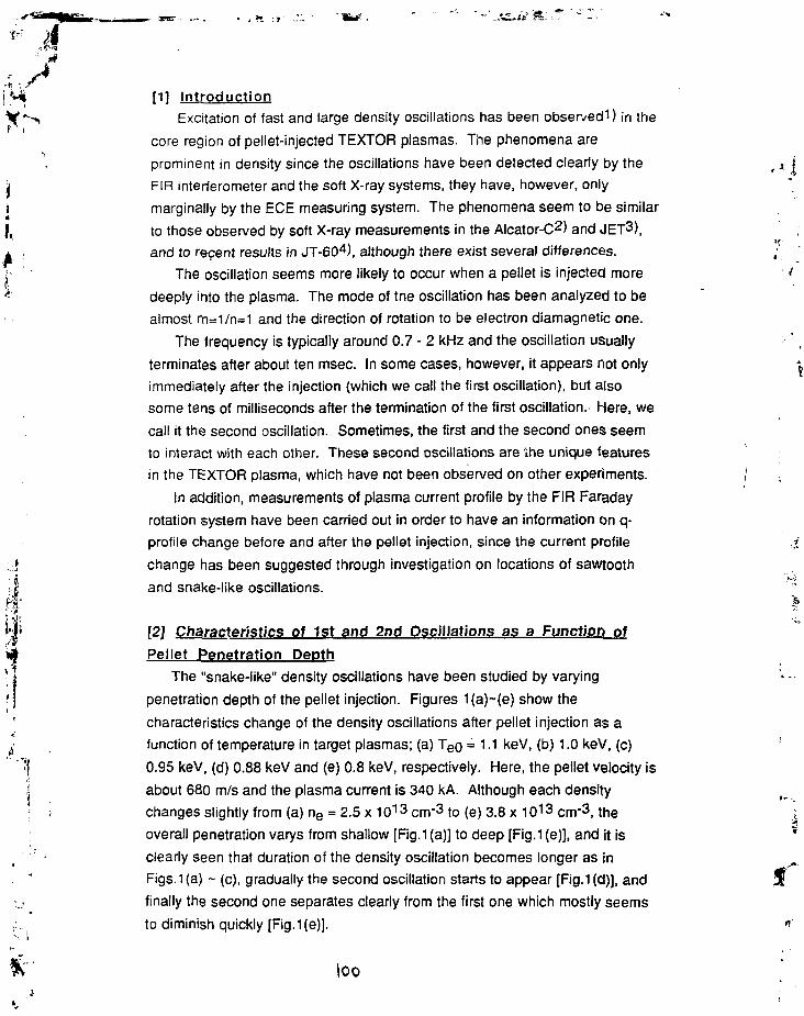
I
[1] Introduction
Excitation of fast and large density oscillations has been observedi) in the
core region of pellet-injected TEXTOR plasmas. The phenomena are
prominent in density since the oscillations have been detected clearly by the
FIR interferometer and the soft X-ray systems, they have, however, only
marginally by the ECE measuring system. The phenomena seem to be similar
to those observed by soft X-ray measurements in the Alcator-C2) and JET3),
and to recent results in JT-604), although there exist several differences.
The oscillation seems more likely to occur when a pellet is injected more
deeply into the plasma. The mode of tne oscillation has been analyzed to be
almost m=1/n=1 and the direction of rotation to be electron diamagnetic one.
The frequency is typically around 0.7 - 2 kHz and the oscillation usually
terminates after about ten msec. In some cases, however, it appears not only
immediately after the injection (which we call the first oscillation), but also
some tens of milliseconds after the termination of the first oscillation.- Here, we
call it the second oscillation. Sometimes, the first and the second ones seem
to interact with each other. These second oscillations are Ihe unique features
in the TEXTOR plasma, which have not been observed on other experiments.
In addition, measurements of plasma current profile by the FIR Faraday
rotation system have been carried out in order to have an information on q-
profile change before and after the pellet injection, since the current profile
change has been suggested through investigation on locations of sawtooth
and snake-like oscillations.
[2] Characteristics of 1st and 2nd Oscillations as a Function of
Pellet Penetration DepthThe "snake-like" density oscillations have been studied by varying
penetration depth of the pellet injection. Figures 1(a)~(e) show the
characteristics change of the density oscillations after pellet injection as a
function of temperature in target plasmas; (a) T e u = 1.1 keV, (b) 1.0 keV, (c)
0.95 keV, (d) 0.88 keV and (e) 0.8 keV, respectively. Here, the pellet velocity is
about 680 m/s and the plasma current is 340 kA. Although each density
changes slightly from (a) ne = 2.5 x 10¹³ cnr3 to (e) 3.8 x 1013 cm'3, the
overall penetration varys from shallow [Fig.1 (a)] to deep [Fig.1(e)], and it is
clearly seen that duration of the density oscillation becomes longer as in
Figs.1 (a) ~ (c), gradually the second oscillation starts to appear [Fig.1 (d)], and
finally the second one separates clearly from the first one which mostly seems
to diminish quickly [Fig.1 (e)].
loo

i'"*. V In order to verity tms tendency, more clear-cut experiments have been
' earned out, where the targe: plasma parameters have been kept constant but
only the pellet velocity has been varied by changing the driver gas pressure.
Typical results are shown in Fig.2, where the temperature and density are 0.95
, keV and 3.2 x 10'3 cm"3 being same condition as in Fig.1(c), however, the
• velocity is about 600 m/s [Fig.2(a)] and 750 m/s (Fig.2(b)], respectively. Thus, it
I seems to be obvious from the comparison of Figs.1 and 2 that the deeper
penetration of pellets into plasmas makes the snake-like density oscillation
* . more active, and eventually, its second oscillation more likely to occur. The
| phenomena might suggest that the deposited particles are trapped in a certain
region of core plasma, for example in a magnetic island near the sawtooth
inversion radius of the plasma. Locations of the snake-like oscillations will be
discussed in the next section.
The effect of pellet injection on sawtooth activities have also been studied.
Figures 3(a) and 3(b) show the dependence of penetration depth on
suppression effect of the sawtooth activity. In the case of medium penetration
as in Fig.3(a) which is almost the same plasma condition as in Fig.1(c), the
sawtooth activity has been slightly stabilized for about a 100 ms. On the other
hand, in the case of deeper penetration as in Fig.3(b) which is the same
condition as in Fig. 1 (e), it has been stabilized for more than 400 ms, and in
addition, clear and strong density peaking has been observed for several tens
of ms after pellet injection. These tendencies seem to be similar to those
observed in other several devices.
4i'jjj
[3] Faraday Rotation Measurements of Pellet-Injected Plasmas
and the Location of the "Snake-Like" Density Oscillations
Faraday rotation measurements of pellet-injected plasmas have been
earned out by using 9-ch FIR system for the first time. Motive force of the
measurement is to investigate possible current-profile modification after the
pei.et injection, which has been suggested from the results of soft X-ray
analysis of the density oscillations as mentioned later.
This is the first attempt of the measurement with respect to pellet-injected
plasmas. So far the signal-to-noise ratio is not adequate, which makes us to
have time resolusion of about 50 ms by averaging the signal. Whthin the
limitation of this time resolution, no detectable change of the poloidal magnetic
field and of the current density profile during pellet injection has been
observed. An example of the temporal behavior of the interferometer phase
shift ( r nedz) and of the rotation angle ( [ neBzdz) is shown in Fig.4. Here,
Fig.4(a) is the whole time history of the discharge and Fig. 4(b) is the time
lot

expansion of it with different beam position. [A slight difference of two traces
r i just after pellet injection (t = 1.54-1.6 sec) may be mainly due to the relaxation
of density profile.] Eventually, the global current distribution may remain
unchanged during pellet injection, although the possibility of small localized
» modification of it still exists.
• Locations of 1st and 2nd snake-like density oscillations have been
• analyzed from the multi-channel soft X-ray measurements. As can be seen
jfr . from the examples in Fig.5, the 1st oscillation is typically observed on ch. 23
i [the 3rd trace in Fig.5(a)], ch.29 [the 4th trace in Fig.5(b)] and within the two,
which corresponds to the outer edge of about 8 cm. On the other hand, the
2nd oscillation is typically on ch.22 [the 4th trace in Fig.5(a)], ch.30 [the 5th
trace in Fig.5(b)] and within the two, which corresponds to the outer edge of
about 10 cm. If these density oscillations have strong relation with q =1
surface, the movement of the location of 1st and 2nd ones may suggest a slight
movement of q = 1 surface, and thus, may suggest local modification of current
density profile.
In addition, change in sawtooth inversion radius has been observed during
pellet injection. In the similar manner with that mentioned above, the inversion
radius before the injection is about 10 cm, whereas the one after the injection
is about 8 cm, which are seen both in a deeper penetration case [Fig.5(a)(b),
corresponding to the case in Fig.1(d)] and in a shallower penetration case
; j [Fig.5(c)(d), corresponding to the case between Fig.1 (b) and Fig.1 (c)].
j | . The properties of the density oscillation phenomena seem tG be
J-rf! qualitatively similar in some machines [Alcator-C, JET, JT-60 and TEXTOR,
.# also in W7-AS&J], however there exist several differences in quantitative
v features. The phenomena might be explained by the persistent trapping of
j particles ablated from a pellet inside a magnetic island by some reasons6),1 ( however further detailed studies will be necessary to identify the mechanism.
1I References
| ; 1) K.N.Sato et al. : 19th EPS Conference (Innsbruck, 29 June - 3 July 1992)
; \ 2) J.Parker et al. : Nuclear Fusion 27 (1987) 853.
. u 3) A.Welleret al. : Phys. Rev. Letters 59 (1987) 2303.
4) Y.Kamada et al. :JAERI-M 90-123.
5) A.Weller: private communication.
6) S.l.ltoh et al. : Comm'ts Plasma Phys. Cont'ld Fusion 13 (1990) 141.
\O%

4
Si
Fig.2(a)i
Pellet
TEX TOO «.:g!'. £LEC.LI*E CE^SlTv
I
Fig.2 Characteristics variation of the densityoscillations by different pellet velocities withthe same plasria conditions as in Fig.1 (c).(a) Vp=600 nVs and (b) 750m/s.
JTEJOOB
Fig.3 (a) ™:;:: -,
Pellet
Fig.1 Characteristics variation of the "snake-like" Fig.3 Defference in sawtooth suppression effectdensity oscillations as a function of penetration by the difference in the pellet penetration depth,depth of pellet injection, (a) T e 0 - i . i keV, (b) 1.0 keV, ( a ) shallower, Te0«0.95 keV. ne-3. ix i01 3cnV3 .(c) 0.95 keV, (d, 0.68 keV and (e) 0.8 keV. (VP-680nVs] { b ) ^ ^ ^ ^ _ _3 ^ 1 3 ^ . 3

fitr-s-
1t
I,
I TEXTOP FARADAY ROTATIONBTEXTOR
Fig.4 (a) -52^23
retflflon anfllr j n k Bz
(beam position: x / a • 0.28)
T) phase shift j n . dz
(£ ) rotation angle: f n . Bz dz
FARADAY ROTATION
Fig.4 (b) -52Pellet
Fig.4 The first results of the Faraday rotation measurement in the pellet-inj acted plasma.(a) Comparison of temporal behaviors of © phase shift by interferometer i nd © rotation angle ofthe polarization of the FIR laser, and (b) its time expansion with different beam position.
Fig.5(a)H0B& 45*97
Fig.5 (b) Fig.5 (d)
Fig.5 Temporal behavior of multi-channel soft X-ray signals in two cases.
(a),(b) In the case of deeper penetration : Te0=0.88 keV, n"e=3.5xi013cm"3.
(c),(d) In the case ol shallower one : Te0«0.95 keV, ne=3.2x1013cm"3.
\0k

Vi^ 4 Strong magnetic fluctuations due to an ablatingr i 1
pellet, and fueled particle response to the SOLand divertor
iI ' • H.ZUSHI, T.MIZUUCHI, K.NAGASAKI, Y.KURIMOTOj , T.FURUKAWA, Y.SUZUKI, S.SUDO" , M WAKATANI
'*. • . Plasma Physics Laboratory, Kyoto University Gokasho Uji 611 Kyoto, Japan|, * National Institute for Fusion Science, Nagoya, 464-01.Japan
Abstract
Results of pellet injection experiments on propagation of cola dense plasmoids, related fluc-tuations, and its application to estimation of the effective connection length are presented. Asharp pulse-like density response is observed at the initial phase of density rise for edge fuelingcase. Characteristic propagation velocity is evaluated by a measured delay time and the lengthof aline from calculations of the field line tracing. During this phase bursts of magnetic (Bo) anddensity (with KxBv) fluctuations are observed and may be caused by a rapid equilibrium processof ablated plasmoid along the magnetic field line. Mode analysis results and good correlationwith Ha fluctuations are discussed from a point of view of resonant interaction between pelletablation and rational surfaces. By measuring the delayed response of the ion saturation currentat the divertor due to pellet fueling, it might be possible to estimate the effective connectionlength from the edge to the divertor and to evaluate the ergodicity of the magnetic surfaces nearthe edge. The effects of global confinement properties on parallel transport are discussed.
• *
J §1 Introduction
i'jj; In toroidal devices it has been recognized that confinement property is only determined by;,iy cross field transport. No attention has been payed on parallel transport because that it does not^ lead to a net loss if the magnetic surfaces are closed. However, interesting phenomena associated* 1 with parallel transport have been observed, for example, "snake" by the interaction between pellet' j and an island[l], "Marfe" by competitive process between parallel heat transport and radiationf ' loss with a negative temperature dependence[2]. Of course parallel transport dominates the•• density and temperature distributions along the field line to the divertor[3]. Especially, parallel* transport near the edge affects bulk confinement properties; Marfe causes the density limit, and
j * ^ good divertor is necessary to get H-mode plasmas.'I We study the phenomena related with parallel transport by using pellet injection. As aI result of pellet ablation a cold dense plasmoid is filled in the flux tube in a finite time in which] , a pellet crosses this tube. This plasmoid expands along the field line via parallel transport[4].i Finally these fundamental processes establish a new equilibrium state with different density and1 temperature profiles. During this equilibrium process(< TE or TP), steep density and temperature•j- , gradients exist on the tube and they relax. Thus, a sharp pulse-like density rise[5] or fast
1 temperature drop[6] have been observed.The purpose of this paper is (1) to analyze the plasmoid transport , (2) to study the proper-
ties of the related magnetic and density fluctuations, and (3) to apply delayed particle response
Ic?

t7
.1, rf.HNf *-•> : .-.• •;:.•; divert or to evaluation of the effective connection length from the plasma edge to the diver-
' •_• :. I:; '••'! pulse-like density propagation is shov/n and a comparison with results of the field line:.-.vi.'ig is discussed. In §3 bursts of B$ and nl are analyzed and a correlation with H^1 from the
' ;, = -!!'j; cloud will be discussed. In §•! the measured results of delayed density rise at the divertorj .•-:•• siiov.-n and Lejj is evaluated. The effects of global particle confinement properties on above
!>i:fnomena based on parallel transport will be discussed in §5. The conclusions are given in §6.
' : 2 Pulse-like density propagation>:.
I II7/D2 ice pellets are injected on the midplane along the major radius. The velocity of pellets<* is usually 400-600 m/sec and the size of pellets is 1 ?nm'x_(0.9-1.6) mm^l}. The line density is
measured with a far infrared interferometer (FIR) separated toroidally by HRQ from the pelletper'. H^'1 emission from a pellet cloud is measured at the opposite side of the injection port.Therefore, the time history of ffg'1 corresponds to the special pellet trajectory along the longeraxis of the elliptic cross section. The increment of the line density An/ is delayed with respectto //£'' emission. The delay time Tjeiay is in the range of 250 ns± 100 ;is in various plasmaconditions, which indicates that the particles fueled at the injection port propagate along thefield line of ~ 1:RQ with a velocity of 2.8 X 10⁴ m/sec. This velocity corresponds to the soundvelocity Cs = y/TeIM, where Te ~ lOeV.
A sharp pulse-like density response is typically observed in ECH plasmas, in which the par-ticlfs are deposited mainly near the edge. This pulse-like response is superposed at the initialstage of the normal density build up phase. Therefore we considered that this pulse-like re-sponse may be due to the result of propagation of a cold-dense plasma, ablated near the edgeregion close to the pellet injection port. Ref.[4] shows that the cold dense plasmoid, whichhas a density of ~ 1016cm~3 at the ablation point at t=0, propagates along the field line, andat t ~ 200 [is it propagates by ~ 10 m and its density is reduced to ~ 10licm~3. If thismodel calculation with plasma parameters^,. ='-5 x 1013cm~3 and Tc — 500eV) is valid for
',,i our conditions (1 x 10¹³ < ne(0) < 6 X 1013cm~3 and 300 < Te(0) < lOOOeK), observed pulse-like density response could be explained by the propagation of the cold-dense plasmoid, whichprecedes density uniformalization on a magnetic surface. In Fig.l, a peak value pulse of the
; | ; pulse-like density rise Anl is 1.36 xlO15cm~2 along the #6 chord, and it is twice as high asMi that of Ani i a " = nlalt" - nlbc'0TC (~ 0.64 X 10¹⁵C7rr2). If this Anl"ulse corresponds to a dense' j plasma localized along the length £ of ~ 10cm, it gives An t ~ 1014cm~3, which is consistentT with Kauffman's results. Although a pellet is injected from the outboard side of the torus andI initially particles are expected to be deposited there, pulse-like responses are observed along
n chords which are in the inboard side. In Fig.l, a plasma boundary is limited by a rail limiter1
1 inserted verticaUy along the longer axis of the ellipse and the head of the limiter corresponds toAili,(s R - Ro) = 1S.5 cm at the. pellet port. The magnetic field line tracing is done. The linesare launched at several positions along the major radius on the midplane at the pellet port and
" ••'*! are traced in both directions of clockwise (CW) or counterclockwise (CCW) along the torus. In\ ' Fig.2 a Poincare plot at the FIR port is shown. Since the FIR port is separated by 180 ' fromg the pellet port, this plot has a up-down symmetry. The #6 chord intersects twice the field lines.! I The one corresponds to the line starting from AR ~ 27.5cm which is in the lirriter shadow and
the other corresponds to that from AJ? ~ 17.0 ± 1.5cm. The #0 chord crosses the lines starting, from AR ~ 24cm which is also in the limiter shadow. In the limiter shadow we can expect; • that ablation of pellet is weak because of low incident heat flux due to a low electron tempera-
ture. In the case of no limiter insertion, in which the outermost magnetic surface corresponds toA/fc>jV/s=28.5cm, pulse-like responses are also observed along the # 0 and # 1 chords, as shownin Fig.3. These chords cross the lines which are launched from AR =23-25cm by 3-5cm inside

•: .• . .i.::n:::'.ost surface. Thus, we consider that observed pulse-like density response is due to the:.:o;jaaatio:i of the dense plasmoid fueled near the edge along the field line. Furthermore the.•.:;.-.':<:teristic propagation velocity is an order of Cs with Tc ~ I0el'\
'i-,3 Fluctuations during the pellet ablation phase
Strong bursts of magnetic fluctuations Bg are measured during the pellet ablation phase withMirnov coil arrays[Sj. These fluctuations grow rapidly after pellet injection with a delay timeof 50-100 us and last for several hundreds microseconds, which is much shorter than a timescale of 7/j or rp, as shown in Fig.4 . Since the amplitude of Bg seems to be insensitive tothe density rise An/'asc and B$ are damped when a new density profile is being established, aninterchange mode driven by VTP may not be a cause of Be- The frequency spectrum is analyzedby FFT technique, which shows several coherent peaks helow the Nyquist frequency of 166kHz. From cross coherence analysis between Mirnov coils, the poloidal(m) and toroidal(n)modenumbers are analyzed. The results are shown in Fig.5. The following modes with m/n=2/l,3/2, 1/1 are identified. The direction of propagation of these coherent waves are usually inelectron diamagnetic drift direction (m<0), but the mode rotating in the opposite direction isaiso observed. Thus, it is found that some parts of magnetic fluctuations consist of coherentwaves with low toroidal mode numbers. The mode rational number m/n corresponds to therational surface with ts =m/n. In this series of experiment e(0) is fixed to be 0.52 and t (a) isvaried from C.7 to 2.5 by the limiter. Since m/n value is always less than t(a), we consider thatthese coherent modes may be associated with corresponding rational surfaces and their transientbehavior is related to the rapid equilibrium process on the rational surfaces.
Bursts of line density fluctuations nl are also observed which are coincident with bursts ofBo- nl are measured by COi laser phase contrast method[9], which measures long wavelengthwaves with K ± Bv in our arrangement, but has no.special resolution along the COi beam path.The diagnostic port for COi is separated by ~ 45 ' from the pellet port. The nl precede the riseof nl at the FIR port, which suggests that fluctuations come from the pellet port. Hjf1 emissionalso fluctuates in time, although its time variation reflects the trajectory of a pellet. It has beenreported in Ref.[10] that dominant frequency of Ha is explained by "dark and bright" striationsdue to successive ablation from one flux tube to the neighboring tube, that is, v^jd^i wherevpct is the speed of a. pellet and dpei is the diameter of the pellet cloud. The coherence analysisbetween Ha,nl and Bg shows that they are coherent at several frequencies, ranging from belowVpei/dpet to above it, as shown in Fig.6. This fact suggests that some parts of these fluctuationsare driven by the same source and may be attributed to a rapid equilibrium process on the mag-netic surfaces and a resonant interaction between an incident heat flux on a pellet cloud and therational surfaces.
-§4 Delayed particle response to the divertor
A pulse-like density rise is also observed on the signal of ion saturation current /+ at thedivertors. Langmiiir probes are installed on the divertor footprints at several toroidal crosssections and are separated typically by ~ + 66 ' (CCW)/~-123* (CW) from the pellet port[ll].If the particles are deposited near the edge, they might be lost fast from the outermost surfaceand then transported to the divertors mainly along the magnetic field line. ECH plasmas aresuitable for this purpose because that a penetration depth is usually ~ a/2 and particles aredeposited mainly near the edge. The particle deposition near the outermost magnetic surface isstudied by shifting the outermost surface by Av ~ ± lcm. The line density along the # 0 chord

m
)• i *• :s measuroii. For i , . = Crm. this chord just toucli the outboard side of the outermost surfaceand for ^.. = -rlcm. this passes the outside the outermost surface. The density rise due to pellet
t injection is shown in Fig.7. The result shows that the particles are actually deposited inside the, outermost surface and even if a fraction of the pellet mass is ablated in the SOL, they cannotI reach the FIR port. Thus it can be expected that a fast, sharp and large rise in Ij is due to• the increment of the particle flow which originates from the edge region. The result is shown inI Fig.S. Ij increases rapidly, but is delayed with respect to the H^'1 emission. From this delay
time and an assumed characteristic velocity of Cs along the field line, the effective connectionk ' length Ltj- is evaluated an order of ~ irRo-;• ' When the particle deposition zone becomes inner far from the outermost magnetic surface\ which connects to the divertor, a delay time is expected to be longer by T± which is a charac-
teristic time for particles to diffuse radially to the outermost surface. We used a limiter for thispurpose and studied NBI plasmas in which the particles were deposited near the center. Theincremental line density distributions An/ i M £ (R) for <a>=9cm and <a>=21cm(no limiter) areshown in Fig.9. The result shows that particle deposition region is limited by the limiter. InFig.10. T,ieiay of A/+ at the divertor is plotted as a function of <a>. The about half of probes(denoted by open circles) show a monotonous reduction in ~ieiay with increasing <a> or decreas-ing the distance between the deposition region and the vacuum outermost magnetic surface (notthe limiter surface). This fact supports that Tje;al, ~ rj_ + TJJ. However, the rest of probes showa weak dependence of the deposition region and for this group Tjeiay ~ T||. The result suggeststhat some regions in the core connect directly to some parts of the divertor with £ e / / ~(2-5)XTTRO. Further investigation will be done on this point.
§5 Effects of global particle confinement on parallelparticle transport
.j We found that the pulse-like density rises in the core or at the divertor were affected by a
.."i change in the global particle confinement. It has been reported in Ref.[12] that a plasma heatedij_ by second harmonic cyclotron waves at the frequency of 106GHz has an improved particle con-*.•%• finement property compared with that by fundamental heating at 53GHz. In this improved statejjji the density is increased by ~ 20 %, and 7/™°" emission and /+ are much reduced. The responses,\f at pellet injection are shown in Fig.] 1 for both "improved" and "clamped" plasmas. The sharp^| pulse-like density rise is not observed on line density signals and ion saturation current. The* t former may be related to a change from a hollow deposition profile in "clamped" plasmas to a' j more peaked one in "improved" plasmas. However, an observed reduction in AIj and their time. ' evolution should reflect that improvement of global particle confinement affects the characteristic
1 propagation velocity of the particles flowing towards the divertor and an absolute value of the* outflux.
aj §6 Conclusions|, The phenomena related with parallel transport in Heliotron E are studied by using pellet1 injection. Some conclusions are given as follows.
i • ' ' (1) A sharp pulse-like density rise preceding the gradually increasing density rise is observed. " and is recognized as a propagating cold dense plasmoid along the field line.
(2) During the process for establishment of a new equilibrium state by pellet injection, bursts.• of magnetic and density fluctuations are observed. Some part of these fluctuations consist

M
of coi.-;>ient waves with low toroidal mode number.
(3) Good correlation between B$, nl, and lla indicates that some parts of Ha are caused bythe resonant interaction between pellet ablation and rational surfaces.
(4) The delayed response of If at the divertor is observed and the effective connection lengthis evaluated to be the order of JT.RO from the delay time measurement.
(5) The parallel transport observed at pellet injection is affected by cross field transport.
jt Acknowledgement
We acknowledge Mrs.K.Yaguchi and T.Baba for thire technical support on the FIR systemand the peliet injector. We are also grateful to Prof.T.Obiki for his encouragement and toHeliotron-E group for their supports. This work is supported by Grant-in-Aid for Fusion Re-search from the Ministry of Education.
References
I 1 ] A.WELLER, et al., Phys.Rev.Lett. 59 (19S7) 2303
[ 2 ] B.LIPSCHULTZ, ct al., Nucl, Fusion 24 (19S4) 977
[ 3 j F.WAGNER, K.LACKNER, in Physics of Plasma Wall Interactions in Controlled Fusion(Post D.E., Behrisch, R., Eds.), Plenum Press, New York and London(1986)
[ 4 ] M.KAUFMANN, et al., NucI.Fusion 26 (1986) 171
[ 5 ] D.K.MANSFIELD, et al., Phys.Rev.Lett. 66 (1991) 3140
[ 6 ] M.SAKAMOTO, et al., Plasma Phys.Control.Fusion 33 (1991) 583
[ 7 ] S.SUDO et al., in Tech.Comiltee Meeting on Pellet Injection, IAEA (Gut Ising,FRG,1988)
[ 8 ] H.ZUSHI, et al., 18th EPS (1991) vol.2, p.153
[ 9 ] K.TANAKA, et al., Submitted to J.J.Phys.Soc.
[ 10 ] R.D.DURST, et al., NucI.Fusion 30 (1990) 3
[ 11 ] T.MIZUUCHI, et al., 18th EPS (1991) vol.3, p.65
| 12 ] K.NAGASAKI, et al., 20th EPS (1993)

v £, »• -•»
' ' " " - " • • - • • " * " "
: — . -
i^. i j£ " ' ' ' • " :
• :
:
'e 1 6 . 0o
Cl 6 . 0
- 4 . 0
°2 ' § 0 . 0 2 8 2 . 0 2 8 4 . 0 1 8 6 . 0 2 8 8 . 0 2 91) . 0
Tim e ( m s )
2 0 0 0 . 0
1 6 0 0 . 0
1 2 0 0 . 0
8 0 0 . 0
•tO 0 . 0 ;
I
" 2 8~2~.<riTT.0~2 B~6 .0^2 8 8 7 0 2 9 0 . 0Tim e (m 3)
(1')
- 2 0 - 0 r
"S 1 6 . 0 fE
• 6 , 1 2 . 0
C 8.0~ 4.Or
°2'fi 4 .82 8 5 .02 8 5 .22 8 5 .42 8 5 .62 8 5 .8Tim e {m s )
2 0 0 0 . 0 I
1 6 0 0 . 0 j
1 2 0 0 . 0
8 0 0 . 0
4 0 0 . 0
A
" 2 8 4 . 8 2 8 5 . 0 2 8 5 . 2 2 8 5 . 4 2 8 5 . 6 2 8 5 . 8T i m e [m 3 }
Fig.l (a) ill and JI£cl for <a> = 15 cm.(#3 is center chord.)In (b) time scale is expanded.
( a ) = , = I . S ' J . M i ' 0 . 0 0 0 . H e ' . a ' Q . R . ! p l i a = D . D 0 0 C I ( b ) Bo = 1.30 .1)1=0.000 .
pcJIetport
. IOIS t a r t i n g ? o i r . ! = l D , 5 c s
Fig.2 Poincare plot of field lines which arelaunched at port the pellet,(a) side view (b) top view(#15.5 and #34.5 correspond to the pelletand FIR port respectively.)
\\O
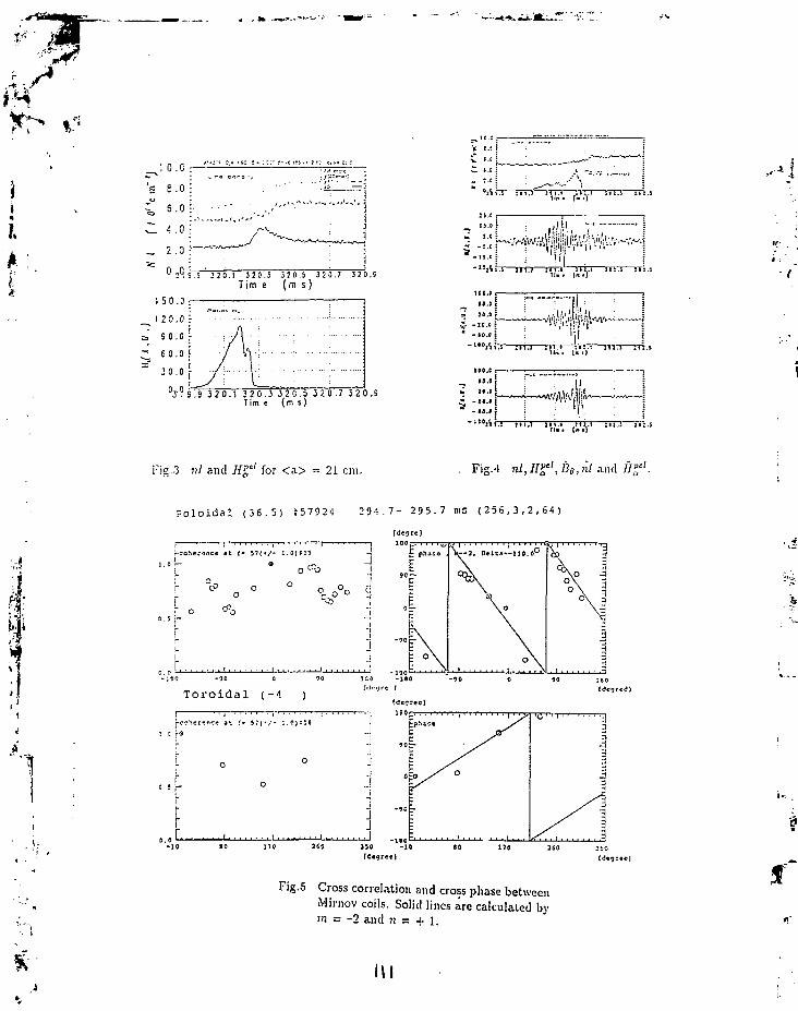
J O.C
: e .o
', 5 - °'. 4 . 0
2 . 0
50 .D
2 0 . 0
9 0 . 0
6 0 . 0
3 0 . 0
•A.'-—V>—J
J 2 O . I 3 2 0 . 3 3 2 0 . 5 3 2 0 . 7 3 2 0 . 9
Tim e (m s )
? S . 9 3 2 0 . 1 3 2 0 . 3 3 2 0 . 5 3 2 0 . 7 3 2 0 . 9T i m c ( m s )
TTp ii 1.1—rrrj—YT
It 1.1 TT2.S
Fis.3 n/ and 7fPe/ for <a> = 21 cm. Fig.4 nl,]I^',B0,nl^n<\ Ilf.
P o l o i d a l ( 3 6 . 5 ) i ! 5 7 9 2 4 2 9 - 5 . 7 - 2 9 5 . 7 m s ( 2 5 6 , 3 , 2 , 6 4 )
ID no 2CC 350 - 1 0 10 170 360 2*0
Fig.5 Cross correlation and cross phase betweenMirnov coils. Solid lines are calculated bym = -2 antl n = + l.

i4
I
I '• ,j
Crow coherenceH q 9 . O TTT. n,
f (kHz)
Cross cofwwicfl
JCO *CS
I ( k H z ) '
C2 0 E3 3 1C0.0
Cross coherence
"i ( k H z
Cross
43.3 ,ez.aI (kHz)
Fjg.6 Cross coherence between IIa, n! and Bobefore pellet injection {(a),(c)} and dur-ing peJlet ablation {(b),(d)}.(a) and (b) for Ha and 5$, (c) and (d) forlie, and nl.
Sr-Ti::.=:-;:-H. I . K I C..-J.1S2 *• C.C DI- CO I £!- 2- 11
("L-.VS CSWSITY CE!5/CM
23Z3-. a MV
Ik:
#3
# 0
#3
#0
527'.3
L - ^ • • ,!!?k #° n«
2746
TIMS CMSSC3
Fig.7 Density evolutions for Av ~ (a) -1 cm,(b) 0 cm, and (c) + 1 cm.

T~• . * • - * .
fif
i>.
•A
1
'E I ; . ;•s , s . :
2 5 . ;
2 5 .1
I C C
5.0
5 C O . 0
_ 4 O C . 0
^ - 2 O 0 . C
"" 1 0 C . C
0 , 4
"2te.i 2TO 2TT0 !TsT2 2Ts.T i m e ( m i )
2 8 S . E 2 ( 1 . E 2 E 9 . 0 2 C 9 . 2 2 8 9 . 1Tim 1 {n 1)
Fig.S / / at two difTerent divcrtor positions atpf.'ilet injection.
8.0
^ 6 . 0"to*
o
.J4.0>oo
2.0
0
o
o
o
ao
•
o
ooo
1
o
0o0
0o
i '
I ftcr pcait'ionKIN2 oIS7 •
•
""5.0 10.0 15.0 20.0 25.0< 0 >!n (cm)
10.0 -J
8.0 :
( a ) NL rise by peliel injection
2.0 :
0.0--15.0 -10.0 -5.0 0.0 5.0 10.0 15 C
KM
10.0NL rise by peliel injection
8.0-
2 . 0 -
-15.0 -10.0 -5.0 0.0 5.0 10.0 15.0R(cm)
Fig.9 Increment of nl at pellet injection(a) <a> = 21 cm, (b) <a> = 9 cm.
Fig.10 TMay vs. <a> in NBI plasmas.
113

DI *"• • - ! •
'.-! 'n rm—rrn—irn—rrr?—rri(V.)-
_ I B . 8 ;
" le.s j
Yt fa—firs—iTi.o1 "'"iifro—5?ro—rro.i
•9
(c)
': " I
•nb
i e o . t r -18.0 j
' t s . i E
• 300.1 i• I* j o o . e •
(-..]
11 S .1 IIS,4 ,11 J.I I t s . I J 11,(fin • (n •]
10.0 r—
10.0
560.0
- JOO.O
u 1«».O
IV.V
F i g . l l nl,Ha,I+ and rf pulse width
in (a) clamped and (b) improved plasma.
In (c),(d) time scale is expanded.

v £•-••As.iV.atu-
14MHD Activities in Pellet Injected Discharges in JT-60 and JT-60U
Y. KAMADA, R. YOSHINO, T. OZEKI, M. AZUMI and M. NAGAMINaka Fusion Research Establishment, Japan Atomic Energy Research Institute
Naka-machi, Naka-gun, Ibaraki-ken, Japan
This paper treats some topics related to MHD activities modified by pellet injection in JT-60and JT-60U, which also reports that the rational surfaces and islands behave as a barrier for particletransport. In JT-60 and JT-60U, discharges with deep pellet penetration are characterized by peakeddensity and pressure profiles just inside the q=l surface. With deepening pellet penetration, thesawtooth frequency becomes longer and the sawtooth crash changes its characteristics from fullcollapse to partial collapse and finally behaves as a non-reconnecting collapse. Shallow pelletpenetration can trigger an m/n=2/I mode which behaves like the snake oscillation; the particleconfinement inside the 2/1 island is much longer than the back ground particle confinement.
1. IntroductionThe steady state tokamak reactor must satisfy i) high steady confinement ( for example,
ELMy H-mode), ii) high pp to increase bootstrap current and iii) high PN to increase power densitywith iv) cold dense divertor plasma. Pellet injection is considered as a fuelling method suitable inreactors because of high fuelling efficiency. At the same time, pellet injection can be used for profilecontrol of ne, Te and bootstrap current. Then, the goal of pellet experiment is to demonstrate that thefuelling is compatible with above mentioned conditions i)- iv). To contribute to this work, this papertreats MHD behavior in pellet fuelled discharges, because the condition i) - iv) is sensitive to MHDactivities. While, from the view point of MHD physics, pellet injection is an interesting method tomodulate MHD characteristics. Based on these objectives, we report three topics; 1) strongly peakedpressure profile inside the q=l surface rs, 2) change in sawtooth crash mechanism and 3) the m=2snake oscillation. The detailed information of pellet injector is presented in ref. [1]. The injectionscenario and discharge conditions in JT-60 and JT-60U are given in refs. [2] and [3], respectively.
2. Peaking of Pressure Inside q=l SurfaceIn JT-60, highly peaked electron pressure pe ( or density) profiles were obtained [2,4] when
pellets reached near or inside the q=l surface rs and sawtooth activity was suppressed. Figure 1 (a)gives the time evolution for the profiles of Abel inverted soft X ray (SX) emission (~pe
2) for a NBheated limiter discharge. Pellets were injected at t=6.0sec. The SX-profile starts to peak inside rs
from t=6.2sec, from which pe(r) evolves only inside rs. Fig. 1 (b) is the results of scan of Ip and Btto survey the dependence of the width of the peaked portion of pe on q(a). The solid line indicatingrs for gas fuelling is written by rs=a/q(a) (a is the plasma minor radius). Therefore it is concludedthat pe(r) produced by pellet injection peaks inside rs [5]. We also found that the pressure gradientinside rs Jocaily reaches the marginal value for the ideal infinite-n ballooning mode. Whereas, thetotal pressure inside rs is consistent with the poloidal p limit for the internal n=l kink mode [6].Figure 2 shows an NB heated JT-60U discharge where two pellets were injected at t=5s into asawtoothing plasma. Figure 2(a) gives behavior of m=l oscillation on SX signal, where largeamplitude of SX/SX=73% (r/a=0.2) and 63% (r/a=0.1) were observed. Figure 2(b) shows profilesof SX(r) durinf. the m=l oscillation at two time slices with the phase difference of 180 degree, from

. • * 1 .
which we can confirm that the peaked SX(r) is produced just inside rs. The m=l oscillation of Te atr/;i-0.1 measured by ECE is shown in Fig.2(c), where the amplitude was only 9.8%. This resultsutziicsts that the peaking in pe(r) is mainly due to the peaking in ne and the particle confinementinside rs is much better than that in the q>l region.
In JT-60, improved energy confinement for the pellet fuelled plasmas was mainly due to the
peaked pressure profiles inside rs. The reduction in the sawtooth frequency has a strong relationship
with enhanced confinement. The contribution of the sawtooth activity to the global energy
confinement increases with decreasing q(a). This relationship is consistent with the extrapolation of
the L-mode confinement scaling including effects of sawtooth and internal inductance lj [7,8].
3. Characteristics of Sawtooth CrashThis section briefly reports the change in sawtooth characteristics by changing Pe(r) by
pellet. More detailed behavior of sawteeth after pellet injection was given in ref. [9]. Figure 3
compares time histories of the SX-signals (r=0, r=42 and r=56cm) and ne profiles measured by
Thomson scattering for four discharges with q(a)~2.3 (Ip/Bt=2.8MA/4.5T and 3.1MA/4.8T,
a=0.9m; JT-60 data). The pellet penetration becomes deeper from the top (1) to the bottom (4)
column of the figure. Numbers of pellets injected are (1) one, (2) two, (3) four and (4) four. The
penetration depth of the last pellet for the four discharges are (1) 0.7m, (2) 1.12m, (3) 1.4m and (4)
1.6m. In these discharges, peaking of pressure evolves inside rs. Therefore, to estimate the effects
of peaked pressure profile on the sawtooth activity, we use Ppi (the poloidal p value defined inside
r s ) .Values of j3pi are (1) 0.07, (2) 0.22, (3) 0.24 and (4) 0.35 at the time of Thomson scattering
measurement. With deepening the pellet penetration , ne(0)/<ne> and Ppi increase, and the
following tendency of the central MHD behavior is observed;
i) Sawtooth period increases. Amplitude of the m=l oscillation increases. Number of sawtooth with
successor oscillation increases.
ii) Sawtooth is suppressed for a long time (<1 s) and the enhanced m=l mode continues for <1 s.
iii) Both sawteeth and m=l modes are almost suppressed for ~l~1.5s except occasional small
partial sawtooth in the early phase after pellet injection.
The change in crash mechanism is compared in Fig.4. Figure 4(a) shows the SX-profiles
just before and after a sawtooth crash for the shallow penetration (Fig.3(l)), where the central part
of the SX-profile (r<30cm) is almost flattened. Such sawteeth often have precursor m=l oscillation
and very small or no successor oscillation. Figures 4(b) corresponds to medium penetration
(Fig.3(2)). The m/n=l/I oscillation appears continuously before and after the sawtooth crash. After
the sawtooth crash at t=6.4115sec, the radial position where the 1/1 oscillation becomes maximum (
ipcak ) anc i t n e outermost radius where the m=l activity is observed (roul) move inward with the time
scale of-10msec which is in the same order of the resistive diffusion time and is much longer than
the crash time (~400|isec). The distance rout-rpeak is almost unchanged. These observations mean
that the q=l surface and the island survive during the crash and the central kinetic energy is not
released completely at the crash. The similar behavior of the m=l continuous mode was also
observed on JET as the snake oscillation [10]. The differences and similarities between the m=l
(16

oscillation observed here and snake oscillation is discussed later. Figure 4(c) shows time history of
cor.iour plot of the SX intensity profile in case of Fig.3(3). It can be observed that the shift of the
\ q=! surface becomes small and the amplitude of the successor oscillation becomes large compared
wi;h those in the case of Fig.4(b). Figure 4(d) corresponds to the deepest penetration where the
sawtooth activity is suppressed within - Is . In this particular discharge, the plasma core dose not
rotate in the decay phase (t=7.2~7.7s) of the central SX emission. The core shifts following the
m = l displacement, but behaves as a rigid body during the crashes (crash time~300n.s). The released
SX-source is. very small. Figure 4(d) also shows two SX profiles just before and just after the
crash, and profiles of the radial displacement %r at 5OJJ.S and 300|is after the beginning of the crash.
The profile of cr is almost the same during the crash and the shape seems to be similar to that for the-
conventional ideal m=l mode [11] rather than that for the quasi-interchange mode [12].
In summary, with deepening pellet penetration, the sawtooth frequency becomes longer and the
sawtooth crash changes its characteristics from full collapse to partial collapse and finally behaves as
a non-reconnecting collapse.
4. m=2 Snake OscillationFigure 5 shows the m=2 oscillation triggered by pellet injection (OH discharge). In this case,
pellets were injected just after the ramp-up phase of Ip, therefore, the current profile is relativelyflatter. A large coherent mode starts just after the second pellet at t=2.48sec (Fig. 5(a)). Figure 5(b)gives the structure of the mode, from which the poloidal mode number can be identified as a m=2mode. In Fig.5(c), a large amount of the SX source is observed around ch.9~16 (r=53~28cm).Figure 5(d) shows time traces of rTe measured with two FIR interferometers viewing vertically atr=50 cm and r=-50cm. Both density fluctuations are in-phase, which supports the poloidal modenumber is even. With these results, a large amount of the injected density is trapped inside the m=2island and the particle confinement is much better (~1 order of magnitude) than outside the island.
The m=l snake oscillation [10] in JET suggests good particle confinement inside 1/1 island.From the results in JT-60 and JET, we can conclude that the magnetic island has the generalcharacteristics of good particle confinement.
5. DiscussionFor pellet fuelled discharges, sawtooth crash time tc r tens to increase with increasing ne. If
the crash is an ideal instability, the increased xcr may be explained by the change in Alfven time. InJT-60, the magnetic Reynolds number (S) and the resistive diffusion time (1R) for pellet dischargeswere about -1/10-1/20 and -1/4-1/8 of those for gas fuelled discharges, respectively. If thesawtooth is caused by the m=l resistive instability and the q-profile for pellet fuelled discharges issimilar to that for gas-fuelled discharges [13], the growth rate have to increase because of the
; reduction in S. Experimentally, however, the sawtooth crash time increased. The observation may
mean the sawtooth crash after the deep injection is not the resistive mode. The question is why thereconnecting mode is stabilized by pellet. If the sawtooth period can be described mainly with theresisdve diffusion time [14] in the central region, the period for the pellet discharges must be shorterthan gas-fuelling, because, generally, the central Te for the pellet discharges are lower than gas-

/j :i;elj:i!i!. The increased sawtooth frequency for shallow penetration (Fig.3(l)) can be explained withr* i this scenario. On the other hand, for peaked density profiles (Figs.3(2)~(4)), the extended sawtooth
period cannot be explained with resistive diffusion time. Conclusive results for the reason of the
enhanced sawtooth period and the stabilization of the reconnecting mode are open questions.j Concerning the similarity and difference between the m=l oscillation reported here and snake1 oscillation in JET [10]. The main physics of the snake oscillation satisfies the following conditions;j| i) The m=l island is produced by the pellet ablation itself by the local ihermal temperature
perturbation [15]. ii) High density is sustained inside the m=l island without any apparent densityV . source except the initial large source by pellets, iii) And the island topology survives for a long timej, compared to usual particle diffusion time, iv) The structure survives even through the sawtooth
crash. In JT-60, i) has not been observed. For example, in discharges shown in Fig.3(2), (3) and(4), no m=l oscillation is observed in the early phase after the pellet injection. Therefore the largetn=l oscillations treated here are not produced directly by pellet ablation. Concerning ii), ourobservation is that the particle confinement inside the q=l surface ( not inside the island) is muchlonger than that in the outer region (q>l). The large m=l oscillation on the SX profile starting at0.4~0.8s after injection may be caused by the density fluctuation. However, it is not clear whetherthe high density is confined inside the island or inside the shifted core. Our observation satisfies iii)in some cases and iv) in many cases. However, the property iv) can be observed even in the gasfuelled discharges as the set of the precursor and successor oscillations around a sawtooth.
The shallow pellet can destabilized these medium m/n MHD activities as shown in Sec.4 andalso affects ELM activity. In addition, the density limit is an edge density limit [16]. Therefore,concerning the shallow pellet fuelling in the tokamak reactor, we have to figure out the optimuminjection scenario aiming at the steady state operation with high confinement, high pp and high PN
'-•i with cold dense divertor plasma in the future JT-60U experiments.
j | , REFERENCES(Jji [1] H. Hiratsuka, et al., this workshop.S9 [2] Y.Kamada, R.Yoshino, M.Nagami, et al., Nucl. Fusion 29 (1989) 1785 .^f [3] R. Yoshino, et al., this workshop.i~ [4] Y.Kamada, et al., in Plasma Physics and Controlled Nuclear Fusion Research , Proceedings
of the 13th International Conference, Washington, 1990 (IAEA, V i e n n a ) , Vol.1, p .291 .' [5] Y .Kamada, R.Yoshino, M.Nagami, et al., Nucl. Fus<on 31 (1991) 23 .
[6] T.Ozeki , M.Azumi , Y.Kamada, et al., Nucl. Fusion 31 ( 1 9 9 1 ) 5 1 .. [7] Y. Kamada, T. Takizuka, M. K i k u c h i , et al., in Plasma Phys . Cont. Nucl. Fusion Research. (Proc . l4 th Int. Conf., Wurzburg, 1992) IAEA-CN-56/A-7-13 .
J* [8] Y. Kamada, T. Takizuka, M. K i k u c h i , et al., Nucl . Fusion 33 (1993) 225 .j [9] Y. Kamada, T. Ozeki and M. Azumi, Phys.Fluids B 4 (1992) 124.:] [10] A.Weller , A.D.Cheetham, A.W.Edwards , R.D.Gill , A.Gondhalekar , R.S.Granetz , J .Snipes,| and J .A.Wesson, Phys. Rev. Lett. 59 2303 (1987).; [11] M.N.Bussac , R.Pellat, D.Edery, and J.L.Soule, Phys. Rev. Lett . 3 5 1638 (1975).I [12;| J .A.Wesson, e t a l . , in Plasma Physics and Controlled Nuclear Fusion Research , Proceedings
, • of the 12th International Conference, Kyoto, 1986 (IAEA, Vienna, 1987), Vol.11, p . 3 .•'; . [13] R.Yoshino, Nucl . Fusion 29 2231 (1989).
' „ [14] Y.Kamada, et al., 'Sawtooth Frequency in DIII-D' G A - A 2 0 6 1 1 , General Atomics 1992.[15] G.Kurita, et al., in Plasma Physics and Controlled Nuclear Fusion Research , Proceedings of
the 13th International Conference, Washington, 1990 (IAEA, V i e n n a ) IAEA-CN-53 / D-4-1 .[16] Y. Kamada, N . Hosogane , R. Yoshino et al., Nucl Fusion 31 (1991) 1827.
W8

, * l ;•»
i
( 3 ) „ c(ai=3.3. Pabs=13.9MW
• 9 0 - 6 0 - 3 0 0 30 60 90
(b) T(CITl)
0.5
Fig.2 : A JT-60U discharge where pellets were injected at t=5 sec:(a) Behavior of m=l oscillation and a sawtooth crash measured by SXdiagnostics for four chords of r/a=0. 0.1. 0.2 and 0.3. (b) Profiles ofSX(r) during the m=l oscillation at two time slices with the phasedifference of ISO degree, (c) the m=l oscillation on the Te trace atr/a=0.1.
Fig.l : JT-60 data: (a) Time evolution of the Abel inverted SXemission profile for a NB-heated 2.1MA limiter discharge from l=6.2slo 6.5s. Pellets were injected at t=6.0s. (b) Dependence of the width of(he peaked portion of the electron pressure on q(a). The solid lineindicates rq=j for gas fuelled discharges written by rq=] = a/q(a).
Fig.3 : JT-60 data: Timehistories of the SX-signals( r=0. r=42 and r=56cm) andne(r) for four pellet injecteddischarges (l)-(4) (Ip=2.8-3.1MA. Bi=4.5 -4.8T andq(a)-2.3). Pellet penetrationbecomes deeper from the top(1) to the bottom (4) column.

. ' * • . A - . .
7 YS
sx/sx•- b ° 2 D"
SX Intensity (A.U.) Q)
<
(
V
>
S C S S SX UITEI'SITY (*.U.| Q
3 8 2
11"
SX-IHTBHSITY (A.U.)
DISPLACEMENT \ (A.U.) Pill POSITION: r (cm)h M toO O O O
H
fll
v>in£)
O
7.25
o
7.3
- \ \ \ \
\
lil.J
7-- ".• is o TJ on o w ' " ^ T I ' " & wi o t.' • i •. " ^
a s S: "• s ^ . " 3 n n , o ; r-
§• ? ft s - < K 5 - s - g g - . - " :;
° 2 3 X Q5- 3 -2- "
P 5-t; o
? T- ^1 D
a s
" ^ w 3 a
-• II § II °rr — 3 — S
SX-INTENSITY (A.U.)
CD
r (in) T'X i n i i M i s i i y
11
:%...j.......
0
1
I1
J
.
s:
3'
sec'
pi

pf ... 15* IAEA Techr.icai Committee Meeting on Pellet Injection
* ~* % I Sar-M Fusion Research Establishment, JAER1, Japan, May 10 -12,1993))
Fuelling of JET H-mode and Limiter Plasmas by Deuterium Pellet Injection
CLL Schmiritfa'l. D Bartlett, L Baylor (b), M Bures, A Edwards,
M Gadeberg, T Jones, P Kupschus, P Lomas, P Morgan, H MorsL P Nielsen,
J O'Rourke, G Sadler, DFH Start, P Stubberfield, A Tanga, D Ward
JET Joint Undertaking, Abingdon, Oxon, 0X14 SEA, UK
(a)Princeton University.Princeton NJ, USA;(b) ORNL, Oak Ridge TN,USA
This paper describes JET multi-pellet fuelling experiments conducted using a
range of pellet perturbations in L-mode (limiter) and H-mode (x-point) plasma
configurations heated primarily by ICRH.
A retained mass fraction or fuelling efficiency of 0.4 to 0.5 is typical of pellet
fuelled discharges using auxiliary heating and utilizing shallow pellet penetration
during the fuelling sequence. The radial distribution of the retained pellet mass, the
effective pellet particle source, is shifted outward in minor radius when compared
to that predicted by the standard ablation models.
Small and moderate pellet perturbations, N e i / < ne > less than or ~ 1, with shallow
penetration produce density profiles which remain broad. If the profile is
represented by the expression n (r)= n (0) (l-(r/a) ) a then a < 0.5 .. Sawtooth
oscillations persist in these discharges and can transport deposited pellet mass to
the plasma core particularly in cases of strong density profile inversion
immediately following the pellet event. Perturbations of this magnitude can be
used in limiter and H-mode discharges near the density limit. In H-mode
discharges under these conditions the pellet event can coincide with a transition to
a period of L-mode confinement.
| S L |

FIG i
Outline
• Fuelling - Next Machines
• Density EvolutionExtended Pellet Fuelling Sequences
- total particles - pellet source- profile evolution - core transport
• Fuelling at High Density- pellet perturbation near density limit
• Fuelling of H-modes- impact of pellet perturbation on H-mode
GLS - P2pers-Naka_93_JET-Rl-Ph 2of 5

Fuelling studies - Consider 4 Dlasma regions
Confined Plasma
CoreConfinementZone
S
PelletFuellingZone
ncore • Pellet
eparatnx
BoundryPlasmaZone
nbdry
DominantSource
•DiffusivityCritical
X
DivertorPlasmaZone
• RecyclingDominantSource
1
• Density at separatrix, n .^ limited by Tokamak density limit
• Radial extent of pellet source and Transport in PFZ determineGradients accross PFZ
• Gradients in Pellet Fuelling Zone determines core density,ncore' anc* m f l u e n c e s particle losses from core, pumping
rates
REFERENCE: W A Houlberg, S E Attenberger, M J Grapperhaus
GLS - P»pers-Naka_93_JET-Rl-Pl: 3 of 5
1*3

HG 3
Anticipated Penetration vs Speed and Pellet Size - ITER
T(0)=23keV
<ne>=1.6xl0
H
D
•
1%
5%
25%
up(km/s)
• extent of pellet fuelling zone determined by effective pelletparticle source - pellet penetration depth and radialdistribution of pellet mass
• R = 7.75 m, a = 2.75 m , K = 1.63
• 25% perturbation represents 8.5 mm diameter pellet
REFERENCE: W A Houlberg
CIS - Papers-N«ka_93_JET-R 1 -PI: A of 5

i'U S '-I- -.:
Variation of fusion power with <T>
Suoershoi Density Profile Shane
UJQ
trLU
oCLzoCOZ)
JE) H-mods Density Profile Shape -
i i i i i i
8 10 12<T|>n (keV)
14
• Other next devices - higher aspect ratio - lower Ip - larger
shaffranov shift - smaller volume - possibly larger relative
perturbation (A n / < n > = 0. 25 to 1. 0 , X / a = 0. 25 to 0. 5)
• Neutron rate modulation potential issue
• Little change in fusion power, <T> = 8to 14 keV
• Over this range adiabatic pellet perturbation not change fusion
power
• Peaked Profile Improves Performance
GLS • Papers.Naka_93_JET-RI-Pl: 5 of 5

1
FIG 5aik at JET pellet fuelling results
• Effective source - A/a = 0. 25 - 0. 5
• Pellet perturbations, n j / < n >. from 10% to 100% •
Begin with:
Radial distribution of Pellet Source in Pellet Fuelling Zone
- radial distribution of effective uellet source
Retained Mass: For pellet fuelling experiments, the measured retained mass and its radialdistribution following the pellet event are the quantities of interest. The total mass retained inthe present experiments has been determined from the increase in plasma electron density, •-•assumed to be symmetric poloidally and toroidally, as measured some 3 to 40 ms following thepellet event. In JET, minimal change in the total particle content beyond that associated with the ,pellet event itself occurs on this time scale. The retained pellet mass can vary from <40 to 100%of the nominal pellet mass. A retained mass fraction or fuelling efficiency of 0.4 to 0.5 is typicalof discharges using auxiliary heating and utilizing shallow pellet penetration during the fuellingsequence. The figure shows the fuelling efficiency for the three pellet diameters used in the JET >.experiments. A reduction in retained pellet mass from the nominal value occurs for all pelletdiameters. Similar results have been observed on other smaller tokamaks using pellets in theranges of 1 to 2 mm diameter. Little energy loss appears to be associated with this mass loss, >-.however, the effect muse be considered in establishing the pellet perturbation and panicle source.Presumably in a high recycling environment, the lost pellet mass would immediately form a partof the recycled flux.
sGLS - Papers-Naka_93_JET-Rl.P2: 1 of 5
\u

r A
A
i
1
4
i
RG 5b
Retained Mass Fuelling Efficiencv
- 0 . 8 —
I I 7Ja < 0.7
< 0.2 —
0
0.7
AA
Nominal Pellet21 21
0.9 x 10 3.0 x 1010x10
21
2.7mm 4mmPellet Diameter
6mm
•Fuelling efficiency reduced as pellet penetration diminishes•Non central fuelling - 50% of mass retained
mass observed in divertor - local pressure increase•Examine radial distribution of pellet deposited mass
(effective source)
GLS - P»pers-Naka_93_JET-Rl-P2:2 of 5
127

Density Increase in X-point Region at Pellet Injection
I
CO
?. 50
25
(£)
.150
XPUB/6
PELLETCROSSES
LCFS
=26570
14.151 14.152 14.153 14.154
GLS - P2pers-N«ka_93_JET-Rl-P2: 3 of 5

^ J Kf!:-<-tive Pellet Source: Pc'.'.z: even: in ihis sequence proceeds through iv.o phases followingp i .":•_.-:.-.-ra::on of the peiie: in ::.£ iaur.cher. In JET. ;he duration of a peiiet event is roughly j to 2
rr.: During the first phase, the peiiet penetrates the confined plasma volume. The ablating pelletrr.?.:.- acts to attenuate the erergy fiux incident on the peiiet reducing iht ablation rate. The
b , deposited mass is assumed to be ionized locally. During the second chase, this deposited pelletI '• mass redistributes itself symmetrizing the pellet mass perturbation in both the toroidal and* poioic'al directions. The n corral gas shielding model or its extension to the neutral gas and' ' plasma shield model are commonly used to describe the ablation process. The symmetrizingA • process is assumed to proceed widiout radial transport. Although the models can be adjusted to'{' ' reproduce the penetration depth obtained in JET, and hence to reproduce the ablation rate* integrated over the pellet trajectory, there are differences between the radial distribution of the
deposited mass predicted by the model and that observed in fuelling experiments. Thesedifferences could result from an incomplete description of the ablation and shielding process orfrom a breakdown in the assumption that no mass flow takes place across flux surfaces duringthe symmetrizing phase of the pellet event.
The radial distribution of the retained pellet mass represents the effective pellet particle source.A:; illustrated in the figure, in JET experiments this effective source is shifted radially outwardwhen compared to that predicted by the standard ablation models. The maximum perturbationoccurs at larger minor radius than predicted and the effective source near the plasma core at theend of the pellet trajectory is less than predicted.
CLS - Papers-Naki_93_)ET.Rl -P2: 4 of 5

v A
FiG 6b
Effective Pellet Source Function -Measured Mass Deposition
ORNL-DWG S2M-2312 FED
T 1.25
O-J
o
•^ L O Oc5
5 0.75a:
Oi^ 0.50
iCO
> 0.25 r
b
3.0 .2 3.4 3.6 3.8 4.0 4.2
d N rr / dt inferred from density profiles
Ablation rate calculated - modified Neutral Gas Shield
• dNeff/dt / NGS+ > 1 at T e < 1 keVdNeff/dt /NGS+ < 1 a tT > 1 keV
• Given anomalies, examine actual extended fuelling sequencedata for extrapolation to next devices
GLS - Papers-Nzk»_93_JET-Rl-P2: 5 of 5

•J a
FS'.'.::J oi 1.1 -:::. ^:i:r.-j:cr ::2ve bee.- c:--iovec to simulate a -"ossible ITER sready stare•ci.\\7.% ^csnario i:s:ng srrzii density pen^rbarions of from 20 io -:0%. An iniegrated pelie:pinicis :r_x of I.V x 10 '-vas injected usins 32 pellets over a;: S second period (figure).Average reiained mass fuelling efficiency was 40%. As shown. ;ne time evolution of :hedischarge ioial particle content can be modeled usins ihe average vaiue of the retained mass foreach pellet perturbation, combined with a decay time for the retained mass, which increaseslinearly from 0.25s to 1.75s during the fuelling sequence. This increase is greater than that of thepiasmB density. ' ~
i -
• I
CIS - Papers-Naka_93jnET-Rl.P3:1 of 4

• a r , ••*-
FIG 7
8 Second Pellet Fuelling Sequence - ICRF Heating - 3 MA
NominalPellet
32 Pellets- 4 Hz-- 8 seconds
01 0 Time (sec) 1 5
1
2.7mm - ITER like perturbation - nDej/<ntot>=0. 2- 0. 4Retained Mass:0JU©ri5~- Penetration A7a = 0.5
(6. M 72
Integrated pellet particle flux of 2.9 x 10" particlesRadiated Power Fraction maintained low
GLS - Papers-Nika_93_JET-Rl-P3: lot 4

J
8 Second Pellet Fuelling Sequence - ICRF Heating - 3 MA
l
Total Particles
(xlO
ModelPellet Increment
1.2 2.4 3.6 4.8 6.0 7.2 8.4 9.6 10.8 12.0 13.2Relative Time (sec)
i * increases during fuelling sequence
If Constant x ~ 50ms then R increases from 0. 80 to 0. 97
GLS • Papers-Naka_93_IET-RI-P3: 3 of 4

I
IIIt-
|4.3keV i2.8keV ; 1 keV•
AfterPellet
,••*
Radius ( m )
Pellet penetration to r/a ~0.5, outside the sawtoothinversion radius, was generally obtained.
The neutron rate was unchanged by the pellet event,confirming there was little perturbation of the plasmacore
Deposition profile estimated from abei inversion- limited number of radial measurements for estimate ofpellet mass deposition-modest inversion of the density profile immediatelyfollowing the pellet event.-profile then relaxes on a 100 ms time scale to shape of
the form ne(r)= ne(0) (l-(r/a) 2 ) 0 ' 5

• • * : .
4 r;;r;i Pellet Perturbation: ?e::s: penetration is extended ;o within the sawtoc:!: inversionr;.::.:s Approximately a 209c crop in neutron rate occurs with Dsilet injection corr.^ircd wich a5':"- riscrsase at a sawtooth crash. Note that in a higher temperature device link change in;-.c-.::r>-j~ rate would occur on pellet injection, due to the adiabaric nature of the pellet perturbationand the proportionality of neutron rate to pressure (T > 8 keV). The presence of :• ?cViz: sourcewitnm tne inversion radius is important since it allows the sawtooth to provide a mechanism byv.h;cr. pelJer mass is delivered to the plasma center. This effect is more clearly seer, when theneutron rate is scaled to remove the temperature dependence of the reaction rate (figure). Thenrst sawtooth after each pellet event produces the largest increase in core deuteron concentration,as indicated by the scaled neutron rate.
The density profile after the pellet in the figure represents those seen in the 4 i-m case. Theprofile is more strongly inverted than that following the smaller 2.7 mm perturbation. Theinverted profile again relaxes on 100 ms time scale.
Hi°h Density: As the density limit is approached, moderate pellet perturbations can still be usedin conjunction with the sawtooth to fuel the plasma core (figure). Since the pellet size was fixed,the nominal pellet perturbation decreased during the fuelling sequence with increasing Nfrom 130% to 40%, while a radiated power fraction < 40% was maintained. Retained massfuelling efficiency diminishes siighdy at higher input power (22 MW) but remains >50 % even athigh density.
The density at 3.9 m during and following the fuelling sequence approaches the value n(edge)-B-J-/R 2.37 P '^ proposed as a nominal limit. The density immediately following the pelletperturbation is likely to be higher than the values shown, since only the time point at 7.5simmediately follows the pellet event. Density profiles are broad with a ~ 0.1 .
GLS - Papers-NaJ;a_93_JET: 1 of 5 '"*
fC

• • : «%- * • - •
Density Profile - 4mm PelletsFIG 10
0.6
ii—
o~ 0.4CvJ
oo
1—
0.2
n
I I
JET•#26670
tpeliet = 14.152 svpellet = 1153 m/s
i i l
/ i -/ t = 14.155 s
t= 12.955 s^.T
A n t " 1
"\ PELLET PENETRATIONT , , ,
i
\
\ v
\\\\3.0 3.2 3.6 3.8
R(m)
4.0 4.2
4mm - npel/<nt()t>=l.-1.5
Retained Mass:0.3- 0.5 - Penetration X/a. > 0.5
Integrated pellet particle flux of 2.9 x 102" particles
GLS - Papers-Naka_93_JET: 2 of 5

FIG 11
4-, NominalPdiet
6 Pellets-1 Hz- 5 secondsDataModef
i\ (Neutron Rate / Tp (0)3)1 /2
Time (seconds) 10-5 11
Radiated Power Fraction maintained -
:p* increases during fuelling sequence as for 2.7mm
• Sawtooth in Presence of Inverted Density Gradient moves
Mass Deposited by Pellet into Core
GLS • Papers-Naka_93_JET: 3 of 5

i ,;
FIG : :
Large Perturbations Can Be Used Near Density Limit
6 7 8 9 10Time (seconds)
11 120
Density Perturbation n , / < n£ > from 1 . 3 to 0 . 4near density limit ^
GLS - Papers-Naka_93_JET: 4 of 5

M
FIG 13
Density Profile - Pellet Fuelling at Near Density Limit
2 3 4Radius ( m )
1
• High Density fuelling sequence approaches nominal edge
density limit n (edge ) = B T / R 2.37 P ° " 5
• Points show analytic profiles of the form:
8.5x10 1 9 (1 - ( r / l . l ) 2 ) a
GLS - P2pers-Naka_93_reT: 5 of 5
• ' * : •
- I-'ueliim; of H-mufi- plasma - response of H-mode to per turbat ion
ii-mod'; Operation- I- high density H-rnode plasmas, iT!c<ier2te pelis: penurbarions can also be•\'.zc. D-t as dens::y approaches the density limit transitions back :o L-:nocc confinement mayro::ow me pellet psroirbanon. Trie figure shows an H-mode pellet fuelling sequence withnominal pellet perturbation of 50%. Retained mass fuelling efficiency was also 507c. Following•r.e rirs: oeilet penurbations the volume average density increases but edge density remains <5 x10" m J and little perturbation in the H-mode conditions is observed. With subsequent pellets,r.ov.rever, edge density following the pellets rises above 5 x 10 m ° . A period of L-modeconfinement of increasing duration then follows each pellet event. During this L-mode phase,levels of, and fluctuations in, the Da emission increase as do radiation losses from the x-pointplasma. Although a momentary loss in RP power following the pellet event may contribute toihc the loss of H-mode, the plasma response suggests that choice of pellet size and frequencymight 'oc used to control H-mode performance in high density plasmas.
CIS • Papers-Naka_93_JET-Rl-P5: 1 of 6
*°
f

• A 1 -I • «
i l
5"I
FIG 14
4 mm Pellets Into H-Mode PlasmaTotal Stored Energy and Global Confinement
H-modelL Hi L H L H L-mode H-mode0
Time (sec) 13 14 15
Transition from H to L Mode occurs following pellet eventL-Mode Duration Increases Through Pellet Sequence
GLS - Papers-Naka_93_JET-Rl-P5: 2of 6

ixJ
r
9
FIG j-r
4 mm Pellets Into H-Mode PlasmaGlobal Power Balance and D Lisht
a ~
Pellet p p P P
L El L-mode H-mode
\ PRad(X-Point)
Tlme(sec) ! 3 1 4
Strong Increase in Radiated Power from X-Point Regionfollowing pellet eventDuration of X-point radiation burst increases duringsequenceD a Increased During Same Period
GLS - Papers-Naka_93_JET-RI-P5: 3 of 6

r" p
FTC r5
4 mm Pellets Into H-Mode PlasmaEdge Density and Temperature
-1 Density i
H-mode (*( L-mode B
10 11 12 13Time (seconds)
Edge density increases during pellet sequenceDensity Limit approached with pellet eventTransition to H-mode after density relaxesEdge Temperature Drops with pellet and rises with
transition
CLS - Papers-Naka_93_JET-Rl-P5: 4 of 6
1*13

4 mm Pellets Into H-Mode PlasmaLower Edee Density
I-'IG >r
1 "Zj! Density (10 2 0 m "3) 4-° " 4 - 1 m27303
o.5 -q
0
10 J
I1 T
(Seconds) i
Input
PX-PointRad
PCoreRad
Da
10Time (sec)
E-l 1—: 1 1—:
14
H-Mode Restored Quickly Following Pellet EventEdge Density Excursion Reduced
• J1
GLS - Pzpers-Naka_93_^T-R]-PS: 5 of 6

FIG ST
Summary,*
? - 2
*0GLS.Papers-Naka.93_JET-Rl-re:6of6

"J IAEA Technical Committee Meeting on Pellet Injection
>1 Naka Fusion Research Establishment JAERI, May 10-12.1993 16
PELLET INJECTOR TECHNOLOGY AT JET
P.H. Kupschus. W. Bailey, M. Gadeberg, M. Organ, P. Twynam, M. Watson
JET Joint Undertaking, Abiridon Oxon 0X14 3EA, UK
1. INTRODUCTION
The pneumatic repetitive ORNL (Oak Ridge National Laboratory) pellet launcher, which combined withthe JET torus vacuum interface using the PIB (pellet injector box) formed the JET pellet injector since 1987,has been returned -to the US in the first half of 1992. The majority of pellet experiments at JET so far havebeen carried out with this combination and a brief description and additional references can be found in [1].Since 1985 JET has driven the development of high-speed launchers for preferentially deep deposition offuel and has attempted to employ on the JET machine a practical trial single-pellet launcher (dubbed thePROTOTYPE and described in the following), simultaneously advancing a repetitive universal high-speedlauncher (dubbed the Advanced Pellet Launcher or APL) for use up to and inclusive of the Active Phase ofJET. This latter device has been cancelled in early stage of its detailed design because of a combination ofbudgetary problem? and vanishing interest in the deep fuelling issue; more information on its design can befound in [4]. Despite of stringent economy measures JET still plans to install for the next operationalcampaign in 1994 the pneumatic high-speed pellet launcher (now with reduced options) as well as high flowrate pellet centrifuge, an addition to complement the divertor pump now being' installed at JET. For both ofthese pellet launchers of JET design the paper will give a short account of their features and status ofpreparation. The torus hall scenario of the two pellet injectors on the JET machine can be seen in theschematic of fig.1 below.
Two-siage gun support beamRight-hand high-speedprototype pellet launcher
Two-stage gun pump tubePellet formation cryostat
Pellet centrifugemain vacuum/pressure vessel
Pellet Injector Box (PIB)
Bolometer
Octant 2main horizontal port
Diagnostic andcommissioning
volume
f3-D Sketch of Pneumatic and
Centrifuge Pellet Injector FIGURE 1

2. THE HIGH-SPEED SINGLE-PELLET LAUNCHER
2.1 Introduction
The pneumatic high-speed launcher PROTOTYPE is a 6 mm deuterium single-pellet device - 1 shotper tokamak pulse, 10 prepared shots per experimental session, 100 shots without manual attendance fortypically a week of operation - which is to accelerate pellets to about 4 km/s; preparation are alsoundertaken to convert the pellet size to 5 mm if the programme would make this desirable. The launcher, ofwhich 2 independent units have been built, uses a two-stage gun with a 3 m long, 60 mm ID pump tube andca 0.9 kg titanium piston and propels the deuterium pellets which are produced outside the breech in a pelletformation and storage cryostat by means of a 6 mm plastic sabot, a piston that is protecting the pellet fromthe hot driver gas. This sabot is composed from two halves which separate in flight from the pellet trajectoryby aerodynamic means, this permits the two halves to be eliminated by a shear cone. The removal of sabotas well as the considerable amount of driver gas (ca 10 bar! / shot) from the pellet trajectory to the torus ismanaged by the PIB of 50 m3 volume with its 8.106 l/s LHe cryo-condensation pump. The launcher, atestbed version of which had proven the used principles some years ago [e.g. 2J, was to have operated onJET in the previous operational periods but due to design and development difficulties with the cryostat,which is the most delicate part of the launcher, the completion of commissioning was delayed. Its objectivesare:
1. Deep or central injection of clean fuel, for the investigation of particle and energy transport issues,and for the extension of the performance of the PEP mode.
2. The scaling of penetration depth with speed to permit predictions for hotter plasmas and ITER.
2.2 Main Design Features
The high-speed pneumatic launcher consists of a two-stage light gas gun for the generation of the hotdriver gas pulse and a pellet formation and storage cryostat covering the entire breech region of the barrelsome 300 mm downstream from the exit nozzle of the two-stage gun pump tube. The pump tube is about 3m long and 60 mm ID, from high-strength martensitic steel and works with a 0.9 kg titanium piston. Onrelease of high-pressure gas (up to 200 bar) from a 3.5 I reservoir to the back of the piston, the lattercompresses during the run towards the nozzle of the pump tube the foreland gas, which is being injected infront of it (ca 10 I of hydrogen at about 1 bar), to a level of 2000 bar in the nozzle and barrel breech regionfor times in the order of 2 milliseconds. The pressure builds up at the breech is controlled by s bursting discin the breech (here about 300 bar bursting pressure) in the back of the deuterium pellet and the pellet startswith the bursting of this disc. Second-stage driver gas not being able to escape through the barrel in theshortness of time acts as cushion to the piston and leads to a dampened oscillation for the piston permittingits further use.
The heart of the cryostat is a cold box, operating at near LHe temperature, which embraces the breechregion of the barrel; it is in turn surrounded by a guard vacuum vessel providing the thermal isolationvacuum. No LN2 supplementary cooling is used in the design. The interior of the cold box is presented inan explosion view in fig. 2. The basic principle consists of a transport and storage system in coldenvironment in the form of a kind of chain with 12 equally distanced positions along its length in whichbushings can be inserted in holders. Bushings are in essence short ca 22 mm long barrel sections, madefrom CuCr as a compromise with regard to thermal conductance and mechanical strength, which are pre-loaded with a bursting disc and a sabot. A sabot is a short plastic piston found to be necessary to shield thedeuterium pellet during acceleration from the deteriorating influence of the hot driver gas forppllet velocitiesexceeding considerably about 3 km/s as was shown in the early pellet launcher experiments at the Ernst-Mach-lnstitut EMI, one of the early supporters of the JET development. Bursting discs are made from fullyannealed stainless steel foil (ca 0.15 mm thick), cut into shape and being engraved by a central 8-beamedstar for pre-determined rupture pattern by photo-etching. Sabots, composed from two interlinking (to take upshear forces during acceleration) halves of equal mass, are made by low cost precision-extruding of high-pressure poly-ethy!ene and -propylene (the better performance still to be evaluated) instead of by veryexpensively machining vespel (poly-imide) as was the case in the early testbed trials. A partial cavity in theback of the sabot provides the transverse gas dynamic forces which are to split the sabot when leaving thebarrel and deflects the flight path of its halves sufficiently from the pellet trajectory to permit removal byshear cone techniques.
Ten bushings can be sequentially loaded in one batch into the transport chain in either warm or coldconditions from the magazine by indexing the chain. By pressing the bushings in their correct positions with

DP Deuterium PelieiDB "Downstrearr" Gun BarrelRS Return SprtngRR Repeller RingBH Bushing Holder with SLBSLB Spring Loaded BallB Bushing with GrooveS SaDolBD Bursting DiscFR Bursting Disc Fixation RingBS Barrel SleeveBCC Breech Closure CounterpartUB "Upstream" Barrel
Transport chain withBushing Holders (12 off)
Anvil units (10 off) .^/
it!
Motor-DriveFeed-Through
Chainbox vacuum port
Note Rig«c cnam memDers nave oeenrep:aceo oy SS s:ee: rope sections Bushing storage
Magazine (holds 100)Compactor rod
-r-~~-\j~~' units (10 off)
Breech Position (seeI ^tails below) R R
Loading Position ^ y zp\^ DB
Bushing ejection port '
Pneumaticbreech closure
Towards gun muzzleDirection of peltet flight
From
"Upstream" Barrel
SLB
a) Bushing in Holder b) Breech Open c) Breech Closed
Exploded View of the Cryostat Cold Box of the JETHigh-Speed Pellet Launcher
FIGURE 2
the pusher rods against the anvils that forms the coldest part of the system (6-9 K), bushings can be cooledto such temperatures that deuterium gas being introduced through the hollow pusher rod shafts willcondense in the free space in the bushing in front of the sabot. This procedure requires the cold box to gothrough a temperature cycle and therefore an entire batch of bushings (up to 10) needs to be filledsimultaneously - sufficient in number to last an experimental session. Compactor rods concentric to thepusher rods permit the mechanical compacting of the ice should that be necessary. After formation of thepellet one bushing can be moved into the insufficiently cooled (around 80 K) breech (ca 8 s transient time)from which the pellet after pneumatic closure of the breech ca .1 s before firing can be shot. This procedureis a race against time since pellets cannot long withstand this thermally hostile environment. During the shotthe breech is kept close by metal seal/gap action (ca 104 N force added by a similar contribution from thetwo-stage gun action on the upstream barrel end that is freely inserted into the compression head of thegun. The leak tightness requirements of the breech under the 2000 bar surge and the subsequent two-stagegun pump-down in order to warrant the required storage vacuum and temperature for the remaining pellets(near 10"6 mbar and not greater than 6 K) with only limited pumping access (around 1 l/s) are ver>demanding. In addition, the closure of the breech requires to provide the perfect (within .02 mm) alignmentof the downstream barrel and the bushing in the (quite brutal) clamping action in order not to jeopardise theintegrity of pellet and sabot during the acceleration. This was achieved by conical self-alignment of bushingand barrel but can only be guaranteed if the initial positioning of the bushing by the "chain" is within about.05 mm. Part of last year's work was concerned with this problem: the initial transport chain with rigidmembers was not sufficiently accurate to warrant this second condition and the hunting of tolerancesmoreover lead finally to even a deterioration of the initially achieved positioning performance. A completeredesign of positioning (chain) wheels, the fixing of the breech near wheel in indexed position by a ratchetand the replacement of the rigid chain members by pieces of elastic steel rope have finally ensured thedesired precision.

J
ii*
I,
2.3 Accompanying Measures in Torus Hall and Commissioning Status
The adaptation of the launcher-torus interface, usually referred to as PIB services, for the acceptance ofthe launcher had been completed for previous campaigns but with the centre of the divertor plasma highagainst the mid plane of the torus by around 300 mm the fast pellet trajectory needed to be raised by acorresponding amount to permit central deposition. Therefore, PIB and two-stage gun support steelworkwere raised accordingly and the octant 2 main horizontal port flange cover had to be modified.
The two-stage guns of the two launchers are commissioned and working so far to their specifications onthe testbed: apart from the piston start position indication, that is currently being improved, there is noKnown weakness to be eliminated; single pistons have been used for more than 300 shots and usually arelost by accident in the shooting sequence, not by wear and tear.
The-difficulties, which have been encountered in the lengthy commissioning, have indeed been almostall with the cryostat in which the inherent incompatibility of a high pressure, high energy content, highmechanical strength two-stage gun and barrel system (1-2000 bar, 300-3000 K) are to be matched with thecold box storage vacuum requirements (10"6 mbar, < 20 K) and basic thin-wall filigree cryogenic design.The first cryostat is in integral commissioning, i.e. all its subsystems are complying with their requirements;breech tightness has been demonstrated. At the time of writing this report, all measures to improve theprecision of accurately aligning bushings with the upstream and downstream barrel ends and to ensure thefurther self-alignment during breech closure have been carried out and are proven to work so far in warmshooting. Cold (i.e. under LHe cooling) firing is being currently carried out with sabots only, to be closelyfollowed by firing of cryo-condensed deuterium pellets. Formerly, successful attempts had been made tocondense the correct amount of deuterium expected from the voids of the bushings to be filled with nonoticeable condensed deuterium anywhere else (uninhibited mobility of movable mechanical parts).
The nature of the very complex formation and shooting procedure has it that success is onlydocumented if and when finally in-flight photographs of good quality pellets are taken together with the(destructive) foot prints of pellets and sabot halves on the target. Although the manufacture of the twoprototype cryostats is completed the assembly status of the second one lags behind the first one by a coupleof weeks because modifications enforced by the commissioning work on the first one have to be carriedover to the second one. Measures to provide the exchange parts (barrels, bushings and sabots) for thechange from 6 mm to 5 mm pellets to be decided in time before the experimental campaign have beenprepared.
.(•-?•
ii
3. THE PELLET CENTRIFUGE
3.1 Introduction
The pellet centrifuge, which is an expanded version of a similar device built at IPP Garching for ASDEXUpgrade, is to provide in its final version a quasi-continuous flow of 2 and 3 mm deuterium ice cube pelletsat up to 40 s-1 (flow rates approaching 1000 mbar.l/s) for long pulses approaching 60 s at pellet speeds of 50up to 600 m/s, with the capability of density feed-back operation. The range of pellet sizes and possiblespeeds covers a penetration depth variation by roughly a factor of 3.5 under the assumption of the NGS(Neutral Gas Shielding) model. In addition to the Garching design with its basic centrifuge rotor arm on topof a turbomolecular pump the JET centrifuge features a large (>105 l/s) cryopump in a volume enhancedvacuum tank (5 m3) to cope with the higher pumping requirements of the larger gas loads at long pulses andan upgraded extruder design for the production of the much larger numbers of pellets. The experimentalobjective for the centrifuge are:
1. Fuelling the plasma with a source of deuterium particles at various depths beyond recycling layer andseparatrix, thereby performing experiments with minimum recycling and combined gas puffing flows intothe divertor.
2. Investigate the plasma boundary created by pellet injection and/or gas puffing for comparing thecorresponding impurity influx and impurity removal effects in conjunction with divertor parameters.
3. Providing an appropriate fuelling source for long pulses towards steady state conditions.The above flow rate parameters, particularly integrated over long pulses, are needed for continuous
fuelling at high efficiency for a divertor with high pumping capability. It is felt that initially more modestparameters will be sufficient to match the experimental scenarios for the next divertor and that this willpermit to reduce the requirement for the first stage of extruder design and therefore the correspondingdevelopmental risk. So, initially the string of pellets per tokamak pulse may be limited to about 40 and 60pellets of 3 and 2 mm, respectively.

r i
1
The centrifuge unit has to be compatible with the requirements for the Active Phase of JET, i.e.radiation, remote handling and tritium compatible; the latter requirements come from the notion that thedeuterium, that will have to be provided by the JET tritium plant, will be contaminated by a non-removablefraction of tritium. Therefore, the centrifuge needs to be tritium compatible to the extent that tritiumoperation can be thought of if tritium extrusion is physically possible and once certain peripheral measureswill have been implemented.
3.2 Main Design Features
A schematic of the centrifuge main unit is shown in fig. 3. Mounted into the vacuum vessel bottomflange is the mechanical pellet accelerator, a titanium rotor arm with stresses always lower as those of thecorresponding Garching arm, mounted on top of a near standard turbomolecular pump, rotor (Pfeiffer TPH5000). Accelerated pellets will leave the rotor to the left of the figure, guided by an about 4 m long track (notshown here) to the torus. The pellets will be produced by extrusion from an extruder unit of which 4 can in
principle be made to complywith the acceptance angle ofthe so called stop cylinder;the latter one is also afeature taken over from theGarching design ensuringthat the starting position ofthe pellet chopped from theextruded ice is self-regulated by a rotorconnected blade in thestationary stop cylinder inorder to force theaccelerated pellet onto thecorrect outlet trajectorytowards the rotor arm grove.
A large LHe cryo-condensation pump with LN2baffles provides adequatevacuum of lower than some10'3 mbar needed for theoperation of the TPH 5000rotor and for the guardvacuum requirements forboth pellets and extruderseven at the highest of theexpected loss flows from thepellet acceleration. Thecryopump has beenconceived in such a waythat the centrifugeacceleration gas losses (dueto pellet friction) arepumped upwards, therespective deuterium beingcondensed mainly on theinner cylinder formed by theLHe panels; the outercylindrical side pumps thetrack losses via a ring gap inthe baffle arrangement and
FIGURE 3 keeps the vacuum there
sufficiently low to avoid gaspuffing into the torus and
Cryogenic Liquid Inlet/Outlet
LHe Support port
Instrumentation/ServicePort
Removable Lid/Pump _Assembly
Lifting Point
Vessel Body -
Crown
Flight Tube Port
Pellet Path
Pellet Trails •'
Rotor Arm " " "
Centnfuge/Turbopump"
Scale
Valve Actuator
LN2 Support Port
Radiation shield
Helium Supply Valve
Liquid Helium Vessel
Liquid Nitrogen Vessel
Internal Support
Structure
Cryopump HeliumPanels
Cryopump NitrogenBaffles
Radiation shield
Helium Feed toExtruder
Extruder (4 off)
Stop Cylinder
InstrumentationPorts (4 off)Auxiliary BackingTurbopump
jswui-
IS)

gas dynamic losses to the pellets. The local spherical LHe and toroidal LN2 reservoirs provide coolants, thatshould last for at least one operational session and so permit to decouple the centrifuge unit sufficientlyfrom coolant supply fluctuations generated by other systems.
The accumulated deuterium in the cryopump at the highest flow rates and pellet string lengths will beapproaching the cryopump capacity (ca 2500 bar!) for deuterium ice in a period of tokamak operation ofroughly two days (possibly necessary centrifuge pellet conditioning not considered). According to JEThydrogen safety principles applied elsewhere, the 2500 barl in about 5 m3 require the vacuum vessel to be apressure vessel with a rating of 22 bar gauge to safely contain the worst accidental hydrogen/air mixturedeflagration pressure in the event of an undetected air leak without the possibility of a (later) tritium escape.The design for vessel as well as the other components forming boundaries with the outside world has takencare of these requirements.
The extruder unit, of which fig. 4 shows a schematic, generates pellets by means of a piston that isbeing driven by a bellow-sealed hydraulic actuator and that extrudes deuterium ice at about 14 K, at whichthe ice solid state properties are favourable for extrusion, from a reservoir into a nozzle with a pellet typicalcross section. At the end of the ca 180 mm long nozzle pellets will be chopped off the extruded ice rod withrequired rate by an electromagnetically driven chopper stud which forms a pellet that is then without furtherguidance dropped into the stop cylinder. According to the Garching experience the ice properties for cuttingand acceleration are best at 7 K; the design therefore foresees a dynamic cooling of the deuterium iceduring extrusion (at speeds of up to 160 mm/s) from 14 K at the nozzle entrance to 7 K at the exit; this is anarea of operation outside known experience. Although extrapolations show that this is likely to succeed, asafe fall-back solution is the filling of the entire nozzle with extrudate and its static cool-down to 7 K: thenumber of pellets available then is limited by the available column length to be ca 40 to 60 pellets of 3 and2 mm nominal dimension, respectively. This mode, which will require modest hardware changes against thefinal solution, will be used for the initial phase of operation; the full-blown commissioning can besubsequently attempted with mainly upgrading operational procedures.
Diagnostics for the monitoring of pellet parameters and their quality comprise microwave cavities for themass measurement, light interrupters for speed measurement, stroboscopic camera monitoring theextrudate chopping process and in-flight flash photography of the accelerated pellets and an upgrade for theDa light diagnostic, shared by the pneumatic launcher and giving an indication of the reception of the pelletby the plasma (e.g. penetration depth).
3.5 Status of Assembly
The centrifuge launcher is in an advanced state of procurement: delivery of major items of the core unit,i.e. the centrifuge rotor, the vacuum/pressure vessel and the components of the cryopump will all have beendelivered in the coming months, somewhat late against their original contractual delivery date, so that theirassembly on site can proceed towards a now projected completion in summer 93. Electrical and controlinstallations for the torus hall have already been brought to near completion. The extruders, containing ahigher degree of developmental features are being procured issuing many small high-tec manufacturing andtreatment contracts; their design is complete. As was stated before, the upgrading of the performance fromttie initial limitation in total pellet numbers per tokamak pulse is largely a matter of adjustment of operationalprocedures. Some peripheral units, like the pellet track and the He return gas and deuterium pumpingfacilities, are trailing but they are not required at the start of commissioning and are therefore not expectedto infringe with the goal of installing the centrifuge for operation in the torus hall for use in the experimentalprogramme by the first half of 1994.
4. REFERENCES
[1] P.H. Kupschus et al., "The JET Multi-Pellet Injector and its Future Upgrades", Pellet Injection andToroidal confinement, Proceedings of IAEA Technical Committee Meeting, Gut Ising, 24-26.10.1988,IAEA-TECDOC-534. 1989
[2] P.H. Kupschus et al., "Upgrading of the JET Pellet Injector by Employing a Two-Stage Light Gas GiinPrototype and Future Planning", Proc. 13th IEEE Sym[posium on Fusion Engineering, Knoxville, USA(1989). IEEE Cat No 89CH2820-9, Vol 2, pp 1293
[3] P.H. Kupschus et al.. "The JET High-Speed Pellet Launcher Prototype - Development, Implementationand Operational Experience", Proc.16th Symposium on Fusion Technology (SOFT -16), London, UK,(1990), Fusion Technology, North Holland, 1991, Vol 1, pp 268
[4] JET Annual Report 1991, Development & Future Plans, Pellet Injection, pp 167
" ;l
£

17P e l l e t i n j e c t o r i n J T - 6 0 U
H a j i m e H i r a t s u k a , Y a s u h i k o M i y o , H i s a s h i I c h i g e ,T s u n e y u k i K o i k e , M a s a t s u g u S h i m i z u a n d M a s a n o r i O n o z u k a '
J a p a n A t o m i c E n e r g y R e s e a r c h I n s t i t u t e , N a k a - m a c h i, N a k a - g u n , I b a r a k i - k e n , J a p a n* M i t s u b i s h i H e a v y I n d u s t r i e s , S h i b a k o e n , M i n a t o - k u , T o k y o , J a p a n
A p n e u m a t i c p e l l e t i n j e c t o r h a s b e e n i n s t a l l e d i n J T - 6 0 U t oi m p r o v e p l a s m a p e r f o r m a n c e s . T h e o b j e c t i v e o f t h i s s y s t e m i st o i n j e c t h y d r o g e n o r d e u t e r i u m i c e p e l l e t s i n t o p l a s m a . T h eJ T - 6 0 U p e l l e t i n j e c t o r i s c a p a b l e o f a c c e l e r a t i n g s e p a r a t e l y f o u rc y l i n d r i c a l p e l l e t s , s i z e s o f w h i c h a r e 3 . 0 m m i n d i a m e t e r a n d3 . 0 m m i n l e n g t h f o r t w o p e l l e t s a n d 4 . 0 m m i n d i a m e t e r a n d4 . 0 m m i n l e n g t h f o r t h e r e m a i n i n g t w o , r e s p e c t i v e , /
M a i n r e s u l t s o b t a i n e d f r o m p e r f o r m a n c e t e s t s o f t h e p e l l e ti n j e c t o r i n J T - 6 0 U c a n b e s u m m a r i z e d a s : V e l o c i t y o f 1 . 7 6 k m / sf o r a d e u t e r i u m p e l l e t ; T h e o p e r a t i o n c o n d i t i o n s h a v e b e e no p t i m i z e d t o m a k e t h e p e l l e t w i t h t h e f u e l i n g e f f i c i e n c y o f6 0 - 7 0 % i n a v e r a g e .
I n t h i s p a p e r , t h e s y s t e m c o n f i g u r a t i o n cf J T - 6 0 U p e l l e ti n j e c t o r a n d r e s u l t s o f i t s p e r f o r m a n c e t e s t s a r e p r e s e n t e d .
I. I n t r o d u c t i o n
A p n e u m a t i c p e l l e t i n j e c t o r ( v e l o c i t y o v e r 1 . 5 k m / s ) e x p e r i m e n t s h a v eb e e n p e r f o r m e d t o i m p r o v e t h e p l a s m a p e r f o r m a n c e b y t h e J T - 6 0 t o k a m a kf r o m M a r c h , 1 9 8 8 . T h e J T - 6 0 p e l l e t i n j e c t o r w h i c h w a s c a p a b l e o fi n j e c t i n g f o u r c y l i n d r i c a l p e l l e t s , t w o p e l l e t s 2 . 7 m m i n d i a m e t e ra n d 2 . 7 m m l o n g a n d t h e r e m a i n i n g t w o p e l l e t s 3 . 8 m m i n d i a m e t e ra n d 3 . 8 m m l o n g , w a s i n s t a l l e d o n t h e J T - 6 0 t o k a m a k m a c h i n e .
T h e e x p e r i m e n t a l r e s u l t s s u g g e s t e d t h a t i m p r o v e m e n t o f t h e p l a s m ac o n f i n m e n t t i m e d e p e n d s o n t h e p e n e t r a t i o n d e p t h o f t h e p e l l e t i n t ot h e p l a s m a c o l u m n , e s p e c i a l l y i n t o * q < 1 " r e g i o n . T h i s f a c t r e q u i r et h e h i g h e r p e l l e t v e l o c i t y t o a c h i e v e t h e i m p r o v e d p l a s m a c o n f i n e m n tt i m e .
T h e p e l l e t i n j e c t o r w a s u p g r a d e d t o o b t a i n t h e i n j e c t i o n v e l o c i t yo v e r 1 . 9 k m / s i n t h e D e c e m b e r , 1 9 8 8 . T h e 2 . 3 k m / s o f p e l l e t v e l o c i t yh a s b e e n a t t a i n e d b y t h e c o m b i n a t i o n o f t h e s h o r t e r r e s p o n s e t i m e o ft h e n e w l y d v e l o p e d F M V ( f a s t - a c t i n g m a g n e t i c v a l v e ) f r o m 1 . 1 m s t o 0 . 5 m s ,i n c r e a s e d w o r k i n g p r e s s u r e f r o m 5 0 k g f / c m 2 t o 1 0 0 k g f / c m 2 a n d w o r k i n gt e m p e r a t u r e f r o m 8 0 * C t o 2 0 0 XZ. r e s p e c t i v e l y .
T h e u p g r a d e d p e l l e t i n j e c t o r c a n i n j e c t , i n d e p e n d e n t l y , f o u r p e l l e t ,t w o o f w h i c h a r e 3 . 0 m m i n d i a m e t e r x 3 . 0 m m i n l e n g t h a n d t h e o t h e rt w o o f w h i c h a r e 4 . 0 m m i n d i a m e t e r X 4 . 0 m m i n l e n g t h .
I n M a r c h 1 9 8 8 . t h e J T - 6 0 p e l l e t i n j e c t o r w h i c h w a s c a p a b l e o f
'53

i n j e c t i n g f o u r c y l i n d r i c a l p e l l e t s , t w o p e l l e t s 2 . 7 m m i n d i a m e t e ra n d 2 . 7 m m l o n g a n d t h e r e m a i n i n g t w o p e l l e t s 3 . 8 m m i n d i a m e t e ra n d 3 . 6 m m l o n g , w a s i n s t a l l e d o n t h e J T - 6 0 t o k a m a k m a c h i n e .
J T - 6 0 U p e l l e t i n j e c t o r h a s b a s i c a l l y s a m e s p e c i f i c a t i o n a s t h e u p g r a d e dJ T - 6 0 p e l l e t i n j e c t o r e x c e p t t h e p r o p e l l a n t g a s t e m p e r a t u r e , a n d i si n s t a l l e d i n t h e h o r i z o n t a l p o s i t i o n . T h e p r o p e l l a n t g a s t e m p e r a t u r e i sc h a n g e d f r o m 2 0 0 * C t o 4 0 °C b e c a u s ec o n t r i b u t e t o t h e v e l o c i t y o f p e l l e t ,r i s a o r d r o p t h e t e m p e r a t u r e .
t h e t e m p e r a t u r e d o e s n o t s oa n d i t t a k e s s e v e r a l h o u r s
m u c ht o
T h e s p e c i f i c a t i o n o f p e l l e t i n j e c t o r i s s h o w n i n T a b l e 1.
p e l l e t
2 . C o n f i g u r a t i o n
T h e J1-60U pellet injector c o n s i s t s oi a gun a s s e m b l y , a g a s f e e dl i n e , a c r y o g e n i c f e e d l i n e , a p e l l e t i n j e c t i o n l i n e a n d a c o n t r o ls y s t e m c o m p o s e d o f a m i n i - c o m p u t e r , a p r o g r a m m a b l e l o g i c c o n t r o l l e ra n d C A W A C m o d u l e s . T h e s c h e m a t i c d i a g r a m o f t h e J T - 6 0 U p e l l e t i n j e c t o ri s s h o w n i n F i g . 1.
T h e g u n a s s e m b l y i s a m a i n c o m p o n e n t w h i c h p r o d u c e sa n d i n j e c t s t h e m i n t o t h e J T - 6 0 U v a c u u m v e s s e l . T h ec r o s s - s e c t i o n a l v i e w o f t h e g u n a s s e m b l y i s s h o w n i nT h e g u n a s s e m b l y c o n s i s t s o f f o u r h e a t e x c h a n g e r s a n dh o u s i n g s c o n t a i n i n g p e l l e t c a r r i e r s , d r i v i n g s h a f t s a n dT h e b a r r e l h o u s i n g i s c o n n e c t e d t o t h e h e a t e x c h a n g e rl i q u i d h e l i u m p r o v i d e d f o r c o o l i n g t h e b a r r e l h o u s i n go p e r a t i n g t e m p e r a t u r e o f 1 8 - 1 0 K .
T h e p e l l e t c a r r i e r s w i t h t w o g u n b a r r e t d i a m e t e r s o f 3 . 0 m m a n d 4 . 0 m mc a n s l i d e u p a n d d o w n b e t w e e n O F H C c o p p e r w a s t e r s i n t h e b a r r e l h o u s i n g .
A f t e r f r o z e n p e l l e t s a r e f o r m e d i n t h e c o n d e n s a t i n g w e l l l o c a t e d a tl o w e r p o s i t i o n n a m e d ' p e l l e t m a k i n g p o s i t i o n " i n t h e b a r r e l h o u s i n g , t h ep e l l e t c a r r i e r i s s l i d e d u p t o a h i g h e r p o s i t i o n n a m e d ' p e l l e t i n j e c t i o np o s i t i o n " t o c h a m b e r e a c h p e l l e t i n t h e c o r r e s p o n d i n g g u n b a r r e l . T h e nt h e p e l l e t s a r e i n j e c t e d i n t o p l a s m a .
d r i v e n a t a c o n s t a n t s p e e d b y a s t e p p i n g m o t o ro f 0 . 7 2 d e g / 6 ft s a n d a t o r q u e o f 1 . 1 6 N m
1 0 m m f r o m t h e p e l l e t m a k i n g p o s i t i o n t o t h e p e l l e tT h e p o s i t i o n o f p e l l e t c a r r i e r i s m o n i t o r e d b y a n
t o c o n t r o l i t a c c u r a t e I y .
f o u r i c es c h e m a t i c
F i g . 2 .f o u r b a r r e lg u n b a r r e l s .w h i c h r e s e r v e s
d o w n t o a n
T h e p e l l e t c a r r i e r i sw i t h a n a n g u l a r v e l o c i t ya n d t r a v e l s a b o u ti n j e c t i o n p o s i t i o n .e n c o r d e r i n o r d e r
T h e p e l l e t i s p r o p e l l e d b y t h e F M V w o r k e d w i t h p r e s s u r i z e d h y d r o g e ng a s u p t o 1 0 0 k g f / c m 2 . T h i s v a l v e i s o p e n e d q u i c k l y b y d i s c h a r g i n ge l e c t r i c i t y r e l e a s e d .
T h e i n j e c t i o n l i n e i s c o m p o s e d o f t h r e e d i a g n o s t i c s t a t i o n s , t w o s e t so f v a c u u m - i s o I a t i o n s h u t t e r v a l v e s a n d g u i d e t u b e s . J u s t a f t e r t h ep e l l e t l e a v e s t h e g u n n o z z l e , t h e v a l v e s a r e o p e n e d q u i c k l y t o a l l o wp a s s a g e o f t h e p e l l e t a n d t h e n i m m e d i a t e l y c l o s e d t o l i m m i t p r o p e l l a n tg a s f l o w e n t e r i n g t h e v a c u u m v e s s e l . T h e f i r s t a n d s e c o n d d i a g n o s t i cs t a t i o n s a r e c o n n e c t e d t o a l o w - v a c u u m t a n k a n d a h i g h - v a c u u m t a n k ,r e s p e c t i v e l y . T . , c s e l a r g e e x p a n s i o n t a n k , v a c u u m - i s o I a t i o n s h u t t e r v a l v e sa n d g u i d e t u b e s a r e d e s i g n e d t o m i n i m i z e p r o p e l l a n t g a s f l o w i n t o t h ep l a s m a . V a r i o u s r e f r i g e r a n t a n d g a s s u p p l i e r s a r e p r o v i d e d f o r c o o l i n gd o w n . a n d s u p p l y i n g f u e l a n d p r o p e l l e n t g a s e s . L i q u i d h e l i u m i st r a n s f e r e d f r o m 2 0 0 0 c h e l i u m d e w a r t o e a c h h e a t e x c h a n g e r i n t h e g u na s s e m b l y . T h e p r o p e l l a n t g a s ( h y d r o g e n ) a n d t h e f u e l g a s ( d e u t e r i u m o r
Ilk

4 K A ' h y d r o g e n ) a r e t r a n s f e r e d t o t h e g u n a s s e m b l y t h r o u g h l i q u i d n i t r o g e nI , ' t r a p s a n d f i l t e r s t o r e m o v e i m p u r i t i e s c o n t a i n e d i n t h e g a s e s .p t ** T h e c o n t r o l s y s t e m e n a b l e s l o c a l a n d r e m o t e o p e r a t i o n s u c h a s i n j e c t i o n ,
•tBCuunt p u m p i n g a n d b a k i n g f o r d e - g a s s i n g o f v a c u u m c o m p o n e n t s . T h em a j o r c o m p o n e n t s o f t h i s s y s t e m a r e a p r o g r a m a b l e l o g i c c o n t r o l l e r a n da m i n i - c o m p u t e r i n c l u d i n g a C A M A C s e r i a l h i g h w a y i n t e r f a c e a n d a m o d e m
j ; i n t e r f a c e . ,| T h e p r o g r a m a b l e l o g i c c o n t r o l l e r p e r f o m s a i l c o n t r o l f u n c t i o n s f o rI i n j e c t i o n , v a c u u m p u m p i n g , b a k i n g a n d g a s s u p p l y i n g . T h e m i n i - c o m p u t e r
h a s t w o C R T d i s p l a y s f o r o p e r a t i o n , t h e C A M A C s e r i a l h i g h w a y i n t e r f a c e sA • f c r d a t a a c q u i s i t i o n a n d c o m m u n i c a t i o n b e t w e e n t h e J T - 6 0 U m a s t e r c o n t r o l l e rt- ' • a n d t h e J T - 6 0 U p e l l e t i n j e c t o r , a n d t h e o p t i c a l m o d e m i n t e r f a c e f o r•5 c o m m u n i c a t i o n b e t w e e n t h e p r o g r a m a b l e l o g i c c o n t r o l l e r a n d t h e m i n i - c o m p u t e r .
T h e m a i n e f f o r t f o r c o n s t r u c t i o n o f t h e J T - 6 0 U p e l l e t i n j e c t o r w a s t od e v e l o p t h e F M V w h i c h s h o u l d o p e n a g a i n s t a h i g h p r e s s u r e o f p r o p e l l a n tg a s . R e q u i r e m e n t s o f t h e F M V f o r t h e J T - 6 0 U p e l l e t i n j e c t o r w e r e t ow o r k u n d e r h i g h e r p r o p e l l a n t g a s p r e s s u r e u p t o 1 0 0 k g f / c m * a n d t o o b t a i na h i g h e r p r e s s u r e r i s e r a t e u p t o 2 0 0 k g f / c m 2 / m s b e c a u s e a p e l l e tv e l o c i t y g r e a t e r t h a n 1 . 9 k m / s w a s r e q u i r e d .T h e i m p r o v e m e n t s o f t h e n e w F M V c o m p a r e d t o t h e c o m m e r c i a l w e r e b r o u g h ti n s e l e c t i o n o f a s e a l m a t e r i a l , s h o r t t i m e - c o n s t a n t o f a m a g n e t i c c o i l ,i n c r e a s e o f a n o z z l e d i a m e t e r a n d i n c r e a s e o f t h e v e l o c i t y o f t h e s e a lm a t e r i a l . T h e f i r s t i m p r o v e m e n t w a s u s e f u l t o p r o t e c t s e a l c a p a b i l i t ya g a i n s t a h i g h w o r k i n g t e m p e r a t u r e f o r a l o n g p e r i o d a n d o t h e r :i m p r o v e m e n t s w e r e u s e f u l t o i n c r e a s e t h e p r e s s u r e r i s e r a t e . 'C r o s s - s e c t i o n a l v i e w o f t h e d e v e l o p e d F M V i s s h o w n i n F i g . 3 .
T h e s p e c i f i c a t i o n o f f a s t a c t i n g m a g n e t i c v a l v e i s s h o w n i n T a b l e 2 .
A3 . T e s t r e s u 1 1
E x p e r i m e n t a l v e l o c i t i e s m e a s u r e d b y t h e t i m e - o f - f I i g h t m e t h o d a r e s h o w ni n F i g . 4 . T h e o r e t i c a l c u r v e s b a s e d on t h e i d e a l g u n t h e o r y a r e s h o w ni n t h e s a m e f i g u r e . T h e h o r i z o n t a l a x i s i n t h i s f i g u r e d e s i g n a t e s t h e
] p r o p e l l a n t g a s p r e s s u r e . T h e p e l l e t v e l o c i t y w a s r a n g e d f r o m 1 . 2 k m / sj | t o I. 7 k m / s , w h e r e t h e p r o p e l l a n t g a s p r e s s u r e w a s i n t h e r a n g e 3 0 \> k g f / c m 2 t o 1 0 0 k g f / c m 2 . T h e t e n d e n c i e s o f t h e m e a s s u r e d v e l o c i t y a g a i n s t
t h e p r e s s u r e w a s s i m i l a r t o t h e t h e o r y . E x p e r i m e n t a l d a t a , h o w e v e r , w e r el o w e r t h a n t h o s e c a l c u l a t e d f r o m t h e g u n t h e o r y . T h e d i f f e r e n c e r e s u l t e d
A
" - H i f r o m t h e f a c t t h a t t h e p e l l e t r e s i d e n c e d u r a t i o n i n t h e g u n b a r r e l i s i'I l e s s t h a n t h e f u l l o p e n i n g d u r a t i o n o f t h e F M V a n d t h e i d e a l g u n t h e o r y| d o e s n o t t a k e i n t o a c c o u n t t h e f r i c t i o n b e t w e e n a p e l l e t a n d a g u n? ,' b a r r e l . T h e h i g h e s t v e l o c i t y o f 1 . 7 6 k m / s w a s o b t a i n e d f o r t w o1 •• d i m e n s i o n s o f p e l l e t s a t t h e p r o p e l l a n t g a s p r e s s u r e o f 1 0 0 k g f / c m 2 . '"
F i g . 5 s h o w n c h a r a c t e r i s t i c s o f p e l l e t f u e l i n g e f f i c i e n c y w h i c h i s d e f i n e d' ;f .• b y t h e r a t i o o f r e a l p e l l e t v o l u m e v e r s u s i d e a l o n e . I t i s f o u n d t h a t., h i g h e r v e l o c i t y i s o b t a i n e d i s d u e t o h i g h e r f u e l i n g e f f i c i e n c y , a n d
m a x i m u m f u e l i n g e f f i c i e n c y i s a b o u t 8 0 % f o r d e u t e r i u m . T h e o p e r a t i o n ^ t r'_* c o n d i t i o n s h a v e b e e n o p t i m i z e d t o m a k e t h e d e u t e r i u m p e l l e t w i t h t h e -X
_: f u e l i n g e f f i c i e n c y o f 6 0 - 7 0 % i n a v e r a g e . W e o b s e r v e d t h e p e l l e t f a c i n g• 1 t i l e s a n d f o u n d t h a t t h e c r a t e r - l i k e m a r k s o f p e l l e t a r e s e e n o n t h e
'"., s u r f a c e o f o n l y t w o t i l e s .5 ^ ' T h e f a c t r e s u l t s t h a t t h e a c c u r a c y o f p e l e t i n j e c t i o n r a n g e i s b e t t e r ,

t h a t t h e d e s i g n e d o n e .
4 . C o n e l u s i o n
T h e J T - 6 0 U p e l l e t i n j e c t o r w a s c o n s t r u c t e d s u c c e s s f u l l y d u e to t h e ' 4
f o r m e r e x p e r i e n c e a n d t h e o p e r a t i o n c o n d i t i o n s h a v e b e e n o p t i m i z e d t o
m a k e t h e d e u t e r i u m p e l l e t w i t h h i g h e r v e l o c i t y a n d h i g h e r f u e l i n g
e f f i c i e n c y . T h e o b t a i n e d p e l l e t v e l o c i t y r a n g e d f r o m 1 . 2 k m / s t o 1 . 7 6
k m / s a n d t h e m a x i m u m p e l l e t f u e l i n g e f f i c i e n c y e x c e e d s S O % for t w o v, '
d i m e n s i o n s o f p e l l e t . A s f o r t h e d i s p e r s i o n p e r f o r m a n c e o f t h e p e l l e t . ,'.
i t i s j u d g e d f r o m t h e o b s e r a t i o n o f t h e p e l l e t f a c i n g t i l e s t h a t t h e . (<
d e s i g n e d v a l u e w a s a c h i e v e d . I n a c t u a l o p e r a t i o n , t h e i n n e r t w o
i n j e c t o r s c a n c o n t r o l t h e p e l l e t v e l o c i t y w i t h h i g h r e p r o d u c i b i f i f y , t h o u g h
t h e o u t e r t w o i n j e c t o r s h a v e d i f f i c u l t y , t o a c e r t a i n e x t e n t , i n t h e
r e p r o d u c i b i I i t y . -, •
ft'
i >

Table 1 Specification of pellet injector.
t '• • i '. z a « t t t t
:::;:;r: "'• r, z t i 1 I r. ! ; | ]
• r ; ( f i : u ' (
. : J - '
: e i e ' a : i o n
i • 3 I , , • , c r
j I
" y
5 C
-
L i
Pn
1 1
- S t
i • c
2. "
3. :
5 i
E k
• ! , .
iO
g u i
t u n
r c h
» e I ! t : i f i j c t o f
; e r,
x 2 . 7 =o X 2x 3. i S E X 2
rr./i
o / l
t , n
! / = »•
•c
ci n e 1 i u n
, , i =
I S : :
i - P »
' " !
' a,i
t 3
cs <
1 . S
2 . 3
! 00
r a c e
t t j ;
' • ; •
. C x
I n /
1 = /
» ! !
- 2 0 0 t
-
-
Dec
3
t
i
J - - 6 C
C me
» •
1 S S 8
pe I 1 t I
x 2x 2
' Ci i
- 1
-
Di c
5 C I c e
: e : i L -
£ 1 - / S
C "C
e e b e r .
r.]
t : , :
M S I
Table 2 Specification of fast acting magnetic valve
i J T — 6 0 p e l l e t • P ; e e t o t I U p f J i e d J 1 - G 0 p e l l e l J J T - E C U 5 f i i e :
: i r> j e c l 0 f 1
I H y d ' 0 g <
1 - c - t ! f s p ( r j i j r e I R . T - ST
: * s i ; n e tf : < 1 . C (7 i
T - ! D 0 1 a . T ~ i 0 T
4 0 S i ; ' . ' c « i ' / » « ; I / e i r '
? J » ' J : t
P 0 I y 1 r L c *
S ( D ) i J l i o n
• e c , ; t
• t • : z . • : t
> ! C. C DC c < : l t
: 4 0 0 /J * 3 0 0 V
- i - : • 1 s 1 . • . : 1 : 5 j 1 « 5 j I ) ' ; p I r
. * « «
> s.
i : . co
y
CO 0
C ; , r
1 2 5 mi
: y c l «
2 00
' -
V ! — s
157
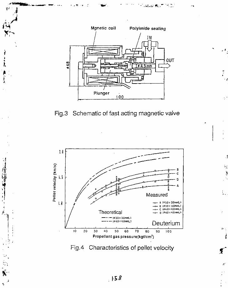
Mgnetic coil Polyimide sealing
IN
OUT
Fig.3 Schematic of fast acting magnetic valve
>> 1.5 -uo
0)
a A («30x 3.0mml>B 1*30 i 3.0tnmL)C (*<l0«1.0mnLl0 1*1.0 ' 4.0mrnL)
20 30 10 50 60 70 80 90 100
Propellant gas pressure(kgf/cm2)
Fig.4 Characteristics of pellet velocity

INJECTION LINE GUN ASSEMBLY
il
DIAGNOSTICSTATION No. 3
DIAGNOSTICSTATION No. 2
\ DIAGNOSTIC\ STATION No. 1
GUIDE TUBE \ M 1 C R 0 -WAVEN o 2 \ \ No.1 \ \ CAVITY
P H 0 T 0 D J 0 D E \ \ PHOTODWDE
TORUS INTERFACEVALVE
VACUUM EXHAUST SYSTEM
Fig.1 Schematic of pellet injector
Drivingmechanism
.el let/ X corner
/HolderHolder bellow
HeolerLHe heot exchanger
Fig.2 Schematic of gun assembly

- J
>
1
$_,uc"a
o .O)c
Jell
u.
90
80
70
60
50
40
30
20
10
-
CD oCft±0
o C§g^g °°Vo °
o o °oo
Deuteriumi i i i i
1.4 i .5 1.8Pellet velocity(km/s)
Fig.5 Characteristics of pellet fueling efficiency
fft
I 6 c

1 8
^f "*> -' Recent Results on Pellet Physics and Technology for ITER in Technical University
B.V.Kuteev, S.M.Egorov, S.G.Kalmykov, V.G.Kapralov, K.V.Khlopenkov, I.V.Miroshnikov,M.A.Parshin, D.V.Polyakov, P.V.Reznichenko, V.Yu.Sergeev, M.L.Svoyskaya, I.V.Viniar.
JI ' Technical University Applied Physics Ltd, St.Petersburg, 195251, Russia
h Recent results dealing with pellet injector technology and studies of plasma pellet' 4 interaction we reviewed. ".
I. 1. IntroductionInterest in pellet injection technology for tokamak plasma fuelling and diagnostics has been
growing regularly during recent years. The main points of activity in this field correspond to thoseformulated in the ITER tasks description [1 ]. The tasks include - development of a reliablecontinuous pellet injector with moderate pellet velocity V 1-2 km/s;
- development of a high velocity injector with V > 5 km/s;- further improvement of pellet ablation model;- study of transport phenomena related to pellet injection;- development of plasma diagnoslics based on both hydrogen and impurity pellet injection.
Most of these problems are being developed at St.Petersburg Technical University. The purpose ofthis paper is to give an overview of recent results of the group related to ITER-tasks.
2. Pellet Injection TechnologyBoth hydrogen and impurity pellet injectors have been designed and fabricated for several
lokamaks. The parameters of the stands and injectors are presented in Table 1. The strategy of thefuelling pellet injection program was formulated together with Efremov Institute in [2 ]. This strategy
. ^ concentrates on developing a single stage light gas gun which operates in continuous mode and has,. a moderate pellet velocity.£!(, Two approaches to a continuous operation regime have been already developed. The first; ' • $ • one is based on two extruders which work in turn. The scheme of the ITER-stand which uses this{ • M l
t'Ji principle is shown in Fig. 1. The stand is capable of operating with pellets of 4 mm in size and with an>:\ injection frequency of up to 3 Hz. Pellet formation and acceleration are produced in two separate^T units joined by an intermediate barrel. This technical solution is similar to the one used in the T-15. f hydrogen pellet injector [3 ]. The stand operates in closed gas cycle mode. The hydrogen used for \ .' I pellet production and acceleration is utilized in a closed vacuum/gas system. The first experiments' with a single extruder have demonstrated acceptable cryogenic parameters. Extrusion of the'• hydrogen rod is under study now. This year we plan to start acceleration experiments as well as
j * beginning two extruder operation.'] Trying to simplify extrusion technology g3s and pulsed extrusion approaches have beenI developed. The schemes of the corresponding stands are shown in Fig.2. Successful gas extrusion of• I the hydrogen rod with a diameter of 2 mm h3S been obtained during 10 min. Dependencies of the »-•'. extrusion speed versus extruder temperature for several points of the gas pressure are shown in,, Fig.3. The extrusion speed obtained in gas approach is acceptable for using in the continuous pellet
i ' injectors. However, continuous high pressure in the extrusion system is not desirable especially in a. " tritium circuit. This difficulty could be overcome in a system with pulsed pressure created in liquid j * r '
hydrogen. Such a stand has already been assembled and we plan to obtain first results this year.

i l l
For plasma diagnostics using impurity injetlion the Diagnostic Pellet Injector (DPI) was
produced for T-15 and ASDE.X-Upgrads. The scheme of the DPI is shown in Fig.4. The parameters
of the injector presented in Table 2 allow to perform experiments directed on the diagnostics of
> magnetic fields, transport phenomena, and the study of ablation physics [4]. A dependence of the
•, pellet velocity on propellant pressure is show in Fig.5. In contemporary experiments almost all
plasma regions are available for the carbon pellets with that velocity range. In reactor case, such an
• injector can be used for diagnostics of boundary plasma.
l\
3. Apparatuses for cloud photography.
* .' A strong interest in magnetic field configuration in the tokamak requires the development of
I special equipment for fast photography of the clouds near ablating pellets. Two types of such devices
have been designed for these purposes to be used in ASDEX-Upgrade experiments. A high-speed
• . camera which uses film has been prepared for experiments. The camera allows one to obtain in one
lokamak shot up to 70 frames with exposure time greater lhan 2 / i s and has a remote control system
which allows up to five shots without reloading the film mechanism. Film images are processed using
an automatic rajcrodensiloineler. A typical scries of frames for one T-10 tokamak shot are shown in
Fig.6. The inclination angle of the cloud corresponding to the lilt angle of the magnetic field is
determined in automatically or manually.
Film developing and processing procedures are time consuming. A new CCD-camera
requires much less time for data acquisition and processing. The camera's characteristics a r ;
summarized in Table 3. This camera provides approximately the same possibilities in Ihe tilt angle
measurement as the high-speed film camera, but the data processing procedure requires only a few
seconds after each shot. The CCD-camera is planned to be manufactured this year.
4. Ablation model
A detailed analysis of the T-10 ablation data for hydrogen pellets has shown that the best
I agreement with the experimental dala base gives a scaling in !he form:
A K=(3.3 ± 0.9)107n'//3j5/3r4/3rn-l/3 | fpoi/s
i'j"4i" T h e coeff icient C = 3.3 w a s d e t e r m i n e d by fi l l ing t h e c a l c u l a t e d a n d m e a s u r e d p e n e t r a t i o n d e p t h for
•• .ji the experimentally measured profiles of clcclron density and temperature.
'&' A correlation factor hisiogram for the database is shown in Fig.7. The coefficient is approximately
yt equal to the one in Parks' formula \5) recommended by ITER-CDD and two limes less than Kutccv
x 1 et al. [6 ] formula predicts. A disagreement with the predictions of [6 ] may be overcome if the plasma
' j cloud near the pellet were taken into accouni. The optical thickness of the plasma cloud should be
, J then of the same order as the neutrals' one.
The so-called "lentil" model which describes a shape evolution during the ablation process of
initially spherical pellets has been devdop.-d [7J. The model assumes that curvature radii of iwo
'" ••'.)> pellet scmisphcres (from current and opposite sides) do not change their values dur ing abla i ion but
1 simply move toward each o ther thus de te rmin ing the lentil form of l he pellet. Fig.8 shows a
3 : correlation between exper imental ;ind calculated ablat ion curves for the carbon pellet injected into T -
' 10 tokamak. It can be seen thai the "lentil" approach of the ablat ion model leads to reasonable
• agreement.
, . ' ' 5. Radial transport studies
Perturbations of lhe plasma densily, temperature and the current created by pellets were
used for determination of the panicle and hcai diffusion coefficients [8 ]. Particle pinch velocity and

its influence on current density transport have been analyzed. For the diffusion coefficient D andpinch velocity V reversed task procedure has allowed the following scalings:
D(l5cm> - n e<"2-3 * 0-*>I p «-5 ± 0-?>
V(lJcm) - n e ' '2-1 * °'5)1 P(tX5 * °-5)
Comparison of the loop voltage after injection with simulation results taking into account temperatureperturbation have shown ihat possible pinch of the plasma current density with a velocity of 30-50cm/s in the middle zone is stimulated by a pellet [9]. These velocities are 3-5 times less than theV determined from reversed task procedure but are necessary for correct loop voltage simulation (seeFig.9).
It was observed that in the case of carbon injection, heat and density transport have differentcharacteristic limes and may be analyzed separately. In the hydrogen injection case, both densityand temperature evaluate with comparable times. Coupled transport of the density and heat forhydrogen injection makes the problem of determination of transport coefficients more complicated inthis case. Our analysis of the T-10 hydrogen data have shown a weak dependence of the effectiveheat conductivity on plasma parameters while for the carbon pellets we observed good correlationwith Ohmic scalings. This result is illustrated in Fig.10.
6. Longitudinal transport studiesPlasma expansion along the magnetic field determines installation of toroidally symmetric
density perturbation in the tokamak. A program simulating this process has been developed.Interferometer signals in the conditions corresponding to ITER layout [10] of the pellet injector andinterferometer is presented in Fig.l 1. The plasma expands in a toroidal direction with a velocity nextto ion sound velocity with unperturbed electron temperature. This fact was observed using SXRmeasurements on the T-10 [II] and was simulated for one dimensional plasma expansion inrcf. [12]. Typical time for relaxation of the interferometer signals is 1 ms, much less than radialtransport times (1 s) expected in ITER.
7. Magnetic field structure studiesHigh-speed photography of hydrogen clouds and toroidal deflection of carbon pellets were
used for determining of the safely factor profile in the T-10. It was show that using maximumintensity points of the hydrogen cloud image leads to simple and reliable determinations of thedirection of the magnetic field. Nevertheless, obvious scattering of experimental points for the tiltangle which exceeds the error bars of the method (Fig.12) has an undetermined nature. Bothinstabilities in the cloud and fluctuations in the current density might be responsible for the observedscattering of the angle.
Trajectory deflection measurements also indicate current density fluctuations. A significantpeculiarity was observed in the region near q = 3/2 magnetic flux surface [13]. This method haspermitted studying current density in a wide range of regimes in the T-10. Unfortunately, in largermachines with less current density and large size of the pellets, the deflection is expected to be toosmall for diagnostic purposes.
8. Conclusions
Research and experimentation in pellet injection technology and plasma diagnostics aresignificant at the Technical University. In the engineering area the main interest is in achieving acontinuous regime for which new approaches are developed. For plasma diagnostics new impurity

'-*•£ - tf-1 $5-. •
injectors and cloud framing systems are designed and manufactured. In the physical area the studiesof transport phenomena, magnetic field diagnostics and ablation physics are in progress.
References:l.D.Legeretal. ITER Fuel Cycle. ITER-FC-1.1-10.1990.2. B.V.Kuteeveial. Plasma Devices and Operation, (1992), vol.2, No.3.3. V.G.Kapralov et al. Abstracts 5th USSR Conf. on Eng. Probl. of Thermonucl. Reactors-CCNIlatominform., Moscow, 1990),p.292 (in Russian).4. B.V.Kuieev. in Diagnostics for Contemporary Fusion Experiments, ISPP-9, Varenna, 1991.5. P.Parks el al. Phys.Fluids. (1978). vol.21.1735.6. B.V.Kuieev et.al. SovJ.Plasma Phys. (1985). vol.t 1.409.7. S.M.Egorov et al. Nuclear Fusion, "(1992), vol.32, 2025.8. M.Svoiskaya et al. in High Temperature Plasma Diagnostics St.Peiersburg (May, 1993).9. S.G.Kalmykov el al.PismavJETP (to be published). "10. ITER Diagnostics. ITER Documentation Scries N'o.33, IAEA, Vienna, 1990.11. V.G.Kapralov et a!. Europhysics Conference Abstracts (Berlin) vol.!5C, pan 1, p.337,1991.12.1.Yu.Veselova etal. Pisma vJTP, (1993), vol.19. No. 7,75.13. V.Yu.Sergeev et al. Europhysics Conference Abstracts (Lisbon) 1993 (to be published).
Table 1. Parameters of Pellet Injectors and Stands
Stand/Injector
ITER-stand
Extrusion stand
Diagnostic PelletInjector
Place
Efremov
TechnicalUniversity
Kurchatov,IPP (Garching)
Main Characteristics
Vp = 1 km/s, dp = 4 mmRepetition rate 3 Hz, H,D
2 mm diameterHydrogen
Vp = 500m/s, dp =.5 mm
Table 2. Parameters of Diagnostic Pellet Injector (DPI)
Goals
long termoperation
continuousextrusion
diagnostics,magnetic field
pellet velocity Vp - up to 500 m/s; •pellet diameter dp - from 100 mkm up to 700 mkm;amount of pellets in the charger unit -90;amount of propellant gas penetrating to the tokamak chamber - less than 1 0 " part./shot;propellant gas - helium, hydrogen;spherical carbon pellets or other solid material pellets can be injected;injector dimensions - 800x500x300 mm
Table 3. Parameters of CCD-camera i
- information capacity: frames amount 50
frame dimensions, pixels 22x1024 ,..- survey rate, /is/frame 2-50- spatial resolution in plasma 0.4 mm- dynamic range of output signal 100-1000-duration of the whole data archi visa lion cycle, s 2-4 _^- maximum frequency of the detector data readout, MHz 1 .5!

* ->
7>t (chcfftc of iht utitd with iht JTEfl-Klf* paramcirn: I—curitdcr d i i « i ; I—fuelUquc'io. )—»in>4cra: *—h«il kt jn: i—i««rnwdiil* b*ff«1: *—He flow rcfuluor: 7—Ju|nDiiicth jmNr: I — ( » i cuiimi off mcchaninn: 9—irmn birrtl: 10—fin »»Ut; I I—wcuum pump:13— cortif»«ior; 13—opiKal probe: M—knife | J I C . O - i c W H mixer
Fig.l
v .
*i rti
(0 12 I1! T.K
Fig.3
Fig.2Fig.4
1
pr.rp or uKUOff rai.ns
oi
oD
P
O nooo
0 0 2S 0 SO.« 75.0 180.1) !,»,.«
Fig.5
10 11
Fig.6

taier tty;lpfr»:n l i :
Fig.7
Fig.9
a
si
a
• •
"• / I /
1
>
/Iim
i.S 1.75 1.1 1.2S
1l l f V /
I.I I.S I.S 1.15 I.I 1.2
12.3S 13.00 17.38 DJDD SJXI S.
X,trr
Fig.8
e
"V(1.0
o.«
0.2
» C.oil,
/
/ .
D, (
' ' "
8/
(I"0 0.2 0./, ~0.G 0.8 vT-n H ?
Fig. 10
(j, n.n
i
... .
I
'z
i
—
iiiif t.
.1:o io 20 r, cm
Safely "taclor profiles'
IISIMJ i\vo diffcicnl
Fig 11 Fig. 12
I 66

19
tt. .' -ters/i-ur.g lecr^iei" "n^v-Tr;?- : y ,
?•?, ?ol.iiechn.icheskaya, 5t.Petersburg, Russia
ngle, lour' and eight barrel injectors with in-situ tyj~
roducing have been developed to perform investigations
-Ji&, T-15 and OKI, tokamaks ecnsiquently. All K2 pellets
-rd simultarieously in the barrels and can be shot with
er'-'al-s I. s and more. Eeliuin gas under 110 bar presi-ur
];.- ;.;.T-e'J! t-:- aooelerate j^ellet?. Pellets veiosity from 300
Un i.v-r-- i-'-y
"llowir;g the laboratories of Fran/;^ V\\, ler uari: [2], It .ly
d etc. we try to master the "in-eiiu" techniques with
ent aprlication of tills- type injectors in both the real
-: experiment?.- and tritium injector creation. Uo-to-da^e
'Z n in this activitv a"* T'l' e 'te'l in t'ne f -l' ow pp'
F_Tver.!!T;er;CB aDi' .rHtus and results.
with f. aii-c cleo ^••.••ntitnctJc val-»- '' f u l l time ov/eratioi

t*
iMf n~?.r 1 rns ).
•' > ' The~main dimensions are shown on fig.1. Barrel diameter
and lenth are equal 1 .6 mm and 200 mm accordingly. The all-round
radiation shield is absent. Injector is installed vertically as it
' is needed on tokamak T-14. The mass of central heat exchanger is
* ':nly 100 g , so the initiation regime of co-oling from room
"' temperature to -5 Ii takes ^5 minutes. During H- condensation the
.A- • t-•::".;-erat'ore of heat exchanger does not change more than •"." 7".
jl After ?hot the temperature is increased from 5 X to 8,5-? ••". The
duration of the wiiO-le oyole of making and shooting a pe^Ie* i£-
less than 3 minutes. In normal operation helium conf-ump t ion
ir- "e£5 than 4 l''h.
Tiie main dimensions are shown on fig.2. Trie diameters of two
barrels are 1 mm, another ones are 1.4 mm. The lengthes are 160 mm
and 220 mm accordingly. The mass of central heat exchanger is 3 kg
so the shot from one barrel does not change the temperature of
another one. TWO barrels are continuous and. two ones "nave been
made with coo-per freezing cell between two pieces of barrel. V7e
have not seen any distinctions in pellet formation in different
barrels. The duration of initiation regime is nearly i hour. Trie
ir-.f'ec tio?. ey-Ie ''akes r- minutes. Tiie pellets lengthen are ?• -6 mm
^r)6 <"-\i-; be oharig -d by heaters from both sides of barrels. r,^£<:-re
-•':.-:•' ft- l:*-*.^•=••'. barrels '.ii oae-- i:>f shooting with 5~o ;TOT pallets.
Ih-? S!ien"--r ai*^ ]-i'er.et:ted i -n fig. 3- Four barrels fiav^ 1 mm
disi-rir-ter's and the c-ti es have 1.6 mm r-nes. "nlik*? t-iwlr-i;?
lrjectorp the hy-iro-gen for making pellets is admitted inside
barrels from both sides. In order to minimise helium consumption
the cooling is realised by helium flow being supplied along two
•?oa>:ial tubes. Injector is manufacturing now.
"In-situ" injectors developed at 5t.Petersburg Tecimicul
"niv-rsi'y can be used for the plasma diagnostic and investigation
in ^ ?m-tll tO'ka-.oaks a? a riirii'le and reliable tools riiike the
""r—'-'tive pell-^ inj-i'. tc-rs being created for the plasma suuoiyin.T
" '""'"""

*•' • M
i
1 -••!i-nci c-gy, Av 1 i~non ' ' ?8? ^.
[L] "-!.£•_• renfatn c t *»!. , Workshop on P e l l e t Iri.jeo tc^rs, KvHLA ,1PHS rai
f'1992>.
[33 A.?rattolillo et al., Workshop on Pellet Injectors, ENEA,
Frascati (1992).
'i; H.Kuteev et al., Plasma Levioes and Operations,London,1992,
v.2,No.3•

.1• / * -..•
Fig. 1. Singleshot Pellet Injector

•JH' W .
-•-^Lii/ <*;,."• '.SZ.:.
I i

M vifc*
; / f - \,..
x:
^ • j ' - ' A - ' ' • • ' A ' 1 ' ' - ' A ' * 1 C - - - 'A 3J
r • •
•TJ
' ' * • • /
. l' - .
1
" . • . ; , " • . 1:• j
1 1 i. 2. , " : ; ' . ,1 1 ::-;| i \l'.
i •-
i >
" j
».'J1 -
•3
O
' • • ; •
:£J

20
•I.
DEVELOPMENT OF INJECTION-ANGLE CONTROLLABLE SYSTEM OFICE PELLETS AND ITS APPLICATION TO THE JIPP T-IIU TOKAMAK
H. SAKAKITA, K. N. SATO, M. SAKAMOTO 1, R. LIANG, K. KAWAHATA,H. KITAGAWA, AND JIPP T-IIU GROUP
National Institute for Fusion Science, Chikusa, Nagoya 4 6 4 - 0 1 , Japan"•Research Institute for Applied Mechanics, Kyushu Univ., Kasuga 816 ,Japan
A new technique for an ice pellet injection system with controllability ofinjection angle has been developed and installed with the JIPP T-IIU tokamak inorder to vary deposition profile of ice pellets within a plasma. Injection angle canbe varied very easily and successfully during an interval of two plasma shots inthe course of an experiment, so that one can carry out various basic experimentsby varying the pellet deposition profile.
The injection angle has been varied poloidally from -6 to 6 degree by changingthe angle of the last stage drift tube. This situation makes possible for pellets toaim at about from r =-2a/3 to 2a/3 of the plasma.
From two dimensional observations by CCD cameras, details of the pelletablation structures with various injection angles have been studied, and a coupleof interesting phenomena has been found. A long helical tail of ablation light hasbeen observed in the case of an injection angle smaller than a certain value. Thedirection of helical rotation (tail) is independent to that of the magnetic field linesof the torus. It seems to rotate to the electron diamagnetic direction poloidally,and to the opposite to the plasma current direction toroidally. Consideration onvarious cross sections including charge exchange, ionization and elastic collisionsleads us to the conclusion that the tail-shaped phenomena may be the result ofplasma rotation with the condition of charge exchange equilibrium of hydrogenions and neutrals at high density regime.
Thus, the system of variable angle injection may become a useful diagnostic toolfor the plasma rotation measurement.
1. INTRODUCTION
Recently using the ice pellet injection,various investigations concerning theparticle transport, the thermal transportand the pellet ablation within the torusplasma have been done in many plasmaexperiments. Especially in the JIPP T-
IIU tokamak, several results concerningfundamental properties of plasmas areobtained and reported (ref.l, ref. 2). Inorder to study fundamental phenomena,the degree of freedom concerning thepellet injection becomes an importantfactor. For example, the pellet-sizecontinuously controllable injection, theinjection-angle controllable system, the

high repetiiion injection and continuousinjection, and so on.
In the present study, we havedesigned and constructed a new system,by which the injection angle of an icepellet can be easily controlled shot byshot, not moving the whole injector.Moreover the ice pellet injection systemwith the injection-angle controllabilityhas been installed to the JIPP T-IIUtokamak in order to control thedeposition profile within the OH plasma.Therefore, one can carry out variousbasic experiments by changing thepellet deposition profile drastically andactively.
Details of the pellet ablationcharacteristics with various injectionangles have been studied from twodimensional observations by, CCDcameras.
Then we have obtained a couple ofinteresting phenomena concerning theflow of ablation cloud, where the chargeexchange equilibrium of hydrogen ionsand neutrals may exist at a high densityregime. An information about plasmarotation may be derived from thoseresults.
2. EXPERIMENTAL FACILITIES
Figure 1 shows an injection-anglecontrollable system with a cross-sectional view of the JIPP T-IIU. Theinjection angle has been variedpoloidally from -6 to 6 degrees bychanging the angle of the last stage drifttube, whose injection angle is limited bythe port structure of the device. Thissituation makes possible for pellets toaim at about from z =-2a/3 to 2a/3 ofthe plasma, here the symbol "a"designates the plasma minor radius.
Lijecaon • ' • * '• -\
By swinging this guide tube, we can changepellet injection angle easily snot by snot.
Pell-
Vacuum Puatpir g System
Fig. 1 Poloidal cross-section view of aninjection-angle controllable system thatinstalled in the JIPP T-IIU tokamak
Two CCD cameras have been installedto obtain two dimensional views of anablation cloud. One is put on a horizontalport to see the cloud tangentially, andanother is put on an upper port toobserve the toroidal movement of thecloud. The setup for tangential view isshown in Fig. 2. Although no opticalfilter has been set in front of the CCDcamera, it can be confirmed from otherH« diagnostics that the main light to CCDcamera should be almost Ha light. Thepicture taken by the CCD camera showstime integrated lights emitted from theablation cloud, because the exposuretime is 32 msec. (The typical time thatan ice pellet passes through a JIPP T-IIUplasma is shorter than about 1 msec.)
CCD Ctfcerz
essel
Fig. 2 Top view of the CCD earner;system that installed in the JIPP T-IRtokamak

x->
4
"'1
3. EXPERIMENTAL RESULTSDISCUSSION
AND
Figure 3 shows a case that an ice pelletis injected at the position of aboutZ =12.0 cm, here the direction of toroidalmagnetic field (Bj) is counterclockwise,and the direction of plasma current isclockwise. Figures 3 (a) and (b) arephotographs of the tangential view, andof the top view, respectively. (After this,figures (a) and (b) represent the samesituation as above.) As expected, we cansee that the ablation cloud has a tracebeing straight along the pellet path. (Wecall this phenomenon as "straightmode".)
(a)
Figure 4 shows a case that an icepellet is injected at the position of aboutZ =7.0 cm. here B T direction iscounterclockwise, and Ip direction isclockwise. As Figs. 4 (a) and (b) indicate,the ablation cloud which consists ofneutral hydrogen essentially flows bothto poloidal and to toroidal directions.From these two results, a long helical tailof ablation light flows independently onthe magnetic field lines of the torus. Itrather rotates to the electrondiamagnetic direction poloidally, and tothe opposite to the plasma currentdirection toroidally. (We call this case as"tail mode".)
(a)
Pellet
Canter
Center
IPellet10 cm
10 cm
Edse Cimer Edge
Csr.ie: Edge0
r[cm]23 Fig. 4 Photographs taken by the CCD
camera, (a) is a tangential view and (b)Fig. 3 Photographs taken by the CCD i s a t0P v iew> BT= ccw, Ip= cwcamera, (a) is a tangential view and (b)is a top view, BT= CCW, Ip= cw

Figure 5 shows a case that an ice pelletis injected ai the position of aboutZ =S.O cm. However, in contrast to thecase in Fig. 4. the plasma currentdirection has been inverted, that is thedirection of counterclockwise. Theablation cloud flows to essentially thesame direction as that of Fig. 4, but dueto the change of the Ip direction, thetoroidal flow direction becomes opposite.
(a)
Pellet
10 cm
Fig. 5 Photographs taken by the CCDcamera. >a) is a tangential view and (b)is a top view, B T = CCW, Ip= ccw
Also, the experiments have beencarried out for conditions with othercombination of B T and Ip directions; inother words. ( B T . Ip) = (cw, cw) and (cw,ccw). Then, the ablation cloud rotates tothe electron diamasnetic direction
poloidally, and to the opposite to thepiasma current direction toroidally,which is same as Figs. 4 and 5.
4. THEORETICAL CONSIDERATION
Here, we will consider about the tailstructure. In our pellet injectionexperiment, the number of hydrogenatoms within the ablation cloud may bearound 3 x 1 0 * 9 p a r t i c l e s . Thepenetration depth 'D' is supposed to beabout half plasma radius, namely,1 0 . 0 - 2 0 . 0 cm. If we consider acylindrical tube like in Fig. 6, the volumeof this tube is DxWxL = ( 3 0 ~ 1 0 0 ) x L .(Here, "VV" means a width of the cloud invertical direction.)
Pellet
Fig. 6 Theablation cloud
schematic view of the
By taking the measurement of otherpel let inject ion experiments intoconsideration, the temperature of theablation cloud is assumed to be 1 eV,and the velocity of the neutral particle iscalculated to be about 10^ c m / s .

Especia.'iy. ir the iengih 'L is assumed tobe 100 cm. dividing L by the neutralcloud velocity, the characteristic time ofthe flow becomes 100 Lisec. and neutralcloud density is around (0.?~ 1.0)x 1 0 16particles/cm-.
When the velocity of plasma rotation isassumed to be about 10 km/s, thecharacteristic time of the rotation, forthe flow length L of 100 cm will becomearound 100 usec.
From these considerations, we may saythat the neutral cloud flows along withthe movement of plasma rotation at thesame time scale each other. In this casethe momentum of neutral cloud may betransferred from the momentum ofhydrogen ions.
Consideration on various cross seciionsincluding charge exchange, ionizationand elastic collisions leads us to thefollowing conclusion. When thehydrogen ion energy is l.O-lCP eV,cross sections both for elastic scatteringand charge exchange are the same orderwith each other (ref. 3i. And themaxwellian rate coefficient for chargeexchange is larger than that tor electronionization over wide energy region (ref.
Thus, i' seems reasonable to concludethat this phenomenon may be caused bythe condition oi charge exchangeequilibrium of hydrogen ions andneutrals at high density regime, and bythe toroidal and poloida! rotation of aplasma.
5. SUMMARY
A flexible injection-angle controllablesystem has been constructed, andinjection-angle controllability of the
pellet into the plasma has been realized.W7e can easily change the injection angle(ablation profile) shot by shot, notmoving the whole injector.
By using this system, the ablationcharacteristic has been studied, and wehave succeeded to observe interestingphenomena as follows for the first time.The ablation cloud from a pellet spreadsinto the plasma with the rotation to bothtoroidal and poloidal directions, notflowing parallel to the magnetic fieldlines of the torus, within a certaininjection angle (z < 10.0 cm). Thus due tofour sets of experimental conditions withthe plasma current and with the toroidalmagnetic field both of normal andinverse directions, we see that theablation cloud rotates to the electrondiamagnetic direction poloidally, and theinverse direction to the plasma currenttoroidally.
It seems reasonable to conclude thatthis phenomenon is caused by rhecondit ion of charge exchangeequilibrium of hydrogen ions andneutrals at high density regime, and bythe toroidal and poloidal rotation of aplasma. So the inject ion-anglecontrollable system might become auseful diagnostic tool for the plasmarotation measurement.
In order to make this phenomenonclear further more, various studies seemto be done, for example, measurementsof high time resolution of Ha. Hp, HyandHo lights, local parameter measurementslike density and temperature of theneutral gas, electrons and ions in theablation region. In addition, experimentswith NBI heated plasma and RF heatedplasma may also be interesting issues.

REFERENCES
1. K. Kawahata, et al., IAEA Nice Conf.,IAEA-CN-50/A-V-3-1, (1988) 2872. M. Sakamoto, et al., Plasma Phys. Cont.Fusion, 33(1991) 5833. NIFS, Data Book for the Cross Sectionof the Atomic Process: IPPJ-DT-48,
No. 1,(1975)4. R. L. Freeman, et al., UKAEA ResearchGroup Report, (1974)

21Development of Advanced Railgun for Injection of
\ Hypervelocity Hydrogen Pellets into Tokamak
K. Kim. J. Zhang, T. L. King, D. M. Windham, Jr. and L. S. BoltFusior. Technology and Charged Particle Research Laboratory,
i Depanment of Electrical and Computer Engineering,, . University of Illinois at Urbana-Champaign, Urbana, Illinois 61801, USA
• Advanced electromagnetic railguns at the University of Illinois that are specifically developed for- • injection of hypervelocity hydrogen pellets into a tokamak are described. Perforated side walls and
transaugmentatio:; schemes have been tested in an effort to improve the railgun performance. Theprincipal diagnostics are the magnetic probes, laser interferometry, optical emission spectroscopy,and a streak camera which are designed to determine the plasma arc length, the electron densitydistribution along the length of the arc, the line-averaged plasma density and temperature, and thepellet velocity change during acceleration, respectively. Using a prototype system hydrogen pelletvelocities as high as 3.3 km/s have been achieved on a 2-m-long railgun for a cylindrical pellet of3.2-mm diameter and 6-rara length. This report contains a brief overview of the University ofIllinois railgun program, the results to date, and the future plan.
I. INTRODUCTION
Since its inception in 1984, the railgun research program at the University of Illinois at Urbana-Champaign (UIUC) has been dedicated to the task of evaluating and demonstrating the feasibilityof applying the railgun principle to high-velocity hydrogen pellet injection for magnetic fusionreactor refueling [1-10]. The main components and distinctive features of the UIUC railgunsystem are described in this report along with the program's chronology and major achievements.'Die report also reviews work in progress and future plans.
' II. HYDROGEN-PELLET-INJECTOR RAILGUN AT UIUCJ.$. A schematic of the UIUC hydrogen-pellet-injector railgun system, which is a two-stage• ? , accelerator, is shown in Fig. 1. The first stage is a preaccelerator combining a hydrogen pellet
; generator with a gas gun. Liquid helium is used in the pellet generator to liquefy and freeze? ultrahigh-purity hydrogen gas into a cylindrical pellet at temperatures in the range of 4.5 to 6 K.} This hydrogen pellet is then accelerated to a medium speed (- 1 km/s) using a high-pressure light
gas (either hydrogen or helium) and injected into the second-stage railgun via a coupling piece.The coupling piece is perforated, and serves two important functions: to facilitate guided,continuous pellet motion between the gas gun and the railgun and to vent out the propellant gas
, coming from the gas gun so that the pressure inside the raiTgun bore may be controlled to a levelthat will suppress spurious arcing.
. Once the hydrogen pellet enters the railgun, a unique arc-initiating tungsten needle installed at the•1 gun breech is activated so that the propellant gas immediately behind the pellet (which has followed, the pellet from the gas gun into the railgun) may be electrically broken down, forming a plasma-arcj armature and therefore a conducting path between the rails. At the peak of this electrical
breakdown the main rail current is pulsed into the rail. While this current is flowing, the plasmaarmature becomes more fully ionized due to ohmic heating, and the resulting J x B force propelsthe pellet to a high velocity. The fact that no "conventional" fuse is employed to run this railgun
; . (i.e., it does not rely on the usual metallic fuse to effect the railgun operation) is important since' , high-Z impurities introduced into the fusion plasma during pellet fueling will contribute to lowering• " of the plasma temperature, which is undesirable.

" - < - • ? . . . 'SSL~.~
B B-dm ProbeD Light DoectorL Laser Bum
Nitrogen LaserPumped
Dye Laser KanopulserLight Source
Fig. 1. Schematic of the University of Illinois two-stage-railgunhydrogen pellet acceleration system
i
The diagnostics employed are mainly to determine the pellet velocities at the breech and muzzleof the railgun, to measure the various current and voltage components, to probe the plasma-arcbehavior and characteristics inside the gun bore, and to record the picture of the pellet entering andexiting the gun. Two pairs of laser-photodetector combinations installed on the coupling piecemeasure the pellet velocity and, with a predetermined time delay, trigger the arc-initiation circuit sothat plasma arc will form behind and not in front of the pellet. B-dot probes installed along thelength of the railgun measure the plasma-armature currents at different locations. A streak camerawith a field of view covering the entire gun length records the distance-vs.-time signature of theplasma motion inside the gun bore. This is possible by using a Lexan sidewall which issemitransparent to the plasma luminescence. By using a combination of a nanolamp with a 10-nsec light pulse and a camera, a still picture of the pellet exiting the railgun is recorded. Thispicture allows one to determine the amount of pellet erosion during acceleration. By using adetection mechanism similar to that on the coupling piece the pellet velocity is also measured justoutside the gun muzzle. The pellet finally impinges upon an impact transducer so that themomentum carried by it can be determined.
Probing of the internal conditions of the plasma-arc armature is achieved by using a Mach-Zehnder interferometer combined with a streak camera which measures the line-averaged plasmadensities along the length of the arc, and by using an optical multichannel analyzer system whichspectroscopically determines the change in the density and temperature of the plasma arc while ittravels along the length of the railgun. This information plus the information on the current andvoltage and pellet velocity and erosion is valuable in evaluating the gun performance andestablishing a theoretical model that can correctly describe plasma-arc-driven pellet acceleration.
III. HIGHLIGHTS OF RESULTS FROM UIUC RAILGUNS
The UIUC hypervelocity hydrogen pellet railgun program has been a pioneering project since itsinception in 1984. As a result, the research activities at the beginning centered around resolvingtwo major issues: (1) can a railgun with a small circular-bore (-1.5 mmD) and reasonable length
to \8c

r A
*""*»(~1 m) be built and operated to accelerate a projectile, and (2) can such a railgun accelerate a frozenhydrogen pellet without melting the pellet completely due to arc heating. In addition, a clevermechanism had to be developed to make sure that the use of a metallic fuse could be avoided sinceir would introduce high-Z impurities into the tokamak, subsequently quenching the plasma.
\ Since then, the program has steadily identified a number of critical technical problems unique toi the acceleration of frozen hydrogen pellets in a railgun and successfully developed practical1 engineering solutions to the problems. These problems are associated, in one way or another, withj the operation of the railgun in a vacuum and with the use of a cryogenic projectile which has" extremely low mechanical strength. Some of the major problems and their solutions arei . summarized as follows:* . fa; The problem of initiating a plasma arc in a debris-free manner: solved by the innovativejj deve lopment of fuseless technique for the initiation of the p lasma arc.* (b) The problem of coupling a pneumatic gun preaccelerator with the railgun in a manner
which provides control over the pressure distribution inside the highly evacuated (10°Torr) railgun to prevent spurious arcing: the solution involves the invention of aventilated coupling piece.
tc) The problem of operating an extremely small-bore railgun with a large length-to-diameter(L/D) ratio,
(d i The problem of obtaining sufficient mechanical strength and compactness in the hydrogenpellet produced by the pellet generator.
(•<.'.) The problem of diagnosing the size and shape of the cryogenic pellet before and after theplasma acceleration, etc.
I laving solved these problems of an operational nature and demonstrated the practicality of usingthe railiiun to accelerate cryogenic pellets to high velocities (~3.3 km/s) without a sabot (see Table 1and Figs. 2 - 4 for the velocity records and railgun parameters), we are now turning our attentionto the principal task of exploring the velocity potential of the railgun for refueling fusion plasmas.We have conducted many experiments and accumulated a significant database using 1.2- and 2-m-long, 3.2-mm-diameter railguns from which we have been able to develop a working picture of theiniL-riur ballistics occurring in our railgun. Our experimental data show that the occurrence ofablation and the resulting inertial and viscous drag from the ablation products is a major inhibitor to
, 5 the attainment of velocities significantly higher than 3 km/s. However, if ablation can bejj drastically reduced, velocities in excess of 10 km/s should be quite possible as clearly shown by
our recent free-arc experiments in which a free-arc velocity of 36 km/s was obtained.
This high free-arc velocity was achieved using a low-ablation sidewall fabricated out of mullitc,and is certainly a substantial improvement over the previous record of 10 km/s obtained with aLexan sidewall. The high velocity is also a direct demonstration that the inertial and viscous dragwhich is enhanced by wall ablation is the major inhibitor to the attainment of high velocities. Inaddition to the* new record free-arc velocity, our recent research achievements include thefallowing:
i:i) Transaugmentation rails that boost the magnetic field strength inside the railgun have beendesigned, fabricated, and partially tested producing encouraging results (see Fig. 4).Further detailed experimentation is required, and will be undertaken.
(b) Pulse-shaping networks that provide lower current to the main rail and higher current tothe transaugmentation rail, respectively, have been fabricated, installed, and successfullytested,
to A new hydrogen pellet generator-gas gun combination that allows one to fabricate frozenhydrogen (and isotope) pellets of variable diameters and lengths has been designed.constructed, and successfully tested. This hydrogen pellet generator not only improvesthe strength of the frozen hydrogen pellets produced, but it also substantially reduces theliquid helium consumption.

Xr- •
4
TABLEIHIGHEST VELOCITIES FOR VARIOUS RAILGUNS
Railgun Lengtn
Pellet Diameter
InitialPellel Length
P(psi)
V(kV)
l(kA)
vjm/s)
av (nvs)
»((«)
a(nus ?
L(cm)
1.2 m
1.5 mm
2 2 mm
360
2.00
3.20
941
1.71 *
770
800
9.66X10*
102
1.2m
3.2 mm
6 mm
600
4.50
-.3.50
1006
2.56 b
1554
420
3.70 X 10 «
75
2.0 m
3.2 mm
6 mm
1100
7.00
16.45
1227
3.30 •
2073
800
259 x 10 '
181
a. without transaugmantationb. with transaugmantation
2.3
2.2
2.1
2.0
1.6
1.8
1.7
1.6
I
i
A
A
;
I
AA
A
J
s e 7 s a i o 11 12
l'l (X10* A*.)
Fig. 2. Hydrogen pellet velocities on a 1.2-m railgun without transaugmentationsince September 1992
(d) In an effort to vent out the ablation debris and neutral particles from the railgun (so thatinertial and viscous drag will be minimized), a new railgun with a perforated sidewall hasbeen designed, built and tested. The preliminary results indicate that hydrogen pelletacceleration continuously increases with increasing rail current, and th?.t the manner inwhich the hydrogen pellet velocity increases appears more promising with tue perforatedrailgun than with the nonperforated railgun at higher currents. Further experimentation isrequired, and will be done.
I '

* 4
9
S. 2.5
AA
A
A
A
A
* A
A
* A
A
*
A
* , _
20 2S
l:l («10* **m)
Fig. 3. Hydrogen pellet velocities on a 2-m railgun without transaugmentationsince September 1992
2.6
2.4
2.2
2.0
i .a
1.6
1.4
1.2
1.0
Augmentat ionCurrant
O CA 1
* 1O 1
* a
o+
to
kA
.OS kA
1.8 kA
6.5 kA
1.2 kA X
%Xoo
*
8
j
- ik
s fo
^+0
0+
o
:
o
l't (»10* A1!)
Fig. 4. Hydrogen pellet velocities on a 1.2-m railgun with transaugmentationsince September 1992
(e) By combining a laser interferometer with a streak camera, detailed density profiles of theplasma arc armatures along the gun axis have been measured for the first time underdifferent operating conditions. These data indicate that at high voltages (or currents) thedensity profiles are no longer smooth but choppy and irregular, possibly indicating thepresence of an increasing amount of ablation. We hope that these measurements willeventually help us to understand and eliminate the factors giving rise to secondary arcs,which are an energy loss mechanism detrimental to efficient railgun operation.
(f) By measuring Stark broadening and line emission intensities at different time intervalsduring the railgun operation, we have been able to determine the change in the densityand temperature of a free arc as it travels toward the gun muzzle under a variety of
1*3

J
operating conditions. This and other similar studies will allow us to more thoroughlyunderstand and improve the railgun behavior.
(g) Numerous pellet acceleration runs have been performed with both room-temperaturepellets and frozen hydrogen pellets with an advanced railgun of 1.2-m length (whichcombines low-ablation sidewalls and transaugmentation rails), demonstrating that theadvanced railgun outperforms the old guns by a substantial margin. Furtherexperimentation is still needed on the 1.2-m gun, and advanced railgun concepts must beapplied to the 2-m gun to maximize the attainable hydrogen pellet velocities.
IV. CONCLUDING REMARKS
A fuseless, small-bore, two-stage railgun system particularly suited to accelerating frozenhydrogen pellets for fueling magnetically confined plasmas was described. Results were presentedon hydrogen pellet acceleration indicating that it is feasible to employ a railgun to acceleratehydrogen pellets to high velocities; however, to achieve the highest hydrogen pellet velocity, onemust reduce gun wall ablation (to minimize inertial and viscous drag) and deterioration of pelletintegrity. Capitalizing upon the achievements we have made so far, our next step in thecontinuation of this program is the development of some very innovative technologies to overcomeablation, with a goal of achieving velocities exceeding 5 km/s in the short term, and laying theinundation for even higher pellet injection velocities (exceeding 10 km/s) in the longer term.
This work was supported by the United States Department of Energy under Grant No. DE-K;02-84ER52111.
REFERENCES
11 ] K. Kim and J. Honig, "Application of railgun principle to high-velocity hydrogen pelletinjection for magnetic fusion reactor refueling," Fusion Tech., vol. 6, p. 372, September1984.
[21 J. Honig and K. Kim, "Pellet acceleration study with a railgun for magnetic fusion reactorrefueling," J. Vac. Sci. Teclznol., A 2, p. 641, 1984.
j .i | J. Honig, K. Kim, and S. W. Wedge, "Hydrogen pellet acceleration with a two-stage systemconsisting of a cas gun and a fuseless electromagnetic railgun," J. Vac. Sci. Technol., A 4,p. 1106, 1986."
[4J K. Kim, J. Honig, S. W. Wedge, M. B. Tanquary, W. H. Choe, A. Marzougui, and RobertY. Z. Bai, "Two-stage fuseless plasma-arc-driven railgun for injection of high-speed fuelpellets into tokamak," / . Vac. Sci. Technol., A 5, p. 2211, 1987.
15] K. Kim, "Electromagnetic railgun hydrogen pellet injector - progress and prospect," Proc.IAEA Technical Committee Meeting on Pellet Injection and Toroidal Confinement, Gut Ising,Upper Bavaria, Fed. Rep. of Germany, October 1988.
161 K. Kim and J. Zhang, "Investigation of the behavior of a plasma-arc armature inside a two-stage railgun and methods for preventing arcing," J. Vac. Sci. Technol., A 7, p. 955, 1989.
171 K. Kim, J. Zhang, T. L. King, R. G. Haywood, W. C. Manns, and F. Venneri, "Resultsfrom recent hydrogen pellet acceleration studies with a 2-m railgun," Proceedings of the 13thSymposium on Fusion Engineering, Knoxville, Tennessee, October 1989.
|S| K. Kim, J. Zhang, T. L. King, W. C. Manns, and R. G. Haywood, "Development of afuseless small-bore railgun for injection of high-speed hydrogen pellets into magneticallyconfined plasmas," IEEE Trans. Magn., 29, p. 435, 1993.
{<•>] T. L. King, J. Zhang, R. G. Haywood, W. C. Manns, and K. Kim, "Controls anddiagnostics on a fuseless railgun for solid hydrogen pellet acceleration," IEEE Trans. Magn.,29, p. 1186, 1993.
f 10] J. Zhang, K. Kim , and T. L. King, "Study of a new railgun configuration with perforatedsidewalls," IEEE Trans. Magn., 29, p. 534, 1993.
" * • • * " •

Iw... •*-.-.•
tt> 1
i4
K
DE"-T-O?MEN'T OF RAXLG'JKPELLET INJECTOR USINGA ULSiR-INC-CEtf FLASMA AfWAT'JSE
IAEA Technical ConaitteeMeeting on Pellet InjectionNaka. Japan. Kay 10-12. 1993
22
DEVELOPMENT OF RAILGUNPELLET INJECTOR USING
A LASER-INDUCED PLASMA ARMATURE
M. ON'OZUKA3, Y. QDA3, K. AZUMA5, H. OGINO3,S. KASAr. and K. HASEGAffAb
Mitsubishi Heavy Industries, Ltd., Advanced Nuclear Systems Engineering Department, 2-4-1,Shibakoen, Minato-ku, Tokyo, 105, JAPANbJapan Atomic Energy Research Institute, Tokai-mura, Naka-gun, 319-11, JAPAN
Electromagnetic railgun pellet injector has been investigated, aiming at high-speedpellet injection for fusion plasmas. A pellet pre-acceleration technique is used in orderto reduce rail erosion. The plasma armature is induced by a pulse laser beam. This uniquefeature reduces the supplied voltage to the rails, in order to avoid unnecessary breakdownbetween the rails and to reduce rail erosion. The power supply for our system employsPulse-Forming-Netwqrks, which provides a rapid current-rise to the rails and control ofthe current-hold time, thereby enhancing acceleration efficiency. The ignited plasmaarzature is accelerated by an electromagnetic force, that accelerates the pellet to highvelocity. A series of experiments using dummy pellets have been conducted to examine thesystem. In addition, the hydrogen pellet acceleration tests have been initiated. Thecurrent experimental results indicate that the railgun system can be one of the optimalmethods to provide higher speed pellets for fusion plasmas.
i
1. INTRODUCTIONRecent magnetically confined fusion
expericents have demonstrated better plasmaconfinement using a pellet injection tech-nique for fueling particles- into plasma.This fueling technique provides high-speedinjections of solid hydrogen-isotopepeliets into the plasma, which allows highplassa density inside the core plasma andactive control of the density profile, aswell as plasma confinement.
One of the main requirements for thepellet injector is to provide higherpellet-injection velocity .for the deeppenetration of pellets into lai er volumeand higher temperature of the plasma. Avariety of high-speed pellet injectionsystems have been demonstrated. These sys-tems include single-stage pneumatic injec-tors [lj, tF tage pneumatic injectors [2-5], electruj eam-heated rocket acceler-ators [6], an' electromagnetic railguns [7-11:. Current maximum velocity of thepellets up to 4kiE/'sec by the two-stage
pneumatic injector with a sabot (protectorof th: pellet), and 3.4km/sec without asabot The main limitation for achievinghigh pellet velocity is the strength of thesolid hydrogen-isotope pellets.The application of the electromagnetic
railgun system for pellet injection is oneof the most feasible technologies foraccelerating a brittle, solid hydrogen-isotope pellet to a high speed (up to5km/sec or over) without a sabot [7-11].Using this method, an armature, a movingconductor formed behind a pellet, isaccelerated gradually by the electro-magnetic (Lorentz) force along the railswith the desired pellet acceleration rate,wi.ich is kept within the allowable force soas not destroy the pellets. Then thearmature accelerates the peilet to highvelocity. This type of system has alsobeen investigated by Kim's group ?tUniversity Illinois, which has achievedhydrogen pellet acceleration up to 2.82km/sec [10].
Mitsubishi fleavy Industries, Ltd. has

' * - •
DEVELOPMENT C- RAILCUNPELLET :N_*ECTOH US:NCA LASES-INS-CED FLASM7. JVR-.A77SE
-Mitaubichi 3eavy Industries,—ttd—has-been investigating the application of therailgun system for rhe pellet injector incollaboration with Japan Atomic Energy'Research Institute [7-8]. The objective ofour research is to establish a railgunsystem that can achieve a 5km/sec speed-class pellet injection for fusion plasmas.
2. MAIN FEATURES OF RAILGUN SYSTEM2- 1 Pellet Pre-acceleration Technique
Within railgun application systems, thepeliet injector is considered to be a newapplication. Since the projectile (pellet)is light (in the order of Eg), the requiredelectric current for the pellet accelera-tion should be comparatively small.Generally, conventional railgun systems,developed for research on condensed mattersunder high pressure and on hypervelocity-i.-pact simulation of Eeteoroi'ds striking aplanet, use a high electrical current ofhundreds of kA supplied from a largecapacitor bank to the armature for a shorttime period to accelerate a projectile (inthe order of g), and achieve a highvelocity of 7.4km/sec or more [12-13]. Inaddition, conventional systems use a metalarnature, which initially requires highelectric energy to breakdown. However, inthese conventional systems, the damage tothe rails, caused by the initial formationof the armature and ablation from thearmature, is significant. Therefore, therail materials can be used only a fewtiEes. Jn order to solve this problem, ourrailgun system employs a pellet pre-acceleration technique, which reduces thecurrent passing time through the plasmaarcature between the rails. Using thismethod, a pellet is accelerated initiallyup to lkn^sec by a pneumatic injector.Furthermore, light gas is used as thematerial for the plasma armature in orderto reduce the electric energy required forthe plasma formation.
2.2 Laser-induced Plasma Armature TechniqueIn the railgun system, the armature must
be induced behind the pellet. A metalarmature is usually used in the convention-al railgun systems. However, it cannot be
Meeting on Pellet InjectionNaka. Japan. Kay 10-1*. 1593
used for the pellet injector because of theimpurity restriction. Since the pellet isinitially accelerated by the pneumaticmethod, the propellant gas can be ionisedto form a plasma armature. A tungstenneedle or a spark-plug is usually installedto induce the plasma armature. However, itis necessary for the propellant gaspressure to be adjusted to the preferablecondition for the propellant gas tobreakdown. Since the ionization bybreakdown forms a limited number of ionizedparticles under reduced pressure, a highsupplied current must be applied to therails in order to maintain the plasmaarmature between the rails. In addition,unnecessary breakdown is sometimes causedbetween the rails under reduced pressure.Our system employs a pulse laser beam.
Using this method, ionization of thepropellant gas is initiated optically by anintense laser beam. This method has thefollowing merits:(1) Reduction of the supplied voltage to
the rails, in order to avoid unnec-essary breakdown between the railsand to reduce rail erosion.
(2) Production of a good electricallyconductive plasma armature toprovide a rapid initial currentresponse through the plasma arma-ture.
(3) Production of plasma armature underhigh pressure gas to provide highpre-acceleration pellet speed and toavoid unnecessary breakdown betweenthe rails.
2. 3 Pulse-Forming-Networks Power SupplyIn order to control the pellet accelera-
tion rate at the desired value, our railgunsystem employs a Pulse-Forming-Networks(PFN) for the power supply. The PFX powersupply provides a rapid current-rise to therails and control of the current-hold time,thereby enhancing acceleration efficiency.
3. EXPERIMENTAL DEVICEA schematic diagram of the cu:rent
railgun system and a cross-section of therailgun are shown in Figures 1 and 2,respectively. The specifications of thesystem are summarized in Table I. The

M
I
DEVELOPMENT OF RAXLCUNPELLET INJECTOR USINGA LASER-INDULED PLASMA ARMATURE
system consists of a pneumatic pre-acceler-ator for the first acceleration stage anda railgun for the second accelerationstage. The railgun is installed in thevacuum chamber under pressure of less thanlOOPa. The pulse laser beam is introducedthrough the insulator between the rails andfocused approximately at the center of therails. The pre-accelerator is composed ofa gun barrel with a cooling block, a fastopening valve, and a coupling piece. Ahydrogen-isotope gas is supplied to the gunbarrel, which is partially cooled at thecooling block by liquid-helium. Thus, ahydrogen-isotope pellet is formed insidethe barrel. After the pellet is formed,the helium propellant gas is supplied tothe pellet by the fast opening valve toaccelerate the pellet through the barrel.The pre-accelerated pellet then enters thebore of the rails. A Q-switched YAG laseris triggered to induce the plasma armaturejust behind the pellet, forming a conduct-ing path between the rails. Electric poweris supplied from a Pulse-Forming-Networks(PFN) to the rails to accelerate the plasmaarmature, that then accelerates the pellet.
First Stag* (Pn«umatlc Ptlltl Aceslcotor)
V»cuum ii *ll Coupling
£* rfcflfe
S«concf Sttga (FMIgun Acctlertlor)
OSO>Dogltni•rJg Siorag* Okcllloscapt
1 1 1 1Po»er Supply 2
Helium Hydrogen GunPrcp*l!iftl Full BCBS CM
Figure 1 Schematic Diagram of RailgunSystem
Focusing Lens
LaserBeam
IAEA Technical CousitteeMeeting on Pellet InjectionN«k«. Japan. Ma; 10-12. 1993
Table I Specifications of RailgunType: Laser-Prearc RailsunRailgnn: Bore Diameter: 3nm
Acceleration Length: IraMaterials; Cu or W-Alloy
Hydrogen Pellet:Diameter: 3nanLength: 4-7nmMaterials Solid-Hydrogen
Dummy Pellet: Diameter: 3mmLength: 3~6mmMaterials: Poly-Carbonate,Lauan, Balsa
Propellant Gas: Material: FeliumPressure: up to 4MPa
Laser Beaa; lype: Pulsed YAG LaserPulse Energy. 900mJ tor 6nsWavelength: 1064nm
Power Supply: Type: Pulse-Forming-NetworksCapacitors: 23.5mFx4Charging Voltage: - 350VSupplied Current: - 25kA
4. EXPERIMENTAL RESULTS4.1 PFN Power SupplyThe newly built PFN power supply has been
tested. Four capacitors are connected inparallel to provide a rapid current-rise tothe rails and control of current-hold time,aiming at higher acceleration efficiency.Figure 3 shows the supplied currentprofiles using one capacitor and fourcapacitors. It was found that the numberof capacitors in use controls the current-hold time.
<-20
•£ 10
S •<"20
S 10CD
= 0o
1 \l\l \
/ " "/ \
(a)PFN-) Stage .(23.5mFxiSiage)
11I1
II
II
L_) (6)PFN-4S1ages ._[(23.5mFX4Siages)
1\
V1
IIII
Figure 3
I 1 2 3Time (msec)
Supplied Current Profiles
Figure 2 Cross-section of Railgun
4.2 Dummy Pellet AccelerationIn order to examine the characteristics
of the railgun system, more than onehundred experiments using various kinds ofdummy (poly-carbonate, lauan, and balsa)pellets have been conducted. In additionto conventional copper rails, newly madetungsten-alloy is used as a rail material,
IS 7

DEVELOPMENT OF RAILGUNPELLET INJECTOR USIKCA LASER-INDUCED PLASMA ARMATURE
aiming at higher resistance against plasmaablation and longer durability. Figures 4and 5 show some of the experimentalresults. Figure 4 shows the relationbetween the charging voltages to thecapacitors and the final speeds of theaccelerated pellets, as well as thesupplied currents to the rails. Wooden(lauan) pellets were accelerated using (7)three capacitors. The relation betweenpellet mass and pellet velocity is present-ed in Figure 5.From these figures, the experimental
results are summarized and discussed asfollows:(1) A pulse laser beam successfully
induces an initial plasma armaturebetween the rails to reduce thesupplied current and voltage to therails and to provide a rapid initial „current response through the plasmaarmature.
(2) The final pellet velocities and thesupplied currents are linearlyproportional to the charging voltag-es to the capacitors. This meansthat the pellet velocity can beeasily controlled by the chargingvoltage.
(3) The final pellet velocities can alsobe controlled by the number ofcapacitors in use, i. e., by thecurrent hold-time. The PFN powersupply provides easy control of the Figure 4pellet velocity.
(4) The damage to the rail materials issmall compared to conventional typesof railguns.
(5) Tungsten-alloy rails yield higherpellet velocities and currents thanthe copper rails under the sameconditions. This is because thetungsten-alloy has a lower workingfunction and produces more thermalelectrons than copper does. There-fore, the resistivity of the plasmabetween the tungsten-alloy rails isconsidered to be lower than thatbetween the copper rails.
(6) Under these experimental conditions,copper rails were used for 25operations before they were damageddue to ablation from the plasma,while tungsten-alloy rails lasted 40operations. This is because the Figure 5
IAEA Technical CommitteeMeeting on Pellet InjectionNaka. Japan. May 10-12. 1993
tungsten-alloy has a higher meltingpoint (3683K) than copper has(1356K). Thus, tungsten-alloy is asuperior rail material. The dura-bility of the rails can be alsoextended significantly by optimizingthe supplied current, rail length,and pre-acceierated pellet speed.The highest pellet velocity, ob-tained so far, was 1. 67km/sec usingwooden pellets (around 20mg) accel-erated by only lm length of rail-gun.
23.5mFx3stages,Lauan PeDet.W-Alloy Rail
Supplied Voltage
Initial Velocity
20
15
10
260 280 300 320
Charging Voltage (V)
Dummy PelletTest Results
Acceleration
23.5mFXistage. Charging Voltage: 290(V).Pofy-Cart>onate Pallet. W-Aftoy RaS
4m ' 1 • 1 1 1 • .8
Acceleration Energy
Initial Velocity
D
LUC.o2Si<a
20 4
Pellet Mass (mg)
Effect of Pellet Mass

* 4r A '
i*
J
DEVELOPMENT OF RAILGVNPELLET INJECTOR USINGA LASEH-ISDUCED PLASMA MtKATURE
(8) The initial and final pellet veloci-ties are inversely proportional tothe square roots of the pellet mass.Using this relation, the hydrogenpellet (around 4mg) is estimated tobe acceler ted to more than 2.5km/sec. • The acceleration energy wasconfirmed to be constant, as shownin Figure 5.
4.3 Solid Hydrogen Pellet AccelerationSolid hydrogen pellet acceleration tests
have been initiated. Although the experi-ments are still in the preliminary stage,the solid hydrogen pellets were alsoaccelerated by our railgun system. Figure6 shows the relation between the chargingvoltages to the capacitor and the finalspeeds of the accelerated pellets, as wellas the supplied currents to the rails. Sofar, solid hydrogen pellets (around 4mg)were accelerated up to 1.4km/sec using onlyone capacitor.
23.5mFx 1 stage. Hydrogen Pellet, W-Alloy Rail
150
Figure 6
200 250 300Charging Voltage (V)
Hydrogen Pellet AccelerationTest Results
The comparison between the solid hydrogenpellet acceleration results and the dummypellet acceleration results suggests thatthe effect of increasing the chargingvoltage on the final pellet velocity isslightly smaller for the hydrogen pelletsthan for the dummy pellets. One reason
IAEA Technical Commit teeMeeting on Pellet InjectionNaka. Japan. Kay 10-12. 1993
considered for this phenomena is that thesolid hydrogen pellets acceleration inthese experimental condition can be mainlycaused by the adiabatic expansion of theinduced plasma armature. Therefore, theeffect of increasing the charging voltageon the final pellet velocity was notsignificant. Another reason is that thesupplied electric energy to the plasmaarmature can be partially used to ionizethe hydrogen gas ablated from the solidhydrogen pellets. Further investigationwill be required to explain this phenomenausing more capacitor banks, and so on.
5. CONCLUSIONThe application of electromagnetic
railgun system for high-speed pelletinjection has been investigated. The mainresults of our research are as follows:(1) A pulse laser beam successfully
induces an initial plasma armaturebetween the rails.
(2) A PFN power supply provides a rapidcurrent-rise to the rails and acontrol of current-hold time.
(3) The PFN power supply provides easycontrol of the pellet velocity.
(4) The damage to the rail materials issmall compared to conventional typesof railguns.
(5) Tungsten-alloy rails yield higherpellet velocities and currents thancopper rails.
(6) The system using tungsten-alloyallows for longer rail durabilitythan that using copper.
(7) The highest dummy pellet velocity,obtained so far, was 1. G7km/secusing wooden pellets (around 20mg)accelerated by lm length of rail-gun.
(8) Solid hydrogen pellets (around 4mg)were accelerated up to 1.4kra/secusing one capacitor.
(9) The pellet velocity is inverselyproportional to the square root ofthe pellet mass. Using this rela-tion, the current lm length ofrailgun system is estimated toprovide more than 2.5km/sec of solidhydrogen pellet speed using threecapacitors.

I• ~\-t^,.4-i. it».r*
DEVELOPMENT OF RAILCUNPELLET IKJECTOR USINCA LASER-INDUCED PLASKA ARKATURE
that the railgun system can be one of theoptimal methods to provide higher speedpellets for fusion plasmas. In order tocharacterize the system further, futuredevelopment will include the followingpoints:
of the accelerationthe solid hydrogen
(1) Investigationbehavior ofpellets.
(2) Understanding the mechanism of raildamage.
(3) Acceleration experiment usinghydrogen plasma armature.
(4) Improvement of acceleration effi-ciency, adapting the advanced railstructure, such as an augment-railand/or a supplemental magneticfield.
(5) Achievement of high speed pelletacceleration using longer rails.
IAEA Technical coasitteeMeeting on Pellet InjectionHaka. Japan. May 10-12. 1993
733 (1991)10 K. Kim. J. Zhang, T. L King, f. C. Manns,
and R. G. Haywood, Proc. 6th Symp.Electromagnetic Launch Technol. (1992).11 K. Kim and D.J. Zhang, J- Vac. Sci.Technol., A7 (3), 955 (1989).
12 R. S. Hawke, J. R. Asay, C. A. Ball, R. J.Bickman, C. E Konrad, J. L Sauve, andA. R. Susoef f, IEEE Trans. Plasma Sci.,17, 378 (1989).
13 S. Usuba. Y. Kakudate, K. Aoki, M.Yoshida, K. Tanaka, and S. Fujiwara,IEEE Trans. Magnetics, 22. 1785 (1986).
;j
6. REFERENCES
1 Hiratsuka, and K. Ka-Sci. Technol., 27 [11],
M. Onozuka, H.wasaki, J. Nucl.1050 (1990).
2 S. L. Hilora, M. J. Gouge, P. W. Fisher.S.K. Combs, M.J. Cole, R.B. ffysor, D.T.Fehling, C.R. Foust, L.R. Baylor, G.L.Schmidt. G. I. Barnes, and R. G. Persing.Proc. 14th Symp. Fusion Eng., 716 (1991).
3 E. Frattolillo, S. Migliori, G. Angelone,M. Baldarelli, C. Domma, F. Scaramuzzi,P. Cardoni, and G. Ronci, Proa 14thSymp. Fusion Eng.. 721 (1991).
4 A. Reggiori, G. Riva, R. Carlevaro, andG. B. Daminelli, Proc. 14th Symp. FusionEng., 737 (1991).
5 S. Sudo. T. Baba, M. Kanno, S. Saka.Kyoto University Plasma Physics Laborato-ry Report, PPLK-R-51 (1990).
6 C. C. Tsai, C.A. Foster, S.L Milora, andD. E. Schechter, Proc. 14th Symp. FusionEng.. 724 (1991).
7 H. Taraura, A.B. Sawaoka, Y. Oda, M.Onozuka, S. Kuribayashi, and S. Shimizu,Rev. Sci. Instrua. 63(5). 3102(1992).
8 M. Onozuka, Y. Oda, S. Kuribayashi, K.Azuma, K. Satake, S. Kasai, and K.Basagawa, Proc. 17th Symp. Fusion Tech.,to be published (1992).
9 Y. Oda, M. Onozuka, S. Tsujimura, S.Kuribayashi, K. Shimizu, A. Sawaoka, andH. Tamura, Proc. 14th Symp. Fusion Eng.,

R A I L G U N U S I N G P E R M A N E N T M A G N E T F O R I C E P E L L E T
I N J E C T I O N
H.Akiyarna, S.Katsuki, N.Eguchi, S.Maeda and K.N.Sato*
Dept. of Electrical Engineering and Computer Science, Kumamoto University, Kumamoto 86O.Japan
"National Institute for Fusion Science, Nagoya 464-01, Japan
It is very important to reduce the erosion of the bore surface in a railgun in order to use a railgun as an
ice pellet injector into a nuclear fusion plasma. One of methods to reduce the erosion is 2
prcacceleration of the projectile, and the other is to decrease the driving current. Gas guns,
electrothermal guns and other railguns have been used to preaccelerate the projectile. Here, the new
method using plasma initiation separated from the projectile (PISP method) is proposed to
preaccelerate the projectile, and also it is proposed to use a permanent magnet in order to decrease the
driving current keeping the driving force constant. Their effects are confirmed experimentally.
1. INTRODUCTION
Railguns have been developed to accelerate an ice pellet for the fueling of magnetically confined
nuclear fusion reactors[ 1,2]. The repetitive operation and the decrease of impurities injected into the
nuclear fusion plasma have been requested to realize the ice pellet injector using the railgun. It is most
important problem to reduce the erosion of the bore materials in the railgun in order to achieve the
repetitive operation and decrease the impurities. The preacceleration of the ice pellet, the decrease of
the driving current and the selection of bore materials are considered to reduce the erosion of the bore
surface. The gas guns have been used as a preaccelerator, and the augmented railguns[3] have been
considered to decrease the driving current keeping the acceleration force constant. However, the
spurious arcs are produced in the gas injected into the acceleration tube, and decrease the driving
current flowing just behind the projectile, and hence the acceleration force.
In this paper, a new method using plasma initiation separated from the projectile (PISP method)
is proposed to prcacceleratc the projectile, and also it is proposed to use a permanent magnet in order
to decrease the driving current keeping the acceleration force constant. Their effects arc confirmed
experimentally.
2. CONCEPT OF PISP METHOD
Figure 1 shows the schematic diagram of the railgun using the plasma initiation separated
from the projectile, which is called the PISP method, In conventional railguns, the plasma armature is
produced just behind the projectile. In the PISP method, a plasma source is placed near the edge of
the raiigun and accelerated by the Lorentz force. This plasma with a fast flow velocity collides with
the projectile, which then obtains an initial velocity mainly by the momentum transfer. Here, a thin
copper wire is used as plasma source.

Figure 2 shows another useful effect of the railgun using the PISP method in addition to the
preaccelcration of the projectile by the momentum transfer. The current from the power supply,
which is composed of a capacitor, a coil and a crowbar switch, increases gradually during the
acceleration of only the plasma, that is. between t=0 and t=tc. Since the current flowing through the
plasma thus becomes large at t=tc, a large Lorentz force is supplied to the projectile at t=tc. This
behavior is the same as that of a railgun using an inductive energy storage circuit with an opening
switch.
3 . RAILGUN WITH A PERMANENT MAGNET
Figures 3 (a) and (b) show the experimental setup and the cross section of railgun with a
permanent magnet, respectively. The acceleration tube is composed of rails and insulators with
copper and polycarbonate materials, respectively. The augmented external magnetic field with 0.53 T
is supplied to the gap between rails by using the permanent magnet (Sumitomo Special Metals Co.,
.N'EOMAX40). The effective length of rails is 40 cm and the bore is 5 mm square cross-section. The
acceleration tube is placed in a vacuum chamber evacuated to less than 1.4 Pa. A rectangular
parallelepiped wood piece, coated by a resin, is used as a projectile to be as light as possible in order
to simulate a frozen deuterium pellet. The mass and length of the projectile are 30 mg and 2.5 mm,
respectively.
The power supply consists of the capacitor with a maximum stored energy of 5.4 kJ and a
capacitance of 435 y-Y, a thyristor, a coil with an inductance of 11 mH, and a diode as the crowbar
switch. The coil can be cooled down by the liquid nitrogen to decrease the resistance from 2.1 mQ to
1.0 mQ. This power supply can be operated with a repetition rate of 2 pps.. The peak driving current
is limited to about 20 kA in this experiment since the maximum yield strength of the solid hydrogen
pellet was estimated to be about 6 MPa. In this case, the total stored energy of the capacitors is only
3.0 kJ.
The thin copper wire with a diameter of 0.04 mm and a weight of 0.08 mg is placed 5 cm from the
breech and the projectile is placed 5 cm from the copper wire. The thin copper wire becomes the
plasma, which is accelerated to a velocity of over 10 km/s by the Lorcntz force. The high velocity
plasma collides with the projectile and accelerates it.
The total rail current is measured by a Rogowski coil and the plasma velocity is measured by five
B-dot probes placed along the rails. The final projectile velocity is measured by two wire screens
spaced 5 cm apart and placed 20 cm from the muzzle. The data stored on a floppy disk arc analyzed
by a computer. The image convener camera (Hadlund Photonics, IMACON790) is used to observe
the behavior of the plasma armature. To observe the erosion of the rail surface, the rails arc covered
with Bakelite in order not to alter the condition of the rail surface while cutting by a diamond cutter
after the shot. A scanning electron microscope (SEM) is then used to estimate the damage of the rail
surface.
4. EXPERIMENTAL RESULTS AND DISCUSSION

4 '•** - i Fisures 4 (a), (b) and (c) show the waveforms of the driving current and the signals measured by
p '*** five B-dot probes, in the cases of railguns without both the PISP method and the permanent magnet,
with the PISP method and without the permanent magnet, and with both the PISP method and the
permanent magnet, respectively. The projectile is placed at Z=0 cm, and the five B-dot probes are
placed at the axial positions of 0, 10, 20, 30 and 35 cm along the rail. The thin copper wires are
placed at Z=0 cm for (a), and z=-5 cm for (b) and (c). The mark of *. which is obtained from the
velocity measured by the wire screens, shows the time when the projectile exits the muzzle (Z=40
cm). The velocities measured by the wire screens are 0.82, 1.13 and 1.8 km/s for (a), (b), (c),
respectively. In the case of (a), since the projectile moves faster than the plasma, the projectile is not
accelerated with the movement of the plasma. It seems that the acceleration force of the projectile
mainly occurs by the pressure of the hot gas produced by the vaporization of the thin copper wire and
the ablation of the bore surface. In other words, the projectile is accelerated just like in an
electrothermal gun. In the cases of (b) and (c), since the plasma moves together with the projectile as
known from the signals of five B-dot probes and the time of *, it is assured that the projectile is
accelerated by the operation of the railgun. Negative spikes on the signals from all B-dot probes are
produced just after the projectile exits the muzzle, since the current flowing through the plasma
rapidly decreases.
Figure 5 shows the photographs of the cross section of the rail near the initial position of the
projectile, which is observed by the SEM. The polarity of the rail is negative. Figs. 5(a) and (b)
show the damages of the rail surfaces in the cases of the conventional railgun with the plasma
initiation just behind the projectile and the railgun using the PISP method, respectively. The
permanent magnet is not used. The lower and upper parts of each photograph show the cross
sections of the copper rail and the Bakelite covering on the rail after the shot, respectively. The rail
damage in the case of the railgun using the PISP method is much smaller than that in the case of the
conventional railgun. The rail damage in the case of the railgun with both the permanent magnet and
the PISP method is smaller than that in the case of only the PISP method, though the photograph is
not shown here.
Figure 6 shows the dependencies of the velocities of projectiles on mass. The circles show
experimental results for the maximum driving current Ip of 21 kA. Both the PISP method and the
permanent magnet arc used. The solid lines show the results of computer simulation for Ip=21 kA in
the cases of the acceleration lengths of 40 cm and 90 cm. Since the mass of the frozen deuterium
pellet is about 12 mg, the velocity of about 3 km/s is expected by using the acceleration length of 90
cm.
5. CONCLUSIONS
' , The prcaccelcration of a projectile and the decrease of the driving current arc quite important in
order to reduce the erosion of bore surfaces in railguns. Here, a new method using the plasma
initiation separated from the projectile (PISP method) is proposed to give the projectile an initial
velocity and also to produce a driving current with a short rise time. Also, it is proposed to use the

44
i
I.
permanent maenet in order to reduce the driving current without changing the driving force. Their
effects are confirmed experimentally. A thin copper wire is placed near the breech of the railgun, and
the projectile is placed 5 cm apart from the copper wire. A part of the copper wire becomes the
plasma, which is accelerated by the Lorentz force. The high velocity plasma collides with the
projectile, and the projectile obtains an initial velodty by the momentum transfer from the moving
plasma. Since the current increases during the acceleration of only the plasma, the acceleration force
of the projectile just after the collision of the plasma with the projectile is large. In other words, the
PISP method works as an electric circuit with an opening switch. The damage of the rail surface
clearly decreased by applying the PISP method and the permanent magnet.
;j
References
[1] R. S. Hawke, J. Vac. Sci. Technol. A, Vol. 1, No. 2, pp. 969-973,1983.
[2] K. Kim and D. J. Zhang, J. Vac. Sci. Technol. A, Vol. 7, No. 3, pp. 955-958, 1989.
[3] D.A.Fikse, J.L.Wu and Y.C.Thio, IEEETrans. on Magnetics, Vol. MAG20, No.2,1984.
•^Rnjectile
Basra hitiationat UO
^ Plasma soiree-Current
supply Collisionat t=te
• Total current
l ^ ftojectile current
Accelerationat t>tc
Fig.l Concept of the railgun using the PISP method.
Image convertercamera
r- Railgun r-wine screens
Fig.2 Behavior as an opening switch.
rr~n-—-son
-Power sippy Rogowski -^8-dot probes"coil
to pump
blocksr
\
\
1 **1k11 I]
^—
n~T]
\
^ Copper rai
^ Insulatingrail spacer
*• Magnetic circuit ^-Penwent magnet(r>£DMAX4OJ
Fia.3 (a) experimental setup, (b) cross section of railgun with a permanent magnet.
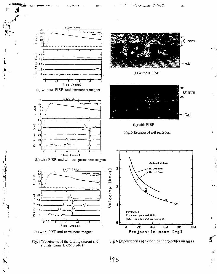
<
S0
**> 28 j- ,. _
III I'1 •' _
z-:OT 275r
" — .
e .2 .e 1
(a) without PISP and permanent magnet
SHOT 2772
E Iu !" 32 r
S ze -
T i n s Crr.ss::}
(b) with PISP and without permanent magnet
=-iO" 2 7 S 2 m 3V>NE
UO
^ 1
B
(c) with PISP and permanent magnet
Fig.4 Waveforms of the driving current andsignals from B-dot probes.
Rail
(a) without PISP
(b) with PISP
Fig.5 Erosion of rail surfaces.
B.-0.53T
Current paak—2IkR
R.L:Rccsler«tIon Length
I . I • I . I
0.1mm
Rail
0 20 40 60 80 100Projectile mass Cmg]
Fig.6 Dependencies of velocities of projectiles on mass.