
Feasibility of a new domestic CHP trigeneration with heat pump: I. Design and development
11
Feasibility of a new domestic CHP trigeneration with heat pump: I. Design and development J.L. M ıguez, S. Murillo, J. Porteiro, L.M. L opez * E.T.S. Ingenieros Industriales, Universidad de Vigo, Campus Lagoas-Marcosende, 36200 Vigo, Spain Received 17 November 2003; accepted 9 January 2004 Available online 12 February 2004 Abstract A new small-scale total energy system is proposed and studied. The system mainly consists of a recip- rocating internal combustion engine moving an electric generator and a heat recovery system. Simulta- neously, the engine drives a heat pump compressor. The heat pump is reversible and meets the summer refrigerating load and helps to meet the winter thermal demand. Such a system is able to provide electricity, heating, hot water and refrigeration autonomously over the whole year. The analysis of its performance is presented. Ó 2004 Elsevier Ltd. All rights reserved. Keywords: Cogeneration; HVAC system; Domestic; Heat pump; Total energy 1. Introduction Cogeneration or combined heat and power have proven interesting as a solution when increasing an energy production systemÕs global efficiency, thus reducing carbon dioxide emis- sions. Therefore, central governments and official agencies are promoting its development and application. It is also included in the EC White Paper on Energy [1]. However, due to its technical complexity and its higher purchase and maintaining costs, it is not so competitive in sectors characterized by low consumption such as domestic and small commercial markets. The introduction of cogeneration systems in the domestic sector requires the development of compact, cost efficient, noiseless, easy to install and low maintenance systems, capable of * Corresponding author. Address: Departamento de Ingenier ıa Meca ´nica, Universidad de La Rioja, C/Luis de Ulloa, 20, 26004 Logro~ no (La Rioja), Spain. Tel.: +34-941-299-536; fax: +34-941-299-478. E-mail addresses: [email protected] (J.L. M ıguez), [email protected] (L.M. L opez). 1359-4311/$ - see front matter Ó 2004 Elsevier Ltd. All rights reserved. doi:10.1016/j.applthermaleng.2004.01.008 Applied Thermal Engineering 24 (2004) 1409–1419 www.elsevier.com/locate/apthermeng
Transcript of Feasibility of a new domestic CHP trigeneration with heat pump: I. Design and development
Applied Thermal Engineering 24 (2004) 1409–1419www.elsevier.com/locate/apthermeng
Feasibility of a new domestic CHP trigeneration withheat pump: I. Design and development
J.L. M�ıguez, S. Murillo, J. Porteiro, L.M. L�opez *
E.T.S. Ingenieros Industriales, Universidad de Vigo, Campus Lagoas-Marcosende, 36200 Vigo, Spain
Received 17 November 2003; accepted 9 January 2004
Available online 12 February 2004
Abstract
A new small-scale total energy system is proposed and studied. The system mainly consists of a recip-
rocating internal combustion engine moving an electric generator and a heat recovery system. Simulta-
neously, the engine drives a heat pump compressor. The heat pump is reversible and meets the summer
refrigerating load and helps to meet the winter thermal demand. Such a system is able to provide electricity,heating, hot water and refrigeration autonomously over the whole year. The analysis of its performance is
presented.
� 2004 Elsevier Ltd. All rights reserved.
Keywords: Cogeneration; HVAC system; Domestic; Heat pump; Total energy
1. Introduction
Cogeneration or combined heat and power have proven interesting as a solution whenincreasing an energy production system�s global efficiency, thus reducing carbon dioxide emis-sions. Therefore, central governments and official agencies are promoting its development andapplication. It is also included in the EC White Paper on Energy [1]. However, due to its technicalcomplexity and its higher purchase and maintaining costs, it is not so competitive in sectorscharacterized by low consumption such as domestic and small commercial markets.The introduction of cogeneration systems in the domestic sector requires the development
of compact, cost efficient, noiseless, easy to install and low maintenance systems, capable of
* Corresponding author. Address: Departamento de Ingenier�ıa Mecanica, Universidad de La Rioja, C/Luis de Ulloa,20, 26004 Logro~no (La Rioja), Spain. Tel.: +34-941-299-536; fax: +34-941-299-478.
E-mail addresses: [email protected] (J.L. M�ıguez), [email protected] (L.M. L�opez).
1359-4311/$ - see front matter � 2004 Elsevier Ltd. All rights reserved.doi:10.1016/j.applthermaleng.2004.01.008

1410 J.L. M�ıguez et al. / Applied Thermal Engineering 24 (2004) 1409–1419
providing energy to a single dwelling over the whole year. This has attracted the attention ofseveral researchers, with new proposals and studies on this topic. [2–4].The incorporation of heat pumps to the traditional cogeneration scheme (engine, electric
generator, residual heat recovery system) has proven to enhance its capacity, flexibility and overallperformance [5–8]. Furthermore, the addition of some specific auxiliary equipment will allow thesystem to satisfy domestic energy demands, economically, over the whole year with no need forany other energy source. This alternative constitutes a total energy system called thermo-electric
autonomous group referred to here as TEAG. The description of such a system and its developmentare presented in this paper.
2. Plant design and basic operation
The system consists mainly of a gas alternative internal combustion engine (diesel or petrolengines may be used as well) driving directly an electric generator and, through a belt drive, apulley coupled to an electromagnetic clutch which drives the heat pump compressor.The engine is water cooled in order to ease heat recovery. Exhaust gases pass through a heat
exchanger transferring part of its heat to the system. The reversibility of the heat pump allows thesystem to meet summer demand, and helps the system to satisfy winter�s higher thermal demands.Therefore, generation and thermal demands are better met and greater use of the heating pump isachieved, leading to a higher overall thermal efficiency.The main structure of the system is shown in Fig. 1. The arrangement of several of its elements
may be altered in order to fit better to particular circumstances; however, a generic configurationis presented here for study. An interesting alternative could entail introducing a heat exchanger
Fig. 1. Schematic diagram of experimental plant configuration.

Fig. 2. Prototype plant.
J.L. M�ıguez et al. / Applied Thermal Engineering 24 (2004) 1409–1419 1411
between the residual heat recovery system and the heat pump. This option is not represented inFig. 2 but is analyzed in this paper. The thermal accumulator and the batteries permit easiercontrol of the system as well as a better response to the irregular thermal and electrical demands.Depending on energy demands and accumulator status the system may operate in five different
modes, each with very different performance and efficiency as will be analyzed later:
• Stand-by mode (SB): when the absence of any demand or when the high levels of the accumu-lators allow the system to turn the internal combustion engine off.
• Electric generator mode (EG): when due to the lack of thermal demands or due to the high levelof thermal accumulation, the system only drives the electric generator without recovering theresidual engine heat which is, therefore, ejected to the atmosphere.
• Co-generation mode (CG): when the system drives the electric generator charging the batteriesand supplying electricity. The residual heat recovered is used for heating up the thermal accu-mulator or for attending to domestic demands.
• Heat pump winter mode (HPW): when heat demand is high, the internal combustion systemdrives the electric generator and the compressor. The thermal output is from both recoveredheat and heat pump.
• Heat pump summer mode (HPS): when refrigeration is needed, with or without thermal andelectrical demands, the internal combustion engine drives the electric generator and the com-pressor. The residual heat recovered may be used to generate hot water (if needed) while theheat pump is inverted to operate as an air conditioning system. With the proposed configura-tion no cold-accumulation is possible leading to a direct relation between refrigeration outputand engine operation.

1412 J.L. M�ıguez et al. / Applied Thermal Engineering 24 (2004) 1409–1419
3. Prototype plant development
A prototype plant has been designed and developed so as to evaluate the overall performance ofthe TEAG concept. During its construction, several decisions that may have slightly affected thesystem�s overall performance had to be taken. These aspects will be explained as they arise in thispaper.Commercial and standard components have been chosen in the main; however, some com-
ponents were not available and had to be fully developed. In addition, almost every commercialcomponent required some degree of modification.The development of a prototype plant required a previous dimensioning stage. This first step
required the identification of typical domestic energy demands for a determined application andemplacement (Table 1). Taking into account several studies focused on single-dwelling applica-tions [9] and traditional systems, we took for our purposes the following desired rated output:Having inspected the market and taking into consideration several studies published [10–19],
the main components of the prototype plant are listed in Table 2. The selection criteria wereperformance, availability, cost, and compact design, which lead us in several cases to selectautomotive systems.
Table 1
Single-dwelling system�s desired rated output
Concept kW
Electric power 3–4
Central heating 25–35
Hot water generation 20–30
Air conditioning 10–15
Table 2
Selected equipment for prototype plant construction
Sub-system Description
Engine
Constructor and type Honda GX 360-K1
Displacement 359 cm3
Rated power 9.6 kW @ 3600 rpm
Main features V-2 Water cooled
Fuel Gas (modified from original)
HP’s compressor
Constructor and type Sankyo SD-510
Displacement 161 cm3
Rated power 7 kW @ 4000 rpm
Construction, type 5 axial pistons
Refrigerant R-134a
Electric generator
Constructor and type C.A.V. 200A
Regulator FEMSATRONIC RF4 24X-3
Rated power 4800 VA

Fig. 3. Experimental energy distribution in a spark ignition engine.
J.L. M�ıguez et al. / Applied Thermal Engineering 24 (2004) 1409–1419 1413
The heat accumulator shown in Fig. 2 is of key importance in the system�s seasonal effective-ness. A small accumulator will not cushion the differences in time and value between thermal andelectrical demands, while an oversized accumulator will lead to higher heat losses, higher costs,excessive thermal inertia in the system and a break with the compactness philosophy. For thatreason, the prototype plant was constructed with a 500 dm3 thermal accumulator made ofstainless steel. The maximum operating temperature of the accumulator was selected at 75 �C.This means that with an admitted temperature drop of 30 �C the stored heat will be 17.4 kWh. Onthe other hand, the size of the batteries will balance between keeping the purchase and mainte-nance cost low and keeping the engine from starting and stopping pointlessly. For the prototypeplant, a 24 V–400 Ah set, made of eight 12 V–100 Ah lead-acid batteries was chosen. The ratedelectric energy accumulated reaches 9.6 kWh.Another main characteristic of this system is that the engine, and thus its driven compo-
nents, works with variable speed, which allows the system to operate, as far as possible, underits best performance conditions. The system�s control selects the desired speed, acting directlyon the engine�s centrifugal throttle auto-control, which maintains the engine at the desiredspeed. Fig. 3 shows the expected energy distribution of the fuel input with engine load. It canbe deduced, therefore, that the desired range of operation is from 90% to 70% of full load.Thus, the speed controller function is to select the speed that stabilizes the engine inside thementioned range.
4. System analysis
In this section, the analysis of the proposed plant operating in its different modes will besummarized. These different modes of operation are similar to those proposed by Smith et al.[3,4]. Data shown are the result of partial and global prototype plant analyses.
1414 J.L. M�ıguez et al. / Applied Thermal Engineering 24 (2004) 1409–1419
4.1. Stand by mode (SB)
When there is an absence of thermal and electrical demands or when the thermal accumulatorand batteries are charged, the controller determines that there is no need for further generationand turns off the internal combustion engine. The system stays in SB mode until new demandsappear or until the accumulation falls below a set limit.Batteries supply electricity for the system and domestic consumption. System demands are: the
system�s control and circulating pumps.
4.2. Electric generator mode (EG)
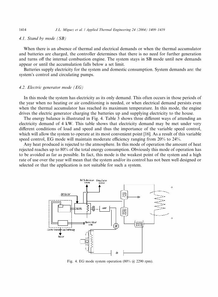
In this mode the system has electricity as its only demand. This often occurs in those periods ofthe year when no heating or air conditioning is needed, or when electrical demand persists evenwhen the thermal accumulator has reached its maximum temperature. In this mode, the enginedrives the electric generator charging the batteries up and supplying electricity to the house.The energy balance is illustrated in Fig. 4. Table 3 shows three different ways of attending an
electricity demand of 4 kW. This table shows that electricity demand may be met under verydifferent conditions of load and speed and thus the importance of the variable speed control,which will allow the system to operate at its most convenient point [16]. As a result of this variablespeed control, EG mode will maintain moderate efficiency ranging from 20% to 24%.Any heat produced is rejected to the atmosphere. In this mode of operation the amount of heat
rejected reaches up to 80% of the total energy consumption. Obviously this mode of operation hasto be avoided as far as possible. In fact, this mode is the weakest point of the system and a highrate of use over the year will mean that the system and/or its control has not been well designed orselected or that the application is not suitable for such a system.
Fig. 4. EG mode system operation (80% @ 2290 rpm).

Table 3
Engine operation and energy distribution at EG mode rated power (4 kW)
Engine operation Electric output
(kW)
Exhaust losses
(kW)
Refrigeration losses
(kW)
COP
100% @ 2115 rpm 4.00 4.96 5.70 0.217
80% @ 2290 rpm 4.00 4.33 5.33 0.244
60% @ 3190 rpm 4.00 4.69 5.85 0.233
J.L. M�ıguez et al. / Applied Thermal Engineering 24 (2004) 1409–1419 1415
The electrical output of the system operating in EG mode at different loads and speeds is shownin Fig. 5. Due to the absence of any mechanical demand other than the electric generator, theengine cannot reach every operation point and thus its performance range is reduced. This modeof operation is the same as a commercial set electric generator and its poor performance is wellknown.
4.3. Cogeneration mode (CG)
In this mode, the system must not only meet electricity demand but also a moderate thermalenergy demand. This mode of operation evokes the operation of the engine�s residual heatrecovery system. The system accumulates the heat recovered in the thermal accumulator, whichwill fit the engine�s thermal output to the thermal demand.The system controls the accumulator temperature and the thermal demand and decides whether
thermal accumulator temperature is sustainable with the actual thermal output or not betweenpredetermined limits. When the thermal accumulator�s temperature goes over a determined limit(in our case 75 �C), the system will switch to EG or SB mode depending on the electricity demand
Fig. 5. EG mode electrical output.

1416 J.L. M�ıguez et al. / Applied Thermal Engineering 24 (2004) 1409–1419
and the status of the batteries. If it falls under the lower limit (45 �C in the prototype plant) orwhen if the temperature decrease is steep, the controller will decide between increasing enginespeed or changing to HPW mode to enhance thermal output.The energy balance of this mode is in Fig. 6 and in Table 4.In Table 4 it can be seen that an increase in engine speed will lead to a higher COP, which
contrast with the fact that operating at 60% is less efficient than operating at 80%. The reason isthat heat recovery at a higher speed is a little better leading to a slightly higher COP at the sameelectric output (see Fig 7). Thus, the controller may decide to increase engine speed to enhancethermal output due to the smaller load needed to meet mechanical demand at a higher speed.It will be seen that HPW mode is the most efficient but it may not be able to meet a high
electrical demand. In such a case, the controller switches to CG mode and allows the engine tooperate at high speed and partial load so as to provide the electricity necessary without greatlyreducing thermal output. Thus, CG mode will also be triggered when the system needs a highelectric output.
4.4. Heat pump summer mode (HPS)
This operation mode is adopted whenever a refrigerating demand exists. Electrical demand andsome eventual thermal demand may also exist. In such a mode, the use of the heat pump is
Fig. 6. CG mode system operation (80% @ 2290 rpm).
Table 4
Engine operation and energy balance at CG mode rated power (4 kW)
Engine operation Electric output (kW) Thermal output (kW) Total loses COP
100% @ 2115 rpm 4.00 8.64 4.41 0.688
80% @ 2290 rpm 4.00 7.90 3.15 0.728
60% @ 3190 rpm 4.00 8.60 3.26 0.733

0
5
10
15
20
25
30
35
40
45
50
55
60
65
70
75
80
0 10 20 30 40 50 60 70 80 90 100Percent of Full Load
Perc
ent o
f Fue
l Inp
ut
Thermal Output
Electrical output
Lube oil
Other losses
Fig. 7. CG mode fuel input distribution with load.
J.L. M�ıguez et al. / Applied Thermal Engineering 24 (2004) 1409–1419 1417
inevitable and the engine must drive the compressor and the electric generator. The heat pumpoperates as air conditioning, extracting heat from the dwelling to the exterior [13].If there is a thermal demand, typically in form of hot water, the residual heat from the engine
and the heat from the condenser unit are recovered, otherwise both are rejected. These casesrepresent the opposite extremes of HPS operation. Figs. 8 and 9 show a schematic representationof HPS mode operation when there are no heating or hot water demands.Table 5 shows the differences in performance between operation without heat recovery (HPS),
operation with engine heat recovery (HPS+R), and operation with engine and condenser heatrecovery (HPS+R+C). The HPS+R+C mode has COP of 1.67 because the heat extracted from thedwelling is being pumped to the heat accumulator and thus re-pumped as hot water.
4.5. Heat pump winter mode (HPW)
HPW operation is required when the thermal output of the system operating in CG mode is notenough to meet thermal demand and, as a result, the temperature of the heat accumulator hasfallen. However, this situation may be predicted when the system�s control estimates that thethermal demand is not reachable without the use of the heat pump, changing to HPW before thetemperature of the accumulator has fallen beyond the lower limit. HPW may also be triggeredevery time the thermal demand exists without a substantial electricity demand, being the onlymethod of loading up the engine without electric generation.Due to the importance of this mode of operation and bearing in mind that it is the real purpose
of the system�s design, it will be treated thoroughly in the second part of this work: Feasibility of a
new domestic CHP trigeneration with heat pump: II. Availability analysis.

Fig. 9. HPS mode electrical and thermal output.
Fig. 8. HPS mode system performance (electric output 1.5 kW).
Table 5
HPS mode alternatives and their performance
System operation Thermal con-
sumption (kW)
Electric output
(kW)
Refrigerating
output (kW)
Thermal output
(kW)
COP
HPS 18.1 1.50 9.10 0 0.59
HPS+R 18.1 1.50 9.10 8.7 1.07
HPS+R+C 18.1 1.50 9.10 19.6 1.67
1418 J.L. M�ıguez et al. / Applied Thermal Engineering 24 (2004) 1409–1419

J.L. M�ıguez et al. / Applied Thermal Engineering 24 (2004) 1409–1419 1419
5. Conclusions
The aim of this work was to examine the TEAG concept, design and availability for domesticuse. By comparing its different modes of operation we can conclude that the role of the heat pumpis crucial for the enhancement of a system�s overall efficiency. Future work will be conductedtowards increasing the heat pump�s contribution.
Acknowledgements
This work was supported by the Secretaria Xeral de Investigaci�on e Desenvolvemento (Xunta deGalicia, Spain) under the project PGID T01 ENR 30302 PR.
References
[1] European Union, White Paper: An energy policy for the european union, COM (95) 682, December 1995.
[2] GRI 1986, Gas-engine heat pump test procedures, Topical Report GRI-86/0083, Gas Research Institute, Chicago.
[3] M.A. Smith, P.C. Few, Domestic-scale combined heat-and-power system incorporating a heat pump: analysis of a
prototype plant, Applied Energy 70 (2001) 215–232.
[4] M.A. Smith, P.C. Few, J.W. Twidell, Modelling of a domestic CHP plant incorporating a heat pump, International
Journal of Energy 22 (7) (1997).
[5] R.M. Lazzarin, G.A. Logno, P.C. Romagnoti, A new HVAC system based on cogeneration by an IC engine,
Applied Thermal Energy 16 (7) (1996) 551–559.
[6] R.M. Lazzarin, A. Gasparella, New ideas of energy utilization in combined heat and power with cooling:
I. Principle, Applied Thermal Energy 17 (4) (1997) 369–384.
[7] R.M. Lazzarin, A. Gasparella, New ideas of energy utilization in combined heat and power with cooling:
II. Applications, Applied Thermal Energy 17 (5) (1997) 479–500.
[8] J. Porteiro, J.L. M�ıguez, S. Murillo, L.M. L�opez, Posibilidad del empleo de peque~nos grupos termo-el�ectricos conbomba de calor a gas, El Instalador (Noviembre) (2001) 95–109.
[9] SEDIGAS, Estudio econ�omico de alternativas energ�eticas en la vivienda (I a VI), El Instalador, 2000, pp. 362–367.[10] L.M. L�opez, Determination of energy and exergy of waste at the industry of the Basque Country, Applied ThermalEngineering 18 (3–4) (1998) 187–197.
[11] J.B. Heywood, Internal Combustion Engines Fundamentals, McGraw-Hill, 1988, pp. 668–711.
[12] H. Heisler, Advance Engine Technology, SAE International, 1995, pp. 658–698.
[13] ISO 1995, Reciprocating internal combustion engines––Performance––Part 1. Standard reference conditions,
declarations of power, fuel and lubricating oil consumptions, and test methods, Standard 3046-1-95, International
Organization for Standardization, Geneva, Switzerland.
[14] S. Murillo, J. Porteiro, J.L. M�ıguez, et al., Grupo Aut�onomo Termo-El�ectrico como sistema energ�etico eficiente, in:V Congreso Iberoamericano de Ingenier�ıa Mec�anica (International), Venezuela, 2001.
[15] J.L. M�ıguez, J. Porteiro, S. Murillo, et al., Ahorrro de energ�ıa mediante el empleo de motocalefacci�on a gas, in:CIAR 2001, Argentina, 2001.
[16] HVAC Systems and Equipment, 2000 ASHRAE Handbook, SI Edition, 47.1–47.11 (2000), Engine driven heating.
[17] HVAC Systems and Equipment, 2000 ASHRAE Handbook, SI Edition, 34.1–34.36 (2000), Compresores.
[18] HVAC Systems and Equipment, 2000 ASHRAE Handbook, SI Edition, 43.1–43.6 (2000), Intercambiadores de
calor.
[19] HVAC Systems and Equipment, 2000 ASHRAE Handbook, SI Edition, 7.1–7.24 (2000), Cogeneraci�on.