ML5000 Service Manual | Allen & Heath
135
ALLEN&HEATH WARNING – HIGH VOLTAGES Power Supply Unit (PSU) work should only be carried out by qualified personnel. We recommend that you use an approved Allen & Heath service centre for all power supply work. Please contact your local Allen & Heath distributor for more details. http://www.allen-heath.com/
-
Upload
khangminh22 -
Category
Documents
-
view
0 -
download
0
Transcript of ML5000 Service Manual | Allen & Heath

ALLEN&HEATH
WARNING – HIGH VOLTAGES
Power Supply Unit (PSU) work should only
be carried out by qualified personnel.
We recommend that you use an approved Allen & Heath
service centre for all power supply work.
Please contact your local Allen & Heath distributor for more details.
http://www.allen-heath.com/

ALLEN&HEATH
ML5000
SERVICE MANUAL
Publication AP3737
Dual Function Live Sound Console
2 ML5000 Service Manual
Introduction
This service manual provides technical information on the Allen & Heath ML5000 audio console. Included is the technical specification, system block diagram, circuit schematics with board layouts, and a spare parts list. Information on the power supply is available in a separate publication. Only technically qualified service personnel should carry out service work on the console and its power supply.
Whilst we believe the information in this manual to be reliable we do not assume responsibility for inaccuracies. We also reserve the right to make changes in the interest of further product development.
We are able to offer further product support through our world-wide network of approved dealers and service agents. You can also access our Web site on the Internet for information on our product range and further technical support. To help us provide the most efficient service please keep a record of the console serial number, and date and place of purchase to be quoted in any communication regarding this product. The serial number is located on the rear panel.
Check out our home site for information on the company and its pedigree, our full product range and our design philosophy.
www.allen-heath.com
ML5000 Service Manual AP3737 Issue 2
Copyright © 2002 Allen & Heath. All rights reserved
This product complies with the European Electromagnetic Compatibility directives 89/336/EEC & 92/31/EEC and the European Low Voltage Directives 73/23/EEC & 93/68/EEC.
This product has been tested to EN55103 Parts 1 & 2 1996 for use in Environments E1, E2, E3, and E4 to demonstrate compliance with the protection requirements in the European EMC directive 89/336/EEC. During some tests the specified performance figures of the product were affected. This is considered permissible and the product has been passed as acceptable for its intended use.
Allen & Heath has a strict policy of ensuring all products are tested to the latest safety and EMC standards. Customers requiring more information about EMC and safety issues can contact Allen & Heath.
NOTE: Any changes or modifications to the console not approved by Allen & Heath could void the compliance of the console and therefore the users authority to operate it.
Manufactured in the United Kingdom by Allen & Heath
Kernick Industrial Estate, Penryn, Cornwall, TR10 9LU, UK
http://www.allen-heath.com
ML5000 Service Manual 3
Contents
Important Safety Instructions ............................4
Mains Plug Wiring Instructions .........................5
General Precautions .........................................5
ML5000 Key Features ......................................6
Front Panel Layout............................................7
Rear Panel Layout ............................................8
Functional Description ......................................9
Installing the Console......................................10
The Expander Sidecar ....................................11
The MPS14 Power Supply..............................14
Technical Specifications .................................16
System Block Diagram....................................17
Connector Types and Wiring ..........................19
Gain Structure.................................................20
Internal Jumper Options .................................21
MIDI ................................................................22
Operating Software Technical Support...........24
Servicing the Input Faders..............................25
Servicing the Master Faders...........................27
Base Removal and Internal Assemblies.........29
Removing a Mono Input Assembly .................30
Removing the Master Distribution...................31
Servicing the Meterbridge...............................32
Servicing the MPS14 Power Supply ...............33
Ordering Consoles and Accessories ..............34
Ordering Assemblies.......................................35
Ordering Spare Parts ......................................37
Channel Cue Sheet (Blank) ............................42
Master Cue Sheet (Blank) ..............................43
Service Notes (Blank) .....................................44
TECHNICAL DRAWINGS .................. Section D

4 ML5000 Service Manual
Important Safety Instructions
WARNINGS - Read the following before proceeding :
ATTENTION: RISQUE DE CHOC ELECTRIQUE – NE PAS OUVRIR
Read instructions: Retain these safety and operating instructions for future reference. Adhere to all warnings printed here and on the console power unit. Follow the operating instructions printed in the user guide and the power unit user guide.
Do not remove covers: Operate the power unit with its covers correctly fitted. Refer any service work to competent technical personnel only.
Power sources: Connect the power unit to a mains power only of the type described in the User Guide and marked on the rear panel. Use the power cord with sealed mains plug appropriate for your local mains supply as provided with the console. If the provided plug does not fit into your outlet consult your service agent for assistance.
Power cord routing: Route the power cord so that it is not likely to be walked on, stretched or pinched by items placed upon or against it.
Grounding: Do not defeat the grounding and polarisation means of the power cord plug. Do not remove or tamper with the ground connection in the power cord.
Water and moisture: To reduce the risk of fire or electric shock do not expose the power unit or console to rain or moisture or use it in damp or wet conditions. Do not place containers of liquids on it which might spill into any openings.
Ventilation: Do not obstruct the ventilation slots or position the console or power unit where the air flow required for ventilation is impeded. If the console is to be operated in a flightcase ensure that it is constructed to allow adequate ventilation.
Heat and vibration: Do not locate the power unit in a place subject to excessive heat or direct sunlight as this could be a fire hazard. Locate the console and its power unit away from any equipment which produces heat or causes excessive vibration.
Servicing: Switch off the equipment and unplug the power cord immediately if it is exposed to moisture, spilled liquid, objects fallen into the openings, the power cord or plug become damaged, during lightening storms, or if smoke, odour or noise is noticed. Refer servicing to qualified technical personnel only.
Installation: Install the console in accordance with the instructions printed in the User Guide. Do not connect the output of power amplifiers directly to the console. Use audio connectors and plugs only for their intended purpose.
CAUTION
WARNING: This equipment must be earthed.

ML5000 User Guide 5
Important Mains Plug Wiring Instructions. The power unit is supplied with a moulded mains plug fitted to the AC mains power lead. Follow the instructions below if the mains plug has to be replaced.
The mains lead wires are coloured in accordance with the following code:
WIRE COLOUR TERMINAL
European USA/Canada
L LIVE BROWN BLACK
N NEUTRAL BLUE WHITE
E EARTH GND GREEN & YELLOW GREEN
The wire which is coloured Green and Yellow must be connected to the terminal in the plug which is marked with the letter E or with the Earth symbol. This appliance must be earthed.
The wire which is coloured Blue must be connected to the terminal in the plug which is marked with the letter N.
The wire which is coloured Brown must be connected to the terminal in the plug which is marked with the letter L.
Ensure that these colour codes are followed carefully in the event of the plug being changed.
General Precautions
Damage : To prevent damage to the controls and cosmetics avoid placing heavy objects on the control surface, scratching the surface with sharp objects, or subjecting the console to rough handling and vibration.
Environment : Protect from excessive dirt, dust, heat and vibration when operating and storing. Avoid tobacco ash, smoke, drinks spillage, and exposure to rain and moisture. If the console becomes wet, switch off and remove mains power immediately. Allow to dry out thoroughly before using again.
Radiation : To avoid induced noise and interference pickup do not operate the console close to strong sources of electromagnetic radiation such as power supplies, video monitors, lighting cables and dimmers.
Cleaning : Avoid the use of chemicals, abrasives or solvents. The control panel is best cleaned with a soft brush and dry lint-free cloth. Stubborn marks can be removed using a cloth dampened with isopropyl alcohol. Do not leave marking tape stuck to the console for long periods of time as the adhesive can degrade and leave a sticky residue. The faders, switches and potentiometers are lubricated for life. The use of electrical lubricants on these parts is not recommended. Refer to the power unit user guide for instructions on cleaning its ventilation filters.
Transporting : The console should be transported in the original packing or purpose built foam lined flightcase. Protect the control surface from damage during transit. The console is a large and heavy item. To avoid injury ensure adequate man power and precaution when lifting or moving the console.

6 ML5000 Service Manual
ML5000 Key Features
The Allen & Heath ML5000 is a large format VCA equipped dual function live sound console. It can be quickly configured for front-of-house (FOH) or stage monitor mixing. As one console suitable for both applications it is equally well suited to installation, rental and touring. It offers an IO capability and feature set that satisfies the latest trends in live sound engineering, in particular the growing number of inputs and outputs for multi-speaker house and monitor systems, demands of stereo in-ear monitoring, 3 speaker LCR imaging, advanced grouping and automation. The design ensures on-the-road durability, a clear layout for easy walk up and go operation, and no compromise audio performance.
Inputs and Outputs
• 3 Standard frame sizes: 32+4, 40+4, 48+4 (mono + stereo channels)
• 32, 40, 48 mono mic/line inputs with inserts and direct outputs
• 4 dual stereo line inputs
• 24 input sidecar to expand to a maximum 96 inputs
• Main Left, Right and Centre outputs with inserts, C configurable as the engineers monitor
• 8 Groups, 16 Auxes: Group/Aux 1-8 and Aux 9-16 with faders and inserts, Aux 1-8 with rotaries
• Matrix 1-8 with inserts and external inputs
• 2-Track monitor input and recording send
• Stereo headphones and local monitors
• Dual mic talkback input
• ClearCom compatible intercom interface
Groups and Automation
• 8 VCA groups with mutes and PAFL monitoring
• 8 audio groups with LCRplus™ subgrouping
• 8 mute groups
• 128 snapshot memories for mute and/or VCA assignment store, recall and preview
• Solo-in-place with all-clear and toggle-last
• MIDI mute on/off, snapshot recall and dump in/out control
• Channels can be made safe independently from the automation and solo-in-place
Processing and Control
• 4-Band full sweep mono EQ with fully parametric mids, 4-band fixed frequency stereo EQ
• Sweepable high pass filter
• LCRplus™ 3 speaker imaging system
• Protected mode switching to configure the console for FOH or monitor application
• Intelligent PAFL system with all-clear, PFL/in-place AFL, priority, auto-cancel/add mode…
• Assignable talkback and intercom
• 1kHz tone and pink noise generator for system line-up and testing
• Full console monitoring and extensive metering of inputs, mix busses and outputs
ML5000 Service Manual 7
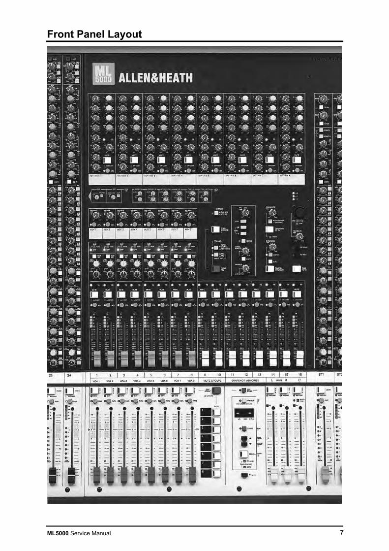
Front Panel Layout

8 ML5000 Service Manual
Rear Panel Layout

ML5000 Service Manual 9
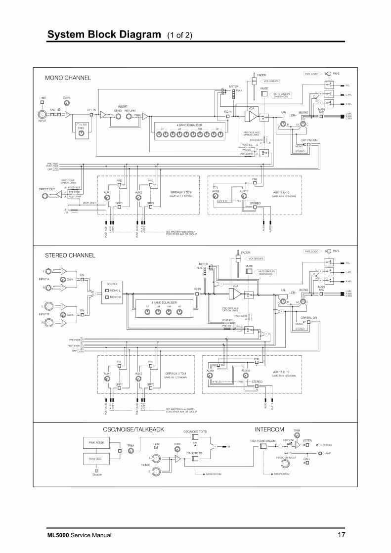
MONO INPUT and EQ. The input preamp matches microphone or line level signals to the console. The sweepable high pass filter removes unwanted low frequency sounds below the selected frequency. The channel insert is post filter, pre EQ. A swept frequency 4 band equaliser provides shelving high and low bands with adjustable shelf frequency, and fully parametric high and low mid bands with adjustable centre frequency and Q. The filter and EQ can be independently switched in or out.
GRP/AUX SENDS. This section provides controls for the group routing and auxiliary sends. Controls 1-8 function according to the setting of the mode switches in the master section. These configure group routing switches and independent post-fade aux sends for FOH (front-of-house) application, or pre/post switchable sends for stage monitor application. Controls 9-16 can be configured as mono or stereo pre/post aux sends.
MAIN MIX SENDS. A single switch routes the channel signal to the main L, R and C outputs. The balance between the three outputs is determined by the LCRplus pan and blend controls. Pan can also be switched in or out of the group routing for stereo or mono groups.
INPUT FADERS. Includes the channel fader, mute, signal meter and PAFL monitoring. The 8 VCA group assignments are displayed. VCA and mute group editing and channel safe selection is performed using the mute switch with green safe/edit indicator below.
STEREO INPUT and EQ. The input preamp accepts two stereo sources with independent control of each. This allows selection of either or mixing together both sources. A fixed frequency 4 band equaliser provides shelving high and low bands and two bell mid bands. The EQ can be switched in or out.
GRP/AUX 1-8 MASTERS. These are the fader masters for channel sends 1-8, configurable using mode switches as fixed level groups or as variable level pre or post-fade auxes. The output can be routed to the main mix through LCRplus controls to create sub groups. Led meters display the pre-fade mix levels.
AUX 9-16 MASTERS. These are the fader masters for channel sends 9-16.
ROTARY AUX MASTERS. These are the rotary masters for channel post-fade aux sends 1-8. They provide the independent effects sends when the fader masters are configured as groups. They still function when the fader masters are configured as pre/post auxes but would not normally be required.
MAIN MIX FADERS. Provides separate master faders and mutes for the main L, R and C outputs. A mode switch configures the C output as the engineers wedge monitor feed for the stage monitor application.
MATRIX. This section provides all the controls for the 8 matrix outputs, including the source and master rotaries.
VCA GROUPS. These are the VCA group master faders, mutes and PAFL monitor switches. Channels are assigned to the groups using the edit key. The normal fader operating level is marked ‘0’.
MUTE GROUPS. These are the master keys that mute all channels assigned to the group. Channels are assigned using the edit key.
SNAPSHOT MEMORIES. Provides the controls to store, recall and preview the 128 onboard memories, and edit channel safes. Mute settings and/or VCA assignments can be disabled from the snapshots.
HEADPHONES / MONITOR. Provides source selection and independent control of the headphones and local monitor outputs.
SOLO-IN-PLACE. Pressed with the shift key this puts the console into SIP mode ready to solo any channel when its mute key is pressed.
PAFL CONTROL. This section controls how the intelligent PAFL system functions and provides the clear all key.
OSC/NOISE GENERATOR. Enables and selects a 1kHz tone or pink noise which can be routed to any output for line up or system testing.
INTERCOM. The console talkback mic and headphones can be interfaced to a ClearCom compatible intercom system so eliminating the need for a separate intercom headset.
TALKBACK. Pressing the talk switch routes the talkback mic to any output with its TB enable switch selected. The mic input is duplicated on the rear panel for plugging in hand held microphones.
GRP/AUX 1-8 METERS. These moving coil VU meters display the grp/aux 1-8 outputs.
LRC/PAFL METERS. The main L,R and C outputs are simultaneously displayed on both VU and led bar meters. These switch to display any PFL or AFL when selected. The display is mono or mono + stereo depending on source. The large call lamp lights to warn when the intercom is signalled.
AUX 9-16 / MTX 1-8 METERS. These meters display either the aux 9-16 outputs or matrix 1-8 levels according to the setting of the meter select switch near section.

10 ML5000 Service Manual
Installing the Console
Weights 32 Channel 84 kg (185 lbs) 40 Channel 96 kg (211 lbs) 48 Channel 110 kg (242 lbs) 24 Channel sidecar 45 kg (95 lbs) MPS14 psu 6 kg (13 lbs)
130
872
298
HEADPHONES SOCKETSUNDER ARMREST LAMP SOCKETS
ML5000-48 = 2106ML5000-40 = 1851ML5000-32 = 1596ML5000-24SC = 831
90FC 76.2
482.6440
263 REMOVABLE RACK EARS
2U HEIGHT
Refer to the power supply user guide for safety and installation instructions. Heed all warnings printed in the user guide and on the power unit.
Refer to the sidecar user guide for instructions on connecting the sidecar expander to the console.
CAUTION: Ensure adequate ventilation around the power supply unit. Do not operate it where it is subject to excessive heat, for example in direct sunlight or next to power amplifiers. Use forced air cooling such as rack fans if it is operated in a confined or hot space.
ML5000 Service Manual 11
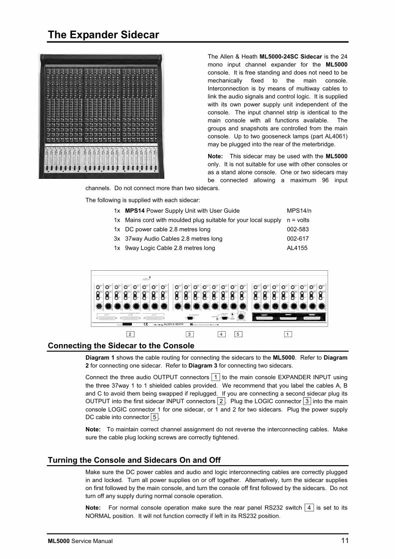
The Expander Sidecar
The Allen & Heath ML5000-24SC Sidecar is the 24 mono input channel expander for the ML5000 console. It is free standing and does not need to be mechanically fixed to the main console. Interconnection is by means of multiway cables to link the audio signals and control logic. It is supplied with its own power supply unit independent of the console. The input channel strip is identical to the main console with all functions available. The groups and snapshots are controlled from the main console. Up to two gooseneck lamps (part AL4061) may be plugged into the rear of the meterbridge.
Note: This sidecar may be used with the ML5000 only. It is not suitable for use with other consoles or as a stand alone console. One or two sidecars may be connected allowing a maximum 96 input
channels. Do not connect more than two sidecars.
The following is supplied with each sidecar:
1x MPS14 Power Supply Unit with User Guide MPS14/n 1x Mains cord with moulded plug suitable for your local supply n = volts 1x DC power cable 2.8 metres long 002-583 3x 37way Audio Cables 2.8 metres long 002-617 1x 9way Logic Cable 2.8 metres long AL4155
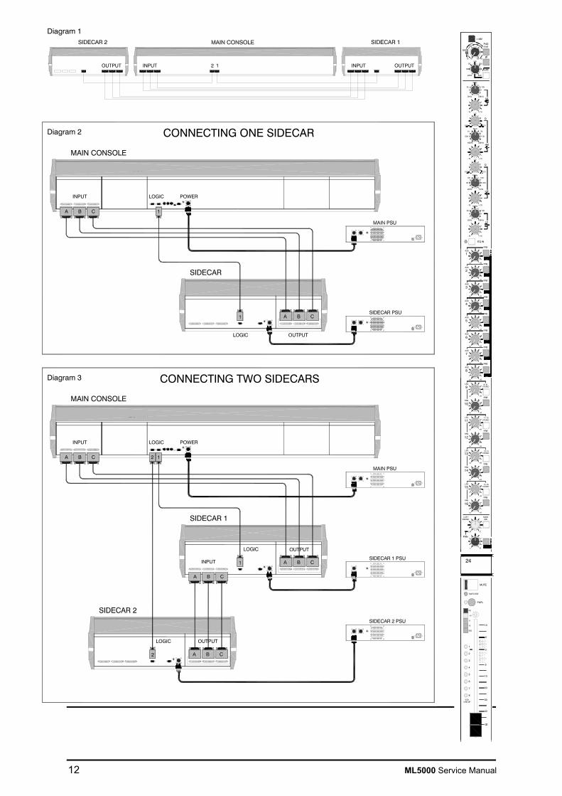
Connecting the Sidecar to the Console Diagram 1 shows the cable routing for connecting the sidecars to the ML5000. Refer to Diagram 2 for connecting one sidecar. Refer to Diagram 3 for connecting two sidecars.
Connect the three audio OUTPUT connectors 1 to the main console EXPANDER INPUT using the three 37way 1 to 1 shielded cables provided. We recommend that you label the cables A, B and C to avoid them being swapped if replugged. If you are connecting a second sidecar plug its OUTPUT into the first sidecar INPUT connectors 2 . Plug the LOGIC connector 3 into the main console LOGIC connector 1 for one sidecar, or 1 and 2 for two sidecars. Plug the power supply DC cable into connector 5 .
Note: To maintain correct channel assignment do not reverse the interconnecting cables. Make sure the cable plug locking screws are correctly tightened.
Turning the Console and Sidecars On and Off Make sure the DC power cables and audio and logic interconnecting cables are correctly plugged in and locked. Turn all power supplies on or off together. Alternatively, turn the sidecar supplies on first followed by the main console, and turn the console off first followed by the sidecars. Do not turn off any supply during normal console operation.
Note: For normal console operation make sure the rear panel RS232 switch 4 is set to its NORMAL position. It will not function correctly if left in its RS232 position.
12 ML5000 Service Manual
INPUT LOGIC
ML5000
A B C 1
POWER
MAIN CONSOLE
INPUT 1 OUTPUT2OUTPUT INPUT
CONNECTING ONE SIDECAR
INPUT LOGIC
ML5000
A B C 1
POWER
MAIN CONSOLE
CONNECTING TWO SIDECARS
2
Diagram 1
Diagram 2
Diagram 3
24
5
7
GROUP
8
VCA
6
4
3
2
1
PAFL
MUTE
PK
-6
SIG
+6
0
SAFE/EDIT
+48V
- 10 10
GAIN
20
4060
30
20Hz 400
10050 200
O
PAD
LR C
=
L R
=
PAN
Q
-15 +15
-15 +15
-15 +15
7kHz
3k
2kHz 20kHz
10k
HF
100Hz
50
20Hz 200Hz
150
LF
100Hz60
20Hz 1kHz
120
30 250
LM
Q
-15 +15
2kHz1k
400Hz 20kHz
3k
HM
EQ IN
HPF
OO +6
OO +6
STEREO9LEV 9-10
10PAN
OO +6
OO +6
STEREOLEV 11-12
12PAN
OO +6
OO +6
STEREOLEV 13-14
14PAN
OO +6
OO +6
STEREOLEV 15-16
16PAN
11
13
15
MAINMIX
LCRBLEND
+
40
0.6 2.5
1.2
500 5k
0.6 2.5
1.2
PRE
PRE
PRE
PRE
20dB
1
OO +6
AUX
2
OO +6
AUX
3
OO +6
AUX
4
OO +6
AUX
5
OO +6
AUX
6
OO +6
AUX
7
OO +6
AUX
8
OO +6
AUX
PRE
PRE
PRE
PRE
PRE
PRE
PRE
PRE
OO
30
5
0
10
5
40
10
20
ML5000 Service Manual 13
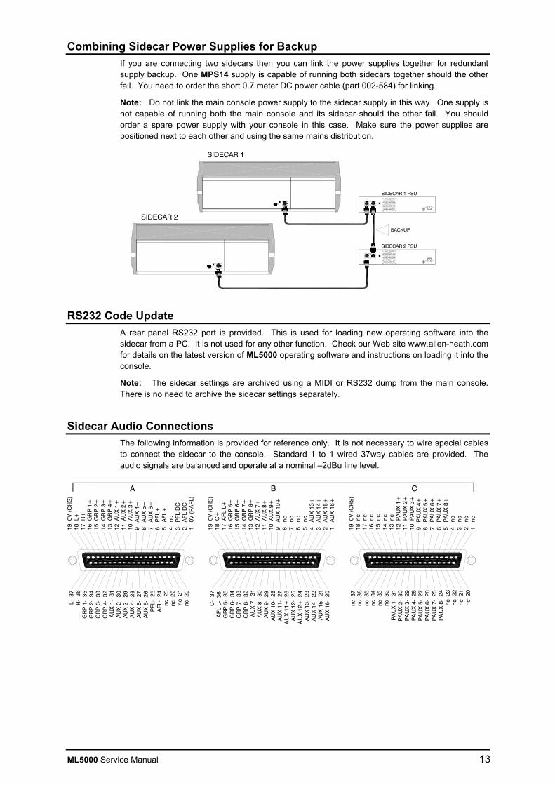
Combining Sidecar Power Supplies for Backup If you are connecting two sidecars then you can link the power supplies together for redundant supply backup. One MPS14 supply is capable of running both sidecars together should the other fail. You need to order the short 0.7 meter DC power cable (part 002-584) for linking.
Note: Do not link the main console power supply to the sidecar supply in this way. One supply is not capable of running both the main console and its sidecar should the other fail. You should order a spare power supply with your console in this case. Make sure the power supplies are positioned next to each other and using the same mains distribution.
RS232 Code Update A rear panel RS232 port is provided. This is used for loading new operating software into the sidecar from a PC. It is not used for any other function. Check our Web site www.allen-heath.com for details on the latest version of ML5000 operating software and instructions on loading it into the console.
Note: The sidecar settings are archived using a MIDI or RS232 dump from the main console. There is no need to archive the sidecar settings separately.
Sidecar Audio Connections The following information is provided for reference only. It is not necessary to wire special cables to connect the sidecar to the console. Standard 1 to 1 wired 37way cables are provided. The audio signals are balanced and operate at a nominal –2dBu line level.
13 n
c12
PA
UX
1+
11 P
AU
X 2
+10
PA
UX
3+
9 P
AU
X 4
+8
PA
UX
5+
7 P
AU
X 6
+6
PA
UX
7+
5 P
AU
X 8
+4
nc
3 n
c2
nc
1 n
c
PA
UX
1-
31P
AU
X 2
- 30
PA
UX
3-
29P
AU
X 4
- 28
PA
UX
5-
27P
AU
X 6
- 26
PA
UX
7-
25P
AU
X 8
- 24
nc 2
3
14 n
c15
nc
16 n
c17
nc
18 n
c19
0V
(C
HS
)nc
37
CBA
13 G
RP
4+
12 A
UX
1+
11 A
UX
2+
10 A
UX
3+
9 A
UX
4+
8 A
UX
5+
7 A
UX
6+
6 P
FL+
5 A
FL+
4 n
c3
PFL
DC
2 A
FL D
C1
0V
(P
AFL
)
GR
P 4
- 32
AU
X 1
- 31
AU
X 2
- 30
AU
X 3
- 29
AU
X 4
- 28
AU
X 5
- 27
AU
X 6
- 26
PFL
- 25
AFL
- 24
nc 2
3nc
22
nc 2
1nc
20
14 G
RP
3+
15 G
RP
2+
16 G
RP
1+
17 R
+18
L+
19 0
V (
CH
S)
GR
P 3
- 33
GR
P 2
- 34
GR
P 1
- 35
R-
36L-
37
13 G
RP
8+
12 A
UX
7+
11 A
UX
8+
10 A
UX
9+
9 A
UX
10+
8 n
c7
nc
6 n
c5
nc
4 A
UX
13+
3 A
UX
14+
2 A
UX
15+
1 A
UX
16+
GR
P 8
- 32
AU
X 7
- 31
AU
X 8
- 30
AU
X 9
- 29
AU
X 1
0- 2
8A
UX
11-
27
AU
X 1
1+ 2
6A
UX
12-
25
AU
X 1
2+ 2
4A
UX
13-
23
AU
X 1
4- 2
2A
UX
15-
21
AU
X 1
6- 2
0
14 G
RP
7+
15 G
RP
6+
16 G
RP
5+
17 A
FL L
+18
C+
19 0
V (
CH
S)
GR
P 7
- 33
GR
P 6
- 34
GR
P 5
- 35
AFL
L-
36C
- 37
nc 3
6nc
35
nc 3
4nc
33
nc 3
2
nc 2
2nc
21
nc 2
0

14 ML5000 Service Manual
The MPS14 Power Supply
The slimline MPS14 power supply uses linear post-regulated switch mode technology to generate the DC voltages required by the console. It will operate from a wide range of ac mains input voltages. Full protection and thermally controlled fan cooling ensures the power unit will operate consistently. The MPS14 also has a built in combiner for connection to a second supply for backup.
Power Supply Installation
Free standing The MPS14 can be operated as a free-standing unit without requiring any special cooling arrangement, but should not be accidentally or deliberately covered in any way. Always stand the unit on a firm flat surface well away from any soft furnishings or carpet.
Rack mounting The MPS14 is designed as a 19 inch rack mount unit and will occupy 2U (3.5 inches) of rack space.
An important consideration when rack-mounting the unit is the need for natural convection of air flow over the whole unit.
Good ventilation below the unit, in the floor or back of the rack, will ensure a path for continuous air flow.
Other equipment in the rack which is known not to produce a significant amount of heat should be mounted below the unit. Equipment which also relies on good airflow within the rack (i.e. most power amplifiers and other power supplies) should be given due consideration and some space should be provided between such units and between the MPS14 unit. Forced convection, by means of a fan-tray, may be desirable in this situation.
Location As with any power supply that contains switch mode technology, it is preferable to provide a degree of physical isolation of the unit from other equipment, particularly that which carries low level audio signals, to avoid any possible interference pick-up. For this reason the unit is provided with a long (2.9m) output cable to enable it to be positioned away from the mixing console. For the same reason, when rack-mounting it is preferable to avoid locating the unit adjacent to signal processing equipment.
Earthing Finally, some consideration should be given to the earthing arrangement of the system, at the centre of which is the console and the MPS14. The console chassis is earthed, to the mains earth, via the power supply. When rack-mounting the MPS14 care should be taken to avoid any possible “ground loops” in the system which would introduce audible hum or buzz to otherwise clean audio signals. Ground loops may occur where signal processing equipment patched to the console, has its signal earth connected to the equipment chassis. A ground loop is formed if the chassis of the signal processing equipment and the MPS14 chassis are in electrical contact through the fixing rails they share in the rack. The MPS14 has audio 0V and mains earth connected internally. If a ground loop is formed operation of the ground lift switch on the rear panel of the MPS14 may improve the situation.
ADVANCED TECHNOLOGY / HIGH POWER DELIVERY / AUTO COMBINING
+18V -18V +10V +48VON PROTECT
CONSOLE POWER SUPPLYMPS14
PIN 1 = +10V @ 5APIN 2 = +17V @ 7A
PIN 4 = A GNDPIN 3 = A GND
PIN 6 = +48V @ 1APIN 7 = -17V @ 7A
PIN 5 = D GND
FUSE
500W MAX100V - 230V.AC 47-63 Hz ~
CAUTION: FOR CONTINUED PROTECTION AGAINST RISK OF FIRE REPLACE FUSE
ATTENTION: REMPLACER LE FUSIBLE AVEC UN DES MEMES CARACTERISTIQUES.WITH SAME TYPE AND RATING. DISCONNECT SUPPLY BEFORE CHANGING FUSE.
DO NOT OPEN. NO USER SERVICEABLE PARTS INSIDE.DO NOT OBSTRUCT VENTILATION OPENINGS.
THIS APPARATUS MUST BE EARTHED BY THE POWER CORD.
COUPER L'ALIMENTATION AVANT DE CHANGER LE FUSIBLE.
WARNING: TO REDUCE THE RISK OF ELECTRIC SHOCKDO NOT EXPOSE THIS APPARATUS TO RAIN OR MOISTURE.
T5A 250V
T
MAINS INPUT
A DIVISION OF HARMAN INTERNATIONAL INDUSTRIES LTD MADE IN ENGLANDS/No
AVIS: RISQUE DE CHOC ELECTRIQUE - NE PAS OUVRIR.
CAUTION

ML5000 Service Manual 15
MPS14 Technical specifications
Mains Input Voltage Range 100 - 240 ± 10% VAC @ 47-63 Hz auto-sensing
Power consumption (max.) 500W
Mains Fuse: 100 - 240 V~ T 5.0A/250V
Internal Fuses:
PCB Ident Fuse type F1 (+12V) T 6.3A 250V 20mm F2 (+48V) T 2A 250V 20mm F18 (aux psu) T 500mA 250V 20mm
DC Outputs
DC Voltage Rail Output Current +17 VOLTS 7A Max. -17 VOLTS 7A Max. +12 VOLTS 5A Max. +48 VOLTS 500mA Max.
DC Output Socket Pin Connections
Pin No: Connection 1 +12 Volts 2 +17 Volts 3 A GND 4 A GND 5 D GND 6 +48 Volts 7 -17 Volts
Overall Dimensions
Front Panel: 482mm x 88mm 19 inch 2U Width (excluding rack ears): 440mm 17.30 inches Height including feet: 90mm 3.5 inches Depth: 260mm 10.25 inches Weight: 6Kg 13 pounds
Cable Assemblies
Assembly Description A&H Part no: DC cable 2.9m MPS14 to ML5000 console cable assembly 002-583
DC LINK cable 0.5m MPS14 to MPS14 PSU “LINKING” cable assembly 002-584
CONSOLE POWER SUPPLYMPS14
PIN 1 = +10V @ 5APIN 2 = +17V @ 7A
PIN 4 = A GNDPIN 3 = A GND
PIN 6 = +48V @ 1APIN 7 = -17V @ 7A
PIN 5 = D GND
MPS14
MPS14
CHASSISGROUND
RS232
DC POWER IN
IN
RET
SENDINSERT
DIRECTOUT
IN
RET
SENDINSERT
DIRECTOUT
IN
RET
SENDINSERT
DIRECTOUT
ML5000

16 ML5000 Service Manual
ML5000 Technical Specifications 0dBu = 0.775 Vrms, +4dBu = 1.23 Vrms Operating Levels Channels......................................... 0dBu Headroom +21dB Mix .................................................. -2dBu Headroom +23dB Frequency Response Referred to 1kHz at +4dBu Mic to main output (+40dB)............. 20Hz to 30kHz +0/-0.5dB Line to main output (0dB)................ 20Hz to 30kHz +0/-0.5dB Distortion @1kHz +14dBu THD+noise ...................................... < 0.01% CMRR Common mode rejection @1kHz Mic (+40dB)..................................... > 80dB Mic + Pad (0dB) .............................. > 50dB Crosstalk Referred to driven channel @1kHz Channel to channel ......................... > -100dB Mute shutoff .................................... > -85dB Fader shutoff ................................... > -90dB Noise Performance Measured rms 22Hz to 22kHz unweighted Mic EIN with 150 ohm source ......... -128dB Residual output noise ..................... < -94dBu (-98dB SN) Mix noise, nothing routed................ < -84dBu (-88dB SN) Mix noise, 24 channels routed ........ < -80dBu (-84dB SN) Metering Reading 0................. +4dBu at XLR outputs LED meters .............. Peak reading, 3 colours VU meters ................ Ave reading, Illuminated moving coil Peak indicators ........ 5dB before clip, multi-point sensing Input meters ............. 5 bar LED (signal, -6, 0, +6, peak) Group mix meters .... 5 bar LED (signal, -6, 0, +6, peak) Group/Mtx meters .... VU L,R,C meters............ VU and 16 bar LED Lamp Connectors x4 Connector ....................................... XLR-F 4pin Rating.............................................. 12V 400mA max
Channel Filters Slope ............................................... 12dB/oct high pass Frequency ....................................... 20Hz to 400Hz variable Mono Equaliser HF................. +/-15dB, 2kHz to 20kHz shelf HM................ +/-15dB, 500Hz to 15kHz bell, Q = 0.6 to 2.5 LM ................ +/-15dB, 35Hz to 1kHz bell, Q = 0.6 to 2.5 LF ................. +/-15dB, 20Hz to 200Hz shelf Stereo Equaliser HF................. +/-15dB, 12kHz shelf HM................ +/-15dB, 2.5kHz bell LM ................ +/-15dB, 250Hz bell LF ................. +/-15dB, 60Hz shelf Power Supply Model MPS14 Type ........................... External 2U rack or floor mount Mains input ................. 100-230V 50/60Hz universal input Power consumption.... 500W Full protection and fan cooling
Dimensions Width.............. Depth ...... .....Height 32 Channel 1596 (62.8”) ... 872 (34.3”) ....298 (11.7”) 40 Channel 1851 (72.9)..... 872.......... .....298 48 Channel 2106 (82.9”) ... 872.......... .....298 Sidecar 831 (32.7”) ..... 872.......... .....298 MPS14 psu 483 (19”) ........ 260 (10.2”) .... Weights 32 Channel..... 84 kg (185 lbs) 40 Channel..... 96 kg (211 lbs) 48 Channel..... 110 kg (242 lbs) 24 Sidecar...... 45 kg (99 lbs) MPS14 psu .... 6 kg (13 lbs)
INPUTS: Mic (Pad out)................ XLR.................balanced, pin2+........ 2k ohm..............variable -60 to -10dBu ........ Max +11dBu Mic (Pad in).................. ........................ ................................. >20k ohm..........variable -40 to +10dBu ....... Max +31dBu Stereo A ...................... TRS jack .........balanced, tip+........... >20k ohm..........variable -18 to +6dBu ......... Max +27dBu Stereo B ...................... XLR.................balanced, pin2+........ >20k ohm..........variable –18 to +6dBu ........ Max +27dBu 2-Track......................... TRS jack .........balanced, tip+ .......... >20k ohm..........+4dBu................................. Max +25dBu Matrix Ext in ................. TRS jack .........balanced, tip+........... >20k ohm..........+4dBu................................. Max +25dBu INSERTS: Input send .................... TRS jack .........ground comp, tip+ .... <50 ohm............0dBu ................................... Max +21dBu Input return................... TRS jack .........balanced, tip+........... >20k ohm..........0dBu ................................... Max +21dBu Output send ................. TRS jack .........ground comp, tip+ .... <50 ohm............-2dBu.................................. Max +21dBu Output return................ TRS jack .........balanced, tip+........... >20k ohm..........-2dBu.................................. Max +21dBu OUTPUTS: L,R,C............................ XLR.................balanced, pin2+........ <75 ohm............+4dBu................................. Max +26dBu Grp/Aux 1-16................ XLR.................balanced, pin2+........ <75 ohm............+4dBu................................. Max +26dBu Matrix 1-8 ..................... XLR.................balanced, pin2+........ <75 ohm............+4dBu................................. Max +26dBu Post Aux 1-8 ................ TRS jack .........ground comp, tip+ .... <50 ohm............-2dBu.................................. Max +21dBu Direct out...................... TRS jack .........ground comp, tip+ .... <50 ohm............0dBu ................................... Max +21dBu 2-Track......................... TRS jack .........ground comp, tip+ .... <50 ohm............+4dBu................................. Max +21dBu Local Monitor ............... TRS jack .........ground comp, tip+ .... <50 ohm............0dBu ................................... Max +21dBu Headphones................. TRS jack .........tip left, ring right........ for stereo headphones >30 ohms
ML5000 Service Manual 17
System Block Diagram (1 of 2)
MONO
STEREO
OPTION LINKSDIRECT OUT
PFL
L AFL
R AFL
L MIXR MIXC MIX
GRP2
AU
X 2
PO
ST
AU
X2
GR
P2
AUX2
PRE
SET MASTER mode SWITCHFOR EITHER AUX OR GROUP
MONO CHANNEL
MUTE
FADER PAFL
MUTE GROUPS
VCA GROUPS
PAFL LOGIC
GRP
GRP/AUX 3 TO 8SAME AS 1,2 SHOWN
VCA
J5
J4
J6
J9
J7 J8J3
J2
J1
+-1
TRIM+48V
TB MIC
2
TALK TO TB
+
OSC/NOISE TO TB
DIM
MONITOR DIM
TB
PINK NOISE
1kHz OSC
TRIM
Disable
OSC/NOISE/TALKBACK
TALK TO INTERCOM
MONITOR DIM
-+
TRIM
SIDETONE LISTEN
TO PHONES
INTERCOM
R LR C
PRE-INSERT
+
+
L
R
C
PEAK
LCR+
PRE-FADEPOST-FADE
ODDEVEN
PRE
GRP PAN ON
AUX1
GRP1
POST-TRIM
PRE-FADE
POST-FADEDIRECT OUT
(AUX1 ONLY)
PO
ST
AU
X1
AU
X1G
RP
1
POST-MUTE
PRE-FADE AUXOPTION LINKS
PRE
AUX9
STEREO CHANNEL
MUTE
FADER PAFL
MUTE GROUPS
VCA GROUPS
PAFL LOGIC
GRP
GRP/AUX 3 TO 8SAME AS 1,2 SHOWN
VCA
J3
R=J2
SNAPSHOTSL AFL
PFL
R AFL
L MIXR MIXC MIX
AU
X10
AU
X1G
RP
1
AU
X 2
GR
P2
AU
X9
+-
+-
GAIN
+-
L
R
R
L
INPUT A
+
ON
ON
MONO L
MONO R
SOURCE
LM HM HF
INPUT
GAIN+48V
PAD HPF IN SEND
LF LM HM HF
EQ IN
FREQ4 BAND EQUALISERFILTER
METER
+-
RETURNINSERT
POST-EQ
PRE-EQ
PAN BLENDMAINMIX
L
+-
CALL
+-
INPUT B GAIN
LF
EQ IN
4 BAND EQUALISER
METER
POST-EQ
PRE-EQ
BAL BLENDMAINMIX
L R LR C
+
+
L
R
C
PEAK
LCR+
PRE-FADE
POST-FADE
PRE
GRP BAL ON
AUX1
GRP1
PO
ST
AU
X1
POST-MUTE
PRE-FADE AUXOPTION LINKS
MONO
STEREO
GRP2
PO
ST
AU
X2
AUX2
PRE
SET MASTER mode SWITCHFOR EITHER AUX OR GROUP
SNAPSHOTS
+
+
L=J1+
LRMLRM
ODDEVEN
AUX10
9-10 LEV STEREOPAN
PRE
AUX9
AU
X10
AU
X9
AUX10
LEV 9-10STEREO
PAN
AUX 11 to 16SAME AS 9,10 SHOWN
AUX 11 to 16SAME AS 9,10 SHOWN
J10
LAMP
INTERCOM IN/OUT

18 ML5000 Service Manual
System Block Diagram (2 of 2)
PEAK
TB
BAL OUTLEFT
TB
AUX = VARIABLE LEVEL+PRE/POST SWITCHGROUP = SWITCHED ROUTING
SET mode FOR EITHER:
L MIX
R MIXSEND
+-
RETURNINSERT
MUTEFADER
PEAK
BAL OUTRIGHT
R MIX
PRE-INSERT
POST-FADE
LPRE-INSERT
POST-FADE
C MIX
SEND
+-
RETURNINSERT
MUTEFADER
PEAK
MIXSEND
+-
RETURNINSERT
MUTEFADER
MUTE GROUPS
mode
METER
INPUT PAFL
AFLPFL
L METERS
R METERS
C METERS
METERS 1-8
METERS 9-16
METER SELECT
GRP/AUX
GRP/AUXMATRIX
OUTPUT AFL
MONITOR
GRP/AUX1
GRP/AUX 2
GRP/AUX 3
GRP/AUX 4
GRP/AUX 5
GRP/AUX 6
GRP/AUX 7
GRP/AUX 8
L
R
C
SEND+-
RETURNINSERT
TB ENABLE
TB
LEVEL
MUTE
BAL OUT
MUTE GROUPSSNAPSHOTS
AFLAFL LOGIC
L AFL
R AFL
MATRIX
MATRIX
L AFL
PFL
R AFL
WEDGE mode
+-
L
+-
2TRKIN
R
OUT2TRK
R
+
PEAKL AFL
R AFL
AFLAFL LOGIC
PANBLEND
MAINMIX
L R LR C
LCR+
L MIXR MIXC MIX
TB ENABLE
BAL OUTGRP/AUX
TB
GRPAUX
MIX
POST AUX
POST AUX OUT
(1-8 ONLY)
L AFL
R AFL
AFLAFL LOGIC
L MIXSEND
+-
RETURNINSERT
MUTEFADER
+
+
FROM INTERCOM
MONITOR SOURCE
TB
BAL OUTCENTRE
C MIX
LEFT
RIGHT
CENTRE
L
C METER
C
R
GRP/AUX
GRP/AUX 1-16
POST AUX 1-8
MASTER
SNAPSHOTS
MUTE GROUPSSNAPSHOTS
MUTE GROUPSSNAPSHOTS
MUTE GROUPSSNAPSHOTS
+-
EXT IN
J3
J4
J2
J1
+
CLR
2TRK
L
R
C
+
MONO
L
MONITORLOCAL
R
LOCALMUTE
HEADPHONESLR
PHONES
WEDGE MON
WEDGE MON
PAFL LOGIC
TB DIM
PFL MIX
L AFL MIX
R AFL MIX
TRIM
L
R
C+
PFL

ML5000 Service Manual 19
Connector Types and Wiring

20 ML5000 Service Manual
Gain Structure (Reprinted from User Guide)
How the levels between the different signal stages are set up is referred to as the gain structure. For best performance it is important that the connected source signals are matched to the ‘normal operating level’ of the console. Similarly the levels of the connected amplifiers and destination equipment should be correctly matched to the console outputs. If set too high then the signal peaks will be clipped resulting in distortion, and if set too low then the signal-to-noise performance will be degraded resulting in excessive background hiss and noise.
Using the Meters. The ML5000 provides metering at all important stages through the signal chain. For best results operate the console with the LED bar meters averaging around ‘0’ allowing the loudest moments to reach ‘+6’. Reduce the gain if the red peak LEDs start to flash. Note that the peak leds light 5dB before actual clipping to warn that you are nearing distortion and should reduce gain. The LED bar meters have a peak response with fast attack and slow release so that fast musical transients are accurately displayed. The VU meters have a slower attack so that the average levels are better displayed. Both types of metering are useful in live sound mixing.
Matching a Source to the Console. Start by turning down the channel fader and send levels to prevent unexpected loud volumes reaching the main speakers and monitors. Adjust the GAIN control for an average ‘0’ reading on the channel meter. Press PAFL (in PFL mode) to listen to the signal using headphones, local or wedge monitor, and to view its level on the main LED and VU meters. Once the gain is correctly set you can raise the levels to bring the channel into the mix. Note that you may need to adjust the gain if you make significant changes to the EQ. Make sure that any equipment inserted into the channel is set to operate around 0dBu line level. It is best to first set the gain with inserted signal processors such as compressors switched to bypass.
Matching the Console to Destination Equipment. The console produces a standard XLR output level of 0dBu for a meter reading of ‘0’ and +22dBu maximum to allow plenty of headroom for driving equipment hotter. If you are connecting directly to a sensitive power amplifier it is advisable to turn down its input trim control if the normal console level is too high. Simply turning down the console output faders degrades the output stage noise performance and reduces the resolution of the fader movement. The output faders are best operated around ‘-10’ to ‘0’ for loudest average volume required. This allows plenty of additional headroom if you need it. If you are connecting to crossovers or speaker managers then set these for normal 0dBu operating level and use their level trimmers to correctly match to the amplifiers.
Terminology. The normal operating level is the optimum signal level for best console performance, indicated by ‘0’ meter readings. The channels operate at 0dBu and the mix stages at –2dBu for extended headroom. Headroom is the extra level available above normal to allow for loud peaks before the signal becomes clipped resulting in audible distortion. The signal-to-noise ratio (SNR) is the difference measured in dB between normal level and residual noise floor (hiss) produced by the console electronics. The dynamic range is headroom + SNR representing the maximum signal range possible from quietest to loudest.
Using the VCA Groups. Assigning a channel to one or more VCA groups lets those group faders control the level of its VCA element. Each fader provides up to +10dB boost. Note that the channel VCA allows a maximum combined fader boost of +10dB. Any more is simply ignored. It is best to operate the VCA group faders around their nominal ‘0’ position. You can also use a VCA group to reduce the overall level of a hot mix without having to adjust all the channel faders.
Final word… A little care with setting gain structure throughout the signal chain will give you the very best performance and most manageable control of the mix.
INPUT GAIN INSERT
FADER
VCA
CHANNEL
0dBu
+10
+20
+30
-10
-20
-30
-40
-50
-60
L R LR C
MIXFADERINSERT
DIR OUT
EQUALISER
-90
0dBu
+/-15dB+60/-10 dB
0dBu
PAN/BLEND
-3dB law
VCA GROUPS
OUTPUT
VUMIXOUTPUT
MIXCHANNEL
HEADROOM
signal-to-noise
+22dB
-90dB
+22dBu
0dBu
-90dBu
DYNAMIC RANGE112dB
NOISE FLOOR
CLIPPING LEVEL
SNR-2dBu
MIX HEADROOM
+23dB

ML5000 Service Manual 21
Channel Jumper Options
Several link options are available to satisfy user preferences. These require removal of the console base panels and replugging of 2way jumpers on the circuit boards. It is not necessary to remove assemblies from the console. To avoid damage to the internal assemblies this work should be carried out by competent technical personnel.
Pre-fade Source. The source for the pre-fade aux sends may be changed by repositioning jumper links on each mono and stereo channel. The default factory setting is pre-insert, pre-EQ, post-mute. This is usually preferred when mixing monitors from front-of-house. Select the source as pre-insert, pre-EQ, or post-EQ by setting one jumper. Select pre or post mute by setting another. Set pairs of links on the stereo channels to affect left and right signals.
Direct Output Source. The default factory setting is post-fade. This can be changed to pre-fade. Pre-fade follows the source as described above. An additional option sources the output from the AUX1 send control. This provides a post-fade direct output with level trim. If preferred, the channel feed to the AUX1 rotary master can be disabled so that adjusting the direct output level does not feed the mix. Note that this does not affect the AUX1 send to the fader master when aux mode is selected. Select the source as pre-fade, post-fade, or post-fade with AUX1 trim by setting its jumper. Set another jumper to turn the AUX1 feed to the rotary master on or off as required.
2-TRACK Jumper Options
The 2-track output is sourced from the main LR mix. The factory default setting is post master LR faders. If you want to source pre-insert, pre-fader then replug the internal jumper links on the LR MIX circuit board as shown below. For stereo recording from a three channel LCR mix, or by creating a new balance from the groups, use the MATRIX outputs instead.
PRE-FADE MUTE
PRE-FADE SOURCE
DIR OUT SOURCE
AUX1 TO
FADER
CONNECTORS
MONO CHANNEL
POST-EQPRE-EQ R-POST-EQPRE-EQ L-POST-MUTEPRE-MUTE
PRE-FADE MUTE
PRE-FADE SOURCE
PRE-FADE SOURCE
FADER
CONNECTORS
STEREO CHANNEL
ROTARY MASTER
RIGHT
LEFT
AUX1>OFFAUX1>ONAUX1>DIRPOST-FADEPRE-FADEPOST-EQPRE-EQPRE-INSERTPOST-MUTEPRE-MUTE
PRE-INSERTPOST-R FADER
FADER
CONNECTORS
2-TRK SOURCE
RIGHT
PRE-INSERTPOST-L FADER
LEFT
LR M
IX P
CB
GROUND
22 ML5000 Service Manual
MIDI Mutes
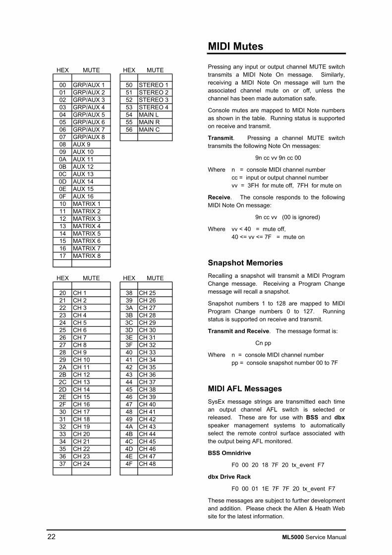
Pressing any input or output channel MUTE switch transmits a MIDI Note On message. Similarly, receiving a MIDI Note On message will turn the associated channel mute on or off, unless the channel has been made automation safe.
Console mutes are mapped to MIDI Note numbers as shown in the table. Running status is supported on receive and transmit.
Transmit. Pressing a channel MUTE switch transmits the following Note On messages:
9n cc vv 9n cc 00
Where n = console MIDI channel number cc = input or output channel number vv = 3FH for mute off, 7FH for mute on
Receive. The console responds to the following MIDI Note On message:
9n cc vv (00 is ignored)
Where vv < 40 = mute off, 40 <= vv <= 7F = mute on
Snapshot Memories Recalling a snapshot will transmit a MIDI Program Change message. Receiving a Program Change message will recall a snapshot.
Snapshot numbers 1 to 128 are mapped to MIDI Program Change numbers 0 to 127. Running status is supported on receive and transmit.
Transmit and Receive. The message format is:
Cn pp
Where n = console MIDI channel number pp = console snapshot number 00 to 7F
MIDI AFL Messages SysEx message strings are transmitted each time an output channel AFL switch is selected or released. These are for use with BSS and dbx speaker management systems to automatically select the remote control surface associated with the output being AFL monitored.
BSS Omnidrive
F0 00 20 18 7F 20 tx_event F7
dbx Drive Rack
F0 00 01 1E 7F 7F 20 tx_event F7
These messages are subject to further development and addition. Please check the Allen & Heath Web site for the latest information.
HEX MUTE HEX MUTE
00 GRP/AUX 1 50 STEREO 101 GRP/AUX 2 51 STEREO 202 GRP/AUX 3 52 STEREO 303 GRP/AUX 4 53 STEREO 404 GRP/AUX 5 54 MAIN L05 GRP/AUX 6 55 MAIN R06 GRP/AUX 7 56 MAIN C07 GRP/AUX 808 AUX 909 AUX 100A AUX 110B AUX 120C AUX 130D AUX 140E AUX 150F AUX 1610 MATRIX 111 MATRIX 212 MATRIX 313 MATRIX 414 MATRIX 515 MATRIX 616 MATRIX 717 MATRIX 8
HEX MUTE HEX MUTE
20 CH 1 38 CH 2521 CH 2 39 CH 2622 CH 3 3A CH 2723 CH 4 3B CH 2824 CH 5 3C CH 2925 CH 6 3D CH 3026 CH 7 3E CH 3127 CH 8 3F CH 3228 CH 9 40 CH 3329 CH 10 41 CH 342A CH 11 42 CH 352B CH 12 43 CH 362C CH 13 44 CH 372D CH 14 45 CH 382E CH 15 46 CH 392F CH 16 47 CH 4030 CH 17 48 CH 4131 CH 18 49 CH 4232 CH 19 4A CH 4333 CH 20 4B CH 4434 CH 21 4C CH 4535 CH 22 4D CH 4636 CH 23 4E CH 4737 CH 24 4F CH 48

ML5000 Service Manual 23
Archiving the Console Settings The console settings can be saved to an external device such as a MIDI sequencer or data archiver using the dump out facility. Saved settings can be loaded back into the console using dump in. This is ideal when you want to archive the settings to use at a later date, for example a re-run of a previous performance. You can also use the dump facility to program additional ML5000 consoles, for example when setting up duplicate shows or swapping consoles around. Simply link MIDI OUT from one to MIDI IN of the other and action the dump out facility.
Settings which are archived :
Current mute settings
Current Mute group assignments
Current VCA group assignments
Automation safes
Solo-in-Place safes
All snapshot memories
Settings which are not archived :
Current console operating mode
Current PAFL selection and settings
Store and auto-increment on/off
MIDI Dump Out Connect the console to a suitable MIDI archiving device. Set the same MIDI channel number on both. Check the rear switch is set to MIDI. Hold down SHIFT M9 and press STORE M4 . The console dumps the current settings and memory contents using a SysEx message string. During this time dPo is displayed. Note that this operation can take up to 10 seconds during which time the console mutes, assignment, SIP and P/AFL operations will be interrupted.
MIDI Dump In Connect the console to the MIDI archiving device. Set the same MIDI channel number on both. Check the rear switch is set to MIDI. Start the process using the MIDI archiver. The console current settings and memory contents are overwritten. During this time dPI is displayed. Note that this operation can take a while during which time the console mute, assignment, SIP and PAFL operations will be interrupted.
If you are using a MIDI sequencer to record the dump out data string then make sure you play it back at the same speed you recorded it. If you dump it back into the console faster than it was recorded some data may not load correctly.
MIDI Dump Message Format The format for dump out and in is identical. The dump data string is made up of multiple System Exclusive messages (known as packets) which contain the console information.
Transmit and Receive. The format for a single packet is as follows:
F0 <SysEx header> <packet type> <packet number> <data> <checksum> F7
<SysEx header> = 00 00 1A 50 07 VV vv nn
Where VV = software version number – unit vv = software version number – decimal nn = console MIDI channel number
<packet no.> = packet number from 0 to 127
<data> = block of console data (7-bit format)
<checksum> = checksum to allow error detection
MIDI Dump Errors If the console or connected equipment fails to respond to a MIDI dump then check:
• The MIDI cable is good and correctly plugged
• The same MIDI channel number is selected
• The rear panel switch is set to MIDI
• Try again
If a data error is detected during a dump out or in the console display will show an error message code:
Er1 Buffer overflow Er2 Packet out of sequence / missing
Er3 Checksum error / corrupt data Er4 Invalid packet length Er5 Input timeout Er6 Unsupported block type Er7 Invalid scene number Er8 Block size error
Allen & Heath ML Archiver The ML Archiver Windows™ utility for the PC can be downloaded from the Allen & Heath Internet site. This can be used to archive data to and from the PC via MIDI or RS232.
Check the Allen & Heath Web site for further details and loading instructions.

24 ML5000 Service Manual
Operating Software Technical Support
Operating Software Version Number The version number is briefly shown on the snapshot display on power up. Make sure the system amplifiers are muted or turned off before switching the console on or off. This example displays version 1.20
Loading New Operating Software Check the Allen & Heath Web site for the latest version of console software. New software is loaded from a PC via the RS232 port.
IMPORTANT ! The current console settings and snapshots may be lost when you load new operating software. If you wish to keep your settings and snapshot contents, first archive them using the dump out facility. Restore these after loading the new software by using dump in.
Download the software from the Allen & Heath Web site to your PC computer. Connect the PC RS232 port to the console RS232 port using a standard pin-to-pin (not null modem) 9-pin serial cable. Set the console rear panel switch to the RS232 position. Power up the console. The snapshot display should read UPd (update) as the console awaits data from the PC. Follow the instructions provided on the Web site for loading the new software into the console. When completed make sure you set the console rear panel switch back to the MIDI position.
Power Up and Power Down The console settings are saved when power is removed. On power up these settings are restored.
To Reset the Console Settings Hold down SHIFT and RECALL while turning on the console to reset all current settings. This does not affect the contents of the snapshot memories. The default settings are restored:
• Selects normal console operating mode
• Clears current P/AFL selections
• Clears all current Mute Group assignments
• Clears all current VCA Group assignments
• Clears all channel automation safes
• Restores the default SIP safes
• Enables the snapshot store function
• Turns off recall auto-increment
To Reset the Snapshot Memories Hold down SHIFT and STORE while turning the console on to clear all the snapshot memories. This does not affect the current console settings. For all snapshots:
• Clears all stored mutes
• Clears all stored VCA Group assignments
To reset all Settings and Memories Hold down SHIFT, RECALL and STORE together while turning the console on to clear all current settings and the memories.
Contacting Allen & Heath If you have any queries about the automation system please quote the console model, serial number and operating system version number in any communication with Allen & Heath or your appointed service agent. Technical support is available through your dealer or by visiting the Allen & Heath Internet Web site.
www.allen-heath.com
RECALL
(SHIFT)
STORE

ML5000 Service Manual 25
Servicing the Input Fader assembly
Before beginning any service work, remove all power to the unit and disconnect any signal cables where necessary. Ensure adequate lighting and use the correct tools.
Remove the numbered Ident strip by placing a flat headed screwdriver under one end and prizing it upwards. Remove the Ident strip by ‘peeling’ it from one end of the console to the other.
Remove the 3x 6Bx3/8 Countersunk Pozi Zinc Screws from the top of the fader panel (A) and the 3x 6Bx3/8 Flange Headed Pozi Black Screws from the bottom of the fader panel, taking care to retain the plastic washers (B) (see fig.1). Carefully tilt the fader panel assembly out from the console and remove all connecting IDC wireforms. The fader panel assembly can now be removed from the console.
3) Flip the fader panel over and remove the 2x 4ABx5/16 Countersunk Pozi Black Screws (D) from the Fader Slave PCB (see fig.2)
D
fig.2
fig.1
A
C
B
26 ML5000 Service Manual
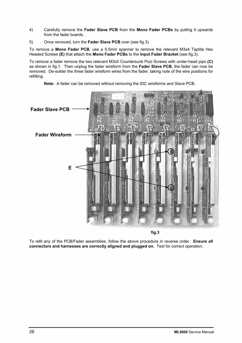
4) Carefully remove the Fader Slave PCB from the Mono Fader PCBs by pulling it upwards
from the fader boards.
5) Once removed, turn the Fader Slave PCB over (see fig.3)
To remove a Mono Fader PCB, use a 5.5mm spanner to remove the relevant M3x4 Taptite Hex Headed Screws (E) that attach the Mono Fader PCBs to the Input Fader Bracket (see fig.3).
To remove a fader remove the two relevant M3x5 Countersunk Pozi Screws with under-head pips (C) as shown in fig.1. Then unplug the fader wireform from the Fader Slave PCB, the fader can now be removed. De-solder the three fader wireform wires from the fader, taking note of the wire positions for refitting.
Note: A fader can be removed without removing the IDC wireforms and Slave PCB.
To refit any of the PCB/Fader assemblies, follow the above procedure in reverse order. Ensure all connectors and harnesses are correctly aligned and plugged on. Test for correct operation.
fig.3
Fader Slave PCB
Fader Wireform
E

ML5000 Service Manual 27
Servicing the Master Fader assembly
Before beginning any service work, remove all power to the unit and disconnect any signal cables where necessary. Ensure adequate lighting and use the correct tools.
Remove the numbered Ident strip by placing a flat headed screwdriver under one end and prizing it upwards. Remove the Ident strip by ‘peeling’ it from one end of the console to the other.
Remove the 5x 6Bx3/8 Countersunk Pozi Zinc Screws from the top of the fader panel (F) and the 5x 6Bx3/8 Flange Headed Pozi Black Screws from the bottom of the fader panel, taking care to retain the plastic washers (G) (see fig.4). Carefully tilt the fader panel assembly out from the console and remove all connecting IDC wireforms. The fader panel assembly can now be removed from the console.
Flip the fader panel over to reveal the PCB assemblies (see fig.5).
Stereo Fader PCBs Master Fader Centre PCB
Master Fader L/R PCBs
Mute Group PCB
VCA Master Fader PCBs
Control Panel PCB
Stereo Slave PCB
VCA Master Slave PCB
fig.5
fig.4
G
H
F
28 ML5000 Service Manual
The Stereo Slave PCB must be removed before the following PCBs can be removed; Mono Fader, Master Fader Centre, Master Fader L/R & Control Panel.
1) Cut the 2x Cable ties attaching the Stereo Slave PCB onto the Mono Fader & Control Panel PCBs.
2) Carefully remove the Stereo Slave PCB by pulling it upwards.
3) Once removed, turn the Stereo Slave PCB over.
4) To remove a PCB, use a 5.5mm spanner to remove the relevant M3x4 Taptite Hex Headed Screws that attach the PCBs to the Master Fader bracket.
5) To remove a fader, remove the two relevant M3x5 Countersunk Pozi Screws with underhead pips (H) as shown in fig.4. Then unplug the fader wireform from the Stereo Slave PCB, the fader can now be removed. De-solder the three fader wireform wires from the fader, taking note of the wire positions for refitting.
6) Removal of the ‘H’ shaped Control Panel PCB can only be achieved once the vertical section of PCB has been removed. Once the vertical section has been removed, remove the 2x M3x6mm Pan Pozi Black screws attaching the ‘H’ shaped Control Panel PCB to the fader bracket. The ‘H’ shaped Control Panel PCB can then be removed.
10) To remove the Mute Group PCB, use a 5.5mm spanner to remove the two screws attaching the PCB to the fader bracket.
The VCA Master Slave PCB must be removed before the Master Fader PCBs can be removed.
11) Cut the 2x Cable ties attaching the VCA Master Slave PCB onto the Master Fader PCBs.
12) Remove the 15way Flexi cable running between the VCA Master Slave PCB and the Mute Group PCB.
13) Carefully remove the VCA Master Slave PCB by pulling it upwards.
14) Once removed, turn the VCA Master Slave PCB over.
15) To remove a PCB, use a 5.5mm spanner to remove the relevant M3x4 Taptite Hex Headed Screws that attach the PCBs to the Master Fader Bracket.
16) To remove a fader, remove the two relevant M3x5 Countersunk Pozi Screws (H) from the Master Fader front panel (see fig.4). Unplug the fader wireform from the Stereo Slave PCB, the fader can now be removed. De-solder the three Fader wireform wires from the fader, taking note of the wire positions for refitting.
Note: A fader can be removed without removing the IDC wireforms and Slave PCB.
17) To refit any of the PCB assemblies, follow the above procedure in reverse order. Make sure all harnesses are aligned and plugged on. Test for correct operation.
ML5000 Service Manual 29
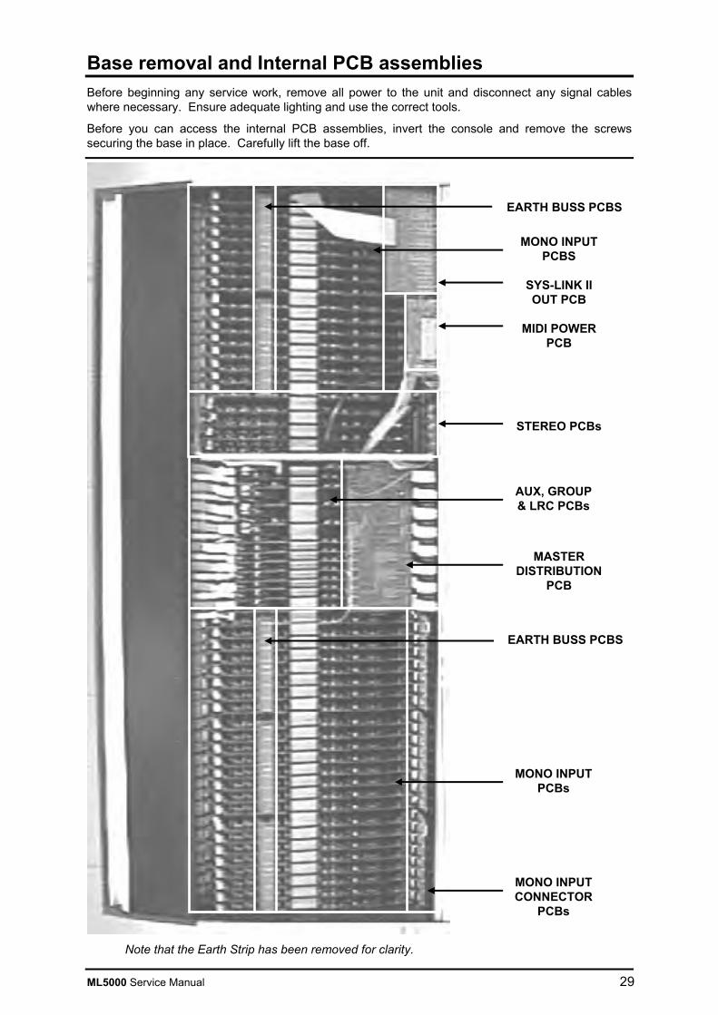
Base removal and Internal PCB assemblies Before beginning any service work, remove all power to the unit and disconnect any signal cables where necessary. Ensure adequate lighting and use the correct tools.
Before you can access the internal PCB assemblies, invert the console and remove the screws securing the base in place. Carefully lift the base off.
Note that the Earth Strip has been removed for clarity.
MONO INPUT CONNECTOR
PCBs
MONO INPUT PCBs
AUX, GROUP & LRC PCBs
MASTER DISTRIBUTION
PCB
STEREO PCBs
MIDI POWER PCB
SYS-LINK II OUT PCB
MONO INPUT PCBS
EARTH BUSS PCBS
EARTH BUSS PCBS

30 ML5000 Service Manual
Removing a Mono Input PCB assembly
Before beginning any service work, remove all power to the unit and disconnect any signal cables where necessary. Ensure adequate lighting and use the correct tools.
1) Remove the screws attaching the relevant Earth Strip running the length of the Mono section (see fig.6, right hand section only shown) then lift away the Earth Strip.
2) Carefully detach the 50way IDC wireform from the Mono Input PCBs and the SYS-LINK II Input PCB as far as the relevant Mono Input PCB. Note: There are two different 50way IDC wireforms on either side of the Master section. Remove the relevant IDC wireform according to the side on which the particular Mono Input PCB lies.
3) Remove all the knob and switch caps from the required Mono Input PCB, then remove the pot nuts underneath using an 11mm nutdriver.
4) The required Mono Input PCB can now be removed from the console.
5) To refit a Mono Input PCB assembly, follow the above procedure in reverse order. Make sure all harnesses are correctly aligned and plugged on. Test for correct operation.
fig.6
SYS-LINK II PCB
Earth Strip
50 way IDC
wireform
ML5000 Service Manual 31
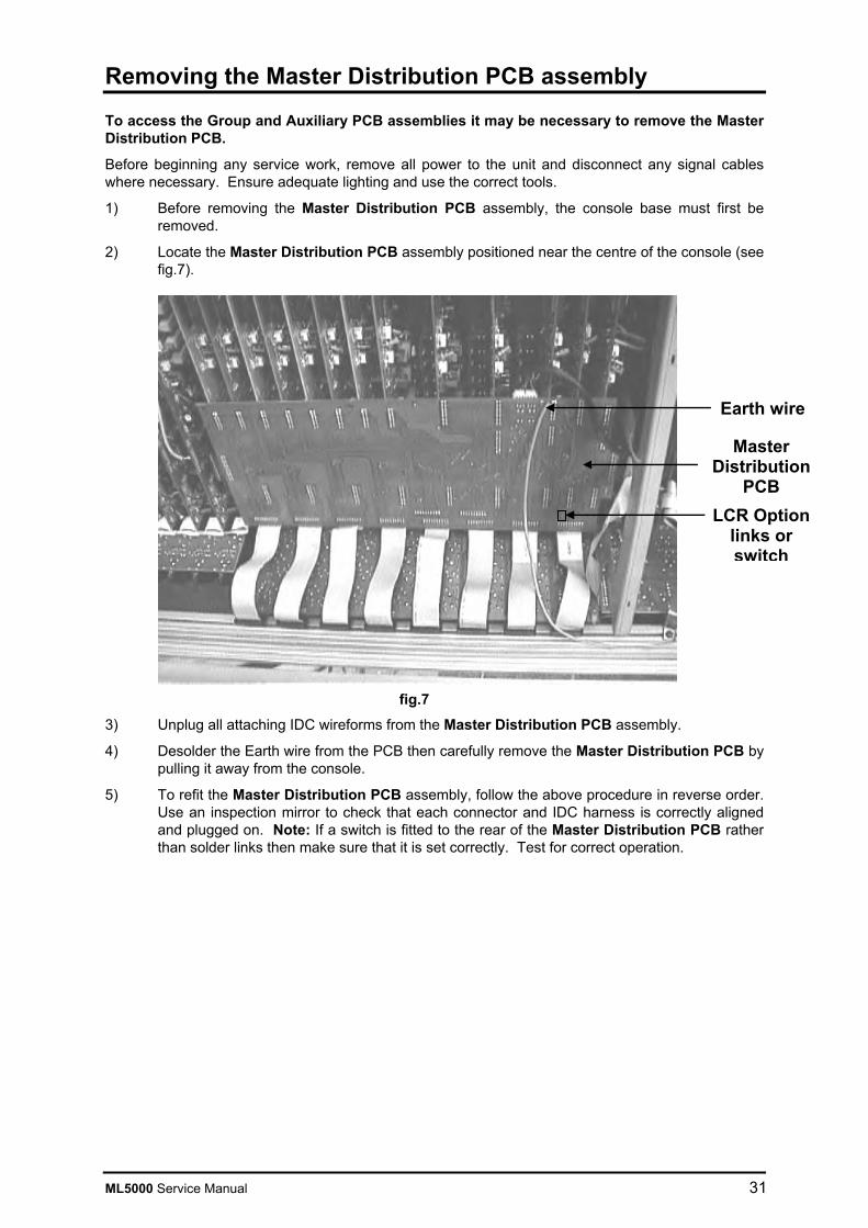
Removing the Master Distribution PCB assembly
To access the Group and Auxiliary PCB assemblies it may be necessary to remove the Master Distribution PCB.
Before beginning any service work, remove all power to the unit and disconnect any signal cables where necessary. Ensure adequate lighting and use the correct tools.
1) Before removing the Master Distribution PCB assembly, the console base must first be removed.
2) Locate the Master Distribution PCB assembly positioned near the centre of the console (see fig.7).
3) Unplug all attaching IDC wireforms from the Master Distribution PCB assembly.
4) Desolder the Earth wire from the PCB then carefully remove the Master Distribution PCB by pulling it away from the console.
5) To refit the Master Distribution PCB assembly, follow the above procedure in reverse order. Use an inspection mirror to check that each connector and IDC harness is correctly aligned and plugged on. Note: If a switch is fitted to the rear of the Master Distribution PCB rather than solder links then make sure that it is set correctly. Test for correct operation.
fig.7
Master Distribution
PCB
Earth wire
LCR Option links or switch

32 ML5000 Service Manual
Servicing the Meterbridge Assembly
Before beginning any service work, remove all power to the unit. Ensure adequate lighting and use the correct tools.
1) Remove all the plastic snap-in rivets along the face of the meter panel with your fingernails or other non-abrasive tool.
2) With a person standing at either end of the console, each using a small, thin screwdriver, place the screwdriver through each of the endmost bottom rivet holes (see fig 8). Raise the meter panel up with the screwdrivers so that the bottom becomes free of the extrusion.
3) The complete meter panel assembly can now be removed from the meter pod extrusion by pulling it away from the extrusion, bottom first (see fig.9), allowing access to the Meter PCB assemblies. Remove the two attaching IDC harnesses.
fig.8
fig.9
ML5000 Service Manual 33
Servicing the MPS14 Power Supply
Cleaning and Replacing the fan filters.
At regular intervals, it is recommended that the foam fan filters are cleaned or replaced to ensure efficient operation of the power unit. Failure to do so may reduce the efficiency or even damage the power unit.
To remove the fan filters, switch off and disconnect all power to the MPS14. Remove the rack ears and place to one side. Remove the cover fixing screws and cover and place to one side.
The foam fan filters can now be removed by simply sliding out of the slots.
Either clean or fit new filters depending on their condition.
Replace the filters and reassemble the power unit. Check the fans are running unobstructed before completely re-installing.
Replacing the mains fuse
The AC mains fuse is located on the rear of the MPS14 unit next to the AC mains connector. In the event of a mains surge or under-rated fuse value, the mains input fuse will rupture. Switch off the power supply and remove the mains lead plug from the “MAINS INPUT” socket on the rear of the unit.
Check the fuse and replace if necessary.
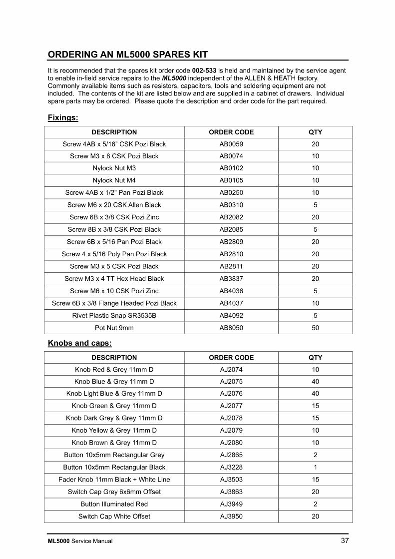
TO AVOID THE RISK OF FIRE REPLACE FUSE WITH THE CORRECT TYPE ONLY, AS INDICATED ON THE UNIT
AC~ mains input voltage Fuse type
100V – 230V ± 10% T 5A 250V 20mm
In the event of repeated failure of the mains fuse, consult the local dealer from where the unit was purchased.

34 ML5000 Service Manual
ORDERING A CONSOLE To order a new console please specify the model number and AC mains voltage for the Power Supply.
MODEL DESCRIPTION ORDER CODE
ML5000-32 32 Mono + 4 Stereo Input Channels ML5000-32
ML5000-40 40 Mono + 4 Stereo Input Channels ML5000-40
ML5000-48 48 Mono + 4 Stereo Input Channels ML5000-48
MPS14 Power Supply for ML5000 MPS14/*
* - Specify the voltage and mains plug requirement for your area.
ORDERING AN ACCESSORY To order an option please specify the model number required.
MODEL DESCRIPTION ORDER CODE
SIDECAR EXPANDER OPTIONAL 24 MONO INPUT SIDECAR ML5000-24SC
DC POWER LEAD 2.9 METRE DC POWER LEAD 002-583
DC COMBINER LEAD 0.75 METRE DC COMBINER LEAD 002-584
SYS-LINK CABLE 2.8 METRE 37 WAY AUDIO CABLE 002-617
LOGIC CABLE 2.9 METRE 9 WAY LOGIC CABLE AL4155
GOOSENECK LAMP 18” GOOSENECK LAMP AL4061
32 CHANNEL DUSTCOVER 32 CHANNEL VINYL DUSTCOVER AP4121
40 CHANNEL DUSTCOVER 40 CHANNEL VINYL DUSTCOVER AP4122
48 CHANNEL DUSTCOVER 48 CHANNEL VINYL DUSTCOVER AP4123
SIDE-CAR DUSTCOVER SIDECAR VINYL DUSTCOVER AP4234
MANUALS AND SUPPORT DOCUMENTATION
MODEL DESCRIPTION ORDER CODE
ML5000 User Guide AP3736
ML5000 SIDECAR User Guide AP4124
MPS14 POWER SUPPLY User Guide AP3898
SERVICE TOOLS The tools required to service the ML5000 are standard to an electronics service workshop and are easily obtainable. The following items are necessary for disassembly and service access:
TOOL USE ORDER CODE
4mm Hexagon (Allen) key M6 side trim AT0033
1-point Crosshead screwdriver M3, 4AB AT0004
2-point Crosshead screwdriver M4, 6AB, 8B AT0002
11mm AF Nutdriver Potentiometer and headphone nuts
12mm Nutdriver Jack nuts
1.27mm Hexagon (Allen) key PSU DC Leads AT4142
2.5MM hexagon (Allen) key M4 Sidetrim
5.5mm AF Spanner Fader PCB M3 Hex
5mm Nutspinner D-Type Screws

ML5000 Service Manual 35
ORDERING AN ASSEMBLY The following assemblies for the ML5000 are supplied fully tested. Please quote the description and order code for the part required.
Printed circuit board (PCB) assemblies:
DESCRIPTION ORDER CODE
Mono Input PCB assembly 002-529
Stereo Input PCB assembly 002-564
Group 1, 3, 5, 7 PCB assembly 002-552
Group PCB assembly 002-553
Group 2, 4, 6, 8 PCB assembly 002-554
Aux 10 PCB assembly 002-545
Aux 12 PCB assembly 002-546
Aux 14 PCB assembly 002-547
Aux 16 PCB assembly 002-548
Master Distribution PCB assembly 002-556
LCR Mix PCB assembly 002-544
Mono Fader PCB assembly 002-530
Master Fader Centre PCB assembly 002-589
Master Fader L/R PCB assembly 002-588
Master Fader VCA PCB assembly 002-557
Mute Group PCB assembly 002-563
Control Panel PCB assembly 002-549
Fader Slave PCB assembly 002-551
Stereo Slave PCB assembly 002-566
VCA Master Slave PCB assembly 002-567
Aux Master Slave PCB assembly 002-543
CPU PCB assembly 002-550
Mono Connector PCB assembly 002-560
Stereo LRC Connector PCB assembly 002-565
Master Connector PCB assembly 002-555
MIDI Power PCB assembly 002-575
Sidecar MIDI Power PCB assembly 002-598
SYS-LINK 2 In PCB assembly 002-587
SYS-LINK 2 Out PCB assembly 002-596
Meter 1-8 PCB assembly 002-558
Meter 9-16 PCB assembly 002-591
Meter Master PCB assembly 002-559
Meter Ledbar PCB assembly 002-590

36 ML5000 Service Manual
IDC connector harnesses:
DESCRIPTION ORDER CODE 10 way GRAUX harness AL4029
10 way Input harness AL4028
10 way LRC to Fader harness AL4077
10 way MIDI harness AL4032
16 way GRAUX harness AL4030
20 way Master Connector harness AL4027
20 way Meter harness AL4021
26 way CPU Power harness AL4033
26 way LRC Connector harness AL4031
26 way Distribution harness AL4020
26 way Slave A harness AL4022
26 way Slave B harness AL4023
26 way Slave C harness AL4024
26 way Slave D harness AL4025
34 way Master harness AL4026
Sidecar harness AL4067
ML5-32 Left harness AL3964
ML5-32/40 Right harness AL3967
ML5-40/48 Left harness AL3834
ML5-48 Right harness AL3835
THE CHASSIS TRIM
DESCRIPTION ORDER CODE ML5000 (all formats) Left & Right Chassis side trims AA3773-L/R
Left & Right Moulded side trims AA3781-L/R
Write-on strip 10’ AK0327
Ident strip Master Rear AK3788
Ident strip Master AK3833
Ident strip 1-24 AK3789
Ident strip 1-24 Rear AK3790
Ident strip 25-48 AK3795
Ident strip 25-48 Rear AK3796
ML5000 Service Manual 37
ORDERING AN ML5000 SPARES KIT It is recommended that the spares kit order code 002-533 is held and maintained by the service agent to enable in-field service repairs to the ML5000 independent of the ALLEN & HEATH factory. Commonly available items such as resistors, capacitors, tools and soldering equipment are not included. The contents of the kit are listed below and are supplied in a cabinet of drawers. Individual spare parts may be ordered. Please quote the description and order code for the part required.
Fixings:
DESCRIPTION ORDER CODE QTY
Screw 4AB x 5/16” CSK Pozi Black AB0059 20
Screw M3 x 8 CSK Pozi Black AB0074 10
Nylock Nut M3 AB0102 10
Nylock Nut M4 AB0105 10
Screw 4AB x 1/2" Pan Pozi Black AB0250 10
Screw M6 x 20 CSK Allen Black AB0310 5
Screw 6B x 3/8 CSK Pozi Zinc AB2082 20
Screw 8B x 3/8 CSK Pozi Black AB2085 5
Screw 6B x 5/16 Pan Pozi Black AB2809 20
Screw 4 x 5/16 Poly Pan Pozi Black AB2810 20
Screw M3 x 5 CSK Pozi Black AB2811 20
Screw M3 x 4 TT Hex Head Black AB3837 20
Screw M6 x 10 CSK Pozi Zinc AB4036 5
Screw 6B x 3/8 Flange Headed Pozi Black AB4037 10
Rivet Plastic Snap SR3535B AB4092 5
Pot Nut 9mm AB8050 50
Knobs and caps:
DESCRIPTION ORDER CODE QTY
Knob Red & Grey 11mm D AJ2074 10
Knob Blue & Grey 11mm D AJ2075 40
Knob Light Blue & Grey 11mm D AJ2076 40
Knob Green & Grey 11mm D AJ2077 15
Knob Dark Grey & Grey 11mm D AJ2078 15
Knob Yellow & Grey 11mm D AJ2079 10
Knob Brown & Grey 11mm D AJ2080 10
Button 10x5mm Rectangular Grey AJ2865 2
Button 10x5mm Rectangular Black AJ3228 1
Fader Knob 11mm Black + White Line AJ3503 15
Switch Cap Grey 6x6mm Offset AJ3863 20
Button Illuminated Red AJ3949 2
Switch Cap White Offset AJ3950 20

38 ML5000 Service Manual
Button 6x6mm Square White AJ3951 10
Button 6x6mm Square Light Grey AJ3952 5
Button 6x6mm Square Red AJ3953 10
Button 6x6mm Square Black AJ3954 5
Button 8mm Round Light Grey AJ3955 10
Fader Knob 11mm White+Black Line AJ8078 10
Fader Knob 11mm Red+Black Line AJ8079 10
Fader Knob 11mm Yellow+Black Line AJ8080 5
Fader Knob 11mm Blue+Black Line AJ8081 10
Button Illuminated White AJ8107 10
Faders, Potentiometers, Switches and connectors:
Pot 10KC x 2 (103C 14mm wide) AI0150 3
Pot 20KK (203K 11mm wide) AI8003 5
Pot 20KB C/D (203B 11mm wide) AI8004 5
Pot 200KC x 2 (204C 11mm wide) AI8005 5
Pot 20KB x 2 centre click (14mm wide) AI8006 5
Pot 20KK x 2 (203K 14mm wide) AI8007 10
Pot 10KAC x2 (103AC 14mm wide) AI8008 10
Pot 200KC x 2 (204C 14mm wide) AI8009 5
Fader 10KSPE 100mm AI8109 3
Pot 5K (502RD 11mm wide) AI8111 5
Fader 10KB 100mm AI8175 10
Fader 10KA 60mm AI8176 5
Switch 2PCO Latching 90 Deg AL0162 10
Jack Socket Headphone AL0328 1
Switch 4PCO Latching AL0333 15
Switch 2PCO Momentary AL0374 10
XLR 3 Pin Female Vertical PCB Mount AL2410 5
XLR 3 Pin Male Vertical PCB Mount AL2411 5
Switch Slide MINI SPDT PCB AL3081 1
Jack Socket ¼” Stereo Unswitched AL3407 20
Jack Socket ¼” Stereo Switched AL3410 20
LEDs and Semiconductors:
Transistor BC549 NPN AE0020 5
IC TLO72 Op-Amp AE0046 10
Transistor J111N FET T092 AE0083 10
LED 3mm T1 Yellow AE0084 10
LED 3mm T1 Green AE0085 10
LED 3mm T1 Red AE0086 10

ML5000 Service Manual 39
IC CMOS 4053B AE0117 10
IC CMOS 4051B AE0118 1
IC NE5532 Op-Amp AE0221 10
IC 6N136 Opto-Isolator AE0222 1
IC TTL 74LSOO AE0243 1
IC Opto-Isolator 4N35 AE0266 2
IC 7805 Regulator AE0308 3
IC SSM2018P VCA AE0315 5
IC RS232 HIN202CP AE2742 1
IC CMOS 74HC165 AE2749 3
IC CMOS 74HC4094N AE2755 5
IC Comparator LM393N AE2818 5
Transistor BC556B PNP AE3001 5
Crystal 14MHz AE3007 1
LED Square Red AE3489 5
LED Square Green AE3490 10
LED Square Yellow AE3491 5
Transistor Mosfet BSS138 AE3498 1
IC LA6515 Power Op-Amp AE3707 3
IC CMOS 74HCT02 AE3988 1
IC SN75176BP Buffer AE3989 1
LED Rect. Red 5 x 2.5mm AE4015 3
LED Rect. Yellow 5 x 2.5mm AE4016 3
LED Rect. Green 5 x 2.5mm AE4017 3
LED T1 3mm Blue AE4041 3
Transistor 2SB737 PNP AE8069 10
Miscellaneous:
Preset 10K Carbon Horizontal Mini AC0250 5
Preset 470K Carbon Horizontal Adjust AC4012 5
Meter bulb AD0013 5
VU Meter + 8V Bulb AD3321 2
Flex Cable 12 Way 90mm AH2228 5
Flex Cable 15 Way 90mm AH4091 3
Battery 2.4V 70mAh NICAD AP3334 1
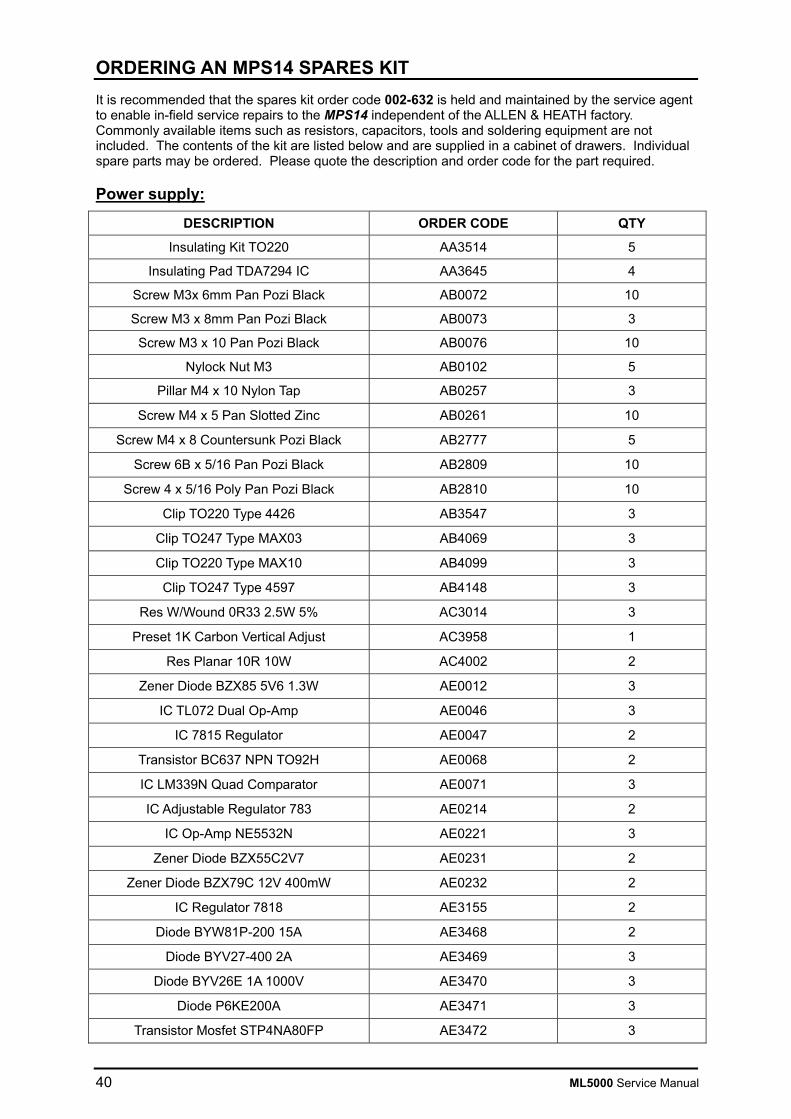
40 ML5000 Service Manual
ORDERING AN MPS14 SPARES KIT It is recommended that the spares kit order code 002-632 is held and maintained by the service agent to enable in-field service repairs to the MPS14 independent of the ALLEN & HEATH factory. Commonly available items such as resistors, capacitors, tools and soldering equipment are not included. The contents of the kit are listed below and are supplied in a cabinet of drawers. Individual spare parts may be ordered. Please quote the description and order code for the part required.
Power supply:
DESCRIPTION ORDER CODE QTY
Insulating Kit TO220 AA3514 5
Insulating Pad TDA7294 IC AA3645 4
Screw M3x 6mm Pan Pozi Black AB0072 10
Screw M3 x 8mm Pan Pozi Black AB0073 3
Screw M3 x 10 Pan Pozi Black AB0076 10
Nylock Nut M3 AB0102 5
Pillar M4 x 10 Nylon Tap AB0257 3
Screw M4 x 5 Pan Slotted Zinc AB0261 10
Screw M4 x 8 Countersunk Pozi Black AB2777 5
Screw 6B x 5/16 Pan Pozi Black AB2809 10
Screw 4 x 5/16 Poly Pan Pozi Black AB2810 10
Clip TO220 Type 4426 AB3547 3
Clip TO247 Type MAX03 AB4069 3
Clip TO220 Type MAX10 AB4099 3
Clip TO247 Type 4597 AB4148 3
Res W/Wound 0R33 2.5W 5% AC3014 3
Preset 1K Carbon Vertical Adjust AC3958 1
Res Planar 10R 10W AC4002 2
Zener Diode BZX85 5V6 1.3W AE0012 3
IC TL072 Dual Op-Amp AE0046 3
IC 7815 Regulator AE0047 2
Transistor BC637 NPN TO92H AE0068 2
IC LM339N Quad Comparator AE0071 3
IC Adjustable Regulator 783 AE0214 2
IC Op-Amp NE5532N AE0221 3
Zener Diode BZX55C2V7 AE0231 2
Zener Diode BZX79C 12V 400mW AE0232 2
IC Regulator 7818 AE3155 2
Diode BYW81P-200 15A AE3468 2
Diode BYV27-400 2A AE3469 3
Diode BYV26E 1A 1000V AE3470 3
Diode P6KE200A AE3471 3
Transistor Mosfet STP4NA80FP AE3472 3
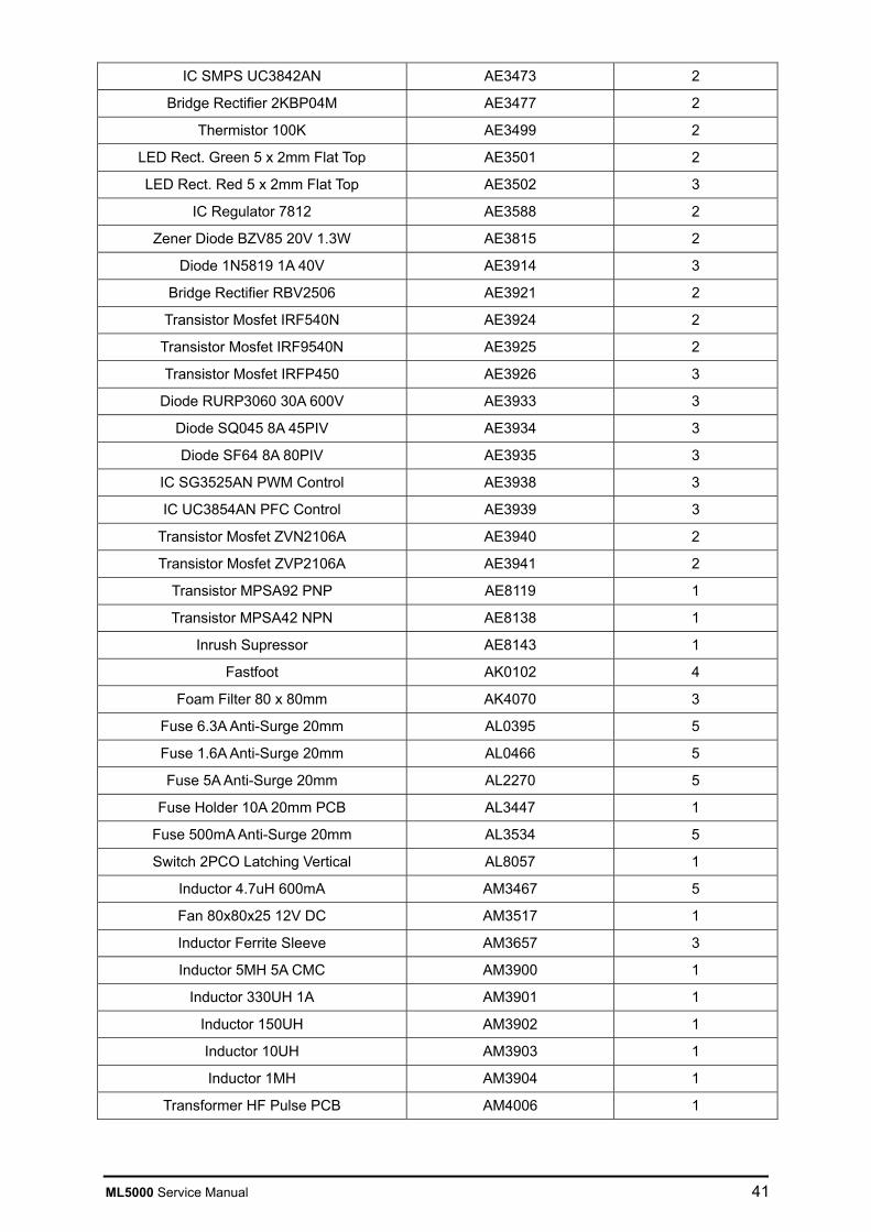
ML5000 Service Manual 41
IC SMPS UC3842AN AE3473 2
Bridge Rectifier 2KBP04M AE3477 2
Thermistor 100K AE3499 2
LED Rect. Green 5 x 2mm Flat Top AE3501 2
LED Rect. Red 5 x 2mm Flat Top AE3502 3
IC Regulator 7812 AE3588 2
Zener Diode BZV85 20V 1.3W AE3815 2
Diode 1N5819 1A 40V AE3914 3
Bridge Rectifier RBV2506 AE3921 2
Transistor Mosfet IRF540N AE3924 2
Transistor Mosfet IRF9540N AE3925 2
Transistor Mosfet IRFP450 AE3926 3
Diode RURP3060 30A 600V AE3933 3
Diode SQ045 8A 45PIV AE3934 3
Diode SF64 8A 80PIV AE3935 3
IC SG3525AN PWM Control AE3938 3
IC UC3854AN PFC Control AE3939 3
Transistor Mosfet ZVN2106A AE3940 2
Transistor Mosfet ZVP2106A AE3941 2
Transistor MPSA92 PNP AE8119 1
Transistor MPSA42 NPN AE8138 1
Inrush Supressor AE8143 1
Fastfoot AK0102 4
Foam Filter 80 x 80mm AK4070 3
Fuse 6.3A Anti-Surge 20mm AL0395 5
Fuse 1.6A Anti-Surge 20mm AL0466 5
Fuse 5A Anti-Surge 20mm AL2270 5
Fuse Holder 10A 20mm PCB AL3447 1
Fuse 500mA Anti-Surge 20mm AL3534 5
Switch 2PCO Latching Vertical AL8057 1
Inductor 4.7uH 600mA AM3467 5
Fan 80x80x25 12V DC AM3517 1
Inductor Ferrite Sleeve AM3657 3
Inductor 5MH 5A CMC AM3900 1
Inductor 330UH 1A AM3901 1
Inductor 150UH AM3902 1
Inductor 10UH AM3903 1
Inductor 1MH AM3904 1
Transformer HF Pulse PCB AM4006 1

42 ML5000 Service Manual
Channel Cue Sheet
+48V
- 10 10
GAIN
20
4060
30
20Hz 400
10050 200
O
PAD
LR C
=
L R
=
PAN
Q
-15 +15
-15 +15
-15 +15
7kHz
3k
2kHz 20kHz
10k
HF
100Hz
50
20Hz 200Hz
150
LF
100Hz60
20Hz 1kHz
120
30 250
LM
Q
-15 +15
2kHz1k
400Hz 20kHz
3k
HM
EQ IN
HPF
OO +6
OO +6
STEREO9LEV 9-10
10PAN
OO +6
OO +6
STEREOLEV 11-12
12PAN
OO +6
OO +6
STEREOLEV 13-14
14PAN
OO +6
OO +6
STEREOLEV 15-16
16PAN
11
13
15
MAINMIX
LCRBLEND
+
40
0.6 2.5
1.2
500 5k
0.6 2.5
1.2
PRE
PRE
PRE
PRE
20dB
1
OO +6
AUX
2
OO +6
AUX
3
OO +6
AUX
4
OO +6
AUX
5
OO +6
AUX
6
OO +6
AUX
7
OO +6
AUX
8
OO +6
AUX
PRE
PRE
PRE
PRE
PRE
PRE
PRE
PRE
5
7
GROUP
8VCA
6
4
3
2
1
OO
30
5
0
PAFL
MUTE
PK
-6
SIG
+6
0
SAFE/EDIT
10
5
40
10
20
5
7
GROUP
8VCA
6
4
3
2
1
OO
30
5
0
PAFL
MUTE
PK
-6
SIG
+6
0
SAFE/EDIT
10
5
40
10
20
5
7
GROUP
8VCA
6
4
3
2
1
OO
30
5
0
PAFL
MUTE
PK
-6
SIG
+6
0
SAFE/EDIT
10
5
40
10
20
5
7
GROUP
8VCA
6
4
3
2
1
OO
30
5
0
PAFL
MUTE
PK
-6
SIG
+6
0
SAFE/EDIT
10
5
40
10
20
5
7
GROUP
8VCA
6
4
3
2
1
OO
30
5
0
PAFL
MUTE
PK
-6
SIG
+6
0
SAFE/EDIT
10
5
40
10
20
5
7
GROUP
8VCA
6
4
3
2
1
OO
30
5
0
PAFL
MUTE
PK
-6
SIG
+6
0
SAFE/EDIT
10
5
40
10
20
5
7
GROUP
8VCA
6
4
3
2
1
OO
30
5
0
PAFL
MUTE
PK
-6
SIG
+6
0
SAFE/EDIT
10
5
40
10
20
5
7
GROUP
8VCA
6
4
3
2
1
OO
30
5
0
PAFL
MUTE
PK
-6
SIG
+6
0
SAFE/EDIT
10
5
40
10
20

ML5000 Service Manual 43
Master Cue Sheet
0
0
0
0
0
0
0
0

44 ML5000 Service Manual
Service Notes:
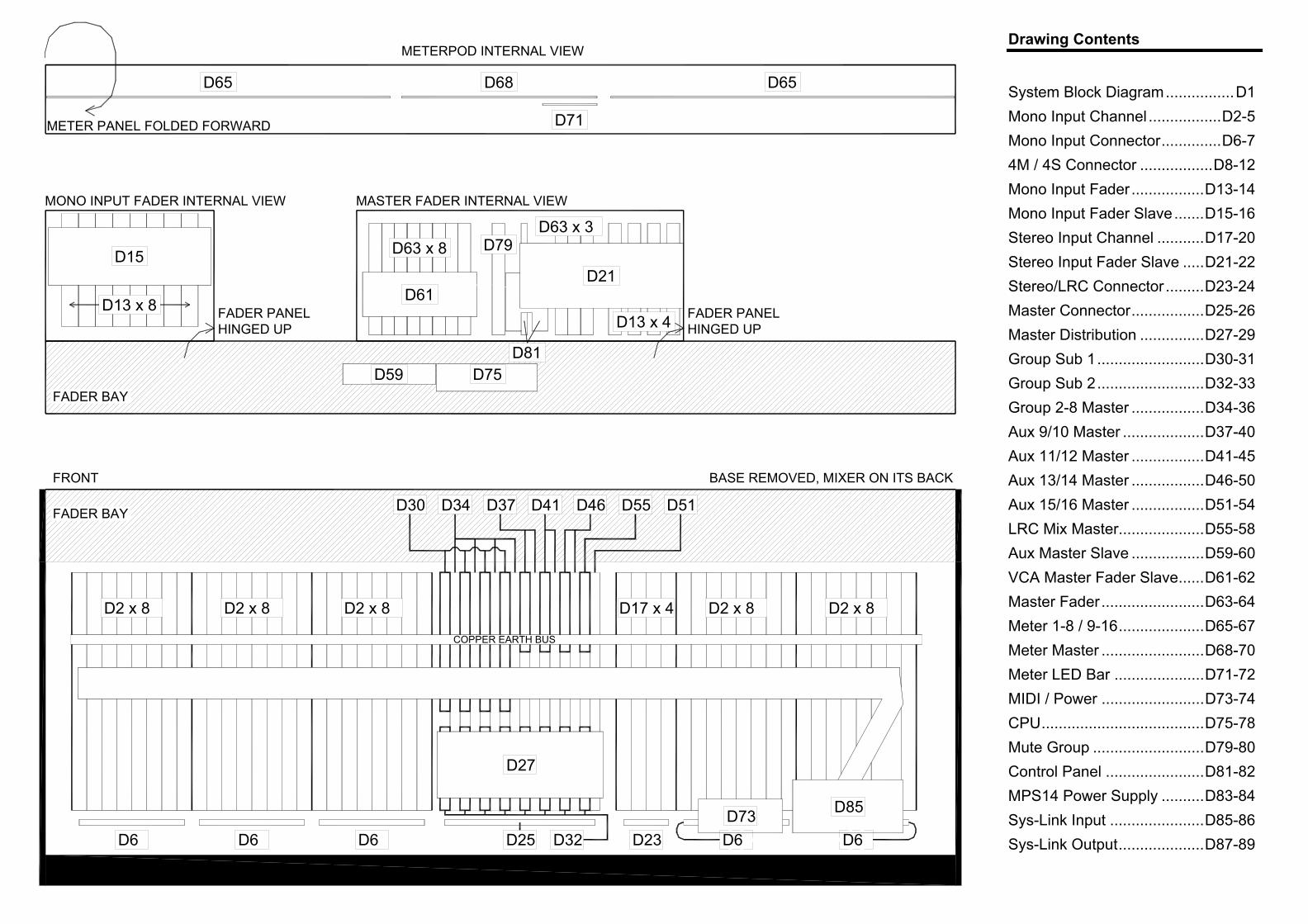
Drawing Contents
System Block Diagram................D1 Mono Input Channel .................D2-5 Mono Input Connector..............D6-7 4M / 4S Connector .................D8-12 Mono Input Fader.................D13-14 Mono Input Fader Slave.......D15-16 Stereo Input Channel ...........D17-20 Stereo Input Fader Slave .....D21-22 Stereo/LRC Connector .........D23-24 Master Connector.................D25-26 Master Distribution ...............D27-29 Group Sub 1.........................D30-31 Group Sub 2.........................D32-33 Group 2-8 Master .................D34-36 Aux 9/10 Master ...................D37-40 Aux 11/12 Master .................D41-45 Aux 13/14 Master .................D46-50 Aux 15/16 Master .................D51-54 LRC Mix Master....................D55-58 Aux Master Slave .................D59-60 VCA Master Fader Slave......D61-62 Master Fader........................D63-64 Meter 1-8 / 9-16....................D65-67 Meter Master ........................D68-70 Meter LED Bar .....................D71-72 MIDI / Power ........................D73-74 CPU......................................D75-78 Mute Group ..........................D79-80 Control Panel .......................D81-82 MPS14 Power Supply ..........D83-84 Sys-Link Input ......................D85-86 Sys-Link Output....................D87-89
METERPOD INTERNAL VIEW
D65
METER PANEL FOLDED FORWARD
D68
D71
D65
D59 D75
D2 x 8 D2 x 8 D2 x 8 D2 x 8 D2 x 8
D27
D6 D6 D6 D6D6
D85D73D23D25
D17 x 4
D30 D34 D37 D41 D46 D55
D32
FADER BAY
BASE REMOVED, MIXER ON ITS BACKFRONT
COPPER EARTH BUS
D51
FADER BAY
D15
D13 x 8
MASTER FADER INTERNAL VIEW
FADER PANELHINGED UP
MONO INPUT FADER INTERNAL VIEW
FADER PANELHINGED UP
D63 x 8
D61
D79D63 x 3
D21
D13 x 4
D81
VCA Master

+-
INPUT
GAIN+48V
ML5000 BLOCK DIAGRAM
PAD HPF IN SEND
LF LM HM HF
EQ IN
FREQ4 BAND EQUALISERFILTER
METER
+-
RETURNINSERT
POST-EQ
PRE-EQ
PAN BLENDMAINMIX
L R LR C
PRE-INSERT
+
+
L
R
C
PEAK
LCR+
PRE-FADEPOST-FADE
ODDEVEN
PRE
GRP PAN ON
AUX1
GRP1
POST-TRIM
PRE-FADE
POST-FADEDIRECT OUT
(AUX1 ONLY)
PO
ST
AU
X1
AU
X1G
RP
1POST-MUTE
PRE-FADE AUXOPTION LINKS
MONO
STEREO
OPTION LINKSDIRECT OUT
PFL
L AFL
R AFL
L MIXR MIXC MIX
GRP2
AU
X 2
PO
ST
AU
X2
GR
P2
AUX2
PRE
SET MASTER mode SWITCHFOR EITHER AUX OR GROUP
MONO CHANNEL
MUTE
FADER PAFL
MUTE GROUPS
VCA GROUPS
PAFL LOGIC
GRP
GRP/AUX 3 TO 8SAME AS 1,2 SHOWN
VCA
J5
J4
J6
J9
J7 J8J3
J2
J1
MIXSEND
+-
RETURNINSERT
MUTEFADER
MUTE GROUPS
mode
METERPEAK
L AFL
R AFL
AFLAFL LOGIC
PANBLEND
MAINMIX
L R LR C
LCR+
L MIXR MIXC MIX
TB ENABLE
BAL OUTGRP/AUX
TB
GRPAUX
MIX
POST AUX
POST AUX OUT
(1-8 ONLY)
L AFL
R AFL
AFLAFL LOGIC
L MIXSEND
+-
RETURNINSERT
MUTEFADER
PEAK
TB
BAL OUTLEFT
TB
AUX = VARIABLE LEVEL+PRE/POST SWITCHGROUP = SWITCHED ROUTING
SET mode FOR EITHER:
L MIX
R MIXSEND
+-
RETURNINSERT
MUTEFADER
PEAK
BAL OUTRIGHT
R MIX
PRE-INSERT
POST-FADE
LPRE-INSERT
POST-FADE
C MIX
SEND
+-
RETURNINSERT
MUTEFADER
PEAK
TB
BAL OUTCENTRE
C MIX
LEFT
RIGHT
CENTRE
L
C METER
C
R
GRP/AUX
GRP/AUX 1-16
POST AUX 1-8
MASTER
SNAPSHOTS
SNAPSHOTS
MUTE GROUPSSNAPSHOTS
MUTE GROUPSSNAPSHOTS
MUTE GROUPSSNAPSHOTS
+-
EXT IN
GRP/AUX1
GRP/AUX 2
GRP/AUX 3
GRP/AUX 4
GRP/AUX 5
GRP/AUX 6
GRP/AUX 7
GRP/AUX 8
L
R
C
SEND+-
RETURNINSERT
TB ENABLE
TB
LEVEL
MUTE
BAL OUT
MUTE GROUPSSNAPSHOTS
AFLAFL LOGIC
L AFL
R AFL
MATRIX
MATRIX
L AFL
PFL
R AFL
WEDGE mode
+-
L
+-
2TRKIN
R
OUT2TRK
R
+
+
CLR
2TRK
L
R
C
+
MONO
L
MONITORLOCAL
R
LOCALMUTE
HEADPHONESLR
PHONES
WEDGE MON
WEDGE MON
PAFL LOGIC
TB DIM
PFL MIX
L AFL MIX
R AFL MIX
TRIM
L
R
C+
PFL
INPUT PAFL
AFLPFL
L METERS
R METERS
C METERS
METERS 1-8
METERS 9-16
METER SELECT
GRP/AUX
GRP/AUXMATRIX
OUTPUT AFL
MONITOR
+-1
TRIM+48V
TB MIC
2
TALK TO TB
+
OSC/NOISE TO TB
DIM
MONITOR DIM
TB
PINK NOISE
1kHz OSC
TRIM
Disable
OSC/NOISE/TALKBACK
TALK TO INTERCOM
MONITOR DIM
-+
TRIM
SIDETONE LISTEN
TO PHONES
INTERCOM
CALL
+
+
FROM INTERCOM
MONITOR SOURCE
+-
INPUT B GAIN
LF
EQ IN
4 BAND EQUALISER
METER
POST-EQ
PRE-EQ
BAL BLENDMAINMIX
L R LR C
+
+
L
R
C
PEAK
LCR+
PRE-FADE
POST-FADE
PRE
GRP BAL ON
AUX1
GRP1
PO
ST
AU
X1
POST-MUTE
PRE-FADE AUXOPTION LINKS
MONO
STEREO
GRP2
PO
ST
AU
X2
AUX2
PRE
SET MASTER mode SWITCHFOR EITHER AUX OR GROUP
PRE
AUX9
STEREO CHANNEL
MUTE
FADERPAFL
MUTE GROUPS
VCA GROUPS
PAFL LOGIC
GRP
GRP/AUX 3 TO 8SAME AS 1,2 SHOWN
VCA
J3
R=J2
SNAPSHOTSL AFL
PFL
R AFL
L MIXR MIXC MIX
AU
X10
AU
X1G
RP
1
AU
X 2
GR
P2
AU
X9
+-
+-
GAIN
+-
L
R
R
L
INPUT A
+
ON
ON
MONO L
MONO R
SOURCE
LM HM HF
+
+
L=J1+
LRMLRM
ODDEVEN
AUX10
9-10 LEV STEREOPAN
PRE
AUX9
AU
X10
AU
X9
AUX10
LEV 9-10STEREO
PAN
AUX 11 to 16SAME AS 9,10 SHOWN
AUX 11 to 16SAME AS 9,10 SHOWN
J10
LAMP
INTERCOM IN/OUT
J3
J4
J2
J1
duncanda
D1
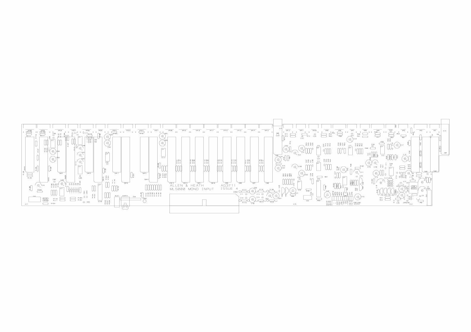
duncanda
D2
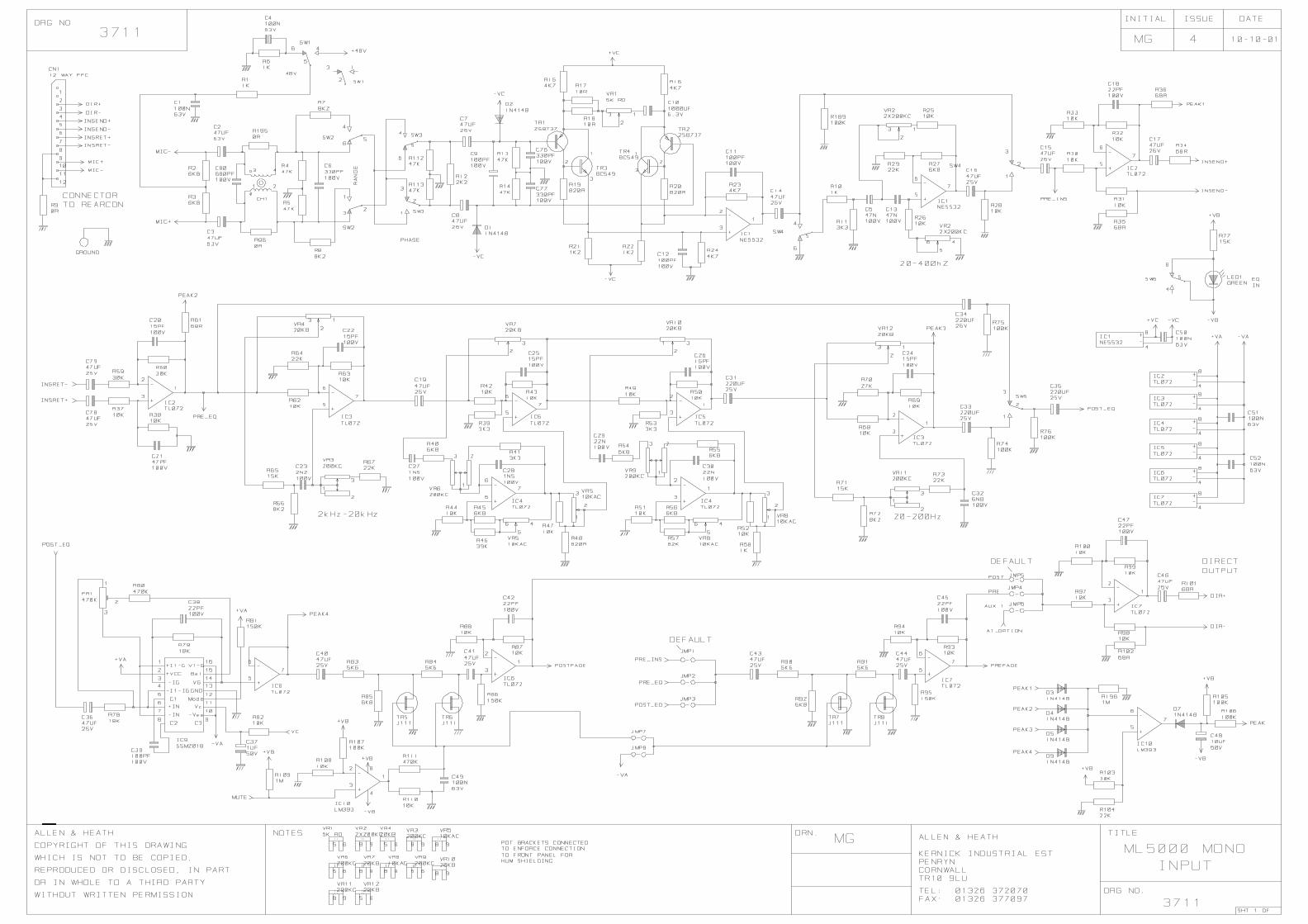
duncanda
D3

duncanda
D4

duncanda
D5
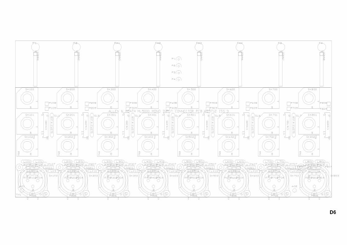
duncanda
D6

duncanda
duncanda
D7

duncanda
D8
duncanda

Kernick Industrial Estate,Penryn, Cornwall,England. TR10 9LU
+44 (0)8707 556250+44 (0)8707 556251 3
ML5000 4SM CONN PCB
C4845 2 5
PAGE:
TITLE:
DRG No: ISSUE: SHEET: OF
ISSUE BY DATE
FILE: C4845_3P2.Sch 10:38:56 3-Dec-2002
ALLEN&HEATHTel:Fax: PRINTED:
A B C D E F G H
a
b
c
d
e
T
R
CN1JACK V3M
T
R
CN2JACK V3M
3
12
0
CN3
XLR NC3FAV20
3
12
0
CN4
XLR NC3FAV20
L1DSS306
L2DSS306
L3DSS306
L4DSS306
P1PIN
P2PIN
P3PIN
P4PIN
P6PIN
P5PIN
P7PIN
P8PIN
P9PIN
P10PIN
P12PIN
P11PIN
12
34
56
78
910
1112
CN5
FLEX SKT 12 WAY VERT
P13PIN-SOLDER 1.2MM
P14PIN-SOLDER 1.2MM
STEREO 1
INPUT B
L
L
R
R
T
R
CN1_1JACK V3M
T
R
CN2_1JACK V3M
3
12
0
CN3_1
XLR NC3FAV20
3
12
0
CN4_1
XLR NC3FAV20
L1_1DSS306
L2_1DSS306
L3_1DSS306
L4_1DSS306
P1_1PIN
P2_1PIN
P3_1PIN
P4_1PIN
P6_1PIN
P5_1PIN
P7_1PIN
P8_1PIN
P9_1PIN
P10_1PIN
P12_1PIN
P11_1PIN
12
34
56
78
910
1112
CN5_1
FLEX SKT 12 WAY VERT
P13_1PIN-SOLDER 1.2MM
P14_1PIN-SOLDER 1.2MM
STEREO 2
INPUT B
L
L
R
R
AAT2 18-04-02
C1 NF C2 NF
AAT3 02-05-02
duncanda
duncanda
D9
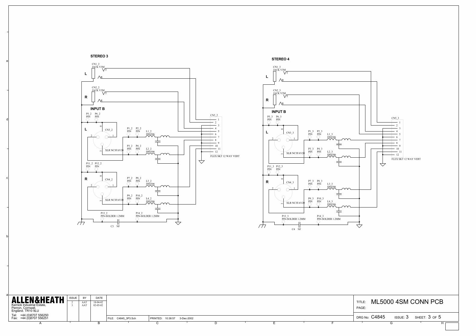
Kernick Industrial Estate,Penryn, Cornwall,England. TR10 9LU
+44 (0)8707 556250+44 (0)8707 556251 3
ML5000 4SM CONN PCB
C4845 3 5
PAGE:
TITLE:
DRG No: ISSUE: SHEET: OF
ISSUE BY DATE
FILE: C4845_3P3.Sch 10:38:57 3-Dec-2002
ALLEN&HEATHTel:Fax: PRINTED:
A B C D E F G H
a
b
c
d
e
T
R
CN1_2JACK V3M
T
R
CN2_2JACK V3M
3
12
0
CN3_2
XLR NC3FAV20
3
12
0
CN4_2
XLR NC3FAV20
L1_2DSS306
L2_2DSS306
L3_2DSS306
L4_2DSS306
P1_2PIN
P2_2PIN
P3_2PIN
P4_2PIN
P6_2PIN
P5_2PIN
P7_2PIN
P8_2PIN
P9_2PIN
P10_2PIN
P12_2PIN
P11_2PIN
12
34
56
78
910
1112
CN5_2
FLEX SKT 12 WAY VERT
P13_2PIN-SOLDER 1.2MM
P14_2PIN-SOLDER 1.2MM
STEREO 3
INPUT B
L
L
R
R
T
R
CN1_3JACK V3M
T
R
CN2_3JACK V3M
3
12
0
CN3_3
XLR NC3FAV20
3
12
0
CN4_3
XLR NC3FAV20
L1_3DSS306
L2_3DSS306
L3_3DSS306
L4_3DSS306
P1_3PIN
P2_3PIN
P3_3PIN
P4_3PIN
P6_3PIN
P5_3PIN
P7_3PIN
P8_3PIN
P9_3PIN
P10_3PIN
P12_3PIN
P11_3PIN
12
34
56
78
910
1112
CN5_3
FLEX SKT 12 WAY VERT
P13_3PIN-SOLDER 1.2MM
P14_3PIN-SOLDER 1.2MM
STEREO 4
INPUT B
L
L
R
R
AAT2 18-04-02
C3 NFC4 NF
AAT3 02-05-02
duncanda
D10
duncanda

Kernick Industrial Estate,Penryn, Cornwall,England. TR10 9LU
+44 (0)8707 556250+44 (0)8707 556251 3
ML5000 4SM CONN PCB
C4845 4 5
PAGE:
TITLE:
DRG No: ISSUE: SHEET: OF
ISSUE BY DATE
FILE: C4845_3P4.Sch 10:38:57 3-Dec-2002
ALLEN&HEATHTel:Fax: PRINTED:
A B C D E F G H
a
b
c
d
e
T
R
CN6JACK V3M
T
R
CN7JACK V3M
T
R
CN8JACK V5M
3
12
0
CN9
XLR NC3FAV20
L5DSS306
L6DSS306
P15PIN
P16PIN
P17PIN
P18PIN
P20PIN
P19PIN
12
34
56
78
910
1112
CN10
FLEX SKT 12 WAY VERT
P23PIN-SOLDER 1.2MM
P24PIN-SOLDER 1.2MM
MONO 1
INSERT SEND
DIRECT OUT
R
INSERT RETURN
MIC IN
P22PIN
P21PIN
T
R
CN6_1JACK V3M
T
R
CN7_1JACK V3M
T
R
CN8_1JACK V5M
3
12
0
CN9_1
XLR NC3FAV20
L5_1DSS306
L6_1DSS306
P15_1PIN
P16_1PIN
P17_1PIN
P18_1PIN
P20_1PIN
P19_1PIN
12
34
56
78
910
1112
CN10_1
FLEX SKT 12 WAY VERT
P23_1PIN-SOLDER 1.2MM
P24_1PIN-SOLDER 1.2MM
MONO 2
INSERT SEND
DIRECT OUT
R
INSERT RETURN
MIC IN
P22_1PIN
P21_1PIN
AAT2 18-04-02
C5 100N 100V/MLCC6 100N 100V/MLC
AAT3 02-05-02
duncanda
duncanda
D11
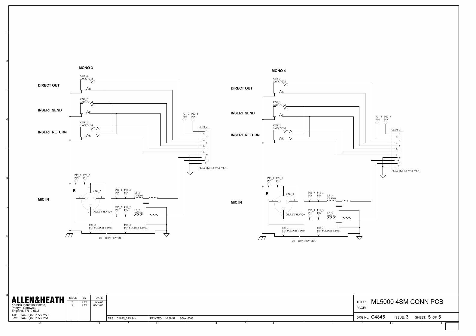
Kernick Industrial Estate,Penryn, Cornwall,England. TR10 9LU
+44 (0)8707 556250+44 (0)8707 556251 3
ML5000 4SM CONN PCB
C4845 5 5
PAGE:
TITLE:
DRG No: ISSUE: SHEET: OF
ISSUE BY DATE
FILE: C4845_3P5.Sch 10:38:57 3-Dec-2002
ALLEN&HEATHTel:Fax: PRINTED:
A B C D E F G H
a
b
c
d
e
T
R
CN6_2JACK V3M
T
R
CN7_2JACK V3M
T
R
CN8_2JACK V5M
3
12
0
CN9_2
XLR NC3FAV20
L5_2DSS306
L6_2DSS306
P15_2PIN
P16_2PIN
P17_2PIN
P18_2PIN
P20_2PIN
P19_2PIN
12
34
56
78
910
1112
CN10_2
FLEX SKT 12 WAY VERT
P23_2PIN-SOLDER 1.2MM
P24_2PIN-SOLDER 1.2MM
MONO 3
INSERT SEND
DIRECT OUT
R
INSERT RETURN
MIC IN
P22_2PIN
P21_2PIN
T
R
CN6_3JACK V3M
T
R
CN7_3JACK V3M
T
R
CN8_3JACK V5M
3
12
0
CN9_3
XLR NC3FAV20
L5_3DSS306
L6_3DSS306
P15_3PIN
P16_3PIN
P17_3PIN
P18_3PIN
P20_3PIN
P19_3PIN
12
34
56
78
910
1112
CN10_3
FLEX SKT 12 WAY VERT
P23_3PIN-SOLDER 1.2MM
P24_3PIN-SOLDER 1.2MM
MONO 4
INSERT SEND
DIRECT OUT
R
INSERT RETURN
MIC IN
P22_3PIN
P21_3PIN
AAT2 18-04-02
C7 100N 100V/MLCC8 100N 100V/MLC
AAT3 02-05-02
duncanda
D12
duncanda

duncanda
D13

duncanda
D14

duncanda
D15

duncanda
D16

duncanda
D17

duncanda
D18

duncanda
D19

duncanda
D20

duncanda
D21
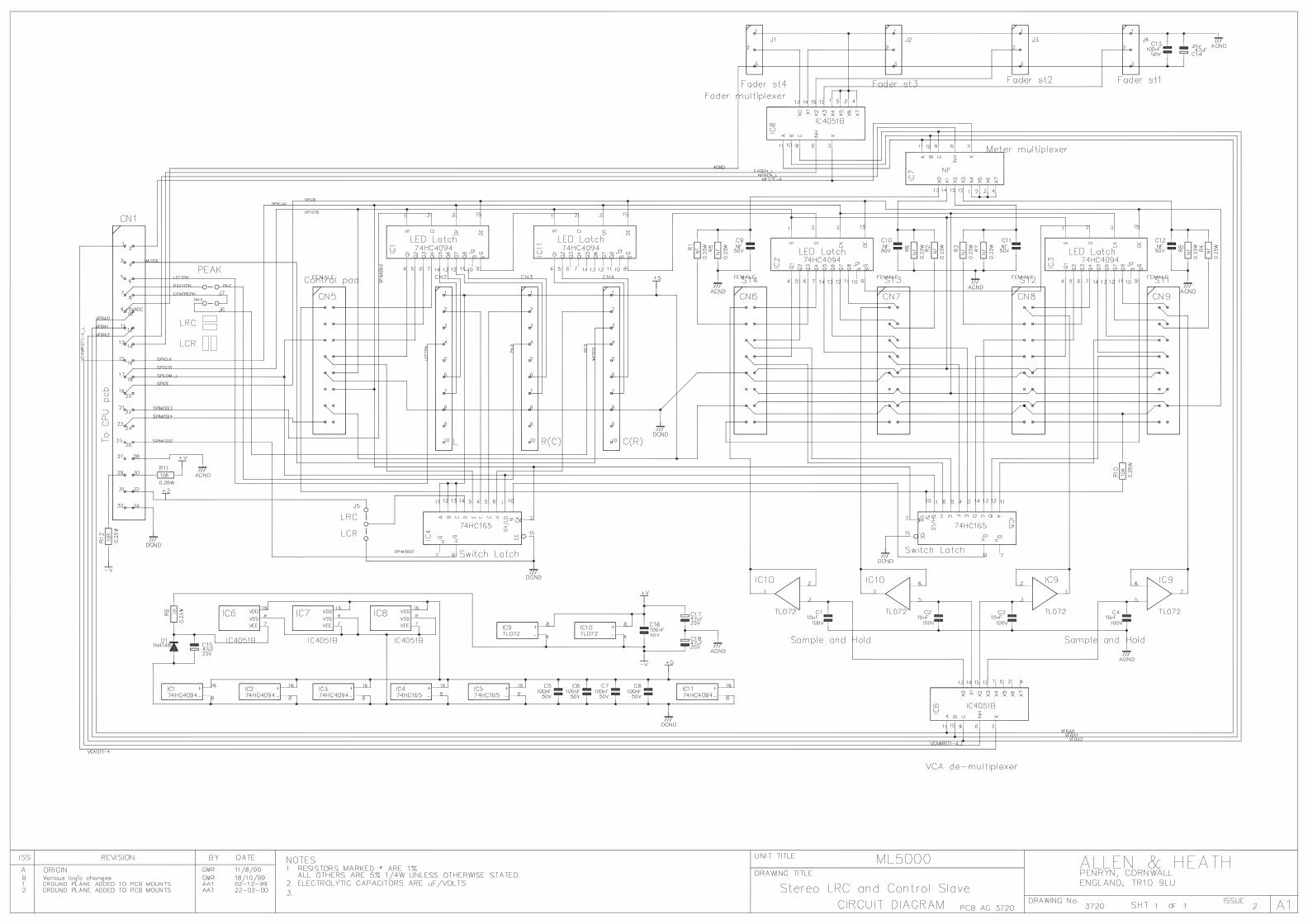
duncanda
D22
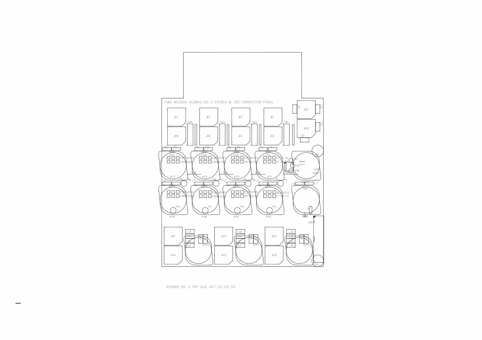
duncanda
D23

duncanda
D24
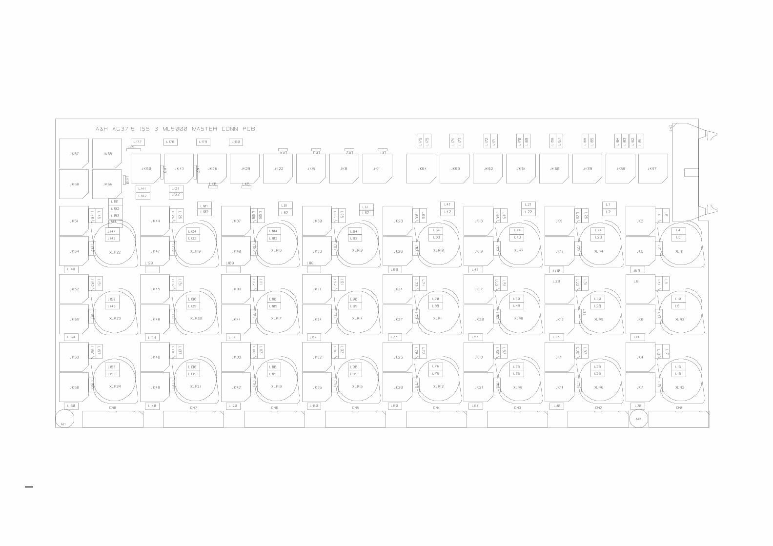
duncanda
D25
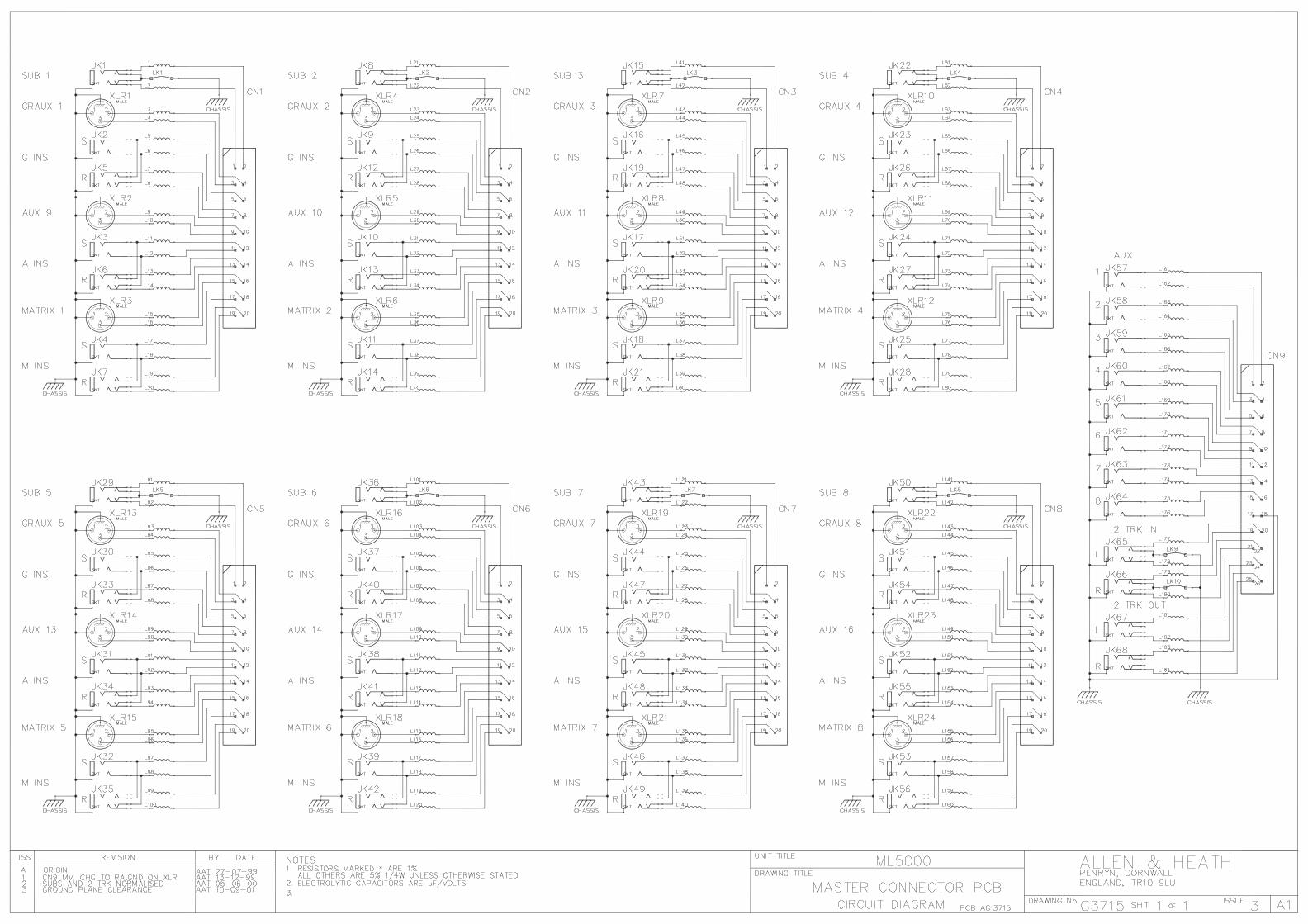
duncanda
D26

duncanda
D27
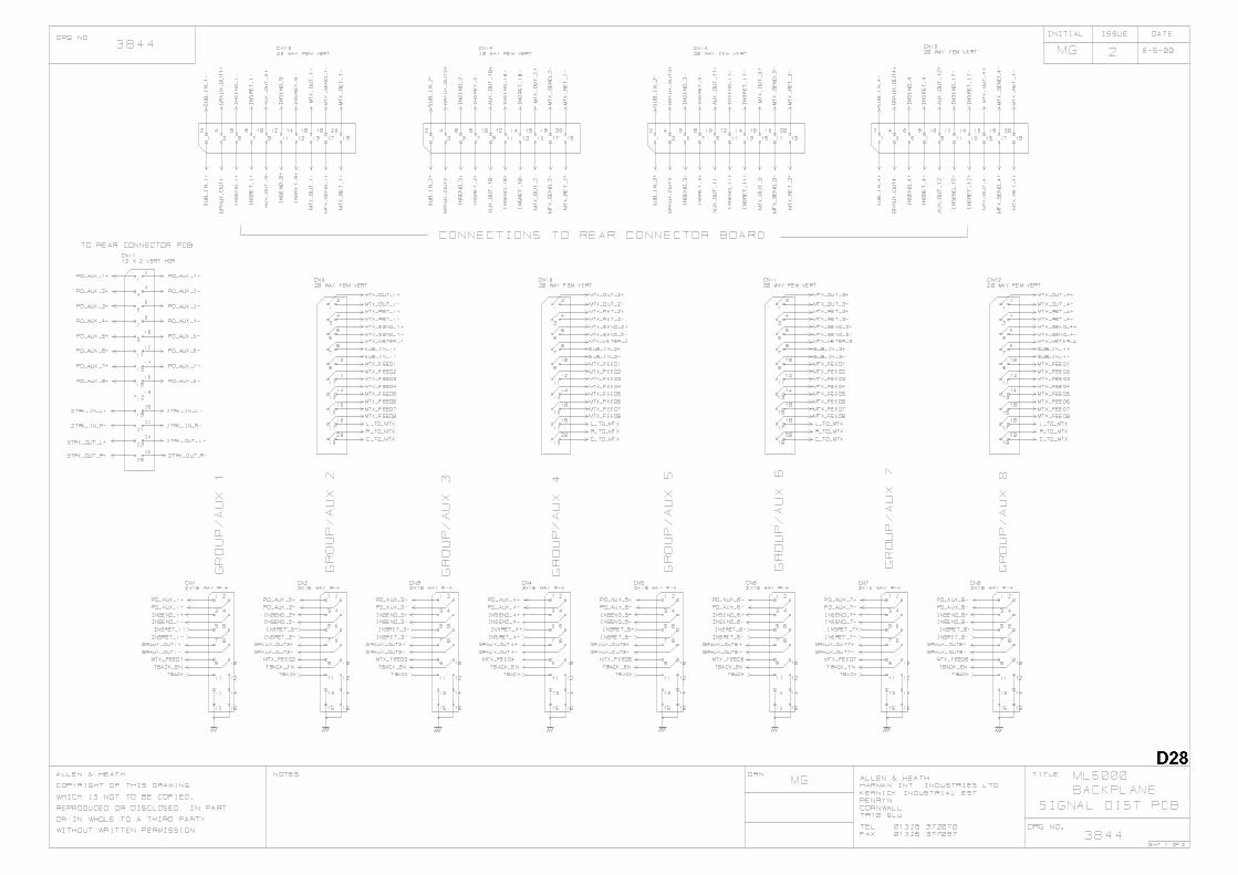
duncanda
duncanda
D28

duncanda
duncanda
D29
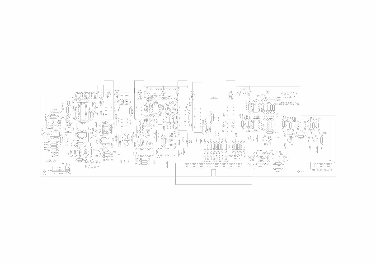
duncanda
D30

duncanda
duncanda
D31

duncanda
D32
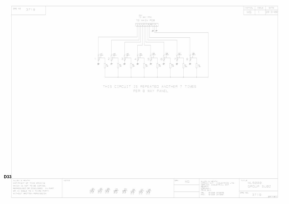
duncanda
duncanda
D33
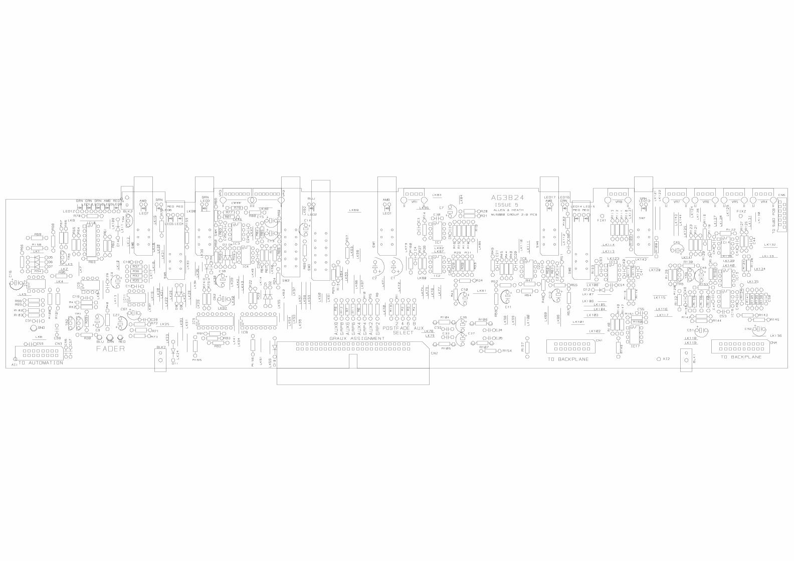
duncanda
D34

duncanda
duncanda
D35

duncanda
duncanda
D36

duncanda
D37

duncanda
duncanda
D38

duncanda
duncanda
D39

duncanda
duncanda
D40
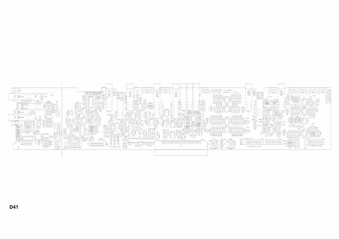
duncanda
D41

duncanda
duncanda
D42

duncanda
duncanda
D43
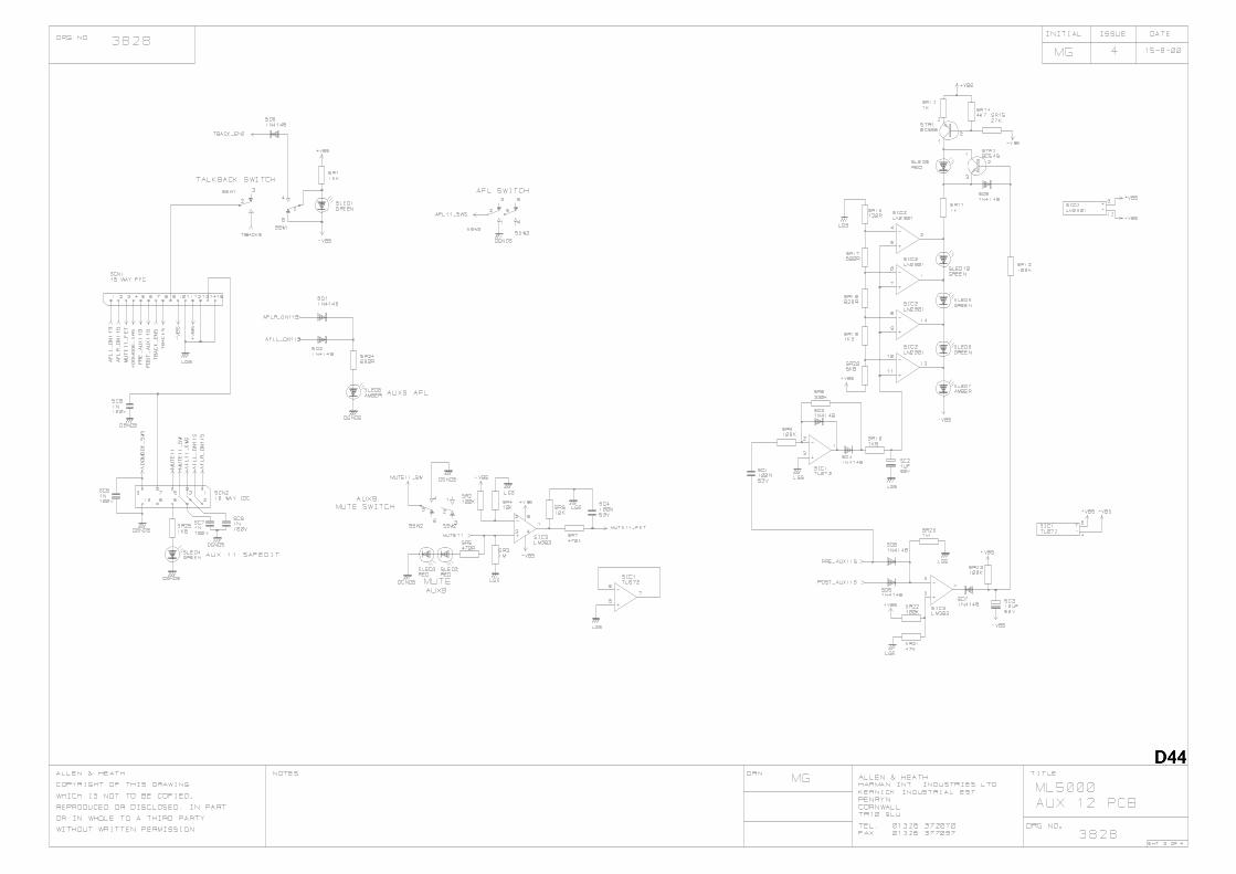
duncanda
duncanda
D44

duncanda
duncanda
D45

duncanda
D46

duncanda
duncanda
D47

duncanda
duncanda
D48

duncanda
duncanda
D49
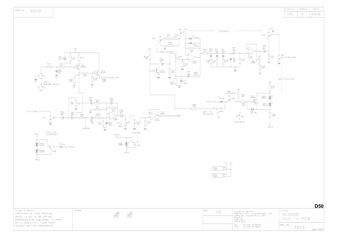
duncanda
duncanda
D50

duncanda
D51

duncanda
duncanda
D52

duncanda
duncanda
D53

duncanda
duncanda
D54

duncanda
D55

duncanda
duncanda
D56

duncanda
duncanda
D57
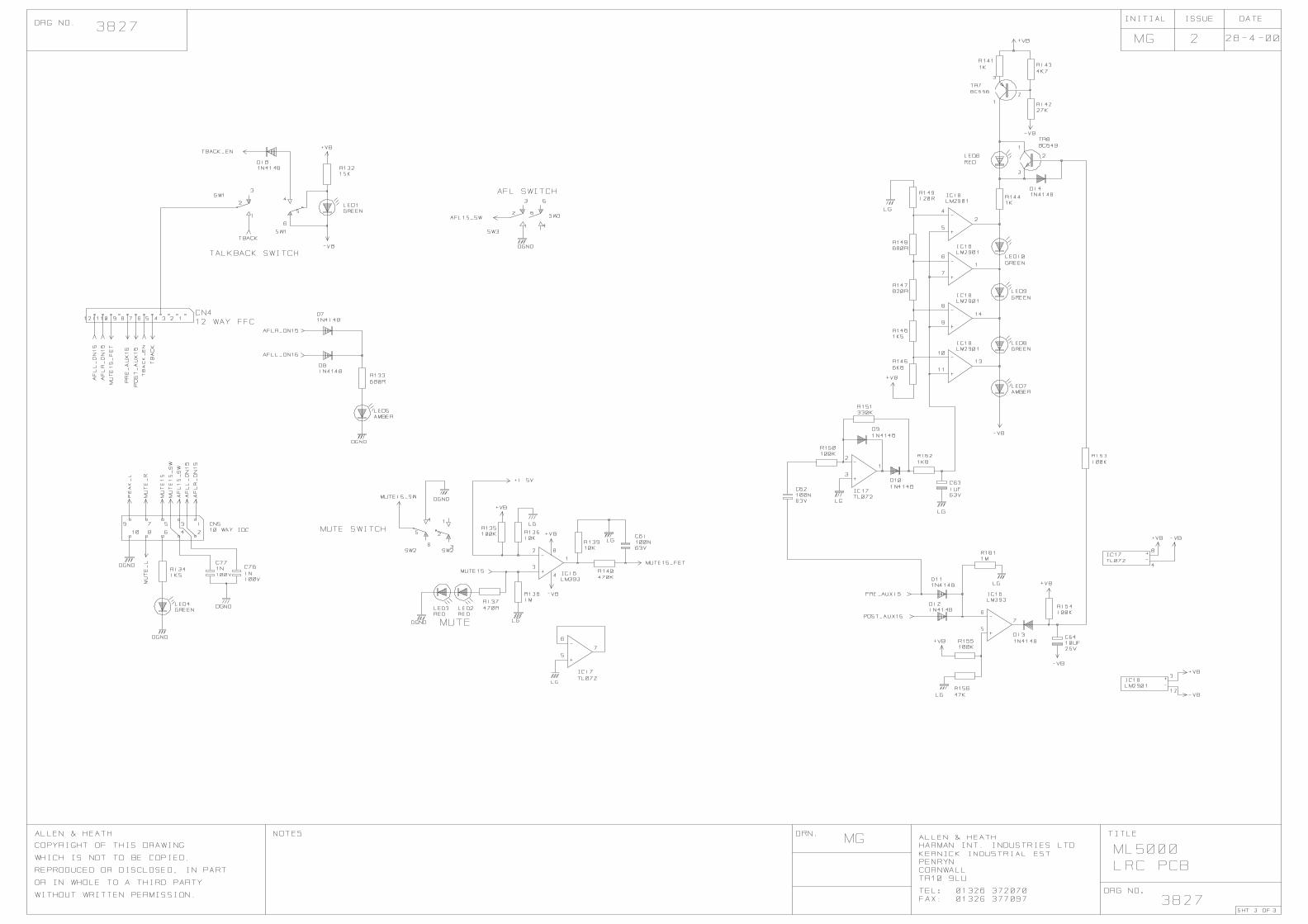
duncanda
duncanda
D58
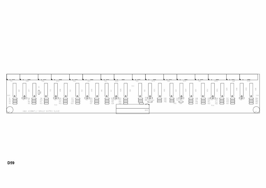
duncanda
D59

duncanda
D60

duncanda
D61

duncanda
D62

duncanda
D63

duncanda
D64

duncanda
duncanda
D65
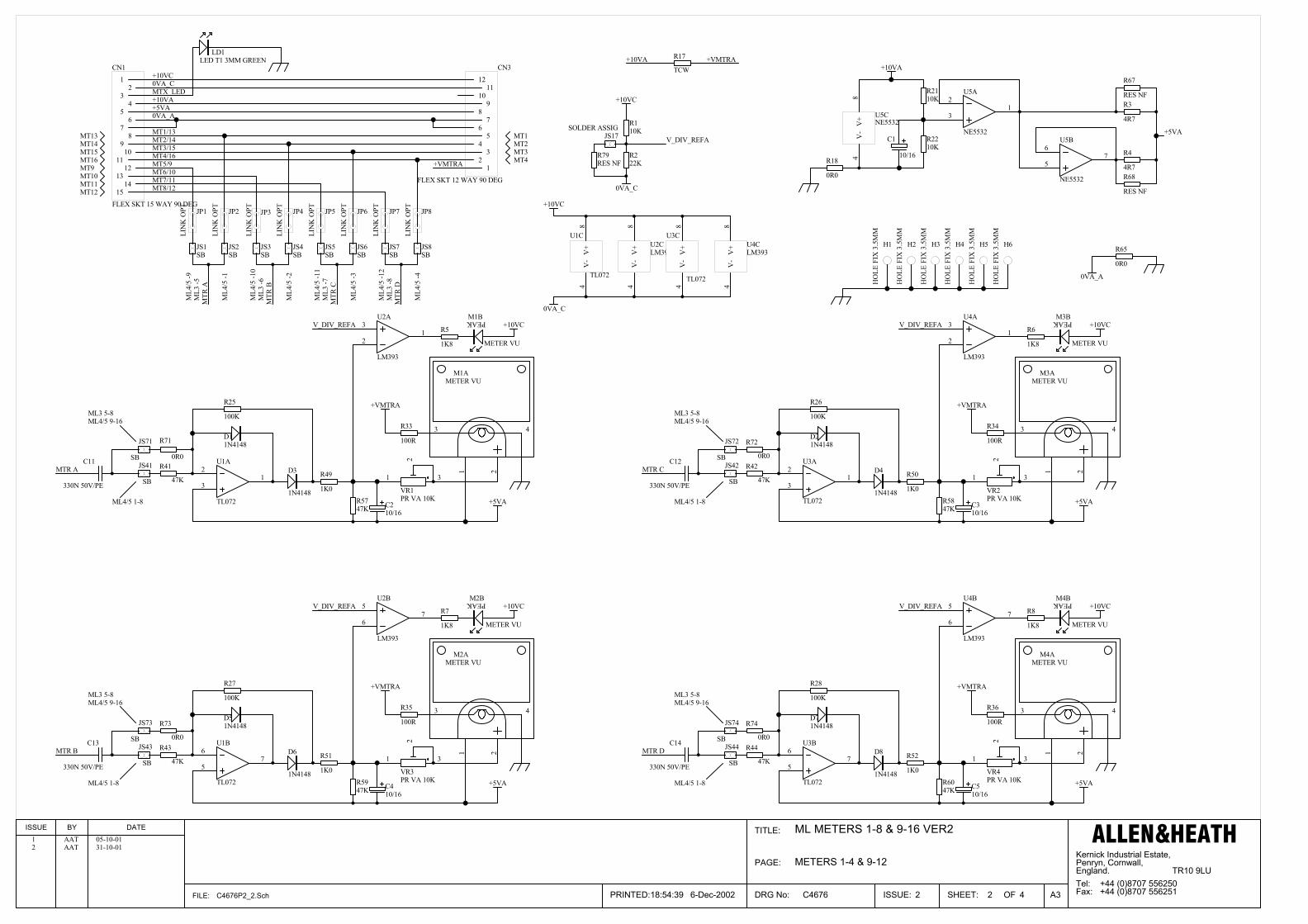
Kernick Industrial Estate,Penryn, Cornwall,England. TR10 9LU
+44 (0)8707 556250+44 (0)8707 5562512
ML METERS 1-8 & 9-16 VER2
C4676 2 4
PAGE:
TITLE:
DRG No: ISSUE: SHEET: OF
ISSUE BY DATE
FILE: C4676P2_2.Sch 18:54:39 6-Dec-2002 A3
ALLEN&HEATH
Tel:Fax:PRINTED:
1 2
3 4
M1AMETER VU
PEAKM1B
METER VU
R33
100R
R5747K
R25
100K
D11N4148
D3
1N4148
C210/16
R49
1K0
+5VA
C11
330N 50V/PE
+VMTRA
MTR A1 2
3 4
M2AMETER VU
PEAKM2B
METER VU
R35
100R
R5947K
R27
100K
D51N4148
D6
1N4148
C410/16
R51
1K0
+5VA
C13
330N 50V/PE
+VMTRA
MTR B
1 2
3 4
M3AMETER VU
PEAKM3B
METER VU
R34
100R
R5847K
R26
100K
D21N4148
D4
1N4148
C310/16
R50
1K0
+5VA
C12
330N 50V/PE
+VMTRA
MTR C
1 2
3 4
M4AMETER VU
PEAKM4B
METER VU
R36
100R
R6047K
R28
100K
D71N4148
D8
1N4148
C510/16
R52
1K0
+5VA
C14
330N 50V/PE
+VMTRA
MTR D
JP2LI
NK
OPT JP8
LIN
K O
PTJP1
LIN
K O
PT JP7
LIN
K O
PTJP6
LIN
K O
PTJP5
LIN
K O
PTJP4
LIN
K O
PTJP3
LIN
K O
PT
MTR
A
MTR
B
MTR
C
MTR
D
MT1MT2MT3MT4
MT12MT11MT10MT9MT16MT15MT14MT13
+10VC0VA_C
+10VA+5VA0VA_A
MT1/13MT2/14MT3/15MT4/16MT5/9MT6/10MT7/11MT8/12
MTX_LED
LD1LED T1 3MM GREEN
+VMTRA
+10VA +VMTRAR17
TCW
V_DIV_REFA
V_DIV_REFA
V_DIV_REFA
V_DIV_REFA
R110K
R222K
V_DIV_REFA
+10VC
0VA_C
R5
1K8
R6
1K8
R8
1K8
R7
1K8
+10VC
+10VC +10VC
+10VC
ML3
-5
ML3
-6
ML3
-7
ML3
-8
0VA_C
+10VC
R4
4R7
R3
4R7
R2110K
R2210K
R18
0R0
C1
10/16
+10VA
+5VA
1 AAT 05-10-01
H1
HO
LE F
IX 3
.5M
M
H2
HO
LE F
IX 3
.5M
M
H3
HO
LE F
IX 3
.5M
M
H4
HO
LE F
IX 3
.5M
M
H5
HO
LE F
IX 3
.5M
M
H6
HO
LE F
IX 3
.5M
M
R65
0R0
0VA_A
METERS 1-4 & 9-12
R71
0R0
R73
0R0
R72
0R0
R74
0R0
R42
47K
R44
47K
R43
47K
R41
47K
JS71
SBJS41
SB
JS73
SBJS43
SB
JS44
SB
JS74
SB
JS42
SB
JS72
SB
JS1SB
JS2SB
JS3SB
JS4SB
JS5SB
JS6SB
JS7SB
JS8SB
ML4
/5 -9
ML4
/5 -1
ML4
/5 -1
0
ML4
/5 -2
ML4
/5 -1
1
ML4
/5 -3
ML4
/5 -1
2
ML4
/5 -4
ML3 5-8 ML3 5-8
ML3 5-8 ML3 5-8
ML4/5 9-16 ML4/5 9-16
ML4/5 9-16 ML4/5 9-16
ML4/5 1-8 ML4/5 1-8
ML4/5 1-8 ML4/5 1-8
1 3
2
VR1PR VA 10K
1 3
2
VR2PR VA 10K
1 3
2
VR3PR VA 10K
1 3
2
VR4PR VA 10K
3
21
U2A
LM393
3
21
U4A
LM393
5
67
U4B
LM393
5
67
U2B
LM393V
-4
V+
8
U2CLM393
V-
4V
+8
U4CLM393
3
21
U1A
TL072
5
67
U1B
TL072
V-
4V
+8
U1C
TL072
3
21
U3A
TL072
5
67
U3B
TL072
V-
4V
+8
U3C
TL072
3
21
U5A
NE5532
5
67
U5B
NE5532
V-
4V
+8
U5CNE5532
12
34
56
78
910
1112
1314
15
CN1
FLEX SKT 15 WAY 90 DEG
12
34
56
78
910
1112
CN3
FLEX SKT 12 WAY 90 DEG
2 AAT 31-10-01
R67
RES NF
R68
RES NF
R79RES NF
JS17SOLDER ASSIG
duncanda
D66

Kernick Industrial Estate,Penryn, Cornwall,England. TR10 9LU
+44 (0)8707 556250+44 (0)8707 5562512
ML METERS 1-8 & 9-16 VER2
C4676 3 4
PAGE:
TITLE:
DRG No: ISSUE: SHEET: OF
ISSUE BY DATE
FILE: C4676P3_2.Sch 18:58:37 6-Dec-2002 A3
ALLEN&HEATH
Tel:Fax:PRINTED:
JP10LI
NK
OPT JP16
LIN
K O
PTJP9
LIN
K O
PT JP15
LIN
K O
PTJP14
LIN
K O
PTJP13
LIN
K O
PTJP12
LIN
K O
PTJP11
LIN
K O
PT
MT1MT2MT3MT4
MT8MT7MT6MT5
MT16MT15MT14MT13
+10VD0VA_D
+10VB+5VB0VA_B
MT1/13BMT2/14BMT3/15BMT4/16BMT5/9BMT6/10BMT7/11BMT8/12B
MTR
E
MTR
F
MTR
G
MTR
H
+VMTRB
+10VB +VMTRBR19
TCW
1 2
3 4
M5AMETER VU
PEAKM5B
METER VU
R37
100R
R6147K
R29
100K
D91N4148
D10
1N4148
C710/16
R53
1K0
+5VB
C15
330N 50V/PE
+VMTRB
MTR E1 2
3 4
M6AMETER VU
PEAKM6B
METER VU
R39
100R
R6347K
R31
100K
D131N4148
D14
1N4148
C910/16
R55
1K0
+5VB
C17
330N 50V/PE
+VMTRB
MTR F
1 2
3 4
M7AMETER VU
PEAKM7B
METER VU
R38
100R
R6247K
R30
100K
D111N4148
D12
1N4148
C810/16
R54
1K0
+5VB
C16
330N 50V/PE
+VMTRB
MTR G
1 2
3 4
M8AMETER VU
PEAKM8B
METER VU
R40
100R
R6447K
R32
100K
D151N4148
D16
1N4148
C1010/16
R56
1K0
+5VB
C18
330N 50V/PE
+VMTRB
MTR H
V_DIV_REFB
V_DIV_REFB
V_DIV_REFB
V_DIV_REFB
R910K
R1022K
V_DIV_REFB
+10VD
0VA_D
R13
1K8
R14
1K8
R16
1K8
R15
1K8
+10VD
+10VD +10VD
+10VD
+10VD
0VA_DML3
-1
ML3
-2
ML3
-3
ML3
-4
R12
4R7
R11
4R7
R2310K
R2410K
R20
0R0
C6
10/16
+10VB
+5VB
1 AAT 05-10-01
H7
HO
LE F
IX 3
.5M
M
H8
HO
LE F
IX 3
.5M
M
H9
HO
LE F
IX 3
.5M
M
H10
HO
LE F
IX 3
.5M
M
H11
HO
LE F
IX 3
.5M
M
R66
0R0
0VA_B
METERS 5-8 & 13-16
R45
47K
R47
47K
R46
47K
R48
47K
R75
0R0
R77
0R0
R76
0R0
R78
0R0
JS75
SBJS45
SB
JS47
SB
JS77
SBJS48
SB
JS78
SB
JS46
SB
JS76
SB
JS9SB
JS10SB
JS11SB
JS12SB
JS13SB
JS14SB
JS15SB
JS16SB
ML4
/5 -1
3
ML4
/5 -5
ML4
/5 -1
4
ML4
/5 -6
ML4
/5 -1
5
ML4
/5 -7
ML4
/5 -1
6
ML4
/5 -8
ML3 1-4 ML3 1-4
ML3 1-4 ML3 1-4
ML4/5 1-8 ML4/5 1-8
ML4/5 1-8 ML4/5 1-8
ML4/5 9-16 ML4/5 9-16
ML4/5 9-16 ML4/5 9-16
1 3
2
VR5PR VA 10K
1 3
2
VR6PR VA 10K
1 3
2
VR7PR VA 10K
1 3
2
VR8PR VA 10K
3
21
U6A
TL072
5
67
U6B
TL072
V-
4V
+8
U6CTL072
3
21
U8A
TL072
5
67
U8B
TL072
V-
4V
+8
U8CTL072
3
21
U7A
LM393
5
67
U7B
LM393V
-4
V+
8
U7CLM393
3
21
U9A
LM393
5
67
U9B
LM393
V-
4V
+8
U9CLM393
3
21
U10A
NE5532
5
67
U10B
NE5532
V-
4V
+8
U10CNE5532
12
34
56
78
910
1112
CN4
FLEX SKT 12 WAY 90 DEG
12
34
56
78
910
1112
1314
15
CN2
FLEX SKT 15 WAY 90 DEG
2 AAT 30-10-01
ML3MT4ML3MT3ML3MT2ML3MT1
R69
RES NF
R70
RES NF
JS18SOLDER ASSIG
R80RES NF
duncanda
D67

duncanda
D68

Kernick Industrial Estate,Penryn, Cornwall,England. TR10 9LU
+44 (0)8707 556250+44 (0)8707 5562511
ML MASTER METER PCB
4357 1 2
PAGE:
TITLE:
DRG No: ISSUE: SHEET: OF
ISSUE BY DATE
FILE: C4357P2_1.Sch 19:02:59 6-Dec-2002 A3
ALLEN&HEATH
Tel:Fax:PRINTED:
C1
330N
R147K
RS1A47K
RS1B47K
RS1C47K
RS1D47K
3
21
U1A
NE5532
D1
IN4148
D2
IN4148
R7 100K
R12
1K
R247K
1 3
2
VR110K
1 2
3 4
M1AMETER VU
PEAK
M1BMETER VU
A14
11
13
12
U9ACD4053BCM_1
2
1
10
15B
U9BCD4053BCM_1
5
3
9
4C
U9CCD4053BCM_1
INH 6
VEE
7
VSS8 VD
D16U9D
CD4053BCM_1
R15
100R
C410/16
MTRL
+12
+5
3
21
U4A
LM393
5
67
U4B
LM393
V-
4V
+8
U4C
LM393
R10
10KR11
10K
+12
R34
6K8
+17
C2
330N
R347K
3
21
U2A
NE5532
D3
IN4148
D4
IN4148
R8 100K
R13
1K
R447K
1 3
2
VR210K
1 2
3 4
M2AMETER VU
PEAK
M2BMETER VU
R16
100R
C510/16
MTRR
+12
+5 +12
R35
6K8
C3
330N
R547K
3
21
U3A
NE5532
D5
IN4148
D6
IN4148
R9 100K
R14
1K
R647K
1 3
2
VR310K
1 2
3 4
M3AMETER VU
PEAK
M3BMETER VU
R17
100R
C610/16
MTRC
+12
+5
3
21
U5A
LM393
+12
R36
6K8
+VPEAK
+VPEAK
+VPEAK
2
1
10
15B
U10BCD4053BCM_1
A14
11
13
12
U10ACD4053BCM_1
5
3
9
4C
U10CCD4053BCM_1
R1910K
R1810K
R2010KR2110K
R2210KR2310K
R2410K
R2510K
R2910K
R2810K
R3010KR3118K
R3218K
L_SIG_IN
AFLL_SIG
AFLL_SIG
R_SIG_IN
PAFL_SIG
PAFL_SIG
C_SIG_IN
5
67
U1BTL072
V-
4V
+8
U1C
TL072
5
67
U2BTL072
V-
4V
+8
U2C
TL072
5
67
U3BTL072
V-
4V
+8
U3C
TL072
R26
10K
R27
10K
R33
10K
MTRL
MTRR
MTRC
V-
4V
+8
U5C
LM393
INH 6
VEE
7
VSS8 VD
D16U10D
CD4053BCM_1
AFL_DC
PFL_DC
ACTIVE_M
2
1
10
15B
U6BCD4053BCM_1
5
3
9
4C
U6CCD4053BCM_1
A14
11
13
12
U6ACD4053BCM_1
2
1
10
15B
U8BCD4053BCM_1
RS2A47K
RS2B47K
RS2C47KRS2D47K
RS3A47K
RS3B47K
RS3C47K
RS3D47K
RS4A47K
RS4B47K
RS4C47K
RS4D47K
RS5A47K
RS5B47K
RS5C47KRS5D
47K
2
1
10
15B
U7BCD4053BCM_1
5
3
9
4C
U7CCD4053BCM_1
A14
11
13
12
U7ACD4053BCM_1
5
3
9
4C
U8CCD4053BCM_1
RS6A47K
RS6B47K
RS6C47K
RS6D47K
RS7A47K
RS7B47K
RS7C47KRS7D47K
RS8A47K
RS8B47K
RS8C47KRS8D47K
A14
11
13
12
U8A
CD4053BCM_1
MT9
MT10
MT11
MT12
MT13
MT14
MT15
MT16
AUX9
AUX10
AUX11
AUX12
AUX13
AUX14
AUX15
AUX16
MTX1
MTX2
MTX3
MTX4
MTX5
MTX6
MTX7
MTX8
METERS=MTX
+17
-17
+5
-5
INH 6
VEE
7
VSS8 VD
D16U6D
CD4053BCM_1
INH 6
VEE
7
VSS8 VD
D16U7D
CD4053BCM_1
+5
-5
INH 6
VEE
7
VSS8 VD
D16U8D
CD4053BCM_1
+5
-5
5
67
U5B
LM393
R4910K
R5010K
PAFL_SIG
-17
A JB 12/01/01 1 JB 06/02/01
ORIGINSIL RESISTOR BLOCK MOVED, PADS ADDED, VALUE CHANGES.
duncanda
D69

Kernick Industrial Estate,Penryn, Cornwall,England. TR10 9LU
+44 (0)8707 556250+44 (0)8707 5562511
ML MASTER METER PCB
4357 2 2
PAGE:
TITLE:
DRG No: ISSUE: SHEET: OF
ISSUE BY DATE
FILE: C4357P3_1.Sch 19:03:51 6-Dec-2002 A3
ALLEN&HEATH
Tel:Fax:PRINTED:
20 20
11
1919
2 2
18 18
33
1717
4 4
16 16
55
1515
6 6
14 14
77
1313
8 8
12 1299
1111 10 10
CN3
CONN 10X2
20 20
11
1919
2 2
18 18
33
1717
4 4
16 16
55
1515
6 6
14 14
77
1313
8 8
12 1299
1111 10 10
CN4
CONN 10X2
12
34
56
78
910
1112
CN5
FLEX SKT 12 WAY
12
34
56
78
910
1112
1314
15
CN1
FLEX SKT 15 WAY (VERT)
3
21
U11ATL072
5
67
U11BTL072
V-
4V
+8
U11CTL072
R3720K 1%
R388K2 1%
R398K2 1%
R4220K 1%
+17
C733/10
-17
C833/10
+5
-5
+17
-17
R430R
+12
+12
12
34
56
78
910
1112
1314
15
CN2
FLEX SKT 15 WAY
+12
+12
AUX1AUX2AUX3AUX4AUX5AUX6AUX7AUX8
MT9MT10MT11MT12
MT13MT14MT15MT16
R454K7
AFL_DC
MTX1 MTX2MTX3 MTX4MTX5 MTX6MTX7 MTX8METER_MOPAFL_SIG
CALL_LED
-17
+12 +12
+17 R46100K
R474K7
PFL_DCACTIVE_I
AUX1 AUX2AUX3 AUX4AUX5 AUX6AUX7 AUX8AUX9 AUX10AUX11 AUX12AUX13 AUX14AUX15 AUX16L_SIG_INC_SIG_IN
R_SIG_IN
D8IN4148
D7IN4148
R48100K
PFL_DC
ACTIVE_M
+17-17
+5
PAFL_LEDAFL_LEDBIG_YELLMTRLMTRRMTRC
1
23
U12A74LS00
4
56
U12B
74LS00
89
10
U12C
74LS00
1112
13
U12D
74LS00
ACTIVE_I PAFL_LED
AFL_DCAFL_LED
METERS=MTX
METER_MO
R40100K
+5
R41
1K5MTX_LED
METERS=MTX
R44
0RCALL_LED BIG_YELL
VCC +5
MTX_LED
AFLL_SIG
A JB 12/01/01 1 JB 06/02/01
ORIGINSIL RESISTOR BLOCK MOVED, PADS ADDED, VALUE CHANGES.
duncanda
D70

duncanda
D71
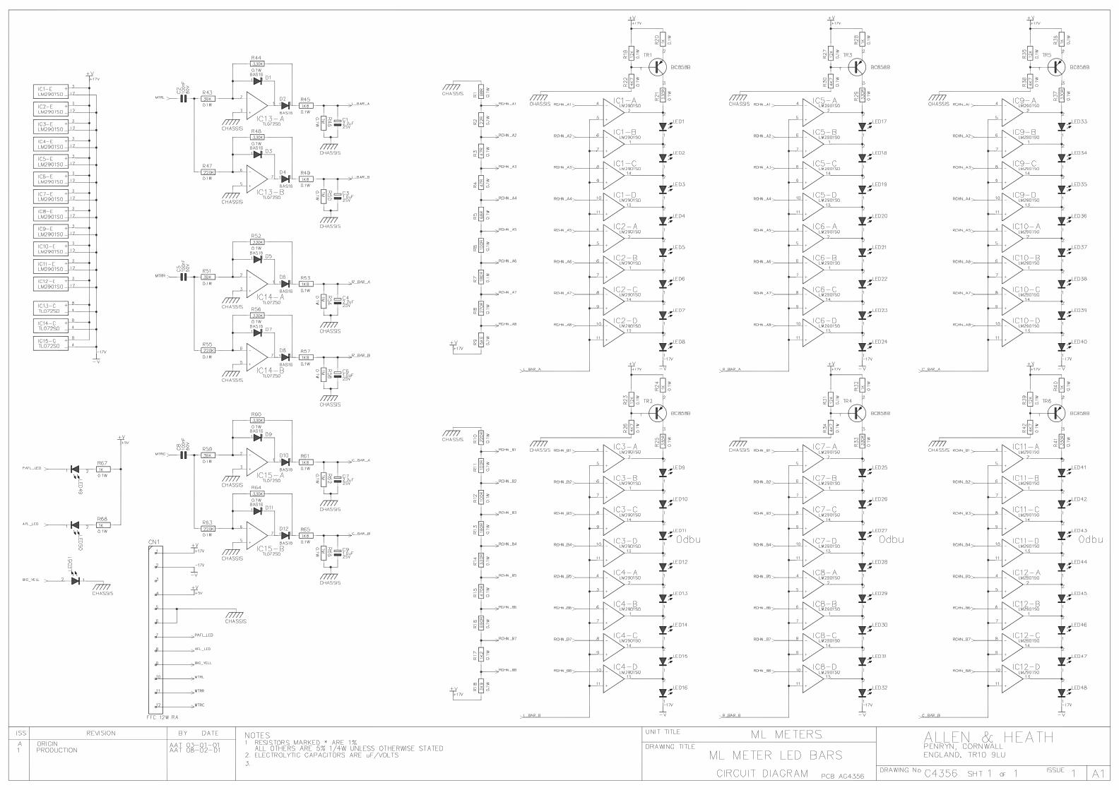
duncanda
D72

duncanda
duncanda
D73

Kernick Industrial Estate,Penryn, Cornwall,England. TR10 9LU
+44 (0)8707 556250+44 (0)8707 5562513
ML5000 MIDI POWER PCB
C3884 1 1
PAGE:
TITLE:
DRG No: ISSUE: SHEET: OF
ISSUE BY DATE
FILE: C3884_3.Sch 17:11:07 6-Dec-2002 A3
ALLEN&HEATH
Tel:Fax:PRINTED:
162738495
CN1
DB
9FH
(DM
RM
)
162738495
CN2
DB
9FH
(DM
RM
)SI
DEC
AR
1SI
DEC
AR
2
JP11LI
NK
OPT
R11K0
+5VL
SCAR1
S&M
R2120R
R3120R
SS
JP1
LINK OPTJP2
LINK OPTJP3
LINK OPTJP4
LINK OPT
JP5
LINK OPTJP6
LINK OPTJP7
LINK OPTJP8
LINK OPT
S
S
S
S
M
M
M
M
L2DSS306
L3DSS306
L4DSS306
L1DSS306
VC
C8
DE 3
B7
A6 D 4
RE 2
R 1
GN
D5
U1
SN75176BP
+5VL
C1100N 100V/MLC
R20
47R
C2100N 100V/MLC
+5VL
162738495
CN3
DB
9FH
(DM
RM
)R
S232
L5DSS306
L6DSS306
T1IN 11
T2IN 10
R1OUT 12
R2OUT 9
T1OUT14
T2OUT7
R1IN13
R2IN8
VC
C16
C1+1
C1-3
C2+4
C2-5
GN
D15
V+ 2
V- 6
U3
HIN202CP
C8100N 100V/MLC
C9100N 100V/MLC
+5VL
C10
100N 100V/MLC
C11
100N 100V/MLC
C12
100N 100V/MLC
R410K
R510K
14
25
3
0
CN4 DIN SKT FEMALE HA 5 PIN 180 DEG
14
25
3
0
CN5 DIN SKT FEMALE HA 5 PIN 180 DEG
14
25
3
0
CN6 DIN SKT FEMALE HA 5 PIN 180 DEG
C31N/MYL
C41N/MYL
C51N/MYL
C61N/MYL
C71N/MYL
C131N/MYL
L7
4.7UHL8
4.7UH
L9
4.7UHL10
4.7UH
L11
4.7UHL12
4.7UH
R6
220RR7
220R
R8
220R
R9
220RR10
220R
R15560R
R22
680R
R14560R
R21
680R
D11N4148
Q2
BC549
Q1
BC549
+5VL
+5VL
2
3
5
6
78
U6
6N136
+5VL
C28100N 100V/MLC
R168K2
8
910
U4C74HCT02
GN
D7
VC
C14
U5E
74H
CT0
2
GN
D7
VC
C14
U4E
74H
CT0
2
45
6
U4B
74HCT02
R11
47R
EXPTXEN
EXPTX
EXPRX
MIDITX
MIDIRX
MIDIRXMIDITX
MIDI_H
MIDI_H
EXPTXEXPTXENEXPRX
JP10
NF
JP9
LINK OPT
11
1213
U4D
74HCT02
R131K0
+5VL+5VL
R1210K
21
3
SW1SWITCH SLIDE (AL3081)
RS232
MIDI
C26
100N
100
V/M
LC
C27
100N
100
V/M
LC
+5VL
11 2 2
33 4 4
55 6 6
77 8 8
99 10 10
CN7
IDC 5X2 M STRT
SCAR1
Vin1
GN
D2
+5V 3
REG17805
Vin1
GN
D2
+5V 3
REG27805
Vin1
GN
D2
+5V 3
REG37805
Vin1
GN
D2
+5V 3
REG47805
C14100N 100V/MLC
C15100N 100V/MLC
C16100N 100V/MLC
C17100N 100V/MLC
C18100N 100V/MLC
C19100N 100V/MLC
C20100N 100V/MLC
C21100N 100V/MLC
C2247/25
C2347/25
C2447/25
C2547/25
R17
1R0 3W
R18
1R0 3W
R19
1R0 3W
+10V +5VL
+5VLL
+5VLR
+5VLM
M
M
MID
I OU
TM
IDI I
NM
IDI T
HR
U
M
1 23 45 67 89 10
11 1213 1415 1617 1819 2021 2223 2425 26
CN8
BOX 13X2 M STRT_1
+17VIN
-17VIN
+5VLL+5VL
+5VLR+5VLM
P1 P2 P3P4 P5 P6P7 P8 P9
P10 P11P12 P13P14 P15P16 P17
P18
P19
P20
P21 P22 P23+48V
+10V
8
910
U5C
74HCT02
12
3
U5A
74HCT02
12
3U4A
74HCT02
45
6U5B
74HCT02
11
1213
U5D
74HCT02
R271K5
R2610K
Q3BC549
Q4BC549
C29100N 100V/MLC
COLL5
EMIT4
AN 1
K 2
NC 3NC6
U74N35
DS
G
Q5IRF9540N
+10V
LK3
TC LINK
LK4
TC LINK
LK5
TC LINK
LK6
TC LINK
LK7
TC LINKLK11
TC LINK
LK12
TC LINK
LK13
TC LINK
LK14
TC LINK
LK15
TC LINKLK23
TC LINK
LK22
TC LINK
LK21
TC LINK
LK20
TC LINK
LK19
TC LINKLK27
TC LINK
LK28
TC LINK
LK29
TC LINK
LK30
TC LINK
LK31
TC LINK
LK8
TC LINKLK16
TC LINKLK24
TC LINKLK32
TC LINK
LK2
TC LINKLK10
TC LINKLK18
TC LINKLK26
TC LINKLK33
TC LINK
LK25
TC LINK
LK17
TC LINK
LK1
TC LINKLK9
TC LINK
FH1HOLE-FIXING 3.5MM
FH2HOLE-FIXING 3.5MM
HS1HOLE-FIXING 3.5MM
HS2HOLE-FIXING 3.5MM
AI1HOLE-AI
AI2HOLE-AI
2 AAT 24-05-01 CONVERSION TO PROTEL AND ADDITION OF 10V PROTECTIONISSUE 2
D2BZX85C5V6
R28220R
VC
C8
DE 3
B7
A6 D 4
RE 2
R 1
GN
D5
U2
MAX3088CPA
2.1 AAT 30-10-01 U2 CORRECTED TO MAX3088CPAISSUE 2.13 JB 21-05-02 CHANGES TO LITTLE LITE TRIP CIRCUITISSUE 3
Q6BC549
C31100N 63V/PEC30
330N 50V/PE
R29100K
R2518K
R231K0
R24 220R
LK34
TC LINK
duncanda
D74

duncanda
duncanda
D75

Kernick Industrial Estate,Penryn, Cornwall,England. TR10 9LU
+44 (0)8707 556250+44 (0)8707 556251 4
ML3/4/5000 CPU PCB
AG3718 2 4
PAGE:
TITLE:
DRG No: ISSUE: SHEET: OF
ISSUE BY DATE
FILE: AG3718_4P2.SCH 12:00:53 3-Dec-2002
ALLEN&HEATHTel:Fax: PRINTED:
A B C D E F G H
a
b
c
d
e
VC
C1
PB0/TP8/TIOCA32
PB1/TP9/TIOCB33
PB2/TP10/TIOCA44
PB3/TP11/TIOCB45
PB4/TP12/TOCXA46
PB5/TP13/TOCXB47
PB6/TP14/DREQ08
PB7/TP15/DREQ1/ADTRG9
VSS
10
PC011
PC112
PC2/TEND2/CS413
PC3/DREQ2/CS514
PC4/TEND3/CS615
PC5/DREQ3/CS716
PC6/IRQ617
PC7/IRQ718
RESO 19
P90/TXD020
P91/TXD121
P92/RXD022
P93/RXD123
P94/SCK0/IRQ424
P95/SCK1/IRQ525
VSS
26
P40/D0 27
P41/D1 28
P42/D2 29
P43/D3 30
P44/D4 31
P45/D5 32
P46/D6 33
P47/D7 34
VSS
35
D8 36
D9 37
D10 38
D11 39
D12 40
D13 41
D14 42
D15 43
VC
C44
A0 45
A1 46
A2 47
A3 48
A4 49
A5 50
A6 51
A7 52
VSS
53
A8 54
A9 55
A10 56
A11 57
A12 58
A13 59
A14 60
A15 61
A16 62
A17 63
A18 64
A19 65
P60/WAIT 66
P61/BREQ 67
P62/BACK 68
CLKOUT69
STBY 70
RES 71
NMI 72
VSS
73
EXTAL74 XTAL75
VC
C76
AS 77
RD 78
HWR 79
LWR 80
MD081 MD182 MD283
AVCC84 VREF85
P70/AN086
P71/AN187
P72/AN288
P73/AN389
P74/AN490
P75/AN591
P76/AN692
P77/AN793
AVSS94
P54/A2095
P55/A2196
P56/A2297
P57/A2398
VSS
99
P80/RFSH/IRQ0 100
P81/CS3/IRQ1 101
P82/CS2/IRQ2 102
P83/CS1/IRQ3 103
P84/CS0 104
PA0/TP0/TEND0/TCLKA105
PA1/TP1/TEND1/TCLKB106
PA2/TP2/TIOCA0/TCLKC107
PA3/TP3/TIOCB0/TCLKD108
PA4/TP4/TIOCA1109
PA5/TP5/TIOCB1110
PA6/TP6/TIOCA2111
PA7/TP7/TIOCB2112
U1
H8/3003
D0D1D2D3D4D5D6D7
D8D9D10D11D12D13D14D15
A0A1A2A3A4A5A6A7A8A9A10A11A12A13A14A15A16A17A18A19
A1A2A3A4A5A6A7A8A9A10A11A12A13A14A15A16A17
D0D1D2D3D4D5D6D7D8D9D10D11D12D13D14D15
+5VL
+5VL
+5VL
AS_LRD_L
HWR_LLWR_L
A1A2A3A4A5A6A7A8A9A10A11A12A13A14
+5VL
RD_L
CSBOOT_LCSSR_L
DGND
0VA
+5VL
DGND
RES_L
CSSR_L
HWR_L
DGND
D8D9D10D11D12D13D14
HWR_L
BUSY_L
RD_L
DGND
+5VL
RES_LA20A21A22A23
SPIMOSI1SPIMOSI2SPIMOSI3SPIMOSI4SPIMOSI5SPIMOSI6
BUSY_L
SCAR1
MF1-8MF9-16
+5VADC
C1100N_S
MIDI_H
SPICLKSPIOESPICSL_LSPICSR_LSPICSM_L
VSEL2
MIDITX
MIDIRXEXPRX
EXPTX
SPIMISO1SPIMISO2
X1
14 MHzC1522P_S
C1622P_S
DGND DGND
EXTALXTAL
EXTALXTAL
CLKOUT
R1 1K0 1% 0805
C2100N_S
DGND
R310K 1% 0805
CPU & MEMORY
MF33-40
C3100N_S
C4100N_S
C5100N_S
DGND
C6100N_S
DGND
D0D1D2D3D4D5D6D7
D8D9D10D11D12D13D14D15
A1A2A3A4A5A6A7A8A9
A10A11A12A13A14A15
CSBOOT_L
CSBOOT_L
A16A17
+5VL
RD_L
A18
A18+5VL
DGND
DGND
DGND
RES_L
C1710N_SRESET
R410K 1% 0805
VCAWR_L
LDAC_L
CSDAC_L
+5VL
R5
10K
1%
080
5
MF17-24MF25-32
R610
K 1
% 0
805
R17620R 0805
C7
100N_S
R18
2K2 1% 0805
A15
12
J1JUMP 2 STRT
VSEL1VSEL0
EXPTXEN
MF41-48
VFBA0VFBA1VFBA2
MFST1-4
R7
10K
1%
080
5
R810K 1% 0805
+5VL
+5VL
+5VL
R19
100R 0805
NF
TP1
MF9-16
C18CAP_S NF
0VAMF41-48
C19CAP_S NF
0VA
MF1-8
C20CAP_S NF
MF33-40
C21CAP_S NF
DGND
CS6_L
CS6_L
Q1BSS138
CSSRS_L
Q2FDV304P
R20
100K
1%
080
5
DGND+5VL
+5VL
R910K 1% 0805
R22RES 0805 NF
C22CAP_S NF
DGND
TP7RES_L
D1NF
R1010K 1% 0805
+5VLTP2
SPIMISO3R1110K 1% 0805
STBY
RES0
11 2 2
33 4 4
55 6 6
77 8 8
99 10 10
1111 12 12
1313 14 14
1515 16 16
1717 18 18
1919 20 20
2121 22 22
2323 24 24
2525 26 26
2727 28 28
2929 30 30
3131 32 32
3333 34 34
3535 36 36
3737 38 38
3939 40 40
CN1
IDC 20X2 M STRT
A16
A0
D15
DGND
+5VL
C8100N_S
C9100N_S
C231/50_S
R12
10K 1% 0805R21
100K 1% 0805R22K2 1% 0805
R239K1 1% 1206
C10100N_S
-17V
+17V
+17V
0VA
+5VADC 0VA
+5VADC
0VA
-17V
0VA
+5VADC
D11D10D9D8D7D6D5D4D3D2D1D0
CSDAC_LHWR_LLDAC_L
CPU SRAM FLASHPROMICECONNECTOR
OR 32KX8 SRAM
DAC
C11
100N_S
0VA
REGULATORVDAC
R26
75R 1206
R27
75R 1206
E F
R13
10K
1%
080
5
R14
10K
1%
080
5
R15
10K
1%
080
5
R16
10K
1%
080
5
1
0
1
0
FVCA1-8
SPICSSP_L
C29CAP_S NF
C30CAP_S NF
C31CAP_S NF
C32CAP_S NF
MF17-24 MF25-32
MFST1-4 FVCA1-8
Vin1
GN
D2
+5V 3
U5A7805
R32
47R 0805 R31RES 0805 NF
R33 47R 0805
C33CAP_S NF
R34
220R
080
5
VSEL0VSEL1VSEL2
VCAWR_L
VCAWR1-8_LVCAWR9-16_LVCAWR17-24_LVCAWR25-32_LVCAWR33-40_LVCAWR41-48_LVCAWRST1-4_L
+5VL
DGND
SPAREPORT
DGND
C36100N_S
A1
C4310N_S
C4210N_S
DGND
R40
47R 0805
R39
47R 0805
R42
1K0 1% 0805 R4310K 1% 0805
R41
10K 1% 0805
+5VL
DGND
ISS 3 AAT 07-12-00
SIDECARMASTER
ML4000ML5000
ISS 3.1 AAT 26-01-01ISS 3.2 AAT 26-10-01
Q4BC858B
Q5BC848B
Q3BC848B
VCC3
RESET 2
GND1
U4
DS1233
123
LK1
SIL 3 M STRT
123
LK2
SIL 3 M STRT
123J2
SIL 3 M STRT
D2BAS16
D3BAS16
5
67
U8B
TL072D SMD
3
21
U8A
TL072D SMD
V-
4V
+8
U8C
TL072D SMD
A1
B2
C3
G16
G2A4
G2B5
Y0 15
Y1 14
Y2 13
Y3 12
Y4 11
Y5 10
Y6 9
Y7 7
VC
C16
GN
D8
U6
74HC138
D1110
D109
D98
D87
D76
D65
D54
D43
D32
VOUT 13
REF 12
AG
ND
14V
DD
11
D21
D120
D019
CS18
WE17
LDAC16
REG15
U9
TLV5639CDW
OE24
CE122
R/W29
A012
A111
A210
A39
A48
A57
A66
A75
A827
A926
A1023
A1125
A124
A1328
A143
I/O1 13
I/O2 14
I/O3 15
I/O4 17
I/O5 18
I/O6 19
I/O7 20
I/O8 21
VD
D32
GN
D16
A1531
A162
CE230
NC 1
U3
TC551001CF-70L
A025
A124
A223
A322
A421
A520
A619
A718
A88
A97
A106
A115
A124
A133
A142
A151
A1648
DQ0 29
DQ12 39DQ11 36DQ10 34DQ9 32DQ8 30DQ7 44DQ6 42
DQ3 35
DQ5 40DQ4 38
DQ2 33DQ1 31
DQ13 41
DQ14 43
DQ15/A-1 45
NC9
NC10
WE# 11
RESET# 12
NC13
NC14
RY/BY# 15
NC16
BYTE# 47
VSS
46V
SS27
VC
C37
OE# 28
CE# 26
A1717
U2
HY29F400BT-70
1 2
STRAP
ST1CRYSTAL STRAP
DGND
BATT1BAT 2.4V 150MAH
TAB
0
U5B7805
ISS 4 AAT 20-11-01
D
duncanda
D76
duncanda
D

Kernick Industrial Estate,Penryn, Cornwall,England. TR10 9LU
+44 (0)8707 556250+44 (0)8707 556251 4
ML3/4/5000 CPU PCB
AG3718 3 4
PAGE:
TITLE:
DRG No: ISSUE: SHEET: OF
ISSUE BY DATE
FILE: AG3718_4P3.SCH 12:00:53 3-Dec-2002
ALLEN&HEATHTel:Fax: PRINTED:
A B C D E F G H
a
b
c
d
e
SPI &BUFFERING
SPIMISOR2
SPIMISOM2
SPIMISOL2
SPIMISOR3
SPIMISOM3
SPIMISOL3
SPIMISOR1
SPIMISOM1
SPIMISOL1
DGND
SPI GATING
SPI BUFFERING
+5VL
+5VL
DGND
R28
10K
1%
080
5
R29
10K
1%
080
5
R30
10K
1%
080
5
SPIMISO1SPIMISO2SPIMISO3
VFBA2VFBA1VFBA0
SPIOE
SPICSL_L
SPICSR_L
SPICSM_L
SPICLK
SPIOELSPISTBLSPILDL_L
SPICLKL1
VFBA2L
SPIOEMSPISTBMSPILDM_LSPICLKM
VFBA1L
SPIOERSPISTBRSPILDR_LSPICLKR1
VFBA0L
VFBA2MVFBA1MVFBA0M
VFBA2RVFBA1RVFBA0R
+5VL+5VL
DGND
C37100N_S
C38100N_S
C39100N_S
DGND
R52
10K
1%
080
5
R51
10K
1%
080
5
R50
10K
1%
080
5R
5510
K 1
% 0
805
R54
10K
1%
080
5
R53
10K
1%
080
5
R49
10K
1%
080
5
R48
10K
1%
080
5
R47
10K
1%
080
5
R4410R 0805
R4510R 0805
R46 10R 0805
ISS 3 AAT 07-12-00ISS 3.1 AAT 26-01-01ISS 3.2 AAT 26-10-01
1 2
U14A
74HC04
3 4
U14B
74HC04
5 6
U14C
74HC04
9 8
U14D
74HC04
11 10
U14E
74HC04
13 12
U14F
74HC04
GN
D7
VC
C14
U14G
74HC04
1
23
U15A
74HC08
4
56
U15B
74HC08
9
108
U15C
74HC08
12
1311
U15D
74HC08
GN
D7
VC
C14
U15E
74HC08
D12
D23
D34
D45
D56
D67
D78
D89
Q1 18
Q2 17
Q3 16
Q4 15
Q5 14
Q6 13
Q7 12
Q8 11
E11
E219
VC
C20
GN
D10
U7
74HC541
D12
D23
D34
D45
D56
D67
D78
D89
Q1 18
Q2 17
Q3 16
Q4 15
Q5 14
Q6 13
Q7 12
Q8 11
E11
E219
VC
C20
GN
D10
U12
74HC541
D12
D23
D34
D45
D56
D67
D78
D89
Q1 18
Q2 17
Q3 16
Q4 15
Q5 14
Q6 13
Q7 12
Q8 11
E11
E219
VC
C20
GN
D10
U13
74HC541
1A12
1A24
1A36
1A48
2A111
2A213
2A315
2A417
1Y1 18
1Y2 16
1Y3 14
1Y4 12
2Y1 9
2Y2 7
2Y3 5
2Y4 3
1G1
2G19
VC
C20
GN
D10
U10
74HC244
1A12
1A24
1A36
1A48
2A111
2A213
2A315
2A417
1Y1 18
1Y2 16
1Y3 14
1Y4 12
2Y1 9
2Y2 7
2Y3 5
2Y4 3
1G1
2G19
VC
C20
GN
D10
U11
74HC244
R56 10R 0805SPICLKL2
R5710R 0805
SPICLKL3
R5810R 0805
SPICLKR2
R5910R 0805SPICLKR3
ISS 4 AAT 20-11-01
D
duncanda
D
duncanda
D77

Kernick Industrial Estate,Penryn, Cornwall,England. TR10 9LU
+44 (0)8707 556250+44 (0)8707 556251 4
ML3/4/5000 CPU PCB
AG3718 4 4
PAGE:
TITLE:
DRG No: ISSUE: SHEET: OF
ISSUE BY DATE
FILE: AG3718_4P4.SCH 12:00:54 3-Dec-2002
ALLEN&HEATHTel:Fax: PRINTED:
A B C D E F G H
a
b
c
d
e
CONNECTORS
11 2 2
33 4 4
55 6 6
77 8 8
99 10 10
1111 12 12
1313 14 14
1515 16 16
1717 18 18
1919 20 20
2121 22 22
2323 24 24
2525 26 26
CON1
BOX 13X2 M STRT
VDAC
+5VADC VFBA0L
SPIOEL
MTREN_LVCAWR1-8_L
SPIMISOM3
SPILDL_LSPIMOSI1
0VA
MF1-8
0VA
VFBA1L VFBA2LFADEN_LSPICLKL1
SPISTBL
SPIMISOL1SPIMOSI20VA
+5VLL +5VLL-17VB +17VB
DGND
11 2 2
33 4 4
55 6 6
77 8 8
99 10 10
1111 12 12
1313 14 14
1515 16 16
1717 18 18
1919 20 20
2121 22 22
2323 24 24
2525 26 26
CON2
BOX 13X2 M STRT
+5VLL +5VLL-17VB +17VB
DGND
11 2 2
33 4 4
55 6 6
77 8 8
99 10 10
1111 12 12
1313 14 14
1515 16 16
1717 18 18
1919 20 20
2121 22 22
2323 24 24
2525 26 26
CON3
BOX 13X2 M STRT
+5VLL +5VLL-17VB +17VB
DGND
L1-8 CONNECTOR L9-16 CONNECTOR L17-24 CONNECTOR
MIDI/SIDECAR/POWER I/P
SPI EXPANSION
CONNECTOR
CONNECTOR
11 2 2
33 4 4
55 6 6
77 8 8
99 10 10
CN3
NOT FITTED
MIDI_HMIDITXEXPTXEXPTXEN
MIDIRX
EXPRXSCAR1
DGND
SPICLKSPICSSP_LSPIMOSI1SPIMISO1SPAREPORT
+5VL+5VLDGNDDGND
+17VIN-17VIN0VA
C27100N_S
C13100N_S
C14100N_S
C2433/25_S
C2533/25_S
C3433/25_S
R24
10R PF
R25
10R PF
+17V
-17V
0VA
DGND
+5VLR
ARRANGE SIGS FOR EASY TRACKING
NF
R35
1R0 PF
R36
1R0 PF
+17VB
-17VB
11 2 2
33 4 4
55 6 6
77 8 8
99 10 10
1111 12 12
1313 14 14
1515 16 16
1717 18 18
1919 20 20
2121 22 22
2323 24 24
2525 26 26
CON4
BOX 13X2 M STRT
+5VLR +5VLR-17VB +17VB
DGND
11 2 2
33 4 4
55 6 6
77 8 8
99 10 10
1111 12 12
1313 14 14
1515 16 16
1717 18 18
1919 20 20
2121 22 22
2323 24 24
2525 26 26
CON5
BOX 13X2 M STRT
+5VLR +5VLR-17VB +17VB
DGND
11 2 2
33 4 4
55 6 6
77 8 8
99 10 10
1111 12 12
1313 14 14
1515 16 16
1717 18 18
1919 20 20
2121 22 22
2323 24 24
2525 26 26
CON6
BOX 13X2 M STRT
+5VLR +5VLR-17VB +17VB
DGND
R25-32 CONNECTOR R33-40 CONNECTOR R41-48 CONNECTOR
VDAC
+5VADC VFBA0L
SPIOEL
MTREN_LVCAWR9-16_L
SPILDL_L
SPIMOSI40VA
MF9-16
VFBA1L VFBA2LFADEN_LSPICLKL2
SPISTBLSPIMOSI3SPIMISOL20VA
VDAC
+5VADC VFBA0L
SPIOEL
MTREN_LVCAWR17-24_L
SPILDL_L
SPIMOSI60VA
MF17-24
VFBA1L VFBA2LFADEN_LSPICLKL3
SPISTBLSPIMOSI5SPIMISOL30VA
VDAC
+5VADC VFBA0R
SPIOER
MTREN_LVCAWR25-32_L
SPILDR_LSPIMOSI1
0VA
MF25-32
VFBA1R VFBA2RFADEN_LSPICLKR1
SPISTBR
SPIMISOR1SPIMOSI20VA
VDAC
+5VADC VFBA0R
SPIOER
MTREN_LVCAWR33-40_L
SPILDR_LSPIMOSI3
0VA
MF33-40
VFBA1R VFBA2RFADEN_LSPICLKR2
SPISTBR
SPIMISOR2SPIMOSI40VA
VDAC
+5VADC VFBA0R
SPIOER
MTREN_LVCAWR41-48_L
SPILDR_LSPIMOSI5
0VA
MF41-48
VFBA1R VFBA2RFADEN_LSPICLKR3
SPISTBR
SPIMISOR3SPIMOSI60VA
11 2 2
33 4 4
55 6 6
77 8 8
99 10 10
1111 12 12
1313 14 14
1515 16 16
1717 18 18
1919 20 20
2121 22 22
2323 24 24
2525 26 26
2727 28 28
2929 30 30
3131 32 32
3333 34 34
CON7
BOX 17X2 M STRT
+5VLM +5VLM-17VB +17VB
DGND
VDAC
VCAWRST1-4_L
+5VADCVFBA1M
SPISTBMSPIOEM
RPK
MTREN_L
LPK
FADEN_L
MFST1-4
CPKVFBA0MVFBA2M
SPICLKMSPILDM_LSPIMOSI1
FVCA1-8
SPIMISOM1
WEDGE
SPIMOSI2SPIMOSI4
SPIMOSI3SPIMOSI5SPIMISOM2
MASTER CONNECTOR
+5VLL+5VL
+5VLR
+17VIN-17VIN0VA
C28100N_S
C3533/25_S
DGND
+5VL
C12100N_S
C2633/25_S
DGND
+5VLL
+5VL
DGND
R370R0 0805
R380R0 0805
FADEN_L
MTREN_L
DGND
+5VLM
C40100N_S
C4133/25_S
DGND
+5VLM
11 2 2
33 4 4
55 6 6
77 8 8
99 10 10
CON9
IDC 5X2 M STRT
11 2 2
33 4 4
55 6 6
77 8 8
99 10 10
1111 12 12
1313 14 14
1515 16 16
1717 18 18
1919 20 20
2121 22 22
2323 24 24
2525 26 26
CON8
CONN-260VA
ISS 3 AAT 07-12-00
C44
NOT FITTED
ISS 3.1 AAT 26-01-01ISS 3.2 AAT 26-10-01
J3
LINK OPTP1
HOLE-FIXING 3.5MM
P2
HOLE-FIXING 3.5MM
NL1
SPICSM_LNL2
SPIOENL3
SPIOENL4
SPICSM_L
NL5
SPICSL_LNL6
HWR_LNL7
CS6_LNL8
CSBOOT_L
NL9
HWR_LNL10
CSSRS_LNL11
HWR_LNL12
CSSRS_L
NL13
RD_LNL14
CSSRS_LNL15
RD_L
C45
1000/6.3
FH3
HOLE-FIXING 3.5MMFH4
HOLE-FIXING 3.5MM
FID1
FIDUCIAL
FID2
FIDUCIAL
FID3
FIDUCIAL
ISS 4 AAT 20-11-01
D
duncanda
D
duncanda
D78

duncanda
D79

duncanda
D80

duncanda
D81

duncanda
D82
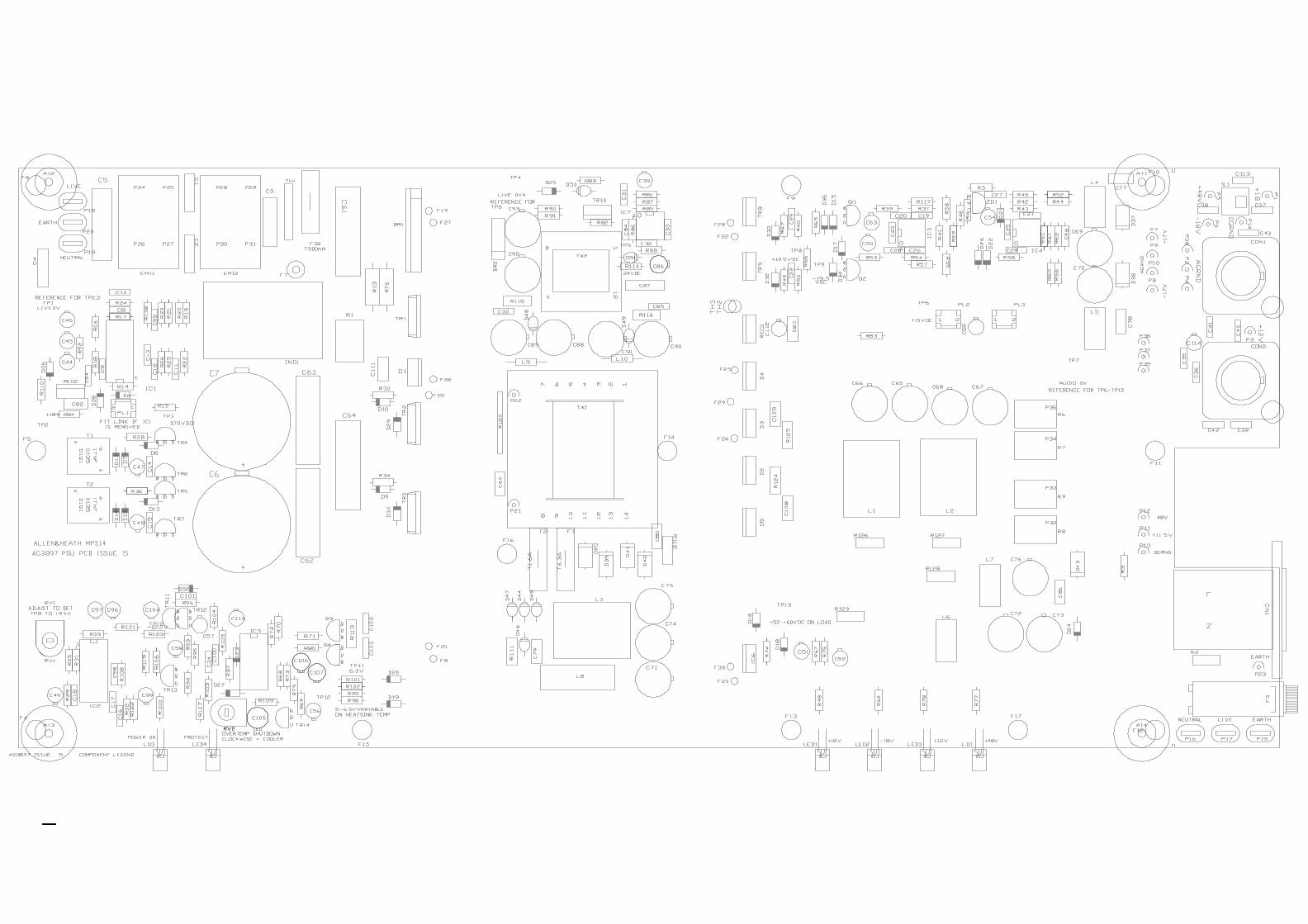
duncanda
D83
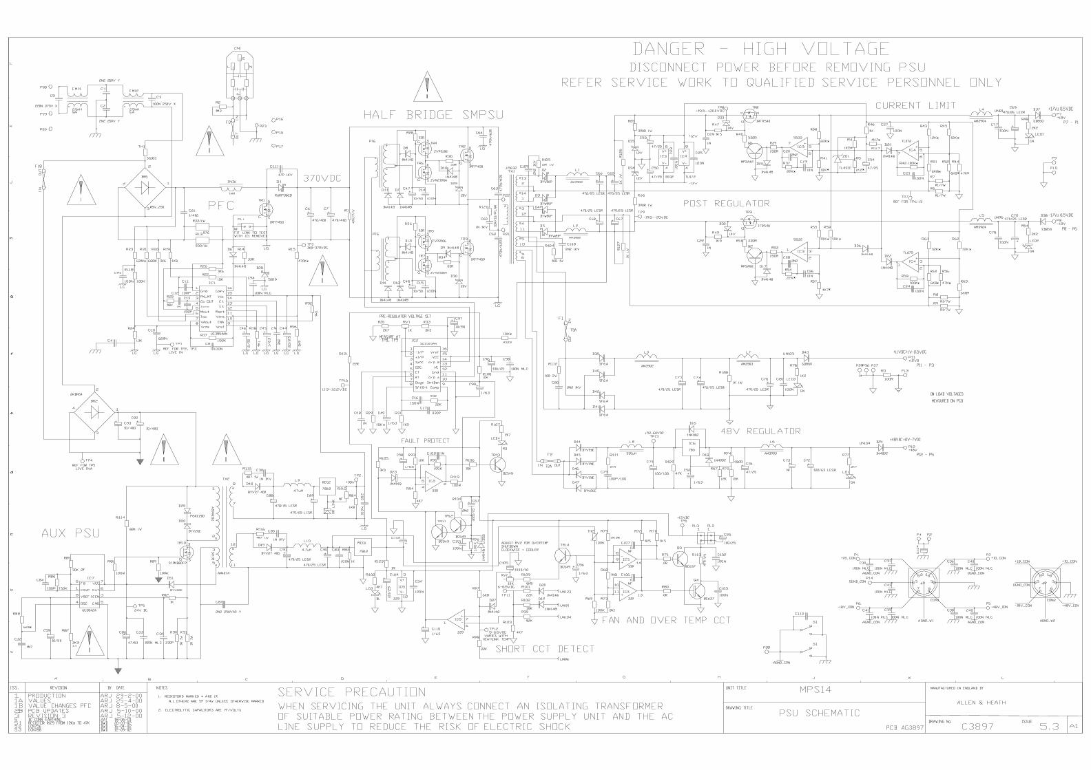
duncanda
D84

duncanda
D85

duncanda
D86

duncanda
D87

Allen & HeathKernick Industrial Estate,Penryn, Cornwall,England.TR10 9LUTel: (44) (0) 1326 372070Fax: (44) (0) 1326 365736
2.1
ML5000 SYSLINK II OUT
C4013 1 2
PAGE:
TITLE:
NO.: ISSUE: SHEET OF
ISSUE BY DATE
FILE: DISK:G:\Product Directories\ML5000\PCB\ML5KSYSLINK II OUT4013_2.1\SYSLINKOUT.ddb - Documents\AG4013 ISSUE 2.1\C4013_2.1 p2.Sch13:43:01 3-Dec-2002 A3Error : A&hlogo.wmf file not found.
Error : harman.WMF file not found.A Division ofHarman International Industries Limited
120
221
322
423
524
625
726
827
92810291130123113321433153416351736183719
J3
DB37
3
21
U24A
TL072
5
67
U24B
TL072V-
4V
+8
U24C
TL072
R115
10k
R116
10k
R117
10k
R231
68R
R232
68R
R118
10k
R119
10k
R28247k
C24
1000/6.3
C84
47p
C85
47pGND
GND GND
+V
-V
3
21
U25A
TL072
5
67
U25B
TL072V-
4V
+8
U25C
TL072
R120
10k
R121
10k
R122
10k
R233
68R
R234
68R
R123
10k
R124
10k
R28347k
C25
1000/6.3
C86
47p
C87
47pGND
GND GND
+V
-V
3
21
U26A
TL072
5
67
U26B
TL072V-
4V
+8
U26C
TL072
R125
10k
R126
10k
R127
10k
R235
68R
R236
68R
R128
10k
R129
10k
R28447k
C26
1000/6.3
C88
47p
C89
47pGND
GND GND
+V
-V
3
21
U27A
TL072
5
67
U27B
TL072V-
4V
+8
U27C
TL072
R130
10k
R131
10k
R132
10k
R237
68R
R238
68R
R133
10k
R134
10k
R28547k
C27
1000/6.3
C90
47p
C91
47pGND
GND GND
+V
-V
3
21
U28A
TL072
5
67
U28B
TL072V-
4V
+8
U28C
TL072
R135
10k
R136
10k
R137
10k
R239
68R
R240
68R
R138
10k
R139
10k
R28647k
C28
1000/6.3
C92
47p
C93
47pGND
GND GND
+V
-V
3
21
U29A
TL072
5
67
U29B
TL072V-
4V
+8
U29C
TL072
R140
10k
R141
10k
R142
10k
R241
68R
R242
68R
R143
10k
R144
10k
R28747k
C29
1000/6.3
C94
47p
C95
47pGND
GND GND
+V
-V
3
21
U30A
TL072
5
67
U30B
TL072V-
4V
+8
U30C
TL072
R145
10k
R146
10k
R147
10k
R243
68R
R244
68R
R148
10k
R149
10k
R28847k
C30
1000/6.3
C96
47p
C97
47pGND
GND GND
+V
-V
3
21
U31A
TL072
5
67
U31B
TL072V-
4V
+8
U31C
TL072
R150
10k
R151
10k
R152
10k
R245
68R
R246
68R
R153
3K9
R154
10k
R28947k
C31
1000/6.3
C98
47p
C99
47pGND
GND GND
+V
-V
3
21
U32A
TL072
5
67
U32B
TL072V-
4V
+8
U32C
TL072
R155
10k
R156
10k
R157
10k
R247
68R
R248
68R
R297
100R
R158
10k
R159
10k
R29047k
C32
1000/6.3
C100
47p
C101
47pGND
GND GND
+V
-V
3
21
U33A
TL072
5
67
U33B
TL072V-
4V
+8
U33C
TL072
R160
10k
R161
10k
R162
10k
R249
68R
R250
68R
R163
10k
R164
10k
R29147k
C33
1000/6.3
C102
47p
C103
47pGND
GND GND
+V
-V
3
21
U34A
TL072
5
67
U34B
TL072V-
4V
+8
U34C
TL072
R165
10k
R166
10k
R167
10k
R251
68R
R252
68R
R168
10k
R169
10k
R29247k
C34
1000/6.3
C104
47p
C105
47pGND
GND GND
+V
-V
3
21
U35A
TL072
5
67
U35B
TL072V-
4V
+8
U35C
TL072
R170
10k
R171
10k
R172
10k
R253
68R
R254
68R
R173
10k
R174
10k
R29347k
C35
1000/6.3
C106
47p
C107
47pGND
GND GND
+V
-V
3
21
U36A
TL072
5
67
U36B
TL072V-
4V
+8
U36C
TL072
R175
10k
R176
10k
R177
10k
R255
68R
R256
68R
R178
10k
R179
10k
R29447k
C36
1000/6.3
C108
47p
C109
47pGND
GND GND
+V
-V
3
21
U37A
TL072
5
67
U37B
TL072V-
4V
+8
U37C
TL072
R180
10k
R181
10k
R182
10k
R257
68R
R258
68R
R183
3K9
R184
10k
R29547k
C37
1000/6.3
C110
47p
C111
47pGND
GND GND
+V
-V
123456789
1011121314151617181920212223242526272829303132333435363738394041424344454647484950
J4
CON50
pfl+pfl-
p/paux6+p/paux6-p/paux5+p/paux5-p/paux4+p/paux4-p/paux3+p/paux3-p/paux2+p/paux2-p/paux1+p/paux1-
grp4+grp4-grp3+grp3-grp2+grp2-grp1+grp1-mixr+mixr-mixl+mixl-
AFL_L+
AFL_L-
pfl+
pfl-
p/paux6+
p/paux6-
p/paux5+
p/paux5-
p/paux4+
p/paux4-
p/paux3+
p/paux3-
p/paux2+
p/paux2-
p/paux1+
p/paux1-
grp4-
grp4+
grp3-
grp3+
grp2-
grp2+
grp1-
grp1+
mixr-
mixr+
mixl-
mixl+
G.C.
G.C.
G.C.
G.C.
G.C.
G.C.
G.C.
G.C.
G.C.
G.C.
G.C.
G.C.
G.C.
G.C.
lmix
rmix
grp1mix
grp2mix
grp3mix
grp4mix
p/paux1mix
p/paux2mix
p/paux3mix
p/paux4mix
p/paux5mix
p/paux6mix
PFL_BUS
AFLL_BUS
grp1mixpoaux1mixp/paux1mixgrp2mixpoaux2mixp/paux2mixgrp3mixpoaux3mix
grp4mixpoaux4mixp/paux4mixgrp5mixpoaux5mixp/paux5mixgrp6mixpoaux6mixp/paux6mixgrp7mixpoaux7mixp/paux7mixgrp8mixpoaux8mixp/paux8mixaux9mixaux10mixaux11mixaux12mixaux13mixaux14mixaux15mixaux16mix
PFL_BUSAFLL_BUScmixlmixrmix
p/paux3mix
R29810R
R29910R
C11247/25
C11347/25
C114
100n
+V
-V
GND
GND
G.C.
D11N4002
D21N4002
+ IN- IN
0V IN
AAT 06-06-001A GMR
R3000R
48V IN
D0V IN
P1
48V
P2
-18V
P3
+18V
P4
AGND
P5
LG
AAT 05-09-002.1
duncanda
Error : harman.WMF A Division of Harman International
duncanda
WMF file not found. of International Industries Limited
duncanda
D88

Allen & HeathKernick Industrial Estate,Penryn, Cornwall,England.TR10 9LUTel: (44) (0) 1326 372070Fax: (44) (0) 1326 365736
2.1
ML5000 SYSLINK II OUT
C4013 2 1
PAGE:
TITLE:
NO.: ISSUE: SHEET OF
ISSUE BY DATE
FILE: DISK:G:\Product Directories\ML5000\PCB\ML5KSYSLINK II OUT4013_2.1\SYSLINKOUT.ddb - Documents\AG4013 ISSUE 2.1\C4013_2.1 p3.Sch13:43:02 3-Dec-2002 A3Error : A&hlogo.wmf file not found.
Error : harman.WMF file not found.A Division ofHarman International Industries Limited
120
221
322
423
524
625
726
827
92810291130123113321433153416351736183719
J1DB37
120
221
322
423
524
625
726
827
92810291130123113321433153416351736183719
J2
DB37
3
21
U1A
TL072
5
67
U1B
TL072V-
4V
+8
U1C
TL072
R1
10k
R2
10k
R3
10k
R185
68R
R186
68R
R4
10k
R5
10k
R25947k
C1
1000/6.3
C38
47p
C39
47pGND
GND GND
+V
-V
3
21
U2A
TL072
5
67
U2B
TL072V-
4V
+8
U2C
TL072
R6
10k
R7
10k
R8
10k
R187
68R
R188
68R
R9
10k
R10
10k
R26047k
C2
1000/6.3
C40
47p
C41
47pGND
GND GND
+V
-V
3
21
U3A
TL072
5
67
U3B
TL072V-
4V
+8
U3C
TL072
R11
10k
R12
10k
R13
10k
R189
68R
R190
68R
R14
10k
R15
10k
R26147k
C3
1000/6.3
C42
47p
C43
47pGND
GND GND
+V
-V
3
21
U4A
TL072
5
67
U4B
TL072V-
4V
+8
U4C
TL072
R16
10k
R17
10k
R18
10k
R191
68R
R192
68R
R19
10k
R20
10k
R26247k
C4
1000/6.3
C44
47p
C45
47pGND
GND GND
+V
-V
3
21
U5A
TL072
5
67
U5B
TL072V-
4V
+8
U5C
TL072
R21
10k
R22
10k
R23
10k
R193
68R
R194
68R
R24
10k
R25
10k
R26347k
C5
1000/6.3
C46
47p
C47
47pGND
GND GND
+V
-V
3
21
U6A
TL072
5
67
U6B
TL072V-
4V
+8
U6C
TL072
R26
10k
R27
10k
R28
10k
R195
68R
R196
68R
R29
10k
R30
10k
R26447k
C6
1000/6.3
C48
47p
C49
47pGND
GND GND
+V
-V
3
21
U7A
TL072
5
67
U7B
TL072V-
4V
+8
U7C
TL072
R31
10k
R32
10k
R33
10k
R197
68R
R198
68R
R34
10k
R35
10k
R26547k
C7
1000/6.3
C50
47p
C51
47pGND
GND GND
+V
-V
3
21
U8A
TL072
5
67
U8B
TL072V-
4V
+8
U8C
TL072
R36
10k
R37
10k
R38
10k
R199
68R
R200
68R
R39
10k
R40
10k
R26647k
C8
1000/6.3
C52
47p
C53
47pGND
GND GND
+V
-V
3
21
U9A
TL072
5
67
U9B
TL072V-
4V
+8
U9C
TL072
R41
10k
R42
10k
R43
10k
R201
68R
R202
68R
R44
10k
R45
10k
R26747k
C9
1000/6.3
C54
47p
C55
47pGND
GND GND
+V
-V
3
21
U10A
TL072
5
67
U10B
TL072V-
4V
+8
U10C
TL072
R46
10k
R47
10k
R48
10k
R203
68R
R204
68R
R49
10k
R50
10k
R26847k
C10
1000/6.3
C56
47p
C57
47pGND
GND GND
+V
-V
3
21
U11A
TL072
5
67
U11B
TL072V-
4V
+8
U11C
TL072
R51
10k
R52
10k
R53
10k
R205
68R
R206
68R
R54
10k
R55
10k
R26947k
C11
1000/6.3
C58
47p
C59
47pGND
GND GND
+V
-V
3
21
U12A
TL072
5
67
U12B
TL072V-
4V
+8
U12C
TL072
R56
10k
R57
10k
R58
10k
R207
68R
R208
68R
R59
10k
R60
10k
R27047k
C12
1000/6.3
C60
47p
C61
47pGND
GND GND
+V
-V
3
21
U13A
TL072
5
67
U13B
TL072V-
4V
+8
U13C
TL072
R61
10k
R62
10k
R63
10k
R209
68R
R210
68R
R64
10k
R65
10k
R27147k
C13
1000/6.3
C62
47p
C63
47pGND
GND GND
+V
-V
3
21
U14A
TL072
5
67
U14B
TL072V-
4V
+8
U14C
TL072
R66
10k
R67
10k
R68
10k
R211
68R
R212
68R
R69
10k
R70
10k
R27247k
C14
1000/6.3
C64
47p
C65
47pGND
GND GND
+V
-V
3
21
U15A
TL072
5
67
U15B
TL072V-
4V
+8
U15C
TL072
R71
10k
R72
10k
R73
10k
R213
68R
R214
68R
R74
10k
R75
10k
R27347k
C15
1000/6.3
C66
47p
C67
47pGND
GND GND
+V
-V
3
21
U16A
TL072
5
67
U16B
TL072V-
4V
+8
U16C
TL072
R76
10k
R77
10k
R78
10k
R215
68R
R216
68R
R296
3k9
R79
10k
R27447k
C16
1000/6.3
C68
47p
C69
47pGND
GND GND
+V
-V
3
21
U17A
TL072
5
67
U17B
TL072V-
4V
+8
U17C
TL072
R80
10k
R81
10k
R82
10k
R217
68R
R218
68R
R83
10k
R84
10k
R27547k
C17
1000/6.3
C70
47p
C71
47pGND
GND GND
+V
-V
3
21
U18A
TL072
5
67
U18B
TL072V-
4V
+8
U18C
TL072
R85
10k
R86
10k
R87
10k
R219
68R
R220
68R
R88
10k
R89
10k
R27647k
C18
1000/6.3
C72
47p
C73
47pGND
GND GND
+V
-V
3
21
U19A
TL072
5
67
U19B
TL072V-
4V
+8
U19C
TL072
R90
10k
R91
10k
R92
10k
R221
68R
R222
68R
R93
10k
R94
10k
R27747k
C19
1000/6.3
C74
47p
C75
47pGND
GND GND
+V
-V
3
21
U20A
TL072
5
67
U20B
TL072V-
4V
+8
U20C
TL072
R95
10k
R96
10k
R97
10k
R223
68R
R224
68R
R98
10k
R99
10k
R27847k
C20
1000/6.3
C76
47p
C77
47pGND
GND GND
+V
-V
3
21
U21A
TL072
5
67
U21B
TL072V-
4V
+8
U21C
TL072
R100
10k
R101
10k
R102
10k
R225
68R
R226
68R
R103
10k
R104
10k
R27947k
C21
1000/6.3
C78
47p
C79
47pGND
GND GND
+V
-V
3
21
U22A
TL072
5
67
U22B
TL072V-
4V
+8
U22C
TL072
R105
10k
R106
10k
R107
10k
R227
68R
R228
68R
R108
10k
R109
10k
R28047k
C22
1000/6.3
C80
47p
C81
47pGND
GND GND
+V
-V
3
21
U23A
TL072
5
67
U23B
TL072V-
4V
+8
U23C
TL072
R110
10k
R111
10k
R112
10k
R229
68R
R230
68R
R113
10k
R114
10k
R28147k
C23
1000/6.3
C82
47p
C83
47pGND
GND GND
+V
-V
poaux5-
poaux4-
poaux5+
poaux4+poaux5-
poaux6-
poaux6+
poaux5+poaux6-
poaux7-
poaux7+
poaux6+poaux7-
poaux8-
poaux8+
poaux7+poaux8-poaux8+
poaux4-
poaux4+
poaux3-
poaux3-poaux3+
poaux2+
poaux2+
poaux3+
poaux2-
poaux2-poaux1+
poaux1+
poaux1-
poaux1-
G.C.
G.C.
G.C.
G.C.
G.C.
G.C.
G.C.
G.C.
poaux8mix
poaux7mix
poaux6mix
poaux5mix
poaux4mix
poaux3mix
poaux2mix
poaux1mix
aux16-aux16+
aux15-aux15+
aux14+aux14-aux13+aux13-
aux12+
aux12-
aux11+
aux11-aux10+aux10-aux9+aux9-
p/paux8+p/paux8-p/paux7+p/paux7-
grp8+grp8-grp7+grp7-grp6+grp6-grp5+grp5-
mixc+mixc-
aux16-
aux16+
aux14-
aux14+
aux12-
aux12+
aux10-
aux10+
aux15-
aux15+
aux13-
aux13+
aux11-
aux11+
aux9-
aux9+
p/paux8-
p/paux8+
p/paux7-
p/paux7+
grp8-
grp8+
grp7-
grp7+
grp6-
grp6+
grp5-
grp5+
mixc-
mixc+
G.C.
G.C.
G.C.
G.C.
G.C.
G.C.
G.C.
G.C.
G.C.
G.C.
G.C.
G.C.
G.C.
G.C.
G.C.
grp5mix
grp6mix
grp7mix
grp8mix
Cmix
p/paux7mix
p/paux8mix
aux9mix
aux10mix
aux11mix
aux12mix
aux13mix
aux14mix
aux15mix
aux16mix
AFL_L+AFL_L-
AAT 06-06-001A GMR
AAT 05-09-002.1
duncanda
Error : harman.WMF A Division of Harman International
duncanda
WMF file not found. International Industries Limited
duncanda
D89