Mini-Rooter Pro Operating Instructions
12
Mini-Rooter Pro ™ Operating Instructions For 1-1/4” through 4” lines (30mm—100mm) Your Mini-Rooter Pro is designed to give you years of trouble-free, profitable service. However, no machine is better than its operator. Read, understand and follow all safety warnings and instructions provided with the product. Failure to follow the warnings and instructions may result in electric shock and/or serious injury. Save all warn- ings and instructions for future reference. SAVE THESE INSTRUCTIONS!
-
Upload
khangminh22 -
Category
Documents
-
view
2 -
download
0
Transcript of Mini-Rooter Pro Operating Instructions

Mini-Rooter Pro™
Operating Instructions
For 1-1/4” through 4” lines (30mm—100mm)
Your Mini-Rooter Pro is designed to
give you years of trouble-free, profitable
service. However, no machine is better
than its operator.
Read, understand and follow all safety
warnings and instructions provided with
the product. Failure to follow the warnings
and instructions may result in electric
shock and/or serious injury. Save all warn-
ings and instructions for future reference.
SAVE THESE INSTRUCTIONS!

WARNING! Read and understand all instructions. Failure to follow all instructions listed below may result in electric shock, fire and/or serious personal injury. Replacement manuals are available upon request at no charge, or may be downloaded from our web-site, www.drainbrain.com. Instructional videos are available for download on our website, and may be ordered. If you have any questions or problems, please call General’s customer service department at 412-771-6300.
SAVE THESE INSTRUCTIONS!
SAFETY SYMBOLS
Mini-Rooter Pro™
Electric shock resulting in death can occur if you plug this machine into an improp-erly wired outlet. If the ground wire is electrified, you can be electrocuted by just touching the machine, even when the power switch is off. A ground fault circuit interrupter will not pro-tect you in this situation. Use a UL approved tester to determine if the outlet is safe.
Do not operate power tools in explosive atmospheres, such as in the presence of flamma-ble liquids, gases, or dust. Power tools create sparks which may ignite dust or fumes.
Only wear leather gloves. Never use any other type of glove, such as cloth, rubber, or coated gloves. Never grasp a rotating cable with a rag. These items could become wrapped around the cable and cause serious injury.
Always wear safety glasses and rubber soled, non-slip shoes. Use of this safety equip-ment may prevent serious injury.
Never operate machine with belt guard removed. Fingers can get caught between belt and pulley.
Do not overstress cables. Overstressing cables may cause twisting, kinking, or breaking of the cable and may result in seri-ous injury.
These instructions are intended to familiarize all personnel with the safe
operation and maintenance procedures for the Mini-Rooter Pro.
DANGER indicates a hazard with a high level of risk
which, if not avoided, will result in death or serious injury.
WARNING indicates a hazard with a medium level of risk
which, if not avoided, could result in death or serious injury.
CAUTION indicates a hazard with a low level of risk which,
if not avoided, will result in minor or moderate injury.
This is the safety alert symbol. It is used to alert you to potential personal injury hazards. Obey all safety mes-sages that follow this symbol to avoid possible injury or death.
2

Mini-Rooter Pro™
3
Work Area
1. Keep work area clean and well lit. Cluttered benches and dark
areas invite accidents.
2. Do not operate power tools in explosive atmospheres, such as in the presence of flammable liquids, gases, or dust. Power
tools create sparks which may ignite the dust or fumes.
3. Keep bystanders, children, and visitors away while operating a power tool. Distractions can cause you to lose control.
Electrical Safety 1. Grounded tools must be plugged into an outlet, properly in-
stalled and grounded in accordance with all codes and ordi-nances. Never remove the grounding prong or modify the plug in any way. Do not use any adapter plugs. Check with a qualified electrician if you are in doubt as to whether the out-let is properly grounded. If the tool should electrically malfunc-tion or break down, grounding provides a low resistance path to
carry electricity away from the user.
2. Avoid body contact with grounded surfaces such as pipes, radiators, ranges and refrigerators. There is an increased risk of
electric shock if your body is grounded.
3. Do not expose power tools to rain or wet conditions. Water
entering a power tool will increase the risk of electric shock.
4. Do not abuse the cord. Never use the cord to carry the tools or pull the plug from an outlet. Keep cord away from heat, oil, sharp edges or moving parts. Replace damaged cords imme-
diately. Damaged cords increase the risk of electric shock.
5. When operating a power tool outside use an outdoor exten-sion cord marked “W-A” or “W”. These cords are rated for out-
door use and reduce the risk of electric shock.
6. Test the Ground Fault Circuit Interrupter (GFCI) provided with the power cord to insure it is operating correctly before oper-ating machine. Machine must have a properly functioning ground fault circuit interrupter on the power cord. GFCI reduces the risk of
electric shock.
7. Extension cords are not recommended unless they are plugged into a Ground Fault Circuit Interrupter (GFCI) found in circuit boxes or outlet receptacles. The GFCI on the machine power cord will not prevent electric shock from the extension
cords.
8. Only use proper three-wire extension cords in good condition which have three-prong grounding plugs and three-pole re-ceptacles which accept the tool’s plug. Use of damaged, infe-rior, or other extension cords will not ground the tool. Increases
the risk of electric shock and bodily injury or death.
9. Keep all electric connections dry and off the ground. Reduces
the risk of electric shock.
10. DO NOT touch plugs or tools with wet hands. Reduces the risk of electric shock.
Personal Safety 1. Stay alert, watch what you are doing and use common sense
when operating a power tool. Do not use tool while tired or under the influence of drugs, alcohol, or medication. A mo-ment of inattention while operating power tools may result in seri-
ous personal injury.
2. Dress properly. Do not wear loose clothing or jewelry. Con-tain long hair. Keep your hair, clothing, and gloves away from moving parts. Loose clothes, jewelry, or long hair can be
caught in moving parts.
3. Avoid accidental starting. Be sure switch is off before plug-ging in. Carrying tools with your finger on the switch or plugging in
tools that have the switch on invites accidents.
4. Remove adjusting keys or switches before turning the tool on. A wrench or key that is left attached to a rotating part of the
tool may result in personal injury.
5. Do not overreach. Keep proper footing and balance at all times. Proper footing and balance enables better control of the
tool in unexpected situations.
6. Use safety equipment. Always wear eye protection. Dust mask, non-skid safety shoes, hard hat, or hearing protection must be used for appropriate conditions.
Tool Use and Care 1. Use clamps or other practical way to secure and support the
workpiece to a stable platform. Holding the work by hand or
against your body is unstable and may lead to loss of control.
2. Do not force tool. Use the correct tool for your application. The correct tool will do the job better and safer at the rate for
which it is designed.
3. Do not use tool if switch does not turn it on or off. Any tool that cannot be controlled with the switch is dangerous and must
be repaired.
4. Disconnect the plug from the power source before making any adjustments, changing accessories, or storing the tool. Such preventative safety measures reduce the risk of starting the
tool accidentally.
5. Store idle tools out of reach of children and other untrained
persons. Tools are dangerous in the hands of untrained users.
6. Maintain tools with care. Keep cutting tools sharp and clean. Properly maintained tools, with sharp cutting edges are less likely
to bind and are easier to control.
7. Check for misalignment or binding of moving parts, breakage of parts, and any other condition that may affect the tool’s operation. If damaged, have the tool serviced before using.
Many accidents are caused by poorly maintained tools.
8. Only use accessories that are recommended by the manufac-turer for your model. Accessories that may be suitable for one tool may become hazardous when used on another tool.
Service 1. Tool service must be performed only by qualified repair per-
sonnel. Service or maintenance performed by unqualified repair
personnel could result in risk of injury.
2. When servicing a tool, use only identical replacement parts. Follow instructions in the Maintenance section of this man-ual. Use of unauthorized parts or failure to follow Maintenance Instructions may create a risk of electric shock or injury.
GENERAL SAFETY RULES
WARNING
Read and understand all instructions. Failure to follow all in-structions listed below may result in electric shock, fire, and/or serious injury.
SAVE THESE INSTRUCTIONS!
Mini-Rooter Pro™
4
THE SECTION OF CORD BETWEEN THE WALL PLUG
AND THE GFCI IS NOT IN THE PROTECTED CIRCUIT.
1. Only wear leather gloves. Never use any other type of glove, such as cloth, rubber, or coated gloves. Never grasp a rotating cable with a rag. These items could become wrapped around the
cable and cause serious injury.
2. Never operate machine with belt guard removed. Fingers can
get caught between belt and pulley.
3. Do not overstress cables. Keep leather-gloved hand on the ca-ble for control when machine is running. Overstressing cables because of an obstruction may cause twisting, kinking, or breaking
of the cable and may result in serious injury.
4. Place the machine at a distance not greater than two feet from the opening. Greater distances can result in cable twisting or
kinking.
5. Machine is designed for ONE-PERSON operation. Operator
must control foot switch and cable.
6. Do not operate machine in reverse (REV). Operating machine in reverse can result in cable damage and is used only to back
cutting tool out of an obstruction.
7. Keep hands away from rotating drum. Do not reach into drum unless machine is unplugged. Hand may be caught in the moving
parts resulting in serious injury.
8. Be careful when cleaning drains where cleaning chemicals have been used. Avoid direct contact with skin and eyes. Drain cleaning chemicals can cause serious burns as well as damage
the cable.
9. Do not operate machine if operator or machine is standing in
water. Will increase risk of electrical shock.
10. Wear safety glasses and rubber soled, non-slip shoes. Use of
this safety equipment may prevent serious injury.
11. Before starting each job, check that the cable in the drum is not broken or kinked, by pulling the cable out and checking for wear or breakage. Always replace worn out (kinked or bro-
ken) cables with genuine GENERAL replacement cables.
12. Only use this tool in the application for which it was de-signed. Follow the instructions on the proper use of the ma-chine. Other uses or modifying the drain cleaner for other applica-tions may increase risk of injury.
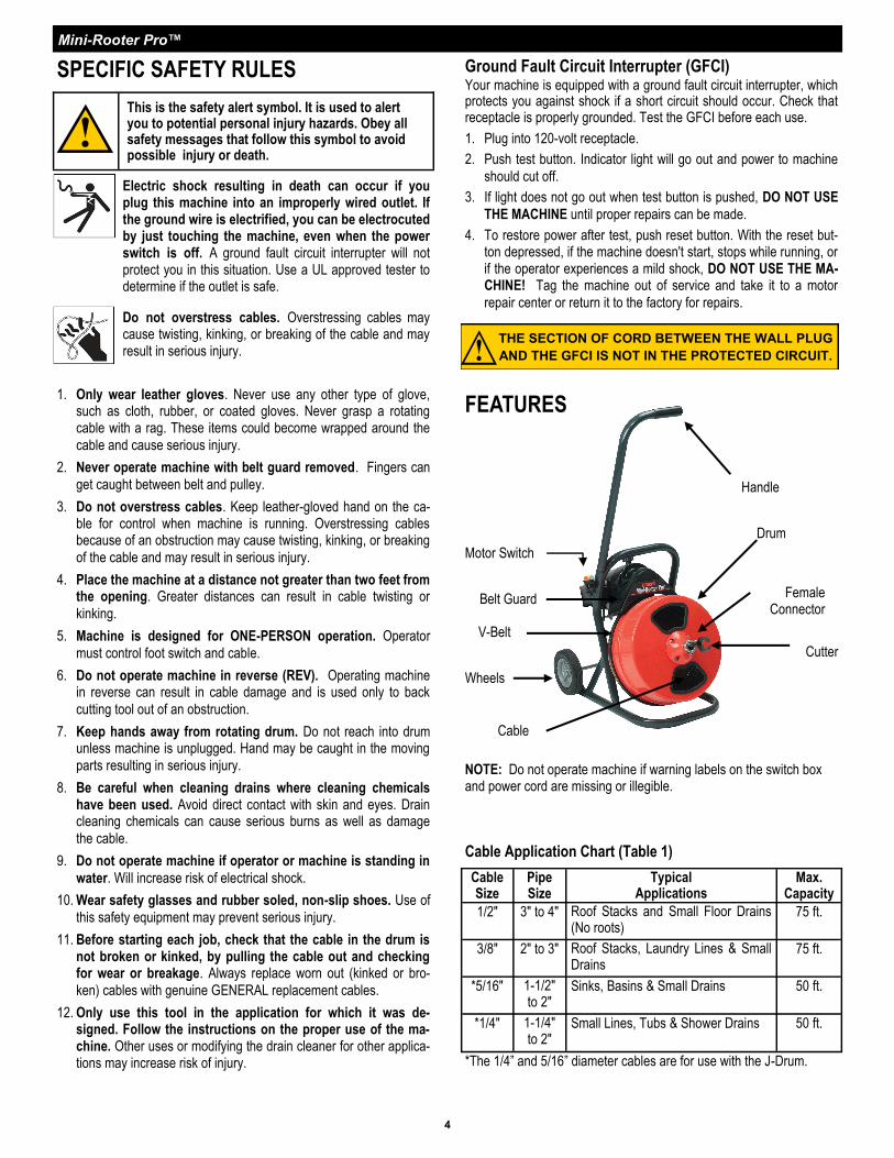
Motor Switch
Female Connector
Cutter
Belt Guard
V-Belt
Drum
Cable
Cable Application Chart (Table 1)
Cable Size
Pipe Size
Typical Applications
Max. Capacity
1/2" 3" to 4" Roof Stacks and Small Floor Drains (No roots)
75 ft.
3/8" 2" to 3" Roof Stacks, Laundry Lines & Small Drains
75 ft.
*5/16" 1-1/2" to 2"
Sinks, Basins & Small Drains 50 ft.
*1/4" 1-1/4" to 2"
Small Lines, Tubs & Shower Drains 50 ft.
*The 1/4” and 5/16” diameter cables are for use with the J-Drum.
Ground Fault Circuit Interrupter (GFCI) Your machine is equipped with a ground fault circuit interrupter, which protects you against shock if a short circuit should occur. Check that receptacle is properly grounded. Test the GFCI before each use.
1. Plug into 120-volt receptacle.
2. Push test button. Indicator light will go out and power to machine
should cut off.
3. If light does not go out when test button is pushed, DO NOT USE
THE MACHINE until proper repairs can be made.
4. To restore power after test, push reset button. With the reset but-ton depressed, if the machine doesn't start, stops while running, or if the operator experiences a mild shock, DO NOT USE THE MA-CHINE! Tag the machine out of service and take it to a motor
repair center or return it to the factory for repairs.
NOTE: Do not operate machine if warning labels on the switch box and power cord are missing or illegible.
SPECIFIC SAFETY RULES
This is the safety alert symbol. It is used to alert you to potential personal injury hazards. Obey all safety messages that follow this symbol to avoid possible injury or death.
Electric shock resulting in death can occur if you plug this machine into an improperly wired outlet. If the ground wire is electrified, you can be electrocuted by just touching the machine, even when the power switch is off. A ground fault circuit interrupter will not protect you in this situation. Use a UL approved tester to determine if the outlet is safe.
Do not overstress cables. Overstressing cables may cause twisting, kinking, or breaking of the cable and may result in serious injury.
Handle
Wheels
FEATURES
Mini-Rooter Pro™
OPERATING INSTRUCTIONS Set-Up
1. Place machine within approximately two feet (.6m) of drain open-
ing. If you can’t place the machine this close to the drain opening,
run the cable through a metal guide tube to prevent cable whip-
ping.
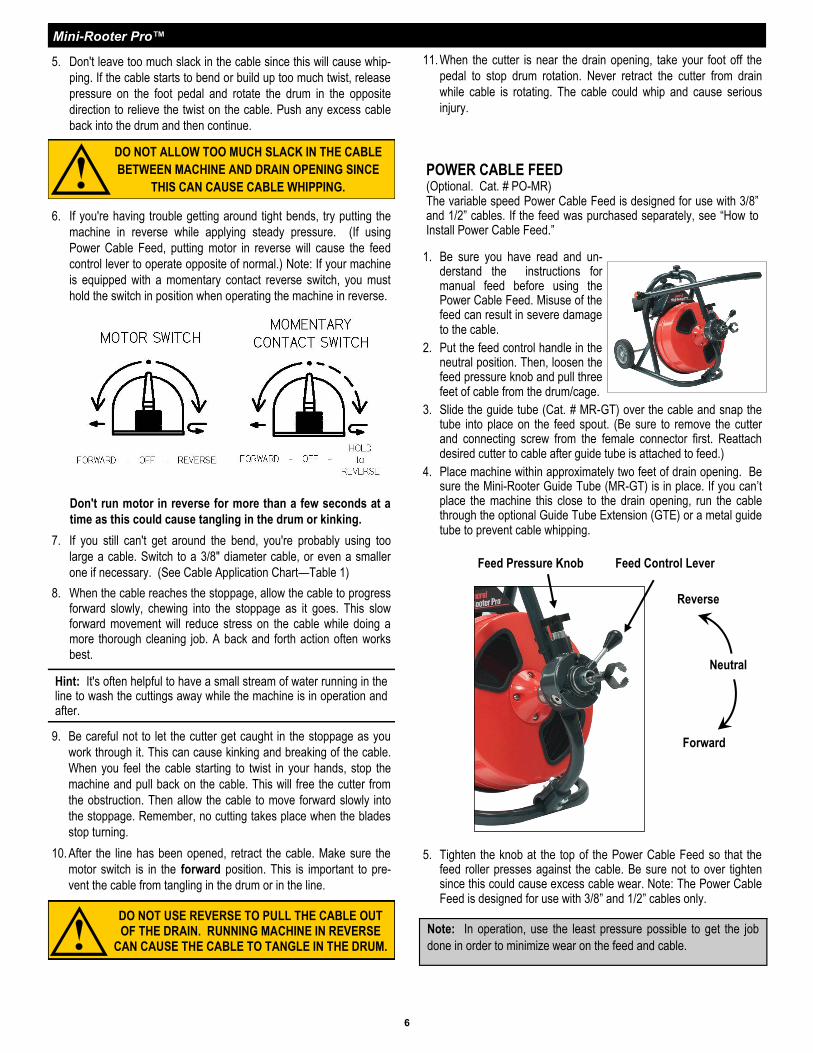
2. Position the foot pedal for easy acces-
sibility. The machine is designed for
one-person operation. Be sure you
can quickly remove your foot from the
pedal in an emergency.
3. Be sure the motor switch is in the off
position.
4. Select the proper cutting tool (See Cutter Application Chart—Table
2). A good tool to start with is the Arrow Head or Boring Gimlet.
After the line is opened, follow with larger blades, which scrape
the inside edges of the pipe, assuring a real cleaning job.
5. Insert the cutter into the female connector at the end of the 3/8" or 1/2" cable and tighten the connecting screw and lock washer firmly in place.
DO NOT USE TOO MUCH FORCE – LET THE CUTTER DO THE WORK.
5
Operation 1. Begin by pulling the cable from the drum/cage and sliding it into
the drain as far as it will go.
2. Move the motor switch to the forward position.
3. With both hands (wearing leather gloves) on the cable, depress
the air foot pedal to start machine.
4. Feed the cable into the line and against the obstruction with a firm,
even pressure. Adjust the feeding rate to the resistance met. Do
not force the cable – let the cutter do the work. The job won’t get
done any faster and you could damage the cable.
Cutter Application Chart (Table 2)
Cutter Cat. # Typical Applications
Cutters for 3/8” and 1/2”Cables
Arrow
Head
AH Starting tool, ideal for cutting and scraping.
Boring
Gimlet
BG Starting tool, to remove loose objects.
1-1/2” U-Cutter
1-1/2UC Finishing tool, works well in grease stoppages.
2” Side Cutter
Blade
2SCB Finishing tool, for scraping inside edges of pipe.
Note: There are no fixed rules for what cutter to use. If one tool does not take care of a stoppage, simply try another.
MAKE SURE THE MOTOR SWITCH IS IN THE ‘OFF’ POSITION!
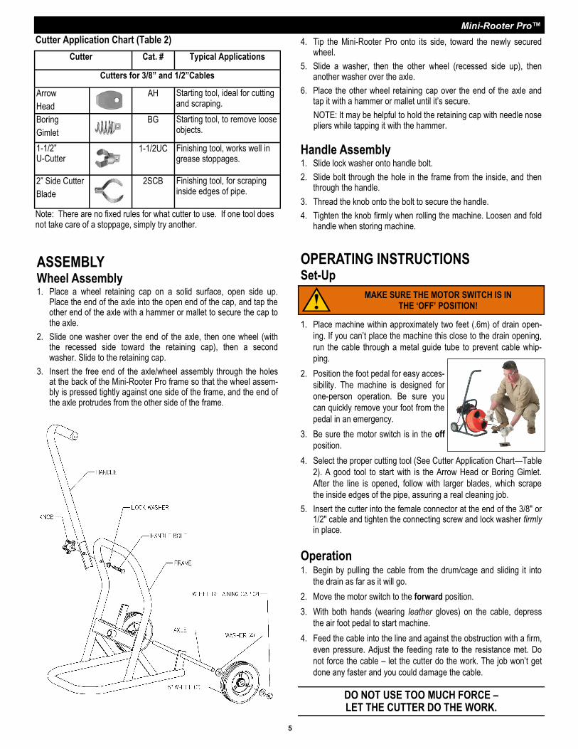
ASSEMBLY Wheel Assembly 1. Place a wheel retaining cap on a solid surface, open side up.
Place the end of the axle into the open end of the cap, and tap the other end of the axle with a hammer or mallet to secure the cap to the axle.
2. Slide one washer over the end of the axle, then one wheel (with the recessed side toward the retaining cap), then a second washer. Slide to the retaining cap.
3. Insert the free end of the axle/wheel assembly through the holes at the back of the Mini-Rooter Pro frame so that the wheel assem-bly is pressed tightly against one side of the frame, and the end of the axle protrudes from the other side of the frame.
4. Tip the Mini-Rooter Pro onto its side, toward the newly secured wheel.
5. Slide a washer, then the other wheel (recessed side up), then another washer over the axle.
6. Place the other wheel retaining cap over the end of the axle and tap it with a hammer or mallet until it’s secure.
NOTE: It may be helpful to hold the retaining cap with needle nose pliers while tapping it with the hammer.
Handle Assembly 1. Slide lock washer onto handle bolt.
2. Slide bolt through the hole in the frame from the inside, and then through the handle.
3. Thread the knob onto the bolt to secure the handle.
4. Tighten the knob firmly when rolling the machine. Loosen and fold handle when storing machine.
Mini-Rooter Pro™
6
5. Don't leave too much slack in the cable since this will cause whip-
ping. If the cable starts to bend or build up too much twist, release
pressure on the foot pedal and rotate the drum in the opposite
direction to relieve the twist on the cable. Push any excess cable
back into the drum and then continue.
6. If you're having trouble getting around tight bends, try putting the
machine in reverse while applying steady pressure. (If using
Power Cable Feed, putting motor in reverse will cause the feed
control lever to operate opposite of normal.) Note: If your machine
is equipped with a momentary contact reverse switch, you must
hold the switch in position when operating the machine in reverse.
Don't run motor in reverse for more than a few seconds at a
time as this could cause tangling in the drum or kinking.
7. If you still can't get around the bend, you're probably using too
large a cable. Switch to a 3/8" diameter cable, or even a smaller
one if necessary. (See Cable Application Chart—Table 1)
8. When the cable reaches the stoppage, allow the cable to progress forward slowly, chewing into the stoppage as it goes. This slow forward movement will reduce stress on the cable while doing a more thorough cleaning job. A back and forth action often works
best.
Hint: It's often helpful to have a small stream of water running in the line to wash the cuttings away while the machine is in operation and after.
DO NOT USE REVERSE TO PULL THE CABLE OUT OF THE DRAIN. RUNNING MACHINE IN REVERSE
CAN CAUSE THE CABLE TO TANGLE IN THE DRUM.
9. Be careful not to let the cutter get caught in the stoppage as you
work through it. This can cause kinking and breaking of the cable.
When you feel the cable starting to twist in your hands, stop the
machine and pull back on the cable. This will free the cutter from
the obstruction. Then allow the cable to move forward slowly into
the stoppage. Remember, no cutting takes place when the blades
stop turning.
10. After the line has been opened, retract the cable. Make sure the
motor switch is in the forward position. This is important to pre-
vent the cable from tangling in the drum or in the line.
11. When the cutter is near the drain opening, take your foot off the
pedal to stop drum rotation. Never retract the cutter from drain
while cable is rotating. The cable could whip and cause serious
injury.
POWER CABLE FEED (Optional. Cat. # PO-MR) The variable speed Power Cable Feed is designed for use with 3/8” and 1/2” cables. If the feed was purchased separately, see “How to Install Power Cable Feed.”
1. Be sure you have read and un-derstand the instructions for manual feed before using the Power Cable Feed. Misuse of the feed can result in severe damage to the cable.
2. Put the feed control handle in the neutral position. Then, loosen the feed pressure knob and pull three feet of cable from the drum/cage.
3. Slide the guide tube (Cat. # MR-GT) over the cable and snap the tube into place on the feed spout. (Be sure to remove the cutter and connecting screw from the female connector first. Reattach desired cutter to cable after guide tube is attached to feed.)
4. Place machine within approximately two feet of drain opening. Be sure the Mini-Rooter Guide Tube (MR-GT) is in place. If you can’t place the machine this close to the drain opening, run the cable through the optional Guide Tube Extension (GTE) or a metal guide tube to prevent cable whipping.
Note: In operation, use the least pressure possible to get the job
done in order to minimize wear on the feed and cable.
DO NOT ALLOW TOO MUCH SLACK IN THE CABLE
BETWEEN MACHINE AND DRAIN OPENING SINCE
THIS CAN CAUSE CABLE WHIPPING.
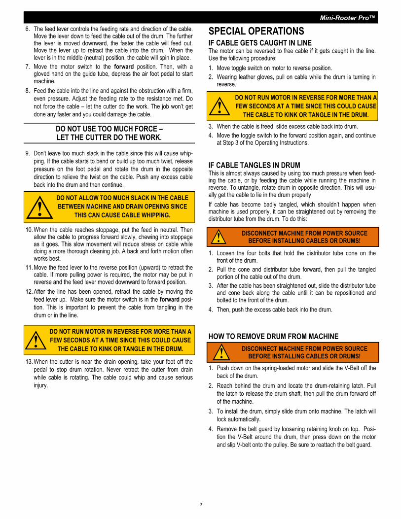
5. Tighten the knob at the top of the Power Cable Feed so that the feed roller presses against the cable. Be sure not to over tighten since this could cause excess cable wear. Note: The Power Cable Feed is designed for use with 3/8” and 1/2” cables only.
Feed Pressure Knob Feed Control Lever
Neutral
Forward
Reverse
Mini-Rooter Pro™
7
SPECIAL OPERATIONS IF CABLE GETS CAUGHT IN LINE The motor can be reversed to free cable if it gets caught in the line. Use the following procedure:
1. Move toggle switch on motor to reverse position.
2. Wearing leather gloves, pull on cable while the drum is turning in reverse.
DISCONNECT MACHINE FROM POWER SOURCE BEFORE INSTALLING CABLES OR DRUMS!
HOW TO REMOVE DRUM FROM MACHINE
1. Push down on the spring-loaded motor and slide the V-Belt off the
back of the drum.
2. Reach behind the drum and locate the drum-retaining latch. Pull
the latch to release the drum shaft, then pull the drum forward off
of the machine.
3. To install the drum, simply slide drum onto machine. The latch will
lock automatically.
4. Remove the belt guard by loosening retaining knob on top. Posi-
tion the V-Belt around the drum, then press down on the motor
and slip V-belt onto the pulley. Be sure to reattach the belt guard.
DISCONNECT MACHINE FROM POWER SOURCE BEFORE INSTALLING CABLES OR DRUMS!
10. When the cable reaches stoppage, put the feed in neutral. Then allow the cable to progress forward slowly, chewing into stoppage as it goes. This slow movement will reduce stress on cable while doing a more thorough cleaning job. A back and forth motion often works best.
11. Move the feed lever to the reverse position (upward) to retract the cable. If more pulling power is required, the motor may be put in reverse and the feed lever moved downward to forward position.
12. After the line has been opened, retract the cable by moving the
feed lever up. Make sure the motor switch is in the forward posi-
tion. This is important to prevent the cable from tangling in the
drum or in the line.
IF CABLE TANGLES IN DRUM This is almost always caused by using too much pressure when feed-ing the cable, or by feeding the cable while running the machine in reverse. To untangle, rotate drum in opposite direction. This will usu-ally get the cable to lie in the drum properly
If cable has become badly tangled, which shouldn’t happen when machine is used properly, it can be straightened out by removing the distributor tube from the drum. To do this:
3. When the cable is freed, slide excess cable back into drum.
4. Move the toggle switch to the forward position again, and continue at Step 3 of the Operating Instructions.
1. Loosen the four bolts that hold the distributor tube cone on the front of the drum.
2. Pull the cone and distributor tube forward, then pull the tangled portion of the cable out of the drum.
3. After the cable has been straightened out, slide the distributor tube and cone back along the cable until it can be repositioned and bolted to the front of the drum.
4. Then, push the excess cable back into the drum.
6. The feed lever controls the feeding rate and direction of the cable. Move the lever down to feed the cable out of the drum. The further the lever is moved downward, the faster the cable will feed out. Move the lever up to retract the cable into the drum. When the lever is in the middle (neutral) position, the cable will spin in place.
7. Move the motor switch to the forward position. Then, with a gloved hand on the guide tube, depress the air foot pedal to start machine.
8. Feed the cable into the line and against the obstruction with a firm,
even pressure. Adjust the feeding rate to the resistance met. Do
not force the cable – let the cutter do the work. The job won’t get
done any faster and you could damage the cable.
9. Don't leave too much slack in the cable since this will cause whip-
ping. If the cable starts to bend or build up too much twist, release
pressure on the foot pedal and rotate the drum in the opposite
direction to relieve the twist on the cable. Push any excess cable
back into the drum and then continue.
DO NOT USE TOO MUCH FORCE – LET THE CUTTER DO THE WORK.
13. When the cutter is near the drain opening, take your foot off the
pedal to stop drum rotation. Never retract the cutter from drain
while cable is rotating. The cable could whip and cause serious
injury.
DO NOT ALLOW TOO MUCH SLACK IN THE CABLE
BETWEEN MACHINE AND DRAIN OPENING SINCE
THIS CAN CAUSE CABLE WHIPPING.
DO NOT RUN MOTOR IN REVERSE FOR MORE THAN A
FEW SECONDS AT A TIME SINCE THIS COULD CAUSE
THE CABLE TO KINK OR TANGLE IN THE DRUM.
DO NOT RUN MOTOR IN REVERSE FOR MORE THAN A
FEW SECONDS AT A TIME SINCE THIS COULD CAUSE
THE CABLE TO KINK OR TANGLE IN THE DRUM.
Mini-Rooter Pro™
8
DISCONNECT MACHINE FROM POWER SOURCE BEFORE INSTALLING CABLES OR DRUMS!
MAINTENANCE
To keep your machine operating smoothly, it is essential that all bear-ings and distributor tube bushings be lubricated. Oiling moving parts is particularly important where machine comes in contact with sand, grit and other abrasive material.
CABLE MAINTENENCE To get maximum service from your cables, be sure that they are clean and well oiled. This not only provides running lubrication but greatly extends the life of the cables as well. Some users periodically pour oil di-rectly into the drum. Then, as the drum turns, the cables get complete lubrication. Our SNAKE OIL is ideally suited for this purpose, since it not only lubricates the cables, it deodorizes them as well.
POWER FEED MAINTENANCE Keep feed free of excessive soil and grit. It is recommended that the feed be flushed with fresh water followed by a light oiling of the mov-ing parts. No disassembly is normally required. Failure to feed can usually be traced to the following possibilities:
DIRT ACCUMULATION Over time, dirt can harden enough to stop roller rotation. Flushing with water followed by liberal oiling can usually restore function. If disas-sembly is required, proceed as follows:
1. Remove the feed pressure knob, springs and spring plunger. Note the positioning of these parts to ease re-assembly. The top roller can now be removed.
2. Remove the snap rings and thrust washers from the bottom hous-ing cylinders. The bottom rollers can now be removed.
3. Re-assembly is done in reverse order.
DISCONNECT MACHINE FROM POWER SOURCE BEFORE PERFORMING MAINTENANCE!
HOW TO USE J-DRUM (Optional. Cat. No. MR-250)
The J-Drum holds 50 feet of 1/4” or 5/16” cable to be used when you need to clear smaller 1-1/4” to 2” lines. These cables have a basin plug head that can be spun through most strainers. (See Cable Application Chart—Table 1)
1. To install cable, open chuck jaws fully so that cable will pass through easily.
2. Slide the back end of the cable (opposite to the end with basin head) through spout and into the drum. The cable will be easier to install if you bend the last inch of cable at a 45 degree angle.
3. When working through difficult stoppages or tight bends, tighten the chuck to provide more torque and to prevent the cable from tangling in the drum.
4. Clean and lubricate chuck regularly to prevent corrosion.
DISCONNECT MACHINE FROM POWER SOURCE BEFORE INSTALLING POWER CABLE FEED!
3. Fully loosen upper clamp knob on the feed support bracket and snap the clamp over the Mini-Rooter’s upper frame. Center the feed over the drum spout and slide the cable through the feed rollers. Then moderately tighten the knob.
4. Loosen the two lower clamp cap screws to allow the clamps to fit over the lower frame. Note that the “short” clamp half should be closest to the floor.
5. It may be necessary to loosen and re-adjust the upper tube length to get the correct fit. Loosen the two set screws in the upper tube and slide the assembly to get the best fit.
6. When alignment is correct, tighten the lower clamp set screws. Screws should not be fully tightened. Make snug only so that the bracket is able to pivot.
7. Fully tighten the upper tube set screws.
8. Test the bracket by loosening the knob and swinging the feed assembly outward. It should disengage and swing smoothly.
9. Swing the feed assembly back and the clamp should snap into the locked position. Tighten the knob to secure the feed for operation. Do not attempt to use or transport the unit unless the upper clamp knob is tightened.
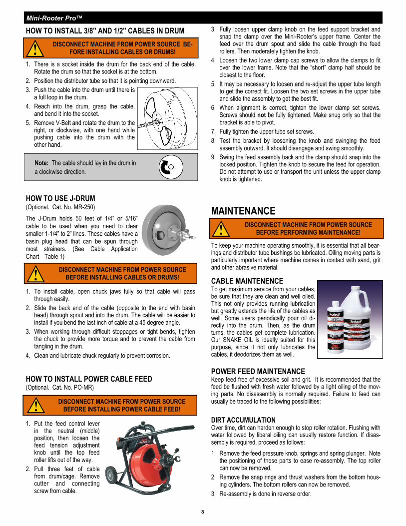
HOW TO INSTALL 3/8" AND 1/2" CABLES IN DRUM
1. There is a socket inside the drum for the back end of the cable. Rotate the drum so that the socket is at the bottom.
2. Position the distributor tube so that it is pointing downward.
3. Push the cable into the drum until there is a full loop in the drum.
4. Reach into the drum, grasp the cable, and bend it into the socket.
5. Remove V-Belt and rotate the drum to the right, or clockwise, with one hand while pushing cable into the drum with the other hand.
DISCONNECT MACHINE FROM POWER SOURCE BE-FORE INSTALLING CABLES OR DRUMS!
Note: The cable should lay in the drum in
a clockwise direction.
HOW TO INSTALL POWER CABLE FEED (Optional. Cat. No. PO-MR)
1. Put the feed control lever in the neutral (middle) position, then loosen the feed tension adjustment knob until the top feed roller lifts out of the way.
2. Pull three feet of cable from drum/cage. Remove cutter and connecting screw from cable.
Mini-Rooter Pro™
9
TROUBLE SHOOTING GUIDE (Table 3)
Problem Probable Cause Solution
Cable kinks or breaks. Operator forcing the cable. Do not force the cable. Let the cutter do the work.
Too much slack between machine
and drain. Allow no more than two feet between machine and drain.
Cable used in wrong size drain line. A cable that is too large or too small in diameter for a line is more likely
to kink. (Consult Table 1—Cable Applications.)
Cable exposed to acid. Clean and oil cables regularly.
Cable tangles in drum/cage. Operator forcing the cable. Do not force the cable. Let the cutter do the work.
Machine running in reverse. Do not run the machine in reverse to retract the cable from the drain.
Distributor tube frozen. Lubricate distributor tube bushings.
Drum/cage stops while foot
pedal depressed. Hole in pedal or hose. Replace as required.
Hole in diaphragm switch. If no hole found in pedal or hose, replace diaphragm switch.
Drum/cage turns in one direc-
tion but not other.
Reverse switch or momentary con-
tact switch failure.
Replace switch. Note: Momentary contact switch must be held in
place when using reverse.
Ground fault circuit interrupter
trips and will not reset.
Damaged power cord or extension
cord. Replace cords.
Short circuit in motor. Take motor to authorized repair center.
Faulty ground fault circuit interrupter. Replace ground fault circuit interrupter.
Motor turns but drum/cage
does not.
Safety Slip Clutch (optional)
engaged. Do not force cable.
Failure to feed. Cable tangled in drum. Do not run machine in reverse. Use proper cable size. (Consult Cable
Application Chart—Table 1).
Feed misadjusted. If feed pressure knob is too loose the cable will slip. If it is too tight the
feed rollers will wear prematurely.
Feed roller frozen. Clean and lubricate feed rollers regularly. Replace worn rollers.
Worn cable. When cable coils wear flat, cable should be replaced.
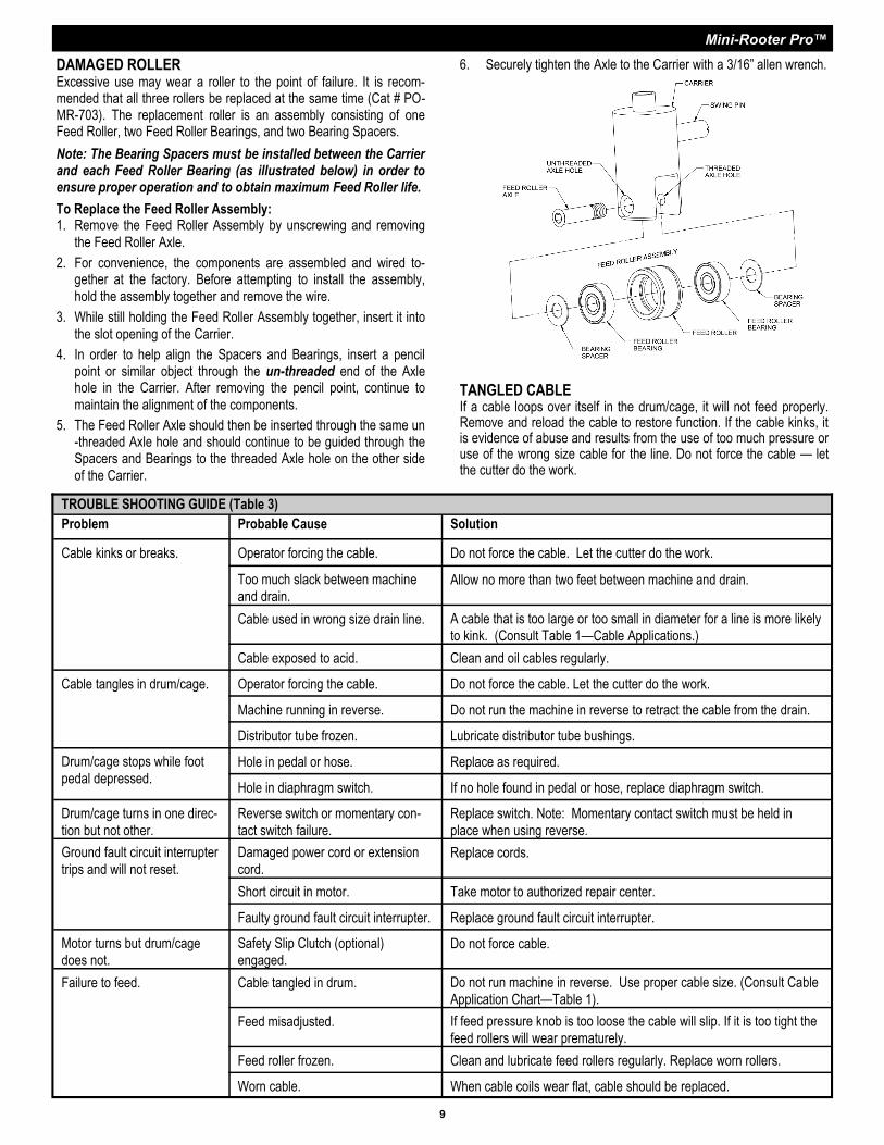
DAMAGED ROLLER Excessive use may wear a roller to the point of failure. It is recom-mended that all three rollers be replaced at the same time (Cat # PO-MR-703). The replacement roller is an assembly consisting of one Feed Roller, two Feed Roller Bearings, and two Bearing Spacers.
Note: The Bearing Spacers must be installed between the Carrier and each Feed Roller Bearing (as illustrated below) in order to ensure proper operation and to obtain maximum Feed Roller life.
To Replace the Feed Roller Assembly: 1. Remove the Feed Roller Assembly by unscrewing and removing
the Feed Roller Axle.
2. For convenience, the components are assembled and wired to-gether at the factory. Before attempting to install the assembly,
hold the assembly together and remove the wire.
3. While still holding the Feed Roller Assembly together, insert it into
the slot opening of the Carrier.
4. In order to help align the Spacers and Bearings, insert a pencil point or similar object through the un-threaded end of the Axle hole in the Carrier. After removing the pencil point, continue to
maintain the alignment of the components.
5. The Feed Roller Axle should then be inserted through the same un-threaded Axle hole and should continue to be guided through the Spacers and Bearings to the threaded Axle hole on the other side
of the Carrier.
TANGLED CABLE If a cable loops over itself in the drum/cage, it will not feed properly. Remove and reload the cable to restore function. If the cable kinks, it is evidence of abuse and results from the use of too much pressure or use of the wrong size cable for the line. Do not force the cable — let the cutter do the work.
6. Securely tighten the Axle to the Carrier with a 3/16” allen wrench.

Mini-Rooter Pro™
10
MINI-ROOTER PRO PARTS LIST
CAT. NO. DESCRIPTION CAT. NO. DESCRIPTION
MR-100-2 Complete Frame Assembly MR-210 Drum Connecting Cable
MR-101-2 Frame Only MR-210-A Connecting Cable Bolt, Nut, & Washer
MR-102-2 Rubber Leg Tip (2) MR-216 Drum Retaining Bolt
MR-104 Shaft Retaining Pin MR-217 Drum Retaining Washer
MR-104-A Retaining Pin Spring MR-218 Felt Washer
MR-104-B Retaining Pin Collar MR-250 "J" Drum (for 1/4" & 5/16" Cables)
MR-105 Shaft Spacer MR-251-1 Rear Shell
MR-106 Knob for Handle MR-252 Round Head Machine Screw & Nut (2)
MR-107 Handle w/Grip MR-255-1 Front Drum Assembly for Collet Chuck
MR-107-A Rubber Grip MR-255-A-1 Spout Assembly for Collet Chuck
MR-108 Bolt w/Lock Washer MR-255-B Bushing
MR-108-A Lock Washer MR-257 Shaft for "J" Drum
MR-110 6” Wheel (2) MR-260-1 Collet Chuck Assembly
MR-111 Retaining Cap (2) MR-300 Motor 1/3 hp w/GFCI, Foot Switch & Rev. Switch
MR-112 Washers (4) GFI-10 10' Cord w/GFCI
MR-115 Axle MR-301-B Knob for Mounting Stud
MR-200 Complete Drum Assembly (Enclosed) MR-301-C Washer Under Beld Guard Knob
MR-200-2 Drum w/Inner Drum Cage MR-301-D Stud Replacement
MR-201-2 Drum Shell MR-303 V-Belt Pulley
MR-201-A-2 Rear Hub Assembly w/Bushing MR-304-1 Motor Support w/Bolts, Nuts, & Washers
MR-201-A-3 Rear Hub Assembly for Inner Drum MR-304-A Guide Screws (2)
MR-201-C Screws, Nuts & Lockwashers (5) MR-304-C Nuts, Bolts, & Washers (4)
MR-201-D Rear Hub Busing MR-305 Motor Support Spring
MR-201-E Retaining Screw MR-306 V-Belt (45")
MR-201/202-2 Complete Shaft & Hub Assembly MR-307-2 Belt Guard w/Slot for Mounting Stud
MR-202 Shaft MR-308 Foot Switch & Reverse Switch Assembly
MR-202-A Retaining Ring (2) MR-308-A Box Only w/Cover & Screws
MR-202-B Steel Washer MR-308-B Foot Pedal & Hose
MR-202-C Felt Washer MR-308-C Hose Clamp (2)
MR-203-B Edging (2) MR-308-D Foot Pedal Only
MR-204 Distributor Tube MR-308-E Power Switch Diaphragm
MR-204-A Distributor Tube Rear Collar w/Set Screw MR-308-F Air Hose
MR-204-B Distributor Tube Front Collar w/Set Screw MR-308-G Reverse Switch (3-Way)
MR-204-2 Inner Drum Cage w/Spring Distributor Tube MR-308-J Barbed Adapter
MR-204-4 Distributor Tube Spring w/Bushing MR-308-K Switch Guard
MR-205 Fiber Washer (2) MR-308-N Strain Relief Nut
MR-206 Front Hub Set of Safety Decals MR-DECAL
MR-206-R Front Hub (Silver) MR-DVD Instructional DVD
MR-206-A Front Hub Bushing PO-MR Mini-Rooter Power Cable Feed
MR-207 Round Head Cap Screw (4) MR-GT Guide Tube
MR-209 Inner Drum Cage

Mini-Rooter Pro™
11

Mini-Rooter Pro™
General Wire Spring Co, 1101 Thompson Avenue McKees Rocks, PA 15136
412-771-6300 www.drainbrain.com
© General Wire Spring Co. 2012 C-MRPOI-0612