Millimeter-Wave Antenna of a Travelling-Wave Long Sinusoidal Slot in the Narrow Face of a...
9
Int. J. Electron. Commun. (AEÜ) 66 (2012) 659–667 Contents lists available at SciVerse ScienceDirect International Journal of Electronics and Communications (AEÜ) jou rn al h omepage: www.elsevier.de/aeue Millimeter-wave antenna of a travelling-wave long sinusoidal slot in the broad face of a rectangular waveguide A. Oral Salman ∗ TUBITAK BILGEM, Information Technologies Institute, Sensor Systems Group, P.O. Box 74, 41470 Gebze, Kocaeli, Turkey a r t i c l e i n f o Article history: Received 1 March 2011 Accepted 7 December 2011 Keywords: Millimeter-waves Slotted-waveguide antenna Leaky waves Travelling-wave antenna Cross-polarization suppression Grid polarizer/filter a b s t r a c t A travelling-wave long sinusoidal slot in the broad face of a millimeter-wave (Ka-Band) rectangular waveguide is investigated. Similarities and differences with a same-shaped slot, but in the narrow face of the waveguide, which was investigated in a former study [1], are also discussed. It is observed that the most important difference between two antenna structures is the applied analytical model. It is found in measurements that the antenna with a broad face can only be described by an electric current model unlike the antenna with a narrow face where the magnetic current model agrees with measurements. In experimental study, some antenna parameters of the structure are demonstrated. The sinusoidal slot antenna investigated in this study has also a cross-polarized beam like the one in the narrow face of rectangular waveguide and a similar metallic grid polarizer is used like in the previous study to suppress this cross polarized beam. A suppression level up to 12 dB is reached. Antenna efficiency is calculated using S-parameters measurement and a remarkable increment is obtained after the polarizer is applied. © 2011 Elsevier GmbH. All rights reserved. 1. Introduction Slotted waveguide antennas (SWA) are well-known and efficient radiators [2–4]. They are widely used in radar and telecom- munication applications. They have simple structure, light weight and low level side lobes. Their efficiency is also high. The disadvan- tage of the SWAs is their low bandwidth due to their waveguide type excitation. Some theoretical studies were given in the litera- ture for analyzing the slotted-waveguide antennas [5–7]. The slot’s length is a crucial parameter for SWAs. A long slot, which is applied in this study, is a travelling-wave struc- ture [8], which has a length more than three wavelengths and it is terminated properly. Radiated fields of a slot can be calcu- lated by introducing a magnetic current along slot [2,3]. Generally, rectangular-profiled waveguides are used in creating SWAs and either broad or narrow face of waveguide can be preferred for slot- ting. This kind of an antenna is considered as a leaky wave structure and electromagnetic power continuously leaks out of the waveg- uide. The shape of a long slot in waveguide is also critical and it deter- mines the properties of radiated fields from the slot. In this study, the sinusoidal shape is chosen. The aim of choosing this shape is its novelty of application in slotted-waveguide antennas. Sinu- soidal shape was also applied to the other kinds of travelling-wave ∗ Tel.: +90 262 675 31 98; fax: +90 262 646 31 87. E-mail address: [email protected] antennas as well; wire antennas [9–12], strip-microstrip antennas [13–15], and dielectric leaky-wave antennas [16,17]. The radiation properties of a travelling-wave long sinusoidal slot in the narrow face of millimeter-wave (Ka-Band) rectangular waveguide were investigated in [1] and it was demonstrated that the radiation of this antenna could be analyzed by applying the magnetic current model. In this study, a same-shaped travelling- wave long slot but in the broad face of a rectangular waveguide at the same frequency band is investigated and it will be shown that this structure can only be analyzed by the electric current model. Other similarities and the differences between two antenna types will also be discussed. An analytical model for calculating radiated fields of the sinu- soidal slot in the broad face of waveguide is given in the second section of the paper. In the third section, far-field pattern mea- surements are given and measured patterns are compared with analytical ones. Some parameters of the structure such as beam angle, HPBW and velocity ratio variations with frequency are also demonstrated in the same section. Suppression of cross polarized beam of the antenna with a grid polarizer will be discussed in the third section. S-parameters measurement and antenna efficiencies with and without grid polarizer can also be found in the same section. 2. The analytical approach Although the radiation problem of a slot can be solved by apply- ing the magnetic current model [1–3], it will be shown in Section 1434-8411/$ – see front matter © 2011 Elsevier GmbH. All rights reserved. doi:10.1016/j.aeue.2011.12.004
-
Upload
independent -
Category
Documents
-
view
0 -
download
0
Transcript of Millimeter-Wave Antenna of a Travelling-Wave Long Sinusoidal Slot in the Narrow Face of a...
Mf
AT
a
ARA
KMSLTCG
1
emattt
stilretau
mtis
1d
Int. J. Electron. Commun. (AEÜ) 66 (2012) 659– 667
Contents lists available at SciVerse ScienceDirect
International Journal of Electronics andCommunications (AEÜ)
jou rn al h omepage: www.elsev ier .de /aeue
illimeter-wave antenna of a travelling-wave long sinusoidal slot in the broadace of a rectangular waveguide
. Oral Salman ∗
UBITAK BILGEM, Information Technologies Institute, Sensor Systems Group, P.O. Box 74, 41470 Gebze, Kocaeli, Turkey
r t i c l e i n f o
rticle history:eceived 1 March 2011ccepted 7 December 2011
eywords:illimeter-waves
a b s t r a c t
A travelling-wave long sinusoidal slot in the broad face of a millimeter-wave (Ka-Band) rectangularwaveguide is investigated. Similarities and differences with a same-shaped slot, but in the narrow face ofthe waveguide, which was investigated in a former study [1], are also discussed. It is observed that themost important difference between two antenna structures is the applied analytical model. It is foundin measurements that the antenna with a broad face can only be described by an electric current model
lotted-waveguide antennaeaky wavesravelling-wave antennaross-polarization suppressionrid polarizer/filter
unlike the antenna with a narrow face where the magnetic current model agrees with measurements.In experimental study, some antenna parameters of the structure are demonstrated. The sinusoidal slotantenna investigated in this study has also a cross-polarized beam like the one in the narrow face ofrectangular waveguide and a similar metallic grid polarizer is used like in the previous study to suppressthis cross polarized beam. A suppression level up to 12 dB is reached. Antenna efficiency is calculatedusing S-parameters measurement and a remarkable increment is obtained after the polarizer is applied.
. Introduction
Slotted waveguide antennas (SWA) are well-known andfficient radiators [2–4]. They are widely used in radar and telecom-unication applications. They have simple structure, light weight
nd low level side lobes. Their efficiency is also high. The disadvan-age of the SWAs is their low bandwidth due to their waveguideype excitation. Some theoretical studies were given in the litera-ure for analyzing the slotted-waveguide antennas [5–7].
The slot’s length is a crucial parameter for SWAs. A longlot, which is applied in this study, is a travelling-wave struc-ure [8], which has a length more than three wavelengths andt is terminated properly. Radiated fields of a slot can be calcu-ated by introducing a magnetic current along slot [2,3]. Generally,ectangular-profiled waveguides are used in creating SWAs andither broad or narrow face of waveguide can be preferred for slot-ing. This kind of an antenna is considered as a leaky wave structurend electromagnetic power continuously leaks out of the waveg-ide.
The shape of a long slot in waveguide is also critical and it deter-ines the properties of radiated fields from the slot. In this study,
he sinusoidal shape is chosen. The aim of choosing this shapes its novelty of application in slotted-waveguide antennas. Sinu-oidal shape was also applied to the other kinds of travelling-wave
∗ Tel.: +90 262 675 31 98; fax: +90 262 646 31 87.E-mail address: [email protected]
434-8411/$ – see front matter © 2011 Elsevier GmbH. All rights reserved.oi:10.1016/j.aeue.2011.12.004
© 2011 Elsevier GmbH. All rights reserved.
antennas as well; wire antennas [9–12], strip-microstrip antennas[13–15], and dielectric leaky-wave antennas [16,17].
The radiation properties of a travelling-wave long sinusoidalslot in the narrow face of millimeter-wave (Ka-Band) rectangularwaveguide were investigated in [1] and it was demonstrated thatthe radiation of this antenna could be analyzed by applying themagnetic current model. In this study, a same-shaped travelling-wave long slot but in the broad face of a rectangular waveguide atthe same frequency band is investigated and it will be shown thatthis structure can only be analyzed by the electric current model.Other similarities and the differences between two antenna typeswill also be discussed.
An analytical model for calculating radiated fields of the sinu-soidal slot in the broad face of waveguide is given in the secondsection of the paper. In the third section, far-field pattern mea-surements are given and measured patterns are compared withanalytical ones. Some parameters of the structure such as beamangle, HPBW and velocity ratio variations with frequency are alsodemonstrated in the same section. Suppression of cross polarizedbeam of the antenna with a grid polarizer will be discussed in thethird section. S-parameters measurement and antenna efficiencieswith and without grid polarizer can also be found in the samesection.
2. The analytical approach
Although the radiation problem of a slot can be solved by apply-ing the magnetic current model [1–3], it will be shown in Section
660 A.O. Salman / Int. J. Electron. Commun. (AEÜ) 66 (2012) 659– 667
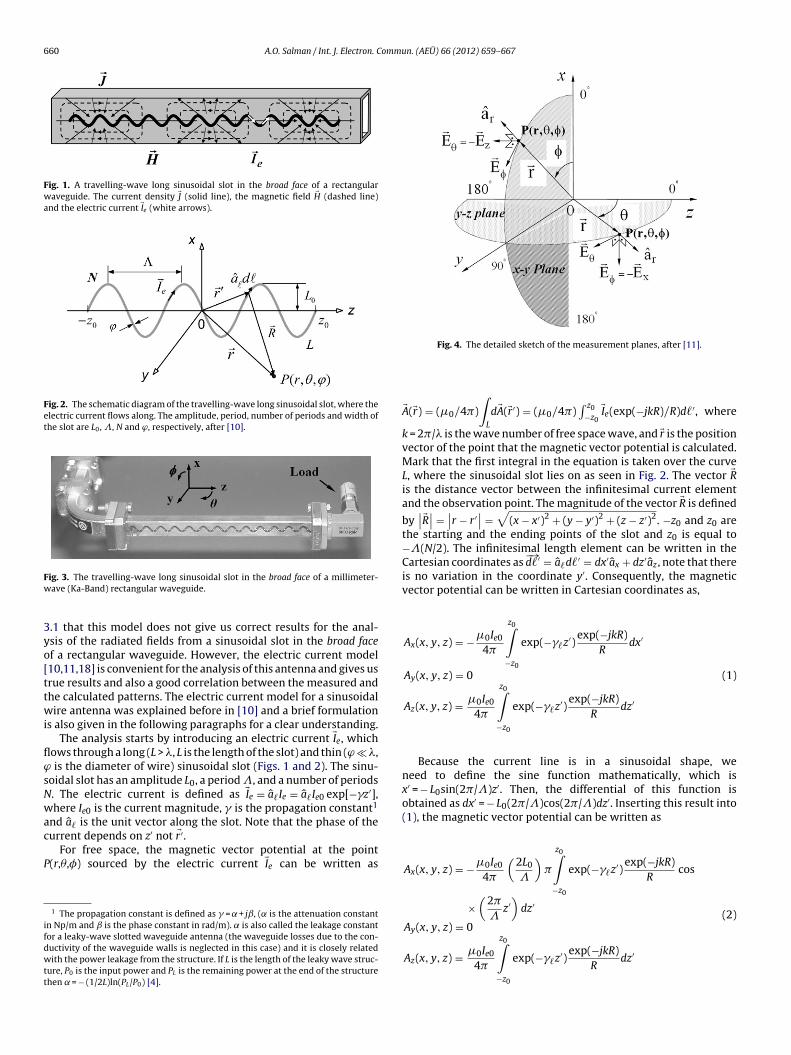
Fig. 1. A travelling-wave long sinusoidal slot in the broad face of a rectangularwaveguide. The current density �J (solid line), the magnetic field �H (dashed line)and the electric current �Ie (white arrows).
Fig. 2. The schematic diagram of the travelling-wave long sinusoidal slot, where theelectric current flows along. The amplitude, period, number of periods and width ofthe slot are L0, �, N and ϕ, respectively, after [10].
Fw
3yo[ttwi
flϕsNwac
P
ifdwtt
ig. 3. The travelling-wave long sinusoidal slot in the broad face of a millimeter-ave (Ka-Band) rectangular waveguide.
.1 that this model does not give us correct results for the anal-sis of the radiated fields from a sinusoidal slot in the broad facef a rectangular waveguide. However, the electric current model10,11,18] is convenient for the analysis of this antenna and gives usrue results and also a good correlation between the measured andhe calculated patterns. The electric current model for a sinusoidalire antenna was explained before in [10] and a brief formulation
s also given in the following paragraphs for a clear understanding.The analysis starts by introducing an electric current �Ie, which
ows through a long (L > �, L is the length of the slot) and thin (ϕ � �, is the diameter of wire) sinusoidal slot (Figs. 1 and 2). The sinu-oidal slot has an amplitude L0, a period �, and a number of periods. The electric current is defined as �Ie = a�Ie = a�Ie0 exp[−�z′],here Ie0 is the current magnitude, � is the propagation constant1
nd a� is the unit vector along the slot. Note that the phase of theurrent depends on z′ not �r′.
For free space, the magnetic vector potential at the point(r,�,�) sourced by the electric current �Ie can be written as
1 The propagation constant is defined as � = + jˇ, ( is the attenuation constantn Np/m and is the phase constant in rad/m). is also called the leakage constantor a leaky-wave slotted waveguide antenna (the waveguide losses due to the con-uctivity of the waveguide walls is neglected in this case) and it is closely relatedith the power leakage from the structure. If L is the length of the leaky wave struc-
ure, P0 is the input power and PL is the remaining power at the end of the structurehen = − (1/2L)ln(PL/P0) [4].
Fig. 4. The detailed sketch of the measurement planes, after [11].
�A(�r) = (0/4)
∫L
d�A(�r′) = (0/4)∫ z0
−z0�Ie(exp(−jkR)/R)d�′, where
k = 2/� is the wave number of free space wave, and �r is the positionvector of the point that the magnetic vector potential is calculated.Mark that the first integral in the equation is taken over the curveL, where the sinusoidal slot lies on as seen in Fig. 2. The vector �Ris the distance vector between the infinitesimal current elementand the observation point. The magnitude of the vector �R is defined
by∣∣�R∣∣ =
∣∣r − r′∣∣ =√
(x − x′)2 + (y − y′)2 + (z − z′)2. −z0 and z0 arethe starting and the ending points of the slot and z0 is equal to−�(N/2). The infinitesimal length element can be written in theCartesian coordinates as
−→d�′ = a�d�′ = dx′ax + dz′az , note that there
is no variation in the coordinate y′. Consequently, the magneticvector potential can be written in Cartesian coordinates as,
Ax(x, y, z) = −0Ie0
4
z0∫−z0
exp(−��z′)exp(−jkR)
Rdx′
Ay(x, y, z) = 0
Az(x, y, z) = 0Ie0
4
z0∫−z0
exp(−��z′)exp(−jkR)
Rdz′
(1)
Because the current line is in a sinusoidal shape, weneed to define the sine function mathematically, which isx′ = − L0sin(2/�)z′. Then, the differential of this function isobtained as dx′ = − L0(2/�)cos(2/�)dz′. Inserting this result into(1), the magnetic vector potential can be written as
Ax(x, y, z) = −0Ie0
4
(2L0
�
)
z0∫−z0
exp(−��z′)exp(−jkR)
Rcos
×(
2
�z′)
dz′
Ay(x, y, z) = 0
Az(x, y, z) = 0Ie0
z0∫exp(−� z′)
exp(−jkR)dz′
(2)
4−z0
� R
A.O. Salman / Int. J. Electron. Commun. (AEÜ) 66 (2012) 659– 667 661
b a
0 30 60 90 120 150 180-80
-70
-60
-50
-40
-30
-20
29 GHz
Rec
eive
d P
ower
(dB
)
(degree)0 30 60 90 120 150 180
-80
-70
-60
-50
-40
-30
-20
29 GHz
Rec
eive
d P
ower
(dB
)
(degree)
0 30 60 90 120 150 180-80
-70
-60
-50
-40
-30
-20
(degree)
31 GHz
Rec
eive
d P
ower
(dB
)
0 30 60 90 120 150 180-80
-70
-60
-50
-40
-30
-20
Rec
eive
d P
ower
(dB
) (degree)
31 GHz
0 30 60 90 120 150 180-80
-70
-60
-50
-40
-30
-20
33 GHz
Rec
eive
d P
ower
(dB
)
0 30 60 90 120 150 180-80
-70
-60
-50
-40
-30
-20
Rec
eive
d P
ower
(dB
)
(degree)
33 GHz
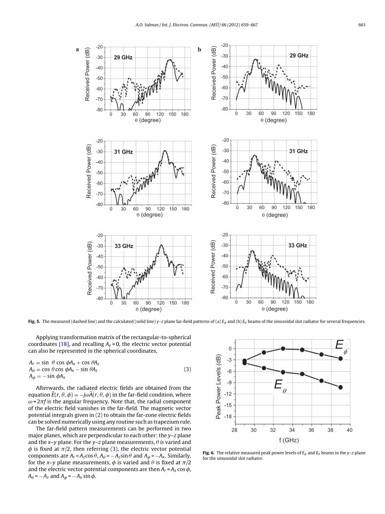
F patterns of (a) E� and (b) E� beams of the sinusoidal slot radiator for several frequencies.
cc
eωopc
ma�cfaA
28 30 32 34 36 38 40
-18
-15
-12
-9
-6
-3
0
E
E
f (GHz)
Pea
k P
ower
Lev
els
(dB)
Fig. 6. The relative measured peak power levels of E� and E� beams in the y–z plane
(degree)
ig. 5. The measured (dashed line) and the calculated (solid line) y–z plane far-field
Applying transformation matrix of the rectangular-to-sphericaloordinates [18], and recalling Ay = 0, the electric vector potentialan also be represented in the spherical coordinates,
Ar = sin � cos �Ax + cos �Az
A� = cos � cos �Ax − sin �Az
A� = − sin �Ax
(3)
Afterwards, the radiated electric fields are obtained from thequation �E(r, �, �) = −jω�A(r, �, �) in the far-field condition, where
= 2f is the angular frequency. Note that, the radial componentf the electric field vanishes in the far-field. The magnetic vectorotential integrals given in (2) to obtain the far-zone electric fieldsan be solved numerically using any routine such as trapezium rule.
The far-field pattern measurements can be performed in twoajor planes, which are perpendicular to each other: the y–z plane
nd the x–y plane. For the y–z plane measurements, � is varied and is fixed at /2, then referring (3), the electric vector potential
omponents are Ar = Azcos �, A� = − Azsin � and A� = −Ax. Similarly,or the x–y plane measurements, � is varied and � is fixed at /2nd the electric vector potential components are then Ar = Ax cos �,� = − Az and A� = − Ax sin �.
for the sinusoidal slot radiator.

662 A.O. Salman / Int. J. Electron. Commun. (AEÜ) 66 (2012) 659– 667
a b
28 30 32 34 36 38 4020
40
60
80
100
120
140
160
E
E
Bea
m A
ngle
(deg
ree)
28 30 32 34 36 38 406
8
10
12
14
16
HP
BW
(deg
ree) E
E
am w
3
3sw
iuw8naamspoFt
sebtams
aqbctaEAtlbtwl
a
w
to the patterns of the y–z plane (Fig. 5) and x–y plane (Fig. 8), theradiated beam is fan-shaped.
f(GHz)
Fig. 7. The measured (a) beam pointing angles and (b) half power be
. Measurements
.1. Radiation properties of the travelling-wave long sinusoidallot in the broad face of millimeter-wave (Ka-Band) rectangularaveguide
Before measurements, a long slot in sinusoidal shape was milledn the broad face of a standard Ka-Band rectangular waveguidesing a CNC milling-machine. The slot is thin and long, where itsidth and longitudinal length are 1 mm (=�/10 at 30 GHz) and
4 mm (∼=8� at 30 GHz), respectively. The period, amplitude and theumber of periods of the sinusoidal slot are � = 7 mm, L0 = 1.5 mmnd N = 12, respectively.2 These dimensions were chosen to obtain
radiated beam which has a moderate beam width and a maxi-um field strength (refer [1] for a discussion on effects of sinusoidal
lot’s geometrical dimensions on the radiated field patterns). Thehoto of the travelling-wave long sinusoidal slot in the broad facef a millimeter-wave (Ka-Band) rectangular waveguide is given inig. 3. The antenna is terminated with a 50 �-load via a waveguide-o-coax transition.
Far-field patterns of the sinusoidal slot radiator were mea-ured at Ka-Band (26.5–40 GHz), which is located in the lowerdge of the millimeter-wave region, by a measurement systemased on the Agilent N5230A vector network analyzer. The pat-ern measurements3 were performed in two major planes, whichre perpendicular to each other: the y–z plane and the x–y plane asentioned in the previous section. A detailed sketch of the mea-
urement planes is shown in Fig. 4.The measured and calculated y–z plane far-field patterns of E�
nd E� components of the sinusoidal slot radiator for several fre-uencies are shown in Fig. 5. The calculated patterns were obtainedy solving the integrals given in (2) numerically with a MATLABode based on the analytical electric current approach explained inhe previous section. There is a good match between the measurednd the calculated patterns except the minor lobe in the measured
� beams (Fig. 5(b)), which is inconsistent with the analytical ones. frequency-scanning behavior for the radiator is observed from
he patterns. One can also see from the graphs that the side-lobeevels of the radiator is approximately −10 dB and can be reducedy choosing the aperture length longer in the expense of decreasinghe beam width. To reduce possible reflections from the flanges, theaveguide can be extended with a non-slotted part or an absorber
ayer can be inserted on the face of each flange.There is an agreement between the measured and the calculated
ntenna patterns in Fig. 5. One may compare these patterns with
2 The dimensions are the same with the sinusoidal slot in the narrow face ofaveguide [1].3 Refer [1] for more detail for the pattern measurements.
f (GHz)
idths (HPBW) versus frequency of E� and E� beams in the y–z plane.
the ones of the sinusoidal slot in the narrow face of the rectangularwaveguide, which was analyzed with the magnetic current model[1] and see the difference, especially the places of the major lobesthat E� beam is interchanged with the E� beams. This result showsthat the electric current model is true choice for the analysis of theinvestigated antenna.
The relative measured peak power levels of E� and E� beams arealso shown in Fig. 6. The E� beam has larger beam strength than E�
beam has.The beam pointing angles and the half power beam widths
(HPBW) versus frequency for the both field components (E� andE� beams) measured in the y–z plane are given in Fig. 7(a) and (b),respectively. It is observed from Fig. 7(a) that the beam pointingangle decreases with the increasing frequency for the both fieldcomponents and none of the beams (E� and E�) reaches the broad-side angle in the operating frequency range. It is also observed fromFig. 7(a) that the beam pointing angle differences ( �) of E� andE� beams are 41◦ and 19◦, respectively, in 10 GHz frequency range( f) for the both components. So, the scanning rates ( �/ f) of E�
and E� beams are 4.1◦/GHz and 1.9◦/GHz, respectively. Thus, thescanning rate of E� beam is higher than the scanning rate of E�
beam.4
One can observe from Fig. 7(b) that the average half power beamwidths (HPBWs) of E� and E� beams in the y–z plane are 8◦ and 13◦,respectively5. Thus, E� beam is narrower than E� beam.
It is observed from the beam pointing angles and HPBWs given inFig. 7 that E� and E� beams are interchanged when they are com-pared to the ones of the sinusoidal slot in the narrow face of therectangular waveguide [1]. This result also shows that the analysishas to be done as if an electric current flows along the investigatedantenna, which is the sinusoidal slot in the broad face of waveguideinstead of a magnetic current.
The far-field patterns of the sinusoidal slot radiator in x–y plane(at � = /2), which is perpendicular to the y–z plane, were also mea-sured. The measured patterns are compared with the calculatedones as well. In Fig. 8, the measured (dashed lines) and calculated(solid lines) x–y plane normalized far-field patterns for the fieldcomponents of E� at 27 GHz and E� at 35 GHz are given. According
4 The beam scanning rates of E� and E� beams for the sinusoidal slot in the narrowface of waveguide [1] were found as 1.93◦/GHz and 4.83◦/GHz, respectively. Note thatthe values are similar when E� and E� beams are interchanged for the sinusoidal slotin the broad face.
5 The average HPBWs of E� and E� beams for the sinusoidal slot in the narrowface of waveguide [1] were 10◦ and 7◦ , respectively. Note that the values are similarwhen E� and E� beams are interchanged for the sinusoidal slot in the broad face.

A.O. Salman / Int. J. Electron. Commun. (AEÜ) 66 (2012) 659– 667 663
0 30 60 90 120 150 180-12
-10
-8
-6
-4
-2
0
2a b
(degree)
Rec
eive
d P
ower
(dB
)
0 30 60 90 120 150 180
-20
-15
-10
-5
0
Rec
eive
d P
ower
(dB
)
(degree)
Fig. 8. The measured (dashed lines) and calculated (solid lines) x–y plane (where � = /2) normalized far-field patterns of the sinusoidal slot radiator for the field componentsof (a) E� at 27 GHz and (b) E� at 35 GHz.
28 30 32 34 36 38 401.1
1.2
1.3
1.4
1.5
1.6
broad face
narrow face
Vel
ocity
Rat
io (v
p/c)
f (GHz)
Ftf
ofmhb
ivrftti[tettdwi
s
ao
ig. 9. The variation of velocity ratios vp/c versus frequency for the sinusoidal slot inhe broad face (-�-) and narrow face (-©-) of the rectangular waveguide. The curveor the narrow face is after [1].
It is also observed that the shapes of the patterns in Fig. 8btained for the sinusoidal slot are identical with the ones obtainedor the same-shaped wire antenna [10], where the electric current
odel is used. This is also evidence that the electric current modelas to be used for the analysis of the sinusoidal slot antenna in theroad face of waveguide.
The velocity ratio [1,10,11,16,17] for a travelling wave structures another parameter, which is defined as the ratio of the phaseelocity of wave to the speed of light. The variation of velocityatios6 vp/c versus frequency for the sinusoidal slot in the broadace of waveguide is given in Fig. 9. The velocity ratio is also equalo k/ˇ, which is the ratio of the wave number of free space wave tohe phase constant of the wave along the sinusoidal slot. The veloc-ty ratio curve of the sinusoidal slot in the narrow face of waveguide1] is also appended for comparison. It is observed from the figurehat the structure is a fast-wave structure (vp/c) > 1, which is anxpected result for a waveguide structure, and vp/c decreases withhe increasing frequency. It is also observed that the wave alonghe sinusoidal slot in the broad face of waveguide is faster at someegree than the one along the sinusoidal slot in the narrow face ofaveguide and the difference in phase velocities increases with the
ncreasing frequency.It is noted from the far-field patterns (Fig. 5) that the sinusoidal
lot radiator in the broad face of waveguide has two beams (E� and
6 The velocity ratios were obtained by matching the measured patterns with thenalytical ones, which are calculated using the theory given in the second sectionf the paper.
Fig. 10. (a) The grid polarizer (the dimensions are given in mm) and (b) the sinu-soidal slot antenna in the broad face of waveguide after mounting the grid polarizer.
E� beams). They can be called co and cross-polarized beams, whichscan in two different angle regions.7 This behavior of the radia-tor is not convenient for antenna applications. In the next section,it will be shown how to filter/suppress the cross polarization ofthe radiator to obtain an efficient single-beam antenna from thisradiator.
3.2. Filtering/suppressing the cross-polarized beam of thesinusoidal slot radiator
A grid polarizer can be used to suppress the cross-polarizedbeam of a slotted waveguide antenna [4,19]. The same techniquewas applied to suppress the cross-polarized beam of a sinusoidalslot in narrow face of waveguide [1]. A similar grid polarizer isdesigned for the investigated antenna (the sinusoidal slot in thebroad face of wave guide), and it is fabricated using a water-jetmachine.
The structure of the grid polarizer can be seen in Fig. 10(a) and itconsists of 24 cavities. The width of each grid is 1 mm and the gridsare located on the maxima and minima of the sinusoidal slot, givinga distance between two adjacent grids equals to the half period ofthe sinusoidal slot. The operating principle of the grid polarizer isfollowing. The E� beam, which is parallel to the grids, looses a large
portion of its power on the grids by transferring its energy to thefree electrons into the metallic grids of the polarizer and the radi-ated field strength of this polarization rapidly decreases. The photo7 The same case was also observed for the sinusoidal slot in narrow face of waveg-uide [1].
664 A.O. Salman / Int. J. Electron. Commun. (AEÜ) 66 (2012) 659– 667
a b
0 30 60 90 120 150 180-80
-70
-60
-50
-40
-30
-2029 GHz
(degree)
Rec
eive
d P
ower
(dB
)
0 30 60 90 120 150 180-80
-70
-60
-50
-40
-30
-20
Rec
eive
d Po
wer
(dB)
(degree)
29 GHz
0 30 60 90 120 150 180-80
-70
-60
-50
-40
-30
-2031 GHz
(degree)
Rec
eive
d P
ower
(dB
)
0 30 60 90 120 150 180-80
-70
-60
-50
-40
-30
-2031 GHz
(degree)
Rec
eive
d P
ower
(dB
)
0 30 60 90 120 150 180-80
-70
-60
-50
-40
-30
-2033 GHz
(degree)
Rec
eive
d P
ower
(dB
)
0 30 60 90 120 150 180-80
-70
-60
-50
-40
-30
-2033 GHz
(degree)
Rec
eive
d P
ower
(dB
)
F ld patterns of (a) the cross-polarized field component (E�) and (b) the co-polarized fieldc guide with the grid polarizer for three frequencies.
os
pppott
Hap
ta
-15
-12
-9
-6
-3
0
E
E
Pow
er L
evel
s (d
B)
ig. 11. The measured (dashed line) and the simulated (solid line) y-z plane far-fieomponent (E�) of the sinusoidal slot radiator in the broad face of rectangular wave
f the antenna after mounting the grid polarizer to the sinusoidallot in the broad face of waveguide is also given in Fig. 10b.8
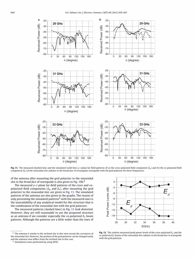
The measured y–z plane far-field patterns of the cross and co-olarized field components (E� and E�), after mounting the gridolarizer to the sinusoidal slot, are given in Fig. 11. The simulatedatterns of the antenna are also given in the graphs. The reason ofnly presenting the simulated patterns9 with the measured ones ishe unavailability of any analytical model for this structure that ishe combination of the sinusoidal slot with the grid polarizer.
The measured patterns (dashed lines) in Fig. 11 look distorted.
owever, they are still reasonable to use the proposed structures an antenna if we consider especially the co-polarized E� beamatterns. Although the patterns are a little wider than the ones of8 The antenna is similar to the inclined slot in this view except the curvatures ofhe sinusoidal slot. However, the position of the grid polarizer can be changed easilynd the antenna view differs from the inclined slot in this case.9 Simulations were performed by using HFSS.
28 30 32 34 36 38 40
-18Pea
k
f(GHz)
Fig. 12. The relative measured peak power levels of the cross-polarized E� and theco-polarized E� beams of the sinusoidal slot radiator in the broad face in waveguidewith the grid polarizer.
A.O. Salman / Int. J. Electron. Commun. (AEÜ) 66 (2012) 659– 667 665
28 30 32 34 36 38 40-3
0
3
6
9
12
15
18
f(GHz)
Sup
pres
sion
Lev
el (d
B)
28 30 32 34 36 38 40-3
0
3
6
9
12
15
18a b
without polarizer
with polarizer
f(GHz)Peak
Pow
er L
evel
Diff
eren
ce (d
B)
Fig. 13. The measured (a) peak power level differences between the cross and co-polarized beams (E� and E�) in y–z plane for the antenna with and without grid polarizerand (b) the suppression levels of the sinusoidal slot in the broad face of rectangular waveguide.
20 25 30 35 40-50
-40
-30
-20
-10
0a b
S11
S21
S-p
aram
eter
s (d
B)
20 25 30 35 40-50
-40
-30
-20
-10
0S11
S21
S-p
aram
eter
s (d
B)
soidal
tacbitrt
ggcptcoroibtaoa
sT1ii
pfp
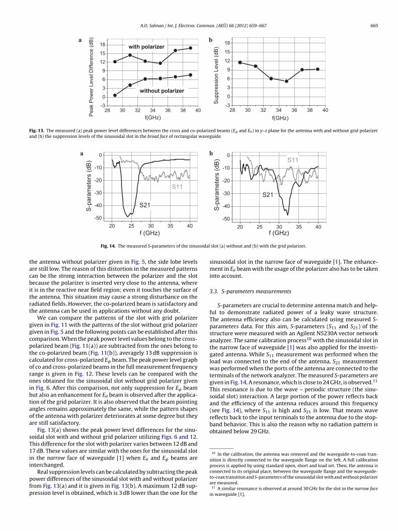
reflects back to the input terminals to the antenna due to the stop-band behavior. This is also the reason why no radiation pattern isobtained below 29 GHz.
10 In the calibration, the antenna was removed and the waveguide-to-coax tran-sition is directly connected to the waveguide flange on the left. A full calibrationprocess is applied by using standard open, short and load set. Then, the antenna is
f (GHz)
Fig. 14. The measured S-parameters of the sinu
he antenna without polarizer given in Fig. 5, the side lobe levelsre still low. The reason of this distortion in the measured patternsan be the strong interaction between the polarizer and the slotecause the polarizer is inserted very close to the antenna, where
t is in the reactive near field region; even it touches the surface ofhe antenna. This situation may cause a strong disturbance on theadiated fields. However, the co-polarized beam is satisfactory andhe antenna can be used in applications without any doubt.
We can compare the patterns of the slot with grid polarizeriven in Fig. 11 with the patterns of the slot without grid polarizeriven in Fig. 5 and the following points can be established after thisomparison. When the peak power level values belong to the cross-olarized beam (Fig. 11(a)) are subtracted from the ones belong tohe co-polarized beam (Fig. 11(b)), averagely 13 dB suppression isalculated for cross-polarized E� beam. The peak power level graphf co and cross-polarized beams in the full measurement frequencyange is given in Fig. 12. These levels can be compared with thenes obtained for the sinusoidal slot without grid polarizer givenn Fig. 6. After this comparison, not only suppression for E� beamut also an enhancement for E� beam is observed after the applica-ion of the grid polarizer. It is also observed that the beam pointingngles remains approximately the same, while the pattern shapesf the antenna with polarizer deteriorates at some degree but theyre still satisfactory.
Fig. 13(a) shows the peak power level differences for the sinu-oidal slot with and without grid polarizer utilizing Figs. 6 and 12.his difference for the slot with polarizer varies between 12 dB and7 dB. These values are similar with the ones for the sinusoidal slot
n the narrow face of waveguide [1] when E� and E� beams arenterchanged.
Real suppression levels can be calculated by subtracting the peakower differences of the sinusoidal slot with and without polarizerrom Fig. 13(a) and it is given in Fig. 13(b). A maximum 12 dB sup-ression level is obtained, which is 3 dB lower than the one for the
f (GHz)
slot (a) without and (b) with the grid polarizer.
sinusoidal slot in the narrow face of waveguide [1]. The enhance-ment in E� beam with the usage of the polarizer also has to be takeninto account.
3.3. S-parameters measurements
S-parameters are crucial to determine antenna match and help-ful to demonstrate radiated power of a leaky wave structure.The antenna efficiency also can be calculated using measured S-parameters data. For this aim, S-parameters (S11 and S21) of thestructure were measured with an Agilent N5230A vector networkanalyzer. The same calibration process10 with the sinusoidal slot inthe narrow face of waveguide [1] was also applied for the investi-gated antenna. While S11 measurement was performed when theload was connected to the end of the antenna, S21 measurementwas performed when the ports of the antenna are connected to theterminals of the network analyzer. The measured S-parameters aregiven in Fig. 14. A resonance, which is close to 24 GHz, is observed.11
This resonance is due to the wave – periodic structure (the sinu-soidal slot) interaction. A large portion of the power reflects backand the efficiency of the antenna reduces around this frequency(see Fig. 14), where S11 is high and S21 is low. That means wave
connected to its original place, between the waveguide flange and the waveguide-to-coax transition and S-parameters of the sinusoidal slot with and without polarizerare measured.
11 A similar resonance is observed at around 30 GHz for the slot in the narrow facein waveguide [1].
666 A.O. Salman / Int. J. Electron. Commu
20 25 30 35 40
0
20
40
60
80
100
w/o polarizer
with polarizer
f (GHz)
Ant
enna
effi
cien
cy (%
)
Fs
w
tt
P
wrpa
u
PTcn
a
t
e
iaisi
4
fraut
b[0tt
w
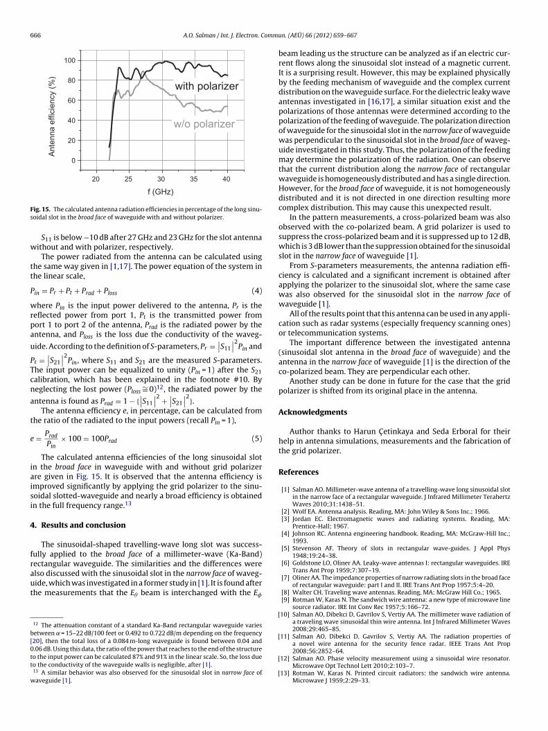
ig. 15. The calculated antenna radiation efficiencies in percentage of the long sinu-oidal slot in the broad face of waveguide with and without polarizer.
S11 is below −10 dB after 27 GHz and 23 GHz for the slot antennaithout and with polarizer, respectively.
The power radiated from the antenna can be calculated usinghe same way given in [1,17]. The power equation of the system inhe linear scale,
in = Pr + Pt + Prad + Ploss (4)
here Pin is the input power delivered to the antenna, Pr is theeflected power from port 1, Pt is the transmitted power fromort 1 to port 2 of the antenna, Prad is the radiated power by thentenna, and Ploss is the loss due the conductivity of the waveg-
ide. According to the definition of S-parameters, Pr =∣∣S11
∣∣2Pin and
t =∣∣S21
∣∣2Pin, where S11 and S21 are the measured S-parameters.
he input power can be equalized to unity (Pin = 1) after the S21alibration, which has been explained in the footnote #10. Byeglecting the lost power (Ploss
∼= 0)12, the radiated power by the
ntenna is found as Prad = 1 − {∣∣S11
∣∣2 +∣∣S21
∣∣2}.The antenna efficiency e, in percentage, can be calculated from
he ratio of the radiated to the input powers (recall Pin = 1),
= Prad
Pin× 100 = 100Prad (5)
The calculated antenna efficiencies of the long sinusoidal slotn the broad face in waveguide with and without grid polarizerre given in Fig. 15. It is observed that the antenna efficiency ismproved significantly by applying the grid polarizer to the sinu-oidal slotted-waveguide and nearly a broad efficiency is obtainedn the full frequency range.13
. Results and conclusion
The sinusoidal-shaped travelling-wave long slot was success-ully applied to the broad face of a millimeter-wave (Ka-Band)ectangular waveguide. The similarities and the differences were
lso discussed with the sinusoidal slot in the narrow face of waveg-ide, which was investigated in a former study in [1]. It is found afterhe measurements that the E� beam is interchanged with the E�12 The attenuation constant of a standard Ka-Band rectangular waveguide variesetween = 15–22 dB/100 feet or 0.492 to 0.722 dB/m depending on the frequency20], then the total loss of a 0.084 m-long waveguide is found between 0.04 and.06 dB. Using this data, the ratio of the power that reaches to the end of the structureo the input power can be calculated 87% and 91% in the linear scale. So, the loss dueo the conductivity of the waveguide walls is negligible, after [1].13 A similar behavior was also observed for the sinusoidal slot in narrow face ofaveguide [1].
[
[
[
[
n. (AEÜ) 66 (2012) 659– 667
beam leading us the structure can be analyzed as if an electric cur-rent flows along the sinusoidal slot instead of a magnetic current.It is a surprising result. However, this may be explained physicallyby the feeding mechanism of waveguide and the complex currentdistribution on the waveguide surface. For the dielectric leaky waveantennas investigated in [16,17], a similar situation exist and thepolarizations of those antennas were determined according to thepolarization of the feeding of waveguide. The polarization directionof waveguide for the sinusoidal slot in the narrow face of waveguidewas perpendicular to the sinusoidal slot in the broad face of waveg-uide investigated in this study. Thus, the polarization of the feedingmay determine the polarization of the radiation. One can observethat the current distribution along the narrow face of rectangularwaveguide is homogeneously distributed and has a single direction.However, for the broad face of waveguide, it is not homogeneouslydistributed and it is not directed in one direction resulting morecomplex distribution. This may cause this unexpected result.
In the pattern measurements, a cross-polarized beam was alsoobserved with the co-polarized beam. A grid polarizer is used tosuppress the cross-polarized beam and it is suppressed up to 12 dB,which is 3 dB lower than the suppression obtained for the sinusoidalslot in the narrow face of waveguide [1].
From S-parameters measurements, the antenna radiation effi-ciency is calculated and a significant increment is obtained afterapplying the polarizer to the sinusoidal slot, where the same casewas also observed for the sinusoidal slot in the narrow face ofwaveguide [1].
All of the results point that this antenna can be used in any appli-cation such as radar systems (especially frequency scanning ones)or telecommunication systems.
The important difference between the investigated antenna(sinusoidal slot antenna in the broad face of waveguide) and theantenna in the narrow face of waveguide [1] is the direction of theco-polarized beam. They are perpendicular each other.
Another study can be done in future for the case that the gridpolarizer is shifted from its original place in the antenna.
Acknowledgments
Author thanks to Harun C etinkaya and Seda Erboral for theirhelp in antenna simulations, measurements and the fabrication ofthe grid polarizer.
References
[1] Salman AO. Millimeter-wave antenna of a travelling-wave long sinusoidal slotin the narrow face of a rectangular waveguide. J Infrared Millimeter TerahertzWaves 2010;31:1438–51.
[2] Wolf EA. Antenna analysis. Reading, MA: John Wiley & Sons Inc.; 1966.[3] Jordan EC. Electromagnetic waves and radiating systems. Reading, MA:
Prentice-Hall; 1967.[4] Johnson RC. Antenna engineering handbook. Reading, MA: McGraw-Hill Inc.;
1993.[5] Stevenson AF. Theory of slots in rectangular wave-guides. J Appl Phys
1948;19:24–38.[6] Goldstone LO, Oliner AA. Leaky-wave antennas I: rectangular waveguides. IRE
Trans Ant Prop 1959;7:307–19.[7] Oliner AA. The impedance properties of narrow radiating slots in the broad face
of rectangular waveguide: part I and II. IRE Trans Ant Prop 1957;5:4–20.[8] Walter CH. Traveling wave antennas. Reading, MA: McGraw Hill Co.; 1965.[9] Rotman W, Karas N. The sandwich wire antenna: a new type of microwave line
source radiator. IRE Int Conv Rec 1957;5:166–72.10] Salman AO, Dibekci D, Gavrilov S, Vertiy AA. The millimeter wave radiation of
a traveling wave sinusoidal thin wire antenna. Int J Infrared Millimeter Waves2008;29:465–85.
11] Salman AO, Dibekci D, Gavrilov S, Vertiy AA. The radiation properties ofa novel wire antenna for the security fence radar. IEEE Trans Ant Prop
2008;56:2852–64.12] Salman AO. Phase velocity measurement using a sinusoidal wire resonator.Microwave Opt Technol Lett 2010;2:103–7.
13] Rotman W, Karas N. Printed circuit radiators: the sandwich wire antenna.Microwave J 1959;2:29–33.

ommu
[
[
[
[
[[
[
and international conferences. Dr. Salman is a Member of IEEE. He has 2000 and2005 TUBITAK-MRC Award for his success in two projects and “The Best Young Sci-entist Paper Award” in MSMW’01 (The Fourth International Kharkov Symposium– Physics and Engineering Millimeter and Sub-millimeter Waves) conference, in2001.
A.O. Salman / Int. J. Electron. C
14] Trentini VG. Flachantenne mit periodisch gebogenem Leiter. Frequenz1960;14:239–43.
15] Salman AO, Cetinkaya H, Vertiy AA. Actively and passively-excited sinusoidalmicrostrip and PCB strip antennas operating at K and millimeter-wave bands.Microwave Opt Technol Lett 2008;50:1302–8.
16] Salman AO. The millimeter wave radiation of a dielectric leaky-wave antennacoupled with a diffraction grating: broad-face interaction. J Infrared MillimeterTerahertz Waves 2010;31:196–213.
17] Salman AO. The millimeter wave radiation of a dielectric leaky-wave antennacoupled with a diffraction grating for the broadside radiation: narrow-faceinteraction. J Infrared Millimeter Terahertz Waves 2010;31:1032–47.
18] Balanis CA. Antenna theory. Reading, MA: Wiley; 2005.19] Borowick J, Stern RA, Rabbit RW, Bayka W. Inertialess scan antenna techniques
for millimeter waves. In: DARPA millimeter wave conf., U.S. Army missile com-mand. 1981. p. 20–2.
20] Balanis CA. Advanced engineering electromagnetic. Reading, MA: John Wiley& Sons Inc.; 1989.
A. Oral Salman was born in Ankara, Turkey, in 1969. Hereceived the B.Sc. and M.Sc. degrees in physics engineeringfrom Hacettepe University, Ankara, Turkey, in 1993 and1996, respectively. He received Ph.D. degree in electronicsand communication engineering from Kocaeli Universityin Kocaeli, Turkey, in 2006. Recently, he obtained hisAssociate Professorship of electrical and electronics engi-neering, in February 2011. He has been working as a Senior
Researcher at Marmara Research Center at ILHT (Interna-tional Laboratory of High Technology), UEKAE (NationalResearch Institute of Electronics and Cryptology), and BIL-GEM, which all belongs to TUBITAK in Kocaeli, Turkey,since 1999. He has been engaged with many military,n. (AEÜ) 66 (2012) 659– 667 667
government and industrial projects as Researcher and Co-Project Leader. Beforejoining TUBITAK, he worked as a Research and Teaching Assistant in HacettepeUniversity from 1994 to 1998. He visited ElectroScience Laboratory, in Colum-bus OH, USA between 2002 and 2003 as a visiting scholar. His research areasof interest include antenna theory, design and measurements, subsurface detec-tion, microwave diffraction tomography and imaging, electromagnetic theory, wavepropagation, electromagnetic properties of materials, RF coil and resonator designand magnetic resonance. He is the main author of a sub-chapter entitled “Diffrac-tion Multi-view Tomography Method in Microwave and Millimeter Wave Bands” inthe book “Subsurface Sensing” from Wiley, which is released in 2011. He is also theauthor of 12 papers printed in refereed journals and 21 oral presentations in national