A novel low-volume two-chamber microfabricated platform for evaluating drug metabolism and toxicity
Upload
independentCategory
view
4download
0
Talanta 63 (2004) 89–99
Microfabricated ISEs: critical comparison of inherently conductingpolymer and hydrogel based inner contacts
Róbert E. Gyurcsányia,1, Neeraja Rangisettyb, Sarah Cliftonc,Bradford D. Pendleyc, Ern"o Lindnerb,∗
a Institute of General and Analytical Chemistry, Budapest University of Technology and Economics, Szt. Gellért tér 4, H-1111 Budapest, Hungaryb Joint Graduate Program in Biomedical Engineering, The University of Memphis and University of Tennessee Health Science Center, Department of
Biomedical Engineering, Herff College of Engineering, University of Memphis, 330 Engineering Technology, Memphis, TN 38152-6582, USAc Rhodes College, 2000 North Parkway, Memphis, TN 38112, USA
Received 7 September 2003; received in revised form 25 November 2003; accepted 1 December 2003
Abstract
A rigorous side by side comparison of miniature planar potassium-selective electrodes with hydrogel and potassium hexacyanofer-rate(II)/(III) doped polypyrrole (PPy/FeCN) based inner contacts is presented. The planar electrodes were manufactured by screen printing asfour- and five-site arrays on ceramic substrates. These electrode arrays were incorporated into a flow-through cell, which could accommodatenine electrode sites. Two identical flow cells were connected in series and the effect of the inner contacts on the analytical performance ofthe respective electrodes has been critically evaluated. The time necessary to reach steady state conditions has been determined and the effectof experimental parameters (temperature, ambient light intensity, CO2, and O2 concentration of the sample) on the potential stability of theelectrodes was analyzed. At controlled temperature, the drift of the planar potassium electrodes with hydrogel and PPy/FeCN solid contactwere 0.11±0.02 mV h−1 and 0.03±0.007 mV h−1, respectively. The experimental data proved that there is no aqueous film formation betweenthe PPy/FeCN film and the potassium-selective solvent polymeric membrane.© 2003 Elsevier B.V. All rights reserved.
Keywords:Planar potassium selective electrode; Solid inner contact; Conductive polymer; PPy/FeCN; Hydrogel
1. Introduction
Ion-selective electrodes (ISEs) are now-a-days routineanalytical tools, with important applications in clinical di-agnostics, process monitoring and environmental analysis[1]. Over 60 inorganic and organic ions can be assesseddirectly with ion-selective (IS) electrodes and novel selec-tive ionophores[2] are continuously synthesized to enlargethis number. Recently, the detection limit (LOD) of ISEswas spectacularly improved[3–5] but the most importantapplication of ISEs remains the determination of clinicallyimportant cationic (e.g. K+, Na+, Ca2+, and H+) and an-ionic (Cl−) electrolytes and the CO2 concentration in bodyfluids [1]. In clinical chemistry blood electrolytes are almostexclusively assessed by ISEs, and therefore, ion-selective
∗ Corresponding author. Tel.:+1-901-678-5641;fax: +1-901-678-5281.
E-mail address:[email protected] (E. Lindner).1 Co-corresponding author.
potentiometry is among the most frequently used methodsin clinical chemistry. Microfabrication technologies haveentered the field of ion sensors with the implementation ofion-selective field effect transistors[6,7] and opened possi-bilities for real time, in vivo monitoring. The first flat-form,plastic membrane, potentiometric electrodes were perfectedin the early 1970s, by Eastman Kodak in its Ektachemproject[8]. By the late 1970s, numerous commercial deviceswere constructed using flow-through cells with miniatur-ized dip-style microelectrodes. Today, thick- and thin-filmprocessing provide mass produced microscale patterns[9]for different sensor applications in bioanalysis[8] and themodern versions of blood gas electrolyte analyzers alreadyuse flat-form microfabricated ion sensors[10]. However, thedramatic miniaturization, and the use of planar structuresinstead of the conventional three-dimensional electrode ar-rangements had its undesirable consequences. Planar sensorsprepared like “coated wire” electrodes[11,12], with no or ex-tremely small volume of inner filling solution were very sen-sitive to transmembrane fluxes, required longer equilibration
0039-9140/$ – see front matter © 2003 Elsevier B.V. All rights reserved.doi:10.1016/j.talanta.2003.12.002

90 R.E. Gyurcs´anyi et al. / Talanta 63 (2004) 89–99
(conditioning) time and were characterized with driftingpotentials and modest reproducibility. In addition, planarsensors were less reliable. Due to the formation of lowresistance shunts between the sensor membrane and thesensor substrate due to limited membrane adhesion[13].These unfavorable sensor properties are unacceptable inbiomedical applications, where the required coefficient ofvariations of intraday assays is less than 1%[14]. This re-quirement is challenging in whole blood, serum or plasmaelectrolyte analysis because the physiologically relevantcation (K+, Na+, Ca2+, and Mg2+) and anion (Cl− andHCO3
−) concentrations vary only in a narrow concentra-tion range. These concentration ranges translate to potentialspans from 2.3 mV (Ca2+ electrode) up to 9.1 mV (K+ sen-sor) which require ISEs with excellent reproducibility andnegligible drift [15].
To adapt the classical inner reference electrode construc-tion to the planar electrodes the large volume inner fill-ing solutions were replaced by thin hydrogel layers[16].Potassium and hydrogen ion-selective planar electrodes fab-ricated with these hydrogel layers provided potential stabil-ities in the order of 0.1 mV h−1 and were used successfullyin monitoring ion concentration changes in vivo[13]. How-ever, these hydrogel films have inherent limitations and theirbenefits faded away with decreasing sensor sizes (hydrogelvolumes). Efforts for replacing the conventional sensor de-sign are traced back to the earliest days of ISEs[17], be-cause the replacement of the inner filling solution by a solidcontact projected numerous advantages in design (smallersizes), sensor handling and applications leading to the de-velopment of high density ion sensor arrays[8,13]. How-ever, following the quick results with solid state ion-selectivemembranes[18] the attempts with solvent polymeric mem-branes encountered difficulties. The mismatch between ionconducting (IS membrane) and electron conducting phases(substrate electrode) resulted in large potential instabilities[19]. In order to maintain well defined potential differencesat the backside of the IS membrane reversible electron ex-change is required at the substrate electrode and reversibleion-exchange is required at the solid contact liquid mem-brane interface. The first approaches to achieve the goalof ionic to electronic transduction has been provided byinherently conducting polymers (CP), such as polypyrrole(PPy) [20–24], polyaniline[25,26], poly(3-octylthiophene)[27] and poly(3,4-ethylenedioxythiophene)[28,29]. Morerecently redox-active self-assembled monolayers have beenalso found to provide stable inner potential to polymericISEs [30]. However, the simplicity of site-specific electro-chemical deposition of conducting polymers in combinationwith their robustness, are proved advantages. Monolayershave limited stability and are sensitive to defects in theirstructure.
The properties of CP films are influenced by the dopingagent and the electropolymerization technique used for theirsynthesis. Large variety of doping agents (tetrafluoroborate[21], poly(4-styrenesulfonate)[31], hexacyanoferrate(II)
[23,24], chloride [20,23]) provided polypyrrole based H+[24], Na+ [21], K+ [20,31]selective ISEs of similar analyt-ical performance. Only the perchlorate and OH− ion dopedpolypyrrole based sensors were reported to be unsuitableas solid contact[22,24]. According to our knowledge it hasbeen only one attempt to implement CP based solid con-tacts in planar microfabricated ISEs[32]. To prove that CPsolid contact based ISEs meet the performance criteria re-quired in blood gas analyzers, their analytical performancehas been compared to analogous planar ISEs with hydrogelinner contact, which are already successfully applied incommercial blood gas analyzers. Among the possible solidcontact electrodes a potassium hexacyanoferrate(II)/(III)doped polypyrrole film (PPy/FeCN) was utilized, becausewe intended to have mobile K+ ions in the PPy film onthe back side of the potassium-selective poly(vinylchloride)(PVC) membrane to provide well defined potential at thePPy/potassium-selective membrane interface. PPy/FeCNfilms showed close to theoretical cationic responses, whichwas interpreted to be the result of the rather high content ofmobile potassium ions in the PPy film[33]. Large concen-tration hexacyanoferrate(II) and hexacyanoferrate(III) ionsin the PPy film was expected to act as a redox buffer inthe CP film. In addition, comparative studies suggest thatthe PPy/FeCN films provide the best analytical parameters[23,34]and they have been already applied for blood serummeasurements[23].
2. Experimental
2.1. Chemicals and reagents
Pyrrole obtained from Sigma Chemical Co. (St. Louis,MO, USA) was distilled prior to use. The freshly distilledpyrrole (Py) was then bubbled through with argon to removedissolved oxygen and was kept at low temperature, protectedfrom light. The components of the potassium-selective mem-brane: potassium(4-chlorphenyl)borate (KTpClPB), highmolecular weight poly(vinylchloride) and bis(2-ethylhexyl)sebacate (DOS) were obtained from Fluka (Buchs, Switzer-land), while valinomycin was from Sigma. Potassium hex-acyanoferrate(II) trihydrate (K4[Fe(CN)6]) was purchasedfrom Aldrich (Milwaukee, WI, USA). For electrode po-tential stability studies calibration solutions obtained fromInstrumentation Laboratory (Lexington, MA, USA) wereused. The ionic composition and the pH of the commercialtest solutions were: IL TESTTM CAL1 (pH 7.384, Na+140 mM, K+ 5 mM, Ca2+ 1 mM, Cl− 119 mM) and ILTESTTM CAL2 (pH 6.840, Na+ 100 mM, K+ 2 mM, Ca2+3 mM, Cl− 81 mM, glucose 90 mg dl−1). To test the carbondioxide dependency of the electrodes standard CAL1 solu-tions with 22.2 mmHg (pH 7.198), 51.5 mmHg (pH 6.960),and 69.7 mmHg (pH 7.167) CO2 partial pressure (pCO2)were prepared by bubbling CO2 gas through the IL TESTTM
CAL1 solution until the desired CO2 content was reached.

R.E. Gyurcs´anyi et al. / Talanta 63 (2004) 89–99 91
ThesepCO2 partial pressures correspond to the saturationvalues with gas mixtures containing 3, 5, or 8% (v/v) CO2(balance nitrogen), respectively. To set the pH and CO2content of the solutions an Instrumentation Laboratory Syn-thesis 35 blood electrolyte analyzer was used. The solutionswere stored in hermetically closed aluminum foil bags. ThepH and pCO2 values of the bags were controlled beforeuse. The solution in the bags could be accessed througha thick rubber septum with a syringe. All other reagentsand chemicals were of highest analytical grade availableand were purchased from Fluka. The solutions were pre-pared with Milli-Q Gradient A10 system (Millipore Corp.,Bedford, MA, USA) 18.2 M� cm resistivity deionizedwater.
2.2. The preparation of potassium-selective electrodes
2.2.1. Fabrication of the screen-printed silver andplatinum based electrodes
For the fabrication of hydrogel and polypyrrole basedinner contact ISEs, screen-printed silver and platinum elec-trodes were used, respectively. The cells were manufacturedon a laser prescribed, alumina substrate (Coors Ceramic,Grand Junction, CO, USA). The multiple sensor substrates(5.5 cm×2.3 cm) accommodated individual sensor chips of1 cm× 2.2 cm dimensions, organized as four- and five-sitesarrays. The single chips were either separated along thelaser prescribed lines or the four- and five-site arrays weredirectly inserted into a specially designed flow cell shown inFig. 1. A model MC810-C (C.W. Price Co., Bloomsbury, NJ,USA) screen printer was used to deposit the thick-film layersthrough stainless-steel wire mesh screens. The fabricationprocedure starts with the careful cleaning of the alumina
Fig. 1. Schematic diagram of the flow-trough cell setup and of the planar sensor arrays.
substrates. The wafers were sonicated in an ultrasonic bathfor 10 min in detergent, 10 min in acetone and finally for10 min in methanol. After each cleaning step the waferswere rinsed with deionized water, acetone and methanol,consecutively. A silver layer was deposited onto the aluminasurface to form the electrical contacts and the internal ref-erence electrode sites. A Metech 3571 silver ink (Metech,Inc., Elverson, PA, USA) was used in combination witha 325 mesh-count in.−1 screen (Microcircuit EngineeringCorp., Mount Holly, NJ, USA) and Five Star (AutotypeAmericas, Schaumburg, IL, USA) photosensitive emulsionfilm to define the pattern. The silver layer was fired for 9 minin a programmable muffle furnace at a peak temperatureof 850◦C. Similar cleaning procedures preceded the print-ing of the platinum electrodes. The platinum ink (HeraeusLP11-4493, West Conshohocken, PA) was printed througha 325-mesh screen (Microcircuit Engineering Corp.) andallowed first to level at room temperature for 10 min, then itwas dried at 150◦C for 10 min and fired in a programmablemuffle furnace at 1050◦C for 12 min. The dimensionsof both the silver and platinum electrode sites have beendetermined by printing four to six layers of insulator ma-terial (glass-ceramic dielectric, Metech 7600 A) through a200-mesh screen. The glassy dielectric material insulatedthe conductive path of the electrodes between the boundingpads and the disc-shaped electrodes sites (2 mm diameter)on the bottom of 80–120�m deep “wells”. Each layer wasallowed to level at room temperature and then dried in ovenat 150◦C for 10 min. The final, multi-layer structure wasfired at 850◦C for 7 min. The characteristic dimensionsof the base electrodes were determined with a high reso-lution profilometer (model Alpha-Step 500, KLA-Tencor,San Jose, CA, USA). Electrical contact was made to each

92 R.E. Gyurcs´anyi et al. / Talanta 63 (2004) 89–99
of the sensors by soldering copper wires to the boundingpads, which were subsequently sealed with a thin layer ofsilicone rubber (Dow Corning® 3140 MIL-A-46146 RTV).
2.2.2. Preparation of the internal contacts
2.2.2.1. Preparation of the potassium hexacyanofer-rate(II)/(III) doped polypyrrole (PPy/FeCN) solid contacts.The PPy/FeCN films were prepared onto screen-printed Ptelectrodes by potentiostatic electropolymerization from anaqueous solution containing 0.5 M pyrrole monomer and0.5 M potassium hexacyanoferrate(II). The monomer so-lution was purged with ultra high purity nitrogen beforepolymerization and nitrogen was flushed over the solu-tion during polymerization. The electropolymerization wasperformed in a three-electrode electrochemical cell by ap-plying 1 V potential versus a Ag/AgCl reference electrode(BAS, West Lafayette, IN, USA) for 60 s (182 mC), 90 s(220 mC), 120 s (351 mC) or 180 s (458 mC) (typically90 s) using a personal computer controlled PAR 273 A po-tentiostat (Princeton Applied Research, Oak Ridge, TN).Generally two to five individual electrodes of the four- orfive-site arrays (Fig. 1) were electrically connected togetherand the deposition of the PPy/FeCN film was performedsimultaneously on the interconnected electrodes of the cor-responding array. A rectangular shaped well was designed(8.2 cm long, 0.8 cm wide and 1.2 cm deep) and fabricatedto accommodate the electrode arrays during polymerizationand to minimize the volume of the monomer solution re-quired. The electropolymerization resulted in a∼10–25�mthick PPy/FeCN layer on the surface of the screen-printedPt electrodes as determined with a profilometer. The elec-trodes were rinsed with water after removing them from thepolymerization bath. The film was dried at room tempera-ture and then small aliquots of tetrahydrofuran were appliedover the PPy/FeCN films to remove residual traces of water.
2.2.2.2. Preparation of the hydrogel based inner contact.First the screen-printed silver electrodes were cleaned in anultrasonic bath by immersing the electrodes alternately intodeionized water and methanol. Next, silver chloride (AgCl)was deposited over the silver electrodes by immersing thefour- and five-site arrays into a solution of 0.1 M NaCl andapplying a current of 0.03 mA per sensor for 5 min. Forthe preparation of the hydrogel based inner contacts thescreen-printed silver electrodes were drop cast with a hydro-gel solution. Two grams of poly(2-hydroxyethyl methacry-late) was dissolved in 5.4 g of methanol. One milliliter ofthis stock solution was doped with 500�l electrolyte so-lution (140 mM NaCl and 1 mM KCl). About halve mi-croliter (0.52�l) of this hydrogel solution was depositedin each sensor well using a 1�l syringe. The amount ofpoly(2-hydroxyethyl methacrylate) deposited in the well isexpected to fill the well in its completely hydrated state. Thesalt concentration of the hydrogel was designed to osmoti-cally balance the CAL1 solution.
2.2.3. Casting the ion-selective membrane onto theinternal contact
The potassium-selective membrane cocktail consisted of2.01 mg valinomycin; 0.49 mg KTpClPB, 99.95 mg PVCand 199.91 mg DOS. The membrane components were dis-solved in 2 ml cyclohexanone. Seven microliters from themembrane cocktail was applied over the sensing areas in-dependent of the internal contact used. The cyclohexanonebased membrane cocktail was also spread over the surround-ing insulation layer to enhance the contact surface for ISmembrane adhesion and minimize the possibility of the for-mation of low resistance water shunts between the mem-brane and the ceramic substrate. Once dry, 7�l membranecocktail was applied a second time. This second membranelayer prevented sensor failures related to eventual small pin-holes and proved to be advantageous for better fitting (seal-ing) with the zig-zag flow channel (Fig. 1).
2.2.3.1. Preparation of the coated wire electrodes.Thecoated wire electrodes were prepared in similar way but themembrane cocktail was applied directly onto the platinumor Ag/AgCl surface.
2.3. Multielectrode flow-through system
As it is shown inFig. 1 a four- and a five-site array withnine potassium electrodes or nine individual potassium elec-trodes were incorporated into a flow-through cell (Instru-mentation Laboratory)[35]. The four- and five-site arraysor the individual sensor chips were mechanically pressedagainst the flow channel with the ion-selective membranesfacing the flow channel to seal the fluid path, i.e. the sen-sor arrays or the individual sensor chips sandwiched thezig-zag flow channel made of Plexi-glass. The mechanicalpressure was applied with silicone rubber springs, leaningagainst the inner wall of the cell housing made of anodizedaluminum. In the zig-zag flow channel only a small cen-tral fraction (∼1 mm2) of the sensor membrane surface isexposed to the sample. The major part of the sensing mem-brane (∼20 mm2) acts as fitting between the flow channeland the screen-printed sensor substrate. Consequently in thisarrangement the ratio of the exposed membrane surface com-pared to the total membrane volume is very small, i.e. themembrane bulk acts as a reservoir for the membrane ingre-dients if the dissolution of these ingredients into the samplecan not be prevented.
Two identical flow cells, housing 18 electrodes, were con-nected in series. A Minipuls 3 peristaltic pump (Gilson Inc.,Middleton, WI) was used to stream the solution. For poten-tiometric measurements the electrodes in conjunction withan Instrumentation Laboratory (model 70975-00) saturatedAg/AgCl reference electrode in a home made flow-throughcell were connected to a 16 channel high input impedancedata acquisition system (Lawson Labs Inc., Malvern, PA)running on a Dell Pentium-II 300 MHz computer. Thereference electrode was placed downstream with respect of
R.E. Gyurcs´anyi et al. / Talanta 63 (2004) 89–99 93
the flow-through ISEs to avoid the bias related to potassiumion leakage from the reference electrode.
3. Results and discussion
The flow-through manifold shown inFig. 1 allows rig-orous side by side comparison of the short- and long-term,behavior of sensors in the flow channel. The test solution incontact with the studied sensors is continuously renewed byslow rate pumping. The flowing solution contacts the differ-ent electrodes in the zig-zag channel practically at the sametime. The sensors are at the same temperature and the hous-ing protects the sensors from direct light. Sensor failures re-lated to membrane delamination are prevented by using thesensing membranes as fittings between the flow channel andthe sensor substrate.
3.1. Electrode preconditioning: required equilibration timefor high stability potential measurements
The advantages of the solid contact ISEs are well docu-mented in the literature. Surprisingly, the equilibration timeneeded by a mirofabricated, planar ISE before it achieves op-timal analytical performance is hardly considered. However,in real analytical scenarios, this is a very important parame-ter because it is desired to have functional electrodes instan-taneously after they have been removed from their package.Long equilibration times are often unacceptable in medicalapplications. Planar sensors with hydrogel inner contact areoften accompanied with severe positive potential drifts afterthe first contact with solution. During storage, the hydrogellayer of such electrodes looses water which is regained dur-ing preconditioning as water is transported across the mem-brane by diffusion until the osmotic equilibrium between thetwo sides of the membrane is reached. The rehydration ofthe hydrogel gradually decreases the primary ion activity inthe inner solution compartment which produces the positivepotential drift. This problem has been addressed by storingthe electrodes in containers with 100% humidity, which re-duced the preconditioning time from hours to a few minutes[36]. The equilibration time for solid contact electrodes isexpected to be much shorter compared to hydrogel contactedelectrodes.
To provide data supporting the expected advantages ofplanar sensors with solid inner contact, two batches of
Table 1Short-term stability of planar potassium-selective electrodes with different inner contacts recorded in IL TESTTM CAL1 solution (pH 7.384, Na+ 140 mM,K+ 5 mM, Ca2+ 1 mM, Cl− 119 mM)
Inner contact N Average drift
mV per 30 min mV h−1 R.S.D. (%) mV per 9 h mV h−1
Hydrogel 7 9.7 19.4 93.8 72.8 8.1PPy/FeCN 8 −5.8 −11.6 24.5 −18.2 −2.0Coated wire 1 −9.3 −18.6 – −25.6 −2.8
The potential changes (�E) and the average drifts were determined for the first 30 min and the first 9 h after solution contact.
freshly prepared electrodes with hydrogel and PPy/FeCNinner contact were assembled in the flow-through systemand the potential response of the unconditioned electrodeswas recorded in CAL1 solution. The total potential changes(�E) recorded in the first 30 min and the average drifts de-termined in the first 9 h of conditioning are summarized inTable 1. During the first conditioning period the potentialof “coated wire” and the PPy/FeCN solid contact electrodesdecreased, while the potential of hydrogel contacted elec-trodes increased. The negative potential drift experiencedwith the PPy/FeCN based electrodes is in agreement withthe theoretical expectations[33] for PPy films preparedwith oxidative polymerization. The positive potential driftof the electrodes with hydrogel inner contact is relatedto the water uptake of the inner hydrogel layer as it wasdiscussed earlier. The driving force for the water transportthrough the ion-selective membrane is the osmotic pressuredifference at the two sides of the membrane.
As expected, the potential drift for the PPy/FeCN solidcontact electrodes was significantly smaller than for ISEswith hydrogel inner contact. The average drift for the first30 min and the relative standard deviation (R.S.D.) of thedrift for PPy/FeCN based solid contact electrodes is muchsmaller than in case of hydrogel based electrodes (seeTable 1). After 9 h of continuous contact with CAL1 so-lution the drift of the PPy/FeCN solid contact electrodeswas only−2.0 mV h−1 compared with 8.1 mV h−1 for thehydrogel based internal contact electrodes (Table 1). In ad-dition, the drift values of the electrodes with hydrogel innercontact showed large standard deviation (93.8%). We as-sume that this is due to variations of the ion-selective mem-brane thickness. The potential values of the hydrogel basedinner contact electrodes showed smaller R.S.D. (10.1%or 7.2 mV, Eav = −71.1 mV) compared to the PPy/FeCNbased electrodes (29.3%, or 24.3 mV,Eav = 83.1 mV)at the first contact with the CAL1 solution. However, atthe end of the 9 h conditioning the deviation of the po-tential values for hydrogel based inner contact electrodes(S.D. = 24 mV) surpassed that of the PPy/FeCN electrodes(S.D. = 19.8 mV).
Long time dry storage reduced the equilibration timenecessary for high stability measurements, decreased thedrift and improved the reproducibility of the potential val-ues of the PPy/FeCN based solid contact electrodes. Byrepeating the equilibration (“conditioning”) experiments

94 R.E. Gyurcs´anyi et al. / Talanta 63 (2004) 89–99
after 1 year dry storage (in dark, but otherwise normal labo-ratory conditions) the direction of the potential drift was thesame, but its value was only−1.1 mV in the first 30 min,which is five times smaller then that of the freshly preparedelectrodes. Moreover the R.S.D. of the potential values forthe same electrode batch dropped from 29.3% (S.D. =24.3 mV) to 6.6% (S.D. = 11.2 mV). Finally, the poten-tial stability of the fully conditioned electrodes was foundless than 0.03 mV h−1 in a 72 h experiment (much smallerthan 0.1 mV h−1 calculated for the hydrogel contactedISEs).
It is well documented that the PPy films undergo somecomplicated equilibration processes after their prepara-tion. These include redox reactions, polymer capacitancedischarge and structural and conformational changes. Theeffect of these processes on the open circuit potential wasstudied under different experimental conditions includingthe polymer film thickness, the composition and pH of theaqueous electrolyte in contact with the film, and the pres-ence of oxygen[33,37,38]. The experimentally recordedpotential changes were traced back to changes in the poly-mer composition due to spontaneous charging/dischargingprocess between the PPy film and the bathing solution.Although, in our system the PPy/FeCN film is coatedwith a hydrophobic, permselective membrane, apparently,these processes contributed to some kind of equilibrationin the plasticized PVC-coated PPy/FeCN films during theextended “dry storage” which decreased the differencesamong the electrodes (the measured potential values of indi-vidual electrodes became closer to each other) and reducedthe drift of the measured potentials during first conditioningand continuous measurements.
These data suggest that the preparation procedure forpreparing the PPy/FeCN contacts can be further improved.
25
75
125
175
225
275
0 2 4 6 8 10 12 14 16 18 20 22 24
Time / h
E /
mV
hydrogel
PPy/FeCN
60s
90s
120s
180s
Fig. 2. Short-term stability of freshly prepared (unconditioned) PPy/FeCN and hydrogel based inner contact planar, potassium-selective electrodes inCAL1 solution (pH 7.384, Na+ 140 mM, K+ 5 mM, Ca2+ 1 mM, Cl− 119 mM). The effect of the electropolymerization time used for the preparationof the PPy/FeCN films on the potential response of the corresponding potassium electrodes is illustrated.
In Fig. 2, the potential time recordings of different planarelectrodes with solid and hydrogel inner contact are com-pared. The PPy/FeCN based solid contacts were depositedapplying 1 V with different electrolysis times (charges) rang-ing from 60 to 180 s (from 182 to 458 mC, respectively).The PPy film thickness and the extent of overoxidation ofthe PPy film increases with increasing electropolymeriza-tion time. Apparently, there is a clear correlation betweenthe electroplymerization time and drift recorded during thefirst conditioning period. Electrodes prepared with longerelectropolymerization time showed smaller drift. This is inagreement with the experimental findings of Bobacka[28]who showed clear relationship between the thickness of theCP, i.e. the redox capacitance of the inner contact, and thepotential stability of the CP based solid contact electrodes.The overoxidized form of polypyrrole is thermodynamicallymore stable than the highly conducting PPy film. Longer de-position times increase the overoxidized fraction of PPy inthe film which is supposed to be also advantageous for theincreased potential stability.
3.2. Potential response of planar ISEs with PPy/FeCN andhydrogel contacts
The response slope of the different electrodes was evalu-ated through a two point calibration in a narrow concentra-tion range relevant to the potassium content of the humanblood. IL TESTTM CAL1 and CAL2 solutions with 2 and5 mM K+ concentrations were used for these experiments.Electrodes with theoretical, Nernstian response slopes areexpected to show a potential change (�E) of 23.54 mV be-tween CAL1 and CAL2 solutions. As it can be seen inTable 2, regardless of the inner contact the response slopeswere close to the theoretical Nernstian value. The R.S.D. of

R.E. Gyurcs´anyi et al. / Talanta 63 (2004) 89–99 95
Table 2Potential response of planar potassium-selective electrodes with differentinner contacts due to 3 mM change in the K+ ion concentration (ILTESTTM CAL1 and CAL2 solutions with 2 and 5 mM K+)
Coated wire PPy/FeCN Hydrogel
�Emean (mV) 22.8 23.4 22.7S.D. (mV) 0.2 0.3 0.4R.S.D. (%) 0.7 1.2 1.5
The data shown in the table are the mean values of seven consecutiveconcentration steps.
the response slopes were between 0.5 and 1.5%, which isacceptable in clinical analysis.
3.3. Effect of carbon dioxide and oxygen on the potentialstability
The potential of ISEs is expected to be stable at constanttemperature as long the composition of the contacting so-lutions and the membrane is constant. Drifting potentialsrelated to transmembrane transport are experienced duringanion and cation interference and when neutral moleculessuch as water, O2, or CO2, are transported through the highlyplasticized polymeric membranes used for ISE fabrication.The carbon dioxide dependency of the different planar ISEswas determined by pumping solutions of constant potas-sium concentrations but different CO2 content through theflow channel. Differences in the potential transients duringthe experiment are indicative of the CO2 sensitivity of the
0 100 200 300 400 500 600 700
50
75
100
125
150
175
200
hydrogel
Cal1
3 % CO2
Cal1
5 % CO2
8 % CO2
5 % CO2
3 % CO2
E /
mV
time, min
PPy/FeCN
coated wire
Fig. 3. Effect of the carbon dioxide concentration of the sample solution onto the potential stability of potassium-selective electrodes based on differentinner contacts.
inner contacts.Fig. 3 shows the trace recording during theCO2 study. Only the coated wire electrodes had a signifi-cant CO2 interference. This interference appeared to be re-versible, however, with a severe hysteresis when switchingfrom higher CO2 content solutions to lower ones. The CO2interference on the potential stability of CP based electrodeswas explained by pH changes provoked at the CP solid con-tact after the diffusion of CO2 across the PVC membrane[29]. The prevention of a water film formation between theCP solid contact and the sensing membrane is expected tobe advantageous for minimizing the CO2 interference.
Since oxygen can readily permeate through solvent poly-meric membranes it is essential to determine the oxygensensitivity of different solid contact electrodes. The interfer-ence of oxygen on the response of coated wire ion-selectiveelectrodes and the factors influencing its magnitude arecomprehensively discussed in the literature[39]. It hasbeen related to the formation of an oxygen half-cell at thesubstrate electrode surface, which is obviously very sus-ceptible to fluctuations in the oxygen content of the samplesolutions[39]. Unfortunately, it is quite difficult to get clearguidance from the literature on the oxygen sensitivity ofsolid contact electrodes based on conducting polypyrrolefilms since this seems to depend on the doping anion andexperimental conditions, particularly on the CP film thick-ness. For the Pt/PPy/BF4
− solid contact sodium-selectiveelectrodes Cadogan et al.[21] have reported no signifi-cant oxygen sensitivity. The same group in a more recentpaper showed that potassium-selective electrodes basedon poly(4-styrenesulfonate) doped PPy films (PPy/PSS)

96 R.E. Gyurcs´anyi et al. / Talanta 63 (2004) 89–99
0 25 50 75 100 125 150 175 200100
105
110
115
120
125Cal1
E /
mV
time/ min
coated wire
PPy/FeCN
N2
N2
Fig. 4. Effect of the oxygen concentration of the sample onto the potential stability of PPy/FeCN-contacted potassium-selective electrodes. For aneasieroverview the potential–time curves recorded with different electrodes were superposed by shifting the potential values.
deposited on glassy carbon electrodes have marked oxygensensitivity [29]. In this last report switching from oxy-genated to deoxygenated solutions resulted in potentialdrifts exceeding 25 mV h−1. However, the large oxygen sen-sitivity was experienced with a much thinner PPy/PSS film[29] than PPy/BF4− film (7–10�m) [21] which showed nooxygen dependence. The difference in the PPy film thick-ness may at least partly explain the differences in oxygensensitivity. Appropriate redox buffering of the CP film isexpected to minimize the effect of oxygen on the electrodepotential of solid contact electrodes. It can be achieved bydoping the film with large concentration of redox mediatorlike hexacyanoferrate(II) and hexacyanoferrate(III).
To study the oxygen dependency of the solid contact elec-trodes air or N2 saturated solutions were pumped throughthe flow channel alternatively while the electrode potentialswere recorded (Fig. 4). Switching from deaerated to aeratedsolution did not influence the potential of thep-HEMAbased electrodes (data not shown). The PPy solid contactelectrodes, showed slight oxygen sensitivity. The averagepotential drift of the PPy/FeCN based planar sensors dueto the deaeration of the solution was−2.5 mV h−1. The O2interference was found similar to the data reported for thePPy/BF4
− based solid contact sodium electrode[21] butwas smaller than it was experienced with the PPy/PSS filmbased potassium sensor[29]. However, PPy film thicknesswas much thinner in the work of Vázquez et al.[29] than inthe work of Cadogan et al.[21] (7–10�m) or in the presentstudy (10–25�m). The variations in the potential drift of theindividual electrodes is relatively small (R.S.D. = 17.6%)and is probably due to variation in the transmembraneoxygen flux as an effect of differences in the membrane
thickness. The beneficial effect of the PPy/FeCN contact isunambiguous when comparing with the coated wire typeelectrodes exhibiting severe O2 interference. The potentialof the coated wire electrodes drifted−8.31 mV within 1 hdue to deaeration of the solution.
3.4. Effect of temperature on the potential stability
The effect of temperature on the measured potentialsis of primary importance if the solid contact sensors areaimed for in vivo applications with no possibility for pre-cise temperature control. To study the effect of temperaturefluctuations on the potential response of planar ISEs the en-tire flow-through manifold (solution container, flow-throughcell, and the reference electrode) was placed into a tem-perature controlled water bath. The measurements wereperformed in the dark to avoid possible interference fromchanging light intensities in the room. The temperature ofthe bath was set to 37◦C and kept constant until completeequilibration. The electrode potentials were recorded for aminimum of 30 min after complete equilibration. Next, thetemperature was decreased in two steps (�t1 = 4◦C and�t2 = 7◦C) by adding ice to the water bath. The electrodepotentials were recorded continuously until stabilized po-tential response was reached. The electrode potentials ofplanar ISEs with PPy/FeCN contact increased+3.8 mV dueto a 4◦C decrease in the temperature of the thermostatingbath. At the same time the electrode potentials of planarISEs with hydrogel inner contact decreased by−1.15 mV,corresponding to+ 0.95 mV◦C−1 and−0.29 mV◦C−1 tem-perature coefficients, respectively. The 7◦C temperature de-crease caused proportionally larger changes in the electrode
R.E. Gyurcs´anyi et al. / Talanta 63 (2004) 89–99 97
potentials. Accordingly, the temperature coefficients werefound practically the same as in the previous experiment:+1.01 and−0.24 mV◦C−1 for the PPy and hydrogel innercontact based ISEs, respectively. A negative drift of theISEs with the hydrogel inner contact could be interpreted aschanges in the standard potential of the inner Ag/AgCl/Cl−reference system[40]. However, this interpretation cannot be made unambiguously since the introduced tempera-ture changes influenced both the planar ISEs and theflow-through reference electrode filled with saturated KClsolution. Although the complexity of the measuring sys-tem is not suitable to sort out the individual contributionsto the subtle temperature effects on the electrode poten-tials, it is clear that for proper potential stability a rigoroustemperature control is essential. For a 0.1 mV precisionin the electrode potential measurement of the polypyrrolebased solid contact electrodes the temperature must be keptconstant within 0.1◦C.
3.5. Effect of ambient light on the potential stability
Similar to the effect of CO2 and O2 on the potential stabil-ity of solid contact electrodes the light sensitivity of solventpolymeric ISEs is traced back to changes in the compositionof the contacting phases. As long the membrane ingredientscan be considered photostable, potential instabilities expe-rienced during ambient light intensity fluctuations can betraced to the effect of light on the inner reference (redox) sys-tem. Although the inner reference electrodes are generallyeffectively protected from the ambient light its influence un-der practical conditions can not always be eliminated. In oursystem the flow cell housing protects the ISEs from direct
105
110
115
120
125
130
135
140
145
150
0.0 0.5 1.0 1.5 2.0
Time / h
E /
mV
Flash light ON
Flash light OFF Room light ON Room light OFF
PPy/FeCN
hydrogel
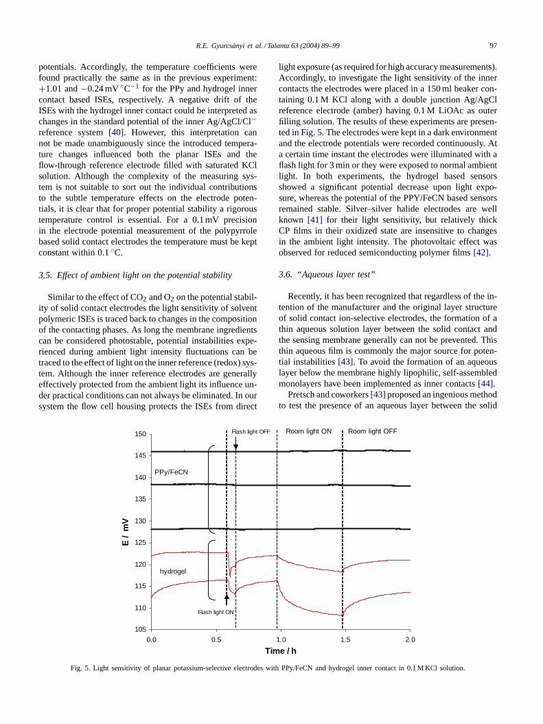
Fig. 5. Light sensitivity of planar potassium-selective electrodes with PPy/FeCN and hydrogel inner contact in 0.1 M KCl solution.
light exposure (as required for high accuracy measurements).Accordingly, to investigate the light sensitivity of the innercontacts the electrodes were placed in a 150 ml beaker con-taining 0.1 M KCl along with a double junction Ag/AgClreference electrode (amber) having 0.1 M LiOAc as outerfilling solution. The results of these experiments are presen-ted inFig. 5. The electrodes were kept in a dark environmentand the electrode potentials were recorded continuously. Ata certain time instant the electrodes were illuminated with aflash light for 3 min or they were exposed to normal ambientlight. In both experiments, the hydrogel based sensorsshowed a significant potential decrease upon light expo-sure, whereas the potential of the PPY/FeCN based sensorsremained stable. Silver–silver halide electrodes are wellknown [41] for their light sensitivity, but relatively thickCP films in their oxidized state are insensitive to changesin the ambient light intensity. The photovoltaic effect wasobserved for reduced semiconducting polymer films[42].
3.6. “Aqueous layer test”
Recently, it has been recognized that regardless of the in-tention of the manufacturer and the original layer structureof solid contact ion-selective electrodes, the formation of athin aqueous solution layer between the solid contact andthe sensing membrane generally can not be prevented. Thisthin aqueous film is commonly the major source for poten-tial instabilities[43]. To avoid the formation of an aqueouslayer below the membrane highly lipophilic, self-assembledmonolayers have been implemented as inner contacts[44].
Pretsch and coworkers[43] proposed an ingenious methodto test the presence of an aqueous layer between the solid

98 R.E. Gyurcs´anyi et al. / Talanta 63 (2004) 89–99
-60
-10
40
90
140
190
240
290
340
0 4 8 12 16 20 2Time / h
E /
mV
0.1M NaCl 0.1M KCl
4
Hydrogel
PPy/FeCN
Fig. 6. Aqueous layer formation test: typical potential traces of planar potassium-selective electrodes with PPy/FeCN and hydrogel contact when thesample solution is changed from 0.1 M NaCl to 0.1 M KCl. Before the experiment all electrodes were conditioned in 0.1 M NaCl for 24 h.
contact and the IS membrane. By alternately exposing theelectrodes to samples containing high concentration of pri-mary and interfering ions, the presence of an aqueous layeris indicated by positive potential drifts when changing fromthe primary ion to the interfering ion and negative potentialdrifts in the reverse case. As expected the planar electrodeswith hydrogel inner contact exhibited severe potentialdrifts in these tests when the solutions were switched from0.1 M NaCl to 0.1 M KCl or vice versa.Fig. 6 shows unam-biguously that there is no aqueous layer formation betweenthe IS membrane and PPy/FeCN film. Eventually this isthe first report that succeeded to avoid the formation of anaqueous layer when using highly plasticized PVC as matrixfor the IS membrane. Previous studies showed that even inthe case of highly lipophilic self-assembled monolayers theformation of the aqueous layer could not be avoided whenconventional highly plasticized PVC membranes were used[30].
The heavily doped polypyrrole films are clearly less lipo-hilic than hexadecanethiol layers used by the Pretsch andcoworkers[44], therefore, these results are surprising. How-ever, in the special flow-through setup the membrane is notonly held by adhesion forces on the inner contact but theclamping device exercises also a strong mechanical force,which presses the membrane to the substrate electrode andthe flow-through cell. It is obvious that this results in a bettercontact between the polypyrrole film and the IS membrane,and most likely this is the explanation for the absence of theaqueous layer.
4. Conclusion
The rigorous side by side comparison of PPy/FeCN andhydrogel contacted potassium ISE demonstrated the suit-
ability of these electrodes for high precision potentiometricmeasurements under carefully controlled experimental con-ditions. The planar electrodes manufactured with PPy/FeCNsolid contact were found superior compared to the elec-trodes fabricated with hydrogel inner contact in severaltests. The preconditioning time to achieve stable potentialsis shorter and the long-term potential stability is better prob-ably because the solid contact electrodes are not susceptibleto osmolality changes of the sample solution. Finally, thePPy/FeCN electrodes are not light sensitive.
However, in other tests, the hydrogel based ISEs provedto have advantages. They were insensitive to changes inthe oxygen concentration of the sample, while the poten-tial of the PPy/FeCN based ISEs were slightly affected. ThePPy/FeCN based ISEs have also larger temperature coeffi-cients, although this can be compensated with rigorous ther-mostating.
This work has also demonstrated the significance of theexperimental setup, i.e. the special zig-zag flow channel inwhich a mechanical force is utilized for clamping the mem-brane coated electrodes. The mechanical force presses thesensing membrane against the flow channel and its solidcontact. The latter is assumed to be essential in preventingan aqueous layer formation between the highly plasticizedPVC membrane and the solid contact and prevents electrodefailures related to non adequate membrane adhesion to thesensor substrate. Finally the results suggest that the prepara-tion of CP films can be further improved for better analyticalresponse of the corresponding ISEs.
Acknowledgements
This work was supported in part by the National ScienceFoundation 0202207 and 0335228, MTA 87 and OTKA:

R.E. Gyurcs´anyi et al. / Talanta 63 (2004) 89–99 99
NSF 46146 grants. R.E.G. gratefully acknowledges the Wil-helm Simon, Bolyai János and Varga József (Balla György)fellowships as well as the financial support of the Hungar-ian Science Foundation (F037977, F034431, and M041969).The authors would like to thank Professor E. Pretch andJolanda Sutter for helpful discussions.
References
[1] E. Bakker, P. Buhlmann, E. Pretsch, Chem. Rev. 97 (1997) 3083.[2] P. Buhlmann, E. Pretsch, E. Bakker, Chem. Rev. 98 (1998) 1593.[3] T. Sokalski, A. Ceresa, T. Zwickl, E. Pretsch, J. Am. Chem. Soc.
119 (1997) 11347.[4] E. Bakker, E. Pretsch, Anal. Chem. 74 (2002) 420A.[5] E. Lindner, R.E. Gyurcsanyi, R.P. Buck, Electroanalysis 11 (1999)
695.[6] P. Bergveld, IEEE Trans. Biomed. Eng. 19 (1972) 342.[7] P. Bergveld, IEEE Trans. Biomed. Eng. 17 (1970) 70.[8] E. Lindner, R.P. Buck, Anal. Chem. 72 (2000) 336A.[9] J. Voldman, M.L. Gray, M.A. Schmidt, Annu. Rev. Biomed. Eng.
01 (1999) 401–425.[10] I.R. Lauks, Acc. Chem. Res. 37 (1998) 317.[11] R.W. Cattrall, I.C. Hamilton, Ion-Selective Electrode Rev. 6 (1984)
125.[12] R.W. Cattrall, H. Freiser, Anal. Chem. 43 (1971) 1905.[13] E. Lindner, V.V. Cosofret, S. Ufer, R.P. Buck, R.P. Kusy, R.B. Ash,
H.T. Nagle, J. Chem. Soc. Faraday Trans. 89 (1993) 361.[14] E. Bakker, D. Diamond, A. Lewenstam, E. Pretsch, Anal. Chim.
Acta 393 (1999) 11.[15] P.C. Meier, D. Amman, W.E. Morf, W. Simon, in: J. Koryta (Ed.),
Medical and Biological Applications of Electrochemical Devices,Wiley, Chichester, New York, Brisbane, Toronto, 1980, p. 13.
[16] E. Lindner, V.V. Cosofret, S. Ufer, T.A. Johnson, R.B. Ash, H.T.Nagle, M.R. Neuman, R.P. Buck, Fresenius J. Anal. Chem. 346(1993) 584.
[17] C.Z. Trümpler, Z. Electroch. 30 (1924) 103.[18] H. Hirata, K. Date, Talanta 17 (1970) 883.[19] R.P. Buck, Anal. Chem. 48 (1976) R23.[20] R.E. Gyurcsanyi, A.S. Nyback, K. Toth, G. Nagy, A. Ivaska, Analyst
123 (1998) 1339.[21] A. Cadogan, Z.Q. Gao, A. Lewenstam, A. Ivaska, D. Diamond, Anal.
Chem. 64 (1992) 2496.
[22] T. Momma, M. Yamamoto, S. Komaba, T. Osaka, J. Electroanal.Chem. 407 (1996) 91.
[23] A. Michalska, A. Hulanicki, A. Lewenstam, Microchem. J. 57 (1997)59.
[24] A. Michalska, A. Hulanicki, A. Lewenstam, Analyst 119 (1994)2417.
[25] J. Bobacka, T. Lindfors, M. McCarrick, A. Ivaska, A. Lewenstam,Anal. Chem. 67 (1995) 3819.
[26] G. Cui, J.S. Lee, S.J. Kim, H. Nam, G.S. Cha, H.D. Kim, Analyst123 (1998) 1855.
[27] J. Bobacka, M. McCarrick, A. Lewenstam, A. Ivaska, Analyst 119(1994) 1985.
[28] J. Bobacka, Anal. Chem. 71 (1999) 4932.[29] M. Vázquez, J. Bobacka, A. Ivaska, A. Lewenstam, Sens. Actuators
B—Chem. 82 (2002) 7.[30] M. Fibbioli, K. Bandyopadhyay, S.G. Liu, L. Echegoyen, O. Enger,
F. Diederich, D. Gingery, P. Buhlmann, H. Persson, U.W. Suter, E.Pretsch, Chem. Mater. 14 (2002) 1721.
[31] T. Momma, S. Komaba, M. Yamamoto, T. Osaka, S. Yamauchi, Sens.Actuators B—Chem. 25 (1995) 724.
[32] R. Zielinska, E. Mulik, A. Michalska, S. Achmatowicz, M. Maj-Zurawska, Anal. Chim. Acta 451 (2002) 243.
[33] A. Michalska, A. Ivaska, A. Lewenstam, Anal. Chem. 69 (1997)4060.
[34] A. Michalska, A. Konopka, M. Maj-Zurawska, Anal. Chem. 75(2003) 141.
[35] C. Bergkuist, R.P. Buck, V.V. Cosofret, C.-C. Liu, R.A. Lucic, J.P.Moriarty, M.R. Neuman, R.M. Bucchianeri, US Patent 6,123,820,2000.
[36] V.V. Cosofret, M. Erdosy, E. Lindner, T.A. Johnson, R.P. Buck, W.J.Kao, M.R. Neuman, J.M. Anderson, Anal. Lett. 27 (1994) 3039.
[37] J. Dumanska, K. Maksymiuk, Electroanalysis 13 (2001) 567.[38] E. Krivan, C. Visy, J. Kankare, J. Phys. Chem. B 107 (2003) 1302.[39] R.W. Cattrall, D.M. Drew, I.C. Hamilton, Anal. Chim. Acta 76 (1975)
269.[40] D.J.G. Ives, G.J. Janz, Reference Electrodes, Theory and Practice,
Academic Press, New York, 1961.[41] A.W. Copeland, O.D. Black, A.B. Garrett, Chem. Rev. 31 (1942)
177.[42] U. Rammelt, S. Bischoff, M. El-Dessouki, R. Schulze, W. Plieth, L.
Dunsch, J. Solid State Electrochem. 3 (1999) 406.[43] M. Fibbioli, W.E. Morf, M. Badertscher, N.F. de Rooij, E. Pretsch,
Electroanalysis 12 (2000) 1286.[44] M. Fibbioli, K. Bandyopadhyay, S.G. Liu, L. Echegoyen, O. Enger,
F. Diederich, P. Buhlmann, E. Pretsch, Chem. Commun. (2000) 339.
Copyright © 2022 FDOKUMEN