
Methodology for Optimal Mast and Standing Rigging Selection of a Racing Yacht Using AHP and FEM
11
11 64(2013)1, 11-21 UDC 629.5.01:629.5.026.8:519.6 Albert ZAMARIN 1 Tin MATULJA 2 Marko HADJINA 3 Methodology for Optimal Mast and Standing Rigging Selection of a Racing Yacht Using AHP and FEM Original scientific paper The racing yacht design process, except the hull and appendages, involves the selection of sails, rigging and mast. Proper selection and scantling calculations of the mast and standing rig- ging is of crucial importance as it is the backbone and connection of sail driving load transferred to the hull. Optimal selection within a racing yacht is even more important because of the fact that such yachts are operated by professional crews that are capable to get out the maximum of the ship and its masts and rigging. Thus in this paper the authors present a novel methodology for the optimal selection of a mast and standing rigging based on the procedure in three main phases by using AHP method through the first two phases and FEM analysis in the last one. The first phase includes identification of possible design solutions, while the second one searches for the best design configuration and determines the stability of the chosen solution. The third phase is used for load calculations, scantlings determination, and final approval of the project variables. The proposed methodology is applied and tested on the selection of mast and standing rigging of a 40-foot racing yacht. Keywords: AHP optimization, design methodology, FEM analysis, mast and rigging, racing yacht Prijedlog metodologije za optimalni odabir jarbola i nepomične opute regatne jedrilice korištenjem AHP i FEM Izvorni znanstveni rad Proces projektiranja regatne jedrilice, osim trupa i privjesaka, podrazumijeva odabir i projekt snasti, tj. jedrilja, opute i jarbola. Pravilni odabir i dimenzioniranje jarbola i nepomične opute od presudne je važnosti budući da predstavljaju oslonac i vezu prijenosa opterećenja ‘pogona’ od jedrilja na trup. Regatnim jedrilicama upravlja uglavnom stručnija posada koja je sposobna od broda, pa tako i od jarbola i opute, izvući maksimum čime pravilan odabir dobiva još više na važnosti. U radu je prikazana metodologija za optimalan odabir jarbola i nepomične opute primjenom AHP metode kroz prve dvije faze i FEM analize u trećoj fazi. Prva faza uključuje identifikaciju mogućih projektnih rješenja, druga faza podrazumijeva odabir optimalne projektne konfiguracije i utvrđivanje stabilnosti odabranog rješenja, dok treća faza služi za proračun opterećenja, dimenzioniranje i konačno usvajanje projektnih varijabli. Predložena metodologija primijenjena je i provjerena na odabiru jarbola i nepomične opute 40-stopne regatne jedrilice. Ključne riječi: AHP optimizacija, FEM analiza, jarbol i oputa, projektna metodologija, regatna jedrilica Authors’ address: 1,2,3 Faculty of Engineering, University of Rijeka Department of Naval Architecture and Ocean Engineering Vukovarska 58, 51000 Rijeka e-mail addresses: zamarin@riteh. hr, [email protected], hadjina@ riteh.hr Received (Primljeno): 2012-10-24 Accepted (Prihvaćeno): 2012-10-30 Open for discussion (Otvoreno za raspravu): 2014-03-31 1 Introduction Mast design for standard sailing yachts usually consists of a number of procedures based on empirical equations from relevant marine standards, rules and regulations, which are leading to the mast selection meeting aimed sail yacht charac- teristics [1]. However, mast selected in such way, will usually be of standard material and configuration that lead to a heavier mast and rigging. In such approach, inevitably, resulting mast structure will not be optimal and sail yacht performances will be decreased. Such procedure is often used for cruising sail yachts because it is fast and cheap [2]. However, for prototype racing yachts even before structural design, it is necessary to identify some other design variables such as: mast and rigging material, mast configuration, sail plan and deck configuration. If the design is constrained with the existing hull and append- ages, optimisation procedure can develop towards three main directions regarding: material selection, specific competition regulations and structural design. Therefore, in this paper, authors are proposing a novel meth- odology for determining optimal mast configuration, implement- ing the procedure consisting of three main phases, using specific
-
Upload
independent -
Category
Documents
-
view
0 -
download
0
Transcript of Methodology for Optimal Mast and Standing Rigging Selection of a Racing Yacht Using AHP and FEM
1164(2013)1, 11-21
METHODOLOGY FOR OPTIMAL MAST AND STANDING RIGGING... A. ZAMARIN, T. MATULJA, M. HADJINAUDC 629.5.01:629.5.026.8:519.6
Albert ZAMARIN1
Tin MATULJA2
Marko HADJINA3
Methodology for Optimal Mast and Standing Rigging Selection of a Racing Yacht Using AHP and FEM
Original scientifi c paper
The racing yacht design process, except the hull and appendages, involves the selection of sails, rigging and mast. Proper selection and scantling calculations of the mast and standing rig-ging is of crucial importance as it is the backbone and connection of sail driving load transferred to the hull. Optimal selection within a racing yacht is even more important because of the fact that such yachts are operated by professional crews that are capable to get out the maximum of the ship and its masts and rigging. Thus in this paper the authors present a novel methodology for the optimal selection of a mast and standing rigging based on the procedure in three main phases by using AHP method through the fi rst two phases and FEM analysis in the last one. The fi rst phase includes identifi cation of possible design solutions, while the second one searches for the best design confi guration and determines the stability of the chosen solution. The third phase is used for load calculations, scantlings determination, and fi nal approval of the project variables. The proposed methodology is applied and tested on the selection of mast and standing rigging of a 40-foot racing yacht.
Keywords: AHP optimization, design methodology, FEM analysis, mast and rigging, racing yacht
Prijedlog metodologije za optimalni odabir jarbola i nepomične opute regatne jedrilice korištenjem AHP i FEM
Izvorni znanstveni rad
Proces projektiranja regatne jedrilice, osim trupa i privjesaka, podrazumijeva odabir i projekt snasti, tj. jedrilja, opute i jarbola. Pravilni odabir i dimenzioniranje jarbola i nepomične opute od presudne je važnosti budući da predstavljaju oslonac i vezu prijenosa opterećenja ‘pogona’ od jedrilja na trup. Regatnim jedrilicama upravlja uglavnom stručnija posada koja je sposobna od broda, pa tako i od jarbola i opute, izvući maksimum čime pravilan odabir dobiva još više na važnosti. U radu je prikazana metodologija za optimalan odabir jarbola i nepomične opute primjenom AHP metode kroz prve dvije faze i FEM analize u trećoj fazi. Prva faza uključuje identifi kaciju mogućih projektnih rješenja, druga faza podrazumijeva odabir optimalne projektne konfi guracije i utvrđivanje stabilnosti odabranog rješenja, dok treća faza služi za proračun opterećenja, dimenzioniranje i konačno usvajanje projektnih varijabli. Predložena metodologija primijenjena je i provjerena na odabiru jarbola i nepomične opute 40-stopne regatne jedrilice.
Ključne riječi: AHP optimizacija, FEM analiza, jarbol i oputa, projektna metodologija, regatna jedrilica
Authors’ address:1,2,3 Faculty of Engineering, University
of Rijeka
Department of Naval Architecture
and Ocean Engineering
Vukovarska 58, 51000 Rijeka
e-mail addresses: zamarin@riteh.
hr, [email protected], hadjina@
riteh.hr
Received (Primljeno): 2012-10-24
Accepted (Prihvaćeno): 2012-10-30
Open for discussion (Otvoreno za
raspravu): 2014-03-31
1 Introduction
Mast design for standard sailing yachts usually consists of a number of procedures based on empirical equations from relevant marine standards, rules and regulations, which are leading to the mast selection meeting aimed sail yacht charac-teristics [1]. However, mast selected in such way, will usually be of standard material and confi guration that lead to a heavier mast and rigging. In such approach, inevitably, resulting mast structure will not be optimal and sail yacht performances will be decreased. Such procedure is often used for cruising sail
yachts because it is fast and cheap [2]. However, for prototype racing yachts even before structural design, it is necessary to identify some other design variables such as: mast and rigging material, mast confi guration, sail plan and deck confi guration. If the design is constrained with the existing hull and append-ages, optimisation procedure can develop towards three main directions regarding: material selection, specifi c competition regulations and structural design.
Therefore, in this paper, authors are proposing a novel meth-odology for determining optimal mast confi guration, implement-ing the procedure consisting of three main phases, using specifi c
12 64(2013)1, 11-21
A. ZAMARIN, T. MATULJA, M. HADJINA METHODOLOGY FOR OPTIMAL MAST AND STANDING RIGGING...
methods, such as Analytical Hierarchy Process (AHP) and Finite Element Method (FEM).
Material selection in case of racing yacht is an important parameter within mast design and its equipment. A lighter mast leads to the smaller infl uence on the sail yacht angle of heel and moments of inertia and hydrodynamic characteristics will improve. The consequence is application of aluminium alloys for mast construction and stainless steel ropes and steel bars for standing riggings. The ultimate racing masts are made of carbon fi bres and special light composite ropes for standing and running rigging [3]. Masts made from carbons fi bres are lighter and have the same or even better mechanical characteristics compared to aluminium alloys masts, but the price is signifi cantly higher as well as impact on specifi c competition regulations [4].
Furthermore, within sailing racing events signifi cant diversity in hull form, racing yachts dimensions, sails, and equipment can be observed. Therefore, an obvious question arises: When different racing yachts compete between each other is it predict-able that a bigger and faster racing yacht will reach the fi nish line fi rst? Solution for such situation is founded in confi guring special competition rules, respectively the handicap systems, which should in theory allow the equal chance for all yachts regardless racing yacht dimensions and characteristics. Within such handicap system the competition standings are calculated using “corrected time” generated by using calculated factors for each particular yacht. To determine how a single characteristic of the racing yacht is infl uencing its performances is a problem that has been tried to be solved since 1881, when such handicap system was introduced in Great Britain for the fi rst time. Until today, a number of handicap systems have been introduced, however, only ORC international handicap system is based on a scientifi c approach. Therefore, ORCi handicap system best suits the real life situation introducing completely new approaches in racing yacht measuring and calculating the “corrected time”. This handicap system is not dealing with direct racing yacht comparison but is using mathematical model and large racing yachts database, which includes the hull form, stability, sail plan, etc. in order to calculate theoretical yacht speed for each wind speed and angle [5]. In such way the theoretical time for completing the race course is calculated for each yacht in the race. In theory a racing yacht will have as better corrected time as the crew will sail closest to the calculated theoretical time for their particular yacht. Practice has proven that certain racing yachts characteristics and equipment confi guration are especially favourably infl uencing the racing yacht performances within used handicap system because of obvious limitations of existing mathematical model and used data base. Hence, the authors are especially emphasizing the importance of proposed methodol-ogy where such handicap limitations can be integrated in mast confi guration selection.
Final design aspect is a structural strength assessment. The mast and rigging in design have a great infl uence on racing yachts performances, fi rstly because of the height of the centre of gravity that decreases yacht stability, then because its defl ec-tion under loads infl uences the fl ying shape of the sail and hence the sail effi ciency. The mast designer has thus to deal with two opposite objectives: to obtain a lightweight structure, with a low centre of gravity that can be effi ciently controlled by the crew, and to obtain enough robustness to handle all the conditions that the yacht may encounter. To face that challenge, mast design-
ers have traditionally two main kinds of tools: Finite Element Method (FEM) or Euler’s Formulas modifi ed and adopted for easy use through classifi cation rules and regulations [6], [7] and [8]. The fi rst method represents the state of the art of structural engineering and provides very good results as long as loads are accurate. Practically, these methods are only used to check the validity of a candidate design or to, carry out a refi ned analysis of a design before construction. The second method, the use of Euler's Formulas, which deals with mast stability, in combination with designer’s experience, appears to be a "rule of thumb" and leads to over built rigs and overestimated safety coeffi cients as to avoid any risk of failure due to the various approximations made along the design process. In this context the proper combina-tion of these two tools may lead to satisfactory results, because it eliminates the need for complex and expensive aerodynamic and hydrodynamic load models. In such a way it is important to prepare correct structural model for a FEM analysis using all the capabilities of a modeller and the FEM software.
2 Methodology for optimal mast and stand-ing rigging selection of a racing yacht
A novel methodology for racing yacht mast and rigging se-lection is based on conducting three phases to reach an optimal design solution. Such design solution is the basis for further technical documentation development.
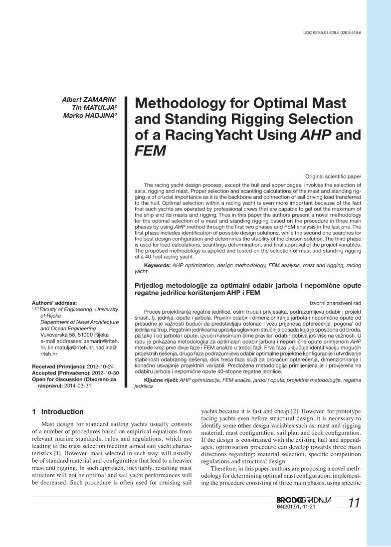
The procedure, methods and techniques of the developed meth-odology are explained in this section. Furthermore, the proposed methodology pattern of the procedure is shown in Figure 1.
Figure 1 Proposed methodology Pattern of Procedures Slika 1 Shematski prikaz procedura predložene metodologije
1364(2013)1, 11-21
METHODOLOGY FOR OPTIMAL MAST AND STANDING RIGGING... A. ZAMARIN, T. MATULJA, M. HADJINA
2.1 Possible design solutions identifi cation - phase I
Within the fi rst phase of the developed methodology the de-sign solutions are identifi ed based on possible mast and rigging design variables. Such variables are: mast material, mast profi le length and cross section design, number of spreaders, position of the mast foot step, rigging material, and sail plan confi guration. All possible solutions include combinations of the mentioned variables. The number of possible different design solutions can be more than 300, but there are practical constraints that reduce this number to most feasible ones.
The criteria in most cases will be analysed through the infl u-ence on sailing performance, handicap system, building costs, useful exploitation life time, and maintenance costs, Table 1. Each criterion will have particular weight factor K
i calculated
by expert approach within AHP method [9].
Table 1 Proposed criteria for further calculationsTablica 1 Prijedlog kriterija za daljnji proračun
Criterion number
Criterion nameCriterion weight factor
1 Infl uence on sailing performance K1
2 Infl uence on handicap system K2
3 Infl uence on building and maintenance costs
K3
4 Infl uence on useful exploitation life time
K4
Constraints in considerations will normally suggest no more than n=50 most feasible design solutions i.e. design alternatives, Table 2.
Table 2 Possible design solutions, alternativesTablica 2 Moguća projektna rješenja, alternative
Alternative
Mast characteristics
Mast material
Mast length, m
Rigging material
No. of spreaders
1 Mast 1 L1 Rig 1 1
2 Mast 2 L2
Rig 2 2
3 . . . .
. Mast m Ls
Rig r p
. . . . .
. Mast 1 L1 Rig 1 1
. Mast 2 L2
Rig 2 2
n-1 . . . .
n Mast m Ls
Rig r p
2.2 Optimal confi guration selection – phase II
2.2.1 Optimal confi guration selection applying AHP
In the second phase of the proposed methodology, for optimal design solution selection, the authors suggest using Analytical Hierarchy Process (AHP) [9]. The AHP method as one of multi-attribute decision making approaches is a structured technique for dealing with complex decisions. Rather than prescribing a
“correct” decision, the AHP helps the decision makers fi nd the one that best suits given constraints (criteria). In order to select the optimal design among previously selected probable solutions it is necessary to involve relevant constraints which this design has to satisfy optimally. These criteria are included in AHP model de-velopment and based on them an optimal solution, as the method goal, will be found among the chosen design solutions.
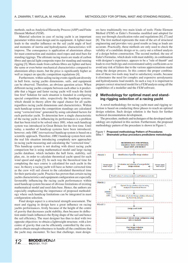
Hierarchical model structurally consists of the following levels: goal, criteria, sub-criteria and alternatives, Figure 2. The goal is placed on the highest hierarchical level and it is not com-pared to any other element of the hierarchical structure. On the fi rst level there are k criteria which are compared to each other in pairs regarding the directly superior element – goal. The k · (k - 1)/2 of comparison is required. The same procedure is repeated for the next hierarchical level, all the way down to the last r level, until all comparisons of all solutions with respect to the superior criteria, down to r-1 level, is completed.
Figure 2 AHP hierarchical modelSlika 2 AHP hijerarhijski model
Each comparison of two elements of the hierarchical model is done by Saaty’s scale of relative importance as shown in [9]. The results of elements comparison on the observed hierarchical level are organised in matrix form as follows:
If n elements are compared to each other with respect to the superior corresponding element on a higher hierarchical level, then, when comparing i element to j element using Saaty’s scale of relative importance, numerical coeffi cient a
ij is determined
and placed in its adequate position in matrix A:
(1)
Inverse result value is placed on position aji as to maintain
consistency of decision making. Detailed description of AHP method can be found in [9] and [10].
The authors used specialised software, ExpertChoice11, [11] for solving the considered case study. Based on determined priorities the solution with the highest value is selected and such solution is considered to be the optimal one.
(2)
GOAL
CRITERIA No. 1 CRITERIA No. i CRITERIA No. k
ALTERNATIVE No. 1 ALTERNATIVE No. j ALTERNATIVE No. m
...
.................. ..................
Sub-criteria Sub-criteria ...Sub-criteria Sub-criteria
...........................................................................................................................................
.
...........................................................................................................................................
... ...
...Sub-criteria Sub-criteria
level 1
level 2
level r-1
level r
A
a a a
a a a
a a a
n
n
n n nn
=
⋅ ⋅⋅ ⋅
⋅ ⋅ ⋅⋅ ⋅ ⋅
⋅ ⋅
⎡
⎣
11 12 1
21 22 2
1 2
⎢⎢⎢⎢⎢⎢⎢
⎤
⎦
⎥⎥⎥⎥⎥⎥
P A K A K A K A Ki i i i i= ⋅ + ⋅ + ⋅ + ⋅− − − −1 1 2 2 3 3 4 4
14 64(2013)1, 11-21
A. ZAMARIN, T. MATULJA, M. HADJINA METHODOLOGY FOR OPTIMAL MAST AND STANDING RIGGING...
2.2.2 Stability determination of chosen solution by sensitivity analysis
To conclude if the suggested rank list of the design solution is stable, the Sensitivity Analysis (SA) is conducted. Sensitivity Analysis belongs to Operation Research methods within linear programming and is used for analysing how changes of model parameters are infl uencing the optimal solution [12].
There are two types of SA as follows [13]:- Analytical SA, used for well defi ned systems and solving
problem using partial derivation (3),
(3)
where S defi nes sensitivity function (change intensity) of goal function F related to changes of parameter x.
- Empirical SA, used when the infl uence of parameter values change on optimal solution is analysed by experiments, such type of SA is more applicable to complex systems [13].
Within the proposed methodology the empirical SA is sug-gested because the mast and rigging confi guration present a complex system that cannot be analytically well defi ned [13]. For conducting SA the Expert Choice software can be used with the following empirical SA types: Dynamic, Performance, Gradient and Head to Head analysis [11]. Using SA within phase 2, the selected optimal design solution can be confi rmed as stable and therefore as a fi nal solution being an input for the fi nal phase. In case that the solution is not stable, i.e. there are two or more solutions with the same priority value, the iteration loop returns towards the previous phase for further analysis of criteria and the weight factors, Figure 1.
2.3 Strength assessment – phase III
Strength assessment - phase III, within the proposed method-ology represents a part of a standard theory for marine structural design procedure [14]. Mast and rigging, as marine structural elements are subjected to ultimate strength and fatigue assess-ment, as well as to structural reliability. These particular tasks
are included by applying safety coeffi cients (panel factor, staying factor, etc.) through available standards and rules. Therefore, they are within safety margins, and could be improved. Although the ultimate strength and fatigue are recognised as design drivers in the design process, the present methodology can be extended to the future work. A standard FEM analysis, together with ultimate strength and fatigue would make the main loop in the optimisa-tion process. But this could be done for the case of completely new racing yacht design that is not constrained with existing hull parameters.
2.3.1 Design load model
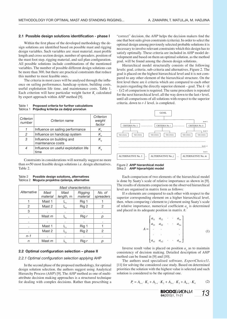
One of the major issues when dealing with mast design is the ability of the designer to defi ne design or maximal loads applied on the structure. To determine the sail loads on the rigging, a load model is to be developed based on the yacht performance. Therefore, various velocity prediction programs [5], [15], [16] are used for the prediction of forces generated by each sail, Figure 3, [15]. Later on these forces are translated to forces acting on the mast and rigging. For a sailing yacht rigging the following conditions, which a robust mast has to be able to face, belong to the critical ones: closed hauled, broad reach, and running under spinnaker.
The fi rst and the most important step in all these conditions, with small exceptions for downwind, is to evaluate the transversal force T
f on each sail and its centre of effort CoE
m,s,f, Figure 4. The
sum of each sail moment has to balance the righting moment RM of the yacht depending on the sailing condition:
(4)
Once the transversal force on a sail is known, the distribution of the loads at the sail corners with respect to the sail balance has to be performed. As the sail has a quite high aspect ratio, one can assume that the clew and tack points are located at the same heights. That load is then applied to the node carrying the headsails stay, or it is distributed on small portion of the mast at
SF
xxF = ∂
∂,
7
Figure 3 Centre of efforts, sail areas, and load transfer from sails to mast and riggingSlika 3 Položaji težišta i površine jedara i prijenos sila na jarbol i oputu
SF
xxF = ∂
∂,
T m f sA RM
A CoE Hfm f s
i ii m f s
, , , ,
, ,
( ) =−( )
=∑
1564(2013)1, 11-21
METHODOLOGY FOR OPTIMAL MAST AND STANDING RIGGING... A. ZAMARIN, T. MATULJA, M. HADJINA
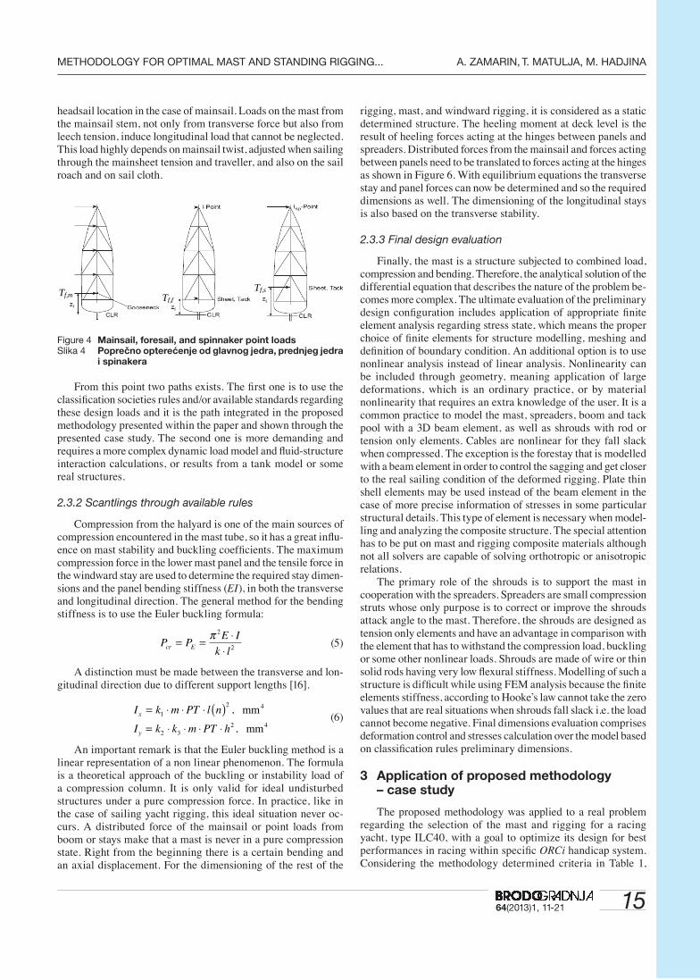
headsail location in the case of mainsail. Loads on the mast from the mainsail stem, not only from transverse force but also from leech tension, induce longitudinal load that cannot be neglected. This load highly depends on mainsail twist, adjusted when sailing through the mainsheet tension and traveller, and also on the sail roach and on sail cloth.
Figure 4 Mainsail, foresail, and spinnaker point loadsSlika 4 Poprečno opterećenje od glavnog jedra, prednjeg jedra
i spinakera
From this point two paths exists. The fi rst one is to use the classifi cation societies rules and/or available standards regarding these design loads and it is the path integrated in the proposed methodology presented within the paper and shown through the presented case study. The second one is more demanding and requires a more complex dynamic load model and fl uid-structure interaction calculations, or results from a tank model or some real structures.
2.3.2 Scantlings through available rules
Compression from the halyard is one of the main sources of compression encountered in the mast tube, so it has a great infl u-ence on mast stability and buckling coeffi cients. The maximum compression force in the lower mast panel and the tensile force in the windward stay are used to determine the required stay dimen-sions and the panel bending stiffness (EI), in both the transverse and longitudinal direction. The general method for the bending stiffness is to use the Euler buckling formula:
(5)
A distinction must be made between the transverse and lon-
gitudinal direction due to different support lengths [16].
(6)
An important remark is that the Euler buckling method is a
linear representation of a non linear phenomenon. The formula is a theoretical approach of the buckling or instability load of a compression column. It is only valid for ideal undisturbed structures under a pure compression force. In practice, like in the case of sailing yacht rigging, this ideal situation never oc-curs. A distributed force of the mainsail or point loads from boom or stays make that a mast is never in a pure compression state. Right from the beginning there is a certain bending and an axial displacement. For the dimensioning of the rest of the
rigging, mast, and windward rigging, it is considered as a static determined structure. The heeling moment at deck level is the result of heeling forces acting at the hinges between panels and spreaders. Distributed forces from the mainsail and forces acting between panels need to be translated to forces acting at the hinges as shown in Figure 6. With equilibrium equations the transverse stay and panel forces can now be determined and so the required dimensions as well. The dimensioning of the longitudinal stays is also based on the transverse stability.
2.3.3 Final design evaluation
Finally, the mast is a structure subjected to combined load, compression and bending. Therefore, the analytical solution of the differential equation that describes the nature of the problem be-comes more complex. The ultimate evaluation of the preliminary design confi guration includes application of appropriate fi nite element analysis regarding stress state, which means the proper choice of fi nite elements for structure modelling, meshing and defi nition of boundary condition. An additional option is to use nonlinear analysis instead of linear analysis. Nonlinearity can be included through geometry, meaning application of large deformations, which is an ordinary practice, or by material nonlinearity that requires an extra knowledge of the user. It is a common practice to model the mast, spreaders, boom and tack pool with a 3D beam element, as well as shrouds with rod or tension only elements. Cables are nonlinear for they fall slack when compressed. The exception is the forestay that is modelled with a beam element in order to control the sagging and get closer to the real sailing condition of the deformed rigging. Plate thin shell elements may be used instead of the beam element in the case of more precise information of stresses in some particular structural details. This type of element is necessary when model-ling and analyzing the composite structure. The special attention has to be put on mast and rigging composite materials although not all solvers are capable of solving orthotropic or anisotropic relations.
The primary role of the shrouds is to support the mast in cooperation with the spreaders. Spreaders are small compression struts whose only purpose is to correct or improve the shrouds attack angle to the mast. Therefore, the shrouds are designed as tension only elements and have an advantage in comparison with the element that has to withstand the compression load, buckling or some other nonlinear loads. Shrouds are made of wire or thin solid rods having very low fl exural stiffness. Modelling of such a structure is diffi cult while using FEM analysis because the fi nite elements stiffness, according to Hooke’s law cannot take the zero values that are real situations when shrouds fall slack i.e. the load cannot become negative. Final dimensions evaluation comprises deformation control and stresses calculation over the model based on classifi cation rules preliminary dimensions.
3 Application of proposed methodology – case study
The proposed methodology was applied to a real problem regarding the selection of the mast and rigging for a racing yacht, type ILC40, with a goal to optimize its design for best performances in racing within specifi c ORCi handicap system. Considering the methodology determined criteria in Table 1,
Tf,m Tf,f
Tf,s
P PE I
k lcr E= = ⋅⋅
π 2
2
I k m PT l n
I k k m PT h
x
y
= ⋅ ⋅ ⋅ ( )= ⋅ ⋅ ⋅ ⋅
1
2
2 32
,
,
mm
mm
4
4
16 64(2013)1, 11-21
A. ZAMARIN, T. MATULJA, M. HADJINA METHODOLOGY FOR OPTIMAL MAST AND STANDING RIGGING...
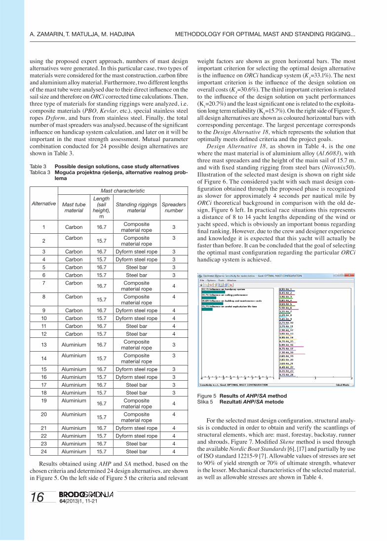
using the proposed expert approach, numbers of mast design alternatives were generated. In this particular case, two types of materials were considered for the mast construction, carbon fi bre and aluminium alloy material. Furthermore, two different lengths of the mast tube were analysed due to their direct infl uence on the sail size and therefore on ORCi corrected time calculations. Then, three type of materials for standing riggings were analyzed, i.e. composite materials (PBO, Kevlar, etc.), special stainless steel ropes Dyform, and bars from stainless steel. Finally, the total number of mast spreaders was analysed, because of the signifi cant infl uence on handicap system calculation, and later on it will be important in the mast strength assessment. Mutual parameter combination conducted for 24 possible design alternatives are shown in Table 3.
Table 3 Possible design solutions, case study alternativesTablica 3 Moguća projektna rješenja, alternative realnog prob-
lema
Alternative
Mast characteristic
Mast tube material
Length (sail
height), m
Standing riggings material
Spreaders number
1 Carbon 16.7Composite
material rope3
2Carbon
15.7Composite
material rope3
3 Carbon 16.7 Dyform steel rope 3
4 Carbon 15.7 Dyform steel rope 3
5 Carbon 16.7 Steel bar 3
6 Carbon 15.7 Steel bar 3
7 Carbon16.7
Composite material rope
4
8 Carbon15.7
Composite material rope
4
9 Carbon 16.7 Dyform steel rope 4
10 Carbon 15.7 Dyform steel rope 4
11 Carbon 16.7 Steel bar 4
12 Carbon 15.7 Steel bar 4
13 Aluminium 16.7Composite
material rope3
14Aluminium
15.7Composite
material rope3
15 Aluminium 16.7 Dyform steel rope 3
16 Aluminium 15.7 Dyform steel rope 3
17 Aluminium 16.7 Steel bar 3
18 Aluminium 15.7 Steel bar 3
19 Aluminium16.7
Composite material rope
4
20 Aluminium15.7
Composite material rope
4
21 Aluminium 16.7 Dyform steel rope 4
22 Aluminium 15.7 Dyform steel rope 4
23 Aluminium 16.7 Steel bar 4
24 Aluminium 15.7 Steel bar 4
Results obtained using AHP and SA method, based on the chosen criteria and determined 24 design alternatives, are shown in Figure 5. On the left side of Figure 5 the criteria and relevant
weight factors are shown as green horizontal bars. The most important criterion for selecting the optimal design alternative is the infl uence on ORCi handicap system (K
2=33.1%). The next
important criterion is the infl uence of the design solution on overall costs (K
3=30.6%). The third important criterion is related
to the infl uence of the design solution on yacht performances (K
1=20.7%) and the least signifi cant one is related to the exploita-
tion long term reliability (K4=15.7%). On the right side of Figure 5,
all design alternatives are shown as coloured horizontal bars with corresponding percentage. The largest percentage corresponds to the Design Alternative 18, which represents the solution that optimally meets defi ned criteria and the project goals.
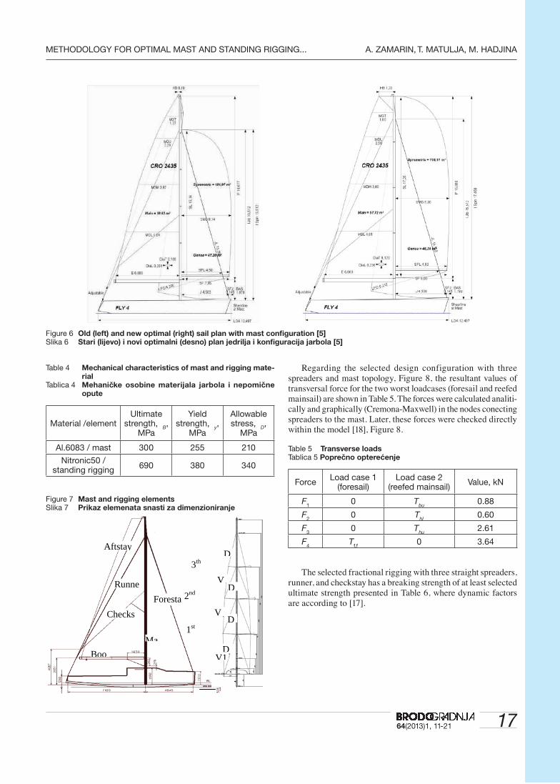
Design Alternative 18, as shown in Table 4, is the one where the mast material is of aluminium alloy (Al.6083), with three mast spreaders and the height of the main sail of 15.7 m, and with fi xed standing rigging from steel bars (Nitronix50). Illustration of the selected mast design is shown on right side of Figure 6. The considered yacht with such mast design con-fi guration obtained through the proposed phase is recognized as slower for approximately 4 seconds per nautical mile by ORCi theoretical background in comparison with the old de-sign, Figure 6 left. In practical race situations this represents a distance of 8 to 14 yacht lengths depending of the wind or yacht speed, which is obviously an important bonus regarding fi nal ranking. However, due to the crew and designer experience and knowledge it is expected that this yacht will actually be faster than before. It can be concluded that the goal of selecting the optimal mast confi guration regarding the particular ORCi handicap system is achieved.
Figure 5 Results of AHP/SA method Slika 5 Rezultati AHP/SA metode
For the selected mast design confi guration, structural analy-sis is conducted in order to obtain and verify the scantlings of structural elements, which are: mast, forestay, backstay, runner and shrouds, Figure 7. Modifi ed Skene method is used through the available Nordic Boat Standards [6], [17] and partially by use of ISO standard 12215-9 [7]. Allowable values of stresses are set to 90% of yield strength or 70% of ultimate strength, whatever is the lesser. Mechanical characteristics of the selected material, as well as allowable stresses are shown in Table 4.
1764(2013)1, 11-21
METHODOLOGY FOR OPTIMAL MAST AND STANDING RIGGING... A. ZAMARIN, T. MATULJA, M. HADJINA
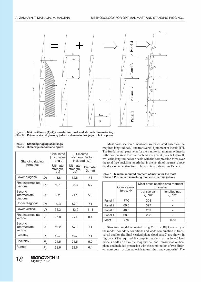
Regarding the selected design configuration with three spreaders and mast topology, Figure 8, the resultant values of transversal force for the two worst loadcases (foresail and reefed mainsail) are shown in Table 5. The forces were calculated analiti-cally and graphically (Cremona-Maxwell) in the nodes conecting spreaders to the mast. Later, these forces were checked directly within the model [18], Figure 8.
Table 5 Transverse loadsTablica 5 Poprečno opterećenje
ForceLoad case 1
(foresail)Load case 2
(reefed mainsail)Value, kN
F1
0 Tbu
0.88
F2
0 Thl
0.60
F3
0 Thu
2.61
F4
Tf,f
0 3.64
The selected fractional rigging with three straight spreaders, runner, and checkstay has a breaking strength of at least selected ultimate strength presented in Table 6, where dynamic factors are according to [17].
Figure 6 Old (left) and new optimal (right) sail plan with mast confi guration [5]Slika 6 Stari (lijevo) i novi optimalni (desno) plan jedrilja i konfi guracija jarbola [5]
DV1
Foresta
Aftstay
BooMa
V
V
D
D
D
Checks1st
2nd
3th
Runne
Table 4 Mechanical characteristics of mast and rigging mate-rial
Tablica 4 Mehaničke osobine materijala jarbola i nepomične opute
Material /elementUltimate
strength, B,
MPa
Yield strength,
y,
MPa
Allowable stress,
D,
MPa
Al.6083 / mast 300 255 210
Nitronic50 / standing rigging
690 380 340
Figure 7 Mast and rigging elementsSlika 7 Prikaz elemenata snasti za dimenzioniranje
18 64(2013)1, 11-21
A. ZAMARIN, T. MATULJA, M. HADJINA METHODOLOGY FOR OPTIMAL MAST AND STANDING RIGGING...
Table 6 Standing rigging scantlingsTablica 6 Dimenzije nepomične opute
Standing rigging(shrouds)
Calculated(max. value
1 and 2)
Selected(dynamic factor included [17])
Ultimate strength,
kN
Ultimate strength,
kN
Diameter D, mm
Lower diagonal D1 18.8 52.6 7.1
First intermediate diagonal D2 10.1 23.3 5.7
Second intermediate diagonal
D3 9.2 21.1 5.0
Upper diagonal D4 19.3 57.9 7.1
Lower vertical V1 35.3 112.9 11.1
First intermediate vertical V2 25.8 77.4 8.4
Second intermediate vertical
V3 19.2 57.6 7.1
Forestay Pfo
50.7 50.7 7.1
Backstay Pa
24.5 24.5 5.0
Runner Pa1
38.6 38.6 6.4
Mast cross section dimensions are calculated based on the required longitudinal I
y and transversal I
x moment of inertia [17].
The fundamental parameter for the transversal moment of inertia is the compression force on each mast segment (panel), Figure 8, while the longitudinal one deals with the compression force over the total free buckling length that is the height of the mast above the deck or superstructure. The results are shown in Table 7.
Table 7 Minimal required moment of inertia for the mastTablica 7 Proračun minimalnog momenta inercije jarbola
Compression force, kN
Mast cross section area moment of inertia
transversal, Ix, cm4
longitudinal, Iy, cm4
Panel 1 77.0 303 -
Panel 2 60.3 327 -
Panel 3 48.5 262 -
Panel 4 38.6 208 -
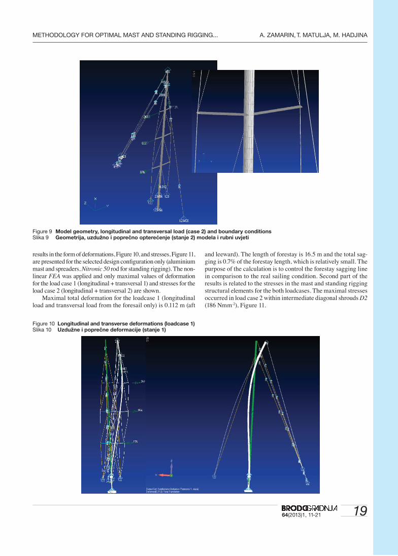
Mast 77.0 - 1465 Structural model is created using Nastran [18]. Geometry of
the model, boundary conditions and loads combination in trans-versal and longitudinal vertical plane (load case 2) are shown in Figure 9. FEA required 18 computer models that include 6 load models built up from the longitudinal and transversal vertical plane and included pretension with the combination of two differ-ent mast construction materials (aluminium and composite). The
+=
Pane
l 1
Pane
l 2
Pane
l 3
Pane
l 4
Figure 8 Main sail force (T2=T
m) transfer for mast and shrouds dimensioning
Slika 8 Prijenos sila od glavnog jedra za dimenzioniranje jarbola i pripona
1964(2013)1, 11-21
METHODOLOGY FOR OPTIMAL MAST AND STANDING RIGGING... A. ZAMARIN, T. MATULJA, M. HADJINA
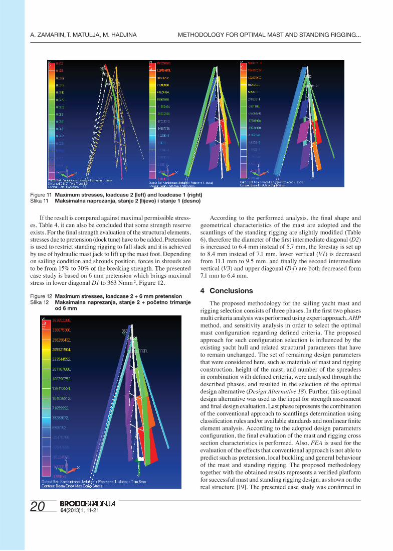
results in the form of deformations, Figure 10, and stresses, Figure 11, are presented for the selected design confi guration only (aluminium mast and spreaders, Nitronic 50 rod for standing rigging). The non-linear FEA was applied and only maximal values of deformation for the load case 1 (longitudinal + transversal 1) and stresses for the load case 2 (longitudinal + transversal 2) are shown.
Maximal total deformation for the loadcase 1 (longitudinal load and transversal load from the foresail only) is 0.112 m (aft
and leeward). The length of forestay is 16.5 m and the total sag-ging is 0.7% of the forestay length, which is relatively small. The purpose of the calculation is to control the forestay sagging line in comparison to the real sailing condition. Second part of the results is related to the stresses in the mast and standing rigging structural elements for the both loadcases. The maximal stresses occurred in load case 2 within intermediate diagonal shrouds D2 (186 Nmm-2), Figure 11.
Figure 9 Model geometry, longitudinal and transversal load (case 2) and boundary conditionsSlika 9 Geometrija, uzdužno i poprečno opterećenje (stanje 2) modela i rubni uvjeti
Figure 10 Longitudinal and transverse deformations (loadcase 1)Slika 10 Uzdužne i poprečne deformacije (stanje 1)
20 64(2013)1, 11-21
A. ZAMARIN, T. MATULJA, M. HADJINA METHODOLOGY FOR OPTIMAL MAST AND STANDING RIGGING...
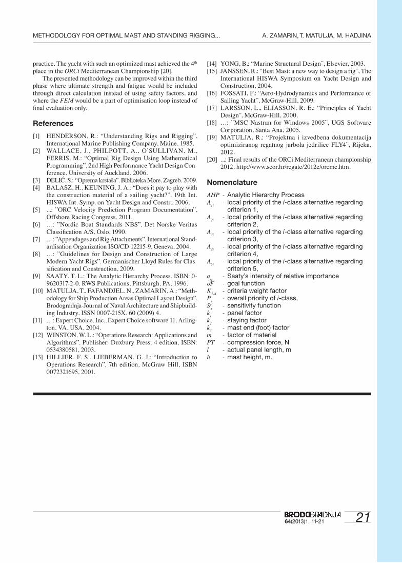
If the result is compared against maximal permissible stress-es, Table 4, it can also be concluded that some strength reserve exists. For the fi nal strength evaluation of the structural elements, stresses due to pretension (dock tune) have to be added. Pretension is used to restrict standing rigging to fall slack and it is achieved by use of hydraulic mast jack to lift up the mast foot. Depending on sailing condition and shrouds position, forces in shrouds are to be from 15% to 30% of the breaking strength. The presented case study is based on 6 mm pretension which brings maximal stress in lower diagonal D1 to 363 Nmm-2, Figure 12.
Figure 12 Maximum stresses, loadcase 2 + 6 mm pretensionSlika 12 Maksimalna naprezanja, stanje 2 + početno trimanje
od 6 mm
According to the performed analysis, the fi nal shape and geometrical characteristics of the mast are adopted and the scantlings of the standing rigging are slightly modifi ed (Table 6), therefore the diameter of the fi rst intermediate diagonal (D2) is increased to 6.4 mm instead of 5.7 mm, the forestay is set up to 8.4 mm instead of 7.1 mm, lower vertical (V1) is decreased from 11.1 mm to 9.5 mm, and fi nally the second intermediate vertical (V3) and upper diagonal (D4) are both decreased form 7.1 mm to 6.4 mm.
4 Conclusions
The proposed methodology for the sailing yacht mast and rigging selection consists of three phases. In the fi rst two phases multi criteria analysis was performed using expert approach, AHP method, and sensitivity analysis in order to select the optimal mast confi guration regarding defi ned criteria. The proposed approach for such confi guration selection is infl uenced by the existing yacht hull and related structural parameters that have to remain unchanged. The set of remaining design parameters that were considered here, such as materials of mast and rigging construction, height of the mast, and number of the spreaders in combination with defi ned criteria, were analysed through the described phases, and resulted in the selection of the optimal design alternative (Design Alternative 18). Further, this optimal design alternative was used as the input for strength assessment and fi nal design evaluation. Last phase represents the combination of the conventional approach to scantlings determination using classifi cation rules and/or available standards and nonlinear fi nite element analysis. According to the adopted design parameters confi guration, the fi nal evaluation of the mast and rigging cross section characteristics is performed. Also, FEA is used for the evaluation of the effects that conventional approach is not able to predict such as pretension, local buckling and general behaviour of the mast and standing rigging. The proposed methodology together with the obtained results represents a verifi ed platform for successful mast and standing rigging design, as shown on the real structure [19]. The presented case study was confi rmed in
Figure 11 Maximum stresses, loadcase 2 (left) and loadcase 1 (right)Slika 11 Maksimalna naprezanja, stanje 2 (lijevo) i stanje 1 (desno)
2164(2013)1, 11-21
METHODOLOGY FOR OPTIMAL MAST AND STANDING RIGGING... A. ZAMARIN, T. MATULJA, M. HADJINA
practice. The yacht with such an optimized mast achieved the 4th place in the ORCi Mediterranean Championship [20].
The presented methodology can be improved within the third phase where ultimate strength and fatigue would be included through direct calculation instead of using safety factors, and where the FEM would be a part of optimisation loop instead of fi nal evaluation only.
References
[1] HENDERSON, R.: “Understanding Rigs and Rigging”, International Marine Publishing Company, Maine, 1985.
[2] WALLACE, J., PHILPOTT, A., O’SULLIVAN, M., FERRIS, M.: “Optimal Rig Design Using Mathematical Programming”, 2nd High Performance Yacht Design Con-ference, University of Auckland, 2006.
[3] DELIĆ, S.: “Oprema krstaša”, Biblioteka More, Zagreb, 2009.[4] BALASZ, H., KEUNING, J. A.: “Does it pay to play with
the construction material of a sailing yacht?”, 19th Int. HISWA Int. Symp. on Yacht Design and Constr., 2006.
[5] ...: ”ORC Velocity Prediction Program Documentation”, Offshore Racing Congress, 2011.
[6] …: ”Nordic Boat Standards NBS”, Det Norske Veritas Classifi cation A/S, Oslo, 1990.
[7] …: ”Appendages and Rig Attachments”, International Stand-ardisation Organization ISO/CD 12215-9, Geneva, 2004.
[8] …: ”Guidelines for Design and Construction of Large Modern Yacht Rigs”, Germanischer Lloyd Rules for Clas-sifi cation and Construction, 2009.
[9] SAATY, T. L.: The Analytic Hierarchy Process, ISBN: 0-9620317-2-0. RWS Publications, Pittsburgh, PA, 1996.
[10] MATULJA, T., FAFANDJEL, N., ZAMARIN, A.: “Meth-odology for Ship Production Areas Optimal Layout Design”, Brodogradnja-Journal of Naval Architecture and Shipbuild-ing Industry, ISSN 0007-215X, 60 (2009) 4.
[11] …: Expert Choice, Inc., Expert Choice software 11, Arling-ton, VA, USA, 2004.
[12] WINSTON, W. L.: “Operations Research: Applications and Algorithms”, Publisher: Duxbury Press; 4 edition, ISBN: 0534380581, 2003.
[13] HILLIER, F. S., LIEBERMAN, G. J.: “Introduction to Operations Research”, 7th edition, McGraw Hill, ISBN 0072321695, 2001.
[14] YONG, B.: “Marine Structural Design”, Elsevier, 2003.[15] JANSSEN, R.: “Best Mast: a new way to design a rig”, The
International HISWA Symposium on Yacht Design and Construction, 2004.
[16] FOSSATI, F.: “Aero-Hydrodynamics and Performance of Sailing Yacht”, McGraw-Hill, 2009.
[17] LARSSON, L., ELIASSON, R. E.: “Principles of Yacht Design”, McGraw-Hill, 2000.
[18] …: ”MSC Nastran for Windows 2005”, UGS Software Corporation, Santa Ana, 2005.
[19] MATULJA, R.: “Projektna i izvedbena dokumentacija optimiziranog regatnog jarbola jedrilice FLY4”, Rijeka, 2012.
[20] ...: Final results of the ORCi Mediterranean championship 2012. http://www.scor.hr/regate/2012e/orcmc.htm.
Nomenclature
AHP - Analytic Hierarchy ProcessA
1i - local priority of the i-class alternative regarding
criterion 1,A
2i - local priority of the i-class alternative regarding
criterion 2,A
3i - local priority of the i-class alternative regarding
criterion 3,A
4i - local priority of the i-class alternative regarding
criterion 4,A
5i - local priority of the i-class alternative regarding
criterion 5,a
ij - Saaty’s intensity of relative importance
∂F - goal functionK
1-4 - criteria weight factor
Pi
- overall priority of i-class,SF
x - sensitivity function
k1
- panel factork
2 - staying factor
k3
- mast end (foot) factorm - factor of materialPT - compression force, Nl - actual panel length, mh - mast height, m.