Merging a DSP-Oriented Signal Integrity Technique and SW-Based Fault Handling Mechanisms to Ensure...
15
JOURNAL OF ELECTRONIC TESTING: Theory and Applications 20, 397–411, 2004 c 2004 Kluwer Academic Publishers. Manufactured in The United States. Merging a DSP-Oriented Signal Integrity Technique and SW-Based Fault Handling Mechanisms to Ensure Reliable DSP Systems FABIAN VARGAS, RUBEM D. FAGUNDES, DANIEL BARROS JR., DIOGO B. BRUM AND EDUARDO RHOD Electrical Engineering Department, Catholic University, PUCRS, Av. Ipiranga, 6681, 90619-900 Porto, Alegre, Brazil [email protected] Received September 9, 2002; Revised May 12, 2003 Editor: V. Champac Abstract. Hereafter, we present an approach aiming to improve the reliability of digital signal processing (DSP) systems operating in real noisy (electromagnetic interference—EMI) environments. The approach is based on the coupling of two techniques: the “DSP-oriented signal integrity improvement” technique deals with increasing the signal-to-noise ratio (SNR) and is essentially a modification of the classic Recovery Blocks Scheme. The second technique, named “SW-based fault handling” aims to detect in real-time data- and control-flow faults throughout modifications of the processor code. When compared to conventional approaches using Fast Fourier Transform (FFT) and Hamming Code, the primary benefit of such an approach is to improve system reliability by means of a considerably low complexity, reasonably low performance degradation and, when implemented in hardware, with reduced area overhead. Aiming to illustrate the proposed approach, we implemented a HW/SW prototype to operate as a speech recognition system (SRS). This prototype was tested under a home-tailored EMI environment according to the IEC 61000-4-29 International Standard Normative. The obtained results indicate that the proposed approach can effectively improve the reliability of DSP systems operating in real noise (EMI) environments. Keywords: digital signal processing (DSP) systems, electromagnetic interference (EMI), on-line testing, speech recognition system (SRS), noise immunity 1. Introduction The electromagnetic EM environment in which elec- tronic systems have to operate is becoming increasingly hostile while dependence on electronics is widespread and increasing. The need for assurance that applica- tion upsets due to the EM environment will not occur is fundamental to acceptance of systems as fit for pur- pose. In order to solve such problems, design features to impart EM hardness (i.e., Design for Electromagnetic Immunity—DEMI) at the IC-level are beginning to be implemented, but at very high cost in terms of system performance, power consumption, and implementation complexity [14, 21, 29]. It is well known that the CMOS technology roadmap leads to the reduction of supply voltages (at least for the core part). This fact raises the hope for less electromag- netic emission (conducted and radiated). However, this benefit is immediately compensated by a drastically increased number of simultaneously switching tran- sistors per die, combined with faster switching edges due to increasing clock rates [21]. Thus, increasing the total RF noise that can affect embedded functional blocks inside the die itself, as well as affect other dies
-
Upload
independent -
Category
Documents
-
view
2 -
download
0
Transcript of Merging a DSP-Oriented Signal Integrity Technique and SW-Based Fault Handling Mechanisms to Ensure...
JOURNAL OF ELECTRONIC TESTING: Theory and Applications 20, 397–411, 2004c© 2004 Kluwer Academic Publishers. Manufactured in The United States.
Merging a DSP-Oriented Signal Integrity Technique and SW-Based FaultHandling Mechanisms to Ensure Reliable DSP Systems
FABIAN VARGAS, RUBEM D. FAGUNDES, DANIEL BARROS JR., DIOGO B. BRUMAND EDUARDO RHOD
Electrical Engineering Department, Catholic University, PUCRS, Av. Ipiranga, 6681,90619-900 Porto, Alegre, Brazil
Received September 9, 2002; Revised May 12, 2003
Editor: V. Champac
Abstract. Hereafter, we present an approach aiming to improve the reliability of digital signal processing (DSP)systems operating in real noisy (electromagnetic interference—EMI) environments. The approach is based onthe coupling of two techniques: the “DSP-oriented signal integrity improvement” technique deals with increasingthe signal-to-noise ratio (SNR) and is essentially a modification of the classic Recovery Blocks Scheme. Thesecond technique, named “SW-based fault handling” aims to detect in real-time data- and control-flow faultsthroughout modifications of the processor code. When compared to conventional approaches using Fast FourierTransform (FFT) and Hamming Code, the primary benefit of such an approach is to improve system reliabilityby means of a considerably low complexity, reasonably low performance degradation and, when implemented inhardware, with reduced area overhead. Aiming to illustrate the proposed approach, we implemented a HW/SWprototype to operate as a speech recognition system (SRS). This prototype was tested under a home-tailored EMIenvironment according to the IEC 61000-4-29 International Standard Normative. The obtained results indicatethat the proposed approach can effectively improve the reliability of DSP systems operating in real noise (EMI)environments.
Keywords: digital signal processing (DSP) systems, electromagnetic interference (EMI), on-line testing, speechrecognition system (SRS), noise immunity
1. Introduction
The electromagnetic EM environment in which elec-tronic systems have to operate is becoming increasinglyhostile while dependence on electronics is widespreadand increasing. The need for assurance that applica-tion upsets due to the EM environment will not occuris fundamental to acceptance of systems as fit for pur-pose. In order to solve such problems, design features toimpart EM hardness (i.e., Design for ElectromagneticImmunity—DEMI) at the IC-level are beginning to beimplemented, but at very high cost in terms of system
performance, power consumption, and implementationcomplexity [14, 21, 29].
It is well known that the CMOS technology roadmapleads to the reduction of supply voltages (at least for thecore part). This fact raises the hope for less electromag-netic emission (conducted and radiated). However, thisbenefit is immediately compensated by a drasticallyincreased number of simultaneously switching tran-sistors per die, combined with faster switching edgesdue to increasing clock rates [21]. Thus, increasingthe total RF noise that can affect embedded functionalblocks inside the die itself, as well as affect other dies

398 Vargas et al.
or ICs placed nearby it. For instance, it is well knownthat dynamic switching currents in the supply lines onthe silicon die are one of the main sources of radi-ated electromagnetic emission which causes the powerlines to behave as antennas and to radiate undesirednoise. This RF signal induces embedded (more sensi-tive) functional blocks in the die to suffer from spuriouscurrent switching spikes [7]. In addition to affect thefunctional blocks, these current spikes are conductedin the form of noise outside the IC through the powersupply and/or data lines and may affect several othercomponents mounted on the application board [22].
Most of the solutions found in the literature aiming tominimize electromagnetic emissions are design-basedpropositions [21]. In general, they intend to reduce thedynamic switching currents or optimize distribution ofswitching currents over time. As examples, block de-coupling capacitors and improved pad-drivers designcontribute to the first, while clock concepts with inten-tional non-zero skew to the second. Note that sinceI/O signals are important contributors to undesiredRF emission in electronic systems, the design of paddrivers as weak as possible could contribute to mini-mize RF emission. However, note also that this solutionleads to a more sensitive IC to noise as well as may ex-pose it to delay faults since transistors become slowerwith higher temperatures.
Considering the design of ICs with non-zero skewclock signals, this measure effectively reduces electro-magnetic emission. However, clock smearing by defin-ing rising and falling edges to occur at different timesalong with the supply lines plane goes against tech-nology scaling, since a “good” design mandates theimplementation of ICs with as perfect as possible syn-chronized (zero-skew) control signals distributed allover the IC functional blocks. Note also that the zero-skew trend is naturally supported by today’s designtools, but if chip designers should take advantage fromimplementing the clock smearing concept for the sakeof reduced RF emission, he/she should perform thisclock distribution modification by him/herself, sincetoday’s tools do not support directly non-zero clocksignal design.
Considering the above introduced, this work pro-poses an approach aiming to improve the reliability ofdigital signal processing (DSP) systems operating inreal noisy (electromagnetic interference—EMI) envi-ronments. The approach is the coupling of two tech-niques: the DSP-oriented signal integrity improvementtechnique [27] deals with increasing the signal-to-noise
ratio (SNR) and is essentially a modification of the clas-sic Recovery Blocks Scheme [15]. On the other hand,the SW-based fault handling technique [24] aims to de-tect in real-time data- and control-flow faults through-out modifications of the processor C-code. When com-pared to conventional approaches using Fast FourierTransform (FFT) and Hamming Code, the primary ben-efit of such an approach is to improve system reliabilityby means of a considerably low complexity, reason-ably low performance degradation and reduced areaoverhead required for implementation.
Aiming to illustrate the proposed approach, we im-plemented a HW/SW prototype to operate as a speechrecognition system (SRS). This prototype was testedunder a home-tailored EMI environment according tothe IEC 61000-4-29 International Standard Normative[8]. The obtained results indicate that the proposed ap-proach can effectively improve the reliability of DSPsystems operating in real noise (EMI) environments.
The reminder of the paper is divided as follows:Section 2 presents the very basic concepts involvingspeech recognition systems. The control and data flows,by means of general block diagrams, are briefly intro-duced to readers not familiar with such type of DSP sys-tems. Section 3 details the proposed DSP-oriented sig-nal integrity improvement technique by explaining howit “reconstructs” noisy signals. Section 4 presents theSW-based fault detection mechanisms implemented atthe processor C-code level. Section 5 is devoted to ex-perimental results: a computation example is presentedto illustrate the effectiveness of the proposed approachdescribed in Sections 3 and 4. To conclude, Section 6presents the final considerations and future work.
2. Preliminary Considerations on the GeneralStructure of Speech Recognition Systems
A speech recognition system (SRS) is basically a pat-tern recognition system dedicated to detect speech [3].In other words, to identify language words into a soundsignal achieved as input from the environment. Fig.1shows the main steps performed by a front-end speechrecognition system [5, 6, 9, 16, 17].
In the Signal Analysis step, a speech sampling willbe made with an A/D converter. Those samples are pro-cessed in order to extract some relevant features fromspeech signal input. This step is responsible for signalhandling, by converting the analog signal sampling,into a digital representation. The last task performed

Merging a DSP-Oriented Signal Integrity Technique and SW-Based Fault Handling Mechanisms 399
Fig. 1. General block diagram of speech recognition systems [5,6, 9, 17, 26].
in this step is the vector quantization, when the speechsignal is then replaced by a proper sequence of label-codes (this is the input for the next step of the SRSsystem, which is responsible for pattern matching).
The Pattern Matching & the Decision Logic stepsare the “identification” steps, where the words spelledin the speech signal are recognized by generating asequence of text words. The sequence of label-codesis evaluated using Hidden Markov Models (HMM),which as the acoustic reference pattern, plays the mainrole in the recognition process [19, 25]. At the endof this process, the Decision Logic Block comparesthe final probability values from the HMM blocksagainst a reference (threshold) value and selects the onewith higher score (i.e., higher probability) of being thesearched word. Then, recognizing the word. The Pat-tern Matching & Decision Logic steps have been imple-mented by the Viterbi algorithm [17, 18, 25, 28] to per-form the evaluation of the code-label sequence againstthe HMM structures. For detailed information aboutthe general structure of speech recognition systems,interested readers may address references [6, 17, 27].
3. The DSP-Oriented Signal Integrity(DSP-SI) Technique
Although convolutional codes, first introduced by Elias[28], have been applied over the past decades to in-crease the efficiency of numerous communication sys-tems where they invariably improve the quality of thereceived information, there remains to date a lack ofreliability when such an information is used to repre-sent more complex data structures (e.g., speech, im-age). To overcome this problem, we are proposing anew approach to minimize (and if possible, eliminate)the noise associated with data in convolutional-codedigital signal processing systems.
Even though the proposed DSP-oriented signal in-tegrity technique can be used to improve signal quality
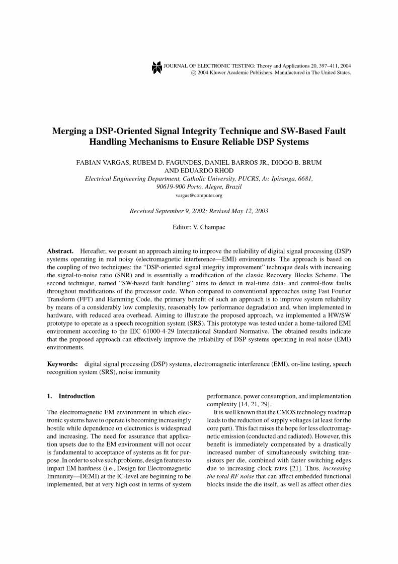
for any convolutional-code handling system [27], in or-der to facilitate the introduction of the technique and thebasic ideas, we illustrate this proposition by focusingspecifically on a case study devoted to speech recogni-tion as a typical application example. In these applica-tions, voice-oriented systems are frequently struggledby noise like electromagnetic interference, or just back-ground noise. As consequence, the information (i.e.,the speech) is partially (or even totally) buried by noise.Thus, reducing the reliability of the incoming signal.Therefore, in order to overcome this problem the pro-posed DSP-oriented signal integrity improvement tech-nique aims to allow a more reliable speech recognitionprocess. The basic idea behind the proposed techniqueis to perform the reconstruction of the incoming sig-nal every time the code labels sequence on the processof recognition does not respect a fundamental rule ofquality [27]. The algorithm used is based on HiddenMarkov Models (HMM) and performs on-line testingby means of a modified version of the classic RecoveryBlocks technique [15]. Fig. 2 detailsthe main blocks ofthe proposed approach.
Basically, the approach works as follows: the incom-ing signal is analyzed by the Viterbi Algorithm whichwas implemented by means of the Hidden MarkovModels (HMM), as described in Section 2. Note thatthe input signal (indicated by “∗” in Fig. 2) is the obser-vations sequence, i.e., digital code labels representingspeech. Therefore, in the occurrence of an incomingsignal, Subsystem-I begins the process of recognitionof the arriving observation codes. Note that the SRSmust be previously trained to do this work, and thatthe number of words that can be recognized is equalto the number of HMM Blocks inside Subsystems I orII. Each one of these HMM Blocks is used to modela single word. (For details about the process of mod-eling words and training the HMM Blocks, interestedreaders can address [4, 16, 18, 19].)
The whole approach is controlled by the Viterbi Al-gorithm Controller (“VAC Block”, in Fig. 2), whichsupervises the processes running on Subsystem-I andon the Code Labels Sequence Simulator (CLSS). Whilethe goal of the “HMM” Blocks in Subsystem-I is tocompute the HMM probability scores for each of theincoming observations (∗), the goal of the VAC Blockis to check if the code labels sequence respects a funda-mental rule [27] and if it is not the case, the VAC Blockswitches from Subsystem-I to CLSS. The VAC Blockremains switched on the CLSS during a predefined pe-riod of time, and then, bounces back to the original
400 Vargas et al.
Fig. 2. The proposed approach: (a) General Block Diagram; and (b) More details for a 3-word recognition example.
incoming signal, i.e., to Subsystem-I. This process isdynamically performed every time the code labels se-quence forming the original noisy speech signal doesnot respect a fundamental rule of quality.
For comparison purpose, the proposed VAC Blockperforms the Acceptance Tests that are commonly car-ried out in Recovery Blocks schemes [15]. Having thiscomparison in mind, Fig. 2(a) shows the general blockdiagram of the proposed approach, which executes thefollowing algorithm:
Ensure TBy PElse Q
Else Error
where: T: Word recognition process; P: Primary Block(STEP-I); Q: Alternate Block (STEP-II); Error: Word
recognition failure (insufficient signal-to-noise ratio,preventing the word to be correctly recognized).
For detailed information about the reconstructiontechnique of the noisy original signal and the pseu-dorandom generation process of observation sequencesegments, interested readers may address [27].
4. The SW-Based Fault Handling Technique
The basic idea behind this approach is to apply the SW-based fault detection mechanisms described hereafterinto the application code, in particular into the partof the application code that implements the DSP-SItechnique described in the previous section.
A dedicated reader can find in the literature sev-eral other SW-based fault detection techniques pre-senting different degrees of success, in particular

Merging a DSP-Oriented Signal Integrity Technique and SW-Based Fault Handling Mechanisms 401
those techniques handling control-flow faults detec-tion. Some representative examples are [2, 11–13].Note also that the proposed technique is the only one,as far as we have knowledge, that has been com-pletely automated (it was implemented a compiler tool[20, 30, 31] which automatically modifies the proces-sor C-code into a fault-tolerant one according to thedefinitions presented in the following). Additionally,this is a purely software-implemented approach (i.e.,completely hardware-independent), thus being easilymapped into commercial-off-the-shelf (COTS) micro-processors [24].
The technique is divided into two steps, accordingto the type of information to be protected:
(a) Faults affecting data: we implemented the tech-nique proposed by Matteo et al. [20], which is basedon the following three basic rules:
• Rule #1: every variable x must be duplicated: let x1and x2 be the names of the two copies;
• Rule #2: every write operation performed on x mustbe performed on x1 and x2;
• Rule #3: after each read operation on x , the twocopies x1 and x2 must be checked for consistency,and an error detection procedure should be activatedif an inconsistency is detected.
The above rules mean that any variable v must besplit in two copies v0 and v1 and that these copiesshould always store the same value. A consistencycheck on v0 and v1 must be performed each time thevariable is read. The check must be performed immedi-ately after the read operation in order to block the faulteffect propagation. Also, each instruction that writesvariable v must also be duplicated in order to updatethe two copies of the variable.
Additionally, note that the variables should also bechecked when they appear in any expression used as acondition for branches or loops, thus allowing detectionof errors that corrupt the correct control flow executionof a program.
Every fault that occurs in any variable during theprogram execution can be detected as soon as the vari-able is the source operand of an instruction, i.e., whenthe variable is read. Thus resulting in minimum errorlatency, which is approximately equal to the distancebetween the fault occurrence and the first read opera-tion. In this technique, errors affecting variables aftertheir last usage are not detected. Fig. 3illustrates twosimple examples, by showing the code modification
Fig. 3. Code modification for errors affecting data.
for an assignment operation and for a sum operationinvolving three variables a, b, and c.
The parameters passed to a procedure, as well asthe returned values should be considered as variables.Therefore, the rules defined previously should be ex-tended as follows:
• Every procedure parameter is duplicated;• Each time the procedure reads a parameter, it checks
the two copies for consistency;• The return value is also duplicated (in C, this means
that the addresses of the two copies are passed asparameters to the called procedure).
Fig. 4 depictsan example of application of Rules #1to #3 to the parameters of a procedure.
(b) Faults affecting the control flow: errors affectingcontrol flow can be divided into two categories, depend-ing on the way they transform the statement whose codeis modified [20]:
• Type Error-A: errors changing the control flow by af-fecting data in arithmetic expressions, computations,and assignments, for instance. As example, consider
Fig. 4. Code transformation for errors affecting procedure para-meters.
402 Vargas et al.
an error transforming an add operation into a jumpone.
• Type Error-B: errors changing the control flow byaffecting data in tests, loops, procedure calls, andreturns, for instance. As example, consider an errortransforming a data i into an i ′ (in the assumed exam-ple, i is compared to j in a conditional branch-takendecision instruction).
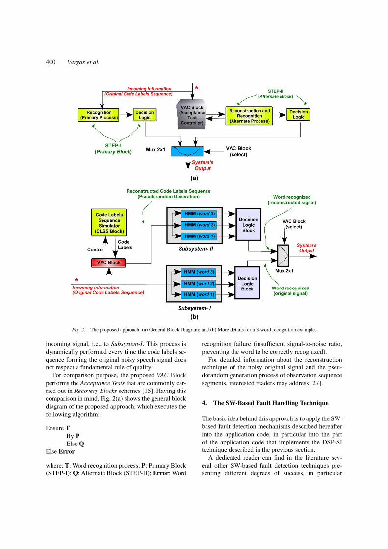
The solution for detecting errors of type Error-A isbased on tracking the execution flow by trying to detectdifferences with respect to the correct behavior. Thistask is performed by first identifying all the basic blockscomposing the code. A basic code is a sequence ofstatements, which is always indivisibly executed (i.e.,they are branch-free). The following rules are then in-troduced, in order to check whether all the statementsin every basic block are executed in sequence:
• Rule #4: an integer value ki is associated with everybasic block i in the code;
• Rule #5: a global execution check flag (ecf ) variableis defined. A statement assigning to ecf the value ofki is introduced at the very beginning of every basicblock i . A test on the value of ecf is also performedat the end of the basic block.
The aim of the above rules is to check whether anyerror happened, whose effect is to modify the correctexecution flow, and to introduce a jump to an incorrecttarget address. An example of this situation is an errormodifying the field containing the target address in ajump instruction. As a further example, consider an er-ror that changes an ALU instruction (e.g., an add) into abranch one: if the instruction format includes an imme-diate field, this may possibly be interpreted as a targetaddress. Unfortunately, note also that the above ruleshave an incomplete detection capability since there aresome fault types that cannot be detected (e.g., any er-ror producing a jump to the first assembly instructionof a basic block: thus assigning to ecf the value cor-responding to the block; or even any erroneous jumpinto the same basic block). Fig. 5 providesan exampleof application of Rules #4 and #5.
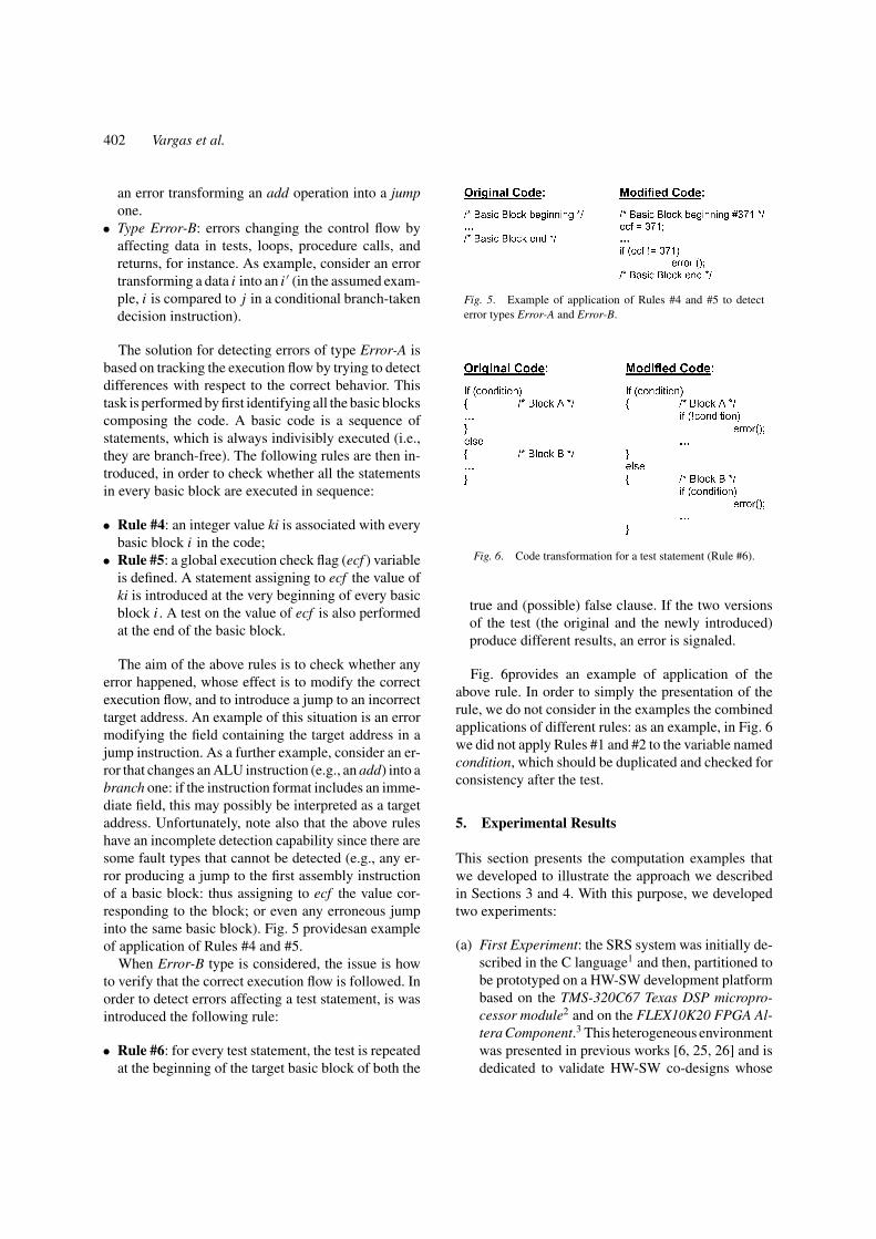
When Error-B type is considered, the issue is howto verify that the correct execution flow is followed. Inorder to detect errors affecting a test statement, is wasintroduced the following rule:
• Rule #6: for every test statement, the test is repeatedat the beginning of the target basic block of both the
Fig. 5. Example of application of Rules #4 and #5 to detecterror types Error-A and Error-B.
Fig. 6. Code transformation for a test statement (Rule #6).
true and (possible) false clause. If the two versionsof the test (the original and the newly introduced)produce different results, an error is signaled.
Fig. 6provides an example of application of theabove rule. In order to simply the presentation of therule, we do not consider in the examples the combinedapplications of different rules: as an example, in Fig. 6we did not apply Rules #1 and #2 to the variable namedcondition, which should be duplicated and checked forconsistency after the test.
5. Experimental Results
This section presents the computation examples thatwe developed to illustrate the approach we describedin Sections 3 and 4. With this purpose, we developedtwo experiments:
(a) First Experiment: the SRS system was initially de-scribed in the C language1 and then, partitioned tobe prototyped on a HW-SW development platformbased on the TMS-320C67 Texas DSP micropro-cessor module2 and on the FLEX10K20 FPGA Al-tera Component.3 This heterogeneous environmentwas presented in previous works [6, 25, 26] and isdedicated to validate HW-SW co-designs whose
Merging a DSP-Oriented Signal Integrity Technique and SW-Based Fault Handling Mechanisms 403
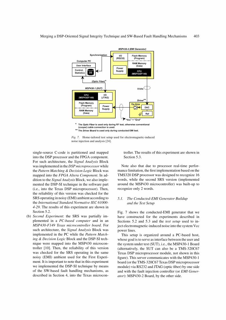
Fig. 7. Home-tailored test setup used for electromagnetic-inducednoise injection and analysis [24].
single-source C-code is partitioned and mappedinto the DSP processor and the FPGA component.For such architecture, the Signal Analysis Blockwas implemented in the DSP microprocessor whilethe Pattern Matching & Decision Logic Block wasmapped into the FPGA Altera Component. In ad-dition to the Signal Analysis Block, we also imple-mented the DSP-SI technique in the software part(i.e., into the Texas DSP microprocessor). Then,the reliability of this version was checked for theSRS operating in noisy (EMI) ambient according tothe International Standard Normative IEC 61000-4-29. The results of this experiment are shown inSection 5.2.
(b) Second Experiment: the SRS was partially im-plemented in a PC-based computer and in anMSP430-F149 Texas microcontroller board. Forsuch architecture, the Signal Analysis Block wasimplemented in the PC while the Pattern Match-ing & Decision Logic Block and the DSP-SI tech-nique were mapped into the MSP430 microcon-troller [10]. Then, the reliability of this versionwas checked for the SRS operating in the samenoisy (EMI) ambient used for the First Experi-ment. It is important to note that in this experimentwe implemented the DSP-SI technique by meansof the SW-based fault handling mechanisms, asdescribed in Section 4, into the Texas microcon-
troller. The results of this experiment are shown inSection 5.3.
Note also that due to processor real-time perfor-mance limitation, the first implementation based on theTMS320 DSP processor was designed to recognize 16words, while the second SRS version (implementedaround the MSP430 microcontroller) was built-up torecognize only 2 words.
5.1. The Conducted-EMI Generator Buildupand the Test Setup
Fig. 7 shows the conducted-EMI generator that wehave constructed for the experiments described inSections 5.2 and 5.3 and the test setup used to in-ject electromagnetic-induced noise into the system Vccpower lines.
This setup is organized around a PC-based host,whose goal is to serve as interface between the user andthe system under test (SUT), i.e., the MSP430-1 Board(alternatively, the SUT can also be a TMS-320C67Texas DSP microprocessor module, not shown in thisfigure). This server communicates with the MSP430-1board (or the TMS-320C67 Texas DSP microprocessormodule) via RS232 and JTAG (optic fiber) by one sideand with the fault injection controller (or EMI Gener-ator): MSP430-2 Board, by the other side.
404 Vargas et al.
The SUT in Fig. 7 is the MSP430-1 Board, which isbased on a Texas Microcontroller MSP430F149 [10].This component contains 60 KB flash memory to storecontrol program and 2 KB of RAM to store data aswell as control state variables. This RAM also servesas stack area for the control part. Similarly, the EMIGenerator (MSP430-2 Board) is also based on the samemicrocontroller device.
As can be seen in Fig. 7, the program stored inthe flash memory of the EMI Generator controls theDriver Board by means of sending control signals tothe digital-to-analog converter (DAC). Based on a ref-erence voltage (REF), this converter translates the dig-ital command into an analog signal, which controls theoperational amplifier (OpAmp, in the Driver Board).Then, the OpAmp output generates the correspondinganalog “noisy Vcc signal” which is injected in the formof voltage dips into the system under test (i.e., into theMSP430F149 microcontroller or TMS-320C67 pro-cessor Vcc power pins).
Note also that the International Standard IEC61.000-4-29 Normative oriented the noise modelingand injection procedure executed by the EMI Gener-ator (MSP430-2 Board). This normative rules testingproceedings for voltage dips, voltage interruptions, andvoltage variations on the DC-input power port of elec-
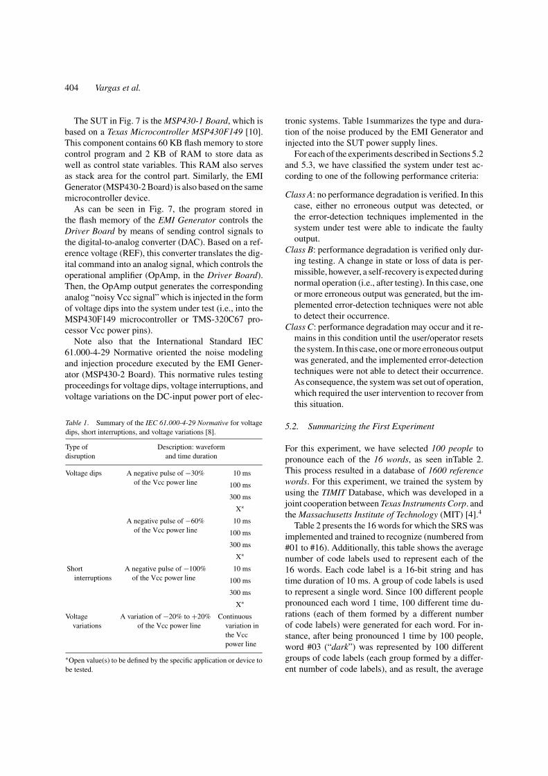
Table 1. Summary of the IEC 61.000-4-29 Normative for voltagedips, short interruptions, and voltage variations [8].
Type of Description: waveformdisruption and time duration
Voltage dips A negative pulse of −30%of the Vcc power line
10 ms
100 ms
300 ms
X∗
A negative pulse of −60%of the Vcc power line
10 ms
100 ms
300 ms
X∗
Shortinterruptions
A negative pulse of −100%of the Vcc power line
10 ms
100 ms
300 ms
X∗
Voltage A variation of −20% to +20% Continuousvariations of the Vcc power line variation in
the Vccpower line
∗Open value(s) to be defined by the specific application or device tobe tested.
tronic systems. Table 1summarizes the type and dura-tion of the noise produced by the EMI Generator andinjected into the SUT power supply lines.
For each of the experiments described in Sections 5.2and 5.3, we have classified the system under test ac-cording to one of the following performance criteria:
Class A: no performance degradation is verified. In thiscase, either no erroneous output was detected, orthe error-detection techniques implemented in thesystem under test were able to indicate the faultyoutput.
Class B: performance degradation is verified only dur-ing testing. A change in state or loss of data is per-missible, however, a self-recovery is expected duringnormal operation (i.e., after testing). In this case, oneor more erroneous output was generated, but the im-plemented error-detection techniques were not ableto detect their occurrence.
Class C: performance degradation may occur and it re-mains in this condition until the user/operator resetsthe system. In this case, one or more erroneous outputwas generated, and the implemented error-detectiontechniques were not able to detect their occurrence.As consequence, the system was set out of operation,which required the user intervention to recover fromthis situation.
5.2. Summarizing the First Experiment
For this experiment, we have selected 100 people topronounce each of the 16 words, as seen inTable 2.This process resulted in a database of 1600 referencewords. For this experiment, we trained the system byusing the TIMIT Database, which was developed in ajoint cooperation between Texas Instruments Corp. andthe Massachusetts Institute of Technology (MIT) [4].4
Table 2 presents the 16 words for which the SRS wasimplemented and trained to recognize (numbered from#01 to #16). Additionally, this table shows the averagenumber of code labels used to represent each of the16 words. Each code label is a 16-bit string and hastime duration of 10 ms. A group of code labels is usedto represent a single word. Since 100 different peoplepronounced each word 1 time, 100 different time du-rations (each of them formed by a different numberof code labels) were generated for each word. For in-stance, after being pronounced 1 time by 100 people,word #03 (“dark”) was represented by 100 differentgroups of code labels (each group formed by a differ-ent number of code labels), and as result, the average
Merging a DSP-Oriented Signal Integrity Technique and SW-Based Fault Handling Mechanisms 405
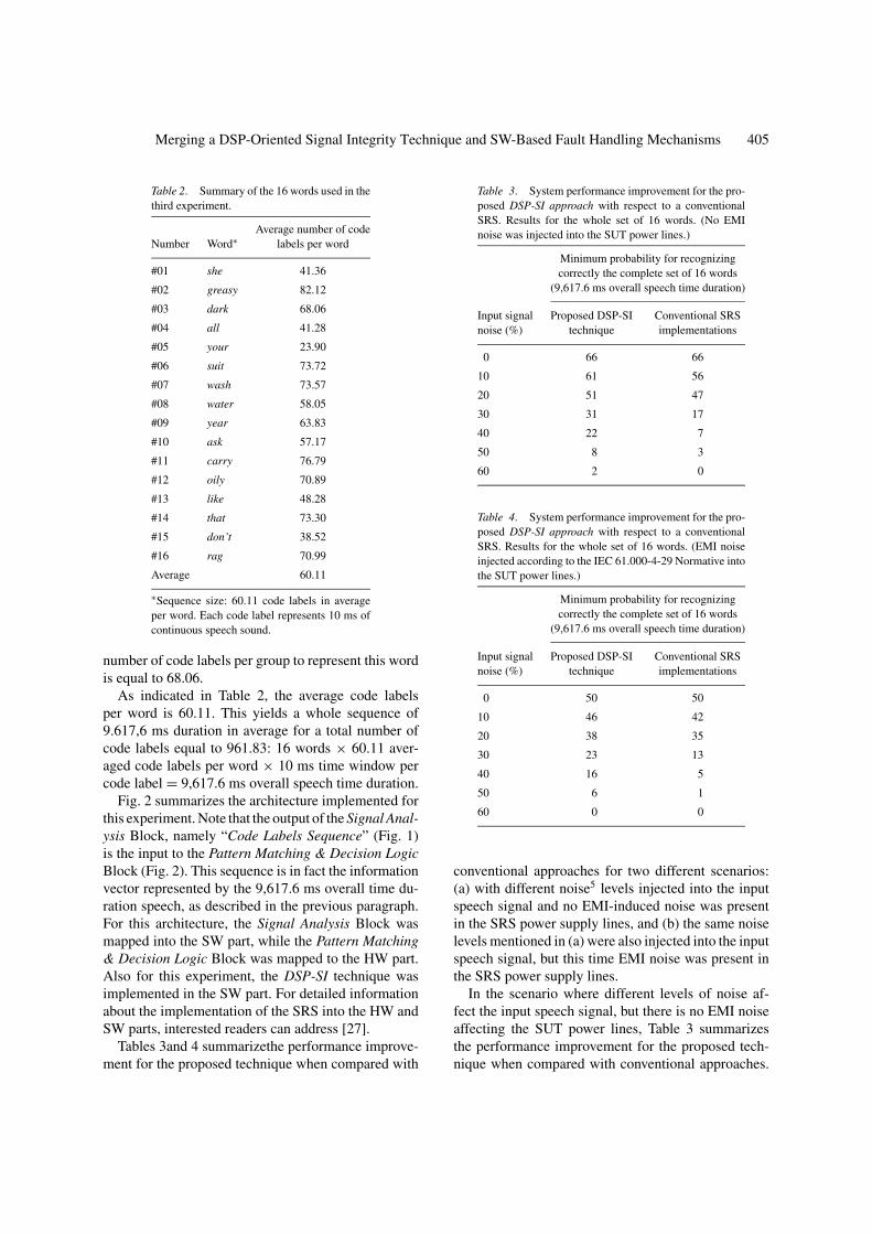
Table 2. Summary of the 16 words used in thethird experiment.
Average number of codeNumber Word∗ labels per word
#01 she 41.36
#02 greasy 82.12
#03 dark 68.06
#04 all 41.28
#05 your 23.90
#06 suit 73.72
#07 wash 73.57
#08 water 58.05
#09 year 63.83
#10 ask 57.17
#11 carry 76.79
#12 oily 70.89
#13 like 48.28
#14 that 73.30
#15 don’t 38.52
#16 rag 70.99
Average 60.11
∗Sequence size: 60.11 code labels in averageper word. Each code label represents 10 ms ofcontinuous speech sound.
number of code labels per group to represent this wordis equal to 68.06.
As indicated in Table 2, the average code labelsper word is 60.11. This yields a whole sequence of9.617,6 ms duration in average for a total number ofcode labels equal to 961.83: 16 words × 60.11 aver-aged code labels per word × 10 ms time window percode label = 9,617.6 ms overall speech time duration.
Fig. 2 summarizes the architecture implemented forthis experiment. Note that the output of the Signal Anal-ysis Block, namely “Code Labels Sequence” (Fig. 1)is the input to the Pattern Matching & Decision LogicBlock (Fig. 2). This sequence is in fact the informationvector represented by the 9,617.6 ms overall time du-ration speech, as described in the previous paragraph.For this architecture, the Signal Analysis Block wasmapped into the SW part, while the Pattern Matching& Decision Logic Block was mapped to the HW part.Also for this experiment, the DSP-SI technique wasimplemented in the SW part. For detailed informationabout the implementation of the SRS into the HW andSW parts, interested readers can address [27].
Tables 3and 4 summarizethe performance improve-ment for the proposed technique when compared with
Table 3. System performance improvement for the pro-posed DSP-SI approach with respect to a conventionalSRS. Results for the whole set of 16 words. (No EMInoise was injected into the SUT power lines.)
Minimum probability for recognizingcorrectly the complete set of 16 words
(9,617.6 ms overall speech time duration)
Input signal Proposed DSP-SI Conventional SRSnoise (%) technique implementations
0 66 66
10 61 56
20 51 47
30 31 17
40 22 7
50 8 3
60 2 0
Table 4. System performance improvement for the pro-posed DSP-SI approach with respect to a conventionalSRS. Results for the whole set of 16 words. (EMI noiseinjected according to the IEC 61.000-4-29 Normative intothe SUT power lines.)
Minimum probability for recognizingcorrectly the complete set of 16 words
(9,617.6 ms overall speech time duration)
Input signal Proposed DSP-SI Conventional SRSnoise (%) technique implementations
0 50 50
10 46 42
20 38 35
30 23 13
40 16 5
50 6 1
60 0 0
conventional approaches for two different scenarios:(a) with different noise5 levels injected into the inputspeech signal and no EMI-induced noise was presentin the SRS power supply lines, and (b) the same noiselevels mentioned in (a) were also injected into the inputspeech signal, but this time EMI noise was present inthe SRS power supply lines.
In the scenario where different levels of noise af-fect the input speech signal, but there is no EMI noiseaffecting the SUT power lines, Table 3 summarizesthe performance improvement for the proposed tech-nique when compared with conventional approaches.
406 Vargas et al.
Therefore, this table shows the minimum probabilitiesfor the system to recognize correctly the set of 16 wordsfor different noise levels present in the speech signal.By reading Table 3, for instance, assume that for aninput signal noise level of 20%, the minimum proba-bility for the SRS based on the proposed technique torecognize correctly the whole set of 16 words is 51%(such a lowest probability was obtained for word #6:suit). In other words, for every 100 times the set of 16words was pronounced, the system recognized 49 timesat least one word erroneously. Note that for the samenoise level, on the other hand, the minimum probabilityfor an SRS based on conventional approaches to rec-ognize correctly the same set of 16 words is reduced to47% (the word with the lowest probability, in this case,is #4: all) [27].
Finally, note that when no noise is present in theinput speech signal (0%), the performance improve-ment provided by the proposed technique is null. Thisis explained because since there is no noise, the re-construction procedure is not performed by the DSP-SI approach. This implies that the SRS output is afunction of the original signal only. Thus, provid-ing exactly the same confidence as the conventionalapproach.
For Table 4, the scenario is completely different fromthe one presented in Table 3: now, in addition to dif-ferent levels of noise affecting the input speech signal(from 10 to 60%), EMI noise was also injected accord-ing to the IEC 61.000-4-29 Normative into the SUTpower lines. For this experiment, EMI noise was mod-eled as voltage dips of 100 ms duration, with −30%of the Vcc power line amplitude, and 30us for rise andfall times. Later, noise was also modeled in the form ofshort interruptions and voltage variations. In the firstcase (short interruptions), the SUT based on the TMS-320C67 Texas DSP microprocessor module and on theFLEX10K20 FPGA Altera Component crashed beforeit delivered its output, i.e., the system was completelyreset every time short interruptions (of 10ms minimumduration, with 30us for rise and fall times) were appliedto its Vcc power lines. In the second case (voltage vari-ations), no functional disruption was observed whenthe SUT was disturbed by voltage variations of −20%to +20% of the Vcc power line.
5.3. Summarizing the Second Experiment
For the experiment presented in this section, we havemodified the C-code describing the DSP-SI technique,
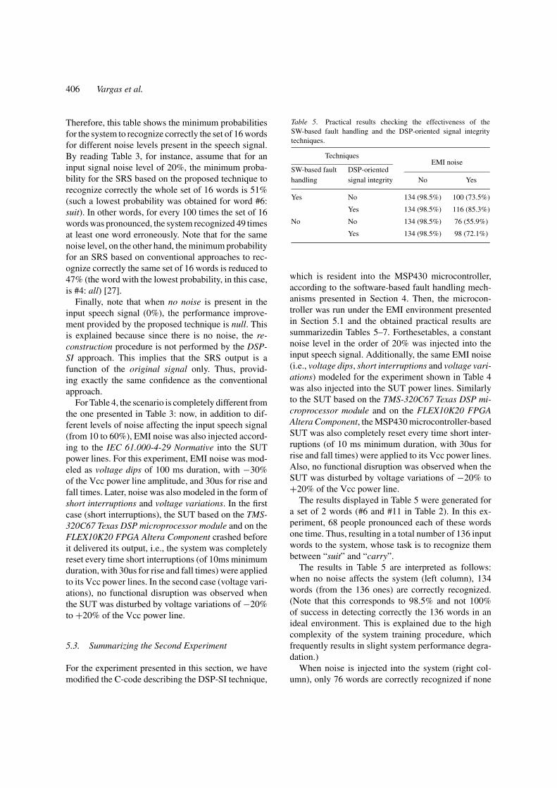
Table 5. Practical results checking the effectiveness of theSW-based fault handling and the DSP-oriented signal integritytechniques.
TechniquesEMI noise
SW-based fault DSP-orientedhandling signal integrity No Yes
Yes No 134 (98.5%) 100 (73.5%)
Yes 134 (98.5%) 116 (85.3%)
No No 134 (98.5%) 76 (55.9%)
Yes 134 (98.5%) 98 (72.1%)
which is resident into the MSP430 microcontroller,according to the software-based fault handling mech-anisms presented in Section 4. Then, the microcon-troller was run under the EMI environment presentedin Section 5.1 and the obtained practical results aresummarizedin Tables 5–7. Forthesetables, a constantnoise level in the order of 20% was injected into theinput speech signal. Additionally, the same EMI noise(i.e., voltage dips, short interruptions and voltage vari-ations) modeled for the experiment shown in Table 4was also injected into the SUT power lines. Similarlyto the SUT based on the TMS-320C67 Texas DSP mi-croprocessor module and on the FLEX10K20 FPGAAltera Component, the MSP430 microcontroller-basedSUT was also completely reset every time short inter-ruptions (of 10 ms minimum duration, with 30us forrise and fall times) were applied to its Vcc power lines.Also, no functional disruption was observed when theSUT was disturbed by voltage variations of −20% to+20% of the Vcc power line.
The results displayed in Table 5 were generated fora set of 2 words (#6 and #11 in Table 2). In this ex-periment, 68 people pronounced each of these wordsone time. Thus, resulting in a total number of 136 inputwords to the system, whose task is to recognize thembetween “suit” and “carry”.
The results in Table 5 are interpreted as follows:when no noise affects the system (left column), 134words (from the 136 ones) are correctly recognized.(Note that this corresponds to 98.5% and not 100%of success in detecting correctly the 136 words in anideal environment. This is explained due to the highcomplexity of the system training procedure, whichfrequently results in slight system performance degra-dation.)
When noise is injected into the system (right col-umn), only 76 words are correctly recognized if none
Merging a DSP-Oriented Signal Integrity Technique and SW-Based Fault Handling Mechanisms 407
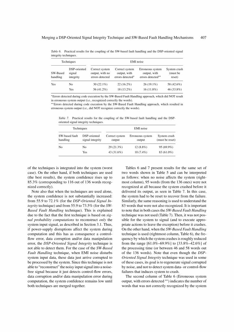
Table 6. Practical results for the coupling of the SW-based fault handling and the DSP-oriented signalintegrity techniques.
Techniques EMI noise
DSP-oriented Correct system Correct system Erroneous system System crashSW-Based signal output, with no output, with output, with (must behandling integrity errors detected errors detected∗ errors detected∗∗ reset)
Yes No 30 (22.1%) 22 (16.2%) 26 (19.1%) 58 (42.6%)
Yes 56 (41.2%) 18 (13.2%) 16 (11.8%) 46 (33.8%)
∗Errors detected during code execution by the SW-Based Fault Handling approach, which did NOT resultin erroneous system output (i.e., recognized correctly the words).∗∗Errors detected during code execution by the SW-Based Fault Handling approach, which resulted inerroneous system output (i.e., did NOT recognize correctly the words).
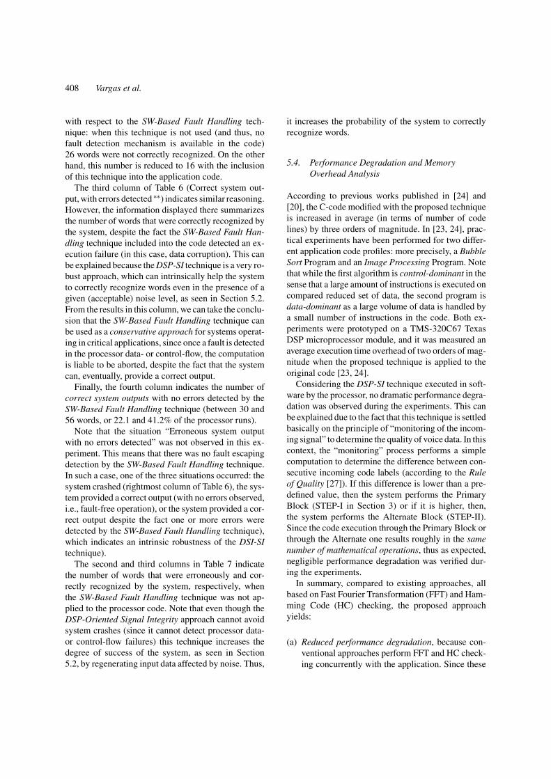
Table 7. Practical results for the coupling of the SW-based fault handling and the DSP-oriented signal integrity techniques.
Techniques EMI noise
SW-based fault DSP-oriented Correct system Erroneous system System crashhandling signal integrity output output (must be reset)
No No 29 (21.3%) 12 (8.8%) 95 (69.9%)
Yes 43 (31.6%) 10 (7.4%) 83 (61.0%)
of the techniques is integrated into the system (worstcase). On the other hand, if both techniques are used(the best results), the system confidence rises up to85.3% (corresponding to 116 out of 136 words recog-nized correctly).
Note also that when the techniques are used alone,the system confidence is not substantially increased:from 55.9 to 72.1% (for the DSP-Oriented Signal In-tegrity technique) and from 55.9 to 73.5% (for the SW-Based Fault Handling technique). This is explaineddue to the fact that the first technique is based on sig-nal probability computations to reconstruct only thesystem input signal, as described in Section 3.1. Thus,if power-supply disruptions affect the system duringcomputation and this has as consequence a control-flow error, data corruption and/or data manipulationerror, the DSP-Oriented Signal Integrity technique isnot able to detect them. For the case of the SW-BasedFault Handling technique, when EMI noise disturbssystem input data, these data just arrive corrupted tobe processed by the system. Since this technique is notable to “reconstruct” the noisy input signal into a noise-free signal because it just detects control-flow errors,data corruption and/or data manipulation error duringcomputation, the system confidence remains low untilboth techniques are merged together.
Tables 6 and 7 present results for the same set oftwo words shown in Table 5 and can be interpretedas follows: when no noise affects the system (right-most column), 95 words (from the 136 ones) were notrecognized at all because the system crashed before itdelivered its output, as seen in Table 7. In this case,the system had to be reset to recover from the failure.Similarly, the same reasoning is used to understand the83 words that were not also recognized. It is importantto note that in both cases the SW-Based Fault Handlingtechnique was not used (Table 7). Then, it was not pos-sible for the system to signal (and to execute appro-priate actions to leave the exception) before it crashes.On the other hand, when the SW-Based Fault Handlingtechnique is used (rightmost column, Table 6), the fre-quency by which the system crashes is roughly reducedfrom the range [61.0%–69.9%] to [33.8%–42.6%] ofthe processing time (or between 46 and 58 words outof the 136 words). Note that even though the DSP-Oriented Signal Integrity technique was used in someof these cases, its goal is to regenerate signal corruptedby noise, and not to detect system data- or control-flowfailures that induces system to crash.
The second column of Table 6 (Erroneous systemoutput, with errors detected ∗∗) indicates the number ofwords that was not correctly recognized by the system
408 Vargas et al.
with respect to the SW-Based Fault Handling tech-nique: when this technique is not used (and thus, nofault detection mechanism is available in the code)26 words were not correctly recognized. On the otherhand, this number is reduced to 16 with the inclusionof this technique into the application code.
The third column of Table 6 (Correct system out-put, with errors detected ∗∗) indicates similar reasoning.However, the information displayed there summarizesthe number of words that were correctly recognized bythe system, despite the fact the SW-Based Fault Han-dling technique included into the code detected an ex-ecution failure (in this case, data corruption). This canbe explained because the DSP-SI technique is a very ro-bust approach, which can intrinsically help the systemto correctly recognize words even in the presence of agiven (acceptable) noise level, as seen in Section 5.2.From the results in this column, we can take the conclu-sion that the SW-Based Fault Handling technique canbe used as a conservative approach for systems operat-ing in critical applications, since once a fault is detectedin the processor data- or control-flow, the computationis liable to be aborted, despite the fact that the systemcan, eventually, provide a correct output.
Finally, the fourth column indicates the number ofcorrect system outputs with no errors detected by theSW-Based Fault Handling technique (between 30 and56 words, or 22.1 and 41.2% of the processor runs).
Note that the situation “Erroneous system outputwith no errors detected” was not observed in this ex-periment. This means that there was no fault escapingdetection by the SW-Based Fault Handling technique.In such a case, one of the three situations occurred: thesystem crashed (rightmost column of Table 6), the sys-tem provided a correct output (with no errors observed,i.e., fault-free operation), or the system provided a cor-rect output despite the fact one or more errors weredetected by the SW-Based Fault Handling technique),which indicates an intrinsic robustness of the DSI-SItechnique).
The second and third columns in Table 7 indicatethe number of words that were erroneously and cor-rectly recognized by the system, respectively, whenthe SW-Based Fault Handling technique was not ap-plied to the processor code. Note that even though theDSP-Oriented Signal Integrity approach cannot avoidsystem crashes (since it cannot detect processor data-or control-flow failures) this technique increases thedegree of success of the system, as seen in Section5.2, by regenerating input data affected by noise. Thus,
it increases the probability of the system to correctlyrecognize words.
5.4. Performance Degradation and MemoryOverhead Analysis
According to previous works published in [24] and[20], the C-code modified with the proposed techniqueis increased in average (in terms of number of codelines) by three orders of magnitude. In [23, 24], prac-tical experiments have been performed for two differ-ent application code profiles: more precisely, a BubbleSort Program and an Image Processing Program. Notethat while the first algorithm is control-dominant in thesense that a large amount of instructions is executed oncompared reduced set of data, the second program isdata-dominant as a large volume of data is handled bya small number of instructions in the code. Both ex-periments were prototyped on a TMS-320C67 TexasDSP microprocessor module, and it was measured anaverage execution time overhead of two orders of mag-nitude when the proposed technique is applied to theoriginal code [23, 24].
Considering the DSP-SI technique executed in soft-ware by the processor, no dramatic performance degra-dation was observed during the experiments. This canbe explained due to the fact that this technique is settledbasically on the principle of “monitoring of the incom-ing signal” to determine the quality of voice data. In thiscontext, the “monitoring” process performs a simplecomputation to determine the difference between con-secutive incoming code labels (according to the Ruleof Quality [27]). If this difference is lower than a pre-defined value, then the system performs the PrimaryBlock (STEP-I in Section 3) or if it is higher, then,the system performs the Alternate Block (STEP-II).Since the code execution through the Primary Block orthrough the Alternate one results roughly in the samenumber of mathematical operations, thus as expected,negligible performance degradation was verified dur-ing the experiments.
In summary, compared to existing approaches, allbased on Fast Fourier Transformation (FFT) and Ham-ming Code (HC) checking, the proposed approachyields:
(a) Reduced performance degradation, because con-ventional approaches perform FFT and HC check-ing concurrently with the application. Since these
Merging a DSP-Oriented Signal Integrity Technique and SW-Based Fault Handling Mechanisms 409
approaches are based on very high-demand com-putations, even though we did not implement themin our experiments to explicitly compare with ourproposition, it is obvious to expect a much lowersystem performance degradation as consequenceof applying our approach, due to the simple com-putations performed (e.g., logic comparisons todetermine the difference between two consecu-tive incoming code labels (Rule of Quality), andpseudo-random generation of code labels in orderto reconstruct noisy parts of the original signal).
(b) Reduced memory area overhead. The DSP-SI ap-proach requires the implementation of the Code La-bels Sequence Simulator (CLSS) Block, the ViterbiAlgorithm Controller (VAC) and Sub-system-II, asseen in Fig. 2. These blocks are: a pseudo-randomcode labels sequence generator (CLSS), a compara-tor that performs a (logic) comparison betweentwo consecutive incoming code labels and takesa proper decision (VAC), and a finite-state machinethat implements the Hidden Markov Model for ev-ery word of the system (Sub-system-II), respec-tively. These blocks are very simple to be imple-mented either in hardware or in software, and donot require a complex specification process. Notethat for the SW-Based Fault Handling technique,the memory overhead due to extra space requiredto store redundant code such as duplicated vari-ables and specific instructions for checkpoint mon-itoring is increased by three orders of magnitude.This increase is not very optimistic. Aiming tosolve this problem, we are, at present, designingan infrastructure-intellectual property (I-IP) coreto perform the SW-Based Fault Handling techniqueby checking rules #1 to #6 and to execute part ofthe DSP-SI technique [1]. The final goal of this I-IPis not only to minimize the processor performancedegradation by reducing the extra code added tothe application, but mainly to reduce memory over-head induced by the extra space required to storeredundant code such as duplicated variables andspecific instructions for checkpoint monitoring inthe SW-Based Fault Handling technique.
(c) Similar signal quality improvement, according todata found in the literature [18, 19, 28].
6. Conclusion
We presented a study aiming to improve the reliabil-ity of digital signal processing (DSP) systems operat-
ing in real noisy (electromagnetic interference—EMI)environments. The proposed approach is the merg-ing of two techniques: one based on DSP algorithmsused to filter noise in real-time by means of a “re-construction” of the noisy input signal, and the otheris based on SW solutions to guarantee fault detectionat the application-code level. The DSP-oriented tech-nique can be either implemented in HW or SW, whilethe SW-based fault detection mechanisms are imple-mented at the processor source-code level. Thus, thisapproach can be easily applied to commercial off-the-shelf (COTS) microprocessor-based systems. The maincharacteristics of the proposed approach are:
(a) The DSP-based technique proposed to improve thesignal-to-noise ratio (SNR) is essentially a modi-fication of the classic Recovery Blocks Scheme.Aiming to improve input signal quality, the pro-posed DSP-based technique is split in two steps: inSTEP-I, the algorithm performs in the “Primary”Block an on-line checking of the incoming dataquality. If the signal is close to predefined (ac-ceptable) values, the system remains continuouslyin this monitoring procedure. However, if the ob-served input signal quality is not the expected one(i.e., offending a Fundamental Rule of Quality)[27], the algorithm moves to STEP-II (in the “Al-ternate” Block) to perform the “reconstruction” ofthe incoming information in order for the systemto operate as fit for purpose.
(b) The SW-based fault handling technique is fully im-plemented in software [20, 24], throughout modi-fications of the processor C-code. The techniqueis divided into two steps according to the typeof information that must be preserved despite thepresence of noise: i.e., faults affecting the proces-sor control flow, and faults affecting the handleddata.
When compared to conventional approaches usingFast Fourier Transform (FFT) and Hamming Code,the primary benefit of the proposed approach is to im-prove system reliability by means of a considerably lowcomplexity, reasonably low performance degradationand reduced area overhead required for implementa-tion (i.e., extra memory space to store redundant codesuch as duplicated variables and specific instructionsfor checkpoint monitoring).
To illustrate the proposed approach, we implementeda HW/SW prototype to operate as a speech recognition

410 Vargas et al.
system (SRS). This prototype was tested under a home-tailored EMI environment according to the IEC 61000-4-29 International Standard Normative. The obtainedresults indicate that the proposed approach can effec-tively improve the reliability of DSP systems operatingin real noise (EMI) environments.
Acknowledgment
This work is partially supported by CNPq.
Notes
1. Around 3000 lines of code on a PC-based computer: 2000lines dedicated for the recognition and training procedure of theMarkov Models; 400 lines for the signal A/D sampling and filter-ing procedure; and 600 lines for interfacing the system with thedatabase TIMIT.
2. The processor C-code was composed by around 800 lines.3. To map the HW part into the FPGA, it was used 7672 CLBs
(Configurable Logic Blocks).4. http://www.ti.com, May 2003.5. Noise was injected into the input speech signal (i.e., into the code
labels sequence) by using a mixing function to modify arbitrarilyby a factor of 10, 20, 30, 40, 50 or 60 percent the population of0’s and 1’s that form the code labels sequence.
References
1. L. Bolzani, M. Rebaudengo, M. Sonza Reorda, F. Vargas, andM. Violante, “Hybrid Soft Error Detection by Means of Infras-tructure IP Cores,” in Proceedings of the 10th IEEE On-Line TestSymposium—IOLTS’04, Madeira Island, Portugal, July 12–14,2004.
2. R. Chillarege and N.S. Bowen, “Understanding Large SystemsFailures—A Fault Injection Experiment,” in Proceedings of the19th International Symposium on Fault-Tolerant Computing—FTCS-19, pp. 356–363, 1989.
3. D. Clark, “Speech Recognition: The Wireless Interface Revo-lution,” IEEE Computer Magazine, vol. 34, no. 3, pp. 16–18,2001.
4. M. Dekker, Digital Speech Processing, Synthesis, and Recogni-tion, 1989. ISBN: 0824779657.
5. J. Deller, J.G. Proakis, and J.H.L. Hansen, Discrete-Time Pro-cessing of Speech Signals, New York: Macmillan, 1993.
6. R.D.R. Fagundes, F. Vargas, and D. Barros Jr., “A Viterbi Al-gorithm Implementation Using Hardware/Software Co-Designin Speech Recognition Systems,” in Proceedings of the Interna-tional Association of Science and Technology for DevelopmentConference—IASTED’2000, Marbella, Spain, Sep. 19–22, 2000,pp. 205–209 (http://www.iasted.com, Sep. 2000).
7. F. Fiori, S. Benelli, G. Gaidano, and V. Pozzolo, “Investigation onVLSIs’ Input Ports Susceptibility to Conduct RF Interference,”IEEE Transactions on Electromagnetic Compatibility, pp. 326–329, 1997.
8. International Electrotechnical Commission, International Stan-dard IEC 61000-4-29 Normative. www.iec.ch, May 2003.
9. J. Makhoul, “Linear Prediction: A Tutorial Review,” Proceed-ings of the IEEE, vol. 63, no. 4, pp. 561–580, 1975.
10. Microcontroller Texas MSP430F149. (www.ti.com, May 2003)11. G. Miremadi, J. Karlsson, U. Gunneflo, and J. Torin, “Two
Software Techniques for On-Line Error Detection,” IEEETransactions on Electromagnetic Compatibility, pp. 328–335,1992.
12. G. Miremadi and J. Torin, “Evaluating Processor-Behaviorand Three Error-Detection Mechanisms Using Physical Fault-Injection,” IEEE Transactions on Reliability, vol. 44, no. 3,pp. 441–454, 1995.
13. N. Oh, P.P. Shirvani, and E.J. McCluskey, “Control-Flow Check-ing by Software Signatures,” IEEE Transactions on Reliability,vol. 51, no. 2, pp. 111–122, 2002.
14. R. Perez, “Signal Integrity Issues in ASIC and FPGA Design,” inProceedings of the International Symposium on ElectromagneticCompatibility—EMC’1997, vol. 2, 1997, pp. 334–339.
15. D.K. Pradhan, Fault-Tolerant Computer System Design.Prentice-Hall, 1996, p. 544.
16. J.G. Proakis and D.G. Manolakis, Digital Signal Processing:Principles, Algorithms and Applications, 3rd edn., Prentice Hall,Oct. 5, 1995. ISBN: 0133737624.
17. L.R. Rabiner and B.H. Juang, Fundamentals of Speech Recog-nition, New Jersey: Prentice Hall, 1993.
18. L.R. Rabiner and S.E. Levinson, “A Speaker-Independent,Syntax-Directed, Connected Word Recognition System Basedon Hidden Markov Models and Level Building,” IEEE Trans-actions on Acoustics, Speech, and Signal Processing, vol. 33,no. 3, pp. 561–573, 1985.
19. L.R. Rabiner, J.G. Wilpon, and F.K. Soong, “High PerformanceConnected Digit Recognition Using Hidden Markov Models,”IEEE Transactions on Acoustics, Speech, and Signal Processing,vol. 37, no. 8, pp. 1214–1225, 1989.
20. M. Rebaudengo, M. Sonza Reorda, M. Torchiano, and M.Violante, “Soft-Error Detection Through Software Fault-Tolerance Techniques,” in Proceedings of the IEEE Design forTestability Workshop -DFT’99, 1999.
21. T. Steinecke, “Design-In for EMC on CMOS large-Scale Inte-grated Circuits,” in Proceedings of the International Symposiumon Electromagnetic Compatibility—EMC’2001, vol. 2, 2001,pp. 910–915.
22. J. Tzimenakis and D. Holland, Understanding the EMC Direc-tive: Everything Made Clear, Gainspeed Ltd, UK, 2000.
23. F. Vargas, D. Becker Brum, D. Prestes, L. Bolzani, E. Rhod, andM. Sonza Reorda, “SW-Based Fault Handling Mechanisms toCope with EMI in Embedded Electronics: Are They A GoodRemedy? A Case Study on a COTS Microprocessor,” in Pro-ceedings of the 9th IEEE On-Line Test Symposium—IOLTS’03,Kos Island, Greece, July 07–09, 2003.
24. F. Vargas, D.B. Brum, D. Prestes, L. Bolzani, and D. Lettnin,“On the Mitigation of Conducted Electromagnetic Immunityby Means of SW-Based Fault Handling Mechanisms,” in Pro-ceedings of the 4th IEEE Latin American Test Workshop—LATW’03, Natal, Brazil, Feb. 16–19, 2003, pp. 130–135.(www.ee.pucrs.br/∼latw, Feb. 2003)
25. F. Vargas, R.D.R. Fagundes, and D. Barros Jr., “Orient-ing Redundancy and HW/SW Codesign Techniques TowardsSpeech Recognition Systems,” in Proceedings of the 2nd IEEE

Merging a DSP-Oriented Signal Integrity Technique and SW-Based Fault Handling Mechanisms 411
Latin American Test Workshop—LATW2001, Cancun: Mexico,Feb. 11–14, pp. 226–233, 2001.
26. F. Vargas, R.D.R. Fagundes, and D. Barros Jr., “A FPGA-BasedViterbi Algorithm Implementation for Speech Recognition Sys-tems,” in Proceedings of the 26th IEEE International Conferenceon Acoustics, Speech and Signal Processing—ICASSP2001, SaltLake City, Utah, USA, May 7–11, 2001, p. 352, Proceedings onCD. (http://www.icassp2001.org, May 2001).
27. F. Vargas, R.D.R. Fagundes, and D. Barros Jr, “A New On-Line Robust Approach to Design Noise-Immune Speech Recog-nition Systems,” Journal of Electronic Testing: Theory andApplications—JETTA, Kluwer Academic Publishers, New York,USA, vol. 19, Feb. 2003, pp. 61–72.
28. A.J. Viterbi, “Convolutional Codes and Their Performance inCommunication Systems,” IEEE Transactions on Communica-tions Tech, vol. Com-19, no. 5, pp. 751–772, 1971.
29. N.L. Whyman and J.F. Dawson, “Modelling RF Interfer-ence Effects in Integrated Circuits,” in Proceedings of theInternational Symposium on Electromagnetic Compatibility—EMC’2001, vol. 2, 2001, pp. 1203–1208.
30. www.cad.polito.it/cooperations/TOSCA/TOSCA.htm, May2003.
31. www.polito.it/∼sonza, May 2003.
Fabian Vargas received his B.S. degree in EE from the Catholic Uni-versity (PUCRS), Brazil, in 1988, the M.Sc. degree in CS from theFederal University of Rio Grande do Sul (UFRGS), also in Brazil, in1991, and the Ph.D. degree from the Institut National Polytechniquede Grenoble (INPG), France, in 1995. Since 1996 he is AssociateProfessor at the Catholic University. In 1997 he founded and haschaired since then the Latin American Group of the Test Technol-ogy Technical Council (TTTC) of the IEEE Computer Society. His
research interests are Design of Fault-Tolerant Systems, On-LineTesting, System-Level Reliability Estimation.
Rubem D. Fagundes received the B.S. degree in EE from theCatholic University (PUCRS), Brazil) in 1989, the M.Sc. degreefrom the University of Sao Paulo (Brazil), in 1993, and the Ph.D.degree from the University of Sao Paulo/Centre de Recherche enInformatique de Montreal (CRIM), Canada, as a major result of acollaborative project between these Institutions in 1998. Since 1990he is Associate Professor at the Catholic University. His researchinterests are Signal Processing, Speech Processing and Recognition,Artificial Intelligence and Pattern Recognition.
Daniel Barros Jr. Received the B.S. and the M.Sc. degrees in Elec-trical Engineering from the Catholic University (PUCRS), Brazil in1999 and 2002, respectively. Since 2002 he is Associate Professor atthe same university. His research interests are Pattern Recognition,Design for Testability, BIST, and FPGA-Based Fast Prototyping.
Diogo Becker de Brum is undergraduate student in Automation andControl Engineering at the Catholic University (PUCRS), Brazil,since January 1999. He is a grant holder at SiSC Labs since March2001. His research interests are Design of Fault-Tolerant Systems,Signal Processing and Pattern Recognition.
Eduardo Rhod is undergraduate student in Automation and ControlEngineering at the Catholic University (PUCRS), Brazil, since Jan-uary 1999. He is a grant holder at SiSC Labs since January 2002. Hisresearch interests are FPGA-Based Fast Prototyping, and PervasiveComputing.