
Megavoltage Image-Based Dynamic Multileaf Collimator Tracking of a NiTi Stent in Porcine Lungs on a...
17
MV image-based dynamic MLC tracking of a NiTi stent in pig lungs on a linear accelerator Per R Poulsen, Ph.D. 1 , Jesper Carl, Ph.D. 2 , Jane Nielsen, M.Sc. 2 , Martin S Nielsen, M.Sc. 2 , Jakob B Thomsen, M.Sc. 2 , Henrik K Jensen, M.D. 3 , Benedict Kjærgaard, M.D. 4 , Peter R Zepernick, M.D. 4 , Esben Worm, M.Sc. 1 , Walther Fledelius, Ph.D. 1 , Byungchul Cho, Ph.D. 5 , Amit Sawant, Ph.D. 6 , Dan Ruan, Ph.D. 7 , and Paul J Keall, Ph.D. 8,9 1 Department of Oncology, Aarhus University Hospital, Aarhus, Denmark 2 Department of Medical Physics, Aalborg Hospital, University of Aarhus, Aalborg, Denmark 3 Department of Pulmonary Medicine, Aalborg Hospital, University of Aarhus, Aalborg, Denmark 4 Department of Thoracic Surgery, Aalborg Hospital, University of Aarhus, Aalborg, Denmark 5 Department of Radiation Oncology, Asan Medical Center, University of Ulsan College of Medicine, Seoul, Korea 6 UT Southwestern Medical Center, Dallas, TX 7 Department of Radiation Oncology, University of California, Los Angeles 8 Department of Radiation Oncology, Stanford University, Stanford, CA 9 Sydney Medical School, The University of Sydney, Australia Abstract Purpose: To investigate the accuracy and potential limitations of MV image-based dynamic MLC tracking in a porcine model on a linear accelerator. Methods and Materials: A thermo-expandable NiTi stent designed for kV x-ray visualization of lung lesions was inserted into the bronchia of three anaesthetized Göttingen minipigs. A 4DCT scan was used for planning a 5-field conformal treatment with circular MLC apertures. A 22.5Gy single fraction treatment was delivered to the pigs. The peak-to-peak stent motion was 3-8mm with breathing periods of 1.2-4 seconds. Prior to treatment, x-ray images were used for image- guided setup based on the stent. During treatment delivery, continuous portal images were acquired at 7.5Hz. The stent was segmented in the images and used for continuous adaptation of the MLC aperture. Offline, the tracking error in beam’s eye view of the MV beam was calculated for each image as the difference between the MLC aperture center and the segmented stent position. The standard deviations of the systematic error Σ and the random error σ were determined and compared with the would-be errors for a non-tracking treatment with pre- treatment image-guided setup. © 2011 Elsevier Inc. All rights reserved. Corresponding author: Per Rugaard Poulsen, Aarhus University Hospital, Department of Oncology, Nr Brogade 44, 8000 Aarhus C, Denmark, [email protected], Tel: +45 8949 2651, Fax: +45 8949 4522 . Publisher's Disclaimer: This is a PDF file of an unedited manuscript that has been accepted for publication. As a service to our customers we are providing this early version of the manuscript. The manuscript will undergo copyediting, typesetting, and review of the resulting proof before it is published in its final citable form. Please note that during the production process errors may be discovered which could affect the content, and all legal disclaimers that apply to the journal pertain. Conflict of interest notification: This work was partially supported by Varian Medical Systems (Palo Alto, CA) and by Pnn Medical (Denmark). NIH Public Access Author Manuscript Int J Radiat Oncol Biol Phys. Author manuscript; available in PMC 2013 February 1. Published in final edited form as: Int J Radiat Oncol Biol Phys. 2012 February 1; 82(2): e321–e327. doi:10.1016/j.ijrobp.2011.03.023. NIH-PA Author Manuscript NIH-PA Author Manuscript NIH-PA Author Manuscript
Transcript of Megavoltage Image-Based Dynamic Multileaf Collimator Tracking of a NiTi Stent in Porcine Lungs on a...

MV image-based dynamic MLC tracking of a NiTi stent in piglungs on a linear accelerator
Per R Poulsen, Ph.D.1, Jesper Carl, Ph.D.2, Jane Nielsen, M.Sc.2, Martin S Nielsen, M.Sc.2,Jakob B Thomsen, M.Sc.2, Henrik K Jensen, M.D.3, Benedict Kjærgaard, M.D.4, Peter RZepernick, M.D.4, Esben Worm, M.Sc.1, Walther Fledelius, Ph.D.1, Byungchul Cho, Ph.D.5,Amit Sawant, Ph.D.6, Dan Ruan, Ph.D.7, and Paul J Keall, Ph.D.8,9
1Department of Oncology, Aarhus University Hospital, Aarhus, Denmark2Department of Medical Physics, Aalborg Hospital, University of Aarhus, Aalborg, Denmark3Department of Pulmonary Medicine, Aalborg Hospital, University of Aarhus, Aalborg, Denmark4Department of Thoracic Surgery, Aalborg Hospital, University of Aarhus, Aalborg, Denmark5Department of Radiation Oncology, Asan Medical Center, University of Ulsan College ofMedicine, Seoul, Korea6UT Southwestern Medical Center, Dallas, TX7Department of Radiation Oncology, University of California, Los Angeles8Department of Radiation Oncology, Stanford University, Stanford, CA9Sydney Medical School, The University of Sydney, Australia
AbstractPurpose: To investigate the accuracy and potential limitations of MV image-based dynamicMLC tracking in a porcine model on a linear accelerator.
Methods and Materials: A thermo-expandable NiTi stent designed for kV x-ray visualizationof lung lesions was inserted into the bronchia of three anaesthetized Göttingen minipigs. A 4DCTscan was used for planning a 5-field conformal treatment with circular MLC apertures. A 22.5Gysingle fraction treatment was delivered to the pigs. The peak-to-peak stent motion was 3-8mmwith breathing periods of 1.2-4 seconds. Prior to treatment, x-ray images were used for image-guided setup based on the stent. During treatment delivery, continuous portal images wereacquired at 7.5Hz. The stent was segmented in the images and used for continuous adaptation ofthe MLC aperture. Offline, the tracking error in beam’s eye view of the MV beam was calculatedfor each image as the difference between the MLC aperture center and the segmented stentposition. The standard deviations of the systematic error Σ and the random error σ weredetermined and compared with the would-be errors for a non-tracking treatment with pre-treatment image-guided setup.
© 2011 Elsevier Inc. All rights reserved.Corresponding author: Per Rugaard Poulsen, Aarhus University Hospital, Department of Oncology, Nr Brogade 44, 8000 Aarhus C,Denmark, [email protected], Tel: +45 8949 2651, Fax: +45 8949 4522 .Publisher's Disclaimer: This is a PDF file of an unedited manuscript that has been accepted for publication. As a service to ourcustomers we are providing this early version of the manuscript. The manuscript will undergo copyediting, typesetting, and review ofthe resulting proof before it is published in its final citable form. Please note that during the production process errors may bediscovered which could affect the content, and all legal disclaimers that apply to the journal pertain.Conflict of interest notification:This work was partially supported by Varian Medical Systems (Palo Alto, CA) and by Pnn Medical (Denmark).
NIH Public AccessAuthor ManuscriptInt J Radiat Oncol Biol Phys. Author manuscript; available in PMC 2013 February 1.
Published in final edited form as:Int J Radiat Oncol Biol Phys. 2012 February 1; 82(2): e321–e327. doi:10.1016/j.ijrobp.2011.03.023.
NIH
-PA Author Manuscript
NIH
-PA Author Manuscript
NIH
-PA Author Manuscript

Results: Reliable stent segmentation was obtained for 11 out of 15 fields. Segmentation failuresoccurred when image contrast was dominated by overlapping anatomical structures (ribs,diaphragm) rather than by the stent, which was designed for kV rather than MV x-ray visibility.For the 11 fields with reliable segmentation, Σ was 0.5mm/0.4mm in the two imager directions,while σ was 0.5mm/1.1mm. Without tracking, Σ and σ would have been 1.7mm/1.4mm and0.8mm/1.4mm, respectively.
Conclusion: For the first time, in vivo DMLC tracking has been demonstrated on a linearaccelerator showing the potential for improved targeting accuracy. The study mimicked theenvisioned patient workflow of future patient treatments. Clinical implementation of MV image-based tracking would require markers designed for MV-visibility.
KeywordsImage-guided radiotherapy; intrafraction motion; tumor tracking; Dynamic MLC tracking
INTRODUCTIONMost tumors move during radiotherapy treatment delivery (1-3). This intrafraction motion isusually accounted for by treating a static volume that includes both the tumor and itsanticipated motion with a high probability (4). While this approach often causes increasedhealthy tissue irradiation with potentially enhanced side effects, part of the tumor may stillmove outside the pre-designed target volume leading to lower tumor doses than prescribed.An alternative to the static target volume approach is tumor tracking, where real-time tumorposition monitoring is used for repeated realignment of the treatment beam to the tumorposition.
To date, tumor tracking has only been implemented clinically for the robotic Cyberknifesystem (Accuray Inc., Sunnyvale, CA) (5, 6). However, tracking with conventional gantry-mounted linear accelerators has been the subject of several phantom studies that used eithercontinuous couch position corrections (7) or dynamic multileaf collimator (DMLC) tracking(8, 9) for target motion compensation. In this study, the first demonstration of in vivoDMLC tracking in a mammal is presented and the accuracy and potential limitations of thetracking is investigated. The equipment and workflow in the study is analogous to that ofcurrent patient stereotactic body radiotherapy (SBRT) treatments.
METHODS AND MATERIALSMV image based DMLC tracking
Three Göttingen minipigs were included in the study which was carried out at AalborgHospital, Aarhus University Hospital, Denmark. The study was approved by The AnimalEthics Council under the Danish Justice Department (journal no. 2008/561-1473). A thermo-expandable NiTi stent (7 mm length, 3.5-6 mm diameter, Pnn Medical, Denmark) designedfor kV x-ray visualization of lung lesions was inserted into the bronchia of the pigs underbronchoscope guidance (10), see Fig. 1. Immediately after the lung stent insertion, aplanning 4DCT scan was acquired while the pigs were intubated and ventilated using arespirator. Anesthesia was maintained during these procedures. The mid-expiration CTphase was used for planning of a 6MV 5-field conformal treatment with 6 cm circular MLCapertures and the isocenter located at the stent. For all fields, the collimator rotation was 90degrees resulting in MLC leaf motion parallel to the cranio-caudal (CC) direction.
Four weeks after stent insertion, the treatment was delivered to the pigs with a Varian ClinaciX linear accelerator equipped with an AS1000 portal imager on an ExactArm, a Millennium
Poulsen et al. Page 2
Int J Radiat Oncol Biol Phys. Author manuscript; available in PMC 2013 February 1.
NIH
-PA Author Manuscript
NIH
-PA Author Manuscript
NIH
-PA Author Manuscript

MLC, and a prototype DMLC tracking system (Varian Medical Systems, Palo Alto, CA).Each pig received a single fraction with 22.5 Gy to the isocenter delivered with a dose rateof 600 MU per minute. The pigs were anaesthetized before the treatment and keptanaesthetized until they were sacrificed after the treatment. Two pigs breathed freely duringtreatment and one pig was ventilated by the respirator. For the pre-treatment alignment, twosequential x-ray images were acquired with an ExacTrac X-ray system (BrainLAB AG,Feldkirchen, Germany) and used for image guided couch correction based on the stentlocation. If the stent was captured in different positions in the x-ray images due torespiratory motion the resulting error in the stent registration with the planning CT scan wasdistributed evenly among the two x-ray images. Before each field delivery, 10-20continuous MV images were acquired at 7.5 Hz and stored on the MV imager work station.The exposure dose was 1.33 MU and the exposure time was 133 ms for each image. Thesource-imager distance for the MV imager was 150 cm, resulting in a pixel side length of0.261 mm when scaled to isocenter distance. In an in-house marker segmentation program(11), a rectangular area with 5-13 mm side lengths that encompassed the stent was manuallyselected in the first pre-field MV image and used as a template for testing template basedsegmentation in the pre-field images that followed. If the segmentation succeeded, the fielddelivery was ready to start. If the segmentation failed in one or more images, an alternativetemplate was selected among the pre-field MV images and its use for template basedsegmentation was tested in the other images.
During field delivery, continuous MV images were acquired at 7.5 Hz and used for DMLCtracking as illustrated in Fig. 2. When a new MV image was stored on the MV work station,the segmentation program identified the stent in the image by using the pre-field selectedtemplate and sent the projected stent position to a tracking program on a dedicated trackingcomputer. The tracking program first estimated the 3D stent position from the 2D projectedposition by assuming that the stent was located in a plane at isocenter distance (100 cm)from the linac MV source. Then a kernel density estimation based prediction algorithm (12)was applied to account for the tracking system latency of 400 ms (13). Finally, the MLCaperture was adjusted to the resulting 3D stent position estimation (14). The prediction wasnot applied in the first 8 seconds of each field delivery because a training data set for theprediction algorithm needed to be established first. The training data set was either all MVimages acquired for the field (in the period from 8 to 20 seconds) or a continuously movingwindow of the MV images acquired in the most recent 20 seconds. The mean field deliveryduration was 59 s (range: 51-71 s) with a mean of 59 monitor units per field (range: 506-708MU). The treatment duration from acquisition of the first pre-treatment MV image totreatment completion ranged from 30 to 35 minutes for the three treatments.
After the treatments, the tracking error in beam’s eye view of the treatment beam wascalculated for each intra-field MV image as the difference between the segmented stentposition and the MLC aperture center position. For comparison, the error without trackingwas calculated as the difference between the intra-field stent positions and the MLC aperturecenter position after pre-treatment alignment (i.e. the MLC aperture in the pre-field imagesbefore start of the tracking). For each individual field, the root-mean-square (rms), the meanand the standard deviation (SD) of the errors were calculated with and without tracking inboth directions of the MV imager. The group mean error M was calculated as the mean ofthe individual mean errors. The group systematic error Σ was calculated as the SD of theindividual mean errors. The group random error σ was calculated as the root-mean-square ofthe individual SD errors. Fields without successful segmentation in the pre-field imageswere not included in this analysis.
Poulsen et al. Page 3
Int J Radiat Oncol Biol Phys. Author manuscript; available in PMC 2013 February 1.
NIH
-PA Author Manuscript
NIH
-PA Author Manuscript
NIH
-PA Author Manuscript
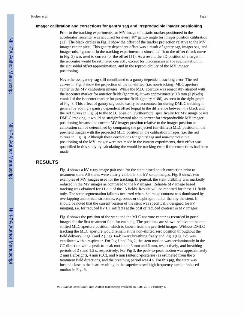
Imager calibration and corrections for gantry sag and irreproducible imager positioningPrior to the tracking experiments, an MV image of a static marker positioned in theaccelerator isocenter was acquired for every 10° gantry angle for imager position calibration(11). The black circles in Fig. 3 show the offset of the marker projection relative to the MVimager center pixel. This gantry dependent offset was a result of gantry sag, imager sag, andimager misalignment. In the tracking experiments, a sinusoidal fit to the offset (black curvein Fig. 3) was used to correct for the offset (11). As a result, the 3D position of a target inthe isocenter would be estimated correctly except for inaccuracies in the segmentation, inthe sinusoidal offset approximation, and in the reproducibility of the MV imagerpositioning.
Nevertheless, gantry sag still contributed to a gantry dependent tracking error. The redcurves in Fig. 3 show the projection of the un-shifted (i.e. non-tracking) MLC aperturecenter in the MV calibration images. While the MLC aperture was reasonably aligned withthe isocenter marker for anterior fields (gantry 0), it was approximately 0.8 mm (3 pixels)cranial of the isocenter marker for posterior fields (gantry ±180), as seen in the right graphof Fig. 3. This effect of gantry sag could easily be accounted for during DMLC tracking ingeneral by adding a gantry dependent offset (equal to the difference between the black andthe red curves in Fig. 3) to the MLC position. Furthermore, specifically for MV image basedDMLC tracking, it would be straightforward also to correct for irreproducible MV imagerpositioning because the current MV imager position relative to the imager position atcalibration can be determined by comparing the projected (un-shifted) MLC position in thepre-field images with the projected MLC position in the calibration images (i.e. the redcurves in Fig. 3). Although these corrections for gantry sag and non-reproduciblepositioning of the MV imager were not made in the current experiments, their effect wasquantified in this study by calculating the would-be tracking error if the corrections had beenmade.
RESULTSFig. 4 shows a kV x-ray image pair used for the stent based couch correction prior totreatment start. All stents were clearly visible in the kV setup images. Fig. 5 shows twoexamples of MV images used for the tracking. In general, the stent visibility was markedlyreduced in the MV images as compared to the kV images. Reliable MV image basedtracking was obtained for 11 out of the 15 fields. Results will be reported for these 11 fieldsonly. The stent segmentation failures occurred when the image contrast was dominated byoverlapping anatomical structures, e.g. bones or diaphragm, rather than by the stent. Itshould be noted that the current version of the stent was specifically designed for kVimaging, i.e. for reduced kV CT artifacts at the cost of reduced contrast in MV images.
Fig. 6 shows the position of the stent and the MLC aperture center as recorded in portalimages for the first treatment field for each pig. The positions are shown relative to the non-shifted MLC aperture position, which is known from the pre-field images. Without DMLCtracking the MLC aperture would remain at the non-shifted zero position throughout thefield delivery. Pigs 1 and 2 (Figs. 6a-b) were breathing freely and Pig 3 (Fig. 6c) wasventilated with a respirator. For Pig 1 and Pig 2, the stent motion was predominantly in theCC direction with a peak-to-peak motion of 3 mm and 6 mm, respectively, and breathingperiods of 2 s and 1.2 s, respectively. For Pig 3, the peak-to-peak motion was approximately2 mm (left-right), 4 mm (CC), and 6 mm (anterior-posterior) as estimated from the 5treatment field directions, and the breathing period was 4 s. For this pig, the stent waslocated close to the heart resulting in the superimposed high frequency cardiac inducedmotion in Fig. 6c.
Poulsen et al. Page 4
Int J Radiat Oncol Biol Phys. Author manuscript; available in PMC 2013 February 1.
NIH
-PA Author Manuscript
NIH
-PA Author Manuscript
NIH
-PA Author Manuscript

As seen in Fig. 6, the prediction started 8 seconds into the field delivery after acquisition ofthe first sixty MV images. In the first period without prediction, the MLC motion quiteaccurately mimicked the stent motion, but with a delay of 400 ms as seen in the figure.When prediction started, the MLC motion came into phase with the stent motion, butprediction errors also caused the MLC motion to mimic the stent motion less accurately. Thedifference between the stent position and the MLC center position in Fig. 6 is the trackingerror and the stent position relative to zero is the would-be error without tracking. The rmsvalue, standard deviation, and mean of these errors are indicated for the fields in Fig. 6. Fig.7 shows four different calculations of the rms error for each treatment field with reliablestent segmentation. Comparing the black columns (no tracking) with the red columns(tracking) shows that DMLC tracking substantially reduced the rms error for most fields.However, exceptions occurred e.g. in the Xp direction in the first field for Pig 1 (Fig. 6a andFig. 7 (upper left)). The green columns in Fig. 7 show that exclusion of the first 60 imageswhere no prediction was applied only had a small effect on the rms tracking error except forPig 2 in the Yp direction. Because of the fast breathing for this pig, the tracking latency of400 ms was comparable to half a breathing cycle (600 ms), which resulted in substantialtracking errors when the latency was uncompensated by prediction (see Fig. 6b).
As explained in the Materials and Methods section, the expected tracking error caused bygantry sag can be estimated for each field from the imager calibration curves (Fig. 3), whilethe expected error caused by irreproducible MV imager positioning can be estimated bycomparing the projected MLC position in the pre-field images with the calibration curves.Fig. 8 is a scatter plot showing the sum of these error estimations versus the actualexperimental mean tracking error. The estimated errors corresponded reasonably to theactual mean tracking errors for all fields; the largest difference being 0.3 mm. As a result, alarge part of the mean tracking error could be corrected for by shifting the MLC aperture tocounteract for the estimated error. The blue columns in Fig. 7 show that application of thiscorrection would lead to a substantial reduction in tracking errors.
Table 1 summarizes the mean rms errors for the four scenarios in Fig. 7, along with thepopulation mean error M and the standard deviations of the systemic error Σ and the randomerror σ. The table also shows 2.5Σ + 0.7σ, which is often used to quantify the setup marginneeded to ensure a minimum target dose of 95% with 90% probability (15). As shown in thetable, this margin is largely reduced by the tracking. However, the margin formalismassumes that the overall population mean M is negligible compared to Σ and σ. Since thisrequirement is not fulfilled in current tracking experiments, (Fig. 8 and Table 1) 2.5Σ + 0.7σunderestimates the necessary setup margins for these experiments. However, if thesuggested corrections for gantry sag and irreproducible imager positioning had been applied,M would be negligible and large setup margin reductions would be possible (Table 1, lastrow).
DISCUSSIONThe experiments in this study represent the first demonstration of in vivo DMLC trackingfor a mammal. As the equipment and workflow were analogous to that of patient SBRTtreatments, the demonstration is an important step towards clinical implementation ofDMLC tracking. Reliable tracking was obtained for 11 out of 15 fields showing substantialaccuracy improvements compared to on-line image-guided radiotherapy without tracking.By highlighting main advantages and disadvantages of MV image based tracking, this studycan serve as a guide for a safe clinical introduction of the tracking method. The mainadvantages of MV image based DMLC tracking are the avoidance of additional imagingdose to the patient and the direct visualization of the target (surrogate) position within thefield shape formed by the MLC leaves. Although not done in the current study, the dose for
Poulsen et al. Page 5
Int J Radiat Oncol Biol Phys. Author manuscript; available in PMC 2013 February 1.
NIH
-PA Author Manuscript
NIH
-PA Author Manuscript
NIH
-PA Author Manuscript

the pre-field images could be subtracted from the intra-field dose in order to obtain dose-neutral imaging for tracking. Furthermore, the imaging of both target and MLC in the MVimages can be used for considerable systematic error reductions by compensating forirreproducible imager positioning (Table 1, last row).
The main disadvantages of MV image based tracking are related to the MV image qualityand the tight coupling between the MV image based target localization and the treatmentdelivery. Firstly, although the setup kV images showed very good contrast for all stents, MVcontrast limitations resulted in unreliable stent segmentation, and thus failed tracking, in 4 ofthe 15 fields in this study. Therefore, markers designed for better MV visibility would beneeded for clinical implementation of MV image based tracking. Secondly, the temporallimitation of MV image based localization to the treatment delivery time hindered the use ofprediction until a sufficient training data set had been collected (8 seconds into the fielddelivery in this study). The temporal limitation of MV imaging also hampers MV imagebased gating because the MV images cannot be used to determine when to turn on the beamafter a beam-off period. Thirdly, the spatial limitation of the MV field-of-view to the MLCaperture hinders straightforward integration with intensity modulated treatments (IMRT andIMAT) because the target may be blocked by the MLC leaves. Although strategies tocircumvent this limitation have been proposed (16), MV image based DMLC tracking maybe restricted to conformal treatments and cases where the entire marker is located wellwithin the planning target volume.
A further limitation of the MV image based tracking in the current study is the lack of a full3D target position estimation. The tracking was effectively 2D tracking in the MV resolvedplane as the target was always assumed to be located at isocenter distance from the MVsource. Usually this 2D in-plane tracking will only deviate negligibly from full 3D tracking,where in-depth motion along the treatment beam axis is tracked by magnification or de-magnification of the MLC aperture (14). However, the simplification to 2D in-planetracking means that also the target position prediction (and the corresponding training dataset collection) was performed in the resolved plane of the MV imager only. Consequently, anew prediction training data set had to be established for each beam direction. Thissubstantially complicates the use of prediction for 2D in-plane tracking in arc therapy.However, a consistent 3D prediction training data set in a fixed coordinate system could beobtained by estimating the full 3D target trajectory during the rotation (17).
Despite the limitations, this study suggests that the following conservative strategy couldlead to safe clinical implementation of MV image based DMLC tracking: After implantationof markers with good MV contrast, a conformal treatment plan with standard motionmargins (15) is produced. Continuous MV images are acquired during field delivery, but notracking is performed during the first part of the field delivery. If the segmentation isreliable, the DMLC tracking is started when sufficient images for prediction training areacquired. In case of any uncertainty, the tracking is stopped, the MLC leaves are movedback to their pre-planned positions, and the remaining part of the treatment field is deliveredas a standard non-tracking treatment. As this conservative scenario does not involve marginreductions, the aim would not be a smaller treated volume. Instead, the aim would be animproved tumor dose for the 10% treatments, where standard motion margins fail to ensurea minimum CTV dose of 95% (15). If introduced carefully, this gain in delivery robustnessshould come at no cost in terms of additional imaging dose or risks to the patient.
Poulsen et al. Page 6
Int J Radiat Oncol Biol Phys. Author manuscript; available in PMC 2013 February 1.
NIH
-PA Author Manuscript
NIH
-PA Author Manuscript
NIH
-PA Author Manuscript

CONCLUSIONFor the first time, in vivo DMLC tracking has been demonstrated showing the potential forimproved targeting accuracy. Clinical implementation of MV-based tracking would requiremarkers designed for MV visibility.
AcknowledgmentsThe authors gratefully thank Herbert Cattell, Varian Medical Systems, for substantial development of the DMLCtracking program. This work was supported by US NIH/NCI grant R01 CA93626, Varian Medical Systems (PaloAlto, CA), Pnn Medical (Denmark), The Danish Cancer Council, and CIRRO - The Lundbeck Foundation Centerfor Interventional Research in Radiation Oncology and The Danish Council for Strategic Research. The authorsgratefully thank Julie Baz, the University of Sydney, for reviewing this manuscript.
REFERENCES1. Langen KM, Jones DT. Organ motion and its management. Int J Radiat Oncol Biol Phys. 2001;
50:265–278. [PubMed: 11316572]2. Keall PJ, Mageras GS, Balter JM, et al. The management of respiratory motion in radiation
oncology report of AAPM Task Group 76. Med Phys. 2006; 33:3874–3900. [PubMed: 17089851]3. Shirato H, Seppenwoolde Y, Kitamura K, et al. Intrafractional tumor motion: lung and liver. Semin
Radiat Oncol. 2004; 14:10–18. [PubMed: 14752729]4. ICRU Report 62: Prescribing, recording and reporting photon beam therapy. International
Commission on Radiation Units and Measurements; Bethesda: 1999. supplement to ICRU Report50
5. Schweikard A, Shiomi H, Adler J. Respiration tracking in radiosurgery. Med Phys. 2004; 31:2738–2741. [PubMed: 15543778]
6. Murphy MJ. Tracking moving organs in real time. Semin Radiat Oncol. 2004; 14:91–100. [PubMed:14752737]
7. D’Souza WD, Naqvi SA, Yu CX. Real-time intra-fraction-motion tracking using the treatmentcouch: a feasibility study. Phys Med Biol. 2005; 50:4021–4033. [PubMed: 16177527]
8. Keall PJ, Kini VR, Vedam SS, et al. Motion adaptive x-ray therapy: a feasibility study. Phys MedBiol. 2001; 46:1–10. [PubMed: 11197664]
9. Neicu T, Shirato H, Seppenwoolde Y, et al. Synchronized moving aperture radiation therapy(SMART): average tumour trajectory for lung patients. Phys Med Biol. 2003; 48:587–598.[PubMed: 12696797]
10. Carl J, Jensen HK, Nielsen J, et al. A new fiducial marker for gated radiotherapy in the lung : Afeasibility study of bronchoscopy based insertion and removal in Göttingen Mini-pig.Scandinavian Journal of Laboratory Animal Science. 2010 accepted.
11. Cho B, Poulsen PR, Sloutsky A, et al. First demonstration of combined kV/MV image-guided real-time DMLC target tracking. Int J Radiat Oncol Biol Phys. 2009; 74:859–867. [PubMed:19480969]
12. Ruan D. Kernel density estimation-based real-time prediction for respiratory motion. Phys MedBiol. 2010; 55:1311–1326. [PubMed: 20134084]
13. Poulsen PR, Cho B, Sawant A, et al. Detailed analysis of latencies in image-based dynamic MLCtracking. Med Phys. 2010; 37:4998–5005. [PubMed: 20964219]
14. Sawant A, Venkat R, Srivastava V, et al. Management of three-dimensional intrafraction motionthrough real-time DMLC tracking. Med Phys. 2008; 35:2050–2061. [PubMed: 18561681]
15. van Herk M, Remeijer P, Rasch C, et al. The probability of correct target dosage: dose-populationhistograms for deriving treatment margins in radiotherapy. Int J Radiat Oncol Biol Phys. 2000;47:1121–1135. [PubMed: 10863086]
16. Ma Y, Lee L, Keshet O, et al. Four-dimensional inverse treatment planning with inclusion ofimplanted fiducials in IMRT segmented fields. Med Phys. 2009; 36:2215–2221. [PubMed:19610310]
Poulsen et al. Page 7
Int J Radiat Oncol Biol Phys. Author manuscript; available in PMC 2013 February 1.
NIH
-PA Author Manuscript
NIH
-PA Author Manuscript
NIH
-PA Author Manuscript

17. Poulsen PR, Cho B, Ruan D, et al. Dynamic multileaf collimator tracking of respiratory targetmotion based on a single kilovoltage imager during arc radiotherapy. Int J Radiat Oncol Biol Phys.2010; 77:600–607. [PubMed: 20133066]
Poulsen et al. Page 8
Int J Radiat Oncol Biol Phys. Author manuscript; available in PMC 2013 February 1.
NIH
-PA Author Manuscript
NIH
-PA Author Manuscript
NIH
-PA Author Manuscript

Figure 1.Left: Photo of NiTi stent prior to insertion. Right: Bronchoscope image of inserted NiTistent.
Poulsen et al. Page 9
Int J Radiat Oncol Biol Phys. Author manuscript; available in PMC 2013 February 1.
NIH
-PA Author Manuscript
NIH
-PA Author Manuscript
NIH
-PA Author Manuscript

Figure 2.The MV image based DMLC tracking feedback loop.
Poulsen et al. Page 10
Int J Radiat Oncol Biol Phys. Author manuscript; available in PMC 2013 February 1.
NIH
-PA Author Manuscript
NIH
-PA Author Manuscript
NIH
-PA Author Manuscript

Figure 3.Imager calibration data. Projected position (relative to the MV imager center) of a markerlocated in the isocenter shown as a function of gantry angle (black circles). Sinusoidal fitused for imager offset correction (black curve). Projected center position of a non-shifted 6cm circular MLC aperture (red). Data are shown perpendicular (Xp) and parallel (Yp) to thecranio-caudal axis. 1 pixel is 0.261 mm
Poulsen et al. Page 11
Int J Radiat Oncol Biol Phys. Author manuscript; available in PMC 2013 February 1.
NIH
-PA Author Manuscript
NIH
-PA Author Manuscript
NIH
-PA Author Manuscript

Figure 4.Pair of sequential kV x-ray images used for image guided pre-treatment localization of aNiTi stent in the lung of a pig (top row) and the corresponding digitally reconstructedradiographs (DRRs) from the planning CT scan (bottom row).
Poulsen et al. Page 12
Int J Radiat Oncol Biol Phys. Author manuscript; available in PMC 2013 February 1.
NIH
-PA Author Manuscript
NIH
-PA Author Manuscript
NIH
-PA Author Manuscript

Figure 5.Top row: three examples of MV images used for DMLC tracking. Bottom row: four timesmagnification of the middle part of the MV images, where the stent is located.
Poulsen et al. Page 13
Int J Radiat Oncol Biol Phys. Author manuscript; available in PMC 2013 February 1.
NIH
-PA Author Manuscript
NIH
-PA Author Manuscript
NIH
-PA Author Manuscript
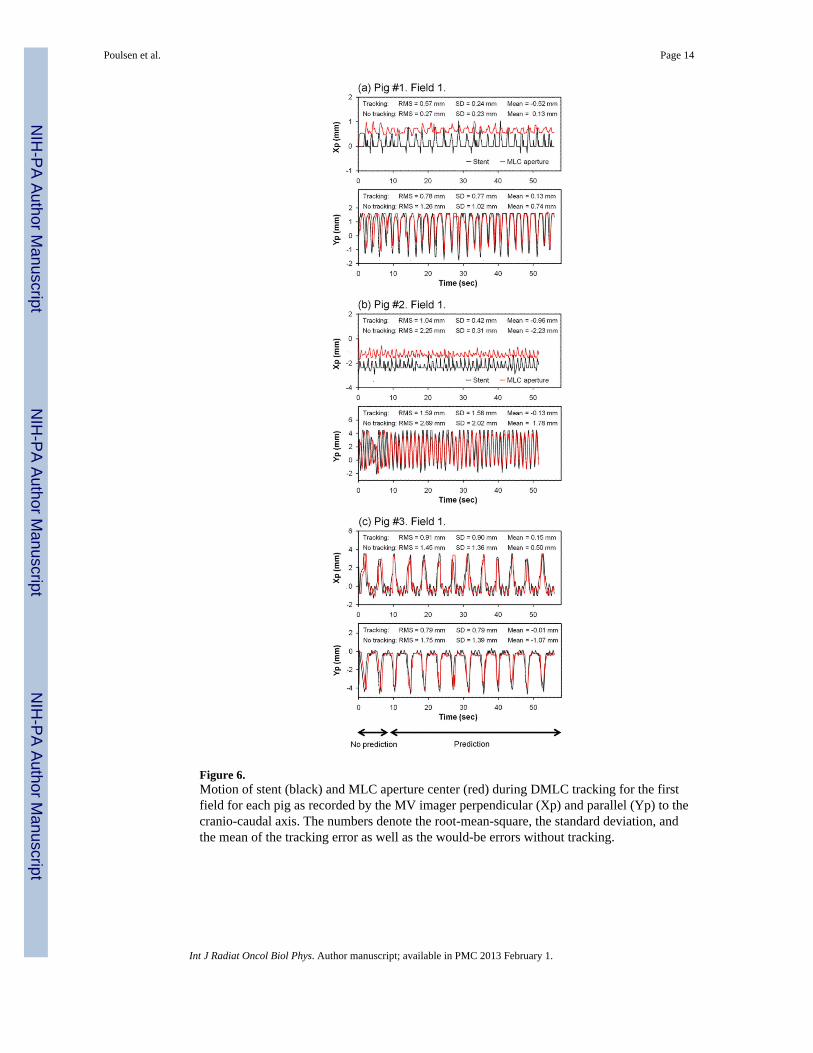
Figure 6.Motion of stent (black) and MLC aperture center (red) during DMLC tracking for the firstfield for each pig as recorded by the MV imager perpendicular (Xp) and parallel (Yp) to thecranio-caudal axis. The numbers denote the root-mean-square, the standard deviation, andthe mean of the tracking error as well as the would-be errors without tracking.
Poulsen et al. Page 14
Int J Radiat Oncol Biol Phys. Author manuscript; available in PMC 2013 February 1.
NIH
-PA Author Manuscript
NIH
-PA Author Manuscript
NIH
-PA Author Manuscript

Figure 7.Root-mean-square MLC position error for the 11 fields with reliable stent segmentation incase of no tracking (black); as observed during DMLC tracking (red); with tracking whenexcluding the first sixty MV images with no prediction (green); and with tracking ifcorrection for gantry sag and non-reproducible MV imager positioning had been made(blue). Xp and Yp denote the MV imager directions perpendicular and parallel to the cranio-caudal axis, respectively.
Poulsen et al. Page 15
Int J Radiat Oncol Biol Phys. Author manuscript; available in PMC 2013 February 1.
NIH
-PA Author Manuscript
NIH
-PA Author Manuscript
NIH
-PA Author Manuscript

Figure 8.Experimental mean tracking error versus the expected error stemming from gantry sag andirreproducible imager positioning for the 11 fields with reliable stent segmentationperpendicular (Xp) and parallel (Yp) to the cranio-caudal axis. A line with unity slope isshown for reference.
Poulsen et al. Page 16
Int J Radiat Oncol Biol Phys. Author manuscript; available in PMC 2013 February 1.
NIH
-PA Author Manuscript
NIH
-PA Author Manuscript
NIH
-PA Author Manuscript

NIH
-PA Author Manuscript
NIH
-PA Author Manuscript
NIH
-PA Author Manuscript
Poulsen et al. Page 17
Tabl
e 1
Sum
mar
y of
trac
king
err
ors o
bser
ved
in M
V im
ages
per
pend
icul
ar (X
p) a
nd p
aral
lel (
Yp)
to th
e cr
anio
-cau
dal a
xis.
All
units
are
mm
.
Mot
ion
com
pens
atio
nM
ean
rms e
rror
MΣ
σ2.
5Σ+0
.7σ
Xp
Yp
Xp
Yp
Xp
Yp
Xp
Yp
Xp
Yp
With
out t
rack
ing
1.6
1.9
0.1
0.3
1.7
1.4
0.8
1.4
4.9
4.5
Trac
king
, all
MV
imag
es0.
81.
1−0.5
−0.4
0.5
0.4
0.5
1.1
1.5
1.6
Trac
king
, exc
ludi
ng p
redi
ctio
n tra
inin
g0.
80.
9−0.5
−0.4
0.5
0.4
0.5
0.8
1.5
1.5
Trac
king
, sag
& im
ager
pos
. cor
rect
ion
0.5
0.8
−0.06
−0.05
0.2
0.2
0.5
0.8
0.9
1.0
Int J Radiat Oncol Biol Phys. Author manuscript; available in PMC 2013 February 1.