
MC50 Integrator Guide - Ganeo
196
MC50 Integrator Guide
-
Upload
khangminh22 -
Category
Documents
-
view
3 -
download
0
Transcript of MC50 Integrator Guide - Ganeo

MC50Integrator Guide


MC50 Integrator Guide
72-68196-02
Revision A
March 2005

© 2004-2005 by Symbol Technologies, Inc. All rights reserved.
No part of this publication may be reproduced or used in any form, or by any electrical or mechanical means, without permission in writing from Symbol. This includes electronic or mechanical means, such as photocopying, recording, or information storage and retrieval systems. The material in this manual is subject to change without notice.
The software is provided strictly on an “as is” basis. All software, including firmware, furnished to the user is on a licensed basis. Symbol grants to the user a non-transferable and non-exclusive license to use each software or firmware program delivered hereunder (licensed program). Except as noted below, such license may not be assigned, sublicensed, or otherwise transferred by the user without prior written consent of Symbol. No right to copy a licensed program in whole or in part is granted, except as permitted under copyright law. The user shall not modify, merge, or incorporate any form or portion of a licensed program with other program material, create a derivative work from a licensed program, or use a licensed program in a network without written permission from Symbol. The user agrees to maintain Symbol’s copyright notice on the licensed programs delivered hereunder, and to include the same on any authorized copies it makes, in whole or in part. The user agrees not to decompile, disassemble, decode, or reverse engineer any licensed program delivered to the user or any portion thereof.
Symbol reserves the right to make changes to any software or product to improve reliability, function, or design.
Symbol does not assume any product liability arising out of, or in connection with, the application or use of any product, circuit, or application described herein.
No license is granted, either expressly or by implication, estoppel, or otherwise under any Symbol Technologies, Inc., intellectual property rights. An implied license only exists for equipment, circuits, and subsystems contained in Symbol products.
Symbol, Spectrum One, and Spectrum24 are registered trademarks of Symbol Technologies, Inc. Bluetooth is a registered trademark of Bluetooth SIG. Microsoft, Windows and ActiveSync are either registered trademarks or trademarks of Microsoft Corporation. Other product names mentioned in this manual may be trademarks or registered trademarks of their respective companies and are hereby acknowledged.
Symbol Technologies, Inc.One Symbol PlazaHoltsville, New York 11742-1300http://www.symbol.com
Patents
This product is covered by one or more of the patents listed on the website: www.symbol.com/patents

Contents
About This Guide
Introduction . . . . . . . . . . . . . . . . . . . . . . . . . . . . . . . . . . . . . . . . . . . . . . . . . . . . . . . . . . . . . . . . . . . . . . . . . . . . . xiDocumentation Set . . . . . . . . . . . . . . . . . . . . . . . . . . . . . . . . . . . . . . . . . . . . . . . . . . . . . . . . . . . . . . . . . . . . xi
Configurations . . . . . . . . . . . . . . . . . . . . . . . . . . . . . . . . . . . . . . . . . . . . . . . . . . . . . . . . . . . . . . . . . . . . . . . . . . . xiiChapter Descriptions . . . . . . . . . . . . . . . . . . . . . . . . . . . . . . . . . . . . . . . . . . . . . . . . . . . . . . . . . . . . . . . . . . . . . . xiiNotational Conventions . . . . . . . . . . . . . . . . . . . . . . . . . . . . . . . . . . . . . . . . . . . . . . . . . . . . . . . . . . . . . . . . . . . . xiiRelated Documents and Software . . . . . . . . . . . . . . . . . . . . . . . . . . . . . . . . . . . . . . . . . . . . . . . . . . . . . . . . . . . . xiiiService Information . . . . . . . . . . . . . . . . . . . . . . . . . . . . . . . . . . . . . . . . . . . . . . . . . . . . . . . . . . . . . . . . . . . . . . . xiii
Symbol Support Center . . . . . . . . . . . . . . . . . . . . . . . . . . . . . . . . . . . . . . . . . . . . . . . . . . . . . . . . . . . . . . . . . . . . . . . . . . xiv
Chapter 1. Getting StartedIntroduction . . . . . . . . . . . . . . . . . . . . . . . . . . . . . . . . . . . . . . . . . . . . . . . . . . . . . . . . . . . . . . . . . . . . . . . . . . . . 1-3Unpacking the Mobile Computer . . . . . . . . . . . . . . . . . . . . . . . . . . . . . . . . . . . . . . . . . . . . . . . . . . . . . . . . . . . . . 1-3Accessories . . . . . . . . . . . . . . . . . . . . . . . . . . . . . . . . . . . . . . . . . . . . . . . . . . . . . . . . . . . . . . . . . . . . . . . . . . . . . 1-4MC50 Demo Application . . . . . . . . . . . . . . . . . . . . . . . . . . . . . . . . . . . . . . . . . . . . . . . . . . . . . . . . . . . . . . . . . . . 1-4Getting Started. . . . . . . . . . . . . . . . . . . . . . . . . . . . . . . . . . . . . . . . . . . . . . . . . . . . . . . . . . . . . . . . . . . . . . . . . . . 1-4Installing and Removing the Main Battery . . . . . . . . . . . . . . . . . . . . . . . . . . . . . . . . . . . . . . . . . . . . . . . . . . . . . 1-5
Installing the Main Battery . . . . . . . . . . . . . . . . . . . . . . . . . . . . . . . . . . . . . . . . . . . . . . . . . . . . . . . . . . . . .1-5Removing the Main Battery . . . . . . . . . . . . . . . . . . . . . . . . . . . . . . . . . . . . . . . . . . . . . . . . . . . . . . . . . . . . . 1-5
Charging the Battery . . . . . . . . . . . . . . . . . . . . . . . . . . . . . . . . . . . . . . . . . . . . . . . . . . . . . . . . . . . . . . . . . . . . . . 1-6Charging the Main Battery and Memory Backup Battery . . . . . . . . . . . . . . . . . . . . . . . . . . . . . . . . . . . . . . 1-6Calibrating the Battery . . . . . . . . . . . . . . . . . . . . . . . . . . . . . . . . . . . . . . . . . . . . . . . . . . . . . . . . . . . . . . . . . 1-7Charging Spare Batteries . . . . . . . . . . . . . . . . . . . . . . . . . . . . . . . . . . . . . . . . . . . . . . . . . . . . . . . . . . . . . . . 1-7
Resetting the Mobile Computer. . . . . . . . . . . . . . . . . . . . . . . . . . . . . . . . . . . . . . . . . . . . . . . . . . . . . . . . . . . . . .1-7Performing a Warm Boot . . . . . . . . . . . . . . . . . . . . . . . . . . . . . . . . . . . . . . . . . . . . . . . . . . . . . . . . . . . . . . . 1-7

MC50 Integrator Guideiv
Performing a Cold Boot. . . . . . . . . . . . . . . . . . . . . . . . . . . . . . . . . . . . . . . . . . . . . . . . . . . . . . . . . . . . . . . . .1-8Locking the Keypad. . . . . . . . . . . . . . . . . . . . . . . . . . . . . . . . . . . . . . . . . . . . . . . . . . . . . . . . . . . . . . . . . . . . . . . .1-8
Chapter 2. AccessoriesIntroduction. . . . . . . . . . . . . . . . . . . . . . . . . . . . . . . . . . . . . . . . . . . . . . . . . . . . . . . . . . . . . . . . . . . . . . . . . . . . . 2- 3
Cradles . . . . . . . . . . . . . . . . . . . . . . . . . . . . . . . . . . . . . . . . . . . . . . . . . . . . . . . . . . . . . . . . . . . . . . . . . . . . .2-3Miscellaneous . . . . . . . . . . . . . . . . . . . . . . . . . . . . . . . . . . . . . . . . . . . . . . . . . . . . . . . . . . . . . . . . . . . . . . .2-3Snap-on Modules . . . . . . . . . . . . . . . . . . . . . . . . . . . . . . . . . . . . . . . . . . . . . . . . . . . . . . . . . . . . . . . . . . . . .2-3
Headset. . . . . . . . . . . . . . . . . . . . . . . . . . . . . . . . . . . . . . . . . . . . . . . . . . . . . . . . . . . . . . . . . . . . . . . . . . . . . . . . .2-4Multi Media Card (MMC) / Secure Device (SD) Card . . . . . . . . . . . . . . . . . . . . . . . . . . . . . . . . . . . . . . . . . . . . .2-4Single Slot USB Cradle . . . . . . . . . . . . . . . . . . . . . . . . . . . . . . . . . . . . . . . . . . . . . . . . . . . . . . . . . . . . . . . . . . . . .2-5
Setup. . . . . . . . . . . . . . . . . . . . . . . . . . . . . . . . . . . . . . . . . . . . . . . . . . . . . . . . . . . . . . . . . . . . . . . . . . . . . . .2-5Charging the Mobile Computer Battery . . . . . . . . . . . . . . . . . . . . . . . . . . . . . . . . . . . . . . . . . . . . . . . . . . . .2-6Charging the Spare Battery . . . . . . . . . . . . . . . . . . . . . . . . . . . . . . . . . . . . . . . . . . . . . . . . . . . . . . . . . . . . .2-6Battery Charging Indicators . . . . . . . . . . . . . . . . . . . . . . . . . . . . . . . . . . . . . . . . . . . . . . . . . . . . . . . . . . . . .2-6
Four Slot USB Cradle . . . . . . . . . . . . . . . . . . . . . . . . . . . . . . . . . . . . . . . . . . . . . . . . . . . . . . . . . . . . . . . . . . . . . .2-8Setup. . . . . . . . . . . . . . . . . . . . . . . . . . . . . . . . . . . . . . . . . . . . . . . . . . . . . . . . . . . . . . . . . . . . . . . . . . . . . . .2-8UConnect . . . . . . . . . . . . . . . . . . . . . . . . . . . . . . . . . . . . . . . . . . . . . . . . . . . . . . . . . . . . . . . . . . . . . . . . . . .2-9Charging . . . . . . . . . . . . . . . . . . . . . . . . . . . . . . . . . . . . . . . . . . . . . . . . . . . . . . . . . . . . . . . . . . . . . . . . . . .2-12Battery Charging Indicators . . . . . . . . . . . . . . . . . . . . . . . . . . . . . . . . . . . . . . . . . . . . . . . . . . . . . . . . . . . .2-12
Four Slot Ethernet Cradle . . . . . . . . . . . . . . . . . . . . . . . . . . . . . . . . . . . . . . . . . . . . . . . . . . . . . . . . . . . . . . . . . .2-13Setup. . . . . . . . . . . . . . . . . . . . . . . . . . . . . . . . . . . . . . . . . . . . . . . . . . . . . . . . . . . . . . . . . . . . . . . . . . . . . .2-13Daisychaining Cradles . . . . . . . . . . . . . . . . . . . . . . . . . . . . . . . . . . . . . . . . . . . . . . . . . . . . . . . . . . . . . . . .2-14Ethernet Cradle Drivers . . . . . . . . . . . . . . . . . . . . . . . . . . . . . . . . . . . . . . . . . . . . . . . . . . . . . . . . . . . . . . .2-15Charging . . . . . . . . . . . . . . . . . . . . . . . . . . . . . . . . . . . . . . . . . . . . . . . . . . . . . . . . . . . . . . . . . . . . . . . . . . .2-16Battery Charging Indicators . . . . . . . . . . . . . . . . . . . . . . . . . . . . . . . . . . . . . . . . . . . . . . . . . . . . . . . . . . . .2-16
Four Slot Spare Battery Charger. . . . . . . . . . . . . . . . . . . . . . . . . . . . . . . . . . . . . . . . . . . . . . . . . . . . . . . . . . . . .2-17Spare Battery Charging . . . . . . . . . . . . . . . . . . . . . . . . . . . . . . . . . . . . . . . . . . . . . . . . . . . . . . . . . . . . . . .2-17Battery Charging Indicators . . . . . . . . . . . . . . . . . . . . . . . . . . . . . . . . . . . . . . . . . . . . . . . . . . . . . . . . . . . .2-17
Magnetic Stripe Reader (MSR) . . . . . . . . . . . . . . . . . . . . . . . . . . . . . . . . . . . . . . . . . . . . . . . . . . . . . . . . . . . . .2-18Attaching and Removing . . . . . . . . . . . . . . . . . . . . . . . . . . . . . . . . . . . . . . . . . . . . . . . . . . . . . . . . . . . . . .2-18Using the MSR . . . . . . . . . . . . . . . . . . . . . . . . . . . . . . . . . . . . . . . . . . . . . . . . . . . . . . . . . . . . . . . . . . . . . .2-18
Cable Adapter Module . . . . . . . . . . . . . . . . . . . . . . . . . . . . . . . . . . . . . . . . . . . . . . . . . . . . . . . . . . . . . . . . . . . .2-20Attaching and Removing . . . . . . . . . . . . . . . . . . . . . . . . . . . . . . . . . . . . . . . . . . . . . . . . . . . . . . . . . . . . . .2-20Battery Charging. . . . . . . . . . . . . . . . . . . . . . . . . . . . . . . . . . . . . . . . . . . . . . . . . . . . . . . . . . . . . . . . . . . . .2-21USB Connection . . . . . . . . . . . . . . . . . . . . . . . . . . . . . . . . . . . . . . . . . . . . . . . . . . . . . . . . . . . . . . . . . . . . .2-21
Universal Battery Charger (UBC) Adapter . . . . . . . . . . . . . . . . . . . . . . . . . . . . . . . . . . . . . . . . . . . . . . . . . . . . .2-23Setup. . . . . . . . . . . . . . . . . . . . . . . . . . . . . . . . . . . . . . . . . . . . . . . . . . . . . . . . . . . . . . . . . . . . . . . . . . . . . .2-23Battery Insertion and Removal . . . . . . . . . . . . . . . . . . . . . . . . . . . . . . . . . . . . . . . . . . . . . . . . . . . . . . . . . .2-24Battery Charging Indicators . . . . . . . . . . . . . . . . . . . . . . . . . . . . . . . . . . . . . . . . . . . . . . . . . . . . . . . . . . . .2-24
Chapter 3. ActiveSyncIntroduction. . . . . . . . . . . . . . . . . . . . . . . . . . . . . . . . . . . . . . . . . . . . . . . . . . . . . . . . . . . . . . . . . . . . . . . . . . . . . 3-3Installing ActiveSync . . . . . . . . . . . . . . . . . . . . . . . . . . . . . . . . . . . . . . . . . . . . . . . . . . . . . . . . . . . . . . . . . . . . . .3-3Setting Up an ActiveSync Connection on the Host Computer . . . . . . . . . . . . . . . . . . . . . . . . . . . . . . . . . . . . . . .3-3Setting Up an ActiveSync Connection on the Mobile Computer . . . . . . . . . . . . . . . . . . . . . . . . . . . . . . . . . . . . .3-5Setting up a Partnership . . . . . . . . . . . . . . . . . . . . . . . . . . . . . . . . . . . . . . . . . . . . . . . . . . . . . . . . . . . . . . . . . . . .3-7

Contents v
Chapter 4. Software Installation on Development PCIntroduction. . . . . . . . . . . . . . . . . . . . . . . . . . . . . . . . . . . . . . . . . . . . . . . . . . . . . . . . . . . . . . . . . . . . . . . . . . . . . 4-3Required System Configurations . . . . . . . . . . . . . . . . . . . . . . . . . . . . . . . . . . . . . . . . . . . . . . . . . . . . . . . . . . . . .4-3DCP for MC50 . . . . . . . . . . . . . . . . . . . . . . . . . . . . . . . . . . . . . . . . . . . . . . . . . . . . . . . . . . . . . . . . . . . . . . . . . . . .4-3
Installing . . . . . . . . . . . . . . . . . . . . . . . . . . . . . . . . . . . . . . . . . . . . . . . . . . . . . . . . . . . . . . . . . . . . . . . . . . . .4-3Components . . . . . . . . . . . . . . . . . . . . . . . . . . . . . . . . . . . . . . . . . . . . . . . . . . . . . . . . . . . . . . . . . . . . . . . . .4-4
SMDK for eVC4. . . . . . . . . . . . . . . . . . . . . . . . . . . . . . . . . . . . . . . . . . . . . . . . . . . . . . . . . . . . . . . . . . . . . . . . . . .4-4Installing . . . . . . . . . . . . . . . . . . . . . . . . . . . . . . . . . . . . . . . . . . . . . . . . . . . . . . . . . . . . . . . . . . . . . . . . . . . .4-4SMDK for eVC4 Contents and Locations . . . . . . . . . . . . . . . . . . . . . . . . . . . . . . . . . . . . . . . . . . . . . . . . . . .4-5
Installing Other Development Software. . . . . . . . . . . . . . . . . . . . . . . . . . . . . . . . . . . . . . . . . . . . . . . . . . . . . . . .4-5Software Updates. . . . . . . . . . . . . . . . . . . . . . . . . . . . . . . . . . . . . . . . . . . . . . . . . . . . . . . . . . . . . . . . . . . . . . . . .4-5
Chapter 5. Software Installation on Mobile ComputerIntroduction. . . . . . . . . . . . . . . . . . . . . . . . . . . . . . . . . . . . . . . . . . . . . . . . . . . . . . . . . . . . . . . . . . . . . . . . . . . . . 5-3Downloading Files Using ActiveSync. . . . . . . . . . . . . . . . . . . . . . . . . . . . . . . . . . . . . . . . . . . . . . . . . . . . . . . . . .5-3Downloading Files Using an MMC/SD Card . . . . . . . . . . . . . . . . . . . . . . . . . . . . . . . . . . . . . . . . . . . . . . . . . . . .5-4Adding Programs . . . . . . . . . . . . . . . . . . . . . . . . . . . . . . . . . . . . . . . . . . . . . . . . . . . . . . . . . . . . . . . . . . . . . . . . .5-4
Adding a Program from the Internet. . . . . . . . . . . . . . . . . . . . . . . . . . . . . . . . . . . . . . . . . . . . . . . . . . . . . . .5-5Other Downloading Methods . . . . . . . . . . . . . . . . . . . . . . . . . . . . . . . . . . . . . . . . . . . . . . . . . . . . . . . . . . . . . . . .5-5
Chapter 6. Creating and Loading Hex ImagesIntroduction. . . . . . . . . . . . . . . . . . . . . . . . . . . . . . . . . . . . . . . . . . . . . . . . . . . . . . . . . . . . . . . . . . . . . . . . . . . . . 6-3Starting Terminal Configuration Manager . . . . . . . . . . . . . . . . . . . . . . . . . . . . . . . . . . . . . . . . . . . . . . . . . . . . . .6-4Defining Script Properties . . . . . . . . . . . . . . . . . . . . . . . . . . . . . . . . . . . . . . . . . . . . . . . . . . . . . . . . . . . . . . . . . .6-7Creating the Script for the Hex Image . . . . . . . . . . . . . . . . . . . . . . . . . . . . . . . . . . . . . . . . . . . . . . . . . . . . . . . . .6-8
Opening a New or Existing Script . . . . . . . . . . . . . . . . . . . . . . . . . . . . . . . . . . . . . . . . . . . . . . . . . . . . . . . .6-8Updating TCM 1.X Scripts . . . . . . . . . . . . . . . . . . . . . . . . . . . . . . . . . . . . . . . . . . . . . . . . . . . . . . . . . . . . . .6-8Copying Components to the Script. . . . . . . . . . . . . . . . . . . . . . . . . . . . . . . . . . . . . . . . . . . . . . . . . . . . . . . .6-8Saving the Script . . . . . . . . . . . . . . . . . . . . . . . . . . . . . . . . . . . . . . . . . . . . . . . . . . . . . . . . . . . . . . . . . . . . .6-8
Building the Image . . . . . . . . . . . . . . . . . . . . . . . . . . . . . . . . . . . . . . . . . . . . . . . . . . . . . . . . . . . . . . . . . . . . . . . .6-9Downloading the Hex Image using a USB Connection . . . . . . . . . . . . . . . . . . . . . . . . . . . . . . . . . . . . . . . . . . .6-10Downloading the Hex Image using an MMC/SD Card . . . . . . . . . . . . . . . . . . . . . . . . . . . . . . . . . . . . . . . . . . .6-13TCM Error Messages . . . . . . . . . . . . . . . . . . . . . . . . . . . . . . . . . . . . . . . . . . . . . . . . . . . . . . . . . . . . . . . . . . . . .6-15IPL Error Detection . . . . . . . . . . . . . . . . . . . . . . . . . . . . . . . . . . . . . . . . . . . . . . . . . . . . . . . . . . . . . . . . . . . . . . .6-16Flash Storage . . . . . . . . . . . . . . . . . . . . . . . . . . . . . . . . . . . . . . . . . . . . . . . . . . . . . . . . . . . . . . . . . . . . . . . . . . .6-18
FFS Partitions . . . . . . . . . . . . . . . . . . . . . . . . . . . . . . . . . . . . . . . . . . . . . . . . . . . . . . . . . . . . . . . . . . . . . . .6-18Working with FFS Partitions. . . . . . . . . . . . . . . . . . . . . . . . . . . . . . . . . . . . . . . . . . . . . . . . . . . . . . . . . . . .6-18Non-FFS Partitions . . . . . . . . . . . . . . . . . . . . . . . . . . . . . . . . . . . . . . . . . . . . . . . . . . . . . . . . . . . . . . . . . . .6-19Downloading Partitions to the Mobile Computer . . . . . . . . . . . . . . . . . . . . . . . . . . . . . . . . . . . . . . . . . . .6-19
IPL . . . . . . . . . . . . . . . . . . . . . . . . . . . . . . . . . . . . . . . . . . . . . . . . . . . . . . . . . . . . . . . . . . . . . . . . . . . . . . . . . . . .6-20Partition Update vs. File Update. . . . . . . . . . . . . . . . . . . . . . . . . . . . . . . . . . . . . . . . . . . . . . . . . . . . . . . . .6-20Upgrade Requirements. . . . . . . . . . . . . . . . . . . . . . . . . . . . . . . . . . . . . . . . . . . . . . . . . . . . . . . . . . . . . . . .6-20
Chapter 7. Symbol Configuration Manager (SCM)Introduction. . . . . . . . . . . . . . . . . . . . . . . . . . . . . . . . . . . . . . . . . . . . . . . . . . . . . . . . . . . . . . . . . . . . . . . . . . . . . 7-3File Types . . . . . . . . . . . . . . . . . . . . . . . . . . . . . . . . . . . . . . . . . . . . . . . . . . . . . . . . . . . . . . . . . . . . . . . . . . . . . . .7-3User Interface . . . . . . . . . . . . . . . . . . . . . . . . . . . . . . . . . . . . . . . . . . . . . . . . . . . . . . . . . . . . . . . . . . . . . . . . . . . .7-3

MC50 Integrator Guidevi
Menu Functions . . . . . . . . . . . . . . . . . . . . . . . . . . . . . . . . . . . . . . . . . . . . . . . . . . . . . . . . . . . . . . . . . . . . . .7-4Parameter State Indicators. . . . . . . . . . . . . . . . . . . . . . . . . . . . . . . . . . . . . . . . . . . . . . . . . . . . . . . . . . . . . .7-4Window Status Bar . . . . . . . . . . . . . . . . . . . . . . . . . . . . . . . . . . . . . . . . . . . . . . . . . . . . . . . . . . . . . . . . . . .7-5
Registry File Deployment . . . . . . . . . . . . . . . . . . . . . . . . . . . . . . . . . . . . . . . . . . . . . . . . . . . . . . . . . . . . . . . . . . .7-5
Chapter 8. WLAN ConfigurationIntroduction. . . . . . . . . . . . . . . . . . . . . . . . . . . . . . . . . . . . . . . . . . . . . . . . . . . . . . . . . . . . . . . . . . . . . . . . . . . . . 8-3Mobile Companion . . . . . . . . . . . . . . . . . . . . . . . . . . . . . . . . . . . . . . . . . . . . . . . . . . . . . . . . . . . . . . . . . . . . . . . .8-4
Finding WLANs. . . . . . . . . . . . . . . . . . . . . . . . . . . . . . . . . . . . . . . . . . . . . . . . . . . . . . . . . . . . . . . . . . . . . . .8-4Status . . . . . . . . . . . . . . . . . . . . . . . . . . . . . . . . . . . . . . . . . . . . . . . . . . . . . . . . . . . . . . . . . . . . . . . . . . . . .8-15Setting Options . . . . . . . . . . . . . . . . . . . . . . . . . . . . . . . . . . . . . . . . . . . . . . . . . . . . . . . . . . . . . . . . . . . . . .8-19Changing Profiles . . . . . . . . . . . . . . . . . . . . . . . . . . . . . . . . . . . . . . . . . . . . . . . . . . . . . . . . . . . . . . . . . . . .8-21
Using LEAP for Wireless Network Security . . . . . . . . . . . . . . . . . . . . . . . . . . . . . . . . . . . . . . . . . . . . . . . . . . . .8-22Configuring Advanced Password Options . . . . . . . . . . . . . . . . . . . . . . . . . . . . . . . . . . . . . . . . . . . . . . . . .8-22
Enterprise Level Wi-Fi Protected Access . . . . . . . . . . . . . . . . . . . . . . . . . . . . . . . . . . . . . . . . . . . . . . . . . . . . . .8-24AEGIS Security Client . . . . . . . . . . . . . . . . . . . . . . . . . . . . . . . . . . . . . . . . . . . . . . . . . . . . . . . . . . . . . . . . .8-24
Configuring the DS (11 Mb) Radio Using a Registry File . . . . . . . . . . . . . . . . . . . . . . . . . . . . . . . . . . . . . . . . . .8-24Connecting to the Internet on a Wireless Network . . . . . . . . . . . . . . . . . . . . . . . . . . . . . . . . . . . . . . . . . . . . . .8-25
Chapter 9. AirBEAM SmartIntroduction. . . . . . . . . . . . . . . . . . . . . . . . . . . . . . . . . . . . . . . . . . . . . . . . . . . . . . . . . . . . . . . . . . . . . . . . . . . . . 9-3AirBEAM Package Builder . . . . . . . . . . . . . . . . . . . . . . . . . . . . . . . . . . . . . . . . . . . . . . . . . . . . . . . . . . . . . . . . . .9-3AirBEAM Smart Client . . . . . . . . . . . . . . . . . . . . . . . . . . . . . . . . . . . . . . . . . . . . . . . . . . . . . . . . . . . . . . . . . . . . .9-3
AirBEAM License . . . . . . . . . . . . . . . . . . . . . . . . . . . . . . . . . . . . . . . . . . . . . . . . . . . . . . . . . . . . . . . . . . . . .9-3Configuring the AirBEAM Smart Client . . . . . . . . . . . . . . . . . . . . . . . . . . . . . . . . . . . . . . . . . . . . . . . . . . . .9-4Synchronizing with the Server . . . . . . . . . . . . . . . . . . . . . . . . . . . . . . . . . . . . . . . . . . . . . . . . . . . . . . . . . . .9-8
AirBEAM Staging . . . . . . . . . . . . . . . . . . . . . . . . . . . . . . . . . . . . . . . . . . . . . . . . . . . . . . . . . . . . . . . . . . . . . . . . .9-8
Chapter 10. Rapid Deployment ClientIntroduction. . . . . . . . . . . . . . . . . . . . . . . . . . . . . . . . . . . . . . . . . . . . . . . . . . . . . . . . . . . . . . . . . . . . . . . . . . . . 10-3Rapid Deployment Window . . . . . . . . . . . . . . . . . . . . . . . . . . . . . . . . . . . . . . . . . . . . . . . . . . . . . . . . . . . . . . . .10-3Scanning RD Bar Codes . . . . . . . . . . . . . . . . . . . . . . . . . . . . . . . . . . . . . . . . . . . . . . . . . . . . . . . . . . . . . . . . . . .10-5
Chapter 11. Maintenance & TroubleshootingIntroduction. . . . . . . . . . . . . . . . . . . . . . . . . . . . . . . . . . . . . . . . . . . . . . . . . . . . . . . . . . . . . . . . . . . . . . . . . . . . 11-3Maintaining the Mobile Computer . . . . . . . . . . . . . . . . . . . . . . . . . . . . . . . . . . . . . . . . . . . . . . . . . . . . . . . . . . .11-3Troubleshooting . . . . . . . . . . . . . . . . . . . . . . . . . . . . . . . . . . . . . . . . . . . . . . . . . . . . . . . . . . . . . . . . . . . . . . . . .11-4
Mobile Computer . . . . . . . . . . . . . . . . . . . . . . . . . . . . . . . . . . . . . . . . . . . . . . . . . . . . . . . . . . . . . . . . . . . .11-4Four Slot Spare Battery Charger. . . . . . . . . . . . . . . . . . . . . . . . . . . . . . . . . . . . . . . . . . . . . . . . . . . . . . . . .11-5Single Slot USB Cradle . . . . . . . . . . . . . . . . . . . . . . . . . . . . . . . . . . . . . . . . . . . . . . . . . . . . . . . . . . . . . . . .11-6Four Slot USB and Ethernet Cradles. . . . . . . . . . . . . . . . . . . . . . . . . . . . . . . . . . . . . . . . . . . . . . . . . . . . . .11-7Cable Adapter Module . . . . . . . . . . . . . . . . . . . . . . . . . . . . . . . . . . . . . . . . . . . . . . . . . . . . . . . . . . . . . . . .11-8Magnetic Stripe Reader . . . . . . . . . . . . . . . . . . . . . . . . . . . . . . . . . . . . . . . . . . . . . . . . . . . . . . . . . . . . . . .11-8
Appendix A. Specifications
Technical Specifications. . . . . . . . . . . . . . . . . . . . . . . . . . . . . . . . . . . . . . . . . . . . . . . . . . . . . . . . . . . . . . . . . . . A-3

Contents vii
MC50 Accessory Specifications. . . . . . . . . . . . . . . . . . . . . . . . . . . . . . . . . . . . . . . . . . . . . . . . . . . . . . . . . A-6COM Port Definitions . . . . . . . . . . . . . . . . . . . . . . . . . . . . . . . . . . . . . . . . . . . . . . . . . . . . . . . . . . . . . . . . . . . . A-10Pin-Outs . . . . . . . . . . . . . . . . . . . . . . . . . . . . . . . . . . . . . . . . . . . . . . . . . . . . . . . . . . . . . . . . . . . . . . . . . . . . . . A-11
Appendix B. Keypad Maps
Introduction. . . . . . . . . . . . . . . . . . . . . . . . . . . . . . . . . . . . . . . . . . . . . . . . . . . . . . . . . . . . . . . . . . . . . . . . . . . . . B-3Example . . . . . . . . . . . . . . . . . . . . . . . . . . . . . . . . . . . . . . . . . . . . . . . . . . . . . . . . . . . . . . . . . . . . . . . . . . . B-3
Keypads . . . . . . . . . . . . . . . . . . . . . . . . . . . . . . . . . . . . . . . . . . . . . . . . . . . . . . . . . . . . . . . . . . . . . . . . . . . . . . . B-4
Glossary
Index
Tell Us What You Think...

MC50 Integrator Guideviii

About This Guide
Introduction . . . . . . . . . . . . . . . . . . . . . . . . . . . . . . . . . . . . . . . . . . . . . . . . . . . . . . . . . . . . . . . . . . . . . . . . . . . . . xiDocumentation Set . . . . . . . . . . . . . . . . . . . . . . . . . . . . . . . . . . . . . . . . . . . . . . . . . . . . . . . . . . . . . . . . . . . . xi
Configurations . . . . . . . . . . . . . . . . . . . . . . . . . . . . . . . . . . . . . . . . . . . . . . . . . . . . . . . . . . . . . . . . . . . . . . . . . . . xiiChapter Descriptions . . . . . . . . . . . . . . . . . . . . . . . . . . . . . . . . . . . . . . . . . . . . . . . . . . . . . . . . . . . . . . . . . . . . . . xiiNotational Conventions . . . . . . . . . . . . . . . . . . . . . . . . . . . . . . . . . . . . . . . . . . . . . . . . . . . . . . . . . . . . . . . . . . . . xiiRelated Documents and Software . . . . . . . . . . . . . . . . . . . . . . . . . . . . . . . . . . . . . . . . . . . . . . . . . . . . . . . . . . . . xiiiService Information . . . . . . . . . . . . . . . . . . . . . . . . . . . . . . . . . . . . . . . . . . . . . . . . . . . . . . . . . . . . . . . . . . . . . . . xiii
Symbol Support Center . . . . . . . . . . . . . . . . . . . . . . . . . . . . . . . . . . . . . . . . . . . . . . . . . . . . . . . . . . . . . . . . . . . . . . . . . . xiv

MC50 Integrator Guidex

xi
IntroductionThis Integrator Guide provides information about setting up and configuring MC50 mobile computers and accessories.
Screens and windows pictured in this guide are samples and can differ from actual screens.
Documentation SetThe documentation for the MC50 is divided into guides that provide information for specific user needs.
• Microsoft® Applications User Guide for Symbol Devices - describes how to use Microsoft-developed applications.• Symbol Application Guide - describes how to use Symbol-developed applications.• MC50 User Guide - describes how to use the MC50 mobile computer. Provided on the DCP.• MC50 Integrator Guide - describes how to set up MC50 product accessories and how to install software. Provided on the
DCP.• API Help File - provides API information for writing applications for the MC50.

MC50 Integrator Guidexii
ConfigurationsDepending on device configuration, the MC50 includes the following features:
• OS: Microsoft Windows Mobile 2003 Second Edition for Pocket PC• Memory Configuration: 64 MB ROM/64 MB RAM• Display: 3.5” QVGA transflective color touchscreen• Keypads: Navigation (PDA-style) or QWERTY• Data Capture: 1-dimensional bar code scanning via linear CMOS, 1-dimensional and 2-dimensional bar code imaging, or
image capture via camera• Radio: 802.11b wireless LAN (WLAN).
Chapter DescriptionsTopics covered in this guide are as follows:
• Chapter 1, Getting Started provides information on mobile computer configurations and accessories, charging the battery, and resetting.
• Chapter 2, Accessories describes the accessories available for the mobile computer and how to set up power connections and battery charging capabilities, where applicable.
• Chapter 3, ActiveSync provides instructions on installing ActiveSync and setting up a partnership between the mobile computer and a host computer.
• Chapter 4, Software Installation on Development PC provides instructions for installing the Device Configuration Package (DCP) for MC50 and the SMDK for eVC4 on the host computer.
• Chapter 5, Software Installation on Mobile Computer provides information for downloading software and files to the mobile computer.
• Chapter 6, Creating and Loading Hex Images describes how to install and use the Terminal Configuration Manager (TCM) and Initial Program Loader (IPL) to customize flash file system partitions for the mobile computer.
• Chapter 7, Symbol Configuration Manager (SCM) describes how to use the Symbol Configuration Manager (SCM.exe) utility to create registry files that set configuration parameters on a mobile computer.
• Chapter 8, WLAN Configuration describes how to configure the wireless connection.• Chapter 9, AirBEAM Smart explains how to transfer specially-designed software packages between a host server and
Symbol mobile computers.• Chapter 10, Rapid Deployment Client describes how to use the Rapid Deployment (RD) Client to facilitate software
downloads to a mobile computer from a Mobility Services Platform (MSP) Console’s FTP server.• Chapter 11, Maintenance & Troubleshooting, includes instructions on cleaning and storing the mobile computer, and
provides troubleshooting solutions for potential problems during mobile computer operation.• Appendix A, Specifications includes a table listing the technical specifications for the mobile computer.• Appendix B, Keypad Maps contains keypad maps for keypad configurations.
Notational ConventionsThe following conventions are used in this document:
• “Mobile computer” refers to any Symbol terminal. • Italics are used to highlight the following:
• chapters and sections in this and related documents• dialog box, window and screen names

xiii
• drop-down list and list box names• check box and radio button names• icons on a screen.
• Bold text is used to highlight the following:• key names on a keypad• button names on a screen.
• Bullets (•) indicate:• action items• lists of alternatives• lists of required steps that are not necessarily sequential.
• Sequential lists (e.g., those that describe step-by-step procedures) appear as numbered lists.
Related Documents and SoftwareThe following documents provide more information about the MC50 mobile computers.
• MC50 Quick Start Poster, p/n 72-67793-xx• MC50 Regulatory Guide, p/n 72-67863-xx• MC50 User Guide, p/n 72E-68195-xx• Microsoft® Applications User Guide for Symbol Devices, p/n 72-68197-xx• Symbol Application Guide, p/n 72-65258-xx• Symbol Mobility Developer Kit for eMbedded Visual C++ v4.0 (SMDK for eVC4), available at: http://devzone.symbol.com/• MC50 Device Configuration Package (DCP), available at: http://devzone.symbol.com/.• ActiveSync software, available at: http://www.microsoft.com.
For the latest version of this guide and all guides, go to: http://www.symbol.com/manuals.
Service InformationIf you have a problem with the equipment, contact the Symbol Support Center for your region. See page xiv for contact information. Before calling, have the model number, serial number and several bar code symbols at hand.
Call the Support Center from a phone near the scanning equipment so that the service person can try to talk you through the problem. If the equipment is found to be working properly and the problem is symbol readability, the Support Center will request samples of bar codes for analysis at our plant.
If the problem cannot be solved over the phone, you may need to return the equipment for servicing. If that is necessary, you will be given specific directions.
Symbol Technologies is not responsible for any damages incurred during shipment if the approved shipping container is not used. Shipping the units improperly can possibly void the warranty. If the original shipping container was not kept, contact Symbol to have another sent to you.

MC50 Integrator Guidexiv
Symbol Support CenterFor service information, warranty information or technical assistance contact or call the Symbol Support Center in:
United StatesSymbol Technologies, Inc.One Symbol PlazaHoltsville, New York 11742-13001-800-653-5350
CanadaSymbol Technologies Canada, Inc.5180 Orbitor DriveMississauga, Ontario, Canada L4W 5L91-866-416-8545 (Inside Canada)905-629-7226 (Outside Canada)
United KingdomSymbol TechnologiesSymbol PlaceWinnersh Triangle, Berkshire RG41 5TPUnited Kingdom0800 328 2424 (Inside UK)+44 118 945 7529 (Outside UK)
Asia/PacificSymbol Technologies Asia, Inc. (Singapore Branch)230 Victoria Street #05-07/09Bugis Junction Office TowerSingapore 188024Tel: +65-6796-9600 Fax: +65-6337-6488
AustraliaSymbol Technologies Pty. Ltd.432 St. Kilda RoadMelbourne, Victoria 30041-800-672-906 (Inside Australia)+61-3-9866-6044 (Outside Australia)
Austria/ÖsterreichSymbol Technologies Austria GmbH Prinz-Eugen Strasse 70 / 2.Haus1040 Vienna, Austria01-5055794-0 (Inside Austria)+43-1-5055794-0 (Outside Austria)
Denmark/DanmarkSymbol Technologies ASDr. Neergaardsvej 32970 Hørsholm7020-1718 (Inside Denmark)+45-7020-1718 (Outside Denmark)
Europe/Mid-East Distributor OperationsContact your local distributor or call+44 118 945 7360
Finland/SuomiOy Symbol TechnologiesKaupintie 8 A 6FIN-00440 Helsinki, Finland9 5407 580 (Inside Finland)+358 9 5407 580 (Outside Finland)
FranceSymbol Technologies FranceCentre d'Affaire d'Antony3 Rue de la Renaissance92184 Antony Cedex, France01-40-96-52-21 (Inside France)+33-1-40-96-52-50 (Outside France)
Germany/DeutschlandSymbol Technologies GmbHWaldstrasse 66D-63128 Dietzenbach, Germany6074-49020 (Inside Germany)+49-6074-49020 (Outside Germany)
Italy/ItaliaSymbol Technologies Italia S.R.L.Via Cristoforo Columbo, 4920090 Trezzano S/N NavigiloMilano, Italy2-484441 (Inside Italy)+39-02-484441 (Outside Italy)
Latin America Sales Support2730 University Dr.Coral Springs, FL 33065 USA1-800-347-0178 (Inside United States)+1-954-255-2610 (Outside United States)954-340-9454 (Fax)
Mexico/MéxicoSymbol Technologies Mexico Ltd.Torre PicassoBoulevard Manuel Avila Camacho No 88Lomas de Chapultepec CP 11000Mexico City, DF, Mexico5-520-1835 (Inside Mexico)+52-5-520-1835 (Outside Mexico)
Netherlands/NederlandSymbol TechnologiesKerkplein 2, 7051 CXPostbus 24 7050 AAVarsseveld, Netherlands315-271700 (Inside Netherlands)+31-315-271700 (Outside Netherlands)

xv
If you purchased your Symbol product from a Symbol Business Partner, contact that Business Partner for service.
Norway/NorgeSymbol’s registered and mailing address:Symbol Technologies NorwayHoybratenveien 35 CN-1055 OSLO, Norway
Symbol’s repair depot and shipping address:Symbol Technologies NorwayEnebakkveien 123N-0680 OSLO, Norway
+47 2232 4375
South AfricaSymbol Technologies Africa Inc.Block B2Rutherford Estate1 Scott StreetWaverly 2090 JohannesburgRepublic of South Africa11-809 5311 (Inside South Africa)+27-11-809 5311 (Outside South Africa)
Spain/EspañaSymbol Technologies S.L.Avenida de Bruselas, 22Edificio SauceAlcobendas, Madrid 28108Spain91 324 40 00 (Inside Spain)+34 91 324 40 00 (Outside Spain)Fax: +34.91.324.4010
Sweden/Sverige“Letter” address:Symbol Technologies ABBox 1354S-171 26 SOLNASweden
Visit/shipping address:Symbol Technologies ABSolna Strandväg 78S-171 54 SOLNASweden
Switchboard: 08 445 29 00 (domestic)Call Center: +46 8 445 29 29 (international)Support E-Mail: [email protected]

MC50 Integrator Guidexvi

Getting Started
Introduction . . . . . . . . . . . . . . . . . . . . . . . . . . . . . . . . . . . . . . . . . . . . . . . . . . . . . . . . . . . . . . . . . . . . . . . . . . . . 1-3Unpacking the Mobile Computer . . . . . . . . . . . . . . . . . . . . . . . . . . . . . . . . . . . . . . . . . . . . . . . . . . . . . . . . . . . . . 1-3Accessories . . . . . . . . . . . . . . . . . . . . . . . . . . . . . . . . . . . . . . . . . . . . . . . . . . . . . . . . . . . . . . . . . . . . . . . . . . . . . 1-4MC50 Demo Application . . . . . . . . . . . . . . . . . . . . . . . . . . . . . . . . . . . . . . . . . . . . . . . . . . . . . . . . . . . . . . . . . . . 1-4Getting Started. . . . . . . . . . . . . . . . . . . . . . . . . . . . . . . . . . . . . . . . . . . . . . . . . . . . . . . . . . . . . . . . . . . . . . . . . . . 1-4Installing and Removing the Main Battery . . . . . . . . . . . . . . . . . . . . . . . . . . . . . . . . . . . . . . . . . . . . . . . . . . . . . 1-5
Installing the Main Battery . . . . . . . . . . . . . . . . . . . . . . . . . . . . . . . . . . . . . . . . . . . . . . . . . . . . . . . . . . . . .1-5Removing the Main Battery . . . . . . . . . . . . . . . . . . . . . . . . . . . . . . . . . . . . . . . . . . . . . . . . . . . . . . . . . . . . . 1-5
Charging the Battery . . . . . . . . . . . . . . . . . . . . . . . . . . . . . . . . . . . . . . . . . . . . . . . . . . . . . . . . . . . . . . . . . . . . . . 1-6Charging the Main Battery and Memory Backup Battery . . . . . . . . . . . . . . . . . . . . . . . . . . . . . . . . . . . . . . 1-6Calibrating the Battery . . . . . . . . . . . . . . . . . . . . . . . . . . . . . . . . . . . . . . . . . . . . . . . . . . . . . . . . . . . . . . . . . 1-7Charging Spare Batteries . . . . . . . . . . . . . . . . . . . . . . . . . . . . . . . . . . . . . . . . . . . . . . . . . . . . . . . . . . . . . . . 1-7
Resetting the Mobile Computer. . . . . . . . . . . . . . . . . . . . . . . . . . . . . . . . . . . . . . . . . . . . . . . . . . . . . . . . . . . . . .1-7Performing a Warm Boot . . . . . . . . . . . . . . . . . . . . . . . . . . . . . . . . . . . . . . . . . . . . . . . . . . . . . . . . . . . . . . . 1-7Performing a Cold Boot . . . . . . . . . . . . . . . . . . . . . . . . . . . . . . . . . . . . . . . . . . . . . . . . . . . . . . . . . . . . . . . . 1-8
Locking the Keypad . . . . . . . . . . . . . . . . . . . . . . . . . . . . . . . . . . . . . . . . . . . . . . . . . . . . . . . . . . . . . . . . . . . . . . . 1-8

MC50 Integrator Guide1-2

Getting Started 1-3
IntroductionThis chapter provides information about the mobile computer, accessories, charging the mobile computer, and resetting the mobile computer.
Unpacking the Mobile ComputerCarefully remove all protective material from around the mobile computer and save the shipping container for later storage and shipping. Verify that the equipment listed below is included:
• mobile computer• stylus, in the stylus silo• hand strap• soft case• Regulatory Guide• Quick Start Guide (poster).
Depending on the configuration ordered, the mobile computer package can also include:
• standard or extra capacity battery• AC adaptor• communication/charging cable• power supply• US line cord• headset• desktop cradle.
Inspect the equipment. If any equipment is missing or damaged, contact the Symbol Technologies Support Center immediately. See Service Information on page xiii for contact information.

MC50 Integrator Guide1-4
AccessoriesThe following accessories are available:
MC50 Demo ApplicationThe MC50 includes sample and demo applications to assist in application development.
To access the MC50 Demo, tap Start - MC50 Demo. See the Symbol Application Guide, p/n 72-65258-xx for information on using Symbol applications.
Getting StartedBefore using the mobile computer for the first time:
• install the main battery• charge the main battery and backup battery• start the mobile computer• configure the mobile computer.
Charge the main battery before or after it is installed. Use one of the spare battery chargers to charge the main battery (out of the mobile computer), or one of the cradles to charge the main battery installed in the mobile computer.
Table 1-1. MC50 Accessories
Accessory Description
Single Slot USB Cradle Charges the mobile computer main battery and a spare battery, and synchronizes the mobile computer with a host computer through a USB connection.
Four Slot USB Cradle Charges up to four mobile computers, and synchronizes the mobile computer with a host computer through a USB connection.
Four Slot Ethernet Cradle Charges up to four mobile computers, synchronizes the mobile computer with a host computer through an Ethernet connection, and networks the mobile computer via an Ethernet hub.
Four Slot Spare Battery Charger Charges up to four mobile computer spare batteries.
Magnetic Stripe Reader (MSR) Snaps on to the mobile computer and adds magstripe reading capabilities.
Rigid Carrying Case Provides added protection for the mobile computer.
Headset For audio playback in noisy environments.
Cable Adapter Module (CAM) Snap-on required to connect the following cables to the mobile computer:
AC line cord (country-specific) and power supply Used with the CAM to charge the mobile computer.
Auto charge cable Used with the CAM to charge the mobile computer using a vehicle’s power port.
USB cable Used with the CAM to add USB communication capabilities.
Universal Battery Charger Adapter Adapts the UBC for use with MC50 batteries.
Symbol Mobility Developer Kit for eMbedded Visual C++ v4.0 (SMDK for eVC4)
A development tool used to create native C and C++ applications for all Symbol mobile computers running the Microsoft Windows Mobile 2003 Software for Pocket PCs operating system. Available at http://www.symbol.com/MC50.
Device Configuration Package (DCP) for MC50 A development tool used to create and download hex images that represent flash partitions to the mobile computer. Available at http://www.symbol.com/mc50.

Getting Started 1-5
Installing and Removing the Main Battery
Installing the Main BatteryBefore using the mobile computer, install the battery:
1. If the Battery Lock Switch is not unlocked, use the stylus to slide the switch to the left to unlock it. A red dot appears on the switch.
2. Insert the main battery into the back of the mobile computer as show in Figure 1-1.3. Press the battery down into the battery compartment until the battery release slides into place.
Figure 1-1. Inserting the Battery
Ensure the battery is positioned correctly, placing the battery charging contacts on top of the charging contacts in the battery compartment.
4. Using the stylus, slide the Battery Lock Switch to the right to lock it.
Removing the Main BatteryTo remove the main battery:
1. Press the power button to suspend the mobile computer.2. Using the stylus, slide the Battery Lock Switch to the left to unlock it. A red dot appears on the switch.3. Slide the battery release down, and pull the battery up and out of the mobile computer.
Battery
Battery Release
Battery Lock Switch
Note

MC50 Integrator Guide1-6
Charging the Battery
Charging the Main Battery and Memory Backup BatteryBefore using the mobile computer for the first time, charge the main battery for 24 hours (see Table 1-2 on page 1-7 for charge status indications) using a cradle or the CAM with a charging cable.
The mobile computer is equipped with a memory backup battery which automatically charges from the fully-charged main battery. When the mobile computer is used for the first time, the backup battery requires approximately 24 hours to fully charge. This also applies any time the backup battery is discharged, which occurs when the main battery is removed for several hours. The backup battery retains data in memory for at least 30 minutes when the mobile computer's main battery is removed. When the mobile computer reaches a very low battery state, the combination of main battery and backup battery retains data in memory for at least 72 hours.
Do not remove the main battery within the first 15 hours of use. If the main battery is removed before the backup battery is fully charged, data can be lost.
Use the following accessories to charge batteries:
• Cradles: The mobile computer and spare batteries slip into a cradle for battery charging. For detailed cradle setup and charging procedures see:• Single Slot USB Cradle on page 2-5.• Four Slot USB Cradle on page 2-8• Four Slot Ethernet Cradle on page 2-13.
• Cable Adapter Module (CAM): The CAM snaps on to the mobile computer to provide charging capability, when used with one of the accessory charging cables. For detailed setup and charging procedures see Cable Adapter Module on page 2-20.
• Chargers: The mobile computer’s spare battery charging accessories are used to charge batteries that are removed from the mobile computer. For detailed spare battery charging accessories setup and charging procedures see:• Single Slot USB Cradle on page 2-5• Four Slot Spare Battery Charger on page 2-17• Universal Battery Charger (UBC) Adapter on page 2-23.
To optimize battery life in mobile computers with multiple radios, turn off radios that are not being used via the SetDevicePower() API (see the Windows CE Help File for Symbol Terminals) or via the Control Panel application (tap Start - MC50 - Ctl Panel icon).
To charge the main battery in the mobile computer using a cradle or the CAM with a charging cable:
1. Ensure the accessory used to charge the main battery is connected to the appropriate power source (see Chapter 2, Accessories for setup information).
2. Insert the mobile computer into a cradle or attach the CAM.3. The mobile computer begins charging. The Charge LED is amber while charging, then turns green when fully charged.

Getting Started 1-7
The standard battery fully charges in approximately 3.5 hours and the extended capacity battery fully charges in approximately seven hours.
Calibrating the BatteryThe MC50 battery requires periodic calibration to maintain an accurate calibration of the battery's gas gauge. To calibrate the battery, deplete the battery completely from a full charge condition. Symbol recommends performing this once a week.
Charging Spare BatteriesUse one of the following accessories to charge spare batteries:
• Single Slot USB Cradle• Four Slot Spare Battery Charger• UBC Adapter.
To charge a spare battery:
1. Ensure the accessory used to charge the spare battery is connected to the appropriate power source (see Chapter 2, Accessories for setup information).
2. Insert the spare battery into the accessory’s spare battery charging slot with the charging contacts on the battery aligned with the charging pins in the charging slot, and gently press down on the battery to ensure proper contact.The battery begins charging. The amber charge LED on the accessory lights to show the charge status. See Chapter 2, Accessories for charging indications for the accessory.
In the single slot cradle, the standard battery fully charges in 3.5 hours and the extended capacity battery fully charges in approximately seven hours. Using other accessories, the standard battery fully charges in 2.5 hours and the extended capacity battery fully charges in approximately six hours.
Resetting the Mobile ComputerIf the mobile computer stops responding to input, reset it. There are two reset functions:
• A warm boot restarts the mobile computer by closing all running programs. Perform a warm boot first, as this saves all stored records and entries. If the mobile computer still does not respond, perform a cold boot.
• A cold boot also restarts the mobile computer, but erases all stored records and entries in RAM, and returns formats, preferences, and other settings to the factory default settings. Data saved in flash memory or a memory card is retained.Never perform a cold boot unless a warm boot does not solve the problem.
Performing a Warm BootPress the reset button located below the battery release on the back of the mobile computer.
Table 1-2. Mobile Computer LED Charge Indicators
LED Indication
Green Main battery is fully charged.
Amber Charging main battery.
Flashing Amber Error in charging; check cable connections.
MC50 Integrator Guide1-8
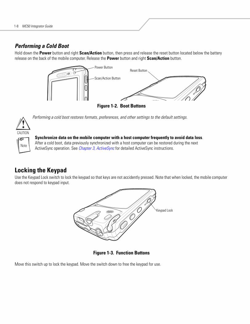
Performing a Cold BootHold down the Power button and right Scan/Action button, then press and release the reset button located below the battery release on the back of the mobile computer. Release the Power button and right Scan/Action button.
Figure 1-2. Boot Buttons
Performing a cold boot restores formats, preferences, and other settings to the default settings.
Synchronize data on the mobile computer with a host computer frequently to avoid data loss. After a cold boot, data previously synchronized with a host computer can be restored during the next ActiveSync operation. See Chapter 3, ActiveSync for detailed ActiveSync instructions.
Locking the KeypadUse the Keypad Lock switch to lock the keypad so that keys are not accidently pressed. Note that when locked, the mobile computer does not respond to keypad input.
Figure 1-3. Function Buttons
Move this switch up to lock the keypad. Move the switch down to free the keypad for use.
Reset ButtonPower Button
Scan/Action Button
Keypad Lock

Accessories
Introduction . . . . . . . . . . . . . . . . . . . . . . . . . . . . . . . . . . . . . . . . . . . . . . . . . . . . . . . . . . . . . . . . . . . . . . . . . . . . 2-3Cradles . . . . . . . . . . . . . . . . . . . . . . . . . . . . . . . . . . . . . . . . . . . . . . . . . . . . . . . . . . . . . . . . . . . . . . . . . . . . . 2-3Miscellaneous . . . . . . . . . . . . . . . . . . . . . . . . . . . . . . . . . . . . . . . . . . . . . . . . . . . . . . . . . . . . . . . . . . . . . . . 2-3Snap-on Modules . . . . . . . . . . . . . . . . . . . . . . . . . . . . . . . . . . . . . . . . . . . . . . . . . . . . . . . . . . . . . . . . . . . . . 2-3
Headset . . . . . . . . . . . . . . . . . . . . . . . . . . . . . . . . . . . . . . . . . . . . . . . . . . . . . . . . . . . . . . . . . . . . . . . . . . . . . . . . 2-4Multi Media Card (MMC) / Secure Device (SD) Card . . . . . . . . . . . . . . . . . . . . . . . . . . . . . . . . . . . . . . . . . . . . . 2-4Single Slot USB Cradle. . . . . . . . . . . . . . . . . . . . . . . . . . . . . . . . . . . . . . . . . . . . . . . . . . . . . . . . . . . . . . . . . . . . . 2-5
Setup . . . . . . . . . . . . . . . . . . . . . . . . . . . . . . . . . . . . . . . . . . . . . . . . . . . . . . . . . . . . . . . . . . . . . . . . . . . . . . 2-5Charging the Mobile Computer Battery . . . . . . . . . . . . . . . . . . . . . . . . . . . . . . . . . . . . . . . . . . . . . . . . . . . . 2-6Charging the Spare Battery . . . . . . . . . . . . . . . . . . . . . . . . . . . . . . . . . . . . . . . . . . . . . . . . . . . . . . . . . . . . .2-6Battery Charging Indicators . . . . . . . . . . . . . . . . . . . . . . . . . . . . . . . . . . . . . . . . . . . . . . . . . . . . . . . . . . . . . 2-6
Four Slot USB Cradle . . . . . . . . . . . . . . . . . . . . . . . . . . . . . . . . . . . . . . . . . . . . . . . . . . . . . . . . . . . . . . . . . . . . . . 2-8Setup . . . . . . . . . . . . . . . . . . . . . . . . . . . . . . . . . . . . . . . . . . . . . . . . . . . . . . . . . . . . . . . . . . . . . . . . . . . . . . 2-8UConnect . . . . . . . . . . . . . . . . . . . . . . . . . . . . . . . . . . . . . . . . . . . . . . . . . . . . . . . . . . . . . . . . . . . . . . . . . . . 2-8Charging . . . . . . . . . . . . . . . . . . . . . . . . . . . . . . . . . . . . . . . . . . . . . . . . . . . . . . . . . . . . . . . . . . . . . . . . . . 2-12Battery Charging Indicators . . . . . . . . . . . . . . . . . . . . . . . . . . . . . . . . . . . . . . . . . . . . . . . . . . . . . . . . . . . . 2-12
Four Slot Ethernet Cradle . . . . . . . . . . . . . . . . . . . . . . . . . . . . . . . . . . . . . . . . . . . . . . . . . . . . . . . . . . . . . . . . . . 2-13Setup . . . . . . . . . . . . . . . . . . . . . . . . . . . . . . . . . . . . . . . . . . . . . . . . . . . . . . . . . . . . . . . . . . . . . . . . . . . . . 2-13Ethernet Cradle Drivers . . . . . . . . . . . . . . . . . . . . . . . . . . . . . . . . . . . . . . . . . . . . . . . . . . . . . . . . . . . . . . . 2-14Charging . . . . . . . . . . . . . . . . . . . . . . . . . . . . . . . . . . . . . . . . . . . . . . . . . . . . . . . . . . . . . . . . . . . . . . . . . . 2-15Battery Charging Indicators . . . . . . . . . . . . . . . . . . . . . . . . . . . . . . . . . . . . . . . . . . . . . . . . . . . . . . . . . . . . 2-15
Four Slot Spare Battery Charger . . . . . . . . . . . . . . . . . . . . . . . . . . . . . . . . . . . . . . . . . . . . . . . . . . . . . . . . . . . .2-16Spare Battery Charging . . . . . . . . . . . . . . . . . . . . . . . . . . . . . . . . . . . . . . . . . . . . . . . . . . . . . . . . . . . . . . . 2-16Battery Charging Indicators . . . . . . . . . . . . . . . . . . . . . . . . . . . . . . . . . . . . . . . . . . . . . . . . . . . . . . . . . . . . 2-16
Magnetic Stripe Reader (MSR) . . . . . . . . . . . . . . . . . . . . . . . . . . . . . . . . . . . . . . . . . . . . . . . . . . . . . . . . . . . . . 2-17Attaching and Removing . . . . . . . . . . . . . . . . . . . . . . . . . . . . . . . . . . . . . . . . . . . . . . . . . . . . . . . . . . . . . . 2-17

MC50 Integrator Guide2-2
Using the MSR . . . . . . . . . . . . . . . . . . . . . . . . . . . . . . . . . . . . . . . . . . . . . . . . . . . . . . . . . . . . . . . . . . . . . .2-17Cable Adapter Module . . . . . . . . . . . . . . . . . . . . . . . . . . . . . . . . . . . . . . . . . . . . . . . . . . . . . . . . . . . . . . . . . . . .2-19
Attaching and Removing . . . . . . . . . . . . . . . . . . . . . . . . . . . . . . . . . . . . . . . . . . . . . . . . . . . . . . . . . . . . . .2-19Battery Charging. . . . . . . . . . . . . . . . . . . . . . . . . . . . . . . . . . . . . . . . . . . . . . . . . . . . . . . . . . . . . . . . . . . . .2-20USB Connection . . . . . . . . . . . . . . . . . . . . . . . . . . . . . . . . . . . . . . . . . . . . . . . . . . . . . . . . . . . . . . . . . . . . .2-20
Universal Battery Charger (UBC) Adapter . . . . . . . . . . . . . . . . . . . . . . . . . . . . . . . . . . . . . . . . . . . . . . . . . . . . .2-22Setup. . . . . . . . . . . . . . . . . . . . . . . . . . . . . . . . . . . . . . . . . . . . . . . . . . . . . . . . . . . . . . . . . . . . . . . . . . . . . .2-22Battery Insertion and Removal . . . . . . . . . . . . . . . . . . . . . . . . . . . . . . . . . . . . . . . . . . . . . . . . . . . . . . . . . .2-22Battery Charging Indicators . . . . . . . . . . . . . . . . . . . . . . . . . . . . . . . . . . . . . . . . . . . . . . . . . . . . . . . . . . . .2-23

Accessories 2-3
IntroductionMC50 accessories provide a variety of product support capabilities. Accessories include cradles, Magnetic Stripe Reader (MSR) and Cable Adapter Module (CAM) snap-ons, four-slot spare battery charger, headset, Multimedia Card (MMC), Secure Device (SD) card, and Universal Battery Charger (UBC) adapter.
Cradles• Single Slot USB cradle charges the mobile computer main battery and a spare battery. It also synchronizes the mobile
computer with a host computer through a USB connection.• Four Slot USB cradle charges the mobile computer main battery. It also synchronizes the mobile computer with a host
computer through a USB connection.• Four Slot Ethernet cradle charges the mobile computer main battery and connects the mobile computer with an Ethernet
network.
Miscellaneous• Four Slot Spare Battery Charger charges up to four mobile computer spare batteries.• Headset can be used in noisy environments.• Multimedia Card or Secure Digital (SD) Card provides secondary non-volatile storage.• UBC adapter adapts the UBC for use with MC50 batteries.
Snap-on Modules• MSR snaps on to the mobile computer and adds magstripe read capabilities. • CAM snaps on to the mobile computer and connects cables to the mobile computer for battery charging and synchronizing
the mobile computer with a host computer through a USB connection.
The CAM uses the cables listed below:
• AC line cord (country-specific) and power supply, charges the mobile computer.• Auto charge cable, charges the mobile computer using a vehicle’s cigarette lighter.• USB cable, adds USB communication capabilities.

MC50 Integrator Guide2-4
HeadsetUse the headset to communicate via Voice-over-IP (VoIP) or for audio playback. To connect the headset, remove the plug from the headset jack at the top of the mobile computer and insert the headset connector. Contact a Symbol representative for compatible headsets.
Figure 2-1. Headset Connection
Multi Media Card (MMC) / Secure Device (SD) CardThe MMC/SD card slot provides secondary non-volatile storage. The slot is located at the top of the mobile computer (see Figure 2-2).
A variety of third-party cards can be used in the mobile computer for storage, Bluetooth connection, Voice-over-IP, and other functions. Refer to the documentation provided with the card for more information, and follow the manufacturer’s recommendations for use.
SD cards are inter-operable with MMC cards; both can be used in MC50 mobile computers.
Follow proper ESD precautions to avoid damaging the MMC/SD. Proper ESD precautions include, but are not limited to, working on an ESD mat and ensuring that the operator is properly grounded.
To insert the MMC/SD:
1. Power off the mobile computer.2. Remove the card cover at the top of the mobile computer by removing the screw and lifting the cover out of the slot.3. If a card is already installed, press the card in to release it, then remove it.4. Insert the new card with the card contacts aligning with the contacts in the MMC/SD housing, until you feel a click.
Figure 2-2. MMC/SD Card Insertion
5. Replace the housing cover and secure with the screw.

Accessories 2-5
Single Slot USB CradleThis section describes how to set up and use a Single Slot USB cradle with the mobile computer. For USB communication setup procedures see Chapter 3, ActiveSync.
The Single Slot USB Cradle:
• Provides 5.4 VDC power for operating the mobile computer.• Synchronizes information between the mobile computer and a host computer. (With customized or third party software, it
can also synchronize the mobile computer with corporate databases.) See Chapter 3, ActiveSync for information on setting up a partnership between the mobile computer and a host computer.
• Charges the mobile computer’s battery.• Charges a spare battery.
Use only a Symbol-approved power supply (p/n 50-14000-147) output rated 5.4 Vdc and minimum 3A. The power supply is certified to EN60950 with SELV outputs. Use of alternative power supply will invalidate any approval given to this device and may be dangerous.
Hinweis: Benutzen Sie nur eine von Symbol Technologies genehmigte Stromversorgung (Teilenr. 50-14000-147) mit einer Ausgangsleistung von 5.4 V (Gleichstrom) und mindestens 3A. Die Stromversorgung ist nach EN60950 für die Verwendung in SELV-Stromkreisen zertifiziert. Bei Verwendung eines anderen Netzteils werden alle für das Gerät gewährten Genehmigungen außer Kraft gesetzt, und der Betrieb kann gefährlich sein.
SetupThe cradle requires a dedicated port on the host.
Figure 2-3. Single Slot Cradle Power and USB Connections
Power Supply
USB Port
Power Port

MC50 Integrator Guide2-6
Charging the Mobile Computer Battery Connect the cradle to power, or to the host computer using the USB connection.
Insert the mobile computer into the mobile computer slot to begin charging.
Figure 2-4. Mobile Computer Battery Charging
Charging the Spare Battery
Figure 2-5. Spare Battery Charging
Battery Charging IndicatorsThe Single Slot USB Cradle charges the mobile computer’s main battery and a spare battery simultaneously.
The mobile computer’s charge LED indicates the status of the battery charging in the mobile computer. See Table 1-2 on page 1-7 for charging status indications.
The spare battery charging LED on the cradle indicates the status of the spare battery charging in the cradle. See Table 2-1 for charging status indications.
The standard battery fully charges in approximately 3.5 hours and the extended capacity battery fully charges in approximately seven hours.
Battery Charging LED
Spare Battery
Spare BatteryCharging Well
Spare BatteryCharging LED

Accessories 2-7
Table 2-1. Spare Battery LED Charging Indicators
Spare Battery LED(on cradle) Indication
Off No spare battery in slot; spare battery not placed correctly; cradle is not powered.
Solid Amber Spare battery is charging.
Flashing Amber Error in charging; check placement of spare battery.
Solid Green Spare battery is fully charged.

MC50 Integrator Guide2-8
Four Slot USB CradleThis section describes how to set up and use a Four Slot USB cradle with the mobile computer. For cradle communication setup procedures see, Chapter 3, ActiveSync.
The Four Slot USB cradle:
• Provides 12 VDC power for operating the mobile computer.• Enables data communication between the mobile computer (up to four) and a host computer, using a USB connection.• Synchronizes information between the mobile computer and a host computer. (With customized or third party software, it
can also synchronize the mobile computer with corporate databases.)• Simultaneously charges up to four batteries in the mobile computer.
Use only a Symbol-approved power supply (p/n 50-14000-148) output rated 12 Vdc and minimum 3.33A. The power supply is certified to EN60950 with SELV outputs. Use of alternative power supply will invalidate any approval given to this device and may be dangerous.
Hinweis: Benutzen Sie nur eine von Symbol Technologies genehmigte Stromversorgung (Teilenr. 50-14000-148) mit einer Ausgangsleistung von 12 V (Gleichstrom) und mindestens 3.33A. Die Stromversorgung ist nach EN60950 für die Verwendung in SELV-Stromkreisen zertifiziert. Bei Verwendung eines anderen Netzteils werden alle für das Gerät gewährten Genehmigungen außer Kraft gesetzt, und der Betrieb kann gefährlich sein.
SetupConnect the USB cradle to a power source and to a USB port on the host device.
Figure 2-6. Four Slot USB Cradle Connection
Power Port
USB Port

Accessories 2-9
UConnectUConnect software enables automatic synchronization of every mobile computer inserted in the Four-Slot USB cradle.
Installing UConnectInstall UConnect in one of two ways:
• Download individual UConnect files to the Application partition of the mobile computer.• Copy a .CAB file to the mobile computer and launch the file.
To install UConnect via downloading individual files:
1. Download the UConnect files from the Symbol website, http://devzone.symbol.com, to the host computer.a. On http://devzone.symbol.com, select Developer Downloads and sign in.b. Select PocketPC/WinCE/CE.Net Platform.c. Select MC50 (Windows Mobile 2003 for Pocket PC.d. Select Four-Slot USB Cradle Drivers for MC50w vx.x, then download the .zip file to the development computer.
2. Unzip the file. Copy the files to the Application partition of the mobile computer. See Chapter 6, Creating and Loading Hex Images.
3. Perform a hard reset.The Connect.reg file contains information on customizing UConnect's startup settings.
To install UConnect via the .CAB file:
1. Download the UConnect .CAB file from the Symbol website, http://devzone.symbol.com, to the host computer.2. Copy the file from the host computer to the mobile computer. See Downloading Files Using ActiveSync on page 5-3. 3. On the mobile computer, navigate to the .CAB file and double-tap the file.4. Follow the screen prompts to install.
With this method, the .CAB file does not install the .cpy and .reg files.
Once installed, UConnect launches automatically upon mobile computer startup. Each mobile computer must first form an ActiveSync partnership with a host computer for UConnect to successfully manage synchronization.
Configuring UConnectTo customize default settings for UConnect, create a .reg file that overrides UConnect’s initial default settings. Refer to UConnect.reg, included with UConnect, for information on setting custom hard reset and default settings.
To customize UConnect temporarily (until the next hard reset):
MC50 Integrator Guide2-10
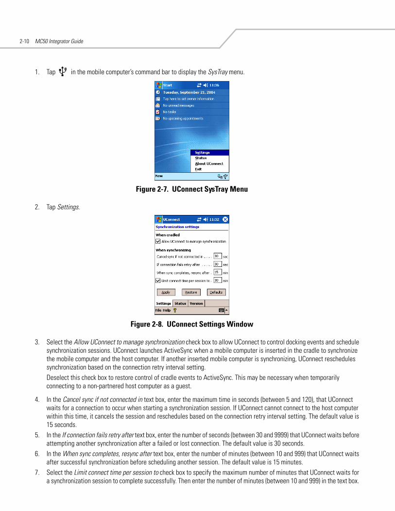
1. Tap in the mobile computer’s command bar to display the SysTray menu.
Figure 2-7. UConnect SysTray Menu
2. Tap Settings.
Figure 2-8. UConnect Settings Window
3. Select the Allow UConnect to manage synchronization check box to allow UConnect to control docking events and schedule synchronization sessions. UConnect launches ActiveSync when a mobile computer is inserted in the cradle to synchronize the mobile computer and the host computer. If another inserted mobile computer is synchronizing, UConnect reschedules synchronization based on the connection retry interval setting.Deselect this check box to restore control of cradle events to ActiveSync. This may be necessary when temporarily connecting to a non-partnered host computer as a guest.
4. In the Cancel sync if not connected in text box, enter the maximum time in seconds (between 5 and 120), that UConnect waits for a connection to occur when starting a synchronization session. If UConnect cannot connect to the host computer within this time, it cancels the session and reschedules based on the connection retry interval setting. The default value is 15 seconds.
5. In the If connection fails retry after text box, enter the number of seconds (between 30 and 9999) that UConnect waits before attempting another synchronization after a failed or lost connection. The default value is 30 seconds.
6. In the When sync completes, resync after text box, enter the number of minutes (between 10 and 999) that UConnect waits after successful synchronization before scheduling another session. The default value is 15 minutes.
7. Select the Limit connect time per session to check box to specify the maximum number of minutes that UConnect waits for a synchronization session to complete successfully. Then enter the number of minutes (between 10 and 999) in the text box.

Accessories 2-11
The default value is enabled, 30 minutes.
If UConnect does not receive a synchronization complete notification from ActiveSync within this time, UConnect disconnects from the host computer to allow recovery in instances where ActiveSync on the host computer or mobile computer cannot complete synchronization.
8. Tap Apply to apply UConnect setting changes. Tap Restore to discard UConnect setting changes and return to the previous settings. Tap Defaults to restore the default settings. Then tap Apply to apply the default settings.
Manually SynchronizingTo synchronize a mobile computer immediately without waiting for a scheduled synchronization, tap File - Sync Now. Note that this option is not active if the mobile computer is not in the cradle, or if synchronization is already in progress.
Closing UConnectTo hide the UConnect user interface without exiting UConnect, tap .
To exit UConnect and transfer control of docking events and synchronization to ActiveSync, tap File - Exit.
UConnect StatusTo view the status of UConnect events, tap - Status. The Status window displays the following information.
Figure 2-9. UConnect Status Window
• The Dock status: field indicates the current docked status of the mobile computer.• The Last sync time: field indicates the date and time the last synchronization session started. If UConnect has not performed
synchronization, None appears. Use this field to determine if successful synchronization occurred since the last time the mobile computer was docked.
• The Last sync status: field indicates the status of the most recent or currently active synchronization session. Possible values are: • Successful: The last synchronization session completed successfully. • Waiting for connection: Synchronization started and UConnect is waiting for the connection with the host to complete. • In progress: Synchronization started and UConnect is waiting for a synchronization complete notification from
ActiveSync. • Failed: Cable detached: Synchronization failed because the mobile computer is not inserted or the USB cable is detached. • Failed: No connection: UConnect could not establish a connection to the host computer.

MC50 Integrator Guide2-12
• Failed: Connection lost: Connection to the host was lost before synchronization completed. • Failed: Connect time exceeded: Synchronization did not complete within the maximum time allowed per session. • Failed: No reason: Synchronization failed for an unknown reason.
• The Next sync time: field indicates the date and time of the next scheduled synchronization session. If UConnect is disabled, the mobile computer is not inserted, or a session is in progress, N/A appears.
• The synchronization history field displays information about docking events and synchronization session status. This field can list up to 100 lines of synchronization history, and can be used to view the status of previous synchronization sessions.
• Tap Clear to erase the contents of the synchronization history list box.
Charging Insert the mobile computer into a slot to begin charging.
Figure 2-10. Mobile Computer Battery Charging
Battery Charging IndicatorsThe mobile computer’s charge LED shows the status of the battery charging in the mobile computer. See Table 1-2 on page 1-7 for charging status indications.
The standard battery fully charges in approximately 3.5 hours and the extended capacity battery fully charges in approximately seven hours.

Accessories 2-13
Four Slot Ethernet CradleThis section describes how to set up and use a Four Slot Ethernet cradle with the mobile computer. For cradle communication setup procedures see, Chapter 3, ActiveSync.
The Four Slot Ethernet cradle:
• Provides 12 VDC power for operating the mobile computer.• Enables data communication between the mobile computer (up to four) and a host computer, using an Ethernet connection.• Synchronizes information between the mobile computer and a host computer. • Connects the mobile computer (up to four) to an Ethernet network.• Simultaneously charges up to four batteries in the mobile computer.
Use only a Symbol-approved power supply (p/n 50-14000-148) output rated 12 Vdc and minimum 3.33A. The power supply is certified to EN60950 with SELV outputs. Use of alternative power supply will invalidate any approval given to this device and may be dangerous.
Hinweis: Benutzen Sie nur eine von Symbol Technologies genehmigte Stromversorgung (Teilenr. 50-14000-148) mit einer Ausgangsleistung von 12 V (Gleichstrom) und mindestens 3.33A. Die Stromversorgung ist nach EN60950 für die Verwendung in SELV-Stromkreisen zertifiziert. Bei Verwendung eines anderen Netzteils werden alle für das Gerät gewährten Genehmigungen außer Kraft gesetzt, und der Betrieb kann gefährlich sein.
SetupConnect the Ethernet cradle to a power source and to an Ethernet hub or a port on the host device.
Figure 2-11. Four Slot Ethernet Cradle Connection
Power Port
Ethernet Port 1
Ethernet HubConnection

MC50 Integrator Guide2-14
Daisychaining CradlesDaisychain up to four Ethernet cradles to connect several cradles to an Ethernet network.
To daisychain more than one cradle:
1. Connect power to each cradle to daisychain, as shown in Setup on page 2-13. 2. Connect an Ethernet cable to Port 1 of the first cradle as shown in Setup on page 2-13. 3. Connect a second Ethernet cable between Port 2 of the first cradle, and Port 1 of the second.4. Connect up to two more cradles as described in Step 3.
Figure 2-12. Daisychaining Four Slot Ethernet Cradles
Bandwidth Considerations when DaisychainingEach cradle added to the daisychain impacts the bandwidth provided to the inserted mobile computers, particularly when the mobile computers attempt to send and receive at data rates that exceed the bandwidth provided to the chain (typically 100 Mbps). If a mobile computer in a daisychained cradle does not use its bandwidth, that bandwidth is allocated to other inserted mobile computers.
Table 2-2 shows available bandwidth, based on 100 Mpbs, for the maximum number of daisychained cradles, with each attempting transmission at the maximum data rate.
Table 2-2. Daisychaining Bandwidth
Daisychained CradlesBandwidth Provided to Cradle
(Mbit/sec)Inserted Mobile Computer’s Share of
Bandwidth
Cradle 1 100,000,000 20,000,000
Cradle 2 20,000,000 4,000,000
Cradle 3 4,000,000 800,000
Cradle 4 800,000 160,000
Cradle 5 160,000 32,000
Cradle 6 32,000 6,400
Cradle 7 6,400 1,280
Ethernet Port 1
Ethernet Port 2

Accessories 2-15
Ethernet Cradle DriversInstall the Ethernet Cradle Drivers to enable the MC50 device to use the Four Slot Ethernet cradle.
Installing the Ethernet Cradle DriversInstall the drivers in one of two ways:
• Download driver files to the mobile computer’s Platform folder.• Copy a .CAB file to the mobile computer and launch the file.
To install the drivers via downloading individual files:
1. Download the Ethernet Cradle Drivers files from the Symbol website, http://devzone.symbol.com, to the host computer:a. On http://devzone.symbol.com, select Developer Downloads and sign in.b. Select PocketPC/WinCE/CE.Net Platform.c. Select MC50 (Windows Mobile 2003 for Pocket PC).d. Select Ethernet Cradle Drivers for MC50w vx.x, then download the .zip file to the development computer.
2. Unzip the file. Copy the files from the installation Platform folder to the mobile computer’s Platform folder. See Downloading Files Using ActiveSync on page 5-3.
3. Perform a hard reset.
To install the drivers via the .CAB file:
1. Download the Ethernet Cradle Drivers files from the Symbol website, http://devzone.symbol.com, to the host computer (see the previous instructions).
2. Copy the file USBOTG.MC50.CAB to the mobile computer. See Downloading Files Using ActiveSync on page 5-3.3. On the mobile computer, navigate to the USBOTG.MC50.CAB file and double-tap the file. 4. When the .CAB file installation completes, soft reset the mobile computer.

MC50 Integrator Guide2-16
Charging Insert the mobile computer into a slot to begin charging.
Figure 2-13. Mobile Computer Battery Charging
Battery Charging IndicatorsThe mobile computer’s charge LED shows the status of the battery charging in the mobile computer. See Table 1-2 on page 1-7 for charging status indications.
The standard battery fully charges in approximately 3.5 hours and the extended capacity battery fully charges in approximately seven hours.

Accessories 2-17
Four Slot Spare Battery ChargerThis section describes how to set up and use the Four Slot Spare Battery Charger to charge up to four MC50 spare batteries.
Use only a Symbol-approved power supply (p/n 50-14000-148) output rated 12 Vdc and minimum 3.33A. The power supply is certified to EN60950 with SELV outputs. Use of alternative power supply will invalidate any approval given to this device and may be dangerous.
Hinweis: Benutzen Sie nur eine von Symbol Technologies genehmigte Stromversorgung (Teilenr. 50-14000-148) mit einer Ausgangsleistung von 12 V (Gleichstrom) und mindestens 3.33A. Die Stromversorgung ist nach EN60950 für die Verwendung in SELV-Stromkreisen zertifiziert. Bei Verwendung eines anderen Netzteils werden alle für das Gerät gewährten Genehmigungen außer Kraft gesetzt, und der Betrieb kann gefährlich sein.
Spare Battery Charging 1. Connect the charger to a power source.2. Insert the spare battery into a spare battery charging well and gently press down on the battery to ensure proper contact.
Figure 2-14. Four Slot Spare Battery Charger
Battery Charging IndicatorsAn amber LED is provided for each battery charging well. See Table 2-3 for charging status indications. The standard battery fully charges in approximately 2.5 hours and the extended capacity battery fully charges in approximately six hours.
Table 2-3. Spare Battery LED Charging Indicators
LED Indication
Off No spare battery in slot; spare battery not placed correctly; cradle is not powered.
Fast Blinking Amber Error in charging; check placement of spare battery.
Slow Blinking Amber Spare battery is charging.
Solid Amber Charging complete.
Power Port
Spare BatteryCharging LEDs (4)
Spare Battery
Spare BatteryCharging Well (4)

MC50 Integrator Guide2-18
Magnetic Stripe Reader (MSR)This section describes how to set up and use the snap-on MSR with the mobile computer. The MSR snaps on to the bottom of the mobile computer and can be easily removed when not in use.
When attached to the mobile computer, the MSR allows the mobile computer to capture data from magnetic stripe cards. To download MSR data capture software, visit http://devzone.symbol.com.
Attaching and RemovingTo attach, slide the MSR onto the bottom of the mobile computer and secure by snapping the arms into the mobile computer housing.
Figure 2-15. MSR Installation
To remove the MSR open the arms and pull the MSR from the mobile computer.
Using the MSR The MSR3000 sample application illustrates how an application should handle MSR inputs (refer to Symbol Applications User’s Guide).
To use the MSR:
1. Attach the MSR to the mobile computer.2. Power on the mobile computer.3. Tap Start - MC50 Demo - Test Apps - MSR MC50 or MSR Cameo to start the sample application.
Card Reader Slot
Arms

Accessories 2-19
4. Swipe the magnetic stripe card through the MSR, with the magnetic stripe on the card facing down. Swipe the card in either direction, from left to right or from right to left. For best results, gently press down on the card while swiping to ensure contact with the bottom of the reader.
Figure 2-16. Magnetic Stripe Card Swiping

MC50 Integrator Guide2-20
Cable Adapter ModuleThis section describes how to set up and use the snap-on CAM with the mobile computer. The CAM snaps on to the bottom of the mobile computer and can be easily removed when not in use.
Figure 2-17. Cable Adapter Module
When attached to the mobile computer, the CAM:
• Provides power for operating the mobile computer, with the appropriate power connection.• Provides Ethernet connection through the Ethernet port for communication with an Ethernet device, such as a host computer
or Ethernet hub. For communication setup procedures, see Chapter 3, ActiveSync. • Charges the mobile computer’s battery, when used with the appropriate power supply.
Use only a Symbol-approved power supply (p/n 50-14000-147) output rated 5.4 Vdc and minimum 3A. The power supply is certified to EN60950 with SELV outputs. Use of alternative power supply will invalidate any approval given to this device and may be dangerous.
Hinweis: Benutzen Sie nur eine von Symbol Technologies genehmigte Stromversorgung (Teilenr. 50-14000-147) mit einer Ausgangsleistung von 5.4 V (Gleichstrom) und mindestens 3A. Die Stromversorgung ist nach EN60950 für die Verwendung in SELV-Stromkreisen zertifiziert. Bei Verwendung eines anderen Netzteils werden alle für das Gerät gewährten Genehmigungen außer Kraft gesetzt, und der Betrieb kann gefährlich sein.
Attaching and RemovingTo attach, slide the CAM onto the bottom of the mobile computer, until it snaps into place.
Figure 2-18. CAM Installation
To remove the CAM pull the CAM from the mobile computer.
Power Port Communications Port

Accessories 2-21
Remove the CAM from the bottom of the mobile computer before using a cradle for charging and communication.
Battery Charging To charge the mobile computer’s battery through the CAM, attach the CAM to the mobile computer, then connect the power supply to the CAM. The mobile computer begins charging.
Figure 2-19. CAM Power Connection
The mobile computer’s charge LED shows the status of the battery charging in the mobile computer. See Table 1-2 on page 1-7 for charging status indications. The standard battery fully charges in approximately 3.5 hours and the extended capacity battery fully charges in approximately seven hours.
USB ConnectionThe CAM can connect to and communicate with a USB device, such as a host computer, through its data port. See Chapter 3, ActiveSync for the host computer communication setup procedure.
To connect the CAM to a USB device, connect one end of the data cable to the data port on the CAM and the other end to the USB port on the device.

MC50 Integrator Guide2-22
Figure 2-20. CAM USB Connection
To DeviceUSB Port
Data Port

Accessories 2-23
Universal Battery Charger (UBC) AdapterThis section describes how to use the UBC adapter to charge a spare battery.
Use the UBC with a power supply as a standalone spare battery charger, or with the four station UBC2000 to simultaneously charge up to four spare batteries. For additional information about the UBC2000, see the UBC 2000 Universal Battery Charger Product Guide (p/n 70-33188-xx).
Use only a Symbol-approved power supply (p/n 50-14000-147) output rated 5.4 Vdc and minimum 3A. The power supply is certified to EN60950 with SELV outputs. Use of alternative power supply will invalidate any approval given to this device and may be dangerous.
Hinweis: Benutzen Sie nur eine von Symbol Technologies genehmigte Stromversorgung (Teilenr. 50-14000-147) mit einer Ausgangsleistung von 5.4 V (Gleichstrom) und mindestens 3A. Die Stromversorgung ist nach EN60950 für die Verwendung in SELV-Stromkreisen zertifiziert. Bei Verwendung eines anderen Netzteils werden alle für das Gerät gewährten Genehmigungen außer Kraft gesetzt, und der Betrieb kann gefährlich sein.
Setup
Figure 2-21. UBC Adapter Power Connection
Power Supply
AC Line Cord
Power Port

MC50 Integrator Guide2-24
Battery Insertion and RemovalInsert the battery into the battery well with the charging contacts on the battery aligning with the charging pins on the adapter, and gently press down on the battery to ensure proper contact.
To remove the battery, press the battery release and lift battery out of the well.
Figure 2-22. UBC Adapter
Battery Charging IndicatorsTo charge a spare battery using the UBC adapter, connect the power supply to the UBC (see Figure 2-21), then insert the spare battery. The spare battery begins charging.
The UBC’s charge LEDs show the status of the battery charging in the adapter. Table 2-4 shows battery charging status indications. The standard battery fully charges in approximately 2.5 hours and the extended capacity battery fully charges in approximately six hours.
Figure 2-23. UBC Adapter LEDs
REA
DY
CH
AR
GIN
G o
r ST
AN
DB
Y o
r FA
ULT
(Gre
en)
(Flas
hing
Yello
w)
(Sol
id Ye
llow
)
(Flas
hing
Yello
w)
POWER
READY
CHARGING or STANDBY or FAULT
(Green)
(Flashing Yellow)(Solid Yellow) (Flashing Yellow)
UBC Adapter
Battery Release
Battery
Battery Well
POWER
READY
CHARGING or STANDBY or FAULT
(Green)
(Flashing Yellow)(Solid Yellow) (Flashing Yellow)

Accessories 2-25
Table 2-4. UBC Adapter Charge LED Status Indications
LED Indication Description
POWER Red Power is connected to the UBC Adapter.
READY Green Charging complete.
CHARGING orSTANDBY orFAULT
Yellow Normal charge.
Flashing Yellow The battery was deeply discharged and is being trickle charged to bring the voltage up to the operating level. After operating level voltage is achieved the battery charges normally.
Flashing Yellow Charging error, check placement of mobile computer/spare battery.

MC50 Integrator Guide2-26

ActiveSync
Introduction . . . . . . . . . . . . . . . . . . . . . . . . . . . . . . . . . . . . . . . . . . . . . . . . . . . . . . . . . . . . . . . . . . . . . . . . . . . . 3-3Installing ActiveSync . . . . . . . . . . . . . . . . . . . . . . . . . . . . . . . . . . . . . . . . . . . . . . . . . . . . . . . . . . . . . . . . . . . . . . 3-3Setting Up an ActiveSync Connection on the Host Computer. . . . . . . . . . . . . . . . . . . . . . . . . . . . . . . . . . . . . . . 3-3Setting Up an ActiveSync Connection on the Mobile Computer. . . . . . . . . . . . . . . . . . . . . . . . . . . . . . . . . . . . . 3-5Setting up a Partnership. . . . . . . . . . . . . . . . . . . . . . . . . . . . . . . . . . . . . . . . . . . . . . . . . . . . . . . . . . . . . . . . . . . . 3-7

MC50 Integrator Guide3-2

ActiveSync 3-3
IntroductionTo communicate with various host devices, install Microsoft ActiveSync (version 3.7 or higher) on the host computer. Use ActiveSync to synchronize information on the mobile computer with information on the host computer. Changes made on the mobile computer or host computer appear in both places after synchronization.
ActiveSync software:
• Allows working with mobile computer-compatible host applications on the host computer. ActiveSync replicates data from the mobile computer so the host application can view, enter, and modify data on the mobile computer.
• Synchronizes files between the mobile computer and host computer, converting the files to the correct format.• Backs up the data stored on the mobile computer. Synchronization is a one-step procedure that ensures the data is always
safe and up-to-date.• Copies (rather than synchronizes) files between the mobile computer and host computer.• Controls when synchronization occurs by selecting a synchronization mode, e.g., set to synchronize continually while the
mobile computer is connected to the host computer, or set to only synchronize on command.• Selects the types of information to synchronize and control how much data is synchronized.
Installing ActiveSyncTo install ActiveSync on the host computer, download the latest version of the software from the Microsoft web site athttp://www.microsoft.com. Refer to the installation and RAS instructions included with the ActiveSync software.
Microsoft recommends installing ActiveSync on the host computer before connecting the mobile computer.
Setting Up an ActiveSync Connection on the Host Computer 1. Select Start - Programs - Microsoft ActiveSync on the host computer.
Figure 3-1. ActiveSync Connected Window
Assign each mobile computer a unique device name. Do not try to synchronize more than one mobile computer to the same name. See the Microsoft Mobile 2003 for Pocket PCs User Guide (p/n 72E-68197-xx) for instructions on changing the device name.

MC50 Integrator Guide3-4
2. In the ActiveSync window, select File - Connection Settings. The Connection Settings window appears.
Figure 3-2. Connection Settings Window
3. Select the appropriate check box for the type of connection used.4. Select the Show status icon in Taskbar check box.5. Select OK to save any changes made.

ActiveSync 3-5
Setting Up an ActiveSync Connection on the Mobile Computer1. On the mobile computer tap Start - ActiveSync to display the ActiveSync window.
Figure 3-3. ActiveSync Window
2. Tap Tools - Options to display the PC Synchronization window - PC tab.
Figure 3-4. PC Synchronization Window - PC Tab
3. Tap Options to display the PC Synchronization Options window.
Figure 3-5. PC Synchronization Options Window

MC50 Integrator Guide3-6
4. Select the Enable PC sync using this connection: check box.5. Select the connection (e.g., USB) for synchronization from the drop-down list. The default connection for synchronization is
USB. 6. Select the Maintain connection radio button.7. Tap ok to exit the PC Synchronization Options window and tap ok to exit the PC Synchronization window.

ActiveSync 3-7
Setting up a PartnershipAfter installing ActiveSync, the ActiveSync Setup Wizard sets up a partnership to synchronize information between the mobile computer and host computer, and customizes synchronization settings.
To set up a partnership:
1. Select Start - Programs - Microsoft ActiveSync - File - Get Connected.
Figure 3-6. Get Connected Window
2. Connect the communication accessory to the host computer and to the appropriate power source (see Chapter 2, Accessories for connection information).
The accessory requires a dedicated port. It cannot share a port with any other device. Refer to the host computer user manual supplied to locate the USB ports.
3. Connect the mobile computer to the accessory.4. Power on the mobile computer.5. On the host computer, select Next in the Get Connected window. The host computer and the mobile computer attempt to
synchronize. The New Partnership window appears.
Figure 3-7. New Partnership Window

MC50 Integrator Guide3-8
6. Click the Standard partnership radio button, then select Next. The New Partnership/Specify how to synchronize data window appears.
Figure 3-8. How to Sync Window
7. Click the Synchronize with this desktop computer radio button and select Next. The New Partnership/Name your Device window appears.
Figure 3-9. Name your Device Window

ActiveSync 3-9
8. Enter a name for the connected device and select Next. The New Partnership/Select Number of Partnerships window appears.
Figure 3-10. Select Number of Partnerships Window
9. Click the Yes, I want to synchronize with only this computer radio button, then select Next. The New Partnership/Select Synchronization Settings window appears.
Figure 3-11. Select Synchronization Settings Window
10. To synchronize a particular type of information, select its check box. To stop synchronization of that information, clear its check box.

MC50 Integrator Guide3-10
11. Select Next. The New Partnership/Setup Complete window appears.
Figure 3-12. Setup Complete Window
12. Select Finish. During the first synchronization, information stored on the host computer is copied to the mobile computer. When the copy is complete and all data is synchronized, disconnect the mobile computer from the host computer if desired.
After creating a partnership between the host computer and mobile computer, synchronization occurs automatically.
For more information about using ActiveSync, start ActiveSync on the host computer and see ActiveSync Help.
Software Installation on Development PC
Introduction . . . . . . . . . . . . . . . . . . . . . . . . . . . . . . . . . . . . . . . . . . . . . . . . . . . . . . . . . . . . . . . . . . . . . . . . . . . . 4-3Required System Configurations . . . . . . . . . . . . . . . . . . . . . . . . . . . . . . . . . . . . . . . . . . . . . . . . . . . . . . . . . . . . .4-3DCP for MC50. . . . . . . . . . . . . . . . . . . . . . . . . . . . . . . . . . . . . . . . . . . . . . . . . . . . . . . . . . . . . . . . . . . . . . . . . . . . 4-3
Installing. . . . . . . . . . . . . . . . . . . . . . . . . . . . . . . . . . . . . . . . . . . . . . . . . . . . . . . . . . . . . . . . . . . . . . . . . . . . 4-3Components . . . . . . . . . . . . . . . . . . . . . . . . . . . . . . . . . . . . . . . . . . . . . . . . . . . . . . . . . . . . . . . . . . . . . . . . . 4-4
SMDK for eVC4 . . . . . . . . . . . . . . . . . . . . . . . . . . . . . . . . . . . . . . . . . . . . . . . . . . . . . . . . . . . . . . . . . . . . . . . . . . 4-4Installing. . . . . . . . . . . . . . . . . . . . . . . . . . . . . . . . . . . . . . . . . . . . . . . . . . . . . . . . . . . . . . . . . . . . . . . . . . . . 4-4SMDK for eVC4 Contents and Locations . . . . . . . . . . . . . . . . . . . . . . . . . . . . . . . . . . . . . . . . . . . . . . . . . . . 4-5
Installing Other Development Software . . . . . . . . . . . . . . . . . . . . . . . . . . . . . . . . . . . . . . . . . . . . . . . . . . . . . . . 4-5Software Updates . . . . . . . . . . . . . . . . . . . . . . . . . . . . . . . . . . . . . . . . . . . . . . . . . . . . . . . . . . . . . . . . . . . . . . . .4-5

MC50 Integrator Guide4-2
Software Installation on Development PC 4-3
IntroductionTo develop applications to run on the mobile computer, use one or both of the following:
• Symbol Mobility Developer Kit (SMDK) for Embedded Visual C 4.0 (eVC4)• Device Configuration Package (DCP) for MC50.
The SMDK for eVC4 is a development tool used to create native C and C++ applications for all Symbol mobile computers. It includes documentation, header files (.H), and library files (.LIB) for native code application development that targets Symbol value-add APIs.
The Device Configuration Package (DCP) is required to create and download hex images that represent flash partitions to the mobile computer. The DCP includes the user documentation, flash partitions, Terminal Configuration Manager (TCM) and the associated TCM scripts, and Symbol Configuration Manager (SCM) .
Required System ConfigurationsThe minimum system configuration required to use the SMDK for eVC4 and DCP for MC50 is:
• IBM-compatible host computer with Pentium 450 MHz processor or higher• Microsoft Windows XP or Microsoft Windows 2000 operating system• 128 MB RAM• 100 MB available hard disk space• CD-ROM drive• One available serial port• Mouse• Adobe® Acrobat® Reader® 3.0 or higher, available at the Adobe web site: http://www.adobe.com• Microsoft ActiveSync version 3.7 or higher, available at the Microsoft web site: http://www.microsoft.com• Microsoft Embedded Visual C++ v4.0 with SP2• Microsoft Windows Mobile 2003 SDK, available at the Microsoft web site: http://www.microsoft.com.
DCP for MC50
InstallingTo install the DCP for MC50:
1. Download the DCP from the Symbol website, http://devzone.symbol.com:2. Locate the .exe file on the development computer, double-click the file, and follow the install screen prompts.3. Once installed, access the major components of the DCP from the Symbol Device Configuration Package (DCP) for MC50
program group of the Windows Start Menu. The components include: Readme, TCM, SCM, Web Updates, and user documentation.
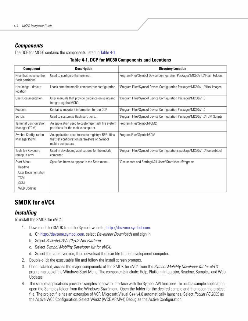
MC50 Integrator Guide4-4
ComponentsThe DCP for MC50 contains the components listed in Table 4-1.
SMDK for eVC4
InstallingTo install the SMDK for eVC4:
1. Download the SMDK from the Symbol website, http://devzone.symbol.com:a. On http://devzone.symbol.com, select Developer Downloads and sign in.b. Select PocketPC/WinCE/CE.Net Platform.c. Select Symbol Mobility Developer Kit for eVC4.d. Select the latest version, then download the .exe file to the development computer.
2. Double-click the executable file and follow the install screen prompts.3. Once installed, access the major components of the SMDK for eVC4 from the Symbol Mobility Developer Kit for eVC4
program group of the Windows Start Menu. The components include: Help, Platform Integrator, Readme, Samples, and Web Updates.
4. The sample applications provide examples of how to interface with the Symbol API functions. To build a sample application, open the Samples folder from the Windows Start menu. Open the folder for the desired sample and then open the project file. The project file has an extension of VCP. Microsoft Visual C++ v4.0 automatically launches. Select Pocket PC 2003 as the Active WCE Configuration. Select Win32 (WCE ARMV4) Debug as the Active Configuration.
Table 4-1. DCP for MC50 Components and Locations
Component Description Directory Location
Files that make up the flash partitions
Used to configure the terminal. Program Files\Symbol Device Configuration Packages\MC50\v1.0\Flash Folders
Hex image - default location
Loads onto the mobile computer for configuration. \Program Files\Symbol Device Configuration Packages\MC50\v1.0\Hex Images
User Documentation User manuals that provide guidance on using and integrating the MC50.
\Program Files\Symbol Device Configuration Packages\MC50\v1.0
Readme Contains important information for the DCP. \Program Files\Symbol Device Configuration Packages\MC50\v1.0
Scripts Used to customize flash partitions. \Program Files\Symbol Device Configuration Packages\MC50\v1.0\TCM Scripts
Terminal Configuration Manager (TCM)
An application used to customize flash file system partitions for the mobile computer.
Program Files\Symbol\TCM2
Symbol Configuration Manager (SCM)
An application used to create registry (.REG) files that set configuration parameters on Symbol mobile computers.
Program Files\Symbol\SCM
Tools (ex Keyboard remap, if any)
Used in developing applications for the mobile computer.
\Program Files\Symbol Device Configurations package\MC50\v1.0\Tools\kbtool
Start Menu:ReadmeUser DocumentationTCM SCM WEB Updates
Specifies items to appear in the Start menu. \Documents and Settings\All Users\Start Menu\Programs

Software Installation on Development PC 4-5
If both Microsoft Visual C++ v3.0 and Microsoft Visual C++ v4.0 are installed on the development computer, ensure Microsoft Visual C++ v4.0 launches.
SMDK for eVC4 Contents and LocationsThe SMDK for eVC4 contains the components listed in Table 4-2.
Installing Other Development SoftwareDeveloping applications for the mobile computer may require installing other development software such as application development environments on the development PC. Follow the installation instructions provided with this software.
Software UpdatesDownload updates to the SMDK for eVC4 from the Symbol Developer Zone web site at http://devzone.symbol.com. Check this site periodically for important updates and new software versions.
Table 4-2. SMDK for eVC4 Contents and Locations
Components Directory Location
API Help file and Readme file \Program Files\Symbol Mobility Developer Kit vx.x for eVC4\
Sample applications for quick-start development \Program Files\Symbol Mobility Developer Kit vx.x for eVC4\Samples\evc\
Header files with API prototypes and structures* \Program Files\Windows CE Tools\wce420\Pocket PC 2003\Include\armv4
Import Library files* \Program Files\Windows CE Tools\wce420\Pocket PC 2003\Lib\armv4
Start Menu ReadmeHelpPlatform IntegratorSamplesWEB Updates
\Documents and Settings\All Users\Start Menu\Programs
* The header files and lib files are time and date stamped so they can be easily identified in the armv4 directories. The "date" is the date on which the software release was assembled and the time is the version of the release. For example, a time of 1:00 signifies version 1.0.

MC50 Integrator Guide4-6

Software Installation on Mobile Computer
Introduction . . . . . . . . . . . . . . . . . . . . . . . . . . . . . . . . . . . . . . . . . . . . . . . . . . . . . . . . . . . . . . . . . . . . . . . . . . . . 5-3Downloading Files Using ActiveSync. . . . . . . . . . . . . . . . . . . . . . . . . . . . . . . . . . . . . . . . . . . . . . . . . . . . . . . . . . 5-3Downloading Files Using an MMC/SD Card . . . . . . . . . . . . . . . . . . . . . . . . . . . . . . . . . . . . . . . . . . . . . . . . . . . . 5-4Adding Programs . . . . . . . . . . . . . . . . . . . . . . . . . . . . . . . . . . . . . . . . . . . . . . . . . . . . . . . . . . . . . . . . . . . . . . . . . 5-4
Adding a Program from the Internet . . . . . . . . . . . . . . . . . . . . . . . . . . . . . . . . . . . . . . . . . . . . . . . . . . . . . . 5-5Other Downloading Methods. . . . . . . . . . . . . . . . . . . . . . . . . . . . . . . . . . . . . . . . . . . . . . . . . . . . . . . . . . . . . . . . 5-5

MC50 Integrator Guide5-2

Software Installation on Mobile Computer 5-3
IntroductionWith the appropriate accessory, software, and connection, the mobile computer can share information with the host device. This chapter provides information about installing software and files on the mobile computer.
Downloading Files Using ActiveSyncUse ActiveSync to copy files from a host computer to the mobile computer.
1. Install ActiveSync on the host computer (see Chapter 3, ActiveSync).2. Connect the mobile computer to the host computer using a USB cradle or the CAM (see Chapter 2, Accessories for
connection information).3. Set up a partnership between the host computer and the mobile computer (see Setting up a Partnership on page 3-7).4. On the host computer, select Start - Programs - ActiveSync.
Figure 5-1. ActiveSync Connected Window
5. Select Explore.
Figure 5-2. ActiveSync Explorer

MC50 Integrator Guide5-4
6. Tap the plus sign (+) next to My Pocket PC to expand the contents of this folder.
Figure 5-3. My Pocket PC Contents
7. Use Explorer to locate the host computer directory that contains the file to download. Tap that directory in the left pane to display its contents in the right pane.
8. Drag the file to one of the following My Pocket PC folders in the left pane:• Program Files folder: files stored in this folder are discarded after a cold boot.• Application folder: files stored in this folder are retained after a cold boot.
Downloading Files Using an MMC/SD CardUse an MMC or an SD card to copy files from a host computer to the mobile computer.
1. Insert the card in the appropriate drive on the host computer.2. Use Explorer to locate the host computer directory that contains the file to download. Tap that directory in the left pane to
display its contents in the right pane.3. Drag the file to the card drive in the left pane.4. Remove the card from the host computer, and insert it in the mobile computer (see Multi Media Card (MMC) / Secure Device
(SD) Card on page 2-4).5. Use File Explorer on the mobile computer to locate the file on the card drive, and copy it to a directory on the mobile
computer.
Adding ProgramsInstall the appropriate software on the host computer before installing it on the mobile computer:
1. On the mobile computer, select Start - Settings - System tab - About icon - Version tab. Note the information in Processor field.
2. Download the program to the host computer (or insert the CD or disk that contains the program into the host computer). The program may consist of a single *.xip file, *.exe file, a *.zip file, or a Setup.exe file.
3. Read any installation instructions, Read Me files, or documentation that comes with the program. Many programs provide special installation instructions.

Software Installation on Mobile Computer 5-5
4. Connect the mobile computer to the host computer.5. Double-click the executable file on the host computer.
If the file is an installer, the installation wizard begins. Follow the directions on the window. Once the software is installed on the host computer, the installer transfers the software to the mobile computer.
If the file is not an installer, an error message states that the program is valid but is designed for a different type of computer. Move this file to the mobile computer. Follow the installation instructions for the program in the Read Me file or documentation, or use ActiveSync Explore to copy the program file to the Program Files folder on the terminal as described in Downloading Files Using ActiveSync. For more information on copying files using ActiveSync, see ActiveSync Help.
6. When installation is complete, tap Start - Programs on the terminal, then tap the program icon.
Adding a Program from the Internet1. Select Start - Settings - About icon - Version tab. Note the information in Processor field.2. Download the program to the mobile computer from the Internet using Pocket Internet Explorer (see the Microsoft®
Windows Mobile 2003 for Pocket PC User Guide, p/n 72E-68197-xx for information on Pocket Internet Explorer). The program may consist of a single *.xip file, *.exe file, a *.zip file, or a Setup.exe file.
3. Read any installation instructions, Read Me files, or documentation that comes with the program. Many programs provide special installation instructions.
4. Tap the file, such as a *.xip or *.exe file, to launch the installation wizard. Follow the directions on the window.
Other Downloading MethodsFor other methods of downloading to the mobile computer, see:
• Chapter 6, Creating and Loading Hex Images to download customized flash file system partitions to the mobile computer and load hex files to the flash memory of the mobile computer.
• Chapter 7, Symbol Configuration Manager (SCM) to download registry (.REG) files that set configuration parameters on the mobile computer.
• Chapter 9, AirBEAM Smart to transfer special software packages from a host server to the mobile computer.

MC50 Integrator Guide5-6

Creating and Loading Hex Images
Introduction . . . . . . . . . . . . . . . . . . . . . . . . . . . . . . . . . . . . . . . . . . . . . . . . . . . . . . . . . . . . . . . . . . . . . . . . . . . . 6-3Starting Terminal Configuration Manager. . . . . . . . . . . . . . . . . . . . . . . . . . . . . . . . . . . . . . . . . . . . . . . . . . . . . . 6-4Defining Script Properties . . . . . . . . . . . . . . . . . . . . . . . . . . . . . . . . . . . . . . . . . . . . . . . . . . . . . . . . . . . . . . . . . . 6-7Creating the Script for the Hex Image . . . . . . . . . . . . . . . . . . . . . . . . . . . . . . . . . . . . . . . . . . . . . . . . . . . . . . . . . 6-8
Opening a New or Existing Script . . . . . . . . . . . . . . . . . . . . . . . . . . . . . . . . . . . . . . . . . . . . . . . . . . . . . . . . 6-8Updating TCM 1.X Scripts . . . . . . . . . . . . . . . . . . . . . . . . . . . . . . . . . . . . . . . . . . . . . . . . . . . . . . . . . . . . . . 6-8Copying Components to the Script . . . . . . . . . . . . . . . . . . . . . . . . . . . . . . . . . . . . . . . . . . . . . . . . . . . . . . . 6-8Saving the Script . . . . . . . . . . . . . . . . . . . . . . . . . . . . . . . . . . . . . . . . . . . . . . . . . . . . . . . . . . . . . . . . . . . . . 6-8
Building the Image . . . . . . . . . . . . . . . . . . . . . . . . . . . . . . . . . . . . . . . . . . . . . . . . . . . . . . . . . . . . . . . . . . . . . . . .6-9Downloading the Hex Image using a USB Connection . . . . . . . . . . . . . . . . . . . . . . . . . . . . . . . . . . . . . . . . . . . 6-10Downloading the Hex Image using an MMC/SD Card . . . . . . . . . . . . . . . . . . . . . . . . . . . . . . . . . . . . . . . . . . . 6-13TCM Error Messages . . . . . . . . . . . . . . . . . . . . . . . . . . . . . . . . . . . . . . . . . . . . . . . . . . . . . . . . . . . . . . . . . . . . . 6-15IPL Error Detection . . . . . . . . . . . . . . . . . . . . . . . . . . . . . . . . . . . . . . . . . . . . . . . . . . . . . . . . . . . . . . . . . . . . . . .6-16Flash Storage . . . . . . . . . . . . . . . . . . . . . . . . . . . . . . . . . . . . . . . . . . . . . . . . . . . . . . . . . . . . . . . . . . . . . . . . . . . 6-18
FFS Partitions . . . . . . . . . . . . . . . . . . . . . . . . . . . . . . . . . . . . . . . . . . . . . . . . . . . . . . . . . . . . . . . . . . . . . . .6-18Working with FFS Partitions . . . . . . . . . . . . . . . . . . . . . . . . . . . . . . . . . . . . . . . . . . . . . . . . . . . . . . . . . . . 6-18Non-FFS Partitions . . . . . . . . . . . . . . . . . . . . . . . . . . . . . . . . . . . . . . . . . . . . . . . . . . . . . . . . . . . . . . . . . . . 6-19Downloading Partitions to the Mobile Computer . . . . . . . . . . . . . . . . . . . . . . . . . . . . . . . . . . . . . . . . . . . 6-19
IPL . . . . . . . . . . . . . . . . . . . . . . . . . . . . . . . . . . . . . . . . . . . . . . . . . . . . . . . . . . . . . . . . . . . . . . . . . . . . . . . . . . . . 6-20Partition Update vs. File Update . . . . . . . . . . . . . . . . . . . . . . . . . . . . . . . . . . . . . . . . . . . . . . . . . . . . . . . . 6-20Upgrade Requirements . . . . . . . . . . . . . . . . . . . . . . . . . . . . . . . . . . . . . . . . . . . . . . . . . . . . . . . . . . . . . . . 6-20

MC50 Integrator Guide6-2

Creating and Loading Hex Images 6-3
IntroductionTerminal Configuration Manager (TCM) is an application used to customize flash file system partitions for the mobile computer. The most common use is to create an application partition hex file that contains the customer's application. TCM can also be used to load hex files to the flash memory of the mobile computer.
The program resident on the mobile computer that receives the hex file and burns it to the flash memory is called Initial Program Loader (IPL).
TCM scripts control customization of partitions. The scripts contain all the necessary information for building an image. The script is a list of copy commands specifying the files to copy from the development computer to the partition.
TCM works with a pair of directory windows, one displaying the script and the other displaying the source files resident on the development computer. Use standard windows drag-and-drop operations to add and delete files from the script window.
The Device Configuration Package (DCP) includes scripts used by Symbol Technologies to build the standard factory installed Platform and Application partitions provided on the mobile computer. The standard Platform partition contains drivers while the Application partition contains demo applications and optional components. The standard TCM scripts reside in the following folder:
C:\Program Files\Symbol Device Configuration Packages\MC50\v1.0\TCM Scripts.
Before creating a script to build a hex image, identify the files required (system files, drivers, applications, etc.) and locate the files’ source directories to make the script building process easier.
The process for building and loading a hex image using TCM includes:
• Starting TCM• Defining script properties• Creating the script for the hex image• Building the image• Downloading the hex image to the mobile computer.
The screen images used in this chapter are samples only; MC50 screens may differ slightly.

MC50 Integrator Guide6-4
Starting Terminal Configuration ManagerTo start TCM on the host computer, select Start - Programs - Symbol Device Configuration Packages - MC50v1.1 - TCM. The TCM window appears displaying two sub-windows: Script1 and File Explorer. The Script1 window contains a newly created script and the File Explorer window contains a file explorer view used for selecting files to be placed in the script.
Figure 6-1. Sample TCM Startup Window

Creating and Loading Hex Images 6-5
Table 6-1 lists the components of the TCM window.
Table 6-1. TCM Components
Icon Component Function
Script Window Displays the files to use in creating the partition(s).
File Explorer Window Used to select the files to be added to the script.
Create button Create a new script file.
Open button Open an existing script file.
Save button Save the current script file.
Large icons button View the current script items as large icons.
Small icons button View the current script items as small icons.
List button View the current script items as a list.
Details button View the current script items with more details.

MC50 Integrator Guide6-6
About button Display version information for TCM.
Properties button View/change the current script properties.
Build button Build the current script into a set of hex files.
Check button Check the script for errors (files not found).
Load button Download the hex image to the mobile computer.
Tile button Arrange the sub-windows in a tiled orientation.
Build and Load Build the current script into a set of hex images and download the hex images to the mobile computer.
Preferences button View/change global TCM options.
Table 6-1. TCM Components (Continued)
Icon Component Function

Creating and Loading Hex Images 6-7
Defining Script PropertiesBefore creating a script, define script properties, including the type of mobile computer, flash type, number of disks being created, and the memory configuration of each disk partition.
To define script properties:
1. Select the Script window to make it active.2. Click the Properties button. The Script Properties window - Partition Data tab appears.
Figure 6-2. Sample Script Properties Window - Partition Data Tab
3. In the Terminal drop-down list, select MC50 v1.0 64M.4. Use the default Flash Type.5. In the Disks drop-down list, select the number of disk partitions to create.6. Select the (memory) Size for each partition. Note that adding space to one disk partition subtracts it from another.7. In the Access drop-down list for each disk partition, select the Read/Write access option.8. Click the Options tab. The Script Properties window - Options tab appears.
Figure 6-3. Sample Script Properties Window - Options Tab
9. Set the paths for the Script File, Flash File, and Hex File Build.10. Click OK.

MC50 Integrator Guide6-8
Creating the Script for the Hex ImageOn start-up, TCM displays the TCM window with the Script1 window and File Explorer window pointing to the following directory:
\Program Files\Symbol Device Configuration Packages\MC50\v1.0\TCMScripts\
The Script1 window directory pane displays two partitions: Platform and Application. Depending on the type of flash chip, the number of partitions can change. Files can be added to each partition. TCM functionality includes:
• Opening a new or existing script file• Copying components to the script window• Saving the script file.
Opening a New or Existing ScriptA script file can be created from scratch or based on an existing script file. Click Create to create a new script or click Open to open an existing script (for example, a script provided in the DCP for MC50). Saving changes to an existing script overwrites the original script. To use an original or Symbol supplied standard script as a base and save the changes in a new script, use the Save As function to save the script using a different file name.
Updating TCM 1.X ScriptsTo upgrade script files created with older versions of TCM to TCM 2.0, click Open to open the script. The Conversion window appears.
Figure 6-4. Conversion Window - Upgrading to TCM 2.0
Select a version then click OK to save the script with that version.
Copying Components to the ScriptTo manage script contents use standard file operations such as New Folder, Delete, and Rename. To add items to the script click files and folders in the File Explorer window and drag them to the Script window. The File Explorer window supports standard Windows operations; select multiple files by clicking while holding the SHIFT or CTRL keys.
Saving the ScriptTo save modifications to a script use the Save or the Save As function. Saving changes to an existing script overwrites the original script. To use a Symbol-supplied standard script as a base and save the changes in a new script, use the Save As function.

Creating and Loading Hex Images 6-9
Building the ImageAfter creating the script, build the hex image defined by the script.
As part of the build, TCM checks the script to verify that all files referenced in the script exist. This check is important for previously created scripts to ensure that files referenced in the script are still in the designated locations.
To build scripts:
1. Click Build on the TCM toolbar. The Configure Build window appears.
Figure 6-5. Sample Configure Build Window
2. Select the items (partitions) to build using the check box(es) to the left of each partition.The Build Path defines where to store all built partitions.
3. Select (hex image) Compression to reduce the size and speed up the download.4. Click OK and follow the on-screen instructions.5. TCM performs a check and, if there are no errors, creates the partition hex files.
If the build fails, TCM does not create the hex files and displays an error message. Two of the most common reasons for a build failure are:
• Files defined in the script cannot be found. This error can occur when the files referenced by the script are no longer stored on the development computer or the folders where they are stored were renamed.
• The total amount of flash memory space required by the script exceeds the image size. To correct this, reduce the number of files in the partition or increase the size of the partition. See Defining Script Properties on page 6-7 for more information about setting the image size appropriately.

MC50 Integrator Guide6-10
Downloading the Hex Image using a USB ConnectionAfter building the hex file, download it to the mobile computer:
1. Press and hold the Power button and both Scan buttons, then press the Reset button. When the mobile computer resets into IPL, release the Power and Scan buttons.
Figure 6-6. Boot into IPL Buttons
Figure 6-7. Initial Program Loader (IPL) Select Transport Menu
2. Connect the mobile computer to the development computer using the Single or Four Slot USB cradle, or CAM.
Reset ButtonPower Button
Scan Button
Symbol Technologies Inc.IPL Version XXXXXXXX
Select Transport:
USB (Default)
SD/MMC
Return to OS OK
Timeout: 55 sec
External Power Detected

Creating and Loading Hex Images 6-11
3. Select USB (Default) for the method of download, then select OK.
Figure 6-8. Initial Program Loader (IPL) Select Partition Menu
To ensure a successful download, do not remove power from the mobile computer while in IPL mode.
4. Choose Automatic or select the partition to download, then select OK.
If the platform or application partition sizes change, first download a new partition table.
Table 6-2. IPL Menu Partitions
Partition Name Description
Windows CE Contains the operating system for the mobile computer.
Application Contains the files in the Application folder.
Platform Contains the files in the Platform folder.
IPL Contains the latest IPL version.
Partition Table Contains the partition information for all other partitions.Note: The partition table should only need changing if the sizes of the platform and application images change within TCM. If this is done, load the new partition table first, then platform and application in any order.
Automatic Select this item to download one or more files without having to manually select the destination. (The content of the downloaded files directs the file to the correct destination.) For technical reasons, Auto Select cannot be used to download Monitor, Power Micro, or Partition Table. These items must be selected.
Symbol Technologies Inc.IPL Version XXXXXXXX
Select Partition
Windows CE
Application
Platform
IPL
Partition Table
Automatic
Return to Main OK
CAUTION

MC50 Integrator Guide6-12
The following window appears:
Figure 6-9. Waiting Host Download Window
5. On the development computer, click Load on the TCM toolbar. The Load Terminal window - Serial tab appears.
Figure 6-10. Load Terminal Window - Serial Tab
Select the Image Files To Load, Comm Port, and Baud Rate from their respective drop-down lists, then click Download to begin the operation.
6. The Downloading window on mobile computer displays the Device Status and a progress bar. When complete, Device Status displays Result was Success, or in the case of an error, the cause of the error. Press Enter to return to the IPL menu to select the next partition to download.
7. To exit IPL, select the System Reset item from the IPL menu (see Figure 6-12 on page 6-13).
Symbol Technologies Inc.IPL Version XXXXXXXX
USBUpgrading
Start USB download thread!
Waiting for host download!
Waiting for Download...
Press Push to Talk to exit

Creating and Loading Hex Images 6-13
Downloading the Hex Image using an MMC/SD CardAfter building the hex file, download it to the mobile computer:
1. Press and hold the Power button and both Scan buttons, then press the Reset button. When the mobile computer resets into IPL, release the Power button and Scan buttons.
Figure 6-11. Initial Program Loader (IPL) Select Transport Menu
2. Select SD/MMC for the method of download, then select OK.
Figure 6-12. Initial Program Loader (IPL) Select Partition Menu
To ensure a successful download, do not remove power from the mobile computer while in IPL mode.
Symbol Technologies Inc.IPL Version XXXXXXXX
Select Transport
USB (Default)
SD/MMC
Return to OS OK
Timeout: 55 sec
External Power Detected
Symbol Technologies Inc.IPL Version XXXXXXXX
Select Partition
Windows CE
Application
Platform
IPL
Partition Table
Automatic
Return to Main OK
CAUTION

MC50 Integrator Guide6-14
3. Choose Automatic or select the partition to download, then select OK.
If the platform or application partition sizes change, first download a new partition table.
The following window appears:
Figure 6-13. Waiting SD Card Insert Window
4. Insert the card in the mobile computer SD/MMC card slot, then select OK on the Waiting for SD/MMC Card Insert window.5. The Downloading window on mobile computer displays the Device Status and a progress bar. When complete, Device Status
displays Result was Success, or in the case of an error, the cause of the error. Press Enter to return to the IPL menu to select the next partition to download.
6. To exit IPL, select the System Reset item from the IPL menu (see Figure 6-12 on page 6-13).
Table 6-3. IPL Menu Partitions
Partition Name Description
Windows CE Contains the operating system for the mobile computer.
Application Contains the files in the Application folder.
Platform Contains the files in the Platform folder.
IPL Contains the latest IPL version.
Partition Table Contains the partition information for all other partitions.Note: The partition table should only need changing if the sizes of the platform and application images change within TCM. If this is done, load the new partition table first, then platform and application in any order.
Automatic Select this item to download one or more files without having to manually select the destination. (The content of the downloaded files directs the file to the correct destination.) For technical reasons, Auto Select cannot be used to download Monitor, Power Micro, or Partition Table. These items must be selected.
Symbol Technologies Inc.IPL Version XXXXXXXX
SD/MMCSelect File:
Waiting SD Card insert.......
OK Back Up Down

Creating and Loading Hex Images 6-15
TCM Error MessagesTCM validates the cells in the partition table when the Execute button is clicked. Cells highlighted in red contain an error. Partition loading is disabled until all errors are corrected.
Table 6-4. TCM Error Messages
Error Description/Solution
Failed to build images: flash file system DLL not loaded!
TCM could not load the DLL required to build images for the targeting flash file system. Reinstall TCM or recover the DLL.
Failure finding directory xxx Building process failed because directory xxx was not found.
Failure creating volume Building process failed because a certain disk volume could not be created.
Failure adding system file to image Build process failed because TCM failed to add a certain system file to the disk image.
INVALID PATH The path for the image file to build is not valid.
Nothing Selected To Build In the Config Build window, no item is selected to build.
Illegal ESS ID In the Build ESSID Partition window, no ESS ID was entered or the ESS ID entered was illegal.
Disk Full TCM failed to create Hex image file at the selected path. Check available disk space.
Target Disk Full Build process failed because TCM failed to add file to the image of a disk volume. Remove some files or increase the disk size.
Hex file is READ ONLY The Hex image file to be created exists and is read-only. Delete the existing file or change its attribute.
Error opening the file xxx with write access
TCM could not open file xxx with write access. Check if file is in use.
Failure creating binary file TCM failed to open/create an intermediate binary file.
Hex File To load is missing or invalid In Load Terminal window, the file selected to load has invalid status.
Could not locate mobile computer name in TCM.ini file
While loading the Script Properties window, TCM could not find the TCM.ini section corresponding to the terminal type specified by the current opening script. Either TCM.ini or the script file is invalid.
Incorrect disk sizes in TCM.ini file The total disk size specified in the script does not match the total disk size defined in the corresponding TCM.ini section. Check if the script is corrupt or the TCM.ini has changed after the script was created.
INVALID DIRECTORY In Script Properties window, the selected System File Path is not a valid directory.
One of the disk sizes is one sector in size
In Script Properties window, one of the disks is too small (one sector in size). This may cause problem while building images, especially when cushion is enabled. Increase the disk size.
INVALID VOLUME NAME In Script Properties window, one of the volume labels is not valid.
Corrupt TCM.INI file! (Invalid value of VolumeDivisor)
The VolumeDivisor entry is missing or invalid in the TCM.ini. Reinstall TCM or recover TCM.ini.
Invalid version of TCM script file The TCM script was not created by this version of TCM.
Corrupt or missing TCM.ini file TCM could not find TCM.ini file.
FAILED CONNECTION TO COM PORT (Could not get status)
While downloading images to mobile computer, TCM failed to connect to the selected COM port. Check if the COM port is free and is properly configured.
FAILED CONNECTION TO TERMINAL (Terminal Not Connected Properly/Terminal Not Ready to Receive)
While downloading images, TCM failed to connect to the mobile computer. Check if the correct flow control protocol is selected and the mobile computer is properly connected and is in a listening state.

MC50 Integrator Guide6-16
IPL Error DetectionWhile receiving data, IPL performs many checks on the data to ensure that the data is received correctly. If IPL detects an error, it immediately aborts the download and reports the error on an error window.
Error windows vary depending on the action performed. Figure 6-14 shows a sample error window.
Figure 6-14. IPL Error Window
This error message window displays until a key press, then IPL returns to the Initial Program Loader main menu to wait for a new selection.
To find the probable cause of the error, use the error number and/or the error text on the window to locate the error in Table 6-5.
Table 6-5. IPL Errors
Error Text Error Number Probable Cause
Unknown error -1 A general error occurred. Retry the download. If the failure persists, it is most likely due to a hardware failure; the mobile computer requires servicing.
Cancelled by user -2 The user canceled the download.
Can't open the source -7 An error occurred opening the source device (either radio card or serial port). Check source device connectivity and retry.
Can't open the destination -8 An error occurred opening the destination device (either flash ROM or Power Micro). Retry the download. If the failure persists, it is most likely due to a hardware failure; the mobile computer requires servicing.
Can't read from the source device -9 The source device (either radio card or serial port) could not be read. Check source device connectivity and retry.
Can't write to the destination device
-10 Cannot write to the destination device (either flash ROM or Power Micro). Retry the download. If the failure persists, it is most likely due to a hardware failure; the mobile computer requires servicing.
Transmission checksum error -11 An error occurred during transmission from the source device (either radio card or serial port) and the checksum check failed. Check source device connectivity and retry.
Readback checksum error -12 A checksum, generated from reading back data written to the destination device, was incorrect. An error during transmission or a write error to the destination device could cause this.
There is no more heap space available
-14 There is no more heap space available for the download procedure. Restart IPL and retry the download. If the failure persists, contact service with details of what is being downloaded.
Symbol Technologies Inc.IPL Version XXXXXXXX
Downloading:Platformvia USB
Error # -2 : Messages:
Cancelled by user
Press any key to continue
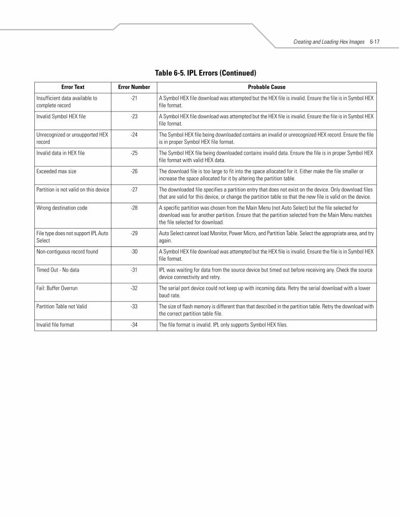
Creating and Loading Hex Images 6-17
Insufficient data available to complete record
-21 A Symbol HEX file download was attempted but the HEX file is invalid. Ensure the file is in Symbol HEX file format.
Invalid Symbol HEX file -23 A Symbol HEX file download was attempted but the HEX file is invalid. Ensure the file is in Symbol HEX file format.
Unrecognized or unsupported HEX record
-24 The Symbol HEX file being downloaded contains an invalid or unrecognized HEX record. Ensure the file is in proper Symbol HEX file format.
Invalid data in HEX file -25 The Symbol HEX file being downloaded contains invalid data. Ensure the file is in proper Symbol HEX file format with valid HEX data.
Exceeded max size -26 The download file is too large to fit into the space allocated for it. Either make the file smaller or increase the space allocated for it by altering the partition table.
Partition is not valid on this device -27 The downloaded file specifies a partition entry that does not exist on the device. Only download files that are valid for this device, or change the partition table so that the new file is valid on the device.
Wrong destination code -28 A specific partition was chosen from the Main Menu (not Auto Select) but the file selected for download was for another partition. Ensure that the partition selected from the Main Menu matches the file selected for download.
File type does not support IPL Auto Select
-29 Auto Select cannot load Monitor, Power Micro, and Partition Table. Select the appropriate area, and try again.
Non-contiguous record found -30 A Symbol HEX file download was attempted but the HEX file is invalid. Ensure the file is in Symbol HEX file format.
Timed Out - No data -31 IPL was waiting for data from the source device but timed out before receiving any. Check the source device connectivity and retry.
Fail: Buffer Overrun -32 The serial port device could not keep up with incoming data. Retry the serial download with a lower baud rate.
Partition Table not Valid -33 The size of flash memory is different than that described in the partition table. Retry the download with the correct partition table file.
Invalid file format -34 The file format is invalid. IPL only supports Symbol HEX files.
Table 6-5. IPL Errors (Continued)
Error Text Error Number Probable Cause
MC50 Integrator Guide6-18
Flash StorageIn addition to the RAM-based storage standard on Windows CE mobile computers, the mobile computer also contains a non-volatile Flash-based storage area which can store data (partitions) that a cold boot cannot corrupt. This Flash area is divided into two categories: Flash File System (FFS) Partitions and Non-FFS Partitions.
FFS PartitionsThe mobile computer includes two FFS partitions which appear to the mobile computer as a hard drive that the OS file system can write files to and read files from. Data is retained even if power is removed.
The two FFS partitions appear as two separate folders in the Windows CE file system and are as follows:
• Platform: The Platform FFS partition contains Symbol-supplied programs and Dynamic Link Libraries (DLLs). This FFS is configured to include DLLs that control system operation. Since these drivers are required for basic mobile computer operation, only experienced users should modify the content of this partition.
• Application: The Application FFS partition stores application programs needed to operate the mobile computer.
Working with FFS PartitionsBecause the FFS partitions appear as folders under the Windows CE file system, they can be written to and read like any other folder. For example, an application program can write data to a file located in the Application folder just as it would to the Windows folder. However, the file in the Application folder is in non-volatile storage and is not lost on a cold boot (e.g., when power is removed for a long period of time).
Use standard tools such as ActiveSync to copy files to and from the FFS partitions. They appear as the “Application” and “Platform” folders to the ActiveSync explorer. This is useful when installing applications on the mobile computer. Applications stored in the Application folder are retained even after cold-booting the mobile computer, just as the MC50 Demo program is retained in memory.
The Windows CE image includes two device drivers to assist developers in configuring the mobile computer following a cold boot: RegMerge and CopyFiles.
RegMerge.dllRegMerge.dll is a built-in driver that allows registry edits to be made to the Windows CE Registry. Regmerge.dll runs very early in the boot process and looks for registry files (.reg files) in certain Flash File System folders during a cold boot. It then merges the registry changes into the system registry located in RAM.
Since the registry is re-created on every cold boot from the default ROM image, the RegMerge driver is necessary to make registry modifications persistent over cold boots.
RegMerge is configured to look in the root of two specific folders for .reg files in the following order:
\Platform
\Application
Regmerge continues to look for .reg files in these folders until all folders are checked. This allows folders later in the list to override folders earlier in the list. This way, it is possible to override Registry changes made by the Platforms partitions folders. Take care when using Regmerge to make Registry changes. The DCP for MC50 contains examples of .reg files.
Regmerge only merges the .reg files on cold boots. A warm boot skips the merge process.

Creating and Loading Hex Images 6-19
Typically, do not modify registry values for drivers loaded before RegMerge. However, these values can require modification during software development. Since these early loading drivers read these keys before RegMerge gets a chance to change them, the mobile computer must be cold booted. A warm boot does not re-initialize the registry and the early loading driver reads the new registry values.
Do not use Regmerge to modify built-in driver registry values, or merge the same Registry value to two files in the same folder, as the results are undefined.
CopyFilesWindows CE expects certain files to be in the Windows folder, residing in volatile storage. Windows CE maintains the System Registry in volatile storage. CopyFiles copies files from one folder to another on a cold boot. Files can be copied from a non-volatile partition (Application or Platform) to the Windows or other volatile partition during a cold boot. During a cold boot CopyFiles looks for files with a .CPY extension in the root of the Platform and Application FFS partitions (Platform first, then Application). These text files contain the source and destination for the desired files to copy separated by “>”. The DCP for MC50’s demo application partition includes the following example from the file application.cpy. Alternatively, obtain this from the Symbol web site athttp://devzone.symbol.com/.
Files are copied to the Windows folder from the Flash File System using copy files (*.cpy) in the following order:
\Platform
\Application
Example:
\Application\ScanSamp2.exe>\Windows\ScanSamp2.exe
This line directs CopyFiles to copy the ScanSamp2.exe application from the \Application folder to the \Windows folder.
Non-FFS PartitionsNon-FFS Partitions include additional software and data pre-loaded on the mobile computer that can be upgraded. Unlike FFS Partitions, these partitions are not visible when the operating system is running. They also contain system information. Non-FFS partitions include the following:
• Windows CE: The complete Windows CE operating system is stored on Flash devices. If necessary, download the entire OS image to the mobile computer using Symbol-provided files. The TCM installation package includes the current OS partition on the mobile computer. Obtain any upgrades from Symbol. This partition is mandatory for the mobile computer.
• IPL: This program interfaces with the host computer and allows downloading via cradle or cable any or all of the partitions listed above, as well as updated versions of IPL. Use caution downloading updated IPL versions; incorrect IPL downloading causes permanent damage to the mobile computer. IPL is mandatory for the mobile computer.
• Partition Table: Identifies where each partition is loaded in the mobile computer.
Downloading Partitions to the Mobile ComputerTCM is used to specify a hex destination file for each partition and download each file to the mobile computer. The mobile computer includes a program loading utility, Initial Program Loader (IPL), stored in write-protected flash.

MC50 Integrator Guide6-20
IPLIPL allows upgrading the mobile computer with software updates and/or feature enhancements.
Partition Update vs. File UpdateThere are two types of update supported by the mobile computer: partitions and files. The file system used by the mobile computer is the same as the file system used on a desktop computer. A file is a unit of data accessed using a file name and a location in the file system. Replacing a file erases only the contents of the previous file. The operating system must be running to update a file, so the IPL cannot perform individual file updates as it is a stand-alone program that does not require the operating system to be running.
A typical partition is a group of files, combined into a single "partition" that represents a specific area of storage. Examples of partitions are the flash file systems such as Platform or Application. (Using the desktop computer comparison, these partitions are roughly equivalent to a C: or D: hard disk drive.) In addition to the "hard disk" partitions, some partitions are used for single items such as the operating system or monitor. (Again using a desktop computer comparison, these partitions are similar to the BIOS or special hidden system files.) Updating a partition erases all data in its storage region, i.e., it is not a merge but rather a replacement operation. Typically, the operating system is not running when updating partitions, so IPL can perform partition updates.
Partition images for selected partitions can be created by TCM. All partition images suitable for use by IPL are in hex file format for transfer by TCM from the development computer to the mobile computer.
Upgrade RequirementsUpgrade requirements:
• The hex files to download (on development computer)• A connection from the host computer and the mobile computer (either serial or wireless)• TCM (on development computer) to download the files.
After meeting these requirements, upgrade the mobile computer by invoking IPL and navigating the menus. See Downloading the Hex Image using an MMC/SD Card on page 6-13 for procedures on downloading a hex file to the mobile computer.
Symbol Configuration Manager (SCM)
Introduction . . . . . . . . . . . . . . . . . . . . . . . . . . . . . . . . . . . . . . . . . . . . . . . . . . . . . . . . . . . . . . . . . . . . . . . . . . . . 7-3File Types . . . . . . . . . . . . . . . . . . . . . . . . . . . . . . . . . . . . . . . . . . . . . . . . . . . . . . . . . . . . . . . . . . . . . . . . . . . . . . . 7-3User Interface. . . . . . . . . . . . . . . . . . . . . . . . . . . . . . . . . . . . . . . . . . . . . . . . . . . . . . . . . . . . . . . . . . . . . . . . . . . . 7-3
Menu Functions . . . . . . . . . . . . . . . . . . . . . . . . . . . . . . . . . . . . . . . . . . . . . . . . . . . . . . . . . . . . . . . . . . . . . . 7-4Parameter State Indicators . . . . . . . . . . . . . . . . . . . . . . . . . . . . . . . . . . . . . . . . . . . . . . . . . . . . . . . . . . . . .7-4Window Status Bar . . . . . . . . . . . . . . . . . . . . . . . . . . . . . . . . . . . . . . . . . . . . . . . . . . . . . . . . . . . . . . . . . . . 7-5
Registry File Deployment . . . . . . . . . . . . . . . . . . . . . . . . . . . . . . . . . . . . . . . . . . . . . . . . . . . . . . . . . . . . . . . . . . . 7-5

MC50 Integrator Guide7-2

Symbol Configuration Manager (SCM) 7-3
IntroductionSymbol Configuration Manager (SCM.exe) is a utility that runs on the development computer and is used to create a registry (.REG) file. This file, when deployed to a mobile computer, sets configuration parameters for that device. The configurable options for a mobile computer are defined in an XML file that is installed with the Device Configuration Package (DCP) for that mobile computer. SCM.exe, also installed with the DCP, is a shared executable; only the latest version is installed.
SCM provides an alternative to using Notepad to create .REG files, eliminating the potential user errors that occur when manually editing .REG files.
File TypesSCM uses three types of files:
• Symbol Configuration Template (.SCT) files are XML files delivered with DCPs that define the configurable parameters for a device.
• Symbol Configuration Document (.SCD) files are XML files that SCM creates to hold the values of any modified parameters.• Registry (.REG) file is a standard Windows format registry file that SCM creates. This file is downloaded to the mobile
computer and merged upon a cold boot.The .REG file contains the complete set of registry values for a particular device, not just the modified values.
User InterfaceSCM's user interface consists of a tree control on the left side of the window which displays all the configuration categories, and a data grid table on the right which displays all the configurable controls for the selected category. Figure 7-1 shows the main window for the MC50w.sct file.
Figure 7-1. Main SCM Window

MC50 Integrator Guide7-4
Menu FunctionsUse the main menu to access the program functionality described in Table 7-1.
Parameter State IndicatorsThe first column of the data table displays parameter state indicators. The state indicators display one of the states in Table 7-2 for a particular parameter:
Table 7-1. SCM Menu Functions
Menu Item Description
File Menu
Open Config File Open a saved configuration file (.SCD).
Save Config Changes Save changes to the currently loaded configuration file.
Restore All Defaults Restore all parameter values to the default state as defined by the installed DCP. The default values are stored in a Symbol Configuration template file (i.e., MC50w.sct).
Create .REG File Export the parameter values to a registry (.REG) file.
Exit Exit Symbol Configuration Manager.
Device Menu
MC50w Change the current device type to MC50w. If DCPs for other device types are installed on the development computer, entries for these devices also appear in the Device menu.
Help Menu
About Display the About dialog which shows the application version.
Table 7-2. Parameter Status Indicators
Icon Indicator Description
Modified This parameter was changed from its initial factory setting.
Invalid This parameter is not valid for the selected device type. This can occur when a configuration file for one type of device is loaded and the device type is changed using the Device menu. Values marked "invalid" are not included in an exported .REG file.

Symbol Configuration Manager (SCM) 7-5
Window Status BarThe SCM status bar found on the bottom right corner of the window contains the items in Table 7-3 from left to right:
Figure 7-2. Sample Status Bar
The sample status bar in Figure 7-2 shows that the current configuration file contains 1 Invalid Parameter and 2 Modified Parameters.
Registry File DeploymentThe registry file created by the SCM export function must be properly deployed to the mobile computer. The order in which registry files appear in the folder structure of the mobile computer is important. The function that processes .REG files is called "RegMerge". RegMerge first looks for registry files in the \Platform folder and merges their contents into the registry. It then looks in \Application\SCM and merges any found .REG files, and finally it looks in the \Application folder.
To understand the purpose of this order, consider the different types of registry files used on the mobile computer. Registry files appear on the mobile computer from various sources:
• Factory Settings - Some .REG files are shipped in the \Platform folder from the factory. Registry settings built into the OS image plus those found in \Platform define the default factory settings for the mobile computer. Do not modify or remove these registry files.
• SCM Settings - The registry file generated by SCM must be placed in the mobile computer’s \Application\SCM folder. This file represents user settings that override the factory defaults. An administrator uses SCM to create settings for groups of mobile computers.
• CtlPanel Settings - Registry files generated using the CtlPanel’s Persist feature are automatically placed in the \Application folder. These files represent user setting overrides for the single device where the changes were made.
Following this registry file processing order, RegMerge processes Factory settings first, then SCM settings, then finally CtlPanel settings.
Exercise care when using the CtlPanel in combination with SCM to set options, as CtlPanel settings can overwrite SCM settings. For best results, if using the SCM method, do not use the CtlPanel.
The current version of SCM does not support Scanner Settings, so use the CtlPanel method in this case.
Table 7-3. Window Status Bar Items
Status Bar Item Description
Invalid Count Number of parameters not valid for the selected device.
Modified Count Number of parameters modified from the factory defaults.
Device Type Device type - version.

MC50 Integrator Guide7-6

WLAN Configuration
Introduction . . . . . . . . . . . . . . . . . . . . . . . . . . . . . . . . . . . . . . . . . . . . . . . . . . . . . . . . . . . . . . . . . . . . . . . . . . . . 8-3Mobile Companion . . . . . . . . . . . . . . . . . . . . . . . . . . . . . . . . . . . . . . . . . . . . . . . . . . . . . . . . . . . . . . . . . . . . . . . .8-4
Finding WLANs. . . . . . . . . . . . . . . . . . . . . . . . . . . . . . . . . . . . . . . . . . . . . . . . . . . . . . . . . . . . . . . . . . . . . . . 8-4Status . . . . . . . . . . . . . . . . . . . . . . . . . . . . . . . . . . . . . . . . . . . . . . . . . . . . . . . . . . . . . . . . . . . . . . . . . . . . . 8-15Setting Options. . . . . . . . . . . . . . . . . . . . . . . . . . . . . . . . . . . . . . . . . . . . . . . . . . . . . . . . . . . . . . . . . . . . . . 8-19Changing Profiles . . . . . . . . . . . . . . . . . . . . . . . . . . . . . . . . . . . . . . . . . . . . . . . . . . . . . . . . . . . . . . . . . . . . 8-21
Using LEAP for Wireless Network Security . . . . . . . . . . . . . . . . . . . . . . . . . . . . . . . . . . . . . . . . . . . . . . . . . . . . 8-22Configuring Advanced Password Options . . . . . . . . . . . . . . . . . . . . . . . . . . . . . . . . . . . . . . . . . . . . . . . . . 8-22
Enterprise Level Wi-Fi Protected Access . . . . . . . . . . . . . . . . . . . . . . . . . . . . . . . . . . . . . . . . . . . . . . . . . . . . . . 8-24AEGIS Security Client. . . . . . . . . . . . . . . . . . . . . . . . . . . . . . . . . . . . . . . . . . . . . . . . . . . . . . . . . . . . . . . . . 8-24
Configuring the DS (11 Mb) Radio Using a Registry File . . . . . . . . . . . . . . . . . . . . . . . . . . . . . . . . . . . . . . . . . . 8-24Connecting to the Internet on a Wireless Network. . . . . . . . . . . . . . . . . . . . . . . . . . . . . . . . . . . . . . . . . . . . . . 8-25

MC50 Integrator Guide8-2

WLAN Configuration 8-3
IntroductionWireless LANs allow mobile computers to communicate wirelessly and to send captured data “real time” to a host device. Before using a mobile computer on a WLAN, set up the facility with the equipment required to run the wireless LAN and configure the mobile computer. Refer to the documentation that came with the Access Points (APs) for instructions on setting up the required hardware.
The mobile computer Network Adapter settings configure and monitor the wireless connection. The Mobile Companion icon appears in the task tray and indicates mobile computer signal strength as follows:
Icon Status
Excellent signal strength
Very good signal strength
Good signal strength
Fair signal strength
Poor signal strength
Out-of-network range (not associated)

MC50 Integrator Guide8-4
Mobile CompanionUse the Mobile Companion utility to configure the mobile computer’s wireless network settings. The Mobile Companion utility appears as an icon on the task tray. The status icon changes in real-time to reflect the signal strength and availability of the adapter and the wireless network. Tap the icon on the task tray to open the Mobile Companion menu.
Figure 8-1. Mobile Companion Menu
When the menu opens, select Status, WLAN Profiles, Find WLANs, or Options from the menu.
Finding WLANsA completed profile is a set of mobile computer configuration settings used in different locations to connect to a network. Create different profiles to have pre-defined mobile computer operating parameters available for use in various network environments.
Table 8-1. Mobile Companion Menu Descriptions
Menu Item Description
Status Displays the current status and information for the wireless connection. (See Status on page 8-15 for more information.)Signal tab - displays radio signal transmission strength from the adapter (using its current profile) to the associated AP.Info tab - displays mobile computer’s software, driver, firmware, and hardware versions, as well as country information for the current WLAN profile.IP Status tab - displays network address information.Ping tab - displays signal strength data and data rate, and conducts data transmission tests between the mobile computer and associated AP or client.APs tab - displays APs with the same ESSID within the current WLAN profile.Peers tab - displays the BSSIDs, power modes, transmit rates, and data rates of other networked clients within the Ad Hoc (peer-to-peer) network. When in Ad Hoc operating mode, the Peers tab appears instead of the APs tab.
WLAN Profiles Displays the current profiles and allows adding, editing, and deleting profiles. (See Changing Profiles on page 8-21 for more information.)
Find WLANs Displays a list of wireless networks (APs and networked peers) available to the mobile computer for association. The networks are listed by ESSID. To the right of each network is a signal strength icon. Networks with a signal strength of Good (three green bars out of five) or better should be considered for connection. Tap a network and tap Connect to interoperate with the AP representing that network. Once connected, the Mode, Authentication, Encryption, IP Config, and Power tabs display the ESSID, security settings, network address information, and power consumption level set for that network. (See Finding WLANs on page 8-4 for more information.)
Options Displays settings for system sounds, AP and mobile computer association capabilities, profile roaming options, and the password protecting the Mobile Companion utility. (See Setting Options on page 8-19 for more information.)
Mobile Companion icon
Mobile Companion menu
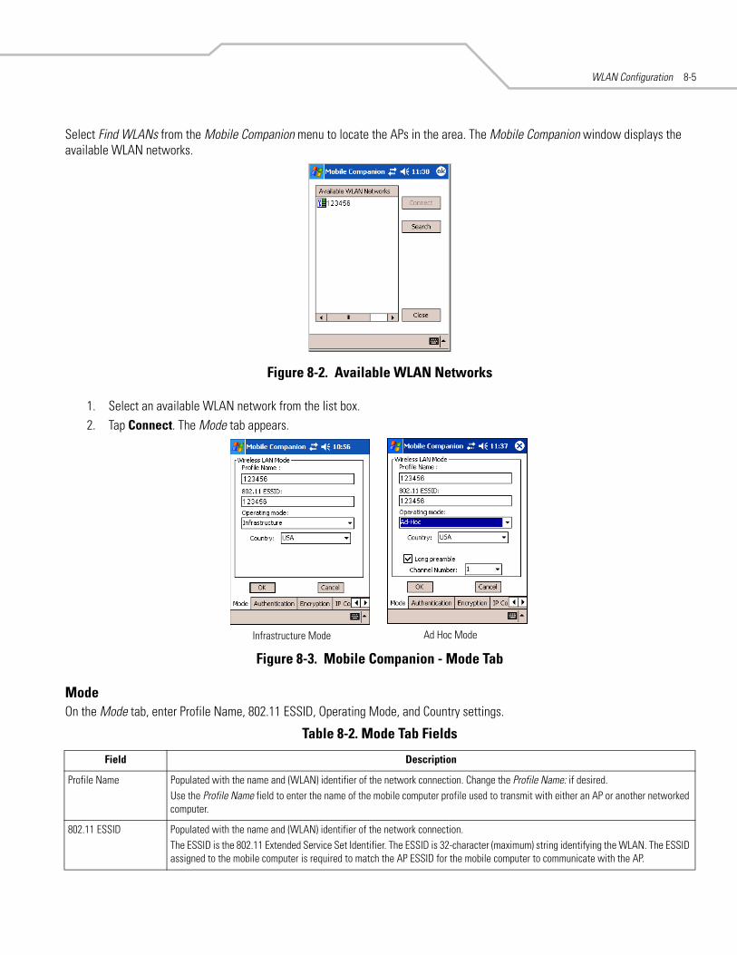
WLAN Configuration 8-5
Select Find WLANs from the Mobile Companion menu to locate the APs in the area. The Mobile Companion window displays the available WLAN networks.
Figure 8-2. Available WLAN Networks
1. Select an available WLAN network from the list box.2. Tap Connect. The Mode tab appears.
Figure 8-3. Mobile Companion - Mode Tab
ModeOn the Mode tab, enter Profile Name, 802.11 ESSID, Operating Mode, and Country settings.
Table 8-2. Mode Tab Fields
Field Description
Profile Name Populated with the name and (WLAN) identifier of the network connection. Change the Profile Name: if desired.Use the Profile Name field to enter the name of the mobile computer profile used to transmit with either an AP or another networked computer.
802.11 ESSID Populated with the name and (WLAN) identifier of the network connection.The ESSID is the 802.11 Extended Service Set Identifier. The ESSID is 32-character (maximum) string identifying the WLAN. The ESSID assigned to the mobile computer is required to match the AP ESSID for the mobile computer to communicate with the AP.
Infrastructure Mode Ad Hoc Mode

MC50 Integrator Guide8-6
AuthenticationSelect the Authentication tab to configure server-based authentication. Select one of the following Authentication options from the Authentication drop-down list.
• None - Default setting when authentication is not required on the network. The client adapter does not use any authentication scheme when Open System is selected on the Encryption tab.
• Kerberos (see Table 8-3)• LEAP (see Table 8-4)• EAP-TLS (see Table 8-5)• PEAP (see Table 8-5).
.
Figure 8-4. Mobile Companion - Authentication Tab (Kerberos)
Operating Mode Select the operating mode from the Operating Mode: drop-down list.Infrastructure: Select Infrastructure to enable the mobile computer to transmit and receive data with an AP. Infrastructure is the mobile computer default mode when Mobile Companion initially appears.Ad Hoc: Select Ad Hoc to enable the mobile computer to form its own local network where mobile computers communicate peer-to-peer without APs using a shared ESSID. Select the Long preamble check box if the mobile computer and its profile use a long preamble when transmitting data. A long preamble is approximately 8 bytes of the packet header attached to the packet prior to transmission. Devices in Ad Hoc mode must use the same preamble length to interoperate. The mobile computer initiating the Ad Hoc network sets the channel (using the Channel drop-down list) used by each peer in the Ad Hoc network.
Note: For mobile computers with a Bluetooth radio, the Bluetooth radio must be turned off when using 802.11b Ad Hoc mode, otherwise the Ad Hoc connection fails.
Country Select the country of operation for the mobile computer from the Country: drop-down list. This ensures the mobile computer is using country code information compatible with the country code data used by the associated AP.
Table 8-2. Mode Tab Fields (Continued)
Field Description
Kerberos Authentication Credential Caching Settings(Kerberos Options)
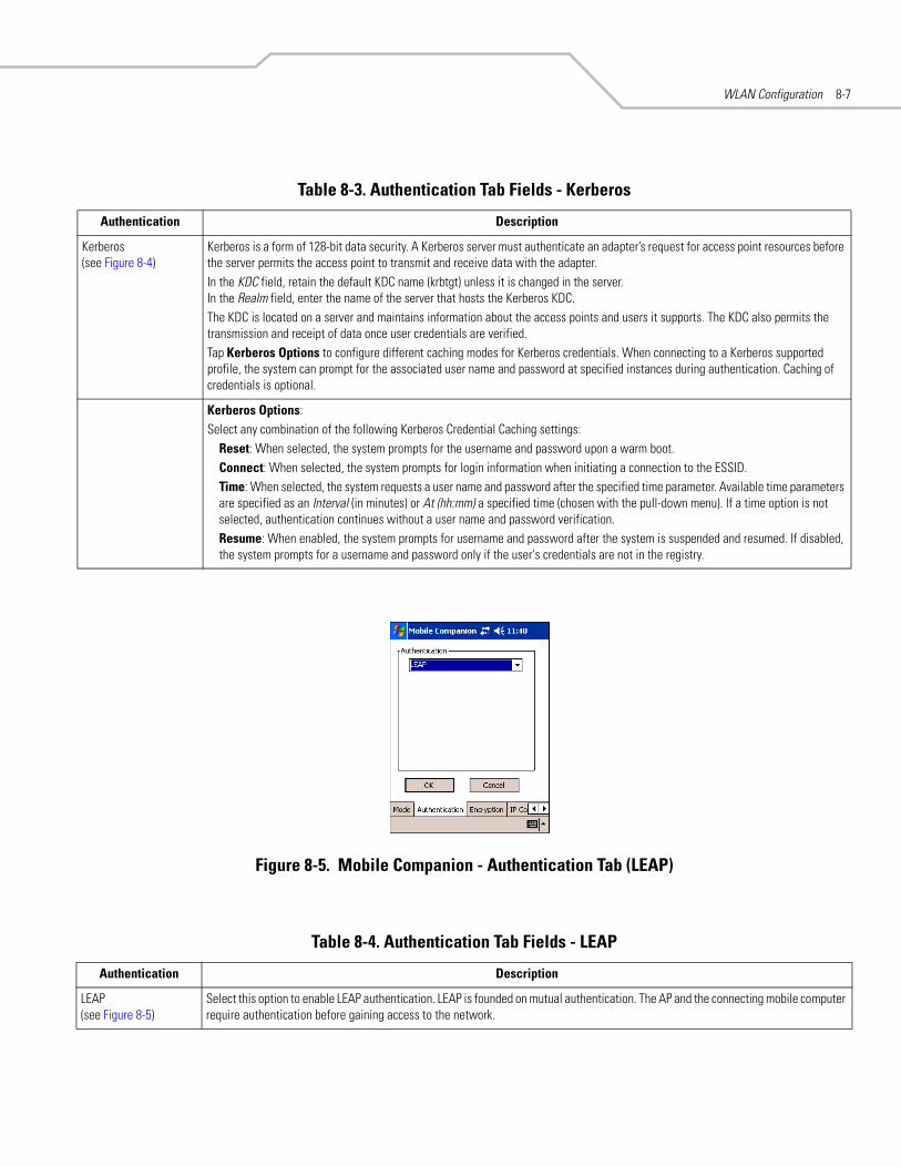
WLAN Configuration 8-7
Figure 8-5. Mobile Companion - Authentication Tab (LEAP)
Table 8-3. Authentication Tab Fields - Kerberos
Authentication Description
Kerberos(see Figure 8-4)
Kerberos is a form of 128-bit data security. A Kerberos server must authenticate an adapter’s request for access point resources before the server permits the access point to transmit and receive data with the adapter. In the KDC field, retain the default KDC name (krbtgt) unless it is changed in the server. In the Realm field, enter the name of the server that hosts the Kerberos KDC. The KDC is located on a server and maintains information about the access points and users it supports. The KDC also permits the transmission and receipt of data once user credentials are verified.Tap Kerberos Options to configure different caching modes for Kerberos credentials. When connecting to a Kerberos supported profile, the system can prompt for the associated user name and password at specified instances during authentication. Caching of credentials is optional.
Kerberos Options:Select any combination of the following Kerberos Credential Caching settings:
Reset: When selected, the system prompts for the username and password upon a warm boot.Connect: When selected, the system prompts for login information when initiating a connection to the ESSID.Time: When selected, the system requests a user name and password after the specified time parameter. Available time parameters are specified as an Interval (in minutes) or At (hh:mm) a specified time (chosen with the pull-down menu). If a time option is not selected, authentication continues without a user name and password verification.Resume: When enabled, the system prompts for username and password after the system is suspended and resumed. If disabled, the system prompts for a username and password only if the user's credentials are not in the registry.
Table 8-4. Authentication Tab Fields - LEAP
Authentication Description
LEAP(see Figure 8-5)
Select this option to enable LEAP authentication. LEAP is founded on mutual authentication. The AP and the connecting mobile computer require authentication before gaining access to the network.

MC50 Integrator Guide8-8
Figure 8-6. Mobile Companion - Authentication Tab (EAP-TLS)
Figure 8-7. Mobile Companion - Authentication Tab (PEAP)
When the mobile computer is associated to an EAP or PEAP WLAN, the window shown in Figure 8-8 may be available for radio configurations. Use only the Mobile Companion Utility, located on the tasktray of the Today screen, to configure the radio.
Table 8-5. Authentication Tab Fields - EAP/TLS and PEAP
Authentication Description
EAP/TLS(see Figure 8-6)
EAP/TLS is an authentication scheme through IEEE 802.1x, ensuring only valid users can connect to the network. It also restricts unauthorized users from accessing transmitted information. EAP/TLS achieves this through secure authentication certificates.
PEAP(see Figure 8-7)
Select this option to enable PEAP authentication. This method uses a digital certificate to verify and authenticate a user's identity.

WLAN Configuration 8-9
Figure 8-8. Microsoft Wireless Configuration Windows
Installing and Viewing Certificates
To install a user certificate (EAP-TLS only) and a server certificate for EAP-TLS and PEAP authentication:
1. On the EAP-TLS or PEAP Authentication window, tap Install/View Certificates.
Figure 8-9. Manage Certificates
2. Tap User (client) to request a User Certificate (EAP-TLS only).
Figure 8-10. EAP-TLS Install User Certificate
3. Enter the User:, Password:, and Server: information in their respective text boxes.4. Tap Retrieve. A Progress dialog appears to indicate the status of the certificate retrieval.5. Tap ok to exit.
Tap to hide window

MC50 Integrator Guide8-10
6. On the Manage Certificates window, tap Root (server) to request the installation of a Server Certificate (EAP-TLS and PEAP).
Figure 8-11. EAP-TLS/PEAP Install Root Certificate
The Server Certificate must be downloaded to the mobile computer prior to installation.
7. Tap Browse to locate the Server Certificate on the mobile computer.
Figure 8-12. EAP-TLS/PEAP Browse Server Certificate
8. Select All Files (*.*) from the Type: drop-down list.9. In the list of certificates, tap the certificate to install. 10. On the Install Root Certificate window (Figure 8-11), tap Install Certificate.11. Tap ok to exit.

WLAN Configuration 8-11
12. To retrieve information about an installed certificate, tap and hold a certificate in the list and select Details from the menu.
Figure 8-13. Certificates Details
13. To display expanded details about a particular field, tap a field in the list.
Figure 8-14. Expanded Details
14. Tap ok to exit.

MC50 Integrator Guide8-12
EncryptionThe absence of a physical connection makes wireless links vulnerable to information theft. Encryption is an efficient method of preventing data theft and improving data security.
Select the Encryption tab to set the adapter profile security level by configuring the encryption scheme and corresponding keys.
Select an option (Open System, WEP, or TKIP (WPA)) from the Encryption drop-down list. See Table 8-6 for Encryption option descriptions.
Figure 8-15. Mobile Companion - Encryption Tab
The AP and the mobile computer must use the same encryption algorithm to associate and transmit data. If an AP is set to Open System and an adapter is set to 40-bit or 128-bit, no association occurs. Similarly, if an adapter is set to Open System and an AP is set to 40-bit or 128-bit, no association occurs.
If an AP is set to 40-bit and an adapter is set to 128-bit, the adapter can associate to the AP, but no data transmission and reception can occur.
Table 8-6. Encryption Tab Fields
Encryption Description
Open System Use the Open System option when no data packet encryption is needed over the network. Selecting this option provides no security for data transmitted over the network. The window displays only the ok and Cancel buttons.
WEP Select WEP for the adapter to use the WEP keys for encryption. The window displays several radio buttons and edit buttons to configure the WEP keys. Select 40-bit or 128-bit key lengths (128-bit is the default). WEP keys are manually entered in the edit boxes. Only the required number of edit boxes for a key length is displayed (10 Hex digit value for 40-bit keys, 26 Hex digit values for 128-bit keys). Use the Key radio buttons to configure the four WEP keys. The adapter uses the selected key. Tap ResetKeys to set the encryption key to the default values.Note: The default Hex digit keys are visible any time they are used. As a security precaution after setting the key values for the network, asterisks * replace the digits in the Encryption key fields. If the associated access point is using an optional Passkey, the "active" adapter WLAN profile is required to use one as well. The Passkey is a plain text representation of the WEP keys displayed in the Encryption property window. The Passkey provides an easy way to enter WEP key data without having to remember the entire 40-bit (10 character) or 128-bit (26 character) Hex digit string. Tap Passkey to display the Passkey window. Enter an easy-to-remember 4 to 32 character string to use as the WEP algorithm. Tap ok. The access point transforms the Passkey string into a set of four WEP keys using MD5 algorithms and displays them in the WEP fields. These are the new WEP keys for the adapter profile. Once displayed in the WEP key fields, the adapter profile behaves as if the keys were entered manually.
TKIP (WPA) Select this option for the client adapter to use Wireless Protected Access (WPA) via TKIP. Manually enter the pre-shared keys in the edit boxes. Tap ClearKey to clear all previous keys and enter new key values. Tap Passkey to display the Passkey window. Enter an easy-to-remember 8 to 63 character string.
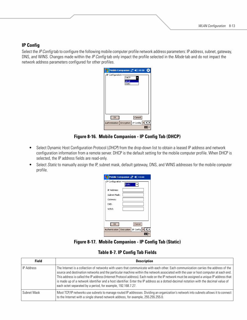
WLAN Configuration 8-13
IP ConfigSelect the IP Config tab to configure the following mobile computer profile network address parameters: IP address, subnet, gateway, DNS, and WINS. Changes made within the IP Config tab only impact the profile selected in the Mode tab and do not impact the network address parameters configured for other profiles.
Figure 8-16. Mobile Companion - IP Config Tab (DHCP)
• Select Dynamic Host Configuration Protocol (DHCP) from the drop-down list to obtain a leased IP address and network configuration information from a remote server. DHCP is the default setting for the mobile computer profile. When DHCP is selected, the IP address fields are read-only.
• Select Static to manually assign the IP, subnet mask, default gateway, DNS, and WINS addresses for the mobile computer profile.
Figure 8-17. Mobile Companion - IP Config Tab (Static)
Table 8-7. IP Config Tab Fields
Field Description
IP Address The Internet is a collection of networks with users that communicate with each other. Each communication carries the address of the source and destination networks and the particular machine within the network associated with the user or host computer at each end. This address is called the IP address (Internet Protocol address). Each node on the IP network must be assigned a unique IP address that is made up of a network identifier and a host identifier. Enter the IP address as a dotted-decimal notation with the decimal value of each octet separated by a period, for example, 192.168.7.27.
Subnet Mask Most TCP/IP networks use subnets to manage routed IP addresses. Dividing an organization's network into subnets allows it to connect to the Internet with a single shared network address, for example, 255.255.255.0.

MC50 Integrator Guide8-14
Power1. Select the Power tab to set the Radio Transmission Power level and the Power Saving Modes for the mobile computer
profile.
Figure 8-18. Mobile Companion - Power Tab
Adjusting the Radio Transmission Power level expands or confines the transmission area with respect to other wireless devices that could be operating nearby. Reducing coverage in high traffic areas improves transmission quality by reducing the number of noises in that coverage area.
Gateway The default gateway is a device used to forward IP packets to and from a remote destination.
DNS The Domain Name System (DNS) is a distributed Internet directory service. DNS is usually used to translate domain names and IP addresses. It is also used to control Internet email delivery. Most Internet service requires DNS to operate properly. If DNS is not configured, Web sites cannot be located and/or email delivery fails.
WINS WINS is a Microsoft® Net BIOS name server. WINS eliminates the broadcasts needed to resolve computer names to IP addresses by providing a cache or database of translations.
Table 8-8. Power Tab Fields
Field Description
Radio Transmission Power
In Infrastructure mode There are two transmission power options:Select Automatic to use the AP power level. Automatic is the default mode for mobile computers operating in Infrastructure mode.Select Power Plus to set the mobile computer transmission power one level higher than the level set for the AP.
In Ad Hoc mode There are five transmission power options:Select Maximum power to set the mobile computer to the highest transmission power level. Select Maximum power when operating in highly reflective environments and areas where other devices could be operating nearby, or when attempting to communicate with devices at the outer edge of a coverage area.Select 50%, 25%, or 10% to set the transmit power level to that percentage of the maximum power level.Select Minimum power to set the mobile computer to the lowest transmission power level. Use the minimum power level when communicating with other devices in very close proximity, or in instances where little or no radio interference from other devices is anticipated.
Table 8-7. IP Config Tab Fields (Continued)
Field Description
Infrastructure Mode Ad Hoc Mode

WLAN Configuration 8-15
2. Tap ok to implement power consumption changes for the mobile computer profile.
StatusTo view the status of the wireless network connection, select Status from the Mobile Companion menu.
1. Select the Signal tab to display a real-time graph of the signal quality of the mobile computer to the associated AP (Infrastructure Mode only). This tab displays the number of times the mobile computer has roamed to and from APs, the current data rate, and the network status. Signal quality indicates how clearly the adapter can hear the associated AP.
Figure 8-19. Mobile Companion - Signal Tab
The Signal tab is view-only and is not available in Ad Hoc mode.
Automatic Power Saving Mode
Switches to Best Network Performance when an AC power supply is detected. If using a battery, it chooses an appropriate setting between Best Network Performance and Acceptable Network Performance based on a real-time analysis of network usage. The Automatic Power Saving Mode is the default setting and extends the operating time before the battery is recharged.
Manual Power Saving Mode Selects a performance level suited to intended operation. There are six settings ranging from the Best Network Performance (using the most battery power) to Acceptable Network Performance (using the least battery power). A network performance description is displayed for each power range.
Table 8-9. Signal Fields
Field Description
Missed Beacons Displays the amount of beacons (uniform system packets broadcast by the AP to keep the network synchronized) missed by the mobile computer. The fewer the missed beacons the better the signal. As long as the LED to the right of the graph is green the AP association is not jeopardized by an excess of missed AP beacons. If the LED is red, an association with a different AP could be warranted to reduce the amount of missed beacons and improve the signal.
Txmit Retries (Transmit Retries)
Displays the number of data packets retransmitted by the mobile computer. The fewer transmit retries the stronger the signal. As long as the LED to the right of the graph is green the AP association is not jeopardized. If the LED is red, an association with a different AP could be warranted to reduce the amount of transmit retries and improve the signal.
Table 8-8. Power Tab Fields (Continued)
Field Description

MC50 Integrator Guide8-16
2. Select the Info tab to view the mobile computer’s current software and driver revision data as well as the operating parameters of the current profile.
Figure 8-20. Mobile Companion - Info Tab
The Version and Current Status information on this window can vary.
Signal Displays the Relative Signal Strength Indicator (RSSI) of the signal transmitted between the AP and mobile computer. As long as the LED to the right of the graph is green the AP association is not jeopardized. If the LED is red, an association with a different AP could be warranted to improve the signal.
Table 8-10. Info Fields
Field Description
Version Information Displays Mobile Companion software, driver, firmware, and hardware versions as well as country information. This data is consistent for the mobile computer regardless of the current profile.
Current Status Displays the mobile computer’s current Profile Name, ESSID, and Encryption mode. Mobile computer performance is displayed using a verbal indicator of signal strength. Mobile computer operating information differs depending on the current profile.
Table 8-9. Signal Fields (Continued)
Field Description

WLAN Configuration 8-17
3. Select the IP Status tab to view the mobile computer’s network address information. Unlike the IP Config tab in Finding WLANs, the IP Status tab is view only with no user-configurable data fields.
Figure 8-21. Mobile Companion - IP Status Tab
4. Tap Renew to refresh the information displayed (through a DHCP request) within the IP Status tab.
Table 8-11. IP Status Fields
Field Description
IP Type If DHCP was selected from the IP Config tab, leased IP address and network address data displays for the mobile computer. If Static was selected, the values displayed were input manually in the IP Config tab on page 8-13.
IP Address The Internet is a collection of networks with users that communicate with each other. Each communication carries the address of the source and destination networks and the particular machine within the network associated with the user or host computer at each end. This address is called the IP address. Each node on the IP network must have a unique IP address made up of a network identifier and a host identifier. Enter the IP address as a dotted-decimal notation with the decimal value of each octet separated by a period, for example, 192.168.7.27.
Subnet Mask Most TCP/IP networks use subnets to manage routed IP addresses. Dividing an organization's network into subnets allows it to connect to the Internet with a single shared network address, for example, 255.255.255.0.
Gateway The gateway is a device that forwards IP packets to and from a remote destination.
DNS The Domain Name System (DNS) is a distributed Internet directory service. DNS is usually used to translate domain names and IP addresses. It also controls Internet e-mail delivery. Most Internet service requires DNS to operate properly. If DNS is not configured, Web sites cannot be located or e-mail delivery fails.
WINS WINS is a Microsoft Net BIOS name server. WINS eliminates the broadcasts needed to resolve computer names to IP addresses by providing a cache or database of translations.
MAC Address An IEEE 48-bit address assigned to the mobile computer at the factory that uniquely identifies the adapter at the physical layer.
Host Name Displays the name of the mobile computer.

MC50 Integrator Guide8-18
5. Select the Ping tab to send and receive ICMP ping packets across the network to the specified IP address.
Figure 8-22. Mobile Companion - Ping Tab
6. Select or enter a target device IP address from the IP drop-down list.7. Select the size of the packet transmission from the Size drop-down list.8. Tap Start Test to begin the ping test.9. Tap Stop Test to terminate the ping test.
The average mega-bits per second, signal strength, data rate currently in use, test statistics, and round trip (RT) times appear for each test. The associated AP MAC address also appears. The signal strength level and the data transmission rate appear in real-time bar graphs.
10. Select the APs tab to view APs with the same ESSID as the mobile computer’s profile (Infrastructure mode only).
Figure 8-23. Mobile Companion - APs Tab
The associated AP displays a radio wave radiating from its antenna to indicate its associated status. Tapping on the icon displays a menu with Set Mandatory and Set Roaming options.
• Select Set Mandatory to prohibit the mobile computer from associating with a different AP. The letter M displays on top of the icon.
• Select Set Roaming to allow the mobile computer to roam to any AP with a better signal. These settings are temporary and are not saved to the registry.
Tap Refresh to update the list of the APs with the same ESSID. The highest signal strength value is 32.

WLAN Configuration 8-19
11. If the mobile computer is in Ad Hoc mode, select the Peers tab to display the BSSID or MAC addresses of the other mobile computers in the network, their operating mode (PSP or CAM), their transmit rate, their supported data rate, and the length of time an adapter was out of the Ad Hoc network. Tap Refresh to update the Peers tab to the latest Ad Hoc network performance and mobile computer membership data.
Figure 8-24. Mobile Companion - Peers Tab
Setting OptionsSelect Options from the Mobile Companion menu to access AP and Ad-Hoc networks, disable profile roaming, and enable system sounds.
Figure 8-25. Mobile Companion - Option Settings
1. Select the Access AP networks check box to display available AP networks and their signal strength within the Available WLAN Networks (see Finding WLANs on page 8-4). These are the APs available to the mobile computer profile for association. If this option was previously disabled, refresh the Available WLAN Networks window to display the AP networks available to the mobile computer.
2. Select the Access Ad-Hoc networks check box to display available peer (adapter) networks and their signal strength within the Available WLAN Networks. These are peer networks available to the mobile computer profile for association. If this option was previously disabled, refresh the Available WLAN Networks window to display the Ad Hoc networks available to the mobile computer.
3. Select the Disable Profile Roaming check box to configure the adapter WLAN profile not to roam to the next available WLAN profile when the mobile computer moves out of range of the current WLAN profile.

MC50 Integrator Guide8-20
4. Select the Enable Sounds check box to initiate an audible signal when performing a ping test and associating with an AP. The tones provide notification when the pinging is received or the mobile computer roams to another AP.
5. Select the Enable Rogue AP Detection check box to inform the system of unauthorized APs on the network. (Symbol infrastructure is required.)
6. To create a password for the first time, change an existing password, or delete a password tap Change Password.
Figure 8-26. Mobile Companion - Password Window
• To create a password for the first time, leave the Current Password: text box empty and enter the password in the New Password: and Confirm New Password: text boxes. Tap ok.
• To change an existing password, enter the current password in the Current Password: text box, and enter the new password in the New Password: and Confirm New Password: text boxes. Tap ok.
• To delete the password, enter the current password in the Current Password: text box and leave the New Password: and Confirm New Password: text boxes empty.Passwords are case sensitive and cannot exceed 10 characters.

WLAN Configuration 8-21
Changing ProfilesSelect WLAN Profiles from the Mobile Companion menu to view, connect to, create, and edit a profile. A completed profile is a set of adapter configuration settings that can be used in different locations to connect to a wireless network. Create different profiles to have pre-defined operating parameters available for use in various network environments. When the WLAN Profiles window initially appears, existing profiles appear in the WLAN Profiles list box.
Figure 8-27. Mobile Companion - WLAN Profiles
Select a profile from the list box and tap Connect to set that profile as the active profile. The mobile computer uses the authentication, encryption, ESSID, IP Config, and power consumption settings configured for that profile.
Editing a ProfileSelect a profile from the list box and tap Edit to display the Mode tab. If desired, change the ESSID and operating mode for the profile. Use the Encryption, IP Config, and Power tabs as necessary to edit the profile power consumption and security parameters.
Creating a New ProfileTap New to display the Mode tab to set the profile name and ESSID. Use the Encryption, IP Config, and Power tabs as required to set security, network address information, and power consumption level for the new profile.
Deleting a ProfileSelect a profile to delete from the list box and tap Delete to remove the selected profile.
Ordering ProfilesSelect a profile from the list box and tap Move Up or Move Down to order the profile. If the current profile association is lost, Mobile Companion attempts to associate with the first profile in the list, then the next, until achieving a new association.
Profile Roaming must be enabled.

MC50 Integrator Guide8-22
Using LEAP for Wireless Network SecurityLEAP is a security protocol that provides authentication and encryption for wireless networks using user names and passwords.
There are several password caching options used for LEAP:
• Save the password in the registry.• Save the password until a warm boot (soft reset), but do not save in the registry. This method also has a timeout available.• The username and password are not saved. Any change of status (roam or suspend/resume) requires login.
The default is set to cache the password until a warm boot, with no timeout. To use a different password caching option, reconfigure the S24Profiles.reg registry file in the Platform folder.
Configuring Advanced Password OptionsAll password caching options are configured in the file S24Profiles.reg, located in the Platform folder. After completing configuration, cold boot the mobile computer to apply the changes. Edit the file on a PC and copy it back onto the device. The section of this file which needs editing reads:
“[HKEY_LOCAL_MACHINE\Comm\NETWLAN1\Parms].”
Cache the PasswordTo cache the password, edit the registry file using a text editor as follows:
1. Change the LCachePwd value from 1 to 0:LCachePwd = dword:0
2. Uncomment the UNAME and UPwd values (delete the semicolons at the beginning of each line):UNAME = myLEAPUserName
UPwd = myLEAPPassword
3. Change myLEAPUserName and myLEAPPassword to the correct username and password. Note that the user name and password should be in quotes. If a domain name is required, enter this in the user name as: domain\username.
A backslash is used and most setups do not require a domain name even if Microsoft Windows® NT/2000 domains are used.
4. After changing the S24Profiles.reg file, copy the file onto the mobile computer into the Platform folder using ActiveSync, overwriting the old file. Then, cold boot the mobile computer to apply the changes.
Cache the Password until a Warm BootCache the password until a warm boot is the default setting. Set a timeout value in the registry to force the user to enter the username and password after a power-on if the device has not gone through LEAP authentication after the set period of time. Normally, the device goes through the LEAP authentication process at every power-up and every time it roams between APs.
Set the timeout in minutes using hexadecimal in the registry file. The default setting of zero disables the timeout feature. To change the timeout setting, edit the registry file using a text editor (e.g., Notepad) as follows:
1. Ensure the “LCachePwd” value is set to dword:1.LCachePwd = dword:1

WLAN Configuration 8-23
2. Change the LTimeoutMinutes value from 00000000 to a desired value. Examples are provided in the registry file. The following example is for 240 minutes which is represented as 000000F0 in hexadecimal.LTimeoutMinutes = dword:000000F0
3. Insert a semicolon at the beginning of each line to comment out the UNAME and UPwd lines.4. Copy the S24Profiles.reg file into the Platform folder of the mobile computer using ActiveSync, overwriting the old file. 5. Cold boot the mobile computer to apply the changes.
Prevent Password Cache To prevent password caching, edit the registry file using a text editor with the following changes:
1. Change the LCachePwd value from 1 to 2:LCachePwd=dword:2
2. Insert a semicolon at the beginning of each line to comment out the UNAME and UPwd lines.3. Copy the S24Profiles.reg file into the Platform folder of the mobile computer using ActiveSync, overwriting the old file. 4. Cold boot the mobile computer to apply the changes.
LEAP UsageAfter completing LEAP setup, the only noticeable difference is the password dialog box. If the caching method selected requires a user name and password, they appear when required. If the user name is an NT domain user, enter the domain in the domain field if necessary (not normally required).

MC50 Integrator Guide8-24
Enterprise Level Wi-Fi Protected AccessThe T3.9.3 wireless component set provides Enterprise Level Wi-Fi Protected Access (WPA) with Full Authentication and associated Credential Caching based on the Meetinghouse AEGIS Client. These features, as well as earlier wireless features, are available through either the Mobile Companion application (see Mobile Companion on page 8-4), or through the Meetinghouse AEGIS Security Client application.
It is strongly recommended that wireless profiles be created and maintained in one application only and not shared. Disable profile roaming in the application that is not used.
AEGIS Security ClientThe AEGIS Security Client is an implementation of the client side of the IEEE 802.1X - Port Based Network Access Control protocol. 802.1X access control provides improved security for both wired and wireless networks. It solves the problem of key distribution in wireless LANs by using public key authentication and encryption between Wireless Access Points and roaming stations to exchange dynamic WEP keys. The Client supports both wireless (802.11b) and Ethernet interfaces.
Additional information and support for the Meetinghouse AEGIS Client is available from the Meetinghouse Data Communications website at: http://www.mtghouse.com.
Configuring the DS (11 Mb) Radio Using a Registry FileTo set default settings for the radio card on the mobile computer, use registry (.reg) files. There are two registry files: Spectrum24DS.reg contains the global registry settings for Mobile Companion and S24Profiles.reg contains the profile-specific and operating registry settings for Mobile Companion.
The DCP for MC50 includes a sample S24Profiles.reg file. Edit the file using a text editor. See notes in the sample file for the key information to modify.
Save this text file as S24Profiles.reg. Use ActiveSync to copy this file to the Platform folder on the mobile computer. These settings are restored after a cold boot.

WLAN Configuration 8-25
Connecting to the Internet on a Wireless NetworkThe MC50 can connect to the Internet across a wireless network. To set up a wireless connection:
1. Tap the Mobile Companion icon on the task tray. The Mobile Companion menu appears.
Figure 8-28. Mobile Companion Menu
2. Tap Find WLANs. The Mobile Companion window appears.
Figure 8-29. Mobile Companion Window
3. The mobile computer tries to locate Access Points (APs) in the area. When it locates a wireless LAN(s), the ESSID name displays in the Available WLAN Networks list.
Mobile Companion Icon
Mobile Companion Menu

MC50 Integrator Guide8-26
4. Tap the ESSID name, then tap Connect. The Mobile Companion Mode tab appears.
Figure 8-30. Mobile Companion - Mode Tab
The profile name and ESSID name appear in the respective fields.
5. In the Operating Mode: list, select Infrastructure.6. Tap the Encryption tab.
Figure 8-31. Mobile Companion - Encryption Tab
7. Select the encryption algorithm used on the wireless network (Open System, 40-bit Shared Key, 128-bit Shared Key, or Kerberos).For 40-bit Shared Key, 128-bit Shared Key, or Kerberos, enter the required data in the fields that appear in the window. See the network administrator for this information. See Finding WLANs on page 8-4 for details.

WLAN Configuration 8-27
8. Tap the IP Config tab.
Figure 8-32. Mobile Companion - IP Config Tab (DHCP)
9. Select either DHCP or Static from the IP Type drop-down list.10. For Static IP, enter the required data in the fields that appear in the window. See the network administrator for this
information.11. Tap ok.12. Tap ok.13. The Mobile Companion wireless status icon should indicate that the mobile computer is connected to the AP. If not, see the
network administrator.14. Tap Start - Settings - Connections tab - Network Cards icon.
Figure 8-33. Configure Network Adapters Window
15. Select The Internet from the My network card connects to: drop-down list.

MC50 Integrator Guide8-28
16. Select 802.11b Wireless LAN from the Tap an adapter to modify settings: list box. The 802.11b Wireless LAN window appears.
Figure 8-34. 802.11b Wireless LAN Window
17. Tap ok. A notification dialog indicates that the next time the adapter (radio card) is used it will use the new settings.
Figure 8-35. Adapters Message Window
18. Tap ok.19. Tap ok.

WLAN Configuration 8-29
20. Tap Start - Internet Explorer. The Pocket Internet Explorer window appears.
Figure 8-36. Pocket Internet Explorer Window
21. In the address bar, enter the URL for a web site.

MC50 Integrator Guide8-30
AirBEAM Smart
Introduction . . . . . . . . . . . . . . . . . . . . . . . . . . . . . . . . . . . . . . . . . . . . . . . . . . . . . . . . . . . . . . . . . . . . . . . . . . . . 9-3AirBEAM Package Builder . . . . . . . . . . . . . . . . . . . . . . . . . . . . . . . . . . . . . . . . . . . . . . . . . . . . . . . . . . . . . . . . . . 9-3AirBEAM Smart Client . . . . . . . . . . . . . . . . . . . . . . . . . . . . . . . . . . . . . . . . . . . . . . . . . . . . . . . . . . . . . . . . . . . . . 9-3
AirBEAM License . . . . . . . . . . . . . . . . . . . . . . . . . . . . . . . . . . . . . . . . . . . . . . . . . . . . . . . . . . . . . . . . . . . . . 9-3Configuring the AirBEAM Smart Client . . . . . . . . . . . . . . . . . . . . . . . . . . . . . . . . . . . . . . . . . . . . . . . . . . . . 9-4Synchronizing with the Server . . . . . . . . . . . . . . . . . . . . . . . . . . . . . . . . . . . . . . . . . . . . . . . . . . . . . . . . . . . 9-8
AirBEAM Staging . . . . . . . . . . . . . . . . . . . . . . . . . . . . . . . . . . . . . . . . . . . . . . . . . . . . . . . . . . . . . . . . . . . . . . . . .9-8

MC50 Integrator Guide9-2

AirBEAM Smart 9-3
IntroductionThe AirBEAM Smart product allows transferring specially-designed software packages between a host server and Symbol mobile computers. Before transfer, AirBEAM Smart checks and compares package version, so that only updated packages are loaded.
AirBEAM Smart resides on radio-equipped client devices, and allows them to request, download, and install software, as well as upload files and status data. Both download and upload of files can be accomplished in a single communications session. The ability to transfer software over a radio network can greatly reduce the logistical efforts of client software management.
In an AirBEAM Smart system, a network-accessible host server acts as the storage point for the software transfer. The AirBEAM Smart Client uses the industry standard FTP or TFTP file transfer protocols to check the host system for updates, and if necessary, to transfer updated software.
For information about AirBEAM Smart, refer to the AirBEAM® Smart Windows® CE Client Product Reference Guide (p/n 72-63060-xx).
AirBEAM Package BuilderIn a typical distributed AirBEAM system, software to be transferred is organized into packages. In general, an AirBEAM package is simply a set of files that are assigned attributes both as an entire package and as individual component files. The package is assigned a version number, and the transfer occurs when an updated version is available.
An AirBEAM package can optionally contain developer-specified logic to be used to install the package. Installation logic is typically used to update client device flash images or radio firmware. Examples of common AirBEAM packages would include packages for custom client application software, radio firmware, and AirBEAM Smart Client software.
Once these packages are built, they are installed on the host server for retrieval by the client device. The AirBEAM Package Builder is a utility used to define, generate, and install AirBEAM packages to a server. The packages are then loaded from the server onto a client device equipped with an AirBEAM Smart Client executable.
For detailed instructions on how to define, generate, and install AirBEAM packages to the server, refer to the AirBEAM Package Builder Product Reference Guide, p/n 72-55769-xx.
AirBEAM Smart ClientThe AirBEAM Smart Client is installed on the mobile computer. It is configured with the server access information, the names of the packages to download, and other controlling parameters. When the AirBEAM Smart Client launches, the mobile computer connects to the specified FTP server and checks the packages it is configured to look for. If the package version was updated, the client requests the transfer.
AirBEAM LicenseThe AirBEAM Smart Client is a licensed software product. The AirBEAM Smart Client's version synchronization functionality is enabled through a license key file stored on the client device. The license key file can be built into AirBEAM Smart Client's image, or downloaded in a special AirBEAM package.
The AirBEAM license key file contains a unique key and a customer-specific banner that appears when invoking the AirBEAM Smart Client version synchronization logic.

MC50 Integrator Guide9-4
Configuring the AirBEAM Smart Client1. Tap Start - Programs - AirBEAM Client. The AirBEAM Smart window appears.2. Tap File - Configure. The AirBEAM configuration window appears.
Figure 9-1. AirBEAM Configuration Window
Use the configuration window to view and edit AirBEAM Smart Client configurations. This dialog box has six tabs: Packages(1), Packages(2), Server, Misc(1), Misc(2) and Misc(3).
Packages(1) TabUse this tab to specify the package name of the first four of eight packages to load during the AirBEAM synchronization process. The specified package name must correspond to a package available on the specified package server.
Do not enter inadvertent trailing spaces on the Packages(1) tab. Information entered in these fields are case and space sensitive.
Field Description
Package 1 Package name of the first of eight packages. This is an optional field.
Package 2 Package name of the second of eight packages. This is an optional field.
Package 3 Package name of the third of eight packages. This is an optional field.
Package 4 Package name of the fourth of eight packages. This is an optional field.

AirBEAM Smart 9-5
Packages(2) TabUse this tab to specify the package name of the last four of eight packages to load during the AirBEAM synchronization process. The specified package name must correspond to a package available on the specified package server.
Do not enter inadvertent trailing spaces on the Packages(2) tab. Information entered in these fields are case and space sensitive.
Server TabUse this tab to specify the configurations of the server to which the client connects during the package synchronization process.
Do not enter inadvertent trailing spaces on the Server tab. Information entered in these fields are case and space sensitive.
Field Description
Package 5 Package name of the fifth of eight packages. This is an optional field.
Package 6 Package name of the sixth of eight packages. This is an optional field.
Package 7 Package name of the seventh of eight packages. This is an optional field.
Package 8 Package name of the eighth of eight packages. This is an optional field.
Upload Pkg Package name of a package that is to be processed for “upload files” during the AirBEAM synchronization process. The specified package name must correspond to a package available on the specified package server. This is an optional field.
Field Description
IP Address The IP Address of the server. It can be a host name or a dot notation format.
Directory The directory on the server that contains the AirBEAM package definition files. All AirBEAM package definition files are retrieved from this directory during the package synchronization process.
User The FTP user name used during the login phase of the package synchronization process.
Password The FTP password that corresponds to the FTP user specified in the User field. The specified password is used during the login phase of the package synchronization process.
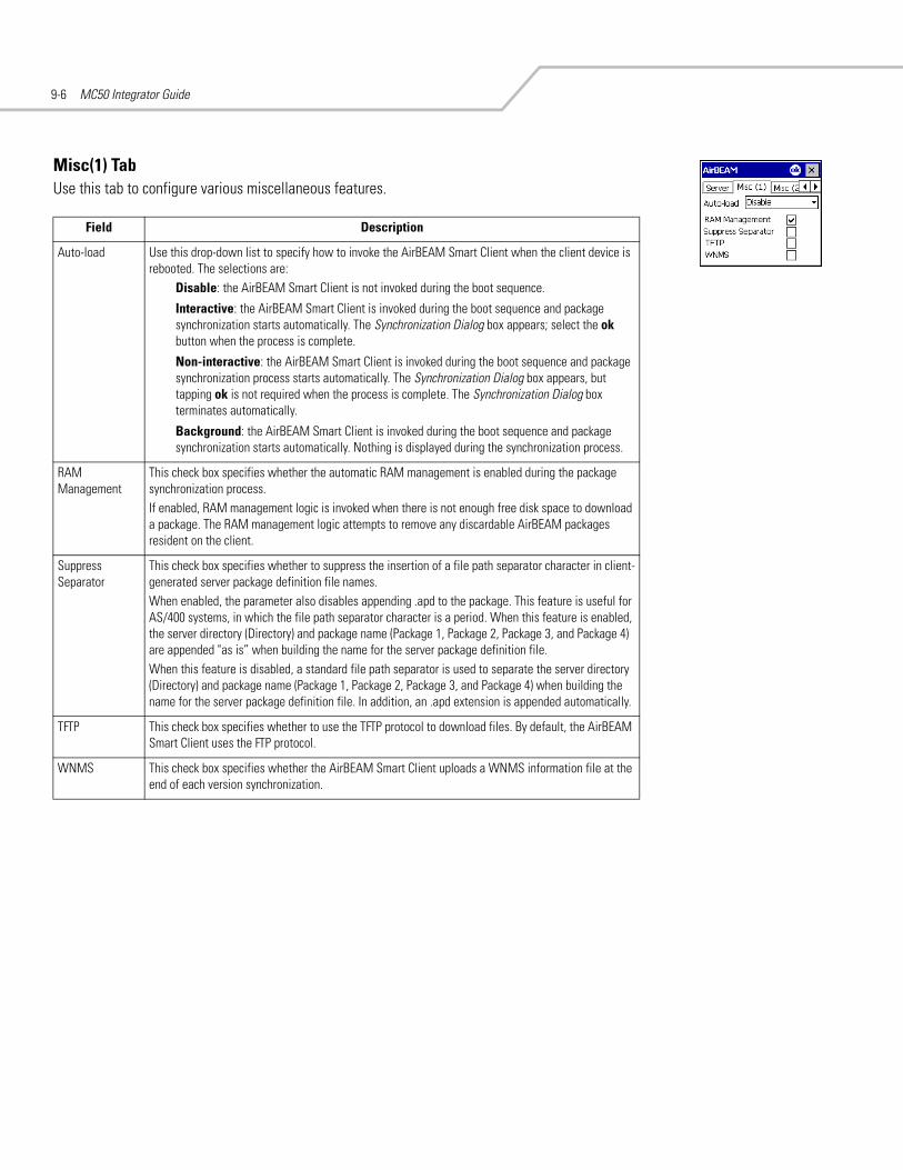
MC50 Integrator Guide9-6
Misc(1) TabUse this tab to configure various miscellaneous features.
Field Description
Auto-load Use this drop-down list to specify how to invoke the AirBEAM Smart Client when the client device is rebooted. The selections are:
Disable: the AirBEAM Smart Client is not invoked during the boot sequence.
Interactive: the AirBEAM Smart Client is invoked during the boot sequence and package synchronization starts automatically. The Synchronization Dialog box appears; select the ok button when the process is complete.
Non-interactive: the AirBEAM Smart Client is invoked during the boot sequence and package synchronization process starts automatically. The Synchronization Dialog box appears, but tapping ok is not required when the process is complete. The Synchronization Dialog box terminates automatically.
Background: the AirBEAM Smart Client is invoked during the boot sequence and package synchronization starts automatically. Nothing is displayed during the synchronization process.
RAM Management
This check box specifies whether the automatic RAM management is enabled during the package synchronization process. If enabled, RAM management logic is invoked when there is not enough free disk space to download a package. The RAM management logic attempts to remove any discardable AirBEAM packages resident on the client.
Suppress Separator
This check box specifies whether to suppress the insertion of a file path separator character in client-generated server package definition file names.When enabled, the parameter also disables appending .apd to the package. This feature is useful for AS/400 systems, in which the file path separator character is a period. When this feature is enabled, the server directory (Directory) and package name (Package 1, Package 2, Package 3, and Package 4) are appended "as is” when building the name for the server package definition file. When this feature is disabled, a standard file path separator is used to separate the server directory (Directory) and package name (Package 1, Package 2, Package 3, and Package 4) when building the name for the server package definition file. In addition, an .apd extension is appended automatically.
TFTP This check box specifies whether to use the TFTP protocol to download files. By default, the AirBEAM Smart Client uses the FTP protocol.
WNMS This check box specifies whether the AirBEAM Smart Client uploads a WNMS information file at the end of each version synchronization.

AirBEAM Smart 9-7
Misc(2) TabUse this tab to configure various miscellaneous features.
Misc(3) TabUse this tab to configure various miscellaneous features.
Field Description
Auto-retry Use this field to specify whether the AirBEAM Smart Client automatically retries if there is a failure during the synchronization process. If enabled, the AirBEAM Smart Client displays a popup dialog indicating a retry attempt. The popup dialog is displayed for the number of seconds specified in the Retry Delay field. The valid values for this field are:
-1: the AirBEAM Smart Client retries indefinitely.
0: the AirBEAM Smart Client does not retry.
-0: the AirBEAM Smart Client retries up to the number of times specified.
Retry Delay This field specifies the amount of time, in seconds, that the AirBEAM Smart Client delays before automatically retrying after a synchronization failure.
In-use Test This check box specifies whether the AirBEAM Smart Client tests to determine if a file is in use before downloading. If the In-use Test feature is enabled, the AirBEAM Smart Client downloads a temporary copy of any files that are in use. If any temporary in-use files are downloaded the AirBEAM Smart Client automatically resets the client to complete the copy of the in-use files. If the In-use Test feature is disabled, the synchronization process fails (-813) if any download files are in use.
Wait Welcome This check box specifies whether the AirBEAM Smart Client waits for the WELCOME windows to complete before launching synchronization after a reset.
Close Apps This check box specifies whether the AirBEAM Smart Client automatically attempts to close non-system applications prior to resetting the mobile unit. If enabled the AirBEAM Smart Client sends a WM_CLOSE message to all non-system applications before resetting the mobile unit. This feature offers applications the opportunity to prepare (i.e., close open files) for the pending reset.
Field Description
Use DHCP server This check box control specifies whether the AirBEAM Smart Client uses the DHCP response option 66 to specify the IP address of the FTP/TFTP server.If enabled, special RF network registry settings are required to force the DHCP server to return the "TFTP server name" field (option 66). The special RF network registry settings are included, but commented out, in the radio network registry initialization files (essid_xxxx_yy.reg).
Use DHCP bootfile This check box control specifies whether the AirBEAM Smart Client uses the DHCP response option 67 to specify the Package and Package 1 parameters.If enabled, special RF network registry settings are required to force the DHCP server to return the "Bootfile name" field (option 67). The special RF network registry settings are included, but commented out, in the radio network registry initialization files (essid_xxxx_yy.reg).
Passive Mode Use this checkbox to specify whether the Client uses passive mode FTP. This setting is ignored if TFTP protocol is used.
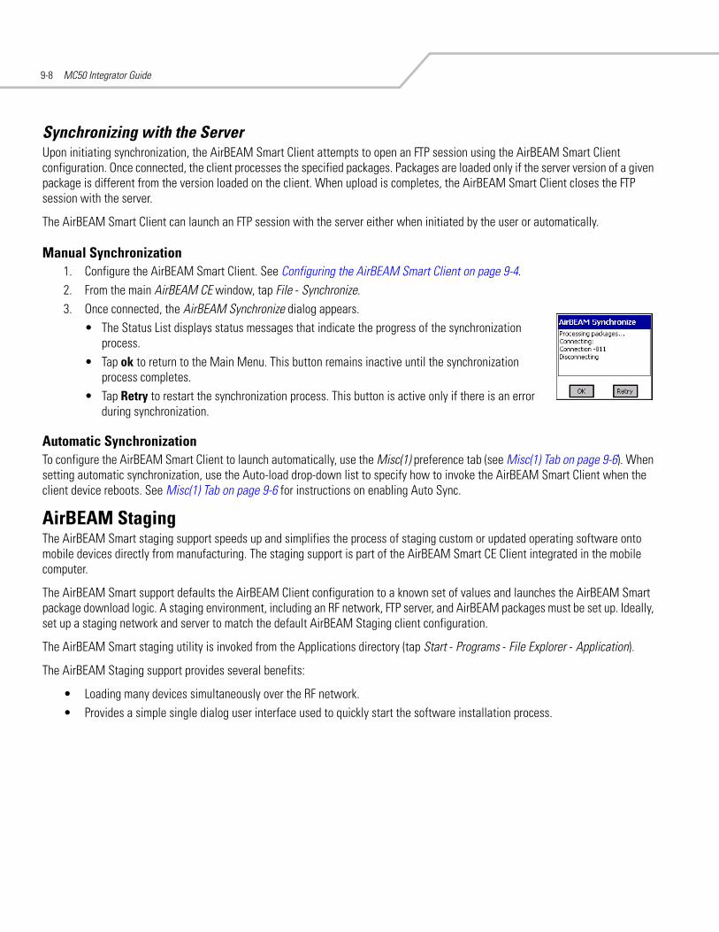
MC50 Integrator Guide9-8
Synchronizing with the ServerUpon initiating synchronization, the AirBEAM Smart Client attempts to open an FTP session using the AirBEAM Smart Client configuration. Once connected, the client processes the specified packages. Packages are loaded only if the server version of a given package is different from the version loaded on the client. When upload is completes, the AirBEAM Smart Client closes the FTP session with the server.
The AirBEAM Smart Client can launch an FTP session with the server either when initiated by the user or automatically.
Manual Synchronization1. Configure the AirBEAM Smart Client. See Configuring the AirBEAM Smart Client on page 9-4.2. From the main AirBEAM CE window, tap File - Synchronize. 3. Once connected, the AirBEAM Synchronize dialog appears.
• The Status List displays status messages that indicate the progress of the synchronization process.
• Tap ok to return to the Main Menu. This button remains inactive until the synchronization process completes.
• Tap Retry to restart the synchronization process. This button is active only if there is an error during synchronization.
Automatic SynchronizationTo configure the AirBEAM Smart Client to launch automatically, use the Misc(1) preference tab (see Misc(1) Tab on page 9-6). When setting automatic synchronization, use the Auto-load drop-down list to specify how to invoke the AirBEAM Smart Client when the client device reboots. See Misc(1) Tab on page 9-6 for instructions on enabling Auto Sync.
AirBEAM StagingThe AirBEAM Smart staging support speeds up and simplifies the process of staging custom or updated operating software onto mobile devices directly from manufacturing. The staging support is part of the AirBEAM Smart CE Client integrated in the mobile computer.
The AirBEAM Smart support defaults the AirBEAM Client configuration to a known set of values and launches the AirBEAM Smart package download logic. A staging environment, including an RF network, FTP server, and AirBEAM packages must be set up. Ideally, set up a staging network and server to match the default AirBEAM Staging client configuration.
The AirBEAM Smart staging utility is invoked from the Applications directory (tap Start - Programs - File Explorer - Application).
The AirBEAM Staging support provides several benefits:
• Loading many devices simultaneously over the RF network.• Provides a simple single dialog user interface used to quickly start the software installation process.

Rapid Deployment Client
Introduction . . . . . . . . . . . . . . . . . . . . . . . . . . . . . . . . . . . . . . . . . . . . . . . . . . . . . . . . . . . . . . . . . . . . . . . . . . . 10-3Rapid Deployment Window . . . . . . . . . . . . . . . . . . . . . . . . . . . . . . . . . . . . . . . . . . . . . . . . . . . . . . . . . . . . . . . . 10-3Scanning RD Bar Codes . . . . . . . . . . . . . . . . . . . . . . . . . . . . . . . . . . . . . . . . . . . . . . . . . . . . . . . . . . . . . . . . . . . 10-5

MC50 Integrator Guide10-2

Rapid Deployment Client 10-3
IntroductionThe Rapid Deployment (RD) Client facilitates software downloads to a mobile computer from a Mobility Services Platform (MSP) Console’s FTP server. The MSP Console is a web-based interface to the wireless infrastructure monitoring and management tools provided by the MSP Lite or MSP Enterprise server.
When software packages are transferred to the FTP server, mobile computers on the wireless network can download them. The location of software packages are encoded in RD bar codes. When the mobile computer scans a bar code(s), the software package(s) is downloaded from the FTP server to the mobile computer. A single RD bar code can be scanned by multiple mobile computers.
For detailed information about the MSP Console, MSP Lite/MSP Enterprise servers, and creating RD bar codes, refer to the MSP Users Guide.
Rapid Deployment WindowThe Rapid Deployment window displays bar code scan status and provides features for resetting and exiting the application.
To access the Rapid Deployment window tap Start - Rapid Deployment Client or Start - Programs - Rapid Deployment Client icon.
Figure 10-1. Rapid Deployment Window

MC50 Integrator Guide10-4
Table 10-1. Rapid Deployment Window
Text Box/Button Description
Please scan all of the bar codes... This text box displays the status of a scanned bar code.Waiting - indicates the mobile computer is ready to scan a bar code.OK - indicates the mobile computer successfully scanned a bar code. (The Indicator LED bar on the mobile computer turns green and a beep sounds).If there are no bar codes left to scan, the Rapid Deployment Configuring window displays. See Figure 10-3.
Bar codes left to scan... This text box displays a list of any remaining bar codes to scan (1-D bar codes only). When all required bar codes are scanned successfully, the Rapid Deployment Configuring window displays. See Figure 10-3.
About Tap About to display the Rapid Deployment Client Info window.
Reset Tap Reset to remove any previously scanned data.
Exit Tap Exit to close the application. A confirmation window displays:
Tap Yes to exit or No to return to the Rapid Deployment window.Note: If the application is exited prior to scanning all required bar codes, any scanned data collected up to that point is lost.

Rapid Deployment Client 10-5
Scanning RD Bar CodesWhen the mobile computer scans and successfully decodes a single or multiple RD bar codes, the data encoded in the bar code can:
• reset the mobile computer’s connection profile. A connection profile is a set of Mobile Companion parameters that the mobile computer uses to access the wireless network.
• initiate downloads of one or more software packages from an FTP server to the mobile computer.
Currently, RD only recognizes AirBEAM software packages. See Chapter 9, AirBEAM Smart for more information.
To scan an RD bar code:
1. Obtain the appropriate RD bar code(s) from the MSP Administrator.2. Launch the RD application on the mobile computer by tapping:
Start - Rapid Deployment Client
or
Start - Programs - Rapid Deployment Client icon.
The Rapid Deployment window displays.
Figure 10-2. Rapid Deployment Window
3. Scan the appropriate bar code(s) to complete the configuration and/or download. For information about scanning with the mobile computer, see the MC50 User Guide.a. A PDF417 bar code (2-D bar code) can contain all download data in a single bar code. In this case, only one bar code may
be required to scan.b. Multi-part linear bar codes (1-D bar codes) can require scanning several bar codes. Bar codes can be scanned in any
order. The text box under Bar codes left to scan... shows the remaining bar codes to scan. See Figure 10-2.
Ready to ScanNo Bar Codes Left to Scan
Ready to ScanBar Codes 1, 10, 11, 12 Left to Scan

MC50 Integrator Guide10-6
4. After all appropriate bar codes are scanned successfully, the mobile computer connects to the server and the Rapid Deployment Configuring window displays while network settings are configured.
Figure 10-3. Rapid Deployment Window - Configuring
If the mobile computer cannot connect to the server, it continues to retry until the user cancels (exits) the application. If failure to connect to the server persists, see the MSP Administrator.
5. When configuration is complete:a. The Today screen displays. See the MC50 User Guide.b. A new Mobile Companion profile is created on the mobile computer from the data encoded in the bar code(s) scanned.
See Mobile Companion on page 8-4 for more information about wireless profiles.c. The designated package(s) are downloaded from the FTP server.

Maintenance & Troubleshooting
Introduction . . . . . . . . . . . . . . . . . . . . . . . . . . . . . . . . . . . . . . . . . . . . . . . . . . . . . . . . . . . . . . . . . . . . . . . . . . . 11-3Maintaining the Mobile Computer. . . . . . . . . . . . . . . . . . . . . . . . . . . . . . . . . . . . . . . . . . . . . . . . . . . . . . . . . . . 11-3Troubleshooting . . . . . . . . . . . . . . . . . . . . . . . . . . . . . . . . . . . . . . . . . . . . . . . . . . . . . . . . . . . . . . . . . . . . . . . . . 11-4
Mobile Computer . . . . . . . . . . . . . . . . . . . . . . . . . . . . . . . . . . . . . . . . . . . . . . . . . . . . . . . . . . . . . . . . . . . . 11-4Four Slot Spare Battery Charger . . . . . . . . . . . . . . . . . . . . . . . . . . . . . . . . . . . . . . . . . . . . . . . . . . . . . . . . 11-5Single Slot USB Cradle . . . . . . . . . . . . . . . . . . . . . . . . . . . . . . . . . . . . . . . . . . . . . . . . . . . . . . . . . . . . . . . 11-6Four Slot USB and Ethernet Cradles . . . . . . . . . . . . . . . . . . . . . . . . . . . . . . . . . . . . . . . . . . . . . . . . . . . . . 11-7Cable Adapter Module . . . . . . . . . . . . . . . . . . . . . . . . . . . . . . . . . . . . . . . . . . . . . . . . . . . . . . . . . . . . . . . . 11-8Magnetic Stripe Reader . . . . . . . . . . . . . . . . . . . . . . . . . . . . . . . . . . . . . . . . . . . . . . . . . . . . . . . . . . . . . . . 11-8

MC50 Integrator Guide11-2
Maintenance & Troubleshooting 11-3
IntroductionThis chapter includes instructions on cleaning and storing the mobile computer, and provides troubleshooting solutions for potential problems during mobile computer operation.
Maintaining the Mobile ComputerFor trouble-free service, observe the following tips when using the mobile computer:
• Do not scratch the screen of the mobile computer. When working with the mobile computer, use the supplied stylus or plastic-tipped pens intended for use with a touch-sensitive screen. Never use an actual pen or pencil or other sharp object on the surface of the mobile computer screen.
Symbol recommends using a screen protector, p/n KT-67525-01.• The mobile computer is not water and dust resistant. Do not expose it to rain or moisture for an extended period of time. In
general, treat the mobile computer as a pocket calculator or other small electronic instrument.• The touch-sensitive screen of the mobile computer is glass. Do not to drop the mobile computer or subject it to strong impact. • Protect the mobile computer from temperature extremes. Do not leave it on the dashboard of a car on a hot day, and keep it
away from heat sources.• Do not store or use the mobile computer in any location that is dusty, damp, or wet.• Use a soft lens cloth to clean the mobile computer. If the surface of the mobile computer screen becomes soiled, clean it
with a soft cloth moistened with a diluted window-cleaning solution.• Periodically replace the rechargeable battery to ensure maximum battery life and product performance. Battery life depends
on individual usage patterns.• The MC50 battery requires periodic calibration to maintain an accurate calibration of the battery's gas gauge. To calibrate
the battery, deplete the battery completely from a full charge condition. Symbol recommends performing this once a week.

MC50 Integrator Guide11-4
Troubleshooting
Mobile ComputerTable 11-1. Troubleshooting the Mobile Computer
Problem Cause Solution
Mobile computer does not turn on.
Lithium-ion battery not charged.
Charge or replace the lithium-ion battery in the mobile computer.
Lithium-ion battery not installed properly.
Ensure battery is installed properly. See Installing and Removing the Main Battery on page 1-5.
System crash. Perform a warm boot. If the mobile computer still does not turn on, perform a cold boot. See Resetting the Mobile Computer on page 1-7.
Rechargeable lithium-ion battery did not charge.
Battery failed. Replace battery. If the mobile computer still does not operate, try a warm boot, then a cold boot. See Resetting the Mobile Computer on page 1-7.
Mobile computer removed from cradle while battery was charging.
Insert mobile computer in cradle and begin charging. The standard battery requires approximately 3.5 hours and the extended capacity battery requires approximately seven hours to charge.
Cannot see characters on display. Mobile computer not powered on.
Press the Power button.
During data communication, no data was transmitted, or transmitted data was incomplete.
Mobile computer removed from cradle or unplugged from host computer during communication.
Replace the mobile computer in the cradle, or reattach the CAM data cable and re-transmit.
Incorrect cable configuration. See the System Administrator.
Communication software was incorrectly installed or configured.
Perform setup as described in Chapter 3, ActiveSync.
Mobile computer does not emit sound.
Volume setting is low or turned off.
Unit may be a beeper only unit or incorrect Config Block is programmed into device.
Mobile computer turns itself off. Mobile computer is inactive. The mobile computer turns off after a period of inactivity. This period can be set from 1 to 5 minutes, in one-minute intervals.Check the Power window by selecting Start - Settings - System tab - Power icon - Advanced tab. Change the setting for a longer delay before the automatic shutoff feature activates.
Battery is not inserted properly.
Insert the battery properly. See Installing and Removing the Main Battery on page 1-5.
Battery is depleted. Recharge or replace the battery.
Battery has exhausted its usable life.
Replace the battery.
Battery’s gas gauge has lost calibration.
Re-calibrate the battery. See Calibrating the Battery on page 1-7.
Pressing keys or buttons does not activate the corresponding feature.
Keypad is locked. Place the keypad lock switch into the unlocked position.
Tapping the window buttons or icons does not activate the corresponding feature.
LCD screen not aligned correctly.
Re-calibrate the screen. See the Microsoft Windows Mobile 2003 for Pocket PC User Guide, p/n 72E-68197-xx.
The system is not responding. Warm boot the system.See Resetting the Mobile Computer on page 1-7.

Maintenance & Troubleshooting 11-5
Four Slot Spare Battery Charger
A message appears stating that the mobile computer memory is full.
Too many files stored on the mobile computer.
Delete unused memos and records. If necessary, save these records on the host computer.
Too many applications installed on the mobile computer.
Remove unused installed applications from the mobile computer to recover memory. Select Start - Settings - System tab and tap the Remove Programs icon. Select the unused program and tap Remove.
The mobile computer does not accept scan input. (Doesnot apply to camera configurations.)
Scanning application is not loaded.
Verify that the mobile computer is loaded with a scanning application. See the System Administrator.
Unreadable bar code. Ensure the symbol is not defaced.
Distance between exit window and bar code is incorrect.
Ensure mobile computer is within proper scanning range.
Mobile computer is not programmed for the bar code type.
Ensure the mobile computer is programmed to accept the type of bar code scanned.
Mobile computer is not programmed to generate a beep.
If a beep on a good decode is expected and a beep is not heard, check that the application is set to generate a beep on good decode.
Battery is low. If the scanner stops emitting a laser beam or aiming pattern upon a trigger press, check the battery level. When the battery is low, the scanner shuts off before the mobile computer low battery condition notification. Note: If the scanner is still not reading symbols, contact the distributor or Symbol Technologies.
Table 11-2. Troubleshooting the Four Slot Spare Battery Charger
Symptom Possible Cause Action
Battery not charging. Battery was removed from the charger or charger was unplugged from AC power too soon.
Re-insert the battery in the charger or re-connect the charger’s power supply.
Battery is faulty. Verify that other batteries charge properly. If so, replace the faulty battery.
Battery contacts not connected to charger.
Verify that the battery is seated in the battery well correctly with the contacts facing down.
Table 11-1. Troubleshooting the Mobile Computer (Continued)
Problem Cause Solution

MC50 Integrator Guide11-6
Single Slot USB CradleTable 11-3. Troubleshooting the Single Slot USB Cradle
Symptom Possible Cause Action
LEDs do not light when mobile computer or spare battery is inserted.
Cradle is not receiving power. Ensure the power cable is connected securely to both the cradle and to AC power.
Mobile computer is not seated firmly in the cradle.
Remove and re-insert the mobile computer into the cradle, ensuring it is firmly seated.
Spare battery is not seated firmly in the cradle.
Remove and re-insert the spare battery into the charging slot, ensuring it is firmly seated.
Mobile computer battery is not charging.
Mobile computer was removed from cradle or cradle was unplugged from AC power too soon.
Ensure cradle is receiving power. Ensure mobile computer is seated correctly. Confirm main battery is charging under Start - Settings - System - Power. The standard battery requires approximately 3.5 hours and the extended capacity battery requires approximately seven hours to charge.
Battery is faulty. Verify that other batteries charge properly. If so, replace the faulty battery.
The mobile computer is not fully seated in the cradle.
Remove and re-insert the mobile computer into the cradle, ensuring it is firmly seated.
Spare battery is not charging. Battery not fully seated in charging slot.
Remove and re-insert the spare battery into the cradle, ensuring it is firmly seated.
Battery inserted incorrectly. Re-insert the battery so the charging contacts on the battery align with the contacts on the cradle.
Battery is faulty. Verify that other batteries charge properly. If so, replace the faulty battery.
During data communication, no data was transmitted, or transmitted data was incomplete.
Mobile computer removed from cradle during communication.
Replace mobile computer in cradle and retransmit.
Incorrect cable configuration. See the system administrator.
Communication software improperly configured.
Perform setup as described in Chapter 3, ActiveSync.

Maintenance & Troubleshooting 11-7
Four Slot USB and Ethernet CradlesTable 11-4. Troubleshooting the Four Slot USB and Ethernet Cradles
Symptom Cause Solution
Communication Status LED does not light up.
Mobile computer is not inserted correctly in the cradle.
Remove, then reinsert the mobile computer securely.
Cradle is not receiving power. Ensure the power supply is securely connected to both the cradle and AC power.
Battery is not charging. Mobile computer removed from the cradle too soon.
Replace the mobile computer in the cradle. The standard battery requires approximately 3.5 hours and the extended capacity battery requires approximately seven hours to charge. Tap Start - Settings - System - Power to view battery status.
Battery is faulty. Verify that other batteries charge properly. If so, replace the faulty battery.
Mobile computer is not inserted correctly in the cradle.
Remove the mobile computer and reinsert it correctly. Verify charging is active. Tap Start - Settings - System - Power to view battery status.
Attempt by the mobile computer to ActiveSync failed.
Mobile computer removed from the cradle while the LED was blinking green.
Wait one minute and reinsert the mobile computer in the cradle. This allows the cradle to attempt another synchronization.
ActiveSync on the host computer has not yet closed the previous ActiveSync session.
Wait one minute and reinsert the mobile computer in the cradle. This allows the cradle to attempt another synchronization.
Incorrect cable configuration. Ensure the correct cable (USB or Ethernet) is used with the cradle.
Communication software improperly configured.
Perform setup as described in Chapter 3, ActiveSync.
During communication, no data was transmitted, or transmitted data was incomplete.
Mobile computer removed from cradle during communication.
Replace mobile computer in cradle and retransmit.
Mobile computer has no active connection.
An icon is visible in the status bar if a connection is active.

MC50 Integrator Guide11-8
Cable Adapter Module
Magnetic Stripe Reader
Table 11-5. Troubleshooting the Cable Adapter Module
Symptom Possible Cause Action
Mobile computer battery is not charging.
CAM was removed from mobile computer or CAM was unplugged from AC power too soon.
Ensure CAM is attached correctly and receiving power. Confirm main battery is charging under Start - Settings - System - Power. The standard battery requires approximately 3.5 hours and the extended capacity battery requires approximately seven hours to charge.
Battery is faulty. Verify that other batteries charge properly. If so, replace the faulty battery.
CAM is not fully attached to the mobile computer.
Reattach CAM to the mobile computer.
During data communication, no data was transmitted, or transmitted data was incomplete.
CAM removed from mobile computer during communication.
Reattach CAM to mobile computer and retransmit.
Incorrect cable configuration. See the System Administrator.
Communication software is not installed or configured properly.
Perform setup as described in Chapter 3, ActiveSync.
Table 11-6. Troubleshooting the Magnetic Stripe Reader
Symptom Possible Cause Action
MSR does not read card. MSR removed from mobile computer during card swipe.
Reattach MSR to mobile computer and reswipe the card.
Faulty magnetic stripe on card. See the System Administrator.
MSR application is not installed or configured properly.
Ensure the MSR application is installed on the mobile computer. Ensure the MSR application is configured correctly.

Specifications
Technical Specifications . . . . . . . . . . . . . . . . . . . . . . . . . . . . . . . . . . . . . . . . . . . . . . . . . . . . . . . . . . . . . . . . . . A-3MC50 Accessory Specifications . . . . . . . . . . . . . . . . . . . . . . . . . . . . . . . . . . . . . . . . . . . . . . . . . . . . . . . . A-6
COM Port Definitions . . . . . . . . . . . . . . . . . . . . . . . . . . . . . . . . . . . . . . . . . . . . . . . . . . . . . . . . . . . . . . . . . . . . A-10Pin-Outs . . . . . . . . . . . . . . . . . . . . . . . . . . . . . . . . . . . . . . . . . . . . . . . . . . . . . . . . . . . . . . . . . . . . . . . . . . . . . . A-11

MC50 Integrator GuideA-2

Specifications A-3
Technical SpecificationsThe following table summarizes the mobile computer’s intended operating environment and technical hardware specifications.
Table A-1. MC50 Technical Specifications
Feature Description
Dimensions with standard battery:
Navigation Keypad, 1D Scanning 4.75 in. L x 3.00 in. W x 1.12 in. D (12.07 cm L x 7.62 cm W x 2.84 cm D)
Navigation Keypad, 1D & 2D Imaging 4.75 in. L x 3.00 in. W x 1.16 in. D (12.07 cm L x 7.62 cm W x 2.95 cm D)
Navigation Keypad, Camera 4.75 in. L x 3.00 in. W x 0.95 in. D (12.07 cm L x 7.62 cm W x 2.41 cm D)
QWERTY Keypad, 1D Scanning 5.4 in. L x 3.00 in. W x 1.12 in. D (13.71 cm L x 7.62 cm W x 2.84 cm D)
QWERTY Keypad, 1D & 2D Imaging 5.4 in. L x 3.00 in. W x 1.16 in. D (13.71 cm L x 7.62 cm W x 2.95 cm D)
QWERTY Keypad, Camera 5.4 in. L x 3.00 in. W x 0.95 in. D (13.71 cm L x 7.62 cm W x 2.41 cm D)
Dimensions with extended capacity battery:
Navigation Keypad, 1D Scanning 4.75 in. L x 3.00 in. W x 1.12 in. D (12.07 cm L x 7.62 cm W x 2.84 cm D)
Navigation Keypad, 1D & 2D Imaging 4.75 in. L x 3.00 in. W x 1.16 in. D (12.07 cm L x 7.62 cm W x 2.95 cm D)
Navigation Keypad, Camera 4.75 in. L x 3.00 in. W x 1.05 in. D (12.07 cm L x 7.62 cm W x 2.67 cm D)
QWERTY Keypad, 1D Scanning 5.4 in. L x 3.00 in. W x 1.12 in. D (13.71 cm L x 7.62 cm W x 2.84 cm D)
QWERTY Keypad, 1D & 2D Imaging 5.4 in. L x 3.00 in. W x 1.16 in. D (13.71 cm L x 7.62 cm W x 2.95 cm D)
QWERTY Keypad, Camera 5.4 in. L x 3.00 in. W x 1.05 in. D (13.71 cm L x 7.62 cm W x 2.67 cm D)
Weight with standard battery:
Navigation Keypad, 1D Scanning 6.8 oz (192.8 g)
Navigation Keypad, 1D & 2D Imaging 7.2 oz (204.1 g)
Navigation Keypad, Camera 6.9 oz (195.6 g)
QWERTY Keypad, 1D Scanning 7.2 oz (204.1 g)
QWERTY Keypad, 1D & 2D Imaging 7.6 oz (215.5 g)
QWERTY Keypad, Camera 7.3 oz (207.0 g)
Weight with extended capacity battery:
Navigation Keypad, 1D Scanning 8.3 oz (235.3 g)
Navigation Keypad, 1D & 2D Imaging 8.7 oz (246.6 g)
Navigation Keypad, Camera 8.4 oz (238.1 g)
QWERTY Keypad, 1D Scanning 8.7 oz (246.6 g)
QWERTY Keypad, 1D & 2D Imaging 9.1 oz (258.0 g)
QWERTY Keypad, Camera 8.8 oz (249.5 g)
Display 3.5” QVGA transflective color
Touch Panel Resistive touch
Main Battery Standard: Rechargeable Lithium-Ion 3.7 V 1560 mAhExtended Capacity: Rechargeable Lithium-Ion 3.7 V 3600 mAh
Backup Battery Provides 30 minutes backup at room temperature; 5 minutes at temperature extremes

MC50 Integrator GuideA-4
Processor Intel® XScale™ PXA270
Operating Platform Microsoft® Windows® Mobile 2003 Second Edition for Pocket PC
Memory 64 MB RAM/ 64 MB ROM
Interface RS-232, USB Client
Expansion Slot SD/MMC user accessible (SDIO)Options: scanner, camera, memory cards, Bluetooth radio
Keypad Options Navigation keypadQWERTY keypad
Optional Scan Engine 1-D Decode Capability Code 39, Code 128, Code 93, Codabar, Interleaved 2 of 5, Discrete 2 of 5, MSI, UPC/EAN family (EAN-8, EAN-13, EAN-128, UPC-A, UPC-E, UPC/EAN supplementals)
Optional Imaging 1-D and 2-D Decode Capability Code 39, Code 128, Code 93, Codabar, Code 11, Interleaved 2 of 5, Discrete 2 of 5, MSI, UPC/EAN family (EAN-8, EAN-13, EAN-128, UPC-A, UPC-E, UPC/EAN supplementals), Coupon Code, Code 39 Trioptic, Composite Code, PDF417, Micro PDF417, RSS Expanded, RSS Limited, RSS-14, Data Matrix, Maxi Code, QR Code, US Postnet, US Planet, UK 4-state, Australian 4-state, Canadian 4-state, Japanese 4-state, Dutch Kix
Optional Scan Engine Scanning Specifications Print Contrast: Minimum 35% absolute dark/light reflectance measured at 675 nm.Ambient Light Requirements:
Sunlight (max.): 8,000 ft. candles / 86,112 luxAmbient Light (min.): 0.5 ft. candles / 5 lux (color temperature: ~5,000K)
Optional Imaging 1-D and 2-D Scanning Specifications
Ambient Light Requirements (Sunlight): 9,000 ft. candles / 96,900 lux
Printer Support Zebra: QL320, QL420, Cameo family, Encore 3 and 4 inchMonarch: 9460O’Neill: MF2T, MF4T, VMP2000AIT: PT4000
Environmental
Operating Temperature 32° to 122° F (0° to 50° C)
Storage Temperature -13° to 140° F (-25° to 60° C)
Charging Temperature 32° to 104° F (0° to 40° C)
Humidity 5% to 95% non-condensing
Electrostatic Discharge (ESD) +/- 8 kV air+/- 4 kV contact
802.11b (WLAN)
WLAN connectivity IEEE 802.11b
Antenna Internal
Bluetooth Supports commercially available SD Bluetooth cards
Security LEAP, PEAP, WEP (40/128 bit), WPA-PSK, TKIP, EAP/TLS, FIPS 140-2, CCX
Accessories
Cradles Single-Slot USB: charging and USB communicationFour-Slot USB: charging and USB communicationFour-Slot Ethernet: charging and Ethernet communication
Table A-1. MC50 Technical Specifications (Continued)
Feature Description
Specifications A-5
Chargers Four-Slot Spare Battery Charger: charges four spare batteries simultaneouslyUBC Adapter: adapts the UBC for use with MC50 spare batteries
Magstripe Reader (MSR) Adds magstripe reading capabilities.Magnetic stripe format: ANSI, ISO, AAMVA, CA DMV, user-configurable generic formatSwipe speed: 5 to 50 in. /127 to 1270 mm/sec, bi-directional
Cable Adapter Module (CAM) Accommodates AC line cord and autocharge cable for charging, and USB cable for communication
Miscellaneous Headset: for use in noisy environmentsSDIO Card: provides secondary non-volatile storage
Table A-1. MC50 Technical Specifications (Continued)
Feature Description

MC50 Integrator GuideA-6
MC50 Accessory Specifications
Table A-2. Single-Slot USB Cradle Technical Specifications
Feature Description
Dimensions 4.3 in. L x 2.3 in. W x 3.2 in. H (10.92 cm L x 5.84 cm W x 8.13 cm H)
Weight 6.9 oz (196 g)
Power 5.4 V +/- 5%
Interface USB
Operating Temperature 32° to 122° F (0° to 50° C)
Storage Temperature -40° to 158° F (-40° to 70° C)
Charging Temperature 32° to 104° F (0° to 40° C)
Humidity 5% to 95% non-condensing
Drop 30.0 in. (76.2 cm) drops to vinyl tiled concrete at room temperature
Electrostatic Discharge (ESD) +/- 8 kV air+/- 4 kV contact
Table A-3. Four-Slot USB Cradle Technical Specifications
Feature Description
Dimensions 18.0 in. L x 4.0 in. H x 5.0 in. D (45.72 cm H x 10.16 cm W x 12.7 cm D)
Weight 2.38 lb (1079 g)
Power 12 V
Interface USB
Operating Temperature 32° to 122° F (0° to 50° C)
Storage Temperature -40° to 158° F (-40° to 70° C)
Charging Temperature 32° to 104° F (0° to 40° C)
Humidity 5% to 95% non-condensing
Drop 30.0 in. (76.2 cm) drops to vinyl tiled concrete at room temperature
Electrostatic Discharge (ESD) +/- 8 kV air+/- 4 kV contact
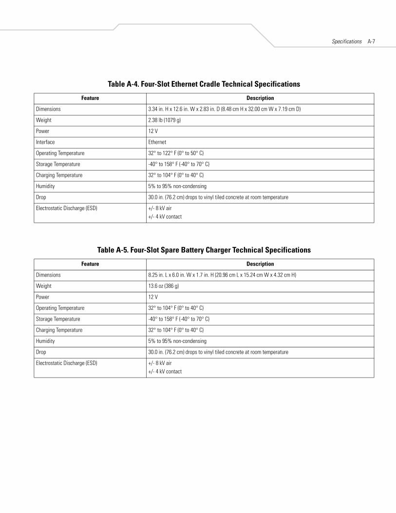
Specifications A-7
Table A-4. Four-Slot Ethernet Cradle Technical Specifications
Feature Description
Dimensions 3.34 in. H x 12.6 in. W x 2.83 in. D (8.48 cm H x 32.00 cm W x 7.19 cm D)
Weight 2.38 lb (1079 g)
Power 12 V
Interface Ethernet
Operating Temperature 32° to 122° F (0° to 50° C)
Storage Temperature -40° to 158° F (-40° to 70° C)
Charging Temperature 32° to 104° F (0° to 40° C)
Humidity 5% to 95% non-condensing
Drop 30.0 in. (76.2 cm) drops to vinyl tiled concrete at room temperature
Electrostatic Discharge (ESD) +/- 8 kV air+/- 4 kV contact
Table A-5. Four-Slot Spare Battery Charger Technical Specifications
Feature Description
Dimensions 8.25 in. L x 6.0 in. W x 1.7 in. H (20.96 cm L x 15.24 cm W x 4.32 cm H)
Weight 13.6 oz (386 g)
Power 12 V
Operating Temperature 32° to 104° F (0° to 40° C)
Storage Temperature -40° to 158° F (-40° to 70° C)
Charging Temperature 32° to 104° F (0° to 40° C)
Humidity 5% to 95% non-condensing
Drop 30.0 in. (76.2 cm) drops to vinyl tiled concrete at room temperature
Electrostatic Discharge (ESD) +/- 8 kV air+/- 4 kV contact

MC50 Integrator GuideA-8
Table A-6. UBC Adapter Technical Specifications
Feature Description
Dimensions 6.1 in. L x 2.9 in. W x 2.3 in. H (15.49 cm L x 7.37 cm W x 5.84 cm H)
Weight 5.2 oz (147 g)
Power 5.4 VDC
Operating Temperature 32° to 122° F (0° to 50° C)
Storage Temperature -40° to 158° F (-40° to 70° C)
Charging Temperature 32° to 104° F (0° to 40° C)
Humidity 5% to 95% non-condensing
Drop 30.0 in. (76.2 cm) drops to vinyl tiled concrete at room temperature
Electrostatic Discharge (ESD) +/- 8 kV air+/- 4 kV contact
Table A-7. Magstripe Reader (MSR) Technical Specifications
Feature Description
Dimensions 2.3 in. L x 3.14 in. W x 1.1 in. H (5.82 cm L x 7.98 cm W x 2.79 cm H)
Weight 1.7 oz (48 g)
Interface Serial with baud rate up to 19,200
Format ANSI, ISO, AAMVA, CA DMV, user-configurable generic format
Swipe Speed 5 to 50 in. (127 to 1270 mm) /sec, bi-directional
Decoders Generic, Raw Data
Mode Buffered, unbuffered
Track Reading Capabilities Tracks 1 and 3: 210 bpiTrack 2: 75 and 210 bpi, autodetect
Operating Temperature 32° to 122° F (0° to 50° C)
Storage Temperature -40° to 158° F (-40° to 70° C)
Humidity 5% to 95% non-condensing
Drop 4 ft. (1.22 m) drops to concrete
Electrostatic Discharge (ESD) +/- 8 kV air+/- 4 kV contact
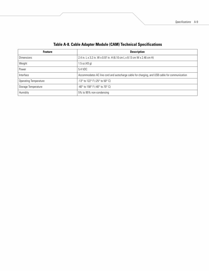
Specifications A-9
Table A-8. Cable Adapter Module (CAM) Technical Specifications
Feature Description
Dimensions 2.4 in. L x 3.2 in. W x 0.97 in. H (6.10 cm L x 8.13 cm W x 2.46 cm H)
Weight 1.5 oz (43 g)
Power 5.4 VDC
Interface Accommodates AC line cord and autocharge cable for charging, and USB cable for communication
Operating Temperature -13° to 122° F (-25° to 50° C)
Storage Temperature -40° to 158° F (-40° to 70° C)
Humidity 5% to 95% non-condensing

MC50 Integrator GuideA-10
COM Port DefinitionsTable A-9. MC50 External COM Connector Definitions
COM Port Definition
COM1 Scanner
COM2 Available
COM3 IRComm
COM4 Raw IrDA
COM5 External Connector
COM6 Available
COM7 Available
COM8 Available
COM9 Available

Specifications A-11
Pin-Outs
Figure A-1. External Connector
Table A-10. External Connector Pin-Outs
Pin Description
1 Power Gnd
2 Not connected
3 Not connected
4 USB_D-
5 USB_D+
6 USB_Gnd
7 USB_Vbus
8 USB_ID
9 RS232_TXD
10 RS232_RXD
11 RS232_RTS
12 RS232_CTS
13 RS232_DTR
14 RS232_DSR
15 External_5.0V
16 External DC In
Pin 1

MC50 Integrator GuideA-12

Keypad Maps
Introduction . . . . . . . . . . . . . . . . . . . . . . . . . . . . . . . . . . . . . . . . . . . . . . . . . . . . . . . . . . . . . . . . . . . . . . . . . . . . B-3Example . . . . . . . . . . . . . . . . . . . . . . . . . . . . . . . . . . . . . . . . . . . . . . . . . . . . . . . . . . . . . . . . . . . . . . . . . . . .B-3
Keypads . . . . . . . . . . . . . . . . . . . . . . . . . . . . . . . . . . . . . . . . . . . . . . . . . . . . . . . . . . . . . . . . . . . . . . . . . . . . . . . .B-4

MC50 Integrator GuideB-2
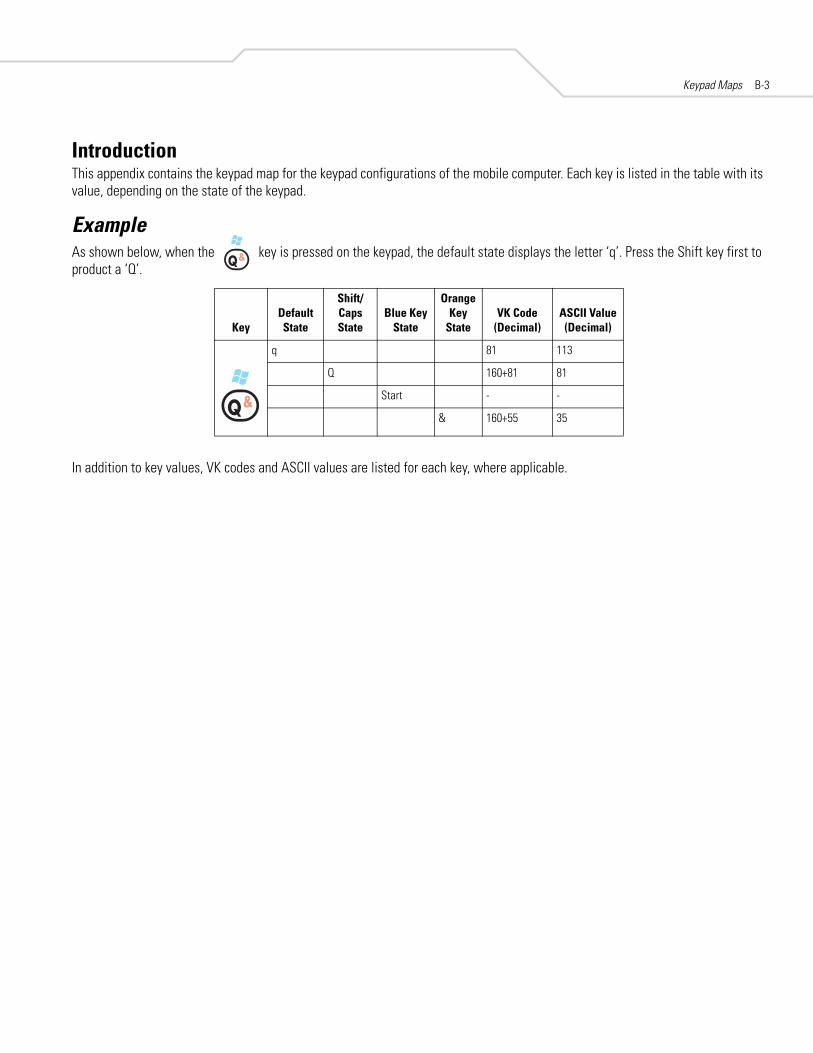
Keypad Maps B-3
IntroductionThis appendix contains the keypad map for the keypad configurations of the mobile computer. Each key is listed in the table with its value, depending on the state of the keypad.
ExampleAs shown below, when the key is pressed on the keypad, the default state displays the letter ‘q’. Press the Shift key first to product a ‘Q’.
In addition to key values, VK codes and ASCII values are listed for each key, where applicable.
KeyDefault State
Shift/Caps State
Blue Key State
Orange Key
StateVK Code
(Decimal)ASCII Value (Decimal)
q 81 113
Q 160+81 81
Start - -
& 160+55 35
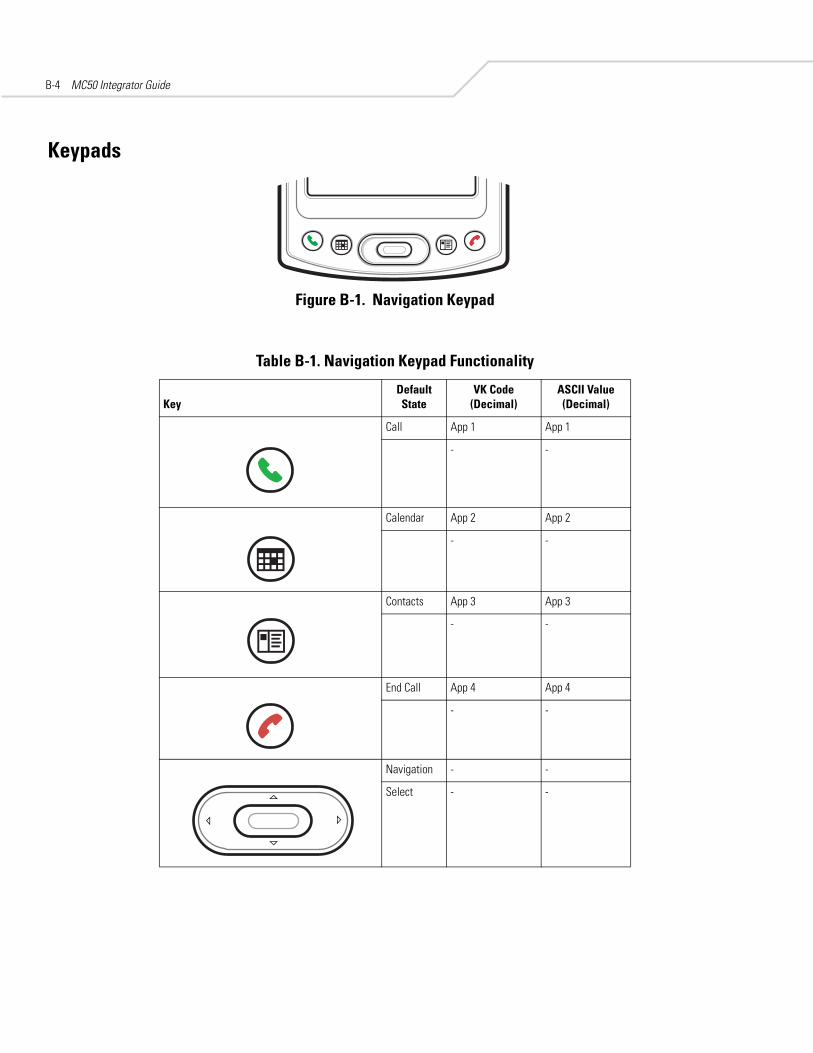
MC50 Integrator GuideB-4
Keypads
Figure B-1. Navigation Keypad
Table B-1. Navigation Keypad Functionality
KeyDefault State
VK Code (Decimal)
ASCII Value (Decimal)
Call App 1 App 1
- -
Calendar App 2 App 2
- -
Contacts App 3 App 3
- -
End Call App 4 App 4
- -
Navigation - -
Select - -

Keypad Maps B-5
Figure B-2. QWERTY Keypad
Table B-2. QWERTY Keypad Functionality
KeyDefault State
Shift/Caps State
Blue Key State
Orange Key
StateVK Code
(Decimal)ASCII Value (Decimal)
q 81 113
Q 160+81 81
Start Menu - -
& 160+55 35
w 87 119
W 160+87 87
Menu - -
$ 160+52 36
e 69 101
E 160+69 69
Messaging - -
@ 160+50 64
r 82 114
R 160+82 82
Calendar - -
% 160+53 37
t 84 116
T 160+84 84
Contacts - -
/ 191 47

MC50 Integrator GuideB-6
y 89 121
Y 160+89 89
Phonepad 198 198
SEND 114 -
u 85 117
U 160+85 85
- -
1 49 49
i 73 105
I 160+73 73
Up Arrow 132 -
2 50 50
o 79 111
O 160+79 79
- -
3 51 51
p 80 112
P 160+80 80
OK/Close - -
END 115 -
a 65 97
A 160+65 65
- -
( - -
s 83 115
S 160+83 83
- -
) 48 41
d 68 100
D 160+68 68
- -
_ 189 95
Table B-2. QWERTY Keypad Functionality (Continued)
KeyDefault State
Shift/Caps State
Blue Key State
Orange Key
StateVK Code
(Decimal)ASCII Value (Decimal)

Keypad Maps B-7
f 70 102
F 160+70 70
- -
: 186 58
g 71 103
G 160+71 71
- -
+ 187 43
h 72 104
H 160+72 72
- -
- 189 45
j 74 106
J 160+74 74
Left Arrow 37 -
4 52 52
k 75 107
K 160+75 75
Select 13 -
5 53 53
l 76 108
L 160+76 76
Right Arrow 39 -
6 54 54
Backspace 8 8
- -
- -
Delete 46 46
Shift 16 -
- -
- -
CAPS - -
Table B-2. QWERTY Keypad Functionality (Continued)
KeyDefault State
Shift/Caps State
Blue Key State
Orange Key
StateVK Code
(Decimal)ASCII Value (Decimal)

MC50 Integrator GuideB-8
z 90 122
Z 160+90 90
- -
? 191 63
x 88 120
X 160+88 88
- -
! 49 33
c 67 99
C 160+67 67
- -
‘ - 39
v 86 118
V 160+86 86
- -
“ 222 34
b 66 98
B 160+66 66
- -
= 187 61
n 78 110
N 160+78 78
- -
7 55 55
m 77 109
M 160+77 77
Down Arrow 40 -
8 56 56
, (comma) 188 44
< 188 60
- -
9 57 57
Table B-2. QWERTY Keypad Functionality (Continued)
KeyDefault State
Shift/Caps State
Blue Key State
Orange Key
StateVK Code
(Decimal)ASCII Value (Decimal)

Keypad Maps B-9
Backlight - -
- -
- -
áü/Sym 122 -
TAB 9 9
- -
- -
Back Tab 160+9 9
Star - -
- -
- -
* 56 42
. 190 46
> 160+190 62
- -
0 48 48
Return (Enter)
13 13
- -
- -
# 160+51 35
Table B-2. QWERTY Keypad Functionality (Continued)
KeyDefault State
Shift/Caps State
Blue Key State
Orange Key
StateVK Code
(Decimal)ASCII Value (Decimal)

MC50 Integrator GuideB-10

Glossary
802.11/802.11b A radio protocol that may be used by the Symbol Spectrum24 radio card. Symbol radio cards that use the 802.11 protocol also have an ESS_ID.
Access Point Access Point (AP) refers to Symbol’s Spectrum24 Ethernet Access Point. It is a piece of communications equipment that manages communications between the host computer system and one or more wireless terminals. An AP connects to a wired Ethernet LAN and acts as a bridge between the Ethernet wired network and IEEE 802.11 interoperable radio-equipped mobile units, such as a mobile computer. The AP allows a mobile user to roam freely through a facility while maintaining a seamless connection to the wired network.

MC50 Integrator GuideGL-2
AirBEAM® Manager AirBEAM® Manager is a comprehensive wireless network management system that provides essential functions that are required to configure, monitor, upgrade and troubleshoot the Spectrum24® wireless network and its components (including networked mobile computers). Some features include event notification, access point configuration, diagnostics, statistical reports, auto-discovery, wireless proxy agents and monitoring of access points and mobile units.
AirBEAM® Smart Client AirBEAM® Smart Client is part of Symbol’s AirBEAM® suite, which also includes AirBEAM® Safe and AirBEAM® Manager. The AirBEAM® Smart Client system uses the network accessible host server to store software files that are to be downloaded to the mobile computers. The AirBEAM® Smart Client provides the mobile computers with the "smarts" to request software from the host. It allows them to request, download and install software, as well as to upload files and status data. The AirBEAM® Smart Client uses the industry standard FTP or TFTP file transfer protocols to check the host system for updates, and if necessary, to transfer updated software. Most often, AirBEAM® Smart Client is used with wireless networks, but any TCP/IP connection can be used. For more information, refer to the AirBEAM® Smart Windows® CE Client Product Reference Guide (p/n 72-63060-xx).
AP See Access Point.
API An interface by means of which one software component communicates with or controls another. Usually used to refer to services provided by one software component to another, usually via software interrupts or function calls
Aperture The opening in an optical system defined by a lens or baffle that establishes the field of view.
Application Programming Interface See API.
ANSI Terminal A display terminal that follows commands in the ANSI standard terminal language. For example, it uses escape sequences to control the cursor, clear the screen and set colors. Communications programs support the ANSI terminal mode and often default to this terminal emulation for dial-up connections to online services.
ASCII American Standard Code for Information Interchange. A 7 bit-plus-parity code representing 128 letters, numerals, punctuation marks and control characters. It is a standard data transmission code in the U.S.
Autodiscrimination The ability of an interface controller to determine the code type of a scanned bar code. After this determination is made, the information content is decoded.
Bar The dark element in a printed bar code symbol.
Glossary GL-3
Bar Code A pattern of variable-width bars and spaces which represents numeric or alphanumeric data in machine-readable form. The general format of a bar code symbol consists of a leading margin, start character, data or message character, check character (if any), stop character, and trailing margin. Within this framework, each recognizable symbology uses its own unique format. See Symbology.
Bar Code Density The number of characters represented per unit of measurement (e.g., characters per inch).
Bar Height The dimension of a bar measured perpendicular to the bar width.
Bar Width Thickness of a bar measured from the edge closest to the symbol start character to the trailing edge of the same bar.
BIOS Basic Input Output System. A collection of ROM-based code with a standard API used to interface with standard PC hardware.
Bit Binary digit. One bit is the basic unit of binary information. Generally, eight consecutive bits compose one byte of data. The pattern of 0 and 1 values within the byte determines its meaning.
Bits per Second (bps) Bits transmitted or received.
Bit Binary digit. One bit is the basic unit of binary information. Generally, eight consecutive bits compose one byte of data. The pattern of 0 and 1 values within the byte determines its meaning.
bps See Bits Per Second.
Byte On an addressable boundary, eight adjacent binary digits (0 and 1) combined in a pattern to represent a specific character or numeric value. Bits are numbered from the right, 0 through 7, with bit 0 the low-order bit. One byte in memory is used to store one ASCII character.
BOOTP A protocol for remote booting of diskless devices. Assigns an IP address to a machine and may specify a boot file. The client sends a bootp request as a broadcast to the bootp server port (67) and the bootp server responds using the bootp client port (68). The bootp server must have a table of all devices, associated MAC addresses and IP addresses.
boot or boot-up The process a computer goes through when it starts. During boot-up, the computer can run self-diagnostic tests and configure hardware and software.
CDMA Code Division Multiple Access. Digital cellular phone service method that separates multiple transmissions over a finite frequency allocation using Spread Spectrum techniques.
CDRH Center for Devices and Radiological Health. A federal agency responsible for regulating laser product safety. This agency specifies various laser operation classes based on power output during operation.

MC50 Integrator GuideGL-4
CDRH Class 1 This is the lowest power CDRH laser classification. This class is considered intrinsically safe, even if all laser output were directed into the eye's pupil. There are no special operating procedures for this class.
CDRH Class 2 No additional software mechanisms are needed to conform to this limit. Laser operation in this class poses no danger for unintentional direct human exposure.
Cellular Digital Packet Data See CDPD.
Character A pattern of bars and spaces which either directly represents data or indicates a control function, such as a number, letter, punctuation mark, or communications control contained in a message.
Character Set Those characters available for encoding in a particular bar code symbology.
Check Digit A digit used to verify a correct symbol decode. The scanner inserts the decoded data into an arithmetic formula and checks that the resulting number matches the encoded check digit. Check digits are required for UPC but are optional for other symbologies. Using check digits decreases the chance of substitution errors when a symbol is decoded.
Codabar A discrete self-checking code with a character set consisting of digits 0 to 9 and six additional characters: ( - $ : / , +).
Code 128 A high density symbology which allows the controller to encode all 128 ASCII characters without adding extra symbol elements.
Code 3 of 9 (Code 39) A versatile and widely used alphanumeric bar code symbology with a set of 43 character types, including all uppercase letters, numerals from 0 to 9 and 7 special characters (- . / + % $ and space). The code name is derived from the fact that 3 of 9 elements representing a character are wide, while the remaining 6 are narrow.
Code 93 An industrial symbology compatible with Code 39 but offering a full character ASCII set and a higher coding density than Code 39.
Code Length Number of data characters in a bar code between the start and stop characters, not including those characters.
Cold Boot A cold boot restarts the mobile computer and erases all user stored records and entries.
COM port Communication port; ports are identified by number, e.g., COM1, COM2.
Continuous Code A bar code or symbol in which all spaces within the symbol are parts of characters. There are no intercharacter gaps in a continuous code. The absence of gaps allows for greater information density.
Cradle A cradle is used for charging the terminal battery and for communicating with a host computer, and provides a storage place for the terminal when not in use.

Glossary GL-5
Data Communications Equipment (DCE) A device (such as a modem) which is designed to attach directly to a DTE (Data Terminal Equipment) device.
DCE See Data Communications Equipment.
DCP See Device Configuration Package.
Dead Zone An area within a scanner's field of view, in which specular reflection may prevent a successful decode.
Decode To recognize a bar code symbology (e.g., UPC/EAN) and then analyze the content of the specific bar code scanned.
Decode Algorithm A decoding scheme that converts pulse widths into data representation of the letters or numbers encoded within a bar code symbol.
Decryption Decryption is the decoding and unscrambling of received encrypted data. Also see, Encryption and Key.
Depth of Field The range between minimum and maximum distances at which a scanner can read a symbol with a certain minimum element width.
Device Configuration Package The Symbol Device Configuration Package provides the Product Reference Guide (PRG), flash partitions, Terminal Configuration Manager (TCM) and the associated TCM scripts. With this package hex images that represent flash partitions can be created and downloaded to the mobile computer.
DHCP (Dynamic Host Configuration Protocol) Software that automatically assigns IP addresses to client stations logging onto a TCP/IP network. Similar to BOOTP, but also permits the leasing of an IP address. It eliminates having to manually assign permanent IP addresses. DHCP software typically runs in servers and is also found in network devices such as routers that allow multiple users access to the Internet.
DHCP Server A server in the network or a service within a server that assigns IP addresses.
Discrete Code A bar code or symbol in which the spaces between characters (intercharacter gaps) are not part of the code.
Discrete 2 of 5 A binary bar code symbology representing each character by a group of five bars, two of which are wide. The location of wide bars in the group determines which character is encoded; spaces are insignificant. Only numeric characters (0 to 9) and START/STOP characters may be encoded.
DNS Server The Control Panel allows you to set the IP address for a DNS Server, if used. This allows users to use server names, rather than IP addresses. It is set on the Network tab of the Control Panel.
Domain Name The Control Panel allows you to set a Domain Name for the DNS Server, if used (e.g., symbol.com). It is set on the Network tab of the Control Panel.
DOS Disk Operating System. This is basic software that allows you to load and use software applications on your computer. Also see NetID.
MC50 Integrator GuideGL-6
DRAM Dynamic random access memory.
DTE See Data Terminal Equipment.
EAN European Article Number. This European/International version of the UPC provides its own coding format and symbology standards. Element dimensions are specified metrically. EAN is used primarily in retail.
Element Generic term for a bar or space.
Encoded Area Total linear dimension occupied by all characters of a code pattern, including start/stop characters and data.
ENQ (RS-232) ENQ software handshaking is also supported for the data sent to the host.
Encryption Encryption is the scrambling and coding of data, typically using mathematical formulas called algorithms, before information is transmitted over any communications link or network. A key is the specific code used by the algorithm to encrypt or decrypt the data. Also see, Decryption and Key.
ESD Electro-Static Discharge
ESN Electronic Serial Number. The unique hardware number associated with a cellular device, which is transmitted to the system when the device communicates witht he celllular system.
ESS_ID Extended Service Set Identifier, defines the coverage area. Prior to the release of the 802.11 specification the ESS_ID was called the Net_ID or Network Identifier. For terminals using Spectrum24 radios with the 802.11 protocol, an ESS_ID allows facilities to limit which Access Points a mobile computer can communicate with. It is set on the Network tab of the Control Panel. The terminal can only communicate with Spectrum24 Access Points that have matching ESS_IDs.
Ethernet Ethernet communication port. Allows a wired interface to a radio network.
Flash Disk An additional megabyte of non-volatile memory for storing application and configuration files.
Flash Memory Flash memory is nonvolatile, semi-permanent storage that can be electronically erased in the circuit and reprogrammed. Series 9000 mobile computers use Flash memory to store the operating system (ROM-DOS), the terminal emulators, and the Citrix ICA Client for DOS.
File Transfer Protocol (FTP) A TCP/IP application protocol governing file transfer via network or telephone lines. See TCP/IP.
Frequency Hopping The use of a random sequence of frequency channels to achieve spread spectrum compliance. Stations that use frequency hopping change their communications frequency at regular intervals. A hopping sequence determines the pattern at which frequencies are changed. Messages take place within a hop. See Hopping Sequence and Spread Spectrum.
FTP See File Transfer Protocol.

Glossary GL-7
Flash Memory Flash memory is responsible for storing the system firmware and is non-volatile. If the system power is interrupted the data is not be lost.
Gateway Address An IP address for a network gateway or router. A mobile computer may be part of a subnet as specified by its IP address and Netmask. It can send packets directly to any node on the same subnet. If the destination node is on a different subnet, then the terminal sends the packet to the gateway first. The gateway determines how to route the packet to the destination subnet. This field is an option used by networks that require gateways.
Hard Reset See Cold Boot.
Hopping Sequence A set of random frequencies designed to minimize interference with other sets of random frequencies. A hopping sequence determines the pattern with which a station that uses frequency hopping changes its communications frequency. See Frequency Hopping.
Hz Hertz; A unit of frequency equal to one cycle per second.
Host Computer A computer that serves other terminals in a network, providing such services as computation, database access, supervisory programs and network control.
IDE Intelligent drive electronics. Refers to the solid-state hard drive type.
IEC International Electrotechnical Commission. This international agency regulates laser safety by specifying various laser operation classes based on power output during operation.
IEC (825) Class 1 This is the lowest power IEC laser classification. Conformity is ensured through a software restriction of 120 seconds of laser operation within any 1000 second window and an automatic laser shutdown if the scanner's oscillating mirror fails.
IEEE Address See MAC Address.
Interleaved 2 of 5 A binary bar code symbology representing character pairs in groups of five bars and five interleaved spaces. Interleaving provides for greater information density. The location of wide elements (bar/spaces) within each group determines which characters are encoded. This continuous code type uses no intercharacter spaces. Only numeric (0 to 9) and START/STOP characters may be encoded.
IOCTL Input/Output Control.
imaging scanning Mobile computers with an integrated imager use digital camera technology to take a digital picture of a bar code, store the resulting image in memory and execute state-of-the-art software decoding algorithms to extract the data from the image.
Intercharacter Gap The space between two adjacent bar code characters in a discrete code.

MC50 Integrator GuideGL-8
Interleaved Bar Code A bar code in which characters are paired together, using bars to represent the first character and the intervening spaces to represent the second.
Interleaved 2 of 5 A binary bar code symbology representing character pairs in groups of five bars and five interleaved spaces. Interleaving provides for greater information density. The location of wide elements (bar/spaces) within each group determines which characters are encoded. This continuous code type uses no intercharacter spaces. Only numeric (0 to 9) and START/STOP characters may be encoded.
Internet Protocol Address See IP.
I/O Ports interface The connection between two devices, defined by common physical characteristics, signal characteristics, and signal meanings. Types of interfaces include RS-232 and PCMCIA.
Input/Output Ports I/O ports are primarily dedicated to passing information into or out of the terminal’s memory. Series 9000 mobile computers include Serial and USB ports.
IP Internet Protocol. The IP part of the TCP/IP communications protocol. IP implements the network layer (layer 3) of the protocol, which contains a network address and is used to route a message to a different network or subnetwork. IP accepts “packets” from the layer 4 transport protocol (TCP or UDP), adds its own header to it and delivers a “datagram” to the layer 2 data link protocol. It may also break the packet into fragments to support the maximum transmission unit (MTU) of the network.
IP Address (Internet Protocol address) The address of a computer attached to an IP network. Every client and server station must have a unique IP address. A 32-bit address used by a computer on a IP network. Client workstations have either a permanent address or one that is dynamically assigned to them each session. IP addresses are written as four sets of numbers separated by periods; for example, 204.171.64.2.
IPX/SPX Internet Package Exchange/Sequential Packet Exchange. A communications protocol for Novell. IPX is Novell’s Layer 3 protocol, similar to XNS and IP, and used in NetWare networks. SPX is Novell's version of the Xerox SPP protocol.
IS-95 Interim Standard 95. The EIA/TIA standard that governs the operation of CDMA cellular service. Versions include IS-95A and IS-95B. See CDMA.
Kerberos Kerberos is a network authentication protocol. It is designed to provide strong authentication for client/server applications by using secret-key cryptography. A free implementation of this protocol is available from the Massachusetts Institute of Technology. Kerberos is available in many commercial products as well.
Key A key is the specific code used by the algorithm to encrypt or decrypt the data. Also see, Encryption and Decrypting.
LAN Local area network. A radio network that supports data communication within a local area, such as within a warehouse of building.

Glossary GL-9
laser scanner A type of bar code reader that uses a beam of laser light.
LASER Light Amplification by Stimulated Emission of Radiation.The laser is an intense light source. Light from a laser is all the same frequency, unlike the output of an incandescent bulb. Laser light is typically coherent and has a high energy density.
Laser Diode A gallium-arsenide semiconductor type of laser connected to a power source to generate a laser beam. This laser type is a compact source of coherent light.
LCD See Liquid Crystal Display.
LED Indicator A semiconductor diode (LED - Light Emitting Diode) used as an indicator, often in digital displays. The semiconductor uses applied voltage to produce light of a certain frequency determined by the semiconductor's particular chemical composition.
Liquid Crystal Display (LCD) A display that uses liquid crystal sealed between two glass plates. The crystals are excited by precise electrical charges, causing them to reflect light outside according to their bias. They use little electricity and react relatively quickly. They require external light to reflect their information to the user.
Light Emitting Diode See LED.
MAC Address (also called IEEE Address) Spectrum24® devices, like other Ethernet devices, have unique, hardware-encoded MAC (also called IEEE addresses). MAC addresses determine the device sending or receiving data. The MAC address is a 48-bit number written as six hexadecimal bytes separated by colons.
MC Mobile Computer.
MDN Mobile Directory Number. The directory listing telephone number that is dialed (generally using POTS) to reach a mobile unit. The MDN is usually associated with a MIN in a cellular telephone -- in the US and Canada, the MDN and MIN are the same value for voice cellular users. International roaming considerations often result in the MDN being different from the MIN.
MIL 1 mil = 1 thousandth of an inch.
MIN Mobile Identification Number. The unique account number associated with a cellular device. It is broadcast by the cellular device when accessing the cellular system.
Misread (Misdecode) A condition which occurs when the data output of a reader or interface controller does not agree with the data encoded within a bar code symbol.
Mobile Computer In this text, mobile computer refers to the Symbol Series 9000 wireless portable computer. It can be set up to run as a stand-alone device, or it can be set up to communicate with a network, using wireless radio technology.
NCU Network Control Unit.
NetBeui A non-routable LAN protocol that is an extension to NetBIOS. Used for IBM’s OS/2-based LAN Manager and Microsoft’s LAN Manager and Windows for Workgroups.

MC50 Integrator GuideGL-10
NetID For terminals using Spectrum24 radios with the Spring protocol, a NetID allows facilities to limit which Access Points a mobile computer can communicate with. It is set on the Network tab of the Control Panel. The terminal can only communicate with Spectrum24 Access Points that have matching NetIDs. Also see ESS_ID.
Nominal The exact (or ideal) intended value for a specified parameter. Tolerances are specified as positive and negative deviations from this value.
Nominal Size Standard size for a bar code symbol. Most UPC/EAN codes are used over a range of magnifications (e.g., from 0.80 to 2.00 of nominal).
NVM Non-Volatile Memory.
ODI See Open Data-Link Interface.
Open Data-Link Interface (ODI) Novell’s driver specification for an interface between network hardware and higher-level protocols. It supports multiple protocols on a single NIC (Network Interface Controller). It is capable of understanding and translating any network information or request sent by any other ODI-compatible protocol into something a NetWare client can understand and process.
Open System Authentication Open System authentication is a null authentication algorithm.
PAN Personal area network. Using Bluetooth wireless technology, PANs enable devices to communicate wirelessly. Generally, a wireless PAN consists of a dynamic group of less than 255 devices that communicate within about a 33-foot range. Only devices within this limited area typically participate in the network.
Parameter A variable that can have different values assigned to it.
PC Card A plug-in expansion card for laptop computers and other devices, also called a PCMCIA card. PC Cards are 85.6mm long x 54 mm wide, and have a 68 pin connector. There are several different kinds:Type I; 3.3 mm high; use - RAM or Flash RAMType II; 5 mm high; use - modems, LAN adaptorsType III; 10.5 high; use - Hard Disks
PCMCIA Personal Computer Memory Card Interface Association. See PC Card.
PDT Portable Data Terminal.
Percent Decode The average probability that a single scan of a bar code would result in a successful decode. In a well-designed bar code scanning system, that probability should approach near 100%.
PING (Packet Internet Groper) An Internet utility used to determine whether a particular IP address is online. It is used to test and debug a network by sending out a packet and waiting for a response.

Glossary GL-11
Print Contrast Signal (PCS) Measurement of the contrast (brightness difference) between the bars and spaces of a symbol. A minimum PCS value is needed for a bar code symbol to be scannable. PCS = (RL - RD) / RL, where RL is the reflectance factor of the background and RD the reflectance factor of the dark bars.
Programming Mode The state in which a scanner is configured for parameter values. See Scanning Mode.
Quiet Zone A clear space, containing no dark marks, which precedes the start character of a bar code symbol and follows the stop character.
QWERTY A standard keyboard commonly used on North American and some European PC keyboards. “QWERTY” refers to the arrangement of keys on the left side of the third row of keys.
RAM Random Access Memory. Data in RAM can be accessed in random order, and quickly written and read.
Reflectance Amount of light returned from an illuminated surface.
Resolution The narrowest element dimension which is distinguished by a particular reading device or printed with a particular device or method.
RF Radio Frequency.
ROM Read-Only Memory. Data stored in ROM cannot be changed or removed.
ROM-DOS The name of the licensed Disk Operating System loaded into the terminal’s flash file system.
Router A device that connects networks and supports the required protocols for packet filtering. Routers are typically used to extend the range of cabling and to organize the topology of a network into subnets. See Subnet.
RS-232 An Electronic Industries Association (EIA) standard that defines the connector, connector pins, and signals used to transfer data serially from one device to another.
Scan Area Area intended to contain a symbol.
Scanner An electronic device used to scan bar code symbols and produce a digitized pattern that corresponds to the bars and spaces of the symbol. Its three main components are:1. Light source (laser or photoelectric cell) - illuminates a bar code.2. Photodetector - registers the difference in reflected light (more light reflected from spaces).3. Signal conditioning circuit - transforms optical detector output into a digitized bar pattern.
Scanning Mode The scanner is energized, programmed and ready to read a bar code.
Scanning Sequence A method of programming or configuring parameters for a bar code reading system by scanning bar code menus.
SDK Software Development Kit

MC50 Integrator GuideGL-12
Self-Checking Code A symbology that uses a checking algorithm to detect encoding errors within the characters of a bar code symbol.
Shared Key Shared Key authentication is an algorithm where both the AP and the MU share an authentication key.
SHIP Symbol Host Interface Program.
SID System Identification code. An identifier issued by the FCC for each market. It is also broadcast by the cellular carriers to allow cellular devices to distinguish between the home and roaming service.
SMDK Symbol Mobility Developer’s Kit.
Soft Reset See Warm Boot.
Space The lighter element of a bar code formed by the background between bars.
Spectrum24 Symbol’s frequency-hopping, spread spectrum cellular network.
Specular Reflection The mirror-like direct reflection of light from a surface, which can cause difficulty decoding a bar code.
Spread Spectrum A technique for uniformly distributing the information content of a radio signal over a frequency range larger than normally required for robust transmission of data. Spreading the signal without adding additional information adds significant redundancy, which allows the data to be recovered in the presence of strong interfering signals such as noise and jamming signals. The primary advantage of spread spectrum technology is its ability to provide robust communications in the presence of interfering signals.
Spring Radio Protocol A radio protocol that may be used by the Symbol Spectrum24 radio card. Symbol Radio cards that use the Spring protocol also have an Net ID.
Start/Stop Character A pattern of bars and spaces that provides the scanner with start and stop reading instructions and scanning direction. The start and stop characters are normally to the left and right margins of a horizontal code.
STEP Symbol Terminal Enabler Program.
Subnet A subset of nodes on a network that are serviced by the same router. See Router.
Subnet Mask A 32-bit number used to separate the network and host sections of an IP address. A custom subnet mask subdivides an IP network into smaller subsections. The mask is a binary pattern that is matched up with the IP address to turn part of the host ID address field into a field for subnets. Default is often 255.255.255.0.
Substrate A foundation material on which a substance or image is placed.
SVTP Symbol Virtual Terminal Program.
Symbol A scannable unit that encodes data within the conventions of a certain symbology, usually including start/stop characters, quiet zones, data characters and check characters.

Glossary GL-13
Symbol Aspect Ratio The ratio of symbol height to symbol width.
Symbol Height The distance between the outside edges of the quiet zones of the first row and the last row.
Symbol Length Length of symbol measured from the beginning of the quiet zone (margin) adjacent to the start character to the end of the quiet zone (margin) adjacent to a stop character.
Symbology The structural rules and conventions for representing data within a particular bar code type (e.g. UPC/EAN, Code 39, PDF417, etc.).
TCP/IP (Transmission Control Protocol/Internet Protocol) A communications protocol used to internetwork dissimilar systems. This standard is the protocol of the Internet and has become the global standard for communications. TCP provides transport functions, which ensures that the total amount of bytes sent is received correctly at the other end. UDP is an alternate transport that does not guarantee delivery. It is widely used for real-time voice and video transmissions where erroneous packets are not retransmitted. IP provides the routing mechanism. TCP/IP is a routable protocol, which means that all messages contain not only the address of the destination station, but the address of a destination network. This allows TCP/IP messages to be sent to multiple networks within an organization or around the world, hence its use in the worldwide Internet. Every client and server in a TCP/IP network requires an IP address, which is either permanently assigned or dynamically assigned at startup.
Telnet A terminal emulation protocol commonly used on the Internet and TCP/IP-based networks. It allows a user at a terminal or computer to log onto a remote device and run a program.
Terminal See Mobile Computer.
Terminate and Stay Resident (TSR) A program under DOS that ends its foreground execution to remain resident in memory to service hardware/software interrupts, providing background operation. It remains in memory and may provide services on behalf of other DOS programs.
Terminal Emulation A “terminal emulation” emulates a character-based mainframe session on a remote non-mainframe terminal, including all display features, commands and function keys. The MC9000 Series supports Terminal Emulations in 3270, 5250 and VT220.
TFTP (Trivial File Transfer Protocol) A version of the TCP/IP FTP (File Transfer Protocol) protocol that has no directory or password capability. It is the protocol used for upgrading firmware, downloading software and remote booting of diskless devices.
Tolerance Allowable deviation from the nominal bar or space width.
Transmission Control Protocol/Internet Protocol See TCP/IP.
Trivial File Transfer Protocol See TFTP.
TSR See Terminate and Stay Resident.

MC50 Integrator GuideGL-14
UPC Universal Product Code. A relatively complex numeric symbology. Each character consists of two bars and two spaces, each of which is any of four widths. The standard symbology for retail food packages in the United States.
UDP User Datagram Protocol. A protocol within the IP protocol suite that is used in place of TCP when a reliable delivery is not required. For example, UDP is used for real-time audio and video traffic where lost packets are simply ignored, because there is no time to retransmit. If UDP is used and a reliable delivery is required, packet sequence checking and error notification must be written into the applications.
Visible Laser Diode (VLD) A solid state device which produces visible laser light.
WAN Wide-Area Network. A radio network that supports data communication beyond a local area. That is, information can be sent across a city, state, or even nationwide.
Warm Boot A warm boot restarts the mobile computer by closing all running programs. All data that is not saved to flash memory is lost.
WEP Wired Equivalent Privacy, is specified by IEEE for encryption and decryption of RF (wireless) communications.
WEP Encryption (Wired Equivalent Privacy encryption) The conversion of data into a secret code for transmission over a public network. The original text, or plaintext, is converted into a coded equivalent called ciphertext via an encryption algorithm. The ciphertext is decoded (decrypted) at the receiving end and turned back into plaintext. The encryption algorithm uses a key, which is a binary number that is typically from 40 to 128 bits in length. The greater the number of bits in the key (cipher strength), the more possible key combinations and the longer it would take to break the code. The data is encrypted, or “locked,” by combining the bits in the key mathematically with the data bits. At the receiving end, the key is used to “unlock” the code and restore the original data.
Wireless Local Area Network (WLAN) See LAN.
Wireless Wide Area Network (WWAN) See WAN.
WNMP (Wireless Network Management Protocol) This is Symbol’s proprietary MAC layer protocol used for inter access point communication and other MAC layer communication.
WNMS (renamed to AirBEAM® Manager) See AirBEAM® Manager.

Index
Aaccess points . . . . . . . . . . . . . . . . . . . . . . . . . . . . . .8-25accessories . . . . . . . . . . . . . . . . . . . . . . . . . . . . . . . .1-4
auto charge cable . . . . . . . . . . . . . . . . . . . . . . .2-3cables . . . . . . . . . . . . . . . . . . . . . . . . . . . . . . . .2-3CAM . . . . . . . . . . . . . . . . . . . . . . . . . . . . 2-3, 2-20
charging . . . . . . . . . . . . . . . . . . . . . . . . .2-21installation . . . . . . . . . . . . . . . . . . . . . . .2-20USB connection . . . . . . . . . . . . . . . . . . .2-21
cradle . . . . . . . . . . . . . . . . . . . . . . . . . . . . . . . .2-3four slot Ethernet cradle . . . . . . . . . . . . . 2-3, 2-13four slot spare battery charger . . . . . . . . 2-3, 2-17four slot USB cradle . . . . . . . . . . . . . . . . . 2-3, 2-8headset . . . . . . . . . . . . . . . . . . . . . . . . . . . 2-3, 2-4magnetic stripe reader . . . . . . . . . . . . . . . . . . .2-3MMC . . . . . . . . . . . . . . . . . . . . . . . . . . . . . 2-3, 2-4MSR . . . . . . . . . . . . . . . . . . . . . . . . . . . . . . . .2-18
installation . . . . . . . . . . . . . . . . . . . . . . .2-18magnetic stripe reading . . . . . . . . . . . . .2-18
SD card . . . . . . . . . . . . . . . . . . . . . . . . . . . 2-3, 2-4single slot USB cradle . . . . . . . . . . . . . . . . . . .2-5specifications . . . . . . . . . . . . . . . . . . . . . . . . . A-6UBC . . . . . . . . . . . . . . . . . . . . . . . . . . . . . . . . .2-23
battery insertion . . . . . . . . . . . . . . . . . .2-24charging indicators . . . . . . . . . . . . . . . .2-24
UBC adapter . . . . . . . . . . . . . . . . . . . . . . . . . . .2-3USB charger cable . . . . . . . . . . . . . . . . . . . . . .2-3
ActiveSync . . . . . . . . . . . . . . . . . . . . . . . . . . . . . . . . .3-3downloading files . . . . . . . . . . . . . . . . . . . . . . .5-3installing . . . . . . . . . . . . . . . . . . . . . . . . . . . . . .3-3partnership . . . . . . . . . . . . . . . . . . . . . . . . . . . .3-7
setting up a connection . . . . . . . . . . . . . . . . . . 3-3setting up mobile computer connection . . . . . 3-5
ad hoc mode . . . . . . . . . . . . . . . . . . . . . . . . . . . . 8-4, 8-6networks . . . . . . . . . . . . . . . . . . . . . . . . . . . . 8-19
adding programs . . . . . . . . . . . . . . . . . . . . . . . . . . . 5-4from Internet . . . . . . . . . . . . . . . . . . . . . . . . . . 5-5
AEGIS security client . . . . . . . . . . . . . . . . . . . . . . . 8-24AirBEAM . . . . . . . . . . . . . . . . . . . . . . . . . . . . . . . . . . 9-3
client . . . . . . . . . . . . . . . . . . . . . . . . . . . . . . . . 9-3configuring . . . . . . . . . . . . . . . . . . . . . . . . . . . 9-4license . . . . . . . . . . . . . . . . . . . . . . . . . . . . . . . 9-3package builder . . . . . . . . . . . . . . . . . . . . . . . . 9-3rapid deployment . . . . . . . . . . . . . . . . . . . . . 10-5staging . . . . . . . . . . . . . . . . . . . . . . . . . . . . . . . 9-8synchronization with server . . . . . . . . . . . . . . 9-8
AP networks . . . . . . . . . . . . . . . . . . . . . . . . . . . . . . 8-19auto charge cable . . . . . . . . . . . . . . . . . . . . . . . . . . . 2-3
Bbackup battery
charging . . . . . . . . . . . . . . . . . . . . . . . . . . . . . . 1-6battery
backup charging . . . . . . . . . . . . . . . . . . . . . . . 1-6charging . . . . . . . . . . . . . . . . . . . . . . . . . . . . . . 1-6charging main battery . . . . . . . . . . . . . . . . . . . 1-6installing . . . . . . . . . . . . . . . . . . . . . . . . . . . . . 1-5removing . . . . . . . . . . . . . . . . . . . . . . . . . . . . . 1-5spare charging . . . . . . . . . . . . . . . . . . . . . . . . . 1-7
bootcold . . . . . . . . . . . . . . . . . . . . . . . . . . . . . . . . . 1-7warm . . . . . . . . . . . . . . . . . . . . . . . . . . . . . . . . 1-7

MC50 Integrator GuideIN-2
BSSID . . . . . . . . . . . . . . . . . . . . . . . . . . . . . . . . . . . . .8-4
Ccable
pinouts . . . . . . . . . . . . . . . . . . . . . . . . . . . . . A-11cable adapter module . . . . . . . . . . . . . . . . . . . 2-3, 2-20
charging . . . . . . . . . . . . . . . . . . . . . . . . . . . . .2-21installation . . . . . . . . . . . . . . . . . . . . . . . . . . .2-20troubleshooting . . . . . . . . . . . . . . . . . . . . . . . .11-8USB connection . . . . . . . . . . . . . . . . . . . . . . . .2-21
cables . . . . . . . . . . . . . . . . . . . . . . . . . . . . . . . . . . . . .2-3AC line cord . . . . . . . . . . . . . . . . . . . . . . . . . . . .2-3auto charge cable . . . . . . . . . . . . . . . . . . . . . . .2-3USB charger . . . . . . . . . . . . . . . . . . . . . . . . . . .2-3
CAM . . . . . . . . . . . . . . . . . . . . . . . . . . . . . . . . . 2-3, 2-20charging . . . . . . . . . . . . . . . . . . . . . . . . . . . . .2-21installation . . . . . . . . . . . . . . . . . . . . . . . . . . .2-20troubleshooting . . . . . . . . . . . . . . . . . . . . . . . .11-8USB connection . . . . . . . . . . . . . . . . . . . . . . . .2-21
certificates . . . . . . . . . . . . . . . . . . . . . . . . . . . . . . . . .8-9charging batteries . . . . . . . . . . . . . . . . . . . . . . . . . . .1-6charging spare batteries . . . . . . . . . . . . . . . . . . . . . .1-7cleaning . . . . . . . . . . . . . . . . . . . . . . . . . . . . . . . . . .11-3cold boot . . . . . . . . . . . . . . . . . . . . . . . . 1-7, 6-18, 8-24configuring radio . . . . . . . . . . . . . . . . . . . . . . . . . . .8-24connecting to internet . . . . . . . . . . . . . . . . . . . . . . .8-25copyfiles . . . . . . . . . . . . . . . . . . . . . . . . . . . . . . . . . .6-19cradles
Ethernet drivers . . . . . . . . . . . . . . . . . . . . . . . .2-15four slot Ethernet . . . . . . . . . . . . . . . . . . 2-3, 2-13
charging . . . . . . . . . . . . . . . . . . . . . . . . .2-16charging indicators . . . . . . . . . . . . . . . .2-16setup . . . . . . . . . . . . . . . . . . . . . . . . . . .2-13
four slot spare battery charger . . . . . . . . 2-3, 2-17charging . . . . . . . . . . . . . . . . . . . . . . . . .2-17charging indicators . . . . . . . . . . . . . . . .2-17setup . . . . . . . . . . . . . . . . . . . . . . . . . . .2-17
four slot USB . . . . . . . . . . . . . . . . . . . . . . . 2-3, 2-8charging . . . . . . . . . . . . . . . . . . . . . . . . .2-12charging indicators . . . . . . . . . . . . . . . .2-12setup . . . . . . . . . . . . . . . . . . . . . . . . . . . .2-8UConnect . . . . . . . . . . . . . . . . . . . . . . . . .2-9
single slot USB . . . . . . . . . . . . . . . . . . . . . 2-3, 2-5charging . . . . . . . . . . . . . . . . . . . . . . . . . .2-6charging indicators . . . . . . . . . . . . . . . . .2-6setup . . . . . . . . . . . . . . . . . . . . . . . . . . . .2-5
troubleshooting . . . . . . . . . . . . . . 11-5, 11-6, 11-7
Ddata capture
indicator . . . . . . . . . . . . . . . . . . . . . . . . . . . . .10-4scanning . . . . . . . . . . . . . . . . . . . . . . . . . . . . .10-5
DCP . . . . . . . . . . . . . . xiii, 4-3, 6-3, 6-8, 6-18, 6-19, 8-24components . . . . . . . . . . . . . . . . . . . . . . . . . . . .4-4installing . . . . . . . . . . . . . . . . . . . . . . . . . . . . . .4-3
Device Configuration Package . . . . . . . . . . . . . . . . . xiii, 4-3, 6-3, 6-8, 6-18, 6-19, 8-24
components . . . . . . . . . . . . . . . . . . . . . . . . . . . .4-4
installing . . . . . . . . . . . . . . . . . . . . . . . . . . . . . 4-3DHCP . . . . . . . . . . . . . . . . . . . . . . . . . . . . . . . .8-13, 8-27DNS . . . . . . . . . . . . . . . . . . . . . . . . . . . . . . . . . . . . . 8-14downloading files . . . . . . . . . . . . . . . . . . . . . . . . . . . 5-3
using MMC or SD card . . . . . . . . . . . . . . . . . . 5-4
EEAP TLS . . . . . . . . . . . . . . . . . . . . . . . . . . . . . . . . . . . 8-8encryption . . . . . . . . . . . . . . . . . . . . . . . . . . . .8-12, 8-26
128-bit shared key . . . . . . . . . . . . . . . . . . . . . 8-2640-bit shared key . . . . . . . . . . . . . . . . . . . . . . 8-26kerberos . . . . . . . . . . . . . . . . . . . . . . . . . . . . . 8-26open system . . . . . . . . . . . . . . . . . . . . . .8-12, 8-26TKIP (WPA) . . . . . . . . . . . . . . . . . . . . . . . . . . . 8-12WEP . . . . . . . . . . . . . . . . . . . . . . . . . . . . . . . . 8-12
enterprise level wi-fi protected access . . . . . . . . . 8-24error messages . . . . . . . . . . . . . . . . . . . . . . . .6-15, 6-16ESD . . . . . . . . . . . . . . . . . . . . . . . . . . . . . . . . . . . . . . 2-4ESSID . . . . . . . . . . . . . . . . . . . . . . . . . . . 8-4, 8-18, 8-25
802.11 . . . . . . . . . . . . . . . . . . . . . . . . . . . . . . . 8-5
Ffile explorer . . . . . . . . . . . . . . . . . . . . . . . . . . . . . . . . 6-4flash card . . . . . . . . . . . . . . . . . . . . . . . . . . . . . . . . . 2-4flash file system . . . . . . . . . . . . . . . . . . . . . . . . . . . 6-18
downloading partitions . . . . . . . . . . . . . . . . . 6-19non-FFS partitions . . . . . . . . . . . . . . . . . . . . . 6-19
IPL . . . . . . . . . . . . . . . . . . . . . . . . . . . . . 6-19partitions . . . . . . . . . . . . . . . . . . . . . . . . . . . . 6-18
copyfiles . . . . . . . . . . . . . . . . . . . . . . . . 6-19regmerge . . . . . . . . . . . . . . . . . . . . . . . . 6-18
flash storage . . . . . . . . . . . . . . . . . . . . . . . . . . . . . . 6-18four slot Ethernet cradle . . . . . . . . . . . . . . . . . .2-3, 2-13
charging . . . . . . . . . . . . . . . . . . . . . . . . . . . . . 2-16charging indicators . . . . . . . . . . . . . . . . . . . . 2-16drivers . . . . . . . . . . . . . . . . . . . . . . . . . . . . . . 2-15setup . . . . . . . . . . . . . . . . . . . . . . . . . . . . . . . 2-13troubleshooting . . . . . . . . . . . . . . . . . . . . . . . 11-7
four slot spare battery charger . . . . . . . . . . . . .2-3, 2-17charging . . . . . . . . . . . . . . . . . . . . . . . . . . . . . 2-17charging indicators . . . . . . . . . . . . . . . . . . . . 2-17setup . . . . . . . . . . . . . . . . . . . . . . . . . . . . . . . 2-17troubleshooting . . . . . . . . . . . . . . . . . . . . . . . 11-5
four slot USB cradle . . . . . . . . . . . . . . . . . . . . . .2-3, 2-8charging . . . . . . . . . . . . . . . . . . . . . . . . . . . . . 2-12charging indicators . . . . . . . . . . . . . . . . . . . . 2-12setup . . . . . . . . . . . . . . . . . . . . . . . . . . . . . . . . 2-8troubleshooting . . . . . . . . . . . . . . . . . . . . . . . 11-7UConnect . . . . . . . . . . . . . . . . . . . . . . . . . . . . . 2-9
Ggateway . . . . . . . . . . . . . . . . . . . . . . . . . . . . . . . . . 8-13
Hhard reset . . . . . . . . . . . . . . . . . . . . . . . . . . . . . . . . . 1-7headset . . . . . . . . . . . . . . . . . . . . . . . . . . . . . . . .2-3, 2-4
Index IN-3
IInitial Program Loader . . . . . . . . . . . . . . . . . . . . . . . 6-19
invoking . . . . . . . . . . . . . . . . . . . . . . . . 6-10, 6-13menu partitions . . . . . . . . . . . . . . . . . . . . . . . 6-11
installing battery . . . . . . . . . . . . . . . . . . . . . . . . . . . . 1-5installing development tools . . . . . . . . . . . . . . . . . . 4-5internet
connecting wirelessly . . . . . . . . . . . . . . . . . . 8-25IP address . . . . . . . . . . . . . . . . . . . . . . . . . . . 8-13, 8-27IP config . . . . . . . . . . . . . . . . . . . . . . . . . . . . . . . . . 8-13
DNS . . . . . . . . . . . . . . . . . . . . . . . . . . . . . . . . 8-14gateway . . . . . . . . . . . . . . . . . . . . . . . . . . . . . 8-14IP address . . . . . . . . . . . . . . . . . . . . . . . . . . . . 8-13subnet mask . . . . . . . . . . . . . . . . . . . . . . . . . . 8-13WINS . . . . . . . . . . . . . . . . . . . . . . . . . . . . . . . 8-14
IP status . . . . . . . . . . . . . . . . . . . . . . . . . . . . . . . . . 8-17IPL . . . . . . . . . . . . . . . . . . . . . . . . . . . . . . . . . . . . . . 6-19
error messages . . . . . . . . . . . . . . . . . . . . . . . 6-16error screen . . . . . . . . . . . . . . . . . . . . . . . . . . 6-16invoking . . . . . . . . . . . . . . . . . . . . . . . . 6-10, 6-13menu partitions . . . . . . . . . . . . . . . . . . . . . . . 6-11
Kkerberos . . . . . . . . . . . . . . . . . . . . . . . . . . . . . 8-7, 8-26keypad
locking . . . . . . . . . . . . . . . . . . . . . . . . . . . . . . . 1-8maps . . . . . . . . . . . . . . . . . . . . . . . . . . . . . . . . . B-4
LLEAP . . . . . . . . . . . . . . . . . . . . . . . . . . . . . . . . 8-7, 8-22locking keypad . . . . . . . . . . . . . . . . . . . . . . . . . . . . . 1-8
Mmagnetic stripe reader . . . . . . . . . . . . . . . . . . 2-3, 2-18
installation . . . . . . . . . . . . . . . . . . . . . . . . . . . 2-18magnetic stripe reading . . . . . . . . . . . . . . . . . 2-18troubleshooting . . . . . . . . . . . . . . . . . . . . . . . 11-8
maintenance . . . . . . . . . . . . . . . . . . . . . . . . . . . . . . 11-3missed beacons . . . . . . . . . . . . . . . . . . . . . . . . . . . 8-15MMC . . . . . . . . . . . . . . . . . . . . . . . . . . . . . . . . . 2-3, 2-4
copying files . . . . . . . . . . . . . . . . . . . . . . . . . . . 5-4mobile companion . . . . . . . . . . . . . . . . . . . . . . . . . . . 8-4
802.11 ESSID . . . . . . . . . . . . . . . . . . . . . . . . . . 8-5access points . . . . . . . . . . . . . . . . . . . . . . . . . 8-25ad hoc mode . . . . . . . . . . . . . . . . . . . . . . . 8-4, 8-6ad hoc networks . . . . . . . . . . . . . . . . . . . . . . . 8-19AP networks . . . . . . . . . . . . . . . . . . . . . . . . . . 8-19authentication . . . . . . . . . . . . . . . . . . . . . . . . . 8-6changing profiles . . . . . . . . . . . . . . . . . . . . . . 8-21connecting to internet . . . . . . . . . . . . . . . . . . 8-25country . . . . . . . . . . . . . . . . . . . . . . . . . . . . . . . 8-6DNS . . . . . . . . . . . . . . . . . . . . . . . . . . . . . . . . 8-13EAP TLS authentication . . . . . . . . . . . . . . . . . . 8-8encryption . . . . . . . . . . . . . . . . . . . . . . 8-12, 8-26gateway . . . . . . . . . . . . . . . . . . . . . . . . 8-13, 8-14icon . . . . . . . . . . . . . . . . . . . . . . . . . . . . . . . . . . 8-3infrastructure mode . . . . . . . . . . . . . . . . . . . . . 8-6
installing certificates . . . . . . . . . . . . . . . . . . . .8-9IP address . . . . . . . . . . . . . . . . . . . . . . . . . . . .8-13IP config . . . . . . . . . . . . . . . . . . . . . . . . 8-13, 8-27IP status . . . . . . . . . . . . . . . . . . . . . . . . . . . . .8-17kerberos authentication . . . . . . . . . . . . . . . . . .8-7LEAP authentication . . . . . . . . . . . . . . . . . . . . .8-7locating WLANs . . . . . . . . . . . . . . . . . . . . . . . .8-4operating mode . . . . . . . . . . . . . . . . . . . . . . . . .8-6password . . . . . . . . . . . . . . . . . . . . . . . . . . . .8-20PEAP . . . . . . . . . . . . . . . . . . . . . . . . . . . . . . . . .8-8power saving modes . . . . . . . . . . . . . . . . . . . .8-14profile name . . . . . . . . . . . . . . . . . . . . . . . . . . .8-5profile roaming . . . . . . . . . . . . . . . . . . . . . . . .8-19radio transmission power . . . . . . . . . . . . . . . .8-14rogue AP detection . . . . . . . . . . . . . . . . . . . . .8-20signal strength . . . . . . . . . . . . . . . . . . . . . . . .8-16sounds . . . . . . . . . . . . . . . . . . . . . . . . . . . . . . .8-20static IP configuration . . . . . . . . . . . . . . . . . . .8-13status . . . . . . . . . . . . . . . . . . . . . . . . . . . . . . . .8-4subnet mask . . . . . . . . . . . . . . . . . . . . . . . . . .8-13transmit retries . . . . . . . . . . . . . . . . . . . . . . . .8-15version . . . . . . . . . . . . . . . . . . . . . . . . . . 8-4, 8-16WINS . . . . . . . . . . . . . . . . . . . . . . . . . . . . . . .8-13WLAN profiles . . . . . . . . . . . . . . . . . . . . . . . . .8-4
mobile computercold boot . . . . . . . . . . . . . . . . . . . . . . . . . . . . .6-18
Mobility Services Platform Console . . . . . . . . . xii, 10-3MSP . . . . . . . . . . . . . . . . . . . . . . . . . . . . . . . . . . xii, 10-3MSR . . . . . . . . . . . . . . . . . . . . . . . . . . . . . . . . . 2-3, 2-18
installation . . . . . . . . . . . . . . . . . . . . . . . . . . .2-18magnetic stripe reading . . . . . . . . . . . . . . . . .2-18troubleshooting . . . . . . . . . . . . . . . . . . . . . . . .11-8
multi media card . . . . . . . . . . . . . . . . . . . . . . . . 2-3, 2-4copying files . . . . . . . . . . . . . . . . . . . . . . . . . . .5-4
Ooperating environment . . . . . . . . . . . . . . . . . . . . . . A-3
Ppartitions
downloading . . . . . . . . . . . . . . . . . . . . . . . . . .6-19FFS . . . . . . . . . . . . . . . . . . . . . . . . . . . . . . . . .6-18non-FFS . . . . . . . . . . . . . . . . . . . . . . . . . . . . . .6-19
IPL . . . . . . . . . . . . . . . . . . . . . . . . . . . . .6-19password
mobile companion . . . . . . . . . . . . . . . . . . . . .8-20PEAP authentication . . . . . . . . . . . . . . . . . . . . . . . . .8-8pinouts . . . . . . . . . . . . . . . . . . . . . . . . . . . . . . . . . . A-11power saving modes . . . . . . . . . . . . . . . . . . . . . . . .8-14profile roaming . . . . . . . . . . . . . . . . . . . . . . . . . . . .8-19profiles . . . . . . . . . . . . . . . . . . . . . . . . . . . . . . . . . . .8-21programs
adding . . . . . . . . . . . . . . . . . . . . . . . . . . . . . . . .5-4adding from Internet . . . . . . . . . . . . . . . . . . . . .5-5flash file system . . . . . . . . . . . . . . . . . . . . . . .6-18

MC50 Integrator GuideIN-4
Rradio signal transmission strength . . . . . . . . . . . . . .8-4radio transmission power . . . . . . . . . . . . . . . . . . . .8-14rapid deployment client . . . . . . . . . . . . . . . . . . .xii, 10-3RD . . . . . . . . . . . . . . . . . . . . . . . . . . . . . . . . . . . .xii, 10-3registry file . . . . . . . . . . . . . . . . . . . . . . . . . . . . . . . .8-24regmerge . . . . . . . . . . . . . . . . . . . . . . . . . . . . . . . . .6-18removing battery . . . . . . . . . . . . . . . . . . . . . . . . . . . .1-5reset . . . . . . . . . . . . . . . . . . . . . . . . . . . . . . . . . . . . . .1-7
hard . . . . . . . . . . . . . . . . . . . . . . . . . . . . . . . . . .1-7soft . . . . . . . . . . . . . . . . . . . . . . . . . . . . . . . . . .1-7
Sscanning
RD bar codes . . . . . . . . . . . . . . . . . . . . . . . . . .10-5SCM . . . . . . . . . . . . . . . . . . . . . . . . . . . . . . . . . . . . . .7-3
file types . . . . . . . . . . . . . . . . . . . . . . . . . . . . . .7-3parameter indicators . . . . . . . . . . . . . . . . . . . . .7-4user interface . . . . . . . . . . . . . . . . . . . . . . . . . .7-3
scriptscreating . . . . . . . . . . . . . . . . . . . . . . . . . . . . . . .6-8saving . . . . . . . . . . . . . . . . . . . . . . . . . . . . . . . .6-8
SD . . . . . . . . . . . . . . . . . . . . . . . . . . . . . . . . . . . . 2-3, 2-4copying files . . . . . . . . . . . . . . . . . . . . . . . . . . .5-4
secure device card . . . . . . . . . . . . . . . . . . . . . . . . . . .2-4secure digital card . . . . . . . . . . . . . . . . . . . . . . . . . . .2-3
copying files . . . . . . . . . . . . . . . . . . . . . . . . . . .5-4security
LEAP . . . . . . . . . . . . . . . . . . . . . . . . . . . . . . . .8-22signal strength . . . . . . . . . . . . . . . . . . . . . . . . . 8-4, 8-16single slot USB cradle . . . . . . . . . . . . . . . . . . . . . . . .2-5
charging . . . . . . . . . . . . . . . . . . . . . . . . . . . . . .2-6charging indicators . . . . . . . . . . . . . . . . . . . . . .2-6setup . . . . . . . . . . . . . . . . . . . . . . . . . . . . . . . . .2-5troubleshooting . . . . . . . . . . . . . . . . . . . . . . . .11-6
SMDK for eVC4 . . . . . . . . . . . . . . . . . . . . . . . . . xiii, 4-3components . . . . . . . . . . . . . . . . . . . . . . . . . . . .4-5system requirements . . . . . . . . . . . . . . . . . . . .4-3
soft reset . . . . . . . . . . . . . . . . . . . . . . . . . . . . . . . . . .1-7spare batteries
charging . . . . . . . . . . . . . . . . . . . . . . . . . . . . . .1-7spare battery charger . . . . . . . . . . . . . . . . . . . . . . . . .2-3
charging . . . . . . . . . . . . . . . . . . . . . . . . . . . . .2-17charging indicators . . . . . . . . . . . . . . . . . . . . .2-17setup . . . . . . . . . . . . . . . . . . . . . . . . . . . . . . . .2-17
subnet mask . . . . . . . . . . . . . . . . . . . . . . . . . . . . . . .8-13suspend mode . . . . . . . . . . . . . . . . . . . . . . . . . . . . . .1-5Symbol configuration manager . . . . . . . . . . . . . . . . .7-3
file types . . . . . . . . . . . . . . . . . . . . . . . . . . . . . .7-3parameter indicators . . . . . . . . . . . . . . . . . . . . .7-4user interface . . . . . . . . . . . . . . . . . . . . . . . . . .7-3
Symbol Mobility Developer Kit for eVC4 . . . . . . xiii, 4-3components . . . . . . . . . . . . . . . . . . . . . . . . . . . .4-5
TTCM
building hex image . . . . . . . . . . . . . . . . . . 6-3, 6-9
creating script . . . . . . . . . . . . . . . . . . . . . . . . . 6-8defining properties . . . . . . . . . . . . . . . . . . . . . 6-7error messages . . . . . . . . . . . . . . . . . . . . . . . 6-15hex image download via MMC or SD . . . . . . 6-13hex image download via USB . . . . . . . . . . . . 6-10saving script . . . . . . . . . . . . . . . . . . . . . . . . . . . 6-8starting . . . . . . . . . . . . . . . . . . . . . . . . . . . . . . . 6-4
technical specifications . . . . . . . . . . . . . . . . . . . . . . A-3accessories . . . . . . . . . . . . . . . . . . . . . . . . . . . A-6
troubleshooting . . . . . . . . . . . . . . . . . . . . . . . . . . . . 11-4CAM . . . . . . . . . . . . . . . . . . . . . . . . . . . . . . . . 11-8four slot Ethernet cradle . . . . . . . . . . . . . . . . 11-7four slot spare battery charger . . . . . . . . . . . 11-5four slot USB cradle . . . . . . . . . . . . . . . . . . . . 11-7mobile computer . . . . . . . . . . . . . . . . . . . . . . 11-4MSR . . . . . . . . . . . . . . . . . . . . . . . . . . . . . . . . 11-8single slot USB cradle . . . . . . . . . . . . . . . . . . 11-6
UUBC
battery insertion . . . . . . . . . . . . . . . . . . . . . . 2-24charging indicators . . . . . . . . . . . . . . . . . . . . 2-24power connection . . . . . . . . . . . . . . . . . . . . . 2-23
UBC adapter . . . . . . . . . . . . . . . . . . . . . . . . . . . . . . . 2-3UConnect . . . . . . . . . . . . . . . . . . . . . . . . . . . . . . . . . 2-9universal battery charger . . . . . . . . . . . . . . . . . . . . . 2-3
battery insertion . . . . . . . . . . . . . . . . . . . . . . 2-24charging indicators . . . . . . . . . . . . . . . . . . . . 2-24power connection . . . . . . . . . . . . . . . . . . . . . 2-23
unpacking . . . . . . . . . . . . . . . . . . . . . . . . . . . . . . . . . 1-3USB . . . . . . . . . . . . . . . . . . . . . . . . . . . . . . . . . . . . . 11-6USB charger . . . . . . . . . . . . . . . . . . . . . . . . . . . . . . . 2-3
Wwarm boot . . . . . . . . . . . . . . . . . . . . . . . . . . . . . . . . . 1-7wi-fi protected access, enterprise level . . . . . . . . . 8-24WINS . . . . . . . . . . . . . . . . . . . . . . . . . . . . . . . . . . . 8-14wireless network security . . . . . . . . . . . . . . . . . . . 8-22WLAN
locating . . . . . . . . . . . . . . . . . . . . . . . . . . . . . . 8-4profiles . . . . . . . . . . . . . . . . . . . . . . . . . . . . . . . 8-4
WLAN profiles . . . . . . . . . . . . . . . . . . . . . . . . . . . . 8-21

Tell Us What You Think...We’d like to know what you think about this Manual. Please take a moment to fill out this questionnaire and fax this form to: (631) 738-3318, or mail to:
Symbol Technologies, Inc.One Symbol Plaza M/S B-4Holtsville, NY 11742-1300 Attention: Technical Publications Manager
IMPORTANT: If you need product support, please call the appropriate customer support number provided. Unfortunately, we cannot provide customer support at the fax number above.
Manual Title:___________________________________________(please include revision level)
How familiar were you with this product before using this manual?
Did this manual meet your needs? If not, please explain.________________________________________________________________________________________________________________________________________________________________________________________________________________________________________________________________________________________________________________________________________________________
What topics need to be added to the index, if applicable? ________________________________________________________________________________________________________________________________________________________________________________________________________________________________________________________________________________________________________________________________________________________
What topics do you feel need to be better discussed? Please be specific.________________________________________________________________________________________________________________________________________________________________________________________________________________________________________________________________________________________________________________________________________________________
What can we do to further improve our manuals?________________________________________________________________________________________________________________________________________________________________________________________________________________________________________________________________________________________________________________________________________________________
Very familiar Slightly familiar Not at all familiar
Thank you for your input—We value your comments.


Symbol Technologies, Inc.One Symbol PlazaHoltsville, New York 11742-1300http://www.symbol.com
72-68196-02Revision A - March 2005