A New Single-Phase PLL Structure Based on Second Order Generalized Integrator
6
A New Single-Phase PLL Structure Based on Second Order Generalized Integrator Mihai Ciobotaru, Remus Teodorescu and Frede Blaabjerg Aalborg University Institute of Energy Technology Pontoppidanstraede 101, 9220 Aalborg DENMARK mpc~a,iet. aau. dk, ret -_iet. aau. dk, 1ia l aau. dk Abstract - Phase, amplitude and frequency of the utility voltage monitoring is used to ensure that the performances of a grid- are critical information for the operation of the grid-connected connected system comply with the standard requirements for inverter systems. In such applications, an accurate and fast operation under common utility distortions as line harmonics detection of the phase angle, amplitude and frequency of the /notches, voltage sags/swells/loss, frequency variations and utility voltage is essential to assure the correct generation of the reference signals and to cope with the new upcoming standards. Phe Jum . P This paper presents a new phase-locked-loop (PLL) method for The general structure of a single-phase PLL including the single-phase systems. The novelty consists in generating the grid voltage monitoring is shown in Fig.1. Usually, the main orthogonal voltage system using a structure based on second difference among divers single-phase PLL methods is the order generalized integrator (SOGI). The proposed structure orthogonal voltage system generation structure. has the following advantages: - it has a simple implementation; - the generated orthogonal system is filtered without delay by the v V , o ,, same structure due to its resonance at the fundamental frequency, - the proposed structure is not affected by the v if v c ° frequency changes. The solutions for the discrete implementation of the new proposed structure are also v presented. Experimental results validate the effectiveness of the qv Vd proposed method. 1. INTRODUCTION T V= .. ~~~~~~Fig. 1. General structure of a single-phase PLL Phase, amplitude and frequency of the utility voltage are critical information for the operation of the grid-connected An easy way of generating the orthogonal voltage system inverter systems. In such applications, an accurate and fast in a single-phase structure is using a transport delay block, detection of the phase angle, amplitude and frequency of the which is responsible for introducing a phase shift of 90 utility voltage is essential to assure the correct generation of degrees with respect to the fundamental frequency of the the reference signals and to cope with the new upcoming input signal (grid voltage). A related method, but more standards. complex of creating a quadrature signal is using the Hilbert Most recently, there has been an increasing interest in transformation [3]. Another different method of generating Phase-Locked-Loop (PLL) topologies for grid-connected the orthogonal voltage system is using an inverse Park systems. The PLL is a grid voltage phase detection structure. Transformation as presented in [1], [3], [4] and [5]. All this In order to detect this phase an orthogonal voltage system is methods has some shortcomings as follows: frequency required. In single-phase systems there is less information dependency, high complexity, nonlinearity, poor or none than in three-phase systems regarding the grid condition, so filtering. Thus, further attention should be paid on single- more advanced methods should be considered in order to phase PLL systems. create an orthogonal voltage system [1]-[6]. This paper presents a new method of single-phase PLL The main task of a PLL structure is to provide a unitary structure based on second order Generalized Integrator (GI). power factor operation, which involves synchronization of The proposed method is a good alternative for creating an the inverter output current with the grid voltage, and to give a orthogonal system in single-phase systems compared to clean sinusoidal current reference. Also using a PLL known method [1]-[5]. This method is further presented and structure the grid voltage parameters, such as grid voltage experimentally validated. amplitude and frequency, can be monitored. The grid voltage
-
Upload
dhrd-vnsgu -
Category
Documents
-
view
7 -
download
0
Transcript of A New Single-Phase PLL Structure Based on Second Order Generalized Integrator

A New Single-Phase PLL Structure Based on Second OrderGeneralized Integrator
Mihai Ciobotaru, Remus Teodorescu and Frede Blaabjerg
Aalborg UniversityInstitute of Energy Technology
Pontoppidanstraede 101, 9220 AalborgDENMARK
mpc~a,iet. aau. dk, ret -_iet. aau. dk, 1ial aau. dk
Abstract - Phase, amplitude and frequency of the utility voltage monitoring is used to ensure that the performances of a grid-are critical information for the operation of the grid-connected connected system comply with the standard requirements forinverter systems. In such applications, an accurate and fast operation under common utility distortions as line harmonicsdetection of the phase angle, amplitude and frequency of the /notches, voltage sags/swells/loss, frequency variations andutility voltage is essential to assure the correct generation of thereference signals and to cope with the new upcoming standards. PheJum .PThis paper presents a new phase-locked-loop (PLL) method for The general structure of a single-phase PLL including thesingle-phase systems. The novelty consists in generating the grid voltage monitoring is shown in Fig.1. Usually, the mainorthogonal voltage system using a structure based on second difference among divers single-phase PLL methods is theorder generalized integrator (SOGI). The proposed structure orthogonal voltage system generation structure.has the following advantages: - it has a simple implementation; -the generated orthogonal system is filtered without delay by the v V , o, ,same structure due to its resonance at the fundamentalfrequency, - the proposed structure is not affected by the v
ifv c °
frequency changes. The solutions for the discreteimplementation of the new proposed structure are also v
presented. Experimental results validate the effectiveness of the qv Vdproposed method.
1. INTRODUCTION TV=. . ~~~~~~Fig.1. General structure of a single-phase PLL
Phase, amplitude and frequency of the utility voltage arecritical information for the operation of the grid-connected An easy way of generating the orthogonal voltage systeminverter systems. In such applications, an accurate and fast in a single-phase structure is using a transport delay block,detection of the phase angle, amplitude and frequency of the which is responsible for introducing a phase shift of 90utility voltage is essential to assure the correct generation of degrees with respect to the fundamental frequency of thethe reference signals and to cope with the new upcoming input signal (grid voltage). A related method, but morestandards. complex of creating a quadrature signal is using the HilbertMost recently, there has been an increasing interest in transformation [3]. Another different method of generating
Phase-Locked-Loop (PLL) topologies for grid-connected the orthogonal voltage system is using an inverse Parksystems. The PLL is a grid voltage phase detection structure. Transformation as presented in [1], [3], [4] and [5]. All thisIn order to detect this phase an orthogonal voltage system is methods has some shortcomings as follows: frequencyrequired. In single-phase systems there is less information dependency, high complexity, nonlinearity, poor or nonethan in three-phase systems regarding the grid condition, so filtering. Thus, further attention should be paid on single-more advanced methods should be considered in order to phase PLL systems.create an orthogonal voltage system [1]-[6]. This paper presents a new method of single-phase PLLThe main task of a PLL structure is to provide a unitary structure based on second order Generalized Integrator (GI).
power factor operation, which involves synchronization of The proposed method is a good alternative for creating anthe inverter output current with the grid voltage, and to give a orthogonal system in single-phase systems compared toclean sinusoidal current reference. Also using a PLL known method [1]-[5]. This method is further presented andstructure the grid voltage parameters, such as grid voltage experimentally validated.amplitude and frequency, can be monitored. The grid voltage

II. ORTHOGONAL SYSTEM GENERATION Step Response1 2
The proposed method of creating an orthogonal system is k0.3k=1depicted in Fig. 2. As output signals, two sine waves (v' and 1 L _-- k-3 l
qv') with a phase shift of 900 are generated. The component0~8
V' has the same phase and magnitude as the fundamental ofthe input signal (v) [7]. , 06
V E
+ - S_ v' Kr :~1
qvIx&
qv J .................. ....... °0 0.02 0.04 0 06 OM08 0A 0A2SecondOrder__ ner~Ii~edI. t_rator Time (sec)IJ V en| w ~~~~~~~~~~~~~~~(b)
Fig. 2. General structure of a single-phase PLLFig. 3. Bode Plot (a) and Step Response (b) of the close-loop
The presented structure is based on second order tase ucin(d tdfeetvle fgigeneralised integrator (SOGI), which is defined as [7]-[1 1]:
Gl= 2cos(2 The tuning of the proposed structure is frequencys 2+ (1 dependent, thus problems can occur when grid frequency has
- where co represents the resonance frequency of the SOGI. fluctuations. As a consequence, an adaptive tuning of theT co -o rsd
v' dstructure in respect to its resonance frequency is required.The closed-loop transfer functions (Hd L anddV Therefore, the resonance frequency value of the SOGI is
-qv' of the structure presented inFig. 2 defmedadjusted by the provided frequency of the PLL structure.
Hq =-) of the structure presented i Fig. 2 are defined as: The proposed method for creating the orthogonal system
VI kcos has a main advantage compared to known methods (i.e.Hd (s) = (s) =2 kcs 2 (2) Transport-Delay, Hilbert Transformation, and Inverse Park
v s+kos +0)2 Transformation) [1]-[5]. Only using a simple structure, as it
H (s)- qv (s) ko)2 can be seen from Fig. 2, three main tasks are performed: -- S2+ kcos + (32 generating the orthogonal voltage system; - filtering the
orthogonal voltage system without delay; - the structure is- where k affects the bandwidth of the closed-loop system. frequency adaptive.The Bode representation and the step response of the Using the proposed method the input signal v (grid
- f voltage) is filtered resulting two clean orthogonal voltagesclosed-loop transfer function (Hd = V ) for the proposed waveforms v and qv', due to the resonance frequency of the
structure at different values of gain k are shown in Fig. 3(a) SOGI at co (grid frequency). The level of filtering can be setand (b). from gain k as follows: - if k decreases the bandpass of the
Bode Diagram filter becomes narrower resulting a heavy filtering, but in the0 same time the dynamic response of the system will become
slower as it can be observed from Fig. 3(b). As it can be seen-20 from Fig. 3(a), at resonance frequency there is no attenuation-40 / / - - - - - - ~ ~compared to a quite large attenuation outside this frequency.-60 An example about how it works this method is presented
in Fig. 4. The effect of the filter is depicted with a distorted-80 grid voltage waveform (Vg) containing notches. The created
-100 orthogonal system is represented of v' andqv'. For this90
k=O.3 experimental result the gain k was equal to 0.8.45- - k=1
k=30-- 0 2 3:::4'--
I. . .. .iS: :' '' '':(a)':
50C -8C -5 Backward Euler method
400 - ------Vg--- qV' - - - -- ------- - Forward Euler method-85 Trapezoidal method -
200 D -90
- 100 - -95 - l lll--a -
0)
0 ~~~~~~~~~~~~~~~~~~~~-1 OC-100 -1 021
Frequency (Hz)-0 fmFig. 5. Phase Bode plots for Forward Euler, Backward Euler andTrapezoidal methods
-3 --
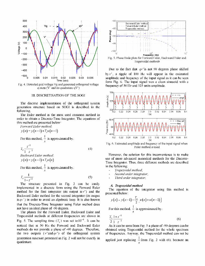
400 Due to the fact that qv' is not 90 degrees phase shifted
-50C ~~~~~~~~~~~byv',a ripple of 100 Hz will appear in the estimated-500 0.005 0.01 0.015 0.02 0.025 0.03 0.035 amplitude and frequency of the input signal as it can be seenTime (sec) form Fig. 6. The input signal was a clean sinusoid with a
Fig. 4. Distorted grid voltage Vg and generated orthogonal voltage frequency of 50 Hz and 325 units amplitude.system (V' and its quadrature qV')
330111. DISCRETISATION OF THE SOGI 3L
.Z 325The discrete implementation of the orthogonal system 0 A
Egeneration structure based on SOGI is described in the <
320 -following. 0.2 0.22 0.24 0.26 0.28 0.3 0.32 0.34 0.36 0.38 0.4
The Euler method is the most used common method in t [s]order to obtain a Discrete-Time Integrator. The equations of 50.5 - r ref.......!.!this method are presented below: freqForward Euler method: 50 *jy(n) =y(n-1)+fTu(n-i1) W
.5 -.
F t m1
0.2 0.22 0.24 0.26 0.28 0.3 0.32 0.34 0.36 0.38 0.4For this method, - iS approximated bRy:t[sIs t [s]-1 Fig. 6. Estimated amplitude and frequency of the input signal when
TS Z (4) Euler method is used1-z
Backward Euler method: However, the solution for this inconvenience is to makey(n) = y(n-1) u(n) use of more advanced numerical methods for the Discrete-
Time Integrator. Thus, three different methods are describedFor this method, - is approximated by: in the following:
s - Trapezoidal method;- Second order integrator;
1 (5) Third order integrator;The structure presented in Fig. 2 can be easily A. Trapezoidal method
implemented in a discrete form using the Forward Euler The equation of the integrator using this method ismethod for the first integrator (its output isv') and the presentedbelowBackward Euler method for the second integrator (its output Tisqv') in order to avoid an algebraic loop. It is also known y(n) = y(n-l)+ s [u(n)+u(n-l)]that the Discrete-Time Integrator using Euler method does 1not have an ideal phase of -90 degrees. For this method, - is approximated by:
The phases for the Forward Euler, Backward Euler and sTrapezoidal methods at different frequencies are shown in Ts I + z-1Fig. 5. The sampling time (Ts) was set to 1-4. It can be 2 I-z-1 (6)noticed that at 50 Hz the Forward and Backward Euler As it can be seen from Fig. 5 a phase of-90 degrees can bemethods do not provide a phase of -90 degrees. Therefore, obtained using Trapezoidal method for the whole spectrumthe two outputs (v' and qv') of the orthogonal system of frequencies. Anyway, the Trapezoidal method can not begeneration structure presented in Fig. 2 will not be exactly in . .. 1, ~~~~~~~~~~~~~appliedJUSt replacing - from Fig. 2 with (6), because anquadrature. s

algebraic loop will issue. Therefore, the solution is to use the B. Second order integratorTrapezoidal method for the close-loop transfer function The equation of the second order integrator is presented(Hd V) presented in (2) in order to avoid any other below [12]:algebraic loops. y(n) = y(n-l)+ s [3u(n-1)-u(n-2)]
Replacings by 2 z-1 in 1iczy+ ,in (2) will result: For this method, - is approximated by:
k 2 z-1 TS 3z - -2
kT- z12 IZ1 (12)Ho(z) - Tz+l (7) 2 1-z
(2z-1W2z~2-1 The implementation of the second order using (12)C7T +1,J+kcy 1 + co integrator is presented in Fig. 8.
Solving further the equation it results: Out(2kcoTs)(-)z
2 _I
Ho(z) = 4 (z + (2k)T)(z2 -1) (z )In
Fx = 2koTsTMaking the following substitutions 2 and
bringing the equation to a canonical form it will result: 2Fig. 8. Second order integrator implementation
x+ + -x +z-2 C. Third order integrator
Ho (z)_ _x+y+4_ _x+y+4 (9) The equation of the third order integrator is given in theI 2(4-y) 1 (x-Y-4 2 ( following [12]:
tx+y+4) x+y+4) y(n)=y(n-1)+ T-s 23u (n-1)- 16u(n-2)+5u(n-3)b x 2(4 - y)
t x + i + 4 n x + y +4 For this method, - is approximated by:Substituting b - and x-y-4's
{ x+y+4 0 2 x+y+4 23z- -16z7 +5z (13)y ~~~~~~~121-f'1
a simple discrete form of (2) is obtained: Fig. 9 shows the implementation of the third order integrator.bo +b2z-2Hd (Z)1 -2(10) +
-alz-l -a2z-2 ut
Furthermore, (9) can be represented as follows:
Hd(Z)=bo. 1 - ( 1)-1_ -2 /6 5
1alz -a2zThe implementation of the Trapezoidal method using (11)
is depicted in Fig. 7, where w 2TI co.
v 12Fig. 9. Third order integrator implementation
w qv+ + _ In Fig. 10, a comparison between the Trapezoidal Method
v (T), second order integrator (2) and third order integrator (3)is made. As it can be noticed, the best results are obtained
bo a, x a2 x when the third order integrator is used. Anyway, the all three+ proposed solutions give very good results compared to thec> ~~~~~~Eulermethod.
Fig. 7. Trapezoidal method implementation

500
Fig.325.4- Estimated -tampl T 400 Amp- -i. e [s]Vg...ampl3 30
E 325.2-
<S --ond order inertr Thir orde -Ieraoand Trapezoidal......
I I ~~~ II I I I ~~~~I I -~ 200325.1
0.2 0.22 0.24 0.26 0.28 0.3 0.32 0.34 0.36 0.38 0.4 (D 10t [s]
_____________________________~~~~~~~~~~0 ---50.01- are u -100 1
-freqTg w r w t strucureeres-200
freq 3
U- 49.99- qVa-V
0.2 0.22 0.24 0.26 0.28 0.3 0.32 0.34 0.36 0.38 0.4[s] -5OC
Fig. 10. Estimated amplitude and frequency of the input signal when Time.0 00 00 [s].20.401 01
Second order integrator, Third order integrator and Trapezoidal Fi.13irimolae eaof50s Nths k08method are usedFi.1.Givotgsaof5%-Nchsk-08IV. EXPERIMENTAL RESULTS ~All the experimental results were obtained using the PLLIV. EXPERIMENTAL RESULTS structure presented in Fig. 1. The block "Orthogonal system
An experimental system using a grid simulator (5kVA generation" was replaced with the structure presented in Fig.AC Power Source - model 5001 ix - Califoria Instruments) 2. For all experimental results presented in this paper, the PIhas been builtin order to test the proposed structure. The controller parameters of the PLL structure were set as
hastrol structure been b sing A I 03 follows: - the settling time Tset=0.06 s; - dumping factor 41.conto sii All the measurements have been done without usingplatform.adiinlftes
The proposed PLL structure based on second order additional filters.generalized integrator is experimentally validated in the Fig. 11, 12 and 13 show the behaviour of the PLL systemfollowing. based on SOGI under grid voltage sag of 500O. The effect of
400 the gain k (Fig. 2) at two different values is depicted in Fig.11 and 12 for a grid voltage THD of 10%. It can be noticed
300 .. b that a smaller value of the gain gives a better filtering but
200 AmpI. ~~~~~~~~~slowsthe dynamic of the system. In Fig. 13 the proposedThPLL structure is tested under a high content of notches in the
-300- ---V ----- WV- ---v --- --9-1 grid voltage.Fig. 14 and 15 show a frequency step and sweep response
0 .0 .0 .0 .0 01 .1 .1 .1.102 (T e-.0.)
> ~~~~~~~~~~~~~~from50Oup to 51 Hz. It can be observed a fast estimation of-100 the grid frequency. The grid voltage THD was set to 300 for
this experiment.qva ~~~~~~~~ThePLL behaviour under a phase jump of 60 degrees and
-300 -V .......... ...voltage sag of 2500 is presented in Fig. 16. It can be noticedVg ~~~~~~~~~~~thatthe PLL system repnsaccording toissettling tm
-400 r t i time0 0.02 0.04 0.06 0.08 0.1 0.12 0.14 0.16 0.18 0.2 (Tset=0.06 s).
Time [s]Fig. 11. Grid voltage sag of 50% - IO% THD (k=0.48) 51.
4CC~~~~~~~~~~~~~~~~~~~~~5.300 Ampl. 5
N
200 5.U-,
250.
-200 49.8.... .... ..freq. ref.'\ qV 49. --- -- est.freq.
VI. REFERENCES51.6
51.4 [1] L.N. Arruda, S.M. Silva, B.J.C. Filho, "PLL structures51.2 for utility connected systems", Industry Applications
51 . . 11Conference IAS, 2001, vol.4, pp. 2655 - 2660.>w 50.8 [2] N. Saitou, M. Matsui, and T. Shimizu, "A Control
50.6 Strategy of Single-phase Active Filter using a Novel d-q2 50.4 Transformation", Industry Applications Society IAS,U_ 50.4 S .2003, pp. 1222-1227.
50.2 [3] S.M. Silva, B.M. Lopes, B.J.C. Filho, R.P. Campana,50 ------------------- "Performance evaluation of PLL algorithms for single-
49.8 :req-ref phase grid-connected systems", Industry Applications49.6 est freq Conference, 2004, vol.4, pp. 2259 - 2263.
[4] S.M. Silva, L.N. Arruda, and B.J.C. Filho, , "WideTime [s] Bandwidth Single and Three-Phase PLL Structures for
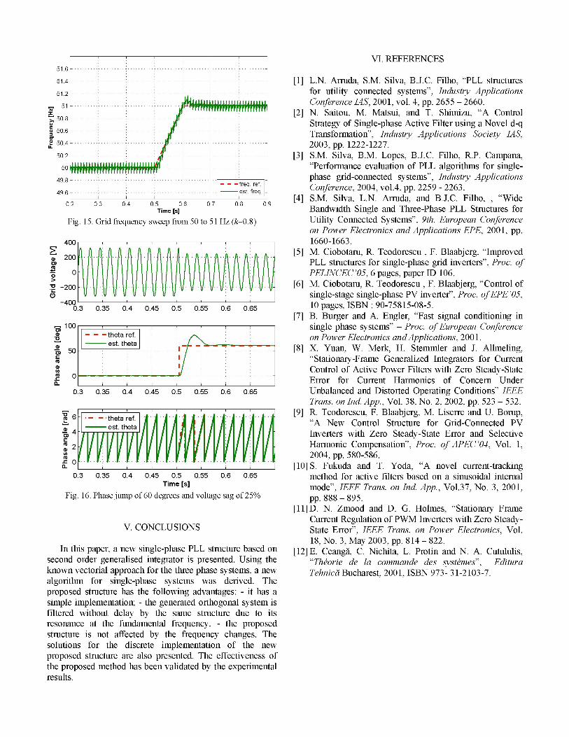
Fig. 15. Grid frequency sweep from 50 to 51 Hz (k-0.8) Utility Connected Systems", 9th. European Conferenceon Power Electronics and Applications EPE, 2001, pp.
400 1660-1663.2: ~ ~~~- ----[5] M. Ciobotaru, R. Teodorescu , F. Blaabjerg, "ImprovedE200009i j4z>PLL structures for single-phase grid inverters", Proc. of
0 ~~~~~~~~~~~~~~PELINCEC'05, 6 pages, paper ID 106.C -200 ~~~~~~~~~~~~[6]M. Ciobotaru, R. Teodorescu, F. Blaabjerg, "Control of
______single-stage single-phase PV inverter", Proc. ofEPE '05,-400C 10 pages, ISBN: 90-75815-08-5.0.3 0.35 0.4 0.45 0.5 0.55 0.6 0.65
[7] B. Burger and A. Engler, "Fast signal conditioning int 100 r single phase systems" - Proc. of European Conference
° ___ 1 C oon Power Electronics and Applications, 2001.50 7 --------------[8] X. Yuan, W. Merk, H. Stemmler and J. Allmeling,
"Stationary-Frame Generalized Integrators for CurrentO / Control of Active Power Filters with Zero Steady-Statea. Error for Current Harmonics of Concern Under
0.3 0.35 0.4 0.45 0.5 0.55 0.6 0.65 Unbalanced and Distorted Operating Conditions" IEEETrans. on Ind. App., Vol. 38, No. 2, 2002, pp. 523 - 532.
X 6 -~ -~ theta ref. [9] R. Teodorescu, F. Blaabjerg, M. Liserre and U. Borup,
6. theta re.4 .5 05 05 . .5mto o cieflesbsdo iuodlitra
[llD"A New Control Structure for Grid-Connected PVest. thetaB Inverters with Zero Steady-State Error and Selective
2 ErHarmonic Compensation", Proc. of APECt'04, Vol. 1,12004, pp. 580-586.
a.ipp,nesgeheP srcrbs o [IO] S. Fukuda and T. Yoda, "A novel current-tracking0.3 0.35 0.4 0.45 0.5 0.55 0.6 0.65 method for active filters based on a sinusoidal intemral
Time[st mode", IEEE Trans. on Ind App., Vol.37, No. 3, 2001,Fig. 16. Phase jump of 60 degrees and voltage sag ofw25 pp.888 - 895.
[11]sD. N. Zmood and D. G. Holmes, "Stationary Frame
V.sCONCLUSIONSeCurrent Regulation of PWM Inverters with Zero Steady-V. CONCLUSIONS ~~~~State Error", IEEE Trans. on Power Electronics, Vol.
Ine withisoutper, a new single-phase PLL structurebasedon18, No. 3, May 2003, pp. 814 822.
Iecondtiper aenewasi se PL sre bsedgon [12] B. Ceangd, C. Nichita, L. Protin and N. A. Cutululis,senown order genrais i or is presented. ne "Theorie de la commande des systtmes", Edituraknow vecorilaproac fo thethre phse sstes, anewTehnicL!i Bucharest, 2001, ISBN 973- 31-2103-7.algorithm for single-phase systems was derived. Theproposed structure has the following advantages: - it has asimple implementation; - the generated orthogonal system isfiltered without delay by the same structure due to its
the proposed method has been validated by the experimentalresults.