Matter-wave interferometry in a double well on an atom chip
6
arXiv:quant-ph/0507047v2 26 Sep 2005 Matter-wave interferometry in a double well on an atom chip T. Schumm, 1, 2 S. Hofferberth, 1 L. M. Andersson, 1 S. Wildermuth, 1 S. Groth, 1, 3 I. Bar-Joseph, 3 J. Schmiedmayer, 1, ∗ and P. Kr¨ uger 1,4, † 1 Physikalisches Institut, Universit¨at Heidelberg, D-69120 Heidelberg, Germany 2 Laboratoire Charles Fabry de l’Insitut d’Optique, UMR 8105 du CNRS, F-91403 Orsay, France 3 Department of Condensed Matter Physics, The Weizmann Institute of Science, Rehovot 76100, Israel 4 Current address: Laboratoire Kastler Brossel, ´ Ecole Normale Sup´ erieure, F-75005 Paris, France (Dated: February 1, 2008) Matter-wave interference experiments enable us to study matter at its most basic, quantum level and form the basis of high-precision sensors for applications such as inertial and gravitational field sensing. Success in both of these pursuits requires the development of atom-optical elements that can manipulate matter waves at the same time as preserving their coherence and phase. Here, we present an integrated interferometer based on a simple, coherent matter-wave beam splitter constructed on an atom chip. Through the use of radio-frequency-induced adiabatic double-well potentials, we demonstrate the splitting of Bose-Einstein condensates into two clouds separated by distances ranging from 3 to 80 μm, enabling access to both tunnelling and isolated regimes. Moreover, by analysing the interference patterns formed by combining two clouds of ultracold atoms originating from a single condensate, we measure the deterministic phase evolution throughout the splitting process. We show that we can control the relative phase between the two fully separated samples and that our beam splitter is phase-preserving. PACS numbers: 39.90.+d, 03.75.Be The wave nature of matter becomes visible in inter- ference experiments [1]. Interferometry with atoms has become an important tool for both fundamental and ap- plied experiments in the diverse fields of atomic physics, quantum optics, and metrology [2]. For example, highly accurate acceleration measurements have been based on atom interference [3]. Even though in most cases, inter- ference is fundamentally a single particle phenomenon, the experiments become even more powerful when per- formed with Bose-Einstein condensates (BECs). Inter- ferometry was used to demonstrate the remarkable prop- erty of atoms in a BEC to possess a common phase [4]. Realizing miniaturized matter-wave interferometers, as well as controlling and engineering quantum states on a microscale in general, have been long standing goals. Mi- croscopic integrated matter-wave devices [5] can be used to study the physics of correlated many-body quantum systems and are promising candidates for the implemen- tation of scalable quantum information processing [6]. The combination of well-established tools for atom cooling and manipulation with state-of-the-art microfab- rication technology has led to the development of atom chips [5, 7, 8, 9, 10]. These devices have been shown to be capable of trapping and guiding ultracold atoms on a microscale. A variety of complex manipulation poten- tials have been formed using magnetic [11], electric [12], and optical fields [13]. BECs can be created efficiently in such microtraps and coherent quantum phenomena such as internal-state Rabi oscillations [14] and coherent split- ting in momentum space [15, 16] have been observed. It is of particular interest to control the external (mo- tional) degrees of freedom of trapped atoms and spatially delocalized wave packets on a quantum level [17, 18]. A generic configuration for studies of matter-wave dynam- ics is the double well [19, 20]. Dynamically splitting a single trap into a double well is analogous to a beam splitter in optics and hence forms a basic element of a matter-wave interferometer. Interferometers on a mi- crochip can be used as highly sensitive devices because they allow measurements of quantum phases. This en- ables experiments exploring the intrinsic phase dynam- ics in complex interacting quantum systems (for exam- ple, Josephson oscillations [20, 21]) or the influence of the coupling to an external ’environment’ (decoherence [22]). Technologically, chip-based atom interferometers promise to be very useful as inertial sensors on a mi- croscale [23]. For all these applications it is imperative that the deterministic coherent quantum evolution of the matter waves is not perturbed by the splitting process itself. Although several atom chip beam-splitter config- urations have been proposed and experimentally demon- strated [12, 24, 25, 26, 27] none of them has fulfilled this crucial requirement. We present an easily implementable scheme for a phase preserving matter-wave beam splitter. We demonstrate experimentally, for the first time, coherent spatial split- ting and subsequent stable interference of matter waves on an atom chip. Our scheme is exclusively based on a combination of static and radio-frequency (RF) magnetic fields forming an adiabatic potential [28]. The atomic system in the combined magnetic fields can be described by a hamiltonian with uncoupled adiabatic eigenstates, so-called dressed states. For sufficiently strong ampli- tudes of the RF field, transitions between the adiabatic levels are inhibited as the strong coupling induces large repulsion of these levels. This property of the combined
Transcript of Matter-wave interferometry in a double well on an atom chip

arX
iv:q
uant
-ph/
0507
047v
2 2
6 Se
p 20
05
Matter-wave interferometry in a double well on an atom chip
T. Schumm,1, 2 S. Hofferberth,1 L. M. Andersson,1 S. Wildermuth,1
S. Groth,1, 3 I. Bar-Joseph,3 J. Schmiedmayer,1, ∗ and P. Kruger1, 4, †
1Physikalisches Institut, Universitat Heidelberg, D-69120 Heidelberg, Germany2Laboratoire Charles Fabry de l’Insitut d’Optique, UMR 8105 du CNRS, F-91403 Orsay, France
3Department of Condensed Matter Physics, The Weizmann Institute of Science, Rehovot 76100, Israel4Current address: Laboratoire Kastler Brossel, Ecole Normale Superieure, F-75005 Paris, France
(Dated: February 1, 2008)
Matter-wave interference experiments enable us to study matter at its most basic, quantum leveland form the basis of high-precision sensors for applications such as inertial and gravitational fieldsensing. Success in both of these pursuits requires the development of atom-optical elements thatcan manipulate matter waves at the same time as preserving their coherence and phase. Here,we present an integrated interferometer based on a simple, coherent matter-wave beam splitterconstructed on an atom chip. Through the use of radio-frequency-induced adiabatic double-wellpotentials, we demonstrate the splitting of Bose-Einstein condensates into two clouds separatedby distances ranging from 3 to 80 µm, enabling access to both tunnelling and isolated regimes.Moreover, by analysing the interference patterns formed by combining two clouds of ultracold atomsoriginating from a single condensate, we measure the deterministic phase evolution throughout thesplitting process. We show that we can control the relative phase between the two fully separatedsamples and that our beam splitter is phase-preserving.
PACS numbers: 39.90.+d, 03.75.Be
The wave nature of matter becomes visible in inter-ference experiments [1]. Interferometry with atoms hasbecome an important tool for both fundamental and ap-plied experiments in the diverse fields of atomic physics,quantum optics, and metrology [2]. For example, highlyaccurate acceleration measurements have been based onatom interference [3]. Even though in most cases, inter-ference is fundamentally a single particle phenomenon,the experiments become even more powerful when per-formed with Bose-Einstein condensates (BECs). Inter-ferometry was used to demonstrate the remarkable prop-erty of atoms in a BEC to possess a common phase [4].Realizing miniaturized matter-wave interferometers, aswell as controlling and engineering quantum states on amicroscale in general, have been long standing goals. Mi-croscopic integrated matter-wave devices [5] can be usedto study the physics of correlated many-body quantumsystems and are promising candidates for the implemen-tation of scalable quantum information processing [6].
The combination of well-established tools for atomcooling and manipulation with state-of-the-art microfab-rication technology has led to the development of atomchips [5, 7, 8, 9, 10]. These devices have been shown tobe capable of trapping and guiding ultracold atoms ona microscale. A variety of complex manipulation poten-tials have been formed using magnetic [11], electric [12],and optical fields [13]. BECs can be created efficiently insuch microtraps and coherent quantum phenomena suchas internal-state Rabi oscillations [14] and coherent split-ting in momentum space [15, 16] have been observed.
It is of particular interest to control the external (mo-tional) degrees of freedom of trapped atoms and spatiallydelocalized wave packets on a quantum level [17, 18]. A
generic configuration for studies of matter-wave dynam-ics is the double well [19, 20]. Dynamically splitting asingle trap into a double well is analogous to a beamsplitter in optics and hence forms a basic element of amatter-wave interferometer. Interferometers on a mi-crochip can be used as highly sensitive devices becausethey allow measurements of quantum phases. This en-ables experiments exploring the intrinsic phase dynam-ics in complex interacting quantum systems (for exam-ple, Josephson oscillations [20, 21]) or the influence ofthe coupling to an external ’environment’ (decoherence[22]). Technologically, chip-based atom interferometerspromise to be very useful as inertial sensors on a mi-croscale [23]. For all these applications it is imperativethat the deterministic coherent quantum evolution of thematter waves is not perturbed by the splitting processitself. Although several atom chip beam-splitter config-urations have been proposed and experimentally demon-strated [12, 24, 25, 26, 27] none of them has fulfilled thiscrucial requirement.
We present an easily implementable scheme for a phasepreserving matter-wave beam splitter. We demonstrateexperimentally, for the first time, coherent spatial split-ting and subsequent stable interference of matter waveson an atom chip. Our scheme is exclusively based on acombination of static and radio-frequency (RF) magneticfields forming an adiabatic potential [28]. The atomicsystem in the combined magnetic fields can be describedby a hamiltonian with uncoupled adiabatic eigenstates,so-called dressed states. For sufficiently strong ampli-tudes of the RF field, transitions between the adiabaticlevels are inhibited as the strong coupling induces largerepulsion of these levels. This property of the combined
2
static and RF fields could be exploited to form trap-ping geometries using the effective potential acting onthe dressed eigenstates [29], and related demonstrationexperiments with thermal atoms have been performed[30].
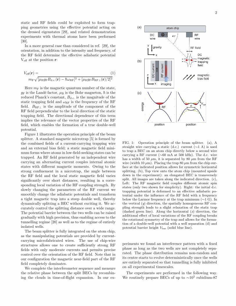
In a more general case than considered in ref. [29], theorientation, in addition to the intensity and frequency, ofthe RF field determine the effective adiabatic potentialVeff at the position r:
Veff(r) = (1)
mF
√
[µBgFBd.c.(r) − hωRF]2 + [µBgFBRF⊥(r)/2]2
Here mF is the magnetic quantum number of the state,gF is the Lande factor, µB is the Bohr magneton, h is thereduced Planck’s constant, Bd.c.
is the magnitude of thestatic trapping field and ωRF is the frequency of the RFfield. BRF⊥ is the amplitude of the component of theRF field perpendicular to the local direction of the statictrapping field. The directional dependence of this termimplies the relevance of the vector properties of the RFfield, which enables the formation of a true double-wellpotential.
Figure 1 illustrates the operation principle of the beamsplitter. A standard magnetic microtrap [5] is formed bythe combined fields of a current-carrying trapping wireand an external bias field; a static magnetic field mini-mum forms where atoms in low-field-seeking states can betrapped. An RF field generated by an independent wirecarrying an alternating current couples internal atomicstates with different magnetic moments. Owing to thestrong confinement in a microtrap, the angle betweenthe RF field and the local static magnetic field variessignificantly over short distances, resulting in a corre-sponding local variation of the RF coupling strength. Byslowly changing the parameters of the RF current wesmoothly change the adiabatic potentials and transforma tight magnetic trap into a steep double well, therebydynamically splitting a BEC without exciting it. We ac-curately control the splitting distance over a wide range.The potential barrier between the two wells can be raisedgradually with high precision, thus enabling access to thetunnelling regime [20] as well as to the regime of entirelyisolated wells.
The beam splitter is fully integrated on the atom chip,as the manipulating potentials are provided by current-carrying microfabricated wires. The use of chip-wirestructures allows one to create sufficiently strong RFfields with only moderate currents and permits precisecontrol over the orientation of the RF field. Note that inour configuration the magnetic near-field part of the RFfield completely dominates.
We complete the interferometer sequence and measurethe relative phase between the split BECs by recombin-ing the clouds in time-of-flight expansion. In our ex-
FIG. 1: Operation principle of the beam splitter. (a), Astraight wire carrying a static (d.c.) current (∼1 A) is usedto trap a BEC on an atom chip directly below a second wirecarrying a RF current (∼60 mA at 500 kHz). The d.c. wirehas a width of 50 µm, it is separated by 80 µm from the RFwire (width 10 µm). Placing the trap 80 µm from the chip sur-face at the indicated position allows for symmetric horizontalsplitting. (b), Top view onto the atom chip (mounted upsidedown in the experiment): an elongated BEC is transverselysplit. All images are taken along the indicated direction. (c),Left: The RF magnetic field couples different atomic spinstates (only two shown for simplicity). Right: the initial d.c.trapping potential is deformed to an effective adiabatic po-tential under the influence of the RF field with a frequencybelow the Larmor frequency at the trap minimum (∼1 G). Inthe vertical (y) direction, the spatially homogeneous RF cou-pling strength leads to a slight relaxation of the static trap(dashed green line). Along the horizontal (x) direction, theadditional effect of local variations of the RF coupling breaksthe rotational symmetry of the trap and allows for the forma-tion of a double-well potential with a well separation (d) andpotential barrier height Vbar (solid blue line).
periments we found an interference pattern with a fixedphase as long as the two wells are not completely sepa-rated. The phase distribution remains non-random andits centre starts to evolve deterministically once the wellsare entirely separated so that tunnelling is fully inhibitedon all experimental timescales.
The experiments are performed in the following way.We routinely prepare BECs of up to ∼105 rubidium-87
3
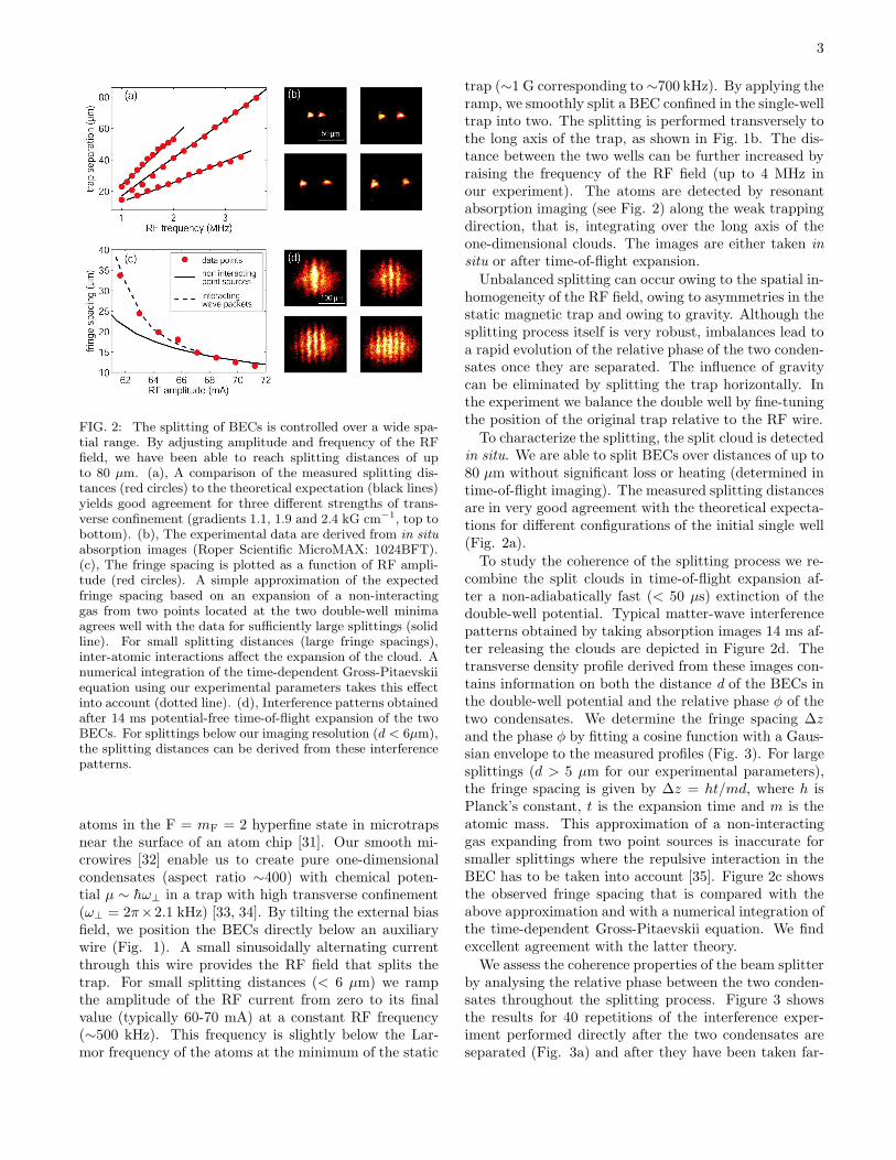
FIG. 2: The splitting of BECs is controlled over a wide spa-tial range. By adjusting amplitude and frequency of the RFfield, we have been able to reach splitting distances of upto 80 µm. (a), A comparison of the measured splitting dis-tances (red circles) to the theoretical expectation (black lines)yields good agreement for three different strengths of trans-verse confinement (gradients 1.1, 1.9 and 2.4 kG cm−1, top tobottom). (b), The experimental data are derived from in situ
absorption images (Roper Scientific MicroMAX: 1024BFT).(c), The fringe spacing is plotted as a function of RF ampli-tude (red circles). A simple approximation of the expectedfringe spacing based on an expansion of a non-interactinggas from two points located at the two double-well minimaagrees well with the data for sufficiently large splittings (solidline). For small splitting distances (large fringe spacings),inter-atomic interactions affect the expansion of the cloud. Anumerical integration of the time-dependent Gross-Pitaevskiiequation using our experimental parameters takes this effectinto account (dotted line). (d), Interference patterns obtainedafter 14 ms potential-free time-of-flight expansion of the twoBECs. For splittings below our imaging resolution (d < 6µm),the splitting distances can be derived from these interferencepatterns.
atoms in the F = mF = 2 hyperfine state in microtrapsnear the surface of an atom chip [31]. Our smooth mi-crowires [32] enable us to create pure one-dimensionalcondensates (aspect ratio ∼400) with chemical poten-tial µ ∼ hω⊥ in a trap with high transverse confinement(ω⊥ = 2π×2.1 kHz) [33, 34]. By tilting the external biasfield, we position the BECs directly below an auxiliarywire (Fig. 1). A small sinusoidally alternating currentthrough this wire provides the RF field that splits thetrap. For small splitting distances (< 6 µm) we rampthe amplitude of the RF current from zero to its finalvalue (typically 60-70 mA) at a constant RF frequency(∼500 kHz). This frequency is slightly below the Lar-mor frequency of the atoms at the minimum of the static
trap (∼1 G corresponding to ∼700 kHz). By applying theramp, we smoothly split a BEC confined in the single-welltrap into two. The splitting is performed transversely tothe long axis of the trap, as shown in Fig. 1b. The dis-tance between the two wells can be further increased byraising the frequency of the RF field (up to 4 MHz inour experiment). The atoms are detected by resonantabsorption imaging (see Fig. 2) along the weak trappingdirection, that is, integrating over the long axis of theone-dimensional clouds. The images are either taken in
situ or after time-of-flight expansion.
Unbalanced splitting can occur owing to the spatial in-homogeneity of the RF field, owing to asymmetries in thestatic magnetic trap and owing to gravity. Although thesplitting process itself is very robust, imbalances lead toa rapid evolution of the relative phase of the two conden-sates once they are separated. The influence of gravitycan be eliminated by splitting the trap horizontally. Inthe experiment we balance the double well by fine-tuningthe position of the original trap relative to the RF wire.
To characterize the splitting, the split cloud is detectedin situ. We are able to split BECs over distances of up to80 µm without significant loss or heating (determined intime-of-flight imaging). The measured splitting distancesare in very good agreement with the theoretical expecta-tions for different configurations of the initial single well(Fig. 2a).
To study the coherence of the splitting process we re-combine the split clouds in time-of-flight expansion af-ter a non-adiabatically fast (< 50 µs) extinction of thedouble-well potential. Typical matter-wave interferencepatterns obtained by taking absorption images 14 ms af-ter releasing the clouds are depicted in Figure 2d. Thetransverse density profile derived from these images con-tains information on both the distance d of the BECs inthe double-well potential and the relative phase φ of thetwo condensates. We determine the fringe spacing ∆zand the phase φ by fitting a cosine function with a Gaus-sian envelope to the measured profiles (Fig. 3). For largesplittings (d > 5 µm for our experimental parameters),the fringe spacing is given by ∆z = ht/md, where h isPlanck’s constant, t is the expansion time and m is theatomic mass. This approximation of a non-interactinggas expanding from two point sources is inaccurate forsmaller splittings where the repulsive interaction in theBEC has to be taken into account [35]. Figure 2c showsthe observed fringe spacing that is compared with theabove approximation and with a numerical integration ofthe time-dependent Gross-Pitaevskii equation. We findexcellent agreement with the latter theory.
We assess the coherence properties of the beam splitterby analysing the relative phase between the two conden-sates throughout the splitting process. Figure 3 showsthe results for 40 repetitions of the interference exper-iment performed directly after the two condensates areseparated (Fig. 3a) and after they have been taken far-

4
FIG. 3: The coherence of the splitting is examined byanalysing matter-wave interference patterns. (a), Directly af-ter (0.1 ms) the BECs have been split far enough (d = 3.4 µm)to inhibit tunnelling completely. (b), After (0.8 ms) the cloudshave been taken farther apart (d = 3.85µm). Left: a cosinefunction with a Gaussian envelope is fitted to the profiles de-rived from the two-dimensional images (insets). This yieldsinformation on fringe spacing, contrast and phase. Right:contrast and relative phase for 40 realizations of the same ex-periment are plotted in a polar diagram (inset). A histogramof the same data shows a very narrow distribution of the dif-ferential phase (σ = 13◦) directly after separating the cloudsand a slightly broadened distribution (σ = 28◦) later in thesplitting process. Both phase spreads are significantly smallerthan what is expected for a random phase.
ther apart (Fig. 3b), respectively. We find a very narrowphase distribution with a Gaussian width of σ = 13◦ and28◦, respectively. Hence, the splitting process is phase-preserving and the beam splitter is coherent.
We have performed similar measurements throughoutthe entire splitting process, starting from a well separa-tion of d ∼ 3 µm where the BECs are still connectedto a splitting of d ∼ 5.5 µm. At larger d, the interfer-ence fringes are no longer optically resolved. For splittingdistances larger than 3.4 µm the potential barrier is suffi-ciently high to suppress tunnel coupling between the twowells, so that the splitting process is complete. For fastsplitting we find the phase distribution to be non-randomover the whole splitting range (Fig. 4a). In a more de-tailed experiment with slower splitting we find that thespread is smaller than the expectation of a randomizedphase by more than three standard deviations for split-ting times shorter than 2 ms (Fig. 4c). Within theselimits, our data show an increase in phase spread and a
FIG. 4: Evolution of the differential phase throughout thesplitting process. Error bars indicate the statistical error ofthe mean value. (a), Splitting the condensate to variable dis-tances within 12 ms (splitting speed 1.4 µm ms−1). Thedashed vertical line indicates the trap separation for whichthe chemical potential µ of the BEC equals the potential bar-rier height Vbar (3.4 µm). As long as the barrier betweenthe two wells is sufficiently low (left of the dashed line), therelative phase remains locked at zero. Once the wells arefully separated so that tunnelling is inhibited (right of thedashed line), the differential phase starts to evolve owing toa slight residual imbalance in the double well. (b), Relativephase of the two condensates throughout a slower splittingprocess (splitting speed 0.6 µm ms−1). The evolution of thedifferential phase is controlled by deliberately adjusting thedouble-well imbalance by displacing the trap. The observedevolution is in agreement with a numerical simulation basedon our experimental parameters (dashed lines) for all datasets (yellow, red, green and blue points). Both signs of imbal-ance have been realized and the phase evolution is observedfor a time (2 ms), which is more than four times the transverseoscillation period. (c), A typical distribution of the relativephase shows significantly non-random phases for the entiresplitting process, the limits for a deviation by one and threestandard deviations are indicated.
coinciding loss of average contrast. A possible explana-tion is the longitudinal phase diffusion inside the indi-vidual one-dimensional quasi-BECs [36]. This hypothe-sis is supported by the fact that we always observe phaserandomization (at finite interference contrast) approxi-mately 2.5 ms after the splitting is complete, indepen-dent of the splitting distance d. This timescale roughlyagrees with the theoretical prediction for our experimen-tal parameters. More detailed experimental studies ofthe longitudinal phase diffusion inside one-dimensionalquasi-BECs are underway.
5
As the splitting is a coherent operation, we are ableto measure the phase evolution throughout the splittingprocess. We find that the relative phase between thetwo condensates is locked to zero as long as the chemi-cal potential exceeds the potential barrier (d < 3.4 µm).Once the splitting is complete (d > 3.4 µm), a determin-istic phase evolution occurs (Fig. 4a,b). A differentialphase shift is induced by a slight residual imbalance ofthe double-well potential (in the case shown in Fig. 4aan energy difference of the order of h × 1 kHz µm−1 ad-ditional splitting).
The double-well imbalance can be controlled by ap-propriately adjusting the trap parameters. In our exper-iment we have studied this by varying the current in thed.c. trapping wire and thereby adjusting the position ofthe original single-well trap with respect to the RF wireand the orientation of the splitting axis with respect togravity. The data depicted in Fig. 4b show the result-ing phase evolution for four different settings. Again, thedifferential phase φ is zero as long as the clouds are notfully separated; once tunnelling is inhibited, φ evolvesquadratically with the split time. Although the differ-ential phase evolution in an asymmetric double well isusually linear in time, in our case the wells are separatedfurther as the split time is increased, so that the imbal-ance itself increases linearly with time. This leads to anoverall quadratic scaling, which is confirmed by a numer-ical integration of the time-dependent Gross-Pitaevskiiequation. We have varied both the sign and strength ofthe imbalance in the double-well potential. It is a crucialproperty of our beam splitter that the balancing is fairlyinsensitive to changes of the controlling parameter. Thebalancing can then be performed well above the experi-mental noise level. In the illustrated case we have variedthe d.c. wire current on the per cent level (∼10 mA cor-responding to a trap displacement of ∼ 1 µm), whereasthe current stability is better than 10−4. In our exper-iment, we have been able to balance the double well toan extent that within one transverse oscillation period(0.5 ms) after the condensates were fully separated, thephase shift remained smaller than 18◦.
There are several advantages of our atom chip beam-splitter concept over previously implemented approaches:the splitting distances are not limited by the structuresize on the chip [37], but rather by the ground-state sizeof the initial single-well trap that can be orders of mag-nitude smaller. This allows us to reach full splitting of aBEC of 1.1 µm transverse size (full width at half maxi-mum) at a double-well separation of only 3.4 µm. Thetrapping wire, in contrast, has a width of 50 µm; theatoms are located at a distance of 80 µm from the sur-face. Furthermore, the dynamic splitting process can beperformed in a smooth (adiabatic) fashion, avoiding ex-citations, by simply controlling the parameters of the RFfield.
In conclusion, we have demonstrated coherent splitting
and interference of BECs using an atom chip. Our ex-periments are based on a versatile microfabricated beamsplitter that is fully integrated on the chip. With our in-terferometer we have measured and controlled the phaseevolution between two BECs gradually split over increas-ingly large distances. We are convinced that such double-well potentials on atom chips are a starting point for avariety of in-depth studies of the dynamics of one- andthree-dimensional quantum gases. Exploring the split-ting and recombination process in more detail is an imme-diate next step, as are detailed studies of tunnelling andself-trapping in low-dimensional quantum gases [20, 38].Of particular interest will be the time-dependent evolu-tion and phase coherence along low-dimensional corre-lated quantum systems in the fully split and in the tun-nelling regimes. Applications of our scheme may rangefrom investigations of atom-surface interactions and thefundamental question of surface-induced decoherence tomicroscopic atom interferometers for precision metrology.Last but not least, simple and robust atom chip beamsplitters and interferometers based on our beam splittermay constitute the building blocks for quantum informa-tion processing on the atom chip [6, 17].
We thank H. Perrin and I. Lesanovsky for useful discus-sions. We acknowledge financial support from the Euro-pean Union, contract numbers IST-2001-38863 (ACQP),MRTN-CT-2003-505032 (Atom Chips), HPRN-CT-2002-00304 (FASTNet), HPMF-CT-2002-02022, and HPRI-CT-1999-00114 (LSF) and the Deutsche Forschungsge-meinschaft, contract number SCHM 1599/1-1.
∗ Electronic address: [email protected]† Electronic address: [email protected];
URL: http://www.atomchip.net[1] G. Badurek, H. Rauch, and A. Zeilinger, eds., Matter
Wave Interferometry (North Holland Physics PublishingDivision, Amsterdam, 1988).
[2] P. Berman, ed., Atom Interferometry, vol. 37 of Adv. At.
Mol. Opt. Phys. (Academic Press, New York, 1997).[3] M. Kasevich and S. Chu, Phys. Rev. Lett. 67, 181 (1991).[4] M. R. Andrews, C. G. Townsend, H.-J. Miesner, D. S.
Durfee, D. M. Kurn, and W. Ketterle, Science 275, 637(1997).
[5] R. Folman, P. Kruger, J. Schmiedmayer, J. Denschlag,and C. Henkel, Adv. At. Mol. Opt. Phys. 48, 263 (2002).
[6] M. A. Cirone, A. Negretti, T. Calarco, P. Krger,and J. Schmiedmayer (2005), published online DOI:10.1140/epjd/e2005-00175-8.
[7] D. Muller, D. Z. Anderson, R. J. Grow, P. D. D.Schwindt, and E. A. Cornell, Phys. Rev. Lett. 83, 5194(1999).
[8] J. Reichel, W. Hansel, and T. W. Hansch, Phys. Rev.Lett. 83, 3398 (1999).
[9] R. Folman, P. Kruger, D. Cassettari, B. Hessmo,T. Maier, and J. Schmiedmayer, Phys. Rev. Lett. 84,4749 (2000).
6
[10] N. H. Dekker, C. S. Lee, V. Lorent, J. H. Thywissen, S. P.Smith, M. Drndic, R. M. Westervelt, and M. Prentiss,Phys. Rev. Lett. 84, 1124 (2000).
[11] K. Brugger, P. Kruger, X. Luo, S. Wildermuth, H. Gim-pel, M. W. Klein, S. Groth, R. Folman, I. Bar-Joseph,and J. Schmiedmayer, Phys. Rev. A 72, 023607 (2005).
[12] P. Kruger, X. Luo, M. W. Klein, K. Brugger, A. Haase,S. Wildermuth, S. Groth, I. Bar-Joseph, R. Folman, andJ. Schmiedmayer, Phys. Rev. Lett. 91, 233201 (2003).
[13] R. Dumke, T. Muther, M. Volk, W. Ertmer, and G. Birkl,Phys. Rev. Lett. 89, 220402 (2002).
[14] P. Treutlein, P. Hommelhoff, T. Steinmetz, T. W.Hansch, and J. Reichel, Phys. Rev. Lett. 92, 203005(2004).
[15] Y.-J. Wang, D. Z. Anderson, V. M. Bright, E. A. Cornell,Q. Diot, T. Kishimoto, M. Prentiss, R. A. Saravanan,S. R. Segal, and S. Wu, Phys. Rev. Lett. 94 (2005).
[16] A. Gunther, S. Kraft, M. Kemmler, D. Koelle,R. Kleiner, C. Zimmermann, and J. Fortagh (2005),cond-mat/0504210.
[17] T. Calarco, E. A. Hinds, D. Jaksch, J. Schmiedmayer,J. I. Cirac, and P. Zoller, Phys. Rev. A 61, 022304 (2000).
[18] E. Charron, E. Tiesinga, F. Mies, and C. Williams, Phys.Rev. Lett. 88, 077901 (2002).
[19] Y. Shin, M. Saba, T. A. Pasquini, W. Ketterle, D. E.Pritchard, and A. E. Leanhardt, Phys. Rev. Lett. 92,050405 (2004).
[20] M. Albiez, R. Gati, J. Flling, S. Hunsmann, M. Cristiani,and M. K. Oberthaler1, Phys. Rev. Lett. 95, 010402(2005).
[21] B. D. Josephson, Physics Letters 1, 251 (1962).[22] W. H. Zurek, Rev. Mod. Phys. 75, 715 (2003).[23] M. Kasevich, Science 298, 1363 (2002).[24] D. Cassettari, B. Hessmo, R. Folman, T. Maier, and
J. Schmiedmayer, Phys. Rev. Lett. 85, 5483 (2000).[25] D. Muller, E. A. Cornell, M. Prevedelli, P. D. D.
Schwindt, A. Zozulya, and D. Z. Anderson, Opt. Lett.25, 1382 (2000).
[26] P. Hommelhoff, W. Hnsel, T. Steinmetz, T. W. Hnsch,and J. Reichel, New Journal of Physics 7, 3 (2005).
[27] Y. Shin, C. Sanner, G.-B. Jo, T. A. Pasquini, M. Saba,W. Ketterle, D. E. Pritchard, M. Vengalattore, andM. Prentiss (2005), cond-mat/0506464.
[28] E. Muskat, D. Dubbers, and O. Schrpf, Phys. Rev. Lett.58, 2047 (1987).
[29] O. Zobay and B. M. Garraway, Phys. Rev. Lett. 86, 1195(2001).
[30] Y. Colombe, E. Knyazchyan, O. Morizot, B. Mercier,V. Lorent, and H. Perrin, Europhys. Lett. 67, 593 (2004).
[31] S. Wildermuth, P. Kruger, C. Becker, M. Brajdic,S. Haupt, A. Kasper, R. Folman, and J. Schmiedmayer,Phys. Rev. A 69, 030901(R) (2004).
[32] S. Groth, P. Kruger, S. Wildermuth, R. Folman, T. Fern-holz, D. Mahalu, I. Bar-Joseph, and J. Schmiedmayer,Appl. Phys. Lett. 85, 2980 (2004).
[33] P. Kruger, L. M. Andersson, S. Wildermuth, S. Hoffer-berth, E. Haller, S. Aigner, S. Groth, I. Bar-Joseph, andJ. Schmiedmayer (2005), cond-mat/0504686.
[34] S. Wildermuth, S. Hofferberth, I. Lesanovsky, E. Haller,L. M. Andersson, S. Groth, I. Bar-Joseph, P. Kruger, andJ. Schmiedmayer, Nature 435, 440 (2005).
[35] A. Rohrl, M. Naraschewski, A. Schenzle, and H. Wallis,Phys. Rev. Lett. 78, 4143 (1997).
[36] N. K. Whitlock and I. Bouchoule, Phys. Rev. A 68,
053609 (2003).[37] J. Esteve, T. Schumm, J.-B. Trebbia, I. Bouchoule,
A. Aspect, and C. I. Westbrook, Eur. Phys. J. D 35,141 (2005).
[38] S. Giovanazzi, R. Shenoy, A. Smerzi, and S. Fantoni,Phys. Rev. Lett. 79, 4950 (1997).