A Review of Supercapacitors: Materials Design, Modification ...
Upload
khangminh22Category
view
1download
0
Materials
www.elsevier.com/locate/matdes
Materials and Design 27 (2006) 556–565
&Design
Quasi-static axial crushing of extruded polystyrene foam-filledthin-walled aluminum tubes: Experimental and numerical analysis
L. Aktay a, A.K. Toksoy b, M. Guden b,c,*
a Institute of Structures and Design, German Aerospace Center (DLR), Pfaffenwaldring 38–40, Stuttgart, Germanyb Department of Mechanical Engineering, Izmir Institute of Technology, Gulbahce Koyu, Urla, Izmir, Turkeyc Center for Materials Research, Izmir Institute of Technology, Gulbahce Koyu, Urla, 3540 Izmir, Turkey
Received 25 June 2004; accepted 6 December 2004Available online 2 March 2005
Abstract
The experimental and numerical quasi-static crushing responses of extruded closed cell polystyrene foam-filled thin-walled alu-minum tubes were investigated. The numerical crash analysis of empty and foam-filled tubes was performed using the explicit finiteelement code PAM-CRASHe. Satisfactory agreements were generally achieved between the finite element model and experimentaldeformed shapes, load–displacements, fold lengths and specific energy absorptions. The model and experiments have also high-lighted the several effects of foam filling on the crushing of thin-walled tubes. The energy absorptions in foam-filled tubes were fur-ther shown to be higher than the sum of the energy absorptions of empty tube (alone) and filler (alone).� 2005 Elsevier Ltd. All rights reserved.
Keywords: Foams (B); Foam-filled tubes; Finite element modeling
1. Introduction
It was first shown in 1960 by Alexander [1] that tubu-lar structures absorb the deformation energy nearly at aconstant load. This leads to very high energy absorptionefficiencies making these structures suitable for theapplications of impact load mitigation. Since Alexander,many experimental and numerical investigations havebeen conducted aiming at determining and understand-ing the crushing behavior of tubular structures and someof these have been recently reviewed by Alghamdi [2].The filling of tubular structures with lightweight foamsfor a goal of increasing specific energy absorption(SEA) has also taken considerable interest. One of theearliest investigations on the crushing behavior of thin-walled sections filled with lightweight polyurethane
0261-3069/$ - see front matter � 2005 Elsevier Ltd. All rights reserved.
doi:10.1016/j.matdes.2004.12.019
* Corresponding author. Tel.: +90 232 7506595; fax: +90 2327506505.
E-mail address: [email protected] (M. Guden).
foam was conducted by Thornton [3], who pointed outthat although noticeable increase in SEA was possiblewith foam filling, it was not weight effective when com-pared with the thickening of empty tube wall. Lampinenand Jeryan [4] investigated the crushing of sheet metaltubes filled with low density polyurethane foams andconcluded that foam filling stabilizes the deformationof thin-walled tubes. The crushing behavior of polyure-thane foam-filled thin-walled metal tubes was also inves-tigated by Reid et al. [5], at quasi-static and dynamicdeformation rates. It was concluded that tube wall inter-acts with the foam filler deformation resulting in a moretendency for the axisymmetric mode of deformation.They also concluded that the simple addition of the uni-axial foam contribution gave the total average crushingload of filled tube. Guillow et al. [6] have recentlypointed out that the average crushing loads of polyure-thane foam-filled aluminum (Al) thin-walled tubes weregreater than the sum of the average crushing loads ofempty tube (alone) and foam (alone), a result which
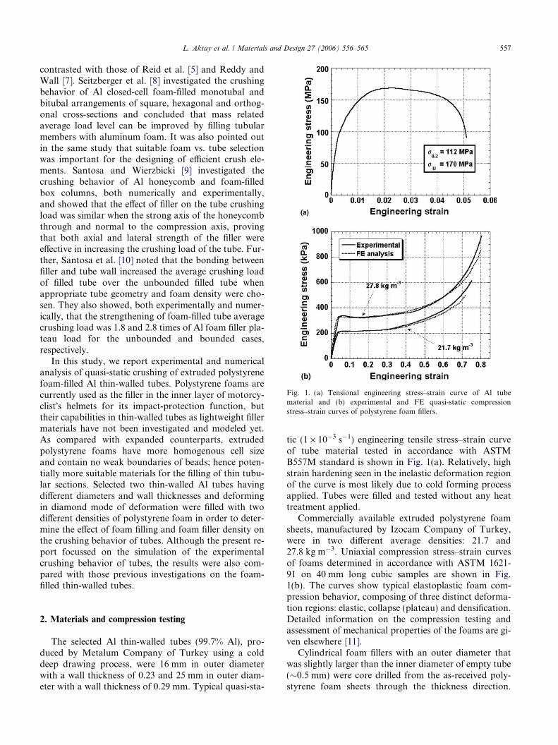
Fig. 1. (a) Tensional engineering stress–strain curve of Al tubematerial and (b) experimental and FE quasi-static compressionstress–strain curves of polystyrene foam fillers.
L. Aktay et al. / Materials and Design 27 (2006) 556–565 557
contrasted with those of Reid et al. [5] and Reddy andWall [7]. Seitzberger et al. [8] investigated the crushingbehavior of Al closed-cell foam-filled monotubal andbitubal arrangements of square, hexagonal and orthog-onal cross-sections and concluded that mass relatedaverage load level can be improved by filling tubularmembers with aluminum foam. It was also pointed outin the same study that suitable foam vs. tube selectionwas important for the designing of efficient crush ele-ments. Santosa and Wierzbicki [9] investigated thecrushing behavior of Al honeycomb and foam-filledbox columns, both numerically and experimentally,and showed that the effect of filler on the tube crushingload was similar when the strong axis of the honeycombthrough and normal to the compression axis, provingthat both axial and lateral strength of the filler wereeffective in increasing the crushing load of the tube. Fur-ther, Santosa et al. [10] noted that the bonding betweenfiller and tube wall increased the average crushing loadof filled tube over the unbounded filled tube whenappropriate tube geometry and foam density were cho-sen. They also showed, both experimentally and numer-ically, that the strengthening of foam-filled tube averagecrushing load was 1.8 and 2.8 times of Al foam filler pla-teau load for the unbounded and bounded cases,respectively.
In this study, we report experimental and numericalanalysis of quasi-static crushing of extruded polystyrenefoam-filled Al thin-walled tubes. Polystyrene foams arecurrently used as the filler in the inner layer of motorcy-clist�s helmets for its impact-protection function, buttheir capabilities in thin-walled tubes as lightweight fillermaterials have not been investigated and modeled yet.As compared with expanded counterparts, extrudedpolystyrene foams have more homogenous cell sizeand contain no weak boundaries of beads; hence poten-tially more suitable materials for the filling of thin tubu-lar sections. Selected two thin-walled Al tubes havingdifferent diameters and wall thicknesses and deformingin diamond mode of deformation were filled with twodifferent densities of polystyrene foam in order to deter-mine the effect of foam filling and foam filler density onthe crushing behavior of tubes. Although the present re-port focussed on the simulation of the experimentalcrushing behavior of tubes, the results were also com-pared with those previous investigations on the foam-filled thin-walled tubes.
2. Materials and compression testing
The selected Al thin-walled tubes (99.7% Al), pro-duced by Metalum Company of Turkey using a colddeep drawing process, were 16 mm in outer diameterwith a wall thickness of 0.23 and 25 mm in outer diam-eter with a wall thickness of 0.29 mm. Typical quasi-sta-
tic (1 · 10�3 s�1) engineering tensile stress–strain curveof tube material tested in accordance with ASTMB557M standard is shown in Fig. 1(a). Relatively, highstrain hardening seen in the inelastic deformation regionof the curve is most likely due to cold forming processapplied. Tubes were filled and tested without any heattreatment applied.
Commercially available extruded polystyrene foamsheets, manufactured by Izocam Company of Turkey,were in two different average densities: 21.7 and27.8 kg m�3. Uniaxial compression stress–strain curvesof foams determined in accordance with ASTM 1621-91 on 40 mm long cubic samples are shown in Fig.1(b). The curves show typical elastoplastic foam com-pression behavior, composing of three distinct deforma-tion regions: elastic, collapse (plateau) and densification.Detailed information on the compression testing andassessment of mechanical properties of the foams are gi-ven elsewhere [11].
Cylindrical foam fillers with an outer diameter thatwas slightly larger than the inner diameter of empty tube(�0.5 mm) were core drilled from the as-received poly-styrene foam sheets through the thickness direction.
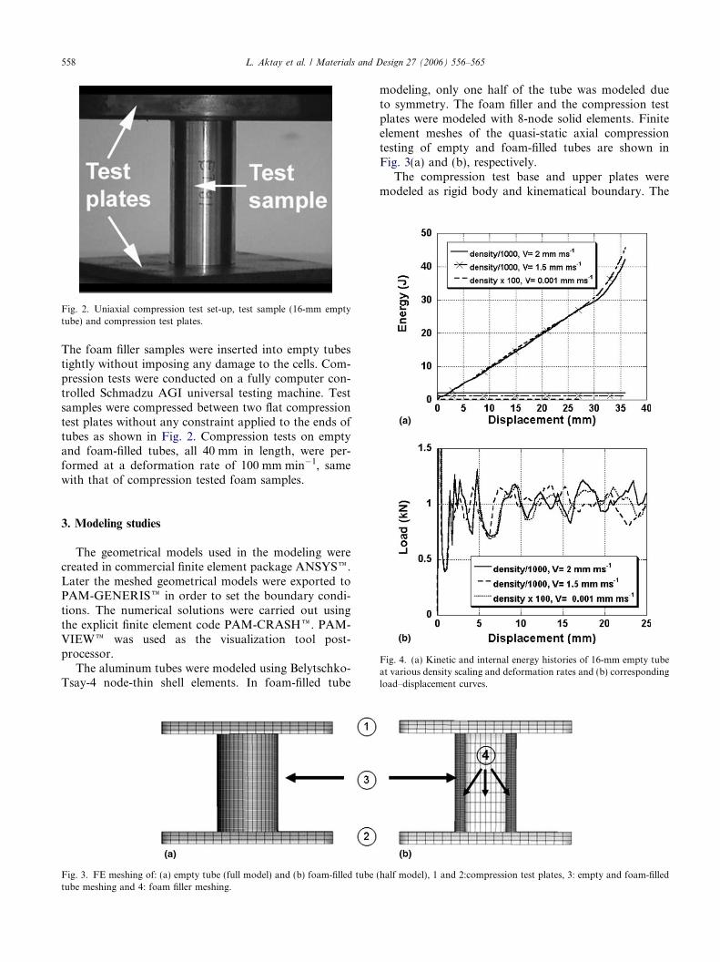
Fig. 2. Uniaxial compression test set-up, test sample (16-mm emptytube) and compression test plates.
558 L. Aktay et al. / Materials and Design 27 (2006) 556–565
The foam filler samples were inserted into empty tubestightly without imposing any damage to the cells. Com-pression tests were conducted on a fully computer con-trolled Schmadzu AGI universal testing machine. Testsamples were compressed between two flat compressiontest plates without any constraint applied to the ends oftubes as shown in Fig. 2. Compression tests on emptyand foam-filled tubes, all 40 mm in length, were per-formed at a deformation rate of 100 mm min�1, samewith that of compression tested foam samples.
Fig. 4. (a) Kinetic and internal energy histories of 16-mm empty tubeat various density scaling and deformation rates and (b) correspondingload–displacement curves.
3. Modeling studies
The geometrical models used in the modeling werecreated in commercial finite element package ANSYSe.Later the meshed geometrical models were exported toPAM-GENERISe in order to set the boundary condi-tions. The numerical solutions were carried out usingthe explicit finite element code PAM-CRASHe. PAM-VIEWe was used as the visualization tool post-processor.
The aluminum tubes were modeled using Belytschko-Tsay-4 node-thin shell elements. In foam-filled tube
Fig. 3. FE meshing of: (a) empty tube (full model) and (b) foam-filled tube (tube meshing and 4: foam filler meshing.
modeling, only one half of the tube was modeled dueto symmetry. The foam filler and the compression testplates were modeled with 8-node solid elements. Finiteelement meshes of the quasi-static axial compressiontesting of empty and foam-filled tubes are shown inFig. 3(a) and (b), respectively.
The compression test base and upper plates weremodeled as rigid body and kinematical boundary. The
half model), 1 and 2:compression test plates, 3: empty and foam-filled
L. Aktay et al. / Materials and Design 27 (2006) 556–565 559
displacements and rotations of the compression testplates were not allowed except the displacement of theupper plate along the vertical axis. The movement ofthe rigid body was fully determined by the movementof an artificial ‘‘node’’ located at the rigid body centerof gravity. Boundary conditions for the rigid body wereapplied to the center of gravity node only.
Material type 103 corresponding to the elastic–plasticisotropic thin shell material model was used for the tubematerial. Material type 103 uses an enhanced plasticityalgorithm that includes transverse shear effects. It ex-actly satisfies Hill�s criterion and precisely updates theelement thickness during the plastic deformation. Thebase and upper plates were modeled using an elastic–plastic solid element model called material type 1. Thismaterial model corresponds to elastic–plastic behaviorwith isotropic hardening and elastic–plastic behaviorcan be introduced by specifying the yield stress and tan-gent modulus or specifying the effective plastic strainsand stresses.
The material behavior of polystyrene foam was mod-eled using the crushable foam solid model, namely mate-
rial type 2. Material type 2 corresponds to the solidmaterials exhibiting coupled volumetric (bulk) and devi-atoric (shear) plasticity. The coupling between bothparts of the material response is established by a pres-
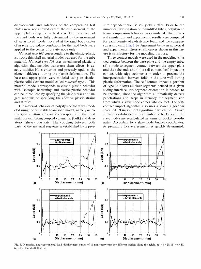
Fig. 5. Numerical and experimental load–displacement curves of 16-mm em(c) 40 · 80 and (d) 40 · 160.
sure dependent von Mises� yield surface. Prior to thenumerical investigation of foam-filled tubes, polystyrenefoam compression behavior was simulated. The numer-ical simulations and experimental results were comparedfor each density of polystyrene foam and the compari-son is shown in Fig. 1(b). Agreement between numericaland experimental stress–strain curves shown in this fig-ure is satisfactory for the modeling purpose.
Three contact models were used in the modeling: (i) atied contact between the base plate and the empty tube,(ii) a node-to-segment contact between the upper plateand the tube ends and (iii) a self-contact (self impactingcontact with edge treatment) in order to prevent theinterpenetration between folds in the tube wall duringplastic deformation. The self-contact impact algorithmof type 36 allows all slave segments defined in a givensliding interface. No segment orientation is needed tobe specified, since the algorithm automatically detectspenetrations and keeps in memory the segment sidefrom which a slave node comes into contact. The self-contact impact algorithm also uses a search algorithmso-called 3D Bucket sort algorithm in which the 3D slavesurface is subdivided into a number of buckets and theslave nodes are recalculated in terms of bucket coordi-nates. According to a slave node bucket coordinates,its proximity to slave segments is quickly determined.
pty tube for different meshes along the height: (a) 40 · 20, (b) 40 · 40,
560 L. Aktay et al. / Materials and Design 27 (2006) 556–565
After the global search phase, an accurate local searchalgorithm is started.
The folding of the tube wall results in local deforma-tion of and penetration to the foam filler surface. It was
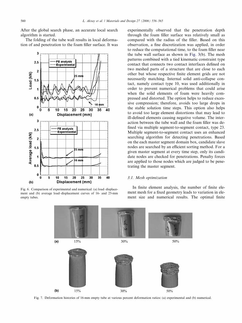
Fig. 6. Comparison of experimental and numerical: (a) load–displace-ment and (b) average load–displacement curves of 16- and 25-mmempty tubes.
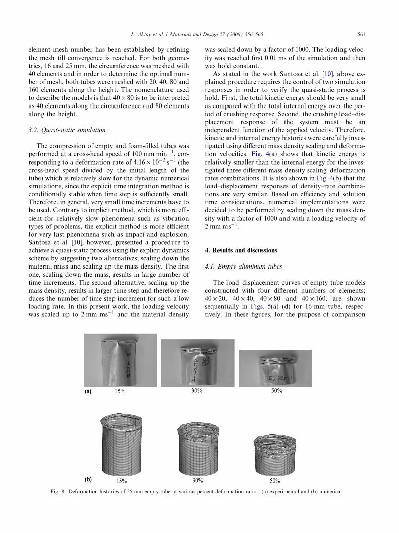
Fig. 7. Deformation histories of 16-mm empty tube at various per
experimentally observed that the penetration depththrough the foam filler surface was relatively small ascompared with the radius of the filler. Based on thisobservation, a fine discretization was applied, in orderto reduce the computational time, to the foam filler nearthe tube wall surface as shown in Fig. 3(b). The meshpatterns combined with a tied kinematic constraint typecontact that connects two contact interfaces defined ontwo meshed parts of a structure that are close to eachother but whose respective finite element grids are notnecessarily matching. Internal solid anti-collapse con-tact, namely contact type 10, was used additionally inorder to prevent numerical problems that could arisewhen the solid elements of foam were heavily com-pressed and distorted. The option helps to reduce exces-sive compression; therefore, avoids too large drops inthe stable solution time steps. This option also helpsto avoid too large element distortions that may lead toill-defined elements causing negative volume. The inter-action between the tube wall and the foam filler was de-fined via multiple segment-to-segment contact, type 23.Multiple segment-to-segment contact uses an enhancedsearching algorithm for detecting penetrations. Basedon the each master segment domain box, candidate slavenodes are searched by an efficient sorting method. For agiven master segment at every time step, only its candi-date nodes are checked for penetrations. Penalty forcesare applied to those nodes which are judged to be pene-trating the master segment.
3.1. Mesh optimization
In finite element analysis, the number of finite ele-ment mesh for a fixed geometry leads to variation in ele-ment size and numerical results. The optimal finite
cent deformation ratios: (a) experimental and (b) numerical.
L. Aktay et al. / Materials and Design 27 (2006) 556–565 561
element mesh number has been established by refiningthe mesh till convergence is reached. For both geome-tries, 16 and 25 mm, the circumference was meshed with40 elements and in order to determine the optimal num-ber of mesh, both tubes were meshed with 20, 40, 80 and160 elements along the height. The nomenclature usedto describe the models is that 40 · 80 is to be interpretedas 40 elements along the circumference and 80 elementsalong the height.
3.2. Quasi-static simulation
The compression of empty and foam-filled tubes wasperformed at a cross-head speed of 100 mm min�1, cor-responding to a deformation rate of 4.16 · 10�2 s�1 (thecross-head speed divided by the initial length of thetube) which is relatively slow for the dynamic numericalsimulations, since the explicit time integration method isconditionally stable when time step is sufficiently small.Therefore, in general, very small time increments have tobe used. Contrary to implicit method, which is more effi-cient for relatively slow phenomena such as vibrationtypes of problems, the explicit method is more efficientfor very fast phenomena such as impact and explosion.Santosa et al. [10], however, presented a procedure toachieve a quasi-static process using the explicit dynamicsscheme by suggesting two alternatives; scaling down thematerial mass and scaling up the mass density. The firstone, scaling down the mass, results in large number oftime increments. The second alternative, scaling up themass density, results in larger time step and therefore re-duces the number of time step increment for such a lowloading rate. In this present work, the loading velocitywas scaled up to 2 mm ms�1 and the material density
Fig. 8. Deformation histories of 25-mm empty tube at various per
was scaled down by a factor of 1000. The loading veloc-ity was reached first 0.01 ms of the simulation and thenwas hold constant.
As stated in the work Santosa et al. [10], above ex-plained procedure requires the control of two simulationresponses in order to verify the quasi-static process ishold. First, the total kinetic energy should be very smallas compared with the total internal energy over the per-iod of crushing response. Second, the crushing load–dis-placement response of the system must be anindependent function of the applied velocity. Therefore,kinetic and internal energy histories were carefully inves-tigated using different mass density scaling and deforma-tion velocities. Fig. 4(a) shows that kinetic energy isrelatively smaller than the internal energy for the inves-tigated three different mass density scaling–deformationrates combinations. It is also shown in Fig. 4(b) that theload–displacement responses of density–rate combina-tions are very similar. Based on efficiency and solutiontime considerations, numerical implementations weredecided to be performed by scaling down the mass den-sity with a factor of 1000 and with a loading velocity of2 mm ms�1.
4. Results and discussions
4.1. Empty aluminum tubes
The load–displacement curves of empty tube modelsconstructed with four different numbers of elements;40 · 20, 40 · 40, 40 · 80 and 40 · 160, are shownsequentially in Figs. 5(a)–(d) for 16-mm tube, respec-tively. In these figures, for the purpose of comparison
cent deformation ratios: (a) experimental and (b) numerical.

562 L. Aktay et al. / Materials and Design 27 (2006) 556–565
experimental load–displacement curve of 16-mm emptytube is also shown. As seen in Figs. 5(c) and (d), theload–displacement curves of models with 40 · 80 and40 · 160 elements give reasonably good agreements withthe experimental load–displacement curve, while theload–displacement curves of models constructed with40 · 20 and 40 · 40 elements show substantial disagree-ments. The similar effects of number of elements on theload–displacement curves of 25-mm empty tube werealso found. Finite element models were, however, con-tinued with 40 · 80 elements for both tube geometriesfor the computational efficiency.
It was experimentally and numerically found thatboth 16- and 25-mm empty tubes deformed in diamondmode and corresponding experimental and numericalload–displacement and average load–displacementcurves are shown in Figs. 6(a) and (b), respectively.The agreement between experimental and numericalaverage load values is quite satisfactory except in the ini-tial and densification regions of the load–displacementcurves, corresponding to the points of the first and thelast fold formation. Totally, 9–10 and 7–8 folds formedin 16- and 25-mm empty tubes, respectively. The exper-imental and model deformed shapes of empty 16 and25 mm tubes corresponding to the deformation ratiosof 15%, 30% and 50% are sequentially shown in Figs.
Fig. 9. Deformation histories of 16-mm foam-filled (27.8 kg m�3) tubeat 15% and 50% deformations: (a) experimental and (b) numerical.
7 and 8. The model deformed shapes exactly matchedto the experimental deformed shapes, which again con-firmed the agreement between model and experiments.It is also noted in model and experimental deformedshapes of Figs. 7 and 8 that folding started in axisym-metric mode before reverting into diamond mode inboth tubes, a phenomenon observed in multi-mode col-lapse mode [12].
4.2. Filled aluminum tubes
In 16-mm foam-filled tube, both model and experi-ment resulted in diamond mode of collapse same asthe collapse mode of empty tube. Figs. 9(a) and (b) showthe agreements between the experimental and model de-formed shapes of tubes at 15% and 50% deformations.The effect of foam filling is to reduce the fold lengthand hence to increase the number of folds formed (10–11), a result which was also previously found in foam-filled Al and steel tubes [8–10,13]. The load values ofmodel further show good coincidence with those ofexperiment as depicted in Fig. 10. In contrast to 16-mm tube, the foam filling in 25-mm tube switched thecollapse mode from diamond to concertina mode andagain model and experiment show very similar deformedshapes (Fig. 11) and load–displacement curves (Fig. 12).The reduction in fold length in filled tube also increasedthe number fold to 9–10.
The restraining effect of foam filler to the fold forma-tion was explained to be the major cause of the reducedfold length in filled tubes [9]. The entrance of the columnwall into foam filler results in shorter fold lengths andincreases the number of fold formed [9]. Santosa et al.[10] stated that the encroachment of the column wallinto the Al foam filler allows an additional compressionin the foam and retards the sectional collapse of the col-umn. A similar filler-tube encroachment effect is alsoseen on the surface images of partially crushed foam-
Fig. 10. Numerical and experimental load–displacement curve of27.8 kg m�3 polystyrene foam-filled 16-mm tube.

Fig. 11. Deformation histories of 25-mm foam-filled (27.8 kg m�3) tube at various percent deformation ratios: (a) experimental and (b) numerical.
Fig. 12. Numerical and experimental load–displacement curves of27.8 kg m�3 polystyrene foam-filled 25-mm tube.
Fig. 13. Images of side views of partially deformed 27.8 kg m�3
polystyrene foam-filled tubes at 30% deformation; filler and tubesurfaces: (a) 16 mm and (b) 25-mm tube.
L. Aktay et al. / Materials and Design 27 (2006) 556–565 563
filled tube�s fillers and tubes in Figs. 13(a) and (b). Forcomparison the experimental and numerical fold lengthsof tubes as function of foam density are shown in Fig.14. The numerically measured fold lengths are slightlyhigher than the experimentally measured fold lengthsand the effect of increasing foam density is to reducethe fold length as seen in Fig. 14, confirming therestraining effect of foam filler to tube wall folding;higher the density of foam filler higher the resistanceto tube wall folding. A higher degree of reduction inthe fold length of 25-mm tube as compared with thatof 16-mm tube may be considered as a signal for the col-lapse mode-shift, since the number of concertina rings
possibly is higher than the diamond mode for a fixedlength[12,14].
The change of collapse mode from diamond into con-certina with foam filling was also observed previously inAl foam-filled Al and steel tubes, polyurethane foam-filled Al tubes and wood sawdust-filled plastic tubes[6,10,15–17] and it was proposed to be due to the thick-ening effect of foam filling, which drives the deformation
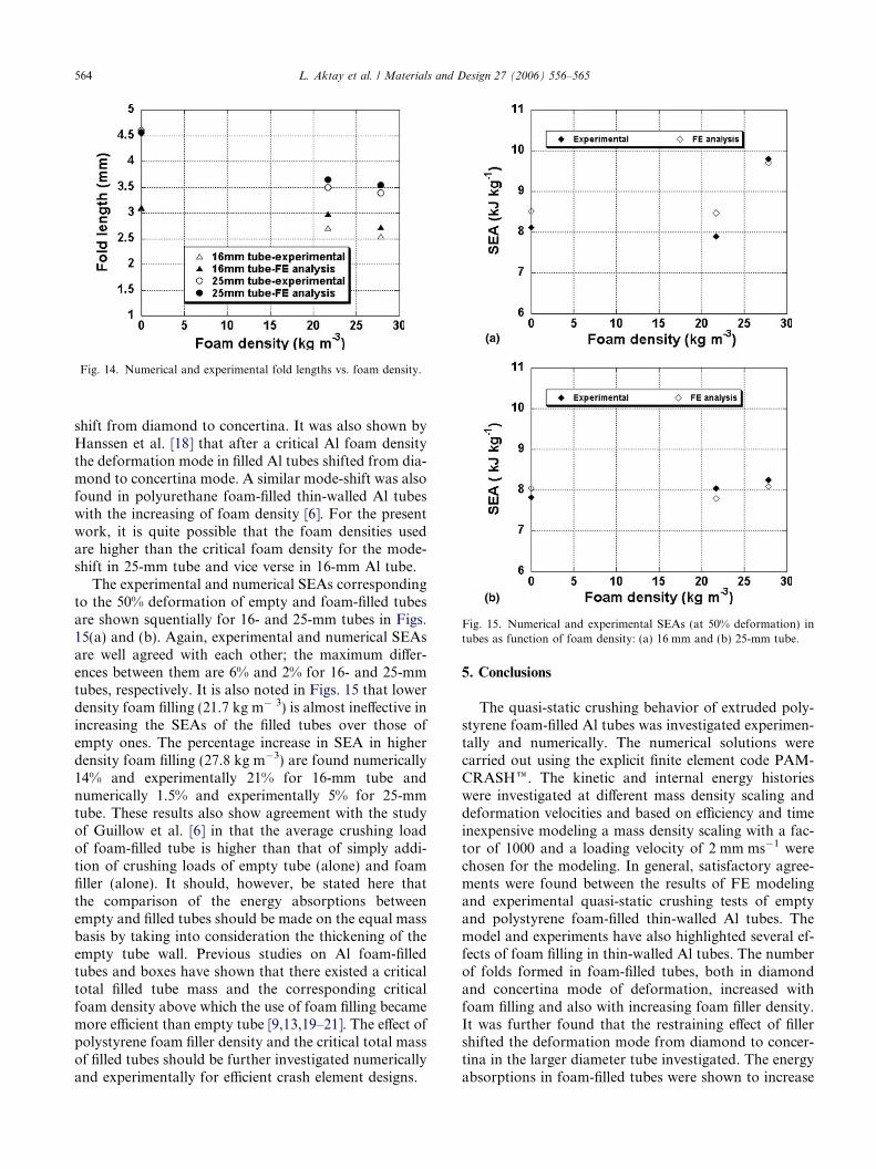
Fig. 14. Numerical and experimental fold lengths vs. foam density.
Fig. 15. Numerical and experimental SEAs (at 50% deformation) intubes as function of foam density: (a) 16 mm and (b) 25-mm tube.
564 L. Aktay et al. / Materials and Design 27 (2006) 556–565
shift from diamond to concertina. It was also shown byHanssen et al. [18] that after a critical Al foam densitythe deformation mode in filled Al tubes shifted from dia-mond to concertina mode. A similar mode-shift was alsofound in polyurethane foam-filled thin-walled Al tubeswith the increasing of foam density [6]. For the presentwork, it is quite possible that the foam densities usedare higher than the critical foam density for the mode-shift in 25-mm tube and vice verse in 16-mm Al tube.
The experimental and numerical SEAs correspondingto the 50% deformation of empty and foam-filled tubesare shown squentially for 16- and 25-mm tubes in Figs.15(a) and (b). Again, experimental and numerical SEAsare well agreed with each other; the maximum differ-ences between them are 6% and 2% for 16- and 25-mmtubes, respectively. It is also noted in Figs. 15 that lowerdensity foam filling (21.7 kg m� 3) is almost ineffective inincreasing the SEAs of the filled tubes over those ofempty ones. The percentage increase in SEA in higherdensity foam filling (27.8 kg m�3) are found numerically14% and experimentally 21% for 16-mm tube andnumerically 1.5% and experimentally 5% for 25-mmtube. These results also show agreement with the studyof Guillow et al. [6] in that the average crushing loadof foam-filled tube is higher than that of simply addi-tion of crushing loads of empty tube (alone) and foamfiller (alone). It should, however, be stated here thatthe comparison of the energy absorptions betweenempty and filled tubes should be made on the equal massbasis by taking into consideration the thickening of theempty tube wall. Previous studies on Al foam-filledtubes and boxes have shown that there existed a criticaltotal filled tube mass and the corresponding criticalfoam density above which the use of foam filling becamemore efficient than empty tube [9,13,19–21]. The effect ofpolystyrene foam filler density and the critical total massof filled tubes should be further investigated numericallyand experimentally for efficient crash element designs.
5. Conclusions
The quasi-static crushing behavior of extruded poly-styrene foam-filled Al tubes was investigated experimen-tally and numerically. The numerical solutions werecarried out using the explicit finite element code PAM-CRASHe. The kinetic and internal energy historieswere investigated at different mass density scaling anddeformation velocities and based on efficiency and timeinexpensive modeling a mass density scaling with a fac-tor of 1000 and a loading velocity of 2 mm ms�1 werechosen for the modeling. In general, satisfactory agree-ments were found between the results of FE modelingand experimental quasi-static crushing tests of emptyand polystyrene foam-filled thin-walled Al tubes. Themodel and experiments have also highlighted several ef-fects of foam filling in thin-walled Al tubes. The numberof folds formed in foam-filled tubes, both in diamondand concertina mode of deformation, increased withfoam filling and also with increasing foam filler density.It was further found that the restraining effect of fillershifted the deformation mode from diamond to concer-tina in the larger diameter tube investigated. The energyabsorptions in foam-filled tubes were shown to increase

L. Aktay et al. / Materials and Design 27 (2006) 556–565 565
with increasing filler density and higher than the sum ofthe energy absorptions of empty tube (alone) and filler(alone).
Acknowledgments
The authors thank the Scientific and Technical Coun-cil of Turkey (TUBITAK) for the Grant #MISAG-227.
References
[1] Alexander JM. An approximate analysis of collapse of thin-walledcylindrical shells under axial loading. Q J Mech Appl Math1960;13:1–9.
[2] Alghamdi AAA. Collapsible impact energy absorbers: an over-view. Thin Wall Struct 2001;39:189–213.
[3] Thornton PH. Energy absorptions by foam filled structures. SAEpaper 800372; 1980.
[4] Lampinen BH. Jeryan RA. Effectiveness of polyurethane foam inenergy absorbing structures. SAE paper 820494; 1982.
[5] Reid SR, Reddy TY, Gray MD. Static and dynamic axialcrushing of foam filled sheet metal tubes. Int J Mech Sci1986;23:295–322.
[6] Guillow SR, Lu G, Grezbieta RH. Quasi-static compression ofthin-walled circular aluminum tubes. Int J Mech Sci2001;43:2103–23.
[7] Reddy TY, Wall RJ. Axial compression of foam filled thin-walledcircular tubes. Int J Impact Eng 1988;7:151–66.
[8] Seitzberger M, Rammerstorfer FG, Gradinger R, Degischer HP,Blaimschein M, Walch C. Experimental studies on the quasi-staticaxial crushing of steel columns filled with aluminum foam. Int JSolids Struct 2000;37:4125–47.
[9] Santosa S,Wierzbicki T. Crash behavior of box columns filled withaluminum honeycomb or foam. Comput Stuct 1998;68:343–67.
[10] Santosa S, Wierzbicki T, Hanssen AG, Langseth M. Experimentaland numerical studies of foam-filled sections. Int J Impact Eng2000;24:509–34.
[11] Toksoy AK. Quasi static axial compression behavior of emptyand polystyrene foam-filled aluminum tubes. Master thesis,Department of Mechanical Engineering, Izmir Institute of Tech-nology; 2003.
[12] Singace AA, El-Sobky H. Interplay of factors influencing collapsemodes in axially crushed tubes. Int J Crash 2000;5:279–97.
[13] Seitzberger M, Rammerstorfer FG, Degischer HP. Crushing ofaxially compressed steel tubes filled with aluminum foam. ActaMech 1997;125:93–105.
[14] Andrews KRF, England GL, Ghani E. Classification of the axialcollapse of cylindrical tubes under quasi-static loading. Int J MechSci 1982;25:687–96.
[15] Hanssen AG, Langseth M, Hopperstad OP. Static and dynamiccrushing of square aluminium extrusions with aluminum foamfiller. Int J Impact Eng 2000;24:347–83.
[16] Hanssen AG, Hopperstad OS, Langseth M. Design of aluminumfoam-filled crash boxes square and circular cross-sections. Int JCrash 2001;6:177–88.
[17] Singace AA. Collapse behaviour of plastic tubes filled with woodsawdust. Thin Wall Sturct 2000;37:163–87.
[18] Hanssen AG, Langseth M, Hopperstad OP. Static and dynamiccrushing of circular aluminum extrusions with aluminum foamfiller. Int J Impact Eng 2000;24:475–507.
[19] Toksoy AK, Guden M, Tanoglu M, Hall IW. Effect of adhesiveon the strengthening of foam-filled circular tubes. J Mater Sci2004;39:1503–6.
[20] Hanssen AG, Langseth M, Hopperstad OP. Optimum design forenergy absorption of square aluminium columns with aluminumfoam filler. Int J Mech Sci 2001;43:153–76.
[21] Seitzberger M, Willminger S. Application of plastic collapsemechanisms for the axial crushing analysis of tubular steelstructures filled with aluminum foam. Int J Crash 2001;6:165–76.
Copyright © 2022 FDOKUMEN