Automobile cam design - CORE
120
Automobile Cam Desv^n
-
Upload
khangminh22 -
Category
Documents
-
view
1 -
download
0
Transcript of Automobile cam design - CORE
Automobile Cam Desv^n

AUTOMOBILE CAM DESIGN
BY
ADOLPH LINCOLN NELSON
THESIS
FOR THE
DEGREE OF BACHELOR OF SCIENCE
IN
MECHANICAL ENGINEERING
COLLEGE OF ENGINEERING
UNIVERSITY OF ILLINOIS
1916

Digitized by the Internet Archive
in 2013
http://archive.org/details/automobilecamdesOOnels
UNIVERSITY OF ILLINOISto
O
.....mj 22, 191 6
THIS IS TO CERTIFY THAT THE THESIS PREPARED UNDER MY SUPERVISION BY
Ado lph...Line o ln...Nels on
ENTITLED Automobile.. ..Cam. Design
IS APPROVED BY ME AS FULFILLING THIS PART OF THE REQUIREMENTS FOR THE
DEGREE OF Bachelor of Science
in Mechanical Engineering
APPROVED:
Instructor in Charge
HEAD OF DEPARTMENT OF...i:e.chani.cal... Engine exlng

UiUC
J
TABLE 0* CONTENTS
CHAPTEP I. THE TANGENTIAL CAMPage
Art. 1. Preliminary Statement 1
2. The valve Spring Portion of the Accelerated Weight . 3
3. The Tangential Cam Motion 4
4. The Lower Motion 4
5. The Upper Motion 7
6. The Inertia Forces 9
7. The Vertical Reaction Between the Cam and the Tappet 10
8. Valve Spring Pressure Required 11
9. Maximum Reaction on the Camshaft 13
10. The Cam Contour Formulae 13
CHAPTER II. THF MU8HP00M FOLLOWER 0AW
Art. 11. The Mushroom Follower Cam Motion 16
12. The Lower Motion 16
13. The Upper Motion 17
14. The Inertia Forces 18
15. The Inertia Reaction and Valve Spring PressureRequired 19
16. Maximum Reaction on the Camshaft 19
17. The Cam Contour Formulae 21
CHAPTER III. THE UNIFORM ACCELERATION CAM
Art. 18. The Uniform Acceleration Cam Motion 23
19. Formulae of the Cam Motion 25
20. Inertia Porce and Required Spring Pressure 25
21. General Equations for the Cam at any Position .... 26
22. The Reaction 27
-II-
PageArt. 33. Relative Noise Factor and Sensitiveness of the Valve
Timing* 28
CHAPTER IV. EXAMPLES TO ILI.U8-TPATE THE APPLICATION 0^ TPE THEORY 0^ THE OA" MOTIONS
Art. 24. Conditions Assumed for Examples 30
The Tangential Cam
25. The Tangential Cam Data 32
26. Valve Spring Pressure Required 33
27. Maximum Reaction on the Camshaft 33
28. Maximum Side Thurst after the Valve is Open .... 34
29. Valve Action Noise Factors 34
30. Sensitiveness of the Valve Timing 35
Mushroom Follower Cam
31. The Mushroom Follower Cam Data 35
32. Valve Spring Pressure Required 36
33. Maximum Peaction on the Camshaft 36
34. Valve Action Noise Factor 37
35. Sensitiveness of the Valve Timing 37
Uniform Accelerat ion Cam
36. Uniform Acceleration Cam Data 38
37. Valve Spring Pressure Required 39
38. Maximum Peaction on the Camshaft 39
39. valve Action Noise Factors 39
40. Sensitiveness of the Valve Timing 40
Applies to all types of cams
-III-
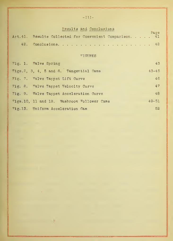
Resu lt e and Conclusi onePage
Art. 41. Results Collected for Convenient Comparison 41
42. Conclusions 42
FIGURES
Fig. 1. valve Spring 43
Figs. 2, 3, 4, 5 and 6. Tangential Cams 43-45
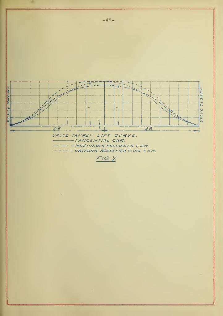
Fig. 7. valve Tappet Lift Curve 46
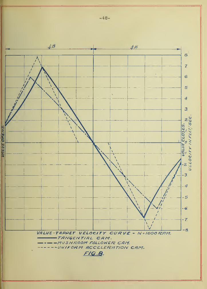
Fig. 8. lralve Tappet Velocity Curve 47
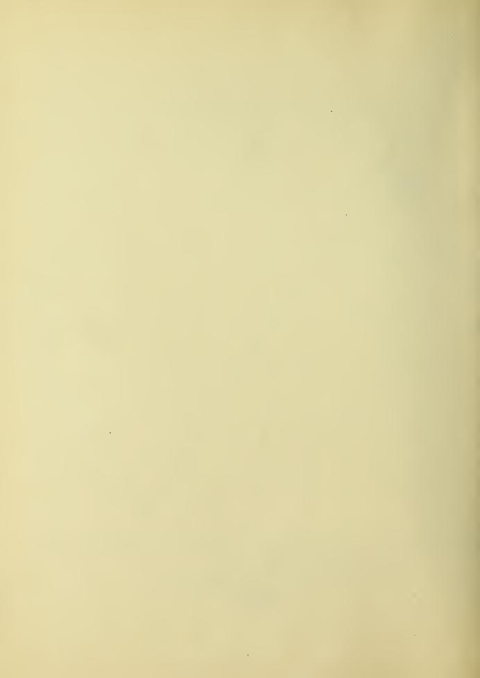
"Fig. 9. Valve Tappet Acceleration Curve 48
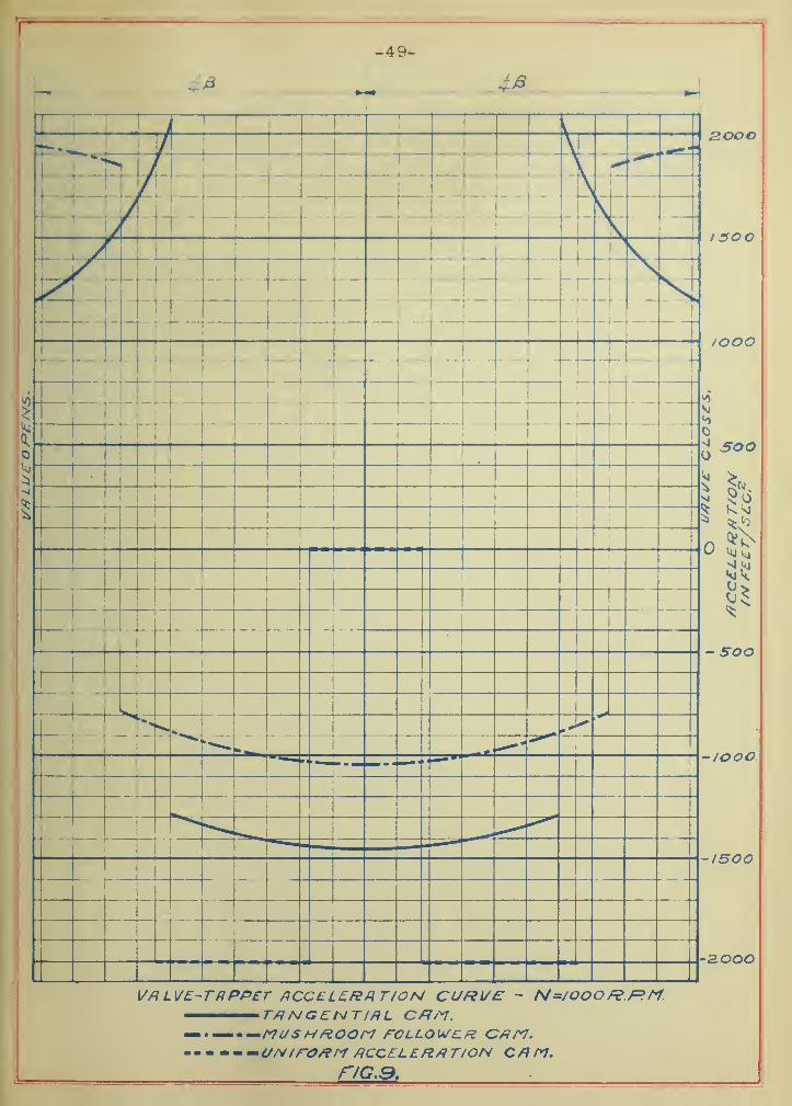
rigs.lO, 11 and 12. Mushroom follower Cams 49-51
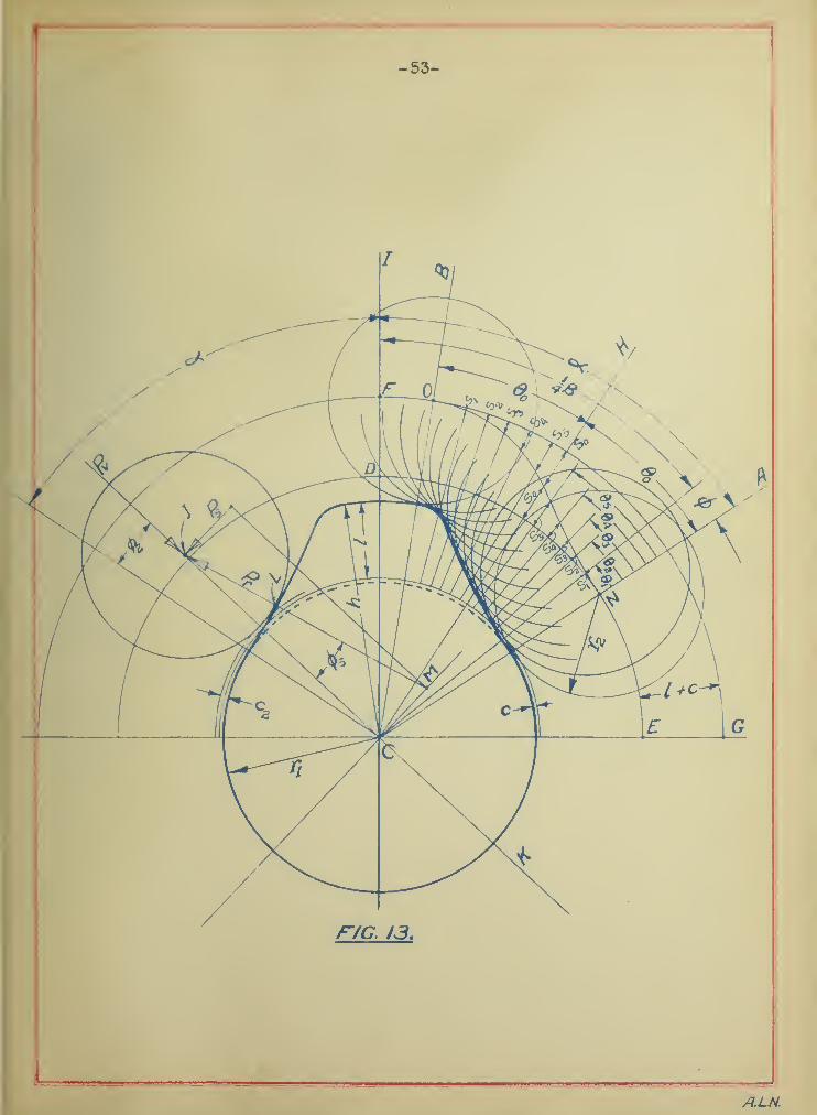
Fig.l3. Uniform Acceleration Cam 52
ft
AUTOMOBILE CAW DE8IOT
theory and Practioal Application of the Motion of the TwoGeneral Types of Cams Used in American Automobile
Motors, and the Type Largely Used inEuropean Motors)
CHAPTER I. THE TANGENTIAL CAM
1. Preliminary Statement
The two general types of cams used in American gasoline
motors are the ones known as the tangential and the mushroom fol-
lower cams; while the c^ra so largely used in Europe is known as th
uniform acceleration cam. These names follow from the nature of
the cam contour or from the motion that is produced. The tangen-
tial cam has straight faces tangent to the base-circle of the cam,
the mushroom follower cam has convex faces of a large radius tan-
gent to the base circle, and the uniform acceleration which is im-
plied by the name the cam takes. The contours of the two former
carts are geometrically regular with accompanying motions as the
cams may give, while the contour of the latter is irregular (that
is a constantly changing curvature) giving a preassigned uniformly
accelerated motion.
It is the object of this discussion to make a complete
analysis of the motion of these three types of cams, in order to
bring out all the essential properties of each type, that compari-
sons may be made as to their relative merits; and to point out the
most important general factors that are the basis of the resulting
motions given to the valve mechanism by the cam. To make the
attempted thoroughness of this discussion self-evident, a minimum
-2-
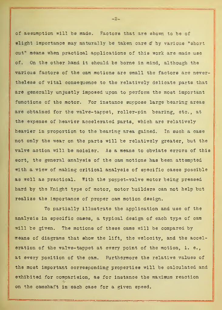
of assumption will be made. Factors that are shown to be of
slight importance may naturally be taken care cf by various "short
cut" means when practical applications of this work are made use
of. On the other hand it should be borne in mind, although the
various factors of the cam motions are small the factors are never-
theless of vital consequence to the relatively delicate parts that
are generally unjustly imposed upon to perform the most important
functions of the motor. For instance suppose large bearing areas
are obtained for the valve- tappet, roller-pin bearing, etc., at
the expense of heavier accelerated parts, which are relatively
heavier in proportion to the bearing area gained. In such a case
not only the wear on the parts will be relatively greater, but the
valve action will be noisier. As a means to obviate errors of this
sort, the general analysis of the cam motions has been attempted
with a view of making critical analysis of specific cases possible
as well as practical. With the poppet-valve motor being pressed
hard by the Knight type of motor, motor builders can not help but
realize the importance of proper cam motion design.
To partially illustrate the application and use of the
analysis in specific cases, a typical design of each type of cam
will be given. The motions of these cams will be compared by
means of diagrams that show the lift, the velocity, and the accel-
eration of the valve- tappet at every point of the motion, i. e.,
at every position of the cam. Furthermore the relative values of
the most important corresponding properties will be calculated and
exhibited for comparision, as for instance the maximum reaction
on the camshaft in each case for a given speed.
-3-
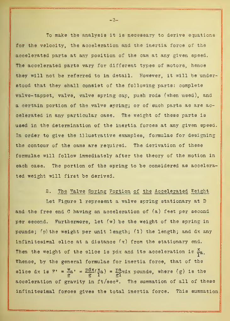
To make the analysis it is necessary to derive equations
for the velocity, the acceleration and the inertia force of the
accelerated parts at any position of the cam at any given speed.
The accelerated parts vary for different types of motors, hence
they will not be referred to in detail. However, it will be under-
stood that they shall consist of the following parts: complete
valve- tappet, valve, valve spring cap, push rods (when used), and
a certain portion of the valve spring; or of such parts as are ac-
celerated in any particular case. The weight of these parts is
used in the determination of the inertia forces at any given speed.
In order to give the illustrative examples, formulae for designing
the contour of the cams are required. The derivation of these
formulae will follow immediately after the theory of the motion in
each case. The portion of the spring to be considered as accelera-
ted weight will first be derived.
2 » The Valve Spring Portion of the Accelerated Weight
Let Figure 1 represent a valve spring stationary at D
and the free end C having an acceleration of fa) feet per second
per second. Furthermore, let (w) be the weight of the spring in
pounds; f p) the weight per unit length; (1) the length; and dx any
infinitesimal slice at a distance f x) from the stationary end.
Then the weight of the slice is pdx and its acceleration is x-a<
Whence, by the general formulae for inertia force, that of the
slice dx is F' = = £^fZa ) = Ef-xdx pounds, where (g) is theg g 1 gl
acceleration of gravity in ft/sec 3. The summation of all of these
infinitesimal forces gives the total inertia force. This summation
-4-
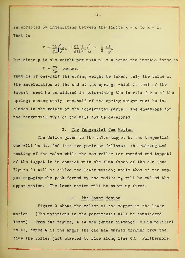
is effected by integrating between the limits x = o to x = 1.
That is
But since p is the weight per unit pi = w hence the inertia force is
F 22: pounds.2g
That is if one-half the spring weight be taken, only the value of
the acceleration at the end of the spring, which is that of the
tappet, need be considered in determining the inertia force of the
spring; consequently, one-half of the spring weight must be in-
cluded in the weight of the accelerated parts. The equations for
the tangential type of cam will now be developed.
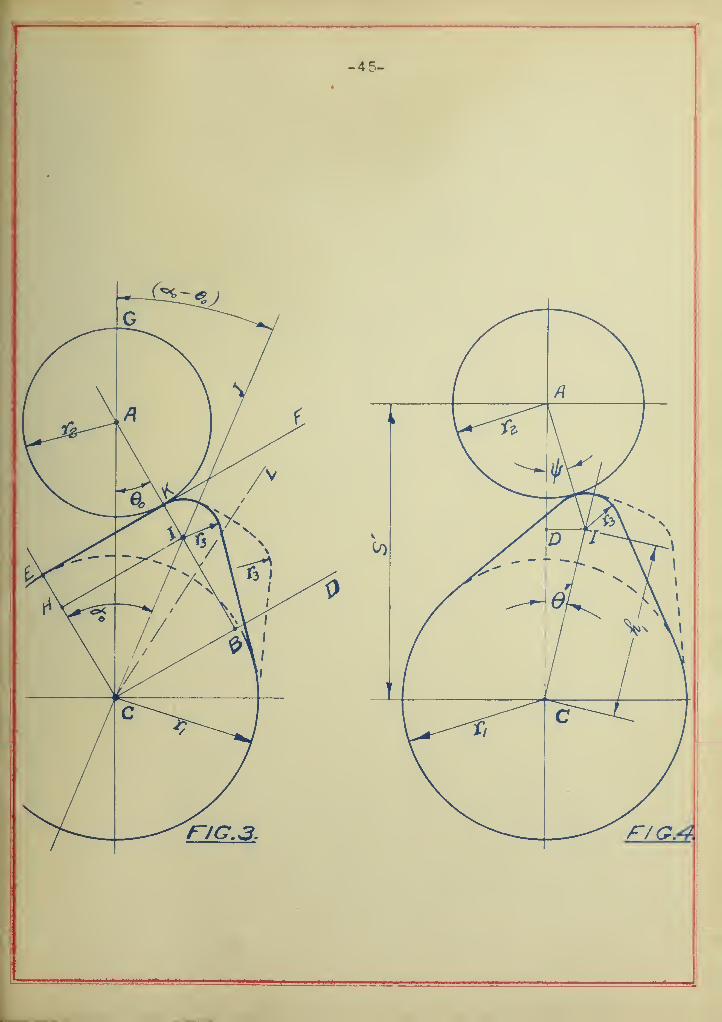
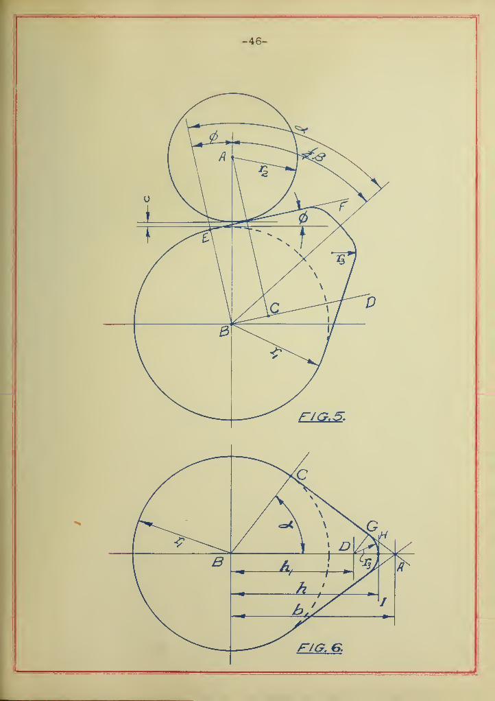
3. The Tangential Cam Motion
The Motion given to the valve-tappet by the tengential
cam will be divided into two parts as follows: the raising and
seating of the valve while the cam roller (or rounded end tappet)
of the tappet is in contact with the flat faces of the cam (see
Figure 2) will be called the lower motion; while that of the tap-
pet engaging the peak formed by the radius r3
will be called the
upper motion. The lower motion will be taken up first.
4. The Lower Motion
Figure 2 shows the roller of the tappet in the lower
motion. (The notations in the parenthesis will be considered
later). From the figure, s is the center distance, CD is parallel
to EF, hence Q is the angle the cam has turned through from the
time the roller just started to rise along line CG. Furthermore,
-5-
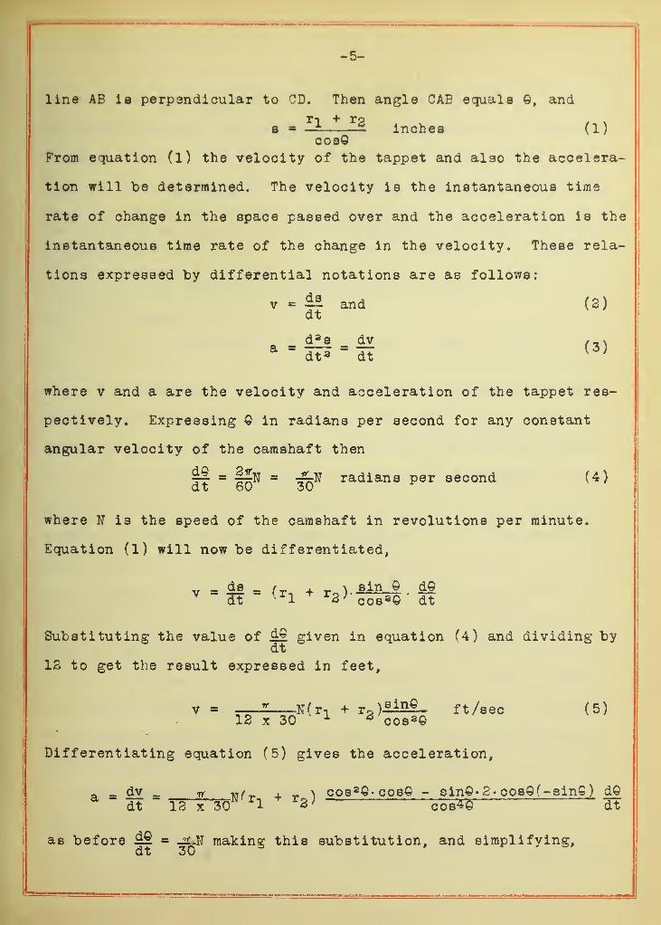
line AE is perpendicular to CD. Then angle CAE equals ©, and
a - f1 * r3inches (1)
cosOFrom equation (1) the velocity of the tappet and also the accelera-
tion will be determined. The velocity is the instantaneous time
rate of change in the space passed over and the acceleration is the
instantaneous time rate of the change in the velocity. These rela-
tions expressed by differential notations are as follows:
v ds and (2)dt
where v and a are the velocity and acceleration of the tappet res-
pectively. Expressing © in radians per second for any constant
angular velocity of the camshaft then
= flfl = radians per second (4)dt 60 30
where W is the speed of the camshaft in revolutions per minute.
Equation (1) will now be differentiated,
,r _ de _ /_ . _ \ sin Q d©
Substituting the value of ^£ given in equation (4) and dividing bydt
12 to get the result expressed in feet,
v « 2 N(n + rP )£i££- ft /sec (5)12 x 30 1 2 cos 3©
Differentiating equation (5) gives the acceleration,
a dv _ ff w /_ , _ \ cos 2©- cos© - sin©» 2- cosQf-ein©) d©a " dt " 12 x 30N r
l+ r3 j cob*5 dt
as before M = making this substitution, and simplifying,dt 30
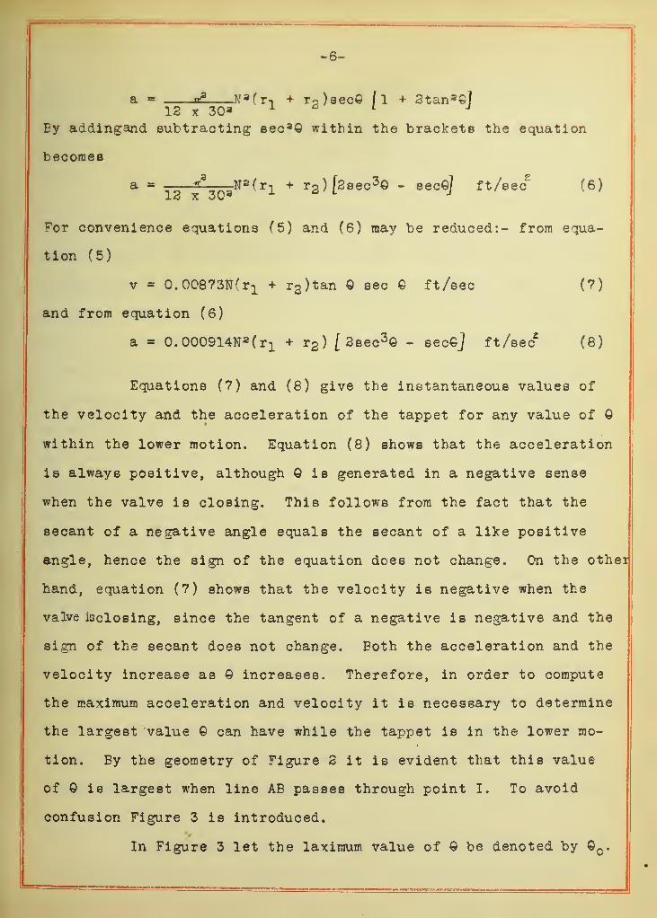
a = a* N^r-i + r P )sec© fl + 2tan 3©J
12 x 30 a 1 * 1 J
Ey addingand subtracting see 3© within the brackets the equation
becomes
a ^, N a (r-! + r2 )[2sec
3© - sec©) ft /sec2
(6)13 x 30 3 o
' l j
For convenience equations (5) and (6) may be reduced:- from equa-
tion (5)
v = 0.00873^(x1 + r2 )tan © sec © ft/sec (7)
and from equation (6)
a = O.OOO^N^r! + r2 ) [ 2sec3© - eec©J ft/sec2
(8)
Equations (7) and (8) give the instantaneous values of
the velocity and the acceleration of the tappet for any value of ©
within the lower motion. Equation (8) shows that the acceleration
is always positive, although © is generated in a negative sense
when the valve is closing. This follows from the fact that the
secant of a negative angle equals the secant of a like positive
angle, hence the sign of the equation does not change. On the othei
hand, equation (7) shows that the velocity is negative when the
valve iscloeing, since the tangent of a negative is negative and the
sign of the secant dees not change. Both the acceleration and the
velocity increase as © increases. Therefore, in order to compute
the maximum acceleration and velocity it is necessary to determine
the largest value © can have while the tappet is in the lower mo-
tion. By the geometry of Figure 2 it is evident that this value
of Q is largest when line AB passes through point I. To avoid
confusion Figure 3 is introduced.
In Figure 3 let the laximum value of © be denoted by ©c .
-7-
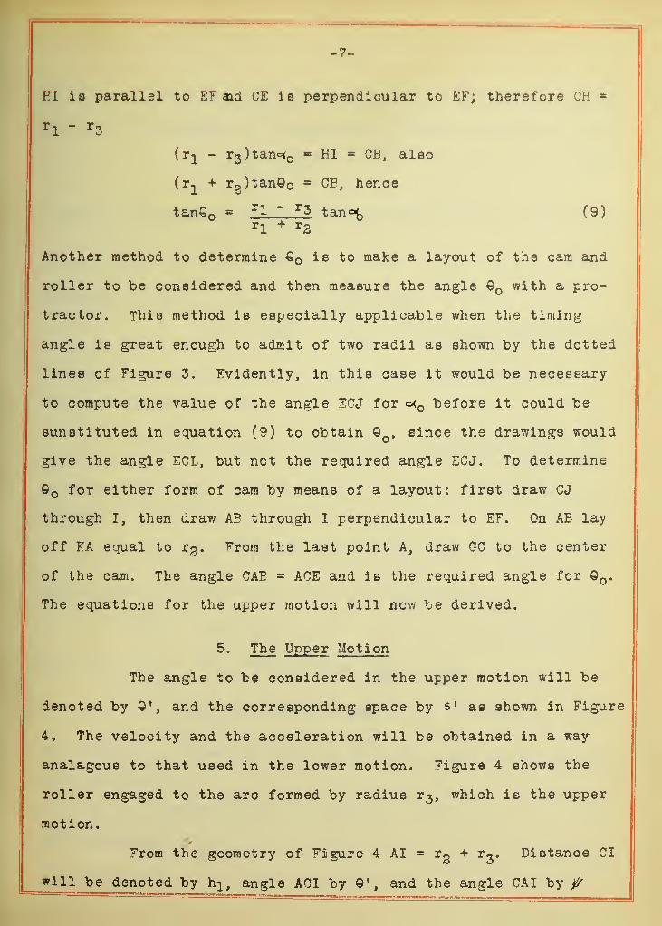
FI is parallel to EF aid CE is perpendicular to EF; therefore CH
rl ~ r
3
(r^ - r3)tan°< = HI = CE, aleo
(r^ + rg)tan©o CE, hence
tan€ = rl ~ r3 tan«fc (9)rl
+ r2
Another method to determine Q is to make a layout of the cam and
roller to be considered and then measure the angle Q with a pro-
tractor. This method is especially applicable when the timing
angle is great enough to admit of two radii as shown by the dotted
lines of Figure 3. Evidently, in this case it would be necessary
to compute the value of the angle ECJ for «=^ before it could be
sunstituted in equation (9) to obtain © , since the drawings would
give the angle ECL, but not the required angle ECJ. To determine
o for either form of cam by means of a layout: first draw CJ
through I, then draw AE through I perpendicular to EF. On AB lay
off KA equal to r%. From the last point A, draw GC to the center
of the cam. The angle CAE = ACE and is the required angle for © .
The equations for the upper motion will now be derived.
5. The Upper Motion
The angle to be considered in the upper motion will be
denoted by and the corresponding space by s' as shown in Figure
4. The velocity and the acceleration will be obtained in a way
analagoue to that used in the lower motion. Figure 4 shows the
roller engaged to the arc formed by radius r3 , which is the upper
motion.
From the geometry of Figure 4 AI = r2
+ r3
. Distance CI
will be denoted by h}, angle ACI by and the angle CAI by ^

-8-
In order to obtain an equation for s 1 that will differentiate readi-
ly, & will be expressed in terms of 0'. From the theorem of sines
sinQ' _ sin fr2 +r3 h
x(10)
However, the angles considered here are small, hence it follows that
t - ^ ©' (IDr2
+ r3
In Figure 4, ID is perpendicular to AC, then
= h-icos©' + (r2 + r-i)cos/
—
^1 ©•) inches (12)Vr3 + r
3 /
Denoting the velocity and acceleration of the upper motion by v f
and a 1 respectively, then
v» = ILL « L hl sinO» (r2 + r3 )8in/ *1—q)1dt i 1
r2+ r
3 Vr2
+ r3 / J dt
as before ££1 = -2LN and dividing by 12 to get the result expresseddt 30
in feet
v 1 = - £ Nhi rsin© f + sin ( ^—©») ] ft /sec (13)12 x 30 L Vr2 + r3 / J
Differentiating equation (13) gives the acceleration,
a' = $SL = . —=—aJooeS- —-^-ooe (-^~o)]dt 12 x 30 1 L r2 + r-i Vr^ + r* / JL r2 + r3 Vr2 + r3 / J dt
Now let hl = k and substituting _£_N for dQ'
r2 + r 3 30 dt
a» « - n? N2h1 [cos© 1 + kcos(ke»)/ ft/sec 3 (14)12 x 30a 1 L J
For convenience equations (13) and (14) may be written as follows:
from Equation (13)
v' = - 0.00873Nh1 [sin©' + sin(k© f
)Jft/sec (15)
and from equation (14)
-9-
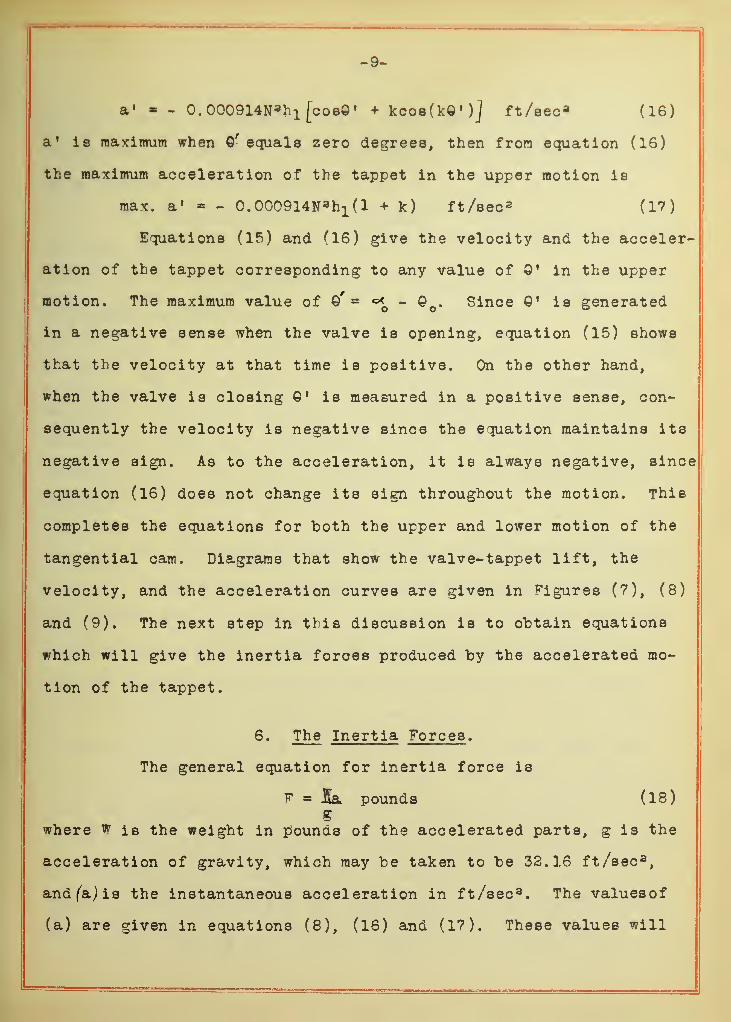
a' «= - 0.000914N 3 h 1 [cos©» + kcos(k«')] ft/eec a (16)
a 1 is maximum when Qrequals zero degrees, then from equation (16)
the maximum acceleration of the tappet in the upper motion is
max. a 1 * - C. 000914N a h1 (1 + k) ft /sec 2 (17)
Equations (15) and (16) give the velocity and the acceler-
ation of the tappet corresponding to any value of ©' in the upper
motion. The maximum value of ©' - - © e . Since Q 1 is generated
in a negative sense when the valve is opening, equation (15) shows
that the velocity at that time is positive. On the other hand,
when the valve is closing © f is measured in a positive sense, con-
sequently the velocity is negative since the equation maintains its
negative sign. As to the acceleration, it is always negative, since
equation (16) does not change its sign throughout the motion. This
completes the equations for both the upper and lower motion of the
tangential cam. Diagrams that show the valve-tappet lift, the
velocity, and the acceleration curves are given in Figures (7), (8)
and (9). The next step in this discussion is to obtain equations
which will give the inertia forces produced by the accelerated mo-
tion of the tappet.
6. The Inertia Forces .
The general equation for inertia force is
F * la pounds (18)g
where w is the weight in pounds of the accelerated parts, g is the
acceleration of gravity, which may be taken to be 32.16 ft/sec 3,
and (a) is the instantaneous acceleration in ft/sec 3. The valuesof
(a) are given in equations (8), (16) and (17). These values will
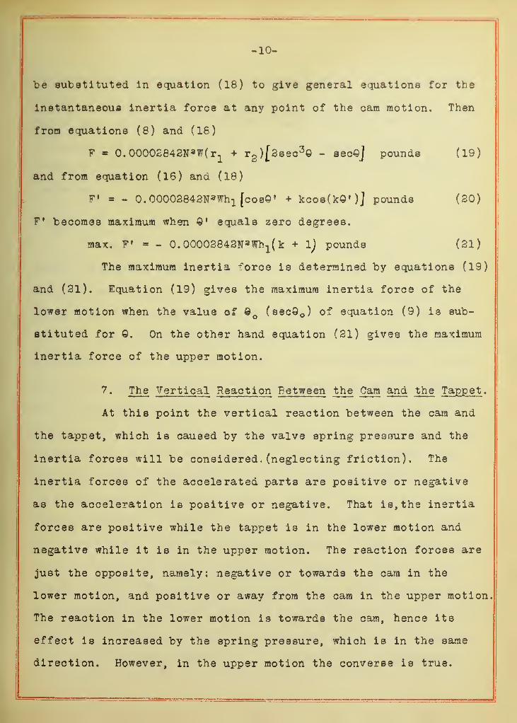
-10-
be substituted in equation (18) to give general equations for the
instantaneous inertia force at any point of the cam motion. Then
from equations (8) and (18)
F * 0.00002842N aW(r1
+ r2)[2sec 3© - sec«J pounds (19)
and from equation (16) and (18)
f* = « 0.00003843N»Wh1 [cob© 1 + kcosOcQ')] pounds (20)
F' becomes maximum when ©• equals zero degrees.
max. F' - - 0.00002842N*Wh1(k + 1) pounds (21)
The maximum inertia ^oroe is determined by equations (19)
and (21). Equation (19) gives the maximum inertia force of the
lower motion when the value of © c(sec0 o ) of equation (9) is sub-
stituted for ©. On the other hand equation (21) gives the maximum
inertia force of the upper motion.
7. The Vertical Reaction Between the Cam and the Tappet .
At this point the vertical reaction between the cam and
the tappet, which is caused by the valve spring pressure and the
inertia forces will be considered. (neglecting friction). The
inertia forces of the accelerated parts are positive or negative
as the acceleration is positive or negative. That is, the inertia
forces are positive while the tappet is in the lower motion and
negative while it is in the upper motion. The reaction forces are
just the opposite, namely: negative or towards the cam in the
lower motion, and positive or away from the cam in the upper motion.
The reaction in the lower motion is towards the cam, hence its
effect is increased by the spring pressure, which is in the same
direction. However, in the upper motion the converse is true.
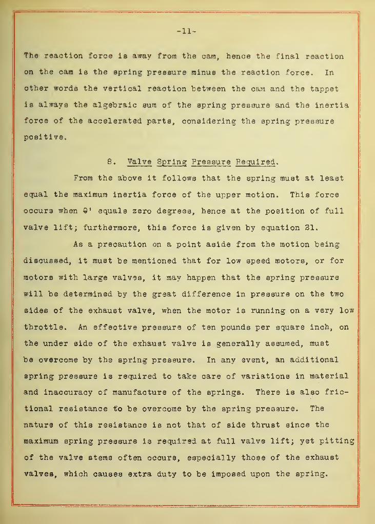
-11-
The reaction force is away from the cam, hence the final reaction
on the cam is the spring pressure minus the reaction force. In
other words the vertical reaction between the cam and the tappet
is always the algebraic sura of the spring pressure and the inertia
force of the accelerated parts, considering the spring pressure
positive.
8. Valve Spring Pressur e Required .
From the above it follows that the spring must at least
equal the maximum inertia force of the upper motion. This force
occurs when 1 equals zero degrees, hence at the position of full
valve lift; furthermore, this force is given by equation 31.
As a precaution on a point aside from the motion being
discussed, it must be mentioned that for low speed motors, or for
motors with large valves, it may happen that the spring pressure
will be determined by the great difference in pressure on the two
sides of the exhaust valve, when the motor is running on a very low
throttle. An effective pressure of ten pounds per square inch, on
the under side of the exhaust valve is generally assumed, must
be overcome by the spring pressure. In any event, an additional
spring pressure is required to take care of variations in material
and inaccuracy of manufacture of the springs. There is also fric-
tional resistance to be overcome by the spring pressure. The
nature of this resistance is not that of side thrust since the
maximum spring pressure is required at full valve lift; yet pitting
of the valve stems often occurs, especially those of the exhaust
valves, which causes extra duty to be imposed upon the spring.
-12-
For such cases precedent and experience must be relied upon to
suggest the most practical additional spring pressure.
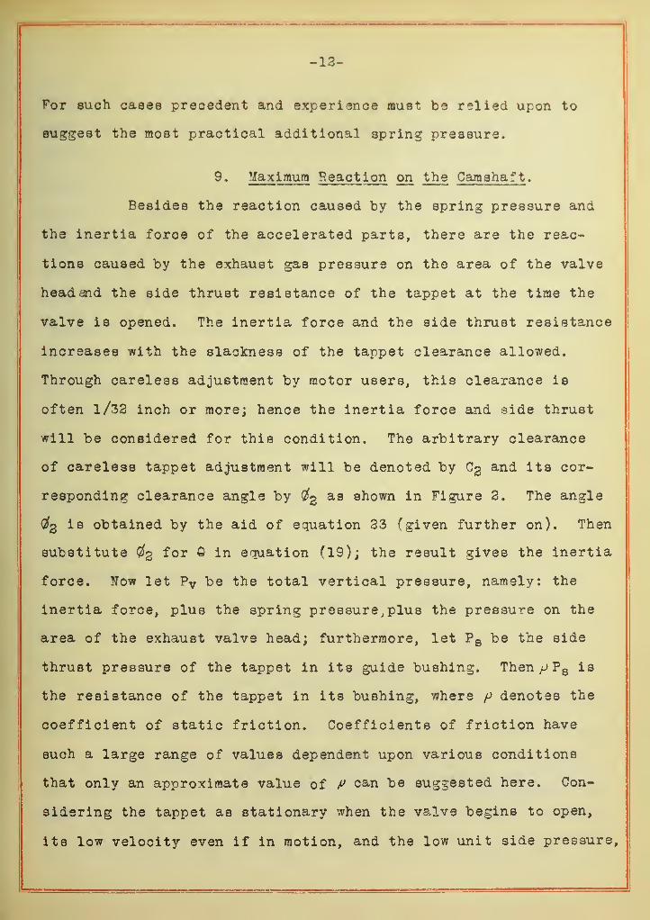
9. Maximum Reaction on the Camshaft .
Besides the reaction caused by the spring pressure and
the inertia force of the accelerated parts, there are the reac-
tions caused by the exhaust gas pressure on the area of the valve
head and the side thrust resistance of the tappet at the time the
valve is opened. The inertia force and the side thrust resistance
increases with the slackness of the tappet clearance allowed.
Through careless adjustment by motor users, this clearance is
often l/33 inch or more; hence the inertia force and side thrust
will be considered for this condition. The arbitrary clearance
of careless tappet adjustment will be denoted by C3 and its cor-
responding clearance angle by #g as shown in Figure 3. The angle
#2 is obtained by the aid of equation 23 (given further on). Then
substitute Cfg ^or ^ *n equation (19); the result gives the inertia
force. Now let Pv be the total vertical pressure, namely: the
inertia force, plus the spring pressure, plus the pressure on the
area of the exhaust valve head; furthermore, let P 8 be the side
thrust pressure of the tappet in its guide bushing. Then^>P8 is
the resistance of the tappet in its bushing, where p denotes the
coefficient of static friction. Coefficients of friction have
such a large range of values dependent upon various conditions
that only an approximate value of P oa,n be suggested here. Con-
sidering the tappet as stationary when the valve begins to open,
its low velocity even if in motion, and the low unit side pressure,
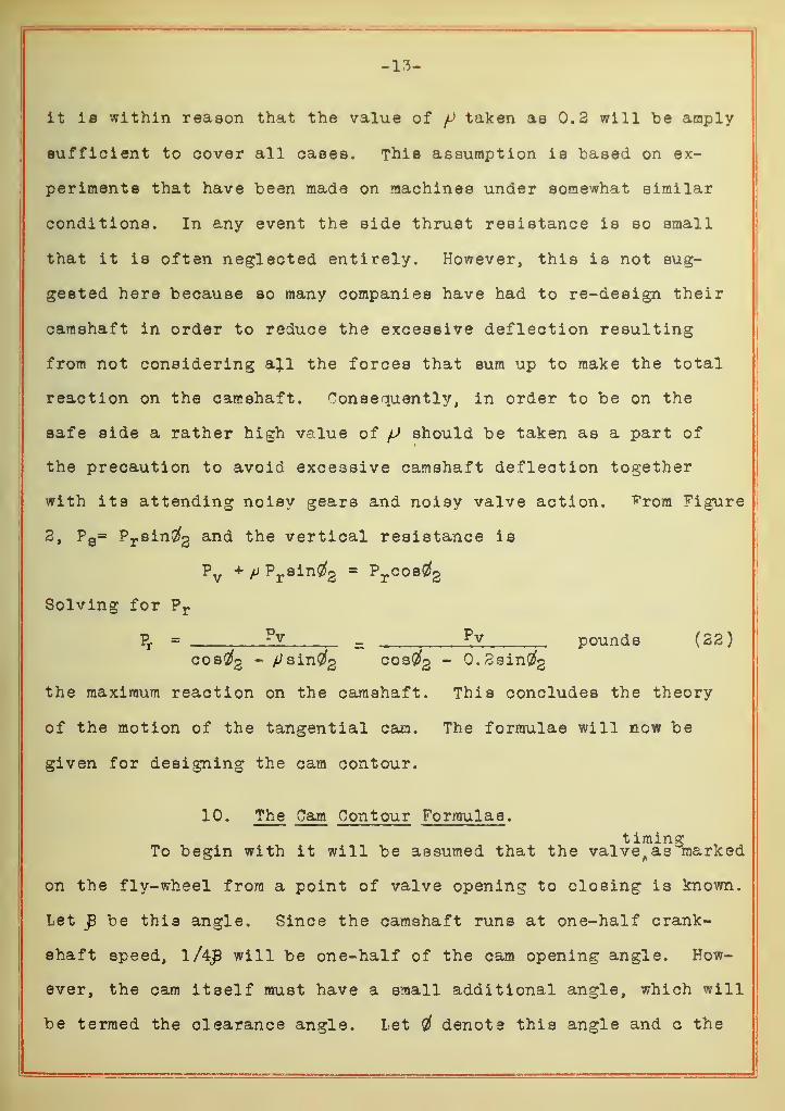
-13-
it is within reason that the value of f>taken as 0.2 will be amply
sufficient to cover all cases. This assumption is based on ex-
periments that have been made on machines under somewhat similar
conditions. In any event the side thrust resistance is so small
that it is often neglected entirely. However, this is not sug-
gested here because so many companies have had to re-design their
camshaft in order to reduce the excessive deflection resulting
from not considering a}.l the forces that sum up to make the total
reaction on the camshaft. Consequently, in order to be on the
safe side a rather high value of (J should be taken as a part of
the precaution to avoid excessive camshaft deflection together
with its attending noisy gears and noisy valve action, ^rom Figure
2, P s= Pr sin#2 and the vertical resistance is
Pv + p Prsin#2 - Prcos#2
Solving for Pr
Pr = pv _ £v pounds (22)cos#2 - /tfsinCfg cosCfg - 0.2sin#2
the maximum reaction on the camshaft. This concludes the theory
of the motion of the tangential cam. The formulae will now be
given for designing the cam contour.
10. The Cam Contour Formulae .
timingTo begin with it will be assumed that the valve^as marked
on the fly-wheel from a point of valve opening to closing is known.
Let p be this angle. Since the camshaft runs at one-half crank-
shaft speed, l/4£ will be one-half of the cam opening angle. How-
ever, the cam itself must have a small additional angle, which will
be termed the clearance angle. Let denote this angle and c the
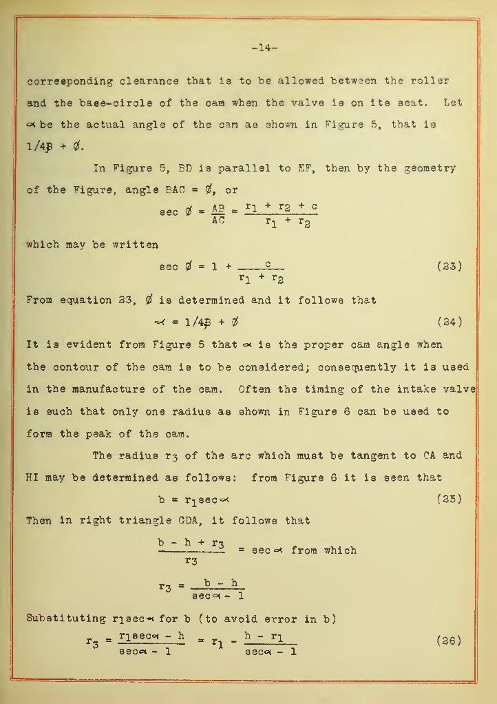
-14-
corresponding clearance that ia to "be allowed between the roller
and the base-circle of the cam when the valve ia on ita aeat. Let
<x be the actual angle of the cam aa shown in Figure 5, that ia
lAp + 0.
In figure 5, ED i3 parallel to EF, then by the geometry
of the Figure, angle PAO = or
sec $ = M = r* * r S + c
AC r1
+ r2
which may be written
sec $ - 1 + 2 (23)rl
+ r2
From equation 23, is determined and it follows that
=4 = l/4£ + # (24)
It is evident from Figure 5 that <=* is the proper cam angle when
the contour of the cam is to be considered; consequently it is used
in the manufacture of the cam. Often the timing of the intake valve
is such that only one radius as shown in Figure 6 can be used to
form the peak of the cam.
The radius r3 of the arc which must be tangent to OA and
HI may be determined as follows: from Figure 6 it is seen that
b = r^sec^ (25)
Then in right triangle GDA, it follows that
b - h + r^_ = sec °< from which
*3
r3 - b - heec°< - 1
Substituting risec* for b (to avoid error in b)
r3
= rl secc< - h = n - h ' r l (26)secoi - l sec** - 1

the constant used in equations 15, 16, 17 and 21.
The next step is to derive equations for the motion of the mush-
room follower cam.

-16-
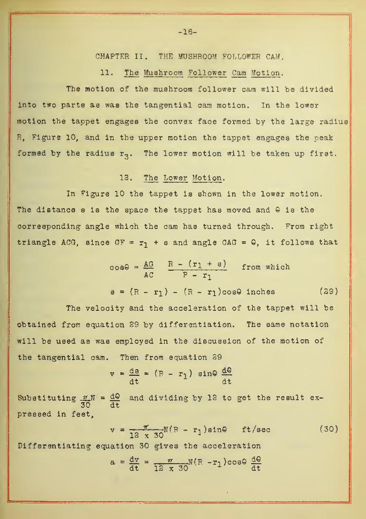
CHAPTFR II. THE MUSHROOM FOLLOWER CAM.
11. The Mushroom Follower Cam Motion .
The motion of the mushroom follower cam will be divided
into two parts as was the tangential cam motion. In the lower
motion the tappet engages the convex face formed by the large radius
R, Figure 10, and in the upper motion the tappet engages the peak
formed by the radius r^. The lower motion will be taken up first.
12. The Lower Motion .
In Figure 10 the tappet is shown in the lower motion.
The distance s is the space the tappet has moved and Q is the
corresponding angle which the cam has turned through. From right
triangle ACG, since GF = r^ + s and angle CAG = 0, it follows that
cose = M R - ( r l + a) from whichAC P - rx
a = (R - ri) - (R - ri)cosO inches (39)
The velocity and the acceleration of the tappet will be
obtained from equation 29 by differentiation. The same notation
will be used as was employed in the discussion of the motion of
the tangential cam. Then from equation 29
v * M * (R - rT ) sin©dt dt
Substituting JLN - dO and dividing by 12 to get the result ex-30 dt
pressed in feet,
v = 2t u( P _ r , ) s ins ft/sec (30)12 x 30 1
Differentiating equation 30 gives the acceleration
a = !l = 2 N(R -r-i )cos©dt 12 x 30
1dt

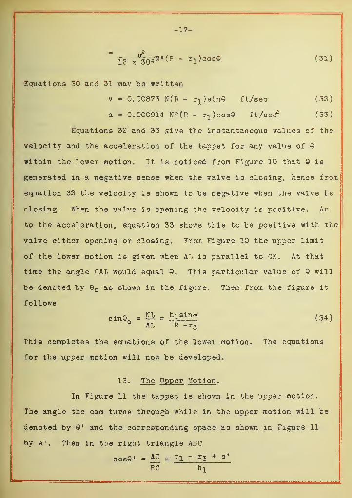
-17-
=
13 x
f
30^N3(R " r1 )coeQ (31)
Equations 30 and 31 may be written
v - 0.00873 N(F - r-^sin© ft/sec (33)
a = 0.000914 N 8 (R - r1 )cos3 ft/sec2 (33)
Equations 33 and 33 give the instantaneous values of the
velocity and the acceleration of the tappet for any value of Q
within the lower motion. It is noticed from Figure 10 that © is
generated in a negative sense when the valve is closing, hence from
equation 33 the velocity is shown to be negative when the valve is
closing. When the valve is opening the velocity is positive. As
to the acceleration, equation 33 shows this to be positive with the
valve either opening or closing. From Figure 10 the upper limit
of the lower motion is given when AL is parallel to CK. At that
time the angle HAL would equal ©. This particular value of © will
be denoted by Q as shown in the figure. Then from the figure it
follows
8in0 . « . hielnoc(34)
° AL F -r3
This completes the equations of the lower motion. The equations
for the upper motion will now be developed.
13. The Upper Motion.
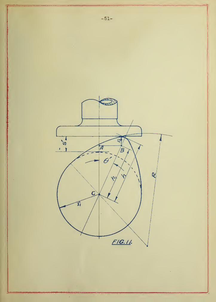
In Figure 11 the tappet is shown in the upper motion.
The angle the cam turns through while in the upper motion will be
denoted by ©' and the corresponding space as shown in Figure 11
by s*. Then in the right triangle ABC
cos©' = Ac = r l ~ r 3 + s '
EC h 1
-18-
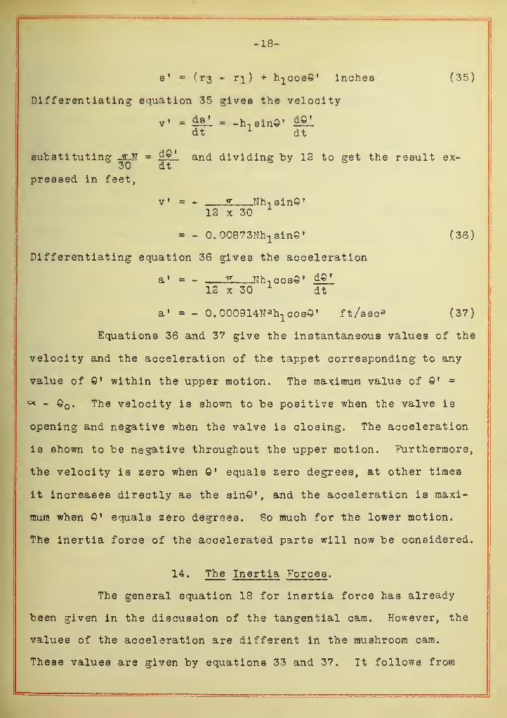
e' = ( r3 - ri ) + h^oos©' inches (35)
Differentiating equation 35 gives the velocity
v» = iS-L = -h n sin©' ££1dt 1
dt
substituting jUT = dQ an(^ dividing "by 12 to get the result ex-30 dt
pressed in feet,
v » = -,
*r ...Nh-isinQ 1
12 x 30
= - 0. 00873^8^© • (36)
Differentiating equation 36 gives the acceleration
a' = -. ,TTh, cos©'
12 x 301
dt
a' = - 0.000914N 3h1cosO l ft/sec 3 (37)
Equations 36 and 37 give the instantaneous values of the
velocity and the acceleration of the tappet corresponding to any
value of ©' within the upper motion. The maximum value of ©' =
°< - © . The velocity is shown to be positive when the valve is
opening and negative when the valve is closing. The acceleration
is shown to be negative throughout the upper motion. "Furthermore,
the velocity is zero when ©' equals zero degrees, at other times
it increases directly as the sin©', and the acceleration is maxi-
mum when ©' equals zero degrees. So much for the lower motion,
The inertia force of the accelerated parts will now be considered.
14. The Inertia "Forces .
The general equation 18 for inertia force has already
been given in the discussion of the tangential cam. However, the
values of the acceleration are different in the mushroom cam.
These values are given by equations 33 and 37. It follows from
-19-
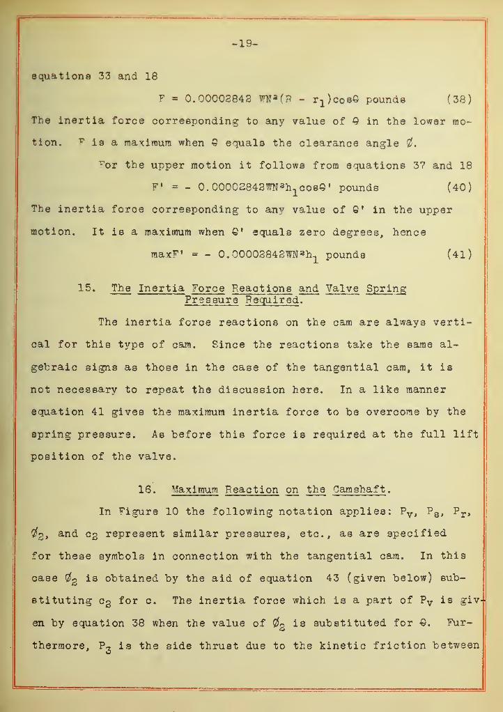
equations 33 and 18
F = 0.00008843 WN a (P - r1 )coB© pounds (38)
The inertia force corresponding to any value of Q in the lower mo-
tion. v is a maximum when Q equals the clearance angle
vot the upper motion it follows from equations 37 and 18
F' = - 0. 00002848WN ah1coBe» pounds (40)
The inertia force corresponding to any value of 0' in the upper
motion. It is a maximum when Q* equals zero degrees, hence
maxF 1 = - 0. 0000S843WN a h1pounds (41)
15. The Inertia Force Reactions and Valve Spring;Pressure Required .
The inertia force reactions on the cam are always verti-
cal for this type of cam. Since the reactions take the same al-
gebraic signs as those in the case of the tangential cam, it is
not necessary to repeat the discussion here. In a like manner
equation 41 gives the maximum inertia force to be overcome by the
spring pressure. As before this force is required at the full lift
position of the valve.
16. Maximum Reaction on the Camshaft .
In Figure 10 the following notation applies: Pv ,P s ,
Pr ,
#2, and eg represent similar pressures, etc., as are specified
for these symbols in connection with the tangential cam. In this
case2 is obtained by the aid of equation 43 (given below) sub-
stituting eg for c. The inertia force which is a part of Pv is giv-
en by equation 38 when the value of 0g is substituted for Q. Fur-
thermore, P- is the side thrust due to the kinetic friction between
-20-
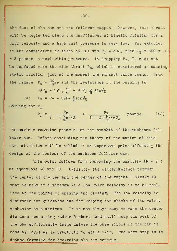
the face of the cam and the follower tappet. However, this thrust
will be neglected since the coefficient of kinetic friction for a
high velocity and a high unit pressure is very low. For example,
if the coefficient be taken as .01 and Pr = 300, then P3
= 300 x .01
= 3 pounds, a negligible pressure. In dropping P3, P3 must not
he confused with the side thrust P a , which is considered as causing
static friction just at the moment the exhaust valve opens. From
the figure, P 8 = -^pr an<* the resistance in the bushing is
2p? e= 2p?T
W = 2pPr I sintfg
Eut Pv = Pr - 2pPr iLsinCfg
Solving for Pr
Pr = ll = py pounds (42)
1-3 ksinCfp 1 - O.4£.sin0fP
the maximum reaction pressure on the camshaft of the mushroom fol-
lower cam. Before concluding the theory of the motion of this
cam, attention will be called to an important point affecting the
design of the contour of the mushroom follower cam.
This point follows from observing the quantity (P. - r^)
of equations 32 and 38. Evidently the center distance between
the center of the cam and the center of the radius R Figure 10
must be kept at a minimum if a low valve velocity is to be real-
ized at the points of opening and closing. The low velocity is
desirable for quietness and for keeping the shocks of the valves
mechanism at a minimum. It is not always easy to make the center
distance concerning radius R short, and still keep the peak of
the cam sufficiently large unless the base sircle of the cam is
made as large as is practical to start with. The next step is to
deduce formulae for designing the cam contour.
-21-
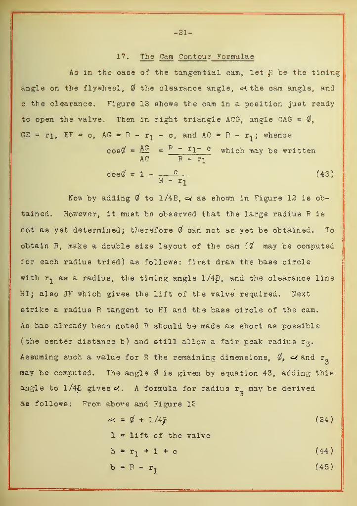
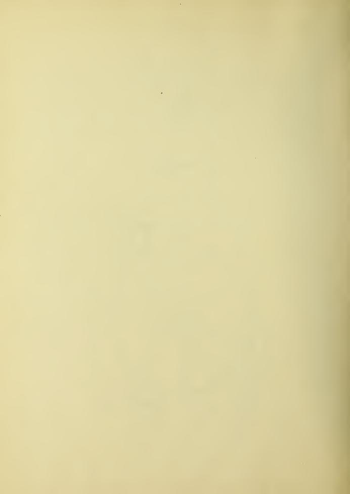
17. The Cam Contour formulae
As in the case of the tangential cam, let f be the timing
angle on the flywheel, 4 the clearance angle, ^ the cam angle, and
c the clearance. figure 13 shows the cam in a position just ready
to open the valve. Then in right triangle ACG, angle CAG = 0f,
GE = ri, EF = c, AG R - - o, and AC = P - r-,; whence
tained. However, it must be observed that the large radius P is
not as yet determined; therefore 4 can not as yet be obtained. To
obtain P, make a double size layout of the cam (# may be computed
for each radius tried) as follows: first draw the base circle
with r^ as a radius, the timing angle l/4£, and the clearance line
HI; also JF which gives the lift of the valve required. Next
strike a radius R tangent to HI and the base circle of the cam.
As has already been noted P should be made as short as possible
(the center distance b) and still allow a fair peak radius r 3 .
Assuming such a value for P the remaining dimensions, <=-< and ro
may be computed. The angle flf is given by equation 43, adding this
angle to l/4£ gives A formula for radius r mav be derived3
as follows: From above and Figure 12
4 + 1/4J (24)
1 lift of the valve
h rx + 1 + c (44)
b P - r1
(45)
-22-
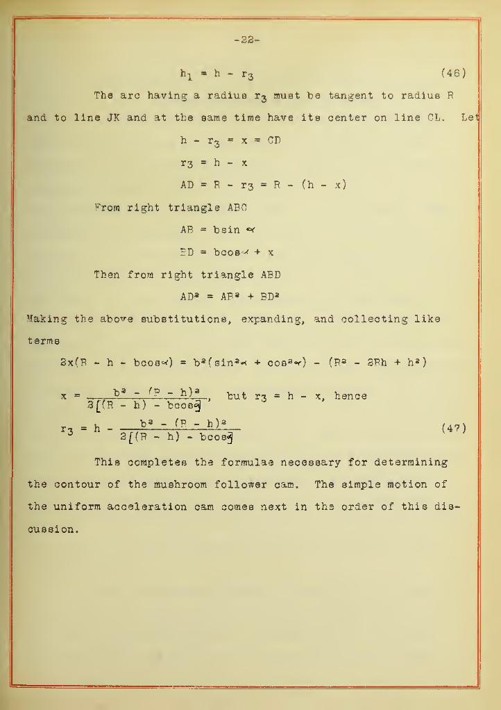
h 1 » h - r3 (46)
The arc having a radius r3 must be tangent to radius R
and to line JK and at the same time have its center on line CL. Let
h - r3
- x * CD
r3 h - x
AD = R - r 3 = R - (h - x)
vrora right triangle ABO
AE = b sin «*
PD = bcos^ + x
Then from right triangle ADD
AD3 = AR 3 + BD3
Making the above substitutions, expanding, and collecting like
terms
2x(P - h - bcos-0 * b 3 (sin 3 * + cos 3^) - (P 3 - 2Rh + h 3)
x = — b 3 - fP - h) 3but r3 = h - x, hence
3[fP. - fa) - bcoe^°
r 3= h . ' (B - h) 3
(47)3 2((R - fa) - bcos^J
This completes the formulae necessary for determining
the contour of the mushroom follower cam. The simple motion of
the uniform acceleration cam comes next in the order of this dis-
cussion.
-23-
f!HAPTED III. THE UHITORV ACCFT,EPAT ION CAM.
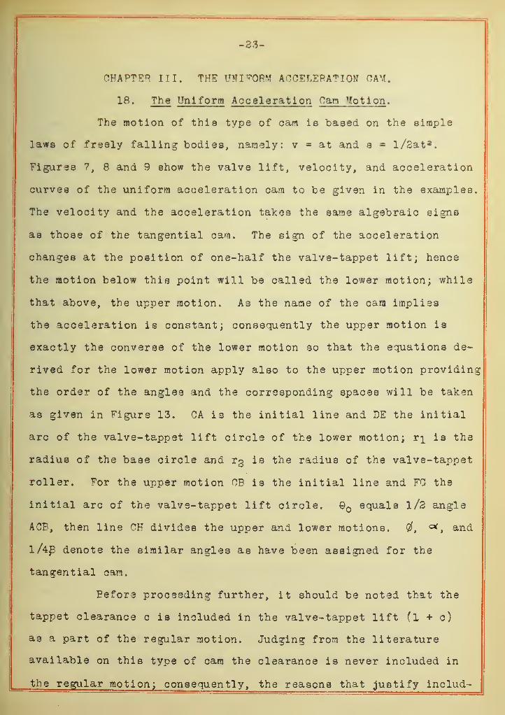
18. The Uniform Acceleration Can Motion.
The motion of this type of earn is "based on the simple
laws of freely falling bodies, namely: v = at and s = l/2at a.
Figures 7, 8 and 9 show the valve lift, velocity, and acceleration
curves of the uniform acceleration cam to be given in the examples.
The velocity and the acceleration takes the same algebraic signs
as those of the tangential cam. The sign of the acceleration
changes at the position of one-half the valve-tappet lift; hence
the motion below this point will be called the lower motion; while
that above, the upper motion. As the name of the cam implies
the acceleration is constant; consequently the upper motion is
exactly the converse of the lower motion so that the equations de-
rived for the lower motion apply also to the upper motion providing
the order of the angles and the corresponding spaces will be taken
as given in Figure 13. CA is the initial line and DE the initial
arc of the valve-tappet lift circle of the lower motion; r]_ is the
radius of the base circle and t% is the radius of the valve-tappet
roller. F r the upper motion OB is the initial line and FO the
initial arc of the valve-tappet lift circle. Q equals l/2 angle
ACP, then line CH divides the upper and lower motions. Cf, , and
l/4£ denote the similar angles as have been assigned for the
tangential cam.
Pefore proceeding further, it should be noted that the
tappet clearance c is included in the valve-tappet lift (l + c)
as a part of the regular motion. Judging from the literature
available on this type of cam the clearance is never included in
the regular motion; consequently, the reasons that justify includ-
-24-
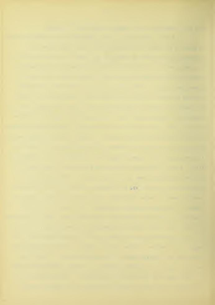
ing the clearance in the regular motion will "be given.
In the first place if the clearance is not added as above
it must be provided for by some other means aside from the
regular uniform motion in order to get down to the base circle of
the car contour. Of course the intention when not including the
clearance is to obtain a zero valve velocity when the valve is
opened and closed. This intention would be all well and good if
it were possible to keep the theoretical clearance at all times.
In regards to a cam in actual use one may say with reason that the
tappet will almost never have the theoretical clearance intended
for it. Even with a precise adjustment the clearance would change
with the temperature of the motor. In fact, these variable factors
are the sole cause of a clearance being necessary. Mot only is
it obvious why the clearance should be included in the regular mo-
tion; it also does away with any complications in the contour of
the cam in getting down to the base circle. This point will be
appreciated by those who make master cams used for the reproduc-
tion of cams in large quantities. vet this is not all that is in
favor of the regular motion throughout the contour of the cam. The
clearance angle gives almost the same additional angle to the angle
of full lift (ICB) without increasing the acceleration. Converse-
ly, the acceleration can be made less if the additional full lift
angle is not wanted. These various reasons justify including the
clearance as a regular part of the uniform motion. Especially
is this true of the present tendency to assign clearance as small
as 0.004 inch for " T,n and n T n head motors. The formulae for the
cam motion will now be derived in terms of the camshaft speed.
-25-
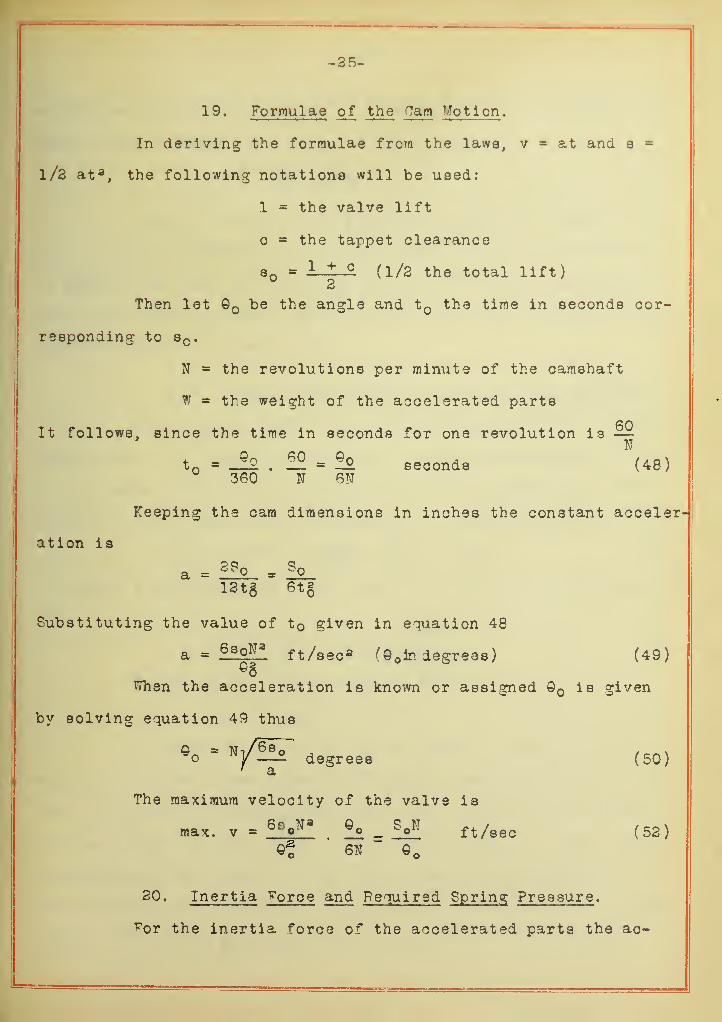
19. Formulae of the Cam Mo tion .
In deriving the formulae from the laws, v = at and s =
l/3 at a, the following notations will be used:
1 = the valve lift
= the tappet clearance
8 - 1 + (1/3 the total lift)2
Then let o be the angle and t the time in seconds cor-
responding to sc .
N = the revolutions per minute of the camshaft
W » the weight of the accelerated parts
60It follows, since the time in seconds for one revolution is —
Nt c = _£o
. 22. = ££ seconds (48)360 N 6N
Keeping the cam dimensions in inches the constant acceler
ation is
a = - ^0
12t§ 6tg
Substituting the value of t given in equation 48
a = ft/sec* (Q ir. degrees ) (49)
When the acceleration is known or assigned is given
by solving equation 49 thus
© = dsgrees (5Q)' a
The maximum velocity of the valve is
max. v ~ 6s oNa
?£ =M ft/sec (52)
20. Inertia ^orce and Required Spring Pressure .
For the inertia force of the accelerated parts the ac-
-36-
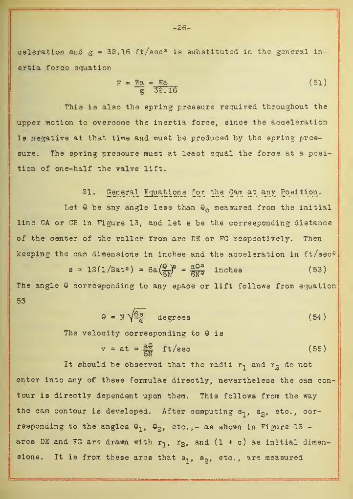
oeleration and g = 33.16 ft/esc 3 is substituted in the general in-
ertia force equation
F = Fa = Fa (51)g 32.16
This is also the spring pressure required throughout the
upper motion to overcome the inertia force, since the acceleration
is negative at that time and must be produced by the spring pres-
sure. The spring pressure must at least equal the force at a posi-
tion of one-half the valve lift.
31. General Equations for the Cam at any Position .
Let be any angle less than Q measured from the initial
line CA or CE in figure 13, and let s be the corresponding distance
of the center of the roller from arc BE or FG respectively. Then
keeping the cam dimensions in inches and the acceleration in ft/sec 2
s = 13(l/3at2) = Sa^)8 = ||£ inches (53)
The angle 9 corresponding to any space or lift follows from equation
53
Q = N^if^ degrees (54)
The velocity corresponding to © is
v = at = || ft/sec (55)
It should be observed that the radii r^ and t% do not
enter into any off" these formulae directly, nevertheless the cam con-
tour is directly dependent upon them. This follows from the way
the cam contour is developed. After computing s^, s2 , etc., cor-
responding to the angles 0^, ©3, etc.,- as shown in Figure 13 -
arcs DE and FG are drawn with r^ r2 , and (1 + c) as initial dimen-
sions. It is from these arcs that s^, Sg, etc., are measured
-87-
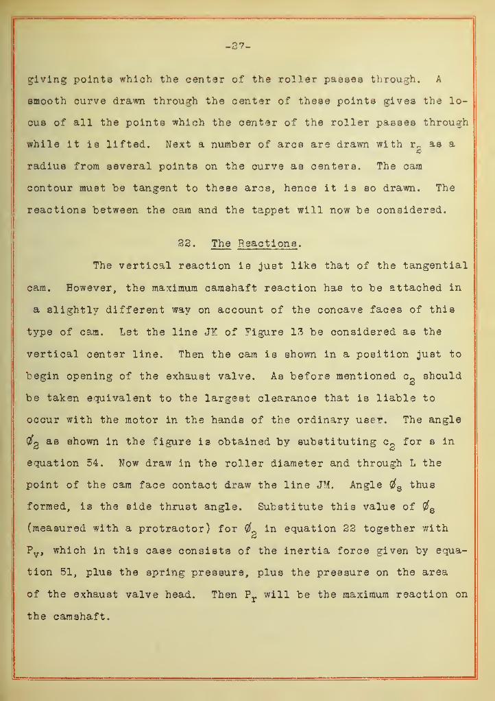
giving points which the center of the roller passes through. A
smooth curve drawn through the center of these points gives the lo-
cus of all the points which the center of the roller passes through
while it is lifted. Next a number of arcs are drawn with r^ as a3
radius from several points on the curve as centers. The cam
contour must be tangent to these arcs, hence it is so drawn. The
reactions between the cam and the tappet will now be considered.
33. The Reactions .
The vertical reaction is just like that of the tangential
cam. However, the maximum camshaft reaction has to be attached in
a slightly different way on account of the concave faces of this
type of cam. Let the line JT of Figure 13 be considered as the
vertical center line. Then the cam is shown in a position just to
begin opening of the exhaust valve. As before mentioned c^ should
be taken equivalent to the largest clearance that is liable to
occur with the motor in the hands of the ordinary user. The angle
Qfp as shown in the figure is obtained by substituting cn for s in— &
equation 54. Now draw in the roller diameter and through L the
point of the cam face contact draw the line JM. Angle $B thus
formed, is the side thrust angle. Substitute this value of 8
(measured with a protractor) for # in equation 22 together with
Pv , which in this case consists of the inertia force given by equa-
tion 51, plus the spring pressure, plus the pressure on the area
of the exhaust valve head. Then Prwill be the maximum reaction on
the camshaft.

-38-
23. Relativ e Noise Fac tor and Senal tlvene sa of theValve Timing .
In concluding the theory of the motion of the cams, an
effort will be made to call attention to the relative noise caused
by the different cam motions; and to the relative sensitiveness
of the valve timing. However, in considering the former topic
it will be given only as a suggestion. On the other hand, it is
not necessary to uphold the contention that a reliable noise factor
would be of no small importance in comparing contemplated valve
actions; since every designer knows that quietness of the valve
action is very important if the approval of the buying public is to
be gained. The noise factor to be assumed is based on the relation
expressed for the momentum of a body having a given velocity,
namely: the product of the mass by the velocity. The mass of the
valve being the same, whatever type of cam is used, will be omitted
as it is a relative factor that is wanted. As to the mass of the
tappet it will also be omitted since its reaction is towards the
cam (in the lower motion). Then it follows that the impact of the
motion is at the end of the valve stem when the valve opens and
at the valve seat when it closes. Evidently the valve spring pres-
sure and the velocity of the valve on closing and opening are the
two main factors causing the relative noise of the cam motions.
From this fact it is assumed that under otherwise like conditions
the noise of each impact is proportional to the product of the
spring pressure and the velocity of the valve at that time. Ey
means of the equations already given the velocity may be computed
at the point of correct tappet clearance ^c); also at a point
T
-29-
which is in accord with the way the average motor users ar3 often
content to let a motor run,- say up to l/32 inch clearance (02).
The product of these velocities by the spring pressure, each taken
separately, may be compared with similar products in order to com-
pare the relative merits of each in regard to the least noise
produced. In connection with the above comparison, the relative
sensitiveness of the valve timing should be considered. This is
done by noting the value of the angle 0g which had to be computed
in determining the velocity at the point of l/32 inch clearance
(Cg). The number of degrees the timing is out, measured on the
flywheel, is 2(#2 - being the clearance angle for proper
adjustment. The relative sensitiveness of each valve timing corres
ponding to the different cams compared is exposed by comparing the
variations noted on the flywheel. The importance of this compari-
son is readily seen in the case where a quiet cam motion is gained
at the expense of an overly sensitive valve timing. The latter
factor is decidedly detrimental to the uniform performance of a
motor. Such timing not only gives a wide variation for a certain
careless adjustment, but as these adjustments will differ for each
cylinder it can be seen that the timing for each will also be at
variance with each other.

-30-
CHAPTEP IT. EXAMPLE8 TO ILLUSTRATE THEAPPLICATION OF THE THEOPY 0^ THE CAM MOTION
24. Conditions Assumed for Examples .
Three intake cams have been designed for the following
initial conditions:
Valve opens at 16° after upper dead center.
Valve closes at 40° after lower dead center.
. £ = (180° - 16°) + 40° = 204°
l/4£ = 51° one-half the timing angle of thecam.
Valve tappet clearance, c = .010 inch
In calculating the maximum reaction on the camshaft a
. inchesvalve having a diameter of 2 1/18, will be assumed to be operated.
The lower motion of the exhaust cam will be taken the same as the
intake cams. Since the valve head area is 3.6 fapprox. ) square
inches and the unit exhaust pressure may be taken at 50 lbs. per
square inch, it follows that 180 lbs. is the total exhaust pressure
on the valve. In each case this pressure will be added to the
inertia and spring pressure forces for the vertical reaction. The
speed of the camshaft will be taken as 1000 RPM.
The remaining initial conditions are slightly different
for each type of cam. First the tangential cam was designed and
its valve lift curve plotted. Then the mushroom follower cam was
designed to give approximately the same area under the valve lift
curve Figure 7 as that of the tangential cam, in order that each
of these two cams should give nearly identical results as far as
the volumetric efficiency of the motor would be concerned. This
was accompanied by giving less valve lift to the mushroom follower
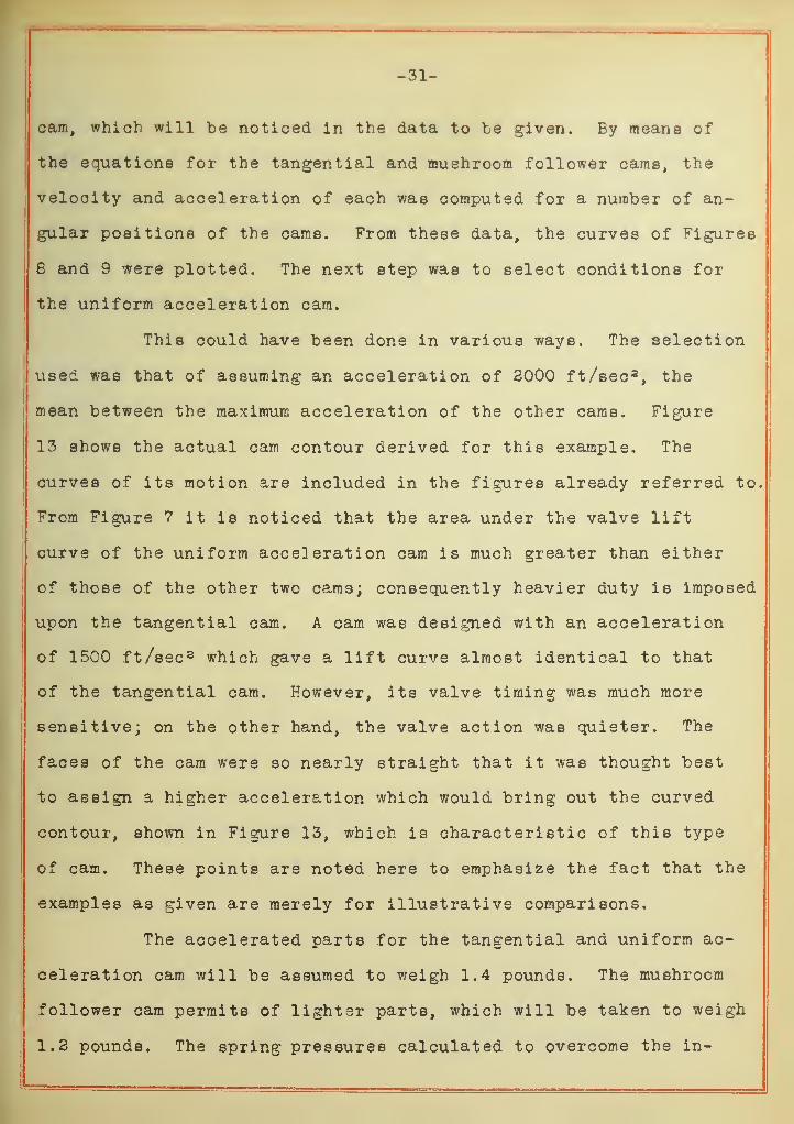
-31-
cam, which will be noticed in the data to be given. By means of
the equations for the tangential and muehroom follower cams, the
velocity and acceleration of each was computed for a number of an-
gular positions of the came. From these data, the curves of Figures
8 and 9 were plotted. The next step was to select conditions for
the uniform acceleration cam.
This could have been done in various ways. The selection
i used was that of assuming an acceleration of 2000 ft/sec 2, the
mean between the maximum acceleration of the other cams. Figure
13 shows the actual cam contour derived for this example. The
curves of its motion are included in the figures already referred to.
From Figure 7 it is noticed that the area under the valve lift
curve of the uniform acceleration cam is much greater than either
of those of the other two cams; consequently heavier duty is imposed
upon the tangential cam. A cam was designed with an acceleration
of 15C0 ft/sec 2 which gave a lift curve almost identical to that
of the tangential cam. However, its valve timing was much more
sensitive; on the other hand, the valve action was quieter. The
faces of the cam were so nearly straight that it was thought best
to assign a higher acceleration which would bring out the curved
contour, shown in Figure 13, which is characteristic of this type
of cam. These points are noted here to emphasize the fact that the
examples as given are merely for illustrative comparisons.
The accelerated parts for the tangential and uniform ac-
celeration cam will be assumed to weigh 1.4 pounds. The mushroom
follower cam permits of lighter parts, which will be taken to weigh
1.2 pounds. The spring pressures calculated to overcome the in-
-32-
ertia forces at full valve lift (except the uniform acceleration
cam, one-half the valve lift) will be assumed for these examples
to be correct for the closed position of the valve. That is, the
building up of the spring compression is to take care of the addi-
tional pressure required to overcome the conditions as mentioned
in the discussion of the tangential cam motion.
The same notation used in the theory of the motion will
be used as far as possible. Each type of cam will be treated in
order, as follows:
The Tangential Cam.
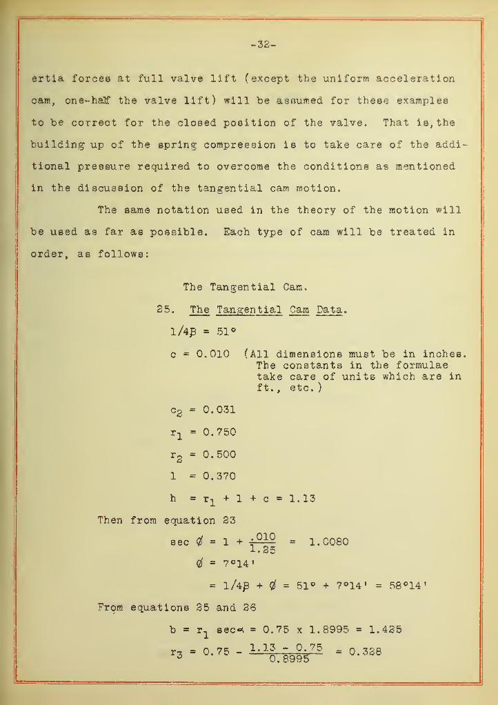
25. The Tangential Cam Data .
1/43 = 51°
c 0.010 (All dimensions must be in inches.The constants in the formulaetake care of units which are inft. , etc. )
c2 = 0.031
rx
= 0.750
r2
= 0.500
1 = 0.370
h = r1
+ 1 + c = 1.13
Then from equation 23
sec = 1 + ^£ = 1.00801. 25
$ = 7°14 !
= l/4£ + = 51° + 7°14' = 58°14'
From equations 25 and 26
b = r1
sec* = 0.75 x 1.8995 = 1.425
r-i = 0.75 - 1.13 - 0.75 = q.3283 0.8995

-33-
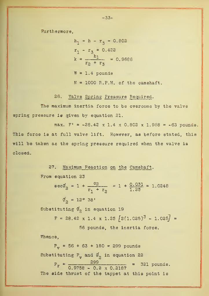
Furthermore,
h1
= h - r3
0.802
r- - r- 0.432
hik = ±— - 0.9686
r2 + r 3
W = 1.4 pounds
N = 1000 R.P.M. of the camshaft.
26. Valve Spring Pressure Required .
The maximum inertia foroe to be overcome by the valve
spring pressure ie given by equation 21.
max. F ' = -28.42 x 1.4 x 0.802 x 1.968 = -63 pounds.
This force is at full valve lift. However, as before stated, this
will be taken as the spring pressure required when the valve is
closed.
27. Maximum Peaction on the Camshaft .
From equation 23
sec^L = 1 + —— = 1 + °' 031 = 1.02482 r
x+ r
21.25
$z
= 12° 38'
Substituting in equation 19
F - 28.42 x 1.4 x 1.25 [2(1. 025) 3 - 1.035J=
56 pounds, the inertia force.
Whence,
Pv= 56 + 63 + 180 = 299 pounds
Substituting Py
and ^ in equation 22
Pr = — = 321 pounds.r 0.9758 - 0.2 x 0.2187The side thrust of the tappet at this point is

-34-
Ps
= P r sin02 = 321 x 0.2187 = 70 pounds.
However, the side thrust at the upper bound of the lower
motion may be greater.
28. Maximum Side Thrust after the Valve Is Open .
This side thrust will be calculated as an illustration
to show the use of the formulae for cases not included in the
discussion. The side thrust at the upper bound of the lower motion
may be obtained as follows:
From equation (9)
tan0o = ,
4 - 33 tan 58°14' = 0.5453c 1.35Q = 38°36»
Substituting QQ in equation 19 gives the inertia force
F = 28.42 x 1.4 x 1.25 [2(1. 139) 3 - 1.139] =
91 pounds.
Assuming the spring pressure builds up 8 pounds at this point, then
the vertical reaction P^. = 91 + 63 + 8 = 162 pounds. Now by acting
figures 2 and 3, and the first part of equation 22, the reaction
on the cam will be computed. Since the velocity of the tappet is
low (6.78 ft/min) the coefficient of kinetic friction (p) will be
taken as .06. SubstitutingQ
for 2 ,Pv ' for Pv , and 0.06 for
in equation 22
Pi = — 1§2 = i9i pounds.r 0.87798 - 0.06 x 0.47869
Then the side thrust
Ps
= P^ sinG = 191 x 0.47869 = 91 pounds.
29. Valve Action Noise Factors . (N.F.
)
Substituting $ for in equation 7

v1
= 8.73 x 1.25 tan 7°14 f sec 7°14» = 1.39 ft/sec
and for (2fg
v2
= 8.73 x 1.25 tan 12038 1 sec 13°38' = 2.53 ft/sec
Then
(N. v.)i V} x 63 = 88 (For proper tappet adjust-
ment )
( N . F .
)
2= v
2x 63 = 159 (For l/33 inch tappet ad-
justment )
These relative factors are to be compared with those of the other
cams. The larger the factor, the greater is the corresponding
noise. It is of interest to note that the noise factor is about
twice as great at a clearance adjustment of l/33 inch, as it is
at the proper adjustment. This fact is a clue to the reason why
the theoretical clearance should be made as small as possible.
30. Sensitiveness of the Valve Timing .
This measured on the flywheel is 2((#2
- 0) - 2(13°38 l
7°14') = 10°48 f the amount the timing is out at a slack tappet
adjustment of l/3S inch.
The Mushroom Follower Cam.
The Mushroom Follower Cam Data .
l/4£ = 51°
c = 0.010
c2= 0.031
1 = 0.340
h=r1+l+c= 1.33
P = 3.00
-36-
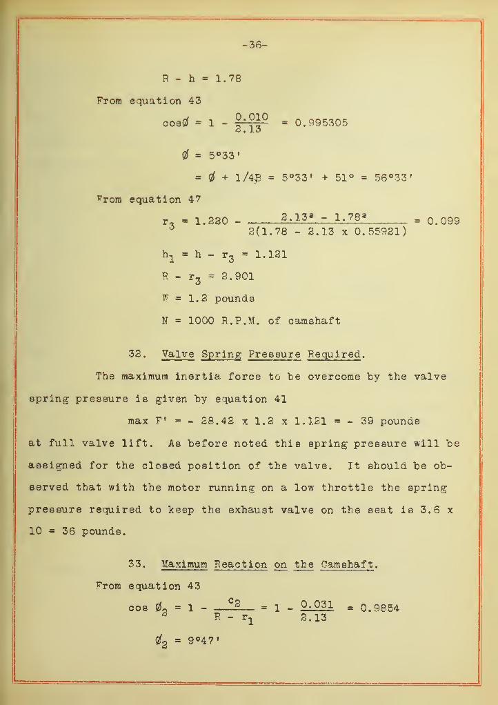
R - h = 1.78
From equation 43
costf = 1 - = °* 995305
4 5°33'
= 4 + l/4£ = 5°33' + 51° = 56°33«
^rora equation 47
r, = 1.230 - 2.13 8 - 1.78 8 = 0.0996 2(1.78 - 2.13 x 0.55921)
ha
= h - r3
= 1.121
R - r3
= 2.901
W = 1.2 pounds
N = 1000 R.P.M. of camshaft
32. Valve Spring Pressure Required .
The maximum inertia force to be overcome by the valve
spring pressure is given by equation 41
max F 1 = - 28.42 x 1.2 x 1.131 = - 39 pounds
at full valve lift. As before noted this spring pressure will be
assigned for the closed position of the valve. It should be ob-
served that with the motor running on a low throttle the spring
pressure required to keep the exhaust valve on the seat is 3.6 x
10 = 36 pounds.
33. Maximum Reaction on the Camshaft .
From equation 43
cos 4 1 - ——— = 1 - °- 031 = 0.9854* R - r
x 2.13
4 = 90471
-37-
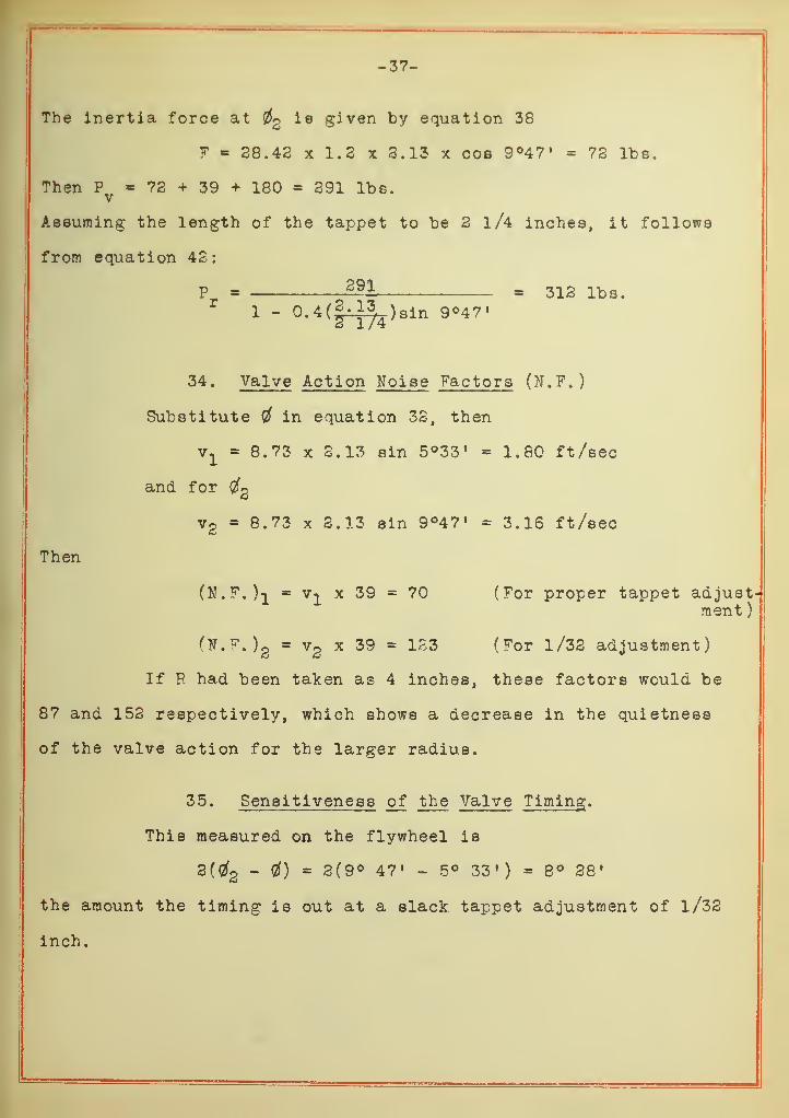
Th e inertia force at 2 ie given by equation 38
F = 28.42 x 1.2 x 2.13 x cos 9°47' - 72 lbs.
Then Py
= 72 + 39 + 180 = 291 lbs.
Assuming the length of the tappet to be 2 l/4 inches, it follows
from equation 42:
P = 292 . 312 lbs.1 - 0.4(|-^4
)sin 9°47»
34. Valve Action Noise Factors (N.F.)
Substitute # in equation 32, then
v1
= 8.73 x 2.13 sin 5°33» = 1.80 ft/sec
and for $2
v2 = 8.73 x 2.13 sin 9°47» = 3.16 ft/sec
Then
(N.F.)} = V]_ x 39 = 70 (For proper tappet adjust-ment )
(tf.F.)g = v2
x 39 - 123 (For l/32 adjustment)
If R had been taken as 4 inches, these factors would be
87 and 152 respectively, which shows a decrease in the quietness
of the valve action for the larger radius.
35. Sensitiveness of the Valve Timing .
This measured on the flywheel is
3(tf2- 0) = 3(9° 47» - 5° 33') = 8° 28»
the amount the timing is out at a slack tappet adjustment of l/32
inch.

-38-
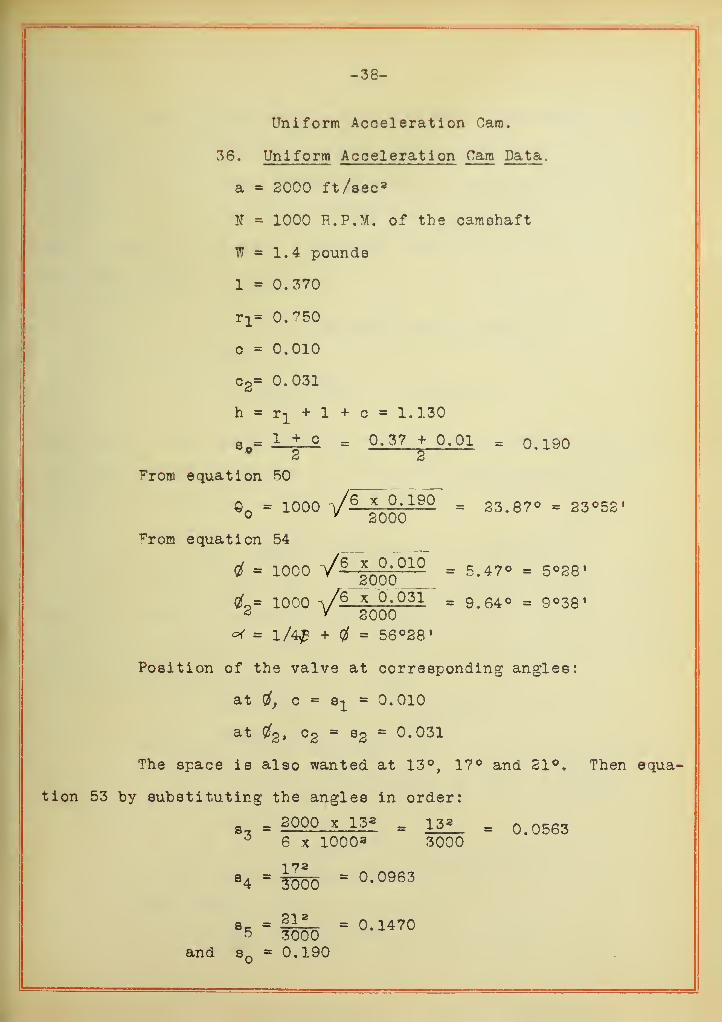
Uniform Acceleration Cam.
36. Uniform Acceleration Cam Data ,
a = 2000 ft/sec a
N = 1000 R.P.M. of the camshaft
W = 1.4 pounds
1 - 0.370
Ti= 0.?50
c = 0.010
03= 0.031
h=r1 +l+c= 1.130
a = 2_±__2. = 0.37 + 0.01 = 0.190p2 2
^rom equation 50
©n = 1000 V 6 X °- 190 = 23.87° = 23°52" 2000
rrom equation 54
= 1000 /6
3 qq010 = ^.47° = 5°28'
1000 V6 x Q-OjT * 9.64° = 9°38»2 / 2000
<* = l/4£ + fif = 56°28 !
Position of the valve at corresponding angles:
at tf, c e1
- 0.010
at $2> c2= s2 = 0.031
The space is also wanted at 13°, 17° and 21°. Then equa-
tion 53 by substituting the angles in order:
= 2000 x 13* _ 13a_ = 0>056366 x 1000 a 3000
84 = = °- 0963
Se. = §1L- = 0.14705 3000
and s 0.190
-39-
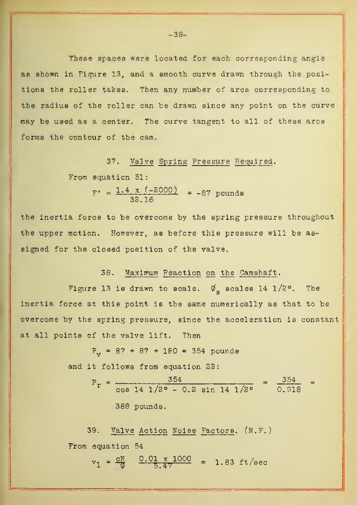
These spaces were located for each corresponding angle
as shown in Figure 13, and a smooth curve drawn through the posi-
tions the roller takes. Then any number of arcs corresponding to
the radius of the roller can be drawn since any point on the curve
may be used as a center. The curve tangent to all of these arcs
forms the contour of the cam.
37. Valve Spring Pressure Required .
From equation 51:
F' = I-* * f-S000,) = .8? pounds33.16
the inertia force to be overcome by the spring pressure throughout
the upper motion. However, as before this pressure will be as-
signed for the closed position of the valve.
38. Maximum Feaction on the Camshaft ,
figure 13 is drawn to scale. $&scales 14 1/2°. The
inertia force at this point is the same numerically as that to be
overcome by the spring pressure, since the acceleration is constant
at all points of the valve lift. Then
?v
= 87 + 8? + 180 = 354 pounds
and it follows from equation 22:
p = 354 _ 354 =r
cos 14 1/3° - 0.2 sin 14 l/2° 0.918
388 pounds.
39. Valve Action Noise Factors . (N.F.)
From equation 54
Vj = ON 0.01^1000 = i.83 ft/eeo
-40-
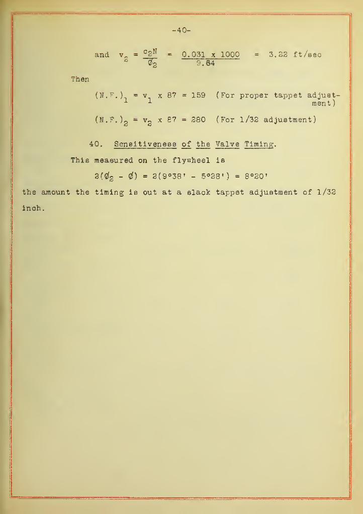
and vfi
= C2N = 0.031 x 1000 = 3.23 ft/secc OS
Then
(N. r .) = v x 87 = 159 (For proper tappet adjust1 1 merit)
(N.F.)2
= v2
x 87 = 380 (For l/32 adjustment)
40. Sensitiveness of the Valve Timing .
This measured on the flywheel is
3(0(3 - Gf) * 2(9°38' - 5°28M 8°20*
the amount the timing is out at a slack tappet adjustment of 1/32
inch.

-41-
Results and Conclusions.
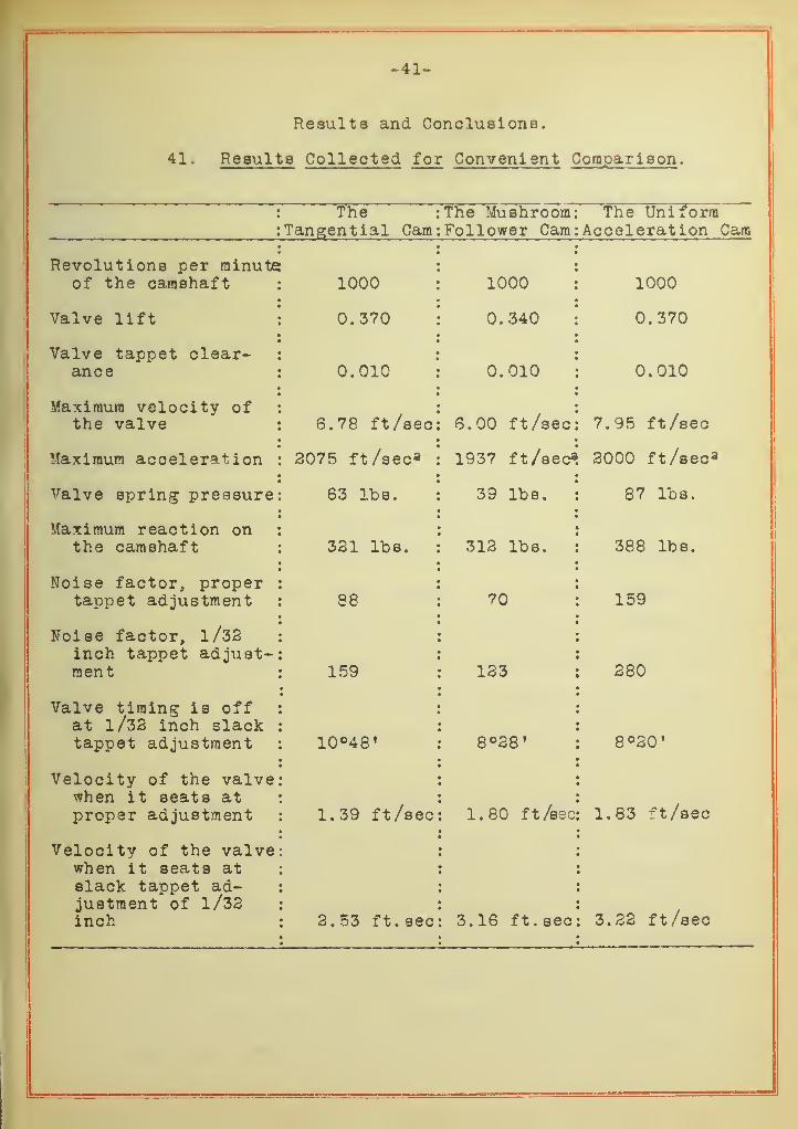
41. Results Collected for Convenient Comparison .
The :
Tangential Cam:The Mushroom:Follower Cam:
The UniformAcceleration Cam
Revolutions per minuteof the camshaft : 1000 : 1000 i 1000
Valve lift : 0.370 : 0.340 : 0.370
Valve tappet clear- :
ance : 0.010 « 0.010 \ 0.010
Maximum velocity of :
the valve ; 6.78 ft/sec: 6.00 ft/sec: 7.95 ft/sec
Maximum acceleration ;2075 ft/sec* : 1937 ft/sec^ 2000 ft /see 3
Valve spring pressure: 63 lbs. : 39 lbs. j 87 lbs.
Maximum reaction on ;
the camshaft : 321 lbs. : 312 lbs. : 388 lbs.
Noise factor, propertappet adjustment ; 88 : 70 j 159
Noise factor, 1/32inch tappet adjust-ment :
: 159 : 123 ; :280
Valve timing is offat l/32 inch slack
, O (JO 8°20'
Velocity of the valvewhen it seats atproper adjustment : 1.39 ft/sec : 1.80 ft /sec ; 1.83 ft /sec
Velocity of the valvewhen it seats atslack tappet ad-justment of l/32inch : 2.53 ft.sec : 3.16 ft.sec : 3.22 ft/sec
-43-
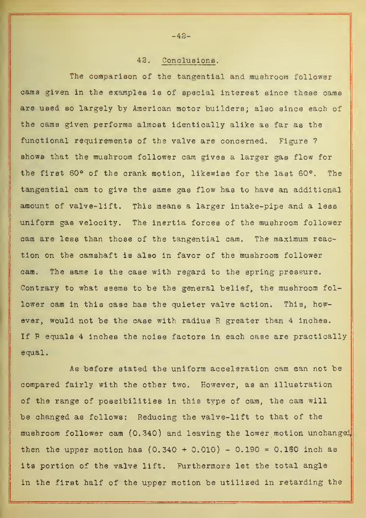
42. Conclusions .
The comparison of the tangential and mushroom follower
cams given in the examples is of special interest since these cams
are used so largely "by American motor builders; also since each of
the cams given performs almost identically alike as far as the
functional requirements of the valve are concerned. Figure 7
shows that the mushroom follower cam gives a larger gas flow for
the first 60° of the crank motion, likewise for the last 60°. The
tangential cam to give the same gas flow has to have an additional
amount of valve-lift. This means a larger intake-pipe and a less
uniform gas velocity. The inertia forces of the mushroom follower
cam are less than those of the tangential cam. The maximum reac-
tion on the camshaft is also in favor of the mushroom follower
cam. The same is the case with regard to the spring pressure.
Contrary to what seems to be the general belief, the mushroom fol-
lower cam in this case has the quieter valve action. This, how-
ever, would not be the case with radius R greater than 4 inches.
If F equals 4 inches the noise factors in each case are practically
equal
.
As before stated the uniform acceleration cam ean not be
compared fairly with the other two. However, as an illustration
of the range of possibilities in this type of cam, the cam will
be changed as follows: Reducing the valve-lift to that of the
mushroom follower cam (0,340) and leaving the lower motion unchanged,
then the upper motion has (0.340 + 0.010) - 0.190 = 0.160 inch as
its portion of the valve lift. Furthermore let the total angle
in the first half of the upper motion be utilized in retarding the
-43-
valve during the lift. Thi9 angle ia
c* - Qo
= (56 38 t - 33 5^•) = 32°36' = 32.6°
The negative acceleration corresponding to this angle follows from
equation 49
a = - 6 x 0.160 x 1000« = _903<3 ft /8eo a
32. 6 3
The lower acceleration of the upper motion reduces the spring
pressure. Substituting this acceleration in equation 51
F = - 1>4--^ ^?
3,:?- = -40 pounds.
3<o . In
This in turn reduces the maximum reaction on the camshaft. Now
Py- 87 + 40 + 180 = 307 pounds.
Then from equation 23 and since the lower motion was not changed
Pr = — . = 335 pounds.cos 14 1/3° -.2 sin 14 l/3°
The velocity of the lower motion has not changed, but the spring
pressure is now less; consequently the noise factors are also less.
They are: 40 x 1.83 = 73 and 40 x 3.23 139 for proper and slack
tappet adjustments repsectively. This cam as now given has a
slightly better valve lift curve than the mushroom follower cam.
In respect to the other factors (as far as their motions are con-
cerned) the two cams are almost identical.


r/G. 7.
-48-
-49-
iB
! ..
_ ,.
—
\— —j— J-—
j ,
-i
<
—1
1
1
1j
—
t—J 4- —
—
—
i
1
1
J—^^^^
1
4
1
i
SOOO
I so o
/OOO
O5<5(?
- SOO
-IOOO
-1500
-ZOOO
VA LVE-TRPPET ACCELERATION CURVE - N=ZOOO /=?./=>M.
TANGENTIAL CRM.— •—m—nusHRoon followelr caw.------UN IFORM ACCELERATION CAM.
r/G.9.


A.L.N.


t

ILLINOIS-UBBANA
3 0112 086831721