MATCHING OF SEPARATELY EXCITED DC MOTORS TO PHOTOVOLTAIC GENERATORS FOR MAXIMUM POWER OUTPUT
11
Solar Energy Vol. 63, No. 6, pp. 375–385, 1998 1998 Elsevier Science Ltd Pergamon PII: S0038–092X(98)00094–2 All rights reserved. Printed in Great Britain 0038-092X / 98 / $ - see front matter MATCHING OF SEPARATELY EXCITED DC MOTORS TO PHOTOVOLTAIC GENERATORS FOR MAXIMUM POWER OUTPUT ² MEHMET AKBABA , ISA QAMBER and ADEL KAMAL Department of Electrical Engineering, University of Bahrain, P.O. Box 33547, Isa Town, Bahrain Received 11 December 1997; revised version accepted 22 July 1998 Communicated by ROBERT HILL Abstract—This paper addresses the matching of separately excited dc motors to photovoltaic generators (PVG) for maximum power output. The dc motor is used to drive a centrifugal water pump. A PVG is a nonlinear device having insolation dependent I –V (current–voltage) characteristic, and hence a natural mismatch exists between the motor loads and the PVG. Therefore, considering the high initial cost of PVG, it is of vital importance to develop an appropriate matching process, to utilize PVG efficiently. In this article a procedure is developed to express the field current of the motor directly in terms of the maximum power point current and voltage of the PVG. It is shown that by adjusting the field current according to the developed relation, the motor is forced to follow the maximum power trajectory of the PVG, i.e. the input power of the motor is always equal to the maximum output power of the PVG at any available solar insolation. The effect of temperature on the I –V characteristic of the PVG is neglected at this stage. Finally a general expression is proposed relating the optimum field current directly to the available insolation level, which may be used as base for best matching. 1998 Elsevier Science Ltd. All rights reserved. 1. INTRODUCTION tory cells). Therefore the main interest of system designers concentrates on optimum matching Intensive effort are being made for developing between motor and PVG. But due to highly non- new processes for manufacturing the photovoltaic linear external characteristic ( I –V characteristic) cell and methods for enhancing their conversion of PVG and direct dependence on solar insolation. efficiency are currently being explored. These The problem of optimum matching is complex. efforts aim at reducing the cost per peak watt and Without taking corrective measures, natural mis- narrowing the gap between photovoltaic and match exists between the I –V characteristic of the conventional power sources for many applica- motor and the I –V characteristic of the PVG, and tions, such as water pumping systems, especially the equilibrium point on various load levels will in isolated areas. But improvements on the inter- not follow the maximum power trajectory of the actions between the cells and the rest of the PVG. Adding this to the low efficiency of the system will also yield rewards. PVG, without optimum match between PVG and The least expensive method of converting solar dc motor, system efficiency can drop to extremely energy into mechanical energy is direct interfac- low values, which makes the system uneconomi- ing of dc motors with photovoltaic generators cal. (PVG) without using storage batteries. One of the To overcome the drawback mentioned above, most suitable system to utilize solar energy is to two options are available: use PVG–dc motor to drive a water pump for (a) Careful selection of the dc motor and pump storing water for subsequent use in various forms such that they match the maximum power trajec- (Appelbaum, 1986; Appelbaum and Sarma, 1989; tory of the PVG as closely as possible (Appel- Saied, 1988; Saied and Jaboori, 1989; Zinger and baum, 1986; Appelbaum and Sarma, 1989; Saied, Braunstein, 1981). In such systems the most 1988; Saied and Jaboori, 1989; Saied and Hanafy, important concern is the relatively high cost of 1991). PVG, due to low cell efficiency (about 10% to (b) Use of a maximum power-point tracker 18% for most of the commercial cells available in (MPPT), which is an electronic control device the market and between 24% to 33% for labora- continuously matching the output characteristic of the PVG to the input characteristic of the dc ² motor. Author to whom correspondence should be addressed. Tel.: 1973 641819 or 1973 722127; fax: 1973 684844. A comprehensive study of directly coupled 375
-
Upload
independent -
Category
Documents
-
view
0 -
download
0
Transcript of MATCHING OF SEPARATELY EXCITED DC MOTORS TO PHOTOVOLTAIC GENERATORS FOR MAXIMUM POWER OUTPUT
Solar Energy Vol. 63, No. 6, pp. 375–385, 19981998 Elsevier Science Ltd
Pergamon PII: S0038 – 092X( 98 )00094 – 2 All rights reserved. Printed in Great Britain0038-092X/98/$ - see front matter
MATCHING OF SEPARATELY EXCITED DC MOTORS TO PHOTOVOLTAICGENERATORS FOR MAXIMUM POWER OUTPUT
†MEHMET AKBABA , ISA QAMBER and ADEL KAMALDepartment of Electrical Engineering, University of Bahrain, P.O. Box 33547, Isa Town, Bahrain
Received 11 December 1997; revised version accepted 22 July 1998
Communicated by ROBERT HILL
Abstract—This paper addresses the matching of separately excited dc motors to photovoltaic generators(PVG) for maximum power output. The dc motor is used to drive a centrifugal water pump. A PVG is anonlinear device having insolation dependent I–V (current–voltage) characteristic, and hence a naturalmismatch exists between the motor loads and the PVG. Therefore, considering the high initial cost of PVG, itis of vital importance to develop an appropriate matching process, to utilize PVG efficiently. In this article aprocedure is developed to express the field current of the motor directly in terms of the maximum power pointcurrent and voltage of the PVG. It is shown that by adjusting the field current according to the developedrelation, the motor is forced to follow the maximum power trajectory of the PVG, i.e. the input power of themotor is always equal to the maximum output power of the PVG at any available solar insolation. The effect oftemperature on the I–V characteristic of the PVG is neglected at this stage. Finally a general expression isproposed relating the optimum field current directly to the available insolation level, which may be used asbase for best matching. 1998 Elsevier Science Ltd. All rights reserved.
1. INTRODUCTION tory cells). Therefore the main interest of systemdesigners concentrates on optimum matching
Intensive effort are being made for developingbetween motor and PVG. But due to highly non-
new processes for manufacturing the photovoltaiclinear external characteristic (I–V characteristic)
cell and methods for enhancing their conversionof PVG and direct dependence on solar insolation.
efficiency are currently being explored. TheseThe problem of optimum matching is complex.
efforts aim at reducing the cost per peak watt andWithout taking corrective measures, natural mis-
narrowing the gap between photovoltaic andmatch exists between the I–V characteristic of the
conventional power sources for many applica-motor and the I–V characteristic of the PVG, and
tions, such as water pumping systems, especiallythe equilibrium point on various load levels will
in isolated areas. But improvements on the inter-not follow the maximum power trajectory of the
actions between the cells and the rest of thePVG. Adding this to the low efficiency of the
system will also yield rewards.PVG, without optimum match between PVG and
The least expensive method of converting solardc motor, system efficiency can drop to extremely
energy into mechanical energy is direct interfac-low values, which makes the system uneconomi-
ing of dc motors with photovoltaic generatorscal.
(PVG) without using storage batteries. One of theTo overcome the drawback mentioned above,
most suitable system to utilize solar energy is totwo options are available:
use PVG–dc motor to drive a water pump for(a) Careful selection of the dc motor and pump
storing water for subsequent use in various formssuch that they match the maximum power trajec-
(Appelbaum, 1986; Appelbaum and Sarma, 1989;tory of the PVG as closely as possible (Appel-
Saied, 1988; Saied and Jaboori, 1989; Zinger andbaum, 1986; Appelbaum and Sarma, 1989; Saied,
Braunstein, 1981). In such systems the most1988; Saied and Jaboori, 1989; Saied and Hanafy,
important concern is the relatively high cost of1991).
PVG, due to low cell efficiency (about 10% to(b) Use of a maximum power-point tracker
18% for most of the commercial cells available in(MPPT), which is an electronic control device
the market and between 24% to 33% for labora-continuously matching the output characteristic ofthe PVG to the input characteristic of the dc
† motor.Author to whom correspondence should be addressed. Tel.:1973 641819 or 1973 722127; fax: 1973 684844. A comprehensive study of directly coupled
375
376 M. Akbaba et al.
PVG–dc-motors-water pump systems is given by 2. I–V CHARACTERISTIC AND THE(Appelbaum, 1986 and Roger, 1979). It is con- MAXIMUM POWER TRAJECTORY OF PVGcluded that permanent magnet motor driving a
The external (I–V ) characteristic of a PVG hascentrifugal pump is the best candidate as it
been given by Appelbaum, 1986 and Al-possesses the best match between PVG and dc
ghuwainem, 1992, for example. The output cur-motor. Appelbaum and Sarma (1989) investigated
rent, I, is as follows:the performance of permanent magnet dc motors
I 5 I 2 I [exp(L(V2 R I)) 2 1] (1)driving different types of water pumps and po- ph o s
wered by a common PVG. Saied (1988) reportedand solving for the voltage, V, in terms of currenta work on matching of dc motors to PVG forI, we obtain:maximum daily gross mechanical energy. Some
proposals are made for modification in the dc 1]V5 2 R I 1 ln[(I 2 I 1 i ) /I ] (2)s ph o omotor parameters in order to achieve a better L
match. Maximum power point tracking iswhere I is the light generated current, I is theph oachieved in different ways, such as interchangingreverse saturation current, R is the series resist-sthe series parallel connections of solar modulesance, and L is the array constant.within the PVG as reported in Zinger and Brauns-
In Eq. (1) and Eq. (2), the internal shunttein (1981), or by using controlled dc–dc conver-resistance is neglected, as the internal shuntters either in the normal mode (Schoeman andresistance has negligible effect on the I–V charac-Van Wyk, 1982; Hanitsch and Hauk, 1985; Kich-teristic of PVG (Akbaba and Alattawi, 1995). Theak, 1979), or in step up mode (Alghuwainem,method proposed in this paper is based on maxi-1991, 1992). Alghuwainem (1992) investigatesmum power point voltage, V , and maximummaxthe determination of the optimal design parame-power point current, I of the PVG. Computa-max,ters of the system to match with the dc trans-tion of V or I from either Eq. (1) or Eq. (2)max maxformer ratio variation for obtaining maximumrequires lengthy iteration process, as they havegross annual mechanical energy.highly non-linear structure. To avoid this difficul-Although it is established in the literature thatty a recently published model for I–V characteris-permanent magnet dc motors are the best candi-tic (Akbaba and Alattawi, 1995), which in Ak-date for direct coupling the PVG–dc motor andbaba (1995) referred to as the ‘‘Akbaba model’’ iswater pump (Appelbaum, 1986 and Roger, 1979),used to compute the V and I directly withoutmax maxbut in the market still there are millions ofinvolving lengthy iterative calculations. Thisseparately excited (wound field winding) dcmodel is given as:motors. Therefore this current study is aimed at
2utilization of these motors in photovoltaic applica- I 5 (V 2V ) /(AV 1 BV2 C) (3)oction. For best match between PVG-separately
where V is the open circuit voltage of the PVG,ocexcited dc motor and water pump system anand A, B and C are the parameters of the modelintermediate circuit is needed between the motorand are computed as described in the Appendix.and PVG. Usually an MPTT device is used forUsing this model, the maximum power pointthis purpose. MPPT technique usually includes avoltage, V , is determined as (see later for Kmax 1micro-computer to control the dc–dc converterand K ):2which adds to the overall system cost. In this
]]]paper, therefore, a new approach is proposed for 2V 5 0.5(K 2 K 2 4K ) (4)œmax 1 1 2matching of dc motors to PVG for maximumoutput energy, by providing bases for design of an Having determined V the maximum powermaxalternative intermediate control circuit. The meth- point current, I , can be obtained as:maxod based on formulating the excitation current or 2I 5 (V 2V ) /(AV 1 BV 2 C) (5)max oc max max maxthe field winding flux linkages of a separatelyexcited dc motor such that the input I–V charac- and the maximum power of the PVG whichteristic of the dc motor follow the maximum produces the maximum power trajectory is ob-power trajectory of the PVG. By this means the tained as:best match is obtained between PVG and dc
P 5V I (6)max max maxmotor, and maximum daily gross mechanicalenergy is extracted from the PVG. The theoretical The constants K and K in Eq. (4) are given by:1 2results are demonstrated through various graphsshowing the validity of the proposed method. K 5 2A /(C 2 BV ) (7)1 oc
Matching of separately excited dc motors to photovoltaic generators for maximum power output 377
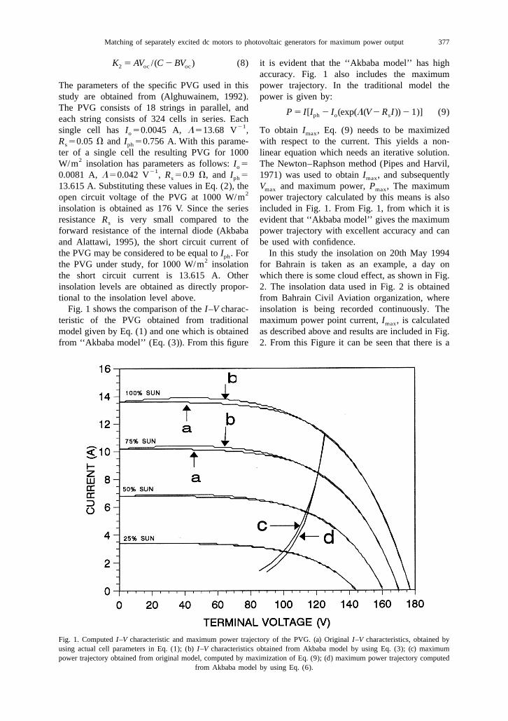
K 5 AV /(C 2 BV ) (8) it is evident that the ‘‘Akbaba model’’ has high2 oc oc
accuracy. Fig. 1 also includes the maximumThe parameters of the specific PVG used in this power trajectory. In the traditional model thestudy are obtained from (Alghuwainem, 1992). power is given by:The PVG consists of 18 strings in parallel, and P 5 I[I 2 I (exp(L(V2 R I)) 2 1)] (9)ph o seach string consists of 324 cells in series. Each
21single cell has I 50.0045 A, L513.68 V , To obtain I , Eq. (9) needs to be maximizedo max
R 50.05 V and I 50.756 A. With this parame- with respect to the current. This yields a non-s ph
ter of a single cell the resulting PVG for 1000 linear equation which needs an iterative solution.2W/m insolation has parameters as follows: I 5 The Newton–Raphson method (Pipes and Harvil,o
210.0081 A, L50.042 V , R 50.9 V, and I 5 1971) was used to obtain I , and subsequentlys ph max
13.615 A. Substituting these values in Eq. (2), the V and maximum power, P , The maximummax max2open circuit voltage of the PVG at 1000 W/m power trajectory calculated by this means is also
insolation is obtained as 176 V. Since the series included in Fig. 1. From Fig. 1, from which it isresistance R is very small compared to the evident that ‘‘Akbaba model’’ gives the maximums
forward resistance of the internal diode (Akbaba power trajectory with excellent accuracy and canand Alattawi, 1995), the short circuit current of be used with confidence.the PVG may be considered to be equal to I . For In this study the insolation on 20th May 1994ph
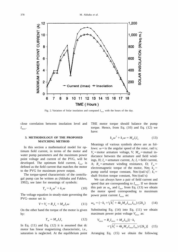
2the PVG under study, for 1000 W/m insolation for Bahrain is taken as an example, a day onthe short circuit current is 13.615 A. Other which there is some cloud effect, as shown in Fig.insolation levels are obtained as directly propor- 2. The insolation data used in Fig. 2 is obtainedtional to the insolation level above. from Bahrain Civil Aviation organization, where
Fig. 1 shows the comparison of the I–V charac- insolation is being recorded continuously. Theteristic of the PVG obtained from traditional maximum power point current, I , is calculatedmax
model given by Eq. (1) and one which is obtained as described above and results are included in Fig.from ‘‘Akbaba model’’ (Eq. (3)). From this figure 2. From this Figure it can be seen that there is a
Fig. 1. Computed I–V characteristic and maximum power trajectory of the PVG. (a) Original I–V characteristics, obtained byusing actual cell parameters in Eq. (1); (b) I–V characteristics obtained from Akbaba model by using Eq. (3); (c) maximumpower trajectory obtained from original model, computed by maximization of Eq. (9); (d) maximum power trajectory computed
from Akbaba model by using Eq. (6).
378 M. Akbaba et al.
Fig. 2. Variation of Solar insolation and computed I with the hours of the day.max
close correlation between insolation level and THE motor torque should balance the pumpI . torque. Hence, from Eq. (10) and Eq. (12) wemax
have:
23. METHODOLOGY OF THE PROPOSED k v 1 k v 5 M I I (13)p f af f a
MATCHING METHODMeanings of various symbols above are as fol-
In this section a mathematical model for op- lows: v 5is the angular speed of the rotor, rad /s;timum field current, in terms of the motor and V 5motor armature voltage, V; M 5mutual in-a afwater pump parameters and the maximum power ductance between the armature and field wind-point voltage and current of the PVG, will be ings, H; I 5armature current, A; I 5field current,a fdeveloped. The optimum field current, I , isfm A; R 5armature winding resistance, V; T 5a mdefined as the field current that matches the motor electromagnetic torque of the motor, Nm; k 5p
2to the PVG for maximum power output. pump useful torque constant, Nm/(rad /s) ; k 5fThe torque-speed characteristic of the centrifu- shaft friction torque constant, Nm/(rad /s)
gal pump can be written as (Akbaba and Fakhro, We can always have a pair of field current and1992), see later for meanings of symbols: speed that are corresponding to I . If we denotemax
2 this pair as v and I , from Eq. (13) we obtainm fmT 5 k v 1 k v (10)p p fthe motor speed corresponding to maximum
The voltage equation in steady-state governing the power point current I as:maxPVG–motor set is:
]]]]]2v 5 (2k 1 k 1 4k M I I ) /(2k ) (14)m f f p af max fm pœV5V 5 R I 1 M I v (11)a a a af f
Substituting Eq. (14) into Eq. (11) we obtainOn the other hand the torque of the motor is givenmaximum power point voltage V as:by: max
T 5 M I I (12) V 5 R I 1 M I [(2km af f a max a max af fm f
]]]]]2In Eq. (11) and Eq. (12) it is assumed that dc 1 k 1 4k M I I ) /(2k )] (15)f p af max fm pœmotor has linear magnetizing characteristic, i.e.,
Arranging Eq. (15) we obtain the followingsaturation is neglected. At the equilibrium point
Matching of separately excited dc motors to photovoltaic generators for maximum power output 379
equation for the field current corresponding to between the field and armature windings of themaximum power point: motor and maximum power point voltage and
current of the PVG. Also it can be seen from Eq.k (V 2 R I )f max a max3 (17) that V and M have much stronger effectmax af]]]]]I 2fm F 2 G on the optimum field current. V varies sig-M I maxaf max
nificantly with the cell temperature, but I is2 maxk (V 2 R I )p max a max less dependent on the cell temperature (Markvart,]]]]]I 2 5 0 (16)F Gfm 3M I 1994). On the other hand M is dependent on theaf max af
magnetic saturation. Therefore for accurate per-Eq. (16) gives the optimum field current that formance prediction, these effects must be in-matches the input power of the motor to the cluded in Eq. (17). Inclusion of these effects ismaximum power trajectory of the PVG. Solving under consideration by the authors and will beEq. (16) by applying the Cardano’s formula subject of a further publication.(Iyagawa and Kawada, 1968) we obtain: Substituting optimum field current, I , calcu-fm
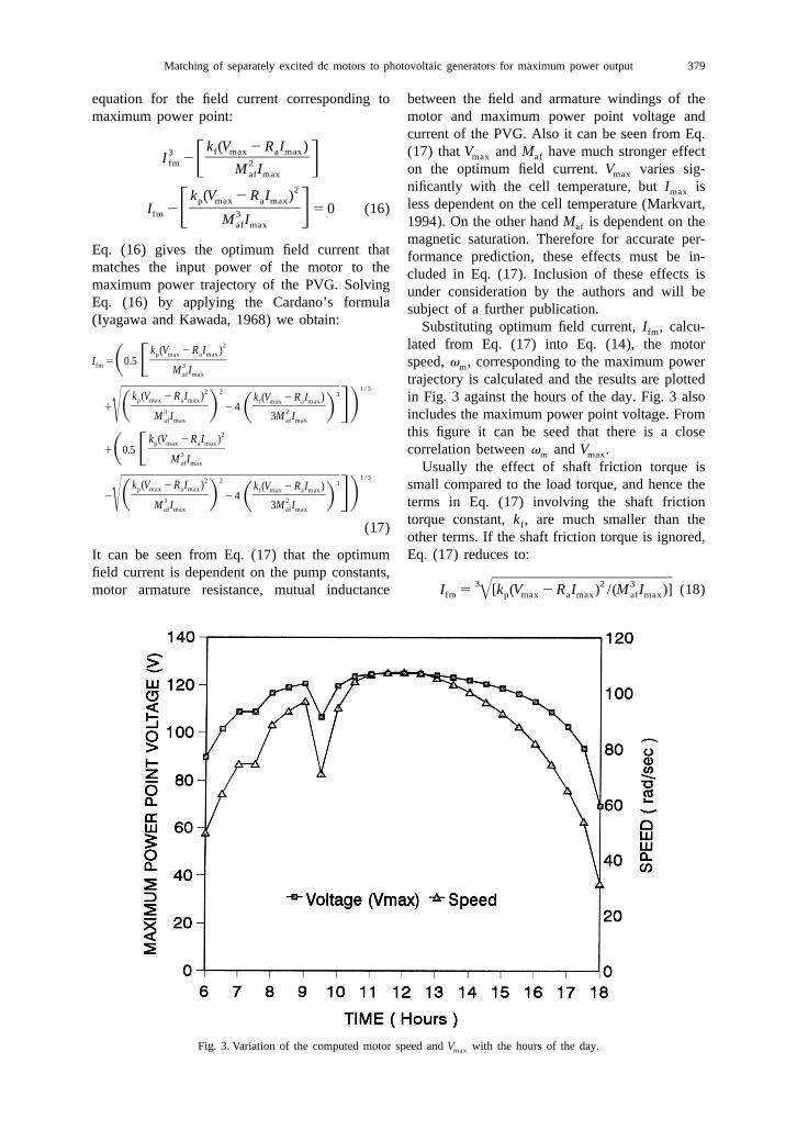
2 lated from Eq. (17) into Eq. (14), the motork (V 2 R I )p max a max]]]]I 5 0.5 speed, v , corresponding to the maximum powerS Ffm 3 mM Iaf max trajectory is calculated and the results are plotted
]]]]]]]]]] 1 / 32 2 3k (V 2 R I ) k (V 2 R I ) in Fig. 3 against the hours of the day. Fig. 3 alsop max a max f max a max]]]] ]]]]1 2 4 GDS D3 S 2 D includes the maximum power point voltage. FromM I 3M Iœ af max af max
this figure it can be seed that there is a close2k (V 2 R I )p max a max]]]]1 0.5 correlation between v and V .S F 3 m maxM Iaf max Usually the effect of shaft friction torque is
]]]]]]]]]] 1 / 32 2 3k (V 2 R I ) small compared to the load torque, and hence thek (V 2 R I )p max a max f max a max]]]] ]]]]2 2 4 GDS D3 S 2 D terms in Eq. (17) involving the shaft frictionM I 3M Iœ af max af max
torque constant, k , are much smaller than thef(17)other terms. If the shaft friction torque is ignored,Eq. (17) reduces to:It can be seen from Eq. (17) that the optimum
field current is dependent on the pump constants, ]]]]]]]]]3 2 3I 5 [k (V 2 R I ) /(M I )] (18)motor armature resistance, mutual inductance fm p max a max af maxœ
Fig. 3. Variation of the computed motor speed and V with the hours of the day.max
380 M. Akbaba et al.
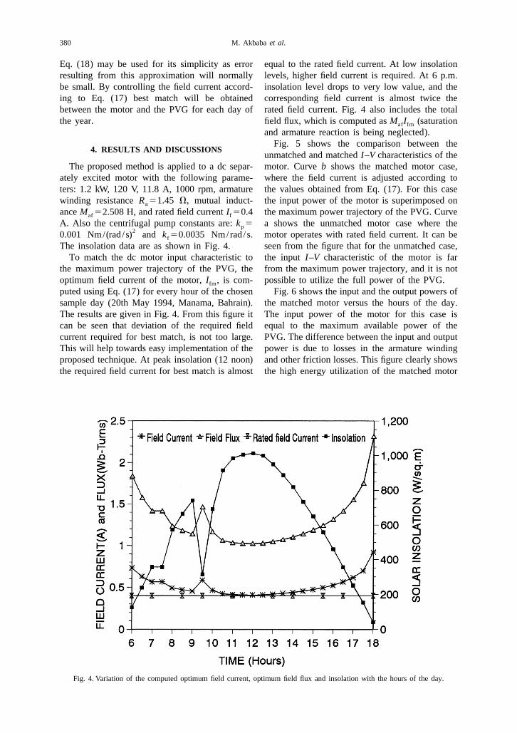
Eq. (18) may be used for its simplicity as error equal to the rated field current. At low insolationresulting from this approximation will normally levels, higher field current is required. At 6 p.m.be small. By controlling the field current accord- insolation level drops to very low value, and theing to Eq. (17) best match will be obtained corresponding field current is almost twice thebetween the motor and the PVG for each day of rated field current. Fig. 4 also includes the totalthe year. field flux, which is computed as M I (saturationaf fm
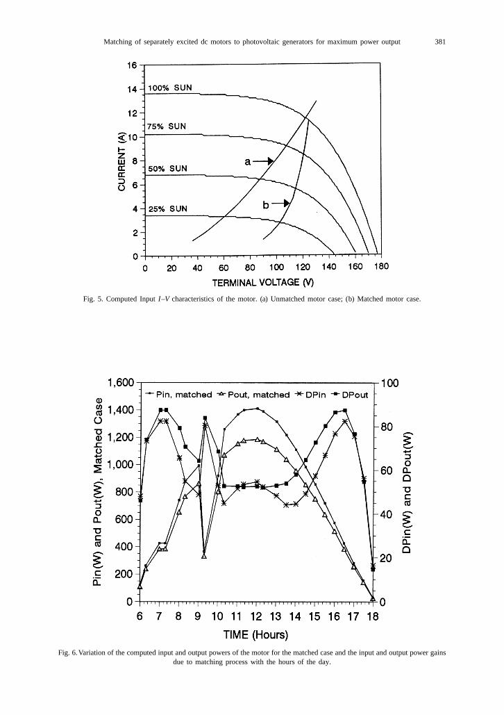
and armature reaction is being neglected).Fig. 5 shows the comparison between the
4. RESULTS AND DISCUSSIONSunmatched and matched I–V characteristics of the
The proposed method is applied to a dc separ- motor. Curve b shows the matched motor case,ately excited motor with the following parame- where the field current is adjusted according toters: 1.2 kW, 120 V, 11.8 A, 1000 rpm, armature the values obtained from Eq. (17). For this casewinding resistance R 51.45 V, mutual induct- the input power of the motor is superimposed ona
ance M 52.508 H, and rated field current I 50.4 the maximum power trajectory of the PVG. Curveaf f
A. Also the centrifugal pump constants are: k 5 a shows the unmatched motor case where thep20.001 Nm/(rad /s) and k 50.0035 Nm/rad/s. motor operates with rated field current. It can bef
The insolation data are as shown in Fig. 4. seen from the figure that for the unmatched case,To match the dc motor input characteristic to the input I–V characteristic of the motor is far
the maximum power trajectory of the PVG, the from the maximum power trajectory, and it is notoptimum field current of the motor, I , is com- possible to utilize the full power of the PVG.fm
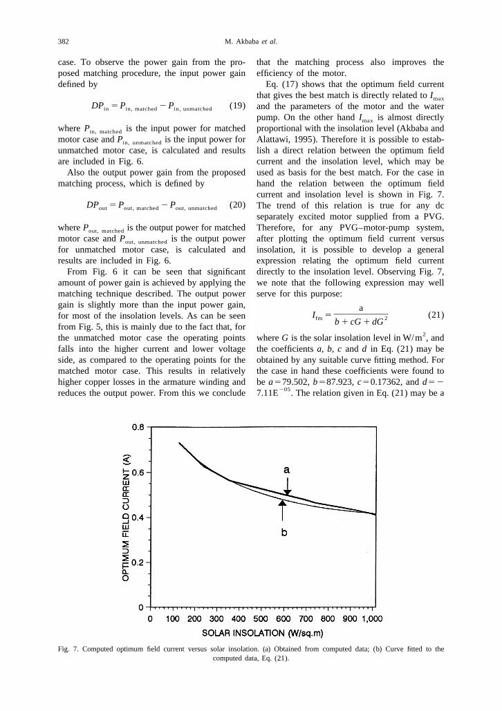
puted using Eq. (17) for every hour of the chosen Fig. 6 shows the input and the output powers ofsample day (20th May 1994, Manama, Bahrain). the matched motor versus the hours of the day.The results are given in Fig. 4. From this figure it The input power of the motor for this case iscan be seen that deviation of the required field equal to the maximum available power of thecurrent required for best match, is not too large. PVG. The difference between the input and outputThis will help towards easy implementation of the power is due to losses in the armature windingproposed technique. At peak insolation (12 noon) and other friction losses. This figure clearly showsthe required field current for best match is almost the high energy utilization of the matched motor
Fig. 4. Variation of the computed optimum field current, optimum field flux and insolation with the hours of the day.
Matching of separately excited dc motors to photovoltaic generators for maximum power output 381
Fig. 5. Computed Input I–V characteristics of the motor. (a) Unmatched motor case; (b) Matched motor case.
Fig. 6.Variation of the computed input and output powers of the motor for the matched case and the input and output power gainsdue to matching process with the hours of the day.
382 M. Akbaba et al.
case. To observe the power gain from the pro- that the matching process also improves theposed matching procedure, the input power gain efficiency of the motor.defined by Eq. (17) shows that the optimum field current
that gives the best match is directly related to Imax
DP 5 P 2 P (19) and the parameters of the motor and the waterin in, matched in, unmatched
pump. On the other hand I is almost directlymax
where P is the input power for matched proportional with the insolation level (Akbaba andin, matched
motor case and P is the input power for Alattawi, 1995). Therefore it is possible to estab-in, unmatched
unmatched motor case, is calculated and results lish a direct relation between the optimum fieldare included in Fig. 6. current and the insolation level, which may be
Also the output power gain from the proposed used as basis for the best match. For the case inmatching process, which is defined by hand the relation between the optimum field
current and insolation level is shown in Fig. 7.DP 5 P 2 P (20) The trend of this relation is true for any dcout out, matched out, unmatched
separately excited motor supplied from a PVG.where P is the output power for matched Therefore, for any PVG–motor-pump system,out, matched
motor case and P is the output power after plotting the optimum field current versusout, unmatched
for unmatched motor case, is calculated and insolation, it is possible to develop a generalresults are included in Fig. 6. expression relating the optimum field current
From Fig. 6 it can be seen that significant directly to the insolation level. Observing Fig. 7,amount of power gain is achieved by applying the we note that the following expression may wellmatching technique described. The output power serve for this purpose:gain is slightly more than the input power gain, a
]]]]I 5 (21)for most of the insolation levels. As can be seen fm 2b 1 cG 1 dGfrom Fig. 5, this is mainly due to the fact that, for2the unmatched motor case the operating points where G is the solar insolation level in W/m , and
falls into the higher current and lower voltage the coefficients a, b, c and d in Eq. (21) may beside, as compared to the operating points for the obtained by any suitable curve fitting method. Formatched motor case. This results in relatively the case in hand these coefficients were found tohigher copper losses in the armature winding and be a579.502, b587.923, c50.17362, and d52
205reduces the output power. From this we conclude 7.11E . The relation given in Eq. (21) may be a
Fig. 7. Computed optimum field current versus solar insolation. (a) Obtained from computed data; (b) Curve fitted to thecomputed data, Eq. (21).
Matching of separately excited dc motors to photovoltaic generators for maximum power output 383
very useful tool for designing the control circuit H and J5total inertia of the shaft, 50.086,2that matches dc motors to PVG for maximum kg.m .
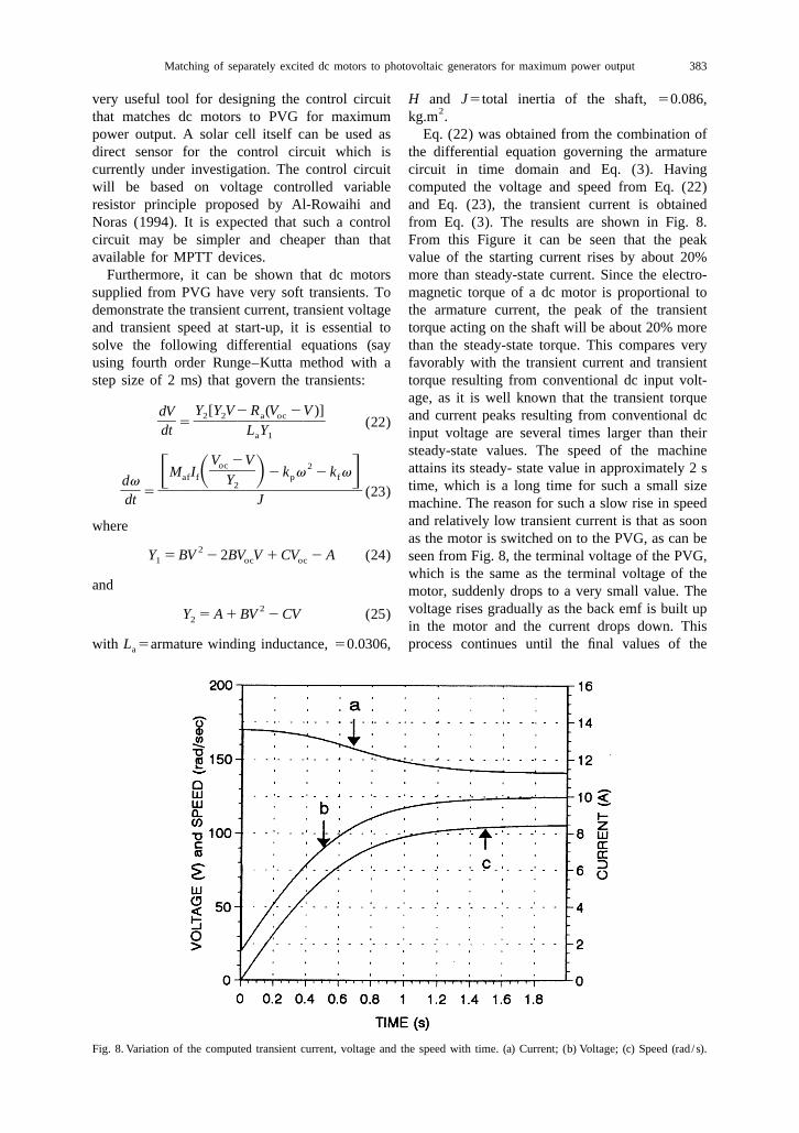
power output. A solar cell itself can be used as Eq. (22) was obtained from the combination ofdirect sensor for the control circuit which is the differential equation governing the armaturecurrently under investigation. The control circuit circuit in time domain and Eq. (3). Havingwill be based on voltage controlled variable computed the voltage and speed from Eq. (22)resistor principle proposed by Al-Rowaihi and and Eq. (23), the transient current is obtainedNoras (1994). It is expected that such a control from Eq. (3). The results are shown in Fig. 8.circuit may be simpler and cheaper than that From this Figure it can be seen that the peakavailable for MPTT devices. value of the starting current rises by about 20%
Furthermore, it can be shown that dc motors more than steady-state current. Since the electro-supplied from PVG have very soft transients. To magnetic torque of a dc motor is proportional todemonstrate the transient current, transient voltage the armature current, the peak of the transientand transient speed at start-up, it is essential to torque acting on the shaft will be about 20% moresolve the following differential equations (say than the steady-state torque. This compares veryusing fourth order Runge–Kutta method with a favorably with the transient current and transientstep size of 2 ms) that govern the transients: torque resulting from conventional dc input volt-
age, as it is well known that the transient torqueY [Y V2 R (V 2V )]dV 2 2 a oc and current peaks resulting from conventional dc] ]]]]]]5 (22)dt L Y input voltage are several times larger than theira 1
steady-state values. The speed of the machineV 2Voc 2 attains its steady- state value in approximately 2 s]]M I 2 k v 2 k vF S D Gaf f p fYdv 2 time, which is a long time for such a small size] ]]]]]]]]]]5 (23)dt J machine. The reason for such a slow rise in speed
and relatively low transient current is that as soonwhereas the motor is switched on to the PVG, as can be
2Y 5 BV 2 2BV V 1 CV 2 A (24) seen from Fig. 8, the terminal voltage of the PVG,1 oc oc
which is the same as the terminal voltage of theand motor, suddenly drops to a very small value. The
2 voltage rises gradually as the back emf is built upY 5 A 1 BV 2 CV (25)2in the motor and the current drops down. Thisprocess continues until the final values of thewith L 5armature winding inductance, 50.0306,a
Fig. 8. Variation of the computed transient current, voltage and the speed with time. (a) Current; (b) Voltage; (c) Speed (rad /s).
384 M. Akbaba et al.
speed and hence the final values of the back emf, Appendixload torque, and terminal voltage is reached.
Parameters A of the Akbaba model (Akbabaand Alattawi, 1995) is
5. CONCLUSIONSA 5V /Ioc sc
Because of the natural mismatch between thewhere V is the open circuit voltage of the PVGocoutput I–V characteristic of a PVG and the inputand I is the short circuit current of the PVGscI–V characteristic of dc motors, the power utiliza-(approximately equal to photo generated current)tion efficiency of PVG powered dc motor drivesand B and C are given byis poor. Therefore an efficient matching technique
is required to increase the energy utilization B 5 (Q 2 Q ) /Q , C 5 (Q V 2 Q V ) /Q3 4 5 3 x 4 y 5efficiency and reduce the capital cost of thesystem. In response to this, a procedure is de- whereveloped to express the optimum field current of
Q 5V I (V 2V 2 AI ),3 x x oc y ythe dc motor in terms of maximum power pointcurrent of PVG and the parameters of the motor-
Q 5V I (V 2V 2 AI ),4 y y oc x xpump set. It has been shown that when the fieldcurrent of the motor is adjusted according to the
Q 5V I V I (V 2V ),5 x x y y y xdeveloped relation, the input I–V characteristic ofthe motor closely follows the maximum power
I 5 0.94I , I 5 0.68Ix sc y sctrajectory of the PVG. By this means, at allinsolation levels, the available peak output power
V 5PVG voltage corresponding to I , and V 5x x yof the PVG is utilized by the motor, and thePVG voltage corresponding to Iypower utilization efficiency is maximized. It was
observed that the deviation of the optimum fieldcurrent from rated field current is not too large. REFERENCESThis will help towards easy implementation of the
Akbaba M. and Alattawi M. A. A. (1995) A new model forproposed technique. I–V characteristic of solar cell generators and its applica-
tions. Solar Energy Mater Solar Cells 37, 123–132.It has been shown that the proposed matchingAkbaba M. (1995) Performance analysis of solar cell arraysprocess results in larger output power gain than
loaded with passive loads. Appl Energy J. 12, 209–218.input power gain, which means improved motor Akbaba M. and Fakhro S. Q. (1992) New model for single-
unit representation of induction motor loads, including skinefficiency.effect, for power system transient stability studies. IEEA general expression has been provided to giveProceedings, Part-B 139, 6, 521–533.
the optimum field current that produces best Alghuwainem S. M. (1991) Application of a DC Chopper toMaximize Utilization of Solar-Cell Generators, IEEE/PESmatch, directly in terms of solar radiation level. It1991 Winter Meeting, Paper 91 WM 145–3 EC, New York.is proposed that this expression may be used as a
Alghuwainem S. M. (1992) Steady-state performance of DCbase for designing the control circuit, which may motors supplied from photovoltaic generators with a step up
converter. IEEE Trans. Energy Conversion EC-7, 267–272.be based on the voltage controlled resistanceAl-Rowaihi K. M. and Noras J. M. (1994) A novel linearprinciple given by Al-Rowaihi and Noras (1994).
resistor utilizing MOS transistors with identical sizes andIn view of the simplicity of this expression, it is one controlling voltage. Int. J. Electronics 76, 6, 1083–
1098.expected that the control circuit will be simplerAppelbaum J. (1986) Starting and steady-state characteristicsand cheaper than that for existing MPPT devices.
of DC motors powered by solar cell generators. IEEE Trans.It was also observed that dc motors supplied Energy Conversion EC-1, 17–25.
from PVG have very soft transients. The peak Appelbaum J. and Sarma M. S. (1989) The operation ofpermanent magnet DC motors powered by a commontransient armature current is about 20% more thansource of solar cells. IEEE Trans. on Energy Conversion
the rated steady-state armature current. Since the EC-4, 635–642.electromagnetic torque of the dc motor is propor- Hanitsch R. and Hauk R. (1985) Microcomputer controlled
DC chopper for optimal operation of a solar generator-tional to the armature current, the peak of themotor system. In Proceedings of Sixth E.C. Photovoltaic
transient torque acting on the shaft will be about Solar Energy Conference, England.20% more than the steady-state torque. This Iyagawa S. and Kawada Y. (Eds) (1968) Encyclopedic Dic-
tionary of Mathematics, the Mathematical society of Japancompares favorably with the transient current and(Translated by Kenneth O. May), MIT Press, Cambridge,
transient torque resulting from a conventional dc Massachusetts and London.input voltage, as it is well known that the transient Kichak R. A. (1979) Standard power regulator for the
multimission modular spacecraft. In Proceedings of the 14thtorque peak and current peak resulting fromInter-society Energy Conversion Engineering Conference,
conventional dc input voltage are several times USA.larger than their steady-state values. Markvart T. (1994) Solar Electricity, John Wiley and Sons.

Matching of separately excited dc motors to photovoltaic generators for maximum power output 385
Pipes L. A. and Harvil L. R. (1971) Applied Mathematics for Saied M. M. and Hanafy A. A. (1991) Optimal designEngineers and Physicists, McGraw-Hill, New York. parameters for a PV array coupled to a DC motor via a
Roger J. A. (1979) Theory of the direct coupling between DC DC-DC transformer. IEEE Trans. Energy Conversion EC-6,motors and photovoltaic solar arrays. Solar Energy 23, 4, 593–598.193–198. Schoeman J. J. and Van Wyk J. D. (1982) A simplified
Saied M. M. (1988) Matching of DC motors to photovoltaic maximum power controller for terrestrial photovoltaic panelgenerators for maximum daily gross mechanical energy. arrays. IEEE Power Electronics Specialist ConferenceIEEE Trans. Energy Conversion EC-3, 465–472. PESC-82, 361–367.
Saied M. M. and Jaboori M. G. (1989) Optimum solar array Zinger Z. and Braunstein A. (1981) Dynamic matching of aconfiguration and DC motor field parameters for maximum solar-electrical (photovoltaic) system an estimation of theannual output mechanical energy. IEEE Trans. Energy minimum requirements on the matching system. IEEEConversion EC-4, 459–465. Trans. Power Apparatus Systems PAS-100, 3, 1189–1192.