
CHAPTER 4: HIGH ENERGY X-RAY GENERATORS
64
CHAPTER 4: HIGH ENERGY X-RAY GENERATORS: LINEAR ACCELERATORS Jason Matney, MS, PhD
-
Upload
khangminh22 -
Category
Documents
-
view
0 -
download
0
Transcript of CHAPTER 4: HIGH ENERGY X-RAY GENERATORS

CHAPTER 4:HIGH ENERGY X-RAY GENERATORS: LINEAR ACCELERATORS
Jason Matney, MS, PhD

Objectives
Medical electron linear accelerators (often shortened to LINAC)• The Basics• Power SupplyMagnetron/Klystron
• Accelerator structure Standing-Wave/Traveling Wave
• X-Ray vs. e- Therapy Modes

Remember Bremsstrahlung Production?
Electrons are released from cathode and travel to the anode, accelerated in route and attain K.E. as they drop through the potential difference.
As the e- passes in the vicinity of positively charged target all or part of the electron’s energy is dissociated from it and propagates in space as EM radiation
X-ray Energy ranges from 0-KvP (max accelerating potential)

Why do we need a LINAC?• Range of X-ray Energy 0-KvP (max accelerating
potential).
If you want higher energy X-rays…You need to hit the target with “faster” electrons This is the purpose of the accelerator
Khan, Figure 3.9

Depth-Dose Relationship for Different Energy Photons
100%max
×
=
DD
d
dDD
GrentzRays
Contact Therapy
Superficial
orthovoltage
60Co (dmax=0.5cm)
• For lower energies PDD is close to 100% at surface
• As increase energy 100% is at deeper depths
Increase Energy, Increase skin sparing
keV -> MeV energy: even more Skin Sparing
<30kV
10-100 kV
100-500 kV
1.17 & 1.33 MeV

Depth-Dose Relationship for Different Energy Photons
100%max
×
=
DD
d
dDDkeV to MEV: Increase Energy, Increase skin sparing, deeper penetration

Cutaway Diagram of Varian Linac
Khan, Figure 4.8C

Microwave Power = Photons!
E=hv h=6.626*10-34 J*s v = frequency (1/s) Microwaves have very High Frequencies
High Energy
JeV 1910*6.1 −= λν=c

Resonance• Resonance causes an object to move back and forth or
up and down. This motion is generally called oscillation.
• When the force application frequency matches the natural frequency of an object it will begin to resonate.
• The forcing function adds energy at just the right moment during the oscillation cycle so that the oscillation is reinforced. This makes the oscillation's amplitude grow larger and larger. It’s like pushing a swing… lots of little pushes at the right time…

Resonance• In Radiation therapy microwave devices make
extensive use of resonant microwave cavities: Magnetrons Klystrons Accelerator Structure
• The resonance Phenomenon occurs at 3000MHz(corresponding to a 10cm wavelength), which is determined by the dimensions of the cavity. Cavities are formed of copper for high electrical and
thermal conductivity.
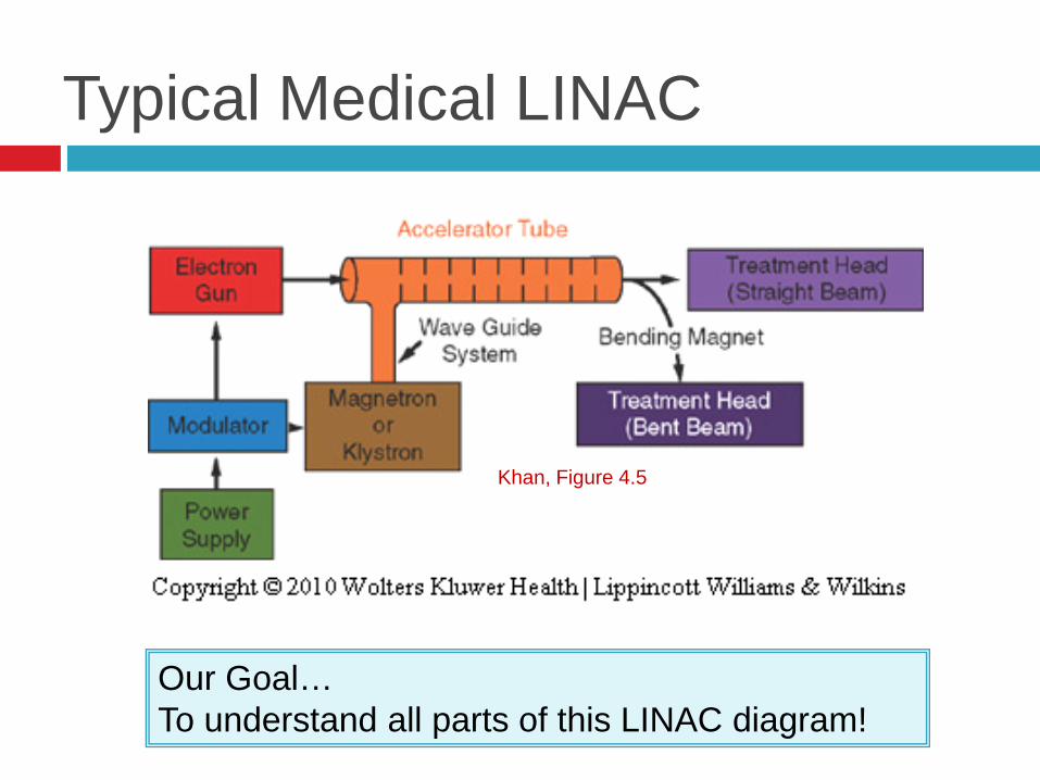
Typical Medical LINAC
Our Goal…To understand all parts of this LINAC diagram!
Khan, Figure 4.5

LINAC Components: Varian “Clinac”
Karzmark and Morton, Figure 15

Basic LINAC Components
1. Modulator – Simultaneously provides high voltage DC pulses to the magnetron or klystron and e- gun.
2. Magnetron/Klystron–provides high frequency microwaves.3. Electron Gun – cathode that provides source of electrons injected
into accelerator structure.4. Wave Guide – Carries microwave power from magnetron or
klystron through the accelerator structure.5. Accelerator Structure – Accelerates e-s from an electron gun
using microwave power from magnetron or klystron.6. Treatment Head– Directs, collimates, shapes, and monitors the
treatment beam

Typical Medical LINAC
Khan, Figure 4.5
• Magnetron/Klystron–provides high frequency microwaves.

The Magnetron
• Device that PRODUCESmicrowaves
• Cylindrical construction w/central cathode and outer anode w/resonant cavities
Khan, Figure 4.6

MagnetronThe Steps to Generate Microwaves
1. Cathode heated by inner filament. e- released by thermionic
emission.
2. Static magnetic field applied perpendicular to the plane of cavities cross-section.
3. Pulsed DC electric field applied between anode and cathode. accelerating power
Khan, Figure 4.6c

Magnetron
The Results The e-s released from cathode are accelerated
toward the anode by the action of pulsed DC electric field. e-s move in complex spirals toward the resonant
cavities (due to influence of magnetic field), radiating energy in the form of microwaves.
Microwaves are lead to accelerator structure via “waveguide”. Resonant Frequency 3000MHz

Klystron• Klystron = Microwave Amplifier driven by low power
microwave oscillator.• Different from magnetron, does NOT generate
microwaves.

KlystronThe steps of Microwave Amplification
1. Cathode heated by hot wire e-s released via thermionic emission.
2. Low level microwaves injected into buncher cavity. Setup alternating electric field across the gap
between left and right cavity walls
3. Velocity Modulation Let’s talk about this step in detail!!

Klystron-The steps of microwave amplification
Step 3. Velocity Modulation More Details
a
b
c
• Fast electrons that arrive in buncher cavity early, between points a and b, encounter a retarding Electric Field Slowed
• Electrons that arrive at time b, when Electric Field=0 velocity unaffected
• Slower e-s that arrive at buncher cavity later, between b and c encounter accelerating Electric Field Accelerated
Net Effecte- stream forms into bunches groups of e-s traveling at same velocity.
- Electric Field Accelerates e-s+ Electric Field Decelerates e-s

KlystronThe Rest of the Steps for Microwave Amplification
4. Drift tube - Distance along which electrons moving at different velocities merge into discrete bunches.
5. Catcher Cavity - As e-s leave drift tube and traverse catcher cavity gap, they generate a retarding electric field (like charges repel) at the ends of the cavity, initiating energy conversion process. the e-s kinetic energy is converted to EM
radiation…microwaves.

KlystronThe Rest of the Steps for Microwave Amplification
6. Microwaves are lead to accelerator structure via wave guide.
7. Collector: Residual beam energy that is not converted to microwave power is dissipated as heat in collector cavity (there are also some x-rays, thus encased in shielding structure).

Klystron• Klystron = Microwave Amplifier driven by low power
microwave oscillator.• Different from magnetron, does NOT generate
microwaves.

Magnetron verses KlystronMagnetron
1. Used in Elekta2. Circular Geometry3. Typical Peak power 2MW
(5MW in newer references)4. Produces high frequency
microwaves5. Sends high frequency
microwaves to accelerator tube via wave guide
Klystron1. Used in Varian and Siemens2. Linear Geometry3. Higher Peak Power 5MW
(7MW in newer references)4. Amplifies Low frequency
microwaves, resulting in high frequency microwaves
5. Sends high frequency microwaves to accelerator tube via wave guide
Same Result High Frequency microwaves to Accelerator Tube

Typical Medical LINAC
Let’s discuss the accelerator tube in more detail.

Accelerator Tube Once we have microwave accelerating power
(from either magnatron or klystron), we need a place to accelerate electrons:
Accelerator Tube (Two Types) Traveling Wave Standing Wave
Don’t lose site of the goal:Accelerator Structure
Accelerates electrons from an electron gun usingmicrowave power from magnetron or klystron

Traveling Wave-The Basics
High frequency microwaves are transmitted down evacuated tube through accelerating cavities (≈ 3000 MHz).
A pre-buncher is used to reduce the velocity of EM wave to correspond to speed of injected e-s. e-s travel at crest of wave and undergo acceleration.
EM waves are absorbed at end of accelerator to prevent backward reflected wave (which would interact with incoming waves).

Traveling WaveSurfer Analogy
Traveling Wave Principlea. A boy surfing on water wave,
accelerates to the right.b. e-s occupying a similar
position on an advancing negative “E” field.
c. Associated charge distribution that pushes (- charge) and pulls (+ charge) the e-bunches along the cylinder4 cavities per l
Karzmark and Morton, Figure 28

Standing Wave-The Basics1. Microwave power is fed into the structure via input wave guide at
proximal end (e- gun end).2. Incident wave reflected backward.3. Now we have 2 waves:
Incident wave Reflected wave
4. The 2 waves are reflected back and forth from one end of the accelerator tube to the other many times.
5. The effective electric field is the sum of the forward and backward waves. Magnitude of E fields is additive when the forward and backward waves
are in same direction. Magnitude of E field cancels out when forward and backward waves are in
opposing directions.

Creating a Standing Wave Standing Wave Produced when 2 traveling waves of equal period
and amplitude travel through waveguide in opposite directions!
In accelerator the forward and backward waves exist simultaneously, shown separately here for clarity.
Karzmark and Morton, Figure 29

Standing Wave
Standing wave “E” field patterns in an accelerator structure for combined forward and backward waves @ three instances in time.
Every other cavity “zero” electric field essential in transporting microwave power, but do not contribute to e-acceleration. Role=transfer and couple
power bet cavities Can be moved off axis to
shorten length of cavity One in 4 cavities “negative”.
Karzmark and Morton, Figure 30

Bimodal (Side-Coupled) Accelerator
Optimize cavities along the beam axis for acceleration
Optimize off-axis cavities for microwave power transport
Every other cavity “zero” electric fieldessential in transporting microwave power, but do not contribute to e- acceleration Role=transfer and couple power
bet cavities
Can be moved off axis to shorten length of cavity
Result shorter Accelerator Structure, less space required in Rx room.

Accelerator Tube Example
Elekta linac accelerator tube

Traveling Wave vs Standing Wave
Standing Wave More stable More expensive Shorter accelerator structure
Due to bimodal configuration Manufacturers
Varian Siemens
Usually used with KlystronNote: Single Energy (6X) standing wave accelerators often use Magnetrons
Traveling Wave Less stable Less expensive Longer accelerator structure Manufacturers
Elekta Usually used with Magnetron

Changing the beam energy will be different for traveling-wave and standing-wave accelerators.
What about LINACs with more than one beam energy?

Dual X-ray Energy ModeA Summary
Standing-wave1. Change ratio of
microwaves fed into first and second portions of cavity
• Energy Switch:• High-power Microwave Circuit
2. Broad band buncher.
Traveling Wave1. Beam Loading
• Increasing injected beam current from gun and keeping magnetron or klystron power constant
Remember: Wave travels only in forward direction• Amplitude of the “E” field in the
second portion of accelerator structure can be changed without significant effect on first portion (capture and buncher)
Karzmark, pg 26-28

Where are we aiming the beam?
One more step…..

First things firstWhere is the beam aimed
Low energy, ≤ 6MV (standing wave) LINACs Relatively short accelerator tube is vertically mounted,
electrons proceed straight from accelerator tube to target.
High energy ≥ 6 MV (standing Wave) LINACs Accelerator tube too long to vertically mount, so
horizontally mount the accelerator tube.
But now we have a problem we have horizontal beam, BUT we want “vertical” beam!!
The solution = Bending Magnets

Bending Magnet – 270 degrees
Deflects beam in 270o loop. Lower energy e-s are deflected
through smaller radius loop. Higher energy e-s are deflected
through larger radius loop.
All components brought back together at same position, angle, and beam cross section as when they left accelerator structure

Bending Magnet – Slalom Style
Figure is from: Tim Waldron “The Theory and Operation of Computer-Controlled Medical linear Accelerators". 2002 AAPM Annual Meeting, Refresher Course. MO-A-517A-01 7/15/02

What are we going to hit with it?
Do we want to treat with photons or electrons?
Now that we have that high energy e- Beam, How do we make it useful for Rx?
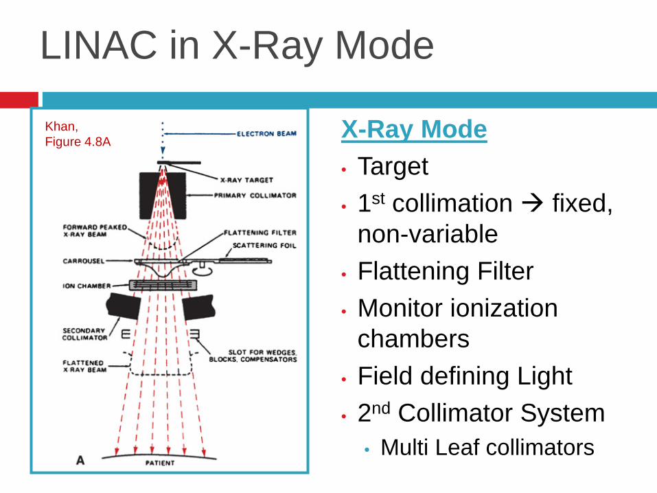
LINAC in X-Ray Mode
X-Ray Mode• Target• 1st collimation fixed,
non-variable• Flattening Filter• Monitor ionization
chambers• Field defining Light• 2nd Collimator System
• Multi Leaf collimators
Khan, Figure 4.8A

LINAC in X-Ray Mode
X-Ray Mode• Target
Khan, Figure 4.8A

e-
Target
Flattening filter
• thick at center
• thin at edges
Attenuates more photons from center less from edges:
Flatter beam, covers more area
Flattened X-Ray Beam
Forward peaked x-ray beam
Flattening Filter
• High energy x-rays are forward peaked, max intensity located centrally with decreased intensity at periphery.

LINAC in X-Ray Mode
X-Ray Mode• Monitor ionization
chambers
Khan, Figure 4.8A

Monitor Ionization Chamber• Dose Rate of accelerator beam may very unpredictable.
• Therefore, cannot to rely on elapsed time to control dose delivered to patient.
• Radiation leaving target or scattering foil passes through monitor ionization chamber. Radiation produces ionization current proportional to beam
Intensity. Current is converted to “monitor units” or MU
Purpose of monitor ionization chamber: Dose to patient controlled by programming accelerator to
deliver prescribed # MU. Monitor field symmetry.

LINAC Light Field
To help see the “projected” field on our patients Mirror slides into place for visual verification,
moves out of beam path when in use

Multileaf collimators
Devices using thick “leaves” of High Z material that help shape the exiting photon field laterally.

Multileaf collimators

LINAC in e- Mode
Electron Mode• Scattering Foil• Monitor ionization chambers• Field defining Light• Collimator System 2nd e- collimation = cone,
downstream of photon collimators placed close to skin to dec. e- scatter in air
3rd e- collimation = cutoutdownstream of cone custom shape field to match Rx site
Note: Beam flatness depends on design of cone or applicator.
e- mode NO TARGET!!
Khan, Figure 4.8B

LINAC: e- Mode Scattering Foils
Electron beam exits as narrow pencil beam with a small diameter. Need to spread it out to be clinically useful.
Effect of a single foil Gaussian distribution Unusable beam Dual Foil System
2 High Z Foils separated by air gap2nd foil thicker at center to even distribution that results
after beam passes through 1st foil
Note: thin foil, causes electrons to scatter i.e. spread out, thicker foils would result Brems. x-rays.

Electron Applicators or “Cones”
Electrons are more likely to scatter in air and require additional, “closer” collimation
Final field shaping of electron field by applicator and special insert Lead insert custom
shaped to specific treatment field size
Cerrobend: 50% Bi, 27% Pb, 13% Sn , 10% Cd

Beam CurrentPhoton verses Electron Mode
Beam current - number of electrons ejected from electron gun.
Beam current is much higher in photon mode. Recall: Bremsstrahlung production is inefficient. Some of the photons are attenuated in flattening
filter.

Cutaway Diagram of Varian Linac
Khan, Figure 4.8C

If that was not too painful…
Practice Questions

Question 1:
The purpose of a scattering foil in the electron mode of LINAC is to : A. Absorb scattered electrons.B. Change x-ray beam into electrons.C. Shield the ion chambers.D. Absorb excess RF energyE. Broaden and flatten the beam.
Correct Answer: E. Changes narrow beam into a broader beam by forcing the electron path to spread due to collisions in the foil!

Question 2
Which of the following does NOT occur when LINAC is changed from x-ray mode to electron mode ? (excluding units with scanned electron beams) .A. The target is removed.B. Scattering foil is placed in the beam.C. The monitor chamber is removed.D. An electron applicator is attached.E. The beam current decreases.
Correct Answer: C. Monitor chamber NOT removed must monitor beam output for all modalities

Question 3 Klystrons and Magnetrons are:
A. Devices used to bend beams of electrons.B. Located in treatment head of the LINAC.C. Beam focusing devices.D. Sources of microwave power.E. Part of the LINAC timer circuit.
Correct Answer: D. Sources of microwave power (Magnetrons generate microwaves, klystrons amplify microwaves)
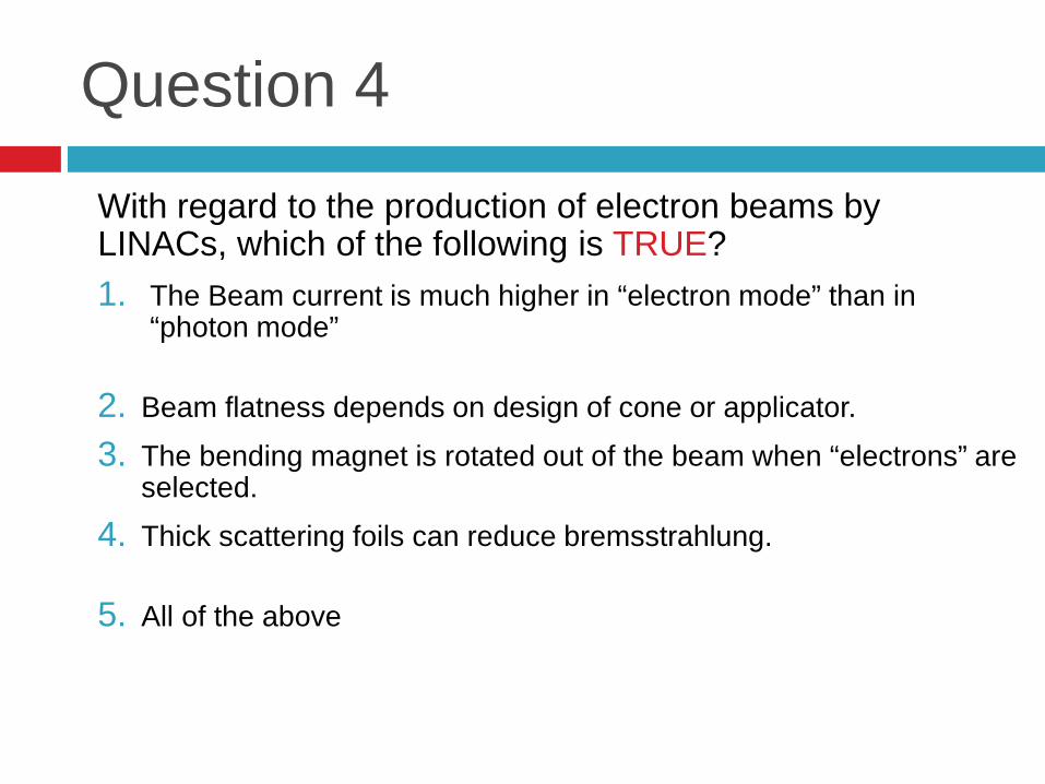
Question 4
With regard to the production of electron beams by LINACs, which of the following is TRUE?1. The Beam current is much higher in “electron mode” than in
“photon mode” No photon production inefficient, need more current
2. Beam flatness depends on design of cone or applicator. TRUE3. The bending magnet is rotated out of the beam when “electrons” are
selected. No required to point electrons down toward isocenter.4. Thick scattering foils can reduce bremsstrahlung. No thicker foils
result in more interactions and produce more x-rays!5. All of the above

References
1. The Physics of Radiation Therapy 4th Ed., Faiz Khan
2. A Primer on Theory and Operation of Linear Accelerators in Radiation Therapy, C.J. Karzmark and Robert Morton
3. Linear Accelerators for Radiation Therapy, 2nd edition, D. Greene and P.C. Williams
4. Radiation Therapy Physics, 2nd edition, William Hende and Geoffrey Ibbott
5. “Theory and Operation of Computer Controlled Medical Linear Accelerators”, Handout form 2002 AAPM Refresher course, Tim Waldron