Power Quality Improvement of Synchronous Generators Using ...
Upload
khangminh22Category
view
1download
0
x
AWG5000 and AWG7000 SeriesArbitrary Waveform GeneratorsZZZ
Quick Start User Manual
*P071248103*
071-2481-03


AWG5000 and AWG7000 SeriesArbitrary Waveform GeneratorsZZZ
Quick Start User Manual
xx
This document supports software version 4.1.
www.tektronix.com071-2481-03

Copyright © Tektronix. All rights reserved. Licensed software products are owned by Tektronix or its subsidiaries or suppliers, and areprotected by national copyright laws and international treaty provisions.
Tektronix products are covered by U.S. and foreign patents, issued and pending. Information in this publication supersedes that in allpreviously published material. Specifications and price change privileges reserved.
TEKTRONIX and TEK are registered trademarks of Tektronix, Inc.
Contacting TektronixTektronix, Inc.14150 SW Karl Braun DriveP.O. Box 500Beaverton, OR 97077USA
For product information, sales, service, and technical support:In North America, call 1-800-833-9200.Worldwide, visit www.tektronix.com to find contacts in your area.

WarrantyTektronix warrants that this product will be free from defects in materials and workmanship for a period of one (1) year from the date ofshipment. If any such product proves defective during this warranty period, Tektronix, at its option, either will repair the defectiveproduct without charge for parts and labor, or will provide a replacement in exchange for the defective product. Parts, modules andreplacement products used by Tektronix for warranty work may be new or reconditioned to like new performance. All replacedparts, modules and products become the property of Tektronix.
In order to obtain service under this warranty, Customer must notify Tektronix of the defect before the expiration of the warranty periodand make suitable arrangements for the performance of service. Customer shall be responsible for packaging and shipping thedefective product to the service center designated by Tektronix, with shipping charges prepaid. Tektronix shall pay for the return of theproduct to Customer if the shipment is to a location within the country in which the Tektronix service center is located. Customer shallbe responsible for paying all shipping charges, duties, taxes, and any other charges for products returned to any other locations.
This warranty shall not apply to any defect, failure or damage caused by improper use or improper or inadequate maintenance andcare. Tektronix shall not be obligated to furnish service under this warranty a) to repair damage resulting from attempts by personnelother than Tektronix representatives to install, repair or service the product; b) to repair damage resulting from improper use orconnection to incompatible equipment; c) to repair any damage or malfunction caused by the use of non-Tektronix supplies; ord) to service a product that has been modified or integrated with other products when the effect of such modification or integrationincreases the time or difficulty of servicing the product.
THIS WARRANTY IS GIVEN BY TEKTRONIX WITH RESPECT TO THE PRODUCT IN LIEU OF ANY OTHER WARRANTIES,EXPRESS OR IMPLIED. TEKTRONIX AND ITS VENDORS DISCLAIM ANY IMPLIED WARRANTIES OF MERCHANTABILITY ORFITNESS FOR A PARTICULAR PURPOSE. TEKTRONIX' RESPONSIBILITY TO REPAIR OR REPLACE DEFECTIVE PRODUCTSIS THE SOLE AND EXCLUSIVE REMEDY PROVIDED TO THE CUSTOMER FOR BREACH OF THIS WARRANTY. TEKTRONIXAND ITS VENDORS WILL NOT BE LIABLE FOR ANY INDIRECT, SPECIAL, INCIDENTAL, OR CONSEQUENTIAL DAMAGESIRRESPECTIVE OF WHETHER TEKTRONIX OR THE VENDOR HAS ADVANCE NOTICE OF THE POSSIBILITY OF SUCHDAMAGES.
[W2 – 15AUG04]


Table of Contents
Table of ContentsGeneral Safety Summary . . . . . . . . . . . . . . . . . . . . . . . . . . . . . . . . . . . . . . . . . . . . . . . . . . . . . . . . . . . . . . . . . . . . . . . . . . . . . . . . . . . . . . . . . . . . . . . . . . . . . . . . . . . . . iiiCompliance Information . . . . . . . . . . . . . . . . . . . . . . . . . . . . . . . . . . . . . . . . . . . . . . . . . . . . . . . . . . . . . . . . . . . . . . . . . . . . . . . . . . . . . . . . . . . . . . . . . . . . . . . . . . . . . . . v
EMC Compliance. . . . . . . . . . . . . . . . . . . . . . . . . . . . . . . . . . . . . . . . . . . . . . . . . . . . . . . . . . . . . . . . . . . . . . . . . . . . . . . . . . . . . . . . . . . . . . . . . . . . . . . . . . . . . . . . . vSafety Compliance . . . . . . . . . . . . . . . . . . . . . . . . . . . . . . . . . . . . . . . . . . . . . . . . . . . . . . . . . . . . . . . . . . . . . . . . . . . . . . . . . . . . . . . . . . . . . . . . . . . . . . . . . . . . . . . viEnvironmental Considerations. . . . . . . . . . . . . . . . . . . . . . . . . . . . . . . . . . . . . . . . . . . . . . . . . . . . . . . . . . . . . . . . . . . . . . . . . . . . . . . . . . . . . . . . . . . . . . . . . . vii
Preface . . . . . . . . . . . . . . . . . . . . . . . . . . . . . . . . . . . . . . . . . . . . . . . . . . . . . . . . . . . . . . . . . . . . . . . . . . . . . . . . . . . . . . . . . . . . . . . . . . . . . . . . . . . . . . . . . . . . . . . . . . . . . . . viiiKey Features . . . . . . . . . . . . . . . . . . . . . . . . . . . . . . . . . . . . . . . . . . . . . . . . . . . . . . . . . . . . . . . . . . . . . . . . . . . . . . . . . . . . . . . . . . . . . . . . . . . . . . . . . . . . . . . . . . . viiiDocumentation . . . . . . . . . . . . . . . . . . . . . . . . . . . . . . . . . . . . . . . . . . . . . . . . . . . . . . . . . . . . . . . . . . . . . . . . . . . . . . . . . . . . . . . . . . . . . . . . . . . . . . . . . . . . . . . . . . . xConventions Used in this Manual . . . . . . . . . . . . . . . . . . . . . . . . . . . . . . . . . . . . . . . . . . . . . . . . . . . . . . . . . . . . . . . . . . . . . . . . . . . . . . . . . . . . . . . . . . . . . . . x
Installing Your Instrument . . . . . . . . . . . . . . . . . . . . . . . . . . . . . . . . . . . . . . . . . . . . . . . . . . . . . . . . . . . . . . . . . . . . . . . . . . . . . . . . . . . . . . . . . . . . . . . . . . . . . . . . . . . . . 1Standard Accessories. . . . . . . . . . . . . . . . . . . . . . . . . . . . . . . . . . . . . . . . . . . . . . . . . . . . . . . . . . . . . . . . . . . . . . . . . . . . . . . . . . . . . . . . . . . . . . . . . . . . . . . . . . . . 1Operating Requirements. . . . . . . . . . . . . . . . . . . . . . . . . . . . . . . . . . . . . . . . . . . . . . . . . . . . . . . . . . . . . . . . . . . . . . . . . . . . . . . . . . . . . . . . . . . . . . . . . . . . . . . . . 2Powering on the Instrument . . . . . . . . . . . . . . . . . . . . . . . . . . . . . . . . . . . . . . . . . . . . . . . . . . . . . . . . . . . . . . . . . . . . . . . . . . . . . . . . . . . . . . . . . . . . . . . . . . . . . 3Powering off the Instrument . . . . . . . . . . . . . . . . . . . . . . . . . . . . . . . . . . . . . . . . . . . . . . . . . . . . . . . . . . . . . . . . . . . . . . . . . . . . . . . . . . . . . . . . . . . . . . . . . . . . . 4Windows Interface Guidelines . . . . . . . . . . . . . . . . . . . . . . . . . . . . . . . . . . . . . . . . . . . . . . . . . . . . . . . . . . . . . . . . . . . . . . . . . . . . . . . . . . . . . . . . . . . . . . . . . . . 4Connecting to a Network. . . . . . . . . . . . . . . . . . . . . . . . . . . . . . . . . . . . . . . . . . . . . . . . . . . . . . . . . . . . . . . . . . . . . . . . . . . . . . . . . . . . . . . . . . . . . . . . . . . . . . . . . 5Setting GPIB/LAN . . . . . . . . . . . . . . . . . . . . . . . . . . . . . . . . . . . . . . . . . . . . . . . . . . . . . . . . . . . . . . . . . . . . . . . . . . . . . . . . . . . . . . . . . . . . . . . . . . . . . . . . . . . . . . . . 5Controlling the Instrument Using a Remote PC. . . . . . . . . . . . . . . . . . . . . . . . . . . . . . . . . . . . . . . . . . . . . . . . . . . . . . . . . . . . . . . . . . . . . . . . . . . . . . . . . 6Offline Mode . . . . . . . . . . . . . . . . . . . . . . . . . . . . . . . . . . . . . . . . . . . . . . . . . . . . . . . . . . . . . . . . . . . . . . . . . . . . . . . . . . . . . . . . . . . . . . . . . . . . . . . . . . . . . . . . . . . . . . 6Inspecting Your Instrument . . . . . . . . . . . . . . . . . . . . . . . . . . . . . . . . . . . . . . . . . . . . . . . . . . . . . . . . . . . . . . . . . . . . . . . . . . . . . . . . . . . . . . . . . . . . . . . . . . . . . . 7Self Calibration . . . . . . . . . . . . . . . . . . . . . . . . . . . . . . . . . . . . . . . . . . . . . . . . . . . . . . . . . . . . . . . . . . . . . . . . . . . . . . . . . . . . . . . . . . . . . . . . . . . . . . . . . . . . . . . . . . . 8Preventing Instrument Damage . . . . . . . . . . . . . . . . . . . . . . . . . . . . . . . . . . . . . . . . . . . . . . . . . . . . . . . . . . . . . . . . . . . . . . . . . . . . . . . . . . . . . . . . . . . . . . . . . 9Option Installation . . . . . . . . . . . . . . . . . . . . . . . . . . . . . . . . . . . . . . . . . . . . . . . . . . . . . . . . . . . . . . . . . . . . . . . . . . . . . . . . . . . . . . . . . . . . . . . . . . . . . . . . . . . . . . . 10
Creating Operating System Restore Discs . . . . . . . . . . . . . . . . . . . . . . . . . . . . . . . . . . . . . . . . . . . . . . . . . . . . . . . . . . . . . . . . . . . . . . . . . . . . . . . . . . . . . . . . . . 11Creating Restore Discs . . . . . . . . . . . . . . . . . . . . . . . . . . . . . . . . . . . . . . . . . . . . . . . . . . . . . . . . . . . . . . . . . . . . . . . . . . . . . . . . . . . . . . . . . . . . . . . . . . . . . . . . . 11Restoring the Instrument Operating System . . . . . . . . . . . . . . . . . . . . . . . . . . . . . . . . . . . . . . . . . . . . . . . . . . . . . . . . . . . . . . . . . . . . . . . . . . . . . . . . . . . 11
Front Panel. . . . . . . . . . . . . . . . . . . . . . . . . . . . . . . . . . . . . . . . . . . . . . . . . . . . . . . . . . . . . . . . . . . . . . . . . . . . . . . . . . . . . . . . . . . . . . . . . . . . . . . . . . . . . . . . . . . . . . . . . . . . 13Rear Panel (AWG7000C Series). . . . . . . . . . . . . . . . . . . . . . . . . . . . . . . . . . . . . . . . . . . . . . . . . . . . . . . . . . . . . . . . . . . . . . . . . . . . . . . . . . . . . . . . . . . . . . . . . . . . . 14
Dynamic Jump In Connector (AWG7000C Series) . . . . . . . . . . . . . . . . . . . . . . . . . . . . . . . . . . . . . . . . . . . . . . . . . . . . . . . . . . . . . . . . . . . . . . . . . . . . 15Rear Panel (AWG5000C Series). . . . . . . . . . . . . . . . . . . . . . . . . . . . . . . . . . . . . . . . . . . . . . . . . . . . . . . . . . . . . . . . . . . . . . . . . . . . . . . . . . . . . . . . . . . . . . . . . . . . . 16Getting Acquainted with Your Instrument . . . . . . . . . . . . . . . . . . . . . . . . . . . . . . . . . . . . . . . . . . . . . . . . . . . . . . . . . . . . . . . . . . . . . . . . . . . . . . . . . . . . . . . . . . . . 18
Control Panel . . . . . . . . . . . . . . . . . . . . . . . . . . . . . . . . . . . . . . . . . . . . . . . . . . . . . . . . . . . . . . . . . . . . . . . . . . . . . . . . . . . . . . . . . . . . . . . . . . . . . . . . . . . . . . . . . . . . 18Locking and Unlocking the Front Panel Controls . . . . . . . . . . . . . . . . . . . . . . . . . . . . . . . . . . . . . . . . . . . . . . . . . . . . . . . . . . . . . . . . . . . . . . . . . . . . . . 19Touch Screen Interface . . . . . . . . . . . . . . . . . . . . . . . . . . . . . . . . . . . . . . . . . . . . . . . . . . . . . . . . . . . . . . . . . . . . . . . . . . . . . . . . . . . . . . . . . . . . . . . . . . . . . . . . . 20Elo Touchscreen Application. . . . . . . . . . . . . . . . . . . . . . . . . . . . . . . . . . . . . . . . . . . . . . . . . . . . . . . . . . . . . . . . . . . . . . . . . . . . . . . . . . . . . . . . . . . . . . . . . . . . 20Screen Interface. . . . . . . . . . . . . . . . . . . . . . . . . . . . . . . . . . . . . . . . . . . . . . . . . . . . . . . . . . . . . . . . . . . . . . . . . . . . . . . . . . . . . . . . . . . . . . . . . . . . . . . . . . . . . . . . . 21Basic Steps for Using the Arbitrary Waveform Generator . . . . . . . . . . . . . . . . . . . . . . . . . . . . . . . . . . . . . . . . . . . . . . . . . . . . . . . . . . . . . . . . . . . . . 22Run Mode . . . . . . . . . . . . . . . . . . . . . . . . . . . . . . . . . . . . . . . . . . . . . . . . . . . . . . . . . . . . . . . . . . . . . . . . . . . . . . . . . . . . . . . . . . . . . . . . . . . . . . . . . . . . . . . . . . . . . . . 23Accessing Menus and Control Windows . . . . . . . . . . . . . . . . . . . . . . . . . . . . . . . . . . . . . . . . . . . . . . . . . . . . . . . . . . . . . . . . . . . . . . . . . . . . . . . . . . . . . . . 24Changing Control Settings . . . . . . . . . . . . . . . . . . . . . . . . . . . . . . . . . . . . . . . . . . . . . . . . . . . . . . . . . . . . . . . . . . . . . . . . . . . . . . . . . . . . . . . . . . . . . . . . . . . . . . 25Display/Hide Control Windows . . . . . . . . . . . . . . . . . . . . . . . . . . . . . . . . . . . . . . . . . . . . . . . . . . . . . . . . . . . . . . . . . . . . . . . . . . . . . . . . . . . . . . . . . . . . . . . . . 26Status Bar . . . . . . . . . . . . . . . . . . . . . . . . . . . . . . . . . . . . . . . . . . . . . . . . . . . . . . . . . . . . . . . . . . . . . . . . . . . . . . . . . . . . . . . . . . . . . . . . . . . . . . . . . . . . . . . . . . . . . . . 27
AWG5000 and AWG7000 Series Quick Start User Manual i

Table of Contents
Setting the User Preferences . . . . . . . . . . . . . . . . . . . . . . . . . . . . . . . . . . . . . . . . . . . . . . . . . . . . . . . . . . . . . . . . . . . . . . . . . . . . . . . . . . . . . . . . . . . . . . . . . . . 28Changing the Windows Display Style . . . . . . . . . . . . . . . . . . . . . . . . . . . . . . . . . . . . . . . . . . . . . . . . . . . . . . . . . . . . . . . . . . . . . . . . . . . . . . . . . . . . . . . . . . 29Run State Control and Output On/Off . . . . . . . . . . . . . . . . . . . . . . . . . . . . . . . . . . . . . . . . . . . . . . . . . . . . . . . . . . . . . . . . . . . . . . . . . . . . . . . . . . . . . . . . . . 30Setting Output Signals . . . . . . . . . . . . . . . . . . . . . . . . . . . . . . . . . . . . . . . . . . . . . . . . . . . . . . . . . . . . . . . . . . . . . . . . . . . . . . . . . . . . . . . . . . . . . . . . . . . . . . . . . . 32Interleave . . . . . . . . . . . . . . . . . . . . . . . . . . . . . . . . . . . . . . . . . . . . . . . . . . . . . . . . . . . . . . . . . . . . . . . . . . . . . . . . . . . . . . . . . . . . . . . . . . . . . . . . . . . . . . . . . . . . . . . . 36Digital Output (Option 03). . . . . . . . . . . . . . . . . . . . . . . . . . . . . . . . . . . . . . . . . . . . . . . . . . . . . . . . . . . . . . . . . . . . . . . . . . . . . . . . . . . . . . . . . . . . . . . . . . . . . . . 39
Saving and Recalling Setups. . . . . . . . . . . . . . . . . . . . . . . . . . . . . . . . . . . . . . . . . . . . . . . . . . . . . . . . . . . . . . . . . . . . . . . . . . . . . . . . . . . . . . . . . . . . . . . . . . . . . . . . . 40File Menu . . . . . . . . . . . . . . . . . . . . . . . . . . . . . . . . . . . . . . . . . . . . . . . . . . . . . . . . . . . . . . . . . . . . . . . . . . . . . . . . . . . . . . . . . . . . . . . . . . . . . . . . . . . . . . . . . . . . . . . . 40Saving an Instrument Setup . . . . . . . . . . . . . . . . . . . . . . . . . . . . . . . . . . . . . . . . . . . . . . . . . . . . . . . . . . . . . . . . . . . . . . . . . . . . . . . . . . . . . . . . . . . . . . . . . . . . 41Recalling an Instrument Setup . . . . . . . . . . . . . . . . . . . . . . . . . . . . . . . . . . . . . . . . . . . . . . . . . . . . . . . . . . . . . . . . . . . . . . . . . . . . . . . . . . . . . . . . . . . . . . . . . 42Default Setup . . . . . . . . . . . . . . . . . . . . . . . . . . . . . . . . . . . . . . . . . . . . . . . . . . . . . . . . . . . . . . . . . . . . . . . . . . . . . . . . . . . . . . . . . . . . . . . . . . . . . . . . . . . . . . . . . . . . 43Changing Settings at Power-On . . . . . . . . . . . . . . . . . . . . . . . . . . . . . . . . . . . . . . . . . . . . . . . . . . . . . . . . . . . . . . . . . . . . . . . . . . . . . . . . . . . . . . . . . . . . . . . . 43Importing Waveform Data. . . . . . . . . . . . . . . . . . . . . . . . . . . . . . . . . . . . . . . . . . . . . . . . . . . . . . . . . . . . . . . . . . . . . . . . . . . . . . . . . . . . . . . . . . . . . . . . . . . . . . . 44Exporting Waveform Data . . . . . . . . . . . . . . . . . . . . . . . . . . . . . . . . . . . . . . . . . . . . . . . . . . . . . . . . . . . . . . . . . . . . . . . . . . . . . . . . . . . . . . . . . . . . . . . . . . . . . . 48
Waveform Display and Edit . . . . . . . . . . . . . . . . . . . . . . . . . . . . . . . . . . . . . . . . . . . . . . . . . . . . . . . . . . . . . . . . . . . . . . . . . . . . . . . . . . . . . . . . . . . . . . . . . . . . . . . . . . 50Waveform Window . . . . . . . . . . . . . . . . . . . . . . . . . . . . . . . . . . . . . . . . . . . . . . . . . . . . . . . . . . . . . . . . . . . . . . . . . . . . . . . . . . . . . . . . . . . . . . . . . . . . . . . . . . . . . . 50Using Zoom . . . . . . . . . . . . . . . . . . . . . . . . . . . . . . . . . . . . . . . . . . . . . . . . . . . . . . . . . . . . . . . . . . . . . . . . . . . . . . . . . . . . . . . . . . . . . . . . . . . . . . . . . . . . . . . . . . . . . 51Creating or Modifying a Waveform . . . . . . . . . . . . . . . . . . . . . . . . . . . . . . . . . . . . . . . . . . . . . . . . . . . . . . . . . . . . . . . . . . . . . . . . . . . . . . . . . . . . . . . . . . . . . 52Creating a Standard Waveform. . . . . . . . . . . . . . . . . . . . . . . . . . . . . . . . . . . . . . . . . . . . . . . . . . . . . . . . . . . . . . . . . . . . . . . . . . . . . . . . . . . . . . . . . . . . . . . . . 53Equation Editor . . . . . . . . . . . . . . . . . . . . . . . . . . . . . . . . . . . . . . . . . . . . . . . . . . . . . . . . . . . . . . . . . . . . . . . . . . . . . . . . . . . . . . . . . . . . . . . . . . . . . . . . . . . . . . . . . . 55Accessing Waveform in a Setup File . . . . . . . . . . . . . . . . . . . . . . . . . . . . . . . . . . . . . . . . . . . . . . . . . . . . . . . . . . . . . . . . . . . . . . . . . . . . . . . . . . . . . . . . . . . 56Changing a User-Defined Waveform Name . . . . . . . . . . . . . . . . . . . . . . . . . . . . . . . . . . . . . . . . . . . . . . . . . . . . . . . . . . . . . . . . . . . . . . . . . . . . . . . . . . . 57Confirming Waveform Properties . . . . . . . . . . . . . . . . . . . . . . . . . . . . . . . . . . . . . . . . . . . . . . . . . . . . . . . . . . . . . . . . . . . . . . . . . . . . . . . . . . . . . . . . . . . . . . . 57Editing a Waveform . . . . . . . . . . . . . . . . . . . . . . . . . . . . . . . . . . . . . . . . . . . . . . . . . . . . . . . . . . . . . . . . . . . . . . . . . . . . . . . . . . . . . . . . . . . . . . . . . . . . . . . . . . . . . 58Math Waveforms . . . . . . . . . . . . . . . . . . . . . . . . . . . . . . . . . . . . . . . . . . . . . . . . . . . . . . . . . . . . . . . . . . . . . . . . . . . . . . . . . . . . . . . . . . . . . . . . . . . . . . . . . . . . . . . . 61Normalize Option. . . . . . . . . . . . . . . . . . . . . . . . . . . . . . . . . . . . . . . . . . . . . . . . . . . . . . . . . . . . . . . . . . . . . . . . . . . . . . . . . . . . . . . . . . . . . . . . . . . . . . . . . . . . . . . . 62Using Other Edit Menu Commands . . . . . . . . . . . . . . . . . . . . . . . . . . . . . . . . . . . . . . . . . . . . . . . . . . . . . . . . . . . . . . . . . . . . . . . . . . . . . . . . . . . . . . . . . . . . 62
Sequence . . . . . . . . . . . . . . . . . . . . . . . . . . . . . . . . . . . . . . . . . . . . . . . . . . . . . . . . . . . . . . . . . . . . . . . . . . . . . . . . . . . . . . . . . . . . . . . . . . . . . . . . . . . . . . . . . . . . . . . . . . . . . 68Sequence Window . . . . . . . . . . . . . . . . . . . . . . . . . . . . . . . . . . . . . . . . . . . . . . . . . . . . . . . . . . . . . . . . . . . . . . . . . . . . . . . . . . . . . . . . . . . . . . . . . . . . . . . . . . . . . . 68Creating a Sequence . . . . . . . . . . . . . . . . . . . . . . . . . . . . . . . . . . . . . . . . . . . . . . . . . . . . . . . . . . . . . . . . . . . . . . . . . . . . . . . . . . . . . . . . . . . . . . . . . . . . . . . . . . . 70Creating a Subsequence . . . . . . . . . . . . . . . . . . . . . . . . . . . . . . . . . . . . . . . . . . . . . . . . . . . . . . . . . . . . . . . . . . . . . . . . . . . . . . . . . . . . . . . . . . . . . . . . . . . . . . . 72Editing a Sequence . . . . . . . . . . . . . . . . . . . . . . . . . . . . . . . . . . . . . . . . . . . . . . . . . . . . . . . . . . . . . . . . . . . . . . . . . . . . . . . . . . . . . . . . . . . . . . . . . . . . . . . . . . . . . 74Event Jump. . . . . . . . . . . . . . . . . . . . . . . . . . . . . . . . . . . . . . . . . . . . . . . . . . . . . . . . . . . . . . . . . . . . . . . . . . . . . . . . . . . . . . . . . . . . . . . . . . . . . . . . . . . . . . . . . . . . . . 76Force Jump To . . . . . . . . . . . . . . . . . . . . . . . . . . . . . . . . . . . . . . . . . . . . . . . . . . . . . . . . . . . . . . . . . . . . . . . . . . . . . . . . . . . . . . . . . . . . . . . . . . . . . . . . . . . . . . . . . . 77Accessing Sequence Elements Outside the Display Area . . . . . . . . . . . . . . . . . . . . . . . . . . . . . . . . . . . . . . . . . . . . . . . . . . . . . . . . . . . . . . . . . . . . 78
Tutorials . . . . . . . . . . . . . . . . . . . . . . . . . . . . . . . . . . . . . . . . . . . . . . . . . . . . . . . . . . . . . . . . . . . . . . . . . . . . . . . . . . . . . . . . . . . . . . . . . . . . . . . . . . . . . . . . . . . . . . . . . . . . . . . 79Creating and Editing a Waveform . . . . . . . . . . . . . . . . . . . . . . . . . . . . . . . . . . . . . . . . . . . . . . . . . . . . . . . . . . . . . . . . . . . . . . . . . . . . . . . . . . . . . . . . . . . . . . 79Creating and Editing a Sequence . . . . . . . . . . . . . . . . . . . . . . . . . . . . . . . . . . . . . . . . . . . . . . . . . . . . . . . . . . . . . . . . . . . . . . . . . . . . . . . . . . . . . . . . . . . . . . 81
Index
ii AWG5000 and AWG7000 Series Quick Start User Manual

General Safety Summary
General Safety SummaryReview the following safety precautions to avoid injury and prevent damage to this product or any products connected to it.
To avoid potential hazards, use this product only as specified.
Only qualified personnel should perform service procedures.
To Avoid Fire or Personal InjuryUse proper power cord. Use only the power cord specified for this product and certified for the country of use.
Ground the product. This product is grounded through the grounding conductor of the power cord. To avoid electricshock, the grounding conductor must be connected to earth ground. Before making connections to the input or outputterminals of the product, ensure that the product is properly grounded.
Observe all terminal ratings. To avoid fire or shock hazard, observe all ratings and markings on the product. Consult theproduct manual for further ratings information before making connections to the product.
Do not apply a potential to any terminal, including the common terminal, that exceeds the maximum rating of that terminal.
Power disconnect. The power cord disconnects the product from the power source. Do not block the power cord; itmust remain accessible to the user at all times.
Do not operate without covers. Do not operate this product with covers or panels removed.
Do not operate with suspected failures. If you suspect that there is damage to this product, have it inspected byqualified service personnel.
Avoid exposed circuitry. Do not touch exposed connections and components when power is present.
Do not operate in wet/damp conditions.
Do not operate in an explosive atmosphere.
Keep product surfaces clean and dry.Provide proper ventilation. Refer to the manual's installation instructions for details on installing the product so it hasproper ventilation.
AWG5000 and AWG7000 Series Quick Start User Manual iii

General Safety Summary
Terms in This ManualThese terms may appear in this manual:
WARNING. Warning statements identify conditions or practices that could result in injury or loss of life.
CAUTION. Caution statements identify conditions or practices that could result in damage to this product or other property.
Symbols and Terms on the ProductThese terms may appear on the product:
DANGER indicates an injury hazard immediately accessible as you read the marking.
WARNING indicates an injury hazard not immediately accessible as you read the marking.
CAUTION indicates a hazard to property including the product.
The following symbol(s) may appear on the product:
iv AWG5000 and AWG7000 Series Quick Start User Manual

Compliance Information
Compliance InformationThis section lists the EMC (electromagnetic compliance), safety, and environmental standards with which the instrumentcomplies.
EMC ComplianceEC Declaration of Conformity – EMCMeets intent of Directive 2004/108/EC for Electromagnetic Compatibility. Compliance was demonstrated to the followingspecifications as listed in the Official Journal of the European Communities:
EN 61326-1 2006. EMC requirements for electrical equipment for measurement, control, and laboratory use. 1 2 3
CISPR 11:2003. Radiated and conducted emissions, Group 1, Class A
IEC 61000-4-2:2001. Electrostatic discharge immunity
IEC 61000-4-3:2002. RF electromagnetic field immunity
IEC 61000-4-4:2004. Electrical fast transient / burst immunity
IEC 61000-4-5:2001. Power line surge immunity
IEC 61000-4-6:2003. Conducted RF immunity
IEC 61000-4-11:2004. Voltage dips and interruptions immunity
EN 61000-3-2:2006. AC power line harmonic emissions
EN 61000-3-3:1995. Voltage changes, fluctuations, and flicker
European contact.Tektronix UK, Ltd.Western PeninsulaWestern RoadBracknell, RG12 1RFUnited Kingdom
1 This product is intended for use in nonresidential areas only. Use in residential areas may cause electromagnetic interference.
2 Emissions which exceed the levels required by this standard may occur when this equipment is connected to a test object.
3 To ensure compliance with the EMC standards listed here, high-quality shielded interface cables should be used.
AWG5000 and AWG7000 Series Quick Start User Manual v

Compliance Information
Australia / New Zealand Declaration of Conformity – EMCComplies with the EMC provision of the Radio communications Act per the following standard, in accordance with ACMA:
CISPR 11:2003. Radiated and Conducted Emissions, Group 1, Class A, in accordance with EN 61326-1:2006.
Safety ComplianceEC Declaration of Conformity – Low VoltageCompliance was demonstrated to the following specification as listed in the Official Journal of the European Communities:
Low Voltage Directive 2006/95/EC.
EN 61010-1: 2001. Safety requirements for electrical equipment for measurement control and laboratory use.
U.S. Nationally Recognized Testing Laboratory ListingUL 61010-1:2004, 2nd Edition. Standard for electrical measuring and test equipment.
Canadian CertificationCAN/CSA-C22.2 No. 61010-1:2004. Safety requirements for electrical equipment for measurement, control, andlaboratory use. Part 1.
Additional CompliancesIEC 61010-1: 2001. Safety requirements for electrical equipment for measurement, control, and laboratory use.
Equipment TypeTest and measuring equipment.
Safety ClassClass 1 – grounded product.
Pollution Degree DescriptionA measure of the contaminants that could occur in the environment around and within a product. Typically the internalenvironment inside a product is considered to be the same as the external. Products should be used only in the environmentfor which they are rated.
Pollution Degree 1. No pollution or only dry, nonconductive pollution occurs. Products in this category are generallyencapsulated, hermetically sealed, or located in clean rooms.
Pollution Degree 2. Normally only dry, nonconductive pollution occurs. Occasionally a temporary conductivity that iscaused by condensation must be expected. This location is a typical office/home environment. Temporary condensationoccurs only when the product is out of service.
vi AWG5000 and AWG7000 Series Quick Start User Manual
Compliance Information
Pollution Degree 3. Conductive pollution, or dry, nonconductive pollution that becomes conductive due to condensation.These are sheltered locations where neither temperature nor humidity is controlled. The area is protected from directsunshine, rain, or direct wind.
Pollution Degree 4. Pollution that generates persistent conductivity through conductive dust, rain, or snow. Typicaloutdoor locations.
Pollution DegreePollution Degree 2 (as defined in IEC 61010-1). Note: Rated for indoor use only.
Environmental ConsiderationsThis section provides information about the environmental impact of the product.
Product End-of-Life HandlingObserve the following guidelines when recycling an instrument or component:
Equipment recycling. Production of this equipment required the extraction and use of natural resources. The equipment maycontain substances that could be harmful to the environment or human health if improperly handled at the product’s end of life. Inorder to avoid release of such substances into the environment and to reduce the use of natural resources, we encourage you torecycle this product in an appropriate system that will ensure that most of the materials are reused or recycled appropriately.
This symbol indicates that this product complies with the applicable European Union requirements accordingto Directives 2002/96/EC and 2006/66/EC on waste electrical and electronic equipment (WEEE) andbatteries. For information about recycling options, check the Support/Service section of the Tektronix Website (www.tektronix.com).
Mercury notification. This product uses an LCD backlight lamp that contains mercury. Disposal may be regulated due toenvironmental considerations. Please contact your local authorities or, within the United States, refer to the E-cycling CentralWeb page (www.eiae.org) for disposal or recycling information. 1
1 Mercury notification does not apply to AWG5000C or AWG7000C series instruments.
Perchlorate materials. This product contains one or more type CR lithium batteries. According to the stateof California, CR lithium batteries are classified as perchlorate materials and require special handling. Seewww.dtsc.ca.gov/hazardouswaste/perchlorate for additional information.
Restriction of Hazardous SubstancesThis product has been classified as Monitoring and Control equipment, and is outside the scope of the 2002/95/EC RoHSDirective.
AWG5000 and AWG7000 Series Quick Start User Manual vii

Preface
PrefaceThis manual describes the installation and operation of AWG5000 and AWG7000 series instruments. Basic operations andconcepts are presented in this manual. For more detailed information, see the online help on your instrument. The followinginstruments are supported by this manual:
AWG7000C Series: AWG7122C AWG7082C
AWG5000C Series: AWG5002C, AWG5012C, AWG5014C
AWG7000B Series: AWG7121B, AWG7122B, AWG7061B, AWG7062B
AWG5000B Series: AWG5012B, AWG5014B, AWG5002B, AWG5004B
Key FeaturesThe following list describes some of the key features of the AWG5000 and AWG7000 series instruments:
Microsoft Windows 7 Professional operating system, AWG5000C and AWG7000C series
Microsoft Windows XP Professional operating system, AWG5000B and AWG7000B series
Extended analog output bandwidth (Option 02 and Option 06)
28-bit digital data output (Option 03), AWG5002B, AWG5012B, AWG5002C, and AWG5012C only
Interleave and extended analog output bandwidth (Option 06), AWG7122B, AWG7122C, and AWG7082C only
Fast sequence switching (Option 08), AWG5000B series, AWG7000B series, and AWG7000C series only
A large 10.4 inch (264.2 mm) high resolution XGA color display
An intuitive, graphical user interface, with built-in online help
Removable hard disk drive
Supports USB 2.0 interface
LAN (1000/100/10 Base-T)
Touch screen user interface
viii AWG5000 and AWG7000 Series Quick Start User Manual

Preface
Table i: AWG5000C and AWG7000C featuresModel AWG7122C AWG7082C AWG5014C AWG5012C AWG5002CMaximumsampling rate
12 GS/s(24 GS/s byinterleave)
8 GS/s (16 GS/sby interleave)
1.2 GS/s 1.2 GS/s 600 MS/s
D/A resolution 8 bits or 10 bits (selectable) 14 bitsWaveformlength
32 M or 64 M (Option 01) 16 M or 32 M (Option 01)
Analog output 2 2 4 2 2Marker output 4 4 8 4 4Maximumanalogamplitude
2 Vpp (standard model)1 Vpp (Option 06)
4.5 Vpp
Maximumamplitudeand analogbandwidth
2 Vp-p, 750 MHz (Normal mode)1 Vp-p, 3.5 GHz (Direct D/A mode)
1 Vp-p, 7.5 GHz (Option 02or Option 06)
2 Vp-p, 250 MHz (Normal mode)0.6 Vp-p, 370 MHz (Direct D/A mode)
Digital dataoutput
N/A N/A N/A 28 bits(Option 03)
28 bits(Option 03)
Table ii: AWG5000B and AWG7000B features
ModelAWG7121B/AWG7122B
AWG7061B/AWG7062B
AWG5012B/AWG5014B
AWG5002B/AWG5004B
Maximum samplingrate
12 GS/s (24 GS/s byinterleave)
6 GS/s 1.2 GS/s 600 MS/s
D/A resolution 8 bits or 10 bits (selectable) 14 bitsWaveform length 32 M or 64 M (Option 01) 16 M or 32 M (Option 01)Analog output 1 or 2 2 or 4Maximum analogamplitude
2 Vpp (standard model)1 Vpp (Option 06)
4.5 Vpp
Maximum amplitudeand analogbandwidth
2 Vp-p, 750 MHz (Normal mode)1 Vp-p, 3.5 GHz (Direct D/A mode)
1 Vp-p, 7.5 GHz (Option 02 or Option 06)
2 Vp-p, 250 MHz (Normal mode)0.6 Vp-p, 370 MHz (Direct D/A mode)
Marker output 1 2 or 4 4 or 8Digital data output N/A 28 bits (Option 03)1 When 10 bits DAC resolution is selected in the AWG7000 series, Marker Output is disabled.
AWG5000 and AWG7000 Series Quick Start User Manual ix

Preface
DocumentationReview the following table to locate more information about this product.
To read about Use these documentsInstallation and operation (overviews) Read the Quick Start User Manual for general information about how to
use your instrument.In-depth operation and user interface help Access the user online help from the Help menu for information on
virtually all controls and elements on screen. Online help includes detailedinstructions for using instrument functions.
Programmer commands Access the programmer online guide from the Help menu. Theprogrammer guide includes the syntax of remote commands.
Specifications and performance verificationprocedures
Read the technical reference documents for specifications and theperformance verification procedures. These documents are available onthe documentation CD.
Service procedures Read the service manuals to service instruments to the modulelevel. The service manuals are available on the Tektronix Web site(www.tektronix.com/manuals).
Conventions Used in this ManualThe following icons are used throughout this manual.
SequenceStep
Front panelpower
Connectpower
Network PS2 SVGA USB
x AWG5000 and AWG7000 Series Quick Start User Manual
Installing Your Instrument
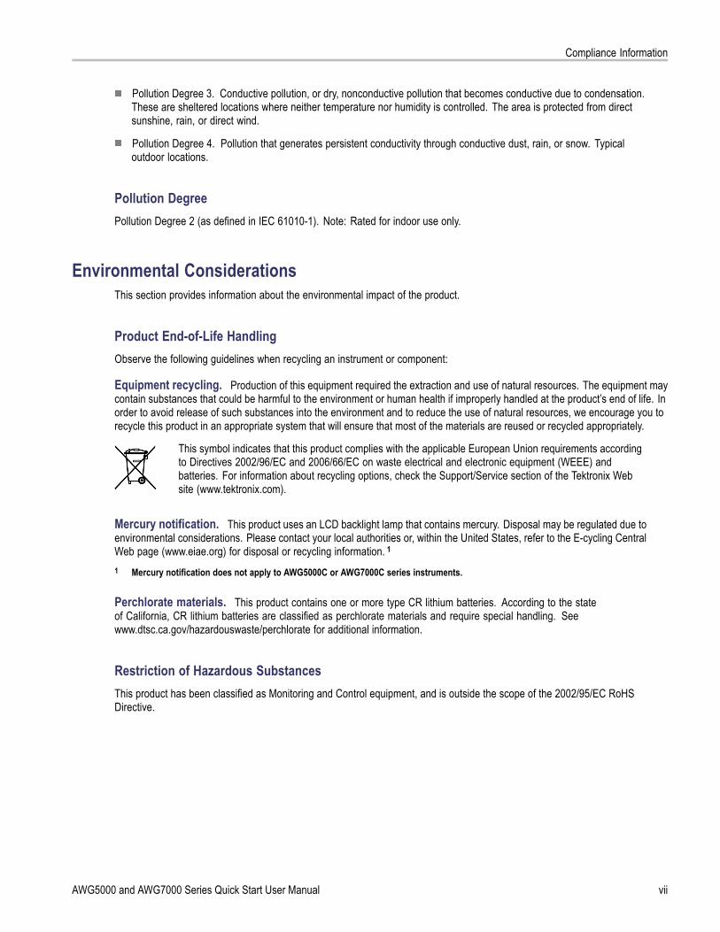
Installing Your InstrumentUnpack the instrument and check that you received all items listed as Standard Accessories. Check the Tektronix Website (www.tektronix.com) for the most current information.
NOTE. The instrument does not ship with a product software CD. To reinstall the product software, go to the Tektronix Website and download the latest product software for your instrument.
Standard AccessoriesAccessory Tektronix part numberAWG5000B and AWG7000B Series Quick Start User Manual
English (Option L0) 071-2481-xxJapanese (Option L5) 071-2482-xxSimplified Chinese (Option L7) 071-2483-xxTraditional Chinese (Option L8) 071-2484-xxRussian (Option L10) 020-2971-xx
Documentation CD 063-4134-xxUser Online Help (part of the product software) ---Programmer Online Help (part of the product software) ---Windows compatible keyboard 119-7083-00Windows compatible mouse 119-7054-00Lead Set for DC Output 012-1697-00Front Protect Cover 200-4963-00Accessory Pouch 016-1441-0150 Ω SMA Termination, Male, DC to 18 GHz (3 each)(AWG7000 series only)
015-1022-01
Power cord – one of the following:North America (Option A0) 161-0104-00Universal Euro (Option A1) 161-0104-06United Kingdom (Option A2) 161-0104-07Australia (Option A3) 161-0104-14Switzerland (Option A5) 161-0167-00Japan (Option A6) 161-A005-00China (Option A10) 161-0306-00India (Option A11) 161-0324-00No power cord or AC adapter(Option A99)
---
AWG5000 and AWG7000 Series Quick Start User Manual 1

Installing Your Instrument
Operating Requirements
CAUTION. To ensure proper cooling, keep sides of the instrument clear of obstructions.
Place the instrument on a cart or bench, observing clearance requirements:
Top: 20 mm (0.8 in)
Left and right side: 150 mm (5.9 in)
Bottom: 20 mm (0.8 in)
Rear: 75 mm (3 in)
Environmental Requirements
Before operating the instrument, ensure that the instrument has warmed up for 20 minutes and meets the environmentalrequirements listed in the following table.
Requirement DescriptionTemperature (operating) 10 °C to 40 °C (+50 °F to +104 °F)Relative humidity (operating) 5% to 95% relative humidity at up to 30 °C (86 °F)
5% to 45% relative humidity above 30 °C (86 °F) up to+40 °C (104 °F) noncondensing, and as limited by amaximum wet-bulb temperature of 29 °C (84.2 °F)
Altitude (operating) Up to 3,000 m (approximately 10,000 feet)
Power Supply Requirements
WARNING. To reduce the risk of fire and shock, ensure that the mains supply voltage fluctuations do not exceed 10% of theoperating voltage range.
Source Voltage and Frequency Power Consumption100 VAC to 240 VAC, 47 Hz to 63 Hz Less than 450 W (AWG7000 series)
Less than 560 W (AWG5000 series)
2 AWG5000 and AWG7000 Series Quick Start User Manual

Installing Your Instrument
Cleaning
WARNING. To avoid personal injury, power off the instrument and disconnect it from line voltage before performing any ofthe following procedures.
Inspect the arbitrary waveform generator as often as operating conditions require. To clean the exterior surface, performthe following steps:
1. Remove loose dust on the outside the instrument with a lint-free cloth. Use care to avoid scratching the front panel display.
2. Use a soft cloth dampened with water to clean the instrument. Use a 75% isopropyl alcohol solution as a cleaner.
CAUTION. To avoid damage to the surface of the arbitrary waveform generator, do not use any abrasive or chemicalcleaning agents.
Powering on the Instrument1. Connect the AC power cord to the rear of
the instrument.
2. Use the front-panel power button toswitch the instrument on.
NOTE. Before using the instrument, create a set of operating system restore discs, to provide a back-up of the system.The instrument does not ship with operating restore media. Refer to the instructions to create the operating restore discs.(See page 11, Creating Operating System Restore Discs.)
AWG5000 and AWG7000 Series Quick Start User Manual 3

Installing Your Instrument
Powering off the Instrument1. Use the front-panel power button to start
the shutdown process.Wait approximately 30 seconds for theinstrument to power off.
2. To completely remove power to theinstrument, perform the shutdown justdescribed, and then remove the powercord from the instrument.
Windows Interface GuidelinesBecause the instrument uses the Microsoft Windows interface, you have open access to the Windows operating system. Youcan access the Windows desktop to load and run other Windows-based applications such as Microsoft Excel, WordPad, andPaint.
Follow these guidelines to avoid making operating system changes that might cause problems or annoyances while trying touse the instrument:
Be careful when making changes in the Control Panel. Avoid making changes to any controls with which you areunfamiliar.
Do not delete or change any system fonts; this can affect the quality of the display.
Do not change the system Display Properties, such as the Background, Appearance, Effects, or Settings. Making suchchanges can affect the usability of the instrument and the touch screen.
Do not change the contents of the Windows folder or the Program Files\Tektronix\AWG\ System folder.
Do not change the BIOS settings; this can affect the overall operation of the instrument.
If you think that your Windows interface might cause problems with the instrument, contact your local Tektronix supportcenter for assistance.
4 AWG5000 and AWG7000 Series Quick Start User Manual

Installing Your Instrument
Connecting to a NetworkYou can connect your instrument to a network for printing, file sharing, Internet access, and other functions. Consult withyour network administrator and use the standard Windows utilities to configure the instrument for your network. For settingGPIB or LAN configuration, use the GPIB/LAN Configuration dialog box from System menu.
Setting GPIB/LAN
Select System > GPIB/LAN Configurationto open the GPIB/LAN Configuration dialogbox.
1. Set the instrument GPIB buscommunication:
Talk/Listen – Select this mode toremotely control the instrument froman external host computer.
Off Bus – Select this mode todisconnect the instrument from theGPIB bus.
2. The instrument supports the VXI-11Server (LAN). Use VXI-11 Server Controlin the Task Tray to Start/Stop VXI-11Server.
3. TCP/IP protocol is also supported. Onand Off of socket communication arecontrolled here. The port number is fixedto 4000.
Quick TipTo start the VXI-11 Server automatically at power-on, check the "Start server automatically at system power on " checkbox in the VXI-11 Server Control.
The following operations cannot be performed through a GPIB or LAN connection:
Editing a waveform
Changing size or name of waveform
Converting the waveform format
Importing waveform data from the AWG5000 series and AWG7000 series setup (*.AWG) file
Importing a Tektronix DTG5000 series file (*.DTG)
Importing a Tektronix AWG400/500/600/700 series SEQ file
Exporting waveform data
AWG5000 and AWG7000 Series Quick Start User Manual 5

Installing Your Instrument
Controlling the Instrument Using a Remote PCYou can use your PC to control the arbitrary waveform generator through a LAN using the Windows Remote Desktopfunction. If your PC has a larger screen, you can edit waveforms easily using your keyboard and mouse. You can also use athird party software installed on your PC to create a waveform and import it through a network.
Offline ModeThe Offline Mode is a function that you can use to run the instrument application on your PC. Install the application on yourPC; the instrument hardware is not required. You can create and edit the instrument setups. The setup files that you createcan be used later with your arbitrary waveform generator.
1. Go to the Tektronix Web site(www.tektronix.com/software) anddownload the latest version of the AWGProduct Software. Follow the instructionsto install the AWG application on yourPC.
2. Before using the offline mode, you mustset up the instrument configuration.From the Windows Start menu, select AllPrograms > Tektronix > AWG > ConfigUtility. The Configuration Utility dialogbox appears.
3. Select your instrument type.
4. Select your instrument optionconfiguration.
5. Click OK.Run the instrument application from theStart menu. The setup configuration youhave made using the Configuration Utilitywill be reflected in the application.
6 AWG5000 and AWG7000 Series Quick Start User Manual

Installing Your Instrument
Inspecting Your InstrumentTwo types of diagnostics are provided to verify the functionality of your instrument:
Power-on self test – Every time you power on the instrument, the instrument automatically performs the internaldiagnostics.
Diagnostics from the System menu – You can also run the internal diagnostics using the System menu. Use thefollowing procedures:
1. Select System > Diagnostics from themenu bar.The Diagnostics dialog box appears.
2. Confirm that the Loop box is notchecked.If Loop is checked, the diagnostics runsuntil it is manually stopped.
3. If you click Select All, all diagnosticitems are checked.You can execute all items together or youcan execute only the selected item(s).
4. Click Execute to start the diagnostics.Verify that the instrument passes alltests. If diagnostic failures occur, contactyour local Tektronix service personnel.
AWG5000 and AWG7000 Series Quick Start User Manual 7

Installing Your Instrument
Self CalibrationThe self calibration uses internal calibration routines that check electrical characteristics such as analog level and markerlevel, and then adjust the internal calibration constants as necessary. Marker level is checked only in the AWG7000 seriesinstruments.
NOTE. Power on the instrument and allow a 20 minute warm-up period before performing this procedure.
1. Confirm that there is no output signal byverifying that the front-panel Run buttonindicator is off.
2. To perform the calibration suite, selectSystem > Calibration from the menubar.The Calibration dialog box appears.
3. Select Execute.
4. A pop-up message asks you to removeall the cables from output connectors.
5. Remove the cables and then select OK.Wait until the calibration completes.For all calibration items, the Statuscontrol should indicate Pass. If it doesnot, contact your local Tektronix servicepersonnel.
NOTE. Self calibration is not valid until the instrument reaches a valid temperature. (See page 2, Operating Requirements.)
NOTE. If your instrument is an AWG7000 series, perform self calibration once a month to maintain the analog and markeroutput level accuracy. Failure to do so can prevent the instrument from meeting warranted performance levels for analogand marker output.
If your instrument is an AWG5000 series, perform self calibration once a year to maintain the analog output level accuracy.
8 AWG5000 and AWG7000 Series Quick Start User Manual

Installing Your Instrument
Preventing Instrument DamageOverheat ProtectionThe internal instrument temperature is monitored and the instrument is protected against overheating damage by thefollowing actions:
A warning message will appear if the internal temperature reaches the first threshold level.
The instrument will shut down if its temperature reaches the second threshold level.
If the warning message appears or the instrument shuts down, check for the following conditions. (See page 2, OperatingRequirements.)
The ambient temperature requirement is not being met.
The required cooling clearance is not being met.
The instrument fan is not working properly.
Output ConnectorsThe arbitrary waveform generator has both output and input connectors on the front panel. Do not apply external voltageto the output connectors.
CAUTION. Always turn off the signal outputs when you connect or disconnect cables to/from the signal outputs connectors.If you connect a DUT while the instrument signal outputs are in the On state, it may cause damage to the instrument or DUT.
AWG5000 and AWG7000 Series Quick Start User Manual 9

Installing Your Instrument
Option InstallationUse the Option Installation dialog box to enable the upgrades that you purchased from Tektronix for your instrument. For themost current list of upgrades, go to www.tektronix.com or contact your local Tektronix representative.
1. Select System > Option Installation toopen the Option Installation dialog box.
2. Click Continue to open the seconddialog box.Enter the Option Installation Keyprovided by Tektronix, and follow theon-screen instructions to install theoption.
NOTE. After entering the option key, you must restart the instrument application to activate the option.
10 AWG5000 and AWG7000 Series Quick Start User Manual

Creating Operating System Restore Discs
Creating Operating System Restore DiscsThe instrument does not ship with an operating system restore disc. Use the following procedure to create a set of discs thatenable you to restore the operating system if the need arises.
CAUTION. Restoring the operating system reformats the hard disk drive. User data, including the ISO images, will be lost(the Acronis Recovery partition and the related data are not destroyed). To avoid complications, create the operating systemrestore discs before attempting to restore the operating system.
NOTE. This procedure creates a set of restore discs for the Microsoft Windows operating system. After restoring theoperating system, reinstall the instrument application software. Go to the Tektronix Web site (www.tektronix.com/software) todownload the product software, and follow the instructions to reinstall the instrument application software.
Creating Restore DiscsPrerequisites. You will need:
A separate PC with a CD-R/W or DVD±R/W drive and CD burning software.
USB flash drive (1 GB or larger) or a local area network to transfer ISO image files from the instrument to the PC withCD burner.
Blank CD-R (NOT CD-R/W) discs (about 6; the exact number depends on the number of backup files).
To create a set of restore discs:
1. On the instrument, navigate to C:\Tektronix\BackupImages\.
2. Using the USB flash drive (or through your LAN), transfer each of the files labeled AwgBackupN to the PC with theCD burner.
3. Using the CD burning software, burn each of the backup ISO image files (AwgBackup1.iso to AwgBackupN.iso) to a disc.Label each of the discs with the backup file name, instrument name, instrument serial number, and date.
4. After you have burned the OS restore discs, also place copies of the disk image files (*.iso) in a network location, on aseparate hard disk, or on optical media for backup purposes. (If you ever restore the instrument OS, the ISO imageson the instrument hard disk will be erased.)
5. Store the backup discs as defined by your company policy.
NOTE. You can use restore discs only on the instrument with which they were created.
Restoring the Instrument Operating SystemYou can restore the instrument operating system from either a file on the instrument hard disk drive, or from the set ofinstrument restore discs. (See page 11, Creating Restore Discs.)
CAUTION. Restoring the operating system reformats the hard disk drive. User data, including the ISO images will be lost(the Acronis Recovery partition and the related data are not destroyed).
AWG5000 and AWG7000 Series Quick Start User Manual 11

Creating Operating System Restore Discs
Restoring the Operating System from the Restore Discs
NOTE. This procedure requires that the CD/DVD drive is set as the first boot device (this is the default setting).
NOTE. You can use restore discs only on the instrument with which they were created.
1. Insert restore CD disc 1 in the instrument CD/DVD drive.
2. Restart the instrument. The restore software opens automatically if the CD/DVD drive is the first bootable device. Ifthe CD/DVD drive is not the first bootable device, you must enable it as the first bootable device before performinga restore from the discs.
3. Click Restore.
4. In the Confirmation dialog box, click Yes to restore the operating system, or No to exit the restore process.
5. When prompted, remove the current restore disc and insert the requested CD-ROM. Continue until the restore processis complete.
NOTE. At the beginning and end of the recovery session with the CD-ROMs, the recovery application will request you torepeatedly provide the first and last discs in the set. This is normal behavior for the recovery application.
6. When the restore process is completed, remove the last restore disc and restart the instrument.
7. Install the AWG application software. If you have not already done so, go to the Tektronix Web site to download thesoftware (www.tektronix.com/software) and follow the instructions to install the software for your instrument.
Restoring the Operating System from the Instrument Hard DiskThe instrument contains an operating system restore file on a separate partition of the hard drive.
1. Restart the instrument. During the boot-up process you will see the following message at the top of the screen:
Starting Acronis Loader… press F5 for Acronis Startup Recovery Manager
2. Repeatedly press the F5 key until the Acronis True Image Tool opens. There is a three-second time period from whenthe message appears until the instrument proceeds with the normal instrument startup. If the instrument does not openthe Acronis application, power off the instrument, then power on the instrument and try again.
3. Click Restore.
4. In the Confirmation dialog box, click Yes to restore the instrument operating system, or No to exit the restore process.The restore process takes approximately 10 minutes; the actual time depends on the instrument configuration.
5. Install the AWG application software. If you have not already done so, go to the Tektronix Web site to download thesoftware (www.tektronix.com/software) and follow the instructions to install the software for your instrument.
12 AWG5000 and AWG7000 Series Quick Start User Manual

Front Panel
Front PanelThe following figure shows the front panel of an AWG7000 series instrument; AWG5000 series instruments are similar.
Front Panel Connectors
Connector Description1. Interleave Output The interleave connectors supply analog signals with 12 GS/s through
24 GS/s range (AWG7000C series Option 06 and AWG7122B Option 06only). The AWG7082C Option 06 range is from 8 GS/s to 16 GS/s.Connector type: SMA
2. Analog Output These connectors supply analog signals.Connector type: SMA (AWG7000 series)Connector type: BNC (AWG5000 series)
3. Marker Output These connectors supply marker signals.Connector type: SMA (AWG7000 series)Connector type: BNC (AWG5000 series)
4. Trigger Input External trigger signal is applied to this connector.Connector type: BNC
5. Event Input Event signal is applied to this connector.Connector type: BNC
6. USB Two USB connectors are present on the front panel.Connect a USB device.
7. DC Output This connector supplies four channel DC voltage.Connector type: 2.54 mm 2 x 4 pin header (female)
CAUTION. Always turn off the signal outputs when you connect or disconnect cables to/from the signal outputs connectors.If you connect a DUT while the instrument signal outputs are in the On state, it might cause damage to the instrument or DUT.
AWG5000 and AWG7000 Series Quick Start User Manual 13

Rear Panel (AWG7000C Series)
Rear Panel (AWG7000C Series)
NOTE. AWG7000B series have a similar connectors in different locations.
Connector Description1. Removable HDD Removable hard disk drive to secure data. If you remove the HDD, user
information such as setup files or waveform data does not remain withinthe instrument.
2. TekLink Use the TekLink connector for data import.3. GPIB Use the GPIB connector to connect the instrument to a GPIB controller
for GPIB operation.4. PS-2 Mouse connector Use the PS-2 connector to connect a mouse to the instrument.5. COM2 Use the COM2 serial port to connect to other devices through the serial
port.6. eSATA port Use the eSATA port to connect external SATA devices to the instrument.7. LAN Use the RJ-45 connector to connect the instrument to a network.8. PS-2 Keyboard connector Use the PS-2 connector to connect a PS-2 keyboard to the instrument.9. COM1 Use the COM1 serial port to connect to other devices through the serial
port.10. Video Use the DVI-I Video port to connect a monitor for extended desktop
operation. To connect a VGA monitor to the DVI-I connector, use aVGA-to-DVI adapter.
11. USB Use the USB connectors to connect a USB mouse, keyboard, or otherUSB device to the instrument.
14 AWG5000 and AWG7000 Series Quick Start User Manual

Rear Panel (AWG7000C Series)
Connector Description12. Dynamic Jump In connector Use the 15-pin DSUB connector to allow fast switching during table jump
and subsequence operations. (AWG7000C series)13. External Clock Input Input connector for oscillator input
Connector Type: SMA14. Reference Clock Input Input connector for external reference clock
Connector Type: BNC15. 10 MHz Reference Output Output connector for 10 MHz reference clock signal
Connector Type: BNC
Dynamic Jump In Connector (AWG7000C Series)AWG7000C instruments have a Dynamic Jump In Connector on the rear panel that accepts TTL-level signals from 0.0 V to+5.0 V (DC + Peak AC). Use the 15-pin type D connector to connect an Jump In signal to the instrument. The instrumentaccepts a strobe signal and eight Jump In signals. The following illustration and table show the pin connections forthe connector.
Pin number Signal Direction1 GND2 Jump bit 0 Input3 Jump bit 1 Input4 Jump bit 2 Input5 Jump bit 3 Input6 GND7 Strobe Input8 GND9 GND10 Jump bit 4 Input11 Jump bit 5 Input12 Jump bit 6 Input13 Jump bit 7 Input14 GND15 GND
AWG5000 and AWG7000 Series Quick Start User Manual 15

Rear Panel (AWG5000C Series)
Rear Panel (AWG5000C Series)
NOTE. AWG5000B series have a similar connectors in different locations.
Connector Description1. Removable HDD Removable hard disk drive to secure data. If you remove the HDD, user information
such as setup files or waveform data does not remain within the instrument.2. TekLink Use the TekLink connector for data import or connecting the Option 09 TTL Event to
TekLink LVDS Connector Adapter box.3. GPIB Use the GPIB connector to connect the instrument to a GPIB controller for GPIB
operation.4. PS-2 Mouse connector Use the PS-2 connector to connect a mouse to the instrument.5. COM2 Use the COM2 serial port to connect to other devices through the serial port.6. eSATA port Use the eSATA port to connect external SATA devices to the instrument.7. LAN Use the RJ-45 connector to connect the instrument to a network.8. PS-2 Keyboard connector Use the PS-2 connector to connect a PS-2 keyboard to the instrument.9. COM1 Use the COM1 serial port to connect to other devices through the serial port.10. Video Use the DVI-I Video port to connect a monitor for extended desktop operation. To
connect a VGA monitor to the DVI-I connector, use a VGA-to-DVI adapter.11. USB Use the USB connectors to connect a USB mouse, keyboard, or other USB device
to the instrument.12. Digital Data Out Use these connectors to output digital data. To enable digital data output, Option
03 must be installed in the AWG5002C, AWG5012C, AWG5002B, or AWG5012B.Connector Type: SMB
16 AWG5000 and AWG7000 Series Quick Start User Manual

Rear Panel (AWG5000C Series)
Connector Description13. Add Input Adds an external signal to the output signal of the arbitrary waveform generator.
Connector Type: BNC14. External Clock Input Input connector for oscillator input
Connector Type: BNC15. Oscillator Output Output connector for internal oscillator
Connector Type: BNC16. Reference Clock Input Input connector for external reference clock
Connector Type: BNC17. 10 MHz Reference Output Output connector for 10 MHz reference clock signal
Connector Type: BNC
AWG5000 and AWG7000 Series Quick Start User Manual 17

Getting Acquainted with Your Instrument
Getting Acquainted with Your Instrument
Control Panel
Buttons/Keys Description1. Run The Run button is used to start and stop the signal generation. If the signal
is being generated, the LED indicator lights up.To output the signal through the output connectors, you must push thefront-panel All Outputs On/Off button or the Channel Output On button.
2. All Outputs On/Off If one or more Outputs are on, they will all be turned off when you push theAll Outputs On/Off button. If all Outputs are off, they will all be turned onwhen you push the All Outputs On/Off button.
3. Channel Output On These buttons are used to enable/disable the channel output. If the outputis in the On state, the LED is turned on.
4. Channel Select These buttons are used to select a channel that you want to interact with. Ifa channel select button on the front panel is pushed, the selected channelpage in the Settings Window will be activated.
5. File – Open/Save When the Open or Save button is pushed, the corresponding dialog box isdisplayed. You can load or save a setup (*.AWG) file using this dialog box.
6. Factory Default When this button is pushed, the specified default setups are recalled. (Seepage 43, Default Setup.)
7. Sampling Rate When you push this button, the sampling rate parameter in the Settingswindow is selected. Sampling Rate is common to each channel.
18 AWG5000 and AWG7000 Series Quick Start User Manual

Getting Acquainted with Your Instrument
Buttons/Keys Description8. Level – Amplitude/Offset When you push these buttons, the amplitude or offset parameter of the
corresponding channel in the Settings window is selected.Amplitude and offset can be set independently for each channel.
9. Marker 1 and Marker 2 – High/Low When you push one of these buttons, the Marker High or Marker Lowparameter of the corresponding channel in the Settings window is selected.Marker High and Marker Low can be set independently for each channel.
10. Touch Screen Off When the Touch Screen is On state, you can use your finger or stylus tocontrol the screen interface. The LED is lit while the Touch Screen interfaceis disabled.
11. Force Trigger When you push this button, the instrument generates an internal triggersignal.
12. Force Event When you push this button, the instrument generates an internal eventsignal.
13. General Purpose Knob The knob is used to increase or decrease a set value or select an item froma pop-up menu, pull-down menu, or dialog box. Turn the knob clockwiseto increase the value, and turn the knob counterclockwise to decreasethe value.
14. Digit Select Arrow Keys The digit select arrow keys are used to move the under bar (cursor) to afield that contains an editable number. After you specify the digit, you canchange the number with the knob.
15. Numeric Keypad Units prefix buttons (T/p, G/n, M/μ, and k/m) are used to complete an inputwith the numeric keypad. You can determine the units by pushing one ofthese prefix buttons without pressing the Enter key.If you push the units prefix buttons for frequency, the units are interpretedas T (tera-), G (giga-), M (mega-), or k (kiro-). If you push the buttons fortime, the units are interpreted as p (pico-), n (nano-), μ (micro-), or m (milli-).
CAUTION. Do not connect a DUT (Device Under Test) to the front-panel signal output connectors when the instrumentsignal outputs are on.
Do not power on or off the DUT when the arbitrary waveform generator signal outputs are on.
Locking and Unlocking the Front Panel ControlsThe front panel may be locked by a remote user while the arbitrary waveform generator is being remotely controlled via GPIBor Ethernet. When the front panel is locked, all keys and buttons are disabled except the power switch. You cannot use yourmouse or keyboard. However, the Windows operations are available even if the instrument front panel is locked.
To unlock the front-panel controls, use a remote command or push the front-panel Cancel button twice. If you exit theapplication, the lock state is cleared. When you restart the application, the front-panel controls are unlocked.
AWG5000 and AWG7000 Series Quick Start User Manual 19

Getting Acquainted with Your Instrument
Touch Screen InterfaceThe arbitrary waveform generator offers two methods of making menu selections:
Front-panel controls, keyboard, and mouse (keyboard and mouse are standard accessories)
Front-panel controls and touch screen interface
1. You can enable or disable the touchscreen interface by pushing thefront-panel Touch Screen button.When the touch screen is in the Off state,the LED is lighted. You can still accessthe on-screen menus with a mouse orkeyboard.
Quick TipClick the Calibrate Touchscreen icon on the desktop to adjust the touch screen. (See page 20, Elo Touchscreen Application.)You may need to adjust the touch screen under the following situations:
The operating system is restored
The hard disk drive is exchanged
The touch screen is not responding correctly
Elo Touchscreen ApplicationIf you experience problems with the touch screen, you must verify the touch screen selections in the Elo Touchscreenapplication. If the settings are different, change the settings as recommended:
1. From the Windows Start menu, select Control Panel.
2. Double-click the Elo Touchscreen icon in the Control Panel.
3. Select the Properties 1 tab and then click the Advanced button.
4. Under the Edge acceleration tool, verify that Enable Edge Acceleration is selected.
5. Click OK.
6. Select the Mode tab.
7. Under the Calibration mode, verify that Enhanced is selected.
8. Click OK and then close the Control Panel.
9. Click the Calibrate Touchscreen icon on the desktop to recalibrate the touch screen.
20 AWG5000 and AWG7000 Series Quick Start User Manual

Getting Acquainted with Your Instrument
Screen Interface
Screen element Description1. Menu bar The menu bar provides access to all of the instrument functions.2. Status bar The status bar shows information about the instrument, such as sampling
rate, run mode status, or output status.3. Waveform List window User-defined waveforms and predefined waveforms are listed in this
window.4. Sequence window This window mainly provides information on output sequence.5. Waveform window This window displays the waveform that you selected in the Settings
window or in the Sequence window.6. Settings window This window is provided for quick access to the parameter settings.7. Window tag Click these tags to toggle display of corresponding windows on or off.8. Remote command bar Displays a remote command corresponding to current instrument operation.
AWG5000 and AWG7000 Series Quick Start User Manual 21

Getting Acquainted with Your Instrument
Basic Steps for Using the Arbitrary Waveform GeneratorAfter you have powered on the instrument, use the menu bar in the application or use control windows to create and editwaveforms. (See page 24, Accessing Menus and Control Windows.) Complete the following steps to output a waveform:
1. To create a new analog waveform, selectEdit > Create Analog Waveform. Thecreated waveform is displayed in theWaveform List window.
2. To use an existing waveform, select File> Open File to open a setup file, andthen select a waveform in the WaveformList window.
3. Confirm the Run mode. Check that thedesired run mode is selected on the RunMode tab of the Settings window.
4. To generate a signal, push the front-panelRun button or the Run button on theStatus Bar.
5. Use one of the following methods to setthe channel output On:
Front-panel Channel Output Onbutton or All Outputs On/Off button
Output On button of the Ch page ofSettings window
22 AWG5000 and AWG7000 Series Quick Start User Manual

Getting Acquainted with Your Instrument
Run ModeThe arbitrary waveform generator supports the following four types of Run mode:
Continuous. A continuous waveform is output.
Triggered. A waveform is output once when the instrument receives a trigger signal. The instrument will wait for the nexttrigger signal after outputting the waveform.
Gated. A waveform is output only when a gate signal is asserted. A continuous waveform is output while the gatesignal stays asserted.
Sequence. Multiple waveforms can be output in the order specified in the sequence.
You can select a run mode using the Run Mode page of Settings window.
1. Select a Run mode.
2. In the Triggered or Gated mode, youcan select the output value while theinstrument is in the waiting-for-triggerstate.
First – Sets the output level to thefirst value of the waveform
Last – Sets the output level to the lastvalue of the waveform
Trigger Control
Trigger controls waveform output when the Run mode is Triggered, Gated or Sequence. Use the Trigger page of Settingswindow to set Trigger parameters.
1. You can select Trigger Source (Internalor External). The default is External.
2. If External is selected, Trigger Level,Trigger Slope, and Trigger Impedancecan be set.
Level – Sets external trigger level.
Slope – Determines whether theinstrument finds trigger point on therising edge or the falling edge of thesignal.
Impedance – Specifies externaltrigger impedance (1 kΩ or 50 Ω).
3. If Internal is selected, internal triggerInterval can be set.
AWG5000 and AWG7000 Series Quick Start User Manual 23

Getting Acquainted with Your Instrument
Quick TipsTrigger parameters control the signal outputs of the instrument. Trigger parameters cannot be set if Continuous isselected in the Run Mode.
You can also control the trigger by pushing the front-panel Force Trigger button in addition to specifying a signal asthe trigger source.
Accessing Menus and Control WindowsYou can access menu commands and control windows using the following techniques:
1. Click Settings from the menu bar, andthen select a command.The selected item in the Settings windowwill become active.
2. For a shortcut to settings menus, youcan use the Settings window.Clicking a tab, such as Ch 1 or Timing,on the Settings window opens thecorresponding page that you can use toselect the instrument settings.
3. From the front panel, you can quicklyaccess the parameters for sampling rate,amplitude level, offset level, and markerlevel.If you push one of these buttons, thecorresponding parameter in the Settingswindow will be selected.
24 AWG5000 and AWG7000 Series Quick Start User Manual

Getting Acquainted with Your Instrument
4. You can right-click to gain quick accessto associated menu commands.For example, right-click the WaveformList window to display the related menucommands.
Changing Control SettingsAs you configure the instrument, you might need to set a numerical parameter such as an amplitude level or offset. To setthese parameters in a screen window, touch or click the parameter to select it. Once the parameter is selected, the generalpurpose knob is assigned to the parameter.
You can use the general purpose knob to change parameters, although the following methods are generally available.
Some parameters supply a pop-upkeypad or keyboard that you can use toenter a new value.Touch or click the keypad (or keyboard)icon to display the keypad (or keyboard).
Touch or click the parameter to select it.Move the underbar to a digit, and thenuse the digit select arrow keys to changethe value of the digit.
AWG5000 and AWG7000 Series Quick Start User Manual 25

Getting Acquainted with Your Instrument
Display/Hide Control WindowsThe arbitrary waveform generator displays four control windows by default. You can quickly hide or display each windowusing the window tag.
1. By default, four windows are displayed ifthe Run mode is Sequence.
2. Click the Settings tag.
3. The Settings window is hidden.
26 AWG5000 and AWG7000 Series Quick Start User Manual

Getting Acquainted with Your Instrument
Status BarThe Status Bar has two functions. It displays the status of the instrument, such as Sampling Rate, Run State, and Run Mode.It also has action buttons, such as Force Trigger, Force Event, All Outputs On/Off, and Run.
1. Sampling Rate Sampling rate setting is displayed.2. Run Status Instrument status (Running or Stopped) is displayed.3. Run Mode Run Mode is displayed.4. Force Trigger button Same function as the front-panel Force Trigger button.5. Force Event button Same function as the front-panel Force Event button.6. All Outputs On/Off button Same function as the front-panel All Outputs On/Off button.7. Run button Same function as the front-panel Run button.
AWG5000 and AWG7000 Series Quick Start User Manual 27

Getting Acquainted with Your Instrument
Setting the User PreferencesSelect System > Preferences to open thePreferences dialog box.
1. Startup – Select a power-on setting.(See page 43, Changing Settings atPower-On.)
2. LCD Brightness – Set the LCDbrightness.
3. Fit to Window Based On – Select thevertical scale setting when you use theZoom Fit function.
H/W Output Range – Vertical scaleis set based on the instrumenthardware limitation.
Waveform Data – Vertical scale isset based on the waveform data.
4. Hold – Select which parameter is heldwhen the effective waveform length ismodified.
Sampling Rate
Repetition Rate
5. Remote Command Log – You can recordthe sequence of GPIB commands youused with your instrument.
28 AWG5000 and AWG7000 Series Quick Start User Manual

Getting Acquainted with Your Instrument
Changing the Windows Display StyleYou can configure the appearance of Waveform and Sequence windows for your arbitrary waveform generator.
Waveform Window
1. Select View > Display Properties todisplay the Display Properties dialog box.Click the Waveform Window tab.
2. You can select the Waveform windowdisplay format (Graphic or Table).
3. This example shows Graphic display.The view is fixed to Analog. You canselect on and off for Overlay and Grid.
4. When Overlay is specified, analog datafrom multiple channels can be displayedoverlaid.
5. Select waveform thickness.
6. You can select vertical units. SelectVoltage or Normalized in the View dataas box.
7. You can select horizontal units. SelectPoints or Time in the Scale box.
8. Click Table to set the Waveform windowto Table display.
9. You need to select Analog or Digitalwhen Table is specified.
10. When Digital is selected, you can selectBinary or Hex.
11. You can select the vertical and horizontalunits. If Digital is selected in the Tabledisplay, vertical units selection (Voltageor Normalized) is disabled.
12. You can select displayed items for eachchannel in the Waveform window.
AWG5000 and AWG7000 Series Quick Start User Manual 29

Getting Acquainted with Your Instrument
Sequence Window
1. Select View > Display Properties todisplay the Display Properties dialog box.Click the Sequence Window tab.
2. You can select the display format(Graphic or Table).
3. When Graphic is selected, you can selecteither Thumbnail or Waveform Name.
Quick Tips(AWG7000 series only) When the DAC resolution of a channel is set to 10 bits, the marker data of the channel cannotbe displayed.
You can also access the Display Properties dialog box by right-clicking on the Waveform or Sequence window.
Run State Control and Output On/OffDo the following steps to control the start and stop of signal generation for the arbitrary waveform generator.
1. Use the front-panel Run button to startand stop signal generation.Switching signal generation on or off iscalled Run State control.If a signal is being generated, the LEDindicator lights up.
2. To output the signal through the outputconnectors, push the front-panel AllOutputs On/Off button or the ChannelOutput On button.
30 AWG5000 and AWG7000 Series Quick Start User Manual

Getting Acquainted with Your Instrument
3. Alternatively, you can use the Ch n(Channel) tab on the Settings window toenable the signal output.
AWG5000 and AWG7000 Series Quick Start User Manual 31

Getting Acquainted with Your Instrument
Setting Output SignalsAnalog and Marker OutputYou can set the parameters for analog and marker output signals using the front panel buttons or the Channel pageof Settings window.
1. Use the front-panel Level buttons toset the Amplitude, Offset, and MarkerHigh/Low for each channel.
2. Similarly, you can set parameters forAmplitude, Offset, and Filter using theCh n page of Settings window.
3. You can set parameters for marker high,low and delay.
4. (AWG7000 series) When 10 bits DACResolution is selected, Marker Outputswill be disabled.
5. Select Direct Output On and Off.
6. (AWG5000 series) You can add anexternal signal to each channel analogoutput.
7. When the instrument is in thenon-sequence mode, you can select theoutput waveform data using the OutputWaveform field. Click the waveform listicon to display the Waveform List dialogbox.
8. You can set phase shift or delay for eachanalog output signal when the instrumentis in the non-sequence mode.
32 AWG5000 and AWG7000 Series Quick Start User Manual

Getting Acquainted with Your Instrument
Quick TipsEach channel has independent output on and off control. When the output status of Ch n is set to On, both analog outputand marker output are enabled.
When Direct Output is set to On, filter and offset settings become inactive. The analog bandwidth setting range willchange.
(AWG7000 series) The Option 02 (Extended analog output bandwidth) and Option 06 (Interleave and wide bandwidthdirect output) models do not have the control settings for Filter, Offset, and Direct Output.
(AWG5000 series) You can use Add Input when Direct Output is set to off. If Direct Output is selected, Add Inputis disabled.
The Waveform Rotation can be set independently for each channel.
Analog Phase – Can be set by degree (°).
Analog Delay – Can be set by time or points.
The Waveform Rotation setting does not affect the Waveform window display.
DC Output Page
1. The arbitrary waveform generator hasfour lines of DC output.The level of each output can be setindependently.
2. The output state (On or Off) of theDC output is common to all DC outputchannels.
AWG5000 and AWG7000 Series Quick Start User Manual 33

Getting Acquainted with Your Instrument
Timing Control
You can set parameters for sampling rate or clock using the Timing page of Settings window.
1. Sets Sampling Rate.
2. You can set Repetition Rate when theRun mode is not set to Sequence.
3. You can select Clock Source (Internalor External).
If External is selected, the clocksignal from External Oscillator Inputis used.
If Internal is selected, the clock signalis generated internally.
4. Divider Rate can be set when the ClockSource is set to External.
5. You can select the Reference Source(Internal or External).Reference Source is selectable onlywhen the Clock Source is set to Internal.
6. You can select the External ReferenceType (Variable or Fixed).This parameter is selectable only whenthe Clock Source is set to Internal andthe Reference Source is set to External.
Quick TipsThe Sampling Rate can be set when the internal clock source is selected and one of the following conditions is met:
Internal is selected as the reference source.
External is selected as the reference source and Fixed is selected as the external reference type.
The arbitrary waveform generator accepts a 10 MHz, 20 MHz, or 100 MHz frequency signal as a Fixed externalreference source.
You can set the Multiplier Rate when the Clock Source is set to Internal, the Reference Source is set to External, andthe External Reference Type is set to Variable.
34 AWG5000 and AWG7000 Series Quick Start User Manual

Getting Acquainted with Your Instrument
Channel Coupling
You can change the parameter values for multiple channels at a time. This function is called Channel Coupling.
1. Select Settings > Coupling to open theCoupling dialog box.You can also open this dialog boxfrom the pop-up menu displayed byright-clicking on the Channel page of theSettings window.
2. Select a coupling method.Ch 1 -> Ch 2 and Ch 3 -> Ch 4 meansthat Ch 1 and Ch 2, and Ch 3 and Ch 4are coupled, respectively.
3. Select Ch 1 -> Ch 2, Ch 3, Ch 4 tocouple the Ch 1 parameters with Ch 2,Ch 3, and Ch 4 parameters.
Quick TipsCh 1-> Ch 2, Ch 3, Ch 4 means that Ch 1 parameters are coupled with Ch 2, Ch 3 and Ch 4 parameters. With theChannel Coupling in the On state, the Ch 1 parameters are applied to the instrument hardware settings of the otherthree channels. You cannot select parameters for channel coupling in the Channel page of the Settings window. Thedisabled parameters are grayed out.
The following parameters are excluded from channel coupling:
Channel skew
Output waveform
Sequence waveform
External signal add function
Waveform rotation
Marker delay
Parameters that are not related to the output signal, such as marker display on/off
AWG5000 and AWG7000 Series Quick Start User Manual 35

Getting Acquainted with Your Instrument
Channel Skew Adjustment
The channel skew adjusts the skew (delay) of each channel output.
Select System > Channel Skew to open theChannel Skew dialog box.
1. You can adjust the skew for each channelindependently. This adjustment appliesto analog output and marker output.
2. Adjusting the skew value will update thedialog box display.
NOTE. If your instrument is a single channel model, the channel skew function is not supported.
InterleaveThe AWG7000C series Option 06 and AWG7122B Option 06 offer interleave capability. The instrument can interleave twochannels to attain higher sampling rates and longer waveform length.
1. To activate Interleave, select the Ch 1page of Settings window, and then checkthe Interleave check box.
2. When Interleave is set to On, the Ch 2tab is grayed out. You cannot access theCh 2 parameters.
3. When Interleave is in the On state, youcan select Zeroing On/Off.The bandwidth becomes wider but theamplitude range is changed with ZeroingOn. The default is Zeroing Off.
36 AWG5000 and AWG7000 Series Quick Start User Manual
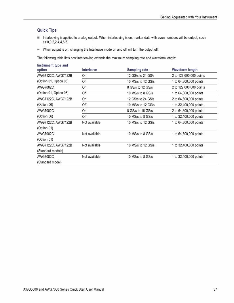
Getting Acquainted with Your Instrument
Quick TipsInterleaving is applied to analog output. When interleaving is on, marker data with even numbers will be output, suchas 0,0,2,2,4,4,6,6.
When output is on, changing the Interleave mode on and off will turn the output off.
The following table lists how interleaving extends the maximum sampling rate and waveform length:
Instrument type andoption Interleave Sampling rate Waveform length
On 12 GS/s to 24 GS/s 2 to 129,600,000 pointsAWG7122C, AWG7122B(Option 01, Option 06) Off 10 MS/s to 12 GS/s 1 to 64,800,000 points
On 8 GS/s to 12 GS/s 2 to 129,600,000 pointsAWG7082C(Option 01, Option 06) Off 10 MS/s to 8 GS/s 1 to 64,800,000 points
On 12 GS/s to 24 GS/s 2 to 64,800,000 pointsAWG7122C, AWG7122B(Option 06) Off 10 MS/s to 12 GS/s 1 to 32,400,000 points
On 8 GS/s to 16 GS/s 2 to 64,800,000 pointsAWG7082C(Option 06) Off 10 MS/s to 8 GS/s 1 to 32,400,000 pointsAWG7122C, AWG7122B(Option 01)
Not available 10 MS/s to 12 GS/s 1 to 64,800,000 points
AWG7082C(Option 01)
Not available 10 MS/s to 8 GS/s 1 to 64,800,000 points
AWG7122C, AWG7122B(Standard models)
Not available 10 MS/s to 12 GS/s 1 to 32,400,000 points
AWG7082C(Standard model)
Not available 10 MS/s to 8 GS/s 1 to 32,400,000 points
AWG5000 and AWG7000 Series Quick Start User Manual 37
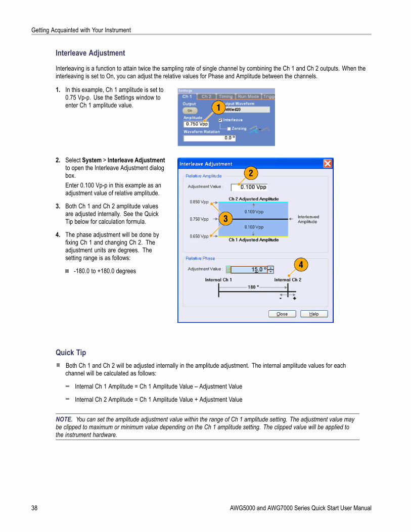
Getting Acquainted with Your Instrument
Interleave Adjustment
Interleaving is a function to attain twice the sampling rate of single channel by combining the Ch 1 and Ch 2 outputs. When theinterleaving is set to On, you can adjust the relative values for Phase and Amplitude between the channels.
1. In this example, Ch 1 amplitude is set to0.75 Vp-p. Use the Settings window toenter Ch 1 amplitude value.
2. Select System > Interleave Adjustmentto open the Interleave Adjustment dialogbox.Enter 0.100 Vp-p in this example as anadjustment value of relative amplitude.
3. Both Ch 1 and Ch 2 amplitude valuesare adjusted internally. See the QuickTip below for calculation formula.
4. The phase adjustment will be done byfixing Ch 1 and changing Ch 2. Theadjustment units are degrees. Thesetting range is as follows:
-180.0 to +180.0 degrees
Quick TipBoth Ch 1 and Ch 2 will be adjusted internally in the amplitude adjustment. The internal amplitude values for eachchannel will be calculated as follows:
Internal Ch 1 Amplitude = Ch 1 Amplitude Value – Adjustment Value
Internal Ch 2 Amplitude = Ch 1 Amplitude Value + Adjustment Value
NOTE. You can set the amplitude adjustment value within the range of Ch 1 amplitude setting. The adjustment value maybe clipped to maximum or minimum value depending on the Ch 1 amplitude setting. The clipped value will be applied tothe instrument hardware.
38 AWG5000 and AWG7000 Series Quick Start User Manual

Getting Acquainted with Your Instrument
Digital Output (Option 03)Option 03 supports digital data output on AWG5002C, AWG5012C, AWG5002B, and AWG5012B instruments.
1. The SMB connectors for 14 bit digitaldata output are present for Ch 1 andCh 2 on the rear panel.
2. You can set the output parameters asfollows:
Digital Amplitude/Offset
Digital High/LowThe digital output levels are fixed asfollows:
–1.0 V to +2.7 V, into 50 Ω
0.01 V resolution
Quick TipEach channel has independent output on and off control. When the output status of Ch n is set to On, both analogoutput and digital output are enabled.
AWG5000 and AWG7000 Series Quick Start User Manual 39

Saving and Recalling Setups
Saving and Recalling SetupsUse the File menu for basic file operations such as saving or recalling instrument setups or importing or exporting waveformdata. You can also use the File menu for standard Windows operations such as loading the most recent setup files.
File MenuThe following menu items are provided in the File menu. For a complete description of each menu command, refer tothe instrument online help system.
1. Recalls factory default setups. (Seepage 43, Default Setup.)
2. Opens a dialog box to load an instrumentsetup.
3. Saves (Overwrites) an instrument setup.
4. Saves an instrument setup assigning anew setup file name.
5. Use these commands to importwaveform data.
6. Exports waveform data to a file for usewith other applications.
7. A list of setup files you accessed recentlyis displayed here.
8. The application closes.
9. The application closes and then theinstrument shuts down.
Quick TipYou can also shut down the instrument by pushing the front-panel power button (On/Standby switch) while the applicationis running. When the power button is pushed, a dialog box asks you whether to save current setups. If you select Yes,the current setups are preserved and then the instrument will start the shutdown process.
40 AWG5000 and AWG7000 Series Quick Start User Manual

Saving and Recalling Setups
Saving an Instrument SetupUse the following steps to save an instrument setup:
1. Select File > Save File to overwritethe existing instrument setup with anupdated setup file.
2. To save the current setup to a new setupfile, select File > Save File As or pushthe front-panel Save button.
3. Select a location where you want to savethe setup.
4. Type a file name or use the default name.
5. Click Save.
Quick TipsIf a setup file contains Integer format waveform(s), the file size is reduced. For more information about waveformdata format (Real or Integer), refer to the online help.
To change the waveform format in the Waveform, Waveform List, or Settings window, you can use the WaveformProperties dialog box. (See page 57, Confirming Waveform Properties.)
AWG5000 and AWG7000 Series Quick Start User Manual 41

Saving and Recalling Setups
Recalling an Instrument SetupYou can recall an instrument setup from the File menu or from Windows Explorer.
1. Select File > Open File to open theOpen File dialog box.
2. Select a setup file.
3. Click Open.
Quick TipsThe arbitrary waveform generator uses a setup file that has an extension AWG. Only *.AWG files are displayed on theOpen File dialog box by default.
Once you recall a setup, the instrument retains the setup until you execute Save File or Save File As. If you select SaveFile after changing the instrument parameters, the instrument setup file will be automatically overwritten.
Output status including DC Output becomes Off when a setup file is recalled.
NOTE. The AWG5000 series and AWG7000 series setup files are compatible each other. However, if the parametervalue(s) of an instrument setup file are out of range, a warning message is displayed. In this case, out of range parametervalues are set to the default values.
42 AWG5000 and AWG7000 Series Quick Start User Manual

Saving and Recalling Setups
Default SetupPush the front-panel Factory Default button to recall the factory default settings.
1. To quickly return to the factory defaultsettings, push the front-panel FactoryDefault button.
2. When the instrument setups aremodified, a confirmation dialog boxappears.
3. You can also recall the factory defaultsettings from the File menu.
Changing Settings at Power-OnYou can select the instrument settings that are restored when you power on the instrument.
Select System > Preferences to display thePreferences dialog box. You can select thepower-on setups from the following:
1. Factory Default – The factory defaultsettings are always restored when theinstrument is powered on.
2. Last Used File – Restores the setupsthat were saved or recalled last time.
3. User Default File – A specified setup fileis always restored when the instrumentis powered on.
4. Click the icon to display a dialog box toselect the setup file.This icon is enabled when User DefaultFile is selected.
AWG5000 and AWG7000 Series Quick Start User Manual 43

Saving and Recalling Setups
Importing Waveform DataData import functions allow you to use waveform data created outside the arbitrary waveform generator. You can import datato create a new waveform or to replace existing waveform data.
The arbitrary waveform generator supports the following file formats:
*.AWG file created by Tektronix AWG5000 series or AWG7000 series
The following file formats created by Tektronix arbitrary waveform generators such as AWG400/500/600/700 series:
*.pat
*.seq
*.wfm
*.TFW file created by Tektronix AFG3000 series arbitrary/function generators
*.DTG file created by Tektronix DTG5000 series data timing generators
*.WFM or *.ISF file created by Tektronix TDS/DPO series oscilloscopes
Text file (*.TXT)
Refer to the online help system for more information about file import.
1. Select File > Import from File to displaythe Import from File dialog box.
2. Select the file format that you want toimport.
3. Click OK. The File Import dialog box,such as shown in step 4, is displayed.
44 AWG5000 and AWG7000 Series Quick Start User Manual

Saving and Recalling Setups
4. Select a file to import.
5. Select an import action in the Operationframe.
Set to – Select the channel and indexnumber. The imported waveformdata will be assigned to the specifiedposition.
Insert before – The importedwaveform data will be insertedbefore the specified cell of thesequence. When the run mode isnon-sequence, this parameter isdisabled.
Create only – The importedwaveform will be added to theWaveform List window.
Overwrite – Specified existingwaveform data is overwritten.
6. If the imported waveform data containsinformation on sampling rate, amplitude,or offset, you can select whether youload that information using the ChangeH/W Setup.For example, if you check the SamplingRate check box, the sampling rate will bemodified to reproduce the same signalas the imported data.
7. Click Open.When the import file format is *.AWG,*.DTG, or *.TXT, a corresponding dialogbox is displayed.When the import file format is other than*.AWG, *.DTG, or *.TXT, the selected fileis imported and the waveform name(s)are listed in the Waveform List window.
AWG5000 and AWG7000 Series Quick Start User Manual 45

Saving and Recalling Setups
8. If the file format is TektronixAWG5000 series or AWG7000 series,the AWG File Import dialog box isdisplayed.Select a waveform to import.
9. Click OK. The selected waveform isimported.You can select multiple waveforms.
10. If the file format is TektronixDTG5000 series, the DTG Filelmport dialog box is displayed.
11. Assign each bit of importedDTG5000 series block data (DTGbits) to AWG bits.
46 AWG5000 and AWG7000 Series Quick Start User Manual

Saving and Recalling Setups
12. If text file format is selected, the Text FileImport dialog box is displayed. Selectthe file format using the Format frame.Select Digital to specify each bit for DAC.If your instrument is an AWG5000 series,Digital format is fixed to 14 bits.
13. Select the normalize option using theNormalize frame.
None – The waveform data is notnormalized.
Fit to DAC range, preserve offset –The waveform data is scaled relativeto 0 (zero).
Fit to full DAC range – Minimumvalue goes to –1.0 in normalizedvalue and the maximum value goesto +1.0 in normalized value.
14. This dialog box is displayed when youexecute import and the same namewaveforms already exist. Select Yes orYes to All to replace the waveform(s).
Quick TipsWhen creating a new waveform, the name of the imported file will be the name of created waveform.
By executing the file import function, the existing waveform is changed to be the same length as the imported file.
AWG5000 and AWG7000 Series Quick Start User Manual 47

Saving and Recalling Setups
Exporting Waveform DataThe arbitrary waveform generator can export waveform data to a text file for use with other applications. You can also selecta pattern file or waveform file for use in AWG400/500/600/700 series instruments.
1. Select the waveform data for export.You can select a waveform from theWaveform List window.
2. Right click to display the popup menu.Select Export Waveform to File to openthe dialog box.You can also select the Export Waveformto File dialog box by right-clicking in theSequence or Waveform window.
3. This is an example of a dialog box whenyou export a Real format waveform in anAWG7000 series instrument.
4. Select a file format.
5. You can export a Real formatwaveform into a *.wfm file forthe AWG400/500/600/700 seriesinstruments.
48 AWG5000 and AWG7000 Series Quick Start User Manual

Saving and Recalling Setups
6. This is an example of a dialog box whenyou export an Integer format waveformin an AWG7000 series instrument.
7. You can select Analog or Digital whenyou select a *.txt format. Select Digitalto specify each bit for DAC.
8. You can export an Integer formatwaveform into a *.pat file forthe AWG400/500/600/700 seriesinstruments.
9. Click OK. The Export dialog box shownin step 10 is displayed.
10. Select a location to save the waveformdata in Save in box.
11. The waveform name you selected in theWaveform List window is displayed.
12. Click Save. You can export the selectedwaveform data as a specified file format.
Quick TipsAnalog data is exported as normalized value.
You can select DAC resolution when an Integer waveform is exported. The selected DAC resolution is used to convertinteger data to normalized value.
To change waveform format (Real or Integer), use the Waveform Properties dialog box. (See page 57, ConfirmingWaveform Properties.)
AWG5000 and AWG7000 Series Quick Start User Manual 49

Waveform Display and Edit
Waveform Display and Edit
Waveform WindowYou can use the Waveform window to edit a newly created waveform or user-defined waveform listed in the Waveform Listwindow. A selected element in the Sequence window or a selected waveform on the Ch n page of the Settings window isdisplayed in the Waveform window.
1. This is an example of Graphic display.Analog data and markers for Ch 1 andCh 2 are displayed.
2. Click this icon to toggle graphic displayand table display.
3. Click this icon (Vertical Best Fit) to adjustanalog channel height so that all theelements are contained in the Waveformwindow.
4. This is an example of Table display.You can select either Analog or Digital inthe Table display. This example showsDigital display with binary format.
Quick TipsYou can select displayed items in the Waveform window from analog data only, marker data only, or analog andmarker data.
To remove waveform data from the Waveform window, select Edit > Clear from the menu bar.
You can select the vertical and horizontal units using the Display Properties dialog box. (See page 29, Changing theWindows Display Style.)
To set a waveform from the Waveform List window, select a waveform and drag and drop it to the Waveform window.
50 AWG5000 and AWG7000 Series Quick Start User Manual

Waveform Display and Edit
Using ZoomUse Zoom when you want to temporarily look at details of a waveform. To magnify a waveform, select Zoom commands fromthe View menu, or use the Zoom icons. The choices are as follows:
1. Zoom In – Use Zoom In to magnify awaveform horizontally and vertically atthe same time.
2. Horizontal Zoom In – Use HorizontalZoom In to magnify a waveformhorizontally.
3. Vertical Zoom In – Use Vertical ZoomIn to magnify a waveform vertically.You can select the vertical scaledefinition when zooming vertically.Use the Preferences dialog box. (Seepage 28, Setting the User Preferences.)
4. Zoom Out – Use Zoom Out to return theprevious zoom factor. You can use ZoomOut only after the waveform is magnified.
5. Fit to Window – Use Fit to Window to fitthe waveform in the window and restorethe waveform to its state before the firstzoom in. You can use Fit to Window onlyafter the waveform is magnified.
6. The fastest way to set up a zoom displayis to use Zoom icons on the Waveformwindow.Select one of the Zoom icons, and thenclick and drag across the segment of thewaveform to create a box for zooming, orjust click a point in the waveform.
AWG5000 and AWG7000 Series Quick Start User Manual 51
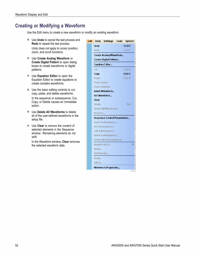
Waveform Display and Edit
Creating or Modifying a WaveformUse the Edit menu to create a new waveform or modify an existing waveform.
Use Undo to cancel the last process andRedo to repeat the last process.Undo does not apply to cursor position,zoom, and scroll functions.
Use Create Analog Waveform orCreate Digital Pattern to open dialogboxes to create waveforms or digitalpatterns.
Use Equation Editor to open theEquation Editor to create equations tocreate complex waveforms.
Use the basic editing controls to cut,copy, paste, and delete waveforms.In the sequence or subsequence, Cut,Copy, or Delete causes an immediateaction.
Use Delete All Waveforms to deleteall of the user-defined waveforms in thesetup file.
Use Clear to remove the content ofselected elements in the Sequencewindow. Remaining elements do notshift.In the Waveform window, Clear removesthe selected waveform data.
52 AWG5000 and AWG7000 Series Quick Start User Manual

Waveform Display and Edit
Creating a Standard WaveformYou can create a new waveform using the Create Analog Waveform dialog box.
1. Select Edit > Create Analog Waveformto open the Create Analog Waveformdialog box.
2. Use Function to select a waveformtype. You can select a waveform fromSine, Triangle, Square, Ramp, GaussianNoise, and DC.
3. Use Timing to set parameters forFrequency, Waveform Length, andCycle.
4. Select Auto or No Change in SamplingRate.
Auto Sampling rate and waveformlength are automatically set toappropriate values.
No Change Sampling rate is notchanged. You can select anytwo parameters from frequency,waveform length, and cycle.The remaining parameter will becalculated automatically.
5. A waveform is displayed on the Previewscreen.
AWG5000 and AWG7000 Series Quick Start User Manual 53

Waveform Display and Edit
6. Use Level to set parameters forAmplitude/Offset or High/Low.
7. Use Option to select the amplitude/offset settings. This frame is displayedwhen you set the vertical units to Voltage.If you set the vertical units to NormalizedValue, this frame is disabled. (Seepage 29, Changing the Windows DisplayStyle.)
8. Select an edit action in the Operationframe.
Set to – Specifies the channeland index number. The createdwaveform is assigned to the specifiedposition.
Insert before – The createdwaveform is inserted before thespecified cell of the sequence. Whenthis command is executed, theremaining data is shifted. When theRun mode is non-sequence, thisparameter is disabled.
Create Only – Creates a newwaveform, but the waveform is notloaded. Enter the waveform namein the Waveform Name box. Thecreated waveform is listed in theWaveform List window.
Overwrite – Specified existingwaveform data is overwritten. Whenyou select Overwrite, a waveformcurrently being loaded is displayed inthe Target Waveform Name box. TheWaveform Name box is disabled.
9. Click Execute to create a waveform.
Quick TipUse Create Digital Pattern to create digital patterns in a similar manner as creating Analog waveforms.
54 AWG5000 and AWG7000 Series Quick Start User Manual

Waveform Display and Edit
Equation EditorThe Equation Editor is an ASCII text editor that uses text strings to create waveforms by loading, editing, and compiling equationfiles. The editor provides control and flexibility to create more complex waveforms than using the Create Analog Waveform orCreate Digital Pattern tools alone. Access the editor from the Edit menu.
The following list provides some limitationsand guidelines for using the Equation Editor.
The maximum number of characters in atext string is 256, including spaces.
The maximum length (sum of all stringlengths) in a program is 1000.
The Equation Editor only supports the7-bit ASCII character set.
Concatenate strings with a colon. Anexample of embedding a numeric valuein a string is “AA”:i:”Value”.
Click the icons in the tool bar foroperations such as open, save, cut,copy, and paste.
Click the tabs to access tools to help create or modify equations:
The Soft Keypad provides an on-screen keyboard for entering data and characters directly.
Use the Basic Keywords tab to quickly enter predefined variables and control statements.
Use the Waveform Functions tab quickly enter common waveform functions.
Use the Math Functions tab to quickly enter math functions to use as part of a waveform equation expression.
Refer to the online help for additional information on the equation editor and the waveform functions.
AWG5000 and AWG7000 Series Quick Start User Manual 55

Waveform Display and Edit
Accessing Waveform in a Setup FileA created waveform is registered as a user-defined waveform in the Waveform List window. The Waveform List window lists thewaveforms that are saved in the setup files (*.awg).
1. To select a predefined waveform, clickthe Predefined tab.
2. Predefined waveforms have an asterisksign (*) to the left of the waveform name.
NOTE. You cannot edit, delete, or renamethe predefined waveforms.
3. To select a user-defined waveform, clickthe User Defined tab.To edit a user-defined waveform,select the waveform and drag it to theWaveform window.
4. You can sort the waveform list by theorder of Waveform Name, Length, orDate.
5. Each waveform length is displayed as athree-digit number in the Waveform Listwindow.
6. If you want to know the exact waveformlength, select the waveform and thenright-click to display the pop-up menu.Select Waveform Properties to displaythe Waveform Properties dialog box. Youcan confirm the waveform length withthis dialog box.
Quick TipsIf you right-click this window, a pop-up menu displays. You can access the commands, such as Delete, Copy, and Paste.
When you create a waveform, you cannot use the same name as a predefined waveform.
56 AWG5000 and AWG7000 Series Quick Start User Manual

Waveform Display and Edit
Changing a User-Defined Waveform NameYou can change a user-defined waveform name in the Waveform List window.
1. Select a waveform in the Waveform Listwindow, and then select Edit > Renamefrom the menu bar to open the Renamedialog box.
2. The waveform name is displayed.
3. Enter the new waveform name in the Tofield.
Confirming Waveform PropertiesYou can confirm or change properties of waveform data using the Waveform Properties dialog box.
1. Select a waveform in the WaveformList window, and then select WaveformProperties from the popup menu todisplay the dialog box.You can access the Waveform Propertiesdialog box by right-clicking in theWaveform window or the Ch n page ofSettings window.
2. You can confirm or change the waveformlength.
3. You can confirm or change the waveformdata type (Real or Integer).
AWG5000 and AWG7000 Series Quick Start User Manual 57
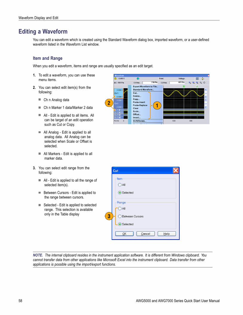
Waveform Display and Edit
Editing a WaveformYou can edit a waveform which is created using the Standard Waveform dialog box, imported waveform, or a user-definedwaveform listed in the Waveform List window.
Item and RangeWhen you edit a waveform, items and range are usually specified as an edit target.
1. To edit a waveform, you can use thesemenu items.
2. You can select edit item(s) from thefollowing:
Ch n Analog data
Ch n Marker 1 data/Marker 2 data
All - Edit is applied to all items. Allcan be target of an edit operationsuch as Cut or Copy.
All Analog - Edit is applied to allanalog data. All Analog can beselected when Scale or Offset isselected.
All Markers - Edit is applied to allmarker data.
3. You can select edit range from thefollowing:
All - Edit is applied to all the range ofselected item(s).
Between Cursors - Edit is applied tothe range between cursors.
Selected - Edit is applied to selectedrange. This selection is availableonly in the Table display
NOTE. The internal clipboard resides in the instrument application software. It is different from Windows clipboard. Youcannot transfer data from other applications like Microsoft Excel into the instrument clipboard. Data transfer from otherapplications is possible using the import/export functions.
58 AWG5000 and AWG7000 Series Quick Start User Manual

Waveform Display and Edit
Cut and Paste Example
The following procedure shows Cut and Paste example in the Waveform window (Graphic display). You can also executeCut or Paste in the Table display.
1. Select the item(s) you want to edit. Thisexample shows cut and paste operationusing two channels.
2. Specify the range using cursors.
3. Select Edit > Cut to open the Cut dialogbox. Select the following:
Item – Selected
Range – Between CursorsIf you need to change the Items or Rangesettings, use this dialog box.
4. Click OK.
5. The selected part of the waveform is cut.
NOTE. If a part of items are cut or deleted,the waveform length will not be shortened.The data is shifted. The part after the shiftedarea will be filled with default value.
NOTE. If all items are cut or deleted, thewaveform length is shortened accordingly.
AWG5000 and AWG7000 Series Quick Start User Manual 59

Waveform Display and Edit
6. Select Ch 2.
7. Specify the edit target using the cursors.From the Edit menu, select Copy.
8. This is an example of Paste-Replace.The specified range of Ch 2 waveform ispasted and replaces the Ch 1 waveform.The Ch 1 waveform length is notchanged.
9. This is an example of Paste-Insert.The specified range of Ch 2 waveformis inserted on the Ch 1 waveform. TheCh 1 waveform length is changed.
60 AWG5000 and AWG7000 Series Quick Start User Manual

Waveform Display and Edit
Math WaveformsYou can use the Math dialog box to perform mathematical operations on the waveform you are editing. The analog data oftwo waveforms can be added, subtracted, or multiplied. The created waveform data can be added to the Waveform List.
1. Select Tools > Math to display the Mathdialog box.
2. You can enter a waveform name in theNew Waveform field.
3. Select a waveform from the waveformlist. Click the icon to display theWaveform List dialog box.
4. Select a math operator.
5. (AWG7000 series) Select the resolution.
6. If you click Show Preview, thecalculation results will appear on thePreview screen.
7. Click OK to add the new waveform to theWaveform List window.
Quick TipsA new waveform will be created as the result of waveform math operation. For the marker data, the data of the firstoperand waveform will be copied to the new waveform.
The math operation is executed for all analog waveform data.
If the length of two waveforms is not the same, the length of the result is the same as the length of the shorter waveform.The beginning part of the longer waveform is used for the calculation.
AWG5000 and AWG7000 Series Quick Start User Manual 61

Waveform Display and Edit
Normalize OptionYou can select normalize options when analog data is normalized. Normalize is executed for the entire analog waveform data.
Select one of the following options from theTools menu:
1. Fit to DAC range, preserve offsetThe waveform data is scaled relative to0 (zero).
2. Fit to full DAC rangeMinimum value goes to–1.0 in normalized value andthe maximum value goes to+1.0 in normalized value.
Using Other Edit Menu CommandsScale. You can scale the specified range of analog data using Scale from the Edit menu.
1. Vertical scale origin and scale factor canbe set. The scale factor does not havethe units.
2. Use this dialog box to change the Item orRange. (See page 58, Item and Range.)
62 AWG5000 and AWG7000 Series Quick Start User Manual
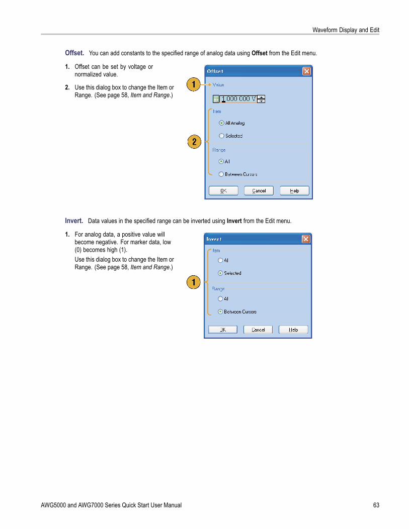
Waveform Display and Edit
Offset. You can add constants to the specified range of analog data using Offset from the Edit menu.
1. Offset can be set by voltage ornormalized value.
2. Use this dialog box to change the Item orRange. (See page 58, Item and Range.)
Invert. Data values in the specified range can be inverted using Invert from the Edit menu.
1. For analog data, a positive value willbecome negative. For marker data, low(0) becomes high (1).Use this dialog box to change the Item orRange. (See page 58, Item and Range.)
AWG5000 and AWG7000 Series Quick Start User Manual 63

Waveform Display and Edit
Horizontal Shift/Rotate. You can shift or rotate the specified range of waveform data horizontally using Shift/Rotatefrom the Edit menu.
1. Select Mode (Shift or Rotate).You can set the shift or rotate values(time or points).
2. Linear or Quadratic interpolation can beselected for fractional shift or rotation.
3. Use this dialog box to change the Item orRange. (See page 58, Item and Range.)
Quick TipsHorizontal Rotate is used to check if the waveform data is connected smoothly from the end of the first waveform to thebeginning of the second waveform. This is especially useful when the waveform is looped by the sequencer.
Horizontal Shift/Rotate is applied for analog data and marker.
64 AWG5000 and AWG7000 Series Quick Start User Manual

Waveform Display and Edit
All High/All Low. You can set the specified range of data to high or low using All High/All Low from the Edit > ModifyPattern menu.
1. Select All High or All Low.
2. Change the Level parameters, if needed.
3. Select the Item and Range.
PRBS. You can replace a specified range of data with a PRBS pattern using PRBS from the Edit > Modify Pattern menu.
1. Select a PRBS pattern from the Equationlist.
2. Select a Mark Density.
3. Change the Level parameters, if needed.
4. Select the Item and Range.
AWG5000 and AWG7000 Series Quick Start User Manual 65

Waveform Display and Edit
User Defined. You can fill the specified range of waveform data with a selected digital pattern using User Defined from theEdit > Modify Pattern menu.
1. Select Binary or Hex for the pattern.
2. Enter a pattern directly, or load a textfile from the internal hard drive or anexternal memory device.The maximum length of a bit pattern is1000 (250 Hex characters).
3. Change the Level parameters, if needed.
4. Select the Item and Range.If multiple items are specified as thetarget, the same data is created for allitems.
Clock. You can fill a specified range of data with a clock pattern using Clock from the Edit > Modify Pattern menu.
1. Select the Start Level.
2. Enter the values for Low Step and HighStep.
3. Change the Level parameters, if needed.
4. Select the Item and Range.
66 AWG5000 and AWG7000 Series Quick Start User Manual

Waveform Display and Edit
Binary Counter. You can fill the specified range of data with a binary counter pattern using Binary Counter from the Edit >Modify Pattern menu.
1. You can select the direction (Up counteror Down counter).The up counter begins from all 0, and thedown counter begins from all 1.
2. Change the Level parameters, if needed.
3. Select the Item and Range.
AWG5000 and AWG7000 Series Quick Start User Manual 67

Sequence
SequenceIt is sometimes necessary to create long waveform files to fully implement a DUT test. Where portions of the waveforms arerepeated, a waveform sequencing function can save you a lot of memory-intensive waveform programming.
Sequence is used for mainly the following two purposes:
Output longer waveform than hardware memory
Change the output waveform quickly (such as ATE applications)
NOTE. Wait Trigger is set to On in an instrument without option 08. To set Wait Trigger Off, option 08 must be installed inthe instrument.
Quick TipFor instruments with Option 09, use subsequences with sequences to create longer waveform files, rather than usingsequences alone.
Sequence WindowWhen Sequence is selected in the Run Mode, this window shows information on the status of the sequence settings. (Seepage 23, Run Mode.)
This is an example of the Sequence windowThumbnail display.
1. If you click a cell, the selected waveformis displayed in the Waveform window.The background color of the selectedcell changes.
2. If you hover the mouse over a sequencecell, a tooltip appears to show you thewaveform name and waveform length.
3. Click Switch to Table to change thedisplay to Table display.
68 AWG5000 and AWG7000 Series Quick Start User Manual

Sequence
This is an example of Table display. You candirectly enter a sequence parameter value,such as Repeat count or Go To target, in theTable display.
Quick TipsThe following methods are available for applying an existing waveform to a sequence:
Drag and drop a waveform from the Waveform List window to a cell of the Sequence window
After selecting a cell in the Sequence window, use Set Waveform or Insert Waveform from the Edit menu
When Continuous, Triggered, or Gated is selected in the Run mode, the Sequence window is hidden.
The following icons are used in the Sequence window:
Display icons DescriptionWait Trigger
Repeat. (Repeat count is set to 26 in this example.)
Repeat (Infinite)
Event Jump. (Jump target is set to index number 26 in this example.)
Go To. (Go To target is set to index number 26 in this example.)
Subsequence
AWG5000 and AWG7000 Series Quick Start User Manual 69

Sequence
Creating a SequenceTo create a sequence, waveforms must be assigned to Sequence window. The following example shows basic steps tocreate a sequence.
1. Select a waveform in the Waveform Listwindow.
2. Drag and drop the waveform to asequence window cell.As a quick access to the waveform list,you can double-click or right-click a cell.
3. After assigning waveforms to sequencecells, you can define the sequenceparameters.Right-click a cell, or use the Edit menu toopen the Sequence Control Parametersdialog box.
4. The sequencer will wait for the triggerbefore generating a waveform if WaitTrigger is checked.
5. A waveform can be repeated if theRepeat Count is specified for eachelement of the sequence.
6. Event Jump To changes the sequencingof the waveform by the external event.See the Quick Tips below for supportedevent signals.
7. If you specify Go To target for eachsequence element, the sequencerjumps to the element specified by GoTo target immediately after generatingthe waveform specified in a sequenceelement.
70 AWG5000 and AWG7000 Series Quick Start User Manual

Sequence
8. A sequence element consists of allanalog waveform data and marker datawith an index number.
9. A selected element is called currentelement.
10. A selected element in the Sequencewindow will be displayed in the Waveformwindow.
Quick TipsYou can use the Standard Waveform dialog box to create a waveform and set the waveform to Sequence window.
When importing waveform data, you can directly set the waveform to Sequence window.
If Sequence is selected in the Run mode, the sequencer executes the sequence definition. Sequence definition consistsof a series of sequence elements. Each sequence element has the following information:
References to the waveform for each channel
Sequence control parameters (Wait, Repeat, Event Jump To and Go To)
Sequence is executed in turn from the first element (Element Index = 1) to the last element. If an element has Jump To orGo To, the sequencer follows that definition.
The following signals are supported as an event:
A signal is applied to the front-panel Event Input connector
The front-panel Force Event button is pushed
Remote command is received – EVENt[:IMMediate]
Maximum sequence length is different depending on the instrument type.
Instrument type Maximum sequence lengthAWG7000 series 1 to 16,000 stepsAWG5000 series 1 to 8,000 steps
AWG5000 and AWG7000 Series Quick Start User Manual 71

Sequence
NOTE. There are two sequencer modes in the arbitrary waveform generator to execute the created sequence: the hardwaresequencer mode and the software sequencer mode. Refer to the online help for details about the difference between thehardware and software sequencer modes.
Creating a SubsequenceSubsequences are sequences that can be recalled from existing sequences. Sequences can have more than onesubsequences, but subsequences cannot have subsequences. Subsequences are available with instruments with Option 09.For more information on using subsequences, refer to the online help.
1. Select New Subsequence from thedrop-down list in the Sequence window.
2. Add waveforms as needed to the newsubsequence. (See page 70, Creating aSequence.)
3. Right-click the cell and select SequenceControl Parameters.
72 AWG5000 and AWG7000 Series Quick Start User Manual

Sequence
4. Specify the repeat count for eachsubsequence element.
NOTE. You cannot set the Repeat Count toinfinity for a subsequence element.
5. After defining all of the elements inthe subsequence, you must name thesubsequence. Right-click the mouse andselect Name Subsequence.
6. Enter a name for the new subsequence.The new subsequence is added to thelist of subsequences in the WaveformList window.
AWG5000 and AWG7000 Series Quick Start User Manual 73

Sequence
Editing a SequenceThe following commands are provided for sequence edit:
Set Waveform and Insert Waveform. Use these menus to set or insert a waveform to a Sequence window cell.
Clear. Clear removes the contents of selected element(s). You can clear multiple non-contiguous elements. Unselectedelements do not shift.
Cut and Delete. Cut and Delete can be done by the units of element. You can cut or delete multiple and continuouselements at a time.
Copy, Paste-Insert and Paste-Replace. You can copy or paste data on one or more contiguous elements. Thedata in the clipboard will be inserted or replaced at the specified position of the sequence. If Paste-Insert is executed,the existing data is shifted.
Edit Example
The following procedure shows Cut and Paste example in the Sequence window (Table display).
1. Create a sequence.
2. Select the element(s) to cut. In thisexample, Index number 3 is the targetof Cut.
NOTE. You can Cut and Delete at the unitsof element level.
74 AWG5000 and AWG7000 Series Quick Start User Manual

Sequence
3. Cut is executed and the remaining datain the sequence are shifted.
NOTE. Cut data is placed in the clipboard.Deleted data is removed from the sequenceand cannot be recovered.
4. Clear initializes the data of selectedwaveform(s) or element(s). A clearedcell becomes Empty.
5. Use Insert Waveform to insert awaveform from the Waveform List.
6. You can use Paste-Insert orPaste-Replace when you want toset a waveform after copying anywaveform in the Sequence window.
AWG5000 and AWG7000 Series Quick Start User Manual 75

Sequence
Event JumpUse the Event page of Settings window to set parameters for event signal. You can use the Event page when the Runmode is Sequence.
1. Sets external event input threshold level.
2. Selects the polarity of external eventinput signal (Positive or Negative).
Positive – Jump will occur when theinstrument receives a positive pulse.
Negative – Jump will occur when theinstrument receives a negative pulse.
3. Sets jump timing (Async or Sync).
Async – Jump will occur immediately.
Sync – Jump will occur after thewaveform is generated.
4. Sets event input impedance (1 kΩ or50 Ω).
Quick TipsEvent Jump can change the sequence order using an event signal.
Jump timing is applied to both Event Jump and Force Jump.
76 AWG5000 and AWG7000 Series Quick Start User Manual

Sequence
Force Jump ToForce Jump allows you to jump to a position that you choose while the instrument is outputting a sequence.
Select System > Force Jump To to openthe Force Jump To dialog box.
1. Specify a jump target or select Index No.
2. When Index No is selected as jumptarget, enter the index number using theValue: field.
3. Click Jump Now to change the waveformoutput to the position specified by jumptarget.
Quick TipsThe arbitrary waveform generator has an Event Jump function which changes the sequence using an event signal. Usethe Event page of the Settings window to set parameters for Event Jump.
Force Jump is similar to Event Jump. In the case of Force Jump, you must specify the jump target explicitly by using theForce Jump To dialog box.
Force Jump is independent from Event Jump. Force Jump can be executed regardless of the Event Jump setting.
AWG5000 and AWG7000 Series Quick Start User Manual 77
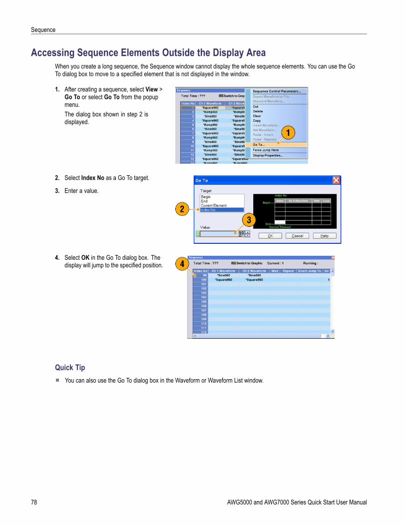
Sequence
Accessing Sequence Elements Outside the Display AreaWhen you create a long sequence, the Sequence window cannot display the whole sequence elements. You can use the GoTo dialog box to move to a specified element that is not displayed in the window.
1. After creating a sequence, select View >Go To or select Go To from the popupmenu.The dialog box shown in step 2 isdisplayed.
2. Select Index No as a Go To target.
3. Enter a value.
4. Select OK in the Go To dialog box. Thedisplay will jump to the specified position.
Quick TipYou can also use the Go To dialog box in the Waveform or Waveform List window.
78 AWG5000 and AWG7000 Series Quick Start User Manual

Tutorials
TutorialsThe examples in this section show how to use your instrument to do common arbitrary waveform generator tasks. Theseexamples use the dual-channel model.
Creating and Editing a Waveform1. Recall the default setup.
2. Select Continuous from the Run Modepage of the Settings window.
3. Use the Standard Waveform dialog boxto create the following square waveform:
Waveform Length: 960 points
Cycles: 5
Amplitude: 1.0 Vp-p
Offset: 0.5 V
4. Set the waveform created in step 3 toCh 1.
5. Assign the waveform name “Ch1-Square”to the waveform.
AWG5000 and AWG7000 Series Quick Start User Manual 79

Tutorials
6. Use the Standard Waveform dialogbox to create the sine waveform shownbelow:
Waveform Length: 1024 points
Cycles: 3
Amplitude: 1.0 Vp-p
Offset: –0.5 V
7. Set the waveform created in step 6 toCh 2.
8. Assign the waveform name “Ch2-Sine”to the waveform.
9. To edit analog waveform data, hide theCh 1 and Ch 2 Marker data using theDisplay Properties dialog box.
10. Delete points from the end of the Ch 2waveform to make it the same length asthe Ch 1 waveform.Use cursors to set the range.
Position the cursors as shown.
Select the Ch 2 waveform.
Right-click and select: Delete,Selected, Between Cursors.
Click OK.
80 AWG5000 and AWG7000 Series Quick Start User Manual

Tutorials
11. Ch 1 and Ch 2 waveforms have thesame waveform length. You can nowoutput the signal.
12. Save the setup.
Creating and Editing a Sequence1. Recall the default setup.
2. Select Sequence from the Run Modepage of the Settings window.
AWG5000 and AWG7000 Series Quick Start User Manual 81

Tutorials
3. Select *Sine960 from the Predefinedpage of the Waveform List window,and drag and drop it to the first cell ofCh 1 sequence.
4. Similarly, select *Triangle960 fromthe Waveform List window, and setthe waveform to the second cell ofCh 1 sequence.
5. Create a sine waveform with the followingattributes and set the waveform to thethird cell of Ch 1 sequence.
Waveform Length: 960 points
Cycles: 5
Amplitude: 1.0 Vp-p
Offset: 0.0 V
Waveform Name: Sine-1
6. Select third cell of sequence, and selectCopy from the popup menu.
7. Select second cell of sequence, andselect Paste-Insert from the popupmenu.
82 AWG5000 and AWG7000 Series Quick Start User Manual

Tutorials
8. The copied waveform is pasted toindex 2.
9. Click the Switch to Table icon to changethe display to Tabular view.
10. Set the following sequence parameters:
Index 1: Wait Trigger OnThe sequence waits for a triggerbefore generating the first element.
Index 2: Repeat count InfiniteThe sequence infinitely generatesthe Sine-1 waveform until an eventoccurs.
Index 2: Event Jump To NextWhen the instrument receives anevent signal, the sequence jumps tonext element.
Index 3: Repeat count 1000The sequence repeats the*Triangle960 waveform 1000times.
Index 4: Go To 1The sequence jumps to indexnumber 1 after generating indexnumber 4 waveform.
11. Click the Run button to confirm that thesequence works properly. The animationwindow next to the Run button will beactivated when the instrument is in therunning state.
AWG5000 and AWG7000 Series Quick Start User Manual 83

Tutorials
84 AWG5000 and AWG7000 Series Quick Start User Manual

Index
Index
Symbols and Numbers10 MHz Reference Output
Rear panel, 15, 17
AAccessing control windows, 24Accessing menus, 24Accessories, 1Add Input
Rear panel, 17All High/All Low
Edit menu > Modify Pattern, 65All Outputs On/Off button
Front panel, 30Status bar, 27
Analog Output connectorFront panel, 13
Arbitrary waveform generatorBasic steps, 22
BBinary Counter
Edit menu > Modify Pattern, 67
CCalibration, 8Channel Coupling
Settings menu, 35Channel page
Settings window, 32Channel Skew
System menu, 36Cleaning, 3Clear
Sequence window, 74, 75Waveform window, 50
Clock PatternEdit menu > Modify Pattern, 66
Configuration Utility dialog box, 6Continuous
Run mode, 23Control panel, 18Control settings
How to change, 25Control windows
Display/Hide, 26
Create Analog waveformEdit menu, 53
Creating OS restore discs, 11Current element, 71Cut example
Waveform window, 59
DDAC Resolution
Export waveform data, 49Settings window, 32
DC Output connectorFront panel, 13
DC Output pageSettings window, 33
Default setup, 43Diagnostics, 7Digital output, 39Direct Output, Settings window, 33Display Properties dialog box, 29Divider Rate, 34Documentation, xDynamic Jump In Connector, 15
EEdit example
Sequence window, 74Edit menu
Modify Pattern > All High/AllLow, 65
Modify Pattern > BinaryCounter, 67
Modify Pattern > Clock, 66Modify Pattern > PRBS, 65Modify Pattern > User
Defined, 66Overview, 52Sequence, 74
Element, Sequence, 71Environmental requirements, 2Equation Editor, 55Event Input connector
Front panel, 13, 71Event Jump, 77Event Jump To
Sequence controlparameter, 70
Event pageSettings window, 76
Export waveform data, 48External Clock Input
Rear panel, 15, 17
FFactory Default
Startup setting, 43File menu
Overview, 40Force Event button
Front panel, 71Status bar, 27
Force Jump ToSystem menu, 77
Force Trigger buttonStatus bar, 27
Front panel, 13Front panel controls
Lock/unlock, 19
GGated
Run mode, 23Go To
Sequence controlparameter, 70
Go To dialog boxView menu, 78
GPIB connectorRear panel, 14, 16
GPIB/LAN ConfigurationSystem menu, 5
Graphic displayWaveform window, 50
HHardware sequencer, 71Hold
Preferences dialog box, 28Horizontal units
Waveform window, 29, 50
AWG5000 and AWG7000 Series Quick Start User Manual 85

Index
IIcons
Sequence window, 69Zoom, 51
Import waveform data, 44AWG file format, 46DTG file format, 46Text file format, 47
Incoming inspection, 7Insert Waveform
Sequence window, 74Integer
Waveform format, 41, 49Integer format
Export waveform data, 49Interleave adjustment
System menu, 38Interleave Output connector
Front panel, 13Interleaving, 36, 38Invert
Edit menu, 63Item, Edit menu, 58
LLAN connector
Rear panel, 14, 16Last Used File
Startup setting, 43LCD Brightness
Preferences dialog box, 28Lock/unlock
Front panel controls, 19
MMarker output
With interleave on, 37Marker Output connector
Front panel, 13Math
Tools menu, 61Maximum sequence length, 71Menu bar
Screen interface, 21Multiplier Rate, 34
NNetwork connection, 5Normalize
Tools menu, 62
OOffline mode, 6Offset
Edit menu, 63Operating requirements, 2Option Installation
System menu, 10OS restore discs, 11, 12Oscillator Output
Rear panel, 17Output on/off, 30Overheat protection, 9
PPaste-Insert
Sequence window, 74Waveform window, 60
Paste-ReplaceSequence window, 74Waveform window, 60
Pop-up keypad, 25Power supply, 2Power-on self test, 7Power-on settings, 43PRBS
Edit menu > Modify Pattern, 65Predefined waveforms
Waveform List window, 56Preferences dialog box, 28
RRange, Edit menu, 58Raw Socket
GPIB/LAN Configuration, 5Real
Waveform format, 41, 49Real format
Export waveform data, 48Rear panel
AWG5000C series, 16AWG7000C series, 14
Recalling instrument setup, 42Reference Clock Input
Rear panel, 15, 17Remote command bar
Screen interface, 21Remote Command Log
Preferences dialog box, 28Remote PC
Controlling the instrument, 6
RenameEdit menu, 57
RepeatSequence control
parameter, 70Repetition Rate, 34Restore Operating System, 11Run button
Front panel, 30Status bar, 27
Run Mode pageSettings window, 23
Run state control, 30
SSafety Summary, iiiSaving instrument setup, 41Scale
Edit menu, 62Screen interface, 21Self calibration, 8Sequence
Edit menu, 68Run mode, 23Subsequences, 68Tutorials, 81
Sequence Control Parameters dialogbox, 70
Sequence definition, 71Sequence element, 71Sequence length, 71Sequence window, 68
Screen interface, 21Set Pattern
Edit menu > Modify Pattern, 66Set Waveform
Sequence menu, 70Sequence window, 74
Settings windowScreen interface, 21
Shift/RotateEdit menu, 64
Software sequencer, 71Standard accessories, 1Standard waveform
Tutorials, 79Status bar, 27
Screen interface, 21Subsequence
creating, 72Subsequences, 68
86 AWG5000 and AWG7000 Series Quick Start User Manual

Index
TTable display
Sequence window, 69Waveform window, 50
TekLink connectorRear panel, 14, 16
Thumbnail displaySequence window, 68
Timing pageSettings window, 34
Touch screen, 20Trigger Input connector
Front panel, 13Trigger page
Settings window, 23Triggered
Run mode, 23Tutorials
Sequence, 81Standard waveform, 79
UUSB connector
Front panel, 13Rear panel, 14, 16
User Default FileStartup setting, 43
User PreferencesSystem menu, 28
User-defined waveformsTo change name, 57Waveform List window, 56
VVertical units
Waveform window, 29, 50VXI-11 Server
GPIB/LAN Configuration, 5
WWait Trigger
Sequence controlparameter, 70
Waveform dataExport, 48Import, 44
Waveform data formatSaving an instrument setup, 41Waveform properties, 57
Waveform lengthTo change, 57
Waveform List window, 56Screen interface, 21
Waveform nameTo change, 57
Waveform PropertiesConfirming waveform
length, 56Edit menu, 57
Waveform RotationSettings Window, 32
Waveform window, 50Screen interface, 21
Window tagDisplaying and hiding control
windows, 26Screen interface, 21
ZZeroing, 36Zoom, 51
AWG5000 and AWG7000 Series Quick Start User Manual 87
Copyright © 2022 FDOKUMEN