Sawtooth First Phase Biphasic Defibrillation Waveform.: A Comparison with Standard Waveform in...
13
517 Sawtooth First Phase Biphasic Defibrillation Waveform: A Comparison with Standard Waveform in Clinical Devices YOSHIO YAMANOUCHI. M.D., JAMES E. BREWER, M.S.,* KENT A. MOWREY, M.S., MARK W. KROLL, PH.D.,** ANN M. DONOHOO, M.S.,1 BRUCE L. WILKOEF, M.D., and PATRICK J. TCHOU, M.D. From the Department of Cardiology, Cleveland Clinic Foundation. Cleveland, Ohio: and Angeion Corporation, Plymouth, Minnesota "Sawtooth First Phase" Biphasic Waveform, introduction: A major limitation in a conventional truncated exponential waveform is the rapid drop in current thai results in short duration of high current or longer duration with a lower average current. We hypothesized that increasing the first phase average current hy hoosting the decaying waveform prior to phase reversal may improve denbrillation efficacy. Methods and Results: To better simulate a "rectangular" waveform during the first phase, a "sawtooth" defihrillation waveform was constructed using "parallel-series" switching of capac- itances (each 30 fiF) during the first phase. This permitted a hoost in the voltage late in the first phase. This sawtooth hiphasic waveform (sawtooth) was compared to two clinical waveforms: a l35-y:iF capacitance (control-1) and a 90-/iF capacitance (control-2t waveform. Defihrillation threshold (DFT) parameters were evaluated in 13 anesthetized pig models using a system con- sisting of a transvenous right ventricular apex lead (anode) and a left pectoral "hot can" elec- trode (cathode) system. DFT was determined by a "down-up down-up" protocol. The stored energy for sawtooth, control-1, and control-2 was 10.5 ± 2.8 J, 12.3 ± 3.7 J*, and 12.2 ± 2.8 J*, respectively (*P < 0.01 vs sawtooth). The average current of the first phase for sawtooth, con- trol-1, and control-2 was 7.6 ± 1.3 A, 4.7 ± 0.9 A*, and 6.2 ± 0.9 A*, respectively (*P = 0.0001 vs sawtooth). Conclusion: A sawtooth biphasic waveform utilizing a "parallel-series" switching system of smaller capacitors can improve defibrillation efficacy. A higher average current in the first phase generated by such a waveform may contribute to more efficient defibrillation by facili- tating myocyte capture. (J Cardiovasc Electrophysiol, Vol. 8, pp. 517-528, May 1997) defibrillation. average current, sawtooth first phase, small capacitor, "parallel-series" switching This work was supported in part by the Angeion Corporation. Current affiliations: *Survivalink Corporation. Minneapolis. Min- nesota: **PaL-esetter Inc.. Sylmar, California; tAngeion Corpora- iion, Plyinouih. Minnesota. Address tor correspondence: Patrick J. Tchoii. M.D., Director, Clinical Cardiac Electrophysiology. The Department of Cardiol- ogy/F15. Cleveland Clinic Foundation. 9500 Euclid Ave.. Cleve- land. OH 44195. Fax: 216-445-3595; E-mail: tchoup@eesnitp. ccf.org Manuscript received 18 October 1996; Accepted for publication 29 January 1997, Introduction Deftbrillalion can be achieved by attaining an adequate cttn^nt density through a sufficient mass of the tnyocardium for an adequate titne.' The av- erage current of a monophasic pulse of 2 to 20 tnsec in duration appears to predict defibrillation efficacy for given pulse duration.- Biphasic waveforms generally require less volt- age and energy for internal ventricular deftbrilla- tion than monophasic waveforms of similar dura-
-
Upload
spanalumni -
Category
Documents
-
view
0 -
download
0
Transcript of Sawtooth First Phase Biphasic Defibrillation Waveform.: A Comparison with Standard Waveform in...

517
Sawtooth First Phase Biphasic Defibrillation Waveform:A Comparison with Standard Waveform in Clinical Devices
YOSHIO YAMANOUCHI. M.D., JAMES E. BREWER, M.S.,*KENT A. MOWREY, M.S., MARK W. KROLL, PH.D.,**
ANN M. DONOHOO, M.S.,1 BRUCE L. WILKOEF, M.D.,and PATRICK J. TCHOU, M.D.
From the Department of Cardiology, Cleveland Clinic Foundation. Cleveland, Ohio:and Angeion Corporation, Plymouth, Minnesota
"Sawtooth First Phase" Biphasic Waveform, introduction: A major limitation in aconventional truncated exponential waveform is the rapid drop in current thai results in shortduration of high current or longer duration with a lower average current. We hypothesizedthat increasing the first phase average current hy hoosting the decaying waveform prior tophase reversal may improve denbrillation efficacy.
Methods and Results: To better simulate a "rectangular" waveform during the first phase, a"sawtooth" defihrillation waveform was constructed using "parallel-series" switching of capac-itances (each 30 fiF) during the first phase. This permitted a hoost in the voltage late in the firstphase. This sawtooth hiphasic waveform (sawtooth) was compared to two clinical waveforms: al35-y:iF capacitance (control-1) and a 90-/iF capacitance (control-2t waveform. Defihrillationthreshold (DFT) parameters were evaluated in 13 anesthetized pig models using a system con-sisting of a transvenous right ventricular apex lead (anode) and a left pectoral "hot can" elec-trode (cathode) system. DFT was determined by a "down-up down-up" protocol. The storedenergy for sawtooth, control-1, and control-2 was 10.5 ± 2.8 J, 12.3 ± 3.7 J*, and 12.2 ± 2.8 J*,respectively (*P < 0.01 vs sawtooth). The average current of the first phase for sawtooth, con-trol-1, and control-2 was 7.6 ± 1.3 A, 4.7 ± 0.9 A*, and 6.2 ± 0.9 A*, respectively (*P = 0.0001 vssawtooth).
Conclusion: A sawtooth biphasic waveform utilizing a "parallel-series" switching system ofsmaller capacitors can improve defibrillation efficacy. A higher average current in the firstphase generated by such a waveform may contribute to more efficient defibrillation by facili-tating myocyte capture. (J Cardiovasc Electrophysiol, Vol. 8, pp. 517-528, May 1997)
defibrillation. average current, sawtooth first phase, small capacitor, "parallel-series" switching
This work was supported in part by the Angeion Corporation.
Current affiliations: *Survivalink Corporation. Minneapolis. Min-nesota: **PaL-esetter Inc.. Sylmar, California; tAngeion Corpora-iion, Plyinouih. Minnesota.
Address tor correspondence: Patrick J. Tchoii. M.D., Director,Clinical Cardiac Electrophysiology. The Department of Cardiol-ogy/F15. Cleveland Clinic Foundation. 9500 Euclid Ave.. Cleve-land. OH 44195. Fax: 216-445-3595; E-mail: [email protected]
Manuscript received 18 October 1996; Accepted for publication29 January 1997,
Introduction
Deftbrillalion can be achieved by attaining anadequate cttn^nt density through a sufficient massof the tnyocardium for an adequate titne.' The av-erage current of a monophasic pulse of 2 to 20tnsec in duration appears to predict defibrillationefficacy for given pulse duration.-
Biphasic waveforms generally require less volt-age and energy for internal ventricular deftbrilla-tion than monophasic waveforms of similar dura-
518 Journal of Cardiovascular Electrophysiotogy Vol. 8. No. 5. May 1997
tion. »* Several theories have been proposed to ex-plain the improvement of defibrillation by bipha-sic wavefomis.'"" One recent theoiy" suggests thatthe effectiveness of the single capacitor biphasicwaveform may be explained by the second phase"burping" of the deleterious residual charge re-iniiining on the cell membranes fix>iti the first phase.Furthermore, this theory suggested that optimiza-tion of the first phase of a bipbasic waveformshould be identical to that of a monophasic wave-fonn.
For engineering reasons, the waveform that cur-rently appears most appealing for impiantable de-vices is the truncated exponential waveform. Thelimitation of this waveform is that it has a largedrop in cuiTent during the impulse delivery, thusreducing the average current of the pulse. A saw-tooth wavefonn is a shock pulse with an abruptincrease in voltage combined witb a similarly abniptdrop in capacitance during the tlrsl pha.se of its de-livery. Tbese abrupt chjuiges in the waveform com-prise the sawtooth. A sawtooth, placed into tbe firstphase, increases the average current of the pulse.
Tbe charge burping theory hypothesizes that anoptimal pulse duration for the second phase is tbatduration which minimizes a cell's residual mem-brane potential for those eells not depolarized orhave its refractory period significantly prolongedby the first phase. Ideally, these cells are set backto "relative cell membrane ground."
The study objective was to test a biphasic wave-form designed to enhance its defibrillation abilityby adding a sawtooth to tbe first phase to maxi-mize the etfeetive current and by applying a sec-ond phase designed to charge burp those cells notaffected by the sawtoothed first phase.
Methods
Experimental Preparations and Instrumentation
Seventeen pigs (body weights 38.7 ± 5.9 kg;heart weights 163 ± 15 g) were anesthetized withsodium pentob:irbital (30 mg/kg IV), ketamine (20mg/kg IM), and morphine (2 mg/kg IM). intubatedwith a cuffed endotracheal tube, iind ventilated withroom air iind oxygen though a Drager SAV (NorthAmerican Drager. Telford, PA, USA). Infusion ofsodium pentobarbital (1 to 2 mg/kg) and pan-curonium bromide ((). I to 0.2 mg/kg) was rei eatedas necessary to maintain anesthesia and muscle re-laxation, respectively. An intra-arterial line was in-serted via a cutdown to the left carotid artery forcontinuous systemic blood pressure monitoring as
well as blood gas sampling. An intravenous linewas also inserted via a cutdown in tbe left inter-nal jugular vein for continuous infusion of nomialsaline solution. Surface leads (I, II, aVR. and V,)and the intracardiac ECG from the shockingelectrodes were continuously displayed on an ECGmonitor and selectively stored on a computer-basedphysiologic recording system (EP Lah. QuintonElectrophysiology Corporation, Botbcll. WA. USA).Arterial blood samples were drawn every 30 to fiOminutes to detemiine pH. pO,. pCO , base excess,total CO, content, and bicarbonate, stxlium, ptitas-sium. and calcium concentrations. Body tempera-ture was continuously monitored witli a ivctal ther-mistor and maintained between 36.0° and 37.0°Cby heating the lable with a warm circulating wa-ter blanket (Sitrn.s, Inc., Ann Arbor. Ml. USA). Adefibrillation electrode (model 4(X)7L. AngeionCoqxKation. Minneapolis. MN. USA) having a 4-cm-long distal electr(xle witb a 6.5-French diam-eter (surface area of 2.1 em ) was inserted underfluoroscopic guidance via culdown to the right in-ternal jugular vein into the right venlricular apex.A 55-em- titanium "hot can" electrode (AngeionCorporation) having a conductive surface area of92 em- was implanted in ihe left pectoral area.
Defibrillation Protocol
The defibrillation electrode at the right ven-tricuUu- apex and tbe subcutaneous "hot can" elec-trode were connected to the external waveformamplifier and defibrillator (Angeion Research De-fibrillation System, ARD-9(KK).'= Angeion Coipo-ration). The ARD-9(XX) operates as a high-voltage,linear amplifier utilizing software-generated wave-forms. This device sampled the current and volt-age every 0.1 msec and adjusted the waveformvoltage to mimic a capacitive discharge. Thecontinuous voltage adjustment accounted for theimpedance chiinges that occur as a functitin of volt-age changing during a dischai ge.' Preliminary testsin a saline batli demonstrated thai the voltage wave-forms generated by tbis device had < 3% varia-tion from waveforms generated by a true capaci-tor discharge in the range of 100 lo 150 V. TheARD-9000 continuously calculates the instanta-neous impedance by dividing the voltage by ihecurrent. Tlie median of all tbese values is then usedas the overall shock impedance.
Ventricular fibrillation was induced wilh 60-Hzaltemating current (8 to 10 V) for 4 seconds thrtiughthe right ventiicular distal defibrillation electrode.After sustained ventricular fibrillation lasting 10

Yamanouchi. et al. "Sawtooth First Phase" Biphasic Waveform 519
seconds from initiation of the altemating current,one of three different types of biphasic waveforms(Fig. I) was delivered. The right venlricular distaldefibrillation electrode was tbe anode for the firstphase then the catbode for the second phase. Tbeorder in wbicb the three waveforms were testedwas randomized in each pig. If ventricular fibril-lation was not terminated by one of these defi-brillation waveforms (Fig. 1), a rescue shock(monophasic 5-msec square waveform. 20 to 50 J)was delivered to terminate the ventricular fibrilla-tion witb tbe same electrode system. A recoveryperitxl of at least 3 minutes was allowed betweeneach episode of fibrillation. Fibrillation was notreinitiated until beart rate and blood pressure re-turned to preshock levels and were stable.
Defibrillation Waveforms
Control-1 waveform
.l2Vi
Control-2 wavefonn
Vi
.56V l:
V2l
Vit^ 2.5m5
Controt-J waveform
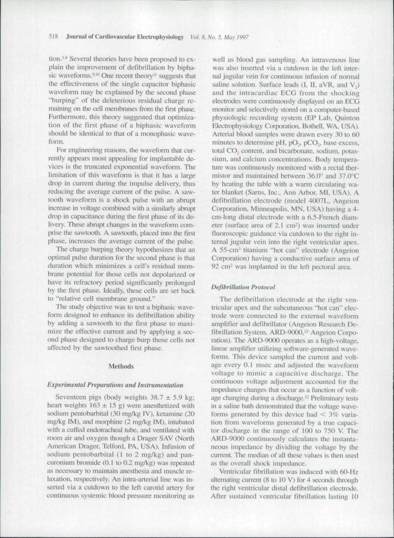
A simulated 135~/iF capacitance is dischargedto 35% of initial voltage (65% tilt) in tlie first phase.At this point., the wavefonn is inverted and tbe ca-pacitor is discharged to 35% of the remaining volt-age (65% tilt) in the second phase.
Cot}trol-2 wavefonn
A simulated 90-jjF capacitance is discharged to56% of initial voltage (44% tilt). The capacitor isfurther discharged for 1.6 ms. At tbis point, thewaveform is inverted and the capacitor is dischargedfor 2.5 msec.
Sawtooth waveform
The sawtooth wavefonn was developed usingthe effective current theory"'^ for the design oftbe first phase and charge burping theory for thedesign of tbe second phase." ' This wavefonn wasdesigned to maximize the effective current a shockpulse delivers during the first phase. Effective cur-rent is a cbronaxie-adjusted average current thatmeasures the ability of an impiantable device todefibrillate according to tbe Weiss-Lapicque hy-perbolic strength-duration model. To achieve thiswaveform, two simulated 30-/JF capacitances inparallel (equal to a single 60-fjF capacitor) are dis-charged during tbe initial portion of the first phase.At tbe point which maximized tbe "effective cur-rent" for the pulse duration in the initial portion ofthe first phase, the capacitors are switched to se-ries (equal to a single 15-/JF capacitor) and further
Sawtooth wavefonn
Vi\
.49V1
. 3.5ms .
Figure 1. Diagram of each hiphasie waveform. The con-trol-1 waveform: A 135-fjF capacitance is discharged to35% of initial voltage (65% tilt in first phase). At this point,the wavefonn is inverted and ihe capacitance i.s dischargedto 35% of the remaining voltage (65% tilt in second pimse).The control-2 waveform: A 9O'fiF capacitance is dis-charged to 56% of initiai voltage (44% tilt). The capaci-tance is further discharged for 1.6 ms. At this point, tiiewaveform is inverted and the capacitance is discharged for2.5 msec. The sawtooth waveform: Two 30-fjF capaci-tances in parallel (equal to a single 6O-/1F capacitor) aredischarged during the initial portion of tite first phase. Atthe point that maximized the "effective current" for thepulse duration in the initial portion of the first phase, thecapacitors are switched to series iequal to a single 15'//Fcapacitor) and further discharged. In addition, at the pointthat the first phase duration is calculated to optimize this"effective current." the waveform is inverted. A .separate,single .iO-/xF capacitor is discharged for 3.5 msfor the sec-ond piiase.
discharged. Tbe "effective eurrent" has been de-fined as tbe waveform's average current normal-ized by the pulse duration."" In addition, at thepoint which the first phase duration is calculatedto optimize tbis "effective current," the wave-
520 Journal of Cardiovascular Electrophysiology Vol. S. No. 5. May 1997
form is inverted. A separate, single simulated 30-fjF capacitor is discharged for 3.5 msec for thesecond pha.se (Fig. I). Specific design considera-tions of this sawtooth wavefonn are detailed in theAppendix.
Calculation of Average Current and EffectiveCurrent
The ARD-9000 measures the current everyO.i msec in each wavefonn. The average currentof the first phase was calculated as the sum of allsampled current values divided by the number ofsamples. The effective current is defined as the av-erage current divided by (1 -t- d^d). where d . is thechronaxie duration (2.7 msec assumed"'-') and dis the pulse width.
Determination of Defibrillation Threshold
A stored energy of 15 to 20 J was used for tbeinitial defibrillation trial of each wavefonn in eachpig. If an initial maximum shock of 20 J failed todefibrillate, the electrode at the right ventricularapex was repositioned until there was a success-ful shock of 20 J. Defibrillation threshold (DFT)was detemiined by a "down-up down-up" tecb-nique until three reversals of defibrillation successwere completed as described pix^viously.'^"' Briefiy.after the initial successful shtxrk, the stored energywas decremented by I J following each success-ful defibrillation. When a shtx'k failed to defibril-late. the next trial was pertbnned by incrementingthe stored energy by ! J. Tbis process was repeateduntil three reversals in decrement or increment cx:-curred. The final shock was always a success fol-lowing tbe last failure. The DFT was defined asthe average of the shock energy or voltage valuesobtained with all trials, starting from the success-ful shock prior to the first defibrillation failure tothe last successful defibrillation.
After determination of the DFTs for tbe threewaveforms, prepiiration .stability was ensured by re-peating the DFT energy measurements for the firstof the randomized waveforms tested in that animal.If this DFT energy was within 2 J of the first DFTenergy, then the preparation was deemed stable andthe experiment was included in the study. If therewas a change > 2 J between tbe first DFT energyand this last DFT energy, tbe preparation was notconsidered stable, and the data were rejected.
After completing tbe protocols, tbe pig was eu-thanized by electrically induced ventricular fibril-lation. The heart was excised and weighed.
Statistical Analysis
mean and SD of all parameters were cal-culated for each of the three waveforms usinggrouped data from 13 animals. Repealed measureANOVA was used to compare stored enei^y, de-livered energy, peak voltage, peak current, aver-age current, and median impedance among thethree defibrillation wavefomis. Pairwise compar-i.sons of waveform were made for each parameter,using contrasts.!^ The null hypothesis was rejectedfor P < 0.05.
Results
We obtained complete DFT datasets from 13pigs. We rejected test data from four pigs due tounstable defibrillation environments. The DFT pa-rameters and pulse width for each waveform aredetailed in Table I. The average number of shtx'ksutilized to calculate the DFT for each of ihc threewavefonns was 7.4 ± 2.2 for the control-1. 7.5i ±2.2 for the controI-2. and 8.9 ± 3.4 for the saw-tooth wavefonn.
Energy
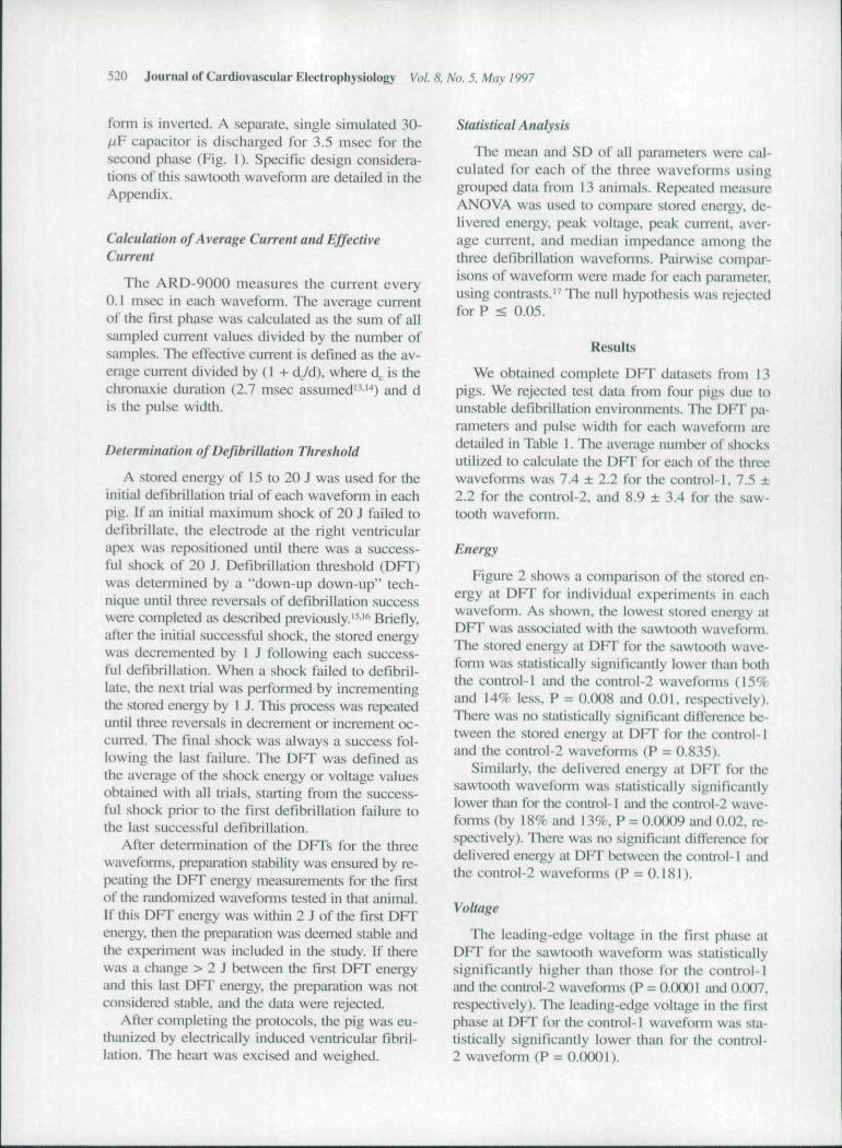
Figure 2 shows a comparison of the stored en-ergy at DFT for individual experiments in eachwaveform. As shown, the lowest stored energy atDFT was asscx'iated with the sawtooth waveform,Tbe stored energy at DFT for the sawtotrth wave-form was statistically significantly lower than boththe control-1 and the control-2 wavefonns (15%and 14% less, P = 0.008 and 0.01, respectively).There was no statistically significant ditference be-tween the stored energy at DFT for the control-1and the control-2 wavefonns (P = 0.835).
Similarly, the delivered energy at DFT for thesawtooth waveform was statistically significantlylower than for the contix>l-1 and the controI-2 wave-forms (by 18% and 13%, P = O.(XK)9 and 0.02, re-spectively). There was no significant dilTerence fordelivered energy at DFT between the control-1 andthe control-2 waveforms (P = 0.I8I).
Voltage
Tbe leading-edge voltage in the first phase atDFT for the sawtooth wavefonn was statisticallysignificantly higher than those for the control-1and Ihe C()nti-ol-2 wavefonns (P ^ ().(XK)1 iind O.(X)7.respectively). Tbe leading-edge voltage in the firstphase at DFT for the control-1 waveform was sta-tistically significantly lower thiui for tlie control-2 wavefonn (P = 0.0001).

Yamanouchi, etal. "Sawtooth First Phase" Biphasic Waveform 521
Similarly, the leading-edge voltage in the sec-ond phase at DFT for the sawtooth waveform wasstatistically significantly higher than both the con-trol-1 and the control-2 waveforms (P = 0.0001and O.{X)OI. respectively). The leading-edge volt-age in the second phase at DFT for the control-1wavefonn was statistically significantly lower thanthe control-2 waveform (P = 0.0001).
Peak.. Average, and Effective Currents
The peak current in the first phase at DFT forthe sawtooth wavefonn was higher than the con-trol-1 and the control-2 waveforms (P = 0.0001and 0.007, respectively). The peak current in thefirst phase at DFT for the control-1 wavefonn waslower than the control-2 waveform (P = 0.0001).
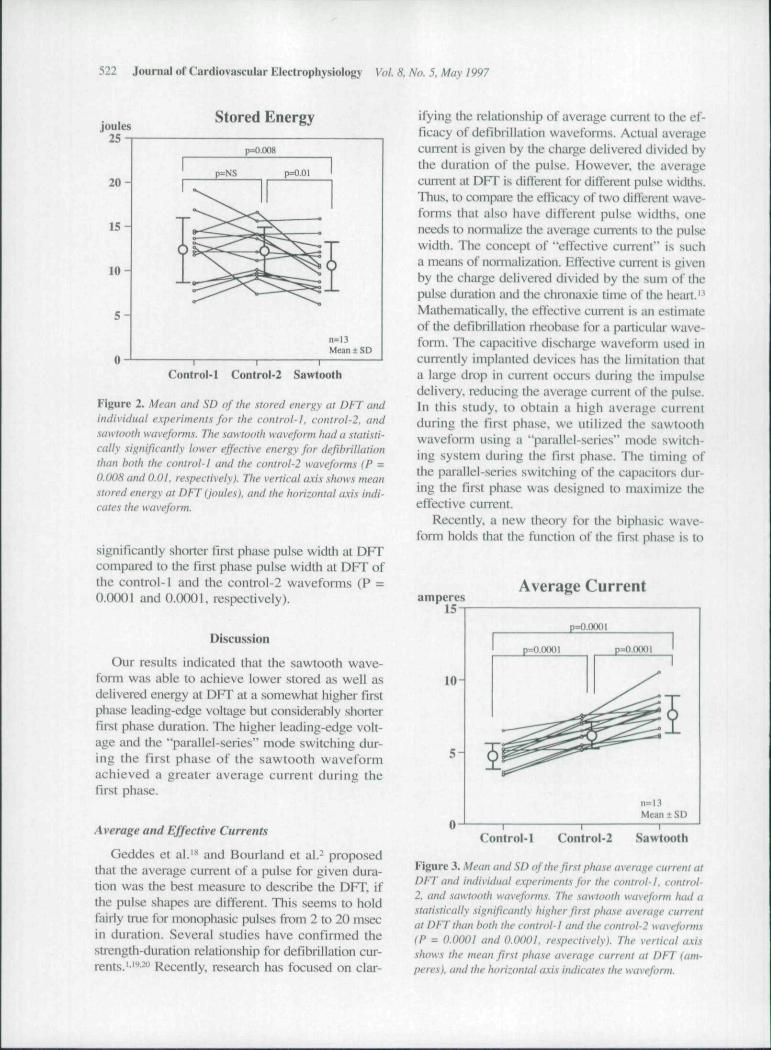
Figure 3 shows a comparison of the averagecurrent in the first phase at DFT for individual ex-periments in each wavefonn. The average currentin the first phase at DFT for the sawtooth wave-form was significantly higher than the control-1and the control-2 wavefonns (62% and 23%, P =0.0001 and 0.0001, respectively). On the otherhand, the effective current (3.9 ± 0.5 A) in the firstphase at DFT for the controI-2 was statisticallyhigher as compared to the control-1 (3.5 ± 0.7 A.p = 0.0009) and the sawtooth (3.3 ± 0.5 A, P =O.O(M)I) wavefonns. There was no significant dif-ference between the control-f and the sawtoothwaveforms (P = 0.0674). However, the differencein the effective current of the first phase was notas large nor necessarily in the same direction asthe difference in the average current.
impedance
The median impedance at DFT for the con-trol-i waveform was statistically significantly higherthan both the control-2 and the sawtooth wave-fonns (P = 0.05 and 0.01, respectively). There wasno significant difference for impedance at DFT be-tween the control-2 and the sawtooth waveforms(P = 0.484).
Pulse Width
The control-1 and the control-2 wavefonns thathad the first phase pulse width at DI-T was equalto or longer than the second phase pulse width atDFT. On the other hand, the sawtooth waveformthat had the first phase pulse width at DFT wasshorter than those in the second pha.se at DFT. Inaddition, the sawtooth waveform had a statistically
lAB
Puls
e
•c S —
O J i •—
.2 n —
"• E
,», flj XJ
S > 3
!5fi-
II
0. OJD Si' C m
^ e
o c+1 +1
::; c c+1 +1 +1 +1
r ^ ^^ rj d
+1 +1 +13v 1/1
d —+1 +1 +1
rn n-| r-
+1 +1 +1rt rn —.r~. &• <o
+1 +1 II3 S -•+ w r— ri n
+1 +1 +1r-i \c r-fN — Orf u-i in
r , ri ri+ 1 4-1 +1p tN COtN — Ov
+1 +1 +1
T ^ -^2 s |c c %o 0 ra
Q
522 Journal of Cardiovascular Electrophysiology Voi. 8. No. 5, May 1997
Stored Energy
Control-1 Control-2 Sawtooth
Figure 2. Mean and SD of the stored energy at DFT andindividuai experiments for the control-}, control-2. andsawtooth waveforms. The sawtooth waveform had a statisti-cally .significantiy lower effective energy for dejihrillationthan both the control-l and the control-2 wavefonm IP =0.008 and O.Ol. respectively). The vertical a.\is .•ihows meanstored energy at DFT (joules), and the horizontal axis indi-cates the waveform.
significantly shorter first phase pulse width at DFTcompared to the tlrst phase pulse width at DFT ofthe control-1 and the control-2 waveforms (P =0.0001 and O.OOOl. respectively).
Discussion
Our results indicated that the sawtooth wave-form was able to achieve lower stored as well asdelivered energy at DFT at a somewhat higher firstphase leading-edge voltage but considerably shoiterfirst phase durafion. The higher leading-edge volt-age and the "parallel-series" mode switching dur-ing the first phase of the sawtooth waveformachieved a greater average current during thefirst phase.
Average and Effective Currents
Geddes et al."* and Bourland et al.- proposedthat the average current of a pulse for given dura-tion was the best measure to describe the DFT. ifthe pulse shapes me different. This seems to holdfairly true for monophasic pulses from 2 to 20 msecin duration. Several studies have confirmed thestrength-duration relationship for defibrillation cur-rents.'•' • ' Recently, research has focused on clar-
ifying the relationship of average current to the ef-ficacy of defibrillation wavefonns. Actual averagecunent is given by the charge delivered divided bythe duration of the pulse. However, the averagecuirent at DFT is dilTerent for different pulse widths.Thus, to compare the elficacy of two diifeivnt wave-forms that also have different pulse widths, oneneeds to nomialize the average currents to the pulsewidth. The concept of "eftective current" is sucha means of normalization. Effective current is givenby the charge delivered divided by the sum of thepulse duration and the chronaxie time of the heart.'Mathematically, the eftective current is an estimateof tlie defibrillation rheobiLse for a particular wave-form. The capacitive di.scharge waveform used incurrently implanted devices has the limitation thata large drop in cLurent (x-curs during the impulsedelivery, reducing the average current of the pulse.In this study, to obtain a high average currentduring the first phase, we utilized tbe sawtoothwavefonn using a "parallel-series" mode switch-ing system during the first phase. The timing ofthe parallel-scries switching of the capacitors dur-ing the first phase was designed to maximize theeffective cuirent.
Recently, a new theory for the biphasic wave-form holds that the function of the first phase is to
amperes15
Average Current
10-
5 -
p=O.OOOI
p=0.0OOI p=O.O0OI
n=13Mean ± SD
Control-1 Control-2 Sawtooth
Figure 3, Mean and .SI) of the first phase average current atDFT and individual experiments for the control-1, control-2, and sawtooth waveforms. The .sawtooth wavefonn had astatistically significantly higher first phase average currentat DFTtiian hoth the control-l and the controi'2 wavefonns(P = O.OOOl and O.OOOl, respectively). The vertical axisshows the mean first phase average current at DFT (am-peres), and the horizontal axis indicates the waveform.

Yamanouchi. et al. "Sawtooth First Phase" Biphasic Waveform .'523
act as a monophasic shock, probably capturing cells,while that of tbe second phase is to remove excesscharge- left on the cell membranes, that inducesrefibrillation." A few previous studies'' -' demon-strating that biphasic waveforms decrease t equireddefibrillation shock strengths and reduce cardiac iir-rfiythmias are consistent with this new theory. Thesawtooth fii-st phase biphiisic wavefoim bas higherfirst phase average current than a conventional sin-gle capacitor discharge wavefonn. This higher av-erage current is known to produce a more effec-tive monophasic waveform." Thus, the improvedeffectiveness of the sawtooth wavefonn may be duemerely to the increased first phase average current.
"Parallel-Series'' Mode Switching System
A "paiallel-series" mode switching system the-oretically has several characteristics that could beapplied to improved defibrillation efficacy. It canincrease the leading-edge voltage in the secondphase utilising such a system at phase reversal. Thebiphasic wavefonn using such a system can pro-vide lower DFT energy as compared to the non-switching biphasic wavefonn as indicated by re-cent reports.I""-' Alternatively, it can increa.se theaverage current utilizing a "parallel-series" modeswitching system during the first phase. In ourstudy, the sawtooth wavefonn had an additionalcurrent capability during the first phase, which maybe the reason for the improved defibrillation. Fur-ther study would be required to determine whetherit is better to expend the mode switching duringthe first phase to maximize average first phase cur-rent or to activate the switching at phase reversalto improve defibrillation in that manner.
Pulse Width
In general, biphasic waveforms in which theHist phase pulse width was greater than or equalto tbe second phase pulse width produced the lowerDFT than tho.se with relatively shoiter pulse widthof the first phase.' • "•-'' The sawtooth waveform inthis study has lower DFT energy despite a rela-tively longer second phase pulse width as com-pared to control-1 and control-2 waveforms. Thisis consistent with the burping theory prediction thata small time constiint waveform is paradoxicallyimproved by have the second phase longer thanthe fu-st phase."-'' In addition, a recent repon pre-dicted that, for both monophasic and bipbasic wave-forms, optimal waveform duration shortens asthe wavefonn time constant shortens.^'
Limitations and Clinical Implications
We have tested a defibrillation wavefonn in ananimal model that has provided promising resultsfor the development of an impiantable device forhuman use. However, further studies must be con-ducted to determine the most efficacious wave-form and to test the long-tenn effects of the elec-trodes on cardiac function.
In this study, we found that the large averagecurrent in the first phase reduced stored energy atDFT as compared to clinically available biphasicwavefonns. The experimental sawtooth wavefonnutilized two 30-;uF capacitors for the fii-st phase anda 3O-/2F capacitor for the second pba.se. This wave-form was compared to clinically available wave-forms. However, capacitors used in cuncntly avail-able devices may not have optimal capacitance. Itis conceivable that smaller capacitors, such as 60^F. may be better. Thus, a standard biphasic wave-form using 60-(J¥ capacitor may be as good asthe sawtooth wavefonn described in tliis report.
A clinical advantage would be gained if the storedenergy required for defibrillation with the im-piantable device could be reduced. A decrease indefibrillation stored energy needed would allow themanufacture of a smaller device and might also re-duce myocardial damage-"-'* and ciirdiac arrhyth-mias-*" - caused by higb-energy defibrillation sbocks.
Conclusion
In this study, we developed and tested tbe wave-fonn that had additional current capabilities dur-ing tbe first phase utilizing a "parallel-series" mtxleswitching system. The major finding of the pres-ent study is that a sawtooth first phase biphasicwavefonn utilizing a "parallel-series" switchingsystem of smaller capacitors can improve defi-brillation efficacy. Boosting the decaying wave-form prior to phase reversal may be a contributorto reduced defibrillation energy. A higher aver-age current of the first phase generated by such asystem may improve defibrillation by facilitatingmyocardial capture.
Appendix
Design of the Eirst Phase
We developed a constrained approach to the de-sign of a sawtooth first phase (^ |). The constraintsdirectly relate to implementing a sawtooth withimpiantable device electronics. Such an impiantabledevice must have its capacitors and switches

524 Journal of Cardiovascular Electrophysiology Voi 8. No. 5. May 1997
arranged to create a sawtooth during the deliveryof $| . For example, one design might dischargetwo equally valued capacitors connected in paral-lel for a fixed period of time, switch the capaci-tors into series, and then continue their discharge.At the point the capacitors are switched to series,the voltage and current are increased by 2 andthe capacitance is decreased by 4.
Appendix Figure Al illustrates 4>, with a saw-tooth positioned at a time d, from the start of thepulse and discharged for a duration of d,. The to-tal duration of ^ is d. The leading-edge voltageis V| and the sawtooth voltage is V-,.
A phase in a capacitively discharged wavefonncan be modeled by V(t) = V e- , where V is volt-age, T = RC is the system time constant. C is ca-pacitance. R is resistance, and t is the wavefonnduration. The current delivered by a sawtooth wave-form is therefore modeled as:
forO<r<c/|, andr, = y?C|, and ( l -
i'o^d^ <t<(L and r^ = RC.. ( 1 - B )
Fixing resistance R. the capacitances C, and C-,,and setting V, = KV,, optimal durations d, and dare determined using effective current theory, whichstates that these optimal durations are the d, andd that maximize effective current I , defined as:
/I ^ average
' di
(2)
where leverage represents the average current for tl>|and d . is the heart's chronaxie. Placing Equation
Vl
I into the integral definition of average current,we get:
'—^ [f'(?"'"'KV
'0 .(3)V
~ dR
To detennine the optimal duration values for d,and d, we maximize the delivered charge Q = d •lavemei;' SO that :
(4)
Due to system constraints, the voltage and capac-itance for the initial part of ^ | directly relate to thevoltage and capacitance of the sawtooth part andare described by:
= K'V,,.,,,.re^''^''forK>\. (5)
where d, is the duration of the initial part of |prior to the sawtooth, r, is the correspondingsystem time constant, and
C| 1. so that r2 = (6)
The constants ky and k . depend on the particularsawtooth wavefonn circuit. For example, kv = 2and k = 0.25 for the two-capacitor sawtooth cir-cuit described above. We place these constraintvoltage and capacitance relationships into Equa-tion 4 for delivered charge to obtain:
R
X (1 - f i - •"') . (7)
We first maximize Q with respect to d,. We de-termine the partial derivative of Q with respect tod|, which is:
Appendix Figure Al
Yamanouchi, et al. "Sawtooth First Phast" Biphasic Wavefonn 525
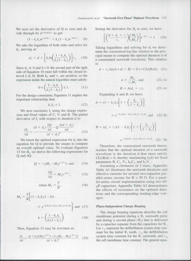
We next set the derivative of Q to zero and di-vide through by e"'* ' i'' ''i to get:
(1 - kX)e~^'''-'' = K( 1 - kje-^'^^'. (9)
We take the logarithm of both sides and solve ford|. arriving at:
= d + \ kjn r,. (10)
Since d, > 0 and d > 0, the second part of the rightside of Equation 10 must fall within the closed in-terval [-d, 0]. Both k . and r, are positive, so theexpression inside the natural logarithm must satisfy:
For the design constraints, Equation 11 implies theimportant relationship that:
k,k,<\, (12)
We next maximize I using the charge expres-sion and fixed values of C, V, and R. The partialderivative of I . with resF)ect to duration d is:
+ d,)
dddd (d +
(13)
We insert the optimal expression for d, into theequation for Q to provide the means to computean overall optimal value. To evaluate Equation13 for d\^, we derive the following expressions forQ and^Q:
Q ^ '), and
dd
Vwhere A/, = —,
(14)
(15)
(16)
Then, Equation 13 may be rewritten as:
'dd (d + d,f(19)
Setting the derivative for d\ to zero, we have:
V + d,. + T
M,(20)
Taking logarithms and solving for d, we deter-mine the constrained log-line relation as the prin-cipal means to compute the optimal duration d ofa constrained sawtooth wavefonn. This relationis:
d-
A = -, and
B = A(d^ + r^).
Expanding A and B, we have:
k..
, (21)
(22-A)
(23-A)
1 -
(22-B)
B =k..
1 - k..
- f t . (23 — B)
Therefore, the constrained sawtooth theoryteaches that the optimal duration of a sawtoothwaveform is the duration d that must satisfyCLLR(d) = 0, thereby maximizing I (d) for fixedparameters R, C,, V,, k^C,, and k^V, .
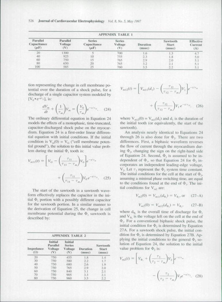
Assuming a chronaxie of 3 msec. AppendixTable Al illustrates the sawtooth durations andeffective currents for several two-capacitor par-allel-series circuits for R = 50 Q. For a paral-lel-series circuit implementation using two 60-fiP capacitors. Appendix Table A2 demonstratesthe effects of resistance on the optimal dura-tions and the corresponding leading-edge volt-ages.
Phase-Independent Charge Burping
The charge burping equations describe the cellmembrane potential during a 4>, sawtooth pulseand during a second phase (<I> ) that is deliveredby a capacitor separate from the capacitors for *l>|.Let r,, represent the defibrillation system time con-stant for the initial ^i tooth, r,^ the defibrillationsystem time constant for the 4>| sawtooth, and r^the cell membrane time constant. The general equa-
526 Journal of Cardiovascular Electrophysiology Vol. 8. No. 5. Mav 1997
APPKNDIX TABLE I
ParallelCapacituncc
ParalklVoltage
(V)
SeriesCapacitance
SeriesVoltage
(V)Dunition(msec)
SawtoothStart
(msec)
EffectiveCu rreiit
( A t
20406080100
1300925750650585
510152025
7(M»755765765760
1.62.32.93.23.5
1.31.82.02.12.2
4.75.05.15.15.1
tion representing the change in cell membrane po-tential over the duration of a shock pulse, for adischiirge of a single capacitor system modeled by[Vfl-e-^ii], is:
dtV... = I ^ (24)
The ordinary differential equation in Equation 24models the effects of a monophasic, tinie-truncated,capacitor-discharged shock pulse on the myocar-dium. Equation 24 is a first-order linear differen-tial equation with initial conditions. If the initialcondition is VJO) = V^ ("cell membrane poten-tial ground"), the solution to this initial value prob-lem during the initial ^ | tooth is:
(25)
The start of the sawtooth in a sawtooth wave-form effectively replaces the capacitor in the ini-tial 4>| portion with a possibly different capacitorfor the sawtooth portion. In a similar manner tothe derivation of Equation 25. the change in cellmembrane potential during the $, sawtooth isdescribed by:
APPKNDIX TABI.K 2
Initial IntlialPiirallel Series Sawtooth
Impedance Voltage Voltage Duration Start(U) (V) (V) (msec) (msec)
20304050607080
7507.'iO750750750750750
435580680765840905960
I.S2.22.62.93.13.33.5
1,41.71.92.02.12.12.2
V,
(26)
where V,,,,-,{0) ~ V^,||(d|) and d, is the duration ofthe initial tooth (or equivalently, the start ol thesawtooth).
An analysis nearly identical to Equations 24through 26 is also done for 4»2. There are twodifferences. First, a biphasic waveform reversesthe flow of current through the myocardium dur-ing ^^, changing the sign on the right-hand sideof Equation 24. Second, ^^ ' ^ assumed to be in-dependent of <I'|. so that Equation 24 for < ; in-corporates an independent leading-edge voltage.Vj. Let T-. represent the ^ , system time ct>nslant.The initial conditions for the cell at the stiut of <!>,.assuming a minimal phase switching time, iire equalto the conditions found at the end of 4>|. The ini-tial conditions for V, ^ are:
V«2(0) = V,,,n(^.,,,)= V,.,.or (27-A)
V, 2(0) - V,,,nid^) = V,,,. (27-B)
where d.,, is the overall time of discharge for $,and V . is the voltage left on the cell at the end of^,. For a conventional hiphasic shock pulse, theinitial condition for 4>; is determined by Equation27A. For a sawtooth shock pulse, the initial con-dition for f . is determined by Equation 27B. Ap-plying the initial conditions to the general <I>n so-lution of Equation 24, the solution to the initialvalue problem for ^ is:
T-, - T.
.-//r. (28)
Yamanouchi. et al. "Sawtooth First Phase" Biphasic Waveform 527
Equation 28 provides a means to calculate theresidual membrane potential at the end of ^2- Weset Equation 28 equal to zero and solve for t. Thesolution for t is the optimal charge burping dura-tion for $2, denoted by d .,. Arranging the expo-nential functions to one side and taking the loga-rithm of both sides, we solve for d,p, to get:
d,. =- r.
In I + . (29)
Design of the Second Phase
The 4>|-based sawtooth waveform was evalu-ated for its ability to charge burp myocardialcells during <I> . The evaluation showed that therewas not enough current remaining in the capaci-tors following ^1 to properly charge burp cells; ^^ended before it had removed a sufficient amountof the residual charge.
Therefore, a ^>, waveform independent of $ ,was designed, and a separate <3>2 capacitor wasadded to the delivery circuit. The separate capac-itor provided sufficient current to charge burp thosecells unaftected by 4>i. The design criteria of ^2constrained it to be < 10 msec in duration,, to havea final voltage > 25 V, and to reduce the residualcharge by > 85%. Relative cell membrane poten-tial equal to 35% of the external voltage gradientwas assumed.
For a fixed energy value, the smallest capacitancethat pnxiuced the shortest duration was chosen asthe capacitance for ^-, charge burping. The ^2 ^^~sign that best met these constraints comprised a 2-J. single 30-//F capacitor, charged to 365 V and dis-chaig:ed for 3.5 msec. This 4>2 was added to the $,sawtooth waveform to create a biphasic wavefonn.
Ackiwwkdgmeni: We would like to thank Donald G. Hills tor histechnical assistance.
References
1, Geddes LA. Niebiiuer MJ. Babbs CF. et al: Fundamen-tal criteria underlying the efficacy and safety of defib-rillating current waveforms. Med Biol Eng Comp1985;23:I22-I3O.
2. Bourland JD, Tacker WA. Geddes LA. et al: Compara-tive efficacy of damped sine wave and square wavecurrent for transchesl ventricular defibrillation in ani-mals. Med Instrument 1978;12:42-45.
3. Kavanagh KM, Tang ASL, Rollins DL. el al: Compari-son of the internal defibrillation thresholds formonophasic and double and single capacitor biphasicwaveforms. J Am Coll Cardiol 1989; 14:1343-1349.
4. Dixon EG. Tang ASL. Wolf PD. et al: Improved defi-brillation thresholds with large contotired epicardialelectrodes and biphasic waveforms. CirculationI987;76:l 176-1184.
5. Chapman PD. Vctter JW. Souza JJ. et al: Comparativeefficacy of monophasic and biphasic truncated expo-nential shocks for nonthoracotomy internal defibrilla-tion in dogs. J Am Coll Cardiol l988;l2:739-745,
6. Winkle RA. Mead RH. Ruder MA. ct al: Improved lowenergy defibrillation efficacy in man with the u.se of abiphasic truncated exponential wavefonn. Am Heart J1989;! 17:122-127.
7. Saksena S. An H, Krol RB, et al: Simultaneous bipha-sic shocks enhance efficacy of endocardial cardiover-sion defibrillation in man, PACE 1991 ;14:1935-1942.
8. Bardy GH, Troutman C. Johnson G, et al: Electrodesystem influence on biphasic waveform defibrillationefficacy in humans. Circulation I991;84:6f).'i-671,
9. Blanchard SM. Ideker RE: Mechanisms of electricaldefibriliation: Impact of new experimental defibrillatorwaveforms. Am Hean J 1994:127:970-977.
10. Walcott GP. Walcott KT. Knislcy SB. ct al: Mecha-nisms of defibrillation for monophasic and biphasicwaveforms. PACE 1994; 17:478-498.
11. Kroll MW: A minimal model of the single capacitorbiphasic defibrillation waveform. PACE I994;17:1782-1792.
12. Brevi-er JE, Tvedt MA. Adams TP. et al: Low voltageshocks have a significantly higher tilt of the internalelectric field than do high voltage shocks. PACE1995:18:214-220,
13. Kroil MW: A minimal model of the tnonophasic defi-brillation pulse. PACE 1993:16:769-777.
14. Gold JH. Schuder JC. Stoeckle H. et ai: Transthoracicventricular defibrillation in the 100 kg calf with unidirec-tional rectangular ptilses. Circulation 1977:56:745-750.
15. Rist K. Tchou P, Mowrey K. et at: Smaller capacitorsimprove the biphasic waveform. J Cardiovasc Eleciro-physiol 1994:5:771-776.
16. Yamanouchi Y. Mowrey K. Nad/am G. et al: Thelarge change in voltage at phase reversal improvesbiphasic defibrillation thresholds: Parallel-series modeswitching. Circulation 1996;94:1768-1773.
17. Kirk RE: Experimental Design: Procedure.^ for the Be-havioral Sciences. Brooks/Cole Publishing Company.Belmont,CA. 1982. pp. 106-110.
18. Geddes LA. Tacker WA. McFartane J. ei al: Strength-duration curves for ventricular defibrillation in dogs,CircRes 1970:27:551-560.
19. Niebauer MJ. Babbs CF. Geddes LA. et a!: Efficacyand safety of defibrillation with rectangular waves of 2to 20-milliseconds duration. Crit Care Med 1983:11:95-98,
20. Feeser SA. Tang ASL, Kavanagh KM, et al: Strength-duration and probability of success curves for defihril-

528 Journal of Cardiovascular Electrophysiology Vol. 8. No. 5. May 1997
lation with biphasic waveforms. Circulation 1990:82:2128-2141.
21. Schtider JC. McDaniel WC. Sloeckle H: Defibriltationof 100 kg calves with asymmetrical, bidirectional, rec-tangular pulses, Cardiovasc Res 1984; 18:419-426.
22. Jones JL. Jones RE: Improved defibrillator wavefonnsafety factor with biphasic waveforms. Am J Physiol1983:245:H60-H65,
23. Jones JL. Jones RE: Decreased defibrillator-induceddysfunction with biphasic rectangular waveforms. AmJ Physiol I984:247:H792-H796.
24. Walcott GP, Rollins DL, Smith WM. et al: Effect ofchanging capacitors between phases of a biphasic defi-brillation shock, PACE 1996:19:945-954.
25. Tang ASL. Yabe S. Wharton JM, et al: Ventricular de-fibrillation using biphasic waveforms: The importanceof phasic duration. J Am Coll Cardiol 1989:13:207-214.
26. Swerdlow CD, Fan W. Brewer JE: Charge burping pre-dicts optimal ratios of phase durations for biphasic de-fibriilation. Circulation l996;94:2278-2284.
27. Walcott GP, Walker BA. Cates AW. et al: Choo.singthe optimal monophasic and biphasic waveforms forventricular defibrillation- J Cardiovasc ElectrophysiolI995;(i:737-75O.
28. Bourland JD. Tacker WA Jr, Wessale JL. et al: Se-quential pulse defibrillation for impiantable defibrilla-lors, Med Instrument 19S6;20:138-142.
29. Rubio PA. Farrell EM: Low-energy direct defibrillationof the human heart. Ann Thorac Surg 1979:27:32-33,
30. Fontaine G. Cansell A. Lechai P, et at: Unipolar elec-trode system for an impiantable defibrillator: New ex-perimental approaches. PACE I984;7:I351-1356.
31. Eysmann SB. Marchlinski FE. Buxton AE. et al: Elec-trocardiographic changes after cardioversion of ven-tricular arrhythmias. Circulation I986;73:73-81.
32. Li HG. Jones DL. Yee R. el al: Detibrillation shocksproduce different effects on Purkinje fibers and ven-tricular muscle: Implications for successful defibrilla-tion. refibrillaiion and postshock arrhythmia, J AmColl Cardiol I993;22:6O7-6I4.