MASTER THESIS - Halmstad University
83
MASTER THESIS Master's Programme in Mechanical Engineering, 60 credits Design and Construction of Chassis for Uniti L7e vehicle Anoop Bharadwaj Yellambalse Prem Kumar, Pavan Kumar Maareddygari Master Thesis 15 credits Halmstad 2016-12-30
-
Upload
khangminh22 -
Category
Documents
-
view
2 -
download
0
Transcript of MASTER THESIS - Halmstad University

MA
ST
ER
THESIS
Master's Programme in Mechanical Engineering, 60 credits
Design and Construction of Chassis for Uniti L7evehicle
Anoop Bharadwaj Yellambalse Prem Kumar, Pavan KumarMaareddygari
Master Thesis 15 credits
Halmstad 2016-12-30

i
PREFACE
The following Thesis report is an important scholarly achievement that should be presented
with pride, which has been prepared by ANOOP BHARADWAJ and PAVAN KUMAR
MAAREDDYGARI as part of the completion of the master’s education in Mechanical
Engineering, Halmstad University. This report is a product of all the knowledge gained during
our study in this honorable institute and our past bachelors education.
Several persons have contributed academically, practically and with support to this master
thesis. We would therefore firstly like to thank our University Supervisor Dr. Lars Bååth and
Industrial supervisor, Mr. Michel Bano, Head of Research and Development at Uniti Sweden
AB, for their time, valuable input and support throughout the execution of master thesis.
Furthermore, we would like to thank Mr. Lewis Horne CEO Uniti Sweden AB and Dr. Bengt-
Göran Rosén Examiner for their big help throughout the entire process of find the Master’s
thesis.
Finally, we would like to thank our family and friends for being helpful and supportive during
our time studying Master’s in Mechanical Engineering at Halmstad University.

ii
ABSTRACT
Chassis is the primary structural component of an automobile. It is the main supporting
structure of a vehicle to which all other systems like braking, suspension and differential are
attached. In this thesis, a methodology for L7e category vehicle chassis design and structural
stability analysis is presented. The present car being developed at Uniti Sweden AB is classified
as L7e category vehicle as per the European Union, therefore the chassis developed in this
thesis considers the specific characteristics that vehicles under this category demands for.
A literature study is carried out to review various existing designs of vehicle chassis, latest
innovations and advanced materials used to manufacture the same. The various types of forces
and stresses commonly acting on chassis structures are analyzed and their effects on the
vehicle is understood. After completing literature study, several findings are listed in a
systematic manner, by providing ample arguments to justify each of them. The pro-con analysis
is conducted to evaluate merits and demerits of each alternative type of chassis and the material
to manufacture it. The most essential design criteria are derived from the QFD (Quality
function deployment) which then acts as important guidelines during the actual design process.
Structural chassis frame is designed as per the design criteria, using the CAD software
CATIAV5R19 and the structural stability of the same is tested and analyzed using ANSYS 15.0
software. From the results of these analysis tests the static structural stability of the design is
confirmed.
Keywords: L7e category European Vehicle, Uniti Sweden AB, Pro-con analysis, QFD (Quality
function deployment), CAD software CATIAV5R19, ANSYS 15.0 software, static structural
stability.

iii
CONTENT
CHAPTER 1: INTODUCTION……….……………………………...…..1
1.1 Background………………………………………………………………………..….1
1.2 Aim of the Study……………………………………………………………….……..2
1.2.1 Problem Definition ……………………………………....…………...…….......…..2
1.3 Limitations……………………………………………………………………......…..2
1.4 Individual Responsibility and efforts during the Project………………………..……2
1.5 Overview of the Company…………………………………………………………....3
CHAPTER 2: METHODOLOGY…………..………………...…………..4 2.1 Alternative Methods…………………………………………………………….…….4
2.2 Chosen methodology for this project…………………………………………………5
2.3 CES EduPack…………………………………………………………………………6
2.4 Preparation and Data collection………………………………………...…………….7
CHAPTER 3: THEORY………………….....……………….……………8
3.1 Chassis Types…………………………………………………………………...…….8
3.2 Types of Stresses acting on the Chassis……………………………….......………...13
3.3 Material Selection…………………………………………………………………...15
3.3.1 Materials used for chassis manufacturing……………………………………..15
3.3.2 Advanced materials…………………………………………….......………….16
CHAPTER 4: RESULTS……………………………….……………..…18 4.1 House of Quality for Types of chassis…………………………………………...….18
4.1.2 Pro- Con Analysis for the types of chassis…………………………………….21
4.2 House of Quality for Material Selection……………………………………….………..23
4.2.1 Pro Con Analysis for material selection………………………………….……26 4.3 Design of Chassis……………………………………………………………………29 4.4 Analysis of Chassis………………………………………………...………………..32 4.5 Static Structural Analysis………………………………………………………..…..34
CHAPTER 5: CONCLUSION…………………………………………..35 CHAPTER 6: CRITICAL REVIEW………………………………..…..36 CHAPTER 7: REFERENCES…………………………………….……..38 CHAPTER 8: APPENDEX………………………………………………40 List of figures……………………………………………………………………………78 List of Tables…………………………………………………………………..………..78
1
CHAPTER 1: INTODUCTION 1.1 Background
The word chassis was derived from the Middle French Chaciz, from chasse in the year 1864.
A chassis is a physical frame or structure of an automobile, an airplane, a desktop computer, or
any other multi-component device. In simple words, something leftover when body is removed
from a vehicle is called “chassis”. It is the main supporting structure of a vehicle to which all
other components are attached, and it can be comparable to the skeleton of a living organism.
The components of the vehicle like transmission system, axles, wheels, tyres, suspension,
controlling system like braking, steering, etc., and even electrical systems are mounted on the
chassis frame. Chassis is the main mounting for all the components including the body. So, it
is also called as the ‘Carrying unit’ and the Backbone of a vehicle.
Until 1930’s, virtually every vehicle had a structural frame, separate from the cars body. This
construction design is known as “body- on- frame”. Since then, nearly all passenger cars have
received Uni-body construction, meaning their chassis and bodywork has been integrated into
one another. The last United Kingdom mass-produced car with separate chassis was Triumph
Herald, which was discontinued in 1971. However, nearly all trucks, busses, and pickups,
continue to use a separate frame as their chassis.
The objective of this project is to design and construct a chassis for an L7e CP vehicle called
Uniti. This new conceptual car aims to revolutionize the way cars are made, as cars of today
are outdated as they have been made in the same way from decades. To design a chassis for
Uniti car, we have carried out a detailed study about the various theories of chassis. We have
listed the various types of load conditions, types of stresses acting on a vehicle frame, the
different type of requirements a chassis design must meet. In addition, we also studied about
the different types of chassis existing in the car industry.
As the car being developed is an electric car of L7e CP category, as per the European Union
regulation on approval of L-Category Vehicles it follows some of the constraints as listed
below:
It is a Heavy quadric-mobile (four wheels) vehicle.
Its maximum power should not exceed more than 15 KW.
It has a maximum design speed restricted to 90 km/h.
And with an enclosed passenger compartment that can accommodate maximum of four
non-straddle seats.
The chassis is designed by the CAD/CAM software CATIA V5R19 which is a 3D CAD, CAM,
and CAE platform for product development. It combines the industrial and mechanical design,
simulation, collaboration, and machining in a single package. The tools in this software enable
fast and easy exploration of ideas with an integrated concept-to production toolset.

2
1.2 Aim of the Study
The main aim of the project is to design a chassis for Uniti L7e vehicle, which is a new type of
an electric car being developed by the company Uniti, by considering all the different aspects
of environmental sustainability. We also aim to analysis the stresses acting on our design with
stress analysis software.
a) Selecting the best chassis type from the existing types of chassis so that it
suits the design requirement of the Uniti car.
b) Selecting the best material for the chassis of Uniti car, that can answer light
weight features.
c) Designing the chassis as per the design requirements of the L7e CP category
vehicle using the CAD (Computer Aided Design) software CATIA V5 R19
d) Analysing the developed chassis design using the simulation software
ANSYS 15.0 to check for structural stability.
1.2.1 Problem Definition
An ideal chassis is to be designed and developed for the prescribed vehicle such that the design
meets all the stated design criteria thus proving to be structurally stable. The CAD model and
the analysis reports of the same are the deliverables of the project. 1.3 Limitations
The present thesis is intended to provide a suitable design for a chassis for the lightweight
vehicle described above. While it includes a finite element analysis that confirms the suitability
of said design and material selection, the final manufactured product may need to be further
adjusted to satisfy some real-world requirements that are difficult to model or assess ahead of
physical testing.
The design and construction of chassis for a vehicle is a very complex process which usually
involves many iterations and great scrutiny to achieve ideal results. Considering this a thesis
project, adhering to the design standards found in the industry is unrealistic, especially
regarding deadlines. Therefore, the main contribution of this thesis is the capturing of design
requirements and customer preferences through QFD and their translation into numerical target
specifications and the formulation of a chassis design that fulfils these targets. The simulation
step is provided as confirmation that said targets have been met.
1.4 Individual Responsibility and efforts during the Project
All the different aspects listed in the problem definition of this project were undertaken after
thorough discussion and understanding of all the concepts behind each part of the project. Both
team members have shared responsibility equally in all required tasks. The various topics
discussed in the following thesis are based on the literature review, which consisted in the
analysis of various technical articles and textbooks, and is supplemented by the knowledge
gained previously from past courses.

3
1.5 Overview of the Company
Uniti Sweden AB is a start-up company established in the early 2016, and whose goal is to
create an innovative and futuristic electric car that is environmentally sustainable provides a
great driver experience. Uniti is currently in the developmental stage in Pro-lab at Lund
University. The Company aims to launch its first model by the year 2018.
4
CHAPTER 2: METHODOLOGY
2.l Alternative Methods
The project is about the design and construction of the chassis for the Uniti L7e vehicle, which
requires basic knowledge about the various types of existing chassis or frame designs and the
materials used for their manufacture, as well as the current trends of the automotive Industry.
As this is a product development project, we have made use of all the different stages of product
development referred to in David G. Ullman’s ‘The Mechanical Design Process’. The following
set of design phases are the sources of alternative methods to interact with a problem solution.
Product Discovery:
The project has been initiated to find the best suitable design for the construction of the chassis
of the Uniti L7e Vehicle. In this stage, we also investigate the best suitable material for the
manufacture of the chassis as well as identify the most suitable chassis frame.
Project Planning:
The planning is done to make the product, so that all the various stage of product development
is implemented correctly so that the best solution of product development could be achieved to
finally build a proto type of the chassis design.
Product definition:
All the dimensional specifications of the final design should be finalized with consultations
with both Industrial and University supervisors such that the design meets the design criteria.
QFD is a strategical technique used to identify customers for the product, generating customer
requirements and converting to a technical specification, evaluating the completion and
prioritize the system specifications as for customers of the product.
Conceptual Design:
This design is generated by using the results of QFD, Pro-Con and brainstorming. The chassis
is to be developed, designed, and analyzed such that it can be perfectly suitable for the comfort
of Uniti car users.
Product Development:
This stage involves the development of the QFD in which different concepts are compared until
the best suitable design is implemented. This is the best concept for each function is further
selected and evaluated from an entirely new product. But this approach is not selected for this
project, as no new product is being developed, instead, an existing system is modified.
Product Support:
The Final design of the chassis shall be the property of the company Uniti Sweden AB and all
aspects of product support will also be dependent on the company.
5
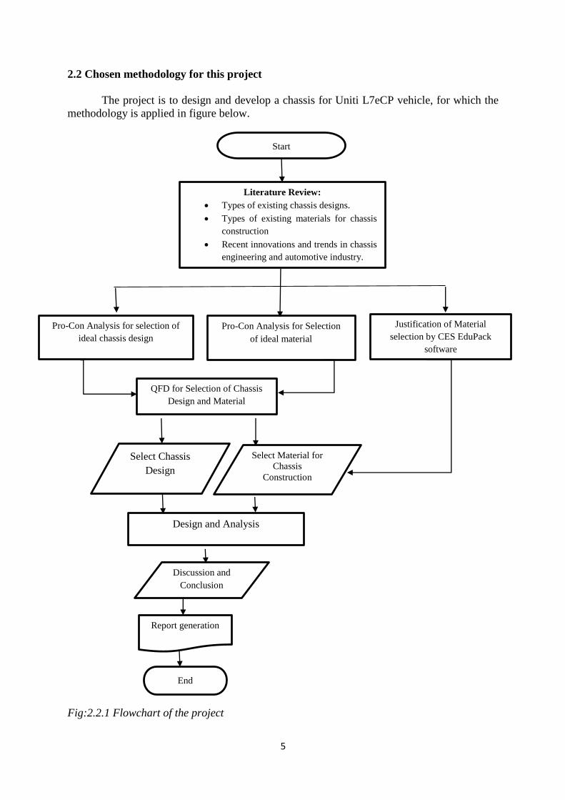
2.2 Chosen methodology for this project
The project is to design and develop a chassis for Uniti L7eCP vehicle, for which the
methodology is applied in figure below.
Fig:2.2.1 Flowchart of the project
Start
Literature Review:
Types of existing chassis designs.
Types of existing materials for chassis
construction
Recent innovations and trends in chassis
engineering and automotive industry.
Pro-Con Analysis for selection of
ideal chassis design
Pro-Con Analysis for Selection
of ideal material
Justification of Material
selection by CES EduPack
software
QFD for Selection of Chassis
Design and Material
Select Chassis
Design
Select Material for
Chassis
Construction
Design and Analysis
Discussion and
Conclusion
Report generation
End

6
(a) Literature review
All basic information required to go ahead with the project is collected and reported in
Chapter 3, which include theory of automobile chassis types, different designs, different
materials, and advanced materials for manufacturing.
(b) Pro-Con Analysis
Pro-con Analysis is a common problem solving technique which frequently requires
decision making which is important to improve quality of decisions. Problem-solving and
decision-making are closely linked, and each requires creativity in identifying and developing
options, for which the brainstorming technique is particularly useful. Good decision-making
requires a mixture of skills: creative development and identification of options, clarity of
judgement, firmness of decision, and effective implementation.
(c) QFD (Quality function Deployment)
The Quality Function Deployment process begins with identifying who the customers
are (step 1) and what they want the product to do (step 2). In developing this information, we
also determine to whom the what is important - an analysis of who versus what (step 3). Then,
it is important to identify how the problem is solved, in other words, what the competition is
for the product being designed (step 4). This information is then compared to what the customer
desires- now versus what (step 4 continued) - to find out where there are opportunities for an
improved product.
Next comes one of the most difficult steps in developing the house of quality in determining
how (step 5) you are going to measure the product’s ability to satisfy What vs how (Step 6)
given in the customer’s requirements. Target information- how much (step 7)- is developed in
the basement of the house. Finally, the interrelationship between the engineering specifications
are noted in the attic of the house- How versus how (Step 8)
In the product development step, the QFD provides the various solutions with engineering
specifications for various problems that researchers have. It gives a complete structure for the
development and allows us to know the more specific requirements. The solutions developed
from the QFD is made used for concept generation. [1]
2.3. CES EduPack
This is a unique set of teaching resources that support materials education across
engineering, Design, Science, and sustainable development. CES EduPack is the world’s
leading teaching resource for materials. It has been exclusively developed by granta design in
collaboration with professor Ashby and growing community of educators of 1000 universities
and colleges around the world. Material selection is a step in the process of designing any
physical object. In the context of product design, the main goal of material selection is to
minimize cost while meeting product performance goals. Systematic selection of the best
material for a given application begins with properties of the candidate materials. The enhanced
eco audit tool is used for higher level of teaching and research which comes with the CES
EduPack eco design edition, adds consideration of the following process options. It is also
possible to calculate cost for the different life cycle phases, helping students to think about both
environmental and economic factors. The Eco design editor comes with extended property data

7
for over 3750 materials. This allows CES EduPack’s powerful selection and analysis software
to be used in projects to investigate and compare the environmental impact of materials and
processes. The enhanced eco audit tool can be used as part of a 2-step process in which the
student first analyses a product to identify the key drivers of its environmental impact and then
move on to make materials selections that impact. [2] So, we are selecting a material by using
CES EduPack software, which can be observed from the graphs present in the Appendix.
2.4. Preparation and Data collection:
We have taken guidance for completion of the thesis from our Industrial Supervisor Mr. Michel
Bano and our University Supervisor Mr. Lars Bååth. This project required the complete
understanding of the various concepts of the automobile design. Our Industrial supervisor
provided the design requirements and criteria upon which the final CAD design was generated
using the CAD software CATIA V5R19. Later the generated design was analyzed for structural
stability using the ANSYS 15.0 software. Followed by construction of the proto type by using
the 3D printing technology.

8
CHAPTER 3: THEORY
3.1 Chassis Types
1. Ladder Frames
The ladder frame is one of the simplest and oldest of all designs. It consists of two symmetrical
beams, rails, or channels running the length of the vehicle. The ladder frame is called so because
it resembles a ladder with two side rails and several cross beams. The ladder frame chassis is
constructed with cross beams of channel sections as well as side frames; this because of the
torsional stiffness to the whole structure is very low. [4]
Figure: 3.1.1 Ladder Frame [11]
The torsion in the cross members is reacted as bending in the side frames, and the bending in
the cross members, reacted as torsion in the side frames. It is also observed that all the members
are loaded in torsion and due to their low torsional constants. This frame has low torsional
stiffness. The important point is to notice that if the open sections are replaced by closed
sections, then the torsional stiffness is greatly increased. This can be observed in the vehicles
such as Land Rover. The greatest advantage of the ladder frame is its adaptability to
accommodate various vehicle body shapes. It is particularly used for light commercial vehicles.
It is still widely used for box vans and tankers to detachable containers. [3]
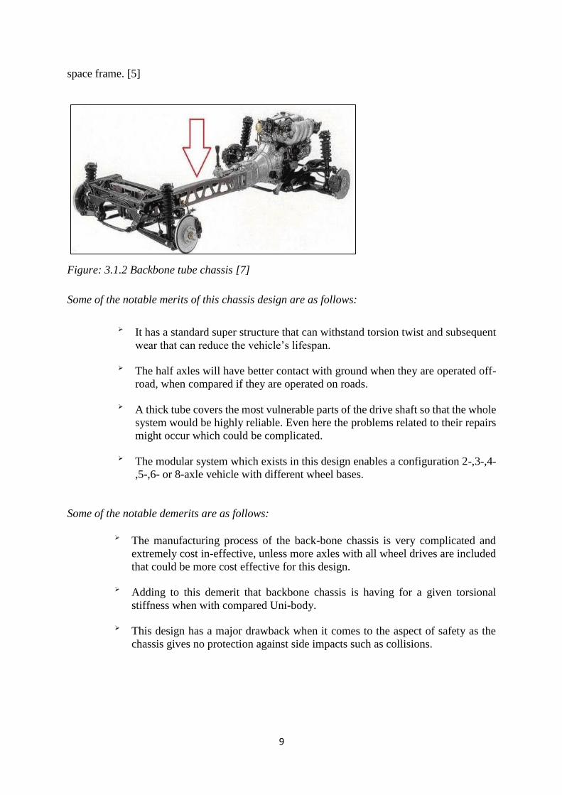
2. Backbone tube Chassis:
The back-bone tube design is very commonly found in sports cars. It consists of a strong tubular
back bone which is usually rectangular in cross section that connects the front and rear
suspension attachments of the vehicle. This design was first developed in 1923 by Hans
Ledwinka who was the chief designed at Tatra heavy trucks.
He further enhanced this design with 6*4 model Tatra 26, which had great off road abilities.
Some of the vehicles which are using this chassis design are Europa, Lotus E spirit and Skoda,
etc. Some cars also make use of the backbone part of the chassis to strengthen is such as
Volkswagen Beetle. Thus, the concept of hybrid backbone ladder chassis developed. On this
regard the Locost was developed by using this concept of a backbone in addition to the outer
9
space frame. [5]
Figure: 3.1.2 Backbone tube chassis [7]
Some of the notable merits of this chassis design are as follows:
It has a standard super structure that can withstand torsion twist and subsequent
wear that can reduce the vehicle’s lifespan.
The half axles will have better contact with ground when they are operated off-
road, when compared if they are operated on roads.
A thick tube covers the most vulnerable parts of the drive shaft so that the whole
system would be highly reliable. Even here the problems related to their repairs
might occur which could be complicated.
The modular system which exists in this design enables a configuration 2-,3-,4-
,5-,6- or 8-axle vehicle with different wheel bases.
Some of the notable demerits are as follows:
The manufacturing process of the back-bone chassis is very complicated and
extremely cost in-effective, unless more axles with all wheel drives are included
that could be more cost effective for this design.
Adding to this demerit that backbone chassis is having for a given torsional
stiffness when with compared Uni-body.
This design has a major drawback when it comes to the aspect of safety as the
chassis gives no protection against side impacts such as collisions.

10
3. X- Frame or Cruciform Frame:
General Motors used the X-Frame design, during the late 1950’s and early 1960’s. In which the
rails from alongside the engine seamed to cross the passenger compartment, each containing to
the opposite end of the cross beam at the extreme rear of a vehicle.
Figure: 3.1.3 X- Frame or Cruciform Frame [3]
This design was particularly chosen to decrease the overall weight of the vehicle regardless of
the increment in the size of the transmission and propeller shafts humps, since can row had
taken cover the frame rails. It is also observed that several models have differential located not
by the customary bar between axle and frame but by a ball joint atop the differential connected
to a socket in a wishbone hinged on to a cross-member of the frame. The major drawback of
this design is that it lacks side rails thus it fails to provide adequate side impact and collision
protection. Thus, this design also fails on the aspect of design safety. Thus, the perimeter frame
has replaced this X-frame. [3]
4. Perimeter Frame:
The perimeter frame tries to overcome the drawbacks of the x-frame design. It is mainly used
in motorcycles, having different shapes and sizes. The reason for this is most motorcycles have
a warped version of this tubular frame design. The main aim of this design is to create the
shortest path between the most stressed parts of the motorcycle, for maximum stiffness and
stability. In his design the front forks are mounted at the left most end and the rear swing arm
is attached to the right most. The engine is placed in the empty space between them. The
perimeter frame can be seen to be used in Bajaj Pulsar 200 Ns motorbike. The engine is
suspended in the middle with the wire frame around it. The cylinder head also exerts stress on
the frame thus increasing and maximizing the stiffness of the frame, as the weight of the
perimeter frame is low. It helps in mass centralization hence improving the handling
characteristics of a vehicle. [15]

11
Figure: 3.1.4 Perimeter Frame [6]
5. Space Frame:
It is also known as 3-Dimentional chassis frame. It is called so because unlike other chassis
types which are essentially 2-dimensional having only length and breadth in this design the 3rd
dimension has been considered. By considering the depth of the frame 3-D Frames have
managed to increase the bending strength and stiffness of the entire design. [3]
Figure: 3.1.5 Space Frame [9]
These types of frames have been mainly used for specialist cars such as sports racing cars. Some
of the notable examples for space frame cars include Audi R8, Ferrari 360, Lamborghini
Gallardo, Mercedes-Benz SLS AMD and Pontaic Fiero.
This type of vehicle design can be mainly used for low volume production. One important
aspect of this vehicle structure is that all the planes of the frame should be fully triangulated, so
that all elements are essentially loaded in tension or compression. The main drawback of this
design is that it encloses much of the working volume of the car and it can make access for both
the driver and the engine difficulty, therefore the Space frames have been designed with
removable section joined by pin-joints. Such a structure can be seen around the engine of the
Lotus Mark III. Although the space frame design is considered somewhat inconvenient for its

12
passengers, the, main advantage of this design is the lack of bending forces in the tubes that
allow it to be modelled as a pin jointed structure meaning that the removable sections need not
be designed to reduce the strength of the assembled frame. [3]
6. Uni-body Frame:
It is also known as the monocoque structure. In this design the vehicle frame and body are
integrated into one single strong structure. This integral frame and body construction requires
more than just welding an unstressed body as see in conventional frames. It is a fully integrated
body structure where the entire car is a load caring unit that handles all the loads experienced
by the vehicle i.e. the forces acting on the vehicle during motion, as well as the cargo loads.
These types of integral bodies for wheeled vehicles are manufactured by forming or casting
whole sections as one piece or by welding metal panels and other components together by
forming or by a combination of all these techniques. This is because the car outer skin and
panels are made as load bearing having ribs, bull heads and box sections to reinforce the entire
body. From the 1990’s onwards the safety regulations for chassis designs became stricter thus
more rigid chassis were developed. The traditional steel monocoque which was being used at
that time became increasingly heavy. This made vehicle designers to turn towards alternative
materials to replace steel, which lead to the introduction of aluminum as an alternative. There
has been no mass production of any other car other than Audi A8 and A2 which could complete
eliminate steel in the chassis construction. From this time, onwards increasingly cars started
using aluminum in their body panels such has bonnet, boot lid, suspension arms and mounting
sub-frames. [3]
Figure: 3.1.6 Uni-body Frame [10]
The manufacturing technique, conventionally used for Uni-body construction was pressing. But
this technique had a major drawback, pressing used heavy-weight machines to press sheet
metals in to die, this created in homogeneous thickness, which made the edges and corners
always thinner than surfaces. To maintain a minimum thickness, the car designers had to choose
thicker sheet metals than the originally needed. These situations lead to the Hydro-form
technique to be introduced.
In this technique, instead of using sheet metal, it forms thin steel tubes. And these steel tubes
are placed in a die that can define the desired shape when a fluid of high pressure is pumped in

13
the tubes expanding the latter to the inner surfaces of the die. As the pressure of the fluid
involved is non-uniform, the thickness of the steel made is also non-uniform. Thus, the
designers using this technique manage to minimize the steel thickness and reduce the weight of
the structure. [3]
7. Sub Frame:
The main advantage of this chassis is that it is stronger and lighter than the conventional
monocoque design without increase of production cost. And the main drawback of this chassis
is that it is still not strong or light enough for the sports cars. [13]
Figure: 3.1.7 Sub-Frame [8]
These sub frames are commonly found at the front or rear end of vehicles and are used to
attach the suspension to the vehicles. It may also contain the engine and transmission and it’s
normally a tubular or box sheet construction. Some of the examples of passenger cars using
such a construction are the 1967- 81 GMF Platform and the GMX Platform 1962. [13]
3.2 Types of Stresses acting on the Chassis:
After studying about the various loads acting on the vehicle the following types of stresses can be identified, such as
1. Allowable Stress:
It is important to understand the worst load conditions that the stresses induced into the structure of the vehicle to keep these stresses within acceptable limits.
By considering all the static load factors acting on a road going passenger car the stress level should be below the yield stress.
Example, In the case of a road going passenger car its bending case is having the maximum allowable stress which should be limited as follows.
Stress due to static load * Dynamic Factor ≤ 2/3 *Yield Stress

14
From the above equation, we can understand that the worst dynamic load condition acting on
the vehicle structure should not exceed more than 67% of the yield stress. In addition, the safely
factor against yield is 1.5 for the worst possible load conditions on the vehicle structure.
Therefore, the above procedure is usually suitable for designing against fatigue failures, but the
fatigue investigation at the points where the stress concentration occurs such as the suspension
mounting points. [3]
2. Bending Stiffness:
From the previous sections of loads and stresses which we have considered thus we can now
determine whether a passenger car structure is sufficiently strong most designers are
considering stiffness is more important that strength. Therefore, designing for acceptable
stiffness is more critical than designing for sufficient strength.
The bending stiffness in the case of passenger cars can be determined by the acceptable limits
of deflection of the side door. In the case of excessive deflection, the door of the passenger cars
will not shut satisfactorily due to the misalignment of the door latches resulting in a situation
where the doors cannot be opened or shut easily.
Any deflection of the floor under the passenger’s feet is a case of concern as it results in
passenger insecurity. Therefore, the load stiffness of the floor is important for passenger
acceptance. To reduce the panel vibrations of the floor, these floor panels are stiffened by
swages pressed into the panels to reduce the deflections, and panel vibrations. Currently modern
passenger cars use sandwich material having 2 thin panels separated by a honey comb material
which leads to a much lesser deflection and vibration of the vehicle. [3]
3. Torsional Stiffness:
It is found that the acceptable torsional stiffness can be evaluated for only specific criteria, but
for other criteria this usually based on the previous experience. From this previously gained
experienced for a typical medium sized sedan which is fully assembled will have a torsional
stiffness of 8000 to 10000 N-m/Degree. And this condition is applicable when measured over
the wheel base of the vehicle. We can also note that from previous experience this would be
applicable for road going passenger cars. In this case where torsional stiffness is low the driver
of the car would have a perception that the front of the vehicle appears to shake.
In generally when a vehicle is parked on an uneven ground such that one wheel is on a kerb or
in the corners of the vehicle for wheel change the same problem of difficulty to close the vehicle
door would occur from the studies of Webb (1984) the torsional stiffness is can also be
influenced by wind screen and the backlight glass. Per his studies the glass removal reduces the
torsional stiffness of the vehicle by approximately 40%.
From Webb’s study, we can conclude that the glass is subjected to a load and hence a stress. If
the load and stress are increased excessively could lead cracking of glass. From this research, it
was found that cars with no structural roof panels are likely to have poor torsional stiffness
unless the under body of the cars are reinforced. From all these observations [3], we understand
that low torsional stiffness can have a detrimental effect on the vehicle handling characteristics.

15
3.3 Material Selection
During the process of material selection, the choice of the material for a vehicle is the most
important factor for automobile design. There exist numerous types of materials which can be
used for the automotive body and chassis construction but it is also important that they meet
certain requirements such as light weight, economic effectiveness, safety, recyclability, and life
cycle considerations. The above criteria are the result of legislations and regulations and some
are also the requirements of customers. Among these criteria there may be contradictions.
Therefore, the optimization is important over of the structures or components under
consideration. It also requires the knowledge of [12] [14]:
Operating or service environment, for example temperature, humidity conditions,
presence of chemicals, and so on.
Manufacturing processes that can be used to produce the structure or the component.
Cost, it includes not only material cost but also the cost of transforming the selected
material to a final product.
Safety
Recycling
Types of loading for example: Bending, Axial, torsion or combination
Modes of loading for example fatigue, static, impact, shock and so on.
Service Life
3.3.1 Materials used for chassis manufacturing:
1. Steel
When it comes to chassis construction, steel is the first choice. From past few decades, the
performance characteristics of steel such as strength and stiffness have improved. There have
been many developments in iron and steel manufacturing therefore increasingly light weight
steel is not only used to manufacture engines and wheels of vehicle bodies but also chassis. Iron
and steel form a critical element for the structure of majority of vehicles as they are of lower
cost. The primary reason for using steel in the body structure is its inherent capability to absorb
impact energy in crush situations. [12] [14] 2. Aluminum Aluminum has the potential to reduce the weight of the vehicle body as it has a low density and
high specific energy absorption performance. It also exhibits good corrosion resistance and a
good specific strength. The aluminum usage in automotive industry has increased over the past
decades. For chassis applications, the aluminum castings are used for about 40% of wheels and
brackets. The recent developments have shown that up to 50% weight saving for the body

16
weight by substituting steel by aluminum. Pure Al bodies have been developed and
implemented for mainly luxury cars such as Audi A8 and BMW 28, because of their
comparatively high material and production cost. [12] [14] 3. Magnesium It is another light weight metal that is becoming increasingly common in automotive
engineering. It is 33% lighter than Al. And 75% lighter than steel/ cast iron components.
Although the tensile strength of magnesium is same as Al, it has a lower ultimate tensile
strength, fatigue strength when compared to Al. And the thermal expansion co-efficient is
higher for Magnesium. It has better machinability, manufacturability, longer die life and faster
solidification. [12] [14]
3.3.2 Advanced materials
1. Plastic composites
It is one of the newest materials being used for vehicle frame design they are currently used for
formula-1 racing car chassis. The plastic composites have managed to make inroads into the
chassis market as they have an advantage of light weight and shock absorption ability. The
world’s second all plastic vehicle the ‘Baja’ has a plastic composite chassis. This vehicle is
ideal for off-road tropical environments. It has the composite body and chassis which can resist
sand and sea water, its combined thermos-plastic and thermoset skin and frame, take advantage
of plastic’s strength to manage energy thus enabling it to pass both the US and European crash
tests. The most important advantage of this material is its weight savings and making them
easier to transport, providing consumers with better fuel economy. [12] [14]
2. Fiber Reinforced Composites It is popular due to its benefits that have a potential for weight saving offered by low density.
As the weight reduction, could lead to lower fuel consumption, resulting in wider economic and
environmental impacts. They have excellent resistance to corrosion and other chemical
environments which could help manufacturer to pro-long the life time of individual components
of vehicles. It is mainly used in automobile industry for the manufacture of body components,
engine, chassis, etc. Fiber reinforced composites materials consist of fibers of high strength and
modulus embedded in or bonded to a matrix with distinct interfaces between them. [12] [14] 3. Carbon Fiber Epoxy Composites In recent times, racing car companies rely on the composites, it would be in the form of plastic
composites such as Kevlar and most importantly carbon fiber epoxy composites. It is because
the composite structures have high strength or low weight ratio, which particularly benefits the
racing car structures. The basic chassis of the formula one racing car is a monocoque
construction which has 3 layers. It is used to construct the outer skin by building several layers
of Carbon fiber reinforced epoxy in a mould. Furthermore, the flexibility of this process
authorizes new design ideas which are not possible by using metal construction. [12] [14]

17
4. Glass Fiber Composites It is currently being used in sports cars such as formula one. And is lighter than steel and Al, it
is easy to shape and is rust proof. Furthermore, importantly it is inexpensive when produced in
smaller quantity. Currently, Lotus, TVR, GM’s Camaro, Venturi, etc., have used glass fiber in
the non-stressed upper body that helps to get tolerance between the connecting points resulting
in improved aerodynamic efficiency and more attractive enclosures. [12] [14]

18
CHAPTER 4: RESULTS Product development is carried out in various ways and the best ways that are in practice for
this process is through generating the house of quality also known as the Quality Function
Deployment (QFD). This main importance of this stage is that it enables us to generate the
engineering specifications after listing the customer requirements also called Voice of the
customer (VOC). The data required for generating the QFD can be collected by below steps:
1. Hearing the Voice of the customer (VOC) 2. Developing the specification or goals for the product. 3. Finding out the specifications measure the customer’s desires. 4. Determining how well the competition meets the goals. 5. Developing numerical targets to work toward. [1]0
4.1 House of Quality for Types of chassis Selection
Understanding the design problem is an essential foundation for designing a quality product.
To translate customers’ requirements into technical specifications of what needs to be
developed. In this project, the best suitable type of Chassis for the Uniti electric vehicle is
proposed. And this task of selection for the best type of chassis is well accomplished by building
a QFD.
1.Identify the customers- who they are: We identified our customers based on the type of chassis
they prefer. Therefore, we have identified ‘manufactures’ and ‘agents’ as our customers.
2.Determine the customers’ requirements-what do the customers want: Customers require
comfort and safety; they are categorized in different areas as we can see in the table below.
3.Determine relative importance of the requirements- ‘who versus what’: The important of
each requirement is evaluated by given more weight to most important ones and less weight to
less important ones. All the needs are not equally important to all customers. As we can see the
above table that different priority for each step like 1,2 to 5 so on.
4.Identify and evaluate the competition how satisfied are the customers now: It is a competition
block where we can easily find the best one among the various types of chassis. In this we will
give 1 to 5 rating to find the best chassis type and we will compare as we can observe in the
table the Space frame-III has good ratings. This block is very important to identify the best
Chassis type, as when we compare with all other remaining chassis types like Ladder frame, X-
frame etc.
5.Generate engineering specifications how will the customers’ requirements be met: The goal
here is to develop a set of engineering specifications from the customers’ requirements. The
specifications are the restatements of the design problem in terms of parameters that can be
measured and have target values. These specifications are a translation of the voice of the
customers into the voice of the engineers.

19
6.Releate customers’ requirements to engineering specifications- how to measure what: This
block is in the center position of house, and it tells about the engineering specification that
relates to the customer needs and the strength between their relationships for every combination
of these relationships are conveyed through ratings like 1,2,3, to 9
9-----------------Strong relationship
3-----------------Medium relationship
1-----------------Weak relationship
0------------------No relation at all
7.Set engineering specification targets and importance- how much is good enough: The first
goal in this step is determining the importance for each specification by simple calculations.
The following steps are followed for calculating the priorities. For each customer, multiply the
importance weighting from step 3 with the 0-1-3-9 relationship values from step 6 to get the
weighted values. Normalizing these sums across all specifications. One sum across all
specifications is 951. So, first technical specification priority for designer is 255/951 = 26.81%.
Same procedure for all remaining specifications and finally we got cost for higher priority is
26.81% and less priority is 2.83% is changeable position of chassis.
8. Identify relationships between engineering specification- how are the ‘hows’ dependent on
each other: Each engineering specification is someway dependent on any other specifications.
This shows that working on a specification gives a positive or negative effect on the dependent
specification. In the table, below this relationship is shown by using symbols. [1]

20
Table:4.1.1: House of Quality: (QFD for Type of Chassis Selection) [1]

21
4.1.2 Pro- Con Analysis for the types of chassis:
1. Ladder Frame:
Pros Cons
1. The torsional stiffness of the whole 1. It is mainly used only on trucks structure is very low. and heavy duty vehicles and thus
2. It is the simplest among all the not popular for normal passenger
different chassis designs. cars.
3. The greatest advantage of the ladder 2. It is a 2-dimensional structure
frame is its adaptability to having a torsional rigidity much
accommodate various body shapes. lower than another chassis
4. It is cost effective and especially when dealing with
can even be hand built. vertical loads or bumps. [4][3]
2. Back bone Tube Chassis:
Pros Cons
1. It is most commonly used in sports 1. It has a very complex manufacturing Cars process, Thus its cost ineffective for
2. It has great off road abilities mass production
3. This chassis design is highly reliable 2. On the aspect of safety this type of
4. The most space saving among other chassis does not provide any
monocoque chassis is the backbone protection against the side impacts
tube chassis. such as collisions [5]
3. X-Frame or Cruciform Frame:
Pros Cons
This chassis design is suitable is often chosen This design also fails on the aspect of design to decrease the overall weight of the Safety. [3]
vehicle

22
4. Perimeter Frame:
Pros Cons
1. The perimeter frame tries to 1. It is mainly used only for motor- overcome all the draw backs of the X- cycles thus it is not suitable for use in
Frame 4-wheel passenger cars. [15]
2. It creates the shortest path between
the most stressed parts of the motor
cycle for maximum stiffness and
stability.
3. It helps in mass centralization and for
improving handling characteristics of
the vehicle.
5. Space frame:
Pros Cons
1. It is a 3-Dimensional chassis frame 1. This type of design is used mainly for which has managed to increase the low volume production of specialist
bending strength and stiffness of the cars such as sports cars.
entire design. 2. A drawback of the space frame
2. It has a lack of bending force in chassis is that it encloses much of the
the tubes allowing them to be modeled working volume of the car and can
as a pin-jointed structure. This does not make access for the engine and
mean that the presence of such a the drive difficult. [3] removable section could affect
the strength of the assembled
frame.
3. The advantage of using tubes rather
than the previous open channel
section is because they resist torsional
forces better.

23
6. Uni-body Frame:
Pros Cons
1. This chassis design is stronger and 1. It is not suitable for use in sports cars lighter than the conventional this is main draw back.
monocoque design without increase 2. For manufacturing this frame, pressing
of production cost. technology is used which is a major
2. This design provides weight savings, drawback as pressing uses heavy
improved space utilization. weight machines to press sheet
metals. [3]
7. Sub-Frames:
Pros Cons
1. The sub-frame is attached to a Uni- 1. The sub-frames are prone to body frame so that it can handle high misalignment which can cause
chassis forces. vibration and alignment issues in the
suspension components.
2. Sub frames are used to provide 2. A miss-alignment may be caused by a accurate road wheel control while space between chassis-sub frame
using a swift light weight body. [13] monitoring bolt and monitoring hole.
After evaluating all the different aspects of the various chassis, we have managed to short list
some important aspects on the different chassis types so that we could select the best type of
chassis design for our project.
4.2 House of Quality for Material Selection:
Understanding the design problem is an essential foundation for designing a quality product. To
translate customers’ requirements into technical specifications of what needs to be developed. In
this project, the best suitable type of material for manufacture of the Uniti electric vehicle is
proposed. And this task of selection for the best type of chassis is well accomplished by building
a QFD.
1.Identify the customers who are they: we identified our customers who purchase material to build
the chassis. Therefore, we have identified the manufactures and agents as our customers.
2.Determine the customers required what do the customers want: customers require mainly
comfort and safety, they are categorized in different areas as we can observe in the table below.
3.Determine relative importance of the requirements who versus what: the importance of each
requirement is evaluated by giving more weight to most important ones and less weight to less
important ones. All the needs are not equally important to all customers. As we can see the above
table that different priority for every step like 1,2 to 5 so on.

24
4.Identify and evaluate the competition how satisfied are the customers now: it is a competition
block where we can easily find the best one among the bunch of materials. In this we will give 1
to 5 rating to find the best material and we will compare as we can observe in the table. Carbon
fiber-IV has good ratings. This block is very important to identify the best material, as when we
compare with all other remaining types of materials like steel, aluminum etc.
5.Generate engineering specifications how will the customers’ requirements be met: the goal here
is to develop a set of engineering specifications from the customer’s requirement. The
specifications are the restatement of the design problem in terms of parameters that can be
measured and have target values. These specifications are a translation of the voice of the
customers into the voice of the engineering.
6.Releate customers’ requirements to engineering specifications how to measure what: this block
is the center position of the body and it tells about the engineering specification that relates to the
customer needs and the strength between their relationships for every combination of these
relationships are conveyed through ratings like 1,2,3, to 9
9-----------------Strong relationship
3-----------------Medium relationship
1-----------------Weak relationship
0------------------No relation at all
7.Set engineering specification targets and importance how much is good enough: the first goal
in this step is determining the importance for each specification by simple calculations. The
following steps are followed for calculating the priorities. For each customer, multiply the
importance weighting from step 3 with the 0-1-3-9 relationship values from step 6 to get the
weighted values. Normalizing these sums across all specifications. One sum across all
specifications is 1191. So, first technical specification priority for designer is 126/1191 = 10.57%.
Same procedure for all remaining specifications and finally we got cost for higher priority is
28.71% and less priority is 6.04 % is easy to get (availability).
8. Identify relationships between engineering specification: how are the hows dependent on each
other: Each engineerin g specification is someway dependent on any other specifications. This
shows that working on a specification gives a positive or negative effect on the dependent
specification. In the table, above we had shown the relationship by using symbols. [1]

25
Table: 4.2.1: House of Quality: (QFD for Material Selection) [1]

26
4.2.1 Pro Con Analysis for material selection:
Material: Steel
Pros Cons
1. They have been used from many 1. Steel is susceptible to corrosion. decades for the construction of 2. It low fire resistance.
engines, wheels, and chassis as 3. Buckling and high deformation
they are stronger, stiffer and due to small sizes of members.
have improved performance.
2. Steel can be recycled in
without losing their
quality and due to its magnetic
properties steel is particularly
easy to recover unsorted wastes.
3. Steel has the property of
ductility therefore it is easy to
form shape and weld when
relatively large forces are
applied to it.
4. Steel is the least expensive
material used for manufacture
of automobile chassis and
motorcycle frames. [12] [14]
Material: Aluminum
Pros Cons
1. Aluminum is light in weight as 1. It has poor weldability
it has low density 2. It has poor fatigue resistance
2. By using the Aluminum chassis and young’s modulus
in automobiles, the vehicle fuel 3. It has poor strength unless
efficiency improves. Alloyed
3. Al has excellent thermal
conductivity useful in scenarios
in rapid transmission and exit of
heat especially engines and fins.
[12] [14]

27
Material: Magnesium
Pros Cons
1. Lower assembly cost and 1. Magnesium is highly higher production speed. flammable in its pure form.
2. It improves reliability and 2. It is expensive when
has superior dimensional compared with Al and Steel.
stability. 3. When Mg is exposed to
3. Magnesium leaves lesser white light it emits UV rays,
scrap. [12] [14] which is harmful to the
human eyes.
Material: Plastic Composites:
Pros Cons:
1. Plastic composites have the 1. During corrosion, there exists advantage of being light a chance of failure leading to
weight and easy to transport. safety concerns.
2. They have good shock 2. Plastic materials may not
absorption ability. sustain high temperature for
3. They can resist against long periods of time thus
adverse climatic conditions. leading to failure. [12] [14]
Material: Carbon Fiber
Pros Cons
1. Carbon fiber composites are 1. Carbon fiber is expensive 3.8 times stronger than steel, 2. The recyclability of carbon
4.5 times stronger than fibers are difficult. [12] [14]
Aluminum Alloys, 7.4 times
stronger than titanium.
2. It has excellent strength to
weight ratio when compared
to other materials.
3. It has good production
flexibility as it can easily be
formed into complex shapes.

28
Material: Glass Fiber
Pros Cons
1. They have high temperature 1. They are brittle Resistance 2. They have weak abrasive
2. They are inexpensive resistance. [12] [14]
3. They are non-flammable
4. They improve the
aerodynamic efficiency
From the above Pro-Con analysis and QFD, we understood the prerequisites of an ideal or
suitable chassis for uniti L7e vehicle such as, what chassis structure best suits the vehicle kind
, and ideal/sustainable material to manufacture the same. By comparing all the materials in the
QFD, Carbon fiber-IV got a more rating of 5 as we observe in table 4.2.1 So the result from
the QFD is carbon fiber-IV, when we follow all eight sequential steps of QFD with the
Technical engineering specifications,safety,comfort and others.
From the Pro-Con Analysis by compairing all the materials as of carbon fiber composites are
3.8 times stronger than steel, 4.5 times stronger than aluminum alloys, 7.4 times stronger than
Titanium. It has exellent strength to weight ratio when compaired to other materials. It has
good production flexibility as it can easliy be formed into complex shapes and even as of our
requirment is to select a sustainable material which suits the uniti car.
The same procedure is followed for selecting the sutaible chassis for the Uniti L7e CP vehicle.
By comparing all the different frames in the QFD the Space frame-III got more rating of 5.
Therefore the result from the QFD is Space Frame-III. When we follow all the 8 principle of
QFD with the Egineering technical specifications, Safety, Comfort, and Others as we observe
in table 4.1.1. From the Pro-Con Analysis, Space frame has weighed pros than cons when
compaired with all different types of chassis, as it is a 3 dimensional chassis frame which has
managed to increase the bending strength and stiffness of the entire design. It has a lack of
bending force in its tubes allowing them to be modeled as a pin-jointed structure. This does not
mean that the presence of such a removable section could affect the strength of the assembled
frame. The advantage of using tubes rather than the previous open channel section is because
they resist torsional forces better.
From all these observations, we have gathered enough information for making the correct
selection of the Chassis design and material for its manufacture as Space frame and Carbon
fiber composite material respectivelly.

29
4.3 Design of Chassis The design of chassis for the Uniti car is the objective of our Project. This design requires the use of various CAD and Simulation softwares such as CATIA V5 R19 and ANSYS 15.0. The design drawing is shown in various views for better understanding of the design. The chassis of Uniti is with unique measurements and as per the requirements of the L7e category of vehicles. We have therefore designed the Uniti car chassis with exact measurements such as wheel base, track width, and other vehicle measurements. All this became possible by the constant supervision of our industrial supervisor Mr. Michel Bano. Some of the design inputs are listed below:
S. No. Parameter Dimensions in mm
1. Track Width (Front) 1147
2. Track width (Back) 1220
3. Overall Weight (without tyres) 1303.52
4. Overall length (with tyres) 2751
5. Overall width 1226.59
6. Distance from back to back wheel axle 365
7.
Distance from front to front wheel axle 135
8. Tube thickness 20
Table:4.3.1 Design parameters
Our objective is to design a stable chassis which meets all these parameters accurately. To
design the chassis, we are using the CAD (Computer Aided Design) software- CATIA V5 R19.
It can quickly iterate on design ideas with sculpting tools to empower form and modeling tools
to create finishing features, test, fit, perform motion simulations, create assemblies, make
photo-elastic rendering and animations. As per the above-mentioned design requirements, we
have successfully designed the electric car chassis as follows:

30
Fig 4.3.2 Wire frame model of the chassis
By inputting 20 mm as the thickness for the tubular structure of the chassis, we obtain the
following:
Fig.4.3.3 Side view and top view of the tubular chassis structure

31
Fig. 4.3.4 Other different views of the tubular chassis structure
Final Chassis Design:
Fig. 4.3.5 Final tubular design of the chassis structure
32
4.4 Analysis of Chassis:
If you have ever seen a rocket launch, flown on an aero-plane, driven a car, used a computer,
touched a mobile device, crossed a bridge, or used wear technology, chances are that you have
used a product where the design Analysis software ANSYS has played a critical role in its
creation. ANSYS is a global leader in engineering simulation. It helps the world’s most
innovative companies deliver radically better products to their customers. By offering the best
and boldest portfolio of engineering simulation software’s ANSYS helps them solve the most
complex design challenges and engineer projects limited only by imagination.
Founded in 1970 ANSYS employs nearly 3000 professionals, ANSYS technology helps drive
dramatic improvements across their customer’s product development processes, from reduced
cost and shorter development times to improve quality and reliability. The ANSYS Structural
mechanism software brings together the largest elements library with the most advanced
structural simulation capabilities available. This unified engineering environment helps to
streamline processes to optimize product reliability, safety, and functionality, leveraging user-
friendly tools in industry standard products. It improves durability and decreases failure in
automobiles and airplane components. It helps reduce weight while maintaining integrity of air
and space-crafts; test reliability before failure in fields in which failure is not an option [16].
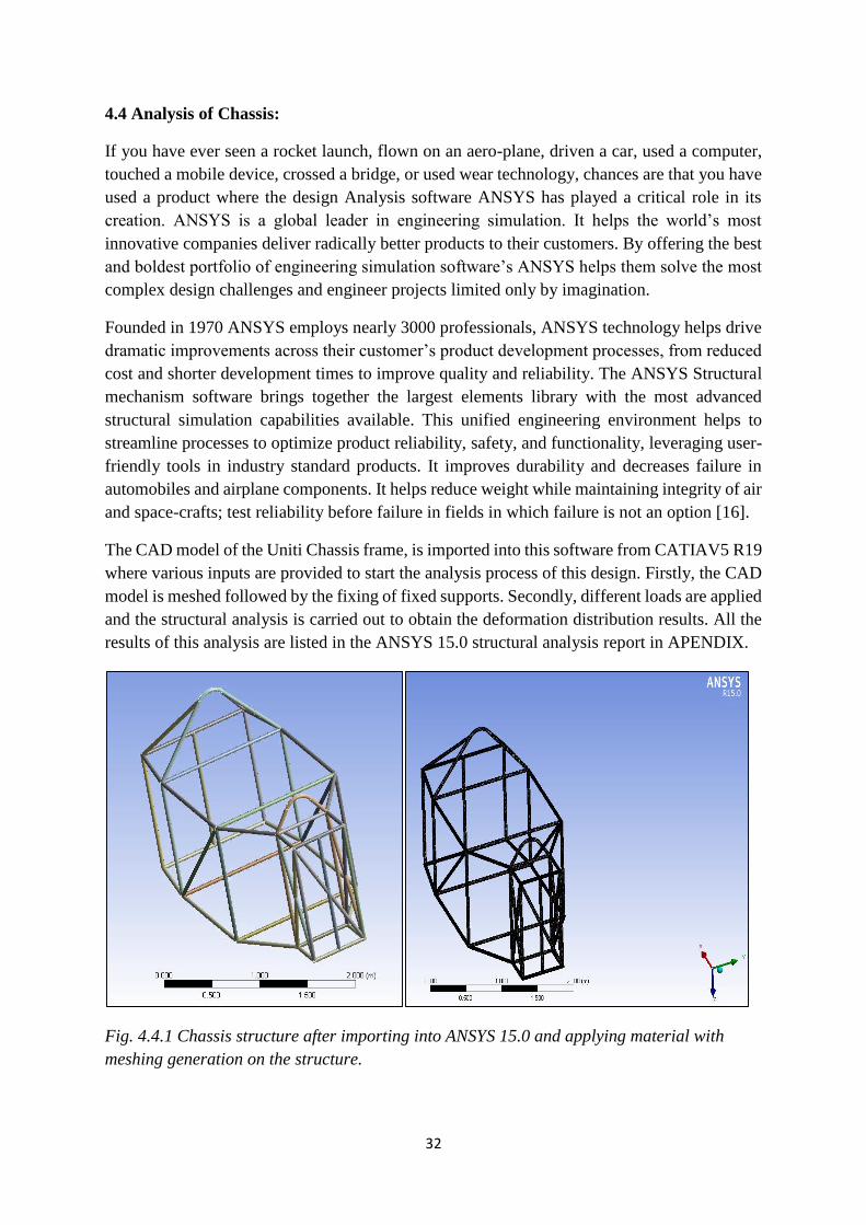
The CAD model of the Uniti Chassis frame, is imported into this software from CATIAV5 R19
where various inputs are provided to start the analysis process of this design. Firstly, the CAD
model is meshed followed by the fixing of fixed supports. Secondly, different loads are applied
and the structural analysis is carried out to obtain the deformation distribution results. All the
results of this analysis are listed in the ANSYS 15.0 structural analysis report in APENDIX.
Fig. 4.4.1 Chassis structure after importing into ANSYS 15.0 and applying material with
meshing generation on the structure.

33
Fig. 4.4.2 Applying of fixed support B (indicated by blue color)
Fig.4.4.3 Applying Forces A, C, D, E, F and H of 166.66 N each on the chassis structure
along with fixed support B

34
4.5 Static Structural Analysis
For a static chassis, a frontal impact force of 1000 N is applied. After applying this resultant
force of 1000 N we can observe the following chassis deformation.
Fig. 4.5.1 Deformation simulation of the chassis structural frame
Fig 4.5.2 Deformation distribution as observed in the chassis deformation simulation
After application of the various forces (A, C, D, E, F and H) of 166.66 N and therefore, a
resultant force of 1000N on the front of the chassis frame structure with fixed support B we
obtain the above deformation distribution showing us the effect of the frontal force’s impact
on the chassis frame and these results confirm us the static structural stability of our chassis
frame structure.

35
CHAPTER 5: CONCLUSION
An ideal chassis for the Uniti EV was designed and constructed using different Product
development methodologies and CAD & analysis softwares, as described and executed in the
thesis. The conclusion from these methodologies were used as inputs to design a suitable type
of chassis for Uniti EV.
The literature study was carried out for better understanding of the whole process of developing
a chassis. Various topics that are researched are listed below:
Types of chassis
Various loading conditions and types of Stresses acting on the Chassis
Materials used for chassis manufacturing
Advanced materials
Material Selection phenomenon
Selected Space Frame Chassis:
From the Pro- Con Analysis for chassis frames, Space frame has weighed pros over cons when
compared with different types of chassis, as it is a 3 dimensional chassis frame which has
managed to increase the bending strength and stiffness of the entire design. Thus we select
‘Space Frame chassis’ as the suitable chassis design.
From Quality Function Deployment (QFD) all the user expectations were listed, technical
specifications were prioritized and all those interdependent technical specifications were also
crossed checked. By comparing all the different frames in the QFD the Space frame got more
rating of 5 (table 4.1.1). Therefore the result from the QFD is Space Frame
Selected Carbon Fiber Composite Material for chassis:
From the Pro-Con Analysis for materials by compairing all the materials as of carbon fiber
composites are 3.8 times stronger than steel, 4.5 times stronger than aluminum alloys, 7.4 times
stronger than Titanium. It has exellent strength to weight ratio when compaired to other
materials. And it has good production flexibility as it can easliy be formed into complex shapes.
Along with this our design requirment and criteria was to select a sustainable material which
could suits the uniti EV. Thus, we select ‘Carbon fiber’ composite material for the manufacture
of the chassis structure. By comparing all the materials in the QFD Carbon fiber also got the
most rating of 5 table (table 4.2.1). So the result from the QFD is carbon fiber.
The dimensional specifications of Uniti EV helps us to design an accurate chassis structure.
The CAD and simulation software which used for drafting, designing, and analyzing are:
CATIA V5R19 and ANSYS 15.0.
Achieved the required chassis design for the Uniti EV, with accurate results for static structural
Analysis from ANSYS 15.0.

36
CHAPTER 6: CRITICAL REVIEW
The master thesis was initiated with the selection of the best type of vehicle chassis
frame and the material which would be most suitable for the manufacture of an L7e category
Electric vehicle. All this became possible only after we completed a comprehensive literature
study about the various types of chassis frames which are being used currently in the market
and the different types of materials used for their manufacture. By making use of the Pro- Con
analysis we could list the different merits and demerits of using the various types of chassis
frame designs and different material types.
With the generation of the House of Quality (also called Quality Function Deployment) gave
us various engineering specifications and solution towards choosing the ideal design suitable
for the Uniti EV. The QFD helped to develop technical requirements (or engineering
specifications) which were given numerical logic in the central block of the QFD, as we knew
what values to be given during the actual designing and analysis process of the chassis
structure. The CES EduPack software was made use in order find the best suitable material for
manufacturing the chassis frame. The final design became possible after carefully
implementing all various engineering specifications into the actual design in the CAD
(computer Aided Design) software.
During generation of the QFD a more comprehensive customer feedback market survey could
have given us better engineering specifications. The limited knowledge about the final design’s
dimensions during the design stage made it difficult for us to initiate the design process in the
initial stages. During the analysis stage the compatibility of the CAD file created using the
CAD software (CATIA V5R19) initially created minor issues while importing in to the analysis
software (ANSYS 15.0). The limited number of structural stability simulation tests carried out
might not have provided sufficient information regarding the structural stability of the chassis
frame.
When we started the analysis of our chassis frame design due to the time limitations and
compatibility issues of importing the CAD files from the different CAD software to Analysis
software resulted in us able to carry out only the very important static structural stability
analysis simulation test, which tested the static stability of our chassis frame structure, with
only one frontal load of 1000 N. More test could have provided us with better understanding
about the structural stability of our chassis frame structure.
Environmental and Sustainability concerns:
This project aims to develop the most suitable chassis frame structure for the L7e CP category
electric vehicle being developed by Uniti Sweden AB. At Uniti, our goal is to develop a new
vehicle for modern urban mobility. As we feel the existing automobile industry has failed to
recognize the importance of sustainable development and have befriended the environment.
Therefore, we have selected Carbon fiber as the material for the chassis over many other
materials considering this important aspect. Indeed, that might not be ideal for the environment
as Carbon fiber also has a significant carbon foot print, considering this we are still researching

37
the possibility of opting a hybrid material like Carbon-cellulose fiber composites considering
its better environmental aspect.
Health and Safety:
The health and safety is extremely important for any sustainable development. At Uniti we give
at most importance to this aspect as well. The Carbon fiber composite material used to
manufacture the chassis makes use of a Petroleum based resin material which might not be
biodegradable and could be toxic to the environment, thus could affect the health of the
personnel involved in its manufacturing process. Therefore, this again leads us to find more
sustainable and safe resin materials like bio based green resins which as more safe.
Economy:
When developing a vehicle that aims to change and revolutionize the entire auto industry by
giving extreme importance to sustainability and environmental concerns the cost of the vehicle
gets highly impacted. As we do not want to make cost the prime factor while selecting the
suitable material for manufacture, we have selected carbon fiber and space frame structure over
possible economical options such as plastic composite materials. Although carbon fiber
composites are highly expensive.
Ethical Aspects:
From the start of this project the one aspect that we value the most is this important aspect of
engineering ethics. We consider it as more important for engineering firms to reflect upon this
aspect more than for mere economic gains. We find this culture existing in the firm Uniti
Sweden AB which gives us more pleasure.
Our Master Thesis University supervisor Prof. Mr. Lars Bååth guided us to follow the
correct methodology throughout the entire thesis project. And our Industrial Supervisor, Mr.
Michael Bano helped us to follow the correct approach to carry out the literature study on
materials used for chassis manufacturing and to develop a better understanding about the
relevant current technologies and future materials under research. As of future study on this
regard we would be working for Uniti Sweden AB to develop better chassis frame designs with
numerous iterations so that they suit the new versions of Uniti EV.

38
CHAPTER 7: REFERENCES
1. David G. Ullman (2010) The Mechanical Design Process, Fourth Edition
2. CES EduPack Overview: Granta Design
URL:https://www.grantadesign.com/download/pdf/CES-Edupack-2016-Overview.pdf
3. Julian Happian-Smith (2002) An Introduction to Modern Vehicle Design
4. Mr. Birajdar M. D., Prof. Mulley. (2015) Design Modification of Ladder Chassis Frame
International Journal of Science, Engineering, and Technology Research (IJSETR),
Volume 4, Issue 10, p 3443- 3449
5. Backbone chassis Explained URL http://www.motor-car.co.uk/car-body/item/15086-
backbone-chassis
6. Perimeter Frame URL: http://www.bikes4sale.in/kb/motorcycle-frame.php
7. Backbone tube chassis URL: http://designthedesire.blogspot.se/2015/04/chassis.html
8. Sub-Frame Lamborghini Aventador LP 700-4 chassis
URL: http://www.flickr.com/photos/jsmith831/6099339034/ Lamborghini Aventador
LP 700-4 chassis Date=2011-08-30
9. Julian Happian-Smith (2002), An Introduction to Modern Vehicle Design (p 141)
10. Uni-body Frame URL: http://www.web2carz.com/autos/car-tech/2332/body-on-
frame-vs-unibody-construction
11. Ladder Frame URL: https://carsexplained.wordpress.com/2016/06/12/__trashed/
12. Elaheh Ghassemieh, Materials in Automotive Application State of the Art and Prospects
University of Sheffield UK, (p 373- 383)
13. Mark Wan, Different Types of Chassis Copyright© 1998-2000 by Auto Zine Technical
School URL: http://www.autozine.org/technical_school/chassis/tech_chassis.htm
14. Dr. Hossenein Saidpour (2004), Lightweight High Performance Materials for car body
Structures.
15. Pratik Patole (2015), Motorcycle Perimeter Frame- All You Need To Know URL:
http://www.bikesindia.org/reviews/motorcycle-perimeter-frame-all-you-need-to-
know.html
16. Sudhir Sharma, Director, High Tech Industry Marketing, ANSYS (2016) Excellence in
Engineering Simulation Advantage Special Edition URL:
https://www.google.se/url?sa=t&rct=j&q=&esrc=s&source=web&cd=3&cad=rja&uact=8
&ved=0ahUKEwi8scbz-
pfRAhWDWywKHfjIDl0QFggnMAI&url=http%3A%2F%2Fresource.ansys.com%2Fsta
ticassets%2FANSYS%2Fstaticassets%2Fresourcelibrary%2Farticle%2FANSYS-
Advantage-Best-of-High-Tech-AA-
2016.pdf&usg=AFQjCNHsADNJPxChDyG4cE8gPNnDhhC6_A&sig2=G-
ti6e3kxNmfogs9UnnGrg
Miscellaneous References:
17. R. K. Rajput (2001) A Text Book of Automobile Engineering
18. Automobile Chassis and Frame
URL:http://engineeringpsycho.blogspot.se/2016/02/automobile-chassis-and-
frame.html
19. David A Crolla (2001), Automotive Engineering, Powertrain, Chassis system and
vehicle Body
20. Edwald Schmitt and Elisabeth Lange (2011), Chassis Handbook- Fundamentals,
Driving Dynamics, Components, Mechatronics, Perspectives

39
21. William B. Riley and Albert R. George, Cornell University (2001) Design, Analysis,
and Testing of a Formula SAE car Chassis.
22. Prof. Dipl.-Ing. Johnsen Reimpell, Dipl.-Ing. Helmut Stoll, Prof. Dr. -Jurgen W. Betzler
(2002), The Automotive Chassis Principles Second Edition
23. Sri N.R. Hema Kumar, A Text book on Automotive Chassis and Body Engineering.
40
CHAPTER 8: APPENDIX
Different types of Load conditions on chassis:
Momentary loads acting on chassis - while taking a turn on a curved road
Impact load on chassis- due to collision of vehicles.
Inertia load – while applying brakes
Static load- loads due to chassis part
Over loads- loads applied beyond the design conditions
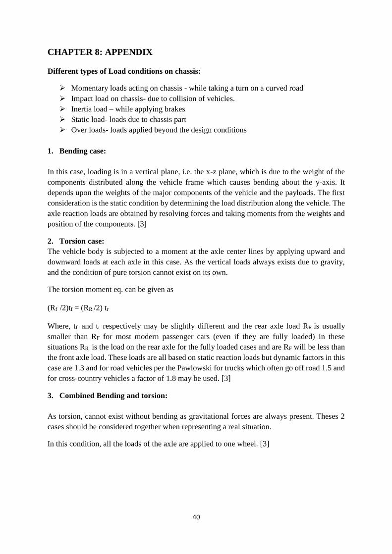
1. Bending case:
In this case, loading is in a vertical plane, i.e. the x-z plane, which is due to the weight of the
components distributed along the vehicle frame which causes bending about the y-axis. It
depends upon the weights of the major components of the vehicle and the payloads. The first
consideration is the static condition by determining the load distribution along the vehicle. The
axle reaction loads are obtained by resolving forces and taking moments from the weights and
position of the components. [3]
2. Torsion case:
The vehicle body is subjected to a moment at the axle center lines by applying upward and
downward loads at each axle in this case. As the vertical loads always exists due to gravity,
and the condition of pure torsion cannot exist on its own.
The torsion moment eq. can be given as
(Rf /2)tf = (RR /2) tr
Where, tf and tr respectively may be slightly different and the rear axle load RR is usually
smaller than RF for most modern passenger cars (even if they are fully loaded) In these
situations RR is the load on the rear axle for the fully loaded cases and are RF will be less than
the front axle load. These loads are all based on static reaction loads but dynamic factors in this
case are 1.3 and for road vehicles per the Pawlowski for trucks which often go off road 1.5 and
for cross-country vehicles a factor of 1.8 may be used. [3]
3. Combined Bending and torsion:
As torsion, cannot exist without bending as gravitational forces are always present. Theses 2
cases should be considered together when representing a real situation.
In this condition, all the loads of the axle are applied to one wheel. [3]

41
If the left front wheel had been lifted instead of the right rear wheel the same situation would
have occurred.ie, the left rear wheel load will reduce to zero before the right front wheel. Any
further lifting of the left front wheel (or right rear wheel) will not increase the torque applied
to the vehicle structure. [3]
4. Lateral loading:
It happens when a vehicle is driven around a corner or when the vehicle slides against a
sidewalk or pavement i.e. the load acting on the y-axis.
Let us consider the case of cornering, in this situation lateral loads are generated at the tyre to
ground contact patches. Centrifugal forces balance theses patches i.e., MV2/R [3]

42
Let us consider the situation when the wheel reaction on the inside of the turn drops to zero,
i.e. when the vehicle rolls over. This condition the vehicle structure is subjected to bending in
the x-y plane. This condition also depends upon the height of the vehicle center of gravity and
track. At this condition the resultant of the centrifugal force and the weight passes through the
outside wheels contact patch. [3]
MV2
𝑅(h)=Mg (
𝑡
2)
Lateral acceleration 𝑀𝑉2
𝑅 h = Mg
𝑡
2 …………………………………….1
The lateral forces at the center of gravity
𝑀𝑉2
𝑅 =
Mg t
2ℎ…………………………..A
The side forces at front tyre
YF = Mg t
2ℎ (
𝑏
𝑎+𝑏)…………………….2
At rear tyre,
YR = 𝑀𝑔𝑡
2ℎ (
𝑎
(𝑎+𝑏))…………………..3
Now the structure can be considered as a simply supported beam subject to lateral loading in
xy plane through the Centre of gravity.
Normal driving conditions never approach this situation because when height h (the height of
the center of gravity from a road surface datum.)
A modern car is typically 0.51m and track is 1.45m.
Lateral acceleration = 𝑔𝑡
2ℎ=
𝑔(1.45)
2(0.51)= 1.42 g
From equations 1 & A
We get, the lateral acceleration is 1.42 times of gravitational acceleration.
Note:
This does not occur as conventional road tyre side forces limit lateral acceleration to about is
0.75g. [3]
5. Fore and aft loading (Longitudinal loading):
During the acceleration and braking longitudinal forces are generated along the x-axis.
If the Centre of gravity of the vehicle is above the road surface the inertia force provides a load
transfer from one axle to another. While accelerating, the weight is transferred from front to
rear axle and vice versa for breaking or decelerating condition. To obtain a complete view of
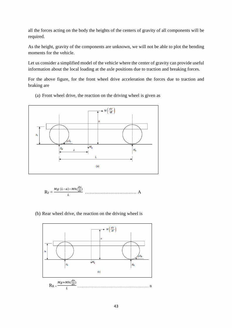
43
all the forces acting on the body the heights of the centers of gravity of all components will be
required.
As the height, gravity of the components are unknown, we will not be able to plot the bending
moments for the vehicle.
Let us consider a simplified model of the vehicle where the center of gravity can provide useful
information about the local loading at the axle positions due to traction and breaking forces.
For the above figure, for the front wheel drive acceleration the forces due to traction and
braking are
(a) Front wheel drive, the reaction on the driving wheel is given as
RF = 𝑀𝑔 (𝐿−𝑎)−𝑀ℎ(
𝑑𝑣
𝑑𝑡)
𝐿 …………………………… A
(b) Rear wheel drive, the reaction on the driving wheel is
RR =
𝑀𝑔+𝑀ℎ(𝑑𝑣
𝑑𝑡)
𝐿 …………………………………………………………… B

44
(c) Braking case, the reaction on the axle are:
RF =
𝑀𝑔(𝐿−𝑎)+𝑀ℎ(𝑑𝑣
𝑑𝑡)
𝐿 ………………………………………………….C
6. Asymmetric Loading:
This type of loading occurs when one wheel strikes a raised object or drops into a hole that has
a raised edge. The resulting loads are vertical and longitudinal applied at one corner of the
vehicle. This condition is very complex loading on the entire vehicle structure. The magnitude
of the force excreted on the wheel and hence throughout the suspension to the structure will
depend upon [3]
Vehicle speed
Suspension stiffness
Wheel mass
Body mass
As the shock force is applied for a very period it can be assumed that the wheel continuous in
a steady speed. Therefore, the shock force Ru acts through the wheel center
The horizontal component will be
Rux = Ru Cos α
The vertical component will be
Ruz = Ru Sin α

45
The angle α is approximately
α = Sin-1 (rd-hu)/rd
Note: Assuming the tyre does not deflect excessively, the horizontal component will increase
relative to the vertical for small radius wheels.
Considering, the vertical loads on its own causes an additional axle load, inertial load through
the vehicle center of mass and a torsion moment on the vehicle structure.
Similarly, considering horizontal loads on its own as seeing the above figure (c) the addition
bending in the vertical plane x-z and a moment about the z axis are applied to the structure.
Hence, from the structural loading this load can be analyzed by the superposition of the 4 load
conditions. [3]
CES EduPack Results:
Density Vs. Tensile Strength:

46
By comparing the material properties of Density and Tensile strengths of, High Carbon Steel,
Age-hardening wrought Al alloy, Wrought Magnesium Alloy, Polyester, glass fiber reinforced
polymer epoxy matrix, carbon fiber reinforced plastics epoxy matrix for manufacture of the
structural chassis frame, we observed from the above graph that the material high carbon steel
has the highest density and tensile strength when compared with the rest of the materials but
as it is very heavy when compared to the rest of the materials. Hence, we do not select High
Carbon steel as the best suitable material for manufacture of the structural chassis frame.
In the same way polyester, can be observed as having the least density and tensile strength is
also not preferred as to be selected as the best material for manufacture of the chassis frame.
After careful study of these results we have concluded that Carbon fiber reinforced plastics
epoxy matrix is the best suitable material for manufacture of the structural frame of the chassis
as it has the ideal density, tensile strength, and weight.
Compressive Strength Vs. Price (SEK):
By comparing the compressive strength and price in SEK for all materials listed above we can
observe that High carbon steel has the least price in SEK and with most compressive strength,
but due to its other numerous demerits as observed above make it not the ideal material for
selection for manufacture of the structural chassis frame. After carefully analyzing all these
materials, based on their properties and price in SEK we select Carbon fiber reinforced plastics
as the ideal material for manufacture of the structural chassis frame.

47
Project
First Saved Wednesday, October 26, 2016
Last Saved Wednesday, October 26, 2016
Product Version 15.0 Release
Save Project Before Solution No
Save Project After Solution No
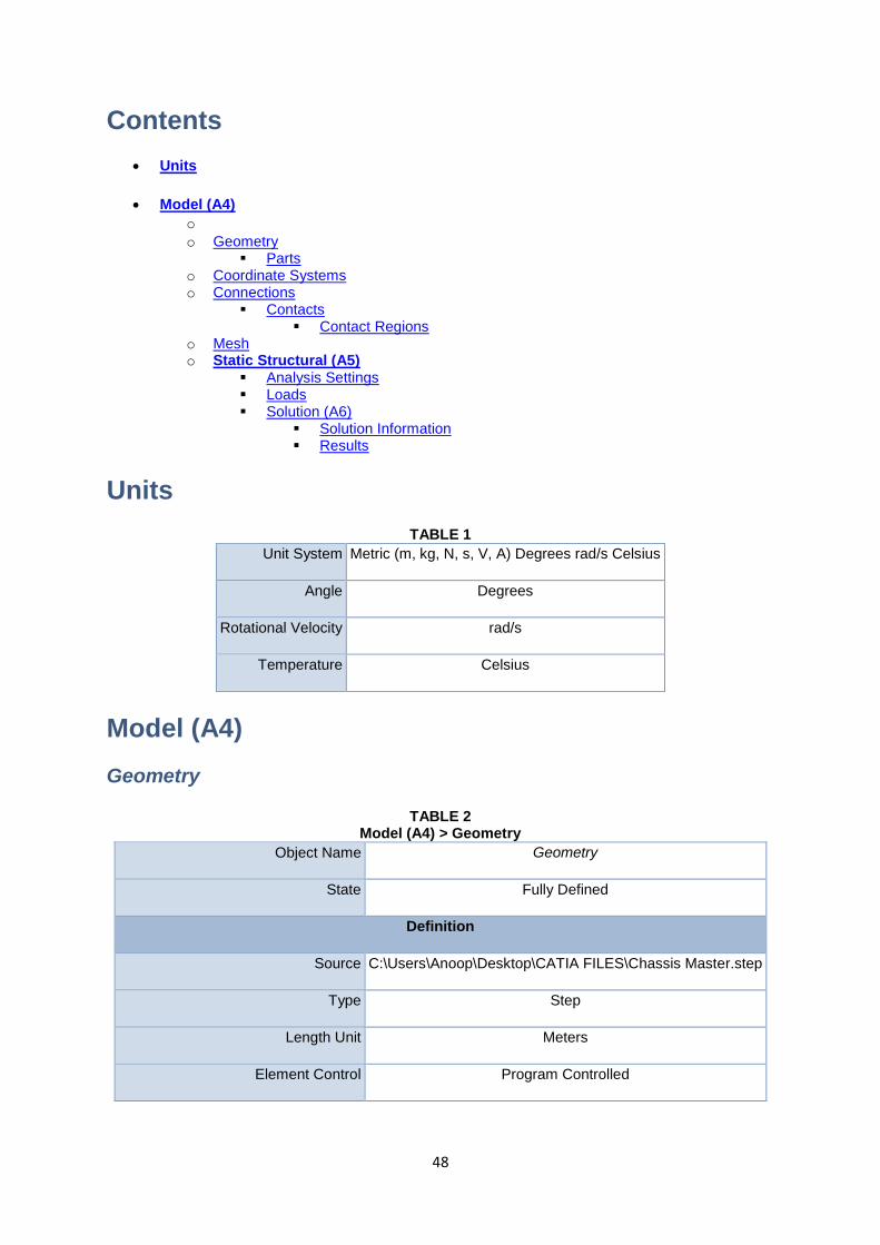
48
Contents
Units
Model (A4) o o Geometry
Parts o Coordinate Systems o Connections
Contacts Contact Regions
o Mesh o Static Structural (A5)
Analysis Settings Loads Solution (A6)
Solution Information Results
Units
TABLE 1
Unit System Metric (m, kg, N, s, V, A) Degrees rad/s Celsius
Angle Degrees
Rotational Velocity rad/s
Temperature Celsius
Model (A4)
Geometry
TABLE 2 Model (A4) > Geometry
Object Name Geometry
State Fully Defined
Definition
Source C:\Users\Anoop\Desktop\CATIA FILES\Chassis Master.step
Type Step
Length Unit Meters
Element Control Program Controlled

49
Display Style Body Color
Bounding Box
Length X 2.791 m
Length Y 1.48 m
Length Z 2.0994 m
Properties
Volume 0.11483 m³
Mass 901.38 kg
Scale Factor Value 1.
Statistics
Bodies 25
Active Bodies 25
Nodes 275471
Elements 183583
Mesh Metric None
Basic Geometry Options
Solid Bodies Yes
Surface Bodies Yes
Line Bodies No
Parameters Yes
Parameter Key DS
Attributes No
Named Selections No
Material Properties No
Advanced Geometry Options
Use Associativity Yes
Coordinate Systems No

50
Reader Mode Saves Updated File No
Use Instances Yes
Smart CAD Update No
Compare Parts on Update No
Attach File Via Temp File Yes
Temporary Directory C:\Users\Anoop\AppData\Local\Temp
Analysis Type 3-D
Mixed Import Resolution None
Decompose Disjoint Geometry Yes
Enclosure and Symmetry Processing Yes
TABLE 3 Model (A4) > Geometry > Parts
Object
Name
Chassi
s
Master
s v2 v1
Chassi
s
Master
s v2 v1
Chass
is
Maste
rs v2
v1
Chassi
s
Master
s v2 v1
Chassi
s
Master
s v2 v1
Chass
is
Maste
rs v2
v1
Chass
is
Maste
rs v2
v1
Chassi
s
Master
s v2 v1
Chass
is
Maste
rs v2
v1
Chass
is
Maste
rs v2
v1
Chass
is
Maste
rs v2
v1
State Meshed
Graphics Properties
Visible Yes
Transpare
ncy 1
Definition
Suppresse
d No
Stiffness
Behavior Flexible
Coordinate
System Default Coordinate System
Reference
Temperatu
re
By Environment
Thickness 2.e-002 m

51
Thickness
Mode Manual
Offset
Type Middle
Material
Assignmen
t Carbon Fiber
Nonlinear
Effects Yes
Thermal
Strain
Effects
Yes
Bounding Box
Length X 4.e-002 m 0.65841 m 4.e-002 m 1.2195 m
Length Y 4.e-002 m 0.64 m 1.48 m 0.51981 m 4.e-002 m
Length Z 1.3035 m 1.6196
m
2.0794
m 2.0136 m 1.3035 m 1.3305 m
Properties
Volume 3.2743e-003 m³
8.7551
e-003
m³
1.1879
e-002
m³
5.9124e-003
m³
3.2743e-003
m³
4.4336e-003
m³
Mass 25.704 kg 68.728
kg
93.248
kg 46.412 kg 25.704 kg 34.804 kg
Centroid X
5.3932
e-019
m
1.2446
e-019
m
2.987
e-018
m
0.3680
1 m
2.1287
m 2.6122 m
2.751
m
0.938
7 m 1.5337 m
Centroid Y -0.3 m 0. m 0.3 m
6.3999
e-006
m
1.4033
e-005
m
-
0.505
8 m
0.505
8 m
-
8.2972
e-019
m
0.72 m -0.72
m
Centroid Z 0.65176 m 0.444
m
0.1792
1 m 0.20587 m 0.65176 m
Moment of
Inertia Ip1 3.6362 kg·m²
21.421
kg·m²
69.195
kg·m² 17.872 kg·m² 3.6362 kg·m² 9.0211 kg·m²
Moment of
Inertia Ip2 3.6362 kg·m²
16.207
kg·m²
35.029
kg·m² 18.74 kg·m² 3.6362 kg·m² 9.0211 kg·m²
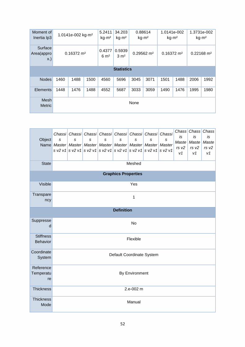
52
Moment of
Inertia Ip3 1.0141e-002 kg·m²
5.2411
kg·m²
34.203
kg·m²
0.88614
kg·m²
1.0141e-002
kg·m²
1.3731e-002
kg·m²
Surface
Area(appro
x.)
0.16372 m² 0.4377
6 m²
0.5939
3 m² 0.29562 m² 0.16372 m² 0.22168 m²
Statistics
Nodes 1460 1488 1500 4560 5696 3045 3071 1501 1488 2006 1992
Elements 1448 1476 1488 4552 5687 3033 3059 1490 1476 1995 1980
Mesh
Metric None
Object
Name
Chassi
s
Master
s v2 v1
Chassi
s
Master
s v2 v1
Chassi
s
Master
s v2 v1
Chassi
s
Master
s v2 v1
Chassi
s
Master
s v2 v1
Chassi
s
Master
s v2 v1
Chassi
s
Master
s v2 v1
Chassi
s
Master
s v2 v1
Chass
is
Maste
rs v2
v1
Chass
is
Maste
rs v2
v1
Chass
is
Maste
rs v2
v1
State Meshed
Graphics Properties
Visible Yes
Transpare
ncy 1
Definition
Suppresse
d No
Stiffness
Behavior Flexible
Coordinate
System Default Coordinate System
Reference
Temperatu
re
By Environment
Thickness 2.e-002 m
Thickness
Mode Manual

53
Offset
Type Middle
Material
Assignme
nt Carbon Fiber
Nonlinear
Effects Yes
Thermal
Strain
Effects
Yes
Bounding Box
Length X 4.e-002 m 0.4065
1 m 4.e-002 m 0.40651 m
Length Y 1.44 m 4.e-
002 m 1.44 m
4.e-
002 m 0.6 m
0.6363
4 m 1.44 m 4.e-002 m
Length Z 4.e-
002 m
1.3035
m
4.e-
002 m
1.3144
m
4.e-
002 m
1.3202
m 4.e-002 m 1.3144 m
Properties
Volume
3.6172
e-003
m³
3.2743
e-003
m³
3.6172
e-003
m³
3.4023
e-003
m³
1.5072
e-003
m³
3.6046
e-003
m³
3.6172e-003
m³ 3.4023e-003 m³
Mass 28.395
kg
25.704
kg
28.395
kg
26.708
kg
11.831
kg
28.296
kg 28.395 kg 26.708 kg
Centroid X 2.1287
m 0.9387 m
0.1840
1 m
0.3680
1 m
-
3.5337
e-011
m
2.1287
m
0.9387
m 0.18401 m
Centroid Y
1.3099
e-016
m
-0.72
m
5.4078
e-018
m
0.3 m
-
5.4078
e-018
m
1.2257
e-009
m
1.3219
e-017
m
3.0043
e-018
m
0.3 m -0.3 m
Centroid Z 1.3035
m
0.6517
6 m
1.3035
m
0.6517
6 m
1.3035
m
0.6517
6 m
3.7554
e-019
m
2.2533
e-019
m
0.65176 m
Moment of
Inertia Ip1
4.9009
kg·m²
3.6362
kg·m²
4.9009
kg·m²
4.0791
kg·m²
0.3564
5
kg·m²
4.8498
kg·m² 4.9009 kg·m² 4.0791 kg·m²
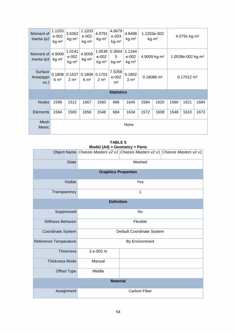
54
Moment of
Inertia Ip2
1.1203
e-002
kg·m²
3.6362
kg·m²
1.1203
e-002
kg·m²
4.0791
kg·m²
4.6679
e-003
kg·m²
4.8498
kg·m²
1.1203e-002
kg·m² 4.0791 kg·m²
Moment of
Inertia Ip3
4.9009
kg·m²
1.0141
e-002
kg·m²
4.9009
kg·m²
1.0538
e-002
kg·m²
0.3564
5
kg·m²
1.1164
e-002
kg·m²
4.9009 kg·m² 1.0538e-002 kg·m²
Surface
Area(appr
ox.)
0.1808
6 m²
0.1637
2 m²
0.1808
6 m²
0.1701
2 m²
7.5358
e-002
m²
0.1802
3 m² 0.18086 m² 0.17012 m²
Statistics
Nodes 1596 1512 1667 1560 696 1645 1584 1620 1560 1621 1684
Elements 1584 1500 1656 1548 684 1634 1572 1608 1548 1610 1673
Mesh
Metric None
TABLE 5 Model (A4) > Geometry > Parts
Object Name Chassis Masters v2 v1 Chassis Masters v2 v1 Chassis Masters v2 v1
State Meshed
Graphics Properties
Visible Yes
Transparency 1
Definition
Suppressed No
Stiffness Behavior Flexible
Coordinate System Default Coordinate System
Reference Temperature By Environment
Thickness 2.e-002 m
Thickness Mode Manual
Offset Type Middle
Material
Assignment Carbon Fiber
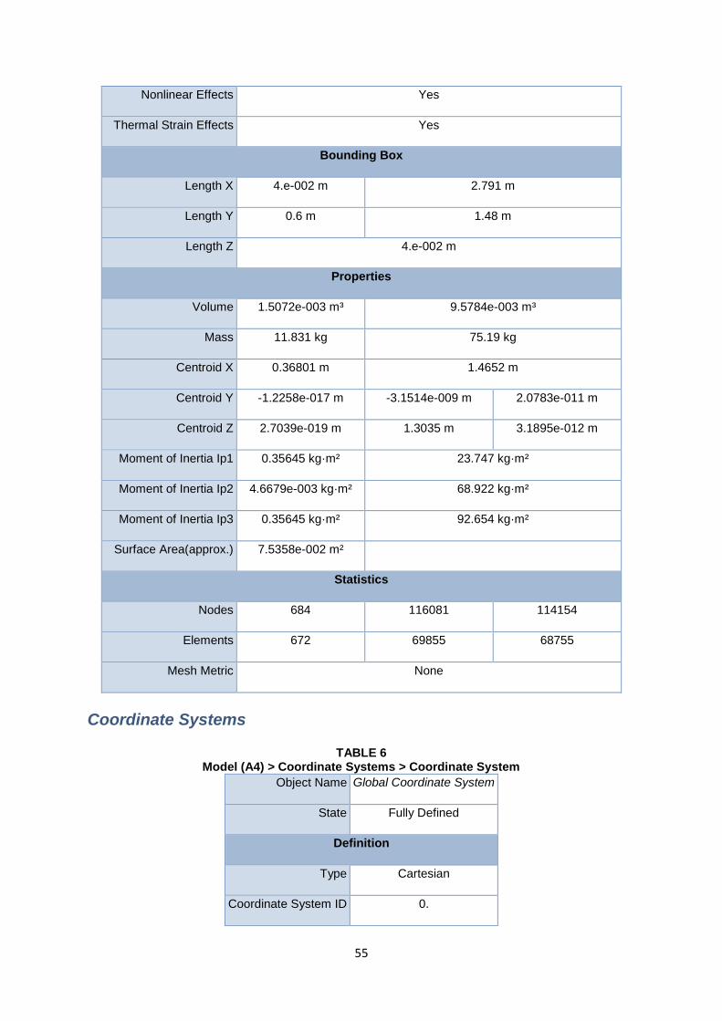
55
Nonlinear Effects Yes
Thermal Strain Effects Yes
Bounding Box
Length X 4.e-002 m 2.791 m
Length Y 0.6 m 1.48 m
Length Z 4.e-002 m
Properties
Volume 1.5072e-003 m³ 9.5784e-003 m³
Mass 11.831 kg 75.19 kg
Centroid X 0.36801 m 1.4652 m
Centroid Y -1.2258e-017 m -3.1514e-009 m 2.0783e-011 m
Centroid Z 2.7039e-019 m 1.3035 m 3.1895e-012 m
Moment of Inertia Ip1 0.35645 kg·m² 23.747 kg·m²
Moment of Inertia Ip2 4.6679e-003 kg·m² 68.922 kg·m²
Moment of Inertia Ip3 0.35645 kg·m² 92.654 kg·m²
Surface Area(approx.) 7.5358e-002 m²
Statistics
Nodes 684 116081 114154
Elements 672 69855 68755
Mesh Metric None
Coordinate Systems
TABLE 6 Model (A4) > Coordinate Systems > Coordinate System
Object Name Global Coordinate System
State Fully Defined
Definition
Type Cartesian
Coordinate System ID 0.

56
Origin
Origin X 0. m
Origin Y 0. m
Origin Z 0. m
Directional Vectors
X Axis Data [ 1. 0. 0. ]
Y Axis Data [ 0. 1. 0. ]
Z Axis Data [ 0. 0. 1. ]
Connections
TABLE 7 Model (A4) > Connections
Object Name Connections
State Fully Defined
Auto Detection
Generate Automatic Connection On Refresh Yes
Transparency
Enabled Yes
TABLE 8 Model (A4) > Connections > Contacts
Object Name Contacts
State Fully Defined
Definition
Connection Type Contact
Scope
Scoping Method Geometry Selection
Geometry All Bodies
Auto Detection
Tolerance Type Slider

57
Tolerance Slider 0.
Tolerance Value 9.4827e-003 m
Use Range No
Face/Face Yes
Face/Edge No
Edge/Edge No
Priority Include All
Group By Bodies
Search Across Bodies
TABLE 9 Model (A4) > Connections > Contacts > Contact Regions
Object
Name
Conta
ct
Regio
n
Conta
ct
Regio
n 2
Conta
ct
Regio
n 3
Conta
ct
Regio
n 4
Conta
ct
Regio
n 5
Contact
Region 6
Conta
ct
Regio
n 7
Conta
ct
Regio
n 8
Conta
ct
Regio
n 9
Conta
ct
Regio
n 10
Conta
ct
Regio
n 11
State Fully Defined
Scope
Scoping
Method Geometry Selection
Contact 1 Face
Target 1 Face 2 Faces 1 Face
Contact
Bodies Chassis Masters v2 v1
Target
Bodies Chassis Masters v2 v1
Contact
Shell
Face
Program Controlled
Target
Shell
Face
Program Controlled
Program
Controlle
d
Program Controlled
Shell
Thickness
Effect
No

58
Definition
Type Bonded
Scope
Mode Automatic
Behavior Program Controlled
Trim
Contact Program Controlled
Trim
Tolerance 9.4827e-003 m
Suppress
ed No
Advanced
Formulati
on Program Controlled
Detection
Method Program Controlled
Penetratio
n
Tolerance
Program Controlled
Elastic
Slip
Tolerance
Program Controlled
Normal
Stiffness Program Controlled
Update
Stiffness Program Controlled
Pinball
Region Program Controlled
Geometric Modification
Contact
Geometry
Correction
None
TABLE 10 Model (A4) > Connections > Contacts > Contact Regions

59
Object
Name
Conta
ct
Regio
n 12
Conta
ct
Regio
n 13
Conta
ct
Regio
n 14
Conta
ct
Regio
n 15
Conta
ct
Regio
n 16
Conta
ct
Regio
n 17
Conta
ct
Regio
n 18
Conta
ct
Regio
n 19
Conta
ct
Regio
n 20
Conta
ct
Regio
n 21
Contact
Region
22
State Fully Defined
Scope
Scoping
Method Geometry Selection
Contact 1 Face 2 Faces 1
Face
4
Faces
2
Faces
4
Faces 3 Faces
Target 2 Faces 1 Face 4 Faces 1 Face
Contact
Bodies Chassis Masters v2 v1
Target
Bodies Chassis Masters v2 v1
Contact
Shell
Face
Program Controlled
Shell
Thickness
Effect
No
Target
Shell
Face
Program Controlled
Program
Controlle
d
Definition
Type Bonded
Scope
Mode Automatic
Behavior Program Controlled
Trim
Contact Program Controlled
Trim
Tolerance 9.4827e-003 m
Suppress
ed No

60
Advanced
Formulati
on Program Controlled
Detection
Method Program Controlled
Penetratio
n
Tolerance
Program Controlled
Elastic
Slip
Tolerance
Program Controlled
Normal
Stiffness Program Controlled
Update
Stiffness Program Controlled
Pinball
Region Program Controlled
Geometric Modification
Contact
Geometry
Correction
None
TABLE 11 Model (A4) > Connections > Contacts > Contact Regions
Object
Name
Conta
ct
Regio
n 23
Conta
ct
Regio
n 24
Conta
ct
Regio
n 25
Conta
ct
Regio
n 26
Conta
ct
Regio
n 27
Conta
ct
Regio
n 28
Conta
ct
Regio
n 29
Conta
ct
Regio
n 30
Conta
ct
Regio
n 31
Conta
ct
Regio
n 32
Conta
ct
Regio
n 33
State Fully Defined
Scope
Scoping
Method Geometry Selection
Contact 3
Faces 1 Face
2
Faces
4
Faces
2
Faces
4
Faces 1 Face
2
Faces 1 Face
2
Faces
Target 1 Face 4 Faces 2 Faces
Contact
Bodies Chassis Masters v2 v1

61
Target
Bodies Chassis Masters v2 v1
Contact
Shell Face Program Controlled
Target
Shell Face Program Controlled
Shell
Thickness
Effect
No
Definition
Type Bonded
Scope
Mode Automatic
Behavior Program Controlled
Trim
Contact Program Controlled
Trim
Tolerance 9.4827e-003 m
Suppresse
d No
Advanced
Formulatio
n Program Controlled
Detection
Method Program Controlled
Penetratio
n
Tolerance
Program Controlled
Elastic
Slip
Tolerance
Program Controlled
Normal
Stiffness Program Controlled
Update
Stiffness Program Controlled

62
Pinball
Region Program Controlled
Geometric Modification
Contact
Geometry
Correction
None
TABLE 12 Model (A4) > Connections > Contacts > Contact Regions
Object
Name
Conta
ct
Regio
n 34
Conta
ct
Regio
n 35
Conta
ct
Regio
n 36
Conta
ct
Regio
n 37
Conta
ct
Regio
n 38
Conta
ct
Regio
n 39
Conta
ct
Regio
n 40
Conta
ct
Regio
n 41
Conta
ct
Regio
n 42
Conta
ct
Regio
n 43
Conta
ct
Regio
n 44
State Fully Defined
Scope
Scoping
Method Geometry Selection
Contact 1 Face
Target 1 Face 2 Faces 1 Face 2 Faces
Contact
Bodies Chassis Masters v2 v1
Target
Bodies Chassis Masters v2 v1
Contact
Shell Face Program Controlled
Shell
Thickness
Effect
No
Target
Shell Face Program Controlled
Program
Controlled
Definition
Type Bonded
Scope
Mode Automatic
Behavior Program Controlled

63
Trim
Contact Program Controlled
Trim
Tolerance 9.4827e-003 m
Suppresse
d No
Advanced
Formulatio
n Program Controlled
Detection
Method Program Controlled
Penetratio
n
Tolerance
Program Controlled
Elastic
Slip
Tolerance
Program Controlled
Normal
Stiffness Program Controlled
Update
Stiffness Program Controlled
Pinball
Region Program Controlled
Geometric Modification
Contact
Geometry
Correction
None
TABLE 13 Model (A4) > Connections > Contacts > Contact Regions
Object
Name
Conta
ct
Regio
n 45
Conta
ct
Regio
n 46
Conta
ct
Regio
n 47
Conta
ct
Regio
n 48
Conta
ct
Regio
n 49
Conta
ct
Regio
n 50
Conta
ct
Regio
n 51
Conta
ct
Regio
n 52
Conta
ct
Regio
n 53
Conta
ct
Regio
n 54
Conta
ct
Regio
n 55
State Fully Defined
Scope

64
Scoping
Method Geometry Selection
Contact 1 Face
Target 1 Face 2 Faces 4
Faces 1 Face 2 Faces
4
Faces
Contact
Bodies Chassis Masters v2 v1
Target
Bodies Chassis Masters v2 v1
Contact
Shell Face Program Controlled
Target
Shell Face Program Controlled
Program
Controlled
Shell
Thickness
Effect
No
Definition
Type Bonded
Scope
Mode Automatic
Behavior Program Controlled
Trim
Contact Program Controlled
Trim
Tolerance 9.4827e-003 m
Suppresse
d No
Advanced
Formulatio
n Program Controlled
Detection
Method Program Controlled
Penetratio
n
Tolerance
Program Controlled

65
Elastic
Slip
Tolerance
Program Controlled
Normal
Stiffness Program Controlled
Update
Stiffness Program Controlled
Pinball
Region Program Controlled
Geometric Modification
Contact
Geometry
Correction
None
TABLE 14 Model (A4) > Connections > Contacts > Contact Regions
Object
Name
Conta
ct
Regio
n 56
Conta
ct
Regio
n 57
Conta
ct
Regio
n 58
Conta
ct
Regio
n 59
Contact
Region
60
Conta
ct
Regio
n 61
Conta
ct
Regio
n 62
Conta
ct
Regio
n 63
Conta
ct
Regio
n 64
Conta
ct
Regio
n 65
Conta
ct
Regio
n 66
State Fully Defined
Scope
Scoping
Method Geometry Selection
Contact 1 Face
Target 1 Face 2 Faces 1 Face 4
Faces 1 Face 2 Faces
4
Faces
Contact
Bodies Chassis Masters v2 v1
Target
Bodies Chassis Masters v2 v1
Contact
Shell
Face
Program Controlled
Target
Shell
Face
Program
Controlled
Program
Controlle
d
Program
Controlled
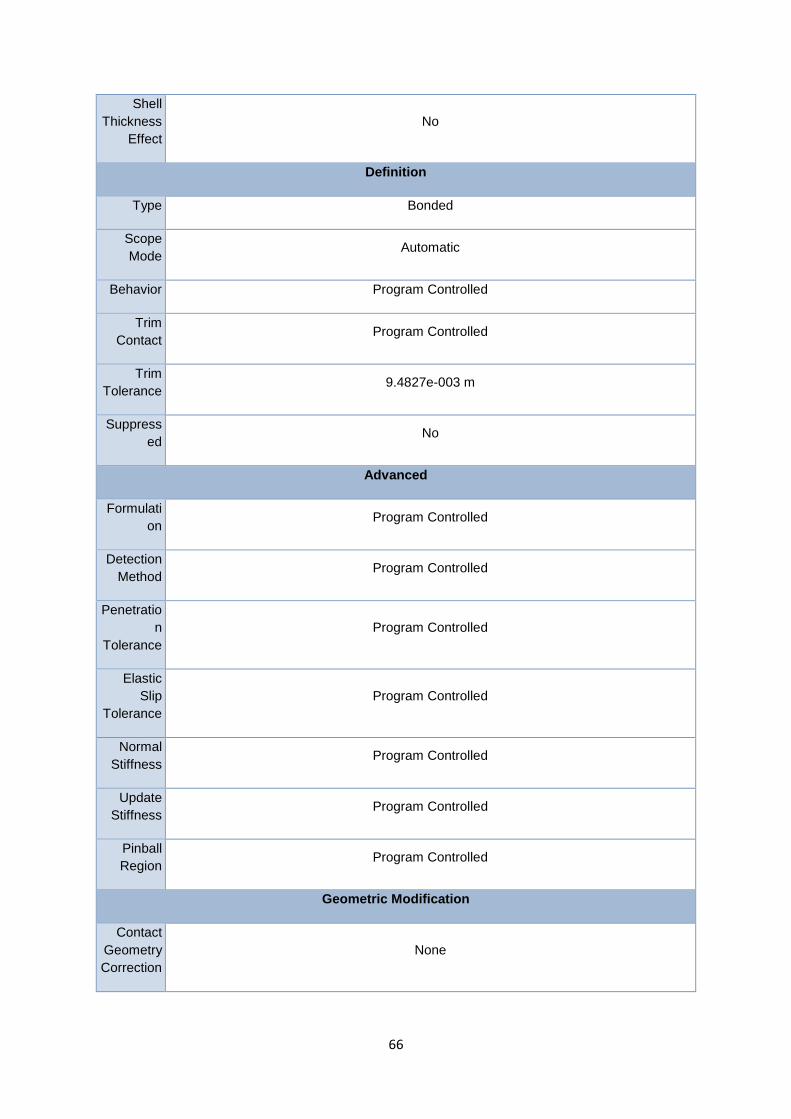
66
Shell
Thickness
Effect
No
Definition
Type Bonded
Scope
Mode Automatic
Behavior Program Controlled
Trim
Contact Program Controlled
Trim
Tolerance 9.4827e-003 m
Suppress
ed No
Advanced
Formulati
on Program Controlled
Detection
Method Program Controlled
Penetratio
n
Tolerance
Program Controlled
Elastic
Slip
Tolerance
Program Controlled
Normal
Stiffness Program Controlled
Update
Stiffness Program Controlled
Pinball
Region Program Controlled
Geometric Modification
Contact
Geometry
Correction
None

67
TABLE 15 Model (A4) > Connections > Contacts > Contact Regions
Object
Name
Conta
ct
Regio
n 67
Contact
Region
68
Conta
ct
Regio
n 69
Conta
ct
Regio
n 70
Conta
ct
Regio
n 71
Conta
ct
Regio
n 72
Conta
ct
Regio
n 73
Conta
ct
Regio
n 74
Conta
ct
Regio
n 75
Conta
ct
Regio
n 76
Conta
ct
Regio
n 77
State Fully Defined
Scope
Scoping
Method Geometry Selection
Contact 1 Face
Target 4
Faces 1 Face 2 Faces 1 Face 2 Faces
4
Faces
Contact
Bodies Chassis Masters v2 v1
Target
Bodies Chassis Masters v2 v1
Contact
Shell
Face
Program Controlled
Shell
Thickness
Effect
No
Target
Shell
Face
Program
Controlle
d
Program
Controlled
Definition
Type Bonded
Scope
Mode Automatic
Behavior Program Controlled
Trim
Contact Program Controlled
Trim
Tolerance 9.4827e-003 m
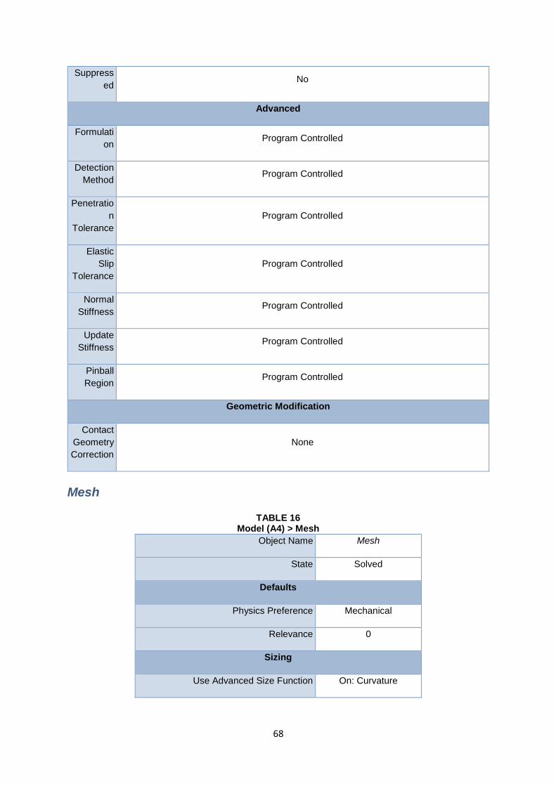
68
Suppress
ed No
Advanced
Formulati
on Program Controlled
Detection
Method Program Controlled
Penetratio
n
Tolerance
Program Controlled
Elastic
Slip
Tolerance
Program Controlled
Normal
Stiffness Program Controlled
Update
Stiffness Program Controlled
Pinball
Region Program Controlled
Geometric Modification
Contact
Geometry
Correction
None
Mesh
TABLE 16 Model (A4) > Mesh
Object Name Mesh
State Solved
Defaults
Physics Preference Mechanical
Relevance 0
Sizing
Use Advanced Size Function On: Curvature

69
Relevance Center Coarse
Initial Size Seed Active Assembly
Smoothing Medium
Transition Fast
Span Angle Center Coarse
Curvature Normal Angle Default (30.0 °)
Min Size Default (8.7157e-003 m)
Max Face Size Default (4.3579e-002 m)
Max Size Default (4.3579e-002 m)
Growth Rate Default
Minimum Edge Length 6.2832e-002 m
Inflation
Use Automatic Inflation None
Inflation Option Smooth Transition
Transition Ratio 0.272
Maximum Layers 5
Growth Rate 1.2
Inflation Algorithm Pre
View Advanced Options No
Patch Conforming Options
Triangle Surface Mesher Program Controlled
Patch Independent Options
Topology Checking Yes
Advanced
Number of CPUs for Parallel Part Meshing Program Controlled
Shape Checking Standard Mechanical
Element Midside Nodes Program Controlled

70
Straight Sided Elements No
Number of Retries Default (4)
Extra Retries for Assembly Yes
Rigid Body Behavior Dimensionally Reduced
Mesh Morphing Disabled
Defeaturing
Pinch Tolerance Default (7.8441e-003 m)
Generate Pinch on Refresh No
Sheet Loop Removal No
Automatic Mesh Based Defeaturing On
Defeaturing Tolerance Default (6.5368e-003 m)
Statistics
Nodes 275471
Elements 183583
Mesh Metric None
Static Structural (A5)
TABLE 17 Model (A4) > Analysis
Object Name Static Structural (A5)
State Solved
Definition
Physics Type Structural
Analysis Type Static Structural
Solver Target Mechanical APDL
Options
Environment Temperature 22. °C
Generate Input Only No

71
TABLE 18 Model (A4) > Static Structural (A5) > Analysis Settings
Object Name Analysis Settings
State Fully Defined
Step Controls
Number of Steps 1.
Current Step Number 1.
Step End Time 1. s
Auto Time Stepping Program Controlled
Solver Controls
Solver Type Program Controlled
Weak Springs Program Controlled
Large Deflection Off
Inertia Relief Off
Restart Controls
Generate Restart Points Program Controlled
Retain Files After Full Solve No
Nonlinear Controls
Newton-Raphson Option Program Controlled
Force Convergence Program Controlled
Moment Convergence Program Controlled
Displacement Convergence Program Controlled
Rotation Convergence Program Controlled
Line Search Program Controlled
Stabilization Off
Output Controls
Stress Yes
Strain Yes

72
Nodal Forces No
Contact Miscellaneous No
General Miscellaneous No
Store Results At All Time Points
Analysis Data Management
Solver Files Directory C:\Users\Anoop\Desktop\Chassis_files\dp0\SYS\MECH\
Future Analysis None
Scratch Solver Files Directory
Save MAPDL db No
Delete Unneeded Files Yes
Nonlinear Solution No
Solver Units Active System
Solver Unit System mks
TABLE 19 Model (A4) > Static Structural (A5) > Loads
Object Name Force Fixed
Support
Force
2
Force
3
Force
4
Force
5
Force
6
State Fully Defined
Scope
Scoping Method Geometry Selection
Geometry 1 Face 10 Faces 1 Face
Definition
Type Force Fixed
Support Force
Define By Components Components
Coordinate
System
Global Coordinate
System Global Coordinate System
X Component 166.66 N (ramped) 166.66 N (ramped)
Y Component 0. N (ramped) 0. N (ramped)

73
Z Component 0. N (ramped) 0. N (ramped)
Suppressed No
FIGURE 2 Model (A4) > Static Structural (A5) > Force
FIGURE 3 Model (A4) > Static Structural (A5) > Force 2

74
FIGURE 4 Model (A4) > Static Structural (A5) > Force 3
FIGURE 5 Model (A4) > Static Structural (A5) > Force 4

75
FIGURE 6 Model (A4) > Static Structural (A5) > Force 5
FIGURE 7 Model (A4) > Static Structural (A5) > Force 6
Solution (A6)
TABLE 20 Model (A4) > Static Structural (A5) > Solution
Object Name Solution (A6)
State Solved
Adaptive Mesh Refinement
Max Refinement Loops 1.
Refinement Depth 2.
Information
Status Done
TABLE 21 Model (A4) > Static Structural (A5) > Solution (A6) > Solution Information
Object Name Solution Information
State Solved
Solution Information
Solution Output Solver Output
Newton-Raphson Residuals 0

76
Update Interval 2.5 s
Display Points All
FE Connection Visibility
Activate Visibility Yes
Display All FE Connectors
Draw Connections Attached To All Nodes
Line Color Connection Type
Visible on Results No
Line Thickness Single
Display Type Lines
TABLE 22 Model (A4) > Static Structural (A5) > Solution (A6) > Results
Object Name Total Deformation Equivalent Stress
State Solved
Scope
Scoping Method Geometry Selection
Geometry All Bodies
Shell Top/Bottom
Definition
Type Total Deformation Equivalent (von-Mises) Stress
By Time
Display Time Last
Calculate Time History Yes
Identifier
Suppressed No
Results
Minimum 0. m 0. Pa
Maximum 1.4411e-005 m 2.5479e+006 Pa

77
Minimum Occurs On Chassis Masters v2 v1
Maximum Occurs On Chassis Masters v2 v1
Minimum Value Over Time
Minimum 0. m 0. Pa
Maximum 0. m 0. Pa
Maximum Value Over Time
Minimum 1.4411e-005 m 2.5479e+006 Pa
Maximum 1.4411e-005 m 2.5479e+006 Pa
Information
Time 1. s
Load Step 1
Sub step 1
Iteration Number 1
Integration Point Results
Display Option Averaged
Average Across Bodies No

78
List of figures:
1. Fig:2.2.1 Flowchart of the project
2. Figure: 3.1.1 Ladder Frame [11]
3. Figure: 3.1.2 Backbone tube chassis [7]
4. Figure: 3.1.3 X- Frame or Cruciform Frame [3]
5. Figure: 3.1.4 Perimeter Frame [6]
6. Figure: 3.1.5 Space Frame [9]
7. Figure: 3.1.6 Uni-body Frame [10]
8. Figure: 3.1.7 Sub-Frame [8]
9. Fig 4.3.2 Wire frame of the chassis
10. Fig.4.3.3 Side view and top view of the tubular chassis structure
11. Fig. 4.3.4 Other different views of the tubular chassis structure
12. Fig. 4.3.5 Final tubular design of the chassis structure
13. Fig. 4.4.1 Chassis structure after importing into ANSYS 15.0 and applying material
with meshing generation on the structure.
14. Fig. 4.4.2 Applying of fixed support B (indicated by blue colour)
15. Fig.4.4.3 Applying Forces A, C, D, E, F and H of 166.66 N each on the chassis structure
along with fixed support B
16. Fig. 4.5.1 Deformation simulation of the chassis structural frame
17. Fig 4.5.2 Deformation distribution as observed in the chassis deformation simulation
List of Tables:
1. Table:4.1.1: House of Quality: (QFD for Type of Chassis Selection) [1]
2. Table: 4.2.1: House of Quality: (QFD for Material Selection) [1]
3. Table:4.3.1 Design parameters

PO Box 823, SE-301 18 HalmstadPhone: +35 46 16 71 00E-mail: [email protected]
Anoop Bharadwaj Yellambalse PremKumar,[email protected]+46 734915357
Pavan Kumar [email protected]+46 764428212