Masoneilan™ SVI™II ESD SIL3 Emergency Shutdown Device ...
80
Masoneilan ™ SVI ™ II ESD SIL3 Emergency Shutdown Device & PST Controller Quick Start Guide (Rev. P) Baker Hughes Data Classification: Public
-
Upload
khangminh22 -
Category
Documents
-
view
0 -
download
0
Transcript of Masoneilan™ SVI™II ESD SIL3 Emergency Shutdown Device ...
Masoneilan™
SVI™II ESD SIL3 Emergency Shutdown Device & PST ControllerQuick Start Guide (Rev. P)
Baker Hughes Data Classification: Public
2 | © 2022 Baker Hughes Company. All rights reserved.
About this GuideThis Quick Start Guide applies to the following instruments and approved software: SVI II ESD
� with Firmware version 3.1.2 or greater
� with ValVue™ ESD version 1.0 or greater
� with GE DPI620 Handheld Communicator with DD published for SVI II ESD
� Masoneilan Device Type 203 or 0xCB
� with PRM PLUG-IN ValVue ESD version 1.0 or greater
All information contained herein is believed to be accurate at the time of publication and is subject to change without notice.The information contained in this manual, in whole or part, shall not be transcribed or copied without written permission from Baker Hughes.In no case does this manual guarantee the merchantability of the positioner or the software or its adaptability to a specific client needs.Please report any errors or questions about the information in this manual to your local supplier or visit www.valves.bakerhughes.com.
The term “controller” & “positioner” are used interchangeably throughout this manual.
DISCLAIMERTHESE INSTRUCTIONS PROVIDE THE CUSTOMER/OPERATOR WITH IMPORTANT PROJECT-SPECIFIC REFERENCE INFORMATION IN ADDITION TO THE CUSTOMER/OPERATOR’S NORMAL OPERATION AND MAINTENANCE PROCEDURES. SINCE OPERATION AND MAINTENANCE PHILOSOPHIES VARY, BAKER HUGHES COMPANY (AND ITS SUBSIDIARIES AND AFFILIATES) DOES NOT ATTEMPT TO DICTATE SPECIFIC PROCEDURES, BUT TO PROVIDE BASIC LIMITATIONS AND REQUIREMENTS CREATED BY THE TYPE OF EQUIPMENT PROVIDED.
THESE INSTRUCTIONS ASSUME THAT OPERATORS ALREADY HAVE A GENERAL UNDERSTANDING OF THE REQUIREMENTS FOR SAFE OPERATION OF MECHANICAL AND ELECTRICAL EQUIPMENT IN POTENTIALLY HAZARDOUS ENVIRONMENTS. THEREFORE, THESE INSTRUCTIONS SHOULD BE INTERPRETED AND APPLIED IN CONJUNCTION WITH THE SAFETY RULES AND REGULATIONS APPLICABLE AT THE SITE AND THE PARTICULAR REQUIREMENTS FOR OPERATION OF OTHER EQUIPMENT AT THE SITE.THESE INSTRUCTIONS DO NOT PURPORT TO COVER ALL DETAILS OR VARIATIONS IN EQUIPMENT NOR TO PROVIDE FOR EVERY POSSIBLE CONTINGENCY TO BE MET IN CONNECTION WITH INSTALLATION, OPERATION OR MAINTENANCE. SHOULD FURTHER INFORMATION BE DESIRED OR SHOULD PARTICULAR PROBLEMS ARISE WHICH ARE NOT COVERED SUFFICIENTLY FOR THE CUSTOMER/OPERATOR’S PURPOSES THE MATTER SHOULD BE REFERRED TO BAKER HUGHES.
THE RIGHTS, OBLIGATIONS AND LIABILITIES OF BAKER HUGHES AND THE CUSTOMER/ OPERATOR ARE STRICTLY LIMITED TO THOSE EXPRESSLY PROVIDED IN THE CONTRACT RELATING TO THE SUPPLY OF THE EQUIPMENT. NO ADDITIONAL REPRESENTATIONS OR WARRANTIES BY BAKER HUGHES REGARDING THE EQUIPMENT OR ITS USE ARE GIVEN OR IMPLIED BY THE ISSUE OF THESE INSTRUCTIONS.
THESE INSTRUCTIONS ARE FURNISHED TO THE CUSTOMER/OPERATOR SOLELY TO ASSIST IN THE INSTALLATION, TESTING, OPERATION, AND/OR MAINTENANCE OF THE EQUIPMENT DESCRIBED. THIS DOCUMENT SHALL NOT BE REPRODUCED IN WHOLE OR IN PART WITHOUT THE WRITTEN APPROVAL OF BAKER HUGHES.
Copyright 2022 Baker Hughes company. All rights reserved. PN 055201359-999-0000 Rev. P.
© 2022 Baker Hughes Company. All rights reserved. Masoneilan SVI II ESD Controller Quick Start Guide | 3
Table of ContentsAbout this Guide .................................................................................................. 2Safety Information ............................................................................................... 7
Terms and Abbreviations ...............................................................................................7Acronyms ......................................................................................................................8
Documentation Symbols .................................................................................... 9Product Safety ................................................................................................... 10Product Support ................................................................................................ 11SVI II ESD Device Description .......................................................................... 12
Designing an SIF Using an SVI II ESD .............................................................................12Safety Function ...........................................................................................................12Environmental Limits ...................................................................................................12Application limits .........................................................................................................13Design Verification ......................................................................................................13SIL Capability ..............................................................................................................13Systematic Integrity .....................................................................................................14Random Integrity .........................................................................................................14Safety Parameters ......................................................................................................14
Connecting the SVI II ESD to the SIS Logic Solver ..........................................................14General Requirements ................................................................................................14Installation ...................................................................................................................15SVI II ESD Installation Configurations .........................................................................15Physical Location and Placement Guidelines .............................................................15Pneumatic Connections ..............................................................................................15Electrical Connections .................................................................................................15
Operation, Setup, Commissioning ................................................................... 15Maintenance ....................................................................................................... 15Diagnostics ........................................................................................................ 16PST...................................................................................................................... 16Installation and Maintenance ........................................................................... 17
Introduction ........................................................................................................................17Using the Quick Start Guide ..............................................................................................17Installation .........................................................................................................................18Physical Location and Placement Guidelines ...................................................................19
Necessary Precautions ...............................................................................................19SVI II ESD Components ....................................................................................................20Mounting the SVI II ESD on Rotary Valves .......................................................................21Mounting the SVI II ESD on a Rotary Actuator ..................................................................21Travel Sensor Alignment ...................................................................................................23Dismantling the SVI II ESD from Rotary Valves ................................................................24
Mounting the SVI II ESD with NAMUR Kits .................................................................2420 and 30 mm Mounting .............................................................................................2450 mm Mounting .........................................................................................................25
Mounting the SVI II ESD on Reciprocating Valves ............................................................26Mounting the SVI II ESD on a Reciprocating Actuator ................................................26

4 | © 2022 Baker Hughes Company. All rights reserved.
Dismantling the SVI II ESD from Reciprocating Valves .....................................................29Checking the Magnet ..................................................................................................29Performing a Visual Inspection ....................................................................................29Using ValVue ESD to Check Magnet Position ............................................................29
Checking Actuator, Linkages, or Rotary Adapter ...............................................................30Verify Mounting and Linkage Adjustment ....................................................................30
Connecting the Tubing and Air Supply ..............................................................................31Pneumatic Connections ....................................................................................................31
Natural Gas Supply Considerations ............................................................................32Single Acting PST Controller .............................................................................................34
Checking the Air Supply ..............................................................................................35Wiring the SVI II ESD ........................................................................................................36
Electrical Connection Guidelines ................................................................................36SVI II ESD Configurations .................................................................................................37
Analog Safety Demand (ASD) ....................................................................................37Discrete Safety Demand (DSD) ..................................................................................37Analog with Discrete Safety Demand (A/DSD) ...........................................................38HART® Wiring Guidelines ............................................................................................38Connecting to the Control Loop ..................................................................................38Wiring a Position Retransmit .......................................................................................39Compliance Voltage in Single Drop Current Mode ......................................................39
Powering Up the SVI II ESD ..............................................................................................40Connecting a Power Source .......................................................................................40Powering Up the ASD Configuration ...........................................................................40Powering Up the DSD Configuration ...........................................................................41Powering Up the A/DSD Configuration .......................................................................41
Checking the Electronic Module Connections ...................................................................43Making Connections to the Terminal Board .......................................................................46
SVI II ESD Maintenance..................................................................................... 47Repair and Replacement ...................................................................................................47
Factory Notification .....................................................................................................47Display Cover Removal and Installation .....................................................................48Installing the SVI II ESD Display Cover ......................................................................49
Setup, Calibration and PST .............................................................................. 50Overview ...........................................................................................................................50SVI II ESD Setup ...............................................................................................................50
Pushbuttons and Local Display ...................................................................................50Accessing Pushbuttons ...............................................................................................52Pushbutton Locks and Configuration-Lock Jumper ....................................................53Checking Pushbutton Lock Security Using ValVue ESD .............................................53Hardware Configuration Lock ......................................................................................54Modes of Operation .....................................................................................................54Device Trip ..................................................................................................................54Normal Operation ........................................................................................................55Manual Operation ........................................................................................................55Setup ...........................................................................................................................55Configuration ...............................................................................................................56Notes on Aggressiveness ............................................................................................57ValVue ESD Software .................................................................................................57
System Requirements .......................................................................................................58Configuration with Pushbuttons ..................................................................................58
© 2022 Baker Hughes Company. All rights reserved. Masoneilan SVI II ESD Controller Quick Start Guide | 5
Viewing Configuration Data .........................................................................................58Viewing Status Messages ...........................................................................................59
Calibration .........................................................................................................................60AutoTune and Stops ....................................................................................................60
Check-out with a HART® Handheld Communicator...........................................................61Diagnostics ........................................................................................................................62
Partial Stroke Test Diagnostics ....................................................................................62Partial Stroke Testing ........................................................................................................63
PST Configuration .......................................................................................................63PST Configuration with Display ...................................................................................63PST Configuration with ValVue ESD ...........................................................................63Starting PST ................................................................................................................64
Appendix A. Specifications and References ................................................. 66Physical and Operational Specifications ...........................................................................66
Hazardous Location Installation ...................................................................... 71Appendix B. Optional Switch Load Limits ...................................................... 72
General Configuration Notes .............................................................................................72Inductive Load, Solenoid, Incandescent Lamp Configuration .....................................73Distributed Control Systems Configurations ...............................................................74
Checking Switch Operation ...............................................................................................75
ValVue Commands ......................................................................................................75
Appendix C. Determining an SVI Positioner Compliance Voltage in a Control System .................................................................................................. 76Appendix D. Burst Mode Operations .............................................................. 78
Connecting the SPA with the SVI II ESD .....................................................................78
Appendix E. Customs Union Information ....................................................... 79

6 | © 2022 Baker Hughes Company. All rights reserved.
Document Changes
Version/Date Changes
D/05-2012 ES-727 updated.
E/03-2013 References to double-acting removed.
F/08-2013 Added Load Limits section and cross referenced to same from install. Updated ES-727 to Rev. R.
G/10-2015 Updated ES-727 to Rev. T.
H/12-2015Updated ES-727 to Rev. U.Updated safety section with natural gas warnings.
J/09-2016 Updated references to firmware to add 3.1.8. Changed the download site throughout.
K/03-2017
Added section on Determine Compliance Voltage. Added section on Burst Mode.Added flyback diode to Load Limits section.Changed ES version to V.
L/12-2017 Updated Load Limits section. Updated ES-727 to Rev. W.
M/01-2018 Updated Load Limits section.
N/07-2021ES-727 instructions removed.Rebranded to Baker Hughes format.
P/04-2022 Added Appendix E: Customs Union Information

© 2022 Baker Hughes Company. All rights reserved. Masoneilan SVI II ESD Controller Quick Start Guide | 7
Safety InformationIntroductionThis section provides information necessary to design, install, verify and maintain a Safety Instrumented Function (SIF) utilizing a Masoneilan Smart Valve Interface, SVI II ESD. This manual provides necessary requirements for meeting the IEC 61508 or IEC 61511 functional safety standards.
Terms and AbbreviationsThe following terms and abbreviations are related to safety functions of the SVI II ESD and are used throughout this document.
Safety Freedom from unacceptable risk of harm.
Functional SafetyThe ability of a system to carry out the actions necessary to achieve or to maintain a defined safe state for the equipment / machinery / plant / apparatus under control of the system.
Basic Safety
The equipment must be designed and manufactured such that it protects against risk of damage to persons by electrical shock and other hazards and against resulting fire and explosion. The protection must be effective under all conditions of the nominal operation and under single fault condition.
Safety AssessmentThe investigation to arrive at a judgment - based on evidence - of the safety achieved by safety-related systems
Fail-Safe StateState where the SVI II ESD is de-energized and has exhausted Actuator 1 in a single acting configuration or has caused Actuator 1 to be at an equal or lower pressure than Actuator 2 in a dual acting configuration.
Fail SafeFailure that causes the valve to go to the defined fail-safe state without a demand from the process.
Fail DangerousFailure that does not respond to a demand from the process (i.e. being unable to go to the defined fail-safe state).
Fail Dangerous Undetected
Failure that is dangerous but is detected by automatic stroke testing.
Fail Annunciation Undetected
Failure that does not cause a false trip or prevent the safety function but does cause loss of an automatic diagnostic and is not detected by another diagnostic.
Fail Annunciation Detected
Failure that does not cause a false trip or prevent the safety function but does cause loss of an automatic diagnostic or false diagnostic indication.
Fail No EffectFailure of a component that is part of the safety function but that has no effect on the safety function.
Low Demand ModeMode where the frequency of demands for operation made on a safety-related system is no greater than twice the proof test frequency.

8 | © 2022 Baker Hughes Company. All rights reserved.
AcronymsThe following acronyms are related to safety functions of the SVI II ESD and are used throughout this document.
FMEDA Failure Modes, Effects and Diagnostic
HFT Hardware Fault Tolerance
MOCManagement of Change. These are specific procedures often done when performing any work activities in compliance with government regulatory authorities.
PFDavg Average Probability of Failure on Demand
PSTPartial Stroke Test, a test used to detect failure modes in the PST Controller, actuator, and valve assembly
SFFSafe Failure Fraction, the fraction of the overall failure rate of a device that results in either a safe fault or a diagnosed unsafe fault.
SIFSafety Instrumented Function, a set of equipment intended to reduce the risk due to a specific hazard (a safety loop).
SIL
Safety Integrity Level, discrete level (one out of a possible four) for specifying the safety integrity requirements of the safety functions to be allocated to the E/E/PE safety-related systems where Safety Integrity Level 4 has the highest level of safety integrity and Safety Integrity Level 1 has the lowest.
SISSafety Instrumented System – Implementation of one or more Safety Instrumented Functions. A SIS is composed of any combination of sensor (s), logic solver (s), and final element (s).

© 2022 Baker Hughes Company. All rights reserved. Masoneilan SVI II ESD Controller Quick Start Guide | 9
Documentation SymbolsConventions used in this manual are as follows:
� Italicized letters are used when referencing a term used in the program display window.
� Italics is used for emphasis on important items.
� Fields where data is entered or user-entered data is italicized.
� Actions performed on buttons, check-boxes, etc. appear bolded.
For example: Click Done.
SVI II ESD instructions contain WARNINGS, CAUTIONS labels and Notes, where necessary, to alert you to safety related or other important information. Read the instructions carefully before installing and maintaining your instrument. Total compliance with all WARNING, and CAUTION notices is required for safe operation.
WARNING Indicates a potentially hazardous situation, which if not avoided could result in serious injury or death.
CAUTION Indicates a potentially hazardous situation, which if not avoided could result in instrument or property damage, or data loss.
NOTE Indicates important facts and conditions.

10 | © 2022 Baker Hughes Company. All rights reserved.
Product SafetyFor SVI II ESD positioners intended for use with industrial compressed air or, natural gas systems only.
NOTE See Hazardous Location Installation on page 71 for natural gas safety information.
Ensure that an adequate pressure relief provision is installed when the application of system supply pressure could cause peripheral equipment to malfunction. Installation must be in accordance with local and national compressed air and instrumentation codes.
Limit State Parameter - do not exceed maximum air pressure indicated on the nameplate, because personal injury and equipment malfunction could result”.
General installation, maintenance or replacement � Products must be installed in compliance with all local and national codes and
standards by qualified personnel using safe site work practices.
� Personal Protective Equipment (PPE) must be used per safe site work practices.
� Ensure proper use of fall protection when working at heights, per safe site work practices. Use appropriate safety equipment and practices to prevent the dropping of tools or equipment during installation.
� Under normal operation, compressed supply gas is vented from the SVI II ESD to the surrounding area, and may require additional precautions or specialized installations.
Intrinsically Safe InstallationProducts certified for use in intrinsically safe installations MUST BE:
� Installed, put into service, used and maintained in compliance with national and local regulations and in accordance with the recommendations contained in the relevant standards concerning those environments.
� Used only in situations that comply with the certification conditions shown in this document and after verification of their compatibility with the zone of intended use and the permitted maximum ambient temperature.
� Installed, put into service and maintained by qualified and competent professionals who have undergone suitable training for instrumentation used in such areas.
WARNING Before using these products with fluids/compressed gases other than air or for non-industrial applications, consult the factory. This product is not intended for use in life support systems.

© 2022 Baker Hughes Company. All rights reserved. Masoneilan SVI II ESD Controller Quick Start Guide | 11
Intrinsically Safe Installation (cont.)
WARNING Do not use damaged instruments.
WARNING Installation in poorly ventilated confined areas, with any potential of gases other than oxygen being present, can lead to a risk of personnel asphyxiation
Use only genuine replacement parts which are provided by the manufacturer, to guarantee that the products comply with the essential safety requirements of the European Directives.
Changes to specifications, structure, and components used may not lead to the revision of this manual unless such changes affect the function and performance of the product.
Product SupportFor detailed product instructions and technical support refer to the SVI II ESD SIL3 Instruction Manual BHMN-SVI-ESD-18946.
Related LiteratureDocuments related to the SVI II ESD include:
� TUV Certificate No. SAS0016/07, Vers. 1.0
� Guidelines/References: Safety Integrity Level Selection – Systematic Methods Including Layer of Protection Analysis, ISBN 1-55617-777-1, ISA
� Control System Safety Evaluation and Reliability, 2nd Edition, ISBN 1-55617-638-8, ISA
� Safety Instrumented Systems Verification, Practical Probabilistic Calculations, ISBN 1-55617-909-9, ISA
Reference StandardsFunctional Safety reference standards related to the SVI II ESD include:
� IEC 61508: 2000 – Functional safety of electrical/electronic/programmable electronic safety-related systems
� ANSI/ISA 84.00.01-2004 (IEC 61511 Mod.) Functional Safety – Safety Instrumented Systems for the Process Industry Sector
12 | © 2022 Baker Hughes Company. All rights reserved.
SVI II ESD Device DescriptionAn ESD valve is a valve that is operated to ensure that the process is brought to its safe state. During normal operation, these ESD valves are typically energized to stay open. In case of an unsafe situation, the ESD valve is de-energized by the Safety System. The SVI II ESD device performs this shutdown function for Safety Instrumented Functions (SIF) that require field devices to be certified for safety related applications according to IEC61508 and is certified by TUV for use up to SIL3 with a HFT of 0 in low demand applications. It is important to note that the built-in micro- processor is used for valve diagnostics only. The microprocessor has no direct role in performing the designated safety function therefore the SVI II ESD is considered a Type A device.
The SVI II ESD is a valve controller that mounts on a pneumatically actuated valve assembly. Its role is to position an emergency shutdown valve to 0% or 100% with a PFDavg in accordance with IEC61508 for SIL3 application.
Because of its capability of monitoring data from its embedded sensors, the SVI II ESD is capable of validating the health of its integral components. Also, with the ability of partially stroking the ESD valve while in normal operations (energized to stay open); it becomes possible to validate the health of the valve and actuator assembly. Periodic testing of the ESD valve reduces the PFDavg by detecting dangerous failures.
Designing an SIF Using an SVI II ESDThe following must be taken into consideration when designing a SIF (Safety Instrumented Function) using the SVI II ESD:
� Safety Function on page 12
� Environmental Limits on page 12
� Design Verification on page 13
� SIL Capability on page 13
� Connecting the SVI II ESD to the SIS Logic Solver on page 14
� General Requirements on page 14
Safety FunctionWhen de-energized, the SVI II ESD moves to its fail-safe position. For a single-acting PST controller the safe state is when the port Actuator 1 is exhausted to a pressure that is less than 1 PSIG (0.069 bar, 6.9 kPa). The valve actuation means must be of a type that automatically moves the valve to the safe state when the digital valve controller is in its safe state.
The SVI II ESD is intended to be part of final element subsystem as defined per IEC 61508 and the achieved SIL level of the designed function must be verified by the designer.
Environmental LimitsThe designer of a SIF must check that the product is rated for use within the expected environmental limits as stated in Table 10 on page 64.

© 2022 Baker Hughes Company. All rights reserved. Masoneilan SVI II ESD Controller Quick Start Guide | 13
Application limitsApplication limits for the SVI II ESD installed in a SIF include:
� The application of the SVI II ESD is limited for SIF where the safe state is the de-energized state (shutdown) of the valve. The PST Controller may be operated with either one of two control signals: 4 - 20 mA or 0 - 24 VDC.
� With a 4 - 20 mA control signal, normal operation is with a 20 mA current loop signal to the PST controller. A shutdown command is issued by taking the current to 5.6 mA or lower.
� With a 0 - 24 VDC control signal, normal operation is with a 24 VDC signal applied to the PST controller. A shutdown command is issued by interrupting the loop or taking the voltage signal to 3 VDC or lower.
Design VerificationThe design verification criteria for the SIF and the SVI II ESD include:
� A detailed Failure Mode, Effects, and Diagnostics Analysis (FMEDA) report is available from the factory. This report details all failure rates and failure modes as well as the expected lifetime.
� The achieved Safety Integrity Level (SIL) of an entire Safety Instrumented Function (SIF) design must be verified by the designer via a calculation of PFDavg considering redundant architectures, proof test interval, proof test effectiveness, any automatic diagnostics, average repair time and the specific failure rates of all products included in the SIF. Each subsystem must be checked to assure compliance with minimum hardware fault tolerance (HFT) requirements. The exida exSILentia* tool is recommended for this purpose as it contains accurate models for the SVI II ESD and its failure rates.
� When using an SVI II ESD in a redundant configuration, include a common cause factor of 5% in safety integrity calculations.
� The failure rate data listed in the FMEDA report is only valid for the useful life time of an SVI II ESD. The failure rates increase sometime after this time period. Reliability calculations based on the data listed in the FMEDA report for mission times beyond the lifetime may yield results that are too optimistic, i.e. the calculated Safety Integrity Level will not be achieved.
SIL CapabilityThe SVI II ESD meets SIL 3 requirements as outlined below.

14 | © 2022 Baker Hughes Company. All rights reserved.
Systematic IntegrityThe product has met manufacturer design process requirements of Safety Integrity Level (SIL) 3. These are intended to achieve sufficient integrity against systematic errors of design by the manufacturer. A Safety Instrumented Function (SIF) designed with this product must not be used at a SIL level higher than the statement without prior use justification by end user or diverse technology redundancy in the design.
Random IntegrityThe SVI II ESD’s safety critical function is maintained by a Type A Device. Therefore based on the SFF > 90%, when the SVI II ESD is used as the only component in a final element subassembly, a design can meet SIL 3 @ HFT=0.
When the final element assembly consists of many components (SVI II ESD, quick exhaust valve, actuator, isolation valve, etc.) the SIL must be verified for the entire assembly using failure rates from all components. This analysis must account for any hardware fault tolerance and architecture constraints.
Safety ParametersFor detailed failure rate information refer to the Failure Modes, Effects and Diagnostic Analysis Report for the SVI II ESD available from the factory.
Connecting the SVI II ESD to the SIS Logic SolverWhen connecting the SVI II ESD to the SIS logic solver follow these guidelines:
� The SVI II ESD is connected to the safety rated logic solver which is actively performing the safety function. Connections must be made per the instructions supplied by the safety rated logic solver.
� The output rating of the I/O module must meet or exceed the electrical specifications of the SVI II ESD as referenced in ES727 available in several languages on: valves.bakerhughes.com/resource-center.
General RequirementsThe following general requirements for the SVI II ESD must be adhered to:
� The system’s response time must be less than process safety time. The SVI II ESD switches to its fail safe state in less than 100 ms. Response time is actuator dependent.
� You must add the SVI II ESD response time to actuator/valve response to get overall response time.
� All SIS components including the SVI II ESD must be operational before process start-up. The internal diagnostic test that monitors the SVI II ESD for faults has a one hour test interval. This test does not partial stroke the valve.

© 2022 Baker Hughes Company. All rights reserved. Masoneilan SVI II ESD Controller Quick Start Guide | 15
� In order to use the PST as an automatic diagnostic tool the PST must be scheduled (using ValVue ESD) to run at least once per month or ten times within the expected hazard demand interval whichever comes first. Detailed failure rate data is specified in the FMEDA report available from the factory.
� You must verify that the SVI II ESD is suitable for use in safety applications by confirming the SVI II ESD’s nameplate is properly marked.
� Personnel performing maintenance and testing on the SVI II ESD must be qualified to do so.
� Results from the PST and proof tests must be recorded and reviewed periodically.
� The useful life of the SVI II ESD is discussed in the Failure Modes, Effects and Diagnostic Analysis Report for the SVI II ESD.
InstallationAll issues related to installation are outlined below.
SVI II ESD Installation ConfigurationsRefer to SVI II ESD Configurations on page 37
Physical Location and Placement GuidelinesRefer to Physical Location and Placement Guidelines on page 19
Pneumatic ConnectionsRefer to Pneumatic Connections on page 31
Electrical ConnectionsRefer to Electrical Connection Guidelines on page 36
Operation, Setup, CommissioningRefer to Setup, Calibration and PST on page 50
MaintenanceRefer to SVI II ESD Maintenance on page 47.
General Requirements (cont.)
16 | © 2022 Baker Hughes Company. All rights reserved.
DiagnosticsThe SVI II ESD provides several types of diagnostic information:
� Continuous device diagnostics
� Self diagnostics of the pneumatics and the safety function that run every hour and require no user configuration
� Partial Stroke Testing (PST) diagnostics
PSTYou can configure and run PST at runtime. For more information on PST refer to Partial Stroke Testing on page 63.
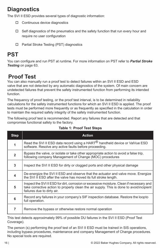
Proof TestYou can also manually run a proof test to detect failures within an SVI II ESD and ESD valve that are not detected by any automatic diagnostics of the system. Of main concern are undetected failures that prevent the safety instrumented function from performing its intended function.
The frequency of proof testing, or the proof test interval, is to be determined in reliability calculations for the safety instrumented functions for which an SVI II ESD is applied. The proof tests must be performed more frequently or as frequently as specified in the calculation in order to maintain the required safety integrity of the safety instrumented function.
The following proof test is recommended. Report any failures that are detected and that compromise functional safety to the factory.
This test detects approximately 99% of possible DU failures in the SVI II ESD (Proof Test Coverage).The person (s) performing the proof test of an SVI II ESD must be trained in SIS operations, including bypass procedures, maintenance and company Management of Change procedures. No special tools are required.
Table 1: Proof Test Steps
Step Action
1 Read the SVI II ESD data record using a HART® handheld device or ValVue ESD software. Resolve any active faults before proceeding.
2 Bypass the valve, or isolate or take other appropriate action to avoid a false trip, following company Management of Change (MOC) procedures
3 Inspect the SVI II ESD for dirty or clogged ports and other physical damage
4 De-energize the SVI II ESD and observe that the actuator and valve move. Energize the SVI II ESD after the valve has moved its full stroke length.
5Inspect the SVI II ESD for dirt, corrosion or excessive moisture. Clean if necessary and take corrective action to properly clean the air supply. This is done to avoid incipient failures due to dirty air.
6 Record any failures in your company’s SIF inspection database. Restore the loop to full operation.
7 Remove the bypass or otherwise restore normal operation

© 2022 Baker Hughes Company. All rights reserved. Masoneilan SVI II ESD Controller Quick Start Guide | 17
Installation and MaintenanceIntroductionThe SVI II ESD (Emergency Shutdown Device) is our solution to improve process integrity in a processing plant; designed to prevent and mitigate possibly uncontrollable situations.
The SVI II ESD is a PST controller that mounts on a pneumatically actuated valve assembly. Its role is to position an emergency shutdown valve to 0% or 100% with a probability of failure on demand (PFD) in accordance with IEC61508 for SIL3 application (SIL = Safety Integrity Level). It replaces the solenoid that is typically utilized to actuate a spring-return, while providing extensive online valve diagnostics.
Figure 1 - SVI II ESD Positioner
Using the Quick Start GuideThe SVI II ESD Quick Start Guide is intended to help an experienced Field Engineer install, setup, and calibrate an SVI II ESD in the most efficient manner possible. This document provides basic installation and setup instructions and is not intended to replace the in-depth information contained in the SVI II ESD Instruction Manual. If you experience problems that are not documented in this guide refer to the Masoneilan SVI II ESD Instruction Manual SIL3, or call your local representative. Sales offices are listed on the last page of this document.
18 | © 2022 Baker Hughes Company. All rights reserved.
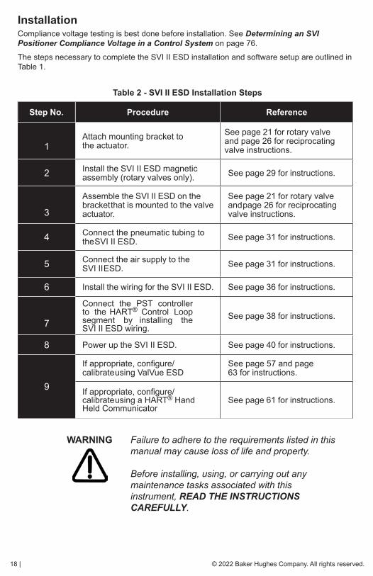
InstallationCompliance voltage testing is best done before installation. See Determining an SVI Positioner Compliance Voltage in a Control System on page 76.
The steps necessary to complete the SVI II ESD installation and software setup are outlined in Table 1.
Table 2 - SVI II ESD Installation Steps
Step No. Procedure Reference
1Attach mounting bracket to the actuator.
See page 21 for rotary valve and page 26 for reciprocating valve instructions.
2 Install the SVI II ESD magnetic assembly (rotary valves only). See page 29 for instructions.
3
Assemble the SVI II ESD on the bracket that is mounted to the valve actuator.
See page 21 for rotary valve and page 26 for reciprocating valve instructions.
4 Connect the pneumatic tubing to the SVI II ESD. See page 31 for instructions.
5 Connect the air supply to the SVI II ESD. See page 31 for instructions.
6 Install the wiring for the SVI II ESD. See page 36 for instructions.
7
Connect the PST controller to the HART® Control Loop segment by installing the SVI II ESD wiring.
See page 38 for instructions.
8 Power up the SVI II ESD. See page 40 for instructions.
9
If appropriate, configure/calibrate using ValVue ESD
See page 57 and page 63 for instructions.
If appropriate, configure/calibrate using a HART® Hand Held Communicator
See page 61 for instructions.
WARNING Failure to adhere to the requirements listed in this manual may cause loss of life and property. Before installing, using, or carrying out any maintenance tasks associated with this instrument, READ THE INSTRUCTIONS CAREFULLY.

© 2022 Baker Hughes Company. All rights reserved. Masoneilan SVI II ESD Controller Quick Start Guide | 19
Physical Location and Placement GuidelinesWhen determining the location of the SVI II ESD adhere to the following guidelines:
� The SVI II ESD must be accessible with sufficient room for cabling and pneumatic connections and must allow manual proof testing.
� Pneumatic piping to the actuator must be kept as short and straight as possible to minimize the airflow restrictions and potential clogging of the line. Long or kinked pneumatic tubes may also increase the valve closure time.
� The Breather/Vent port must be accessible and must be inspected for obstruction during manual proof testing.
� The SVI II ESD must be mounted in a mild vibration environment (see specifications at the end of this document). If excessive vibration can be expected special precautions must be taken to ensure the integrity of electrical and pneumatic connectors or reduce the vibration using appropriate damping mounts.
Necessary PrecautionsTo avoid injury or affecting the process when installing or replacing a PST controller on a control valve, ensure that:
� If the valve is located in a hazardous area make sure the area has been certified as safe or that all electrical power to the area has been disconnected before removing any covers or disconnecting any leads.
� Shut off air supply to the actuator and to any valve mounted equipment.
� Ensure the valve is isolated from the process by either shutting off the process or using bypass valves for isolation. Tag shutoff or bypass valves to guard against a turn-on while work is in progress.
� Bleed air from actuator and check that valve is in its de-energized position. It is now safe to disconnect and remove any valve mounted equipment that is being replaced.

20 | © 2022 Baker Hughes Company. All rights reserved.
SVI II ESD Components
Figure 2 provides a drawing of the SVI II ESD components.
Figure 2 - SVI II ESD Components
SVI II ESD Cover SVI II ESD Assembled
Pneumatic Train and Cover (I/P Module, Relay)
I/P Manifold
Electronics Module
Pneumatic Relay

© 2022 Baker Hughes Company. All rights reserved. Masoneilan SVI II ESD Controller Quick Start Guide | 21
Mounting the SVI II ESD on Rotary ValvesThis section describes the procedure for mounting the SVI II ESD on rotary control valves that have less than 60° rotation, such as a Masoneilan Camflex™. Figure 3 shows a side view of a Camflex actuator and the SVI II ESD actuator mounting brackets.
Figure 3 - Camflex with Mounting Bracket (side view)
Mounting the SVI II ESD on a Rotary ActuatorTools required:
� 3⁄16” Hex Key
� 5⁄32” Hex Key
� 3 mm, 4 mm, 5 mm Hex Key
� 7⁄16” Wrench
To mount the SVI II ESD:
1. Attach the SVI II ESD rotary mounting bracket to the valve actuator using two (2) 5⁄16 - 18 UNC flat-head cap screws. In the preferred mounting position, the long end of the mounting bracket is on your left when facing the actuator, for any position of the valve and actuator.
2. Bolt the extension shaft to the valve position take-off shaft using a 1⁄4 - 28 UNF socket flathead screw. Secure the machine screw holding the extension shaft with a torque of 144 in-lbs (16.269 N-m).
22 | © 2022 Baker Hughes Company. All rights reserved.
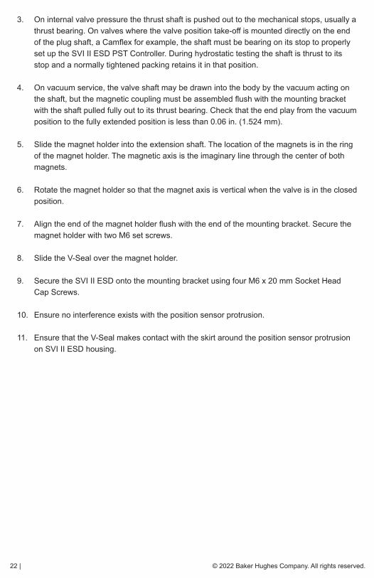
3. On internal valve pressure the thrust shaft is pushed out to the mechanical stops, usually a thrust bearing. On valves where the valve position take-off is mounted directly on the end of the plug shaft, a Camflex for example, the shaft must be bearing on its stop to properly set up the SVI II ESD PST Controller. During hydrostatic testing the shaft is thrust to its stop and a normally tightened packing retains it in that position.
4. On vacuum service, the valve shaft may be drawn into the body by the vacuum acting on the shaft, but the magnetic coupling must be assembled flush with the mounting bracket with the shaft pulled fully out to its thrust bearing. Check that the end play from the vacuum position to the fully extended position is less than 0.06 in. (1.524 mm).
5. Slide the magnet holder into the extension shaft. The location of the magnets is in the ring of the magnet holder. The magnetic axis is the imaginary line through the center of both magnets.
6. Rotate the magnet holder so that the magnet axis is vertical when the valve is in the closed position.
7. Align the end of the magnet holder flush with the end of the mounting bracket. Secure the magnet holder with two M6 set screws.
8. Slide the V-Seal over the magnet holder.
9. Secure the SVI II ESD onto the mounting bracket using four M6 x 20 mm Socket Head Cap Screws.
10. Ensure no interference exists with the position sensor protrusion.
11. Ensure that the V-Seal makes contact with the skirt around the position sensor protrusion on SVI II ESD housing.
© 2022 Baker Hughes Company. All rights reserved. Masoneilan SVI II ESD Controller Quick Start Guide | 23
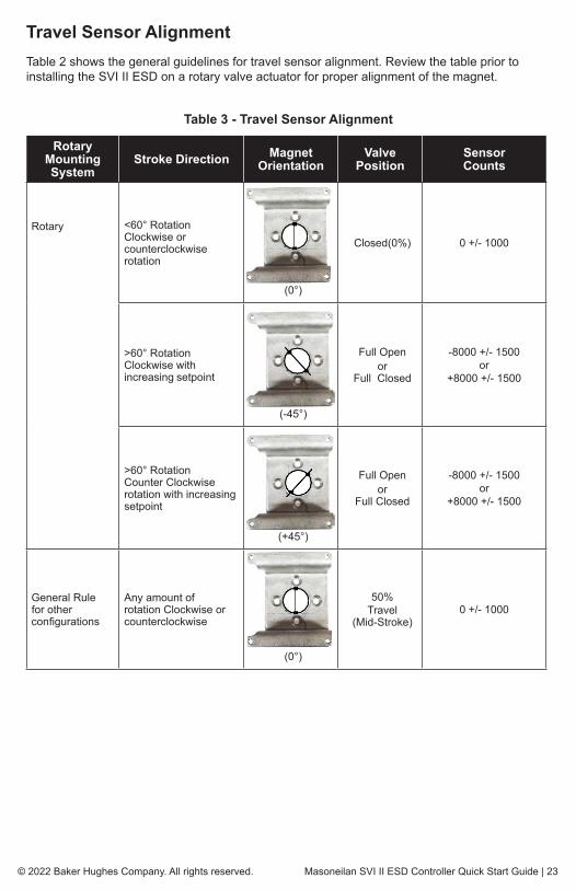
Travel Sensor AlignmentTable 2 shows the general guidelines for travel sensor alignment. Review the table prior to installing the SVI II ESD on a rotary valve actuator for proper alignment of the magnet.
Table 3 - Travel Sensor Alignment
Rotary Mounting System
Stroke Direction Magnet Orientation
Valve Position
Sensor Counts
Rotary <60° RotationClockwise or counterclockwise rotation
(0°)
Closed (0%) 0 +/- 1000
>60° RotationClockwise with increasing setpoint
(-45°)
Full Open or
Full Closed
-8000 +/- 1500or
+8000 +/- 1500
>60° RotationCounter Clockwise rotation with increasing setpoint
(+45°)
Full Open or
Full Closed
-8000 +/- 1500or
+8000 +/- 1500
General Rule for other con figurations
Any amount of rotation Clockwise or counterclockwise
(0°)
50%Travel
(Mid-Stroke)0 +/- 1000

24 | © 2022 Baker Hughes Company. All rights reserved.
Dismantling the SVI II ESD from Rotary Valves
WARNING Before carrying out any work on the device, power off the instrument or ensure that the device’s location conditions for potentially explosive atmosphere permit the safe opening of the cover.
To remove the SVI II ESD PST Controller from a rotary valve perform Steps 1 - 9 on page 24 in reverse.
Mounting the SVI II ESD with NAMUR KitsThere are two versions of this kit:
� 20 and 30 mm
� 50 mm
20 and 30 mm MountingTools required:
� 3 mm hex key
� 4 mm hex key Refer to Figure 4 for this procedure.
To mount using this kit:
1. Attach the mounting bracket to the valve actuator using four (4) M5 x 0.8 x 10 flat-head cap screws.
Figure 4 - Namur 20/30mm Mounting Kit
Quarter Turn Mount Plate
Mounting Bracket
Indicator Disc Bracket

© 2022 Baker Hughes Company. All rights reserved. Masoneilan SVI II ESD Controller Quick Start Guide | 25
2. Place the indicator disk with metal insert over the valve actuator shaft and secure using an M6 x 1.0 x 45 socket-head screw.
3. Place the Quarter Turn Mounting Plate into place sliding it through the anti-backlash spring into the dowel pin at the end of the plate into the hex head screw installed in step 2.
4. Secure the plate to the bracket using four (4) flat head cap screws.
50 mm MountingTools required:
� 3 mm hex key
� 4 mm hex key Refer to Figure 5 for this procedure.
To mount using this kit:
1. Attach the mounting bracket to the valve actuator using four (4) M5 x 0.8 x 10 flat-head cap screws.
2. Place the indicator disk with metal insert over the valve actuator shaft.
Figure 5 - Namur 50mm Mounting Kit
3. Place the Namur coupling and lever on top of the indicator disc and secure with an M6 x 1.0 x 25 socket-head screw.
4. Place the Quarter Turn Mounting Plate into place sliding it over the lever and through the anti-backlash spring.
5. Secure the bracket using four (4) flat head cap screws.
Quarter Turn Mount Plate
Mounting Bracket
Indicator Disc Bracket
Namur coupling w/lever
Anti-backlash spring
26 | © 2022 Baker Hughes Company. All rights reserved.
Mounting the SVI II ESD on Reciprocating ValvesThe process of mounting the SVI II ESD on a reciprocating valve consists of mounting the unit on the actuator that is attached to the valve. This section describes the procedure for mounting the SVI II ESD on Reciprocating Valves (using Masoneilan’s 87⁄88 Multi-Spring actuators as an example).
Mounting the SVI II ESD on a Reciprocating ActuatorTools required:
� 7⁄16” Combination Wrench (2 required)
� 3⁄8” Combination Wrench
� 1⁄2” Combination Wrench
� Phillips Head Screw Driver
� 5 mm Hex Key Wrench
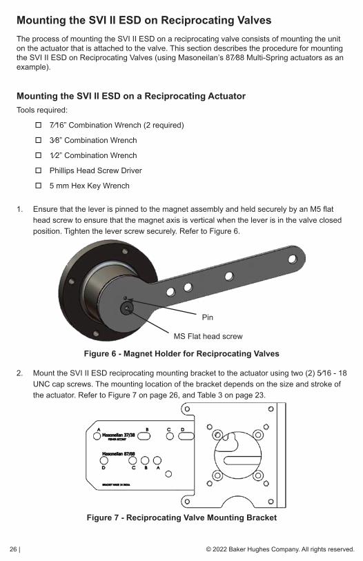
1. Ensure that the lever is pinned to the magnet assembly and held securely by an M5 flat head screw to ensure that the magnet axis is vertical when the lever is in the valve closed position. Tighten the lever screw securely. Refer to Figure 6.
Figure 6 - Magnet Holder for Reciprocating Valves
2. Mount the SVI II ESD reciprocating mounting bracket to the actuator using two (2) 5⁄16 - 18 UNC cap screws. The mounting location of the bracket depends on the size and stroke of the actuator. Refer to Figure 7 on page 26, and Table 3 on page 23.
Figure 7 - Reciprocating Valve Mounting Bracket
Pin
MS Flat head screw

© 2022 Baker Hughes Company. All rights reserved. Masoneilan SVI II ESD Controller Quick Start Guide | 27
3. Select mounting hole A, B, C or D for the stroke of the valve. For example, hole B is shown in Figure 9 on page 28 for a size 10 actuator with 1.0” stroke. Unless otherwise specified, the SVI II ESD mounting assumes that the actuator is in the normal upright position. The mounting hole in the slotted opening of the mounting bracket must be left when facing the actuator, with the actuator in the upright position.
4. Thread the take-off rod to the actuator stem connector. Refer to Figure 8. Ensure that the travel pointer located on the coupling is correctly positioned.
5. Attach the right hand threaded rod end to the SVI II ESD lever using a 1⁄4 - 20 x 1” cap screw and nut as shown. The lever hole position to be used depends upon the specific valve stroke. Refer to Figure 9 on page 28 and the Reciprocating Valve Linkage Selection, Table 3 on page 23.
6. Thread the right hand lock nut and turnbuckle onto the right hand rod end approximately two turns. Turnbuckle length is a function of actuator size. (Refer to Table 3.).
7. Secure the magnet housing assembly, including the lever and right hand rod end, to the bracket using four M5 X 10 mm flat head screws.
8. Attach the left hand threaded rod end to the take-off rod with 1⁄4 - 20 UNC nut and thread the left hand lock nut onto the rod end.
Figure 8 - Reciprocating Linkage
9. Move the valve to its closed position. For air to extend, this requires using air pressure in the actuator to fully stroke the actuator. For air to retract, actuators vent the actuator of air pressure.
10. Thread the turnbuckle onto the left hand threaded rod end. Refer to Figure 8.
11. Adjust the turnbuckle until the hole in the SVI II ESD lever is aligned with the indicating hole in the bracket. Tighten both turnbuckle lock nuts. Refer to Figure 7.
28 | © 2022 Baker Hughes Company. All rights reserved.
Mounting the SVI II ESD on a Reciprocating Actuator (cont.)
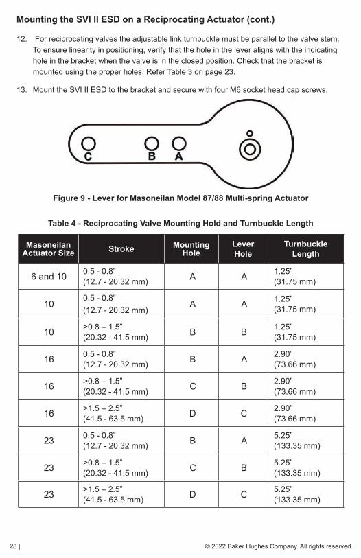
12. For reciprocating valves the adjustable link turnbuckle must be parallel to the valve stem. To ensure linearity in positioning, verify that the hole in the lever aligns with the indicating hole in the bracket when the valve is in the closed position. Check that the bracket is mounted using the proper holes. Refer Table 3 on page 23.
13. Mount the SVI II ESD to the bracket and secure with four M6 socket head cap screws.
Figure 9 - Lever for Masoneilan Model 87/88 Multi-spring Actuator
Table 4 - Reciprocating Valve Mounting Hold and Turnbuckle Length
Masoneilan Actuator Size Stroke Mounting
HoleLever Hole
Turnbuckle Length
6 and 10 0.5 - 0.8”(12.7 - 20.32 mm) A A 1.25”
(31.75 mm)
100.5 - 0.8”(12.7 - 20.32 mm)
A A 1.25”(31.75 mm)
10 >0.8 – 1.5”(20.32 - 41.5 mm) B B 1.25”
(31.75 mm)
16 0.5 - 0.8”(12.7 - 20.32 mm) B A 2.90”
(73.66 mm)
16 >0.8 – 1.5”(20.32 - 41.5 mm) C B 2.90”
(73.66 mm)
16 >1.5 – 2.5”(41.5 - 63.5 mm) D C 2.90”
(73.66 mm)
23 0.5 - 0.8”(12.7 - 20.32 mm) B A 5.25”
(133.35 mm)
23 >0.8 – 1.5”(20.32 - 41.5 mm) C B 5.25”
(133.35 mm)
23 >1.5 – 2.5”(41.5 - 63.5 mm) D C 5.25”
(133.35 mm)
© 2022 Baker Hughes Company. All rights reserved. Masoneilan SVI II ESD Controller Quick Start Guide | 29
Dismantling the SVI II ESD from Reciprocating Valves
WARNING Before carrying out any work on the device, power off the instrument or ensure that the local conditions for potentially explosive atmosphere permit the safe opening of the cover.
To remove the SVI II ESD PST Controller from a reciprocating valve perform Steps 1 - 12 on page 26 in the reverse order.
Checking the MagnetThere are two methods of checking the SVI II ESD magnet:
� Perform a visual inspection
� Use ValVue ESD to check the magnet
Performing a Visual InspectionTo perform a visual inspection refer to Table 2 on page 18 and ensure that the magnet is correctly oriented for the actuator/valve configuration.
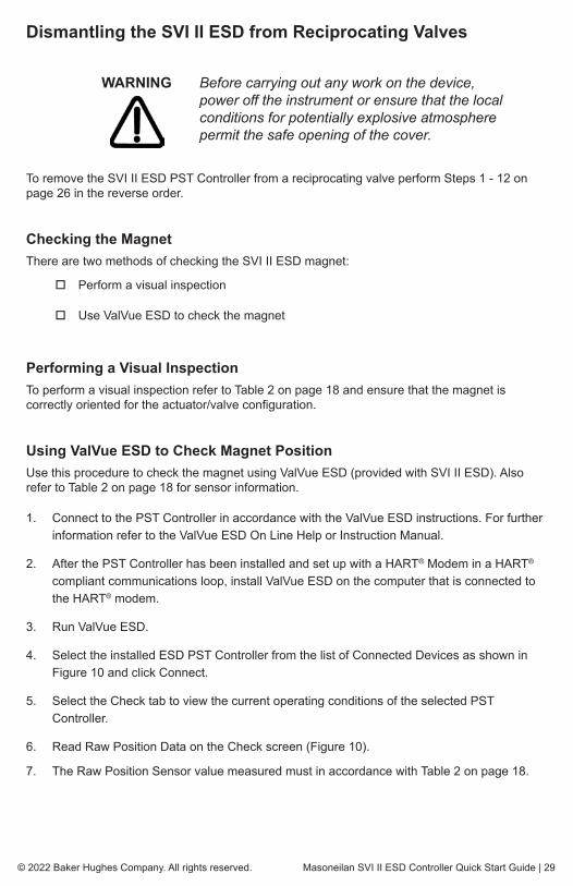
Using ValVue ESD to Check Magnet PositionUse this procedure to check the magnet using ValVue ESD (provided with SVI II ESD). Also refer to Table 2 on page 18 for sensor information.
1. Connect to the PST Controller in accordance with the ValVue ESD instructions. For further information refer to the ValVue ESD On Line Help or Instruction Manual.
2. After the PST Controller has been installed and set up with a HART® Modem in a HART® compliant communications loop, install ValVue ESD on the computer that is connected to the HART® modem.
3. Run ValVue ESD.
4. Select the installed ESD PST Controller from the list of Connected Devices as shown in Figure 10 and click Connect.
5. Select the Check tab to view the current operating conditions of the selected PST Controller.
6. Read Raw Position Data on the Check screen (Figure 10).
7. The Raw Position Sensor value measured must in accordance with Table 2 on page 18.

30 | © 2022 Baker Hughes Company. All rights reserved.
ValVue ESD Connected Devices Screen
Figure 10 - ValVue ESD for Checking Magnet Position
Checking Actuator, Linkages, or Rotary AdapterVerify that the mounting has not been damaged in shipment for a pre-mounted SVI II ESD, physically inspect the actuator, linkage. Record the following information for the configuration checkout:
� Valve Air to Open (ATO) or Air to Close (ATC)
� Actuator pressure rating
� Actuator bench range
� Inherent trim characteristic of the control valve; linear, equal percentage, or other.
NOTE For the aforementioned information, refer to the valve data sheet or model number of control valve.
Verify Mounting and Linkage AdjustmentInspect the mounting and make any needed adjustments before running the PST Controller and checking the digital configuration.
ValVue ESD Check Screen

© 2022 Baker Hughes Company. All rights reserved. Masoneilan SVI II ESD Controller Quick Start Guide | 31
Connecting the Tubing and Air Supply
NOTE When an SVI II ESD is turned on it is advisable to apply the air supply before applying the electrical input signal.
NOTE For small actuators it may be necessary to use 1/8” tubing for Autotune to work properly.
This section describes the process for connecting the tubing and air supply to a PST Controller.
Pneumatic ConnectionsThe SVI II ESD is intended for use with industrial compressed air or natural gas systems only that meets the requirements of ISA standard 7.3. Supply pressure must not exceed 120 psi. A coalescing filter can be used to assure that the supply air is sufficiently free of oil, water, and particulate contaminants. Ensure that an adequate pressure relief provision is installed when the application of system supply pressure could cause peripheral equipment to malfunction. Installation must be in accordance with local and national compressed air and instrumentation codes. Table 4 provides the pneumatic connections and air supply requirements for the SVI II ESD.
Table 5 - Pneumatic Connections and Air Supply Requirements
Recommended Piping Inlet/Outlet
1/2” stainless steel or PVC tubing. The length of tubing between the SVI II ESD and the valve must be kept as short as possible and free of kinks
Instrument Air Pressure 30 - 120 psi (2.07 - 8.27 bar) (207 - 827 kPa)
Dew Point At least 18°F (10°C) below minimum anticipated ambient temperature
Particulate Matter Filtered to 5 microns
Oil Content Less than 1 ppm w/w
Contaminants Free of all corrosive contaminants

32 | © 2022 Baker Hughes Company. All rights reserved.
Natural Gas Supply ConsiderationsIf the pneumatic system is connected to natural gas, the pneumatic control system constantly bleeds a small amount of the natural gas into the area around the SVI II ESD. Also, during a vent cycle (actuator pressure relief), natural gas from the actuator is released into the area around the SVI vent port. Consider both sources of natural gas when evaluating the Hazardous Classification for the area (See the Masoneilan SVI II ESD Smart Valve Interface with SIL3 Emergency Shutdown PST Controller Installation and Maintenance Manual for further discussion on installing an SVI II ESD in a natural gas environment).
Remote piping of the actuator venting is possible to reduce the amount of natural gas released into the area around the SVI II ESD (See BHMN-SVI-ESD-18946 Masoneilan SVI II ESD Smart Valve Interface with SIL3 Emergency Shutdown PST Controller Installation and Maintenance Manual for further discussion on installing an SVI II ESD in a natural gas environment). Installing remote actuator vent gas piping does not capture all gas emitted. A small amount of natural gas still bleeds constantly in the area around the SVI II ESD. Consider the bleeding and releasing of natural gas when evaluating the Hazardous Clarification for the area.
NOTE Area classification is the responsibility of the end user.
The interior of the SVI II ESD is positively pressurized with supply medium. Appropriate safety measures must be taken to handle pressurized natural gas that may enter the electrical conduit or cable system.
WARNING Do not remove the instrument cover or connect to an electrical circuit unless the power is disconnected. Natural gas will escape into the surrounding atmosphere upon disconnecting any of the pneumatic connections or removing any cover or pressure containing component.
WARNING EXPLOSION HAZARD - Do not disconnect equipment or remove cover unless power has been de-energized or the area is know to be non-hazardous.
Natural gas may be contained within the SVI II ESD. Even after disconnecting the SVI II ESD from all the pneumatic connections Natural Gas may still be present within the SVI II ESD.
WARNING EXPLOSION HAZARD - Natural gas may escape from the SVI II ESD upon removal of any cover or component.
Ensure the cover is correctly installed before putting this unit into service.

© 2022 Baker Hughes Company. All rights reserved. Masoneilan SVI II ESD Controller Quick Start Guide | 33
WARNING EXPLOSION HAZARD - An improperly installed cover could leak natural gas into the area.
The interior of the SVI II ESD is positively pressure with supply medium. Appropriate safety measures must be taken to handle pressurized natural gas that may enter the electrical conduit or cable system.
WARNING EXPLOSION HAZARD - A missing or improperly installed conduit seal, cable seal, or cable gland could leak natural gas into the conduit/cable system, and/or into any area where the conduit/ cabling system is present or connected to.
WARNING Natural gas will constantly bleed and possibly vent from the SVI II ESD if connected to a natural gas supply. Hazardous area clarification is the responsibility of the end user. Area ventilation and other safety measures may be required to maintain a safe environment.
WARNING Installation in poorly ventilated confined areas, with any potential of gases other than oxygen being present, can lead to a risk of personnel asphyxiation.
WARNING Isolate the valve from the process and disconnect air tubing from the positioner. Disconnect air fully to avoid injury or process damage.
34 | © 2022 Baker Hughes Company. All rights reserved.
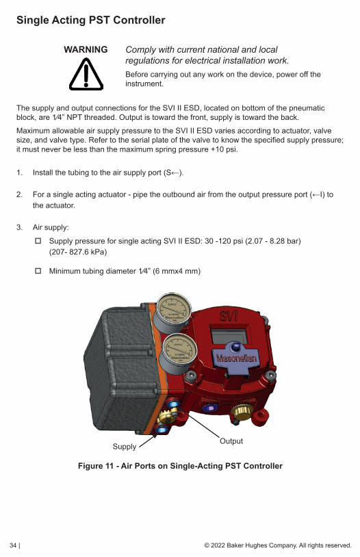
Single Acting PST Controller
WARNING Comply with current national and local regulations for electrical installation work.
Before carrying out any work on the device, power off the instrument.
The supply and output connections for the SVI II ESD, located on bottom of the pneumatic block, are 1⁄4” NPT threaded. Output is toward the front, supply is toward the back.
Maximum allowable air supply pressure to the SVI II ESD varies according to actuator, valve size, and valve type. Refer to the serial plate of the valve to know the specified supply pressure; it must never be less than the maximum spring pressure +10 psi.
1. Install the tubing to the air supply port (S←).
2. For a single acting actuator - pipe the outbound air from the output pressure port (←I) to the actuator.
3. Air supply:
� Supply pressure for single acting SVI II ESD: 30 -120 psi (2.07 - 8.28 bar) (207- 827.6 kPa)
� Minimum tubing diameter 1⁄4” (6 mmx4 mm)
Figure 11 - Air Ports on Single-Acting PST Controller
SupplyOutput

© 2022 Baker Hughes Company. All rights reserved. Masoneilan SVI II ESD Controller Quick Start Guide | 35
Checking the Air SupplyAfter the tubing is installed, use the following procedure to connect the air supply.
1. Supply clean, dry compressed air to the filter regulator.
2. Turn on the air supply.
3. Adjust the filter regulator.
4. Supply pressure must be 10 psi greater than the spring range of the actuator but may not exceed the rated actuator pressure. Refer to the valve or actuator instruction manual.
5. Inspect the tubing connections between the filter-regulator and the positioner for leaks.
6. Verify that the tubing is not bent or crushed.
7. Verify that all fittings are leak tight.
NOTE Do not use Teflon pipe seal tape. The Teflon tape can shred into particles that are harmful to the pneumatic components.
For detailed information on pneumatic connections refer to Pneumatic Connections on page 31.

36 | © 2022 Baker Hughes Company. All rights reserved.
Wiring the SVI II ESDThere are two components to wiring the SVI II ESD; making an electrical connection for power and making a local control loop connection for HART® communication.
Electrical Connection GuidelinesWhen making the SVI II ESD electrical connections, follow these guidelines:1. The SVI II ESD device is available in two control signal configurations: 20 mA or 24 VDC.
2. Provide sufficient electrical isolation between adjacent signal lines and between signal lines and ground for all wiring.
3. Use stranded 14 to 22 AWG (or equivalent gauge and flexibility).
4. Use conduit sealant to prevent condensation from entering the enclosure and, in Class 1 Div. 2 conditions to prevent hazardous gases and vapors from migrating through the conduit to the control room or an open ignition source.
5. Wire according to the National Electrical Code (ANSI-NFPA 70) or other applicable local codes.
6. The terminal clamps are designed for one wire only; DO NOT attempt to terminate multiple wires into one terminal.
7. Strip the wires to the recommended length (See product specifications).
8. Ensure all wire stands are fully inserted into the terminal block and no shorts between adjacent wires on the terminal block are possible.
9. Use care when running signal wiring near to or crossing conduit or wiring that supplies power to motors, solenoids, lighting, horns, bells, etc. Provide sufficient electrical isolation and shielding against electro-magnetic interference from items in the vicinity of the cable run.
10. Run AC power wiring in a separate conduit from DC power. All power wiring to and from the SVI II ESD must be in grounded conduit. Protect outdoor cable runs against lightning strike.
11. Connect the SVI II ESD to a high quality instrument grade ground sized as required by local electrical codes. A grounding stud is provided inside the enclosure.
WARNING Comply with current national and local regulations for electrical installation work.
Comply with national and local explosive atmosphere regulations.
Before carrying out any work on the device, power off the instrument or make sure that the locale conditions for potentially explosive atmosphere permit the safe opening of the cover.
CAUTION Refer to Optional Switch Load Limits on page 72 for guidelines on safely wiring switch load limits.

© 2022 Baker Hughes Company. All rights reserved. Masoneilan SVI II ESD Controller Quick Start Guide | 37
SVI II ESD ConfigurationsThere are three possible SVI II ESD installation configurations each with a different wiring scheme.
� Analog Safety Demand (ASD)
� Discrete Safety Demand (DSD)
� Analog with Discrete Safety Demand (A/DSD)
Analog Safety Demand (ASD)The Analog Safety Demand configuration is: 4 - 20 mA signal, power and trip signal with super- imposed HART® communications (Figure 12).
Figure 12 - Analog Safety Demand (ASD) Configuration
Discrete Safety Demand (DSD)The Discrete Safety Demand configuration is: 24 VDC, power and trip signal with superimposed HART® communications (Figure 13).
Figure 13 - Discrete Safety Demand (DSD) Configuration

38 | © 2022 Baker Hughes Company. All rights reserved.
Analog with Discrete Safety Demand (A/DSD)The Analog with Discrete Demand configuration is: 4 - 20 mA power input with superimposed HART® communications for control system and 24 VDC 2 wire for Safety System (Figure 14).
Figure 14 - Analog with Discrete Safety Demand (A/DSD) Configuration
HART® Wiring GuidelinesIn order for the SVI II ESD to communicate, the SVI II ESD must be physically connected to a HART® compliant network. “Connecting to the Control Loop” outlines wiring the SVI II ESD.
Connecting to the Control LoopThe SVI II ESD positioner MUST BE grounded according to local regulations. It is important to maintain correct polarity at all times, otherwise the positioner may not operate properly. Physically connect the SVI II ESD to the HART® loop using a cable specified by Field Comm®. A shielded cable is recommended.
To connect the Control Loop to the SVI II ESD:
1. Connect one end of the cable to the control loop’s 4 - 20 mA output.
2. Remove the threaded wiring covers on the positioner.
3. Connect the other end of the cable to the SVI II ESD. There are two threaded openings on the positioner. Use the opening with the red plastic insert.
4. Maintain polarity + and - respectively.

© 2022 Baker Hughes Company. All rights reserved. Masoneilan SVI II ESD Controller Quick Start Guide | 39
Wiring a Position Retransmit
CAUTION For proper operation, maintain signal polarity + and - respectively.
To connect:
1. Strip the insulation at the end of the wires. Strip approximately 1/4” (6.35 mm) of the insulation at the end of wires (wire size 14 to 28 AWG, 2.5 mm2 to .08 mm2).
2. Connect the +⁄- terminals from the 4-20 mA Out to the position retransmit input signal: + to + and - to -. See Figure 15 on page 44.
To troubleshoot retransmit connections:
� Ensure that the retransmit circuit has a minimum voltage of 10 V (maximum 30 V).
3. Ensure the minimum AO current is 3.2 mA. If the module loses power and the AO circuit remains powered, the AO signal will be 3.2 mA.
Compliance Voltage in Single Drop Current ModeThe SVI II ESD requires 9.6 Volts at 20 mA and 11.0 Volts at 4 mA. Typical HART® devices require MORE Voltage at higher current and MORE current source have LESS Voltage available at higher current. The SVI II ESD is unique in that it requires LESS Voltage at higher current which compliments the characteristic of the source requiring only 9.6 Volts at 20 mA. See Determining an SVI Positioner Compliance Voltage in a Control System on page 76.
NOTE Improperly or inadequately grounded installations can cause noise or instability in the control loop. The internal electronic components are isolated from ground. Grounding the case is unnecessary for functional purposes but grounding the case may be necessary to conform to local codes.

40 | © 2022 Baker Hughes Company. All rights reserved.
Powering Up the SVI II ESDVerify the wiring and connections and then connect the current source.
Connecting a Power SourceDepending upon the configuration of the SVI II ESD, powering up the unit consists of connecting to the 4-20 mA current source or the 24 VDC power source.
WARNING This process can cause the valve to move. Before proceeding ensure the valve is isolated from the process. Keep hands clear from moving parts.
NOTE When an SVI II ESD is turned on it is advisable to apply the air supply before applying the electrical input signal.
Powering Up the ASD ConfigurationThe ASD, or Analog Safety Demand, configuration uses a 4 - 20mA current source for power.
CAUTION Use of a low impedance voltage source damages the SVI II ESD. The current source must be a true high impedance current limiting device. A proper current source explicitly enables adjustment of the current in mA, not Volts.
To power up the ASD configuration of the SVI II ESD:
1. Loosen the four (4) cover screws and remove the cover of the SVI II ESD.
2. Connect the +⁄- terminals of the current source to the 4 - 20mA IN connector (on the terminal board). The current source + must connect to the terminal board connector +, and the same for -. See Figure 15 on page 44.
3. Reinstall the cover and display.
4. Adjust current to 20 mA. On initial power up of a newly installed SVI II ESD, the positioner starts up in SETUP mode using the default factory-installed instrument parameters. Once calibrated and configured and set to NORMAL, the positioner cycles through the NORMAL cycle menu and the following values appear:
� PRES: Pressure - unit of measurement and value
� SIGNAL
� POS (Position) An exclamation point (!) appears in the display’s top left corner to indicate that further instrument status is available.
5. Proceed to Configuration on Configuration on page 56 and Calibration on page 60.

© 2022 Baker Hughes Company. All rights reserved. Masoneilan SVI II ESD Controller Quick Start Guide | 41
Powering Up the DSD ConfigurationThe DSD, or Discrete Safety Demand, configuration uses a 24 VDC power source. To power up the DSD configuration of the SVI II ESD:
1. Loosen the four (4) cover screws and remove the cover of the SVI II ESD.
2. Connect the +⁄- terminals of the 24 VDC power source to the 24 VDC ESD IN connector (on the terminal board). The voltage + must connect to the terminal board connector +, and the same for -. See Figure 16 on page 44.
3. Reinstall the cover and display.
4. Turn on the voltage source. On initial power up, of a newly installed SVI II ESD, the positioner runs in SETUP mode using the default instrument parameters installed at the factory. Once calibrated and configured and set to NORMAL, the positioner cycles through the NORMAL cycle menu and the following values appear:
� PRES: Pressure - unit of measurement and value
� SIGNAL
� POS (Position) An exclamation point (!) appears in the display’s top left corner to indicate that further instrument status is available.
5. Proceed to Configuration” on page 56 and Calibration on page 60.
Powering Up the A/DSD ConfigurationThe A/DSD, or Analog/Discrete Safety Demand, configuration uses both a 4 - 20 mA current source (for the unit) and a 24 VDC source (for the safety trip) for power.
CAUTION Use of a low impedance voltage source damages the SVI II ESD. The current source must be a true high impedance current limiting device. A proper current source explicitly enables adjustment of the current in mA, not Volts.
To power up the SVI II ESD:
1. Loosen the four (4) cover screws and remove the cover of the SVI II ESD.
2. Connect the +⁄- terminals of the current source to the 4 - 20mA IN connector (on the terminal board). The current source + must connect to the terminal board connector +, and the same for -. See Figure 14 on page 38.
3. Reinstall the cover and display.
4. Adjust the current to 20 mA.
5. Connect the +⁄- terminals of the 24 VDC power source to the 24 VDC ESD IN connector (on the terminal board). The voltage source + must connect to the terminal board connector +, and the same for -. Figure 17 on page 45.
6. Reinstall the cover and display.

42 | © 2022 Baker Hughes Company. All rights reserved.
Powering Up the A/DSD Configuration (cont.)
7. Turn on the voltage source. On initial power up of a newly installed SVI II ESD, the positioner runs in SETUP mode using the default factory-installed instrument parameters. Once calibrated and configured and set to NORMAL, the positioner cycles through the NORMAL cycle menu and the following values appear:
� PRES: Pressure - unit of measurement and value
� SIGNAL
� POS (Position) An exclamation point (!) appears in the display’s top left corner to indicate that further instrument status is available.
8. Proceed to Configuration on page 56 and Calibration on page 60.
NOTE The safety function of the SIF (shutdown of the valve on demand) must be tested after installation.

© 2022 Baker Hughes Company. All rights reserved. Masoneilan SVI II ESD Controller Quick Start Guide | 43
Checking the Electronic Module Connections
WARNING Comply with current national and local regulations for electrical installation work.
Before carrying out any work on the device, power off the instrument.
All connections to electronic module in the SVI II ESD are made through the terminal board. There are three versions of the terminal board, dependent on the configuration you have; ASD, DSD, or A/DSD. The SVI II ESD terminal board has a terminal block with cage clamp connectors. Confirm that all applicable connections to the electronics module connectors are correct. Not all options are available for every model. Refer to Table 5 for available functionality.
Table 6 - SVI II ESD Models and Functionality
1. Latching is software configurable.
2. 1 - 5 VDC variable is sent using HART® command #3 as the variable TV.
I/O ON SVI II ESD
Usage
SVI II ESDASD Analog Safety
Demand
SVI II ESDDSD Discrete
Safety Demand
SVI II ESDA/DSD
Analog Power with Discrete Safety Demand
Analog In (4-20mA)Safety Trip Signal + HART + Analog PST
Not UsedDevice Power + Analog PST + HART
ESD In (0-24 VDC) Not UsedSafety Trip Signal + HART
Safety Trip Signal
SW1 (1A, 24 VDC) Not Configurable Not Configurable Not Configurable
SW2 (1A, 24 VDC) Configurable Status Configurable Status Configurable Status
DI (switch input) Unlatch(1) Unlatch(1) Unlatch(1)
PV (1-5 VDC)Read Tight Shutoff Flow(2)
Read Tight Shutoff Flow(2) Read Tight Shutoff Flow(2)
Local LCD / ButtonsESD Status Local PST
ESD Status Local PST
ESD Status Local PST

44 | © 2022 Baker Hughes Company. All rights reserved.
Checking the Electronic Module Connections (cont.)
Figure 15 - Connections to ASD Electronics Module (via Terminal Board)
Figure 16 - Connections to DSD Electronics Module (via Terminal Board)
Position RetransmitConfiguration Lock Jumper
Output Switch SW #1 Output Switch SW #2
Process Variable
4-20 mA Input Signal
Display
Position Retransmit
Process Variable
24 VDC IN Input Signal
Display
Output Switch SW #2Configuration Lock Jumper
Output Switch SW #1

© 2022 Baker Hughes Company. All rights reserved. Masoneilan SVI II ESD Controller Quick Start Guide | 45
Figure 17 - Connections to A/DSD Electronics Module (via Terminal Board)
Position RetransmitConfiguration Lock Jumper
Output Switch SW #1 Output Switch SW #2
Process Variable
4-20 mA Input Signal
Display
Digital Signal
24 VDC IN Input Signal
46 | © 2022 Baker Hughes Company. All rights reserved.
Making Connections to the Terminal BoardEach terminal block on the terminal board has a cage clamp connector. One side of the connector has the actual connection for the wire, with a lever at the top. If there is an option present that is not properly connected to the terminal board or if adding a new option, connect the wires from the option as follows:
1. If the option’s wires have not been stripped, strip the insulation at the end of wires.
2. Locate the correct terminal block on the terminal board (see Figure 15 on page 44).
3. Push the lever back at the top connector until you see the opening for wire insertion. The connectors are spring activated and may require a lot of pressure to move the lever.
4. Insert the wire into the opening and release the lever.
NOTE Improperly or inadequately grounded installations can cause noise or instability in the control loop. The internal electronic components are isolated from ground. Grounding the case is unnecessary for functional purposes but grounding the case may be necessary to conform to local codes. Side loading the cage clamp lever can cause damage.
NOTE Position Retransmit: when wiring this feature:
Wire using the same gauge wire as for the 4-20 mA control loop. In general, ensure that it is connected to the control system’s analog systems card. Ensure the control loop is powered when using a meter to make any measurements.

© 2022 Baker Hughes Company. All rights reserved. Masoneilan SVI II ESD Controller Quick Start Guide | 47
SVI II ESD MaintenanceRepair and ReplacementRepairs may be made only by authorized personnel trained to repair Safety Devices.
CAUTION When working on safety rated equipment appropriate risk reduction safety measures must be in place.
1. A conservative approach is taken in estimating the service interval for the digital valve controller in Safety Instrumented Systems. For SIS applications, perform preventive maintenance on the SVI II ESD after five years from the shipment date, if the average daily ambient temperature is below 60°C (140°F). Where ambient temperature exceeds 60°C (140°F) for extended periods, reduce this maintenance interval based on plant experience.
2. SVI II ESD preventive maintenance consists of replacing gaskets, O-rings in the device and a visual inspection of moving components to verify satisfactory condition. Following maintenance, the SVI II ESD must be reinstalled on the valve actuator and calibrated per the procedures in this Quick Start Guide or in the SVI II ESD Instruction Manual SIL3, BHMN-SVI-ESD-18946. After calibration, validate the SVI II ESD functional safety. All maintenance procedures must be performed only by authorized personnel trained to repair Safety Devices.
3. If alarms or alerts are detected during operation, maintenance or periodic inspection and test, immediately take corrective action according to the troubleshooting and repair procedures given in the Instruction Manual.
4. The tools required for repair of the SVI II ESD are also listed in the SVI II ESD Instruction Manual SIL3, BHMN-SVI-ESD-18946.
Factory NotificationReport any failures detected that compromise functional safety to the factory. Contact your local service representative. Sales Office locations are listed on the back cover of this document.
NOTE Baker Hughes does not assume responsibility for the selection, use, or maintenance of any product. Responsibility for proper selection, use of any Masoneilan products remain solely with the purchaser and end-user. The SVI II ESD requires recertification, which must be performed by authorized personnel trained to repair Safety Devices.
The contents of this publication are presented for informational purposes only, and while every effort has been made to ensure their accuracy, they are not to be construed as warranties or guarantees, express or implied, regarding the products or services described herein or their use or applicability. We reserve the right to modify or improve the designs or specifications of such products at any time without notice.
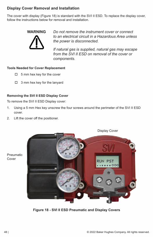
48 | © 2022 Baker Hughes Company. All rights reserved.
Display Cover Removal and Installation
The cover with display (Figure 18) is standard with the SVI II ESD. To replace the display cover, follow the instructions below for removal and installation.
WARNING Do not remove the instrument cover or connect to an electrical circuit in a Hazardous Area unless the power is disconnected.
If natural gas is supplied, natural gas may escape from the SVI II ESD on removal of the cover or components.
Tools Needed for Cover Replacement
� 5 mm hex key for the cover
� 3 mm hex key for the lanyard
Removing the SVI II ESD Display CoverTo remove the SVI II ESD Display cover:
1. Using a 5 mm Hex key unscrew the four screws around the perimeter of the SVI II ESD cover.
2. Lift the cover off the positioner.
Figure 18 - SVI II ESD Pneumatic and Display Covers
Display Cover
Pneumatic Cover

© 2022 Baker Hughes Company. All rights reserved. Masoneilan SVI II ESD Controller Quick Start Guide | 49
Installing the SVI II ESD Display CoverThe replacement Display Cover is shipped with a lanyard to prevent the cable (that connects from the display to the Terminal Board) from breaking. Insert the lanyard under the screw in the lower left corner that attaches the terminal board to the SVI II ESD housing.
To install the cover:
1. Install the lanyard and tighten the screw to 5 in/lb.
2. Using a 3 mm hex key, remove the screw from the lower left corner, connecting the terminal board to the SVI II ESD housing.
3. Connect the cable from the display into the LCD connector on the terminal board.
4. Ensure that the gasket is in its groove in the housing.
5. Place the cover over the screw mounts.
6. Tighten the four screws with the 5 mm hex key.
7. After installing the new display Powering Up the SVI II ESD on page 40.
NOTE The cover of the SVI II ESD is a critical component for safety in Hazardous Areas. To ensure safe operation the flat surfaces of the cover and the housing must be clean and absolutely free of particles or dents. There must be no gap between the housing and cover; torque spec is 50 in/lb.
Ensure that:
� The gasket is seated in the groove in the housing flange.
� No wires or retaining cable can be trapped under the cover flange.
� The flange area is not corroded and the surface is not scarred.
� The four cover bolts are securely tightened to 50 in/lb.
50 | © 2022 Baker Hughes Company. All rights reserved.
Setup, Calibration and PST
OverviewThis section provides information on SVI II ESD setup and calibration procedures to ensure proper valve positioning and Partial Stroke Testing (PST).
NOTE Perform the setup and calibration procedures in this section before putting the SVI II ESD into operation as the SIF.
SVI II ESD SetupThere are two SVI II ESD items to consider prior to actual setup and calibration:
1. SVI II ESD display and pushbuttons for accessing SVI II ESD menu functions.2. SVI II ESD modes of operation.
Pushbuttons and Local DisplayLocal interface to the SVI II ESD consists of the LCD alphanumeric display and pushbuttons. The SVI II ESD can be controlled locally through the device-mounted pushbuttons and digital display, shown in Figure 1 on page 17. Using the display you can read the input signal, valve position, and actuator pressure. The display sequences from one variable to the next is every 1.5 seconds.
Using the pushbuttons you can change operating modes at any time and step through a menu structure to perform a wide range of manual operation, calibration, configuration, and monitoring functions. The SVI II ESD provides internal diagnostics and if a fault is detected it appears on the display. ValVue ESD provides advanced diagnostic functions. The pushbuttons do not support ValVue ESD advanced diagnostics functions.
NOTE The positioner LCD may indicate Failsafe when an alarm condition exists. Use the pushbuttons to view and clear alarms. See Accessing Diagnostic Information in the Masoneilan SVI II ESD Smart Valve Interface with SIL3 Emergency Shutdown PST
Controller Installation and Maintenance Manual.

© 2022 Baker Hughes Company. All rights reserved. Masoneilan SVI II ESD Controller Quick Start Guide | 51
Table 7 lists each display menu and provides a functional description of the menu, including parameters, where applicable.
Table 7 - Pushbutton Display Menus
Pushbutton Menu Function/Parameters
NORMALRuns the SVI II ESD in normal operating mode, displays position, signal and pressure.
MANUAL
Executes manual mode in which the valve does not respond to input signal and you can adjust position manually. In MANUAL the valve responds to the Trip signal in addition to responding to HART. MANUAL menu provides access to SETUP.
SETUPProvides access to lower level setup menus; configuration (CONFIG), calibration (CALIB) and PST configuration.
CONFIGSets the following parameters: ATO/ATC, Pressure units, display language.
CALIBCalibrates the SVI II ESD by running the STOPS (find stops) andTUNE (autotune) functions.
PST CONF
Configures the following PST parameters: TRAVEL (range in a percentage of 100% travel over for partial stroke testing to occur), PMIN (minimum amount of pressure allowed during PST), MAX TIME (maximum amount of time in seconds allowed for partial stroke), RAMPSPEED.
VIEW DATA Displays the parameters set in CONFIG and PST CONF.
VIEW ERR Displays all current errors.
CLR ERR Clears current errors, one at a time.
RUN PST Executes PST (Partial Stroke Testing).

52 | © 2022 Baker Hughes Company. All rights reserved.
Accessing PushbuttonsThe local pushbuttons are located behind a hinged cover, directly below the display window. To open the cover loosen the screw and swing the cover down. Always re-fasten the cover after use to protect the pushbuttons from environmental contamination.
The three pushbuttons perform the following functions:
� Left Button - Marked *, permits you to select or accept the value or parameter option currently displayed.
� Middle Button - Marked –, permits you to move back through the menu structure to the previous item in the menu or decrement the value currently shown in the digital display. When used to decrease a displayed value, holding the button down causes the value to decrease at a faster rate.
� Right Button - Marked +, permits you to move forward through the menu structure to the next item in the menu, or to increment the value currently
� Shown in the digital display. When used to increase a displayed value, holding this button down causes the value to increase at a faster rate.
NOTE When an exclamation point (!) appears in the SVI II ESD display window, it indicates instrument status available.
Figure 19 - SVI II ESD Display Pushbuttons
* (Select)
- (Back)
+ (Forward)

© 2022 Baker Hughes Company. All rights reserved. Masoneilan SVI II ESD Controller Quick Start Guide | 53
Pushbutton Locks and Configuration-Lock JumperThe SVI II ESD offers several levels of accessibility. It may be desirable, after initial setup, to lock the pushbuttons so that the SVI II ESD parameters cannot be inadvertently changed by the buttons. Several levels of pushbutton locks are provided and described in Table 8.
Table 8 - Pushbutton Lock Security Level
Checking Pushbutton Lock Security Using ValVue ESDBefore performing any functions with the local display, you must place the pushbuttons in the unlocked mode using ValVue ESD. The positioner is provided in the unlocked mode.
To check the pushbutton lock security using ValVue ESD:
1. Select the installed ESD positioner from the list of Connected Devices as shown in Figure 20 and click Connect.
2. Select the Configure tab to view and change the current Button Lock configuration.
Figure 20 - Checking Pushbutton Lock Using ValVue ESD
Level Access
Security Level 3 Allow Local Buttons: Buttons on the SVI II ESD are fully enabled.
Security Level 2Lock Out Local Calibration and Configuration: Use the buttons to perform operations in normal operating mode and manual mode. Do not go to configure or calibrate mode.
Security Level 1Lock Out Local Manual/Setup Mode: Examine variables in normal operating mode but do not put the valve in manual operating mode. Access to calibrate or configure modes is not available.
Security Level 0 Lock Out All Buttons: The buttons are disabled (level 0).
ValVue ESD Connected Devices Screen
ValVue ESD Configure Screen

54 | © 2022 Baker Hughes Company. All rights reserved.
Hardware Configuration LockAdditional security is achieved using the hardware configuration-lock jumper shown in Figure 15 on page 44. When set to the secure position, configuration and calibration are not permitted by the local interface or by remote communications. Pushbuttons, ValVue ESD and handheld are locked out, except to examine configuration, calibration, and position. This is similar to Security Level 1 shown in Table 8 on page 53.
Modes of OperationTo run setup and calibration the SVI II ESD must be in the correct operating mode. The SVI II ESD has three modes of operation:
� Normal
� Manual
� Setup
Figure 21 on page 55 illustrates the menu structure of the NORMAL, MANUAL and SETUP modes of operation. When the SVI II ESD is powered up for the first time it is in the CONFIG (configuration) mode, since the device needs to be configured.
Device TripThe SVI II ESD goes to the failsafe state whenever the safety function is triggered or if one of the critical faults (checksum errors, stack errors, Factory Write Latched Event, or MCU Internal Malfunction - see Critical status tab in online help) occurs. When tripped, Tripped appears on the LCD, as well as on the ValVue ESD’s software interface. The trip occurs irrespective of the mode that the SVI II ESD is in at that moment.
If the LATCH function is enabled, LATCHED appears on the display when tripped. To reset the latch condition, either:
� Use the local pushbuttons by clicking + three times until the word UNLATCH appears and then clicking on the *.
or
� Use ValVue ESD and go to the alarm page and clicking the button Clear Latch.
or
� Use a handheld or a HART® host with the DD or DTM.
or
� Wire a button to the DI terminal. The DI terminal resets the LATCH condition by means of a short circuit on its input.
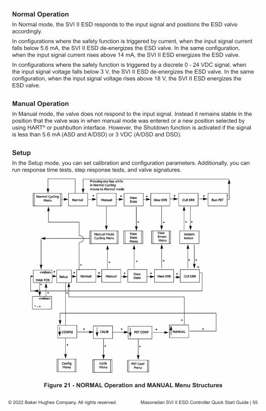
© 2022 Baker Hughes Company. All rights reserved. Masoneilan SVI II ESD Controller Quick Start Guide | 55
Normal OperationIn Normal mode, the SVI II ESD responds to the input signal and positions the ESD valve accordingly.
In configurations where the safety function is triggered by current, when the input signal current falls below 5.6 mA, the SVI II ESD de-energizes the ESD valve. In the same configuration, when the input signal current rises above 14 mA, the SVI II ESD energizes the ESD valve.
In configurations where the safety function is triggered by a discrete 0 - 24 VDC signal, when the input signal voltage falls below 3 V, the SVI II ESD de-energizes the ESD valve. In the same configuration, when the input signal voltage rises above 18 V, the SVI II ESD energizes the ESD valve.
Manual OperationIn Manual mode, the valve does not respond to the input signal. Instead it remains stable in the position that the valve was in when manual mode was entered or a new position selected by using HART® or pushbutton interface. However, the Shutdown function is activated if the signal is less than 5.6 mA (ASD and A/DSD) or 3 VDC (A/DSD and DSD).
SetupIn the Setup mode, you can set calibration and configuration parameters. Additionally, you can run response time tests, step response tests, and valve signatures.
Figure 21 - NORMAL Operation and MANUAL Menu Structures
56 | © 2022 Baker Hughes Company. All rights reserved.
ConfigurationTo perform configuration and calibration you can use either the pushbutton display, the HART® handheld communicator, a HART® Host with the DD loaded, or the ValVue ESD software. Refer to Pushbuttons and Local Display on page 50 or the SVI II ESD Instruction Manual SIL3, BHMN-SVI-ESD-18946 for instructions.
The following section describes configuration and calibration with the optional local display and pushbuttons.
WARNING These procedures can cause the valve to move. Before proceeding be sure the valve is isolated from the process. Keep hands clear from moving parts.
NOTE In this document, all calibration and configuration procedures are described using ValVue ESD software and an SVI II ESD with pushbuttons and display

© 2022 Baker Hughes Company. All rights reserved. Masoneilan SVI II ESD Controller Quick Start Guide | 57
Notes on Aggressiveness
ValVue ESD SoftwareValVue ESD provides advanced diagnostic, maintenance capabilities and complete calibration and configuration for the SVI II ESD. The software also performs Partial Stroke Testing (PST), scheduled and on demand, performs valve diagnostics (proof testing) and provides results in graphic, informational and historical formats. The software has a database to store test results for comparison with future results for predictive maintenance. It is password protected against access to remote instruments. It is set up with administration features.
Setting Aggressiveness While the SVI II ESD software and the DD allow you to set Aggressiveness, the pushbuttons do not. In all three methods, however, the Aggressiveness value is inherited from any previously performed tuning (Autotune or manual). Once Aggressiveness, and other tuning values are determined, they are stored in NVRAM.
The SVI II ESD provides a user define Aggressiveness Level for auto-tuning, the allowable range varies from -9 to +9 where 0 (Zero) is consider normal tuning. The Aggressiveness Level influences stroking speed and over-shoot. A negative value will SLOW stroking speed and help minimized over-shoot. A positive value will INCREASE stroking speed and may add some over-shoot.
The recommended values for Aggressiveness is 0 for control valves without volume boosters.
In applications with volume boosters and/or quick exhaust valves are used the Aggressiveness Level is not as influential. For Auto-tuning it is usually between 0 and 3. Reduce the volume boosters sensitivity by opening the integral bypass needle valve about 1 to 2 turns. Use caution when adjusting the needle valve so as to not to damage the seat, close gently to seat and then open 1 or 2 turns.
Aggressiveness Dynamic
Lower values of aggressiveness lead to lower PID values and slower response and less overshoot.
Higher values lead to higher PID values and quicker response and more overshoot.
Once you have a preferred aggressiveness and you tune once, all future autotunes automatically use that same value, until user-changed.

58 | © 2022 Baker Hughes Company. All rights reserved.
System RequirementsWindows® Server 2003 SP2, Windows® Server 2008, XP SP2, or 7, 64 MB RAM, a serial or USB port connected to a HART® modem.
Configuration with PushbuttonsTo change the current configuration parameters:
1. On power up if the SVI II ESD is not in NORMAL mode, switch to NORMAL mode. The display alternates between POS and SIGNAL indicating NORMAL mode.
2. Press + to access MANUAL mode.
3. With MANUAL mode displayed, press * to select the MANUAL mode the display alternates between POS –M and SIG indicating MANUAL mode.
4. Press * and SETUP appears.
5. Press * again; ↓CONFIG appears.
6. Press the * button to access the CONFIGuration menu.
7. Set the configuration parameters: Air Action, Air Pressure Units and Language. For each parameter:
a. Press * to access and change the parameter.
b. Press + to move to the next parameter.
c. Press + to return to SETUP.
d. Press + to return to NORMAL mode.
Viewing Configuration DataTo view SVI II ESD configuration data:
1. Access the VIEW DATA menu from the MANUAL menu by pressing the + button.
2. Press * to examine the configuration.
3. Press + to scroll through and observe the factory configuration.
4. Press + until MANPOS appears.
5. Select with *.
When the adjustment screen appears.
6. Stroke the valve open by holding + down. The rate of set point change is slow to begin, but increases speed while the + is pressed.
7. Stroke the valve to several values.
8. Verify the action is as desired.

© 2022 Baker Hughes Company. All rights reserved. Masoneilan SVI II ESD Controller Quick Start Guide | 59
Table 9 - VIEWDATA Settings
Viewing Status MessagesTo view SVI II ESD status messages:
1. Press + and * to select VIEW ERR.
2. Observe any internal errors. For example, there should be a RESET status caused by powering up. If the positioner was powered without air a Position Error or POSERR can appear.
3. Press + to view all faults.
4. Press * to return to MANual menu.
5. Press + until CLR ERR appears.
6. Press * CLR ERR. WAIT is displayed for a second or two.
Configuration Parameter
Typical Setting Optional Setting
Air Action ATO ATC
Air Pressure Units PSI BAR KPA
Language ENGLISH FRENCH, GERMAN, ITALIAN, PORTUGUESE, SPANISH, JAPANESE (simplified)

60 | © 2022 Baker Hughes Company. All rights reserved.
CalibrationWARNING In order to calibrate the SVI II ESD, it must be in
SETUP mode.
To calibrate the SVI II ESD:
1. On power up if the SVI II ESD is not in NORMAL mode, switch to NORMAL mode. The display alternates between POS and SIGNAL indicating NORMAL mode.
2. Press + to access MANUAL mode.
3. With MANUAL mode displayed, press * to select the MANUAL mode the display alternates between POS –M and SIG indicating MANUAL mode.
4. Press * and SETUP appears.
5. Press * again; ↓CONFIG appears.
6. Press + to display ↓CALIB.
7. Select CALIB by pressing *. STOPS appears.
8. Press * to activate the Find Stops calibration procedure. The valve moves full open and back to full closed.
9. Observe all warnings.
10. Press * to cause the valve to stroke and to automatically calibrate valve travel.
11. After the STOPS procedure finishes, press + twice until TUNE appears.
AutoTune and StopsThis procedure takes 3 to 10 minutes and strokes the valve in large and small steps to set the PID parameters for best positioning response.
To autoTUNE the SVI II ESD:
1. Press * to begin the autoTUNE procedure. Numerical messages display, indicating the procedure is working.
1. TUNE appears when autoTUNE is complete.
1. Press + repeatedly until ↑ SETUP appears.
1. Press * to return to SETUP menu ↓CALIB appears. The valve moves to the value set by the current calibrator.
2. Stroke the valve through its range to verify that the movement is as desired.
1. Press + to return to SETUP.
1. Press + to return to NORMAL mode.
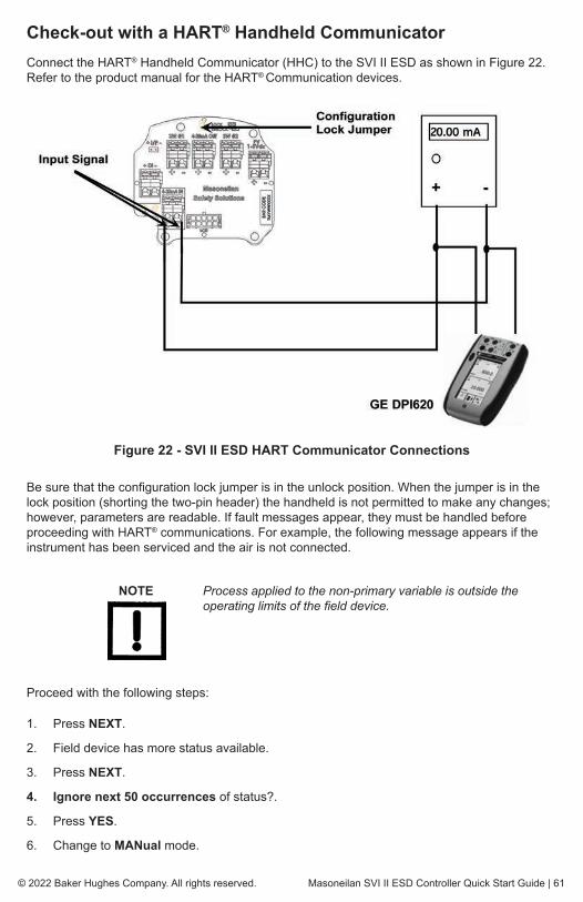
© 2022 Baker Hughes Company. All rights reserved. Masoneilan SVI II ESD Controller Quick Start Guide | 61
Check-out with a HART® Handheld CommunicatorConnect the HART® Handheld Communicator (HHC) to the SVI II ESD as shown in Figure 22. Refer to the product manual for the HART® Communication devices.
Figure 22 - SVI II ESD HART Communicator Connections
Be sure that the configuration lock jumper is in the unlock position. When the jumper is in the lock position (shorting the two-pin header) the handheld is not permitted to make any changes; however, parameters are readable. If fault messages appear, they must be handled before proceeding with HART® communications. For example, the following message appears if the instrument has been serviced and the air is not connected.
NOTE Process applied to the non-primary variable is outside the operating limits of the field device.
Proceed with the following steps:
1. Press NEXT.
2. Field device has more status available.
3. Press NEXT.
4. Ignore next 50 occurrences of status?.
5. Press YES.
6. Change to MANual mode.
62 | © 2022 Baker Hughes Company. All rights reserved.
HART Handheld Communicator Configuration (cont.)
7. Scroll to line 6 “EXAMINE”, press ->.
8. Scroll down to line 5 read status.
9. Read message.
10. Press OK.
11. Repeat OK to read all messages until the display returns to read status.
12. Scroll down to line 6 clear status, press ->.
13. If clear fault codes not completed appears, press OK and read the message (Position Error, for example) or go to the troubleshooting guide.
14. Correct the problem (Is the air supply on?), and then go to clear status until Clear Fault codes Completed appears.
15. Press OK
DiagnosticsThe SVI II ESD provides two types of diagnostic information; the continuous diagnostics that require no user configuration for which no valve movement occurs and Partial Stroke Testing (PST) diagnostics that you can configure and run at any time. You can also manually run a proof test (see page 16).
Partial Stroke Test DiagnosticsThe SVI II ESD is capable of partially stroking the valve to detect failures in the final control element assembly. The PST is configured using the pushbutton display or through ValVue ESD. Upon detection of a failure or deviation from the user configurable conditions the annunciation channel SW 1 sets its state to low.
The PST can be configured to start automatically or can be initiated through setting the current input to 16.4 mA. +/- 0.1mA, local control panel pushbutton, or initiated locally by an operator. When configured to run automatically or when initiated through a safety rated logic solver, additional diagnostic credit can be taken for the PST.
In addition to the safety rated I/O, HART® communications are available to provide additional information on the SVI II ESD status. Additional diagnostic functions include:
� With ASD or A/DSD modes, the device is capable of capturing and storing the shutdown event when the safety function is engaged and / or when the valve is positioned using the control signal (4-20 mA or 0-24 VDC).
� The SVI II ESD can provide general information of the device’s sensor health (Temperature, Actuator Pressure, Air supply, Current, etc.).
� Capable of annunciating faults resulting from a PST.
� Discrete output (SW1) is de-energized for any fault related to the I/P, relay, or valve/actuation assembly, resulting from a PST or during normal operation.
� For most fault conditions, the ESD device attempts to remain in the energized state until an ESD command is given (unless specified otherwise during setup).
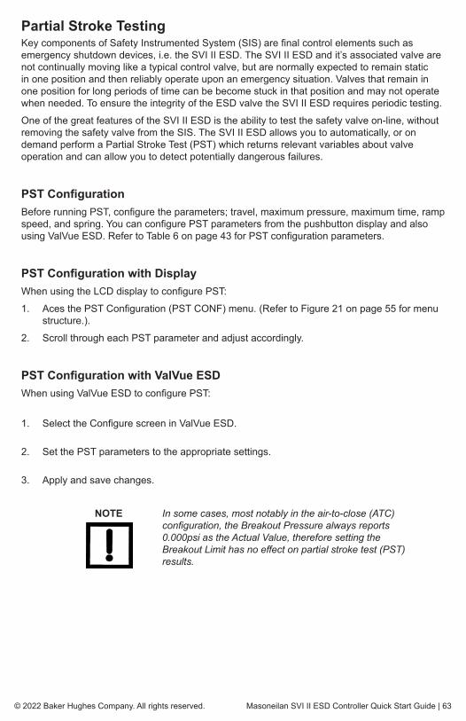
© 2022 Baker Hughes Company. All rights reserved. Masoneilan SVI II ESD Controller Quick Start Guide | 63
Partial Stroke TestingKey components of Safety Instrumented System (SIS) are final control elements such as emergency shutdown devices, i.e. the SVI II ESD. The SVI II ESD and it’s associated valve are not continually moving like a typical control valve, but are normally expected to remain static in one position and then reliably operate upon an emergency situation. Valves that remain in one position for long periods of time can be become stuck in that position and may not operate when needed. To ensure the integrity of the ESD valve the SVI II ESD requires periodic testing.
One of the great features of the SVI II ESD is the ability to test the safety valve on-line, without removing the safety valve from the SIS. The SVI II ESD allows you to automatically, or on demand perform a Partial Stroke Test (PST) which returns relevant variables about valve operation and can allow you to detect potentially dangerous failures.
PST ConfigurationBefore running PST, configure the parameters; travel, maximum pressure, maximum time, ramp speed, and spring. You can configure PST parameters from the pushbutton display and also using ValVue ESD. Refer to Table 6 on page 43 for PST configuration parameters.
PST Configuration with DisplayWhen using the LCD display to configure PST:
1. Aces the PST Configuration (PST CONF) menu. (Refer to Figure 21 on page 55 for menu structure.).
2. Scroll through each PST parameter and adjust accordingly.
PST Configuration with ValVue ESDWhen using ValVue ESD to configure PST:
1. Select the Configure screen in ValVue ESD.
2. Set the PST parameters to the appropriate settings.
3. Apply and save changes.
NOTE In some cases, most notably in the air-to-close (ATC) configuration, the Breakout Pressure always reports 0.000psi as the Actual Value, therefore setting the Breakout Limit has no effect on partial stroke test (PST) results.

64 | © 2022 Baker Hughes Company. All rights reserved.
Starting PSTThere are several methods to start a PST (summarized in Table 10):
� SVI II ESD pushbutton display by selecting “Run PST”. Refer to Figure 21 on page 55 for menu structure.
� ValVue ESD software interface (standalone or integrated with leading control systems). You can run the PST from the top level screen of ValVue ESD or on the PST screen.
� HART® handheld device, issuing a HART® command.
� Any HART® host with DD service. Download the DD from:
� https://valves.bakerhughes.com/resource-center.
� By issuing a loop current of 16.4 mA for 3 - 5 seconds (ASD or A/DSD models).
� Using the scheduler in SVI II ESD that automatically starts a PST at a specific date and time.
Table 10: PST Startup
PST Initialization PST Trigger or Launching Method
On Demand
Analog set to 16.4 mA
ValVue ESD
LCD
Handheld or any HART® Host with DD support
Scheduled Built-In calendar in SVI II ESD

© 2022 Baker Hughes Company. All rights reserved. Masoneilan SVI II ESD Controller Quick Start Guide | 65
This page intentionally left blank

66 | © 2022 Baker Hughes Company. All rights reserved.
Appendix A. Specifications and References
Physical and Operational SpecificationsThis section provides the physical and operational specifications for the SVI II ESD. Specifications are subject to change without notice.
Table 11: Environmental Specifications
Operating Temperature Limits -40°F to 185°F (-40°C to 85°C)
Storage Temperature Limits -58°F to 200°F (-50°C to 93°C)
Temperature Effect < 0.005% / °F typical; -40°F to 180°F (< 0.01% / °C typical; -40°C to 82°C)
Supply Pressure Effect 0.05% per psi (.73% per bar)
Relative Humidity 10 to 90% non-condensing
Humidity Effect Less than 0.2% after 2 days at 104°F (40°C), 95% Relative Humidity.
Insulation Resistance Greater than 10 G Ohms at 50% RH.
MTBF 49 years based on MIL handbook calculation for electronic parts and field data on mechanical parts
Electromagnetic Compatibility Electrostatic
Electrostatic discharge — No effect with contact discharge level of 4KV and air discharge level of 8 KV (IEC 1000-4-2)Radio frequency interference — Less than 0.2% at 10 volts per meter (EN 50140)
Fast Transient Burst No effect at 2 KV (Coupling clamp IEC 1000-4-4).
Vibration InfluenceMeasured at SVI II ESD Housing
4 mm at 5 - 15 Hz - Negligible2 G at 15 - 150 Hz Less than 2% of span1 G at 150 - 2000 Hz - Less than 2% of span
Magnetic Field InfluenceNegligible at 30 A/m (EN61000-4-8)CE MARK certified to EN50081-2 and EN50082-2

© 2022 Baker Hughes Company. All rights reserved. Masoneilan SVI II ESD Controller Quick Start Guide | 67
Table 12: Operational Specifications
Accuracy +/- 0.5% (typical +/-0. 10% or less) Full Span
Hysteresis and Deadband +/- 0.3% Full Span
Repeatability +/- 0.3% Full Span
Conformity +/- 0.5% Full Span
Start-Up Drift Less than 0.02% in first hour
Long Term Drift Less than 0.003% per month
Position Travel Limits
Rotary: 18 - 140°Reciprocating: 0.25” - 2.5“ (6 mm - 64 mm) Note: Above 2.5” (64 mm) consult factory for mounting instructions.
Position Auto TuneSVI II ESD performs automatic determination of the optimal valve position control parameters. In addition to P, I, D, the position algorithm uses damping, symmetry for exhaust and fill time constants, dead zone and magnitude characterization parameters. Auto Tune is optimized for 5% step changes with negligible overshoot. After the Auto Tune process is completed, you can further adjust the positioner tuning parameters to more conservative or to more responsive values.
Proportional gain: 0 to 5, displayed as 0 to 5000Integral time: 0 to 100 seconds - displayed as 0 to 1000 (1/10s)Derivative time: 0 to 200 milliseconds
Dead Zone: 0 to +/-5% (0 to 10% dead-band) Padj: +/- 3000 (depends on P)
Beta (non-linear gain factor): -9 to +9 Stroking Time: 0 to 250 secondsPosition compensation coefficient: 1 to 20Boost: 0 to 20
Start Up Time (from no power) Less than 200 mS
Minimum current to maintain HART® 3.0 mA

68 | © 2022 Baker Hughes Company. All rights reserved.
Table 13: Safety Rated Inputs
Table 14: Input Signal, Power, and Display Specifications
Device Terminal Signal Action Safety Integrity Level
ASD 4 - 20 mA IN < 5.6 mA De-energize to Trip 3
A/DSD 24 VDC IN < 3 VDC De-energize to Trip 3
DSD 24 VDC IN < 3 VDC De-energize to Trip 3
Power Supply Taken from 4-20 mA control signal
Compliance Voltage Rating
ASD - 9.6 V at 20 mA, 11.0 V at 4.0 mA
DSD - 24 V at 12 mA
A/DSD - 9.6 V at 20 mA, 11.0 V at 4.0 mA
Minimum Cut-off Current 3.2 mA
Wire Size 14/28 AWG
Strip Length 0.22” / 6 mm
Digital Communication
HART® Communication protocol signal from ValVue ESD software on a personal computer or a hand held device. HART® point to point and burst mode.
Local Display Liquid CrystalThree lines of nine alpha numeric characters. Display becomes unreadable between 0°C and -10°C. Display is shutdown at -15°C.
Push Buttons Three Explosion Proof / Flameproof push buttons

© 2022 Baker Hughes Company. All rights reserved. Masoneilan SVI II ESD Controller Quick Start Guide | 69
Table 15: Construction Material Specifications
Table 16: System Connectivity
Housing and CoverAluminum ASTM B85 Alloy SG100A standardStainless Steel optional (316L) Note: SST version is also SIL3
Weight Standard - 7.4 lbs./ 3.357 kg Stainless Steel - 16 lbs/ 7.257 kg
Relay and Manifold Single Acting - PPS, 300 Series Stainless Steel, nitrile diaphragms
I/P Motor 430 stainless steel, PPS, 300 series stainless steel
Mounting Bracket 300 series stainless steel
Magnet Holder Corrosion Protected Anodized Aluminum 6061 T6
Pole Ring 416 stainless steel
Levers 300 Series stainless steel
HART® Information HART® rev 5, ManufacturerID 0065, DeviceID 00CB
DD Registered with HART® Communication Foundation
Yes, from HART® Communication Foundation at www.hartcomm.org
Yokogawa PRM ValVue ESD Plug-In application available
Diagnostics
Valve signature, partial stroke test signature, emergency shutdown signature, stroking speed, friction high, friction low, valve breakout pressure, spring range, air supply droop, filling and exhaust rate. Integration of alarms with host using HART®
Command #48.
DD for Handheld Yes
HART CMD #3
HART® 4-20 mA input signal PV = Valve Position, 0-100% SV = Actuator Pressure (P1-P2) TV = Supply PressureQV = P2 for double acting units (not applicable)
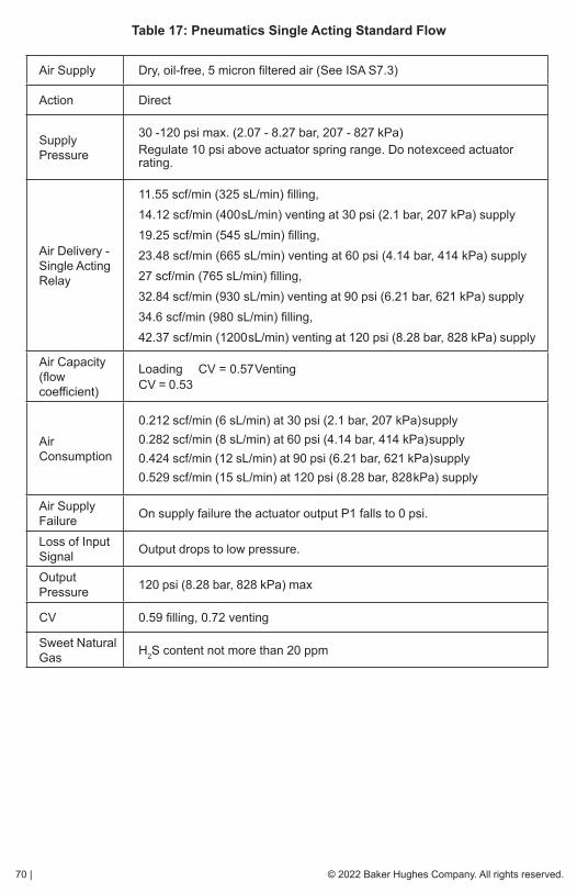
70 | © 2022 Baker Hughes Company. All rights reserved.
Table 17: Pneumatics Single Acting Standard Flow
Air Supply Dry, oil-free, 5 micron filtered air (See ISA S7.3)
Action Direct
Supply Pressure
30 -120 psi max. (2.07 - 8.27 bar, 207 - 827 kPa)Regulate 10 psi above actuator spring range. Do not exceed actuator rating.
Air Delivery - Single Acting Relay
11.55 scf/min (325 sL/min) filling, 14.12 scf/min (400 sL/min) venting at 30 psi (2.1 bar, 207 kPa) supply19.25 scf/min (545 sL/min) filling, 23.48 scf/min (665 sL/min) venting at 60 psi (4.14 bar, 414 kPa) supply 27 scf/min (765 sL/min) filling, 32.84 scf/min (930 sL/min) venting at 90 psi (6.21 bar, 621 kPa) supply34.6 scf/min (980 sL/min) filling, 42.37 scf/min (1200 sL/min) venting at 120 psi (8.28 bar, 828 kPa) supply
Air Capacity (flow coefficient)
Loading CV = 0.57 Venting CV = 0.53
Air Consumption
0.212 scf/min (6 sL/min) at 30 psi (2.1 bar, 207 kPa) supply0.282 scf/min (8 sL/min) at 60 psi (4.14 bar, 414 kPa) supply0.424 scf/min (12 sL/min) at 90 psi (6.21 bar, 621 kPa) supply0.529 scf/min (15 sL/min) at 120 psi (8.28 bar, 828 kPa) supply
Air Supply Failure On supply failure the actuator output P1 falls to 0 psi.
Loss of Input Signal Output drops to low pressure.
Output Pressure 120 psi (8.28 bar, 828 kPa) max
CV 0.59 filling, 0.72 venting
Sweet Natural Gas H2S content not more than 20 ppm

© 2022 Baker Hughes Company. All rights reserved. Masoneilan SVI II ESD Controller Quick Start Guide | 71
Hazardous Location Installation
WARNING Refer to ES-727 Safe Use Instructions for installing Masoneilan SVI II ESD in areas where there is a potential risk for explosive gas atmosphere or inflammable dust.
ES-727 instructions are available in several languages on:
valves.bakerhughes.com/resource-center

72 | © 2022 Baker Hughes Company. All rights reserved.
Appendix B. Optional Switch Load Limits
General Configuration NotesThe SVI II ESD supports two identical contact outputs, SW #1 and SW #2 (Digital Output switches), that can be logically linked to status bits.
The switches are polarity sensitive and must be connected only to a DC circuit. The switch (+) terminal must be electrically positive with respect to the (–) terminal. If the (+) terminal is electrically negative with respect to the (–) terminal, then the switch will conduct, regardless of switch state.
If the switch is connected directly across the power source, the current will be limited only by the capacity of the power source and the switch can be damaged.
This section discusses the necessary precautions when configuring a system.
Without a load, when the switch is on (closed) the external voltage would be dropped across the switch. This damages the switch (Figure 23).
Figure 23 - Switch Installation Drawing without Load: Configuration Not Allowed.
CAUTION Incorrect polarity connection results in an effectively closed connection.
CAUTION Consult with qualified personnel to ensure that electrical requirements for the switch are met.
SVI II ESD Switch Output
Full voltage drip is occurring across the switch (no current limit in place)
NOT ALLOWED
External Voltage Source
Switch OFF Switch ONVSWITCH 30 VDC max. ≤ 1 V (Switch saturation voltage)
ISWITCH≤ 0.200 mA (Switch leakage current) 1 A max.

© 2022 Baker Hughes Company. All rights reserved. Masoneilan SVI II ESD Controller Quick Start Guide | 73
The maximum voltage that can be applied to the digital switch outputs is 30 VDC. This is an open circuit parameter (the digital switch is in the open state). Under open circuit conditions, the switch current will be less than 0.200 mA.
The switch maximum current rating is 1 A. When the switch is ON, the typical switch voltage is
≤ 1V.
When the switch is on (closed) the external voltage must be dropped across the load (Figure 24).
CAUTION The load must be designed such that the current in the circuit is ≤ 1 A at all times. Some 3rd party devices, such as incandescent lamps or solenoids, require surge and back EMF protection to prevent voltage spikes.
Inductive Load, Solenoid, Incandescent Lamp Configuration
Load is designed to limit current through the switch to < 1A.
Figure 24 - Simplified Switch Installation Drawing: Correct Configuration
External Voltage Source
SVI II ESD Switch Output: ≤ 1V with Switch ON
If the load is inductive (solenoid, incandescent lamp, etc.), then install a Freewheel or Flyback diode to prevent switch damaging EMF voltage spikes.
LOAD
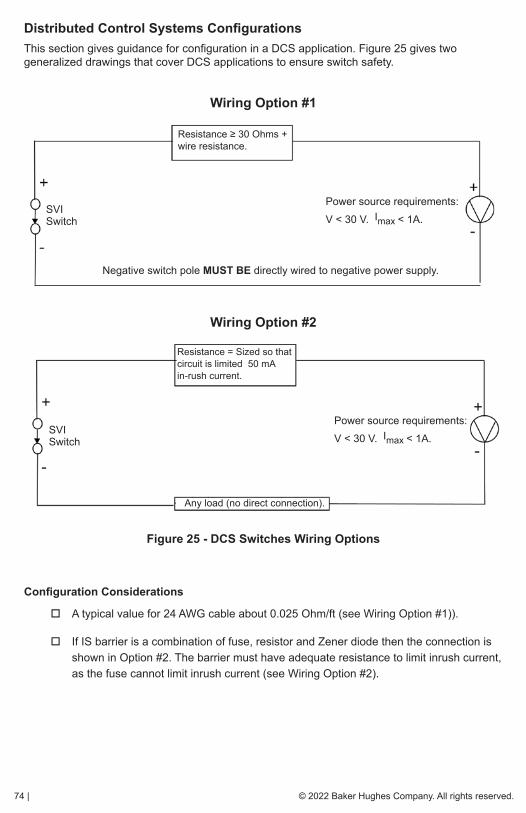
74 | © 2022 Baker Hughes Company. All rights reserved.
Distributed Control Systems ConfigurationsThis section gives guidance for configuration in a DCS application. Figure 25 gives two generalized drawings that cover DCS applications to ensure switch safety.
Wiring Option #1
Wiring Option #2
Figure 25 - DCS Switches Wiring Options
Configuration Considerations
� A typical value for 24 AWG cable about 0.025 Ohm/ft (see Wiring Option #1)).
� If IS barrier is a combination of fuse, resistor and Zener diode then the connection is shown in Option #2. The barrier must have adequate resistance to limit inrush current, as the fuse cannot limit inrush current (see Wiring Option #2).
Resistance ≥ 30 Ohms + wire resistance.
SVI Switch
Power source requirements:V < 30 V. Imax < 1A.
Negative switch pole MUST BE directly wired to negative power supply.
Resistance = Sized so that circuit is limited 50 mA in-rush current.
SVI Switch
Power source requirements:V < 30 V. Imax < 1A.
Any load (no direct connection).
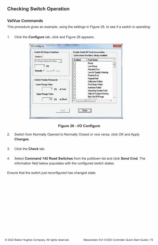
© 2022 Baker Hughes Company. All rights reserved. Masoneilan SVI II ESD Controller Quick Start Guide | 75
Checking Switch Operation ValVue CommandsThis procedure gives an example, using the settings in Figure 26, to see if a switch is operating:
1. Click the Configure tab, click and Figure 26 appears.
Figure 26 - I/O Configure
2. Switch from Normally Opened to Normally Closed or vice versa, click OK and Apply Changes.
3. Click the Check tab.
4. Select Command 142 Read Switches from the pulldown list and click Send Cmd. The information field below populates with the configured switch states.
Ensure that the switch just reconfigured has changed state.
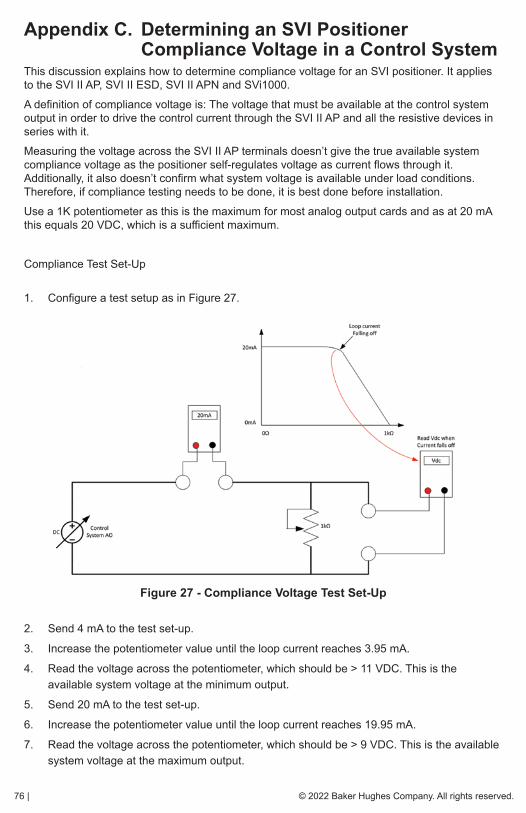
76 | © 2022 Baker Hughes Company. All rights reserved.
Appendix C. Determining an SVI Positioner Compliance Voltage in a Control SystemThis discussion explains how to determine compliance voltage for an SVI positioner. It applies to the SVI II AP, SVI II ESD, SVI II APN and SVi1000.
A definition of compliance voltage is: The voltage that must be available at the control system output in order to drive the control current through the SVI II AP and all the resistive devices in series with it.
Measuring the voltage across the SVI II AP terminals doesn’t give the true available system compliance voltage as the positioner self-regulates voltage as current flows through it. Additionally, it also doesn’t confirm what system voltage is available under load conditions. Therefore, if compliance testing needs to be done, it is best done before installation.
Use a 1K potentiometer as this is the maximum for most analog output cards and as at 20 mA this equals 20 VDC, which is a sufficient maximum.
Compliance Test Set-Up
1. Configure a test setup as in Figure 27.
Figure 27 - Compliance Voltage Test Set-Up
2. Send 4 mA to the test set-up.
3. Increase the potentiometer value until the loop current reaches 3.95 mA.
4. Read the voltage across the potentiometer, which should be > 11 VDC. This is the available system voltage at the minimum output.
5. Send 20 mA to the test set-up.
6. Increase the potentiometer value until the loop current reaches 19.95 mA.
7. Read the voltage across the potentiometer, which should be > 9 VDC. This is the available system voltage at the maximum output.

© 2022 Baker Hughes Company. All rights reserved. Masoneilan SVI II ESD Controller Quick Start Guide | 77
Table 18 lists some compliance voltage readings at positioner terminals at several currents.
Table 18: Expected Voltage Range at Positioner Terminals
CurrentCompliance Voltage
Requirement at Positioner Terminals
Expected Voltage Measured at Positioner Terminals
4 mA 11 V 10 to 11 V
8 mA 10.5 V 9.5 to 10.5 V
12 mA 10 V 9 to 10 V
16 mA 9.5 V 8.5 to 9.5 V
20 mA 9 V 8 to 9 V
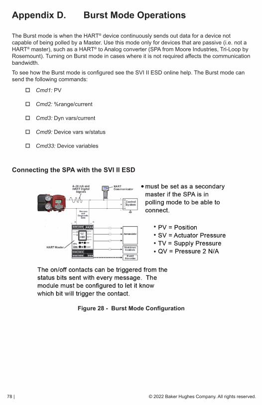
78 | © 2022 Baker Hughes Company. All rights reserved.
Appendix D. Burst Mode Operations
The Burst mode is when the HART® device continuously sends out data for a device not capable of being polled by a Master. Use this mode only for devices that are passive (i.e. not a HART® master), such as a HART® to Analog converter (SPA from Moore Industries, Tri-Loop by Rosemount). Turning on Burst mode in cases where it is not required affects the communication bandwidth.
To see how the Burst mode is configured see the SVI II ESD online help. The Burst mode can send the following commands:
� Cmd1: PV
� Cmd2: %range/current
� Cmd3: Dyn vars/current
� Cmd9: Device vars w/status
� Cmd33: Device variables
Connecting the SPA with the SVI II ESD
Figure 28 - Burst Mode Configuration
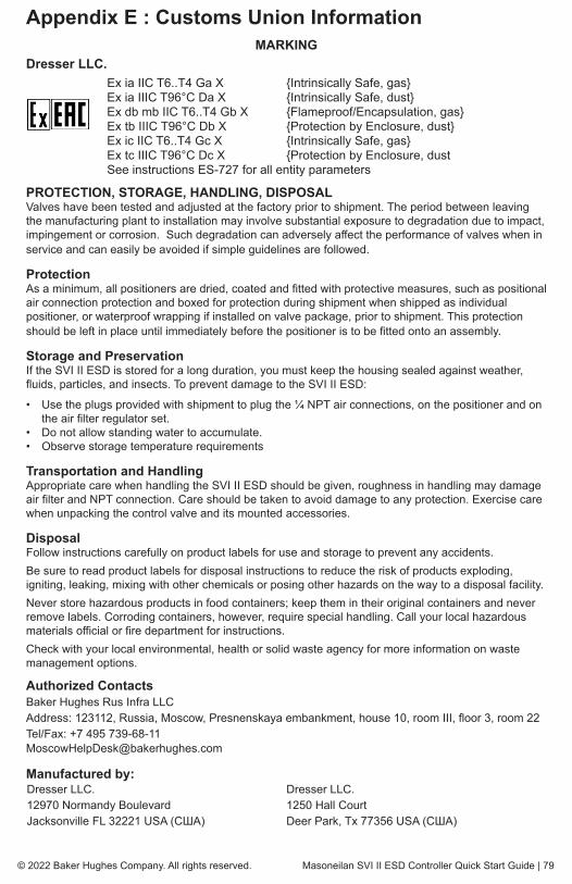
© 2022 Baker Hughes Company. All rights reserved. Masoneilan SVI II ESD Controller Quick Start Guide | 79
Appendix E : Customs Union InformationMARKING
Dresser LLC. Ex ia IIC T6..T4 Ga X {Intrinsically Safe, gas} Ex ia IIIC T96°C Da X {Intrinsically Safe, dust} Ex db mb IIC T6..T4 Gb X {Flameproof/Encapsulation, gas} Ex tb IIIC T96°C Db X {Protection by Enclosure, dust} Ex ic IIC T6..T4 Gc X {Intrinsically Safe, gas} Ex tc IIIC T96°C Dc X {Protection by Enclosure, dust See instructions ES-727 for all entity parameters
PROTECTION, STORAGE, HANDLING, DISPOSALValves have been tested and adjusted at the factory prior to shipment. The period between leaving the manufacturing plant to installation may involve substantial exposure to degradation due to impact, impingement or corrosion. Such degradation can adversely affect the performance of valves when in service and can easily be avoided if simple guidelines are followed.
ProtectionAs a minimum, all positioners are dried, coated and fitted with protective measures, such as positional air connection protection and boxed for protection during shipment when shipped as individual positioner, or waterproof wrapping if installed on valve package, prior to shipment. This protection should be left in place until immediately before the positioner is to be fitted onto an assembly.
Storage and PreservationIf the SVI II ESD is stored for a long duration, you must keep the housing sealed against weather, fluids, particles, and insects. To prevent damage to the SVI II ESD:
• Use the plugs provided with shipment to plug the ¼ NPT air connections, on the positioner and on the air filter regulator set.
• Do not allow standing water to accumulate.• Observe storage temperature requirements
Transportation and HandlingAppropriate care when handling the SVI II ESD should be given, roughness in handling may damage air filter and NPT connection. Care should be taken to avoid damage to any protection. Exercise care when unpacking the control valve and its mounted accessories.
DisposalFollow instructions carefully on product labels for use and storage to prevent any accidents.Be sure to read product labels for disposal instructions to reduce the risk of products exploding, igniting, leaking, mixing with other chemicals or posing other hazards on the way to a disposal facility.Never store hazardous products in food containers; keep them in their original containers and never remove labels. Corroding containers, however, require special handling. Call your local hazardous materials official or fire department for instructions.Check with your local environmental, health or solid waste agency for more information on waste management options.
Authorized ContactsBaker Hughes Rus Infra LLCAddress: 123112, Russia, Moscow, Presnenskaya embankment, house 10, room III, floor 3, room 22Tel/Fax: +7 495 739-68-11 [email protected]
Manufactured by:Dresser LLC.12970 Normandy BoulevardJacksonville FL 32221 USA (США)
Dresser LLC.1250 Hall CourtDeer Park, Tx 77356 USA (США)

bakerhughes.com
Copyright 2022 Baker Hughes Company. All rights reserved. Baker Hughes provides this information on an “as is” basis for general information purposes. Baker Hughes does not make any representation as to the accuracy or completeness of the information and makes no warranties of any kind, specific, implied or oral, to the fullest extent permissible by law, including those of merchantability and fitness for a particular purpose or use. Baker Hughes hereby disclaims any and all liability for any direct, indirect, consequential or special damages, claims for lost profits, or third party claims arising from the use of the information, whether a claim is asserted in contract, tort, or otherwise. Baker Hughes reserves the right to make changes in specifications and features shown herein, or discontinue the product described at any time without notice or obligation. Contact your Baker Hughes representative for the most current information. The Baker Hughes logo, Masoneilan, SVI, Camflex and ValVue are trademarks of Baker Hughes Company. Other company names and product names used in this document are the registered trademarks or trademarks of their respective owners.
BHMN-SVI-II-ESD-QSG-19520P-0422 04/2022
Tech Field Support & Warranty:Phone: +1-866-827-5378
Find the nearest local Channel Partner in your area:valves.bakerhughes.com/contact-us
valves.bakerhughes.com
Direct Sales Office LocationsAustraliaBrisbanePhone: +61-7-3001-4319
PerthPhone: +61-8-6595-7018
MelbournePhone: +61-3-8807-6002
BrazilPhone: +55-19-2104-6900
ChinaPhone: +86-10-8400-7888
FranceCourbevoiePhone: +33-1-4904-9000
IndiaMumbaiPhone: +91-22-8354790
New DelhiPhone: +91-11-2-6164175
ItalyPhone: +39-081-7892-111
JapanTokyo Phone: +81-03-6871-9008
KoreaPhone: +82-31-620-1736
MalaysiaPhone: +60-3-2161-03228
MexicoPhone: +52-55-3640-5060
RussiaVeliky NovgorodPhone: +7-8162-55-7898
MoscowPhone: +7-495-585-1276
Saudi ArabiaPhone: +966-3-341-0278
SingaporePhone: +65-6861-6100
South AfricaPhone: +27-83-387-9300
South & Central America and the CaribbeanPhone: +55-12-2134-1201
SpainPhone: +34-935-877-605
United Arab EmiratesPhone: +971-4-8991-777
United KingdomPhone: +44-7919-382-156
United StatesHouston, TexasPhone: +1-713-966-3600