Report_completo_corretto_17_1... - Stazione Zoologica Anton ...
Upload
khangminh22Category
view
2download
0
MANUALE STAZIONE DI SERVIZIO1Q0001xx
Vespa GTS Super 300 i.e.

MANUALESTAZIONE DI
SERVIZIO
Vespa GTS Super 300 i.e.
The descriptions and images in this publication are given for illustrative purposes only and are not binding.While the basic characteristics as described and illustrated in this booklet remain unchanged, Piaggio &C. S.p.A. reserves the right, at any time and without being required to update this publication beforehand,to make any changes to components, parts or accessories, which it considers necessary to improve the
product or which are required for manufacturing or construction reasons.Not all versions/models shown in this publication are available in all countries. The availability of each
model should be checked at the official PIAGGIO sales network.© Copyright 2014 - Piaggio & C. S.p.A. All rights reserved. Reproduction of this publication in whole or
in part is prohibited.Piaggio & C. S.p.A. Viale Rinaldo Piaggio, 25 - 56025 PONTEDERA (PI), Italy
www.piaggio.com

MANUALE STAZIONE DISERVIZIO
Vespa GTS Super 300 i.e.
Questo manuale per stazioni di servizio è stato realizzato da Piaggio & C. Spa per essere utilizzato dalleofficine dei concessionari e sub-agenzie Piaggio-Gilera. Si presuppone che chi utilizza questapubblicazione per la manutenzione e la riparazione dei veicoli Piaggio, abbia una conoscenza base deiprincipi della meccanica e dei procedimenti inerenti la tecnica della riparazione dei veicoli. Le variazioniimportanti nelle caratteristiche dei veicoli o nelle specifiche operazioni di riparazione verrannocomunicate attraverso aggiornamenti di questo manuale. Non si può comunque realizzare un lavorocompletamente soddisfacente se non si dispone degli impianti e delle attrezzature necessarie, ed è perquesto che vi invitiamo a consultare le pagine di questo manuale riguardanti l'attrezzatura specifica e ilcatalogo degli attrezzi specifici.
N.B. Provides key information to make the procedure easier to understand and carry out.
CAUTION Refers to specific procedures to carry out for preventing damages to the vehicle.
WARNING Refers to specific procedures to carry out to prevent injuries to the repairer.
Personal safety Failure to completely observe these instructions will result in serious risk of personalinjury.
Safeguarding the environment Sections marked with this symbol indicate the correct use of the vehicleto prevent damaging the environment.
Vehicle intactness The incomplete or non-observance of these regulations leads to the risk of seriousdamage to the vehicle and sometimes even the invalidity of the guarantee.

INDEX OF TOPICS
CHARACTERISTICS CHAR
TOOLING TOOL
MAINTENANCE MAIN
TROUBLESHOOTING TROUBL
ELECTRICAL SYSTEM ELE SYS
ENGINE FROM VEHICLE ENG VE
ENGINE ENG
INJECTION INJEC
SUSPENSIONS SUSP
BRAKING SYSTEM BRAK SYS
COOLING SYSTEM COOL SYS
CHASSIS CHAS
PRE-DELIVERY PRE DE

INDEX OF TOPICS
CHARACTERISTICS CHAR

This section describes the general specifications of the vehicle.
Rules
This section describes general safety rules for any maintenance operations performed on the vehicle.
Safety rules
- If work can only be done on the vehicle with the engine running, make sure that the premises are well
ventilated, using special extractors if necessary; never let the engine run in an enclosed area. Exhaust
fumes are toxic.
- The battery electrolyte contains sulphuric acid. Protect your eyes, clothes and skin. Sulphuric acid is
highly corrosive; in the event of contact with your eyes or skin, rinse thoroughly with abundant water
and seek immediate medical attention.
- The battery produces hydrogen, a gas that can be highly explosive. Do not smoke and avoid sparks
or flames near the battery, especially when charging it.
- Fuel is highly flammable and it can be explosive given some conditions. Do not smoke in the working
area, and avoid naked flames or sparks.
- Clean the brake pads in a well-ventilated area, directing the jet of compressed air in such a way that
you do not breathe in the dust produced by the wear of the friction material. Even though the latter
contains no asbestos, inhaling dust is harmful.
Maintenance rules
- Use original PIAGGIO spare parts and lubricants recommended by the Manufacturer. Non-original or
non-conforming spares may damage the vehicle.
- Use only the appropriate tools designed for this vehicle.
- Always use new gaskets, sealing rings and split pins upon refitting.
- After removal, clean the components using non-flammable or low flash-point solvents. Lubricate all
the work surfaces, except tapered couplings, before refitting these parts.
- After refitting, make sure that all the components have been installed correctly and work properly.
- Use only equipment with metric sizes for removal, service and reassembly operations. Metric bolts,
nuts and screws are not interchangeable with coupling members using English measurements. Using
unsuitable coupling members and tools may damage the vehicle.
- When carrying out maintenance operations on the vehicle that involve the electrical system, make
sure the electrical connections have been made properly, particularly the ground and battery connec-
tions.
Vespa GTS Super 300 i.e. Characteristics
CHAR - 7

Vehicle identification
Chassis prefix: ZAPM45100000 ÷ 1001
Engine prefix: M451M ÷ 1001
Dimensions and mass
WEIGHTS AND DIMENSIONSSpecification Desc./QuantityKerb weight 158 ± 5 kg
Maximum weight limit 340 kgMaximum height 1170 mm
Overall width 755 mmOverall length 2230 mm
Wheelbase 1370 mm
Characteristics Vespa GTS Super 300 i.e.
CHAR - 8

Engine
DATASpecification Desc./Quantity
Type single-cylinder, four-stroke and four liquid-cooled valvesCubic capacity 278.3 cm³
Stroke 63 mmBore 75 mm
MAX. torque 22 Nm at 6500 rpmMax. Power 16.4 kW at 7500 rpm
Timing system single overhead camshaft, chain-driven, on the left-hand side,three-arm rocking levers set up with threaded set screw
Compression ratio 10.5 ÷ 11.5Engine idle speed 1,650 ± 50 rpm
Air filter sponge, impregnated with mixture (50% petrol and 50% oil)Starting system electric starter motor with freewheel
Lubrication with lobe pump (inside the crankcase) chain-driven and doublefilter: mesh and paper
Fuel system Electronic injection with electric fuel pumpvalve clearance intake: 0.10 mm - exhaust: 0.15 mm
Minimum lubrication pressure (100° C) 0.8 barLubrication pressure 3.5 to 4 bar
Cooling Forced-circulation coolant system.
OIL PUMPSpecification Desc./Quantity
Type TrochoidalDistance between the rotors Admissible limit clearance: 0.12 mm
Axial rotor clearance Limit values admitted: 0.09 mmDistance between the outer rotor and the pump body Admissible limit clearance: 0.20 mm
Levelness 0.1 mm
BY-PASSSpecification Desc./Quantity
Type With pistonPlunger diameter Ø 13.9 - 0.039 -0.057 mm
By-pass check up: Standard length 54.2 mmCalibration pressure 4.5 bar
OIL FILTERSpecification Desc./Quantity
Type Paper with pressure relief and anti-drain back by-pass valves
OIL MINIMUM PRESSURE INDICATOR LIGHT SWITCHSpecification Desc./Quantity
Calibration 0.3 - 0.6 bar
HEAD LUBRICATION CONTROL JETSpecification Desc./Quantity
Diameter 1 ± 0.05 mm ** Tightening torque 5÷7 N·m
COOLING SYSTEMSpecification Desc./Quantity
Cooling system capacity ~ 2.100 ÷ 2.150 lRecommended fluid AGIP PERMANENT SPEZIAL
Sealing pressure Cap calibrated at 0.9 bar
Vespa GTS Super 300 i.e. Characteristics
CHAR - 9

THERMOSTATSpecification Desc./Quantity
Type Wax-type, with deviatorStarts opening at 85±2°C
ELECTRIC VENTILATIONSpecification Desc./Quantity
Electric ventilation starts at 102°CElectric ventilation stops at 96°C
WATER PUMPSpecification Desc./Quantity
Type CentrifugalControl Coaxial to crankshaft
RADIATORSpecification Desc./Quantity
Type Made of aluminium in two sections
Transmission
TRANSMISSIONSpecification Desc./QuantityTransmission Automatic expandable pulley CVT with torque server, V-belt,
automatic clutch, gear reduction unit and transmission com-partment with forced air circulation cooling
Capacities
CAPACITYSpecification Desc./Quantity
Fuel tank (including a ~ 2 l reserve) ~ 9.2 lCooling system fluid ~ 2.100 ÷ 2.150 l
Engine oil approx. 1300 ccRear hub 250 cc
Electrical system
ELECTRICAL COMPONENTSSpecification Desc./Quantity
Ignition/advance Electronic, with inductive discharge and variable advance withthree-dimensional mapping
Spark plug CHAMPION RG 4 PHPBattery 12V-12AhFuses One 30A fuse - One 15A fuse - Three 10A fuses - Four 7.5A
fuses - One 3A fuseGenerator alternating current
Characteristics Vespa GTS Super 300 i.e.
CHAR - 10

CHECKING RELAYS «A» OPERATING AS CIR-
CUIT BREAKERS
1) Check that, given regular conditions, there is no
continuity between terminals 30 and 87.
2) Apply 12V voltage to power terminals 85 and 86
of the relay.
3) With the relay powered, check that there is con-
tinuity between terminals 30 and 87.
4) If these conditions are not fulfilled, the relay is
damaged and must be replaced.
To check buttons and switches, check that, according to their position, the continuity of contacts is
correct as indicated in the following charts.
TURN INDICATORS SWITCH
ENGINE STOP SWITCH
HORN BUTTON
Vespa GTS Super 300 i.e. Characteristics
CHAR - 11
LIGHT SWITCH
STARTER BUTTON
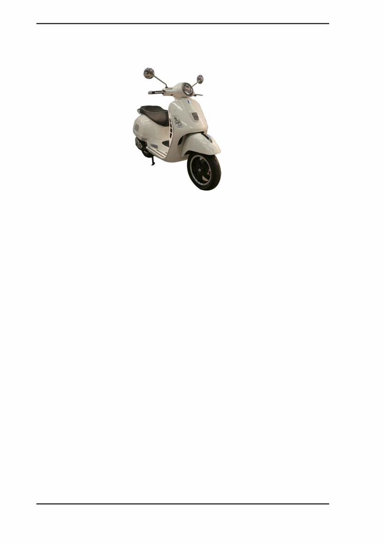
IGNITION SWITCH
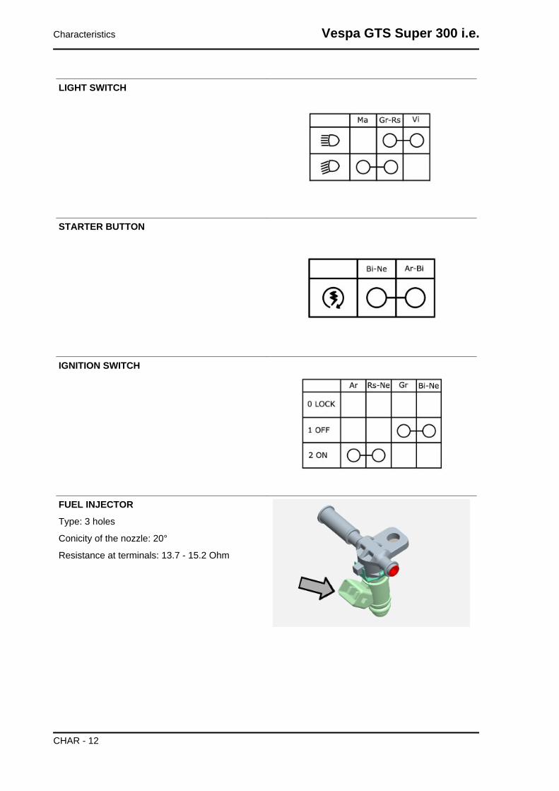
FUEL INJECTOR
Type: 3 holes
Conicity of the nozzle: 20°
Resistance at terminals: 13.7 - 15.2 Ohm
Characteristics Vespa GTS Super 300 i.e.
CHAR - 12

FUEL PUMP UNIT
Mechanical type pressure regulator operating at a
pressure of 2.5 BAR
Pump winding resistance: ~ 1.5 Ohm
Input current during regular functioning: 1.4 - 1.8
A
SPEED/PHASE SENSOR
Resistance between pins 13 and 15: 100 to 150
Ohm at approx. 20°
ENGINE TEMPERATURE SENSOR
0° = 5,900 Ohm
+10° = 3,800 Ohm
+20° = 2,500 Ohm
+30° = 1,700 Ohm
+80° = 300 Ohm
MINIMUM OIL PRESSURE SENSOR
Normally closed switch
Activation threshold: 0.3 - 0.6 BAR
With the engine off: continuity between muffler and
ground
H.V. COIL
<DIV class=O v:shape="_x0000_s3074">
- Resistance of the primary = 0.5 Ohm ± 8%
- Resistance between primary and ground = infinite
- Resistance between primary and H.V. output = 3.1KOhm ± 9%
Vespa GTS Super 300 i.e. Characteristics
CHAR - 13

- Presence of battery voltage between pins 22 and
26 of the interface cable harness upon
shifting to ON and for 2 sec.
STATOR
Power: 450 W
Resistance between terminals: 0.2 - 1 Ohm
terminal insulation from ground
Frame and suspensions
CHASSIS AND SUSPENSIONSSpecification Desc./Quantity
Type Unitised body made of stamped plateFront suspension Single arm suspension (cantilever wheel) fitted with a double-
acting hydraulic shock absorber with coaxial springFront shock absorber axial travel 86.5 mm
Rear suspension Engine with swinging fork articulated to frame by means of anarm with 2 degrees of freedom Pair of double-acting hydraulicshock absorbers and coaxial springs with preloading adjust-
ment in 4 positions.Rear shock absorber axial travel 89.5 mm
Brakes
BRAKESSpecification Desc./Quantity
Front Ø 220 disc brake and floating calliper with Ø 25 mm twin plung-ers and hydraulic control (lever on the far right end of the
handlebar)Rear Ø 220 disc brake and calliper with two Ø 30 mm counteracting
plungers and hydraulic control (lever on the far left end of thehandlebar)
Characteristics Vespa GTS Super 300 i.e.
CHAR - 14

Wheels and tyres
WHEELS AND TYRESSpecification Desc./Quantity
Front wheels - light alloy rims 3.00x12Rear wheels - light alloy rims 3.00x12
Front tyres 120/70-12" TubelessRear tyres 130/70-12" Tubeless
TYRE PRESSURESpecification Desc./Quantity
Front tyre pressure (when cold) 1.8 barRear tyre pressure (when cold) 2 bar
Tyre pressure (when cold) with passenger 2.2 barN.B.
CHECK AND ADJUST TYRE PRESSURE WITH TYRES AT AMBIENT TEMPERATURE. REGU-LATE PRESSURE ACCORDING TO THE WEIGHT OF BOTH RIDER AND ACCESSORIES
Tightening Torques
STEERING ASSEMBLYName Torque in Nm
Upper steering ring nut 35 to 40Lower steering ring nut 12 - 14Handlebar fixing screw 50 ÷ 55
Fixing screws for the handlebar control unit U-bolts 7 to 10
CHASSIS ASSEMBLYName Torque in Nm
Engine-swinging arm pin 64 - 72swinging arm bolt - body shell 76 ÷ 83
Engine and vehicle side swinging arm junction bolt 33 to 41Bolt of the Silent block support plate 42 ÷ 52
Centre stand bolt 32 - 40Side stand fixing bolt 35 - 40
FRONT SUSPENSIONName Torque in Nm
Screw fixing the shock absorber to the shock absorber - calliperattachment plate
20 to 27
Wheel axle nut 74 to 88Wheel screw 20 - 25
Screw fixing rear mudguard to steering 5 - 6.5shock absorber upper clamp 20 to 30
FRONT BRAKEName Torque in Nm
Brake fluid pump-hose fitting 20 to 25Brake fluid pipe-calliper fitting 19 ÷ 24
Screw fixing calliper to the shock absorber - calliper plate at-tachment
24 to 27
Disc tightening screw 6 (Apply LOCTITE 242 threadlock, medium strength)Oil bleed screw 12 - 16
Pad fastening pin 19.6 ÷ 24.5Brake pump reservoir screws 1.5 ÷ 2
Brake disc screws 8 ÷ 10
Vespa GTS Super 300 i.e. Characteristics
CHAR - 15
REAR SUSPENSIONName Torque in Nm
Retainer for left shock absorber to crankcase support plate 20 to 25Shock absorber lower fitting 40 to 45Shock absorber upper fitting 20 to 25
Rear wheel axle 104 to 126Screw fixing wheel to hub 20 to 25
Screws for silencer - shock absorber support arm on engine 20 ÷ 25 (The two screws must be tightened after having doneso with the rear wheel axle nut at the specified torque. Safety
fasteners: see «Pre-delivery Operations»)Engine- and vehicle-side swinging arm junction bolt 40 to 45
REAR BRAKEName Torque in Nm
Brake fluid pump-hose joint 20 - 25Brake fluid pipe-calliper fitting 20 - 25
Rear disc tightening bolt 11 to 13Oil bleed screw 12÷16
Calliper to engine tightening screw 20 to 25Brake pump reservoir screws 1.5 ÷ 2
Calliper coupling screw 30 ÷ 33
SILENCERName Torque in Nm
Silencer heat guard fixing screw 4 ÷ 5Screw for fixing silencer to supporting arm 20 - 25
Oxygen sensor tightening on exhaust manifold 40 - 50Exhaust manifold-silencer joint tightening 12 to 13
Manifold - silencer diaphragm tightening clamp 16 - 18
LUBRICATIONName Torque in Nm
Hub oil drainage plug 15 to 17Oil filter on crankcase fitting 27 - 33
engine oil drainage plug/mesh filter 24 to 30Oil filter 4 to 6
Oil pump cover screws 7 - 9Screws fixing oil pump to crankcase 5 - 6oil pump driving crown gear screw 10 - 14
Oil pump cover plate screws 4 to 6Oil sump screws 10 - 14
Minimum oil pressure sensor 12 - 14
CYLINDER HEADName Torque in Nm
Spark plug 12 - 14Cylinder head cover screws 6 - 7
Head to cylinder retaining nuts 7±1 + 10±1 + 270°Head side fixing screws 11 - 12
Starter ground screw 7 to 8.5Tappet set screw lock nut 6 to 8
Inlet manifold screws 11 - 13Timing chain tensioner pad screw 10 - 14
Starter ground bell screw 11 to 15Timing chain tensioner support screw 11 - 13Timing chain tensioner central screw 5 - 6
Camshaft retention plate screw 4 to 6
TRANSMISSIONName Torque in Nm
Belt support roller screw 11 - 13Clutch assembly nut on driven pulley 45 - 50
Characteristics Vespa GTS Super 300 i.e.
CHAR - 16
Name Torque in NmDriving pulley nut 75 - 83
Transmission cover screws 11 - 13Driven pulley shaft nut 54 - 60Rear hub cover screws 24 - 27
FLYWHEELName Torque in Nm
Flywheel cover screw 11 - 13Stator unit screws 3 - 4 (Apply LOCTITE medium type 242 threadlock)
Flywheel nut 94 - 102Pick-Up fixing screws 3 - 4
Screws fixing freewheel to flywheel 13 to 15
CRANKCASE AND CRANKSHAFTName Torque in Nm
Screws for engine crankcase internal bulkhead (transmission-side half shaft)
4 to 6
Engine crankcase coupling screws 11 - 13Starter motor screws 11 - 13
Crankcase timing cover screws 3.5 - 4.5 (Apply LOCTITE medium type 242 threadlock)
COOLINGName Torque in Nm
Water pump rotor cover 3 - 4Thermostat cover screws 3 - 4
Bleed screw 3
Versions for market USA-CND
STEERING ASSEMBLYName Torque in Nm
Upper steering ring nut 25.8 - 29.5 lb*ftLower steering ring nut 8.9 - 10.3 lb*ftHandlebar fixing screw 36.9 - 40.6 lb*ft
Handlebar and control unit U-bolts 5.2 - 7.4 lb*ft
FRAME ASSEMBLYName Torque in Nm
Engine-swinging arm pin 49.4 - 55.3 lb*ftSwinging arm bolt - body shell 56.0 - 61.2 lb*ft
Engine and vehicle side swinging arm junction bolt 29.5 - 33.2 lb*ftSilent-block support plate to frame 31.0 - 38.4 lb*ft
Centre stand fixing 23.6 - 29.5 lb*ftSide stand clamp 25.8 - 29.5 lb*ft
FRONT SUSPENSIONName Torque in Nm
Lower shock absorber clamp 14.8 - 19.9 lb*ftWheel axle 54.6 - 64.9 lb*ft
Wheel to hub 14.8 - 18.4 lb*ftFront mudguard retainer 3.7 - 4.8 lb*ft
Upper shock absorber retainer 14.8 - 22.1 lb*ft
FRONT BRAKEName Torque in Nm
Brake fluid hose-pump fitting 14.8 - 18.4 lb*ftBrake fluid pipe-calliper fitting 14.0 - 17.7 lb*ft
Clamp to shock absorber plate tightening 17.7 - 19.6 lb*ftOil bleed screw 8.9 - 11.8 lb*ft
Pad fastening pin 14.5 - 18.1 lb*ft
Vespa GTS Super 300 i.e. Characteristics
CHAR - 17

Name Torque in NmBrake pump tray 1.1 - 1.5 lb*ftFront brake disc 5.9 - 7.4 lb*ft
REAR SUSPENSIONName Torque in Nm
left shock absorber to crankcase support plate fixing 14.8 - 18.4 lb*ftLower shock absorber clamp 29.5 - 33.2 lb*ft
Upper shock absorber retainer 14.8 - 18.4 lb*ftRear wheel axle 76.7 - 92.9 lb*ft
Wheel to hub 14.8 - 18.4 lb*ftShock absorber support arm on engine 14.8 - 18.4 lb*ft
Engine- and vehicle-side swinging arm junction bolt 29.5 - 33.2 lb*ft
REAR BRAKEName Torque in Nm
Brake fluid hose-pump fitting 14.8 - 18.4 lb*ftBrake fluid pipe-calliper fitting 14.8 - 18.4 lb*ft
Rear disc tightening 8.1 - 9.6 lb*ftOil bleed 8.9 - 11.8 lb*ft
Brake calliper to engine 14.8 - 18.4 lb*ftBrake pump tray 1.1 - 1.5 lb*ftCalliper coupling 22.1 - 24.3 lb*ft
SILENCERName Torque in Nm
Muffler heat guard fixing 3.0 - 3.7 lb*ftFixing silencer to supporting arm 14.8 - 18.4 lb*ft
Lambda probe on manifold 29.5 - 36.9 lb*ftExhaust manifold-silencer joint 8.9 - 9.6 lb*ft
Manifold-silencer clamp tightening 11.8 - 13.3 lb*ft
LUBRICATIONName Torque in Nm
Hub oil drainage plug 11.1 - 12.5 lb*ftOil filter fitting on crankcase 19.9 - 24.3 lb*ft
engine oil drainage plug/mesh filter 17.7 - 22.1 lb*ftOil filter 3.0 - 4.4 lb*ft
Oil pump cover 5.2 - 6.6 lb*ftPump to crankcase fixing 3.7 - 4.4 lb*ft
Oil pump driving crown gear 7.4 - 10.3 lb*ftOil pump cover plate 3.0 - 4.4 lb*ft
Oil sump 7.4 - 10.3 lb*ftOil pressure sensor 8.9 - 10.3 lb*ft
CYLINDER HEADName Torque in Nm
Spark plug 8.9 - 10.3 lb*ftHead cover 4.4 - 5.2 lb*ft
Head fixing nuts 4.4 - 5.9 + 6.6 - 8.1 lb*ft + 270°Head side fixing screws 8.1 - 8.9 lb*ft
Starter grounds 5.2 - 6.3 lb*ftTappet set screw lock nut 4.4 - 5.9 lb*ft
Intake manifold 8.1 - 9.6 lb*ftTiming chain tensioner slider 7.4 - 10.3 lb*ft
Starter grounds housing 8.1 - 11.1 lb*ftTiming chain tensioner support 8.1 - 9.6 lb*ft
Timing chain tensioner central screw 3.7 - 4.4 lb*ftCamshaft retention plate 3.0 - 4.4 lb*ft
TRANSMISSIONName Torque in Nm
Belt support roller 8.1 - 9.6 lb*ft
Characteristics Vespa GTS Super 300 i.e.
CHAR - 18

Name Torque in NmClutch assembly on driven pulley 33.6 - 36.9 lb*ft
Driving pulley 55.3 - 61.2 lb*ftTransmission cover 8.1 - 9.6 lb*ftDriven pulley axle 39.8 - 44.3 lb*ftRear hub cover 17.7 - 19.9 lb*ft
FLYWHEELName Torque in Nm
Flywheel cover 8.1 - 9.6 lb*ftStator assembly* 2.2 - 3.0 lb*ft
FLYWHEEL 69.3 - 75.2 lb*ftPick-up fixing 2.2 - 3.0 lb*ft
Freewheel to flywheel fixing 9.6 - 11.1 lb*ft
CRANKCASE AND CRANKSHAFTName Torque in Nm
Engine crankcase internal 3.4 - 4.4 lb*ftCrankcase coupling 8.1 - 9.6 lb*ftSTARTER MOTOR 8.1 - 9.6 lb*ft
Crankcase timing cover* 2.6 - 3.3 lb*ft
COOLINGName Torque in Nm
Water pump rotor cover 2.2 - 3.0 lb*ftThermostat cover 2.2 - 3.0 lb*ft
Bleed screw 2.2 lb*ft
(*) with Loctite 243
Overhaul data
Assembly clearances
Cylinder - piston assy.
Vespa GTS Super 300 i.e. Characteristics
CHAR - 19

CYLINDER - PISTONSpecification Desc./Quantity
Plunger diameter 74.967 +0.014 -0.014 mmCylinder diameter 75 +0.038 +0.01 mm
COUPLING CATEGORIESName Initials Cylinder Piston Play on fitting
cylinder-piston M 75.01 ÷ 75.017 74.953 ÷ 74.960 0.050 ÷ 0.064cylinder-piston N 75.017 ÷ 75.024 74.960 ÷ 74.967 0.050 ÷ 0.064cylinder-piston O 75.024 ÷ 75.031 74.967 ÷ 74.974 0.050 ÷ 0.064cylinder-piston P 75.031 ÷ 75.038 74.974 ÷ 74.981 0.050 ÷ 0.064
N.B.
THE PISTON MUST BE INSTALLED WITH THE ARROW FACING TOWARDS THE EXHAUST SIDE,THE PISTON RINGS MUST BE INSTALLED WITH THE WORD «TOP» OR THE STAMPED MARKFACING UPWARDS.
- Measure the outer diameter of the gudgeon pin.
CharacteristicPin outside diameter16 +0 -0.004 mm
- Measure the diameter of the bearings on the pis-
ton.
CharacteristicStandard diameter16 +0.006 +0.001 mm
- Calculate the pin - piston coupling clearance.N.B.
THE PIN HOUSINGS HAVE TWO LUBRICATION CHANNELS FOR THIS REASON MEASURE THEDIAMETER ACCORDING TO THE PISTON AXIS
CharacteristicStandard clearance:
0.001 - 0.010 mm
Characteristics Vespa GTS Super 300 i.e.
CHAR - 20

- Carefully clean the seal housings.
- Measure the coupling clearance between the
sealing rings and the piston grooves using suitable
sensors, as shown in the diagram.
- If the clearance is greater than that indicated in
the table, replace the piston.N.B.MEASURE CLEARANCE BY INSERTING THE BLADE OFTHE FEELER GAUGE FROM THE 2nd SEALING RINGSIDE.
Fitting clearance1st compression ring - standard couplingclearance 0.015 - 0.06 mm 1st compression ring -maximum clearance allowed after use 0.07 mm2nd compression ring - standard couplingclearance 0.015 - 0.06 mm 2nd compression ring -maximum clearance allowed after use 0.07 mmoil scraper ring - standard coupling clearance0.015 - 0.06 mm oil scraper ring - maximum clear-ance allowed after use 0.07 mm
- Check that the head coupling surface is not worn
or misshapen.
- Pistons and cylinders are classified according to
their diameter. The coupling must be made with
those of the same type (M-M, N-N, O-O, P-P).
CharacteristicMaximum run-out allowed:0.001 in 0.05 mm
Piston rings
Sealing rings
- Alternately insert the three sealing rings into the
cylinder, in the area where it retains its original di-
ameter. Using the piston, insert the rings perpen-
dicularly to the cylinder axis.
- Measure the opening (see figure) of the sealing
rings using a feeler gauge.
- If any measurements are greater than specified,
replace the piston rings.N.B.BEFORE REPLACING ONLY THE PISTON RINGS, ENSURETHAT THE CLEARANCE BETWEEN THE PISTON RINGSAND THE PISTON RING GROOVES, AND BETWEEN THEPISTON AND THE CYLINDER, IS AS SPECIFIED. IN ANY
Vespa GTS Super 300 i.e. Characteristics
CHAR - 21
CASE, NEW PISTON RINGS USED IN COMBINATION WITHA USED CYLINDER MAY HAVE DIFFERENT BEDDINGCONDITIONS THAN THE STANDARD.
CharacteristicTop piston ringStandard opening: 0.15 to 0.30 mm
Middle piston ringStandard opening: 0.20 ÷ 0.40 mm
scraper ringStandard opening: 0.20 ÷ 0.40 mm
Crankcase - crankshaft - connecting rod
CRANKSHAFTTitolo Durata/Valore Testo Breve (< 4000 car.) Indirizzo Immagine
Crankshaft Crankshaft to connecting rodaxial clearance
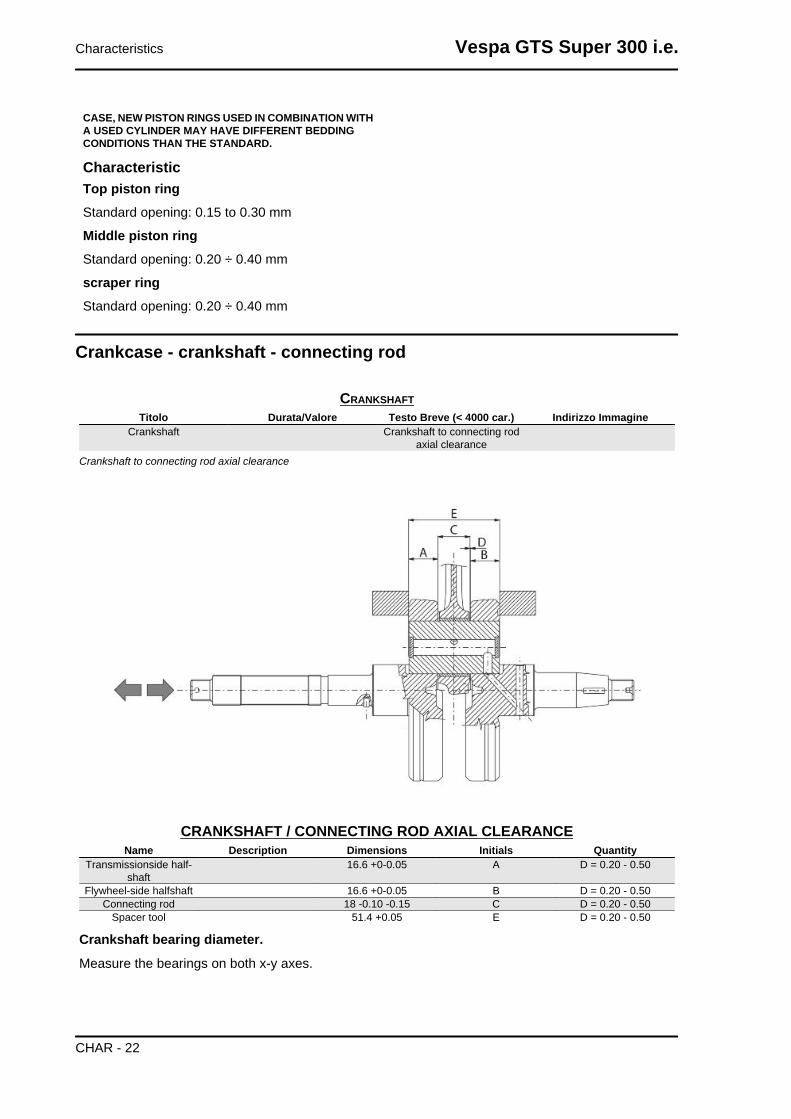
Crankshaft to connecting rod axial clearance
CRANKSHAFT / CONNECTING ROD AXIAL CLEARANCEName Description Dimensions Initials Quantity
Transmissionside half-shaft
16.6 +0-0.05 A D = 0.20 - 0.50
Flywheel-side halfshaft 16.6 +0-0.05 B D = 0.20 - 0.50Connecting rod 18 -0.10 -0.15 C D = 0.20 - 0.50
Spacer tool 51.4 +0.05 E D = 0.20 - 0.50
Crankshaft bearing diameter.
Measure the bearings on both x-y axes.
Characteristics Vespa GTS Super 300 i.e.
CHAR - 22

CRANKSHAFTSpecification Desc./Quantity
Crankshaft bearings: Standard diameter: Cat. 1 28.998 ÷ 29.004 mmCrankshaft bearings: Standard diameter: Cat. 2 29.004 ÷ 29.010 mm
Vespa GTS Super 300 i.e. Characteristics
CHAR - 23

MAXIMUM OFF-LINE ALLOWEDSpecification Desc./Quantity
A = 0.15 mmB = 0.010 mmC = 0.010 mmD = 0.10 mm
Characteristics Vespa GTS Super 300 i.e.
CHAR - 24

CharacteristicCrankshaft-crankcase axial clearance (H)
0.15 ÷ 0.43 mm
- Using a bore gauge, measure the connecting rod
small end diameter.N.B.IF THE CONNECTING ROD SMALL END DIAMETER EX-CEEDS THE STANDARD DIAMETER, SHOWS SIGNS OFWEAR OR OVERHEATING, REPLACE THE CRANKSHAFTAS DESCRIBED IN THE «CRANKCASE AND CRANK-SHAFT» CHAPTER.
CharacteristicStandard diameter16 +0.025 +0.015 mm
- To obtain a good bushing lubrication it is necessary to have both an optimal lubricating pressure and
a good oil flow rate; the bushings must be correctly positioned so as not to obstruct the oil supply
channels.
- The main bushings are comprised of two half-bearings, one with holes and channels for lubrication
whereas the other is solid.
- The solid half-bearing is intended to stand the thrusts caused by combustion, and for this reason it is
arranged opposite the cylinder.
- To prevent shutters in the oil feeding channels, the matching surface of the two half-bearings must be
perfectly orthogonal to the cylinder axis, as shown in the figure.
- The oil feeding channel section is also affected by the bushings driving depth compared with the
crankshaft axial clearance of the limiting surface.
- Check the inside diameter of the main bushings in the three directions indicated in the diagram.
- Repeat the measurements for the other bushing half. see diagram.
- There are three crankcase versions: with BLUE, YELLOW or GREEN bushings.
- There is just one type of bushing housing in the crankcase. The standard diameter of the bushings
after fitting depends on the choice of coupling.
- There are 2 categories of bushing seats in the crankcase - Cat 1 and Cat 2 - just like those for the
crankshaft
- The main bushings are subdivided into 3 categories according to thickness; see table below:
BUSHINGSTYPE IDENTIFICATION CRANKSHAFT HALF-BEARING
B BLUE 1.973 - 1.976C YELLOW 1.976 - 1.979E GREEN 1.979 - 1.982
COMBINATIONSBUSHING CATEGORY CRANKCASE
HALVES CATEGORYBUSHING INSIDE DIAMETER AFTER FITTING
B 2 29.024 ÷ 29.054
Vespa GTS Super 300 i.e. Characteristics
CHAR - 25

BUSHING CATEGORY CRANKCASEHALVES CATEGORY
BUSHING INSIDE DIAMETER AFTER FITTING
C 1 29.024 ÷ 29.0542 29.018 ÷ 29.048
E 1 29.018 ÷ 29.048
Combine the crankshaft with two crankwebs category 1 with a crankcase category 1 (or cat. 2 with cat.
2) A spare crankcase cannot be combined with a crankshaft with mixed categories. Spare shafts have
half-shafts of the same category.
CATEGORIESCRANKCASE HALVES ENGINE HALF-SHAFT BUSHING
Cat. 1 Cat. 1 ECat. 2 Cat. 2 BCat. 1 Cat. 2 CCat. 2 Cat. 1 CN.B.DO NOT TAKE THE MEASUREMENT ON THE TWO HALF-SHELL COUPLING SURFACE SINCE THE ENDS ARE RE-LIEVED TO ALLOW BENDING DURING THE DRIVINGOPERATION.N.B.SPARE CRANKCASES ARE SELECTED WITH CRANK-CASE HALVES OF THE SAME CATEGORY AND ARE FIT-TED WITH CATEGORY C (YELLOW) BUSHINGS
CharacteristicCrankshaft-bushing maximum clearance al-lowed:0.08 mm
Diameter of crankcase without bushingCAT 1: 32.959 ÷ 32.965 mmCAT 2: 32.953 ÷ 32.959 mm
Cylinder Head
Clean all the coupling surfaces thoroughly before servicing the head. Pay attention to the position of
the springs and valves so as not to change the original position upon refitting them
- Using a trued bar and a thickness gauge, check
that the cylinder head surface is not worn or dis-
torted.
CharacteristicMaximum run-out allowed:0.1 mm
- In case of irregularities, replace the head.
- Check the sealing surfaces for the inlet and exhaust manifold.
- Check that the camshaft and the rocker pin bearings show no signs of wear.
- Check that the head cover show no signs of wear.
Characteristics Vespa GTS Super 300 i.e.
CHAR - 26
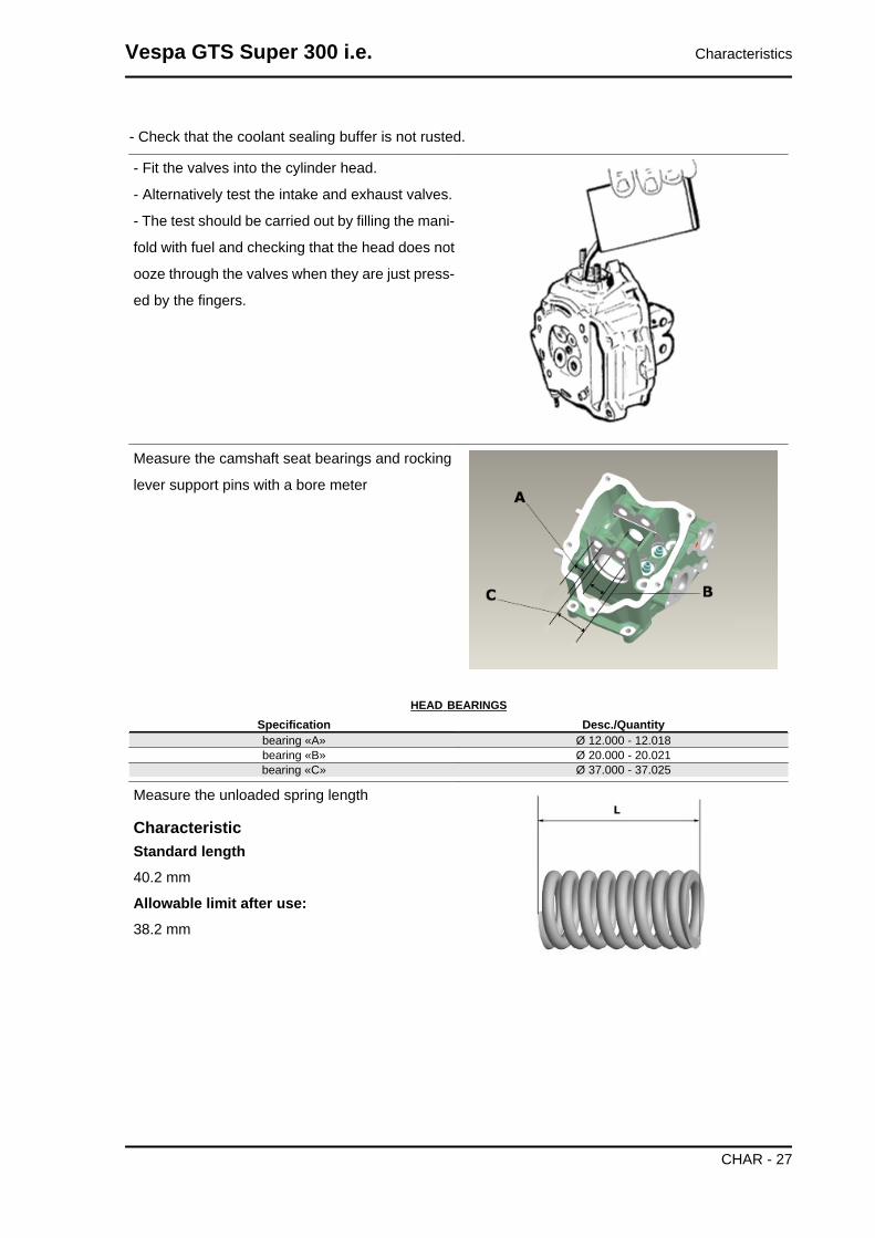
- Check that the coolant sealing buffer is not rusted.
- Fit the valves into the cylinder head.
- Alternatively test the intake and exhaust valves.
- The test should be carried out by filling the mani-
fold with fuel and checking that the head does not
ooze through the valves when they are just press-
ed by the fingers.
Measure the camshaft seat bearings and rocking
lever support pins with a bore meter
HEAD BEARINGSSpecification Desc./Quantitybearing «A» Ø 12.000 - 12.018bearing «B» Ø 20.000 - 20.021bearing «C» Ø 37.000 - 37.025
Measure the unloaded spring length
CharacteristicStandard length40.2 mm
Allowable limit after use:38.2 mm
Vespa GTS Super 300 i.e. Characteristics
CHAR - 27
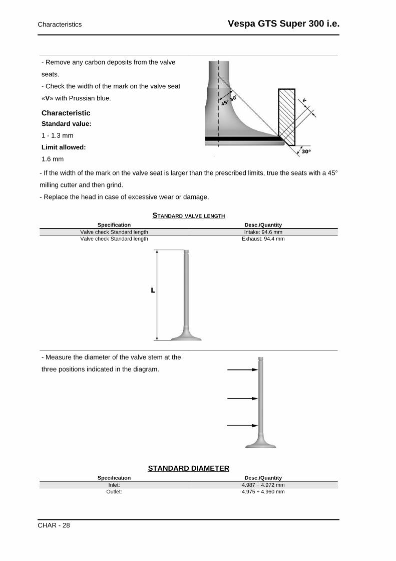
- Remove any carbon deposits from the valve
seats.
- Check the width of the mark on the valve seat
«V» with Prussian blue.
CharacteristicStandard value:1 - 1.3 mm
Limit allowed:1.6 mm
- If the width of the mark on the valve seat is larger than the prescribed limits, true the seats with a 45°
milling cutter and then grind.
- Replace the head in case of excessive wear or damage.
STANDARD VALVE LENGTHSpecification Desc./Quantity
Valve check Standard length Intake: 94.6 mmValve check Standard length Exhaust: 94.4 mm
- Measure the diameter of the valve stem at the
three positions indicated in the diagram.
STANDARD DIAMETERSpecification Desc./Quantity
Inlet: 4.987 ÷ 4.972 mmOutlet: 4.975 ÷ 4.960 mm
Characteristics Vespa GTS Super 300 i.e.
CHAR - 28

MINIMUM DIAMETER ALLOWEDSpecification Desc./Quantity
Inlet: 4.96 mmOutlet: 4.945 mm
- Calculate the clearance between the valve and its guide.
- Check the deviation of the valve stem by resting
it on a «V» shaped support and measuring the ex-
tent of the deformation using a dial gauge.
CharacteristicLimit value allowed:0.1 mm
- Check the concentricity of the valve head by
placing a dial gauge at right angles to the valve
head and rotating it on the «V» shaped support.
CharacteristicLimit allowed:0.03 mm
Measure the valve guides.
CharacteristicValve guide:5+0.012 mm
- After measuring the valve guide diameter and the
valve stem diameter, check the clearance be-
tween guide and stem.
Vespa GTS Super 300 i.e. Characteristics
CHAR - 29

INTAKESpecification Desc./Quantity
Standard clearance: 0.013 ÷ 0.04 mmLimit allowed: 0.08 mm
EXHAUSTSpecification Desc./Quantity
Standard clearance: 0.025 - 0.052 mmLimit allowed: 0.09 mm
- Check that there are no signs of wear on the faying surface with the set screw articulated terminal.
- If no faults are found during the above checks,
the same valves can be reused. For better sealing
results, we recommend grinding the valve seats.
Grind the valves gently with fine-grained lapping
compound. Upon grinding, keep the cylinder head
in horizontal position. This will prevent the lapping
compound residues from penetrating between the
valve stem and the guide (see figure).CAUTION
TO AVOID SCORING THE FAYING SURFACE, DO NOT ROTATE THE VALVE WHEN NO LAPPINGCOMPOUND IS LEFT. CAREFULLY WASH THE CYLINDER HEAD AND THE VALVES WITH ASUITABLE PRODUCT FOR THE TYPE OF LAPPING COMPOUND BEING USED.CAUTION
DO NOT CHANGE THE VALVE FITTING POSITION (RH - LH).
- Check the camshaft bearings for signs of abnormal wear or scores.
- Using a micrometer, measure the camshaft bearings.
STANDARD DIAMETERSpecification Desc./Quantity
Camshaft check: Standard diameter Bearing A Ø: 36.95 to 36.975 mmCamshaft check: Standard diameter Bearing B diameter: 19.959 - 19.98 mm
MINIMUM ADMISSIBLE DIAMETERSpecification Desc./Quantity
Camshaft check: Minimum diameter permitted Bearing A Ø: 36.94 mm
Characteristics Vespa GTS Super 300 i.e.
CHAR - 30

Specification Desc./QuantityCamshaft check: Minimum diameter permitted Bearing B diameter: 19.950 mm
- Using a gauge, measure the height of the cams.
STANDARD HEIGHTSpecification Desc./Quantity
Camshaft check: Standard height Intake: 30.285 mmCamshaft check: Standard height Exhaust: 29.209 mm
Check the axial clearance of the camshaft
CAMSHAFT AXIAL CLEARANCESpecification Desc./Quantity
Camshaft check: Standard axial clearance: 0.11 - 0.41 mmCamshaft check: Maximum admissible axial clearance 0.42 mm
- Check the outside diameter of the rocker pins
- Check there are no signs of wear or scoring on the rocker pins.
- Check the internal diameter of each rocker arm.
Vespa GTS Super 300 i.e. Characteristics
CHAR - 31

- Check there are no signs of wear on the contact pads with the cam and on the jointed adjustment
plate.
ROCKING LEVERS AND PIN DIAMETER:Specification Desc./Quantity
Rocking lever inside diameter: Standard diameter Ø 12.000 - 12.011 mmRocking lever pin diameter: Standard diameter Ø 11.977 - 11.985 mm
Slot packing system
CharacteristicCompression ratio
10.5 - 11.5: 1
Characteristics Vespa GTS Super 300 i.e.
CHAR - 32

Distance "A" to be measured is a value of piston recess, it indicates by how much the piston crown
descends below the plane formed by the cylinder crown. The further the piston enters into the cylinder,
the thinner the base gasket to be used should be (to compensate the compression ratio) and vice versa.N.B.
DISTANCE «A» SHOULD BE MEASURED WITH NO GASKET FITTED BETWEEN THE CRANK-CASE AND THE CYLINDER AND AFTER RESETTING THE DIAL GAUGE, WITH SUPPORT, ON AGROUND PLANE
ENGINE 300 SHIMMINGName Measure A Thickness
shimming 3.70 - 3.60 0.4 ± 0.05shimming 3.60 - 3.40 0.6 ± 0.05shimming 3.40 - 3.30 0.8 ± 0.05
Products
RECOMMENDED PRODUCTS TABLEProduct Description Specifications
AGIP GEAR SAE 80W-90 Lubricant for gearboxes and transmis-sions.
API GL-4
eni i-Ride PG 5W-40 Synthetic based lubricant for high-per-formance four-stroke engines.
JASO MA, MA2 - API SL - ACEA A3
AGIP FILTER OIL Special product for the treatment of foamfilters.
-
AGIP GP 330 Water repellent stringy calcium spraygrease.
R.I.D./A.D.R. 2 10°b) 2 R.I.Na. 2.42 -I.A.T.A. 2 - I.M.D.G. class 2 UN 1950
Page 9022 EM 25-89AGIP BRAKE 4 Brake fluid. SAE J 1703 -FMVSS 116 - DOT 3/4 - ISO
4925 - CUNA NC 956 DOT 4 syntheticfluid
AGIP PERMANENT SPECIAL Ethylene glycol-based antifreeze fluidwith organic inhibition additives. Red,
ready to use.
ASTM D 3306 - ASTM D 4656 - ASTM D4985 - CUNA NC 956-16
AGIP GREASE PV2 Ivory smooth-textured, slightly-stringyanhydrous calcium-base grease.
TL 9150 066, symbol NATO G 460
Vespa GTS Super 300 i.e. Characteristics
CHAR - 33

INDEX OF TOPICS
TOOLING TOOL
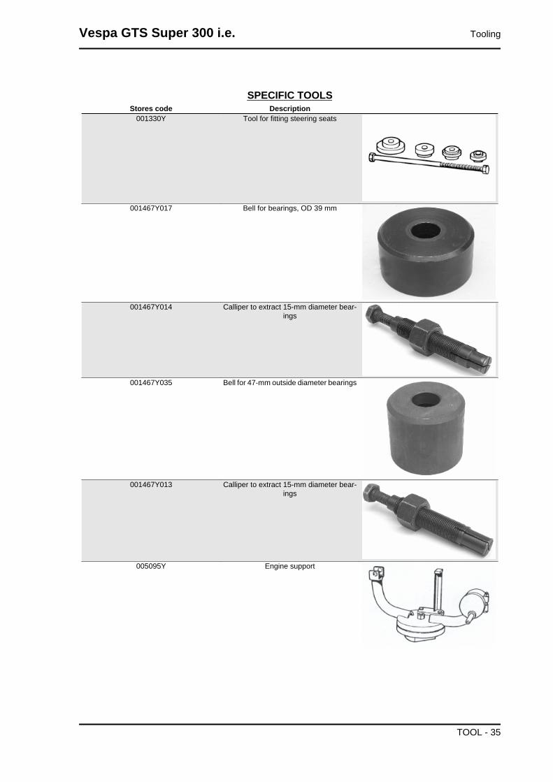
SPECIFIC TOOLSStores code Description
001330Y Tool for fitting steering seats
001467Y017 Bell for bearings, OD 39 mm
001467Y014 Calliper to extract 15-mm diameter bear-ings
001467Y035 Bell for 47-mm outside diameter bearings
001467Y013 Calliper to extract 15-mm diameter bear-ings
005095Y Engine support
Vespa GTS Super 300 i.e. Tooling
TOOL - 35

Stores code Description002465Y Calliper for circlips
006029Y Punch for fitting steering bearing seat onsteering tube
020004Y Punch to remove steering bearings fromheadstock
020021Y Front suspension service tool
020036Y Punch
020038Y Punch
Tooling Vespa GTS Super 300 i.e.
TOOL - 36

Stores code Description020055Y Wrench for steering tube ring nut
020074Y Support base for checking crankshaftalignment
020115Y Ø 18 punch
020150Y Air heater support
020151Y Air heater
020193Y Gauge for oil pressure check
Vespa GTS Super 300 i.e. Tooling
TOOL - 37

Stores code Description020244Y 15-mm diameter punch
020262Y Crankcase splitting strip
020271Y Tool for removing-fitting silent bloc
020263Y Sheath for fitting the driven pulley
020306Y Punch for fitting the valve seal rings
020329Y Vacuum pump Mity-Vac
Tooling Vespa GTS Super 300 i.e.
TOOL - 38

Stores code Description020330Y Stroboscopic light for timing checking
020331Y Digital multimeter
020332Y Digital rpm indicator
020335Y Dial gauge magnetic support
020357Y 32 x 35 mm adaptor
Vespa GTS Super 300 i.e. Tooling
TOOL - 39

Stores code Description020359Y 42 x 47-mm adaptor
020360Y 52 x 55-mm adaptor
020363Y 20 mm guide
020364Y 25-mm Guide
020365Y 22 mm guide
020375Y 28 x 30 mm adaptor
Tooling Vespa GTS Super 300 i.e.
TOOL - 40
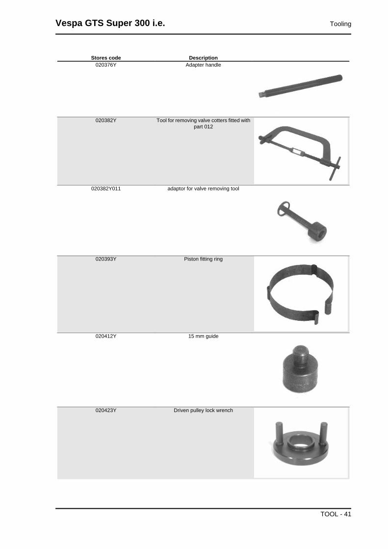
Stores code Description020376Y Adapter handle
020382Y Tool for removing valve cotters fitted withpart 012
020382Y011 adaptor for valve removing tool
020393Y Piston fitting ring
020412Y 15 mm guide
020423Y Driven pulley lock wrench
Vespa GTS Super 300 i.e. Tooling
TOOL - 41

Stores code Description020424Y Punch for fitting driven pulley roller casing
020426Y Piston fitting fork
020428Y Support to check piston position
020431Y Valve oil seal extractor
020434Y Fitting for oil pressure check
Tooling Vespa GTS Super 300 i.e.
TOOL - 42
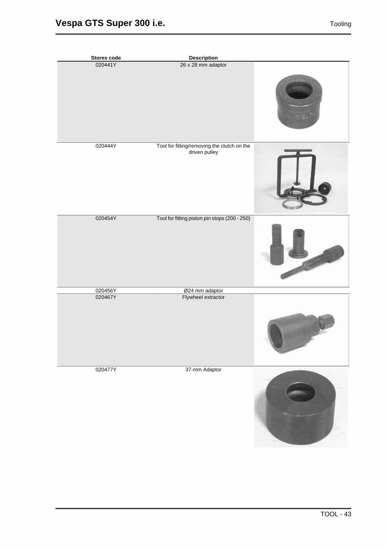
Stores code Description020441Y 26 x 28 mm adaptor
020444Y Tool for fitting/removing the clutch on thedriven pulley
020454Y Tool for fitting piston pin stops (200 - 250)
020456Y Ø24 mm adaptor020467Y Flywheel extractor
020477Y 37-mm Adaptor
Vespa GTS Super 300 i.e. Tooling
TOOL - 43

Stores code Description020480Y Fuel pressure check set
020483Y 30 mm guide
020489Y Hub cover support stud bolt kit
020621Y HV cable extraction adaptor
020622Y Transmission-side oil seal punch
020626Y Driving pulley lock wrench
Tooling Vespa GTS Super 300 i.e.
TOOL - 44

Stores code Description020627Y Flywheel lock wrench
020648Y Single battery charger
020334Y Multiple battery charger
020922Y Diagnosis Tool
Vespa GTS Super 300 i.e. Tooling
TOOL - 45

INDEX OF TOPICS
MAINTENANCE MAIN

Maintenance chart
SCHEDULED MAINTENANCE TABLEI: CHECK AND CLEAN, ADJUST, LUBRICATE OR REPLACE IF NECESSARY.C: CLEAN, R: REPLACE, A: ADJUST, L: LUBRICATE* Replace every 2 years
Km x 1,000 1 5 10 15 20 25 30 35 40 45 50 55 60Safety fasteners I I I I ISpark plug R R R R R RDrive belt R R R RThrottle control A A A A A A AAir filter C C C C C CBelt compartment air filter I I I I I IOil filter R R R R R R RValve clearance A A AElectrical system and battery I I I I I I IBrake fluid * I I I I I I ICoolant * I I I I I I IEngine oil R I R I R I R I R I R I RHub oil R I R I R I RBrake pads I I I I I I I I I I I I ISliding shoes / CVT rollers R R R R R RTyre pressure and wear I I I I I I IVehicle road test I I I I I I ISuspension I I I I I ISteering A A A A A A A
MAINTENANCE TABLE - TIMEKm x 1000 1 5 10 15 20 25 30 35 40 45 50 55 60
Operation Time 60' 10' 100' 45' 150' 10' 140' 10' 150' 45' 100' 10' 190'
Checking the spark advance
The ignition advance is determined electronically
on the basis of parameters known by the control
unit. For this reason it is not possible to interpret
the reference values based on the engine rpm.
The ignition advance value is detectable at any
time using the diagnostic tester. It is possible to
check whether the ignition advance determined by
the injection system matches the value actually
activated on the engine, by means of the strobo-
scopic light.
Proceed as follows:
- Remove the spark plug.
- Remove the plastic cover on the flywheel cover
shown in the picture.
Vespa GTS Super 300 i.e. Maintenance
MAIN - 47

- Remove the transmission compartment air intake
cover shown in the picture.
- Rotate the driving pulley fan using a screwdriver
until the reference marks between the flywheel
and flywheel cover coincide as shown in the pic-
ture.
- Bring the reference mark onto the transmission
side between the fan and the transmission cover
as shown in the picture.
- Refit the spark plug.
- Refit the plastic cap on the flywheel cover.
- Adjust the spark gap to the contact position (no
reference mark visible) and install it on the engine
between the spark plug and spark plug cap
- Connect the induction clamp on the spark gap
cable respecting the proper polarity (the arrow on
the clamp must be pointing at the spark plug).
- Connect the diagnostic tester.
- Start the engine.
- Select the «Parameters» function in this menu.
- Set the stroboscopic light control to the traditional
four-stroke engine position (1 spark, 2 revs).
- Check that the real values of rpm and ignition
advance match those measured using the diag-
nostic tester.
If the values do not correspond, check:
- distribution timing
- engine speed sensor
- injection control unit
Specific tooling020922Y Diagnosis Tool
020330Y Stroboscopic light for timing check-ing
020621Y HV cable extraction adaptor
Maintenance Vespa GTS Super 300 i.e.
MAIN - 48

Spark plug
- Rest the scooter on its stand
- Open the saddle and take out the helmet com-
partment
- Disconnect the spark plug HV wire cap;
- Unscrew the spark plug using the wrench sup-
plied;
- Check the conditions of the spark plug, make
sure the insulation is intact, that the electrodes are
not excessively worn or sooty, the conditions of the
washer, and measure the distance between the
electrodes using the appropriate feeler thickness
gauge.
-Adjust the distance, if necessary, by bending the
side electrode very carefully. In case of anomaly
(as described before), replace the spark plug with
another of the recommended type;
- Fit the spark plug with the correct inclination and
manually screw it all the way down, then use the
special spanner to tighten it.
- Insert the cap onto the spark plug and proceed
with the reassembly operations.CAUTIONTHE SPARK PLUG MUST BE REMOVED WHEN THE MO-TOR IS COLD.THE SPARK PLUG MUST BE REPLACEDEVERY 20,000 KM. THE USE OF NON CONFORMINGELECTRONIC IGNITION CONTROL UNITS OR SPARKPLUGS OTHER THAN THOSE PRESCRIBED CAN SERI-OUSLY DAMAGE THE ENGINE.
CharacteristicElectrode gap
Vespa GTS Super 300 i.e. Maintenance
MAIN - 49

0.7 to 0.8 mm
Electric characteristicSpark plugNGK CR8EKB
Locking torques (N*m)Spark plug 12 - 14
Hub oil
Check
-Place the vehicle on the centre stand on flat
ground;
- Remove the oil dipstick «A», dry it with a clean
cloth and put it back into its hole tightening it
completely;
Remove the dipstick and check that the oil level is
slightly over the second notch starting from the
lower end; if the level is under the MAX. mark, it
needs to be filled with the right amount of hub oil.
-Screw up the oil dipstick again and make sure it
is locked properly into place.
Replacement
-Remove the oil filler cap «A».
- Unscrew the oil drainage cap «B» and drain out
all the oil.
- Screw in the drainage cap again and fill the hub
with the prescribed oil.
Recommended productsAGIP GEAR SAE 80W-90 Lubricant for gear-boxes and transmissions.API GL-4
CharacteristicRear hub oilCapacity approximately 250 cc
Maintenance Vespa GTS Super 300 i.e.
MAIN - 50
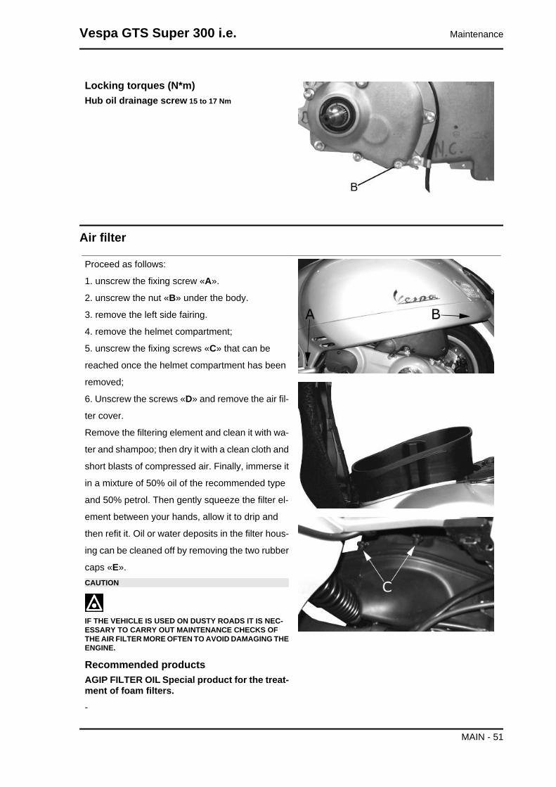
Locking torques (N*m)Hub oil drainage screw 15 to 17 Nm
Air filter
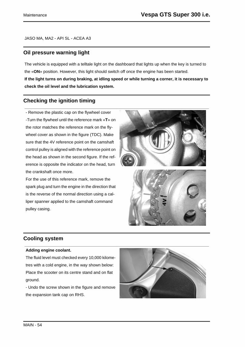
Proceed as follows:
1. unscrew the fixing screw «A».
2. unscrew the nut «B» under the body.
3. remove the left side fairing.
4. remove the helmet compartment;
5. unscrew the fixing screws «C» that can be
reached once the helmet compartment has been
removed;
6. Unscrew the screws «D» and remove the air fil-
ter cover.
Remove the filtering element and clean it with wa-
ter and shampoo; then dry it with a clean cloth and
short blasts of compressed air. Finally, immerse it
in a mixture of 50% oil of the recommended type
and 50% petrol. Then gently squeeze the filter el-
ement between your hands, allow it to drip and
then refit it. Oil or water deposits in the filter hous-
ing can be cleaned off by removing the two rubber
caps «E».CAUTION
IF THE VEHICLE IS USED ON DUSTY ROADS IT IS NEC-ESSARY TO CARRY OUT MAINTENANCE CHECKS OFTHE AIR FILTER MORE OFTEN TO AVOID DAMAGING THEENGINE.
Recommended productsAGIP FILTER OIL Special product for the treat-ment of foam filters.-
Vespa GTS Super 300 i.e. Maintenance
MAIN - 51

Engine oil
In four stroke engines, the engine oil is used to lubricate the timing elements, the bench bearings and
the thermal group. An insufficient quantity of oil can cause serious damage to the engine.
In all four stroke engines, the deterioration of the oil characteristics, or a certain consumption should
be considered normal, especially if during the run-in period. Consumption levels in particular can be
influenced by the conditions of use (e.g.: oil consumption increases when driving at "full throttle".
Replacement
At 1,000 km and after every 10,000 km, the oil and
the filter must be changed. The engine must be
drained by running off the oil from drainage cap
"B" of the flywheel side gauze pre-filter; further-
more to facilitate oil drainage, loosen the cap/
dipstick "A". Once all the oil has drained through
the drainage hole, unscrew the oil cartridge filter
"C" and remove it.
Make sure the pre-filter and drainage plug O-rings
are in good conditions.
Lubricate them and refit the mesh filter and the oil
drainage plug, screwing them up to the prescribed
torque.
Refit the new cartridge filter being careful to lubri-
cate the O-ring before fitting it.
Change the engine oil.
Since a certain quantity of oil still remains in the
circuit, oil must be filled from cap "A". Then start
up the scooter, leave it running for a few minutes
and switch it off: after five minutes check the level
Maintenance Vespa GTS Super 300 i.e.
MAIN - 52

and if necessary top up without exceeding the
MAX level. The cartridge filter must be replaced
every time the oil is changed. Use new oil of the
recommended type for topping up and changing
purposes.N.B.THE ENGINE MUST BE HOT WHEN THE OIL IS CHANGED.
Recommended productseni i-Ride PG 5W-40 Synthetic based lubricantfor high-performance four-stroke engines.JASO MA, MA2 - API SL - ACEA A3
Check
This operation must be carried out with the engine cold and following the procedure below:
1. Place the vehicle on its centre stand and on flat ground.
2. Undo cap/dipstick "A", dry it off with a clean cloth and replace it, screwing down completely.
3. Remove the cap/dipstick again and check that the level is between the min and max. marks; top-
up, if required.
The MAX level mark indicates a quantity of around 1300 cc of engine oil. If the check is carried out after
the vehicle has been used, and therefore with a hot engine, the level will be lower; in order to carry out
a correct check, wait at least 10 minutes after the engine has been stopped so as to get the correct
level.
Engine oil top-up
The oil should be topped up after having checked
the level and in any case by adding oil without
ever exceeding the MAX. level.
Restoration of the level from MIN to MAX requires
approximately 200 cc.
Engine oil filter
Change oil and replace filter as indicated in the scheduled maintenance table. Use new oil of the rec-
ommended type for topping up and changing purposes.
Make sure the pre-filter and drainage plug O-rings are in good conditions. Lubricate them and refit the
mesh filter and the oil drainage plug, screwing them up to the prescribed torque. Refit the new cartridge
filter being careful to lubricate the O-ring before fitting it. Change the engine oil.
Recommended productseni i-Ride PG 5W-40 Synthetic based lubricant for high-performance four-stroke engines.
Vespa GTS Super 300 i.e. Maintenance
MAIN - 53
JASO MA, MA2 - API SL - ACEA A3
Oil pressure warning light
The vehicle is equipped with a telltale light on the dashboard that lights up when the key is turned to
the «ON» position. However, this light should switch off once the engine has been started.
If the light turns on during braking, at idling speed or while turning a corner, it is necessary to
check the oil level and the lubrication system.
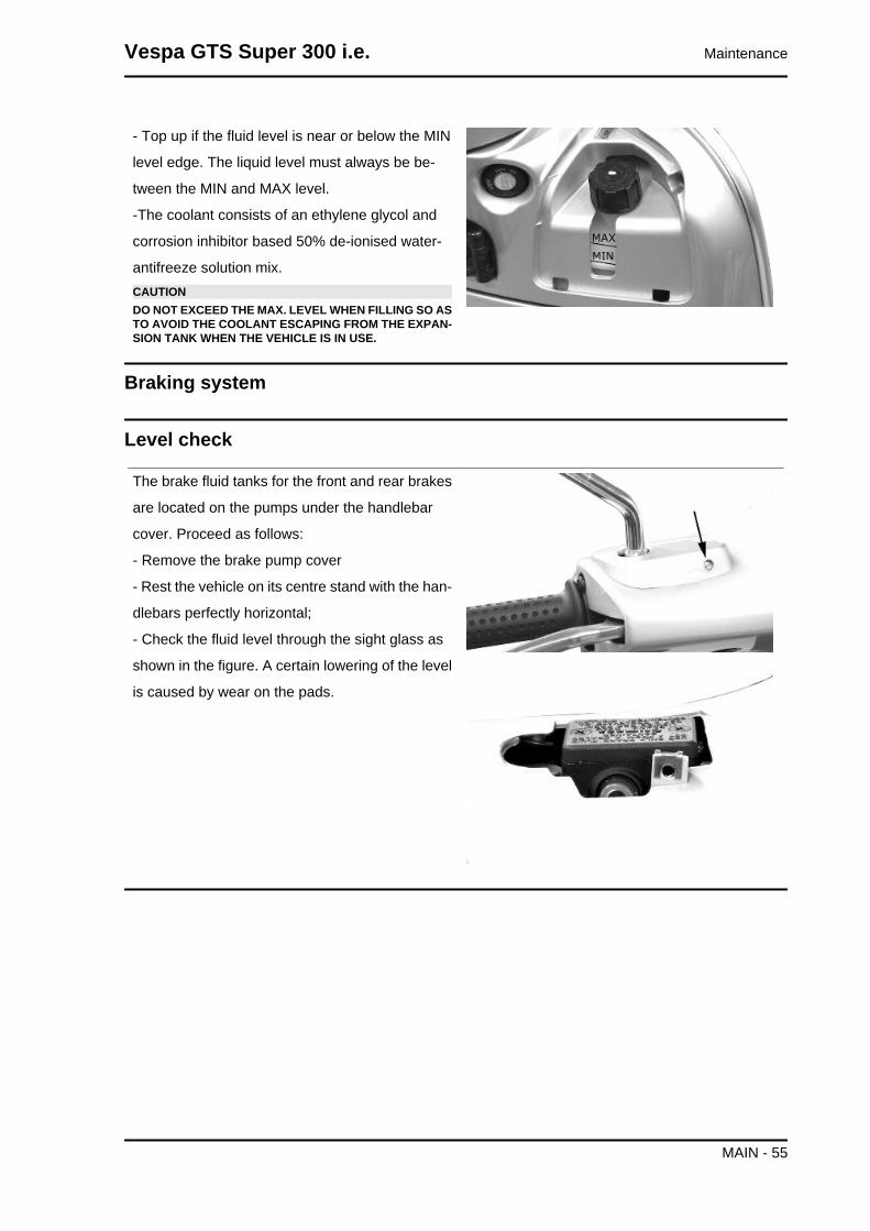
Checking the ignition timing
- Remove the plastic cap on the flywheel cover
-Turn the flywheel until the reference mark «T» on
the rotor matches the reference mark on the fly-
wheel cover as shown in the figure (TDC). Make
sure that the 4V reference point on the camshaft
control pulley is aligned with the reference point on
the head as shown in the second figure. If the ref-
erence is opposite the indicator on the head, turn
the crankshaft once more.
For the use of this reference mark, remove the
spark plug and turn the engine in the direction that
is the reverse of the normal direction using a cal-
liper spanner applied to the camshaft command
pulley casing.
Cooling system
Adding engine coolant.
The fluid level must checked every 10,000 kilome-
tres with a cold engine, in the way shown below:
Place the scooter on its centre stand and on flat
ground.
- Undo the screw shown in the figure and remove
the expansion tank cap on RHS.
Maintenance Vespa GTS Super 300 i.e.
MAIN - 54
- Top up if the fluid level is near or below the MIN
level edge. The liquid level must always be be-
tween the MIN and MAX level.
-The coolant consists of an ethylene glycol and
corrosion inhibitor based 50% de-ionised water-
antifreeze solution mix.CAUTIONDO NOT EXCEED THE MAX. LEVEL WHEN FILLING SO ASTO AVOID THE COOLANT ESCAPING FROM THE EXPAN-SION TANK WHEN THE VEHICLE IS IN USE.
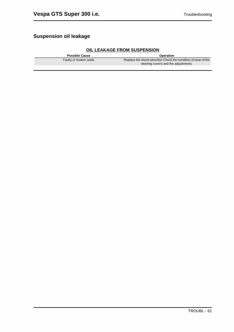
Braking system
Level check
The brake fluid tanks for the front and rear brakes
are located on the pumps under the handlebar
cover. Proceed as follows:
- Remove the brake pump cover
- Rest the vehicle on its centre stand with the han-
dlebars perfectly horizontal;
- Check the fluid level through the sight glass as
shown in the figure. A certain lowering of the level
is caused by wear on the pads.
Vespa GTS Super 300 i.e. Maintenance
MAIN - 55

Top-up
- Position the vehicle on a flat surface and on the
centre stand
- Remove the brake pump cover as indicated in the
photo
Check the brake fluid level through the sight glass
on the pump as shown in the photograph
- If the level is below the minimum, fill using the two
screws shown in the figure
- Remove the gasket and fill with DOT 4 until the spyglass is completely covered
For refitting purposes carry out the operations in
the reverse order from the removal operation and
respect the tightening torque of the tank cover
screws.CAUTION
MAKE SURE THE BRAKE FLUID DOES NOT GET INTOYOUR EYES OR ON YOUR SKIN OR CLOTHES. IF THISHAPPENS ACCIDENTALLY, WASH WITH WATER.CAUTION
THE BRAKING CIRCUIT FLUID IS HIGHLY CORROSIVE.THEREFORE, WHEN TOPPING UP, AVOID LETTING ITCOME INTO CONTACT WITH THE PAINTED PARTS OFTHE VEHICLE. THE BRAKING CIRCUIT FLUID IS HYGRO-SCOPIC, THAT IS, IT ABSORBS HUMIDITY FROM THESURROUNDING AIR. IF THE HUMIDITY IN THE BRAKINGFLUID EXCEEDS A CERTAIN VALUE, IT WILL LEAD TOINEFFICIENT BRAKING.CAUTIONNEVER USE BRAKE FLUID COMING FROM OPEN OR PAR-TIALLY USED CONTAINERS. UNDER NORMAL CLIMATICCONDITIONS, BRAKE FLUID MUST BE CHANGED EVERY20,000 KM OR ANYWAY EVERY 2 YEARS.
Locking torques (N*m)Brake pump reservoir screws 15 to 20
Maintenance Vespa GTS Super 300 i.e.
MAIN - 56

Headlight adjustment
Proceed as follows:
1. Position the vehicle in running order and with
the tyres inflated to the prescribed pressure, onto
a flat surface 10 m away from a half-lit white
screen; ensure that the longitudinal axis of the ve-
hicle is perpendicular to the screen;
2. Turn on the headlight and check that the boun-
dary of the light beam projected onto the screen is
not higher than 9/10 or lower than 7/10 of the dis-
tance between the centre of the headlight and the
ground;
3. Otherwise, adjust the right headlight with screw
«A».N.B.THE ABOVE PROCEDURE COMPLIES WITH THE EURO-PEAN STANDARDS REGARDING MAXIMUM AND MINI-MUM HEIGHT OF LIGHT BEAMS. REFER TO THE STATU-TORY REGULATIONS IN FORCE IN EVERY COUNTRYWHERE THE VEHICLE IS USED.
Vespa GTS Super 300 i.e. Maintenance
MAIN - 57

INDEX OF TOPICS
TROUBLESHOOTING TROUBL

This section makes it possible to find what solutions to apply when troubleshooting.
For each failure, a list of the possible causes and pertaining operations is given.
Engine
Excessive oil consumption/Exhaust smoke
EXCESSIVE CONSUMPTIONPossible Cause Operation
Wrong valve adjustment Adjust the valve clearance properlyOverheated valves Remove the head and the valves, grind or replace the valves
Misshapen/worn valve seats Replace the head unitWorn cylinder, Worn or broken piston rings Replace the piston cylinder assembly or piston rings
Worn or broken piston rings or piston rings that have not beenfitted properly
Replace the piston cylinder unit or just the piston rings
Oil leaks from the couplings or from the gaskets Check and replace the gaskets or restore the coupling sealWorn valve oil seal Replace the valve oil sealWorn valve guides Check and replace the head unit if required
Insufficient lubrication pressure
LOW LUBRICATION PRESSUREPossible Cause Operation
By-Pass remains open Check the By-Pass and replace if required. Carefully clean theBy-Pass area.
Oil pump with excessive clearance Perform the dimensional checks on the oil pump componentsOil filter too dirty Replace the cartridge filterOil level too low Restore the level adding the recommended oil type
Transmission and brakes
Clutch grabbing or performing inadequately
IRREGULAR CLUTCH PERFORMANCE OR SLIPPAGEPossible Cause Operation
Faulty clutch Check that there is no grease on the masses. Check that theclutch mass faying surface with the bell is mainly in the centrewith equivalent characteristics on the three masses. Check thatthe clutch housing is not scored or worn in an anomalous way
Insufficient braking
INEFFICIENT BRAKING SYSTEMPossible Cause Operation
Inefficient braking system Check the pad wear (1.5 min). Check that the brake discs arenot worn, scored or warped. Check the correct level of fluid inthe pumps and replace brake fluid if necessary. Check there isno air in the circuits; if necessary, bleed the air. Check that the
front brake calliper moves in axis with the disc.Fluid leakage in hydraulic braking system Failing elastic fittings, plunger or brake pump seals, replace
Vespa GTS Super 300 i.e. Troubleshooting
TROUBL - 59

Possible Cause OperationBrake disc slack or distorted Check the brake disc screws are locked; measure the axial shift
of the disc with a dial gauge and with wheel mounted on thevehicle.
Brakes overheating
BRAKE OVERHEATPossible Cause Operation
Defective plunger sliding Check calliper and replace any damaged part.Brake disc slack or distorted Check the brake disc screws are locked; use a dial gauge and
a wheel mounted on the vehicle to measure the axial shift ofthe disc.
Clogged compensation holes on the pump Clean carefully and blast with compressed air.Swollen or stuck rubber gaskets Replace gaskets.
Steering and suspensions
Heavy steering
STEERING HARDENINGPossible Cause Operation
Steering hardening Check the tightening of the top and bottom ring nuts. If irregu-larities continue in turning the steering even after making theabove adjustments, check the seats in which the ball bearingsrotate: replace them if they are recessed or if the balls are flat-
tened.
Excessive steering play
EXCESSIVE STEERING CLEARANCEPossible Cause Operation
Torque not conforming Check the tightening of the top and bottom ring nuts. If irregu-larities continue in turning the steering even after making theabove adjustments, check the seats in which the ball bearingsrotate: replace them if they are recessed or if the balls are flat-
tened.
Noisy suspension
NOISY SUSPENSIONPossible Cause Operation
Faults in the suspension system If the front suspension is noisy, check: the efficiency of the frontshock absorber; the condition of the ball bearings and relevantlock-nuts, the limit switch rubber buffers; and the movementbushings. In conclusion, check the tightening torque of the
wheel hub, the brake calliper, the shock absorber disc in theattachment to the hub and the steering tube.
Troubleshooting Vespa GTS Super 300 i.e.
TROUBL - 60
Suspension oil leakage
OIL LEAKAGE FROM SUSPENSIONPossible Cause Operation
Faulty or broken seals Replace the shock absorber Check the condition of wear of thesteering covers and the adjustments.
Vespa GTS Super 300 i.e. Troubleshooting
TROUBL - 61
INDEX OF TOPICS
ELECTRICAL SYSTEM ELE SYS

KEY
1. 12v-10Ah battery
2. Starter relay
3. Starter motor
4. Starter button
5. Voltage regulator
6. Magneto flywheel
7. Fuse No. 1 - 30A
8. Fuse No. 5 - 7.5A
9. Fuse No. 2 - 15A
10. Fuses No. 6 - 7.5A
11. Fuse No. 3 - 15A
12. Fuse No. 4 - 7.5A
13. Fuse No. 7 - 7.5A
14. Key switch contacts
15. Engine stop switch
16. N.2 stop buttons
17. Brake lamp 12v-16w
18. Injection load relay
19. Electric fan remote control
Vespa GTS Super 300 i.e. Electrical system
ELE SYS - 63

20. Radiator electric fan
21. Horn button
22. Horn
23. Lambda probe
24. Engine speed sensor
25. H.V. coil.
26. Fuel injector
27. Engine temperature sensor
28. Fuel pump
29. Diagnosis socket
30. Injection electronic control unit
31. Immobilizer antenna
32. Fuel level transmitter
33. Oil pressure sensor
34. Instrument panel
35. Light switch
36. Headlight relay
37. Saddle opening switch
38. Saddle opening actuator
39. Headlight with dual light bulb 12v-55w/60w
40. Turn indicator control device
41. Turn indicator switch
42. No. 4 bulbs for turn indicators 12v-6w*
43. Pre-installation for anti-theft device
44. No. 2 Front LED daylight running light bulb
45. No.1 rear daylight running light bulb 12v-5w
46. No. 1 license plate bulb 12v-5w
* for USA market 12V-10W bulbs are used
Key
Ar: Orange Az: Light Blue Bi: White Bl: Blue Gi: Yellow Gr:Grey
Ma:Brown Ne: Black Ro: Pink Rs: Red Ve: Green Vi: Purple
Electrical system Vespa GTS Super 300 i.e.
ELE SYS - 64

Components arrangement
6. ABS control unit
- Remove the leg shield back plate to reach it.
9. Immobilizer aerial- Remove the shield back
plate to reach it.
Vespa GTS Super 300 i.e. Electrical system
ELE SYS - 65

10. Injection ECU - Remove the helmet compart-
ment to reach it.
11. Diagnosis connector - Remove the helmet
compartment to reach it.
15. H.V. coil- Remove the battery to reach it; to
remove the coil, first remove the footrest and undo
the two screws indicated.
Electrical system Vespa GTS Super 300 i.e.
ELE SYS - 66

18-30-38 Horn - Remote control switches Re-
move front central cover to reach it.
20-23. Remote control switches - Remove the
front central cover and the helmet compartment to
reach them.
26. Main fuses - Open the front top box to reach
them.
Vespa GTS Super 300 i.e. Electrical system
ELE SYS - 67

27. Voltage regulator - Remove the shield back
plate to reach it.
28. Magneto flywheel - Remove the flywheel cov-
er, as described in the «Engine» chapter, to reach
it. To get access to the connectors, remove the
helmet compartment.
40. Key switch contacts - Remove the shield
back plate to reach them.
33. Saddle-opening actuator - Remove the hel-
met compartment to reach it, undo the two screws
indicated and remove the fixing bracket together
with the actuator.
Electrical system Vespa GTS Super 300 i.e.
ELE SYS - 68

8. Fuel level transmitter - Remove the fuel tank
to reach it.
7. Oil pressure sensor - Remove the right side
fairing to reach it.
22. Battery - Remove the rear central cover to
reach it.
Ground points
On the vehicle there is a ground point on the chassis marked with the letter "A"
Vespa GTS Super 300 i.e. Electrical system
ELE SYS - 69

There is another ground point "B" on the starter motor.
Electrical system installation
Conceptual diagrams
Electrical system Vespa GTS Super 300 i.e.
ELE SYS - 70

Ignition
KEY
1. 12v-10Ah battery
7. Fuse No. 1 - 30A
8. Fuse No. 5 - 7.5A
9. Fuse No. 2 - 15A
10. Fuses No. 6 - 7.5A
11. Fuse No. 3 - 15A
12. Fuse No. 4 - 7.5A
14. Key switch contacts
15. Engine stop switch
18. Injection load relay
25. H.V. coil.
29. Diagnosis socket
30. Injection electronic control unit
31. Immobilizer antenna
34. Instrument panel
Vespa GTS Super 300 i.e. Electrical system
ELE SYS - 71

Battery recharge and starting
KEY
1. 12v-10Ah battery
2. Starter relay
3. Starter motor
4. Starter button
5. Voltage regulator
6. Magneto flywheel
7. Fuse No. 1 - 30A
8. Fuse No. 5 - 7.5A
9. Fuse No. 2 - 15A
10. Fuses No. 6 - 7.5A
14. Key switch contacts
16. N.2 stop buttons
17. Brake lamp 12v-16w
30. Injection electronic control unit
Electrical system Vespa GTS Super 300 i.e.
ELE SYS - 72

Level indicators and enable signals section
KEY
1. 12v-10Ah battery
7. Fuse No. 1 - 30A
8. Fuse No. 5 - 7.5A
9. Fuse No. 2 - 15A
10. Fuses No. 6 - 7.5A
14. Key switch contacts
15. Engine stop switch
23. Lambda probe
24. Engine speed sensor
27. Engine temperature sensor
30. Injection electronic control unit
31. Immobilizer antenna
32. Fuel level transmitter
33. Oil pressure sensor
34. Instrument panel
Vespa GTS Super 300 i.e. Electrical system
ELE SYS - 73

ABS
1. ABS control unit
2. Tone wheel sensors
3. Instrument panel
4. Engine control unit
Electrical system Vespa GTS Super 300 i.e.
ELE SYS - 74

Devices and accessories
KEY
1. 12v-10Ah battery
7. Fuse No. 1 - 30A
8. Fuse No. 5 - 7.5A
9. Fuse No. 2 - 15A
10. Fuses No. 6 - 7.5A
11. Fuse No. 3 - 15A
12. Fuse No. 4 - 7.5A
14. Key switch contacts
19. Electric fan remote control
20. Radiator electric fan
21. Horn button
22. Horn
30. Injection electronic control unit
34. Instrument panel
37. Saddle opening switch
38. Saddle opening actuator
40. Turn indicator control device
Vespa GTS Super 300 i.e. Electrical system
ELE SYS - 75

41. Turn indicator switch
43. Pre-installation for anti-theft device
Lights and turn indicators
key:
1. 12v-10Ah battery
7. Fuse No. 1 - 30A
8. Fuse No. 5 - 7.5A
9. Fuse No. 2 - 15A
10. Fuses No. 6 - 7.5A
11. Fuse No. 3 - 15A
12. Fuse No. 4 - 7.5A
13. Fuse No. 7 - 7.5A
14. Key switch contacts
30. Injection electronic control unit
34. Instrument panel
35. Light switch
36. Headlight relay
39. Headlight with dual light bulb 12v-55w/60w
40. Turn indicator control device
Electrical system Vespa GTS Super 300 i.e.
ELE SYS - 76
41. Turn indicator switch
42. No. 4 bulbs for turn indicators 12v-6w
44. No. 2 Front LED daylight running light
45. No.1 rear daylight running light bulb 12v-5w
46. No. 1 license plate bulb 12v-5w
* for USA market 12V-10W bulbs are used
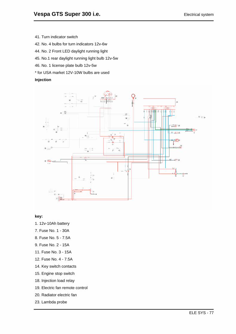
Injection
key:
1. 12v-10Ah battery
7. Fuse No. 1 - 30A
8. Fuse No. 5 - 7.5A
9. Fuse No. 2 - 15A
11. Fuse No. 3 - 15A
12. Fuse No. 4 - 7.5A
14. Key switch contacts
15. Engine stop switch
18. Injection load relay
19. Electric fan remote control
20. Radiator electric fan
23. Lambda probe
Vespa GTS Super 300 i.e. Electrical system
ELE SYS - 77

24. Engine speed sensor
25. H.V. coil.
26. Fuel injector
27. Engine temperature sensor
28. Fuel pump
30. Injection electronic control unit
31. Immobilizer antenna
34. Instrument panel
Checks and inspections
This section is dedicated to the checks on the electrical system components.
Immobiliser
The electronic ignition system is controlled by the
control unit with the integrated Immobilizer sys-
tem. The immobiliser is an antitheft system which
allows the vehicle to function only if it is activated
by means of the coded keys that the control unit
recognises. The code is integrated in a transpond-
er in the key block. This allows the driver clear
operation without having to do anything other than
just turning the key. The Immobilizer system con-
sists of the following components:
- Control unit
- Immobilizer aerial
- master and service keys with built-in transponder
- HV coil.
- diagnosis LED
The diagnosis LED also works as a theft-deterrent
blinker. This function is activated every time the
ignition switch is turned to the "OFF" position, or
the emergency stop switch is turned to the "OFF"
position. It remains activated for 48 hours in order
not to affect the battery charge.
When the ignition switch is turned to "ON", it inter-
rupts the function of the immobiliser lamp and a
start enable lamp comes "ON".
Electrical system Vespa GTS Super 300 i.e.
ELE SYS - 78

The duration of the flash depends on the program-
ming of the electronic control unit.
If the LED is off regardless of the position of the
ignition switch and/or the instrument panel is not
initiated, check if:
• there is battery voltage
• that fuse 1 and fuse 5 are in good con-
ditions.
• there is power to the control unit as
specified below:
Remove the connector mounting bracket shown in
the photograph and disconnect the connector from
the control unit. Check the following conditions:
With the key switch set to OFF:
• there is battery voltage between terminals 7-9 and terminal 9-chassis ground (fixed power supply). If
there is no voltage check that fuse 2 and its cable are in working order.
With the key switch in the ON position:
• there is battery voltage between terminals 6-7 and terminal 6-chassis ground (fixed power supply). If
there is no voltage, check the key switch contacts, that fuse 5 and its cable are in working order.
• There is continuity between terminals 4-19 and 4-33 with the emergency cut-out switch in
the RUN position. If there is no continuity, check the contacts of the latter.
If no faults are found, replace the control unit.
After removing the leg shield back plate, remove
the electrical connection from the aerial as shown
in the picture.
Vespa GTS Super 300 i.e. Electrical system
ELE SYS - 79

Remove the protective base from the connector.
With the ignition switch at ON check there is bat-
tery voltage between the Red-White and Black
cables
Virgin circuit
When the ignition system is not encrypted, any key
will start the engine but limited to 2000 rpm. The
keys can only be recognised if the control unit has
been programmed properly.
The data storage procedure for a previously un-
programmed control unit provides for the recogni-
tion of the red key (master key) as the first key to
be stored to memory: this becomes particularly
important because it is the only key that enables
the control unit to be wiped clean and reprogram-
med for the memorisation of the service keys.
The master and service keys must be used to code
the system as follows:
- Insert the Master key, turn it to «ON» and keep
this position for two seconds (lower and upper lim-
its 1 to 3 seconds).
- Insert the blue key and set to «ON» for 2 seconds.
- If you have copies of the key, repeat the operation
with each key.
Electrical system Vespa GTS Super 300 i.e.
ELE SYS - 80

- Insert the MASTER key again and turn it to «ON»
for 2 seconds.
The maximum time to change keys is 10 seconds.
A maximum of 7 service keys (blue) can be pro-
grammed at one time.
It is essential to adhere to the times and the pro-
cedure. If you do not, start again from the begin-
ning.
Once the system has been programmed, master
key transponder, decoder and control unit are
strictly matched.
With this link established, it is now possible to en-
code new service keys, in the event of losses,
replacements, etc.
Each new programming deletes the previous one
so, in order to add or eliminate keys, you must re-
peat the procedure using all the keys you intend to
keep using.
If a service key becomes uncoded, the efficiency
of the high voltage circuit shielding must be thor-
oughly inspected. In any case it is advisable to use
resistive spark plugs.
CharacteristicShielded cap resistance~ 5000 Ω.
Diagnostic codes
The Immobilizer system is tested each time the ig-
nition key is turned from «OFF» to «ON». During
this diagnosis phase a number of control unit sta-
tuses can be identified and various light codes
displayed. Regardless of the code transmitted, if
at the end of the diagnosis the LED remains off
permanently, the ignition is enabled. If, however,
the LED remains on permanently, it means the ig-
nition is inhibited:
Vespa GTS Super 300 i.e. Electrical system
ELE SYS - 81
1. Previously unused control unit - key inser-
ted: a single 2 second flash is displayed, after
which the LED remains off permanently. The keys
can be stored to memory, the vehicle can be star-
ted but with a limitation imposed on the number of
revs.
2. Previously unused control unit - transpond-
er absent or cannot be used: the LED is on
permanently. In this condition no operations are
possible including the start up of the vehicle.
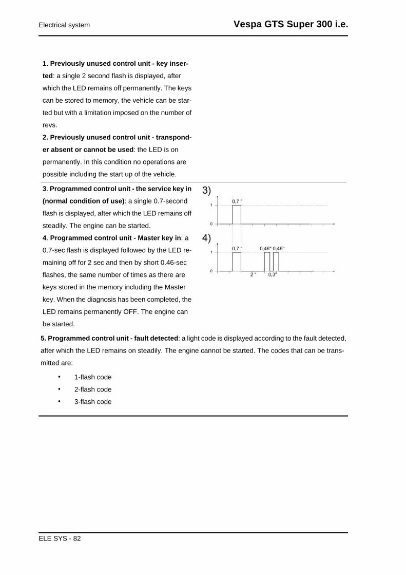
3. Programmed control unit - the service key in
(normal condition of use): a single 0.7-second
flash is displayed, after which the LED remains off
steadily. The engine can be started.
4. Programmed control unit - Master key in: a
0.7-sec flash is displayed followed by the LED re-
maining off for 2 sec and then by short 0.46-sec
flashes, the same number of times as there are
keys stored in the memory including the Master
key. When the diagnosis has been completed, the
LED remains permanently OFF. The engine can
be started.
5. Programmed control unit - fault detected: a light code is displayed according to the fault detected,
after which the LED remains on steadily. The engine cannot be started. The codes that can be trans-
mitted are:
• 1-flash code
• 2-flash code
• 3-flash code
Electrical system Vespa GTS Super 300 i.e.
ELE SYS - 82
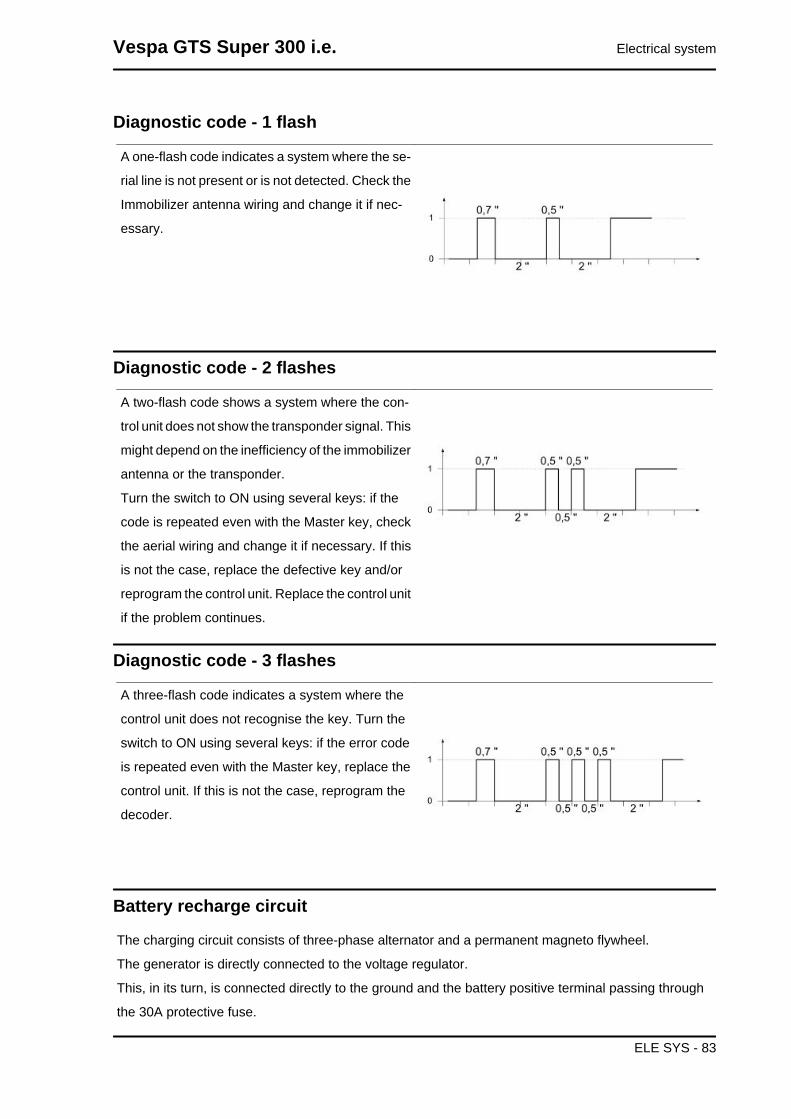
Diagnostic code - 1 flash
A one-flash code indicates a system where the se-
rial line is not present or is not detected. Check the
Immobilizer antenna wiring and change it if nec-
essary.
Diagnostic code - 2 flashes
A two-flash code shows a system where the con-
trol unit does not show the transponder signal. This
might depend on the inefficiency of the immobilizer
antenna or the transponder.
Turn the switch to ON using several keys: if the
code is repeated even with the Master key, check
the aerial wiring and change it if necessary. If this
is not the case, replace the defective key and/or
reprogram the control unit. Replace the control unit
if the problem continues.
Diagnostic code - 3 flashes
A three-flash code indicates a system where the
control unit does not recognise the key. Turn the
switch to ON using several keys: if the error code
is repeated even with the Master key, replace the
control unit. If this is not the case, reprogram the
decoder.
Battery recharge circuit
The charging circuit consists of three-phase alternator and a permanent magneto flywheel.
The generator is directly connected to the voltage regulator.
This, in its turn, is connected directly to the ground and the battery positive terminal passing through
the 30A protective fuse.
Vespa GTS Super 300 i.e. Electrical system
ELE SYS - 83

The three-phase alternator provides good recharge power and at low revs a good compromise is ach-
ieved between generated power and idle stability.
Stator check
Checking the stator windingWARNINGTHE CHECK-UP CAN BE MADE WITH THE STATOR PROPERLY INSTALLED.1) Lift the saddle and remove the helmet compartment.
2) Disconnect the connector between stator and regulator with the three yellow cables as shown in the
picture.
3) Measure the resistance between each of the yellow terminals and the other two.
Electric characteristicResistance:0.2 - 1 Ω
4) Check that there is insulation between the each
yellow cable and the ground.
5) If values are incorrect, replace the stator.
Recharge system voltage check
Look for any leakage
1) Access the battery by removing the cover in the footrest.
2) Check that the battery does not show signs of losing fluid before checking the output voltage.
3) Turn the ignition key to position OFF, connect the terminals of the tester between the negative pole
(-) of the battery and the black cable and only then disconnect the black cable from the negative pole
(-) of the battery.
4) With the ignition key always at OFF, the reading indicated by the ammeter must be ≤ 0.5 mA.
Charging current checkWARNINGBEFORE CARRYING OUT THE CHECK, MAKE SURE THAT THE BATTERY IS IN GOOD WORK-ING ORDER.1) Place the vehicle on its centre stand
2) With the battery correctly connected to the circuit, place the multimeter leads between the battery
terminals..
Electrical system Vespa GTS Super 300 i.e.
ELE SYS - 84

3) Start the engine, ensure that the lights are all out, increase the engine speed and at the same time
measure the voltage.
Electric characteristicVoltage ranging between 14.0 and 15.0V at 5000 rpm.Maximum current output check.
- With engine off and panel set to "ON" turn on the lights and let the battery voltage set to 12V.
- Connect ammeter pliers to the 2 recharge positive poles in output from the regulator.
- Keep the lights on and start the engine, bring it to normal speed and read the values on the ammeter.
With an efficient battery a value must be detected: > 20A
VOLTAGE REGULATOR/RECTIFIERSpecification Desc./Quantity
Type Non-adjustable three-phase transistorVoltage 14 to 15V at 5000 rpm with lights off
Starter motor
KEY
1. Battery
2. Starter relay
3. Fuse No. 1
4. Fuse No. 2
5. Key switch contacts
6. Fuse No. 5
Vespa GTS Super 300 i.e. Electrical system
ELE SYS - 85

7. Electronic control unit
8. Engine stop switch
9. Stop buttons
10. Fuse No. 6
11. Starter button
12. Starter motorWARNING
ALL CONTINUITY TESTS MUST BE CARRIED OUT WITH THE CORRESPONDING CONNECTORSDISCONNECTED.
1) Check fuses No. 1,2,5 and 6.
2) Check key switch contacts.
3) Check the contacts of the stop buttons and the starter button.
4) With the ignition key set to «ON», the brake pulled and the starter button pressed, check if there is
voltage between the Orange-White cable of the start-up remote control switch and the ground connec-
tion. If there is not, check the cable harnesses.
5) Check the starter relay.
6) Check that the Red cable between the battery and the starter relay is not interrupted. Also check
continuity between the latter and the starter motor.
7) Check the starter motor ground connection.
8) Check that the Orange-Blue cable between the start-up remote control switch and the control unit
(pin 9) is not interrupted.
9) Check the contacts of the engine stop switch and that the Green-Black cable connecting this switch
to the control unit (pin 4) is not interrupted.
10) Check the engine stop switch ground connection.
Electrical system Vespa GTS Super 300 i.e.
ELE SYS - 86
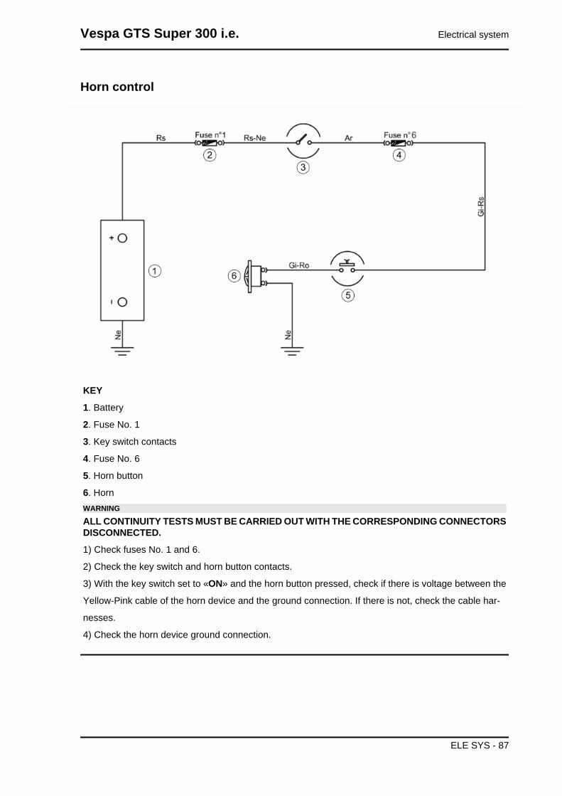
Horn control
KEY
1. Battery
2. Fuse No. 1
3. Key switch contacts
4. Fuse No. 6
5. Horn button
6. HornWARNING
ALL CONTINUITY TESTS MUST BE CARRIED OUT WITH THE CORRESPONDING CONNECTORSDISCONNECTED.
1) Check fuses No. 1 and 6.
2) Check the key switch and horn button contacts.
3) With the key switch set to «ON» and the horn button pressed, check if there is voltage between the
Yellow-Pink cable of the horn device and the ground connection. If there is not, check the cable har-
nesses.
4) Check the horn device ground connection.
Vespa GTS Super 300 i.e. Electrical system
ELE SYS - 87

Turn signals system check
KEY
1. Battery
2. Fuse No. 1
3. Key switch contacts
4. Fuse No. 6
5. Turn indicator control device
6. Turn indicator switch
7. Turn indicator bulbsWARNING
ALL CONTINUITY TESTS MUST BE CARRIED OUT WITH THE CORRESPONDING CONNECTORSDISCONNECTED.
1) Check that bulbs operate properly.
2) Check fuses No. 1 and 6.
3) Check key switch contacts.
4) With the ignition key set to «ON», check if there is voltage between the Blue-Black cable of the turn
indicators switch and the ground connection. If there is not, check the cable harnesses and the con-
nections of the turn indicator control device.
5) Check the turn indicator switch contacts.
6) With the turn indicator switch pressed to the right, check if there is voltage between the White-Blue
cable of the switch and the ground connection. If there is not, check the cable harnesses.
Electrical system Vespa GTS Super 300 i.e.
ELE SYS - 88
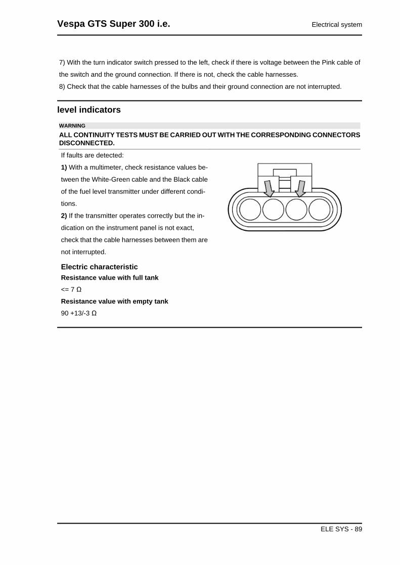
7) With the turn indicator switch pressed to the left, check if there is voltage between the Pink cable of
the switch and the ground connection. If there is not, check the cable harnesses.
8) Check that the cable harnesses of the bulbs and their ground connection are not interrupted.
level indicatorsWARNING
ALL CONTINUITY TESTS MUST BE CARRIED OUT WITH THE CORRESPONDING CONNECTORSDISCONNECTED.
If faults are detected:
1) With a multimeter, check resistance values be-
tween the White-Green cable and the Black cable
of the fuel level transmitter under different condi-
tions.
2) If the transmitter operates correctly but the in-
dication on the instrument panel is not exact,
check that the cable harnesses between them are
not interrupted.
Electric characteristicResistance value with full tank<= 7 Ω
Resistance value with empty tank90 +13/-3 Ω
Vespa GTS Super 300 i.e. Electrical system
ELE SYS - 89
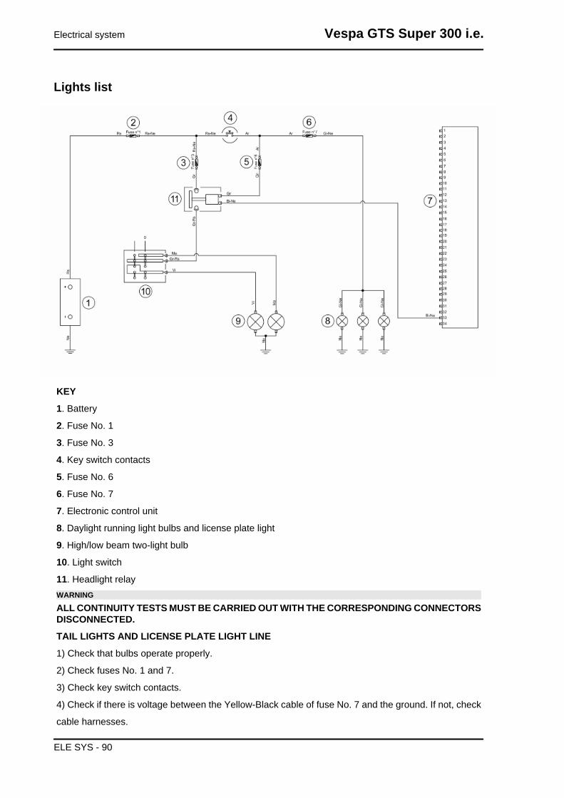
Lights list
KEY
1. Battery
2. Fuse No. 1
3. Fuse No. 3
4. Key switch contacts
5. Fuse No. 6
6. Fuse No. 7
7. Electronic control unit
8. Daylight running light bulbs and license plate light
9. High/low beam two-light bulb
10. Light switch
11. Headlight relayWARNING
ALL CONTINUITY TESTS MUST BE CARRIED OUT WITH THE CORRESPONDING CONNECTORSDISCONNECTED.
TAIL LIGHTS AND LICENSE PLATE LIGHT LINE
1) Check that bulbs operate properly.
2) Check fuses No. 1 and 7.
3) Check key switch contacts.
4) Check if there is voltage between the Yellow-Black cable of fuse No. 7 and the ground. If not, check
cable harnesses.
Electrical system Vespa GTS Super 300 i.e.
ELE SYS - 90

5) Check that the cable harnesses of the bulbs and their ground connection are not interrupted.
HIGH BEAM/LOW BEAM LIGHTS LINE
1) Check that bulbs operate properly.
2) Check fuses No. 1, 3 and 6.
3) Check key switch contacts.
4) Check if there is voltage between the Grey cable of the headlight relay and the ground connection.
If there is not, check the cable harnesses.
5) With the key switch set to «ON» and the engine running, check if there is voltage between the Yellow-
Red cable of the headlight relay and the ground connection. If there is not, check the cable harnesses.
6) Check that the White-Black cable connecting the headlight relay switch and the control unit (pin 19)
is not interrupted.
7) Check the headlight remote control switch.
8) Check that the Grey-Red cable of the light switch and the headlight relay switch is not interrupted.
9) Check the light switch contacts.
10) Check that the cable harnesses of the bulbs and their ground connection are not interrupted.
Fuses
The electrical system is equipped with:
1. six protection fuses «A» located in the glove
compartment to the left
2. of a fuse «B», located in the battery compart-
ment.
The chart shows the position and specifications of
the fuses in the vehicle.CAUTION
BEFORE REPLACING A BLOWN FUSE, FIND AND SOLVETHE FAILURE THAT CAUSED IT TO BLOW. NEVER TRYTO REPLACE A FUSE WITH ANY OTHER MATERIAL (APIECE OF ELECTRIC WIRE, FOR INSTANCE).CAUTION
MODIFICATIONS OR REPAIRS TO THE ELECTRICAL SYS-TEM, PERFORMED INCORRECTLY OR WITHOUT STRICTATTENTION TO THE TECHNICAL SPECIFICATIONS OFTHE SYSTEM CAN CAUSE MALFUNCTIONING AND RISKOF FIRE.
FUSE «B»Specification Desc./Quantity
1 Fuse no. 1 Capacity: 30 AProtected circuits: Main system.
Vespa GTS Super 300 i.e. Electrical system
ELE SYS - 91

FUSES «A» ABS VERSIONSpecification Desc./Quantity
1 Fuse no. 2 Capacity: 7.5 AProtected circuits: Inclination sensor, starter button,
control unit, immobilizer aerial, ABS control unit.2 Fuse No. 3 Capacity: 10 A
Protected circuits: Control unit.3 Fuse No. 4 Capacity: 7.5 A
Protected circuits: Pre-installation for anti-theft device,turn indicators, horn, lights relay, stop lights, USB sock-
et.4 Fuse No. 5 Capacity: 15 A
Protected circuits: Front headlight, electric fan, Pre-in-stallation for anti-theft device, instrument panel, ignition
switch.5 Fuse No. 6 Capacity: 7.5 A
Protected circuits: Taillight, instrument panel, front turnindicators.
6 Fuse No. 7 Capacity: 20 AProtected circuits: ABS control unit.
FUSES «A»Specification Desc./Quantity
1 Fuse no. 2 Capacity: 7.5 AProtected circuits: Inclination sensor, starter button,
control unit, immobilizer aerial.2 Fuse No. 3 Capacity: 10 A
Protected circuits: Control unit.3 Fuse No. 4 Capacity: 7.5 A
Protected circuits: Pre-installation for anti-theft device,turn indicators, horn, lights relay, stop lights, USB sock-
et.4 Fuse No. 5 Capacity: 15 A
Protected circuits: Front headlight, electric fan, Pre-in-stallation for anti-theft device, instrument panel, ignition
switch.5 Fuse No. 6 Capacity: 7.5 A
Protected circuits: Taillight, instrument panel, front turnindicators.
Electrical system Vespa GTS Super 300 i.e.
ELE SYS - 92

Dashboard
A = Speedometer
B = Immobilizer warning light /engine temperature
C = Engine control warning light/ASR (where available)
D = Turn indicator warning light
E = Low fuel warning light
F= Digital display
G = Insufficient oil pressure warning light
H = High beam warning light
I = ABS warning light (where available)
Sealed batteryIf the vehicle is provided with a sealed battery, the only maintenance required is the check of its charge
and recharging, if necessary.
These operations should be carried out before delivering the vehicle, and on a six-month basis while
the vehicle is stored in open circuit.
Besides upon pre-delivery it is therefore necessary to check the battery charge and recharge it, if re-
quired, before storing the vehicle and afterwards every six months.
INSTRUCTIONS FOR BATTERY REFRESH AFTER OPEN CIRCUIT STORAGE
1) Voltage check
Before installing the battery on the vehicle, check the open circuit voltage with a standard tester.
Vespa GTS Super 300 i.e. Electrical system
ELE SYS - 93

- If voltage exceeds 12.60 V, the battery can be installed without any renewal recharge.
- If voltage is below 12.60 V, a renewal recharge is required as explained in 2).
2) Constant voltage battery charge mode
- Constant voltage charge equal to 14.40 to 14.70V
- Initial charge voltage equal to 0.3 to 0.5 for Nominal capacity
- Charge time:
10 to 12 h recommended
Minimum 6 h
Maximum 24 h
3) Constant current battery charge mode
- Charge current equal to 1/10 of the battery rated capacity
- Charge time: Maximum 5 h
Battery installation
VRLA battery (valve-regulated lead-acid battery) Maintenance Free (MF)WARNING
BATTERY ELECTROLYTE IS TOXIC AND IT MAY CAUSE SERIOUS BURNS. IT CONTAINS SUL-PHURIC ACID. AVOID CONTACT WITH YOUR EYES, SKIN AND CLOTHING. IF IT ACCIDENTALLYCOMES INTO CONTACT WITH YOUR EYES OR SKIN, WASH WITH ABUNDANT WATER FORAPPROX. 15 MIN. AND SEEK IMMEDIATE MEDICAL ATTENTION.IF ACCIDENTALLY SWALLOWED, IMMEDIATELY DRINK LARGE QUANTITIES OF WATER ORMILK FOLLOWED BY MAGNESIUM MILK, BEATEN EGG OR VEGETABLE OIL. SEEK IMMEDIATEMEDICAL ATTENTION.BATTERIES PRODUCE EXPLOSIVE GASES; KEEP CLEAR OF NAKED FLAMES, SPARKS ORCIGARETTES; VENTILATE THE AREA WHEN RECHARGING INDOORS.ALWAYS WEAR EYE PROTECTION WHEN WORKING IN THE PROXIMITY OF BATTERIES.KEEP OUT OF THE REACH OF CHILDREN
1) Battery preparation
Position the battery on a flat surface. Remove the
adhesive sheet closing cells and proceed as quick-
ly as possible to run the subsequent activation
phases.
Electrical system Vespa GTS Super 300 i.e.
ELE SYS - 94

2) Electrolyte preparation.
Remove the container of the electrolyte from the
pack. Remove and preserve cover strips from the
container, in fact, the strip will later be used as a
closing cover.
Note: Do not pierce the sealing of the container or
the container itself because inside there is sulphu-
ric acid.
3) Procedure for filling the battery with acid.
Position the electrolyte container upside down with
the six areas sealed in line with the six battery filler
holes. Push the container down with enough force
to break the seals. The electrolyte should start to
flow inside the battery.
Note: Do not tilt the container to prevent the flow
of electrolyte from pausing or stopping.
4) Control the flow of electrolyte
Make sure air bubbles are rising from all six filling holes. Leave the container in this position for 20
minutes or more.
Note:If there are no air bubbles coming out of the filling holes, lightly tap the bottom of the container
two or three times. Do not remove the container from the battery.
5) Take out the container.
Make sure all the electrolyte in the battery is drained. Gently tap the bottom of the container if electrolyte
remains in the container. Now, gently pull the container out from the battery, only do this when the
container is completely empty, and proceed immediately to the next point.
6) Battery closing.
Insert the airtight cover strips into the filling holes. Press horizontally with both hands and make sure
that the strip is levelled with the top part of the battery.
Note:To do this, do not use sharp objects that could damage the closing strip, use gloves to protect
your hands and do not bring your face close to the battery.
The filling process is now complete.
Do not remove the strip of caps under any circumstances, do not add water or electrolyte.
Place the battery down for 1 to 2 hours prior to the charging from the battery.
Vespa GTS Super 300 i.e. Electrical system
ELE SYS - 95
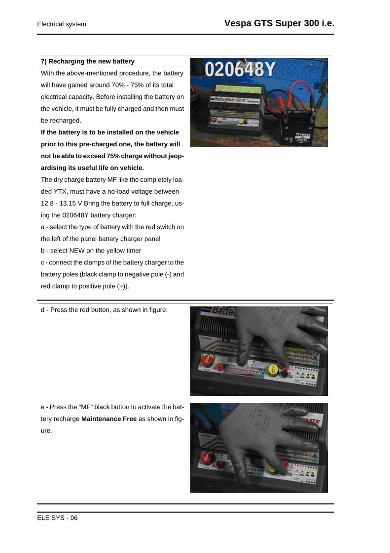
7) Recharging the new battery
With the above-mentioned procedure, the battery
will have gained around 70% - 75% of its total
electrical capacity. Before installing the battery on
the vehicle, it must be fully charged and then must
be recharged.
If the battery is to be installed on the vehicle
prior to this pre-charged one, the battery will
not be able to exceed 75% charge without jeop-
ardising its useful life on vehicle.
The dry charge battery MF like the completely loa-
ded YTX, must have a no-load voltage between
12.8 - 13.15 V Bring the battery to full charge, us-
ing the 020648Y battery charger:
a - select the type of battery with the red switch on
the left of the panel battery charger panel
b - select NEW on the yellow timer
c - connect the clamps of the battery charger to the
battery poles (black clamp to negative pole (-) and
red clamp to positive pole (+)).
d - Press the red button, as shown in figure.
e - Press the "MF" black button to activate the bat-
tery recharge Maintenance Free as shown in fig-
ure.
Electrical system Vespa GTS Super 300 i.e.
ELE SYS - 96

f - Check the ignition of the green LED indicated
with a red arrow in figure.
g - The activation cycle of the new battery lasts for
30 minutes after the ignition of the recharge LED
has taken place
h - Disconnect the clamps from the battery and
check the voltage, if voltages are detected of less
than 12.8 V, proceed with a new recharge of the
battery starting from point c of the recharge pro-
cedure of the new battery, otherwise go to point i
i - The battery is now completely activated, disconnect the battery charger from the fuel supply grid,
disconnect the clamps from the battery and proceed to fitting the battery on the vehicle.
Vespa GTS Super 300 i.e. Electrical system
ELE SYS - 97

Connectors
DIAGNOSTICS CONNECTOR
1. Not connected
2. Ground lead (Black)
3. Electronic control unit (Violet - White)
PICKUP CONNECTOR
1. Control unit positive (Red)
2. Negative from control unit (Brown)
3. Not connected
FUEL PUMP CONNECTOR
1. Power from solenoid (Black - Green)
2. Fuel level indicator (White-Green)
3. Ground lead (Black)
4. Low fuel warning light (Grey-black)
ELECTRONIC CONTROL UNIT CONNECTOR
1. H.V. COIL (Pink-Black)
2. Not connected
3. Not connected
4. Engine switch (Grey-Green)
5. Not connected
6. Live supply (Red-White)
7. Ground No. 1 (Black)
8. Not connected
9. Battery-powered (Grey-Black)
10. Start-up signal (Orange-Blue)
Electrical system Vespa GTS Super 300 i.e.
ELE SYS - 98

11. Lambda probe positive (Sky blue-Black)
12. Lambda probe negative (White-Green)
13. Water temperature sensor (Sky blue-Green)
14. Immobilizer aerial (Orange-White)
15. Not connected
16. K serial line (Purple-White)
17. Immobilizer (Red-Green)
18. Not connected
19. Side stand (Grey-Green)
20. Speed sensor negative (Brown)
21. Not connected
22. Injection load relay (Black-Purple)
23. Not connected
24. Consent to radiator electric fan (Blue-Yellow)
25. Injection warning light (Brown-Black)
26. Not connected
27. Not connected
28. Not connected
29. Engine speed sensor positive (Red)
30. Not connected
31. Lambda probe heater (White)
32. Not connected
33. Low beam lights automatic ignition enabling
(White-Black)
34. Fuel injector (Red-Yellow)
ENGINE TEMPERATURE SENSOR CONNEC-
TOR
1. Ground lead (Grey-Green)
2. Instrument panel (Green-Yellow)
3. Electronic control unit (Sky blue - Green)
4. Ground lead (Black)
Vespa GTS Super 300 i.e. Electrical system
ELE SYS - 99
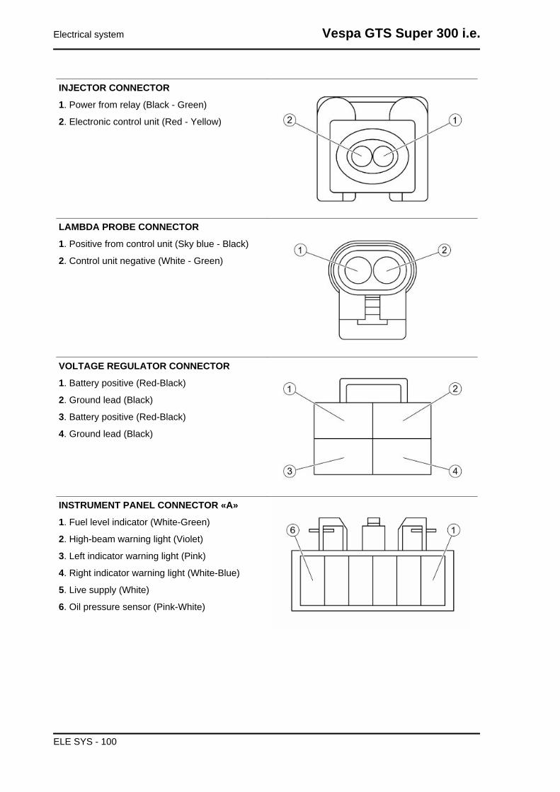
INJECTOR CONNECTOR
1. Power from relay (Black - Green)
2. Electronic control unit (Red - Yellow)
LAMBDA PROBE CONNECTOR
1. Positive from control unit (Sky blue - Black)
2. Control unit negative (White - Green)
VOLTAGE REGULATOR CONNECTOR
1. Battery positive (Red-Black)
2. Ground lead (Black)
3. Battery positive (Red-Black)
4. Ground lead (Black)
INSTRUMENT PANEL CONNECTOR «A»
1. Fuel level indicator (White-Green)
2. High-beam warning light (Violet)
3. Left indicator warning light (Pink)
4. Right indicator warning light (White-Blue)
5. Live supply (White)
6. Oil pressure sensor (Pink-White)
Electrical system Vespa GTS Super 300 i.e.
ELE SYS - 100
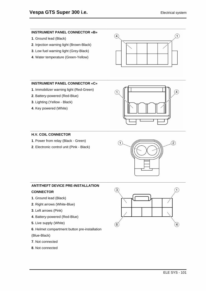
INSTRUMENT PANEL CONNECTOR «B»
1. Ground lead (Black)
2. Injection warning light (Brown-Black)
3. Low fuel warning light (Grey-Black)
4. Water temperature (Green-Yellow)
INSTRUMENT PANEL CONNECTOR «C»
1. Immobilizer warning light (Red-Green)
2. Battery-powered (Red-Blue)
3. Lighting (Yellow - Black)
4. Key powered (White)
H.V. COIL CONNECTOR
1. Power from relay (Black - Green)
2. Electronic control unit (Pink - Black)
ANTITHEFT DEVICE PRE-INSTALLATION
CONNECTOR
1. Ground lead (Black)
2. Right arrows (White-Blue)
3. Left arrows (Pink)
4. Battery-powered (Red-Blue)
5. Live supply (White)
6. Helmet compartment button pre-installation
(Blue-Black)
7. Not connected
8. Not connected
Vespa GTS Super 300 i.e. Electrical system
ELE SYS - 101

IMMOBILIZER ANTENNA CONNECTOR
1. Key powered (Red-White)
2. Ground lead (Black)
3. Electronic control unit (Orange-White)
Diagnostic instrument
STARTER COMMAND
Function
Commands engine starting through the injection control unit.
Operation / Operating principle
The starter button, the brake switches, the starter relay and the injection control unit through PIN 10
are involved.
ELECTRICAL ERRORS
Starter command P0170 - shorted to positive.
Error cause
Shorted to positive: excessive voltage at PIN 10 of the control unit connector.
Troubleshooting
Short circuit to positive:
- This malfunction is detected with a brake activated and the starter button pressed.
- If the battery voltage does not drop (thanks to the absorption of the starter command relay excitation
coil) the control unit understands that PIN 10 is shorted to battery.
- Restore the cabling (if the short is in the cabling) or the relay (if the short is in the relay).
COIL
Function
Allows generation of the electrical discharge on
the spark plug, with an increase of voltage.
Pinout:
1. Power from relay
2. Activation by control unit (control unit side PIN
1)
ELECTRICAL ERRORS
H.V. Coil P0351 - shorted to positive / open circuit or shorted to negative.
Error cause
Electrical system Vespa GTS Super 300 i.e.
ELE SYS - 102

Shorted to positive: excessive voltage at PIN 1 of the control unit connector.
Circuit open or short circuit to negative:interruption of the circuit or null voltage at PIN 1 of the control
unit connector.
Troubleshooting
Short circuit to positive:
- Disconnect the coil connector, turn the key to ON and activate the component through the diagnostics
instrument.
- Verify the presence of voltage on the coil connector PIN 2: if present, restore the cabling, otherwise
replace the coil.
Open circuit:
- Carry out the check procedure of the coil and control unit connectors.
- Verify continuity of the cabling between the coil and control unit: Coil PIN 2 - control unit PIN 1. If there
is no continuity, restore the cable harness.
- Verify, with the key turned ON, the presence of voltage on the coil connector PIN 1. If no voltage is
detected, check that the cable harness between the coil and injection relay is not interrupted: PIN 1 coil
- relay.
- If the above tests provided a positive result, the coil should be replaced.
Short circuit to negative:
- Disconnect the control unit connector and the coil connector.
- Verify the coil connector PIN 2 ground insulation (or control unit connector PIN 1). If necessary, restore
the cable harness.
INJECTOR
Function
To supply the correct amount of petrol at the right
timing.
Operation / Operating principle
Injector coil is excited for the petrol passage to
open.
Pin-out:
1. Power from relay
2. Control unit ground
ELECTRICAL ERRORS
Injector P0201 - shorted to positive / shorted to negative / open circuit.
Error cause
Shorted to positive: excessive voltage at PIN 34 of the control unit connector.
Shorted to negative: null voltage at PIN 1 of the injector connector.
The circuit is open: interruption of the circuit.
Vespa GTS Super 300 i.e. Electrical system
ELE SYS - 103

Troubleshooting
Shorted to positive:
- Disconnect the injector connector, turn ignition switch to ON and activate the component using the
diagnostic tool.
- Verify the absence of voltage at the injector connector PIN 2; if present restore the cable harness,
otherwise proceed with the following checks.
Shorted to negative:
- Disconnect the injector connector, turn ignition switch to ON and activate the component using the
diagnostic tool.
- Verify the presence of voltage at the ends of the injector connector; if there is no voltage, restore the
cable harness, otherwise proceed with the following checks.
The circuit is open:
- Perform the check of the injector and control unit connectors.
- Verify continuity of the cable harness between the control unit connector and the injector connector
(control unit PIN 34 - injector PIN 2). If there is no continuity, restore the cable harness.
FUEL PUMP
ELECTRICAL ERRORS
Fuel pump relay P0230 - shorted to positive / shorted to negative / open circuit.
Error cause
Shorted to positive: excessive voltage at PIN 22 of the control unit connector.
Short circuit to negative: null voltage at PIN 86 of the injection relay.
Open circuit: circuit interruption.
Troubleshooting
Short circuit to positive:
- Disconnect the injection relay, turn the key to ON and activate the relay through the diagnostics in-
strument.
- Verify the presence of voltage between relay connector PIN 86 and 85 toward the cabling.
- If no voltage is read, disconnect the control unit and verify insulation from battery positive of the relay
PIN 85 (or control unit PIN 22). If necessary, restore the cable harness.
Short circuit to negative:
- Disconnect the injection relay and the control unit.
- Verify ground insulation of the relay connector PIN 86 and 85 toward the cabling: if there is no insu-
lation, restore the cabling.
Open circuit:
- Disconnect the injection relay and the control unit.
- Verify continuity of the cabling between the relay and control unit: Relay PIN 85 - control unit PIN 22.
If necessary, restore the cable harness.
Electrical system Vespa GTS Super 300 i.e.
ELE SYS - 104

ELECTRIC FAN CIRCUIT
Function
Radiator fan and coolant - Operation.
Operation / Operating principle
The control unit closes the fan control relay excitation circuit to ground until the temperature drops.
ELECTRICAL ERRORS
Fan relay P0480 - shorted to positive / shorted to negative / open circuit.
Error cause
Shorted to positive: excessive voltage at PIN 24 of the control unit connector.
Shorted to negative: null voltage at PIN 24 of the control unit connector.
Open circuit: circuit interruption.
Troubleshooting
Short circuit to positive:
- Disconnect the fan control relay and, turning the key to ON position, measure the voltage read at PIN
85 of the relay connector to the cable harness: if the voltage is 12V restore the cabling. If the voltage
is zero replace the relay.
Short circuit to negative:
- Disconnect the fan control relay and the control unit.
- Verify ground insulation of the cable between the fan control relay (PIN 85) and the control unit (PIN
24). Restore the cabling if necessary.
Open circuit:
- Carry out the check procedure of the control unit and relay connectors.
- Verify electrical continuity of the cable between the relay connector (PIN 85) and the control unit
connector (PIN 24).
- Verify electrical continuity of the cable between the relay connector (PIN 30) and the secondary fuse
holders.
- Verify continuity between relay PIN 85 and PIN 86. If there is no continuity replace the relay.
ENGINE TEMPERATURE SENSOR
Function
Serves the purpose of communicating the engine
temperature to the control unit in order to optimise
performance.
Operation / Operating principle
NTC type sensor (resistance sensor, inversely
variable with temperature).
Pinout:
Vespa GTS Super 300 i.e. Electrical system
ELE SYS - 105
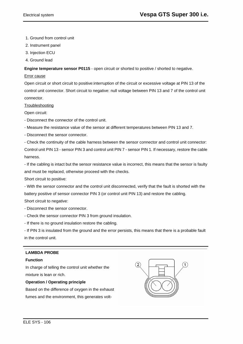
1. Ground from control unit
2. Instrument panel
3. Injection ECU
4. Ground lead
Engine temperature sensor P0115 - open circuit or shorted to positive / shorted to negative.
Error cause
Open circuit or short circuit to positive:interruption of the circuit or excessive voltage at PIN 13 of the
control unit connector. Short circuit to negative: null voltage between PIN 13 and 7 of the control unit
connector.
Troubleshooting
Open circuit:
- Disconnect the connector of the control unit.
- Measure the resistance value of the sensor at different temperatures between PIN 13 and 7.
- Disconnect the sensor connector.
- Check the continuity of the cable harness between the sensor connector and control unit connector:
Control unit PIN 13 - sensor PIN 3 and control unit PIN 7 - sensor PIN 1. If necessary, restore the cable
harness.
- If the cabling is intact but the sensor resistance value is incorrect, this means that the sensor is faulty
and must be replaced, otherwise proceed with the checks.
Short circuit to positive:
- With the sensor connector and the control unit disconnected, verify that the fault is shorted with the
battery positive of sensor connector PIN 3 (or control unit PIN 13) and restore the cabling.
Short circuit to negative:
- Disconnect the sensor connector.
- Check the sensor connector PIN 3 from ground insulation.
- If there is no ground insulation restore the cabling.
- If PIN 3 is insulated from the ground and the error persists, this means that there is a probable fault
in the control unit.
LAMBDA PROBE
Function
In charge of telling the control unit whether the
mixture is lean or rich.
Operation / Operating principle
Based on the difference of oxygen in the exhaust
fumes and the environment, this generates volt-
Electrical system Vespa GTS Super 300 i.e.
ELE SYS - 106
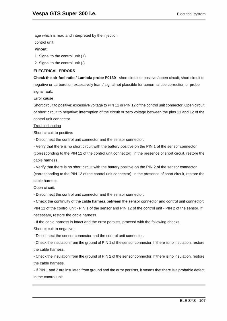
age which is read and interpreted by the injection
control unit.
Pinout:
1. Signal to the control unit (+)
2. Signal to the control unit (-)
ELECTRICAL ERRORS
Check the air-fuel ratio / Lambda probe P0130 - short circuit to positive / open circuit, short circuit to
negative or carburetion excessively lean / signal not plausible for abnormal title correction or probe
signal fault.
Error cause
Short circuit to positive: excessive voltage to PIN 11 or PIN 12 of the control unit connector. Open circuit
or short circuit to negative: interruption of the circuit or zero voltage between the pins 11 and 12 of the
control unit connector.
Troubleshooting
Short circuit to positive:
- Disconnect the control unit connector and the sensor connector.
- Verify that there is no short circuit with the battery positive on the PIN 1 of the sensor connector
(corresponding to the PIN 11 of the control unit connector); in the presence of short circuit, restore the
cable harness.
- Verify that there is no short circuit with the battery positive on the PIN 2 of the sensor connector
(corresponding to the PIN 12 of the control unit connector); in the presence of short circuit, restore the
cable harness.
Open circuit:
- Disconnect the control unit connector and the sensor connector.
- Check the continuity of the cable harness between the sensor connector and control unit connector:
PIN 11 of the control unit - PIN 1 of the sensor and PIN 12 of the control unit - PIN 2 of the sensor. If
necessary, restore the cable harness.
- If the cable harness is intact and the error persists, proceed with the following checks.
Short circuit to negative:
- Disconnect the sensor connector and the control unit connector.
- Check the insulation from the ground of PIN 1 of the sensor connector. If there is no insulation, restore
the cable harness.
- Check the insulation from the ground of PIN 2 of the sensor connector. If there is no insulation, restore
the cable harness.
- If PIN 1 and 2 are insulated from ground and the error persists, it means that there is a probable defect
in the control unit.
Vespa GTS Super 300 i.e. Electrical system
ELE SYS - 107

INDEX OF TOPICS
ENGINE FROM VEHICLE ENG VE

Questa sezione descrive le operazioni da effettuare per lo smontaggio del motore dal veicolo.
Exhaust assy. Removal
- Remove the right and left fairings and the spoiler terminals.
- Remove the Lambda probe from its support and
disconnect it.
Remove the clamp holding the lambda probe ca-
ble to the coolant pipe indicated in the photograph
- Undo the two exhaust manifold fixings on the
head. To unscrew the nuts that fix the silencer
flange to the head properly, use a jointed wrench
that allows, according to the travel direction, to get
also at the right nut. That is difficult to do with a
traditional straight wrench.
- Undo the three screws that fix the silencer to the
supporting arm.
- Remove the full silencer unit.
Vespa GTS Super 300 i.e. Engine from vehicle
ENG VE - 109
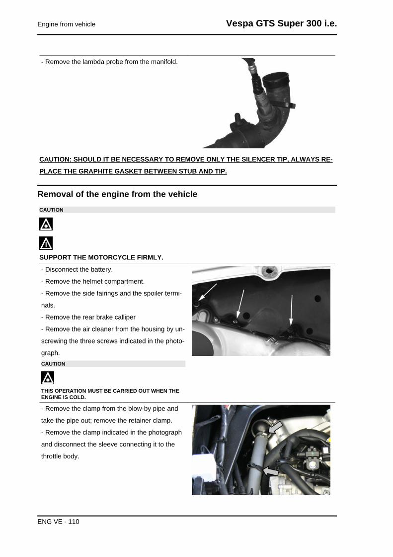
- Remove the lambda probe from the manifold.
CAUTION: SHOULD IT BE NECESSARY TO REMOVE ONLY THE SILENCER TIP, ALWAYS RE-
PLACE THE GRAPHITE GASKET BETWEEN STUB AND TIP.
Removal of the engine from the vehicleCAUTION
SUPPORT THE MOTORCYCLE FIRMLY.
- Disconnect the battery.
- Remove the helmet compartment.
- Remove the side fairings and the spoiler termi-
nals.
- Remove the rear brake calliper
- Remove the air cleaner from the housing by un-
screwing the three screws indicated in the photo-
graph.CAUTION
THIS OPERATION MUST BE CARRIED OUT WHEN THEENGINE IS COLD.
- Remove the clamp from the blow-by pipe and
take the pipe out; remove the retainer clamp.
- Remove the clamp indicated in the photograph
and disconnect the sleeve connecting it to the
throttle body.
Engine from vehicle Vespa GTS Super 300 i.e.
ENG VE - 110
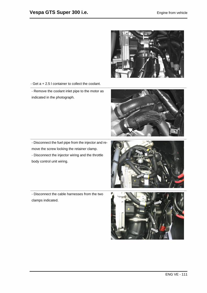
- Get a + 2.5 l container to collect the coolant.
- Remove the coolant inlet pipe to the motor as
indicated in the photograph.
- Disconnect the fuel pipe from the injector and re-
move the screw locking the retainer clamp.
- Disconnect the injector wiring and the throttle
body control unit wiring.
- Disconnect the cable harnesses from the two
clamps indicated.
Vespa GTS Super 300 i.e. Engine from vehicle
ENG VE - 111

- Remove the coolant outlet pipe from the engine
as indicated.
- Remove the spark plug cap.
- Remove the coolant temperature sensor con-
nector indicated in the photo.
- Remove the throttle control cables from the throt-
tle body by undoing the nuts indicated in the pho-
tograph.
- Loosen the clamp indicated in the photograph
and remove the throttle body.
Engine from vehicle Vespa GTS Super 300 i.e.
ENG VE - 112

- Remove the clamp retaining the starter motor
from the sleeve.
- Remove the positive and negative wiring from the
starter motor as shown in the picture.
- Disconnect the connectors from the flywheel wir-
ing as shown in the photo.
- Release the cables from the retainer clamps.
Vespa GTS Super 300 i.e. Engine from vehicle
ENG VE - 113

- Remove the four retainers of the rear brake pipes
from the crankcase.
- Remove the rear shock absorbers.
- Remove the engine-swinging arm fixing pin by
undoing the nut and operating on the head of the
pin as shown in the photograph.
- The engine is now free.
Upon refitting the engine to the vehicle, carry out
the removal operations but in reverse order, and
respect the tightening torque shown in the «Spec-
ifications» Chapter.
- Check that there is a small clearance when the
valve is in abutment against the set screw.
- Check the engine oil level and if necessary, top
it up with the recommended type.
- Fill and bleed the cooling circuit.
- Check accelerator and electric devices for correct
functioning.
Engine from vehicle Vespa GTS Super 300 i.e.
ENG VE - 114

- Pay particular attention to the sleeve, be careful
to position the throttle body reference marks as in-
dicated in the picture.CAUTIONPAY PARTICULAR ATTENTION TO POSITIONING THETHROTTLE CONTROL TRANSMISSION PROPERLY.
Vespa GTS Super 300 i.e. Engine from vehicle
ENG VE - 115

INDEX OF TOPICS
ENGINE ENG
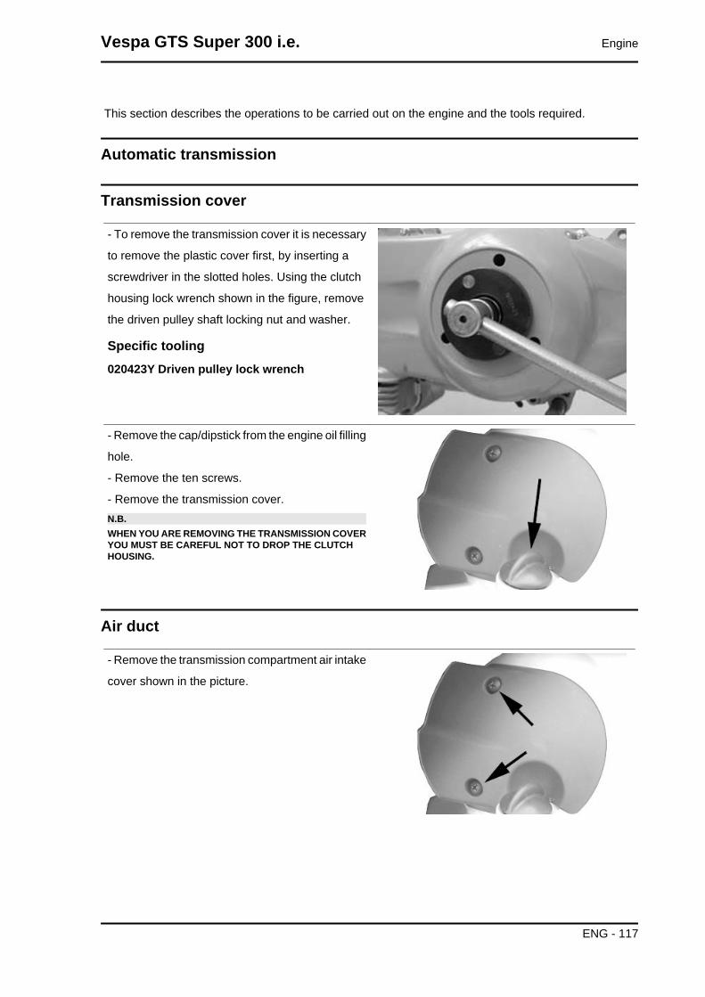
This section describes the operations to be carried out on the engine and the tools required.
Automatic transmission
Transmission cover
- To remove the transmission cover it is necessary
to remove the plastic cover first, by inserting a
screwdriver in the slotted holes. Using the clutch
housing lock wrench shown in the figure, remove
the driven pulley shaft locking nut and washer.
Specific tooling020423Y Driven pulley lock wrench
- Remove the cap/dipstick from the engine oil filling
hole.
- Remove the ten screws.
- Remove the transmission cover.N.B.WHEN YOU ARE REMOVING THE TRANSMISSION COVERYOU MUST BE CAREFUL NOT TO DROP THE CLUTCHHOUSING.
Air duct
- Remove the transmission compartment air intake
cover shown in the picture.
Vespa GTS Super 300 i.e. Engine
ENG - 117

- Remove the 5 screws, found on two different lev-
els, as well as the small casing.
Removing the driven pulley shaft bearing
- Remove the clip from the inside of the cover.
- Remove the bearing from the crankcase by
means of:
Specific tooling020376Y Adapter handle
020375Y 28 x 30 mm adaptor
020412Y 15 mm guide
Refitting the driven pulley shaft bearing
- Slightly heat the crankcase from the inside so as
not to damage the painted surface.
- Insert the bearing in its seat.
- Refit the Seeger ring.CAUTIONUSE AN APPROPRIATE REST SURFACE TO AVOID DAM-AGING THE COVER PAINT.N.B.ALWAYS REPLACE THE BEARING WITH A NEW ONEUPON REFITTING.
Specific tooling020376Y Adapter handle
020357Y 32 x 35 mm adaptor
020412Y 15 mm guide
Baffle roller
Engine Vespa GTS Super 300 i.e.
ENG - 118
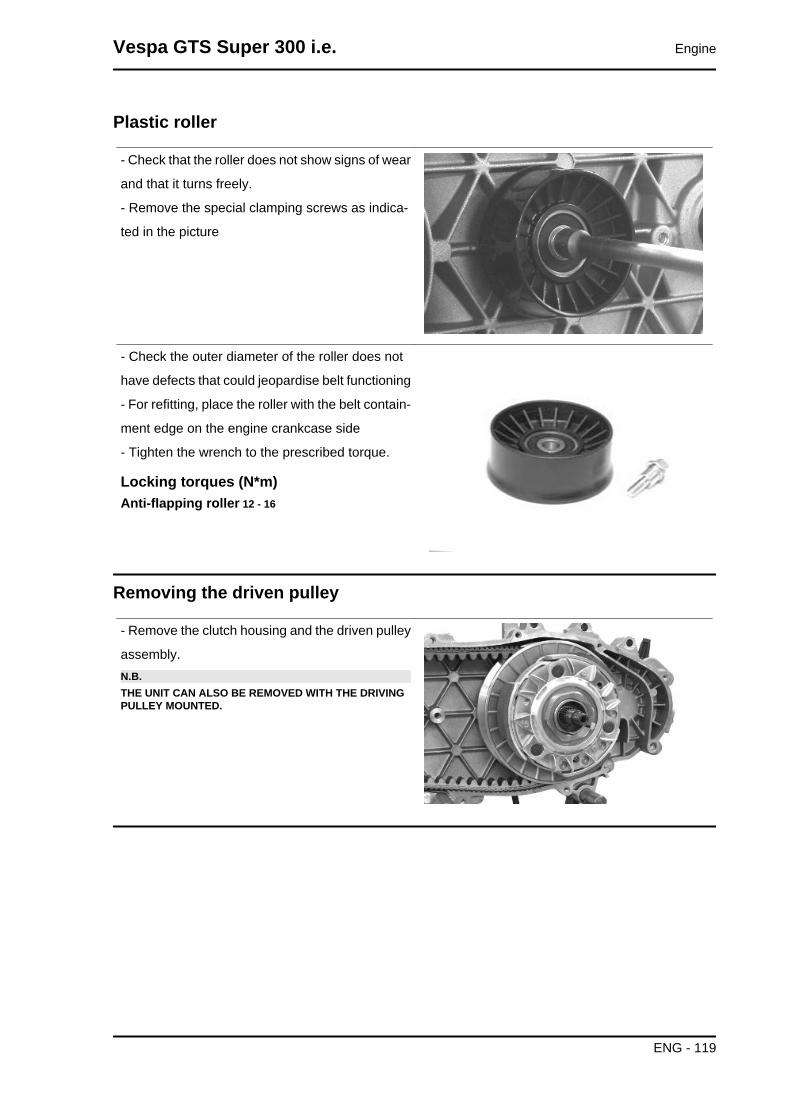
Plastic roller
- Check that the roller does not show signs of wear
and that it turns freely.
- Remove the special clamping screws as indica-
ted in the picture
- Check the outer diameter of the roller does not
have defects that could jeopardise belt functioning
- For refitting, place the roller with the belt contain-
ment edge on the engine crankcase side
- Tighten the wrench to the prescribed torque.
Locking torques (N*m)Anti-flapping roller 12 - 16
Removing the driven pulley
- Remove the clutch housing and the driven pulley
assembly.N.B.THE UNIT CAN ALSO BE REMOVED WITH THE DRIVINGPULLEY MOUNTED.
Vespa GTS Super 300 i.e. Engine
ENG - 119
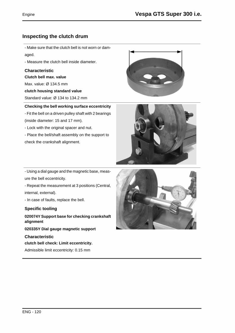
Inspecting the clutch drum
- Make sure that the clutch bell is not worn or dam-
aged.
- Measure the clutch bell inside diameter.
CharacteristicClutch bell max. valueMax. value: Ø 134.5 mm
clutch housing standard valueStandard value: Ø 134 to 134.2 mm
Checking the bell working surface eccentricity
- Fit the bell on a driven pulley shaft with 2 bearings
(inside diameter: 15 and 17 mm).
- Lock with the original spacer and nut.
- Place the bell/shaft assembly on the support to
check the crankshaft alignment.
- Using a dial gauge and the magnetic base, meas-
ure the bell eccentricity.
- Repeat the measurement at 3 positions (Central,
internal, external).
- In case of faults, replace the bell.
Specific tooling020074Y Support base for checking crankshaftalignment
020335Y Dial gauge magnetic support
Characteristicclutch bell check: Limit eccentricity.Admissible limit eccentricity: 0.15 mm
Engine Vespa GTS Super 300 i.e.
ENG - 120

Removing the clutch
Fit the driven pulley spring compressor specific
tool with medium length pins screwed in position
«C» on the tool internal side.
- Introduce the adapter ring 11 with the chamfering
facing the inside of the tool.
- Fit the driven pulley unit on the tool with the in-
sertion of the 3 pins in the ventilation holes in the
mass holder support.
- Make sure that the clutch is perfectly inserted into
the adapter ring before proceeding to loosen/tight-
en the clutch nut.
- Use the special 46x55 wrench component 9 to
remove the nut fixing the clutch in place.
- Dismantle the driven pulley components (Clutch
and spring with its plastic holder)CAUTIONTHE TOOL MUST BE FIRMLY FIXED IN THE CLAMP ANDTHE CENTRAL SCREW MUST BE BROUGHT INTO CON-TACT WITH THE TOOL. EXCESSIVE TORQUE CAN CAUSETHE SPECIFIC TOOL TO BUCKLE.
Specific tooling020444Y011 adapter ring
020444Y009 wrench 46 x 55
020444Y Tool for fitting/removing the clutch onthe driven pulley
Inspecting the clutch
- Check the thickness of the clutch mass friction
material.
- The masses must exhibit no traces of lubricants;
in that case, check the driven pulley unit seals.N.B.UPON RUNNING-IN, THE MASSES MUST EXHIBIT A CEN-TRAL FAYING SURFACE AND MUST NOT BE DIFFERENTFROM ONE ANOTHER.DIFFERENT CONDITIONS MAY CAUSE CLUTCH TEAR-ING.CAUTIONDO NOT USE TOOLS TO OPEN THE MASSES TO AVOIDVARIATION IN THE RETURN SPRING LOAD.
Characteristic
Vespa GTS Super 300 i.e. Engine
ENG - 121
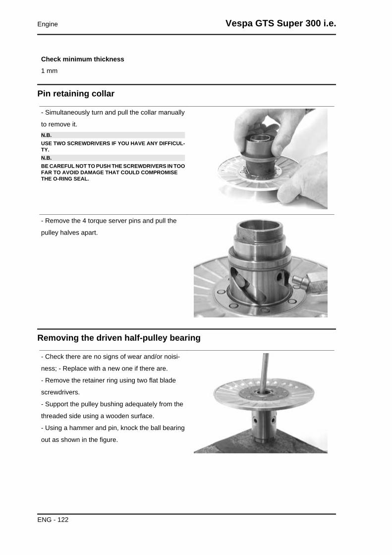
Check minimum thickness1 mm
Pin retaining collar
- Simultaneously turn and pull the collar manually
to remove it.N.B.USE TWO SCREWDRIVERS IF YOU HAVE ANY DIFFICUL-TY.N.B.BE CAREFUL NOT TO PUSH THE SCREWDRIVERS IN TOOFAR TO AVOID DAMAGE THAT COULD COMPROMISETHE O-RING SEAL.
- Remove the 4 torque server pins and pull the
pulley halves apart.
Removing the driven half-pulley bearing
- Check there are no signs of wear and/or noisi-
ness; - Replace with a new one if there are.
- Remove the retainer ring using two flat blade
screwdrivers.
- Support the pulley bushing adequately from the
threaded side using a wooden surface.
- Using a hammer and pin, knock the ball bearing
out as shown in the figure.
Engine Vespa GTS Super 300 i.e.
ENG - 122
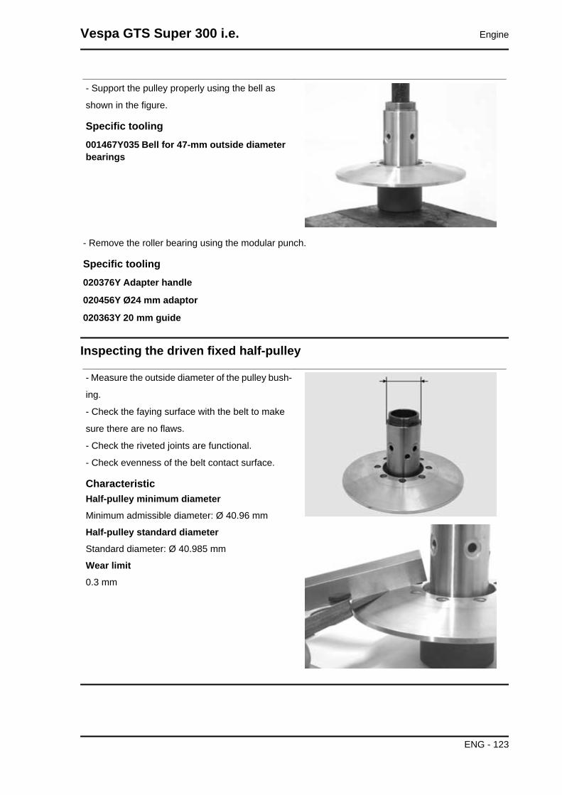
- Support the pulley properly using the bell as
shown in the figure.
Specific tooling001467Y035 Bell for 47-mm outside diameterbearings
- Remove the roller bearing using the modular punch.
Specific tooling020376Y Adapter handle
020456Y Ø24 mm adaptor
020363Y 20 mm guide
Inspecting the driven fixed half-pulley
- Measure the outside diameter of the pulley bush-
ing.
- Check the faying surface with the belt to make
sure there are no flaws.
- Check the riveted joints are functional.
- Check evenness of the belt contact surface.
CharacteristicHalf-pulley minimum diameterMinimum admissible diameter: Ø 40.96 mm
Half-pulley standard diameterStandard diameter: Ø 40.985 mm
Wear limit0.3 mm
Vespa GTS Super 300 i.e. Engine
ENG - 123

Inspecting the driven sliding half-pulley
- Remove the two seal rings and the two O-rings.
- Measure the movable half-pulley bushing inside
diameter.
- Check the faying surface with the belt to make
sure there are no flaws.
- Check the riveted joints are functional.
- Check the evenness of the belt contact surface.
MOVABLE DRIVEN HALF-PULLEY DIMENSIONSSpecification Desc./Quantity
Wear limit 0.3 mmstandard diameter Ø 41.000 - 41.035 mm
maximum allowable diameter Ø 41.08 mm
Refitting the driven half-pulley bearing
- Support the pulley bushing adequately from the
threaded side using a wooden surface.
- Fit a new roller bearing as shown in the figure.
- For the fitting of the new ball bearing, follow the
example in the figure using a modular punch.
Fit the retainer ringWARNINGN.B.FIT THE BALL BEARING WITH THE VISIBLE SHIELDING
Specific tooling020376Y Adapter handle
020375Y 28 x 30 mm adaptor
020424Y Punch for fitting driven pulley rollercasing
Engine Vespa GTS Super 300 i.e.
ENG - 124

Refitting the driven pulley
- Insert the new oil seals and O-rings on the mov-
able half-pulley.
- Lightly grease the O-rings «A» shown in the fig-
ure.
- Fit the half-pulley over the bushing using the spe-
cific tool.
- Check that the pins are not worn and proceed to
refitting them in their slots.
- Refit the torque server closure collar.
- Using a curved-spout grease gun, lubricate the
driven pulley unit with approximately 6 grams of
grease. Apply grease through one of the holes in
the bushing until it comes out through the hole on
the opposite side. This operation is necessary to
avoid the presence of grease beyond the O-rings.N.B.THE TORQUE SERVER CAN BE GREASED WHETHERWITH BEARINGS FITTED OR WHEN THEY ARE BEING RE-PLACED; UNDERTAKING THE OPERATION WHEN THEBEARINGS ARE BEING SERVICED MIGHT BE EASIER.
Specific tooling020263Y Sheath for fitting the driven pulley
Recommended productsAGIP GREASE SM 2 Gray black smooth-tex-tured lithium grease, containing molybdenumdisulphide.-
Vespa GTS Super 300 i.e. Engine
ENG - 125

Inspecting the clutch spring
- Measure the length of the spring when it is re-
laxed.
CharacteristicStandard length123 mm
Acceptable limit after use:118 mm
Refitting the clutch
- Support the driven pulley spring compressor spe-
cific tool with the control screw in vertical axis.
- Arrange the tool with the medium length pins
screwed in position "C" on the inside.
- Introduce the adapter ring No. 11 with the cham-
fering facing upwards.
- Insert the clutch on the adapter ring.
- Lubricate the end of the spring that abuts against
the torque server closing collar.
- Insert the spring with its plastic holder in contact
with the clutch.
- Insert the drive belt into the pulley unit according
to their direction of rotation.
- Insert the pulley unit with the belt into the tool.
- Slightly preload the spring.
- Make sure that the clutch is perfectly inserted into
the adapter ring before proceeding to tighten the
clutch nut.
- Place the tool in the clamp with the control screw
on the horizontal axis.
- Fully preload the spring.
- Apply the clutch fixing nut and tighten it to the
prescribed torque using the special 46x55 wrench.
- Loosen the tool clamp and insert the belt accord-
ing to its direction of rotation.
Engine Vespa GTS Super 300 i.e.
ENG - 126
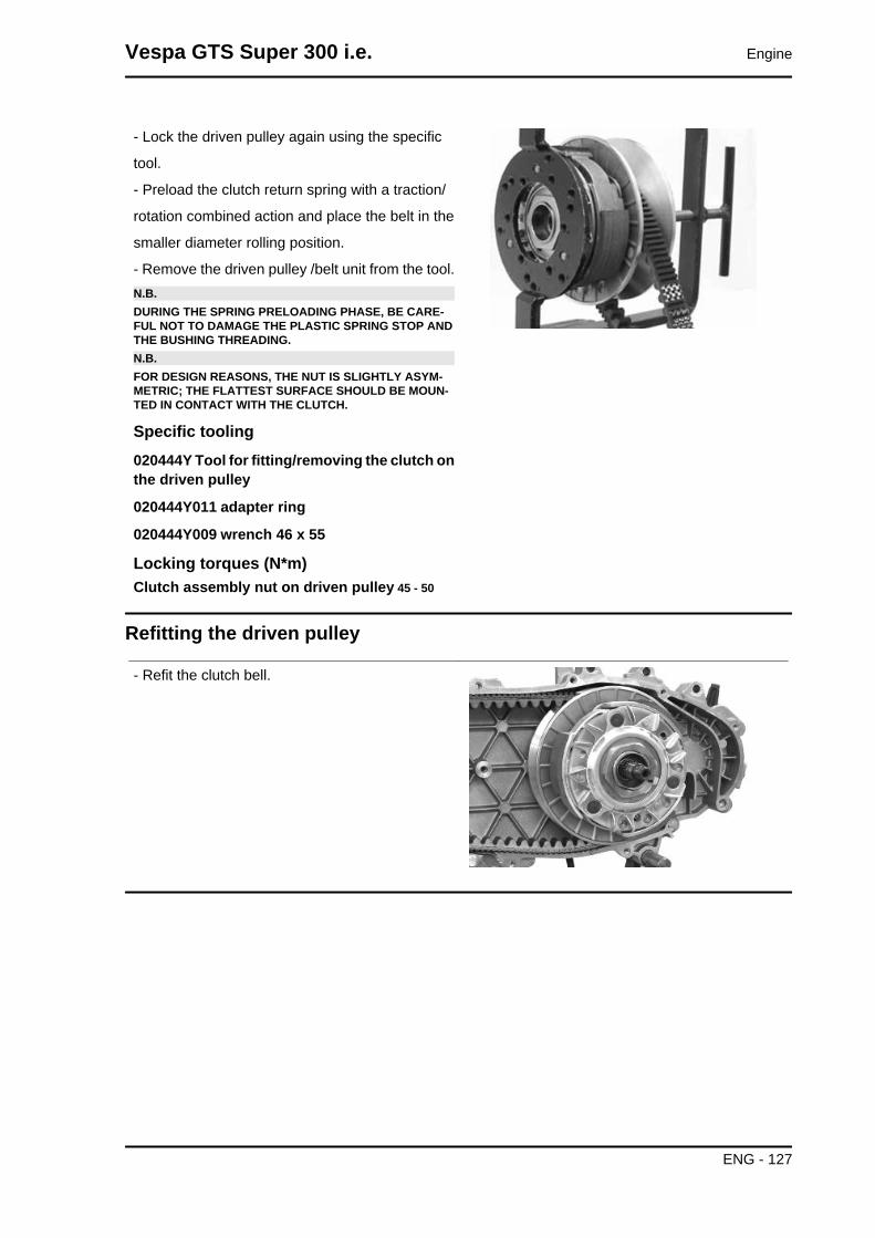
- Lock the driven pulley again using the specific
tool.
- Preload the clutch return spring with a traction/
rotation combined action and place the belt in the
smaller diameter rolling position.
- Remove the driven pulley /belt unit from the tool.N.B.DURING THE SPRING PRELOADING PHASE, BE CARE-FUL NOT TO DAMAGE THE PLASTIC SPRING STOP ANDTHE BUSHING THREADING.N.B.FOR DESIGN REASONS, THE NUT IS SLIGHTLY ASYM-METRIC; THE FLATTEST SURFACE SHOULD BE MOUN-TED IN CONTACT WITH THE CLUTCH.
Specific tooling020444Y Tool for fitting/removing the clutch onthe driven pulley
020444Y011 adapter ring
020444Y009 wrench 46 x 55
Locking torques (N*m)Clutch assembly nut on driven pulley 45 - 50
Refitting the driven pulley
- Refit the clutch bell.
Vespa GTS Super 300 i.e. Engine
ENG - 127

Drive-belt
- Check that the driving belt is not damaged.
- Check the width of the belt.
CharacteristicDriving belt - minimum width19.5 mm
Driving belt - standard width21.3 ± 0.2 mm
During the wear checks in foreseen in the sched-
uled maintenance program, you are advised to
check that the rim bottom of the toothing does not
show signs of incisions or cracking (see figure):
The rim bottom of the tooth must not have incisions
or cracking; if it does, change the belt.
Removing the driving pulley
- Turn the crankshaft until the ropes of the pulley
are on a horizontal axis
- Insert the adaptor sleeve of the appropriate tool
in the hole shown in the picture
Engine Vespa GTS Super 300 i.e.
ENG - 128

- Insert the tool in the hollows and apply the reten-
tion ring
- Bring in the ring's clamping screws while keeping
the tool to support the pulley
Specific tooling020626Y Driving pulley lock wrench
- Remove the fixing nut and the washer
- Remove the stationary drive pulley half.
Inspecting the rollers case
- Check that the internal bushing shown in the fig-
ure is not abnormally worn and measure inner
diameter A.
- Measure outer diameter B of the pulley sliding
bushing shown in the figure.
- Check that the rollers are not damaged or worn.
- Check the guide shoes for the variator back-plate
are not worn.
- Check the wear of the roller housings and of the
belt faying surfaces on both pulley halves.
- Check that stationary driving pulley does not
show signs of abnormal wear on the grooved edge
and on the surface in contact with the belt.
- Check that the O-ring is not pushed out of shape.CAUTIONDO NOT LUBRICATE OR CLEAN SINTERED BUSHINGS
Characteristicmovable driving half-pulley bushing: StandardDiameter26.000 - 26.021 mm
Vespa GTS Super 300 i.e. Engine
ENG - 129

movable driving half-pulley bushing: Maxi-mum allowable diameterØ 26.12 mm
Sliding bushing: Standard DiameterØ 25.959 - 25.98 mm
Sliding bushing: Minimum diameter permittedØ 25.95 mm
Roller: Standard DiameterDiameter 20.5 - 20.7 mm
Roller: Minimum diameter allowedØ 20 mm
Refitting the driving pulley
- Pre-assemble the movable half-pulley with the
roller contrast plate by putting the rollers in their
housings with the larger support surface touching
the pulley according to the direction of rotation.
- Check that the roller contact plate does not have
flaws and is not damaged on the grooved edge.
- Mount the complete bushing unit on the crank-
shaft.
- Fit the driven pulley/Clutch/belt unit on the en-
gine.
Engine Vespa GTS Super 300 i.e.
ENG - 130
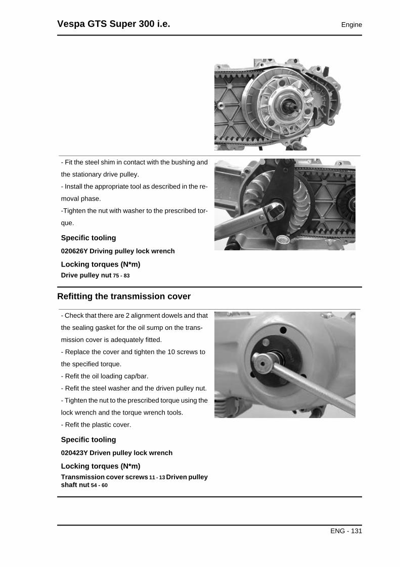
- Fit the steel shim in contact with the bushing and
the stationary drive pulley.
- Install the appropriate tool as described in the re-
moval phase.
-Tighten the nut with washer to the prescribed tor-
que.
Specific tooling020626Y Driving pulley lock wrench
Locking torques (N*m)Drive pulley nut 75 - 83
Refitting the transmission cover
- Check that there are 2 alignment dowels and that
the sealing gasket for the oil sump on the trans-
mission cover is adequately fitted.
- Replace the cover and tighten the 10 screws to
the specified torque.
- Refit the oil loading cap/bar.
- Refit the steel washer and the driven pulley nut.
- Tighten the nut to the prescribed torque using the
lock wrench and the torque wrench tools.
- Refit the plastic cover.
Specific tooling020423Y Driven pulley lock wrench
Locking torques (N*m)Transmission cover screws 11 - 13 Driven pulleyshaft nut 54 - 60
Vespa GTS Super 300 i.e. Engine
ENG - 131

End gear
Removing the hub cover
- Empty the rear hub through the oil drainage plug.
- Remove the 7 flanged screws indicated in the
figure.
- Remove the hub cover and its gasket.
Removing the wheel axle
- Remove the wheel axis complete with gear.
- Remove the intermediate gear.
Engine Vespa GTS Super 300 i.e.
ENG - 132
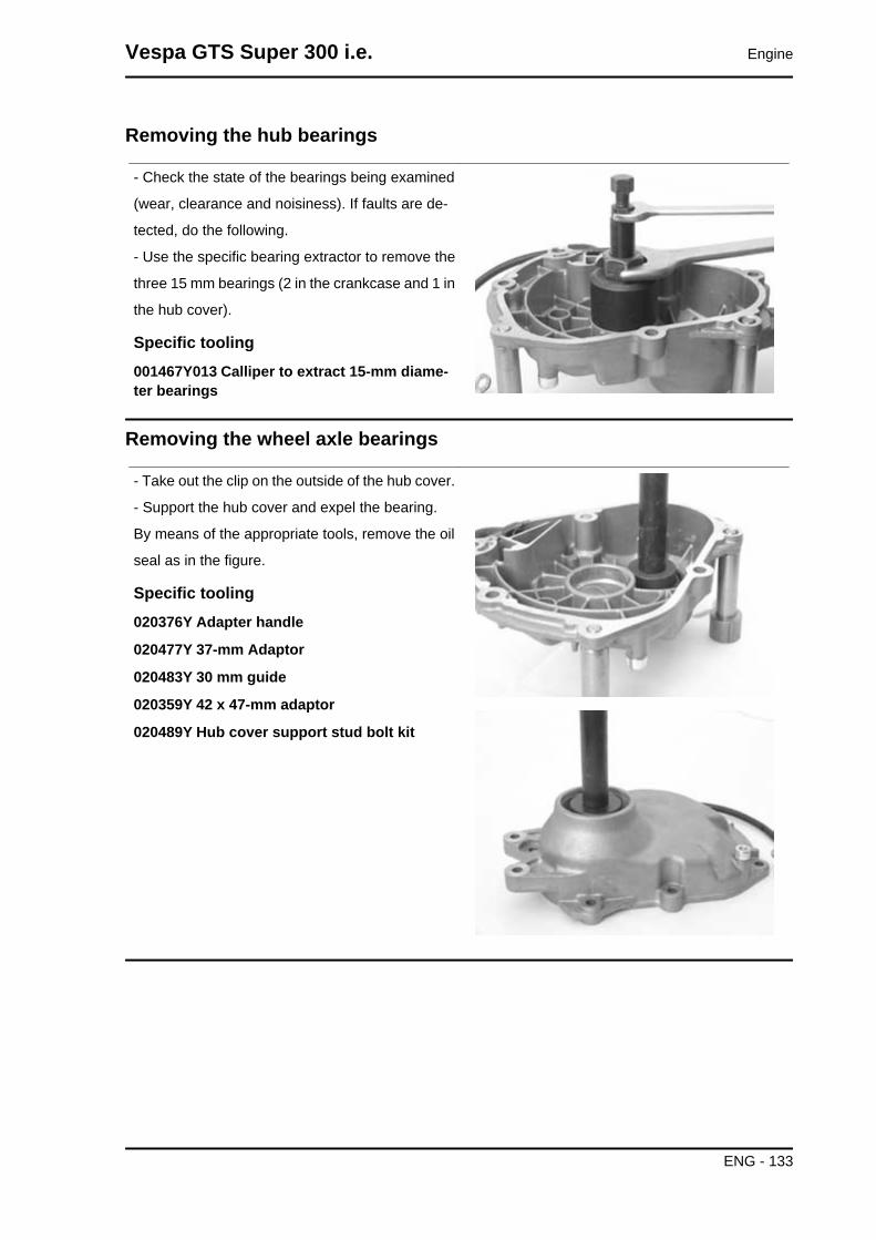
Removing the hub bearings
- Check the state of the bearings being examined
(wear, clearance and noisiness). If faults are de-
tected, do the following.
- Use the specific bearing extractor to remove the
three 15 mm bearings (2 in the crankcase and 1 in
the hub cover).
Specific tooling001467Y013 Calliper to extract 15-mm diame-ter bearings
Removing the wheel axle bearings
- Take out the clip on the outside of the hub cover.
- Support the hub cover and expel the bearing.
By means of the appropriate tools, remove the oil
seal as in the figure.
Specific tooling020376Y Adapter handle
020477Y 37-mm Adaptor
020483Y 30 mm guide
020359Y 42 x 47-mm adaptor
020489Y Hub cover support stud bolt kit
Vespa GTS Super 300 i.e. Engine
ENG - 133

Removing the driven pulley shaft bearing
- As you need to remove the driven pulley shaft, its
bearing and oil seal, remove the transmission cov-
er as described above.
- Extract the driven pulley shaft from its bearing.
- Remove the oil seal using a screwdriver, working
from inside the bearing and being careful not to
damage the housing, make it come out of the belt
transmission side.
- Remove the Seeger ring shown in the figure
- Remove the driven pulley shaft bearing using the
modular punch.
Specific tooling020376Y Adapter handle
020375Y 28 x 30 mm adaptor
020363Y 20 mm guide
Inspecting the hub shaft
- Check the three shafts for wear or distortion of
the toothed surfaces, the bearing housings, and
the oil seal housings.
- If faults are found, replace the damaged compo-
nents.
Inspecting the hub cover
- Check that the fitting surface is not dented or distorted.
- Check the bearing bearings.
- In case of faults, replace the damaged components.
Engine Vespa GTS Super 300 i.e.
ENG - 134
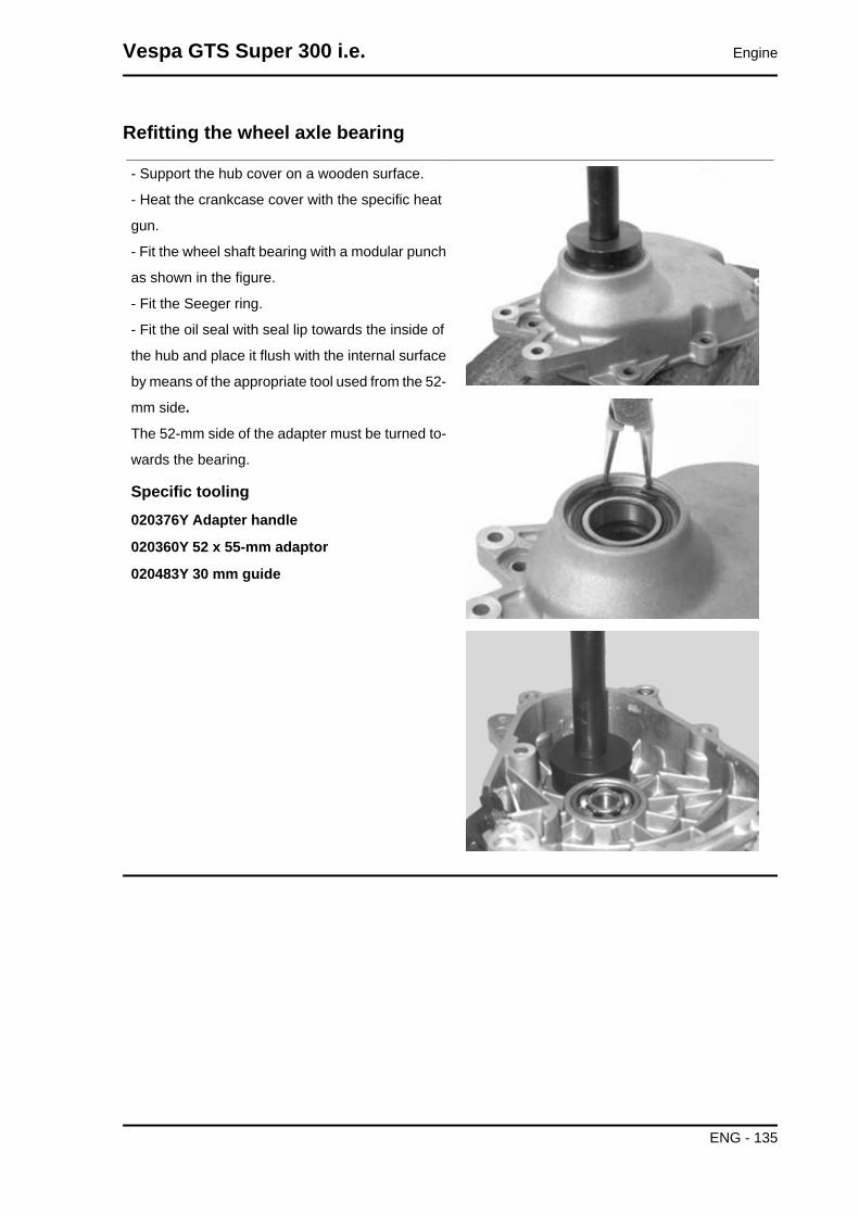
Refitting the wheel axle bearing
- Support the hub cover on a wooden surface.
- Heat the crankcase cover with the specific heat
gun.
- Fit the wheel shaft bearing with a modular punch
as shown in the figure.
- Fit the Seeger ring.
- Fit the oil seal with seal lip towards the inside of
the hub and place it flush with the internal surface
by means of the appropriate tool used from the 52-
mm side.
The 52-mm side of the adapter must be turned to-
wards the bearing.
Specific tooling020376Y Adapter handle
020360Y 52 x 55-mm adaptor
020483Y 30 mm guide
Vespa GTS Super 300 i.e. Engine
ENG - 135

Refitting the hub cover bearings
In order to fit the hub box bearings, the engine
crankcase and the cover must be heated with the
special heat gun.
- The three 15-mm bearings must be fitted using
the appropriate tools:
- The 42-mm side of the adapter must be turned
towards the bearing.
Specific tooling020150Y Air heater support
020151Y Air heater
020376Y Adapter handle
020359Y 42 x 47-mm adaptor
020412Y 15 mm guide
N.B.
TO FIT THE BEARING ON THE COVER, ADEQUATELY SUPPORT THE COVER WITH THE STUDBOLT KIT.
- Refit the driven pulley shaft bearing with a mod-
ular punch as shown in the figure.N.B.IF THE BEARING HAS AN ASYMMETRICAL BALL RETAIN-ER, PLACE IT SO THAT THE BALLS ARE VISIBLE FROMTHE HUB INNER SIDE.
Specific tooling020376Y Adapter handle
020359Y 42 x 47-mm adaptor
020363Y 20 mm guideN.B.
WHEN FITTING THE BEARINGS ON THE ENGINE CRANKCASE, SUPPORT THE CRANKCASEPREFERABLY ON A SURFACE TO ALLOW THE BEARINGS TO BE DRIVEN VERTICALLY.
- Refit the Seeger ring with the opening facing the bearing and fit a new oil seal flush with the crankcase
from the pulley side.
Engine Vespa GTS Super 300 i.e.
ENG - 136

Refitting the hub bearings
- Install the three shafts in the engine crankcase
as shown in the figure.
Refitting the ub cover
- Fit a new gasket together with the alignment
dowels.
- Seal the gasket of the breather pipe using black
silicone sealant.
- Fit the gearbox cover, making sure the breather
pipe is in the correct position.
- Position the shorter screw that can also be rec-
ognised from the different colour as shown in the
figure.
- Fix the breather tube support by means of the
lower screw.
- Fit the remaining screws and tighten the seven
screws to the prescribed torque.
Flywheel cover
Vespa GTS Super 300 i.e. Engine
ENG - 137

Removing the hub cover
- Remove the clip fixing the sleeve to the cylinder.
- Remove the 10 clamps
- Remove the flywheel cover.
Removing the stator
- Remove the two pick-up screws and the screw
holding the wiring support and the three stator
clamping screws shown in the figure.
- Remove the stator and its wiring.
Engine Vespa GTS Super 300 i.e.
ENG - 138
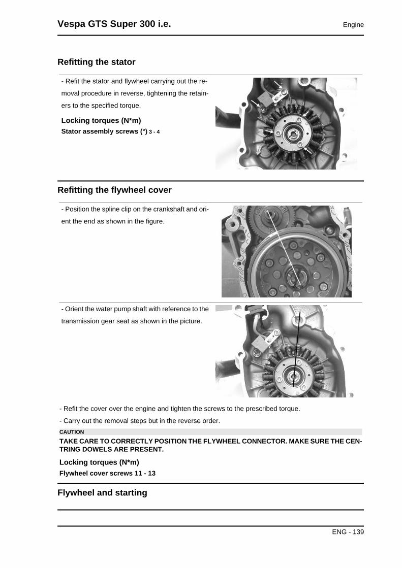
Refitting the stator
- Refit the stator and flywheel carrying out the re-
moval procedure in reverse, tightening the retain-
ers to the specified torque.
Locking torques (N*m)Stator assembly screws (°) 3 - 4
Refitting the flywheel cover
- Position the spline clip on the crankshaft and ori-
ent the end as shown in the figure.
- Orient the water pump shaft with reference to the
transmission gear seat as shown in the picture.
- Refit the cover over the engine and tighten the screws to the prescribed torque.
- Carry out the removal steps but in the reverse order.CAUTION
TAKE CARE TO CORRECTLY POSITION THE FLYWHEEL CONNECTOR. MAKE SURE THE CEN-TRING DOWELS ARE PRESENT.
Locking torques (N*m)Flywheel cover screws 11 - 13
Flywheel and starting
Vespa GTS Super 300 i.e. Engine
ENG - 139

Removing the starter motor
- Remove the two screws indicated in the figure
- Take the starter motor out of its seat
Removing the flywheel magneto
- Remove the water pump shaft and crankshaft
spline clip
- Line up the two holes in the flywheel as shown in
the picture
- Screw in the guide bushing that is part of the
special flywheel stop tool on the flywheel as shown
in the picture
Engine Vespa GTS Super 300 i.e.
ENG - 140

- Insert the special flywheel stop tool on the fly-
wheel as shown in the picture
Specific tooling020627Y Flywheel lock wrench
Remove the plate indicated in the picture.
- Remove the flywheel nut with its washer
- Do up the flywheel nut by three or four threads
so that the flywheel does not fall accidentally on
extraction
- Screw the extractor onto the flywheel and extract
it as shown in the picture
Specific tooling020467Y Flywheel extractor
Inspecting the flywheel components
- Check the integrity of the internal plastic parts of the flywheel and the Pickup control plate.
Refitting the free wheel
- Make sure the freewheel faying surfaces are in good condition.
- Thoroughly clean the free wheel to remove LOCTITE residue.
- Degrease the threading of the holes in the free wheel and the clamping screws.
- Apply the recommended product to the end of the screws.
Recommended productsLoctite 243 Medium strength threadlock
Medium Loctite 243 threadlock
Vespa GTS Super 300 i.e. Engine
ENG - 141

- Fit the freewheel on the magneto flywheel making
sure that the ground side is in contact with the fly-
wheel itself, i.e. with wheel Seeger ring visible.
- Lock the six clamping screws in criss-cross fash-
ion to the prescribed torque.
Locking torques (N*m)Screws fixing freewheel to flywheel 13 to 15
- Oil the free wheel "rollers".
Refitting the flywheel magneto
- Remove the freewheel retaining plate indicated
in the picture
- Remove the transmission gear and the freewheel
- Insert the free wheel on the flywheel as shown in
the picture
- Then refit the flywheel with free wheel and trans-
mission gear
Engine Vespa GTS Super 300 i.e.
ENG - 142

- Using the special flywheel lock wrench, tighten
up the flywheel fixing nut to the prescribed torque
- Refit the retention plate
Specific tooling020627Y Flywheel lock wrench
Locking torques (N*m)Flywheel nut 94 - 102
Refitting the starter motor
- Fit a new O-ring on the starter motor and lubricate
it.
- Fit the starter motor on the crankcase and lock
the 2 screws to the specified torque.
Locking torques (N*m)Starter screws 11 - 13
Cylinder assy. and timing system
Removing the intake manifold
Loosen the 3 screws and remove the air intake manifold.
- Upon refitting, secure to the specified torque.
Vespa GTS Super 300 i.e. Engine
ENG - 143

Removing the rocker-arms cover
- Remove the 5 screws indicated in the figure
Removing the timing system drive
- First remove the parts listed below: transmission
cover, drive pulley with belt, oil sump with spring
and by-pass piston, oil pump pulley cover, O-ring
on the crankshaft and the sprocket wheel separa-
tion washer.
- Remove the tappet cover.
- Remove the central screw fastener and the au-
tomatic valve lifter retaining cover, as shown in the
figure.
- Remove the return spring of the automatic valve
lifter unit and the automatic valve lifter unit and its
end of stroke washer.
Engine Vespa GTS Super 300 i.e.
ENG - 144

- Loosen the central screw on the tensioner first.
- Remove the two fixings shown in the figure.
- Remove the tensioner with its gasket.
- Remove the internal hex screw and the counter-
weight shown in the figure.
- Remove the camshaft control pulley with its
washer.
- Remove the control sprocket wheel and the tim-
ing chain.
- Remove the screws indicated in the figure, the
spacer bar and the tensioner slider.
The tensioner pad must be removed from the
transmission side. As regards the lower chain
guide slider, it may only be removed after the head
has been removed.N.B.IT IS ADVISABLE TO MARK THE CHAIN IN ORDER TO EN-SURE THAT THE INITIAL DIRECTION OF ROTATION ISMAINTAINED.
Vespa GTS Super 300 i.e. Engine
ENG - 145

Removing the cam shaft
- Remove the 2 screws and the camshaft retainer
shown in the diagram.
- Remove the camshaft.
- Remove the pins and the rocking levers from the
flywheel side holes.N.B.IF NEEDED, THE HEAD MAY BE REMOVED WITH THECAMSHAFT, ROCKER PINS AND FIXING BRACKET. THEHEAD CAN ALSO BE REMOVED WITHOUT REMOVINGTHE CHAIN AND THE CRANKSHAFT CHAIN TENSIONER.
Removing the cylinder head
- Remove the spark plug.
- Remove the 2 side fixings shown in the figure.
- Loosen the 4 head-cylinder fastening nuts in two
or three stages and in criss-cross fashion.
- Remove the head, the two alignment dowels and
the gasket.N.B.IF NEEDED, THE HEAD MAY BE REMOVED WITH THECAMSHAFT, ROCKER PINS AND FIXING BRACKET. THEHEAD CAN ALSO BE REMOVED WITHOUT REMOVINGTHE CHAIN AND THE CRANKSHAFT CHAIN TENSIONER.
Engine Vespa GTS Super 300 i.e.
ENG - 146

Removing the valves
- Using the appropriate tool fitted with an adaptor,
remove the cotters, caps, springs and valves.
- Remove the oil guards with the appropriate tool.
- Remove the lower spring supports.CAUTIONREPLACE THE VALVES IN SUCH A WAY AS TO RECOG-NISE THEIR ORIGINAL POSITION ON THE HEAD.
Specific tooling020382Y011 adaptor for valve removing tool
020382Y Tool for removing valve cotters fittedwith part 012
020431Y Valve oil seal extractor
Removing the cylinder - piston assy.
Removing cylinder and piston
- Remove the chain guide slider.
- Remove the 4 O-rings on the stud bolts.
- Pull out the cylinder.
- Remove the cylinder base gasket.
- Remove the two stop rings, the wrist pin and the
piston.
- Remove the piston seals.CAUTIONTO AVOID DAMAGING THE PISTON, SUPPORT IT WHILEREMOVING THE CYLINDER.N.B.BE CAREFUL NOT TO DAMAGE THE SEALING RINGSDURING REMOVAL.
Vespa GTS Super 300 i.e. Engine
ENG - 147
Inspecting the small endN.B.
TO MEASURE WEAR LIMITS AND COUPLING CLEARANCES, SEE THE SPECIFICATIONS CHAP-TER.
See alsoCrankcase - crankshaft - connecting rod
Inspecting the wrist pinN.B.
TO MEASURE WEAR LIMITS AND COUPLING CLEARANCES, SEE THE SPECIFICATIONS CHAP-TER.
See alsoCylinder - piston assy.
Inspecting the pistonN.B.
TO MEASURE WEAR LIMITS AND COUPLING CLEARANCES, SEE THE SPECIFICATIONS CHAP-TER.
See alsoCylinder - piston assy.
Inspecting the cylinderN.B.
TO MEASURE WEAR LIMITS AND COUPLING CLEARANCES, SEE THE SPECIFICATIONS CHAP-TER.
See alsoCylinder - piston assy.
Inspecting the piston ringsN.B.
TO MEASURE WEAR LIMITS AND COUPLING CLEARANCES, SEE THE SPECIFICATIONS CHAP-TER.
See alsoPiston rings
Engine Vespa GTS Super 300 i.e.
ENG - 148

Removing the piston
- Install piston and wrist pin onto the connecting
rod, aligning the piston arrow the arrow facing to-
wards the exhaust.
- Fit the wrist pin retainer ring onto the appropriate
tool
- With opening in the position indicated on the tool
S = left
D= right
- Place the wrist pin retainer ring into position using
a punch
- Fit the wrist pin snap ring using the plug as shown
in the figureN.B.THE TOOL FOR INSTALLING THE RETAINER RINGS MUSTBE USED MANUALLY.CAUTIONUSING A HAMMER MIGHT DAMAGE THE STOPS' HOUS-ING.
Specific tooling020454Y Pin lock fitting tool
Choosing the gasket
- Provisionally fit the piston into the cylinder, without any base gasket.
- Assemble a dial gauge on the specific tool.
Specific tooling020428Y Support to check piston position
- With a contrasting surface, reset the dial gauge
with a preloading of a few millimetres.
- Finally fix the dial gauge.
- Check the perfect sliding of the feeler pin.
- Fit the tool on the cylinder without changing the
dial gauge position.
- Lock the tool with the original head fixing nuts.
- Rotate the crankshaft up to TDC (the reversal
point of the dial gauge rotation).
- Measure the deviation from the reset value.
Vespa GTS Super 300 i.e. Engine
ENG - 149
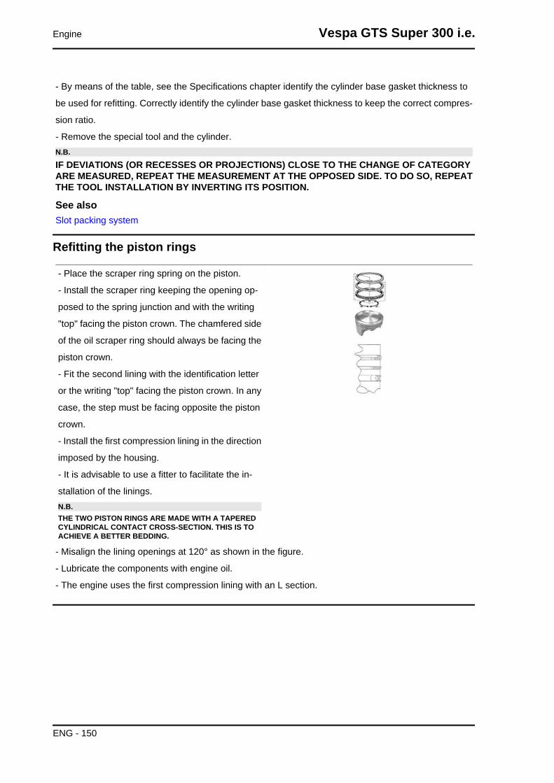
- By means of the table, see the Specifications chapter identify the cylinder base gasket thickness to
be used for refitting. Correctly identify the cylinder base gasket thickness to keep the correct compres-
sion ratio.
- Remove the special tool and the cylinder.N.B.
IF DEVIATIONS (OR RECESSES OR PROJECTIONS) CLOSE TO THE CHANGE OF CATEGORYARE MEASURED, REPEAT THE MEASUREMENT AT THE OPPOSED SIDE. TO DO SO, REPEATTHE TOOL INSTALLATION BY INVERTING ITS POSITION.
See alsoSlot packing system
Refitting the piston rings
- Place the scraper ring spring on the piston.
- Install the scraper ring keeping the opening op-
posed to the spring junction and with the writing
"top" facing the piston crown. The chamfered side
of the oil scraper ring should always be facing the
piston crown.
- Fit the second lining with the identification letter
or the writing "top" facing the piston crown. In any
case, the step must be facing opposite the piston
crown.
- Install the first compression lining in the direction
imposed by the housing.
- It is advisable to use a fitter to facilitate the in-
stallation of the linings.N.B.THE TWO PISTON RINGS ARE MADE WITH A TAPEREDCYLINDRICAL CONTACT CROSS-SECTION. THIS IS TOACHIEVE A BETTER BEDDING.
- Misalign the lining openings at 120° as shown in the figure.
- Lubricate the components with engine oil.
- The engine uses the first compression lining with an L section.
Engine Vespa GTS Super 300 i.e.
ENG - 150

Refitting the cylinder
- Insert the cylinder base gasket with the thickness
determined above.
- Using the fork support and the piston ring retain-
ing band, refit the cylinder as shown in the figure.N.B.BEFORE FITTING THE CYLINDER, CAREFULLY BLOWOUT THE LUBRICATION DUCT AND OIL THE CYLINDERBARREL.
Specific tooling020426Y Piston fitting fork
020393Y Piston fitting ring
Inspecting the cylinder headN.B.
TO MEASURE WEAR LIMITS AND COUPLING CLEARANCES, SEE THE SPECIFICATIONS CHAP-TER.
See alsoCylinder Head
Inspecting the timing system components
- Check that the guide slider and the tensioner pad
are not excessively worn.
- Ensure that the camshaft control pulley chain as-
sembly and the sprocket wheel are not worn.
- If you detect wear, replace the parts or, if the
chain, sprocket wheel and pulley are worn, replace
the whole unit.
- Remove the centre screw with the washer and
the tensioner spring. Check that the one-way
mechanism is not worn.
- Check the condition of the tensioner spring.
- If signs of wear are found, replace the whole as-
sembly.
Vespa GTS Super 300 i.e. Engine
ENG - 151

Inspecting the valve sealingsN.B.
TO MEASURE WEAR LIMITS AND COUPLING CLEARANCES, SEE THE SPECIFICATIONS CHAP-TER.
See alsoCylinder Head
Inspecting the valvesN.B.
TO MEASURE WEAR LIMITS AND COUPLING CLEARANCES, SEE THE SPECIFICATIONS CHAP-TER.
See alsoCylinder Head
Inspecting the springs and half-cones
- Check that the upper and lower supporting spring
washers, the cotters and the oil seal show exhibit
no signs of abnormal wear. Replace a component
when worn.
- Measure the unloaded spring length.N.B.
TO MEASURE WEAR LIMITS AND COUPLING CLEARANCES, SEE THE SPECIFICATIONS CHAP-TER.
See alsoCylinder Head
Refitting the valves
- Lubricate the valve guides with engine oil.
- Place the valve spring supports on the head.
- Using the special punch, fit the four valve seal
rings.
- Fit the valves, the springs and the caps. Using
the appropriate tool with adapter, compress the
springs and insert the cotters in their seats.N.B.
Engine Vespa GTS Super 300 i.e.
ENG - 152
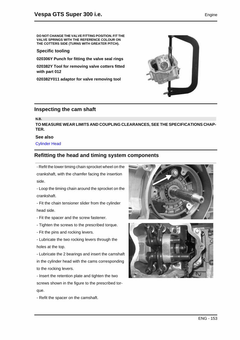
DO NOT CHANGE THE VALVE FITTING POSITION. FIT THEVALVE SPRINGS WITH THE REFERENCE COLOUR ONTHE COTTERS SIDE (TURNS WITH GREATER PITCH).
Specific tooling020306Y Punch for fitting the valve seal rings
020382Y Tool for removing valve cotters fittedwith part 012
020382Y011 adaptor for valve removing tool
Inspecting the cam shaftN.B.
TO MEASURE WEAR LIMITS AND COUPLING CLEARANCES, SEE THE SPECIFICATIONS CHAP-TER.
See alsoCylinder Head
Refitting the head and timing system components
- Refit the lower timing chain sprocket wheel on the
crankshaft, with the chamfer facing the insertion
side.
- Loop the timing chain around the sprocket on the
crankshaft.
- Fit the chain tensioner slider from the cylinder
head side.
- Fit the spacer and the screw fastener.
- Tighten the screws to the prescribed torque.
- Fit the pins and rocking levers.
- Lubricate the two rocking levers through the
holes at the top.
- Lubricate the 2 bearings and insert the camshaft
in the cylinder head with the cams corresponding
to the rocking levers.
- Insert the retention plate and tighten the two
screws shown in the figure to the prescribed tor-
que.
- Refit the spacer on the camshaft.
Vespa GTS Super 300 i.e. Engine
ENG - 153

- Rotate the engine so that the piston is at top dead
centre, using the reference marks on the flywheel
and the crankcase.
- Holding this position insert the chain on the cam-
shaft control pulley.
- Insert the pulley on the camshaft while keeping
the reference 4V in correspondence with the ref-
erence mark on the head.
- Fit the counterweight and tighten the clamping
screw to the prescribed torque.
-Fit the end-stop ring on the automatic valve-lifter
cam and fit the automatic valve-lifter cam to the
camshaft.
- Fit the automatic valve lifter return spring.
- During this operation the spring must be loaded
by approximately 180°.
- Fit the automatic valve-lifter retaining dish, using
the counterweight screw fastener as a reference.
- Tighten the clamping screw to the prescribed tor-
que.
- Set the tensioner cursor in the rest position.
- Fit the chain tensioner on the cylinder, using a
new gasket, and tight the two screws to the speci-
fied torque.
- Insert the chain tensioning screw, together with
the spring and washer, tightening it to the specified
torque.
- Adjust the valve clearance.
- Fit the spark plug.
Electrode distance 0.8 mmN.B.GREASE THE END STOP RING TO PREVENT IT COMINGOUT AND FALLING INTO THE ENGINE.
Locking torques (N*m)Timing chain tensioner support screw 11 - 13Spark plug 12 - 14 Starter ground screw 7 - 8.5Timing chain tensioner slider screw 10 to 14Starter ground bell screw 11 to 15 Timing chaintensioner central screw 5 - 6 Camshaft retentionplate screw 4 - 6
Engine Vespa GTS Super 300 i.e.
ENG - 154

- Fit the timing chain guide slider.
- Insert the centring dowel between the cylinder
head to the cylinder, fit the cylinder head gasket
and the cylinder head.
- Lubricate the stud bolt threading.
- Tighten up the nuts to an initial pre-torque of 7±1
N·m
- Tighten up the nuts to a second pre-torque of 10
±1 N·m
- Rotate by an angle of 270°
- To carry out the operations described above, fol-
low the tightening sequence in the figure.
Vespa GTS Super 300 i.e. Engine
ENG - 155
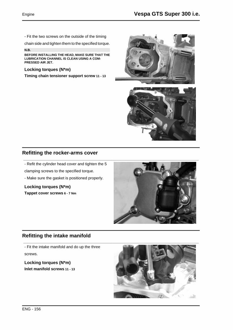
- Fit the two screws on the outside of the timing
chain side and tighten them to the specified torque.N.B.BEFORE INSTALLING THE HEAD, MAKE SURE THAT THELUBRICATION CHANNEL IS CLEAN USING A COM-PRESSED AIR JET.
Locking torques (N*m)Timing chain tensioner support screw 11 - 13
Refitting the rocker-arms cover
- Refit the cylinder head cover and tighten the 5
clamping screws to the specified torque.
- Make sure the gasket is positioned properly.
Locking torques (N*m)Tappet cover screws 6 - 7 Nm
Refitting the intake manifold
- Fit the intake manifold and do up the three
screws.
Locking torques (N*m)Inlet manifold screws 11 - 13
Engine Vespa GTS Super 300 i.e.
ENG - 156

Crankcase - crankshaft
Splitting the crankcase halves
- Before opening the crankcase, it is advisable to
check the axial clearance of the crankshaft. To do
this, use a plate and a support with appropriate tool
dial gauge.
- Upper clearances are an indication of wear on
the surfaces of the crankshaft casing support.
- Remove the 10 crankshaft coupling screws.
- Separate the crankcase while keeping the crank-
shaft in one of the two halves of the crankcase.
- Remove the crankshaft.
- Remove the half crankcase coupling gasket.
- Remove the two screws and the internal cover
shown in the diagram.
- Remove the oil guard on the flywheel side.
- Remove the oil filter fitting shown in the diagram.
- Check the axial clearance on the connecting rod.
- Check the radial clearance on the connecting rod.
-Check the surfaces that limit the axial free-play
are not scored and measure the width of the crank-
shaft between these surfaces, as shown in the
diagram.
- If the axial clearance between crankshaft and
crankcase is exceeding and the crankshaft does
not have any defect, the problem must be due to
either excessive wear or wrong machining on the
crankcase.
- Check the diameters of both the bearings of the
crankshaft in accordance with the axes and surfa-
ces shown in the figure. The half-shafts are clas-
sified in two categories Cat. 1 and Cat. 2 as shown
the chart below.CAUTIONTHE CRANKSHAFT CAN BE REUSED WHEN THE WIDTHIS WITHIN THE STANDARD VALUES AND THE SURFACESSHOW NO SIGNS OF SCORING.
Vespa GTS Super 300 i.e. Engine
ENG - 157

CAUTIONWHILE OPENING THE CRANKCASES AND REMOVINGTHE CRANKSHAFT, CHECK THAT THE THREADEDSHAFT ENDS DO NOT INTERFERE WITH THE MAIN BUSH-INGS. FAILURE TO OBSERVE THIS PRECAUTION CANDAMAGE THE MAIN BUSHINGS.CAUTION
KEEP THE CRANKSHAFT IN ONE OF THE TWO HALVESOF THE CRANKCASE WHEN SEPARATING IT. IF YOU FAILTO DO THIS, THE CRANKSHAFT MIGHT ACCIDENTALLYFALL.N.B.WHEN MEASURING THE WIDTH OF THE CRANKSHAFT,MAKE SURE THAT THE MEASUREMENTS ARE NOTMODIFIED BY THE RADII OF FITTINGS WITH THE CRANK-SHAFT BEARINGS.N.B.TO MEASURE WEAR LIMITS AND COUPLING CLEARAN-CES, SEE THE SPECIFICATIONS CHAPTER.
See alsoCrankcase - crankshaft - connecting rod
Inspecting the crankshaft alignmentN.B.
TO MEASURE WEAR LIMITS AND COUPLING CLEARANCES, SEE THE SPECIFICATIONS CHAP-TER.
See alsoCrankcase - crankshaft - connecting rod
Inspecting the crankcase halves
- Before proceeding to check the crankcase
halves, thoroughly clean all surfaces and oil ducts.
- On the transmission-side crankcase half, take
particular care when handling the oil pump com-
partment and the oil ducts, the by-pass duct, the
main bushings and the cooling jet on the trans-
mission side (see diagram).
- Take particular care, also, that there are no signs
wear in the oil by-pass valve housing (see Chapter
Lubrication), as this could prevent a good seal in
the piston, which regulates the oil pressure.
- On the flywheel side crankcase half, take partic-
ular care cleaning the oil ducts for the main bush-
ings, the oil duct for the jet that lubricates the
Engine Vespa GTS Super 300 i.e.
ENG - 158

cylinder head and the oil drainage duct at the fly-
wheel side oil seal.
- Inspect the coupling surfaces on the crankcase
halves for scratches or deformation, taking partic-
ular care with the cylinder/crankcase surfaces and
the crankcase halves surfaces.
- Defects in the crankcase coupling gasket be-
tween the crankcase halves or the mating surfaces
shown in the diagram, could cause a drop in the
oil pressure lubricating the main bushings and
connecting rod.
- Check the main bearing seats that limit axial
clearance in the crankshaft show no signs of wear.
The dimension between these seats is measured
by way of the procedure described previously for
measuring the crankshaft axial clearance and di-
mensions.N.B.THE JET IS FED THROUGH THE MAIN BUSHINGS. PROP-ER OPERATION OF THIS COMPONENT IMPROVES PIS-TON CROWN COOLING. CLOGGING HAS EFFECTS THATARE DIFFICULT TO DETECT (PISTON TEMPERATURE IN-CREASE). FAILURE OR LEAKS CAN CAUSE A CONSID-ERABLE DROP IN THE LUBRICATION PRESSURE FORMAIN BUSHINGS AND CONNECTING ROD.N.B.THE HEAD LUBRICATION CHANNEL IS PROVIDED WITHA SHUTTER JET; THIS GIVES A "LOW PRESSURE" HEADLUBRICATION; THIS CHOICE WAS MADE TO REDUCETHE OIL TEMPERATURE IN THE SUMP. THE JET CLOG-GING IMPAIRS THE HEAD LUBRICATION AND THE TIM-ING MECHANISMS. A JET FAILURE CAUSES A DE-CREASE OF THE MAIN BUSHING AND CONNECTING RODLUBRICATION PRESSURE.
Inspecting the crankshaft plain bearings
- To obtain a good bushing lubrication it is necessary to have both an optimal lubricating pressure and
a good oil flow rate; the bushings must be correctly positioned so as not to obstruct the oil supply
channels.
- The main bushings are comprised of two half-bearings, one with holes and channels for lubrication
whereas the other is solid.
CharacteristicLubrication pressure
3.5 to 4 bar
Vespa GTS Super 300 i.e. Engine
ENG - 159

- The solid half-bearing is intended to stand the
thrusts caused by combustion, and for this reason
it is arranged opposed the cylinder.
- To prevent shutters in the oil feeding channels,
the matching surface of the two half-bearings must
be perfectly orthogonal to the cylinder axis, as
shown in the figure.
- The oil feeding channel section is also affected
by the bushings driving depth compared with the
crankshaft axial clearance of the limiting surface.N.B.
TO MEASURE WEAR LIMITS AND COUPLING CLEARANCES, SEE THE SPECIFICATIONS CHAP-TER.
See alsoCrankcase - crankshaft - connecting rod
Refitting the crankcase halves
- Fit the internal shield by locking the two screws
to the prescribed torque.
- Fit the oil filter fitting and tighten it to the prescri-
bed torque.
- Position the oil pre-filter element as shown in the
picture.
- Place a new gasket on one of the crankcase
halves, preferably on the transmission side, to-
gether with the alignment dowels.
- Lubricate the main bushings and insert the crank-
shaft in the transmission side crankcase half.
- Reassemble both crankcase halves.
- Fit the 10 screws and tighten them to the speci-
fied torque.
- Fit a new O-ring on the pre-filter and lubricate it.
- Insert the filter on the engine with the relative cap.
Tighten to the prescribed torque.
Locking torques (N*m)Internal engine crankcase bulkhead (transmis-sion-side half shaft) screws 4 - 6 Engine crank-case coupling screws 11 - 13 Oil filter oncrankcase fitting 27 - 33 Engine oil drainageplug/ mesh filter 24 to 30
Engine Vespa GTS Super 300 i.e.
ENG - 160

Studs
Check that the stud bolts have not worked loose
from their seat in the crankcase.
Check the depth of stud bolt driving with a gauge,
as indicated in the picture. If it varies significantly
from the driving depth indicated, it means that the
stud bolt has yielded.
In this case, replace it.
Vespa GTS Super 300 i.e. Engine
ENG - 161
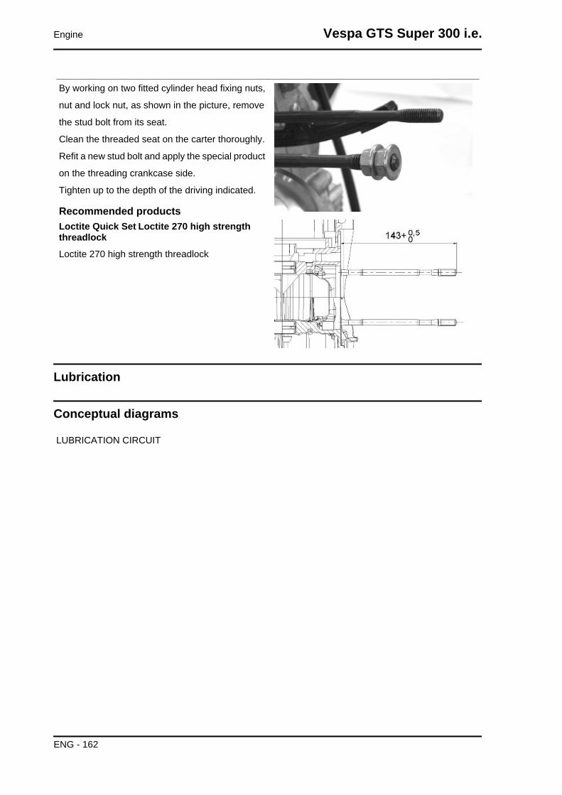
By working on two fitted cylinder head fixing nuts,
nut and lock nut, as shown in the picture, remove
the stud bolt from its seat.
Clean the threaded seat on the carter thoroughly.
Refit a new stud bolt and apply the special product
on the threading crankcase side.
Tighten up to the depth of the driving indicated.
Recommended productsLoctite Quick Set Loctite 270 high strengththreadlockLoctite 270 high strength threadlock
Lubrication
Conceptual diagrams
LUBRICATION CIRCUIT
Engine Vespa GTS Super 300 i.e.
ENG - 162

Vespa GTS Super 300 i.e. Engine
ENG - 163

Oil pressure check
- Remove the electrical minimum oil pressure
switch connection and remove the switch.
- Check that the oil pressure reading is between
0.5 and 1.2 atm with the engine idling at 1650 rpm
and the oil at the required temperature (wait for at
least one electric ventilation).
- Check that the oil pressure is between 3.2 and
4.2 atm with the engine running at 6000 rpm and
the oil at the required temperature.
- Remove the appropriate tools once the meas-
urement is complete, refit the oil pressure switch
and washer, tightening it to the specified torque
and fit the flywheel cover.
- If the oil pressure is not within the specified limits,
in the following order, check: the oil filter, the oil
by-pass valve, the oil pump and the crankshaft
seals.N.B.THE CHECK MUST BE CARRIED OUT WITH OIL AT THECORRECT LEVEL AND WITH AN OIL FILTER IN PROPERCONDITION.
CharacteristicOil pressureMinimum pressure admitted at 6,000 rpm: 3.2 atm.
Locking torques (N*m)Minimum oil pressure sensor 12 - 14
Crankshaft oil seals
Engine Vespa GTS Super 300 i.e.
ENG - 164

Removal
- Remove the transmission cover and the com-
plete drive pulley beforehand
- Install the base of the appropriate tool on the oil
seal using the screws provided.
Specific tooling020622Y Transmission-side oil seal punch
- Screw the threaded bar onto the base of the tool
and extract the oil seal.
Specific tooling020622Y Transmission-side oil seal punch
Refitting
- Always use a new oil seal upon refitting
- Prepare the new oil guard by lubricating the seal-
ing lip.
- Preassemble the oil seal with the appropriate tool
by positioning the screws.
- Insert the sheath over the crankshaft.
- Insert the tool with the oil seal on the crankshaft
until it comes into contact with the crankcase.
- Insert the adaptor bushing of the tool in the hole
on the crankcase.
Vespa GTS Super 300 i.e. Engine
ENG - 165

- Orientate the oil seal by inserting the bracket
which is part of the appropriate tool.
- Tighten the threaded bar onto the crankshaft as
far as it will go.
- Use the nut to move the base of the tool until you
can see the end of the oil seal driving stroke
- Remove all the tool components following the
procedure but in reverse orderCAUTIONDO NOT LUBRICATE THE KEYING SURFACE ONTO THEENGINE CRANKCASE.CAUTIONORIENT THE OIL SEAL BY POSITIONING THE CHAINHOUSING CHANNEL FACING DOWNWARDS. WHEN THEPOSITION IS REACHED, DO NOT RETRACT THE OILSEAL. FAILURE TO COMPLY WITH THIS RULE CANCAUSE A WRONG POSITIONING OF THE OIL SEALSHEATH.CAUTIONFAILURE TO COMPLY WITH THIS ASSEMBLY PROCE-DURE CAN SERIOUSLY DAMAGE THE ENGINE DUE TOTHE WRONG TENSIONING OF THE OIL PUMP CONTROLCHAIN.
Specific tooling020622Y Transmission-side oil seal punch
Oil pump
Engine Vespa GTS Super 300 i.e.
ENG - 166
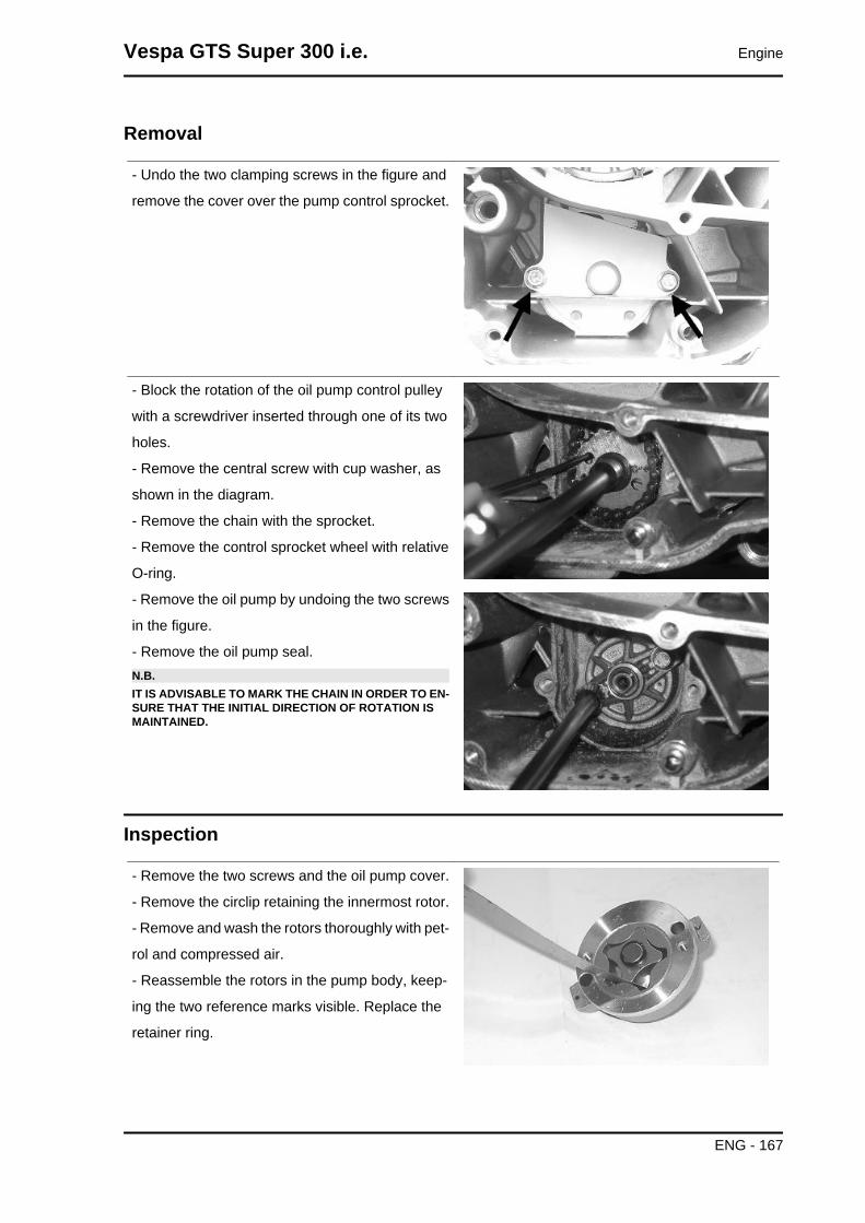
Removal
- Undo the two clamping screws in the figure and
remove the cover over the pump control sprocket.
- Block the rotation of the oil pump control pulley
with a screwdriver inserted through one of its two
holes.
- Remove the central screw with cup washer, as
shown in the diagram.
- Remove the chain with the sprocket.
- Remove the control sprocket wheel with relative
O-ring.
- Remove the oil pump by undoing the two screws
in the figure.
- Remove the oil pump seal.N.B.IT IS ADVISABLE TO MARK THE CHAIN IN ORDER TO EN-SURE THAT THE INITIAL DIRECTION OF ROTATION ISMAINTAINED.
Inspection
- Remove the two screws and the oil pump cover.
- Remove the circlip retaining the innermost rotor.
- Remove and wash the rotors thoroughly with pet-
rol and compressed air.
- Reassemble the rotors in the pump body, keep-
ing the two reference marks visible. Replace the
retainer ring.
Vespa GTS Super 300 i.e. Engine
ENG - 167
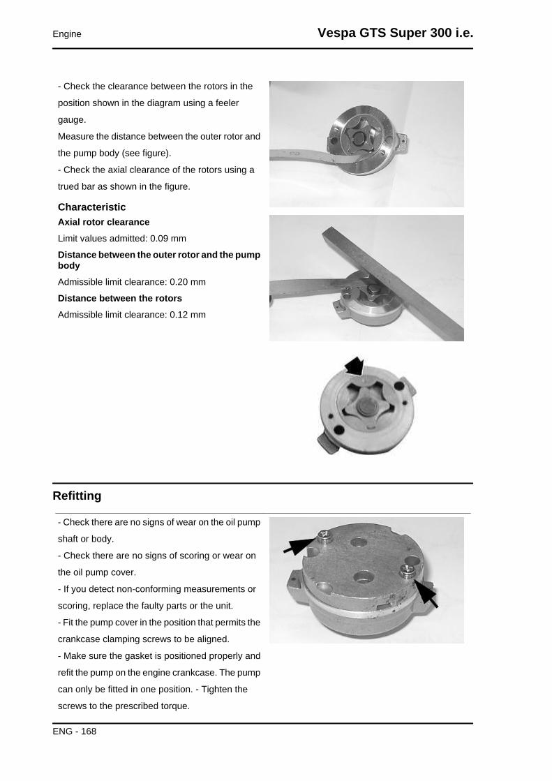
- Check the clearance between the rotors in the
position shown in the diagram using a feeler
gauge.
Measure the distance between the outer rotor and
the pump body (see figure).
- Check the axial clearance of the rotors using a
trued bar as shown in the figure.
CharacteristicAxial rotor clearanceLimit values admitted: 0.09 mm
Distance between the outer rotor and the pumpbodyAdmissible limit clearance: 0.20 mm
Distance between the rotorsAdmissible limit clearance: 0.12 mm
Refitting
- Check there are no signs of wear on the oil pump
shaft or body.
- Check there are no signs of scoring or wear on
the oil pump cover.
- If you detect non-conforming measurements or
scoring, replace the faulty parts or the unit.
- Fit the pump cover in the position that permits the
crankcase clamping screws to be aligned.
- Make sure the gasket is positioned properly and
refit the pump on the engine crankcase. The pump
can only be fitted in one position. - Tighten the
screws to the prescribed torque.
Engine Vespa GTS Super 300 i.e.
ENG - 168

- Fit the sprocket wheel with a new O-ring.
- Fit the chain.
- Fit the central screw and the cup washer. Tighten
to the prescribed torque.
-Fit the oil pump cover, by tightening the two
screws to the prescribed torque.N.B.FIT THE BELLEVILLE WASHER SO THAT ITS OUTER RIMTOUCHES THE PULLEY. MAKE SURE THAT THE PUMPTURNS FREELY.
Locking torques (N*m)Screws fixing oil pump to crankcase 5 - 6 Oilpump command sprocket screw 10 to 14 Oilpump cover screws 0.7 ÷ 0.9
Removing the oil sump
- Remove the oil filler plug, the transmission cover,
the complete driving pulley assembly with belt and
the sprocket wheel, as described in the "Trans-
mission" chapter.
- Drain the oil as described above.
- Remove the 7 screws, shown in the diagram, and
the 2 rear brake fluid pipe fixing brackets.
- Remove the screw, the by-pass piston, the gas-
ket and the centring dowels shown in the figure.
Vespa GTS Super 300 i.e. Engine
ENG - 169

Inspecting the by-pass valve
- Check the unloaded spring length.
- Check that the small piston is not scored.
- Ensure that it slides freely on the crankcase and
that it guarantees a good seal.
- If not, eliminate any impurities or replace defec-
tive parts.
CharacteristicBy-pass check up: Standard length54.2 mm
Refitting the oil sump
- Refit the by-pass piston in its housing.
- Insert the pressure-regulating spring.
- Fit a new sump seal.
- Refit the two centring dowels.
- Refit the sump, taking care to locate the spring in
the appropriate recess machined into the inside of
the sump.
- Refit the rear brake cable brackets and the
screws in the reverse order from which they were
removed.
- Tighten the screws to the prescribed torque.
- Refit the driving pulley assembly, the drive belt,
the sprocket wheel and the transmission cover, as
described in the "Transmission" chapter.
- When testing the lubrication system, refer to
chapter "Crankcase and Crankshaft", regard-
ing lubrication of the crankshaft and connect-
ing rod
Locking torques (N*m)Oil sump screws 10 to 14
Engine Vespa GTS Super 300 i.e.
ENG - 170

INDEX OF TOPICS
INJECTION INJEC

MIU injection system
This vehicle is fitted with an integrated injection and ignition system.
Injection is indirect in the manifold through an electro-injector.
The injection and ignition are timed on the four-stroke cycle by means of a tone wheel keyed on to the
crankshaft (24-2 teeth) and pick-up sensor.
Combustion and ignition are managed on the basis of engine revs and throttle valve opening. Further
corrections are made according to the following parameters:
- Coolant temperature
- Intake air temperature
- Lambda probe
The system implements cold engine idle fuel/air mixture correction with a stepper motor on a by-pass
circuit of the throttle valve. The control unit manages the Stepper motor and the injector opening time,
thereby ensuring the idle steadiness and the proper combustion.
In all conditions of use, mixture preparation is managed by modifying the injector opening time.
The fuel system pressure is kept constant in relation to ambient pressure.
The fuel supply circuit consists of:
- Fuel pump
- Fuel filter
- Injector
- Pressure regulator
Pump, filter and regulator are placed into the fuel tank using a single support.
The injector is connected by a pipe with fast-release fittings. The pressure regulator is located at the
beginning of the circuit.
The fuel pump is controlled by the MIU control unit; therefore the vehicle's safety is enhanced.
The ignition circuit consists of:
- HV coil
- HV cable
- Shielded cap
- MIU control unit
- Spark plug
The MIU control unit manages the ignition with the best advance ensuring 4-stroke timing (ignition only
in the compression stroke) at the same time.
The MIU injection-ignition system controls engine functions by means of a pre-set program.
Should any input signals fail, an acceptable working order of the engine is ensured to allow the user to
reach a service station.
Obviously, this cannot happen when the rev counter signal is missing, or when the failure concerns the
control circuits:
- Fuel pump
Injection Vespa GTS Super 300 i.e.
INJEC - 172
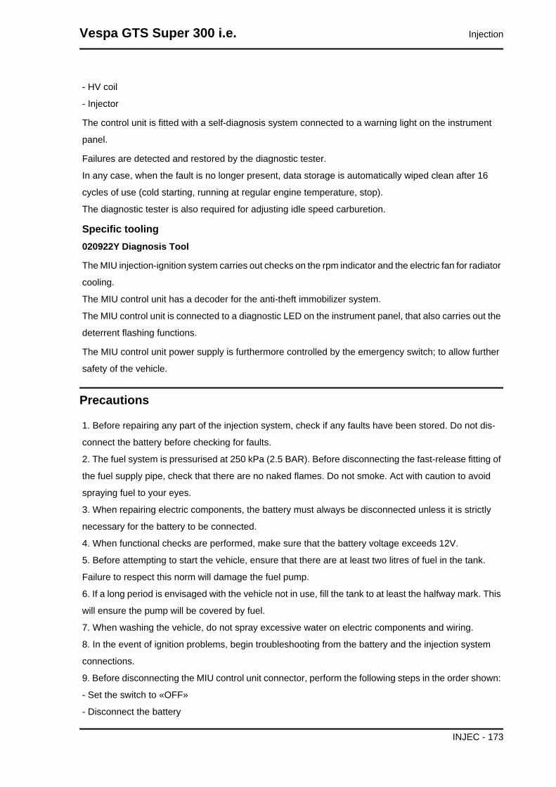
- HV coil
- Injector
The control unit is fitted with a self-diagnosis system connected to a warning light on the instrument
panel.
Failures are detected and restored by the diagnostic tester.
In any case, when the fault is no longer present, data storage is automatically wiped clean after 16
cycles of use (cold starting, running at regular engine temperature, stop).
The diagnostic tester is also required for adjusting idle speed carburetion.
Specific tooling020922Y Diagnosis Tool
The MIU injection-ignition system carries out checks on the rpm indicator and the electric fan for radiator
cooling.
The MIU control unit has a decoder for the anti-theft immobilizer system.
The MIU control unit is connected to a diagnostic LED on the instrument panel, that also carries out the
deterrent flashing functions.
The MIU control unit power supply is furthermore controlled by the emergency switch; to allow further
safety of the vehicle.
Precautions
1. Before repairing any part of the injection system, check if any faults have been stored. Do not dis-
connect the battery before checking for faults.
2. The fuel system is pressurised at 250 kPa (2.5 BAR). Before disconnecting the fast-release fitting of
the fuel supply pipe, check that there are no naked flames. Do not smoke. Act with caution to avoid
spraying fuel to your eyes.
3. When repairing electric components, the battery must always be disconnected unless it is strictly
necessary for the battery to be connected.
4. When functional checks are performed, make sure that the battery voltage exceeds 12V.
5. Before attempting to start the vehicle, ensure that there are at least two litres of fuel in the tank.
Failure to respect this norm will damage the fuel pump.
6. If a long period is envisaged with the vehicle not in use, fill the tank to at least the halfway mark. This
will ensure the pump will be covered by fuel.
7. When washing the vehicle, do not spray excessive water on electric components and wiring.
8. In the event of ignition problems, begin troubleshooting from the battery and the injection system
connections.
9. Before disconnecting the MIU control unit connector, perform the following steps in the order shown:
- Set the switch to «OFF»
- Disconnect the battery
Vespa GTS Super 300 i.e. Injection
INJEC - 173

Failure to respect this norm may damage the control unit.
10. Do not invert the poles when fitting the battery.
11. In order to not cause damage, disconnect and reconnect the connectors of the MIU system only
after proven necessary. Before reconnecting, check that the connectors are dry.
12. When carrying out electric inspections, do not force the tester probes into the connectors. Do not
take measurements not specifically foreseen by the manual.
13. At the end of every check performed with the diagnostic tester, remember to protect the system
connector with its cap. Failure to observe this precaution may damage the MIU control unit.
14. Before reconnecting the quick couplers of the power supply system, check that the terminals are
perfectly clean.
Troubleshooting tips
1 A MIU failure is more likely to be due to the connections than to the components.
Before searching the MIU system for failures, check:
A: Power supply
a. Battery voltage
b. Blown fuse
c. Relays
d. Connectors
B: Chassis ground connection
C: Fuel system
a. Broken fuel pump
b. Dirty fuel filter
D: Ignition system
a. Faulty spark plug
b. Broken coil
c. Broken shielded cap
E: Intake circuit
a. Dirty air filter
b. Dirty by-pass circuit
c. Faulty Stepper motor
F: Others
a. Incorrect distribution timing
b. Wrong idle mixture
c.Incorrect reset of the throttle valve position sensor
2 MIU system failure may be caused by loose connectors. Make sure that all connections are properly
implemented.
Check the connectors as follows:
Injection Vespa GTS Super 300 i.e.
INJEC - 174

A check that the terminals are not bent.
B check that the connectors have been properly connected.
C - Check whether the malfunction can be fixed by shaking the connector slightly.
3 Check the entire system before replacing the MIUIf the fault is fixed by replacing the MIU control unit,
install the original control unit again and check if the fault occurs again.
4 Use a multimeter with an internal resistance of more than 10K Ohm /V when troubleshooting. Instru-
ments that are not suitable might damage the MIU central control unit. The instruments to be preferred
have a definition over 0.1V and 0.5 W and an accuracy over 2%.
Terminals setup
ELECTRONIC CONTROL UNIT CONNECTOR
1. H.V. COIL (Pink-Black)
2. Not connected
3. Not connected
4. Engine switch (Grey-Green)
5. Not connected
6. Live supply (Red-White)
7. Ground No. 1 (Black)
8. Not connected
9. Battery-powered (Grey-Black)
10. Start-up signal (Orange-Blue)
11. Lambda probe positive (Sky blue-Black)
12. Lambda probe negative (White-Green)
13. Water temperature sensor (Sky blue-Green)
14. Immobilizer aerial (Orange-White)
15. Not connected
16. K serial line (Purple-White)
17. Immobilizer (Red-Green)
18. Not connected
19. Side stand (Grey-Green)
Vespa GTS Super 300 i.e. Injection
INJEC - 175

20. Speed sensor negative (Brown)
21. Not connected
22. Injection load relay (Black-Purple)
23. Not connected
24. Consent to radiator electric fan (Blue-Yellow)
25. Injection warning light (Brown-Black)
26. Not connected
27. Not connected
28. Not connected
29. Engine speed sensor positive (Red)
30. Not connected
31. Lambda probe heater (White)
32. Not connected
33. Low beam lights automatic ignition enabling (White-Black)
34. Fuel injector (Red-Yellow)
EMS circuit diagram
1. Battery 12V - 12 Ah
2. Starter relay
3. Starter motor
Injection Vespa GTS Super 300 i.e.
INJEC - 176

4. Starter button
5. Voltage regulator
6. Magneto flywheel
7. Fuse No. 1 - 30A
8. Fuse No. 5 - 7.5A
9. Fuse No. 2 - 15A
10. Fuses No. 6 - 7.5A
11. Fuse No. 3 - 15A
12. Fuse No. 4 - 7.5A
14. Key switch contacts
15. Engine stop switch
16. N.2 stop buttons
17. Brake lamp 12v-16w
18. Injection load relay
19. Electric fan remote control
20. Radiator electric fan
23. Lambda probe
24. Engine speed sensor
25. H.V. coil.
26. Fuel injector
27. Engine temperature sensor
28. Fuel pump
29. Diagnosis socket
30. Injection electronic control unit
31. Immobilizer antenna
34. Instrument panel
36. Headlight relay
Troubleshooting procedure
Engine does not start
ENGINE DOES NOT START IF ONLY PULLEDPossible Cause Operation
Immobiliser enabling signal System not encodedSystem not efficient, repair according to the indications of the
self-diagnosisFaults detected by self-diagnosis Pump relay
HV coilInjector
Engine speed timing sensorFuel system Fuel present in the tank
Vespa GTS Super 300 i.e. Injection
INJEC - 177
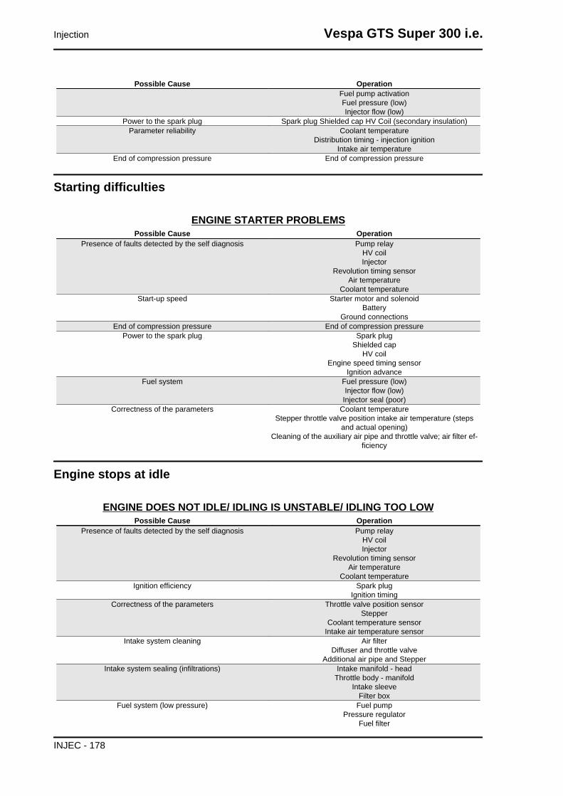
Possible Cause OperationFuel pump activationFuel pressure (low)Injector flow (low)
Power to the spark plug Spark plug Shielded cap HV Coil (secondary insulation)Parameter reliability Coolant temperature
Distribution timing - injection ignitionIntake air temperature
End of compression pressure End of compression pressure
Starting difficulties
ENGINE STARTER PROBLEMSPossible Cause Operation
Presence of faults detected by the self diagnosis Pump relayHV coilInjector
Revolution timing sensorAir temperature
Coolant temperatureStart-up speed Starter motor and solenoid
BatteryGround connections
End of compression pressure End of compression pressurePower to the spark plug Spark plug
Shielded capHV coil
Engine speed timing sensorIgnition advance
Fuel system Fuel pressure (low)Injector flow (low)
Injector seal (poor)Correctness of the parameters Coolant temperature
Stepper throttle valve position intake air temperature (stepsand actual opening)
Cleaning of the auxiliary air pipe and throttle valve; air filter ef-ficiency
Engine stops at idle
ENGINE DOES NOT IDLE/ IDLING IS UNSTABLE/ IDLING TOO LOWPossible Cause Operation
Presence of faults detected by the self diagnosis Pump relayHV coilInjector
Revolution timing sensorAir temperature
Coolant temperatureIgnition efficiency Spark plug
Ignition timingCorrectness of the parameters Throttle valve position sensor
StepperCoolant temperature sensor
Intake air temperature sensorIntake system cleaning Air filter
Diffuser and throttle valveAdditional air pipe and Stepper
Intake system sealing (infiltrations) Intake manifold - headThrottle body - manifold
Intake sleeveFilter box
Fuel system (low pressure) Fuel pumpPressure regulator
Fuel filter
Injection Vespa GTS Super 300 i.e.
INJEC - 178
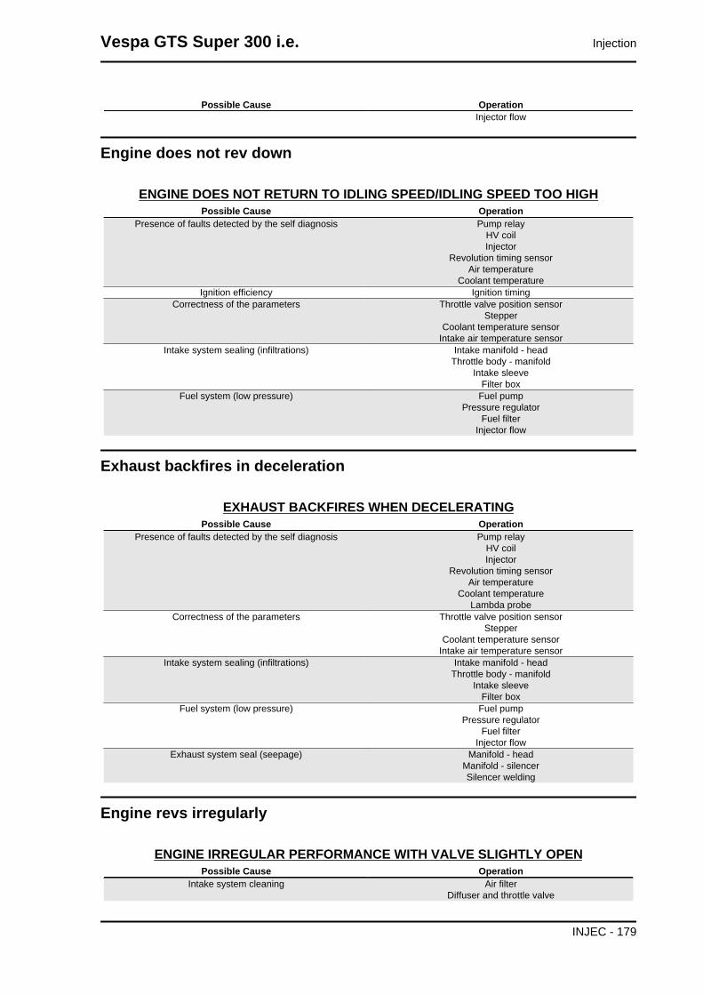
Possible Cause OperationInjector flow
Engine does not rev down
ENGINE DOES NOT RETURN TO IDLING SPEED/IDLING SPEED TOO HIGHPossible Cause Operation
Presence of faults detected by the self diagnosis Pump relayHV coilInjector
Revolution timing sensorAir temperature
Coolant temperatureIgnition efficiency Ignition timing
Correctness of the parameters Throttle valve position sensorStepper
Coolant temperature sensorIntake air temperature sensor
Intake system sealing (infiltrations) Intake manifold - headThrottle body - manifold
Intake sleeveFilter box
Fuel system (low pressure) Fuel pumpPressure regulator
Fuel filterInjector flow
Exhaust backfires in deceleration
EXHAUST BACKFIRES WHEN DECELERATINGPossible Cause Operation
Presence of faults detected by the self diagnosis Pump relayHV coilInjector
Revolution timing sensorAir temperature
Coolant temperatureLambda probe
Correctness of the parameters Throttle valve position sensorStepper
Coolant temperature sensorIntake air temperature sensor
Intake system sealing (infiltrations) Intake manifold - headThrottle body - manifold
Intake sleeveFilter box
Fuel system (low pressure) Fuel pumpPressure regulator
Fuel filterInjector flow
Exhaust system seal (seepage) Manifold - headManifold - silencerSilencer welding
Engine revs irregularly
ENGINE IRREGULAR PERFORMANCE WITH VALVE SLIGHTLY OPENPossible Cause Operation
Intake system cleaning Air filterDiffuser and throttle valve
Vespa GTS Super 300 i.e. Injection
INJEC - 179

Possible Cause OperationAdditional air pipe and Stepper
Intake system sealing Intake sleeveFilter box
Ignition system Spark plug wear checkParameter reliability Throttle valve position signal
Coolant temperature indicatorIntake air temperature indicator
Ignition advanceTPS reset successful TPS reset successful
Presence of faults detected by the self diagnosis Pump relayHV coilInjector
Revolution timing sensorAir temperature
Coolant temperatureLambda probe
Poor performance at full throttle
POOR ENGINE PERFORMANCE AT FULL POWER/ ENGINE IRREGULAR PERFORM-ANCE ON PICKUP
Possible Cause OperationPresence of faults detected by the self diagnosis Pump relay
HV coilInjector
Revolution timing sensorAir temperature
Coolant temperatureLambda probe
Power to spark plug Spark plugShielded cap
HV CableHV Coil
Intake system Air filterFilter box (sealing)
Intake sleeve (sealing)Parameter reliability Throttle valve position signal
Coolant temperature indicatorIntake air temperature indicator
Ignition advanceFuel system Fuel level in the tank
Fuel pressureFuel filter
Injector flow
Engine knocking
PRESENCE OF KNOCKING (COMBUSTION SHOCKS)Possible Cause Operation
Presence of faults detected by the self diagnosis Pump relayHV coilInjector
Revolution timing sensorAir temperature
Coolant temperatureLambda probe
Ignition efficiency Spark plugParameter reliability Throttle valve position signal
Coolant temperature indicatorIntake air temperature indicator
Ignition advanceIntake system sealing Intake sleeve
Injection Vespa GTS Super 300 i.e.
INJEC - 180

Possible Cause OperationFilter box
TPS reset successful TPS reset successfulFuel system Fuel pressure
Fuel filterInjector flowFuel quality
Selecting the thickness for the cylinder base gasket Selecting the thickness for the cylinder base gasket
Fuel supply system
The fuel supply circuit includes the electric pump, the filter, the pressure regulator, the electro-injector
and the fuel delivery pipes.
The electrical pump is located in the tank from which the fuel is pumped and sent to the injector through
the filter.
The pressure is controlled by the pressure regulator situated in the pump assembly in the tank.
Vespa GTS Super 300 i.e. Injection
INJEC - 181

Removing the butterfly valve
Remove the fuel piping clamping screw indicated
in the figure.
Remove the fast-release fittings from the injector
support.
Remove the injector connector.
Remove the three screws fixing the manifold to the
cylinder head and the clip fixing the throttle body
to the manifold.
Injection Vespa GTS Super 300 i.e.
INJEC - 182
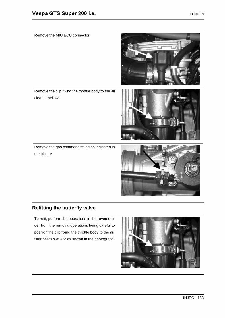
Remove the MIU ECU connector.
Remove the clip fixing the throttle body to the air
cleaner bellows.
Remove the gas command fitting as indicated in
the picture
Refitting the butterfly valve
To refit, perform the operations in the reverse or-
der from the removal operations being careful to
position the clip fixing the throttle body to the air
filter bellows at 45° as shown in the photograph.
Vespa GTS Super 300 i.e. Injection
INJEC - 183

Pump supply circuit
1. Battery 12V
2. Fuse No. 2 of 15A
3. 30A fuse No. 1
4. Key switch contacts
5. Fuse No. 5 of 7.5A
6. Injection load remote control
7. Fuel pump
8. H.V. coil.
Injection Vespa GTS Super 300 i.e.
INJEC - 184

9. Fuel injector
10.Electric fan solenoid
When switched to "ON", the fuel pump starts to rotate for two seconds and then stops. When the engine
starts, in the presence of rpm timing signal the pump is continuously supplied.
ELECTRICAL DATA
• Pump winding resistance ~ 1.5 Ohm
• Input current during regular operation 1.4 ÷ 1.8 A
• Input current to the closed hydraulic circuit ~ 2 A (to be checked with appropriate tool for
fuel pressure control choking the circuit on the return pipe)
Check that the injection load 15A fuse No. 2 works
properly.
Check that the 7.5A fuse No. 5 for live control unit
power works properly.
Check the efficiency of the injection load solenoid.
Check the resistance of the energising coil be-
tween pins 86 and 85: 40 to 80 Ohm
Apply a voltage of 12V to pins 86 and 85; make
sure that there is continuity between pins 30 and
87 of the remote control.
Check the power supply line of the injection load
solenoid energising coil: after switching to "ON",
make sure there is battery voltage, for two sec-
onds, between the Red-White cable and Black-
Purple cable of the solenoid control base. If there
is not, check the continuity of the Red-White cable
between the fuse box under the saddle hinge and
the remote control base and of the Black-Purple
cable between pin 22 of the control unit and the
remote control base.N.B.
Vespa GTS Super 300 i.e. Injection
INJEC - 185

CONTINUITY TESTS MUST BE CARRIED OUT WITH THECOMPONENTS DISCONNECTED. (REMOTE CONTROLS,ELECTRONIC CONTROL UNIT, FUSES, ETC.).
Check the presence of fixed voltage between the
grey/black cable of the remote control base and
earth. If there is none check the continuity of the
grey/black cable between the fuse box (No. 2 15
A) and the remote control base.N.B.CONTINUITY TESTS MUST BE CARRIED OUT WITH THECOMPONENTS DISCONNECTED. (REMOTE CONTROLS,ELECTRONIC CONTROL UNIT, FUSES, ETC.).
Injection Vespa GTS Super 300 i.e.
INJEC - 186

pump circuit 6
Check, on switching to "ON", that there is battery
voltage, for about two seconds, to the Black-Green
cable of the pump connector and ground with
pump connector disconnected. Otherwise, check
the continuity of the Black-Green cable between
the pump connector and the remote control base.
Check the efficiency of the ground line of the fuel
pump by measuring the continuity between the
pump connector black cable, system side, and the
ground.
If, when switching to "ON", the pump continues to
turn after two seconds of activation, check, with the
control unit disconnected and the injection load re-
mote control disconnected, that the Black-Purple
cable (pin 20 on the interface wiring) is insulated
from the ground.
Specific tooling020331Y Digital multimeter
Circuit leak test
Install the specific tool for checking the fuel pressure, with the pipe fitted with the gauge.
Vespa GTS Super 300 i.e. Injection
INJEC - 187
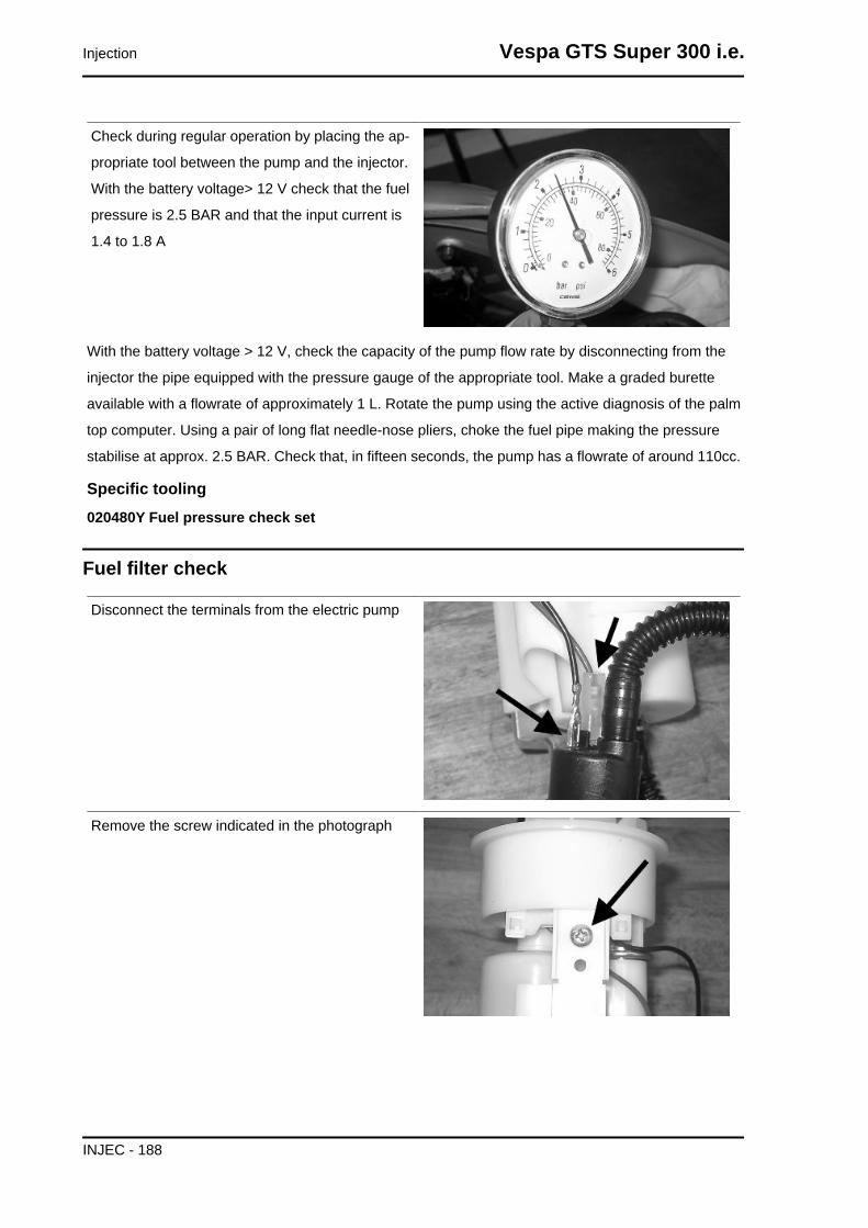
Check during regular operation by placing the ap-
propriate tool between the pump and the injector.
With the battery voltage> 12 V check that the fuel
pressure is 2.5 BAR and that the input current is
1.4 to 1.8 A
With the battery voltage > 12 V, check the capacity of the pump flow rate by disconnecting from the
injector the pipe equipped with the pressure gauge of the appropriate tool. Make a graded burette
available with a flowrate of approximately 1 L. Rotate the pump using the active diagnosis of the palm
top computer. Using a pair of long flat needle-nose pliers, choke the fuel pipe making the pressure
stabilise at approx. 2.5 BAR. Check that, in fifteen seconds, the pump has a flowrate of around 110cc.
Specific tooling020480Y Fuel pressure check set
Fuel filter check
Disconnect the terminals from the electric pump
Remove the screw indicated in the photograph
Injection Vespa GTS Super 300 i.e.
INJEC - 188

Remove the clamp fixing the piping to the filter
shown in the photograph
Separate the lower part of the pump support as
shown in the photograph.
Remove the filter from the pump support
Vespa GTS Super 300 i.e. Injection
INJEC - 189

Inspecting the injector circuit
1. Battery 12V
2. Fuse No. 2 of 15A
3. 30A fuse No. 1
4. Key switch contacts
Injection Vespa GTS Super 300 i.e.
INJEC - 190

5. Fuse No. 5 of 7.5A
6. Injection load relay
7. Fuel pump
8. H.V. coil.
9. Fuel injector
10.Electric fan solenoid
11.Coolant electric pump
Checking the resistance at the injector ends: 14.5 ± 5% Ohm
Check that the injection load 15A fuse No. 2 works
properly.
Check that the 7.5A fuse No. 5 for live control unit
power works properly.
Check the efficiency of the injection load solenoid.
Check the resistance of the energising coil be-
tween pins 86 and 85: 40 to 80 Ohm
Apply a voltage of 12V to pins 86 and 85; make
sure that there is continuity between pins 30 and
87 of the remote control.
Check the power supply line of the injection load
solenoid energising coil: after switching to "ON",
make sure there is battery voltage, for two sec-
onds, between the Red-White cable and Black-
Purple cable of the solenoid control base. If there
is not, check the continuity of the Red-White cable
between the fuse box under the saddle hinge and
the remote control base and of the Black-Purple
cable between pin 22 of the control unit and the
remote control base.N.B.CONTINUITY TESTS MUST BE CARRIED OUT WITH THECOMPONENTS DISCONNECTED. (REMOTE CONTROLS,ELECTRONIC CONTROL UNIT, FUSES, ETC.).
Vespa GTS Super 300 i.e. Injection
INJEC - 191

Check the presence of fixed voltage between the
grey/black cable of the remote control base and
earth. If there is none check the continuity of the
grey/black cable between the fuse box (No. 2 15
A) and the remote control base.N.B.CONTINUITY TESTS MUST BE CARRIED OUT WITH THECOMPONENTS DISCONNECTED. (REMOTE CONTROLS,ELECTRONIC CONTROL UNIT, FUSES, ETC.).
Injection Vespa GTS Super 300 i.e.
INJEC - 192

With the control unit and the injector disconnected,
check the continuity of the Red-Yellow cable be-
tween pin 34 of the interface wiring and the injector
connector
Switch to «ON» and check if there is voltage, with
injector disconnected and control unit connected,
between the Black-Green cable of the injector con-
nector and the ground lead
Vespa GTS Super 300 i.e. Injection
INJEC - 193

With injector disconnected and the injector load
solenoid disconnected, check the continuity of the
Black-Green cable between the injector connector
and solenoid base.
Inspecting the injector hydraulics
To carry out the injector check, remove the intake
manifold by removing the three clamping screws
at the head and the clip connecting the control unit
to the manifold.
Install the specific tool to check the fuel pressure
and position the manifold on a graduated container
of at least 100 cm³. Connect the injector with the
cable that is part of the equipment for the injection
tester. Connect the clamps of the cable to an aux-
iliary battery. Activate the fuel pump with the active
diagnosis. Check that, within fifteen seconds, ap-
proximately 40 cm³ of fuel is dispensed with an
adjustment pressure of approximately 2.5 BAR.
Specific tooling020480Y Fuel pressure check set
Injection Vespa GTS Super 300 i.e.
INJEC - 194

Proceed with the injector seal test.
Dry the injector outlet with a blast of compressed
air. Activate the fuel pump. Wait for one minute,
making sure there are no leaks coming from the
injector. Slight oozing is normal.
Value limit = 1 drop per minute
Vespa GTS Super 300 i.e. Injection
INJEC - 195

HT coil
1. Battery 12V
2. Fuse No. 2 of 15A
3. 30A fuse No. 1
4. Key switch contacts
5. Fuse No. 5 of 7.5A
6. Injection load remote control
7. Fuel pump
8. H.V. coil.
Injection Vespa GTS Super 300 i.e.
INJEC - 196

9. Fuel injector
10.Electric fan solenoid
The combined ignition/injection system is a high-efficiency induction system.
The control unit manages two significant parameters:
- Ignition advance
This is optimised at once according to the engine revs, engine load, temperature and ambient pressure.
With idle engine, it is optimised to obtain the stabilisation of the speed at 1450 ± 50 R/1'.
- Magnetisation time
The coil magnetisation time is controlled by the control unit. The power of the ignition is increased during
the engine start-up phase.
The injection system recognises the 4-stroke cycle so ignition is only commanded in the compression
phase.
Specific tooling020331Y Digital multimeter
Check that the injection load 15A fuse No. 2 works
properly.
Check that the 7.5A fuse No. 5 for live control unit
power works properly.
Check the efficiency of the injection load solenoid.
Check the resistance of the energising coil be-
tween pins 86 and 85: 40 to 80 Ohm
Apply a voltage of 12V to pins 86 and 85; make
sure that there is continuity between pins 30 and
87 of the remote control.
Vespa GTS Super 300 i.e. Injection
INJEC - 197

Check the power supply line of the injection load
solenoid energising coil: after switching to "ON",
make sure there is battery voltage, for two sec-
onds, between the Red-White cable and Black-
Purple cable of the solenoid control base. If there
is not, check the continuity of the Red-White cable
between the fuse box under the saddle hinge and
the remote control base and of the Black-Purple
cable between pin 22 of the control unit and the
remote control base.N.B.CONTINUITY TESTS MUST BE CARRIED OUT WITH THECOMPONENTS DISCONNECTED. (REMOTE CONTROLS,ELECTRONIC CONTROL UNIT, FUSES, ETC.).
Injection Vespa GTS Super 300 i.e.
INJEC - 198

Check the presence of fixed voltage between the
grey/black cable of the remote control base and
earth. If there is none check the continuity of the
grey/black cable between the fuse box (No. 2 15
A) and the remote control base.N.B.CONTINUITY TESTS MUST BE CARRIED OUT WITH THECOMPONENTS DISCONNECTED. (REMOTE CONTROLS,ELECTRONIC CONTROL UNIT, FUSES, ETC.).
Zeroing the throttleThrottle valve position signal reset (TPS reset)
The MIU control unit is supplied with a throttle valve position sensor that is pre-calibrated.
Pre-calibration entails regulating the minimum opening of the throttle valve to obtain a specific air flow
under pre-set reference conditions.
Pre-calibration ensures optimal air flow for the control of the idle speed.
This regulation must not be tampered with in any way whatsoever.
The injection system will complete the management of the idling through the Stepper and the variation
of the ignition advance.
After the pre-calibration the throttle body has an open valve with a variable angle depending on the
tolerances of the machining of the pipe and the valve itself.
The valve position sensor can also have various fitting positions. For these reasons the mVs of the
sensor with the valve at idle can vary from one throttle body to another.
Vespa GTS Super 300 i.e. Injection
INJEC - 199

To obtain the optimum carburetion, especially at small openings of the throttle valve, it is essential to
match the throttle body with the control unit following the procedure known as TPS resetting.
With this operation we inform the control unit, as a starting point, of the mV value corresponding to the
pre-calibrated position.
To reset, proceed as follows.
Connect the diagnostic tester.
Shift to «ON».
Select the functions of the diagnostic tester on «TPS RESET».
Specific tooling020922Y Diagnosis Tool
Make sure that the throttle valve control is in con-
tact with the stop screw.
Guaranteeing that this position will be kept, give the confirmation for the TPS reset procedure.
Reset should be performed in the following cases:
- on first fitting.
- if the injection control unit is replaced.N.B.
THE TPS RESETTING PROCEDURE MUST NOT BE CARRIED OUT WITH A USED THROTTLEBODY BECAUSE POSSIBLE VALVE WEAR AND STOP WEAR FOR THE MINIMUM OPENINGMAKE THE AIR FLOW DIFFERENT FROM THAT OF THE PRE-CALIBRATION.
Given that the TPS resetting is also done when the
control unit is replaced, place the control unit - filter
box bellows at 45° during the refitting operation as
shown in the picture.
Injection Vespa GTS Super 300 i.e.
INJEC - 200

Impianto elettroventilatore
1. Battery 12V
2. Fuse No. 2 of 15A
3. 30A fuse No. 1
4. Key switch contacts
5. Fuse No. 5 of 7.5A
6. Injection load relay
7. Fuel pump
Vespa GTS Super 300 i.e. Injection
INJEC - 201

8. H.V. coil.
9. Fuel injector
10.Electric fan solenoid
11.15A fuse No. 3
12.Electric fan motor
Check that the 7.5A fuse No. 5 works properly
With the key switch set to ON, check if there is +12
V battery voltage between the RED - WHITE cable
of the electric fan remote control and the ground
connection.
Check if the RED - WHITE cable between the fuse
box (under the saddle) and the electric fan remote
control base is not interrupted
Using a diagnosis Palmtop, carry out an active di-
agnosis for the "ELECTRIC FAN". Check if there
is battery voltage at pins 85 - 86 of the electric fan
relay
Check if the BLUE - YELLOW cable between the control unit pin 8 and the electric fan remote control
base is not interrupted
Injection Vespa GTS Super 300 i.e.
INJEC - 202

Check the 15A Fuse No. 3
Check if there is +12 V voltage between the GREY
cable of the electric fan remote control base and
the ground connection.
Check if the RED - BLACK cable between the fuse
box under the seat and the fuse box in the glove-
box compartment is not interrupted.
Check if the GREY cable between the fuse box in
the glove-box compartment and the electric fan
remote control base is not interrupted.
Check if the RED cable between the electric fan
remote control base and the electric fan motor is
not interrupted.
Check that the electric fan motor is earthed.
Vespa GTS Super 300 i.e. Injection
INJEC - 203

INDEX OF TOPICS
SUSPENSIONS SUSP

This section is dedicated to operations that can be carried out on the suspensions.
Front
Removing the front wheel
- Support the vehicle adequately.
- Loosen the five screws fixing the wheel to the
hub.
Front wheel hub overhaul
- Support the vehicle adequately.
- Remove the front wheel.
- Remove the front brake calliper.
- Remove the cotter pin and remove the cap.
- Unscrew the nut fixing the front wheel hub.
- Remove the wheel hub.
Vespa GTS Super 300 i.e. Suspensions
SUSP - 205

- Remove the ball bearing check Seeger ring indi-
cated in the picture
Extract the ball bearing using the specific tool
Specific tooling001467Y014 Calliper to extract 15-mm diame-ter bearings
001467Y017 Bell for bearings, OD 39 mm
- Remove the oil seal on the roller bearing side
using a screwdriver.
- Remove the roller bearing using the specific tool
Specific tooling020376Y Adapter handle
020456Y Ø24 mm adaptor
020363Y 20 mm guide
Suspensions Vespa GTS Super 300 i.e.
SUSP - 206

- Heat the roller bearing seat with a heat gun
- Use the specific tool to introduce and push the
bearing until it stops, with the shielded side facing
out
- Refit the ball bearing check Seeger ring
Specific tooling020151Y Air heater
020376Y Adapter handle
020357Y 32 x 35 mm adaptor
020412Y 15 mm guide
- Use the specific tool to fit and push the roller cas-
ing until it stops
- Refit the oil seal on the roller bearing side
- Lubricate the area between the roller bearing and
the ball bearing
Specific tooling020038Y Punch
Recommended productsAGIP GREASE MU3 Yellow-brown, lithium-base, medium-fibre multipurpose grease.ISO L-X-BCHA 3 - DIN 51 825 K3K -20
- To refit, follow the removal steps but in reverse order; be careful to tighten to the prescribed torque.
Locking torques (N*m)Front wheel axle nut 75 to 90
Refitting the front wheel
- Upon refitting, tighten the five screws to the pre-
scribed torque.
Locking torques (N*m)Wheel rim screws 20 - 25
Steering column
Vespa GTS Super 300 i.e. Suspensions
SUSP - 207

Removal
After removing the upper seat, lean the vehicle on
one side and extract the steering tube completely
from the fork.
Specific tooling020055Y Wrench for steering tube ring nut
Overhaul
Servicing the front suspension-steering assembly, described below, deals mainly with replacing parts
(pin- NADELLA roller bushings - sealing rings unit and dust gaiter) which connect the steering tube to
the front wheel holder swinging hub.N.B.
BEFORE PROCEEDING WITH THE DESCRIBED SERVICE, CHECK THAT THE STEERING TUBEAND THE WHEEL HOLDER HUB ARE IN EXCELLENT CONDITIONS: ONLY THEN IS THE SERV-ICE JUSTIFIABLE.MOREOVER, REMEMBER THE STEERING TUBE SHOULD BE REPLACED WITH A NEW ONEWHEN DEFORMED.
a = Ø 12 Punch
b = Sharp-edged end
Use a suitable punch with the dimensions indica-
ted on the figure; hit with a mallet until the wedging
washer is crushed and then extract it with the help
of a pointed end.
Repeat the operation for the second washer using
the punch on the side opposite to the one shown
in the figure.
Use the tool fitted with part 1 as shown in the figure
and move the tool handgrip until the pin and the
NADELLA are simultaneously ejected in the direc-
tion opposite the tool thrusting force.
After removing the pin and the first NADELLA, the
swinging hub gets detached from the steering
tube.
Suspensions Vespa GTS Super 300 i.e.
SUSP - 208

To remove the second NADELLA, use the tool fit-
ted with part 2 instead of part 1, on the side oppo-
site the one shown in the figure.N.B.DURING THE REMOVAL OPERATIONS DESCRIBEDABOVE, THE ROLLER BUSHINGS ARE DESTROYEDWHEN THE EXTRACTOR IS USED. UPON REFITTING, IT ISTHEREFORE NECESSARY TO USE NEW BUSHINGS ASWELL AS A NEW PIN, NEW SEALING RINGS AND DUSTGAITER.
Specific tooling020021Y Front suspension service tool
Connect the swinging hub to the steering tube with
the guiding pin.
- Use the tool fitted with part 3 on the stem and part
4.
Lubricate the pin with recommended grease and
insert it temporarily on the swinging hub, move the
tool handgrip until part 3 is fully inserted on the
steering tube.
After fitting the pin, insert the two spacers, slightly
hitting them with the mallet.N.B.BEFORE PROCEEDING WITH THE DESCRIBED FITTING,PLACE THE TWO DUST GAITER RINGS ON THE SWING-ING HUB AS SHOWN IN THE FIGURE.
Specific tooling020021Y Front suspension service tool
Recommended productsAGIP GREASE SM 2 Gray black smooth-tex-tured lithium grease, containing molybdenumdisulphide.-
Insert the sealing ring on the pin and the roller
bushing with its wedging washer at the same time.
- Remove the tool and the part 5 (guide), which has
been partially ejected during the previous pin fitting
phase, and leave part 4 always fitted.
- Replace part 3 with part 16 (on the stem).
- By moving the tool handgrip, push the wedging
washer - roller bushing - seal ring unit, placing part
16 until it stops on the swinging hub.
Vespa GTS Super 300 i.e. Suspensions
SUSP - 209

- Repeat the above operation using the tool with
part 16 and part 22, instead of part 4, always fitted
to the stem, on the side opposite that indicated in
the figure to fit the second wedging washer - roller
bushing - sealing ring unit.WARNINGBEFORE PROCEEDING WITH THE DESCRIBED PRE-FIT-TING, DIP THE SEALING RINGS IN MINERAL OIL AND THE"NADELLA" ROLLER BUSHINGS (PREVIOUSLY WASHEDIN PURE PETROL OR NEUTRAL PETROLEUM TO ELIMI-NATE THE ANTIRUST PROTECTION), HALF-FILLED WITHGREASE.
Specific tooling020021Y Front suspension service tool
Recommended productsAGIP GREASE MU3 Yellow-brown, lithium-base, medium-fibre multipurpose grease.ISO L-X-BCHA 3 - DIN 51 825 K3K -20
- Use the tool fitted with part 20 on its stem and
part 21 on the tool base as shown in the figure.
- By moving the tool handgrip, push the two NA-
DELLA bushings until their internal bottoms make
contact with the pin end.
- Use the tool fitted with parts 3 and 4 to fit the pin,
and press moving the tool handgrip, until wedging
the washers on the swinging hub.
- Now, remove the two spacers (parts 17 and 16)
and, once the space between the NADELLAs -
steering tube and swinging hub - has been fully
filled with grease, move the dust gaiter rings until
they are placed in that space.
- By wedging the washers as described above, the
front suspension unit refitting stage is finished.
Recommended productsAGIP GREASE MU3 Yellow-brown, lithium-base, medium-fibre multipurpose grease.ISO L-X-BCHA 3 - DIN 51 825 K3K -20
RefittingCAUTION
USE NEW ROLLER CASINGS, PIN, SEALING RINGS AND DUST GUARDS FOR REFITTING.
Suspensions Vespa GTS Super 300 i.e.
SUSP - 210

When fitting the fork, lubricate with the steering
bearing tracks with the recommended grease.
Tighten the lower ring nut "A" and the upper ring
nut "B" to the specified torque
Recommended productsAGIP GREASE PV2 Ivory smooth-textured,slightly-stringy anhydrous calcium-basegrease.TL 9150 066, symbol NATO G 460
Locking torques (N*m)Lower steering ring nut 8 ÷ 10 Upper steeringring nut 35 to 40
Front shock absorber
Vespa GTS Super 300 i.e. Suspensions
SUSP - 211

Removal
- Unscrew the fixing screw of the shock absorber
cover and remove the plastic by unscrewing it
downwards.
- Remove the swinging hub cover by disengaging
the fittings.
- Support the vehicle adequately.
- Remove the wheel hub.
- Remove the seeger indicated in the photograph.
- Unscrew and remove the shock absorber lower
retainer.
- Remove the brake calliper shock absorber sup-
port.
- Remove the two upper fixing screws.
- Remove the front shock absorber.
Refitting
To refit, carry out the removal operations in reverse order, observing the prescribed tightening torques.
Suspensions Vespa GTS Super 300 i.e.
SUSP - 212
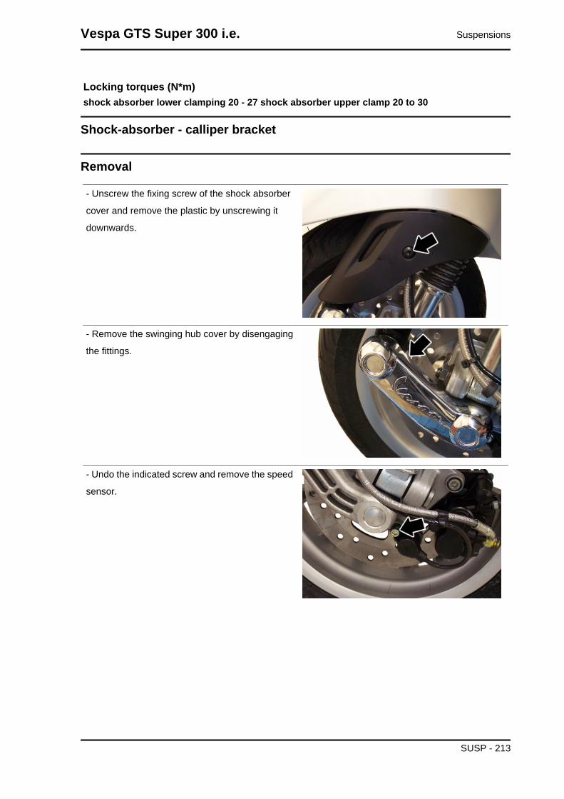
Locking torques (N*m)shock absorber lower clamping 20 - 27 shock absorber upper clamp 20 to 30
Shock-absorber - calliper bracket
Removal
- Unscrew the fixing screw of the shock absorber
cover and remove the plastic by unscrewing it
downwards.
- Remove the swinging hub cover by disengaging
the fittings.
- Undo the indicated screw and remove the speed
sensor.
Vespa GTS Super 300 i.e. Suspensions
SUSP - 213
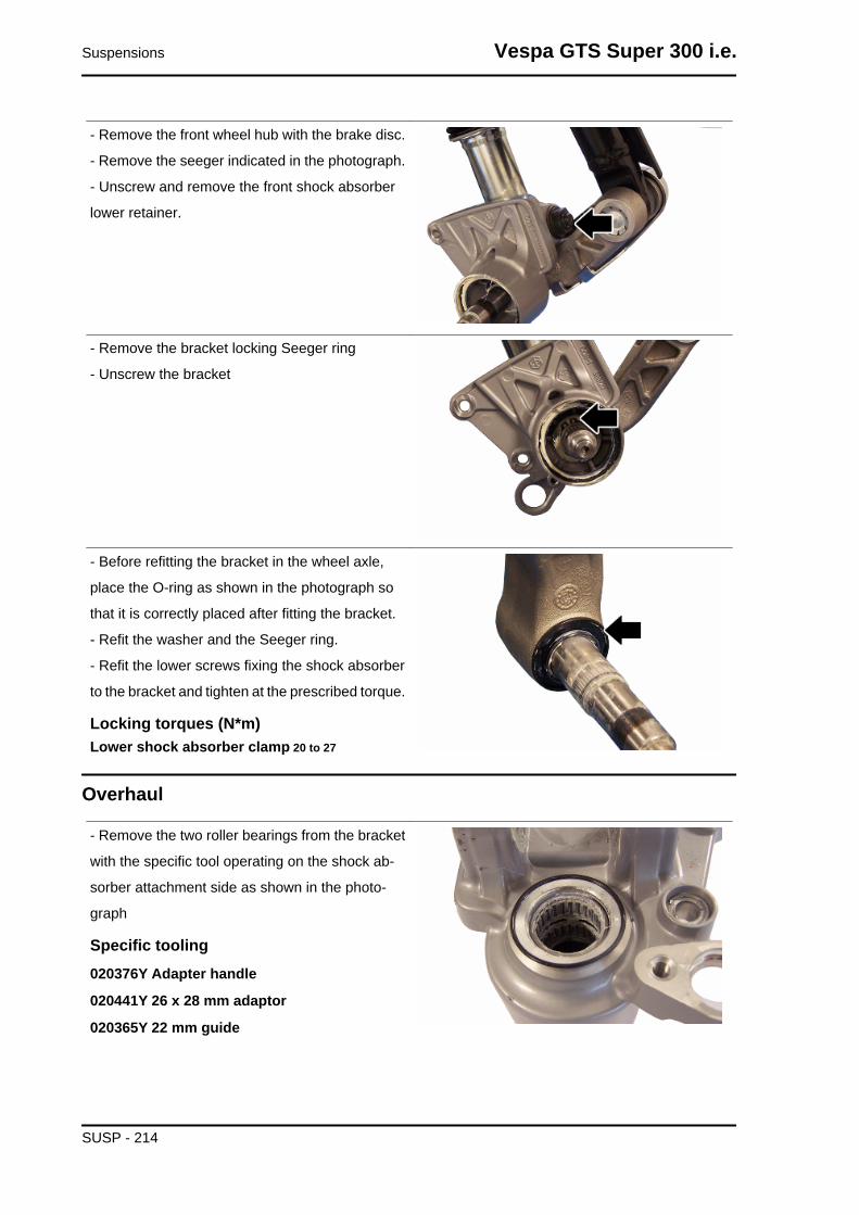
- Remove the front wheel hub with the brake disc.
- Remove the seeger indicated in the photograph.
- Unscrew and remove the front shock absorber
lower retainer.
- Remove the bracket locking Seeger ring
- Unscrew the bracket
- Before refitting the bracket in the wheel axle,
place the O-ring as shown in the photograph so
that it is correctly placed after fitting the bracket.
- Refit the washer and the Seeger ring.
- Refit the lower screws fixing the shock absorber
to the bracket and tighten at the prescribed torque.
Locking torques (N*m)Lower shock absorber clamp 20 to 27
Overhaul
- Remove the two roller bearings from the bracket
with the specific tool operating on the shock ab-
sorber attachment side as shown in the photo-
graph
Specific tooling020376Y Adapter handle
020441Y 26 x 28 mm adaptor
020365Y 22 mm guide
Suspensions Vespa GTS Super 300 i.e.
SUSP - 214

- Remove the oil seal on the wheel hub side with
the screwdriver as shown in the photograph
- Suitably hold the brake calliper - shock absorber attachment bracket
- Fit a new oil seal and move it until it stops using the specific tool
Specific tooling020376Y Adapter handle
020360Y 52 x 55-mm adaptor
- Assemble a new roller bearing on the shock absorber side and move it until it stops using the specific
tool
Specific tooling020036Y Punch
- Suitably hold the brake calliper - shock absorber attachment bracket
- Assemble a new roller bearing on the wheel hub side and move it until it stops using the specific tool
Specific tooling020037Y Punch
Refitting
- Refit the parts in reverse order of the removal
operation.CAUTIONBEFORE CARRYING OUT REFITTING OPERATIONS INTHE AREAS MARKED WITH AN ASTERISK, LUBRICATETHEM WITH THE RECOMMENDED PRODUCT
Specific tooling020036Y Punch
020037Y Punch
Recommended productsAGIP GREASE PV2 Ivory smooth-textured,slightly-stringy anhydrous calcium-basegrease.TL 9150 066, symbol NATO G 460
Vespa GTS Super 300 i.e. Suspensions
SUSP - 215
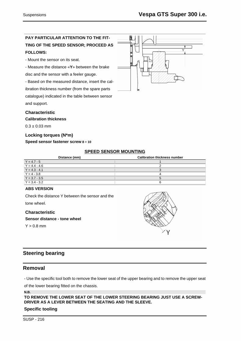
PAY PARTICULAR ATTENTION TO THE FIT-
TING OF THE SPEED SENSOR; PROCEED AS
FOLLOWS:
- Mount the sensor on its seat.
- Measure the distance «Y» between the brake
disc and the sensor with a feeler gauge.
- Based on the measured distance, insert the cal-
ibration thickness number (from the spare parts
catalogue) indicated in the table between sensor
and support.
CharacteristicCalibration thickness0.3 ± 0.03 mm
Locking torques (N*m)Speed sensor fastener screw 8 ÷ 10
SPEED SENSOR MOUNTINGDistance (mm) Calibration thickness number
Y = 4.7 - 5 1Y = 4.4 - 4.6 2Y = 4.3 - 4.1 3Y = 4 - 3.8 4Y = 3.7 - 3.5 5Y = 3.4 - 3.2 6
ABS VERSION
Check the distance Y between the sensor and the
tone wheel.
CharacteristicSensor distance - tone wheelY > 0.8 mm
Steering bearing
Removal
- Use the specific tool both to remove the lower seat of the upper bearing and to remove the upper seat
of the lower bearing fitted on the chassis.N.B.TO REMOVE THE LOWER SEAT OF THE LOWER STEERING BEARING JUST USE A SCREW-DRIVER AS A LEVER BETWEEN THE SEATING AND THE SLEEVE.Specific tooling
Suspensions Vespa GTS Super 300 i.e.
SUSP - 216

020004Y Punch to remove steering bearings from headstock
- Remove the fifth wheel fitting and the dust gaiter
on the steering bearing as shown in figure, using
the specific tool. Proceed giving a few taps with the
mallet.
Specific tooling020004Y Punch to remove steering bearingsfrom headstock
- Refit the fifth wheel fitting and the dust gaiter on
the steering bearing until they stop, using the spe-
cific tool.
Specific tooling006029Y Punch for fitting steering bearing seaton steering tube
Rear
Removing the rear wheel
- Remove the bracket supporting the rear shock
absorber and the muffler;
- Remove the rear wheel by unscrewing the 5
screws indicated in the photograph
Refitting the rear wheel
To refit, carry out the removal operations but in reverse order, observing the prescribed torques.
Locking torques (N*m)Wheel fixing screws: 20 - 25
Vespa GTS Super 300 i.e. Suspensions
SUSP - 217

ABS VERSION
Check the distance Y between the sensor and the
tone wheel.
If it results lower than indicated insert a 669282
washer between the sensor and the sensor sup-
port bracket.
CharacteristicSensor distance - tone wheelY > 0.4 mm
Swing-arm
Removal
- Place the vehicle on its centre stand;
- Remove the engine housing
- Remove the swinging arm/engine fitting shown in
the picture
- Move the engine back
- Remove the spring anchoring the swinging arm
to the chassis as shown in the picture
Suspensions Vespa GTS Super 300 i.e.
SUSP - 218

- Remove the two screws fixing the buffer support
bracket to the chassis
- Remove the left and right caps located under the
footrest to reach the pin fixing the swinging arm to
the body.
- Remove the pin. Then remove the swinging arm.
Vespa GTS Super 300 i.e. Suspensions
SUSP - 219
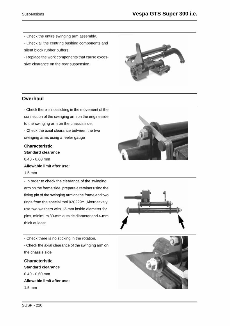
- Check the entire swinging arm assembly.
- Check all the centring bushing components and
silent block rubber buffers.
- Replace the work components that cause exces-
sive clearance on the rear suspension.
Overhaul
- Check there is no sticking in the movement of the
connection of the swinging arm on the engine side
to the swinging arm on the chassis side.
- Check the axial clearance between the two
swinging arms using a feeler gauge
CharacteristicStandard clearance0.40 - 0.60 mm
Allowable limit after use:1.5 mm
- In order to check the clearance of the swinging
arm on the frame side, prepare a retainer using the
fixing pin of the swinging arm on the frame and two
rings from the special tool 020229Y. Alternatively,
use two washers with 12-mm inside diameter for
pins, minimum 30-mm outside diameter and 4-mm
thick at least.
- Check there is no sticking in the rotation.
- Check the axial clearance of the swinging arm on
the chassis side
CharacteristicStandard clearance0.40 - 0.60 mm
Allowable limit after use:1.5 mm
Suspensions Vespa GTS Super 300 i.e.
SUSP - 220

- Separate the swinging arm on the engine side
from the vehicle side arm.
- Remove the plastic bushings and the internal
spacer shown in the picture.
- Using a suitable pin remove the roller casings as
shown in the pictures
- Using an appropriate tool plant new roller cas-
ings, being careful to position the bearings with the
seal rings facing outwards
Specific tooling020244Y 15-mm diameter punch
020115Y Ø 18 punch
CharacteristicLength of the swinging arm tube on the engineside:L 175.3 + 0.3 0
Length of the internal swinging arm spacer onthe engine side:L 183 + 0.3 0
Engine side swinging arm plastic bushingshim:3.5 ± 0.05 mm
Chassis side swinging arm plastic bushingshim:3.5 ± 0.05 mm
Length of the internal swinging arm spacer onthe frame side:290 ± 0.1 mm
Vespa GTS Super 300 i.e. Suspensions
SUSP - 221

Length of the swinging arm tube on the chas-sis side:283 ± 0.1 mm
- Lubricate roller casings and the plastic bushings
with grease
- Insert the spacers
- Assemble the two arms with the relative bolt in
the position shown in the picture
- Adjust the bolt as shown in the picture
- Position the chassis side swinging arm with the
most protruding part pointing towards the silent
block side as shown in the picture
Recommended productsAGIP GREASE PV2 Ivory smooth-textured,slightly-stringy anhydrous calcium-basegrease.TL 9150 066, symbol NATO G 460
- Make sure the silent bloc is not broken. If it is,
replace the coupling.
- Remove the Seeger ring shown in the picture
- Remove the full silent bloc bracket
- Undo the silent bloc ring shown in the picture
Suspensions Vespa GTS Super 300 i.e.
SUSP - 222

- Hold the full silent bloc bracket in the clamp
- Using the appropriate tool, remove the silent bloc
from the bracket from the side corresponding to
the inside of the vehicle. This is to guarantee the
tool is centred properly on the support
- Install a new silent bloc, making sure it aligns
properly with the reference tooth.
- Fit the silent blocs, making sure the chamfered
part of the silent bloc matches the chamfered part
of the bracket
- Using the appropriate tool, fit the silent bloc as
shown in the picture
Refitting
- To refit, perform the removal operations in reverse.
- Grease the bearings and the rolling parts with the recommended grease.
Vespa GTS Super 300 i.e. Suspensions
SUSP - 223

-Complete the fitting by tightening the nuts on the relative bolts to the proper tightening torque.
Locking torques (N*m)Engine- and vehicle-side swinging arm junction bolt 40 to 45 Swinging arm pin - Engine 64 ÷72 Body shell - Swinging arm pin 76 ÷ 83 Screw fixing the silent-block support plate to thebody 42 ÷ 52
Shock absorbers
Removal
Proceed as follows:
- place the vehicle on its centre stand;
- remove the luggage rack
- lift the engine a little with a jack so as to free the
two shock absorbers;
- remove the muffler assembly;
- undo the shock absorber spring assembly clamp-
ing screw from the support fixed to the engine on
the one side and from that fixed to the silencer on
the other;
- unscrew the two upper nuts (one on each side)
fixing the shock absorber spring assembly to the
frame and remove the shock absorbers.
Refitting
To refit, carry out the above removal operations in reverse order, observing the prescribed torques.
Locking torques (N*m)
Suspensions Vespa GTS Super 300 i.e.
SUSP - 224
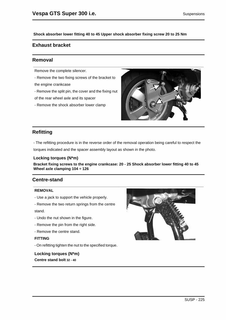
Shock absorber lower fitting 40 to 45 Upper shock absorber fixing screw 20 to 25 Nm
Exhaust bracket
Removal
Remove the complete silencer.
- Remove the two fixing screws of the bracket to
the engine crankcase
- Remove the split pin, the cover and the fixing nut
of the rear wheel axle and its spacer
- Remove the shock absorber lower clamp
Refitting
- The refitting procedure is in the reverse order of the removal operation being careful to respect the
torques indicated and the spacer assembly layout as shown in the photo.
Locking torques (N*m)Bracket fixing screws to the engine crankcase: 20 - 25 Shock absorber lower fitting 40 to 45Wheel axle clamping 104 ÷ 126
Centre-stand
REMOVAL
- Use a jack to support the vehicle properly.
- Remove the two return springs from the centre
stand.
- Undo the nut shown in the figure.
- Remove the pin from the right side.
- Remove the centre stand.
FITTING
- On refitting tighten the nut to the specified torque.
Locking torques (N*m)Centre stand bolt 32 - 40
Vespa GTS Super 300 i.e. Suspensions
SUSP - 225

Side stand
REMOVAL
- Uncouple the centre stand return spring;
Remove the screw shown in the photograph
FITTING
To refit, carry out the removal operations in re-
verse order and comply with the specified torque.
Locking torques (N*m)Side stand fixing bolt 35 - 40
Suspensions Vespa GTS Super 300 i.e.
SUSP - 226

INDEX OF TOPICS
BRAKING SYSTEM BRAK SYS
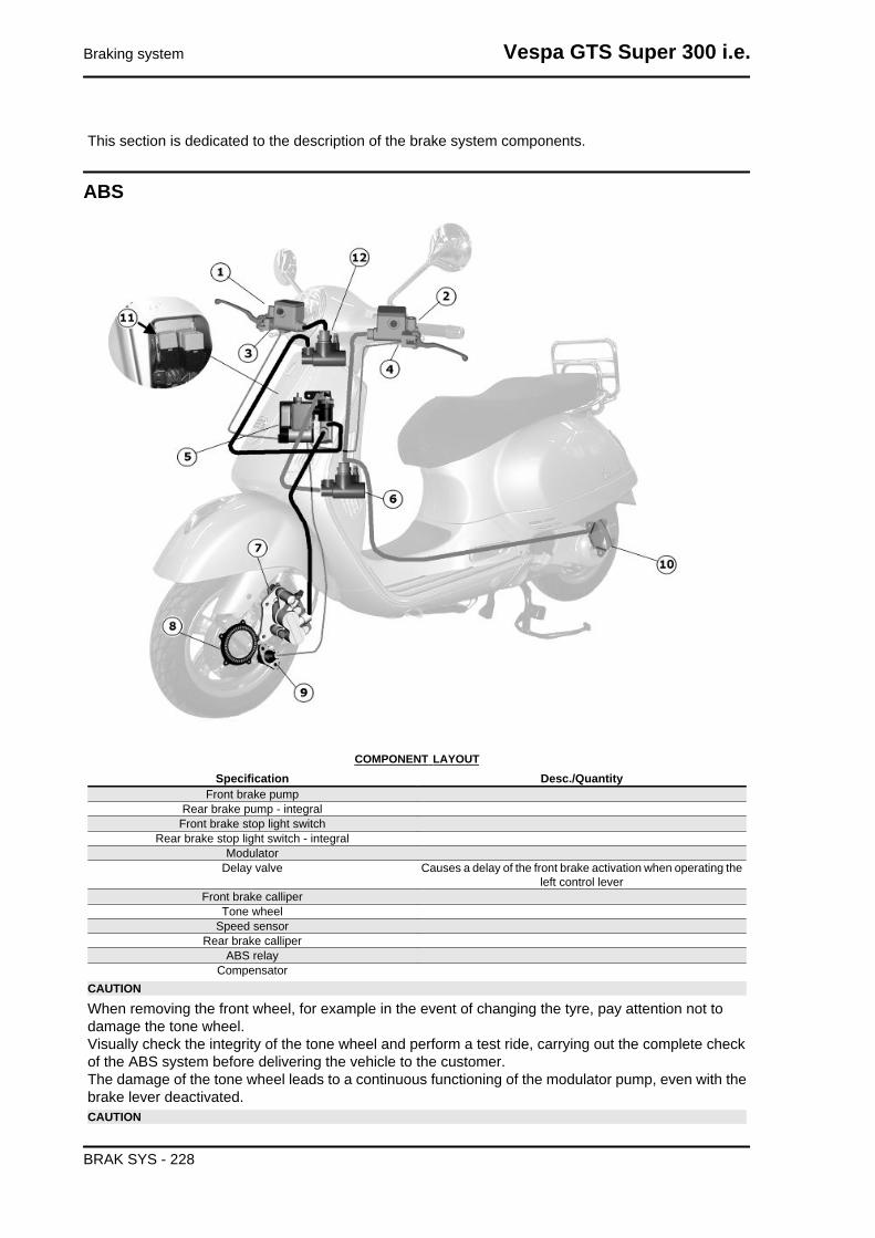
This section is dedicated to the description of the brake system components.
ABS
COMPONENT LAYOUTSpecification Desc./Quantity
Front brake pumpRear brake pump - integralFront brake stop light switch
Rear brake stop light switch - integralModulator
Delay valve Causes a delay of the front brake activation when operating theleft control lever
Front brake calliperTone wheel
Speed sensorRear brake calliper
ABS relayCompensator
CAUTION
When removing the front wheel, for example in the event of changing the tyre, pay attention not todamage the tone wheel.Visually check the integrity of the tone wheel and perform a test ride, carrying out the complete checkof the ABS system before delivering the vehicle to the customer.The damage of the tone wheel leads to a continuous functioning of the modulator pump, even with thebrake lever deactivated.CAUTION
Braking system Vespa GTS Super 300 i.e.
BRAK SYS - 228

AT EACH REMOVAL AND REFITTING OF THE FRONT WHEEL, CHECK THE DISTANCE BE-TWEEN SPEED SENSOR AND TONE WHEEL, WHICH MUST BE BETWEEN 0.5 mm AND 1.5 mm.IF NECESSARY ADJUST IT BY ADDING OR TAKING OFF CALIBRATED WASHERS OF 0.5 mmTHE ABS SYSTEM CHECK STARTS EVERY TIME TURNING THE KEY TO "ON" AND CAN BEREPEATED, ESPECIALLY AT HARSH CLIMATES, AFTER STARTING, AS IT IS DUE TO NORMALBATTERY VOLTAGE LOWERING CAUSED BY THE STARTER.
The vehicle is equipped with a locking ABS system
on the wheels.
A: Tone wheel
B: Speed sensor
• ABS: It is a hydraulic - electronic device
that limits the pressure within the brak-
ing circuit when a sensor, located on
the wheel, detects its tendency to lock.
This system prevents the wheels from
locking to avoid the risk of falling.
In case of failure of the ABS system, immediately
reported to the rider with ABS warning light on the
instrument panel, the vehicle retains the charac-
teristics of a conventional braking system. In case
of ABS warning light, reduce speed and go to an
Authorised Service Centre for the appropriate
checks.. The safety provided by the ABS does not,
in any case, justify risky manoeuvres. The stop-
ping distance may be greater, compared to a con-
ventional vehicle equipped with traditional braking
in the following conditions:
• Riding on rough roads, with gravel or
snow
• Riding on roads with holes or bumps
It is therefore recommended to reduce speed in
these conditions.
AT VERY LOW SPEEDS (LESS THAN 3 MPH) THE ABSSYSTEM IS DISABLED.IT IS RECOMMENDED TO PAY ATTENTION THEREFOREIN CASES OF BRAKING IN LOW GRIP CONDITIONS ATLOW SPEED (FOR EXAMPLE BRAKING ON GARAGEFLOOR TILES AFTER HAVING RIDDEN ON WET ROADSOR SIMILAR SITUATIONS)N.B.
Vespa GTS Super 300 i.e. Braking system
BRAK SYS - 229

THE ABS WARNING LIGHT TURNS ON AND STAYS ONUNTIL REACHING 3 MPH.CAUTION
IN THE EVENT OF MALFUNCTION OF THE BATTERY, THEABS - ASR SYSTEM TURNS OFF.
Modulator
To access the ABS system modulator remove the
leg shield back plate.
ASR
System ASR
ASR SYSTEM
The ASR system is a device to help riding that helps the rider during acceleration manoeuvres, espe-
cially on slippery surfaces or in conditions that can cause sudden slippage of the rear wheel. The ASR
in these situations automatically intervenes by reducing engine output within the limit imposed by the
grip conditions, contributing significantly to the maintenance of stability the vehicle.WARNING
THE ASR SYSTEM IS BASED ON THE RECOGNITION OF SPEED DIFFERENCES BETWEENFRONT AND REAR WHEEL. IN ORDER FOR THE SYSTEM TO MAINTAIN MAXIMUM EFFICIENCYIN ALL CONDITIONS, THE CALIBRATION PROCEDURE MUST BE PERFORMED EVERY TIME,EVEN IN CASE OF REPLACEMENT OF JUST ONE TYRE.FOR THE CALIBRATION OF THE CONTROL UNIT PERFORM THE PROCEDURE BELOW.
Braking system Vespa GTS Super 300 i.e.
BRAK SYS - 230

• BUTTON «1» (with the engine run-
ning): on / off.
• «2» EFI/ASR WARNING LIGHTindica-
tion light ASR and EFI operation (en-
gine malfunction).
N.B.THE WARNING LIGHT PERFORMS AN INITIAL CHECK WITH KEY ON; AFTERWARDS OPERATEAS DESCRIBED BELOW.N.B.THE ENGINE MALFUNCTION (EFI) HAS PRIORITY TO THE ASR FUNCTION.WARNINGUNDER NORMAL OPERATION (ASR INSERTED), THE ENGINE MALFUNCTION WARNING LIGHTIS OFF.Flashing mode:
- Frequency of 5 flashes per second (5 Hz), with vehicle running: the system is up and running (condi-
tions of low grip and intervention to reduce engine power); we recommend the utmost caution because
the grip limit has been exceeded; restore the vehicle safety conditions by gently reducing the throttle
opening.
- Frequency of 2 flashes per second (2 Hz), with vehicle running: the system is in calibration phase; for
the correct procedure refer to the following.
- Lit with moving vehicle: the system is disabled and will not intervene in case of loss of grip.
If the deactivation was voluntary (by pressing the appropriate button «1» for 1 second with the engine
running) it is recommended to reactivate the system as soon as possible.
To ensure maximum safety of the vehicle it is advisable to keep the system active. Deactivation may
be necessary only in case of starting with very low grip surfaces (mud, snow) on which the operation
of the ASR could actually prevent the movement of the vehicle.WARNING
Vespa GTS Super 300 i.e. Braking system
BRAK SYS - 231

THE ASR SYSTEM IS ACTIVATED AT EVERY «ON» POSITIONING OF THE IGNITION SWITCH.IF DISABLED BY THE USER, THE ASR SYSTEM KEEPS THE STATE OF INACTIVITY ONLY IFTHE VEHICLE IS OFF, BY USING THE ENGINE STOP SWITCH; AT THE NEXT KEY ON THE ASRSYSTEM IS ENABLED AUTOMATICALLY.CAUTION
IT IS EMPHASISED THAT THE RIDING AUXILIARY SYSTEM CAN NOT CHANGE THE PHYSICALLIMITS OF GRIP AND IS NOT A SUBSTITUTE FOR PROPER MANAGEMENT OF POWER, BOTHON STRAIGHT STRETCHES AND IN TURNS. THEREFORE, IT IS RECOMMENDED TO ALWAYSUSE THE VEHICLE WITH THE UTMOST CARE AND IN ACCORDANCE WITH THE REGULATIONSIN FORCE.CAUTION
AT LOW SPEED (LESS THAN 5 KM/H), THE ASR SYSTEM DOES NOT WORK.IT IS RECOMMENDED TO PAY PARTICULAR ATTENTION IN THE EVENT OF ACCELERATIONFROM STANDSTILL IN CONDITIONS OF LOW GRIP, ESPECIALLY IN THE FIRST METRES.N.B.
IN CASE OF ROADS FULL OF HOLES THERE MAY OCCUR BRIEF ACTIVATION OF THE ASRSYSTEM. THIS OCCURS UNDER NORMAL OPERATING CONDITIONS OF THE VEHICLE.N.B.
THE DEVICE PREVENTS IMPRESSING ON THE REAR HIGH SPEED ROTATION WHEEL WITHTHE VEHICLE ON THE CENTRE STAND. IT IS RECOMMENDED NOT TO INSIST WITH THETHROTTLE GRIP IN THIS PARTICULAR CONDITION.CAUTION
A POOR STATE OF MAINTENANCE OF THE TYRES CAN RESULT IN ABNORMAL OPERATIONOF THE ASR SYSTEM.IN CASE OF REPEATED INTERVENTIONS OF THE ASR, EVEN ON ROAD SURFACES WITHGOOD GRIP OR SMALL THROTTLE OPENINGS, IT IS NECESSARY TO CHECK FOR WEAR AND/OR THE STATE OF INFLATION OF TYRES FIRST. IF THE PROBLEM PERSISTS, CONTACT ANAUTHORISED SERVICE CENTRE.CAUTION
IN THE EVENT OF MALFUNCTION OF THE BATTERY, THE ABS - ASR SYSTEM TURNS OFF.
ASR SYSTEM CALIBRATION PROCEDURE.
In order to maintain the effectiveness of the ASR system following the replacement of one or both tyres
a calibration procedure of the system must be performed as follows on a straight flat stretch of road.
Please note that the request for activation of the procedure (steps 1 to 4) must be completed within 60
sec from ignition on the engine.
• It is necessary that the diagnostic phase of the ASR systems and ABS is complete: for this purpose,
after the key ON, ride a short distance above 5 km/h and wait for the flashing of the ABS warning light
and EFI/ASR to stop.
Braking system Vespa GTS Super 300 i.e.
BRAK SYS - 232

• Turn the ASR system off by pressing the button «1» on the handlebar and check that the ASR disabling
warning light «2» is on.
• Allow the engine to idle for at least 3 seconds.
• Press the ASR on/off button «1» and one of the two brake levers simultaneously for at least 4 seconds.
The activation of the procedure will be confirmed by turning on the EFI/ASR «2» warning light with a
frequency of 2 flashes per second (2 Hz).
• Accelerate to a constant speed of 30 to 40 km/h and maintain it for at least 7 to 8 seconds.
• The end of the procedure will be indicated by the flashing EFI/ASR warning light «2».
• Once the procedure is complete it is necessary to turn off the vehicle panel (key off) and wait 30
seconds before turning the panel on (key on).
• In case of failure to complete the procedure within 2 minutes the EFI/ASR warning light «2» will stay
on steady and the ASR will remain off until the panel is turned off (key off).
• To restart the ASR it is necessary to turn on vehicle panel (key on).
It is however necessary to repeat the process until it succeeds.
Rear brake calliper
Removal
- Remove the rear wheel.
- Remove the brake pad retention pin snap ring.
- Using a pin partially remove the brake pad re-
tention pin.
- Remove the screws fixing the brake calliper to
the crankcase then remove the brake calliper com-
plete with pipe.
- Complete the extraction of the pad retention pin,
the spring and the pads.N.B.IF IT IS NECESSARY TO REPLACE OR SERVICE THEBRAKE CALLIPER, BEFORE REMOVING THE FITTINGSFIXING THE CALLIPER TO THE SUPPORT BRACKET,FIRST LOOSEN THE OIL HOSE FITTING AFTER HAVINGEMPTIED THE SYSTEM OF THE CIRCUIT BEING EXAM-INED.
Refitting
- Follow the removal steps but in reverse order and tighten to the prescribed torque.
Vespa GTS Super 300 i.e. Braking system
BRAK SYS - 233

Locking torques (N*m)Calliper fixing screw 24 ÷ 27
If the calliper is replaced:CAUTION
ONCE REFITTING IS FINISHED, BLEED THE SYSTEM.CAUTION
ALWAYS USE NEW COPPER WASHERS.
Locking torques (N*m)Screw fixing the oil connection to the calliper 19 ÷ 24
Front brake calliper
Removal
- Remove the front wheel
- Pre-loosen the two fixing pins of the brake pads
- Remove the two front brake calliper devices fas-
tening them to the support as shown in the photo-
graph.N.B.WHEN A PROCEDURE IS PLANNED INCLUDING THESERVICE OR REPLACEMENT OF THE CALLIPER, FIRSTLOOSEN THE FITTING CONNECTING THE PIPE TO THEBRAKE CALLIPER
Braking system Vespa GTS Super 300 i.e.
BRAK SYS - 234
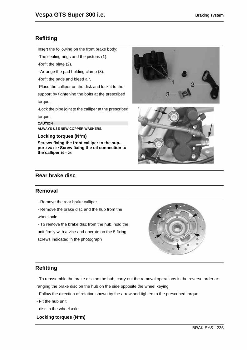
Refitting
Insert the following on the front brake body:
-The sealing rings and the pistons (1).
-Refit the plate (2).
- Arrange the pad holding clamp (3).
-Refit the pads and bleed air.
-Place the calliper on the disk and lock it to the
support by tightening the bolts at the prescribed
torque.
-Lock the pipe joint to the calliper at the prescribed
torque.CAUTIONALWAYS USE NEW COPPER WASHERS.
Locking torques (N*m)Screws fixing the front calliper to the sup-port: 24 ÷ 27 Screw fixing the oil connection tothe calliper 19 ÷ 24
Rear brake disc
Removal
- Remove the rear brake calliper.
- Remove the brake disc and the hub from the
wheel axle
- To remove the brake disc from the hub, hold the
unit firmly with a vice and operate on the 5 fixing
screws indicated in the photograph
Refitting
- To reassemble the brake disc on the hub, carry out the removal operations in the reverse order ar-
ranging the brake disc on the hub on the side opposite the wheel keying
- Follow the direction of rotation shown by the arrow and tighten to the prescribed torque.
- Fit the hub unit
- disc in the wheel axle
Locking torques (N*m)
Vespa GTS Super 300 i.e. Braking system
BRAK SYS - 235

Disk to the hub 11 - 13
Disc Inspection
- Remove the rear brake calliper.
- Check the disc thickness with a micrometer
CharacteristicStandard thickness:3.5 mm
- Repeat the measurement at no fewer than six points on the disc.
- Check the regular nature of the rotation of the brake disc assembly using the appropriate tool fixed
onto the brake calliper as shown in the photo.
- In order to be able to anchor the appropriate tool properly use a metal plate with M8 threaded hole
and fix it to one of the two rear brake calliper attachment points.
- Suitably fix the flange to the wheel axle with the original nut and spacer and a Æ 17 mm bearing.N.B.
SO AS NOT TO GET A DISTORTED READING, CAUSE THE DRIVEN PULLEY SHAFT TO TURNIN ORDER TO ROTATE THE DISC.
Specific tooling020335Y Dial gauge magnetic support
CharacteristicMax. deviation allowed:
0.1 mm
- If you detect incorrect values, replace the disc. If
the anomaly persists, replace the hub.
Front brake disc
Braking system Vespa GTS Super 300 i.e.
BRAK SYS - 236

Removal
- Remove the front wheel
- Remove the front brake calliper
- Remove the hub and the disc operating on the
wheel axle nut
- Hold the hub and the disc firmly and remove the
brake disc undoing the six screws indicated in the
photograph
Refitting
- Carry out the operations in the reverse order from
the removal being careful to respect the direction
of disc rotation shown by the arrow printed on it
- Tighten the six screws to the specified torque.
Locking torques (N*m)Brake disc screws 8 ÷ 10
Vespa GTS Super 300 i.e. Braking system
BRAK SYS - 237
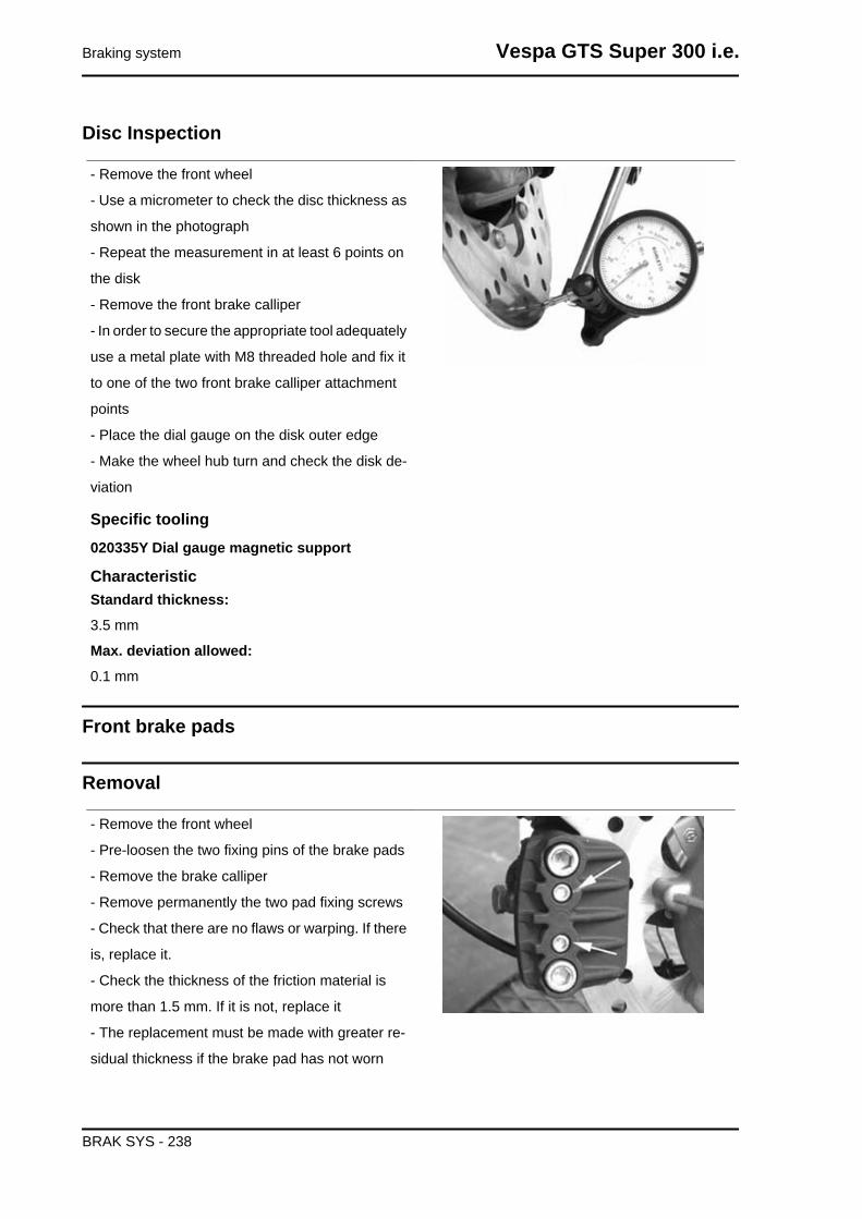
Disc Inspection
- Remove the front wheel
- Use a micrometer to check the disc thickness as
shown in the photograph
- Repeat the measurement in at least 6 points on
the disk
- Remove the front brake calliper
- In order to secure the appropriate tool adequately
use a metal plate with M8 threaded hole and fix it
to one of the two front brake calliper attachment
points
- Place the dial gauge on the disk outer edge
- Make the wheel hub turn and check the disk de-
viation
Specific tooling020335Y Dial gauge magnetic support
CharacteristicStandard thickness:3.5 mm
Max. deviation allowed:0.1 mm
Front brake pads
Removal
- Remove the front wheel
- Pre-loosen the two fixing pins of the brake pads
- Remove the brake calliper
- Remove permanently the two pad fixing screws
- Check that there are no flaws or warping. If there
is, replace it.
- Check the thickness of the friction material is
more than 1.5 mm. If it is not, replace it
- The replacement must be made with greater re-
sidual thickness if the brake pad has not worn
Braking system Vespa GTS Super 300 i.e.
BRAK SYS - 238
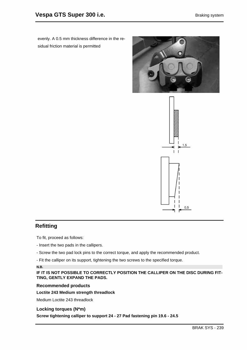
evenly. A 0.5 mm thickness difference in the re-
sidual friction material is permitted
Refitting
To fit, proceed as follows:
- Insert the two pads in the callipers.
- Screw the two pad lock pins to the correct torque, and apply the recommended product.
- Fit the calliper on its support, tightening the two screws to the specified torque.N.B.
IF IT IS NOT POSSIBLE TO CORRECTLY POSITION THE CALLIPER ON THE DISC DURING FIT-TING, GENTLY EXPAND THE PADS.
Recommended productsLoctite 243 Medium strength threadlock
Medium Loctite 243 threadlock
Locking torques (N*m)Screw tightening calliper to support 24 - 27 Pad fastening pin 19.6 - 24.5
Vespa GTS Super 300 i.e. Braking system
BRAK SYS - 239

Rear brake pads
Removal
- Remove the rear brake calliper.
- Remove the snap ring, slide off the pad retention
pin and the clip.
- Remove the brake pads and check there are no
faults or warping. Otherwise, replace them.
- Check the thickness of the friction material is
more than 1.5 mm. If it is not, replace it
- The replacement must be made with greater re-
sidual thickness if the brake pad has not worn
evenly. A 0.5 mm thickness difference in the re-
sidual friction material is permitted
Braking system Vespa GTS Super 300 i.e.
BRAK SYS - 240

Refitting
- Insert the brake pads
- Insert the fixing pin being careful to position the
clip with the ends towards the bleed screw as in
the photo.
- Insert the lock on the bolt and then the protection
cover
N.B.
FAILURE TO RESPECT THE PAD POSITIONING REQUIREMENTS WITH RESPECT TO THE DI-RECTION OF ROTATION COULD COMPROMISE PROPER BRAKE FUNCTIONING AND NOISE-LESSNESS.
Fill
Rear - combined
- Remove the rubber cap from the bleed screw.
- Insert a rubber pipe in the bleed screw to permit
the brake fluid to be recovered.
- With the left-had brake lever, load the system and
bring it up to the required pressure.
- Keeping the left-hand brake lever pulled, loosen
the bleed screw to permit the air in the system to
escape. Then tighten the bleed screw
- Repeat the operation until only brake fluid comes out of the rubber pipe.
- Remove the fluid recovery pipe and refit the rubber cap over the bleed screw.
- Top up the brake fluid to the right level in the reservoir.
If necessary, bleeding can be done using a special vacuum pumpN.B.
Vespa GTS Super 300 i.e. Braking system
BRAK SYS - 241
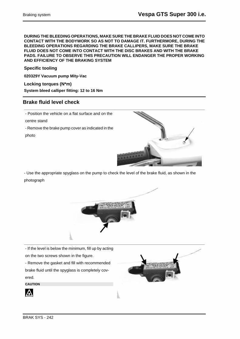
DURING THE BLEEDING OPERATIONS, MAKE SURE THE BRAKE FLUID DOES NOT COME INTOCONTACT WITH THE BODYWORK SO AS NOT TO DAMAGE IT. FURTHERMORE, DURING THEBLEEDING OPERATIONS REGARDING THE BRAKE CALLIPERS, MAKE SURE THE BRAKEFLUID DOES NOT COME INTO CONTACT WITH THE DISC BRAKES AND WITH THE BRAKEPADS. FAILURE TO OBSERVE THIS PRECAUTION WILL ENDANGER THE PROPER WORKINGAND EFFICIENCY OF THE BRAKING SYSTEM
Specific tooling020329Y Vacuum pump Mity-Vac
Locking torques (N*m)System bleed calliper fitting: 12 to 16 Nm
Brake fluid level check
- Position the vehicle on a flat surface and on the
centre stand
- Remove the brake pump cover as indicated in the
photo
- Use the appropriate spyglass on the pump to check the level of the brake fluid, as shown in the
photograph
- If the level is below the minimum, fill up by acting
on the two screws shown in the figure.
- Remove the gasket and fill with recommended
brake fluid until the spyglass is completely cov-
ered.CAUTION
Braking system Vespa GTS Super 300 i.e.
BRAK SYS - 242

MAKE SURE THE BRAKE FLUID DOES NOT GET INTOYOUR EYES OR ON YOUR SKIN OR CLOTHES. IF THISHAPPENS ACCIDENTALLY, WASH WITH WATER.CAUTION
THE BRAKING CIRCUIT FLUID IS HIGHLY CORROSIVE.THEREFORE, WHEN TOPPING UP, AVOID LETTING ITCOME INTO CONTACT WITH THE PAINTED PARTS OFTHE VEHICLE. THE BRAKING CIRCUIT FLUID IS HYGRO-SCOPIC, THAT IS, IT ABSORBS HUMIDITY FROM THESURROUNDING AIR. IF THE HUMIDITY IN THE BRAKINGFLUID EXCEEDS A CERTAIN VALUE, IT WILL LEAD TOINEFFICIENT BRAKING.CAUTIONBRAKE FLUID IS HYGROSCOPIC; THAT IS, IT ABSORBSMOISTURE FROM THE SURROUNDING AIR. IF THE CON-TENT OF MOISTURE IN THE BRAKE FLUID EXCEEDS ACERTAIN VALUE, BRAKING WILL BE INEFFICIENT.
Never use brake liquid in open or partially used containers.
Under standard climatic conditions, replace coolant as indicated in the scheduled maintenance table.
For refitting purposes carry out the removal operations but in reverse order and respect the tightening
torques of the tank cover screws.
Locking torques (N*m)Brake pump reservoir screws 1.5 ÷ 2
Front brake pump
Removal
- Remove the rear handlebar cover.
- Remove the two screws fixing the brake pump to
the handlebar indicated in the photograph
- Remove the oil pipe joint from the pump
- Remove the connector to the stop light switch
Vespa GTS Super 300 i.e. Braking system
BRAK SYS - 243
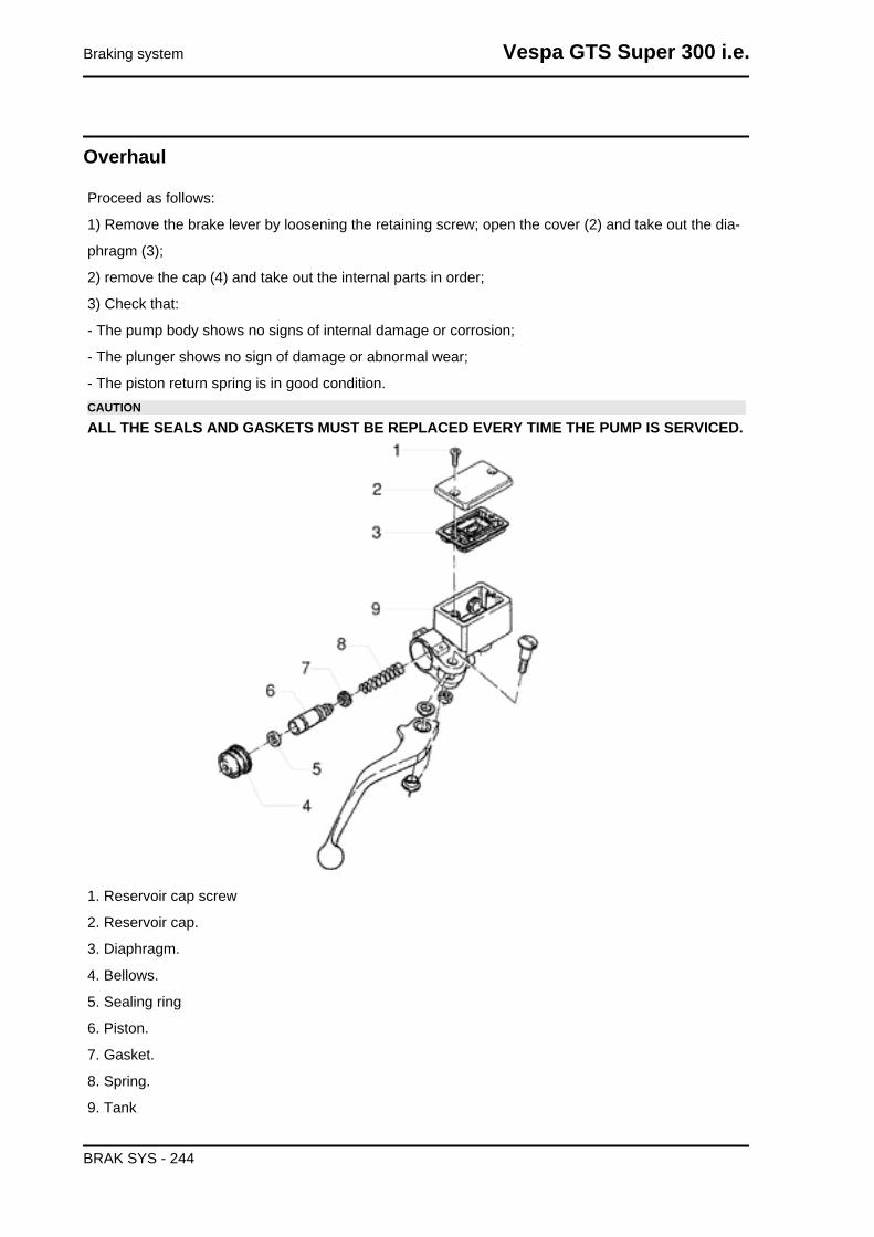
Overhaul
Proceed as follows:
1) Remove the brake lever by loosening the retaining screw; open the cover (2) and take out the dia-
phragm (3);
2) remove the cap (4) and take out the internal parts in order;
3) Check that:
- The pump body shows no signs of internal damage or corrosion;
- The plunger shows no sign of damage or abnormal wear;
- The piston return spring is in good condition.CAUTION
ALL THE SEALS AND GASKETS MUST BE REPLACED EVERY TIME THE PUMP IS SERVICED.
1. Reservoir cap screw
2. Reservoir cap.
3. Diaphragm.
4. Bellows.
5. Sealing ring
6. Piston.
7. Gasket.
8. Spring.
9. Tank
Braking system Vespa GTS Super 300 i.e.
BRAK SYS - 244

Refitting
For refitting, follow the operations in reverse order observing the tightening torque.
Locking torques (N*m)Oil pipe joint to the pump: 20 - 25 Brake pump fixing screws to the handlebar: 7 to 10 Nm
Vespa GTS Super 300 i.e. Braking system
BRAK SYS - 245

INDEX OF TOPICS
COOLING SYSTEM COOL SYS

Circuit diagram
Vespa GTS Super 300 i.e. Cooling system
COOL SYS - 247

Cooling system Vespa GTS Super 300 i.e.
COOL SYS - 248

System bleed
- Start up the engine until the operating tempera-
ture is reached.
- Remove the rubber hood over the bleed valve
- Obtain a rubber tube that is of the right length to
connect the valve to the expansion tank
- Place one end of the pipe on the bleed valve and
the other in the expansion tank
- Loosen the screw by two turns until the commu-
nication hole is revealed with the head as shown
in the picture
- Wait until only coolant comes out of the rubber
pipe so as to eliminate any air bubbles inside the
circuit.
- Tighten the bleed valve respecting the maximum
torque.
Vespa GTS Super 300 i.e. Cooling system
COOL SYS - 249

- Bring the coolant up to the correct level inside the
expansion tank
Locking torques (N*m)Bleed screw 3
Thermostat
Removal
- Remove the helmet compartment.
- Place a + 2.0 l container under the vehicle to col-
lect the coolant.
- Undo the two screws indicated, lift the cover and
remove the thermostat.
Check
1) Visually inspect that the thermostat is not dam-
aged.
2) Fill a metal container with approx. 1 litre of wa-
ter.
Immerse the thermostat, and keep it in the centre
of the container.
Immerse the multimeter temperature probe, and
keep it close to the thermostat.
Heat up the container using the thermal gun.
Cooling system Vespa GTS Super 300 i.e.
COOL SYS - 250
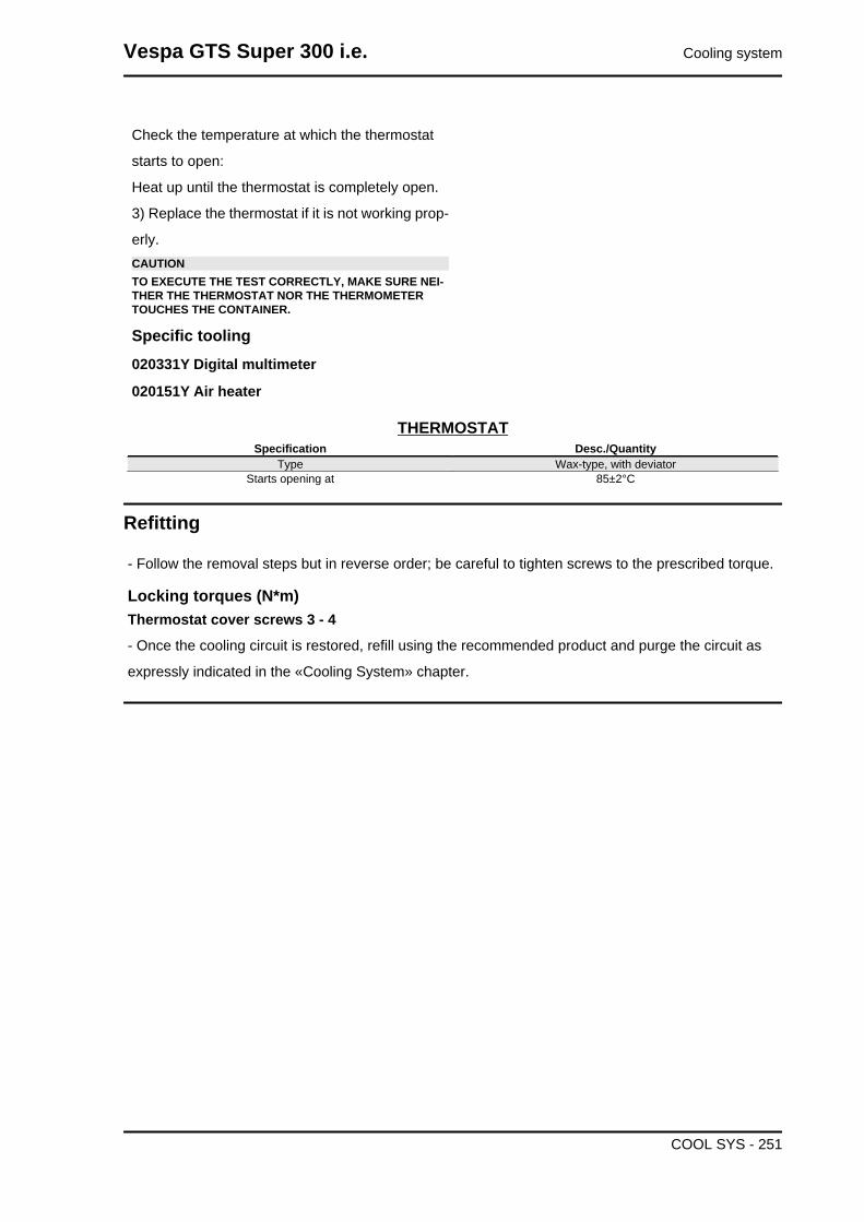
Check the temperature at which the thermostat
starts to open:
Heat up until the thermostat is completely open.
3) Replace the thermostat if it is not working prop-
erly.CAUTIONTO EXECUTE THE TEST CORRECTLY, MAKE SURE NEI-THER THE THERMOSTAT NOR THE THERMOMETERTOUCHES THE CONTAINER.
Specific tooling020331Y Digital multimeter
020151Y Air heater
THERMOSTATSpecification Desc./Quantity
Type Wax-type, with deviatorStarts opening at 85±2°C
Refitting
- Follow the removal steps but in reverse order; be careful to tighten screws to the prescribed torque.
Locking torques (N*m)Thermostat cover screws 3 - 4
- Once the cooling circuit is restored, refill using the recommended product and purge the circuit as
expressly indicated in the «Cooling System» chapter.
Vespa GTS Super 300 i.e. Cooling system
COOL SYS - 251

INDEX OF TOPICS
CHASSIS CHAS

This section è is dedicated to the operations that can be carried out on the vehicle's bodywork.
Seat
- Remove the helmet compartment
- Remove the two screws shown in the photograph
- Remove the saddle
- Remove the helmet compartment
- Remove the 2 nuts indicated in the photograph
- Free the electric cables form the retaining clamps
indicated in the photograph
- Remove the saddle opening transmission cable
- Remove the saddle manual opening transmis-
sion cable.
Vespa GTS Super 300 i.e. Chassis
CHAS - 253

- Remove the electric connector from the saddle
opening actuator
- Remove the two screws shown in the photograph
- Remove the clip from the transmission
- Remove the actuator from the supporting bracket
Rear rack
- Remove the helmet compartment
- Remove the 4 screws indicated in the figure
- Remove the two screws, indicated in the figure,
that fix the luggage rack to the body
Chassis Vespa GTS Super 300 i.e.
CHAS - 254

Rear handlebar cover
- Remove the front handlebar cover
- Undo the 5 screws indicated in the photograph
-Disconnect the odometer cable
-After disconnecting the wiring remove the rear
handlebar.
Instrument panel
- Remove the rear handlebar cover;
- Remove the four screws indicated in the figure
- Remove the instrument panel.
Front handlebar cover
- Remove the rear-view mirrors.
- Remove the front central cover.
- Remove the front screw indicated in the figure.
Vespa GTS Super 300 i.e. Chassis
CHAS - 255

-Undo the 2 screws indicated in the figure;
- Remove the front handlebar cover
- Disconnect the front headlamp connectors
Headlight assy.
- Remove the front handlebar cover.
- Undo the four screws indicated.
- Operate the screw indicated in the figure to re-
move the front turn indicator
Chassis Vespa GTS Super 300 i.e.
CHAS - 256

Knee-guard
- Remove the rear handlebar cover.
- Remove the two screws indicated in the photo-
graph and located on the shield under the grille
- Remove the expansion tank cover and then its
cap
- Remove the central screw inside the glove-box,
indicated in the photograph
- Remove the two screws indicated in the photo-
graph and located below the expansion tank cover
and the left cover respectively
- Remove the shield back plate lower screws, to
the right and left side of the shield back plate, as
indicated in the photograph
Vespa GTS Super 300 i.e. Chassis
CHAS - 257
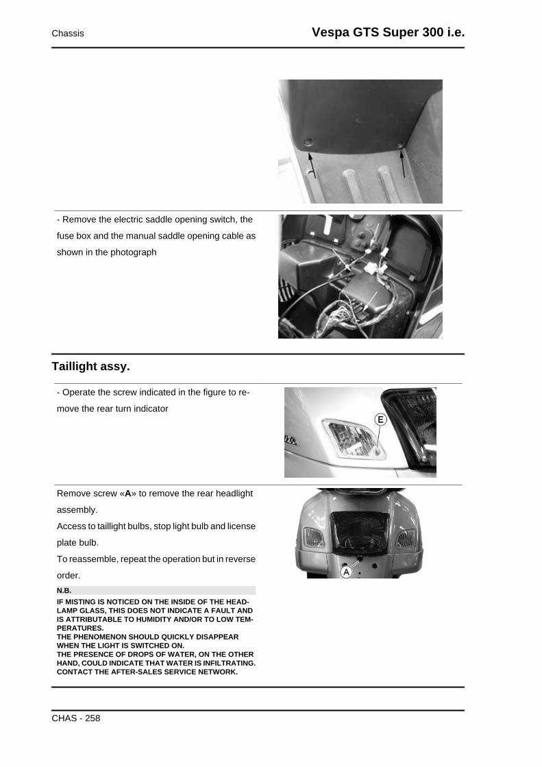
- Remove the electric saddle opening switch, the
fuse box and the manual saddle opening cable as
shown in the photograph
Taillight assy.
- Operate the screw indicated in the figure to re-
move the rear turn indicator
Remove screw «A» to remove the rear headlight
assembly.
Access to taillight bulbs, stop light bulb and license
plate bulb.
To reassemble, repeat the operation but in reverse
order.N.B.IF MISTING IS NOTICED ON THE INSIDE OF THE HEAD-LAMP GLASS, THIS DOES NOT INDICATE A FAULT ANDIS ATTRIBUTABLE TO HUMIDITY AND/OR TO LOW TEM-PERATURES.THE PHENOMENON SHOULD QUICKLY DISAPPEARWHEN THE LIGHT IS SWITCHED ON.THE PRESENCE OF DROPS OF WATER, ON THE OTHERHAND, COULD INDICATE THAT WATER IS INFILTRATING.CONTACT THE AFTER-SALES SERVICE NETWORK.
Chassis Vespa GTS Super 300 i.e.
CHAS - 258

Footrest
- Remove the shield back plate
- Remove the battery compartment cover
- Remove the side fairings
- Remove the central screw located under the bat-
tery compartment cover as indicated in the figure
- Remove the passenger footrests undoing the two
screws indicated in the figure
- Remove the right and left screws fixing the foot-
rest indicated in the figure
- Remove the right and left lower covers as shown
in the figure
Vespa GTS Super 300 i.e. Chassis
CHAS - 259
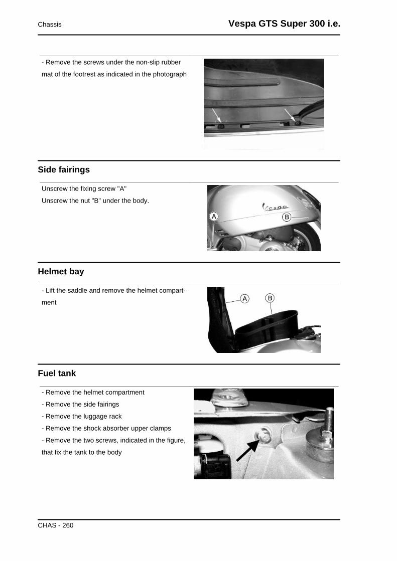
- Remove the screws under the non-slip rubber
mat of the footrest as indicated in the photograph
Side fairings
Unscrew the fixing screw "A"
Unscrew the nut "B" under the body.
Helmet bay
- Lift the saddle and remove the helmet compart-
ment
Fuel tank
- Remove the helmet compartment
- Remove the side fairings
- Remove the luggage rack
- Remove the shock absorber upper clamps
- Remove the two screws, indicated in the figure,
that fix the tank to the body
Chassis Vespa GTS Super 300 i.e.
CHAS - 260

- Remove the screw indicated in the figure that fixes the tank to the body after removing the rear head-
light assembly
- Remove the two turn indicators
- Use a jack to lift the body so that there is enough
space between the vehicle rear side and the en-
gine to slide off the tank
To refit, perform the steps in the reverse direction
to disassembly
Rear central cover
- Remove the four screws indicated in the figure
Vespa GTS Super 300 i.e. Chassis
CHAS - 261
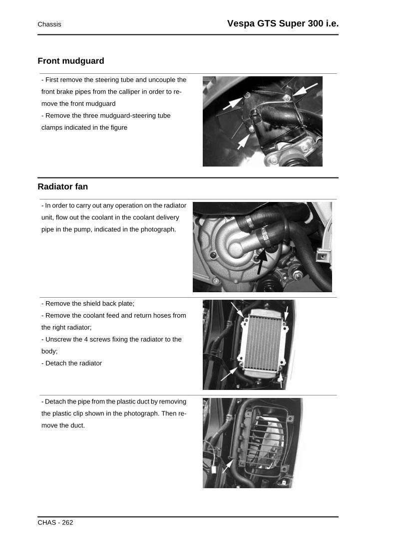
Front mudguard
- First remove the steering tube and uncouple the
front brake pipes from the calliper in order to re-
move the front mudguard
- Remove the three mudguard-steering tube
clamps indicated in the figure
Radiator fan
- In order to carry out any operation on the radiator
unit, flow out the coolant in the coolant delivery
pipe in the pump, indicated in the photograph.
- Remove the shield back plate;
- Remove the coolant feed and return hoses from
the right radiator;
- Unscrew the 4 screws fixing the radiator to the
body;
- Detach the radiator
- Detach the pipe from the plastic duct by removing
the plastic clip shown in the photograph. Then re-
move the duct.
Chassis Vespa GTS Super 300 i.e.
CHAS - 262
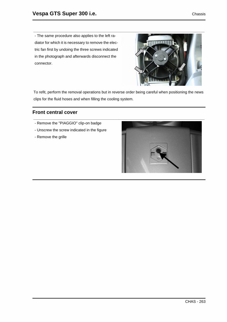
- The same procedure also applies to the left ra-
diator for which it is necessary to remove the elec-
tric fan first by undoing the three screws indicated
in the photograph and afterwards disconnect the
connector.
To refit, perform the removal operations but in reverse order being careful when positioning the news
clips for the fluid hoses and when filling the cooling system.
Front central cover
- Remove the "PIAGGIO" clip-on badge
- Unscrew the screw indicated in the figure
- Remove the grille
Vespa GTS Super 300 i.e. Chassis
CHAS - 263

INDEX OF TOPICS
PRE-DELIVERY PRE DE
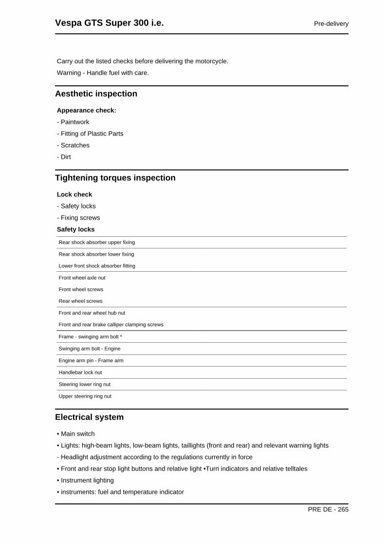
Carry out the listed checks before delivering the motorcycle.
Warning - Handle fuel with care.
Aesthetic inspection
Appearance check:
- Paintwork
- Fitting of Plastic Parts
- Scratches
- Dirt
Tightening torques inspection
Lock check
- Safety locks
- Fixing screws
Safety locks
Rear shock absorber upper fixing
Rear shock absorber lower fixing
Lower front shock absorber fitting
Front wheel axle nut
Front wheel screws
Rear wheel screws
Front and rear wheel hub nut
Front and rear brake calliper clamping screws
Frame - swinging arm bolt *
Swinging arm bolt - Engine
Engine arm pin - Frame arm
Handlebar lock nut
Steering lower ring nut
Upper steering ring nut
Electrical system
• Main switch
• Lights: high-beam lights, low-beam lights, taillights (front and rear) and relevant warning lights
- Headlight adjustment according to the regulations currently in force
• Front and rear stop light buttons and relative light •Turn indicators and relative telltales
• Instrument lighting
• instruments: fuel and temperature indicator
Vespa GTS Super 300 i.e. Pre-delivery
PRE DE - 265
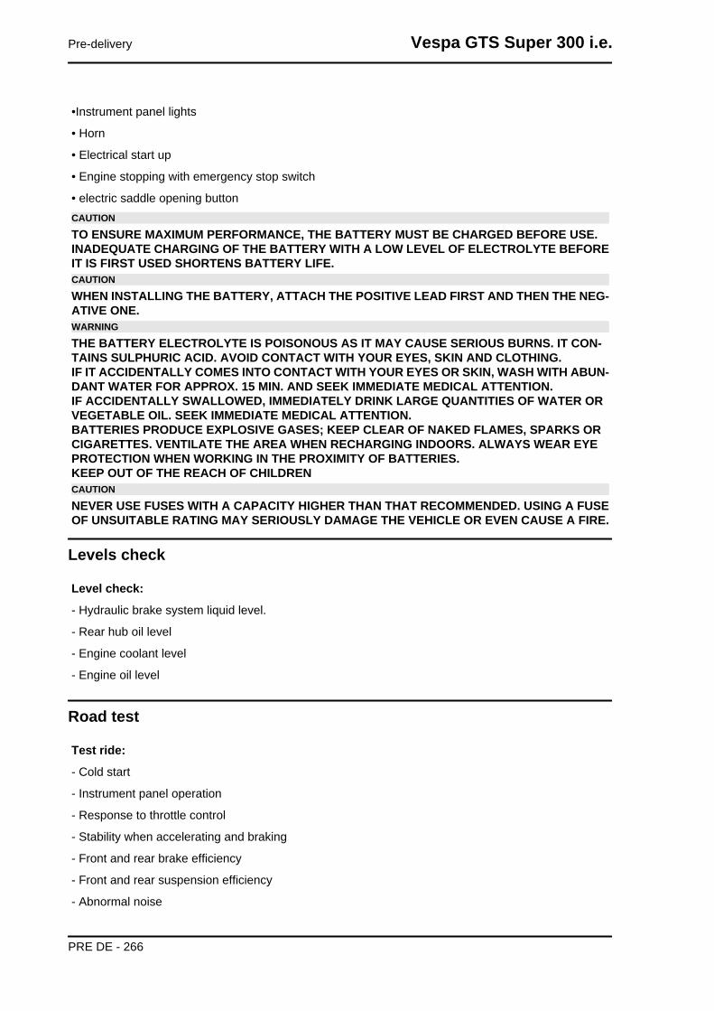
•Instrument panel lights
• Horn
• Electrical start up
• Engine stopping with emergency stop switch
• electric saddle opening buttonCAUTION
TO ENSURE MAXIMUM PERFORMANCE, THE BATTERY MUST BE CHARGED BEFORE USE.INADEQUATE CHARGING OF THE BATTERY WITH A LOW LEVEL OF ELECTROLYTE BEFOREIT IS FIRST USED SHORTENS BATTERY LIFE.CAUTION
WHEN INSTALLING THE BATTERY, ATTACH THE POSITIVE LEAD FIRST AND THEN THE NEG-ATIVE ONE.WARNING
THE BATTERY ELECTROLYTE IS POISONOUS AS IT MAY CAUSE SERIOUS BURNS. IT CON-TAINS SULPHURIC ACID. AVOID CONTACT WITH YOUR EYES, SKIN AND CLOTHING.IF IT ACCIDENTALLY COMES INTO CONTACT WITH YOUR EYES OR SKIN, WASH WITH ABUN-DANT WATER FOR APPROX. 15 MIN. AND SEEK IMMEDIATE MEDICAL ATTENTION.IF ACCIDENTALLY SWALLOWED, IMMEDIATELY DRINK LARGE QUANTITIES OF WATER ORVEGETABLE OIL. SEEK IMMEDIATE MEDICAL ATTENTION.BATTERIES PRODUCE EXPLOSIVE GASES; KEEP CLEAR OF NAKED FLAMES, SPARKS ORCIGARETTES. VENTILATE THE AREA WHEN RECHARGING INDOORS. ALWAYS WEAR EYEPROTECTION WHEN WORKING IN THE PROXIMITY OF BATTERIES.KEEP OUT OF THE REACH OF CHILDRENCAUTION
NEVER USE FUSES WITH A CAPACITY HIGHER THAN THAT RECOMMENDED. USING A FUSEOF UNSUITABLE RATING MAY SERIOUSLY DAMAGE THE VEHICLE OR EVEN CAUSE A FIRE.
Levels check
Level check:
- Hydraulic brake system liquid level.
- Rear hub oil level
- Engine coolant level
- Engine oil level
Road test
Test ride:
- Cold start
- Instrument panel operation
- Response to throttle control
- Stability when accelerating and braking
- Front and rear brake efficiency
- Front and rear suspension efficiency
- Abnormal noise
Pre-delivery Vespa GTS Super 300 i.e.
PRE DE - 266

Static test
Static control after the test ride:
• Hot engine restart
• Minimum seal (turning the handlebar)
• Uniform steering rotation
• Possible losses
• electric radiator fan operationCAUTION
CHECK AND ADJUST TYRE PRESSURE WITH TYRES AT AMBIENT TEMPERATURE.CAUTION
NEVER EXCEED THE RECOMMENDED INFLATION PRESSURES AS TYRES MAY BURST.
Functional inspection
Functional Checks:
• Hydraulic braking system: lever travel
• Clutch: proper functioning check
• Engine: proper general functioning and no abnormal noise check
• Other: papers check, chassis and engine number check, tools and equipment, licence plate fitting,
lock check, tyre pressure check, rear-view mirror and any accessory fitting
Specific operations for the vehicleN.B.Install the rear retro-reflector up to the indicated frame, belowthe number plate located in the provided package:VESPA GTS 300:ZAPM4520000086963VESPA GTS 300 ABS:ZAPM4520200003098From the next frame on, this is not necessary as the vehicle isequipped with a light with integrated retro-reflector.
Vespa GTS Super 300 i.e. Pre-delivery
PRE DE - 267

Install the underbody caps as shown in the figure.
Pre-delivery Vespa GTS Super 300 i.e.
PRE DE - 268

AABS: 74, 228Air filter: 51
BBattery: 72, 83, 93, 94Brake: 233–236, 238, 240, 242, 243Brake fluid: 242
CChecks: 78
EElectric: Engine oil: 52
FFuel: 181, 188, 260Fuses: 91
HHeadlight: 57, 256Horn: 87Hub oil: 50
IIdentification: 8Instrument panel: 255
MMaintenance: 7, 47
OOil filter: 53
RRecommended products:
SShock absorbers: 224Spark plug: 49Stand: 226Suspension: 60, 61Switch:

TTank: 260Transmission: 10, 59, 117, 131Turn indicators: 76Tyre pressure: Tyres: 15
VVehicle: 8, 109, 110, 267
Copyright © 2022 FDOKUMEN