WORKSHOP MANUAL - Vespa Club Polska
243
WORKSHOP MANUAL LX 150 4T USA
-
Upload
khangminh22 -
Category
Documents
-
view
0 -
download
0
Transcript of WORKSHOP MANUAL - Vespa Club Polska

WORKSHOP MANUAL
LX 150 4T USA

WORKSHOP MANUAL
LX 150 4T USA
The descriptions and illustrations supplied in this publication are not binding. PlAGGlO therefore reserves the right to make any changes to pieces, parts or accessory supplies, which it believes to be appropriate for improvement purposes or any requirement of a constructive or commercial nature, at any time, without the obligation to up-dating this publication before time, the essential characteristics
of the type described and illustrated here remaining valid. Not all versions reported in this publication are available in all Countries. The availability of single
versions should be checked at the official Piaggio sales network. "O Copyright 2005 - PlAGGlO & C. S.p.A. Pontedera. All rights reserved. No part of this publication
may be reproduced." PlAGGlO & C. S.p.A. - Q.C.S.1 After Sale Service V.le Rinaldo Piaggio, 23 - 56025 Pontedera (PI)
www.piaggio.com

WORKSHOP MANUAL LX 150 4T USA
This workshop manual has been drawn up by Piaggio & C. Spa to be used by the workshops of Piaggio-Gilera dealers. This manual is addressed to Piaggio service mechanics who are supposed to have a basic knowledge of mechanics principles and of vehicle fixing techniques and procedures. Any important changes made to the vehicles or to specific fixing operations will be promptly reported by updates to this manual. Nevertheless, no fixing work can be satisfactory if the necessary equipment and tools are unavailable. It is therefore advisable to read the sections of this manual relating to specific tools, along with the specific tool catalogue.
N.B. Provides key information to make the procedure easier to understand and carry out.
CAUTION Refers to specific procedures to carry out for preventing damages to the vehicle.
WARNING Refers to specific procedures to carry out to prevent injuries to the repairer.
Personal safety Failure to completely observe these instructions will result in serious risk of personal injury.
Safeguarding the environment Sections marked with this symbol indicate the correct use of the vehicle to prevent damaging the environment.
Vehicle intactness The incomplete or non-observance of these regulations leads to the risk of serious damage to the vehicle and sometimes even the invalidity of the guarantee.


CHARACTERISTICS
TOOLING
MAINTENANCE
TROUBLESHOOTING
ELECTRICAL SYSTEM
ENGINE FROM VEHICLE
ENGINE
SUSPENSIONS
BRAKING SYSTEM
CHASSIS
PRE-DELIVERY
TIME


Characteristics LX 150 4T USA
Rules
This section describes general safety rules for any interventions to be performed on the vehicle.
Safety rules
- Should it be necessary to keep the engine running while servicing, make sure that the area or room
is well ventilated, and use special exhaust fans, if required. Never let the engine running in closed
rooms. In fact, exhaust gases are toxic.
- The battery electrolyte contains sulphuric acid. Protect your eyes, cloths and skin. Sulphuric acid is
highly corrosive; in the event of contact with your eyes or clothes, rinse thoroughly with water and
consult a doctor immediately.
- The battery produces hydrogen, a gas that can be highly explosive. Do not smoke and avoid sparks
and flames when close to the battery, especially during recharge.
- Fuel is highly flammable, and in some conditions it can be explosive. Do not smoke in the working
area, and avoid free flames or sparks.
- Clean the brake pads in a well ventilated environment, directing the compressed air jet so as to not
intake the dust produced by the wear of the friction material. Even though the latter contains no as-
bestos, dust inhalation is harmful.
Maintenance rules
- Use original PlAGGlO spare parts and lubricants recommended by the Manufacturer. Non-original
or non-conforming spares may damage the vehicle.
- Use only the specific tools designed for this vehicle.
-Always use new gaskets, sealing rings and split pins upon reassembly.
- After removal, clean the components using non-flammable or low fire-point solvent. Lubricate all
working surfaces before reassembly, except for conical couplings.
-After reassembly, check that all components have been installed properly and that they are in good
working order.
- For removal, overhaul and reassembly operations use only tools provided with metric measures.
Metric bolts, nuts and screws are not interchangeable with coupling members with English measure-
ment. Using improper coupling members and tools may impair the vehicle.
- Should any interventions to the vehicle electric system be required, check that the electrical connec-
tions - especially earth and battery connections - have been implemented properly.
Vehicle identification
CHAR - 2

LX 150 4T USA Characteristics
VEHICLE IDENTIFICATION
Specification Desc.lQuantity
Chassis prefix ZAPM 428 F5
engine prefix M442M+1001
Dimensions and mass
DIMENSIONS AND WEIGHT
Specification Desc.lQuantity
Curbside weight l l O k 5 k g
Maximum height 1140 mm
Width 740 mm
Wheelbase 1280 mm
Length 1800 mm
Engine
Specification
ENGINE
Desc.lQuantity
Engine Single cylinder 4-stroke Piaggio LEADER
Timing system Single Over-Head Cam shaft (SOHC), 2 valves
Valve play suction 0,10 exhaust: 0,15
Bore per stroke 62,6 x 48,6 mm
Dry weight 150,46 cm3
Compression ratio 10.5 : 1
Carburettor KElHlN CVEK26
Idling - 1600 + 1800 r.p.m.
Starter system Electric
Max power 1 1,6 CV at 7750 rpm
Cooling Forced air.
CHAR - 3

Characteristics LX 150 4T USA
Transmission
TRANSMISSION
Specification DescJQuantity
Trasmission With automatic expandable pulley variator, trapezoidal belt, automatic clutch, gear reducer
and transmission compartment with forced circu- lation.
Capacities
CAPACITY
Specification Desc.lQuantity
Engine oil - 1000 cc
Rear oil hub - 100 cc
Fuel tank capacity " 8.5 litres (including 2 1 reserve)
Electrical system
ELECTRICAL SYSTEM
Specification Desc.lQuantity
Starter system Electric
Spark Champion RGGYC- NGK CR7EB
Frame and suspensions
CHASSIS AND SUSPENSION
Specification DescJQuantity
Frame Structural frame in pressed sheet steel
Steering and suspensions Steering column tube pivoted on front wheel hub; helical spring suspension and hydraulic double-ef-
fect shock absorbers; rear with hydraulic double-ef- fect shock absorber and adjustable coaxial spring
in the preloading on 4 positions.
Brakes
BRAKES
Specification Desc.lQuantity
Front brake 0 200 mm disc (hydraulically controlled via a lever on RHS of handlebars) with fixed calliper.
CHAR - 4

LX 150 4T USA Characteristics
Specification Desc.lQuantity
Rear brake 0 1 10 mm drum
Wheels and tyres
WHEELS AND TYRES
Specification Desc.lQuantity
Front wheel rim Die-cast aluminium alloy 2.50~11"
Front tyre Tubeless 1 10170-1 1"
Rear wheel rim Die-cast aluminium alloy 3.00~10"
Rear tyre Tubeless 120170-1 0"
Tyre pressure (front wheel) 1,6 bar
Tyre pressure rear wheel 2 bar
Tyre pressure (rear wheel driver and passenger) 2,3 bar
Secondary air
To reduce the amount of polluting emissions, this T 1 vehicle is equipped with a catalytic converter. \Tp- In order to facilitate the catalysis process, extra wh kb @&,,, i , 1
oxygen is supplied via a Secondary Air System
(SAS). . \ i l
'$1 --- < Such system allows to add oxygen to the unburnt
gases before the catalytic converter, thus improv-
ing the efficiency of the catalyser and hence the
reaction process.
Air is added through an intake duct on the cylin-
der head, after being depurated by black filter.
The system is equipped with a shut-off valve
which engages during deceleration, so to avoid
undesired noise.
To ensure the SAS is always working correctly, it
is necessary to have it checked by an Author-
ised Piaggio Service Station every 12,000 Km
(see the Maintenance Operations section), so that
the filters may be thoroughly cleaned.
CHAR - 5

Characteristics LX 150 4T USA
The operation consists of cleaning the filtering
elements with water and neutral detergent and
then drying them with a clean cloth and light jets
of compressed air.
SHOULD YOU REQUIRE ANY ASSISTANCE, CON- TACT YOUR NEAREST AUTHORISED PlAGGlO DEALER.
Carburettor
150cc Version
Kehin
CALIBRATION CARBURETOR
Specification DescJQuantity
TY pe CVEK 26
Throttle valve diameter 0 26,5
Choke diameter 0 26,4
Adjustment marking 265A
Maximum thrust 82
Maximum air thrust (on body) 85
Tapered pin stamping NELA
Gas valve spring 130 + 180 gr.
Minimum jet 35
Minimum air thrust (on body) 150
Initial minimum mixture screw opening 1 %
Starter jet 42
Starter air thrust (on body) 0 1,5
Starter pin stroke 10 mm (a 24")
Choke resistor 20 Ohm (a 24")
Tightening Torques
LUBRICATION
CHAR - 6

LX 150 4T USA Characteristics
Name Torque in Nm
Hub oil drainage cap 15 + 17
Oil filter 4 + 6
Oil pump cover screws 5 + 6
Oil pump screw tightening torque 5 + 6 N m
Pump drive pulley screw 10 + 14
Chain cover screws 4 + 6
Oil pan screws 10 + 14
Minimum oil pressure sensor 12 + 14
Blow-by recovery duct fastening screws: 3 - 4
CYLINDER HEAD
Name Torque in Nm
Ignition spark plug 12 + 14
Head cover screw 11 + 13
Head to cylinder set nuts (*) 28 + 30
Head set screws (external) 11 + 13
Start up mass screws 7 + 8,5
Magneto housing screw 1 + 2
Magneto side air duct screw 3 + 4
De-compressor balance weight fixing 7 + 8,5
Camshaft pulley screw: 12 + 14 Nm
Timing chain tightener sliding block screws 10 + 14
Start up mass bell screws 11 + 15
Tightener screws 11+13 Nm
Timing chain tensioner central screw: 5 + 6 N m
Camshaft retain plate screw 5 + 6
Exhaust pipelcylinder head fixing nut. 16 + 18
Suction manifold screw on head
TRANSMISSION
Name
11 + 13
Torque in Nm
Driving pulley screw 75 + 83
Transmission cover screw 11 + 13
Driven pulley axis (") 54 + 60
Rear hub cover screw 24 + 27
Clutch assembly nut on driven pulley 45 + 50
CHAR - 7

Characteristics LX 150 4T USA
FLYWHEEL
Name Torque in Nm
Flywheel fan screws 3 +4 N.m
Stator cover screws (") 3 + 4
Flywheel nut 52 + 58
Pick-up screw 3+ 4
CRANKCASE AND DRIVING SHAFT
Name Torque in Nm
Engine crankcase inside head screws (transmission side half shaft)
Oil filter union on crankcase 27 + 33
Rear brake shaft set screw 11 + 13
Engine crankcase coupling screws 11 + 13
Prefilter cap 24 + 30
Starter motor fixing screw: 11 + 13 Nm
Muffler to crankcase set screws 24 + 27
Engine oil drainage cap 24 + 30
STEERING UNlT
Name Torque in Nm
Steering upper ring nut 35 + 40
Steering lower ring nut 12 + 14
Handlebar fastening screw 50 + 55
CHASSIS UNlT
Name Torque in Nm
Frame - swing arm bolt 44 + 52
rocker arm pin - engine 33 + 41
Centre stand pin 32 + 40
Bolt mounting rocker arm silent-block 33 + 41
FRONT SUSPENSION
Name Torque in Nm
Shock absorber upper nut 20 + 30
Front wheel spindle nut 75 + 90
Shock absorber upper bracket bolt 20 + 25
Wheel rim screw 20 + 25
Shock absorber lower bolts (") 20 + 27
CHAR - 8

LX 150 4T USA Characteristics
FRONT BRAKE
Name Torque in Nm
Pump-tube oil connection 8 + 1 2
Tube-caliper oil connection 20 + 25
Screw fixing the caliper to the support 20 + 25
Brake disc screw 5 + 6,5
Oil bleeder valve (on caliper) 10 + 12
Handlebar to pump 7 + 1 0
REAR SUSPENSION
Name Torque in Nm
Rear wheel axle 104 + 126
Shock absorber bottom fixing 33 + 41
Shock absorber/chassis nut: 20 - 25 N.m
Overhaul data
Assembly clearances
Cylinder - piston assy.
COUPLING BETWEEN PISTON (ASSO-WERKE) AND CYLINDER
Name Play Initials Cylinder Piston Play on fitting
Coupling <P A 62,580 + 62,533 + 0,040 + 0,054 62,587 62,540
Coupling <I> B 62,587 + 62,540 + 0,040 + 0,054 62,594 62,547
Coupling <I> C 62,594 + 62,547 + 0,040 + 0,054 62,601 62,554
Coupling <P D 62,601 + 62,554 + 0,040 + 0,054 62,608 62,561
Compression <I> A I 62,780 + 62,733 + 0,040 + 0,054 segment I st in- 62,787 62,740
crease
Compression <P segment I st in-
crease
Compression <P C1 62,794 + 62,747 + 0,040 + 0,054 segment I st in- 62,801 62,754
crease
CHAR - 9

Characteristics LX 150 4T USA
Name Play Initials Cylinder Piston Play on fitting
Compression <I> D l 62,801 + 62,754 + 0,040 + 0,054 segment 1st in- 62,808 62,761
crease
Compression <P A2 62,980 + 62,933 + 0,040 + 0,054 segment 2st in- 62,987 62,940
crease
Compression <I> B2 62,987 + 62,940 + 0,040 + 0,054 segment 2st in- 62,994 62,947
crease
Compression <I> C2 62,994 + 62,947 + 0,040 + 0,054 segment 2st in- 63,001 62,954
crease
Compression <I> D2 63,001 + 62,954 + 0,040 + 0,054 segment 2st in- 63,008 62,961
crease
Compression <I> A3 63,180 + 63,133 + 0,040 + 0,054 segment 3st in- 63,187 63,140
crease
Compression <I> B3 63,187 + 63,140 + 0,040 + 0,054 segment 3st in- 63,194 63,147
crease
Compression <I> C3 63,194 + 63,147 + 0,040 + 0,054 segment 3st in- 63,201 63,154
crease
Compression <I> D3 63,201 + 63,154 + 0,040 + 0,054 segment 3st in- 63,208 63,161
crease
COUPLING BETWEEN PISTON (RIGHT WAY! AND CYLINDER
Name Play Initials Cylinder Piston Play on fitting
Coupling <I> A 62,580 + 62,541 + 0,032 + 0,046 62,587 62,548
Coupling <I> B 62,587 + 62,548 + 0,032 + 0,046 62,594 62,555
Coupling <I> C 62,594 + 62,555 + 0,032 + 0,046 62,601 62,562
Coupling <I> D 62,601 + 62,562 + 0,032 + 0,046 62,608 62,569
Piston rings
PISTON RINGS
CHAR - 10

LX 150 4T USA Characteristics
Name Description Dimensions Initials Quantity
Compression lining 62 .6~1 A 0.1 5 + 0.30
Scraper ring lining 62 .6~1 A 0.20 + 0.40
Scraper ring lining 62.6x2.5 A 0.20 + 0.40
Compression lining 62 .8~1 A 0.1 5 + 0.30 I " greater
Scraper ring lining 62 .8~1 A 0.20 + 0.40 I " greater
Scraper ring lining I " greater
Compression lining 2" greater
Scraper ring lining 2" greater
Compression lining 2" greater
Compression lining 3" greater
Compression lining 3" greater
Compression lining 3" greater
Crankcase - crankshaft - connecting rod
AXIAL PLAY BETWEEN CRANKSHAFT AND ROD
Name Description Dimensions Initials Quantity
Half shaft trans- mission side
Half shaft flywheel side
Connecting rod 18 -0,lO -0,15 C 0,20 + 0,50
CHAR- 11

Characteristics LX 150 4T USA
Name Description Dimensions Initials Quantity
Crank pin length 51,400 E
AXIAL PLAY BETWEEN CRANKSHAFT AND BENCH SEMIBEARINGS
Name Description Dimensions Initials Quantity
Crankshaft category 1 28,998 + 29,004
Crankshaft category 2 29,004 + 29,010
Carter Class 1 32,953 + 32,959
Carter Class 2 32,959 + 32.965
Half crankshaft bearing
Type B - blue 1,973 + 1,976
Half crankshaft bearing
Type C - yellow 1,976 + 1,979
Half crankshaft Type E - green 1,979 + 1,982 bearing
Crankshaft 1 cat- E - E
egory 1
Crankshaft 1 cat-
egory 2
C - C
Crankshaft 2 cat-
egory 1
C - C
Crankshaft 2 cat-
egory 2
CrankshaWcrankcase axial play: 0,15 + 0,40
CHAR - 12

LX 150 4T USA Characteristics
Slot packing system
- Temporarily fit the cylinder on the piston, without the base gasket.
- Fit a comparator on the specific device
- Reset the comparator on an inspection surface with an average preload of 5 mm for example Keep-
ing the reset position, fit the device on the cylinder and lock it with 2 nuts as shown in the figure.
- Turn the crankshaft until the upper dead centre point (inversion point of the comparator rotation).
- Calculate the difference between the two measurements: using the table below find the thickness of
the cylinder base gasket to be used for reassembly. Correct identification of the thickness of the cyl-
inder base gasket helps keep the correct compression ratio.
- Remove the specific device and cylinder.
Characteristic
Compression ratio
10.5 : 1
PACKING SYSTEM
Specification DescJQuantity
Measured dimension 1 + 1, l
Base gasket thickness 0,8 & 0,05
Measured dimension 1, l + 1,3
Base gasket thickness 0,6 k 0,05
Measured dimension 1,3 + 1,4
Base gasket thickness 0,4 k 0,05
Products
TABLE OF RECOMMENDED PRODUCTS
Product Description Specifications
TUTELA MATRYX MOT0 Oil for rear hub Oil synthetic multidegree SAE RIDER 75\1\1185 API GL4
CHAR - 13

Characteristics LX 150 4T USA
Product Description Specifications
SELENIA HI Scooter 4 Tech Oil for flexible transmission lub- Oil for four stroke motors rication (brake, acceleration con-
trol, km counter)
SELENIA Air Filter Oil Oil for air filter sponge Mineral oil with specific additive for ingreasing the IS0 VG 150
SELENIA HI Scooter 4 Tech Engine oil Synthetic oil SAE 5Wl40 that passes the API SG specification.
JOTA 3 FS Speedometer transmission Lithium soap grease NLGl 33
TUTELA TOP 4 Brake fluid Synthetic fluid SAE J1703, NHTSA 116 DOT 4, IS0 4925
MONTBLANC MOLYBDENUM Grease for driven pulley shaft Molybdenum bisulphide grease GREASE compensating ring and mobile
driven pulley sliding seat
TUTELA ZETA 2 Grease for steering bearings Lithium soap and zinc oxide and swing arm pin seats and grease NLG12
driven pulley spring supporting surface (pulley side only)
TUTELA TPI Grease for brake control lever, NLGl 1-2 calcium soap based
gas white spray grease
CHAR - 14


Tooling LX 150 4T USA
TOOLS
Stores code Description
001 330Y Steering seat installer, to be fit- ted with parts: 001 330Y009-For lower seat, 001 330Y013-For up-
mm
uu 14e1 r u 13 15-mm pliers
7
Engine support
TOOL - 2

LX 150 4T USA Tooling
Stores code Description
Drift for removing thrust rings from steering head tube
020055Y Steering tube ring nut spanner -- .
Crankshaft aligning tool
Support for air heater "METABO HG 150012"
Air heater "METABO HG 150012"
Oil pressure gauge
TOOL - 3

Tooling LX 150 4T USA
Stores code Description
Crankcase detachment plate Q
Protective shelth
Piston band clamps (Engine 125cc)
Valve sealing ring drift
Pump MITYVAC
TOOL - 4

LX 150 4T USA Tooling
Stores code Description
Timing light for two- and four- stroke engines
Digital multimeter
020332Y Digital rpm counter
Single battery charger .-c --
IF
TOOL - 5

Tooling LX 150 4T USA
Stores code Description
Multiple battery charger
? - - *
Magnetic stand and comparator
020357Y 32 x 35 mm adaptor
42 x 47 mm hub bearing fitting adaptor
020360Y 52 x 55 mm adaptor
20mm guide
25 mm guide
TOOL - 6

LX 150 4T USA Tooling
Stores code Description
020375Y Adapter 28 x 30 mm
Handle for punches
Bushing (valve remc-.I
Multimeter adapter (Peak voltage measurement)
15 mm guide
TOOL - 7

Tooling LX 150 4T USA
Stores code Description
28-mm guide - Hub bearing as- sembly
driven pulley stop key
Driven pulley roller casing drift
Flywheel-side oil guard punch &
Piston fitting fork
TOOL - 8
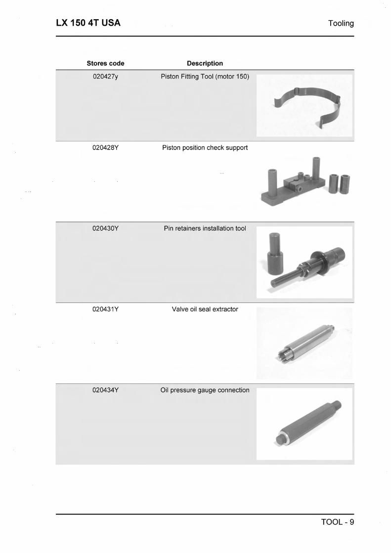
LX 150 4T USA Tooling
Stores code Description
Piston Fitting Tool (motor 150)
Piston position check support
r
Pin retainers installation tool I
Valve oil seal extractor
Oil pressure gauge connection
TOOL - 9

Tooling LX 150 4T USA
Stores code Description
Driven half pulley spring com- pressor tool
020565Y Compass flywheel stop spanner
Transmission-side oil guard punch
494929 Exhaust gas analyser
TOOL - 10


Maintenance LX 150 4T USA
Maintenance chart
EVERY 2 YEARS
Action
Brake fluid - Change
EVERY 3000 KM
Action
Engine Oil - Level ChecWop up
AT 1000 KM 0 4 MONTH
Action
Engine oil - Replacement
Hub Oil - Replacement
Oil filter (net) - cleaning
Idling speed (*) - Adjustment
Acceleration command - Adjustment
Steering - Adjust
Brake levers - Grease
Brake pads - Check condition + wear
Brake fluid level - Check
Nuts, bolts and fasteners - Check
Electrical system and battery - Check
Tires-inflation and wear - Check
Vehicle and brake test - Road test
(*) See section ((Adjusting the idle speed))
AT 6000 KM OR 12 MONTH. 18000 KM. 54000 KM
Action
Engine oil - Replacement
Hub oil level - Check
Spark pluglelectrode gap - Check
Air Filter - Cleaning
Oil filter - Replacement
Oil filter (net) - cleaning
Valvle play 125 - recording
Variator rollers and shoes - inspection

LX 150 4T USA Maintenance
Action
Transmission Belt - Check
Brake pads - Check condition + wear
Brake fluid level - Check
Electrical system and battery - Check
Centre stand - grease
Tires-inflation and wear - Check
Vehicle and brake test - Road test
AT 12000 KM OR 24 MONTHS AND AT 60000 KM 160'
Action
Engine oil - Replacement
Hub oil level - Check
Air Filter - Cleaning
Oil filter - Replacement
Oil filter (net) - cleaning
Spark plug - Replace
Idling speed (*) - Adjustment
Acceleration command - Adjustment
Variator rollers and shoes - replacement
Transmission Belt - Replacemen
Speedometer cable - Grease
Steering - Adjust
Brake levers - Grease
Brake pads - Check condition + wear
Brake fluid level - Check
Transmissions - Lubricate
Nuts, bolts and fasteners - Check
Suspensions - Check
Electrical system and battery - Check
Headlight - Adjust
Centre stand - grease
Secundary filter air - cleaning
Tires-inflation and wear - Check
Vehicle and brake test - Road test
MAIN - 3

Maintenance LX 150 4T USA
(*) See section ((Adjusting the idle speed))
AT 24000 KM AND AT 48000 KM
Action
Engine oil - Replacement
Hub Oil - Replacement
Air Filter - Cleaning
Oil filter - Replacement
Oil filter (net) - cleaning
Spark plug - Replace
Idling speed (*) - Adjustment
Acceleration command - Adjustment
Variator rollers and shoes - replacement
Transmission Belt - Replacemen
Ventilation system cylinder - cleaning
Speedometer cable - Grease
Steering - Adjust
Brake levers - Grease
Brake pads - Check condition + wear
Brake fluid level - Check
Transmissions - Lubricate
Nuts, bolts and fasteners - Check
Suspensions - Check
Electrical system and battery - Check
Headlight - Adjust
Tires-inflation and wear - Check
Secundary filter air - cleaning
Centre stand - grease
Vehicle and brake test - Road test
(*) See section ((Adjusting the idle speed))
AT 30000 KM. AT 42000 KM AND AT 66000 KM
Action
Engine oil - Replacement
Hub oil level - Check
MAIN - 4

LX 150 4T USA Maintenance
Action
Spark pluglelectrode gap - Check
Air Filter - Cleaning
Oil filter - Replacement
Oil filter (net) - cleaning
Variator rollers and shoes - Check
Transmission Belt - Check
Brake pads - Check condition + wear
Brake fluid level - Check
Electrical system and battery - Check
Centre stand - grease
Tires-inflation and wear - Check
Vehicle and brake test - Road test
300' AT 36000 KM
Action
Engine oil - Replacement
Hub Oil - Replacement
Spark plug - Replace
Air Filter - Cleaning
Oil filter - Replacement
Oil filter (net) - cleaning
Valvle play 125 - recording
Idling speed (*) - Adjustment
Acceleration command - Adjustment
Variator rollers and shoes - replacement
Transmission Belt - Replacemen
Speedometer cable - Grease
Steering - Adjust
Brake levers - Grease
Brake pads - Check condition + wear
Brake fluid level - Check
Braking circuit hose - Replacement
Transmissions - Lubricate
Nuts, bolts and fasteners - Check
MAIN - 5

Maintenance LX 150 4T USA
Action
Suspensions - Check
Electrical system and battery - Check
Headlight - Adjust
Secundary filter air - cleaning
Centre stand - grease
Tires-inflation and wear - Check
Vehicle and brake test - Road test
(*) See section ((Adjusting the idle speed))
Action
Engine oil - Replacement
Hub Oil - Replacement
Spark plug - Replace
Air Filter - Cleaning
Oil filter - Replacement
Oil filter (net) - cleaning
Valvle play 125 - recording
Idling speed (*) - Adjustment
Acceleration command - Adjustment
Variator rollers and shoes - replacement
Transmission Belt - Replacemen
Speedometer cable - Grease
Steering - Adjust
Cylinder cooling system - Check
Brake levers - Grease
Brake pads - Check condition + wear
Brake fluid level - Check
Braking circuit hose - Replacement
Transmissions - Lubricate
Nuts, bolts and fasteners - Check
Suspensions - Check
Electrical system and battery - Check
Headlight - Adjust
MAIN - 6

LX 150 4T USA Maintenance
Action
Secundary filter air - cleaning
Centre stand - grease
Tires-inflation and wear - Check
Vehicle and brake test - Road test
(*) See section ((Adjusting the idle speed))
Checking the spark advance
- To check the ignition advance, use the stroboscopic lamp with induction collet connected to the
spark plug power supply cable.
- Connect the induction collet according to the right polarity (the arrow on the collet must be facing
the spark plug).
- Set the lamp selector to the central position (1 spark = 1 driving shaft revolution as in 2 stroke en-
gines).
- Start the engine and check that the lamp is in good working order and that the rpm counter reads
high speeds too (e.g. 8,000 rpm).
- If you detect abnormal flashes or rpm reads, increase the resistive load on the spark plug supply
line (10 + 15 K f l in series with the H.V. cable).
-Acting upon the flash timing corrector on the tim-
ing light, align the reference on the flywheel cover
with that on the fan, as shown in the figure. Read
the degrees of advance shown by the timing light
and compare them with those provided.
Characteristic
Checking the spark advance
10" k lo a 2000 rpm -26" k lo a 6000 rpm
Spark advance variation
TIMING VARIATION
Specification DescJQuantity
Intervention threshold First threshold: 9000k50 Second threshold: 9300k50
Re-establishment threshold First threshold 8900k50 Second threshold: 9200&50
MAIN - 7

Maintenance LX 150 4T USA
Specification Desc.lQuantity
Spark suppression First threshold : 1 spark out of 7 Second threshold: 2 sparks out of 3
t- I - . _I-.-.-.
Braking system
Level check
Proceed as follows:
- Rest the vehicle onto its centre-stand and align
the handlebars;
- Check the liquid level through the inspection
hole <<A)).
A certain decrease in the liquid level is due to the
wear of the pads. I
Use the following procedure:
Loosen the two screws, remove the reservoir cap,
MAIN - 8

LX 150 4T USA Maintenance
remove the gasket and top up only with the pre-
scribed fluid without exceeding the maximum
level.
CAUTION
USE ONLY DOT 4 BRAKE FLUID.
CAUTION
KEEP THE BRAKE FLUlD AWAY FROM THE SKIN,
THE EYES AND CLOTHING. IN CASE OF CON- TACT, RINSE GENEROUSLY WITH WATER. & CAUTION
THE BRAKE FLUlD IS HIGHLY CORROSIVE. TAKE CARE NOT TO SPILL IT ON THE PAINTWORK. 4 - CAUTION
THE BRAKE FLUlD IS HYGROSCOPIC, I.E. IT ABSORBS HUMIDITY FROM THE AIR. IF THE HUMIDITY CONTAINED IN THE FLUlD EX- CEEDS A GIVEN CONCENTRATION, THE BRAKING ACTION BECOMES INSUFFICIENT. NEVER DRAW THE FLUlD FROM OPEN OR PARTLY EMPTY CONTAINERS. UNDER NORMAL CLIMATIC CONDITIONS THE FLUID SHOULD BE RENEWED EVERY 20,000 KM, OR IN ANY CASE EVERY TWO YEARS.
N.B.
CHANGE THE BRAKE FLUlD AND BLEED THE SYSTEM AS DESCRIBED IN CHAPTER BRAKING
SYSTEM
Recommended products
TUTELA TOP 4 Brake fluid
Synthetic fluid SAE J1703, NHTSA 1 16 DOT 4,
Headlight adjustment
Proceed as follows:
1. Place the vehicle, in riding order and with the
tyres inflated to the prescribed pressure, on flat
ground, 10 m away from a half-lit white screen.
Ensure the vehicle axis is perpendicular to the
MAIN - 9

Maintenance LX 150 4T USA
screen;
2. Turn the headlight on and check the projection I of the light beam is between 7/10 and 9/10 of the
distance measured from the ground to the centre
I of the headlight;
3. Adjust the headlight as necessary, via screw
ccA ,>.
WARNING
THE PROCEDURE DESCRIBED ABOVE COMPLIES WlTH THE "EURONORM" CONCERNING THE MAX. AND MIN. HEIGHT OF THE LIGHT BEAM OF A ROAD VEHICLE. PLEASE CHECK WlTH THE LOC- AL AUTHORITIES FOR WHAT REQUIREMENTS MUST BE FULFILLED IN EVERY SINGLE COUNTRY WHERE THE VEHICLE IS TO BE USED.
CO check
Proceed as follows:
- Remove the right side panel
- Remove the spoiler end
- Remove the magneto cover.
- Remove the band and secondary air valve as
shown in the photo.
- Connect the exhaust pipe with the rubber sleeve
of the secondary air system. This connection - _bF
must ensure that the system is airtight to avoid in-
correct readings of the CO value. - \
)/
N.B. I
L~ IN CASE OF UNBURNT HYDROCARBONS (HC) > *
OF 1,000 P.P.M., CHECK THE IGNITION SYSTEM, THE TIMING, THE VALVE CLEARANCE AND THE DRAINAGE VALVE SEAL.
N.B. 1..
IN CASE OF UNSTEADY CO, CHECK THE CAR- BURETTOR CLEANING, THE FEEDING SYSTEM EFFICIENCY AND THE VACUUM SEALS.
N.B.
MAIN - 10

LX 150 4T USA Maintenance
IF NOT, CHECK THE FUEL LEVEL ADJUSTMENT IN THE BASIN AND CHECK THE FUEL CIRCUIT.
N.B.
ALSO CHECK THAT THE CARBURETION ADJUST- MENT IS OBTAINED WlTH THE FLOW SCREW OPEN BY 2 TO 4 TURNS.
N.B.
CHECK THAT THE RESULT IS OBTAINED WlTH THE GAS VALVE IN THE CLOSEST POSITION.
Specific tooling
020332Y Digital rpm counter
494929 Exhaust gas analyser
Characteristic
Verification
3,8&0,7 to 1650&50 rpm
SAS filters inspection and cleaning
Proceed as follows:
- Remove the right side panel
- Remove the screw on the rear right part of the
footrest indicated in the photo
- Remove the spoiler end
- Remove the 6 magneto cover screws indicated
in the photo and remove the magneto cover
- Remove the screws securing the SAS to the
magneto cover as shown in the photo.
MAIN - 11

Maintenance LX 150 4T USA
- Remove the six screw flywheel cover shown in
the picture and remove the flywheel cover.
- Remove the two screws shown in the picture.
- Remove the filter shown in the picture.
- Inspect the gasket.
- Ensure the SAS filter box is not cracked or de-
formed.
- Accurately clean the SAS filter. In the event of
break-ups or abnormal deformations, proceed
with the replacement.
For the reassembly, follow the above operations
in the reverse order.
CAUTION
IF THE VEHICLE HAS RIDDEN ON DUSTY ROADS, THE AIR FILTER MUST BE CLEANED MORE FRE- QUENTLY THAN WHAT INDICATED IN THE SCHED- ULED MAINTENANCE TABLE.
CAUTION
NEVER LET THE ENGINE RUN WITHOUT THE SEC- ONDARY AIR FILTER.
MAIN - 12

LX 150 4T USA Maintenance
Anti-evaporation system
t - - 8 . - I .-
7
-<-' 8.- - -=4
--* --
:
I I - 9 3 - -
6 I -A -4
ANTI-EVAPORATION SYSTEM
Specification Desc.lQuantity
1. Carburettor
2. Fuel tank
3. Roll-over valve
4. Safety valve
5. Canister
6. Vacuum fuel tap
Removing system components
The components of the Canister system are sup-
ported by rubber belts with two metal supports
anchored to the chassis under the helmet com-
partment: The Canister and safety valve are on
the right side of the vehicle; the Roll-over valve is
on the left side.
To access the components, first remove the metal
supports and then unhook the rubber belts:
MAIN - 13
Maintenance LX 150 4T USA
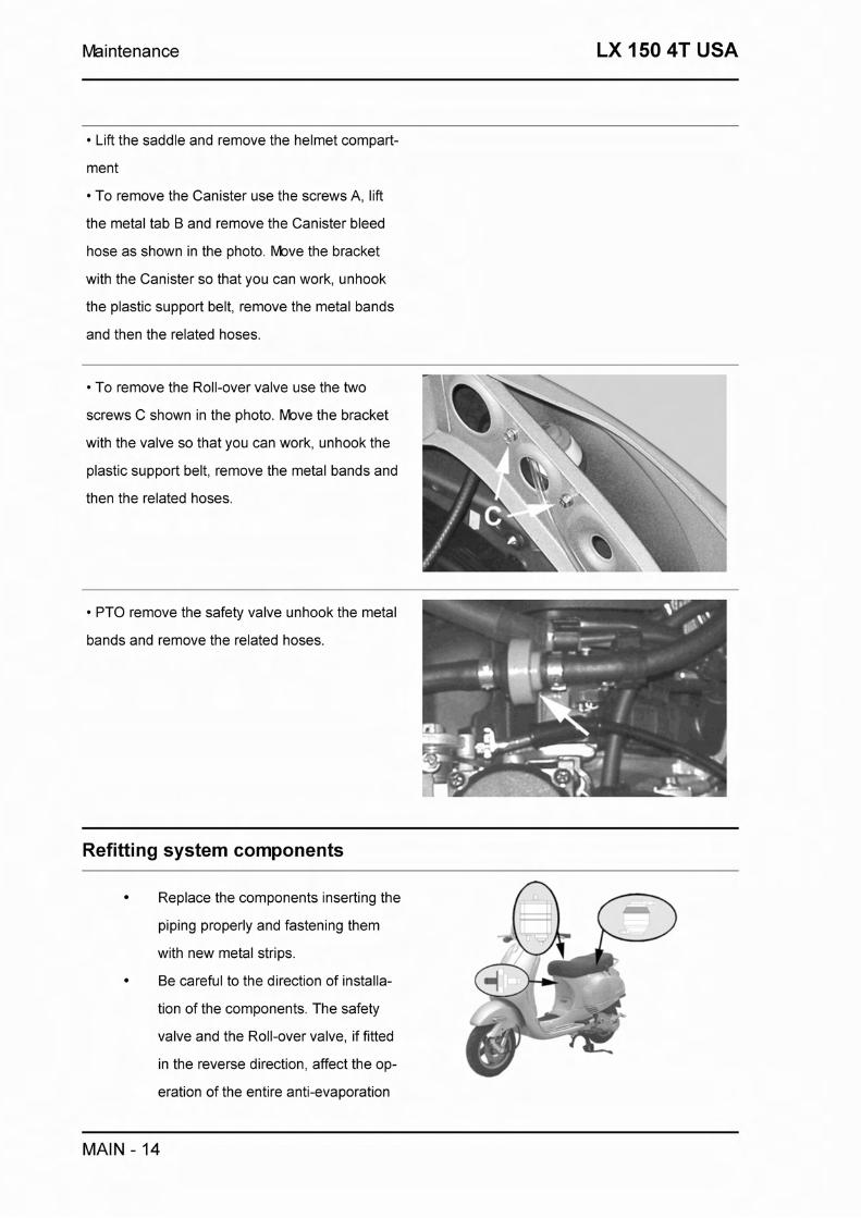
Lift the saddle and remove the helmet compart-
ment
To remove the Canister use the screws A, lift
the metal tab B and remove the Canister bleed
hose as shown in the photo. Move the bracket
with the Canister so that you can work, unhook
the plastic support belt, remove the metal bands
and then the related hoses.
To remove the Roll-over valve use the two
screws C shown in the photo. Move the bracket
with the valve so that you can work, unhook the
plastic support belt, remove the metal bands and
then the related hoses.
Refitting system components
Replace the components inserting the
piping properly and fastening them
with new metal strips.
Be careful to the direction of installa-
tion of the components. The safety
valve and the Roll-over valve, if fitted
in the reverse direction, affect the op- e
eration of the entire anti-evaporation
MAIN - 14

LX 150 4T USA Maintenance
system.
Canister inspection
The Canister is fundamental for treating the hydrocarbons contained inside the volume of gas depart-
ing the fuel tank when the internal pressure rises (due to the heat induced by the radiator, engine or
ambient temperature).
The volume of air is limited by the operation of ventilation valve (Roll-over).
Even though the quantity of hydrocarbons coming from the tank is fairly small, active carbon should
be regenerated by a reversed flow of the ambient air sucked in by the engine, to prevent the satura-
tion of the canister.
This carbon pollution and regeneration phenomena occur during each cycle of utilization of the
vehicle.
The Canister needs to be removed to be inspec- w" ted, keeping the 3 pipes connected.
Shake the Canister and check that
there is no noise. , . I -
Using a compressed air gun, blow al-
ternately into the 3 ducts and check
that no pressure builds up into the
Canister.
Check that the air flow is always free
and that no carbon residues come out
of the piping.
If abnormal noise, clogging or carbon losses are
noticed, replace the Canister.
Safety valve check
The Canister is cleaned by an air flow controlled by the vacuum inlet located on the intake manifold.
To guarantee the correct operation of the engine, the mass air flow must not be excessively large;
this is obtained by using a narrow section (0.9mm) for the inlet on the intake manifold.
The Canister tubing connections comprise the installation of a safety valve.
This is a unidirectional valve that ensures the air flow towards the manifold when the control vacuum
is over 200mbar.
MAIN - 15

Maintenance LX 150 4T USA
The engine vacuum at idle causes a weak air flow that can be easily compensated for with the idle
adjustment parameters.
When the vehicle is stationary, the safety valve will be shut due to the lack of control vacuum; for this
reason, any expansion of the fuel tank will not pollute the intake manifold thus preventing engine
floods.
The valve should preferably be removed from the
vehicle upon inspection; alternatively, it will be
sufficient to access the tubing on the manifold
side.
Connect the MI W A C pump on the engine side
duct. , '. Set the pump control onto "vacuum", then slowly
apply vacuum to check the valve opening
threshold.
If different pressures are found, replace the valve.
N.B. If the opening vacuum is too high, it causes
a lack of active carbon regeneration; on the other
hand, if it is too low, it increases the air flow rate
to the engine, thus causing a poor fuel-oxygen
mixture at idle.
Characteristic
Standard opening vacuum
200 + 260 mbar
Roll-over valve check
The valve should allow the following results:
Tank aeration when running (ambient air enters into the tank based on the volume of fuel used).
Tank pressurization (the tank internal temperature may rise when running or while stopped. The
valve should pressurize the tank so to limit the amount of fuel vapors departing towards the Canis-
ter).
Prevent the liquid fuel pollution of the Canister (if the vehicle falls, the valve should interrupt the con-
nection to the Canister).
The valve must be removed from the vehicle
MAIN - 16

LX 150 4T USA Maintenance
upon inspection.
A MI W A C pump and a length of pipe are
needed for the inspection; proceed as follows:
Attach the M l W A C pump to the lower joint to
the safety valve (white).
Set the pump control onto "vacuum" and, whilst
keeping the valve aligned with its vertical axis,
check that air may be sucked in without observing
any movements on the manometer needle gauge. f r
Set the pump onto "pressure" and, whilst keep-
ing the valve aligned with its vertical axis, check
that the valve can be pressurized to values
slightly below 0.1 bar (-60mbar). 1 N.B. The calibration pressure can be easily re-
cognized as, when reached, the valve will start to
discharge air thus emitting a weak noise.
Align the valve with its horizontal axis and
check that it can be pressurized to values much
higher than the calibration pressure (e.g. 0.5bar
without it necessarily being maintained).
Replace the valve if anomalies are found.
N.B. Any valve failure may cause the fuel tank to
deform or increase of the Canister operating re-
quirements.
MAIN - 17

Maintenance LX 150 4T USA
MAIN - 18


Troubleshooting LX 150 4T USA
Engine
Poor performance
POOR PERFORMANCE
Possible Cause Operation
Air filter clogged or dirty Remove the sponge, wash with water and sham- poo, then impregnate it in a 50% mixture of fuel
and specific oil (Selenia Air Filter Oil), then press it without squeezing, let it drip and replace it
Carburettor jets or fuel cock clogged or dirty Remove, wash in solvent and dry with com- pressed air
Vacuum fuel tap dirty or faulty Check the tap's filter; if necessary drain the fuel and clean the tank. As a last resort, replace the
fuel tap
Automatic choke device (on carburettor) faulty Check the wiring and ensure the pin slides cor- rectly; replace if necessary.
Drive belt excessively worn Check and replace if required.
Low compression: wear of linings, cylinder and valve
Replace worn parts
Engine oil level exceeding the maximum Check the causes and restore the correct level
Excessive scaling in the explosion chamber Remove the scale from cylinder, piston, head and valves
Wrong timing or worn timing components Restore the timing or replace worn parts
Clogged silencer Replace
Inefficient automatic transmission Check the pulley sliding and rollers, replace faulty components, lubricate the mobile driven pulley
guide with grease Montblanc Molybdenum Grease
Valve seat deformed Replace the head unit
Overheated valves Remove the head and the valves, grind or re- place the valves
Defective float valve Check the proper sliding of the float and the valve efficiency
Cylinder worn out 1 piston rings worn or broken Replace the cylinder-piston assembly or the pis- ton rings only
Rear wheel spins at idle
REAR WHEEL TURNING WITH IDLE ENGINE
TROUBL - 2

LX 150 4T USA Troubleshooting
Possible Cause Operation
Idle rpm too high Adjust the engine idle speed and the CO, if re- quired.
Clutch failure Check clutch springs / masses
Starting difficulties
STARTING PROBLEMS
Possible Cause Operation
Battery is down Check the battery charge condition. If the battery shows signs of sulfation, replace it. Before in-
stalling the new battery, charge it for eight hours with a current corresponding to 1/10 of the capa-
city of the battery
Faulty spark plug or incorrect ignition advance Replace the spark plug or check the ignition cir- cuit components
Flooded engine Start up keeping the gas fully open. If the engine won't start, remove the spark plug, dry it and be- fore replacing it, start the engine to eject the ex- cess of fuel, keeping the cap connected to the
spark plug and the latter to earth. If fuel has fin- ished, refuel and start up
Incorrect valve seal or wrong valve adjustment Inspect the head and/or set the correct clearance
Starting rpm too low. Starter motor faulty. Check starting motor
Wrong fuel specifications Drain the fuel and then refuel
Vacuum fuel tap faulty Check fuel outflows correctly from the outlet hose when simulating a vacuum in the vacuum hose.
Automatic choke device (on carburettor) faulty Check the wiring and ensure the pin slides cor- rectly; replace if necessary.
Safety switches faulty Using a tester check for continuity of resistance with the switch engaged, replace if necessary
Carburettor jets clogged or dirty Remove, wash in solvent and dry with com- pressed air
Air filter clogged or dirty Remove the sponge, wash with water and sham- poo, then impregnate it in a 50% mixture of fuel
and specific oil (Selenia Air Filter Oil), then press it without squeezing, let it drip and replace it
Excessive oil consumption/Exhaust smoke
EXCESSIVE OIL CONSUMPTION 1 SMOKE UPON EXHAUST
TROUBL - 3
Troubleshooting LX 150 4T USA
Possible Cause Operation
Worn valve guides Check and replace the head unit if required
Worn valve oil guard Replace the valve oil guard
Oil leaks from the couplings or from the gaskets Check and replace the gaskets or restore the coupling seal
Worn or broken piston rings, or mounted incor- Replace the piston rings or the cylinder unit rectly
Insufficient lubrication pressure
POOR LUBRICATION PRESSURE
Possible Cause Operation
By-Pass remains open. Check the By-Pass and replace if required. Care- fully clean the By-Pass area
Oil pump with excessive clearance Perform the dimensional checks on the oil pump components
Oil filter too dirty Replace the cartridge filter
Oil level too low Restore the level using the recommended oil type (Selenia HI Scooter 4 Tech)
Engine tends to cut-off at full throttle
ENGINE TENDS TO CUT OUT AT FULL THROTTLE
Possible Cause Operation
Main jet obstructed Remove the carburettor, clean with solvent and then dry with compressed air.
Presence of water or condensation in the carbur- Remove the bowl, clean with solvent and then dry ettor float bowl with compressed air.
Low fuel level in float bowl Restore the level inside the float bowl by bending the petrol inlet thrust plate, so to have, with the
carburettor upside-down, the float perfectly flushed with the mating surface of the bowl.
Engine tends to cut-off at idle
ENGINE TENDS TO CUT-OFF AT IDLE
Possible Cause Operation
Idle adjustment is incorrect Adjust with the rpm counter
Wrong timing Adjust the timing and check the timing compon- ents
Starter remains pressed Check: electric connections, circuit continuity,
TROUBL - 4

LX 150 4T USA Troubleshooting
Possible Cause Operation
mechanical sliding, and presence of power; re- place, if required
Faulty spark plug or incorrect ignition advance Replace the spark plug or check the ignition cir- cuit components
Compression end pressure too low Check the seals of the thermal unit and replace worn components
Idle nozzle dirty Wash with solvent and dry with compressed air
High fuel consumption
HIGH CONSUMPTION
Possible Cause Operation
Air filter clogged or dirty Clean
Inefficient starter Check: electric connections, circuit continuity, mechanical sliding, and presence of power
Slackened nozzles Check the maximum and minimum nozzle locking into their seat
Incorrect float level Restore the level in the basin by bending the fuel inlet pin thrusting reed on the float so as to have the float parallel to the basin plane with upturned
carburettor
Transmission and brakes
Clutch grabbing or performing inadequately
SLIPPAGE OR IRREGULAR PERFORMANCE
Possible Cause Operation
Slippage or irregular performance Ensure there is no grease on the rollers. Check the contact surface of the clutch shoes is thicker in the middle and equally distributed on all three
shoes. Check the clutch drum is not scored or ab- normally worn. Never run the engine with the
clutch drum not installed.
Insufficient braking
INEFFICIENT OR NOISY BRAKING
Possible Cause Operation
Bake pads or shoes worn Replace the pads or shoes and check the status of the brake disc or drum
TROUBL - 5

Troubleshooting LX 150 4T USA
Possible Cause Operation
Front brake disc loosen or deformed Check tightening torque of the disc fixing screws; using a dial gauge and with the wheel on the vehicle, measure the disc's axial deviation
Air bubbles in the braking hydraulic system Carefully bleed the hydraulic system (spring ac- tion of the brake lever should not be felt)
Coolant leaking from the hydraulic brake circuit Flexible connections, piston or brake pump gas- kets faulty. Replace
Excessive play on rear brake cable Adjust the play using the adjusting screw located on the top of the crankcase
Brakes overheating
BRAKE OVERHEATING
Possible Cause Operation
Rubber gaskets expanded or sealed Replace the gaskets
Pump compensation holes clogged Clean carefully and blow with compressed air
Brake disc slackened or deformed Check the tightening of the brake disc screws; measure the disc axial deviation using a compar-
ator and keeping the wheel mounted on the vehicle
Defective piston sliding Check the caliper and replace any damaged parts
Electrical system
Battery
BATTERY
Possible Cause Operation
Battery This one component of the system needs check- ing more frequently and servicing more carefully than any other. If the vehicle is to stand idle for
any length of time (one month or longer), the bat- tery will need recharging periodically. The battery discharges completely over a period of around 5 - 6 months. When fitting the battery to the vehicle, take care not to switch the connections: the black earth lead is connected to the negative terminal and the red lead to the positive terminal marked +. To charge the battery, follow the instructions
described in Chapter ELECTRICAL EQUIP- MENT.
TROUBL - 6
LX 150 4T USA Troubleshooting
Turn signal lights malfunction
FLASHING LIGHTS NOT WORKING
Possible Cause Operation
Electronic ignition unit faulty With the key-switch set onto ((ON)), jumper con- tacts 1 (Blue-Black) and 5 (Orange) located on
the main control unit connector. If the turn signal lights do not stay lit when switch is operated, replace the ECU, otherwise check
wiring and switch.
Steering and suspensions
Heavy steering
HARDENING STEERING
Possible Cause Operation
Excessive steering wheel clearance Check the tightening of the top and bottom ring nut. If the anomaly continues during the steering wheel rotation even after the adjustment, check
the bearing ball rolling seats. If they are recessed or if the balls are squashed, replace.
Excessive steering play
STEERING PLAY EXCESSIVE
Possible Cause Operation
Steering play excessive Check the tightening of the upper and lower rings. If steering rotation is still uneven, check the bear- ing ball rolling races. Replace if the races appear
to be embedded or if the balls are flattened
Noisy suspension
NOISY SUSPENSION
Possible Cause Operation
Noisy suspension If the front suspension is noisy, check the front shock absorber, and the condition of the ball
bearings. Finally check the tightening torques for wheel axle nut, and calliper and disc fixing
screws. Inspect the swing-arm connecting the en- gine to the frame and the check the rear shock
absorber.
TROUBL - 7

Troubleshooting LX 150 4T USA
Suspension oil leakage
OIL LEAKING FROM SUSPENSION
Possible Cause Operation
Oil leaking from suspension Replace the shock absorber
TROUBL - 8


Electrical system LX 150 4T USA
Legend
1. Rear brake stop button
2. Highllow beam selector
3. Turn indicator selector
4. Horn button
5. Immobilizer aerial
6. Electronic ignition
7. Relay
8. Horn
9. Turn indicator bulb
10. Front left indicator.
11. Voltage regulator
ELE SYS - 2

LX 150 4T USA Electrical system
12. HV coil
13. Heater
14. Automatic choke
15. Pick-up
16. Magneto
17. Starter motor
18. Fuse holder with 2 15A fuses
19. 2 turn indicator bulbs
20. Rear left indicator
21. Rear parking and brake light bulb
22. Complete taillight
23. License plate light bulb
24. License plate light cover
25. 2 turn indicator bulbs
26. Rear right indicator with bulb
27. Fuel warning light transmitter
28. Starter motor contactor
29. Battery 12V-9"
30. Engine oil pressure sensor
31. Immobilizer diagnostic instrument output
32. Front right indicator
33. Turn indicator bulb
34. Key switch
35. Start button
36. Front brake stop button
37. Fuse holder with 2 7.5 A fuses
38. Anti-theft and diagnostics LED
39. Complete headlight
40. Rear parking light bulb
41. Bulb for highldipped beam light 12V - 355W 160W
42. High beam indicator lamp
43. Engine oil pressure lamp
44. Right indicator lamp
45. Fuel warning lamp
46. Left indicator lamp
ELE SYS - 3

Electrical system LX 150 4T USA
47. Instrument lighting light bulb
48. Lights indicator lamp
49. Odometer with lamps and level indicator instrument
50. Space for acoustic lamp
Wire colour coding
R = Red
B = White
BI = Blue
N = Black
V= Green
Rs = Pink
Mr = Brown
Gr = Grey
Az = Light blue
G = Yellow
Vi = Purple
A = Orange
Conceptual diagrams
Ignition
IGNITION
ELE SYS - 4
LX 150 4T USA Electrical system
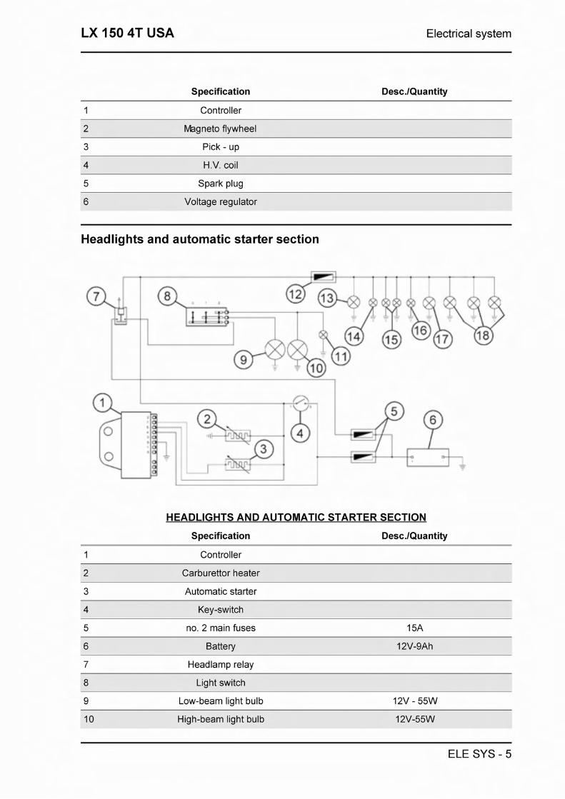
Specification Desc.lQuantity
1 Controller
2 Magneto flywheel
3 Pick - up
4 H.V. coil
5 Spark plug
6 Voltage regulator
Headlights and automatic starter section
. .ILL.! * 7-+ - - 4 C - * ,
HEADLIGHTS AND AUTOMATIC STARTER SECTION
Specification Desc.lQuantity
1 Controller
2 Carburettor heater
3 Automatic starter
4 Key-switch
5 no. 2 main fuses 1 5A
6 Battery 12V-9Ah
7 Headlamp relay
8 Light switch
9 Low-beam light bulb 12V - 55W
10 High-beam light bulb 12V-55W
ELE SYS - 5

Electrical system LX 150 4T USA
Specification Desc.lQuantity
11 High beam indicator lamp 12V - 1.2W
12 Fuse
13 License plate bulb 12V-5W
14 Lights indicator lamp 12V - 1.2W
15 No 2 bulbs for instrument panel lighting 12V - 1.2W
16 No 1 bulb for instrument panel lighting 12V - 2W
17 Taillight bulb 12V-5W
18 No 3 Lamps of front position 12V-5W
Battery recharge and starting
BATTERY CHARGER AND STARTING
Specification DescJQuantity
1 Magneto flywheel
2 Voltage regulator
3 Pick - up
4 Main fusible 15A
5 Battery 1 2V-9Ah
6 Starter relay
7 Starter motor
8 Start up button
ELE SYS - 6

LX 150 4T USA Electrical system
Specification Desc.lQuantity
9 Front and rear brake light button
10 Brake light filament 12V-21 W
11 Fuses 7,5 A
13 Controller
Level indicators and enable signals section
CONSENSES AND LEVEL INDICATORS
Specification Desc.lQuantity
1 Controller
Battery 12V-9Ah
3 Main fusible 1 5A
5 Engine oil pressure sensor
6 Engine oil pressure lamp 12V - 2W
7 Reserve fuel light 12V-1,2W
8 Fuel level gauge
9 Fuel level sender
10 Fuses 7,5 A
11 Immobilizer aerial
ELE SYS - 7

Electrical system LX 150 4T USA
Specification Desc.lQuantity
12 Low engine oil pressure sensor
13 lmmobiliser LED
14 Front and rear brake light button
15 Filament for rear brake light 12V - 21 W
Turn signal lights
TURN INDICATORS AND HORN
Specification Desc.lQuantity
1 Controller
2 Indicators switch
3 4 Turn indicator bulbs 12V-1 OW
4 Turn signal warning light bulbs 12V - 2W
5 Main fusible 15A
6 Battery 1 2V-9Ah
7 Horn
8 Fuses 7,5 A
10 Horn button
11 Space for turn indicator acoustic lamp
ELE SYS - 8

LX 150 4T USA Electrical system
Instruments and warning lights control board
CONNECTOR 4 PIN
Specification
1 Earth
2 Turn signal warning
3 RHS turn signal warning light
Not used
CONNECTOR 5 PIN
Specification
1 Fuel level gauge
2 High-beam warning light 12V - 1,2W
3 Engine oil pressure lamp 12V - 2W
5 Low-fuel warning light
Dashboard illumination and headlamp warn- ing light
CONNECTOR 2 PIN
Specification
1 Anti-theft and diagnostics LED
2 Anti-theft and diagnostics LED
Checks and inspections
lmmobiliser
The electronic ignition system is powered by dir-
ELE SYS - 9

Electrical system LX 150 4T USA
ect current and an anti-theft immobiliser device is "ON"
incorporated into the ecu. The ignition system ----------- LED ACCESO ------------------------. CENTRALINA
consists of: VERGINE LED SPENTO . . . . . . . . . . . . . . . . . . . . . . . . .
- ECU
- immobilizer antenna !0,7" LED ACCESO -------.------..--------------. - master and slave keys with in-built transponder CENTRALINA
PROGRAMMATA - h.t. coil ------------------------------- LED SPENT0
- diagnostic LED
The diagnostic LED also offers a deterring func-
tion. This function is activated whenever the key-
switch is turned onto <<OFF>, in order to avoid
comprising the battery CHARGE; it remains act-
ive for 48 hours.
When the keyswitch is turned onto <<ON>> the de-
terring function is deactivated and is followed by a
single flash to confirm the <<ON> position. the dur-
ation of the flash depends on the program in-
stalled on the ECU (see figure).
In the event that the LED remains off with the I 7 key-switch set onto <<ON>, it is then necessary to
carry out the following procedures:
- check potential difference at battery RC6SO [ ]lF$ BLU
- ensure 15A fuse is in working conditions.
Attach the immobiliser tester to the diagnostic
port (see ET4 125 manual) located behind the
front LHS fuse holder flap.
If the serial LED stays off, proceed by inspecting
the electronic control unit as indicated below:
Detach the connector from the ECU and check
the following:
- Presence of battery potential difference between
terminal 4 (RedIBlue) and earth
- Presence of battery potential difference between
ELE SYS - 10

LX 150 4T USA Electrical system
terminals 4 (RedIBlue) and 8 (black), as shown in
the figure.
ROSS0 BLU
NERO
- Presence of battery potential difference between
terminals 5 and 8 with the key-switch onto KOND.
If no anomalies are found, replace the electronic ARANCIONE
control unit.
Virgin circuit
- 1 - - 2 3 4 - 5 - 6 - 7 -
When the ignition circuit is not coded, the engine
is limited to 2,000 rpm and an evident lack of
power may be noted when accelerating.
To encode the system it is necessary to use the
MASTER (brown) and SLAVE (blue) keys as in-
dicated below:
- Insert the MASTER key, turn the key-switch
onto "ON" and leave it in this position for 2
seconds (limit values: 1 - 3 seconds).
- Alternately insert all available blue keys leaving
each key onto "ON" for 2 seconds.
- Finally reinsert the MASTER key and turn the
key-switch onto "ON" for 2 seconds.
The maximum allowable time available for switch-
ing from one blue key to the next is 10 seconds.
During a single encoding sequence a maximum
of 7 blue keys are allowed.
- - 1 2 7
3 - 4 - - 5 6 7
7
ELE SYS - 11
Ivl + -
[vi
+ . * *
C-

Electrical system LX 150 4T USA
It is strictly necessary to follow the exact se-
quence and timings.
If necessary, repeat the whole procedure from the
beginning
Once the electronic control unit has been suc-
cessfully encoded, this is permanently
linked to the transponder located inside the MAS-
TER key.
With this link established, it is now possible to en-
code new SLAVE keys, in the event of losses, re-
placements, etc. Every encoding sequence su-
persedes the previous one.
In the event that the SERVICE keys should be-
come un-coded, the high tension circuit must be
thoroughly inspected:
Shielded cap resistance: - 5000 n. In any case, it is recommended the use of spark
plugs as shown in the figure.
Diagnostic codes
I
number of possible faults. 4
CCCCS3 rlSSO
This occurs with LED off for 2 seconds, after
which diagnostic codes are transmitted with 0.5 - ............... - .... - -
second flashes. After the failure code signal, the
LED turns on with solid light to indicate that start
up is not possible; see the graph:
2 FLASH CODE
- Example electronic control unit programmed,
transponder absent and/or aerial malfunctioning.
Ignition disabled - Vehicle immobilised
3 FLASH CODE
ACCFW FISSO n - oL , Following the flash (0.7 seconds) which confirms ~E?,~,~:- - . - - .L. --.-.....
ELE SYS - 12
that the system is now onto ccON)), a sequence of LED- - :;-;-*J fi - . , , * - . .-----.-------*--------
coded flashes may be observed, signalling a ,, < ,
1

LX 150 4T USA Electrical system
- Example electronic control unit programmed,
aerial in working condition and transponder code
unknown.
Ignition disabled - Vehicle immobilised
Diagnostic code - 2 flashes
When the 2-flash code is noted, proceed as follows:
-Check whether the anomaly persists using different keys (including the MASTER key). If the prob-
lem is present with any key, detach the antenna connector from the electronic control unit and check
the antenna for electrical continuity using a multimetre. Replace the antenna if necessary.
If no faults are found, replace the ECU.
CAUTION
BEFORE PERFORMING THE STORING PROCEDURE ON THE NEW CONTROL UNIT, CHECK THAT NO MALFUNCTION CODE IS SIGNALLED. THIS PRECAUTION IS NEEDED TO AVOID WASTING A NEW CON- TROL UNIT.
Specific tooling
020331Y Digital multimeter
Electric characteristic
Resistive value
- 7 + 9 O h m
Diagnostic code - 3 flashes
If the 3-flash diagnostic code is displayed, check if the anomaly persists after inserting the MASTER
key into the ignition switch.
- If the malfunction disappears when the MASTER key is used, proceed to code the service (blue)
keys again.
- If the anomaly persists, then the MASTER key and the control unit are not matched. In that case,
replace the control unit and proceed to code the keys.
The immobilizer system is in working order when, after turning the ignition switch to <(ON)), one
0.7-second flash is emitted (see chart).
In that case, ignition is possible.
Example - Electronic control unit programmed,
transponder present, key programmed and aerial
ELE SYS - 13

Electrical system LX 150 4T USA
in working order. lgnition enabled (normal oper-
ating conditions)
lgnition circuit
Every operation involving the detachment of wires (i.e. ignition system and wiring checks) must be
performed when the engine is not running: the ECU may otherwise become damaged beyond re-
pair.
The main power supply is provided by the battery; the system is adjusted so that any battery voltage
loss is immediately picked up by the starter system and is therefore almost irrelevant to the ignition
system.
The Pick-Up is connected to the ECU via a single wire; the latter is therefore connected to the pick-
up through the frame and the earth wire from the engine.
In order to avoid problems with the ignition system during the start-up phase, it is extremely important
that the frame-engine earth connections are in good conditions.
No spark plug
When noticing no spark plug proceded as follows:
- Pick-Up inspection.
Detach the ECU connector and check for continu- I" I ity between terminals 2 (Green) and 8 (Black). 1 I
r
I
The inspection must include the pick-up and it's _ - power cable. 1 2 3 4 1 5 617 P,
If an open circuit is found, repeat the inspection %WE - urn7 --.--
between the flywheel connector and earth. If un-
acceptable values are found, proceed by repla-
cing the pick-up, otherwise repair the cable.
Electric characteristic
Resistance value pick-up
Resistance value pick-up: 105 + 124 ohm
ELE SYS - 14

LX 150 4T USA Electrical system
- H.T. coil primary circuit inspection
Detach the connector from the ECU and check for
continuity between terminals 3 (purple) and 8
(black) (see figure).
If unacceptable values are found, repeat the in-
spection directly from the positive and negative
terminals of the H.T. coil primary circuit.
If the values are within the prescribed limit, pro-
ceed by repairing the wiring or reattaching all wir-
ings, otherwise replace the H.T. coil.
Dl . 112131415161718
VIOLA
Electric characteristic
Resistance value H.V. coil primary check
Resistance value H.V. coil primary check: 0,4 +
0,5 ohm
- H.T. coil secondary circuit inspection
Detach the spark plug cap from the H.T. cable and measure the resistance between the H.T. cable
terminals and the negative wire of H.T. coil (see figure).
If unacceptable values are found, replace the H.T. coil. For a more thorough analysis, it is possible to
proceed by checking the peak tension using the adapter for the multimetre.
Specific tooling
020409Y Multimeter adapter (Peak voltage measurement)
Electric characteristic
Resistance value H.V. coil secondary check
Resistance value H.V. coil secondary check: - 3000 & 300 ohm
- Pick-Up
Detach the ECU connector and connect the posit-
ELE SYS - 15

Electrical system LX 150 4T USA
ive terminal to connector no. 2 and the negative 11 12131415161718 terminal to connector no. 8 (see figure).
Crank the engine using the starter motor and
check the tension produced by the pick-up. El
If unacceptable values are found, replace the
Pick-Up. ,
N.B.
THE MULTIMETER MUST BE SET TO MEASURE DIRECT VOLTAGE.
Electric characteristic
Voltage value pick-up
Voltage value pick-up: > 2 Volt
- H.T. coil
With ECU and H.T. coil connected to the circuit,
measure the coil primary circuit tension during the
start-up test, using the peak tension adapter and
earthing the positive terminal and connecting the
positive terminal to the coil. ...
If unacceptable values are found, replace the
ECU.
CAUTION
THE NEGATIVE TERMINAL OF THE PRIMARY COIL CIRCUIT IS BLACK.
Electric characteristic
Voltage value H.V. coil
Voltage value H.V. coil: > 100 Volt
Battery recharge circuit
The charging circuit consists of tri-phase generator and a flywheel magneto.
The generator is connected to the voltage regulator.
This is then connected to the positive pole of the battery (via the 15A fuse) and earth.
This system does not therefore feature any connection to the key-switch.
The tri-phase generator allows for remarkable recharging power and allows to reach a good com-
promise between output power and stability at idle.
ELE SYS - 16

LX 150 4T USA Electrical system
For this reason is necessary that the idle is adjusted as prescribed.
Specific tooling
020333Y Single battery charger
020334Y Multiple battery charger
Stator check
Disconnect the connector from the voltage regu- I lator and check the presence of continuity I between each yellow wire with the other two.
Electric characteristic
Stator check I
Ohm value: 0,7 + 0,9 Ohm
Also check that each yellow wire is insulated from
earth.
If non-conforming values are detected, repeat the
checks directly on the stator; in case of further
wrong values, replace the stator or fix the wiring.
Voltage regulator check
ELE SYS - 17

Electrical system LX 150 4T USA
With battery fully charged and lights off, measure pT-1 the voltage at the battery poles with engine at
t 1 . - L high speed.
Voltage should not exceed 15.2 Volt.
In case of higher voltage, replace the regulator. F-7 If voltage is less than 14 Volt, check the stator I and its wiring. I
Recharge system voltage check
Connect the induction collet of an amperometer to
the positive cable of the voltage regulator, meas-
ure the battery voltage and turn off the lights of
the vehicle with engine off, then wait until voltage
settles at about 12 Volt. Start the engine and
measure the current delivered by the system with
lights on and engine at high speed.
If the delivered current value is less than 8A, re-
peat the test using a new regulator andlor stator.
Choke Inspection
For the resistive and functional inspection of the
component see the engine section. To check the
power supply, leave the connector attached to the
circuit and check there is battery tension between
the two terminals with engine running (see figure).
If no tension is measured at all, connect the neg-
ative terminal of the multimetre to earth, and the
positive terminal to the orange wire from the auto-
matic choke device; with the key-switch onto
((ON> check for battery potential; if this is not
ELE SYS - 18

LX 150 4T USA Electrical system
found, check wiring and key-switch.
- If battery potential is found, repeat the inspection
, from the connector to the ECU. -=. - .\?, ".." .....- '."'".. a *.-
i. --
After detaching the choke device, start the engine -- - ' ' - 1
- and, while at idle, check for tension connecting -.-
_I + I - '3' the positive terminal of the multimetre to terminal - -
5 (Orange) and the negative to terminal 7 - - ", . *. - (WhiteIBlack) (see figure).
If no tension is found, replace the ECU; otherwise
check the wiring between the choke device and
the ECU.
Turn signals system check
- If the turn signal lights are faulty, proceed as fol- P-l lows:
- Detach the ECU connector and check for battery
tension between terminal 5 (Orange) and earth,
with the key-switch onto <<ON)>.
- Check the same is present between terminals 5
(Orange) and 8 (Black).
AFANCION E ( &
If no tension is measured, check the wiring, other-
wise proceed as follows: n - Jumper terminals 1 (BlacklBlue) and 5 (Orange), I I see figure, and alternately operate the turn signal
switch towards left and right wit the key-switch N E RO-BLU
onto <<ON)) and check the bulbs go off.
If this happens, replace the ECU, as faulty.
If this does not happen, check the wiring between
AFANCION E I the ECU and the turn signal switch, hence repeat
the test.
ELE SYS - 19

Electrical system LX 150 4T USA
Sealed battery
If the vehicle is provided with an airtight battery, the only maintenance required is the check of its
charge and recharging, if needed.
These operations should be carried out before delivering the vehicle, and on a six-month basis for
storage with open circuit.
Besides upon pre-delivery it is therefore necessary to check the battery charge and recharge it, if re-
quired, before storing the vehicle and afterwards every six months.
INSTRUCTIONS FOR THE RENEWAL RECHARGE AFTER OPEN-CIRCUIT STORAGE
1) Voltage check Before installing the battery on the vehicle, perform an open-circuit voltage check
using a conventional tester.
- If voltage exceeds 12.60 V, the battery may be installed without any renewal recharge.
- If voltage is below 12.60 V, a renewal recharge is required as explained at 2).
2) Constant-voltage battery instructions
- Constant voltage charge equal to 14.40 - 14.70V
- Initial charge current equal to 0.3 - 0.5 x rated capacity
- Charge time:
Recommended 10 - 12 h
Minimum 6 h
Maximum 24 h
3) Constant-current battery instructions
- Charge current equal to 1/10 of the battery rated capacity
- Charge time: 5 h
Dry-charge battery WARNING
BATTERY ELECTROLYTE IS POISONOUS AND CAN CAUSE SERIOUS BURNS AS IT CON- TAINS SULPHURIC ACID. AVOID CONTACT WlTH THE EYES, THE SKlN AND GARMENTS. IN CASE OF CONTACT WlTH THE EYES OR SKlN RINSE ABUNDANTLY WlTH WATER FOR ABOUT 15 MINUTES AND SEEK IMMEDIATE MEDICAL ASSISTANCE. IF THE LIQUID IS INGESTED IMMEDIATELY DRINK LARGE QUANTITIES OF WATER OR MILK. SUBSEQUENTLY DRINK MILK OF MAGNESIA, BEATEN EGG OR VEGETABLE OIL. CALL A DOCTOR WITHOUT DELAY. BATTERIES PRODUCE EXPLOSIVE GASES. KEEP AWAY OPEN FLAMES, SPARKS AND CI- GARETTES. WHEN A BATTERY IS CHARGED IN CLOSED PLACES ENSURE ADEQUATE VENTILATION. ALWAYS PROTECT THE EYES WHEN WORKING IN THE PROXIMITY OF BATTERIES. POSI- TION THE TUBE BETWEEN THE MUDGUARD AND THE FILTER. KEEP OUT OF REACH OF CHILDREN.
ELE SYS - 20

LX 150 4T USA Electrical system
Installing dry batteries:
1) - Remove the cap from the bleeder and then
carefully pour sulphuric acid into each element.
Note: the acid must have a density 1,260 kg.m-3,
equivalent to 30" Be at a minimum temperature of
15°C until the upper level is reached.
2) - Let the battery rest at least 2 hours, and then
restore the level by pouring additional sulphuric
acid as required.
3) - Recharge the battery within 24 hours using
the recommended battery charger (single) or
(multiple) at an intensity of about 111 0 of the bat-
tery's nominal capacity and until the acid density
is about 1,270 kg.m-3, corresponding to 31" Be
and such values become steady.
4) -After charging, level the acid (adding distilled
water). Close and clean carefully.
5) - After performing the above operations, install
the battery on the vehicle following the steps
((described in Battery recharge>> section of this
manual.
1 Maintain the tube vertical
2 Check the electrolyte level
3 The floater must be free
WARNING
AFTER INSTALLING THE BATTERY AND IN ORDER TO PROVIDE A VENT FOR THE GASES FORMING INSIDE IT, REPLACE THE SHORT CLOSED TUBE NEXT TO THE POSITIVE (+) TERMINAL WITH THE CORRESPONDING LONG OPEN TUBE WHICH IS PRESENT ON THE VEHICLE. CHECK THAT THE TUBE SLOTS ARE TURNED TO THE BATTERY SIDE
Specific tooling
020333Y Single battery charger
020334Y Multiple battery charger
ELE SYS - 21
Electrical system LX 150 4T USA
Battery maintenance
This is the component which requires the most diligent maintenance and frequent inspection. The
main maintenance rules are:
1) Checking the electrolyte level
The electrolyte level must be checked frequently and must reach the upper mark. If the level is too
low, it can be restored only by using distilled water. If water toppings are required too often, check the
vehicle electrical system as this inconvenient is usually a symptom that the battery is working over-
charged and is subject to quick wear.
2) Checking the battery charge level
After restoring the electrolyte level, check its density by using the density gauge. When the battery is
charged, density should be equal to 30-32 Be, corresponding to a specific weight of 12.4-12.6
kN.m-3 at a minimum temperature of 15" C. If density is below 20 Be, the battery is fully discharged
and it is therefore necessary to recharge it.
If the vehicle is not used for a certain period (1 month or more), the battery must be periodically re-
charged.
Within a period of inactivity of approximately tree months, at standard atmospheric conditions, the
battery should be completely discharged. When reinstalling the battery on the vehicle, pay attention
not to invert the connections, considering that the ground wire (black and marked with a (-) sign)
must be connected to the negative terminal, whereas the two red wires, marked as (+), must be con-
nected to the positive terminal.
3) Recharging the battery
Remove the battery from the vehicle detaching the negative wire first. The battery must be charged
using the special battery charger (single or multiple), selecting the relevant battery type on the instru-
ment. Connect the positive cable to the positive pole and the negative cable to the negative pole.
4) Cleaning the battery
Keep the battery always clean, especially the top; coat the terminals with Vaseline.
WARNING
BEFORE CHARGING THE BATTERY, REMOVE THE CAP FROM EACH CELL. KEEP FLAMES AND SPARKS AWAY FROM THE BATTERY WHEN CHARGING.
CAUTION
NEVER USE FUSES HAVING A CAPACITY GREATER THAN THE RECOMMENDED VALUE. THE USE OF A FUSE OF UNSUITABLE CAPACITY MAY RESULT IN SERIOUS DAMAGES TO THE WHOLE VEHICLE OR EVEN CULMINATE IN A FIRE.
CAUTION
DRINKING WATER CONTAINS MINERAL SALTS THAT CAN BE EXTREMLY HARMFUL TO THE BAT- TERY: ONLY USE DISTILLED WATER.
ELE SYS - 22

LX 150 4T USA Electrical system
CAUTION
TO ENSURE MAXIMUM PERFORMANCE THE BATTERY MUST BE CHARGED BEFORE USING THE VEHICLE. INSUFFICIENT BATTERY CHARGE OR LOW ELECTROLYTE LEVEL WHEN FIRST USED WILL RESULT IN PREMATURE FAILURE OF THE BATTERY.
Specific tooling
020333Y Single battery charger
020334Y Multiple battery charger
ELE SYS - 23

Electrical system LX 150 4T USA
ELE SYS - 24


Engine from vehicle LX 150 4T USA
Exhaust assy. Removal - - ----- I
- Remove the two nuts securing the manifold to M
the head
- Unscrew the two screws securing the silencer to
the crankcase then remove the complete muffler
paying attention to the interference between its
support bracket and the cooling casing.
Removal of the engine from the vehicle Removing the engine from the frame
- Remove the left and right panels
- Remove the helmet compartment
- Remove the entire muffler
- Remove the 3 rear brake transmission set
screws shown in the photo
- Disconnect the rear brake transmission by un-
screwing the register screw
- Disconnect the belt cooling hose and the spring
supporting the cocker arm indicated in the photo
- Disconnect the spark plug terminal
ENG VE - 2

LX 150 4T USA Engine from vehicle
- Remove the gas control cable from the carburet-
tor as shown in the photo
- Remove the fuel intake tube from the carburettor
1
Remove the fuel tap and canister safety valve va-
cuum hoses from the manifold as shown in the
figure
- Remove the magneto cable connector, the earth
cable and started motor positive cable as shown
in the figure
ENG VE - 3

Engine from vehicle LX 150 4T USA
- Remove the protection sheathing as shown in
the figure and disconnect the automatic starter , .. and carburettor heater connections
i- -
- Unscrew the engine - rocker arm pin nut from
the right side of the vehicle and remove the pin
from the left side
- Support the vehicle in an adequate manner (e.g.
with the jack) then remove the lower shock ab-
sorber mounting. Now the engine is released.
ENG VE - 4

Engine LX 150 4T USA
This section describes the operations to be carried out on the engine and the tools required
Automatic transmission
Transmission cover
- To remove the transmission cover it is neces-
sary to remove the plastic cover first, by inserting
a screwdriver in the slotted holes. Using the
clutch drum lock wrench shown in the figure, re-
move the driven pulley axle locking nut and wash-
er.
- Remove the engine oil dipstick. . .
- Remove the 10 fixing screws and the ground
cable.
- Remove the transmission cover. If this operation
is carried out directly onto the vehicle, it is neces-
sary to remove the cooling air manifold and the
air-box fasteners.
Specific tooling
020423Y driven pulley stop key
Kic kstart
- Check for any wear on the tooth sector, the
tooth sector shaft, the bushing in the cover, pinion
shaft, its seat in the crankcase and the spring.
- Replace the damaged parts.
- Grease the spring with recommended grease.
- Reassemble the tooth sector loading the spring
with the specific tool.
- Reassemble the washer, circlip ring and kick-
start lever.
Specific tooling
020432Y Starting spring assembly tool
ENG - 2

LX 150 4T USA Engine
Recommended products
JOTA 3 FS Speedometer transmission
Lithium soap grease NLGl 33
- Using the start lever load the spring and put the
pinion in its seat.
- Reassemble the suction opening with the 3
screws and Kickstart cover with the 4 screws. -
Tighten the screws to the prescribed torque.
Remove the starter pinion by pressing the start
lever.
- Unscrew the kickstart screw and remove the
lever.
- Remove the circlip and the washer indicated in
the figure.
- Remove the tooth sector.
WARNING
THE SECTOR KEEPS THE SPRING LOADED, BE CAREFUL TO PREVENT ACCIDENTS
Air duct
- Loosen the Torx screws fixing the air duct panel.
- Remove the 3 screws, hence remove the con-
veyor and the filter.
ENG - 3

Engine LX 150 4T USA
Removing the driven pulley shaft bearing
- Remove the circlip from the inside of the cover.
- Use the Bearing Extractor with the appropriate
adapter to remove the bearing from the crank-
case.
CAUTION
USE AN APPROPRIATE REST SURFACE TO AVOID DAMAGING THE COVER PAINT.
Specific tooling
020376Y Handle for punches
020375Y Adapter 28 x 30 mm
Refitting the driven pulley shaft bearing
- Heat up the internal side of the crankcase using
a heat gun.
- Insert the bearing in its housing and refit the split
ring.
N.B.
ALWAYS REPLACE THE BEARING WITH A NEW ONE UPON REASSEMBLY.
ENG - 4

LX 150 4T USA Engine
Specific tooling
020151Y Air heater "METABO HG 150012"
020376Y Handle for punches
020357Y 32 x 35 mm adaptor
020412Y 15 mm guide
Removing the driven pulley
Remove the spacer, the clutch bell and the entire
driven pulley assembly.
N.B.
THE ASSEMBLY MAY ALSO BE REMOVED WITH THE DRIVING PULLEY ON.
Inspecting the clutch drum
- Check that the clutch bell is not worn or dam-
aged. -
- Measure the clutch bell inside diameter.
Characteristic
Max value clutch bell
Max value: 0 134.5 mm
Standard value clutch bell
Standard value: 0 134.2 mm
Checking the bell working surface eccentricity
- Install the bell on a driven pulley shaft using 2
bearings (inside diameter 15 and 17 mm).
- Lock using the original spacer and nut.
- Place the belllshaft assembly on the support to
check the driving shaft alignment.
ENG - 5

Engine LX 150 4T USA
- Using a feeler pin comparator and the magnetic
base, measure the bell eccentricity.
- Repeat the measure in 3 positions (Central, in-
ternal, external).
- In case of anomalies, replace the bell.
Specific tooling
020074Y Crankshaft aligning tool
020335Y Magnetic stand and comparator
Removing the clutch
- Insert the driven pulley assembly in the special
tool so that the pins engage into the clutch shoes
support holes, hence force the resting screw to its
position.
- Using the special spanner, on the 46mm side,
remove the central clutch lock-nut.
ENG - 6

LX 150 4T USA Engine
- Dismantle the driven pulley components (clutch with fan and return spring with its plastic holder)
CAUTION
THE TOOL MUST BE FIXED IN A VICE AND THE CENTRAL SCREW MUST NOT BE TIGHTEN EXCESS- IVELY, AS THIS MAY DAMAGE THE PULLEY OR THE SPECIAL TOOL.
Specific tooling
020444Y Driven half pulley spring compressor tool
020444Y009 wrench 46 x 55
Inspecting the clutch
- Check the thickness of the clutch mass friction
material.
- The masses must exhibit no traces of lubricants;
in that case, check the driven pulley unit seals.
N.B.
UPON RUNNING-IN, THE MASSES MUST EX- HIBIT A CENTRAL CONTACT SURFACE AND MUST NOT BE DIFFERENT FROM ONE AN- OTHER. DIFFERENT CONDITIONS MAY CAUSE THE CLUTCH TEARING.
CAUTION
DO NOT OPEN THE MASSES USING TOOLS TO PREVENT A VARIATION IN THE RETURN SPRING LOAD.
Characteristic
Check. Minimum thickness
ENG - 7
Engine LX 150 4T USA
Pin retaining collar
- Remove the collar with the aid of two screw-
drivers.
- Remove the three guide pins and the movable
half pulley.
Removing the driven half-pulley bearing
- Remove the retaining ring using two screw-
drivers and a flat blade.
- Using a hammer and a puncher, remove the ball
bearing as shown in the figure.
- Remove the roller bearing using the extractor. 7
N.B. I - - IN ORDER TO AVOID DAMAGING THE THREADED [-;- -- . . *,.I I
BUSHING ON THE DRIVEN PULLEY, REST THE PULLEY ONTO A WOODEN SURFACE.
Specific tooling
020375Y Adapter 28 x 30 mm
020376Y Handle for punches
020439Y 17 mm guide
Inspecting the driven fixed half-pulley
- Measure the external diameter of the pulley's
central bush.
Characteristic
Minimum admissible diameter
0 40.96 mm
ENG - 8
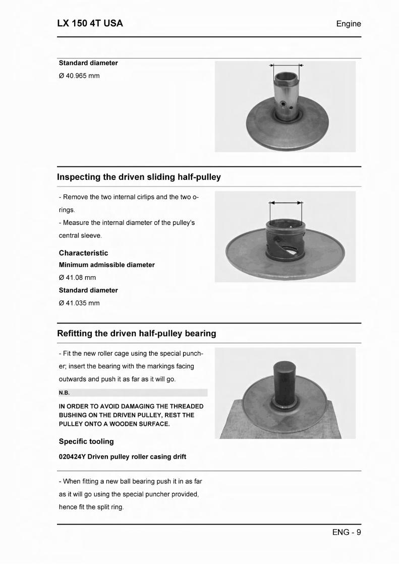
LX 150 4T USA Engine
Standard diameter
0 40.965 mm
Inspecting the driven sliding half-pulley
- Remove the two internal cirlips and the two o-
rings.
- Measure the internal diameter of the pulley's
central sleeve.
Characteristic
Minimum admissible diameter
Standard diameter
Refitting the driven half-pulley bearing
- Fit the new roller cage using the special punch-
er; insert the bearing with the markings facing
outwards and push it as far as it will go.
N.B.
IN ORDER TO AVOID DAMAGING THE THREADED BUSHING ON THE DRIVEN PULLEY, REST THE PULLEY ONTO A WOODEN SURFACE.
Specific tooling \
020424Y Driven pulley roller casing drift
-When fitting a new ball bearing push it in as far
as it will go using the special puncher provided,
hence fit the split ring.
ENG - 9

Engine LX 150 4T USA
Specific tooling
020375Y Adapter 28 x 30 mm
020376Y Handle for punches
020439Y 17 mm guide
Refitting the driven pulley
- Ensure the contact surfaces of the 2 half-pulleys
are not worn, scored or greasy.
- Insert new oil seals and O-rings on the moving
half-pulley.
- Fit the half-pulley onto the bushing using the
protective sheath.
- Before refitting, check the pins and collar are not N 6gr.
worn
- Using a curved-spout grease dispenser, lubric-
ate the driven pulley assembly with approximately
7 g of TUTELA MRM2 grease. Apply the grease
to one of the holes in the bushing until it comes
out through the hole on the opposite side. This
operation is necessary to avoid the presence of
grease beyond the O-rings.
Specific tooling
020263Y Protective sheath
Recommended products
TUTELA MRM 2 Grease for the phonic wheel turning ring
Molybdenum disulphide grease and lithium soap
Inspecting the clutch spring
ENG - 10

LX 150 4T USA Engine
- Measure the length of the spring, while it is re-
laxed.
Characteristic
Standard length
106 mm
Refitting the clutch
- Measure the thickness of the friction material on t the clutch weights. 4 - The clutch weights should bear no traces of lub-
ricants. If they do, check the driven pulley as-
sembly.
N.B.
DURING THE RUNNING-IN PERIOD, THE CLUTCH WEIGHTS MUST HAVE A CENTRAL CONTACT SURFACE AND MUST NOT DIFFER FROM ONE AN- OTHER, OTHERWISE THE CLUTCH MAY GRAP.
CAUTION
DO NOT USE ANY TOOLS TO OPEN THE WEIGHTS AS THIS MAY CHANGE THE LOAD OF THE RE- TURN SPRINGS.
Characteristic
Minimum allowable thickness:
- Support the driven pulley spring compressor
specific tool with the control screw in vertical axis.
-Arrange the tool with the medium length pins
screwed in position KC)) on the inside.
- Introduce the adapter ring no 11 with the cham-
fering facing upwards.
- Insert the clutch on the adapter ring.
- Lubricate the end of the spring that abuts
ENG - 11

Engine LX 150 4T USA
against the servo-system closing collar.
- Insert the spring with relevant plastic support in
contact with the clutch.
- lnsert the driving belt into the pulley unit accord-
ing to their direction of rotation.
- lnsert the pulley unit with the belt into the tool.
- Slightly pre-load the spring.
- Make sure that the clutch is perfectly inserted in-
to the adapter ring before proceeding to tighten
the clutch nut.
- Place the tool into the vice with the control
screw in horizontal axis.
- Fully pre-load the spring.
-Apply the clutch fixing nut and tighten it at the
prescribed torque using the specific wrench
46x55.
- Loosen the tool clamp and insert the belt ac-
cording to its direction of rotation.
- Lock the driven pulley again using the specific
tool.
- Pre-load the clutch contrast spring by turning
and pulling at the same time and place the belt in
the minimum rolling diameter position.
- Remove the driven pulley /belt assembly from
the tool.
N.B.
DURING THE SPRING PRE-LOADING STEP, BE CAREFUL NOT TO DAMAGE THE SPRING PLASTIC ABUTMENT AND THE BUSHING THREADING.
N.B.
FOR DESIGN REASONS, THE NUT IS SLIGHTLY ASYMMETRIC; THE SURFACE SHOULD BE MOUN- TED IN CONTACT WITH THE CLUTCH.
Specific tooling
020444Y Driven half pulley spring compressor tool
ENG - 12

LX 150 4T USA Engine
020444Y011 Adapter ring
020444Y009 wrench 46 x 55
Locking torques (N*m)
Nut locking clutch assembly on pulley 55 + 60 Nm
Refitting the driven pulley
spacer. - Re-fit the clutch drum and the
During the wear check to be performed according
to the scheduled maintenance in the 6,000 Km in-
spection, in the 18,000 Km inspection, etc., it is
advisable to check that the tooth groove bottom is
free from deformations and cracks (see figure). In
case of cracks, the belt must be replaced. ((A)):
The tooth groove bottom must be free from de-
formations and cracks; if not, replace the belt.
- Check that the driving belt is not damaged.
- Check the belt width.
BET DIMENSIONS
ENG - 13

Engine LX 150 4T USA
Specification Desc.lQuantity
Minimum width 21.5 mm
Standard width 22.5 k 0.2 mm
Removing the driving pulley
- Loosen the drive pulley retaining nut, whilst
holding the drive pulley fast with the appropriate
special tool shown in the diagram.
- Remove the drive pulley nut, the dished washer,
the starter motor ratchet plate and the two wash-
ers.
- Remove the fixed half-pulley and the steel
washer.
Specific tooling
020368Y driving pulley stop wrench
- Remove the belt and extract the mobile half-
pulley with the relevant bushing, being careful to
the exit of the rollers freely mounted onto it.
- Remove the roller contrast plate with the relev-
ant guide sliding blocks.
Inspecting the rollers case
- Ensure the internal bearing is not abnormally worn and measure the internal diameter
N.B.
DO NOT CLEAN OR LUBRICATE THE BRONZE BUSH.
ROLLER CAGE BEARING
Specification DescJQuantity
Maximum allowable diameter 0 26,121 mm
Standard diameter 0 26+0 +0,021 mm
PULLEY SLIDING BUSHING
ENG - 14

LX 150 4T USA Engine
Specification Desc.lQuantity
Minimum admissible diameter 0 25,950 mm
Standard diameter 0 26-0,020 -0,041 mm
VARIATOR ROLLER
Specification Desc.lQuantity
Minimum admissible diameter 0 18.5 mm
Standard diameter 0 26&0,1 mm
t-l
- Check the guide shoes for the variator back-
plate are not worn.
- Check there is no wear on the roller ramps, in-
side the roller housing, and the pulley surfaces in
contact with the drive belt, front and back.
Refitting the driving pulley
- Re-fit the fat innermost spacer, the fixed pulley-
half, the outer spacer, the starter motor ratchet
plate, the washer and the nut. Apply recommen-
ded product and tighten the nut to the specified
tightening torque.
- Hold the drive pulley fast with the Compass
Spanner, whilst tightening the nut on the end of
the crankshaft.
N.B.
REPLACE THE NUT WITH A NEW ONE EVERY
ENG - 15

Engine LX 150 4T USA
TIME THE PARTS ARE REASSEMBLED
Specific tooling
020368Y driving pulley stop wrench
Recommended products
Loctite 243 Thread-Brake
Medium Loctite Thread-Brake 243
Locking torques (N*m)
Tightening torque 75 + 83
Refitting the transmission cover
- Check the presence of the 2 centring dowels
and the correct installation of the sealing gasket
for the oil sump on the transmission cover.
- Replace the cover tightening the 10 screws at
the prescribed torque.
- Replace the oil loading caplbar.
- Replace the steel washer and the driven pulley
nut.
- Tighten the nut at the prescribed torque using
the lock wrench and the dynamometric wrench
tools.
- Replace the plastic cover.
Specific tooling
020423Y driven pulley stop key
Locking torques (N*m)
Cover screws I 1 + 13 Driven pulley axis (") 54 + 60
End gear
Removing the hub cover
- Drain the rear hub oil through the draining hole
ENG - 16

LX 150 4T USA Engine
located in the lower part of the hub cover.
- Refit the brake shoes and their springs.
- Remove the 7 fixing screws shown in the figure.
- Remove the rubber cap and the rear brake shoe
drive lever by loosening the fixing screw to reach
the rear fastener.
- Remove the hub cover and all gaskets.
Removing the wheel axle
Removing the hub bearings
- Inspect the bearings and replace any demon-
strating abnormal wear, play or noisiness, follow-
ing the steps below.
- Use the bearing extractor, available as a special
tool, to remove the three gearbox bearings; two in
the crankcase and one in the gearbox cover.
Specific tooling
001467Y009 Bell for bearings external 0 50 mm
001467Y013 15-mm pliers
Removing the wheel axle bearings
- Take out the circlip on the outside of the gear-
ENG - 17

Engine LX 150 4T USA
box cover.
- Remove the bearing using the appropriate spe-
cial tool, taking care to provide a suitable means
of support for the gearbox cover, as shown in the
diagram.
Specific tooling
020376Y Handle for punches
020364Y 25 mm guide
Means of the tools remove to the detent oil like in
the figure.
Specific tooling
020376Y Handle for punches
020359Y 42 x 47 mm hub bearing fitting ad- aptor
Removing the driven pulley shaft bearing
- In order to remove the driven pulley shaft, together with its bearing and oil seal, first remove the
transmission cover and the clutch assembly as previously described.
- Extract the driven pulley shaft from its bearing.
- Remove the oil seal, working from the inside of the bearing.
- Remove the circlip, as shown in the diagram.
Remove the driven pulley shaft bearing using the
appropriate special tool.
Specific tooling
020376Y Handle for punches
020375Y Adapter 28 x 30 mm
020363Y 20mm guide
See also
Removing the driven pulley
ENG - 18

LX 150 4T USA Engine
lnspecting the hub shaft
- Check that the three shafts exhibit no wear or
deformation on the toothed surfaces, at the bear-
ing connections and at the oil guards.
- In case of anomalies, replace the damaged
components.
lnspecting the hub cover
- Check that there are no signs of blemishes or deformation on the mating surfaces.
- Check there is adequate free-play in the bearings and the brake acuating Pin.
- If any of the above anomalies are observed, replace the gearbox cover with a new one.
Refitting the driven pulley shaft bearing
- Heat the bearing housing with a heat gun
Specific tooling
020150Y Support for air heater "METABO HG 150012"
020151Y Air heater "METABO HG 150012"
- Fit the driven pulley shaft bearing, with the bearings visible from the inside of the gearbox cover, us-
ing the appropriate special tool.
Specific tooling
020376Y Handle for punches
- Re-fit the circlip with the opening facing away
from the bearing and fit a new oil seal flush with / the crankcase surface.
ENG - 19

Engine LX 150 4T USA
Refitting the wheel axle bearing
- Heat the bearing housing with the heat gun.
Specific tooling
020151Y Air heater "METABO HG 150012"
020150Y Support for air heater "METABO HG 150012"
- Fit the wheel axle bearing into the gearbox cover using the appropriate special tool
Specific tooling
020364Y 25 mm guide
020360Y 52 x 55 mm adaptor
020376Y Handle for punches
- Fit the circlip.
- Fit the oil seal using the appropriate special tool,
with the sealing lip towards the inside of the gear-
box cover.
Specific tooling
020376Y Handle for punches
020360Y 52 x 55 mm adaptor
Refitting the hub cover bearings
- Heat the bearing housings with a heat gun, available as a special tool.
Specific tooling
020150Y Support for air heater "METABO HG 150012"
020151Y Air heater "METABO HG 150012"
- Fit the three 15 mm bearings using the appropri-
ate special tool.
ENG - 20

LX 150 4T USA Engine
Refitting the hub bearings
- Insert the cover on the crankcase minding the
insertion of the pulley shaft gearing onto the inter-
mediate gear.
Refitting the ub cover
- Fit a new seal together with the centring grub
screws.
- Fit the cover making sure to check the correct
positioning of the bleed hose.
- Tighten the 7 screws to the prescribed torque,
positioning the hose support plate in the position
indicated in the figure.
Locking torques (N*m)
Tightening torque 24 + 27
Flywheel cover
Cooling hood
- Remove the four screw fasteners shown in the
ENG - 21

Engine LX 150 4T USA
diagram and remove the fan cover.
CAUTION
DURING THE REMOVAL PULL THE CONNECTOR OUT OF THE HOUSING IN THE COVER.
- Loosen the clamp and remove the carburettor
from the manifold.
- Remove the manifold assembly after loosening
the two fastenings shown in the figure.
- Remove the two self-tapping screws, left and
right, and the side screw fixing the hoods to the
crankcase base.
- Remove the two hoods.
- Remove the gasket ensuring the seal of the
hoods on the cylinder head.
N.B.
IF THE FLYWHEEL COVER HAS NOT YET BEEN REMOVED, IT IS ALSO NECESSARY TO REMOVE THE TWO KNOB SCREWS ON THE COVER.
If loss of power is noticed at full throttle, on vehicles equipped with these engines, it is suggested to
ream the vacuum port hole located on the intake manifold so to bring its diameter from 0.4 to 1.5 mm.
It must be stressed that this operation must be carried out with the manifold detached from the
vehicle and then carefully cleaning all components.
Cooling fan
- Re-fit the parts in the reverse order to which
they were removed
- Make sure both spacers are in place, behind the
cylinder cooling hood, on the two screw fasteners,
with the longer spacer at the top.
CAUTION
ENG - 22

LX 150 4T USA Engine
TAKE CARE TO CORRECTLY POSITION THE FLY- WHEEL CONNECTOR.
- Remove the three fastenings shown in the fig-
ure.
Removing the stator
- Remove the oil minimum pressure switch elec-
tric terminal.
- Remove the 2 Pick-Up screws and the screw of
the wiring fixing bracket, along with the 2 stator
fixing screws shown in the figure.
- Remove the stator and its wires.
Refitting the stator
- Re-fit the stator and the flywheel components in
the reverse order to which they were removed,
tightening the screw fasteners to the specified
tightening torque.
- Make sure the cable is in the position shown in
the diagram.
ENG - 23

Engine LX 150 4T USA
N.B.
THE PICK-UP CABLE MUST BE PLACED BETWEEN THE TOP SCREW AND THE REFERENCE DOWEL AS SHOWN IN THE FIGURE.
Locking torques (N*m)
Stator screw 3+ 4
Flywheel and starting
Removing the flywheel magneto
- Undo the flywheel nut, using the Compass
Spanner to hold the flywheel fast.
CAUTION
USING A COMPASS SPANNER OTHER THAN THE ONE PROVIDED CAN DAMAGE THE STATOR COILS.
Specific tooling
020565Y Compass flywheel stop spanner
- Remove the flywheel using the extractor avail-
able as a special tool.
Specific tooling
008564Y Flywheel extractor
ENG - 24

LX 150 4T USA Engine
Inspecting the flywheel components
- Check the integrity of the internal plastic parts of the flywheel and the Pick-Up control plate.
Refitting the flywheel magneto
- Place the flywheel on the crankshaft, taking care
to locate the Woodruff key correctly.
- Tighten the flywheel nut to the specified tighten-
ing torque.
- Check the gap between the Pick-Up and the fly-
wheel is within the range 0.34 - 0.76 mm.
The Pick-Up must be replaced if the gap between
the Pick-Up and the flywheel is outside the spe-
cified limits, as the Pick-Up support does not al-
low for adjustment of this gap.
A gap outside these limits means the support has
been deformed.
N.B.
A VARIATION IN THE GAP DISTANCE CHANGES THE MINIMUM DELIVERY SPEED OF THE IGNITION *A SYSTEM.
Locking torques (N*m)
Flywheel nut 52 + 58
Refitting the starter motor
- Fit a new O-ring on the starter motor and lubric-
ate it.
- Install the starter motor on the crankcase and
tighten the two screws with the prescribed torque. I :'
N.B.
FIT THE REMAINING PARTS AS DESCRIBED IN THE CHAPTERS CYLINDER, CYLINDER HEAD, VALVE GEAR, LUBRICATION, FLYWHEEL AND TRANSMISSION.
ENG - 25

Engine LX 150 4T USA
Locking torques (N*m)
Starter motor screws I I + 13
Cylinder assy. and timing system
Removing the timing system drive
- Remove the following components: transmission
cover, driving pulley with drive belt, oil pump pul-
ley cover, and the pinion dividing washer.
- Remove the tappets cover.
- Remove the central screw fastener and the
automatic valve-lifter retaining cover, as shown in
the figure.
- Remove the automatic valve-lifter cam, together
with its end-stop ring.
- Loosen the central screw on the chain tensioner.
- Remove the two screw fasteners shown in the
figure.
- Remove the Allen screw, shown in the figure,
and the counterweight.
- Remove the timing chain sprocket and associ-
ated washer from the camshaft.
- Remove the timing chain drive sprocket from the
camshaft.
- Remove the screw fastener indicated by the ar-
row in the figure, the spacer and the chain guide.
The chain tensioning pad must be removed from
the transmission side. The chain guide can only
be removed following the removal of the cylinder
head.
N.B.
IT IS ADVISABLE TO MARK THE CHAIN IN ORDER TO ENSURE THAT THE INITIAL DIRECTION OF RO- TATION IS MAINTAINED.
ENG - 26

LX 150 4T USA Engine
See also
Transmission cover Removing the driving pulley Removal
Removing the cam shaft
- Remove the two screw fasteners and the cam
shaft retainer shown in the diagram.
- Remove the cam shaft.
- Remove the rocker pin by pushing it through
from the flywheel side.
- Remove the rockers, together with their spring
washers
N.B.
MARK THE INSTALLING POSITION OF EACH ROCKER ARM SO AS TO AVOID FITTING THE IN- TAKE ROCKER ARM IN PLACE OF THE EXHAUST ROCKER ARM OR VICE VERSA.
Removing the cylinder head
- Remove the spark plug.
- Remove the 2 side attachments shown in the
ENG - 27

Engine LX 150 4T USA
figure.
- Loosen the 4 head-cylinder fastening nuts in 2
or 3 times and in a crossed sequence.
- Remove the head, the 2 centring dowels and the
gasket.
N.B.
IN CASE OF NEED, THE HEAD MAY BE REMOVED WITH THE CAMSHAFT, PINS, ROCKERS AND FIX- ING BRACKET. THE HEAD CAN ALSO BE RE- MOVED WITHOUT REMOVING THE CHAIN AND THE DRIVING SHAFT CHAIN TIGHTENER.
Removing the valves
- Using the special tool, fitted the part shown in
the figure, remove the half-cones, plates and
springs from both valves.
Specific tooling
020382Y Tool for removing valve cotters equipped with part 012
020382Y011 Bushing (valve remover)
- Remove the oil seals with the specific tool.
- Remove the lower spring supports.
Specific tooling
020431Y Valve oil seal extractor
Removing the cylinder - piston assy.
- Remove the chain guide.
- Remove the cylinder base gasket.
CAUTION
TO AVOID DAMAGING THE PISTON, SUPPORT IT
ENG - 28

LX 150 4T USA Engine
.E REMOVING THE CYLINDER.
- Remove the two circlips, the piston pin and the
piston.
- Remove the three piston rings.
N.B.
TAKE CARE NOT TO DAMAGE THE PISTON RINGS WHILE REMOVING THEM.
lnspecting the small end
- Measure the internal diameter of the small end
using a internal micrometer.
N.B.
IF THE SMALL END DIAMETER EXCEEDS THE MAXIMUM ALLOWABLE VALUE, OR IF IT SHOWS SIGNS OF WEAR OR OVERHEATING, PROCEED TO REPLACE THE CRANKSHAFT AS DESCRIBED IN THE CHAPTER "CRANKCASE AND CRANK- SHAFT".
Characteristic
Checking the connecting rod small end: Max- imum diameter
15.030 mm
Checking the connecting rod small end: Standard diameter
lnspecting the wrist pin
ENG - 29

Engine LX 150 4T USA
- Measure the outside diameter of the gudgeon
pin.
Characteristic
Standard diameter
14,996 + 15 mm
Minimum admissible diameter
14.994 mm
- Calculate the clearance between the gudgeon
pin and piston.
N.B.
THE HOUSINGS OF THE PIN HAVE TWO LUBRICA- TION CHANNELS. FOR THlS REASON MEASURE-
MENT OF THE DIAMETER MUST BE CARRIED OUT ACCORDING TO THE AXlS OF THE PISTON.
Characteristic
Piston wrist pin hole - standard diameter
0 15+0,001 +0,006
- Measure the outside diameter of the piston, per-
pendicular to the gudeon pin axis.
- Take this measurement 36.5 mm from the crown m of the piston, as shown in the diagram.
N.B.
THE HOUSINGS OF THE PIN HAVE TWO LUBRICA- TION CHANNELS. FOR THlS REASON MEASURE- MENT OF THE DIAMETER MUST BE CARRIED OUT
ACCORDING TO THE AXlS OF THE PISTON.
- Using a bore meter, measure the cylinder inside 38,s u
diameter at three different heights in the direc-
tions shown in the figure.
- Check that the mating surface with the cylinder
head is not worn or distorted.
- Pistons and cylinders are classified according to
diameter. Mating is obtained by matching class
ENG - 30

LX 150 4T USA Engine
letters (A-A, B-B, C-C, D-D).
Characteristic
Maximum allowable runout:
0,05 mm
- Cylinder re-bores should be carried out respect-
ing the original machining angle on the bored sur-
face of the cylinder.
- The surface roughness of the bored surface of
the cylinder should be 0.9 microns.
- This is imperative to ensure proper bedding-in of
the piston rings, and hence reduced oil consump-
tion and optimum performance.
- I st , 2nd and 3rd over-size pistons are available
as spare parts, for re-bored cylinders, corres-
ponding to 0.2 mm, 0.4 mm and 0.6 mm over-
sizes, respectively. There are 4 categories for
matching oversize pistons and cylinders (A-A, B-
B, C-C, D-D).
Inspecting the piston
- Clean the piston ring grooves thoroughly.
- Measure the clearance between the piston rings and the grooves using feeler gauges, as shown in
the diagram.
- If the clearances exceed the limits specified in the table below, the piston should be replaced by a
new one.
NORMAL CLEARANCE
Name Description Dimensions Initials Quantity
I st ring 0,025 + 0,070
2nd ring 0,015 + 0,060
oil scraper ring 0,015 + 0,060
WEAR LIMIT: MAX. CLEARANCE
Name Description Dimensions Initials Quantity
I st ring 0,080 mm
ENG - 31
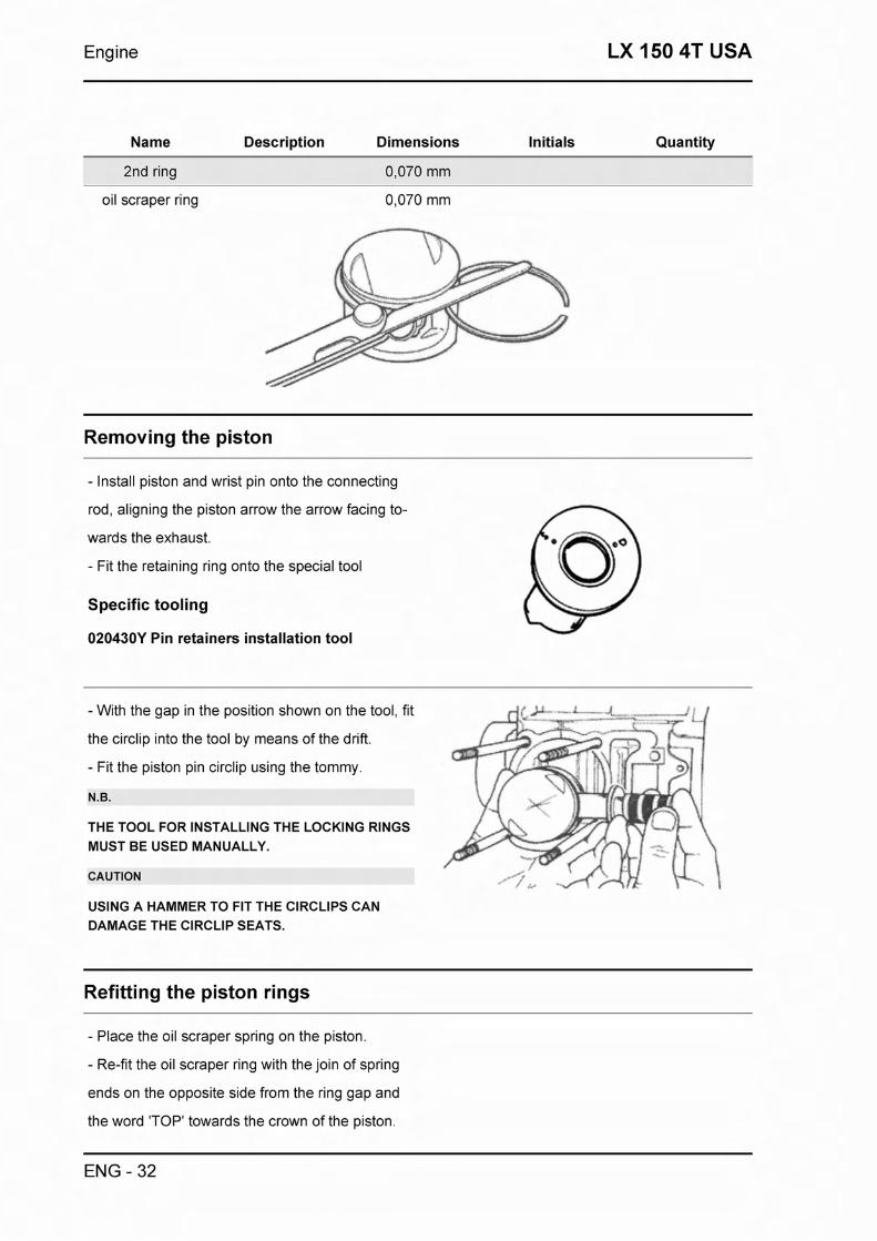
Engine LX 150 4T USA
Name Description Dimensions Initials Quantity
2nd ring 0,070 mm
oil scraper ring 0,070 mm
Removing the piston
- Install piston and wrist pin onto the connecting
rod, aligning the piston arrow the arrow facing to-
wards the exhaust.
- Fit the retaining ring onto the special tool
Specific tooling
020430Y Pin retainers installation tool
-With the gap in the position shown on the tool, fit
the circlip into the tool by means of the drift.
- Fit the piston pin circlip using the tommy.
N.B.
THE TOOL FOR INSTALLING THE LOCKING RINGS MUST BE USED MANUALLY.
CAUTION
USING A HAMMER TO FIT THE ClRCLlPS CAN DAMAGE THE ClRCLlP SEATS.
Refitting the piston rings
- Place the oil scraper spring on the piston.
- Re-fit the oil scraper ring with the join of spring
ends on the opposite side from the ring gap and
the word 'TOP' towards the crown of the piston.
ENG - 32

LX 150 4T USA Engine
The tapered side of the oil scraper ring should al-
ways be facing the crown of the piston.
- Re-fit the middle piston ring with the identifica-
tion letter facing the crown of the piston. The
tapered side of the middle piston ring should al-
ways be facing away from the crown of the piston.
- The top piston ring with the word 'TOP' or the
reference mark facing the crown of the piston.
- Offset the piston ring gaps on the three rings by
120" to each other.
- Lubricate the components with engine oil.
N.B.
IN ORDER TO IMPROVE BEDDING IN OF THE RINGS, THE SURFACES ON THE TOP TO PISTON RINGS ARE ANGLED TO GIVE A CONICAL SEC- TION OF CONTACT.
Refitting the cylinder
- Fit the base gasket of the chosen thickness, pre-
viously determined.
- Using the fork support, available as a special
tool and the piston ring retaining band, re-fit the
cylinder as show in the diagram.
N.B.
BEFORE FITTING THE CYLINDER, CAREFULLY BLOW THE LUBRICATION DUCT AND OIL THE CYLINDER BARREL.
ENG - 33

Engine LX 150 4T USA
Specific tooling
020426Y Piston fitting fork
020427~ Piston Fitting Tool (motor 150)
lnspecting the cylinder head
- Using a trued bar, check that the cylinder head
surface is not worn or distorted.
- Ensure that the camshaft and rocker arm pivot
bearings show no signs of wear.
- Check that the cylinder head cover surface, the
intake manifold and the exhaust manifold are not
worn.
Characteristic
Maximum allowable runout: lnspecting the cylinder head
0,05 mm
STANDARD DIAMETER
Specification Desc.lQuantity
Standard diameter A 0 32,5 + 32,525
Normal diameter B 0 20 + 20,021
Standard diameter
n
lnspecting the timing system components
- Check that the guide shoe and the tensioner
shoe are not worn out.
ENG - 34

LX 150 4T USA Engine
- Ensure that the camshaft drive pulley, the chain
assembly and the pinion are not worn.
- Replace any worn components. If the chain, pin-
ion or pulley are worn, replace the whole as-
sembly.
6
- Remove the central screw and the tensioner
spring. Check that the one-way mechanism is not
worn.
- Check the condition of the tensioner spring.
- If any worn components are found, replace the
whole assembly.
lnspecting the valve sealings
- Measure the width of the sealing surface on the valve seats.
VALVE SEALING SURFACE
Specification DescJQuantity
Intake valve - sealing width 2,4 - 2,8 mm
Exhaust valve - sealing width - 2,2 - 2,6 mm
lnspecting the valve housings
- Remove any carbon formation from the valve guides.
- Measure the inside diameter of each valve guide.
ENG - 35
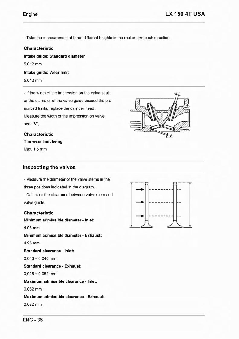
Engine LX 150 4T USA
- Take the measurement at three different heights in the rocker arm push direction.
Characteristic
Intake guide: Standard diameter
5,012 mm
Intake guide: Wear limit
5,012 mm
- If the width of the impression on the valve seat * or the diameter of the valve guide exceed the pre-
scribed limits, replace the cylinder head.
Measure the width of the impression on valve
seat "V",
Characteristic
The wear limit being
Max. 1,6 mm.
Inspecting the valves
- Measure the diameter of the valve stems in the
three positions indicated in the diagram.
- Calculate the clearance between valve stem and
valve guide.
Characteristic
Minimum admissible diameter - Inlet:
4.96 mm
Minimum admissible diameter - Exhaust:
4.95 mm
Standard clearance - Inlet:
0.013 + 0.040 mm
Standard clearance - Exhaust:
0,025 + 0,052 mm
Maximum admissible clearance - Inlet:
0.062 mm
Maximum admissible clearance - Exhaust:
0.072 mm
ENG - 36

LX 150 4T USA Engine
- Check the wear on the surfaces on the ends of
the valve stems, in contact with the tappets, is not OK
excessive.
- If any of the sealing surfaces on the valves does
not conform to the specified wear limits, or is
damaged, or curved, replace the valve with a new
one.
Characteristic
Standard length of the valves - Inlet:
80.6 mm
Standard length of the valves - Exhaust:
79.6 mm
- If no anomalies are found during the above
checks, the same valves can be reused. For best
sealing results, it is advisable to grind the valves.
Grind the valves gently with a fine-grained lapping
compound. During the grinding, keep the cylinder
head in a horizontal position. This will prevent the
lapping compound residues from penetrating
between the valve stem and the guide.
CAUTION
TO AVOID SCORING THE MATING SURFACE, DO NOT KEEP ROTATING THE VALVE WHEN NO LAP- PING COMPOUND IS LEFT. CAREFULLY WASH THE CYLINDER HEAD AND THE VALVES WITH A SUITABLE PRODUCT FOR THE TYPE OF LAPPING COMPOUND BEING USED.
- Insert the valves into the cylinder head.
- Alternately test the intake and exhaust valves.
- The test is carried out by filling the manifold with
petrol and checking that no petrol oozes through
the valves when these are pressed with one fin-
ger.
ENG - 37
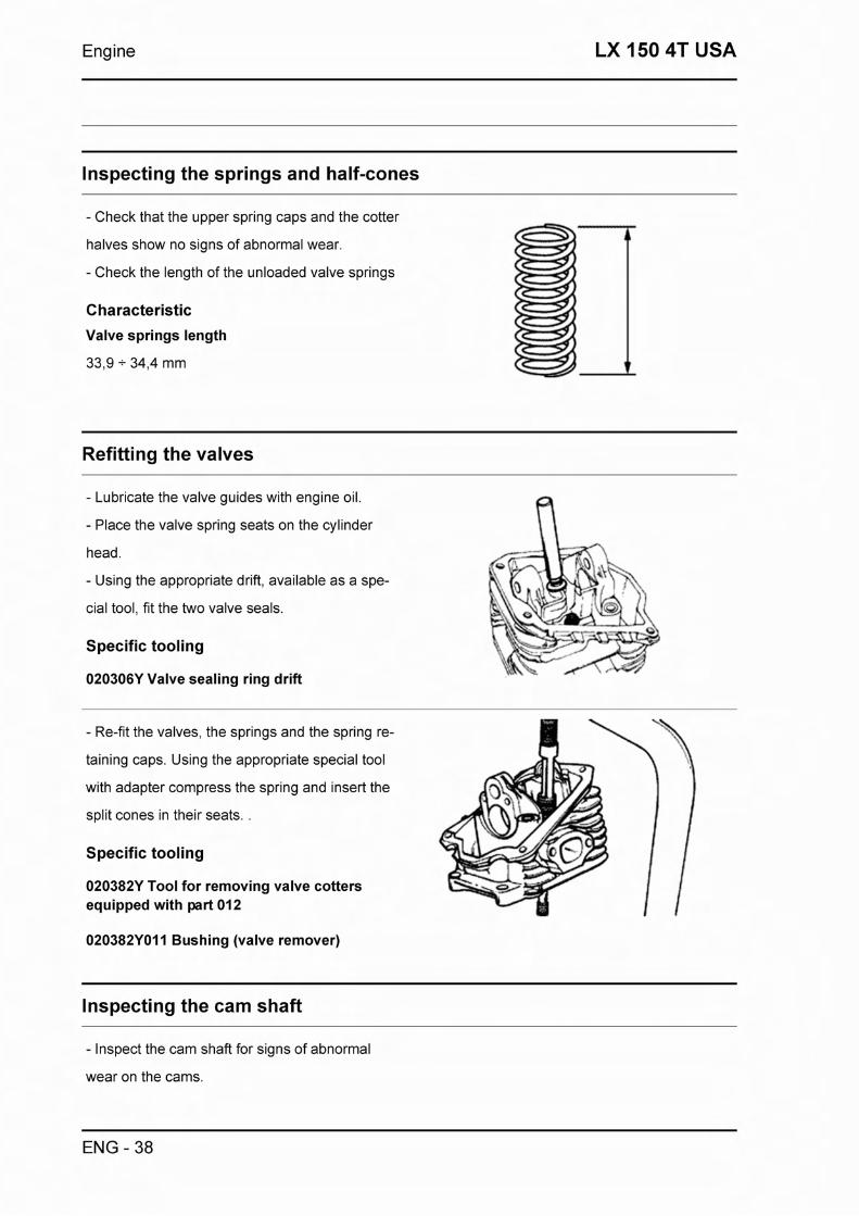
Engine LX 150 4T USA
lnspecting the springs and half-cones
- Check that the upper spring caps and the cotter
halves show no signs of abnormal wear.
- Check the length of the unloaded valve springs
Characteristic
Valve springs length
33,9 + 34,4 mm
Refitting the valves
- Lubricate the valve guides with engine oil.
- Place the valve spring seats on the cylinder
head.
- Using the appropriate drift, available as a spe-
cial tool, fit the two valve seals.
Specific tooling
020306Y Valve sealing ring drift
- Re-fit the valves, the springs and the spring re-
taining caps. Using the appropriate special tool
with adapter compress the spring and insert the A . -
split cones in their seats. .
Specific tooling
020382Y Tool for removing valve cotters equipped with part 012
020382Y011 Bushing (valve remover)
lnspecting the cam shaft
- Inspect the cam shaft for signs of abnormal
wear on the cams.
ENG - 38

LX 150 4T USA Engine
Characteristic
Standard diameter - Bearing surface A
0 : 32,5mm -0,025 -0,050 mm
Standard diameter - Bearing surface B
20 -0,020 -0,041 mm
Minimum admissible diameter - Bearing sur- face A
A
0 : 32.440 mm
Minimum admissible diameter - Bearing sur- face B
Intake cam height
Exhaust cam height
27,212 mm
- Check there is no wear on the cam shaft retain-
ing plate and its associated groove on the cam
shaft.
- If any of the above dimensions are outside the
specified limits, or there are signs of excessive
wear, replace the defective components with new
ones.
Characteristic
Maximum admissible axial clearance:
0.42 mm
- Check there are no signs of wear on the auto-
matic valve-lifter cam, or the end-stop ring, or the
rubber buffer on the automatic valve-lifter retain-
ing cover.
- Check the automatic valve-lifter return spring is
not deformed by over-stretching.
- Replace any defective or worn components.
ENG - 39

Engine LX 150 4T USA
- Check the rocker in for excessive wear or scor-
ing.
-Check there are no signs of wear on the cam fol-
lowers or the tappets.
- Measure the internal diameter of both rockers.
- Check there are no signs of wear on the spring
washers that take up the axial play between the
rockers. Replace any defective components with
new ones.
Characteristic
Minimum admissible diameter:
0 11.970 mm
Maximum admissible diameter:
0 12.030 mm
Refitting the head and timing system components
- Re-fit the timing chain guide.
- Insert the dowel the cylinder head to the cylinder, fit the cylinder head gasket and the cylinder head.
- Fit the cylinder head nut fasteners and tighten them in a crosswise sequence, in two or three
stages, to the specified tightening torque.
Locking torques (N*m)
Tightening torque 28 - 30
- Fit the two screw fasteners on the outside of the
timing chain side of the cylinder head and tighten
them to the specified tightening torque.
N.B.
BEFORE INSTALLING THE HEAD, MAKE SURE THAT THE LUBRICATION CHANNB IS CLEAN US- ING A COMPRESSED AIR JET.
Locking torques (N*m)
Tightening torque 11 - 13
- Re-fit the lower timing chain sprocket on the
ENG - 40

LX 150 4T USA Engine
crankshaft, with the chamfer innermost.
- Loop the timing chain around the sprocket on
the crankshaft.
- Re-fit he chain tensioner guide to the cylinder
head.
- Fit the spacer and the screw fastener.
- Fit the rocker pin, the exhaust rocker, the spring
washer and the inlet washer.
- Lubricate the rockers via the holes on top.
- Lubricate the cam surfaces and insert the cam
shaft in the support, making sure the cams cor-
respond to the rockers.
- Re-fit the cam shaft retaining plate and fit the
two screw fasteners shown in the diagram to the
specified tightening torque.
Locking torques (N*m)
Tightening torque 4 - 6
- Re-fit the spacer on the cam shaft.
- Rotate the engine so that the piston is at TDC,
using the reference marks on the flywheel and the
crankcase.
- Holding the engine in this position, loop the
chain over the cam shaft timing chain sprocket,
making sure the reference mark 2V on the
sprocket corresponds to the reference mark ma-
chined on the cylinder head.
- Fit the pulley on the cam shaft.
- Re-fit the counterweight and tighten the screw
fastener to the specified tightening torque.
Locking torques (N*m)
Tightening torque 7 - 8,5
ENG - 41
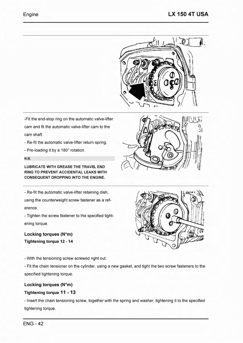
Engine LX 150 4T USA
-Fit the end-stop ring on the automatic valve-lifter
cam and fit the automatic valve-lifter cam to the
cam shaft.
- Re-fit the automatic valve-lifter return spring.
- Pre-loading it by a 180" rotation.
N.B.
LUBRICATE WlTH GREASE THE TRAVEL END RING TO PREVENT ACCIDENTAL LEAKS WlTH CONSEQUENT DROPPING INTO THE ENGINE.
- Re-fit the automatic valve-lifter retaining dish,
using the counterweight screw fastener as a ref-
erence.
- Tighten the screw fastener to the specified tight-
ening torque.
Locking torques (N*m)
Tightening torque 12 - 14
-With the tensioning screw screwed right out.
- Fit the chain tensioner on the cylinder, using a new gasket, and tight the two screw fasteners to the
specified tightening torque.
Locking torques (N*m)
Tightening torque 11 - 13
- Insert the chain tensioning screw, together with the spring and washer, tightening it to the specified
tightening torque.
ENG - 42

LX 150 4T USA Engine
Locking torques (N*m)
Tightening torque 5 - 6
-Adjust the valve clearances according to the in-
structions in Chapter General Information and
Maintenance.
- Re-fit the spark plug.
Electric characteristic
Recommended spark plug:
CHAMPION RG4HC
Spark gap
0.8 mm
Locking torques (N*m)
Tightening torque 12 - 14
- Re-fit the rocker cover gasket. The projections
on the timing chain side provide a reference for its
orientation.
- Re-fit the cooling cover to crankcase screw
fastener, tightening it to the specified tightening
torque, and re-fit the two self-tapping screw
fasteners that hold the cooling cover sides togeth-
er.
- Make sure the rocker cover gasket does not
come out of position.
-Whilst fitting the cover
Locking torques (N*m)
Tightening torque 3 - 4
- Re-fit the inlet duct and tighten the screw fasten-
ers to the specified tightening torque.
- Re-connect the carburettor to the inlet duct and
tighten the hose clamp.
N.B.
ADJUST THE ORIENTATION OF THE CARBURET- TOR BY MEANS OF THE PROJECTION ON THE
ENG - 43

Engine LX 150 4T USA
MANIFOLD.
Locking torques (N*m)
Tightening torque I I - 13
- Re-fit the cylinder head cover, tightening the
four screw fasteners to the specified tightening
torque.
- Re-fit the fan and fan cover.
- Re-fit the oil pump drive, the oil pump cover, the
oil blow-by valve and the sump, as described in
Chapter ((Lubrication>>.
- Re-fit the drive pulley, the drive belt and the
transmission cover, as described in Chapter
((Transmission)).
Locking torques (N*m)
Tightening torque 11 - 13
Crankcase - crankshaft
- Removing the Crankshaft:
Performing the steps described in Chapter Trans-
mission, remove the following: transmission cov-
er, drive pulley, driven pulley, drive belt, reduction
gearbox cover, gears, bearings and oil seals.
- Performing the steps described in Chapter Lub-
rication, remove the following: sump, oil blow-by -- - valve, oil pump drive cover and oil pump.
- Performing the steps described in Chapter Fly-
wheel, remove the following: flywheel cover, fan,
flywheel, stator.
- Remove the oil filter and the oil low pressure
ENG - 44

LX 150 4T USA Engine
sender.
- Performing the steps described in Chapter Cyl-
inder Head and Timing Components, remove the
cylinder head assembly and the cylinder-piston
assembly.
- Remove the two screw fasteners shown in the
diagram and remove the starter motor.
- Before separating the crankcase halves, it is
worthwhile to measure the end-float on the crank-
shaft. Use a dial-gauge and support attached to
the crankcase separating plate, available as a
special tools.
Specific tooling
020262Y Crankcase detachment plate
020335Y Magnetic stand and comparator
Characteristic
Standard clearance
0.15 - 0.40 mm
Splitting the crankcase halves
- Remove the 11 screw fasteners securing the
crankcase halves together.
- Separate the crankcase halves, taking care to
leave the crankshaft supported by one of them.
- Remove the crankshaft.
CAUTION
THE CRANKSHAFT MAY FALL IF THIS PRECAU- TION IS NOT TAKEN.
- Remove the crankcase gasket.
- Remove the two screws and the internal cover
shown in the diagram.
CAUTION
ENG - 45

Engine LX 150 4T USA
WHILE OPENING THE CRANKCASES AND REMOV-
ING THE DRIVING SHAFT, CHECK THAT THE SHAFT THREADED ENDS DO NOT INTERFERE WITH THE BENCH BRASSES. FAILURE TO OB-
SERVE THIS PRECAUTION CAN DAMAGE THE BENCH BRASSES.
- Remove the oil seal on the flywheel side.
- Remove the oil filter union shown in the dia-
gram.
- Check the end-float, before removal.
Characteristic
Standard clearance
0.20 - 0.50 mm
- Check the radial free-play on the connecting
rod.
-Check the surfaces that limit the axial free-play
are not scored and measure the width of the
crankshaft between these surfaces, as shown in
the diagram.
CAUTION
MAKE SURE THE ENDS OF THE CALIPER DO NOT
GO INTO THE MACHINED CORNER ON THE CRANKSHAFT, AS THE CURVATURE IN THE CORNER MAY CAUSE INACCURATE READINGS.
ENG - 46

LX 150 4T USA Engine
Characteristic
Standard clearance
0.036 - 0.054 mm
- Provided none of the specified crankshaft toler-
ances are exceeded, end-float on the crankshaft
found to exceed the specified limit must be due to
either excessive wear or wrong machining on the
crankcase.
CAUTION
BE CAREFUL NOT TO LET THE MEASUREMENT BE AFFECTED BY THE UNIONS WITH THE DRIV- ING SHAFT ENDS.
Characteristic
Distance between supports
55,67 + 55,85 mm
- On both main bearing seats, take two perpendicular measurements of the diameters of the crank-
shaft at the points indicated A and B in the diagram. The crankshaft halves fall into two categories,
Cat. 1 and Cat. 2, according to diameter, as shown in the table below.
STANDARD DIAMETER
Specification DescJQuantity
Category 1 28,998 + 29,004
Category 2 28,004 + 29,010
Inspecting the crankshaft alignment
To install the drive shaft on the support and to
ENG - 47

Engine LX 150 4T USA
measure the misalignment in the 4 points indicate
to you in figure.
- Check that the driving shaft cone, the tab seat,
the oil guard connection and the threaded tangs
are in good working order.
- In case of failures, replace the driving shaft.
The connecting rod head brasses cannot be re- p
placed.
For the same reason, when cleaning the driving
shaft, be careful to prevent any impurity from en-
tering into the shaft lubrication hole.
In order to prevent damaging the connecting rod
brasses, do not attempt cleaning the lubrication
duct with compressed air.
- Make sure that the 2 pads on the crank button
are properly mounted.
- A wrong installation of a pad can seriously affect
the brass lubrication pressure.
N.B.
BENCH ENDS ARE NOT RECTIFIABLE.
Specific tooling
020074Y Crankshaft aligning tool
Characteristic
Alignment check: Max admissible displace- ment:
Inspecting the crankcase halves
- Before proceeding to check the crankcase
halves, thoroughly clean the all surfaces and oil
ducts.
ENG - 48

LX 150 4T USA Engine
- On the transmission side crankcase half, take - particular care cleaning the housing and oil ducts
for the following components: the oil pump, the oil
blow-by valve, the main bearings and the cooling
jet on the transmission side (see diagram). i
- Take particular care, also, that there are no
signs wear oil blow-by valve housing (see I--- - - . - Chapter Lubrication), as this could prevent a good
seal in the valve, which regulates the oil pressure.
N.B.
THE JET IS FED THROUGH THE BENCH BRASSES.
PROPER OPERATION OF THlS COMPONENT IM- PROVES THE PISTON TOP COOLING. CLOGGING HAS EFFECTS THAT ARE DIFFICULT TO DETECT
(PISTON TEMPERATURE INCREASE). FAILURE OR LEAK CAN CONSIDERABLY DECREASE THE BENCH BRASS AND CONNECTING ROD LUBRICA-
TION PRESSURE.
- On the flywheel side crankcase half, take partic-
ular care cleaning the oil ducts for the main bear-
ings, the oil duct for the jet that lubricates the cyl-
inder head and the oil drainage duct at the fly-
wheel side oil seal.
N.B.
THE HEAD LUBRICATION CHANNEL IS PROVIDED
WITH A SHUTTER JET; THlS GIVES A <<LOW PRES- SURED HEAD LUBRICATION; THlS CHOICE WAS MADE TO REDUCE THE OIL TEMPERATURE IN
THE SUMP. THE JET CLOGGING IMPAIRS THE HEAD LUBRICATION AND THE TIMING MECHAN-
ISMS. A JET FAILURE CAUSES A DECREASE OF THE BENCH BRASS AND CONNECTING ROD LUB-
RICATION PRESSURE.
- Inspect the mating surfaces on the crankcase
halves for scratches or deformation, taking partic-
ular with the surfaces that mate with the cylinder
and the mating surfaces between the crankcase
halves.
ENG - 49

Engine LX 150 4T USA
- Defects in the gasket between the crankcase
halves, or the mating surfaces shown in the dia-
gram, can cause a reduction in the oil pressure
lubricating the main bearing and connection rod.
- Check the main bearing seats that limit axial
play in the crankshaft show no signs of wear. The
dimension between these seats is measured by
way of the procedure described previously for
measuring the crankshaft axial play and dimen-
sions.
Inspecting the crankshaft plain bearings
- Proper lubrication of the main bearings depends
on them being seated correctly in their housings, .--
which will avoid obscuring the lubrication ducts.
Not only will this ensure proper flow of oil, but
also the appropriate oil pressure (4 bar), on which
lubrication of the main bearings depends.
- The main bearings comprise two half-bearings,
one containing holes and channels for lubrication
and the other solid.
- The solid half-bearing bears the main load due
to combustion and is, therefore, located at the far
side from the cylinder.
- In order to avoid obstructing the passage of oil,
the plane of the coupling between the two half-
bearings must be absolutely perpendicular to the
axis of the cylinder, as shown in the diagram.
- The depth to which the half bearings are driven,
ENG - 50

LX 150 4T USA Engine
in relation to the surface that limits axial play of
the crankshaft, can also affect the alignment of
the oil ducts.
N.B.
TO KEEP SUCH POSITION OF THE BRASSES ON THE CRANKCASE, DRIVING IS FORCED ON STEEL RINGS INSERTED IN THE CASTING OF BOTH HALF-CRANKCASES.
Characteristic
Standard driving depth
1.35 - 1.6
- Check the inside diameter of the main bearings in the three directions indicated in the diagram.
- Repeat these measurements on the other side of the lubrication channel in the bearing (see dia-
gram).
- The main bearings are chosen from a selection of standard sizes that give certain inside diameters
once driven into the bearing housings in the crankcase, so as to obtain a match with the crankshaft.
- The bearing housings fall are available in two categories, Cat. 1 and Cat. 2, as are the crankshafts.
- The main bearings are available in three thicknesses, identified by colour markings, as shown in the
below table.
N.B.
DO NOT TAKE THE MEASURE ON THE HALF-BEARING MATCHING SURFACE SINCE THE ENDS ARE RELEASED TO ALLOW DEFORMATION UPON INSERTION.
CRANKCASE BEARINGS
Specification Desc.lQuantity
B Blue
C Yellow
Green
ENG - 51

Engine LX 150 4T USA
Refitting the crankcase halves
- Re-fit the internal cover shown in the diagram
and tighten the two screw fasteners to the spe-
cified tightening torque.
Locking torques (N*m)
Tightening torque 4 - 6
- Re-fit the oil filter union and tighten it to the spe-
cified tightening torque.
- Place a new gasket on one of the crankcase
halves, preferably on the transmission side, to-
gether with the locating dowels.
Locking torques (N*m)
Tightening torque 27 - 33
- Lubricate the main bearings and insert the
crankshaft in the transmission side crankcase
half.
- Re-assemble the two crankcase halves.
- Fit the 11 screw fasteners and tighten them to
the specified tightening torque.
N.B.
WHILE ASSEMBLING THE CRANKCASE AND THE CRANKSHAFT, TAKE CARE NOT TO DAMAGE THE THREADED TANGS OF THE CRANKSHAFT.
Locking torques (N*m)
Tightening torque I 1 - 13
- Lubricate the flywheel side oil seal.
- Using the appropriate special tool fit the oil seal.
- Fit a new O-ring on the oil sieve and lubricate it.
- Re-fit the oil seal to the engine with the oil drain
plug and tighten to the specified tightening torque.
ENG - 52

LX 150 4T USA Engine
N.B.
REMOVE ANY REMAINS OF THE OLD GASKET FROM THE CRANKCASE AND CYLINDER MATING SURFACES IN ORDER TO ENSURE PROPER SEALS
N.B.
FAILURE TO USE THE SPECIFIC TOOL MAY RES- ULT IN THE OIL SEAL BEING DRIVEN TO AN UN- SUITABLE DEPTH, WHICH WOULD CAUSE THE OIL SEAL TO MALFUNCTION.
Specific tooling
020425Y Flywheel-side oil guard punch
Locking torques (N*m)
Tightening torque 24 - 30
Lubrication
Conceptual diagrams
ENG - 53

Engine LX 150 4T USA
-. . --. %.-:-- -~-- - - - - - 0
0 , . . ., . .-_ . . - .-. P .TWl -*lIT L r.' . ? , ~ - R F j - * - a ? { b ? . .. , . . 8
3 ,: ' L , .& -- , b P t b - 9 - I*,
4, ' -, ; - 1 4 . .- . Pfwa rw?. : .
. . . . - . ,. l-'-qL 1'7 *:cm> P4 [L 1 B 1-8-
" . _ .. - - - - - . - - . - -
- . ? . . - - - - u 1 . - - - , -
. , rT:TFf- kc.- &,-a-
Oil pressure check
ENG - 54

LX 150 4T USA Engine
- Remove the fan cover, as described in the last
chapter, "Flywheel", disconnect the oil low pres-
sure warning sender wires and remove the
sender itself.
- Check the oil pressure reading is between 0.5
and 1.2 atm with the engine at the slow running
speed of 1650 r.p.m. and an oil temperature of
around 90°C.
- Check the oil pressure reading is between 3.2
and 4.2 atm with the engine running at a speed
6000 r.p.m. and an oil temperature of around
90°C.
- Remove the compression gauge once the
measurement is complete and re-fit the oil pres-
sure sensor, tightening it to the specified tighten-
ing torque, and re-fit the fan cover.
- If the oil pressure is outside the specified limits,
in the following order, check: the oil filter, the oil
blow-by valve, the oil pump and the crankshaft
seals.
N.B.
THE CHECK MUST BE CARRIED OUT WlTH OIL AT THE CORRECT LEVEL AND WlTH AN OIL FILTER IN GOOD CONDITIONS.
Characteristic
Minimum pressure
3.2 bar
Locking torques (N*m)
Tightening torque 12 - 14 (also applicable to compression gauge fitting)
Crankshaft oil seals
Removal
- Remove the transmission cover and complete
ENG - 55

Engine LX 150 4T USA
driving pulley beforehand
- Install the base of the special tool on the oil seal T ; ' ~
using the screws provided.
I
I /' - - Screw the threaded bar onto the base of the tool
and extract the oil seal. FSS&< . \- .
Specific tooling
020622Y Transmission-side oil guard punch . .. 1
Refitting
I - Prepare the new oil seal lubricating the sealing
surface. Note: do not lubricate the surface mating
with the crankcase.
CAUTION
DO NOT LUBRICATE THE SURFACE KEYED ON THE ENGINE CRANKCASE.
a- - ? --.
- Preassemble the oil seal using the special tool.
- Insert the sheath onto the crankshaft.
ENG - 56

LX 150 4T USA Engine
-F
- Insert the tool with the oil seal on the crankshaft - .r---TT4 I 1 ,/q-:\ 1
until it comes into contact with the crankcase. -' (61 , CAUTION
ORIENTATE THE OIL GUARD BY POSITIONING THE CHAIN HOUSING CHANNL FACING DOWN- WARDS. WHEN THE POSITION IS REACHED, DO I . - NOT RETRACT THE OIL GUARD. FAILURE TO COMPLY WITH THIS RULE CAN CAUSE A WRONG POSITIONING OF THE OIL GUARD SHEATH.
- Orientate the oil seal installing the bracket com- I -
prising the special tool. I
- Tighten the threaded bar onto the crankshaft as I--- -
far as it will go.
- Using the nut, act on the base of the tool as far
as it will go.
ENG - 57

Engine LX 150 4T USA
- Remove all of the tool components following the inverse procedure
CAUTION
FAILURE TO COMPLY WITH THIS ASSEMBLY PROCEDURE CAN SERIOUSLY DAMAGE THE ENGINE DUE TO THE WRONG TENSIONING OF THE OIL PUMP CONTROL CHAIN.
Assemble a new oil guard on the magneto side
using the specific tool as indicated in the photo.
N.B.
FAILURE TO USE THE SPECIFIC TOOL MAY RES- ULT IN THE OIL SEAL BEING DRIVEN TO AN UN- SUITABLE DEPTH, WHICH WOULD CAUSE THE OIL SEAL TO MALFUNCTION.
Specific tooling
020425Y Flywheel-side oil guard punch
Oil pump
Removal
- Remove the two screw fasteners of the lower oil
pump chain cover, shown in the diagram, and re-
move the cover itself.
- Block the rotation of the lower oil pump sprocket
with a screwdriver inserted through one of its two
holes.
- Remove the central screw fastener with dished
ENG - 58

LX 150 4T USA Engine
washer, as shown in the diagram.
- Remove the sprocket and the chain.
- Remove the oil pump drive cog from the crank-
shaft.
- Undo the two oil pump screw fasteners, shown
in the diagram, extract the oil pump.
- Remove the oil pump seal.
CAUTION
THE CHAIN SHOULD BE MARKED TO ENSURE THAT THE ORIGINAL DIRECTION OF ROTATION IS MAINTAINED.
Inspection
- Remove the two screw fasteners on the rear of
the pump and remove its cover.
- Remove the circlip retaining the innermost im-
peller.
- Remove and wash the impellers thoroughly with
petrol and compressed air.
- Reassemble the impellers in the pump body,
keeping the two reference marks visible, and re-
place the circlip.
- Check the clearance between the impellers us-
ing feeler gauges, as shown in the diagram.
Characteristic
Maximum allowable clearance:
0.12 mm
ENG - 59

Engine LX 150 4T USA
Measure the distance between the outer rotor and
the pump body (see figure).
Characteristic
Maximum allowable clearance:
0.20 mm
- Check the axial play in the rotors using a flat
surface as a reference plane, as shown in the dia-
gram.
Characteristic
Maximum allowable clearance:
0.09 mm
Refitting
- Check there are no signs of wear on the oil
pump shaft or body.
- Check there are no signs of scoring or wear on
the oil pump cover.
-Substitute any defective parts or the complete oil
pump assembly, as appropriate.
- Re-fit the sprocket on the pump, the central
screw, tightened to the specified tightening
torque, and the dished washer.
ENG - 60

LX 150 4T USA Engine
-Re-fit the lower oil pump sprocket cover, tighten-
ing the two screw fasteners to the specified
torque.
N.B.
FIT THE BELLEVILLE WASHER SO THAT ITS OUT- ER (CURVED) RIM IS IN CONTACT WITH THE PUL- LEY.
Locking torques (N*m)
Central screw tightening torque 12 - 14 N-m Cover screw tightening torque 0.7 - 0.9 N-m
Removing the oil sump
- Remove the oil filler plug, the transmission cov-
er, the complete drive pulley assembly, the drive
belt and the bendix, as described in chapter
Transmission.
- Drain the oil as described in chapter General In-
formation and Servicing.
- Remove the seven screw fasteners, shown in
the diagram, and the two rear brake cable
clamps.
- Remove the spring, the blow-by valve plunger
and the gasket shown in the diagram.
Inspecting the by-pass valve
- Check the free length of the spring.
- Check that the piston exhibits no scratches.
- Ensure that it slides freely on the crankcase and
that it guarantees a good seal.
- If not, eliminate any impurities or replace defect-
ENG - 61

Engine LX 150 4T USA
ive parts.
Characteristic
Check by-pass: Standard length
54.2 mm
Refitting the oil sump
- Re-fit the blow-by valve plunger in its housing.
- Insert the pressure-regulating spring.
- Fit a new sump seal.
- Re-fit the sump, taking care to locate the spring
in the appropriate recess machined into the inside
of the sump.
- Re-fit the screw fasteners and the rear brake
cable brackets in the reverse order to which they
were removed.
- Tighten the screw fasteners to the specified
tightening torque.
- Re-fit the drive pulley assembly, the drive belt,
the bendix and the transmission cover, as de-
scribed in chapter "Transmission".
-When testing the lubrication system, refer to
chapter "Crakcase and Crankshaft", regarding
lubrication of the crankshaft and connecting
rod
Locking torques (N*m) Tightening torque 11 - 13
Fuel supply
- Disconnect the fuel feed pipe and the vacuum
pipe from the carburettor.
ENG - 62

LX 150 4T USA Engine
- Ensure that no fuel is leaking from the pipes.
- Close the fuel outlet.
- Using the MI W A C pump, apply a 0.1 bar va-
cuum to the cock.
- Ensure that the vacuum does not change, and
that no fuel is leaking.
- Reconnect the vacuum pipe to the manifold.
- Position the fuel pipe so that its outlet is on the
same level as the cock.
- Make the engine turn by operating the starter
motor for five seconds with the carburettor in the
idle position
- Gather the fuel in a graduated burette.
N.B.
THE MEASUREMENT MAY BE ALTERED BY AN UNSUITABLE ENGINE SPEED OR BY INCORRECT POSITIONING OF THE PIPE. IN THAT CASE, A RE-
DUCED FUEL DLlVERY IS GENERALLY OB- TAINED. THE VACUUM HOLE ON THE MANIFOLD HAS AN INTENTIONALLY REDUCED CROSS-
SECTIONAL AREA IN ORDER TO IMPROVE THE VACUUM PULSES AND ENSURE CONSTANT DE- LIVERY OF THE COCK.
Specific tooling
020329Y Pump MITYVAC
Characteristic
Minimum delivery
20 cc
- Drain the fuel from the tank.
- Remove the fuel delivery pipe and the vacuum 8 pipe.
- Release the clamp and remove the cock.
- Clean the tank and the cock filter with a suitable
solvent.
- Refit the cock taking care to verify the presence d -
of the O-ring.
ENG - 63

Engine LX 150 4T USA
- Turn the cock in the same direction as before
the removal and then tighten the clamp.
N.B.
THE FILTER CAN BE SCREWED OFF THE COCK TO FACILITATE THE CLEANING.
Removing the carburettor
- To remove the carburetor from the engine, the
air filter must be moved and remove the throttle,
automatic starter connection, band securing the
carburetor to the filter box and intake manifold,
the air supply hose to the diaphragm, heater and
induction coupling.
Remove the guard, the bracket and the starter by 1 b
releasing the screw shown in the figure.
Remove the 2 screws and the starter support with
the gasket.
Remove the clamp and the cap with the mem-
ENG - 64

LX 150 4T USA Engine
brane chamber aeration filter.
Remove the 4 fixing screws shown in the figure
and the vacuum chamber cover
WARNING
DURING THE COVER REMOVAL, BE CAREFUL TO THE SUDDEN PROJECTION OF THE SPRING.
Remove the vacuum valve with the membrane.
Loosen the coupling by 118 turn and remove it, re-
move the spring and the vacuum valve pin
ENG - 65
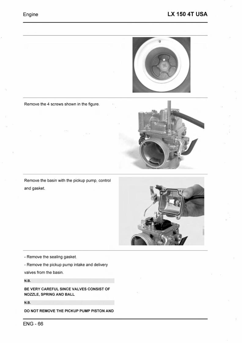
Engine LX 150 4T USA
Remove the 4 screws shown in the figure.
Remove the basin with the pickup pump, control
and gasket.
- Remove the sealing gasket.
- Remove the pickup pump intake and delivery
valves from the basin.
N.B.
BE VERY CAREFUL SINCE VALVES CONSIST OF NOZZLE, SPRING AND BALL
N.B.
DO NOT REMOVE THE PICKUP PUMP PISTON AND
ENG - 66
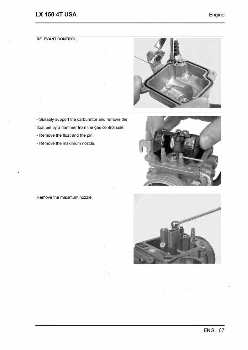
LX 150 4T USA Engine
RELEVANT CONTROL.
- Suitably support the carburettor and remove the
float pin by a hammer from the gas control side.
- Remove the float and the pin. 1
- Remove the maximum nozzle.
I , f
Remove the maximum nozzle.
ENG - 67
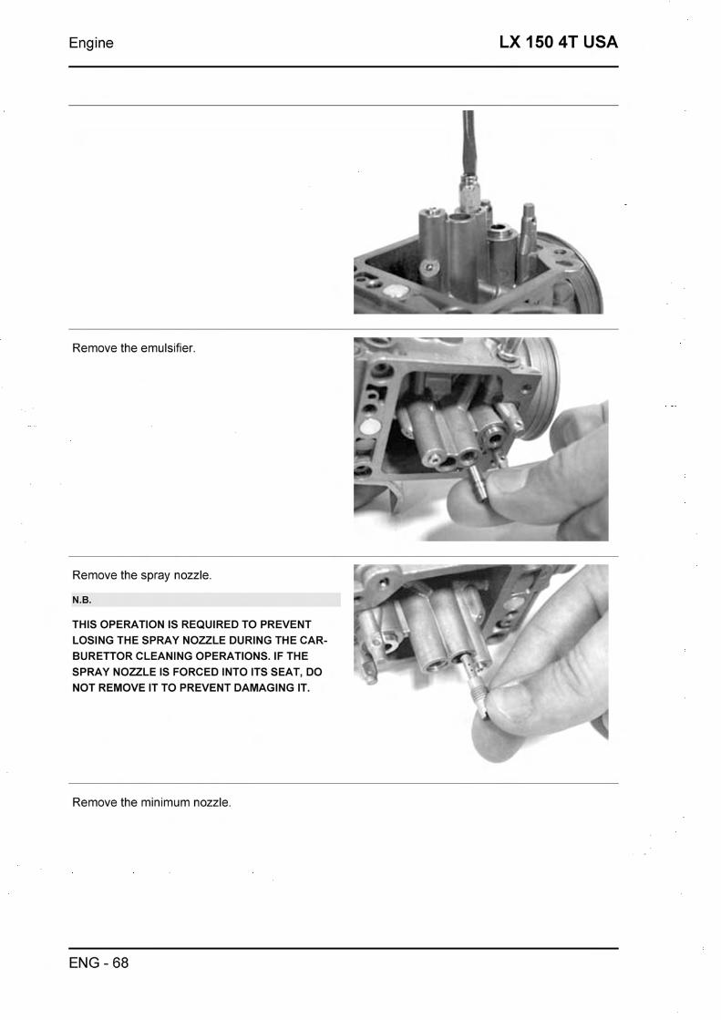
Engine LX 150 4T USA
Remove the emulsifier
Remove the spray nozzle.
N.B.
THIS OPERATION IS REQUIRED TO PREVENT I - I ,.
LOSING THE SPRAY NOZZLE DURING THE CAR- 1 BURETTOR CLEANING OPERATIONS. IF THE 5 - SPRAY NOZZLE IS FORCED INTO ITS SEAT, DO NOT REMOVE IT TO PREVENT DAMAGING IT.
Remove the minimum nozzle.
ENG - 68
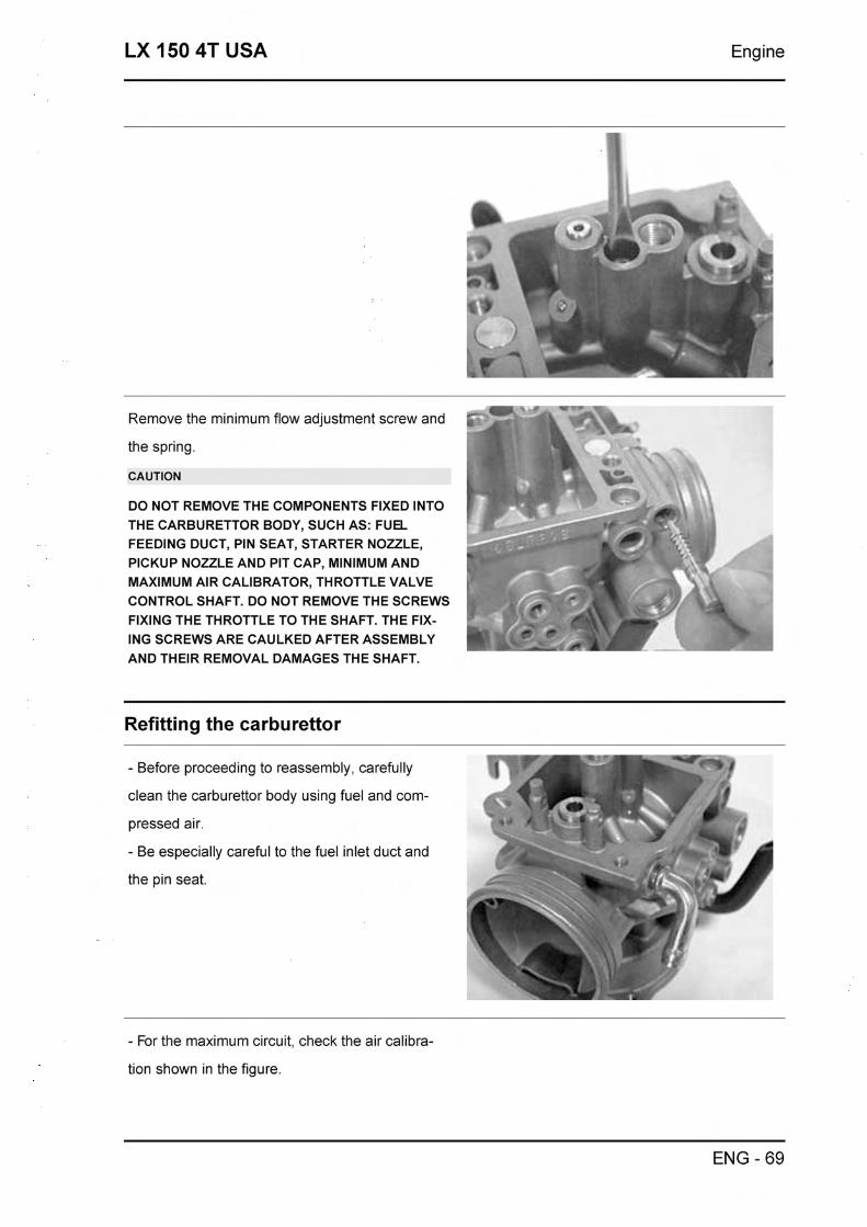
LX 150 4T USA Engine
Remove the minimum flow adjustment screw and
the spring. I
CAUTION I DO NOT REMOVE THE COMPONENTS FIXED INTO I THE CARBURETTOR BODY, SUCH AS: FUEL FEEDING DUCT, PIN SEAT, STARTER NOZZLE,
PICKUP NOZZLE AND PIT CAP, MINIMUM AND i a MAXIMUM AIR CALIBRATOR, THROTTLE VALVE
CONTROL SHAFT. DO NOT REMOVE THE SCREWS 1 FIXING THE THROTTLE TO THE SHAFT. THE FIX-
\ ING SCREWS ARE CAULKED AFTER ASSEMBLY C\ AND THEIR REMOVAL DAMAGES THE SHAFT.
Refitting the carburettor
- Before proceeding to reassembly, carefully
clean the carburettor body using fuel and com-
pressed air.
- For the maximum circuit, check the air calibra-
tion shown in the figure.
ENG - 69
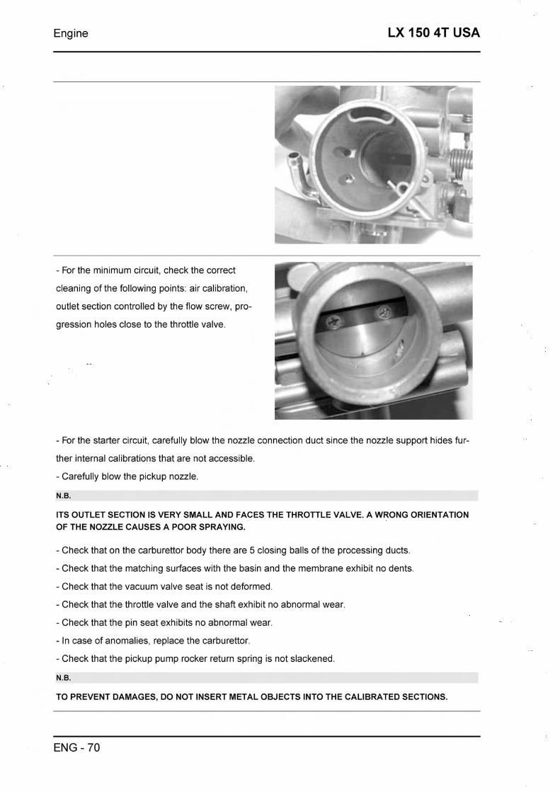
Engine LX 150 4T USA
r -- - For the minimum circuit, check the correct 4
cleaning of the following points: air calibration,
outlet section controlled by the flow screw, pro-
gression holes close to the throttle valve.
- For the starter circuit, carefully blow the nozzle connection duct since the nozzle support hides fur-
ther internal calibrations that are not accessible.
- Carefully blow the pickup nozzle.
N.B.
ITS OUTLET SECTION IS VERY SMALL AND FACES THE THROTTLE VALVE. A WRONG ORIENTATION OF THE NOZZLE CAUSES A POOR SPRAYING.
- Check that on the carburettor body there are 5 closing balls of the processing ducts.
- Check that the matching surfaces with the basin and the membrane exhibit no dents.
- Check that the vacuum valve seat is not deformed.
- Check that the throttle valve and the shaft exhibit no abnormal wear
- Check that the pin seat exhibits no abnormal wear
- In case of anomalies, replace the carburettor.
- Check that the pickup pump rocker return spring is not slackened.
N.B.
TO PREVENT DAMAGES, DO NOT INSERT METAL OBJECTS INTO THE CALIBRATED SECTIONS.
ENG - 70
LX 150 4T USA Engine
-Wash and blow the minimum nozzle and then
replace it.
-Wash and blow the components of the maxim-
um, emulsifier and nozzle circuit.
- Insert the spray nozzle into the carburettor body
with the shorter cylindrical part facing the emulsifi-
er.
- Install the emulsifier making sure that the spray
nozzle is properly inserted, then lock it.
- Install the maximum nozzle.
- Check that the conical pin exhibits no wear on
the pin sealing surface and on the return spring.
- In case of wear, replace the pin.
- Check that the float exhibits no wear on the pin seat or on the plate in contact with the pin, or fuel
infiltrations.
- In case of anomalies, replace.
- Insert the float with the pin on the fuel feeding side.
N.B.
BE CAREFUL TO THE PROPER INSERTION OF THE RETURN SPRING ON THE FLOAT PLATE.
- Remove the basin drainage screw and wash
ENG - 71
Engine LX 150 4T USA
and blow the basin, be especially careful to the
cleaning of the pickup pump ducts.
- Repeatedly actuate the pickup pump piston and
blow with compressed air
- Replace the pickup pump valves in a sequence:
INTAKE VALVE (A)
Spring
Sphere
Nozzle
DELIVERY VALVE (M)
Spring
Nozzle
Sphere
N.B.
THE DELIVERY VALVE NOZZLE IS PROVIDED WITH A MILLING.
- Check the screw seal by pouring a small amount
of fuel into the basin.
- Install a new gasket on the basin.
- Install the basin on the carburettor body and
tighten the 4 screws.
- Check that the control roller is free to rotate into
its seat.
N.B.
CHECK THE PROPER INSERTION OF THE GAS- KET.
N.B.
AVOID ANY DEFORMATION OF THE PICKUP PUMP CONTROL ROCKER.
- Wash and blow the flow screw.
- Check that the screw is free from deformation
and/or oxidation.
- Assemble the spring on the screw.
ENG - 72

LX 150 4T USA Engine
- Tighten the flow screw on the carburettor body.
- The final position of the screw must be defined by the exhaust gas analysis.
- Prepare the carburettor for adjustment with the screw loosened by 2 turns from the closed position.
Level check
- Place the carburettor tilted as shown in the fig- r; I
ure.
- Check that the reference on the float is parallel to the basin matching surface.
- If the position is different, change the orientation of the metal pin control plate to obtain the position
described above.
Inspecting the valve and needle
- Check that the vacuum valve conical pin is free
from wear.
- Check that the vacuum valve exhibits no
scratches on the outside surfaces.
- Check that the vacuum feeding hole is not
clogged.
- Check that the membrane is not broken or
hardened, if not so, replace the entire valve.
- Insert the conical pin into the vacuum valve
ENG - 73

Engine LX 150 4T USA
seat.
- Replace the vacuum gas valve on the carburet-
tor body being careful to insert the pin into the
spray nozzle.
N.B.
THE VALVE CAN BE INSERTED IN A SINGLE POSI- TION ONLY.
- Replace the spring with the pin lock.
- Replace the vacuum chamber cover checking
the proper positioning of the spring into the hous-
ing on the cover.
- Tighten the screws at the prescribed torque.
Locking torques (N*m)
Vacuum chamber cover screws: XX N m
-Wash and blow the ambient pressure inlet filter
sponge.
- Replace the filter and its clamp.
ENG - 74

LX 150 4T USA Engine
-Wash and blow the starter support.
- Install a new gasket on the carburettor body and
tighten the 2 fixing screws.
Inspecting the automatic choke device
- Check that the automatic starter piston exhibits
no scratches or oxidation.
- Check that the piston slides freely into the seat.
- Check that the piston sealing gasket exhibits no
deformations.
- The starter must be more or less inserted ac-
cording to the ambient temperature.
- Measure the projection of the piston as shown in *
the figure, and check the corresponding value.
- Ensure that the starter settles at ambient tem-
perature.
- The starter should gradually disconnect by the
electric heating.
- Check the starter resistance when settled at am-
ENG - 75
Engine LX 150 4T USA
bient temperature.
- Using a 12V battery, power the automatic starter
and check that the piston reaches the maximum - - r
protrusion. &- - The actual heating time depends on the ambient B - -
- ~
temperature.
- If you detect projections, resistance or times dif- I
fering from those prescribed, replace the com-
plete starter. - - Install the starter on the carburettor checking the
proper positioning of the 0-Ring, insert the plate -. -
with the knurling resting against the starter, tight- 1 7
en the fixing screw.
- Orientate the starter as in the figure.
- Install the safety casing.
N.B.
TO PERFORM THlS CHECK, BE CAREFUL NOT TO GENERATE ANY SHORT CIRCUITS. TO THlS PUR- 1 7 - .-
POSE, USE A CABLE WITH SUITABLE TERMINAL FOR CONNECTING TO THE STARTER.
Characteristic
Automatic starter check Kehin
XX + XX mm at about 20°C
Automatic starter check Kehin maximum pro- jection
XXX + XXX mm
Automatic starter check Kehin max time
5 min
Adjusting the idle
- The engine does not require frequent adjust-
ment of the idle, however it is important that this
adjustment be made in complete compliance with
a few rules.
- Before adjusting the carburettor make sure that
ENG - 76

LX 150 4T USA Engine
the following conditions are met: good lubrication,
valve play and distribution timing conform, spark
plug in excellent conditions, air filter clean and
sealed, exhaust system completely sealed. -
Warm up the engine for at least 5 minutes at
around 50 Kmlh.
- Connect the vehicle to an exhaust analyser in-
serting the analyser probe into a extension hose
fitted airtight to the outlet of the silencer.
- Connect the thermometer of the multimeter
(020331~) to the sump, using the oil cap specific-
ally made for insertion of the probe.
- Start the engine before adjusting the idle speed,
making sure the oil temperature is between 70 -
80 "C.
- Using the analyser revolution counter or a sep-
arate one (020332y), adjust the idle until obtain-
ing a speed of 1600 - 1700 rpm.
-Adjust the flow screw until obtaining a percent-
age of carbon monoxide (CO) of 3.1
- 4.5%, by loosening the screw the CO value in-
creases (rich mixture) by tightening the CO value I.- decreases (thin mixture).
- If correction of the flow screw position leads to
an increase in speed, adjust the revolutions again
and if necessary the flow screw until stabilised
values are achieved.
- Idle carburetion is considered correct when the
values of oil temperature, number of revolutions
and percentage of carbon monoxide are correct.
Additional information can be obtained from the
analyser:
- the percentage of carbon dioxide (C02), the
percentage of carbon dioxide has a reverse trend
compared to the percentage of (CO), values
ENG - 77
Engine LX 150 4T USA
above 12.5% are considered correct. Values out
of this range are considered as an indication of a
non-airtight condition on the exhaust system.
- Unburnt hydrocarbons (HC) are measured in
parts per million (PPM), the value of the HC de-
creases with increased rpm, with the engine idling
it is normal to measure 200
- 400 PPM, these exhaust values are considered
normal for an engine with motorcycle distribution
diagram. Much higher values can be caused by
engine misfiring due to a too thin mixture (low
CO), ignition defects or incorrect distribution tim-
ing or a stuck or non-airtight exhaust valve.
- If the CO is difficult to adjust, carefully check:
- Cleaning of the carburettor
- Correct working order of the automatic starter
- Correct working order of the tapered pin-seat
- Bowl level
N.B.
THE EXTENSION PIPE IS REQUIRED TO AVOID WITHDRAWING EXHAUST GAS FROM THE AMBI- ENT OXYGEN. USE A GAS ANALYSER WARMED IN ADVANCE AND CAPABLE OF ENSURING THE RE- SET OF THE GAS READING AND A CORRECT GAS RATE. FAILURE TO COMPLY WITH THESE RULES MAY GIVE A WRONG READING.
N.B.
THE IGNITION SYSTEM IS OF THE SPARK TYPE AND HAS A VERY HlGH POWER. USING WRONG RPM COUNTERS MAY CAUSE DIFFICULTIES IN THE READING. THE RPM COUNTER MATCHING IS CORRECT WHEN IT CAN READ HlGH SPEEDS TOO, SUCH AS 6,000 - 8,000 RPM.
Characteristic
Engine idle: Pipe dimensions
0 40 mm
Engine idle: Length
500 + 600 mm
ENG - 78

LX 150 4T USA Engine
ENG - 79

Engine LX 150 4T USA
ENG - 80


Suspensions LX 150 4T USA
Sospensioni anteriore
This section describes the operations which can be carried out on the suspensions.
Front
Removing the front wheel
-Remove the five socket-head screws fastening
the wheel to the hub.
N.B.
REMOVE THE BRAKE CALLIPER BEFORE REMOV- ING THE WHEEL HUB.
Front wheel hub overhaul
- Remove the ball bearing lock snap ring shown in A
\
the figure C C . u
"a -.*. AL
Using the specific tool, remove the ball bearing.
Specific tooling
001467Y014 15 mm pliers
001467Y017 Bell for bearings external 0 39 mm
- Using a screwdriver, remove the oil guard on the
roller bearing side.
SUSP - 2
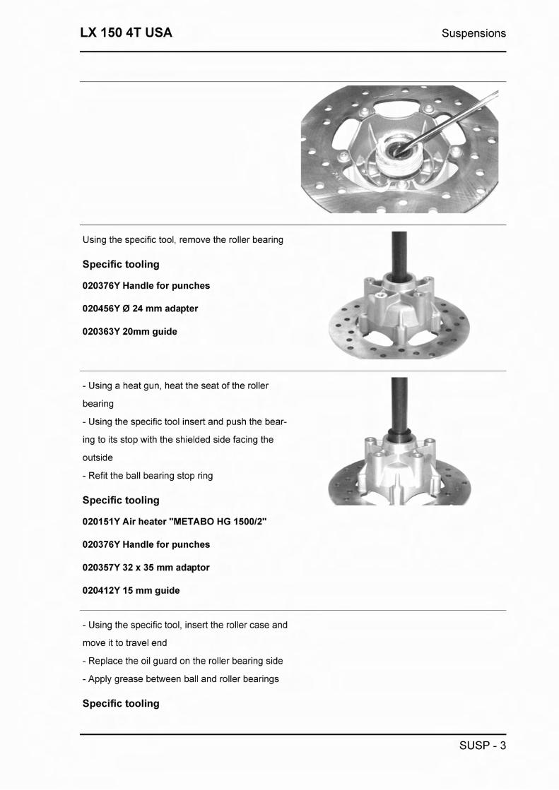
LX 150 4T USA Suspensions
Using the specific tool, remove the roller bearing
Specific tooling
020376Y Handle for punches
020456Y 0 24 mm adapter
020363Y 20mm guide
- Using a heat gun, heat the seat of the roller
bearing
- Using the specific tool insert and push the bear-
ing to its stop with the shielded side facing the R .-
outside
- Refit the ball bearing stop ring
Specific tooling
020151Y Air heater "METABO HG 150012"
020376Y Handle for punches
020357Y 32 x 35 mm adaptor
020412Y 15 mm guide
- Using the specific tool, insert the roller case and
move it to travel end
- Replace the oil guard on the roller bearing side
- Apply grease between ball and roller bearings
Specific tooling
SUSP - 3

Suspensions LX 150 4T USA
020038~ Drift
Recommended products
JOTA 3 FS Speedometer transmission
Lithium soap grease NLGl 33
Refitting the front wheel
- Reassembly, tighten the five screws to the pre-
scribed torque.
Locking torques (N*m)
Nut tightening torque 20 + 25 N-m
Handlebar
Removal
- Before proceeding, remove the handlebar fair-
ing.
- After detaching flexible transmission cables and
disconnecting electrical terminals, loosen the
clamp securing the handlebar to the steering tube
- Check all components and replace any dam-
aged or defective parts.
N.B.
IF YOU ARE REMOVING THE HANDLEBAR ONLY SO THAT YOU CAN THEN REMOVE THE STEERING ASSEMBLY, SIMPLY ALLOW THE HANDLEBAR TO TIP OVER THE FRONT OF THE SCOOTER, TAKING CARE THAT FLEXIBLE TRANSMISSION CABLES ARE NOT DAMAGED.
SUSP - 4

LX 150 4T USA Suspensions
Refitting
Follow the operations for removal in reverse, ob- I
serving the prescribed tightening torques. 1 LC-
Locking torques (N*m)
Handlebar fastening screw 45 + 50 N-m
Steering column
Removal
After removing the top seat, tilt the vehicle on a
side and extract the steering tube with fork.
Specific tooling
020055Y Steering tube ring nut spanner
Overhaul
- Use the tool equipped with parts 3 and 4 and
turn the tool handle until the washers are wedged
into the trailing link.
- Remove spacers, part 17, and pack the clear-
ance between the steering tube and the trailing
link with grease. Now slide the dust seals into po-
sition.
* Supplied with the tool
N.B.
THE LOWER SEAT ON THE STEERING COLUMN TUBE MUST BE MOUNTED WITH THE HELP OF A
SUSP - 5

Suspensions LX 150 4T USA
CROP END WITH AN APPROPRIATE DIAMETER.
Specific tooling
020021y Front suspension overhaul kit
001330Y Steering seat installer, to be fitted with parts: 001330Y009-For lower seat, 001330Y013-For upper seat
Recommended products
ZETA 2 Grease for steering wheel bearings and pin seats
Lithium soap and zinc oxide grease NLGI 2
-Lubricate the oil seals with mineral oil and half-fill
the needle bearings with grease.
-Fit the oil seal and the needle bearing on the pin,
complete with retaining washer.
-Remove the special tool and then remove part 5
(guide) which was partially expelled in the previ-
ous assembly step. Leave part 4* mounted on the
tool.
-Remove part 3 from the tool and replace it with
part 16".
-Turn the tool handle to insert the retaining wash-
er - needle bearing - seal ring assy. until part 16
comes into contact with the trailing link.
- To fit the second retaining washer - needle bear-
ing - seal ring assy. repeat the above operation
with the tool on the opposite side to that shown in
the figure, still equipped with part 16 and with part
22* instead of part 4.
* supplied with the tool
Specific tooling
020021y Front suspension overhaul kit
Recommended products
ZETA 2 Grease for steering wheel bearings
SUSP - 6

LX 150 4T USA Suspensions
and pin seats
Lithium soap and zinc oxide grease NLG12
- Fit the two dust seals ccC~ on the trailing link as
shown in detail ((AD.
- Connect the trailing link to the steering tube by
means of guide pin 5*.
- Apply the special tool equipped with part 3* on
the shaft and part 4* at the bottom.
- Smear 22 grease on the pin and insert it into the
trailing link and turn the tool handle until part 3
locates against the steering tube.
-After fitting the pin, insert the two spacers, part
17*, by tapping lightly with a mallet (see following
figure).
* supplied with the tool
Specific tooling
020021y Front suspension overhaul kit
Recommended products
ZETA 2 Grease for steering wheel bearings and pin seats
Lithium soap and zinc oxide grease NLG12
-Use the special tool equipped with parts 20* and
21* as shown in the figure.
-Turn the handle to force the base of the needle
bearings into contact with the end of the pin.
- Apply the special tool fitted with part I * and turn
SUSP - 7

Suspensions LX 150 4T USA
the handle until both the pin and the needle bear-
ing opposing the force exerted by the tool are ex-
pelled at the same time.
- To remove the second needle bearing, fit the
tool with part 2* working from the side opposite to
the one shown in the figure.
* supplied with the tool . .,
Specific tooling
020021y Front suspension overhaul kit
- Overhauling the front suspension serves to renew the parts connecting the steering tube and the
trailing link. This operation is only effective if both steering tube and trailing link are in perfect condi-
tion.
- Crush the retaining washer and remove it by
means of a punch.
- Repeat the operation for the second washer us-
ing the punch on the opposite side to the one /" shown in the figure.
A = Punch 012
B = Sharp edge end
Refitting CAUTION
REASSEMBLE WITH NEW ROLLER BEARINGS, PIN, OIL SEALS AND DUST SEALS.
When assembling the steering tube apply the re-
commended grease on the steering fifth wheel.
Tighten lower ring nut "A" and upper ring nut "B"
to the prescribed torque.
SUSP - 8

LX 150 4T USA Suspensions
Recommended products
TUTELA ZETA 2 Grease for steering, seats of A P
pin and swing arm * , I 1
Lithium soap and zinc oxide grease NLG12 .. . e.
Locking torques (N*m)
Steering lower ring nut 8 + 10 Steering upper ring nut 35 + 40
Front shock absorber
Removal
- Remove the steering tube
- Remove the shock absorber bottom fixing
screws
- Remove the top shock absorber attachments
SUSP - 9
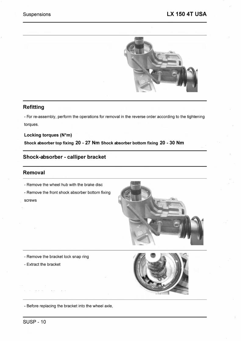
Suspensions LX 150 4T USA
Refitting
- For re-assembly, perform the operations for removal in the reverse order according to the tightening
torques.
Locking torques (N*m)
Shock absorber top fixing 20 - 27 Nm Shock absorber bottom fixing 20 - 30 Nm
Shock-absorber - calliper bracket
Removal
- Remove the wheel hub with the brake disc m -.
- Remove the front shock absorber bottom fixing fw- I -.
screws - ! . L & \, - - * r -
- Remove the bracket lock snap ring
- Extract the bracket
- Before replacing the bracket into the wheel axle,
SUSP - 10

LX 150 4T USA Suspensions
place the o-ring as shown in the figure in order to
have a proper positioning of the same after the in-
stallation of the bracket.
- Replace the washer and the snap ring
- Replace the screws fixing the shock absorber to
the bracket and tighten at the prescribed torque
Locking torques (N*m)
Shock absorber bottom fixing 20 + 27 Nm
Overhaul
- - - The caliper - shock absorber fixing bracket is t -
provided with two roller bearings spaced from one @ > 'q>
another as shown in the figure -xC> \i
- Remove the two roller bearings from the bracket
using the specific tool from the shock absorber
coupling side, as shown in the figure m
Specific tooling
020376Y Handle for punches
020441~ 26 x 28 mm adapter
020365~ 22 mm guide
- Remove the oil guard on the wheel hub side us- . -- I
ing a screwdriver as shown in the figure
SUSP - 11

Suspensions LX 150 4T USA
- Suitably support the shock absorber - brake cal-
iper bracket
- Using the specific tool, install a new oil guard
and move it to travel end
Specific tooling
020376Y Handle for punches
020360Y 52 x 55 mm adaptor
- Using the specific tool, install a new roller bear-
ing on the shock absorber side and move it to
travel end
Specific tooling
020036~ Drift
- Suitably support the shock absorber - brake cal-
iper bracket
- Using the specific tool, install a new oil guard
and move it to travel end
Specific tooling
020037~ Drift
Refitting
- Using a suitable drift, drive out the two needle
bearings from the side opposite to the assembly
side.
CAUTION
BEFORE REFITTING, USE GREASE IN THE AREAS MARKED WITH AN ASTERISK.
Specific tooling
SUSP - 12

LX 150 4T USA Suspensions
020036~ Drift
020037~ Drift
Recommended products
ZETA 2 Grease for steering wheel bearings and pin seats
Lithium soap and zinc oxide grease NLG12
Steering bearing
Removal
- Use the special tool to remove the lower race of the top bearing and the upper race of the bottom
bearing from the frame.
N.B.
THE LOWER BEARING RACE CAN BE PRISED OFF BY LEVERING IT WITH A SCREWDRIVER OR SIMIL- AR.
Specific tooling
020004Y Drift for removing thrust rings from steering head tube
- Using the specific tool, remove the fifth wheel
seat and the dust guard on the steering tube as
shown in the figure. Proceed by slightly hitting
with a mallet. •
Specific tooling
020004Y Drift for removing thrust rings from steering head tube
- Using the specific tool, replace the dust guard
and the fifth wheel seat on the steering tube to
abutment.
Specific tooling f" i4i..e 006029~ Drift for fitting thrust ring seats on steering tube
SUSP - 13

Suspensions LX 150 4T USA
Rear
Removing the rear wheel
- Straighten the split pin and remove.
- Remove the central nut as shown in the figure.
Refitting the rear wheel
- Fit the wheel and tighten the central nut to the
prescribed torque.
- Fit the nut cap and insert the split pin, peening
over the ends as shown in the figure.
Locking torques (N*m)
Tightening torque 137 + 152 N-m
Removal
To remove the swing-arm, loosen the three fix-
ings shown in the picture.
SUSP - 14

LX 150 4T USA Suspensions
Refitting
Upon refitting, tighten to the prescribed torque
Locking torques (N*m)
Component C 33 + 41 Component B 44 + 52 Component A 33 + 41
Shock absorbers
Removal
SUSP - 15

Suspensions LX 150 4T USA
- To replace the shock absorber, it is necessary
remove the the battery access door, in order to
gain access to the nut fixing the shock-absorber
to the frame. Then, remove the bolt fixing the
shock-absorber to the engine.
- Upon refitting, tighten the nut securing the
shock-absorber to the frame, and the bolt fixing
to the engine, to the prescribed torque.
Locking torques (N*m)
Shock absorberlengine pivot pin 33 + 41 N-m Shock absorberlframe nut 20 + 25 N-m I - 1
SUSP - 16


Braking system LX 150 4T USA
Front brake calliper
Removal
- Remove the front wheel.
- Remove the stop of the brake pad pin.
- Using a pin partially remove the brake pad pin.
- Remove the two screws attaching the brake cal-
liper to the chassis and then remove the brake
calliper with hose.
- Complete the extraction of the brake pad pin,
spring and pads.
N.B.
IF THE BRAKE CALLIPERS NEED TO BE RE- PLACED OR OVERHAULED, BEFORE REMOVING THE SCREWS ATTACHING THE CALLIPER TO THE SUPPORT BRACKET, FIRST LOOSEN THE OIL COUPLING SET SCREW.
BRAK SYS - 2
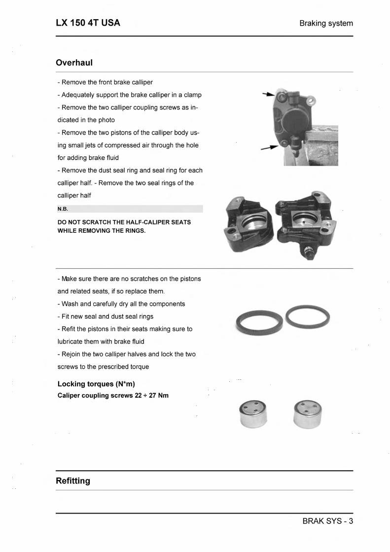
LX 150 4T USA Braking system
Overhaul
- Remove the front brake calliper
-Adequately support the brake calliper in a clamp
- Remove the two calliper coupling screws as in-
dicated in the photo
- Remove the two pistons of the calliper body us-
ing small jets of compressed air through the hole
for adding brake fluid
- Remove the dust seal ring and seal ring for each
calliper half. - Remove the two seal rings of the
calliper half
N.B.
DO NOT SCRATCH THE HALF-CALIPER SEATS WHILE REMOVING THE RINGS.
- Make sure there are no scratches on the pistons
and related seats, if so replace them.
-Wash and carefully dry all the components
- Fit new seal and dust seal rings
- Refit the pistons in their seats making sure to
lubricate them with brake fluid
- Rejoin the two calliper halves and lock the two
screws to the prescribed torque
Locking torques (N*m)
Caliper coupling screws 22 + 27 Nm
Refitting
BRAK SYS - 3

Braking system LX 150 4T USA
- lnsert the brake pads in the calliper
- lnsert the pad set pin and spring making sure to
position the end of it towards the bleed screw as
indicated in the photo.
- lnsert the stop of the brake pad pin.
N.B.
A WRONG POSITIONING OF THE PADS ACCORD- ING TO THE DIRECTION OF ROTATION CAN IM- PAIR THE BRAKE PERFORMANCE AND NOISE- LESSNESS.
Keeping the pads in contact with the pistons in-
sert the calliper in the brake disc.
- Secure the calliper to the fork using the two
screws with plastic washer to the prescribed
torque as indicated in the photo
- Secure the brake hose coupling to the calliper and tighten to the prescribed torque.
- Bleed the system and refit the front wheel
Locking torques (N*m)
Brake caliper support fixing screws 20 + 25 Nm Brake pipe union: 20+25 N*m
BRAK SYS - 4

LX 150 4T USA Braking system
Front brake disc
Removal
I y A - Remove the front wheel n - y - Remove the front brake calliper
- Remove the hub with the disc using the wheel 7
axle nut 4
-Adequately support the hub with the disc and
use the five screws shown in the photo to remove
the brake disc •
Refitting
- Carry out the operations in the reverse order
from disassembly making sure to respect the ro-
tation direction of the disc indicated by an arrow
on the disc
- Lock the 5 screws to the prescribed torque
Locking torques (N*m)
Brake disc screws: 6 +0,5 -1 Nm
Disc Inspection
- Remove the front wheel
- Using a micrometer, check the disc thickness as
shown in the figure.
BRAK SYS - 5

Braking system LX 150 4T USA
- Repeat the measurement in at least 6 points of
the disc
- Remove the front brake caliper
- To fix the specific tool, use a metal plate with
threaded hole M8 and secure it to one of the two
front brake caliper couplings
- Place the comparator on the disc outside edge
- Turn the wheel hub and check the disc deviation
Specific tooling
020335Y Magnetic stand and comparator
Characteristic
Standard thickness:
4 +0,2 -0,2mm
Max admissible deviation:
Front brake pads
Removal
- Remove the front wheel
- Remove the brake calliper
- Remove the protection cover, the pin and leaf
spring
- Extract the pads
- Check for any faults or deformation. If there is
any replace them
- Make sure the friction material thickness is
greater than 1,5mm. If not replace it
- In addition the replacement must be made if
there are remaining greater thicknesses when the
pad has not worn uniformly. A difference in re-
maining friction material thickness of 0.5 mm is al-
lowed.
BRAK SYS - 6

LX 150 4T USA Braking system
Refitting
- Insert the brake pads f i - lnsert the set pin making sure to position the clip
with the ends of it towards the bleed screw as in- gm\
dicated in the photo.
- lnsert the stop of the brake pad pin and then the
protection cover
- Secure the front brake calliper to the bracket
and lock the 2 screws to the prescribed torque. v
CAUTION
i BEFORE USING THE BRAKE, PULL THE LEVER FOR A FEW TIMES.
Locking torques (N*m)
Rear brake caliper fastening screws 20 + 25 Nm
Fill
Front
- Remove the rubber cap from the bleed screw.
- lnsert a rubber tube in the bleed screw to recov-
er the brake fluid.
- Use the right brake lever to load and pressurize
the system.
- Keeping the right lever pulled loosen the bleed
screw to let the air out of the system. Then tighten
the bleed screw
- Release the brake lever
- Repeat the operation until only brake fluid comes out of the rubber tube.
- Remove the tube and put the rubber cap from the bleed screw back on.
- Top up the level of the brake fluid in the reservoir. If necessary bleeding can be carried out using a
BRAK SYS - 7

Braking system LX 150 4T USA
specific vacuum pump
N.B.
DURING THE BLEED PROCEDURE, CHECK THE FLUID LEVEL IN THE MASTER CYLINDER RESERVOIR FREQUENTLY TO PREVENT THE RISK OF AIR ENTERING THE CIRCUIT THROUGH THE MASTER CYL- INDER.
N.B.
DURING BLEEDING, AVOID ANY CONTACT BETWEEN THE BRAKE FLUID AND THE BODY TO PRE- VENT DAMAGES. ALSO, WHILE BLEEDING THE BRAKE CALIPER AVOID ANY CONTACT BETWEEN THE FLUID AND THE BRAKE DISCS OR PADS. FAILURE TO OBSERVE THIS PRECAUTION AFFECTS THE BRAKING SYSTEM PERFORMANCE.
Specific tooling
020329Y Pump MITYVAC
Locking torques (N*m)
System bleed caliper union: 20 + 25 Nm
Brake fluid level check
Proceed as follows:
- Rest the vehicle onto its centre-stand and align m-- the handlebars; I - Check the liquid level through the inspection
hole <(A)).
A certain decrease in the liquid level is due to the
wear of the pads. I
Front brake pump
- After removing the front and rear handlebar cover remove the two U clamp fixing screws (see fig-
u re).
- Disconnect the brake tube and allow the brake fluid to flow into a receptacle.
-When refitting, follow the operations in the re-
verse order.
- Tighten the hose to the prescribed torque and
bleed the system.
Locking torques (N*m)
Oil pump-hose joint 16+20 N-m
BRAK SYS - 8

LX 150 4T USA Braking system
Removal
- Remove the front and rear handlebar cover
- Remove the two screws securing the brake
pump to the handlebars as shown in the photo
- Remove the oil hose coupling from the pump
- Remove the brake light switch connector
Overhaul
Proceed as follows:
1) remove the brake lever releasing the fixing screw; open the cover (2) and recover the membrane
(3);
2) unscrew the cap (4) and extract the internal components in a sequence;
3) check that:
- the pump body exhibits no internal scratches or corrosion;
- the piston exhibits no abnormal wear or scratches;
the piston return spring is in good working order.
BRAK SYS - 9

Braking system LX 150 4T USA
CAUTION
ANY TIME THE PUMP IS OVERHAULED, ALL SEALING COMPONENTS MUST BE REPLACED.
1. Tank cap screw.
2. Tank cap.
3. Membrane.
4. Bellows.
5. Sealing ring.
6. Piston.
7. Gasket.
8. Spring.
9. Tank
Refitting
For re-assembly, perform the operations for removal in the reverse order according to the tightening
torques.
Locking torques (N*m)
Oil piping union to pump: 20+25 Screws fixing the brake pump to the handlebar: 7 + 10 Nm
Rear drum brake
BRAK SYS - 10

LX 150 4T USA Braking system
After removing the muffler and wheel proceed as
follows:
1 .Remove the shoe spring using the specific pli-
ers.
2.Remove the shoes using a lever.
3.Fit the new shoes using a mallet and hitting
lightly.
4.Hook the spring using the specific pliers.
Specific tooling
020325~ Pliers for brake-shoe springs
BRAK SYS - 11

Braking system LX 150 4T USA
BRAK SYS - 12


Chassis LX 150 4T USA
Rear handlebar cover
Remove the handlebar rear fairing after loosening
the screws as shown in the figure.
Instrument panel
To replace the instrument panel, loosen the 4
screws shown in the figure.
Front handlebar cover
- ' Y t 17'""r-=v' Remove the 2 screws in the handlebar fairing - -7F-,
l
and the screw under the headlight.
Pull up to release the handlebar fairing and dis-
connect the headlight connections - -
CHAS - 2

LX 150 4T USA Chassis
Headlight assy.
After removing the front handlebar cover, remove
the 4 screws shown in the figure and remove the
headlight.
- Loosen the two screws located under the front
grille (see figure).
- Open the glove compartment door and remove
the three screws located inside (see figure). a9
CHAS - 3

Chassis LX 150 4T USA
Footrest
- Loosen the three screws shown in the figure
after removing the glove compartment and the
side fairings.
Air filter
- Remove the helmet bay. L - After removing the side fairing, loosen the 2
screws shown in the figure and fixing the air-box
to the engine.
- Remove the two clamps shown in the figure.
Front mudguard
- To remove the front mudguard, remove the
steering tube and release the front brake piping
from the caliper
- Then, remove the three attachments fixing the
mudguard to the steering tube as shown in the
CHAS - 4

LX 150 4T USA Chassis
figure
Front central cover
- Remove the <<PIAGGIO>> logo
- Release the screw shown in the figure
- Remove the radiator grill
CHAS - 5

Chassis LX 150 4T USA
CHAS - 6


Pre-delivery LX 150 4T USA
Aesthetic inspection
Predelivery checks:
- Paintwork
- Mating of plastics
- Scratches
- Dirt
Tightening torques inspection
Locks Inspection
- Safety locks
- Fixing screws
Safety locks:
Rear shock absorber top tightening
Rear shock absorber bottom tightening
Front wheel axle nut
Wheel hub nut
Oscillating arm pin - Chassis
Oscillating arm pin - Engine
Chassis arm-engine arm pin
Handlebar locking nut
Steering wheel lower ring nut
Steering wheel upper ring nut
Electrical system
Electrical system:
- Main switch
- Headlight: high-beam, low-beam, sidelight, and relevant warning lights
- Headlight adjustment as per statutory regulations
- Taillight, stop light
- Front and rear stop light switches
PRE DE - 2

LX 150 4T USA Pre-delivery
- Turn signals and relevant warning lights
- Dashboard light
- Gauges: fuel gauge
- Dashboard warning lights
- Horn
- Choke
CAUTION
TO ENSURE MAXIMUM PERFORMANCE, THE BATTERY MUST BE CHARGED BEFORE USE. INAD-
EQUATE CHARGING OF THE BATTERY BEFORE IT IS FIRST USED WlTH A LOW L E V L OF THE ELEC- TROLYTE SHORTENS THE LIFE OF THE BATTERY.
WARNING
BEFORE RECHARGING THE BATTERY, REMOVE THE PLUGS OF EACH ELEMENT. KEEP SPARKS AND FREE FLAMES AWAY FROM THE BATTERY WHILE RECHARGING. REMOVE THE BATTERY FROM THE VEHICLE DISCONNECTING THE NEGATIVE TERMINAL FIRST.
CAUTION
WHEN INSTALLING THE BATTERY, FIRST FIX THE POSITIVE CABLE AND THEN THE NEGATIVE CABLE.
WARNING
THE BATTERY ELECTROLYTE IS POISONOUS AND CAUSES SEVERE BURNS AS IT CON- TAINS SULPHURIC ACID. AVOID CONTACT WlTH THE EYES, THE SKIN AND CLOTHING. IN CASE OF CONTACT WlTH THE EYES OR THE SKIN, RINSE GENEROUSLY WlTH WATER FOR ABOUT 15 MINUTES AND IMMEDIATELY SEEK MEDICAL ATTENTION. IN CASE OF INGESTION, IMMEDIATEY DRINK LARGE QUANTITIES OF WATER OR VEGET- ABLE OIL. IMMEDIATELY SEEK MEDICAL ATTENTION. BATTERIES PRODUCE EXPLOSIVE GASES. KEEP THEM AWAY FROM OPEN FLAMES, SPARKS AND CIGARETTES. IF THE BATTERY IS CHARGED IN A CLOSED PLACE, TAKE CARE TO ENSURE ADEQUATE VENTILATION. ALWAYS PROTECT THE EYES WHEN WORK- ING CLOSE TO BATTERIES. KEEP OUT OF REACH OF CHILDREN
CAUTION
NEVER USE FUSES HAVING A HIGHER RATING THAN RECOMMENDED. USING A FUSE OF UNSUIT-
ABLE RATING MAY SERIOUSLY DAMAGE THE VEHICLE OR EVEN CAUSE A FIRE.
Levels check
Check the following levels:
- Hydraulic brake system fluid.
- Rear hub oil
- Engine oil
PRE DE - 3

Pre-delivery LX 150 4T USA
Road test
Road test:
- Cold starting
- Operation of instruments
- Operation of throttle control
- Stability during acceleration and braking
- Operation of front and rear brakes
- Operation of front and rear suspensions
- Abnormal noise from vehicle
Static test
Static inspection after test on the road:
- Hot start
- Starter operation
- ldel speed hold (by turning the handlebar)
- Even steering wheel rotation
- Leaks, if any
CAUTION
CHECK THE INFLATING PRESSURES WHEN THE TYRES ARE AT AMBIENT TEMPERATURE.
CAUTION
NOT EXCEED THE RECOMMENDED INFLATING PRESSURES AS THE TYRES MAY BURST.
Functional inspection
Functional Check:
Braking system (hydraulic)
- Lever stroke
Braking system (mechanical)
- Lever stroke
Clutch
- Proper performance check
Engine
- Gas control stroke check Miscellaneous
- Document check
- Check of chassis no. and engine no.
PRE DE - 4

LX 150 4T USA Pre-delivery
- Ancillary tools
- Plate assembly
- Check of locks
- Tyre pressure check
- Installation of rear-view mirrors and optional fixtures
PRE DE - 5
Pre-delivery LX 150 4T USA
PRE DE - 6


Time LX 150 4T USA
Engine
Code
ENGINE
Action Duration
Engine to frame - Disas- sembly and reassembly
Crankcase
TIME - 2

LX 150 4T USA Time
Code
CRANKCASE
Action Duration
1 001 133 Engine crankcase - Replace- ment
2 001 153 Half crankcase gasket - Re- placement
002031 Rear wheel hub bearings - Replacement
Crankshaft
Code
DRIVING SHAFT
Action Duration
1 001 117 Driving shaft - Replacement
Oil seal, flywheel side - Re- placement
Cylinder assy.
TIME - 3

Time LX 150 4T USA
Code
PISTON CYLINDER
Action Duration
Piston cylinder - Replace- ment
Cylinder, piston - Overhaul1 Cleaning
Cylinder head assy.
TIME - 4

LX 150 4T USA Time
Code
HEAD
Action Duration
1 001 045 Valves - Replacement
2 001 056 Head gasket - Replacement
3 001 126 Head - Replacement
Rocker arms support assy.
ROCKER ARMS SUPPORT ASSY.
Code Action Duration
1 001 044 Camshaft - Replacement
2 001 148 Valve rockers - Replacement
3 001 049 Valves - Adjustment
Cylinder head cover
TIME - 5

Time LX 150 4T USA
Code
HEAD COVER
Action Duration
1 001 089 Head cover - Replacement
2 001 088 Head cover gasket - Re- placement
3 001 159 Oil vapours recovery bowl - Overhaul
4 001 093 Spark plug - Replacement
5 001 097 Cooling case - Replacement
6 001091 Head cover oil seal ring
001 074 Oil vapour recovery pipe - Replacement
Chain tensioner
TIME - 6

LX 150 4T USA Time
CHAIN TIGHTENER
Code Action Duration
001 129 Chain tightener - Replace- ment
001 124 Lubrication by pass - Re- placement
Oil filter
TIME - 7

Time LX 150 4T USA
Code
OIL FILTER
Action Duration
1 001 123 Oil filter - Replacement
2 001 160 Oil pressure sensor - Re- placement
3 003064 Engine oil - Replacement
4 001 102 Oil net-filter - Replacement / Cleaning
Flywheel cover
Code
FLYWHEEL COVER
Action Duration
Flywheel cover - Replace- ment
Secondary air-exhaust mani- fold - Replacement
Secondary air filter- Replace- ment / Cleaning
4 001 174 SAS valve - Replacement
Secondary air-crankcase manifold - Replacement
Driven pulley
TIME - 8

LX 150 4T USA Time
DRIVEN PULLEY - CLUTCH
Code Action Duration
Clutch bell housing - Re- placement
2 001 022 Clutch - Replacement
3 001012 Driven pulley - Overhaul
4 001 110 Driven pulley - Replacement
Oil pump
TIME - 9

Time LX 150 4T USA
Code
OIL PUMP
Action Duration
BeltITiming chain - Replace- ment
Chain guide pads - Replace- ment
3 001 042 Oil pump - Overhaul
4 001 112 Oil pump - Replacement
5 001 130 Oil sump - Replacement
Oil seal clutch side - Re- placement
Oil pump chain - Replace- ment
Final gear assy.
TIME - 10

LX 150 4T USA Time
Code
REDUCTION GEAR
Action Duration
1 004 125 Rear wheel axle - Replace- ment
2 001 156 Geared reduction unit cover - Replacement
3 003065 Gearcase oil - Replacement
4 001 01 0 Reduction gear - Overhaul
Driving pulley
TIME - 11

Time LX 150 4T USA
Code
DRIVING PULLEY
Action Duration
Driving pulley - Disassembly and reassembly
Driving half pulley - Replace- ment
Variator rollers 1 slides - Re- placement
4 00101 1 Driving belt - Replacement
Transmission cover
TIME - 12

LX 150 4T USA Time
Code
TRANSMISSION COVER
Action Duration
Transmission casing cover - Replacement
Transmission cover bearing - Replacement
Internal transmission cover - Removal and refitting
Starter motor
TIME - 13

Time LX 150 4T USA
ELECTRIC START
Code Action Duration
Starter engine - Replace- ment
Starting motor cables - Re- placement
3 001017 Starter pinion - Replacement
4 001021 Kick starter - Overhaul
Starting sector spring - Re- placement
6 001 084 Starting lever - Replacement
Flywheel magneto
TIME - 14

LX 150 4T USA Time
Code
FLYWHEEL - FAN
Action Duration
1 001 109 Cooling fan - Replacement
2 001 173 Rotor - Replacement
Stator - Disassembly and re- assembly
4 001 058 Flywheel - Replacement
Belt cooling duct
TIME - 15

Time LX 150 4T USA
Code
BELT COOLING PIPE
Action Duration
Cooling air duct - Replace- ment
Transmission air intake tube - Replacement
Transmission air inlet - Re- placement
Carburettor
TIME - 16

LX 150 4T USA Time
Code
CARBURETTOR
Action
_/ - . _ -- cry
Duration
Carburettor heating resistor - Replacement
2 001 01 3 Intake hose - Replacement
Carburettor-filter bellow - Re- placement
Automatic starter device - Replacement
5 001 008 Carburettor - Overhaul
6 001 063 Carburettor - Replacement
Exhaust pipe
TIME - 17

Time LX 150 4T USA
Code
MUFFLER
Action Duration
1 001 009 Exhaust pipe - Replacement
Exhaust emissions - Adjust- ment
Silencer guard - Replace- ment
Air cleaner
TIME - 18

LX 150 4T USA Time
Code
AIR FILTER
Action Duration
Carburettor filter manifold - Replacement
Air Filter - ReplacementlClean- ing
3 001 01 5 Air filter box - Replacement
Frame
TIME - 19

Time LX 150 4T USA
Code
CHASSIS
Action Duration
1 004001 Chassis - Replacement
Front shield beading - Re- placement
Front shield cover - Replace- ment
Plates 1 Stickers - Replace- ment
5 0040 12 Posterior flanks - Substitution
004059 Spark plug inspection flap - Replacement
TIME - 20
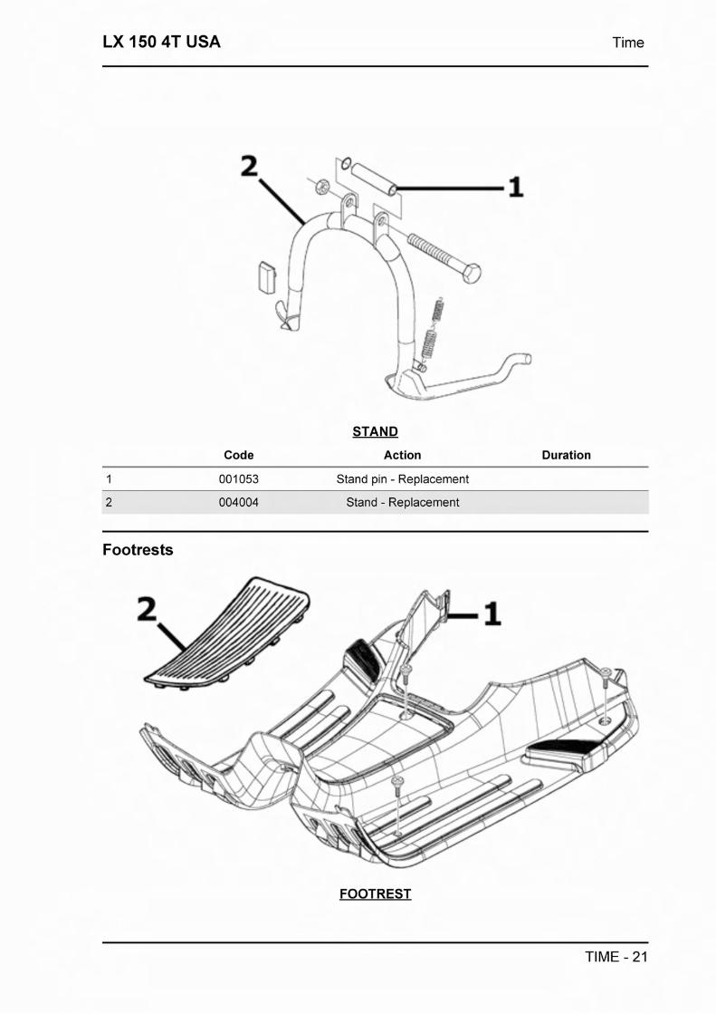
LX 150 4T USA Time
STAND
Code Action Duration
1 001 053 Stand pin - Replacement
2 004004 Stand - Replacement
Footrests
FOOTREST
TIME - 21

Time LX 150 4T USA
Code Action Duration
1 0041 78 Footrest - Replacement
004078 Frontlrear footboard rubber. - Replacement
Rear cover
Code
KNEE-GUARD
Action Duration
Glove-box remote opening linkage - Replacement
Knee-guard - Removal and refitting
Glove comparment door - Replacement
4 004082 Trunk gasket - Replacement
Underseat compartment
TIME - 22

LX 150 4T USA Time
UNDERSEAT COMPARTMENT
Code Action Duration
1 005046 Battery cover - Replacement
Helmet compartment - Disas- sembly and reass
3 001 027 Filter bellow - Replacement
TIME - 23

Time LX 150 4T USA
Code
UNDERSEAT
Action Duration
Helmet compartment - Re- placement
2 005046 Battery cover - Replacement
Chassis central cover - Re- placement
Battery compartment - Re- placement
Plate holder
TIME - 24
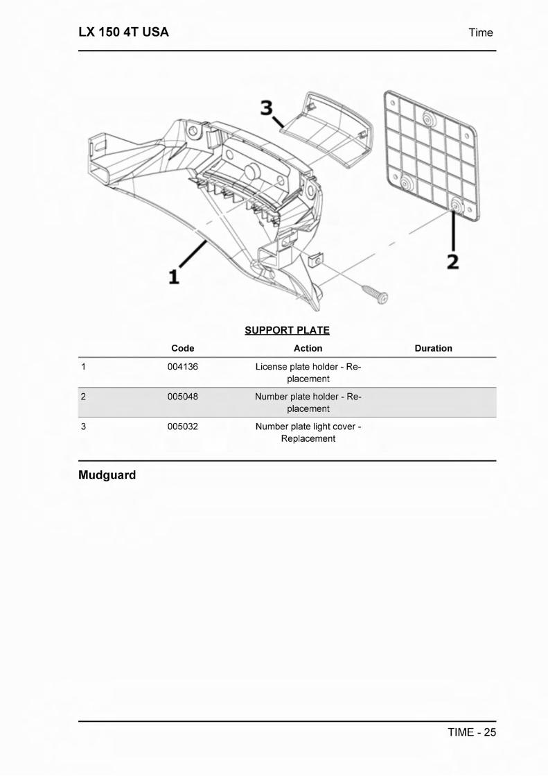
LX 150 4T USA Time
Code
SUPPORT PLATE
Action Duration
License plate holder - Re- placement
Number plate holder - Re- placement
Number plate light cover - Replacement
Mudguard
TIME - 25

Time LX 150 4T USA
Code
MUDGUARDS
Action Duration
Front mudguard - Replace- ment
Rear mudguard - Replace- ment
Fuel tank
TIME - 26

LX 150 4T USA Time
FUEL TANK
Code Action Duration
1 004 168 Fuel filler cap - Replacement
2 00501 0 Tank float - Replacement
3 0041 12 Cock-carburettor pipe - Re- placement
4 004005 Fuel tank - Replacement
5 004007 Mixture cock - Replacement
004 1 09 Fuel tank breather - Replace- ment
Rear shock-absorber
TIME - 27

Time LX 150 4T USA
REAR SHOCK ABSORBER
Code Action Duration
Rear shock absorber - Disas- sembly and reassembly
Steering column bearings
I -- -
STEERING COLUMN BEARINGS
TIME - 28

LX 150 4T USA Time
Code Action Duration
1 003002 Steering fifth wheels - Re- placement
2 003073 Steering play - Adjustment
3 0041 19 Bearing / Upper steering bearing - Replacement
Handlebar covers
SPEEDOMETER - HANDLEBAR COVERS
Code Action Duration
00401 8 Handlebar front part - Re- placement
Handlebar rear part - Re- placement
3 005054 Speedometer - Replacement
4 005038 Dashboard warning lights - Replacement
5 005078 Odometer plastic cover - Re- placement
TIME - 29

Time LX 150 4T USA
Handlebar components P%
HANDLEBAR COMPONENTS
Code Action Duration
Rearview mirrors - Replace- ment
Complete gas control - Re- placement
3 002071 Left knob - Replacement
Handlebar - Disassembly and reassembly
Stop light switch - Replace- ment
002024 Brake pump - Removal and reinstallation
7 003061 Accelerator transmission - Adjustment
8 002060 Complete gas control - Re- placement
0041 62 Mirror U-bolt and/or brake pump fitting - Replacement
10 002059 Right knob - Replacement
Gas control transmission - Replacement
TIME - 30

LX 150 4T USA Time
Code
SWINGING ARM
Action Duration
Engine-frame connection swing arm - Replacement
Seat
TIME - 31

Time LX 150 4T USA
Code
SADDLE
Action Duration
1 004003 Saddle - Replacement
004131 Rear rack mounting bracket - Replacement
Turn signal lights
Code
TURN SIGNAL LIGHTS
Action Duration
1 005002 Headlight - Replacement
Front turn signal light - Re- placement
Front direction indicator bulb - Replacement
Front headlights - Replace- ment
5 005005 Rear light - Replacement
Rear light bulbs - Replace- ment
Rear turn signal light - Re- placement
005068 Rear turn indicator bulb - Re- placement
TIME - 32

LX 150 4T USA Time
Front wheel
FRONT WHEEL
Code Action Duration
1 004 123 Front wheel - Replacement
003047 Front tyre - Replacement
Front wheel rim - Replace- ment
Front wheel hub - Replace- ment
5 002041 Brake disc - Replacement
Front wheel hub bearings - Replacement
Rear wheel
TIME - 33

Time LX 150 4T USA
Code
REAR WHEEL
Action Duration
1 004126 Rear tyre - Replacement
Rear wheel rim - Removal and refitting
3 001016 Rear wheel - Replacement
Rear brake shoeslpads - Re- placement
Electric
ELECTRIC COMPONENTS
TIME - 34

LX 150 4T USA Time
Code Action Duration
1 005001 Electric circuit - Replacement
2 00501 1 Start-up remote control switch - Replacement
3 005009 Voltage regulator - Replace- ment
4 005007 Battery - Replacement
5 005052 Fuse ( I ) - Replacement
6 001 023 Controller - Replacement
001 094 Spark plug cap - Replace- ment
8 001 069 H.T. coil - Replacement
Electronic controls
Code
ELECTRIC CONTROLS
Action Duration
1 005039 Light switch - Replacement
Lights or flashlights switch - Replacement
3 005040 Horn button - Replacement
4 005003 Electric horn - Replacement
5 005041 Starter button - Replacement
6 00501 6 Key switch - Replacement
TIME - 35

Time LX 150 4T USA
Code Action Duration
7 004096 Locks series - Replacement
8 0040 10 Antitheft lock - Replacement
Transmissions
TRANSMISSIONS
Code Action Duration
002053 Rear brake transmissions as- sembly - Replacement
Odometer transmissions as- sembly - Replacement
Odometer cable - Replace- ment
Front suspension
TIME - 36

LX 150 4T USA Time
FRONT SUSPENSION
Code Action Duration
Steering column - Replace- ment
2 00301 0 Front suspension - - Revision
Shock abs. and brake caliper support - Replacement
Speedometer gear - Re- placement
003044 Shock absorber cover - Re- placement
Braking system
TIME - 37

Time LX 150 4T USA
Code
BRAKING SYSTEM
Action Duration
Front brake line - Replace- ment
Front brake shoeslpads - Re- moval and refitting
Front brake calliper - Remov- al and refitting
Front brake liquid and circuit bleeding - Replacement
002002 Rear brake shoe - pad - Re- placement
Secondary air box
TIME - 38

LX 150 4T USA Time
v . - . 1
.. . .. . . ' .dr-- - - - - . , . . 8, ,. .- .&-::4p4\ ;:; : - -.. , .+- I .-
>- x i I l l - *. . -*-
' L - 1 t .Ll .; /
I . . n' -
Code
SISTEMA ARIA SECONDARIA
Action
P9 ,. .
Duration
Crankcase secondary air junction - Replacement
Secondary air filter- Replace- ment 1 Cleaning
3 001 174 SAS valve - Replacement
Exhaust secondary air junc- tion - Replacement
TIME - 39