Manual for Carving Machine - Toolots
112
Manual for Carving Machine
-
Upload
khangminh22 -
Category
Documents
-
view
0 -
download
0
Transcript of Manual for Carving Machine - Toolots
Manual for CarvingMachine
ContentsHome Page.................................................................................................................................................3
Notes before Installation............................................................................................................................4
Chapter 1 Composition of Carving Machine.............................................................................................6
1.Picture................................................................................................................................................6
2.Accessories of carving machine..................................................................................................... 12
Chapter 2 Installation and Software Setting of Carving Machine........................................................... 13
1.Machine installation....................................................................................................................... 13
2.Software installation.......................................................................................................................14
3. Parameter setting of DSP hand shank......................................................................................... 14
Chapter 3 Operation Flow of the Carving Machine................................................................................ 17
Chapter 4 Selection of Cutter...................................................................................................................19
Chapter 5 Daily Maintenance of the Machine......................................................................................... 21
Chapter 6 Fault and Analysis................................................................................................................... 23
Appendix Instruction for DSP Hand Shank.............................................................................................27

- 3 -
Home Page
Thank you for choosing our products. Please read this instructions
carefully before installation so as to avoid the unnecessary troubles for
your installation and use.

- 4 -
Notes before Installation
1. Do not install this device in lightning and thunder. Do not install
electric outlet in damp places. Do not touch un-insulated power lines.
2.Operators must be strictly trained before operation and pay attention to
personal security and machine safety in operation.
3. The power supply voltage is required to be 210V~230V. Please install
voltage-stabilizing current with the guidance of professionals for the
unstable power supply voltage or power consumption equipment with
high power.
4.Do not plug in or plug out the data cable in electrification. The machine
and the control cabinet should be connected to the ground.
5.Operators are prohibited to wear gloves and they had better wear
protection glasses.
6. Cutting tools must be clamped to keep sharp. The dull cutting tools will
reduce the quality of carving and cause the motor overload.
7. Do not put your hand into the work scope of cutting tools. Do not
process materials containing asbestine.
- 5 -
8. Processing material size should be within the scope of machining
operation. Please cut off the power supply if it is not used for long time.
Professionals must guide the machine moving.
9.There must be water supply of the water-cooling spindle before use.
10.Please contact the distributor or after-sales service department for any
fault of the machine.
- 6 -
Chapter 1 Composition of Carving Machine
1.Picture
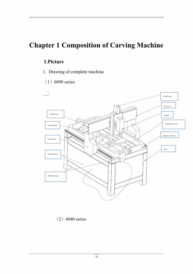
1. Drawing of complete machine
(1)6090 series
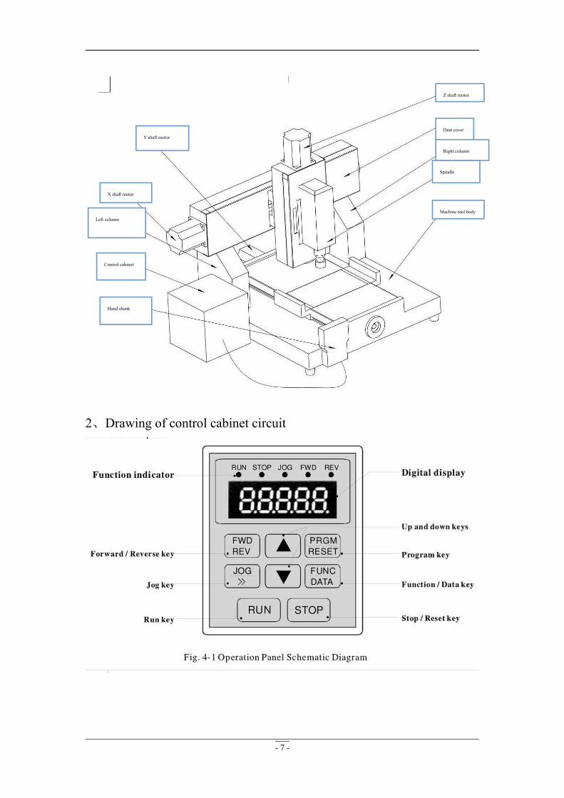
(2)4040 series
Y-shaft motor
X- shaft motor
Left column
Control cabinet
Z shaft motor
Dust cover
Spindle
Y shaft guide screw
Machine tool body
Base
DSP hand shank
- 7 -
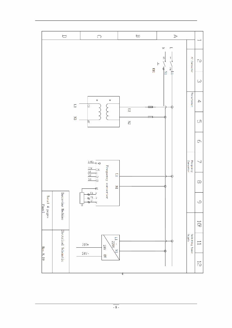
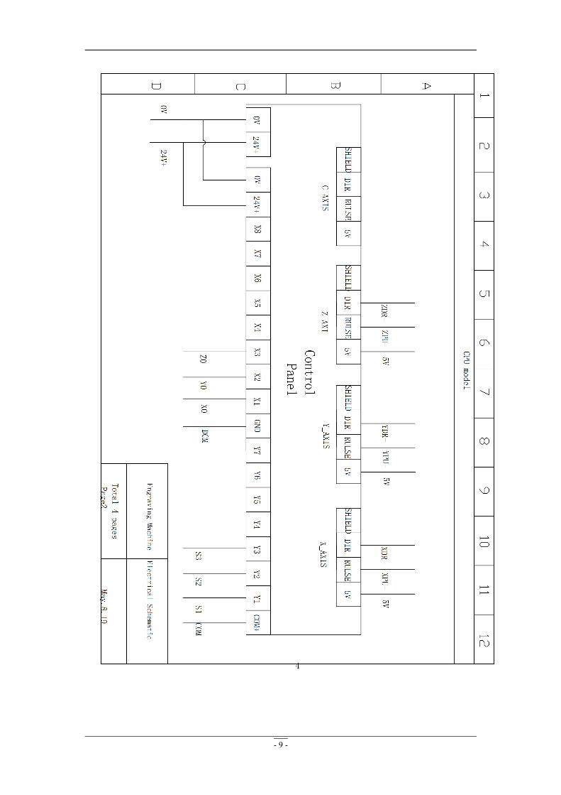
2、Drawing of control cabinet circuit
Y shaft motor
X shaft motor
Left column
Control cabinet
Hand shank
Z shaft motor
Dust cover
Right column
Spindle
Machine tool body
- 8 -
- 9 -
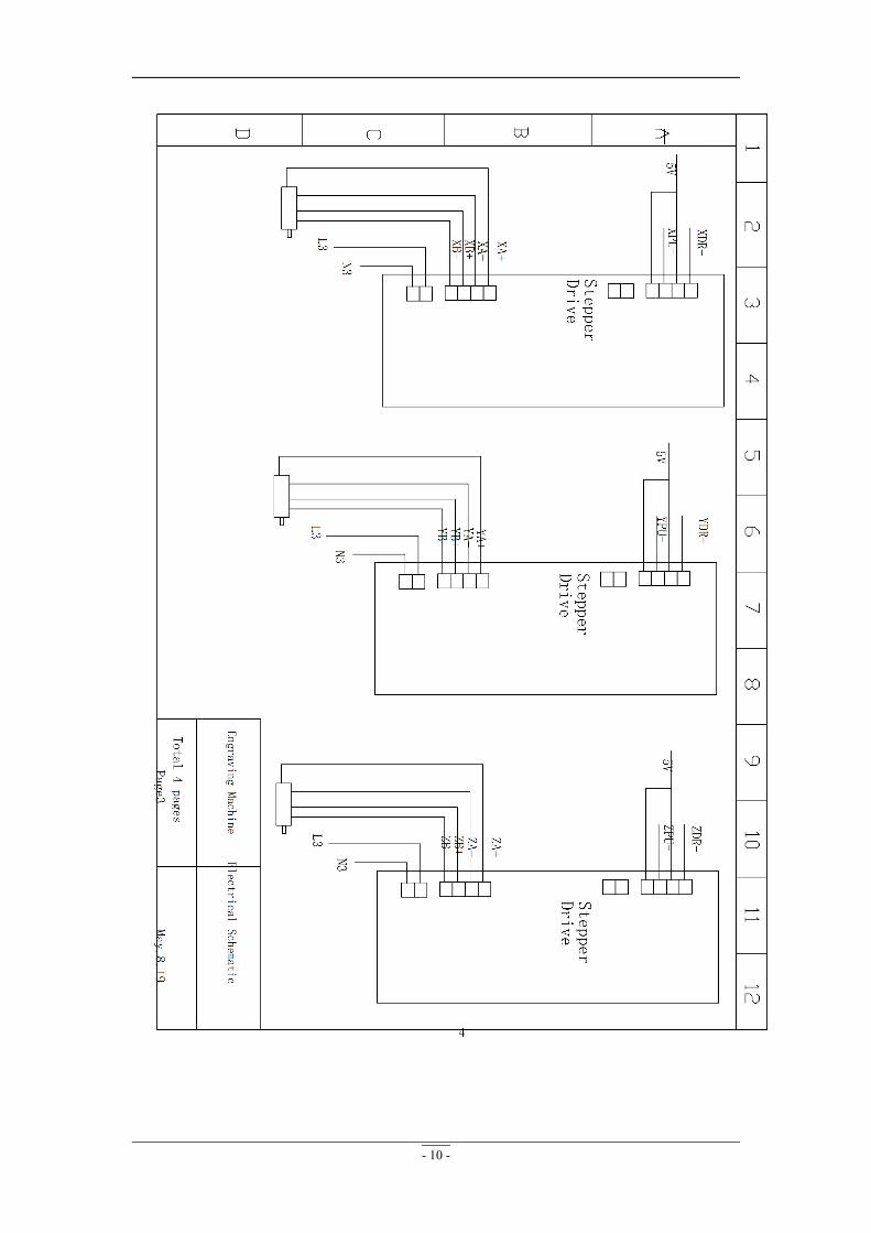
- 10 -
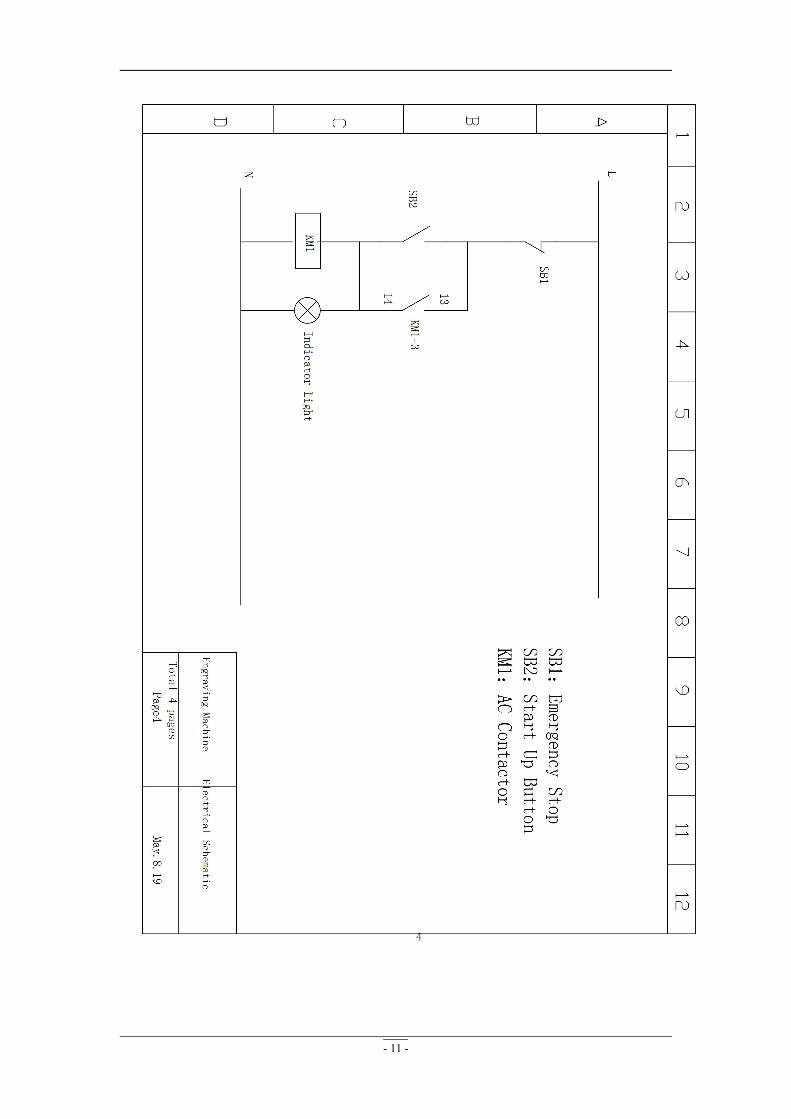
- 11 -

- 12 -
4. Frequency converter panel indicator diagram
2. Accessories of carving machine
Name Remarks
Power line 1
Water pump (Air-cooled spindle is
not configured with this accessory.)
1
Tool case 1
Crving tool 1
DSP hand shank 1
Instruction 1
Platen 6
Spanner 1
Cutter holder 1
- 13 -
Chapter 2 Installation and Software
Setting of Carving Machine
1.Machine installation
Warning: All operations must be performed in power
failure.
1. Open the wooden case to lift out the machine and place it
on the ground. Please hand shank slightly to avoid collision.
2. Open the tool case to check if all the accessories are
complete according to the packing list.
3. Please connect the control cable to DSP hand shank or
control card.(Please turn on the computer case and insert
the control card to computer PCI slot if the machine is
controlled by NC studio.)
4. Connect the water pump water outlet to spindle motor water
pipe and place the water pump into the water tank. The
water tank is filled with two-thirds water. It is better to use
purified water for the protection of the spindle(This
procedure can be skipped for air cooling spindle.)
5. Insert one end of the power line into the power interface of
the control cabinet and the other end into the standard 220V

- 14 -
electric outlet(Please check the different voltage used in
different countries for the imported machines.).
6. Please load different gravers according to different carving
materials (Please refer to Chapter 4 for the selection of
gravers.)
2.Software installation
1. Installation of typesetting software
Customers choose different installation methods for different
software(Please refer to the instruction for TYPE3 for the
installation of TYPE3 and ARTCUT V8 for the installation of
V8.).
2. Installation of control software
( 1)We have set various parameters for the hand shank if the
customers’ machines are controlled by DSP hand shank before
leaving the factory. Please copy the typesetted files directly into
the hand shank.
3. Parameter setting of DSP hand shank
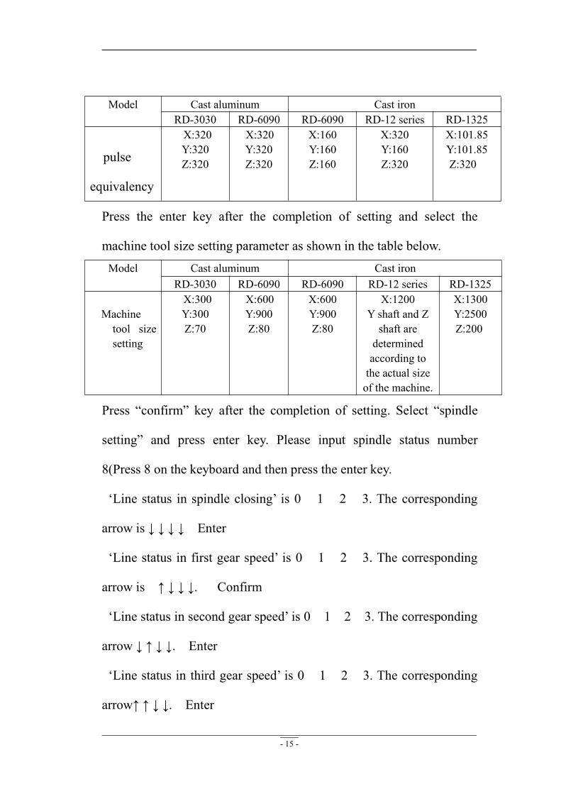
1. Press the “menu” key to enter the parameter setting. Select the
machine tool parameter configuration for confirm. Select the pulse
equivalency parameter setting as shown in the table below.
- 15 -
Model Cast aluminum Cast ironRD-3030 RD-6090 RD-6090 RD-12 series RD-1325
pulse
equivalency
X:320Y:320Z:320
X:320Y:320Z:320
X:160Y:160Z:160
X:320Y:160Z:320
X:101.85Y:101.85Z:320
Press the enter key after the completion of setting and select the
machine tool size setting parameter as shown in the table below.Model Cast aluminum Cast iron
RD-3030 RD-6090 RD-6090 RD-12 series RD-1325
Machinetool sizesetting
X:300Y:300Z:70
X:600Y:900Z:80
X:600Y:900Z:80
X:1200Y shaft and Zshaft aredeterminedaccording tothe actual sizeof the machine.
X:1300Y:2500Z:200
Press “confirm” key after the completion of setting. Select “spindle
setting” and press enter key. Please input spindle status number
8(Press 8 on the keyboard and then press the enter key.
‘Line status in spindle closing’ is 0 1 2 3. The corresponding
arrow is ↓ ↓ ↓ ↓ Enter
‘Line status in first gear speed’ is 0 1 2 3. The corresponding
arrow is ↑ ↓ ↓ ↓. Confirm
‘Line status in second gear speed’ is 0 1 2 3. The corresponding
arrow ↓ ↑ ↓ ↓. Enter
‘Line status in third gear speed’ is 0 1 2 3. The corresponding
arrow↑ ↑ ↓ ↓. Enter
- 16 -
‘Line status in fourth gear speed’ is 0 1 2 3. The corresponding
arrow ↓ ↓ ↑ ↓. Enter
‘Line status in fifth gear speed’ is 0 1 2 3. The corresponding
arrow↑ ↓ ↑ ↓. Enter
‘Line status in sixth gear speed’ is 0 1 2 3. The corresponding
arrow↓ ↑ ↑ ↓. Enter
‘Line status in seventh gear speed’ is 0 1 2 3. The
corresponding arrow ↑ ↑ ↑ ↓. Enter
Press the “enter” key after the completion of setting( Press the
X-downward arrow). Select the electrical level definition and press
enter key.
Select ‘input electrical level definition’ and press the enter key. Move
the arrow of 0 1 2 to ↑↑↑( Press ‘Y+’ for arrow upwards, ‘Y-’ for
arrow downwards and ‘X+ -’ for the movement of cursor position.)
and then press the enter key. Press “ESC” key to return to
parameter setting interface after the completion of setting.
2.Select ‘processing parameter configuration’ and press the enter key.
Select ‘linear acceleration’ and press the enter key to set it to 600
mm/s 2. Press the enter key again. Select curve acceleration and then
press the enter key to set it to 800 mm/s 2. Press the enter key again
and return to the main interface after the completion of setting.
(Please see the instruction for DSP hand shank in the appendix.)
- 17 -
Chapter 3 Operation Flow of the Carving
Machine
1. Please carry out design and typesetting, calculate the path
correctly and save files in accordance with customers’
requirements.
2. Please copy the file to DSP hand shank.(Please open the
control card software, read the typesetting and save the
files for the control card machine.)
3. Please fix the material, fix the original point, start the
spindle and adjust the rotation rate of the spindle.
4. The machine will have reset self-checking with power on
and X, Y, Z shaft return to zero point and then run to their
initial position.
5. Adjust X, Y, Z shaft aligned to the original point of the
carving. Adjust the rotation rate of the spindle, feeding
speed and height of Z shaft so as to make the carving
machine in work waiting status.
6. The machine will complete the carving work of the file
after opening the carving file and transferring files to the
carving machine.
7. The carving machine will automatically lift the cutter and

- 18 -
run to the upper place of the work starting point after the
completion of file carving.
- 19 -
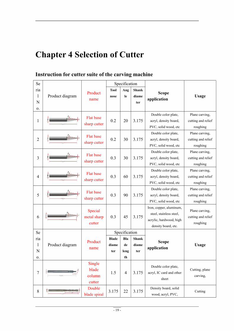
Chapter 4 Selection of Cutter
Instruction for cutter suite of the carving machineSerialNo.
Product diagramProductname
Specification
Scope ofapplication
UsageTool
nose
Ang
le
Shank
diame
ter
1Flat basesharp cutter
0.2 20 3.175Double color plate,
acryl, density board,
PVC, solid wood, etc
Plane carving,
cutting and relief
roughing
2Flat basesharp cutter
0.2 30 3.175Double color plate,
acryl, density board,
PVC, solid wood, etc
Plane carving,
cutting and relief
roughing
3Flat basesharp cutter
0.3 30 3.175Double color plate,
acryl, density board,
PVC, solid wood, etc
Plane carving,
cutting and relief
roughing
4Flat basesharp cutter
0.3 60 3.175Double color plate,
acryl, density board,
PVC, solid wood, etc
Plane carving,
cutting and relief
roughing
5Flat basesharp cutter
0.3 90 3.175Double color plate,
acryl, density board,
PVC, solid wood, etc
Plane carving,
cutting and relief
roughing
6Special
metal sharpcutter
0.3 45 3.175
Iron, copper, aluminum,
steel, stainless steel,
acrylic, hardwood, high
density board, etc.
Plane carving,
cutting and relief
roughing
SerialNo.
Product diagramProductname
Specification
Scope ofapplication
UsageBlade
diame
ter
Bla
de
leng
th
Shank
diame
ter
7
Singlebladecolumncutter
1.5 4 3.175Double color plate,
acryl, IC card and other
sheet
Cutting, plane
carving,
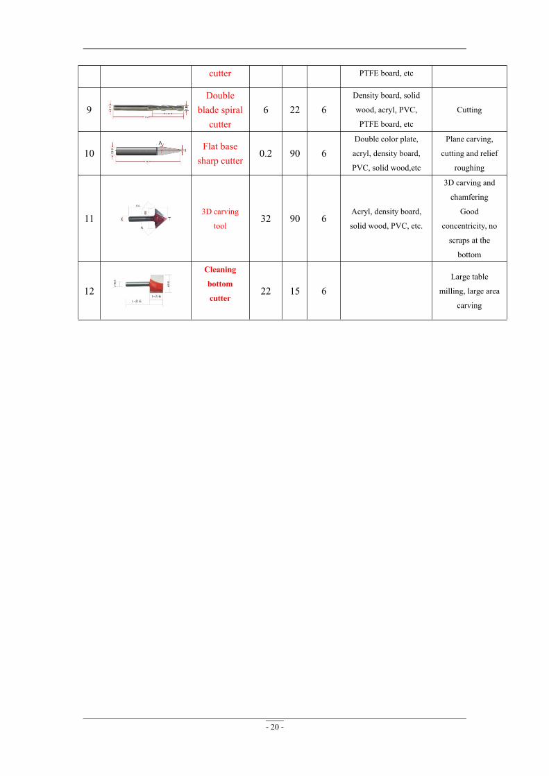
8Double
blade spiral3.175 22 3.175
Density board, solid
wood, acryl, PVC,Cutting
- 20 -
cutter PTFE board, etc
9Double
blade spiralcutter
6 22 6Density board, solid
wood, acryl, PVC,
PTFE board, etc
Cutting
10Flat basesharp cutter
0.2 90 6Double color plate,
acryl, density board,
PVC, solid wood,etc
Plane carving,
cutting and relief
roughing
113D carving
tool32 90 6
Acryl, density board,
solid wood, PVC, etc.
3D carving and
chamfering
Good
concentricity, no
scraps at the
bottom
12
Cleaning
bottom
cutter22 15 6
Large table
milling, large area
carving
- 21 -
Chapter5 DailyMaintenance of theMachine
As a kind of numerical control machine, the carving machine has a
certain requirements for power grid environment with no electric welder,
frequently started machine tool, power tool and radio station on the power
grid of the system. Intense grid interference can lead to abnormal
operation of computer and the system of the carving machine.
1. The machine should be used according to the operation
specifications in the actual use.
2. The working table should be cleaned every day after the
completion of work and the lead rail and the guide screw should
be added with lubricant after cleaning for the maintenance.
3. The machine should be maintained regularly every month.
Operators should check if the screws of various mechanical parts
are loosen so as to the lubrication and working environment of the
machine.
4. Operators need to check whether the water pipe connecting the
water pump and the spindle is smooth and check whether the water
pump flow is normal.
5. Please select the electric outlet with good ground protection in
order to avoid the product scrap in abnormal processing caused by

- 22 -
poor contact of electric outlet loosen.
The standard maintenance of the carving machine is related not only with
the precision of the carving machine but also with the life service of the
carving machine. Therefore, it is important for operators to develop good
habit so as to prolong the life service of the carving machine.
- 23 -
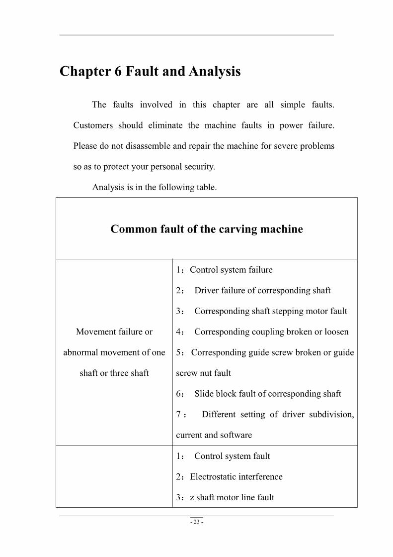
Chapter 6 Fault and Analysis
The faults involved in this chapter are all simple faults.
Customers should eliminate the machine faults in power failure.
Please do not disassemble and repair the machine for severe problems
so as to protect your personal security.
Analysis is in the following table.
Common fault of the carving machine
Movement failure or
abnormal movement of one
shaft or three shaft
1:Control system failure
2: Driver failure of corresponding shaft
3: Corresponding shaft stepping motor fault
4: Corresponding coupling broken or loosen
5:Corresponding guide screw broken or guide
screw nut fault
6: Slide block fault of corresponding shaft
7: Different setting of driver subdivision,
current and software
1: Control system fault
2:Electrostatic interference
3:z shaft motor line fault

- 24 -
Z shaft out of control 4:File path error
5:Inverter interference
6:Computer system problems or viruses
7:Operation error
Error
1: Control system fault
2: Driver fault
3: Stepping motor fault
4:Electrostatic interference
5: Motor line fault
6: Data line fault
7: Path error
8:Coupling broken or loosen
9:Rapid processing speed
10:Computer system problems or viruses
Different carving depth
1:Control system fault
2:Stepping motor fault
3 : Driver failure or current subdivision
inconsistency with software setting
4;z shaft motor line fault
5:Spindle motor fault
6: Frequency converter interference or data
setting error
- 25 -
7:Electrostatic interference
8:Computer system problems or viruses
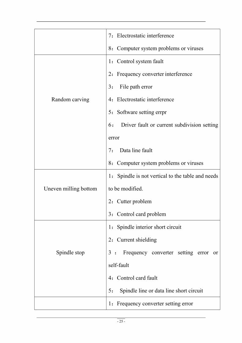
Random carving
1:Control system fault
2:Frequency converter interference
3: File path error
4:Electrostatic interference
5:Software setting errpr
6: Driver fault or current subdivision setting
error
7: Data line fault
8:Computer system problems or viruses
Uneven milling bottom
1:Spindle is not vertical to the table and needs
to be modified.
2:Cutter problem
3:Control card problem
Spindle stop
1:Spindle interior short circuit
2:Current shielding
3 : Frequency converter setting error or
self-fault
4:Control card fault
5: Spindle line or data line short circuit
1:Frequency converter setting error
- 26 -
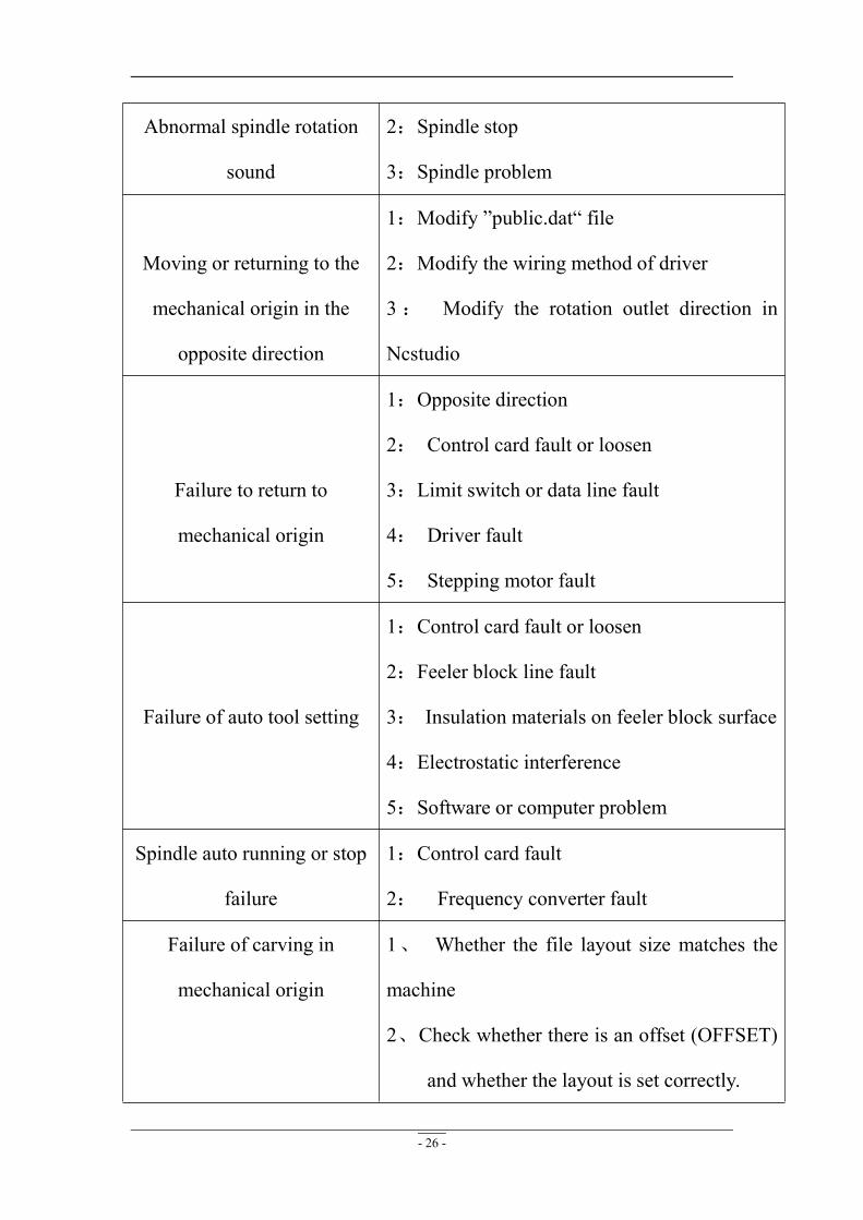
Abnormal spindle rotation
sound
2:Spindle stop
3:Spindle problem
Moving or returning to the
mechanical origin in the
opposite direction
1:Modify ”public.dat“ file
2:Modify the wiring method of driver
3: Modify the rotation outlet direction in
Ncstudio
Failure to return to
mechanical origin
1:Opposite direction
2: Control card fault or loosen
3:Limit switch or data line fault
4: Driver fault
5: Stepping motor fault
Failure of auto tool setting
1:Control card fault or loosen
2:Feeler block line fault
3: Insulation materials on feeler block surface
4:Electrostatic interference
5:Software or computer problem
Spindle auto running or stop
failure
1:Control card fault
2: Frequency converter fault
Failure of carving in
mechanical origin
1、 Whether the file layout size matches the
machine
2、Check whether there is an offset (OFFSET)
and whether the layout is set correctly.

- 27 -
Appendix Instruction for DSPHand Shank
Thank you for choosing the products!
This manual helps you be familiar with the company's products, and get information about
systems’ components,configuration,etc.
This manual detailed knowledge of the system characteristics,operational processes,
installation,commissioning, and safety precautions.Please read this manual carefully before using
the system and machine, which will help you use it better.
Cautions:
1. Use of this product is strictly prohibited in the strong interference, strong magnetic field
environment. Operating ambient temperature 0-70 ℃, working environment humidity
0-90% (non-condensing).
2. Insert U disk in the correct direction.Do not pull out 50-pin cable when system run.
3. During processing U disk file process, do not pull out the U disk to prevent the interruption
of data transmission.
4. Strictly prohibited metal, dust, and other conductive substances enter the controller.
5. The machine shell should connect the ground wire to ensure the safety of the work and to
prevent interference.
6. Prohibited unauthorized disassembly, no user-repairable parts..
7. Unused for long periods of time, please pay attention to the power outage, and keep properly.
8. Pay attention to water, dust, fire when using it.
9. Do not use the corrosive chemical solvents to clean the equipment.
10. Spindle motor bearing life and its speed is inversely proportional.
11. Graver is very sharp. Do not touch when it is running in order to avoid injury; Do not use
handkerchiefs, scarves to touch it to prevent embroiled damage.
Important Notice:
The Company shall not be responsible for any loss caused by improper using or breaking the
correct operating procedures.
Beijing RichAuto S&T co.,Ltd owns this manual final interpretation,the company reserves
the right to modify all information in this manual, including data, technical details, etc..
Contents Foreword..............................................................................................................1
1. RichAuto system composition.............................................................................3
1.1 System composition......................................................................................... 3
1.2 Description of each component........................................................................4
1.2.1 Handle...........................................................................................................4
1.2.2 Interface board.............................................................................................. 5
1.2.3 50-pin data transmission cable......................................................................5
1.2.4 USB communication cable........................................................................... 5
1.3 Interface board shell size..................................................................................6
1.4 System start-up mode....................................................................................... 6
2. Handle buttons introduction.............................................................................6
2.1 Buttons introduction.........................................................................................6
2.2 Usage mode...................................................................................................... 7
2.3 Detail information for buttons function........................................................... 8
3. Wiring Instructions.......................................................................................... 9
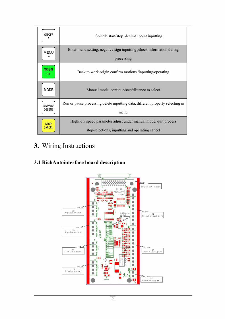
3.1 RichAuto interface board description.............................................................. 9
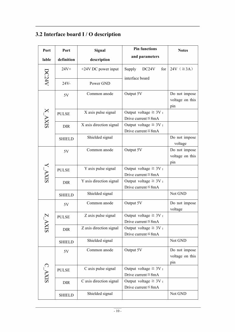
3.2 Interface board I / O description.................................................................... 10
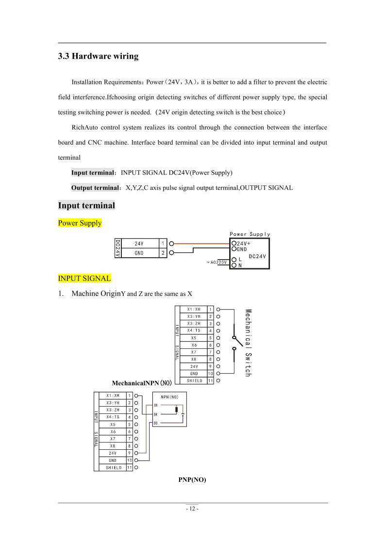
3.3 Hardware wiring.............................................................................................12
3.4 Commissioning of the machine and control system.......................................16
4. Menu Description.......................................................................................... 16
4.1 Menu category................................................................................................16
4.2 Menu details................................................................................................... 17
4.2.1 MACHINE SETUP.................................................................................... 17
4.2.2 AUTO PRO SETUP................................................................................... 20
4.2.3 SYSTEM SETUP....................................................................................... 23
4.2.4 OPERATE FILE......................................................................................... 27
4.2.5 VERSION VIEW........................................................................................28
5. Machine Operation............................................................................................ 29
5.1 Return home................................................................................................... 30
5.2 Import processing files................................................................................... 30
5.3 Manual operation............................................................................................30
5.3.1 Manual speed switching and adjusting....................................................... 30
5.3.2 Manual mode.............................................................................................. 31
5.3.3 Manual testing input and output................................................................. 32
5.3.4 Manualswitching coordinate system...........................................................33
5.4 Automatic processing operation.....................................................................34
5.4.1 Set workpiece origin................................................................................... 34
5.4.2 Choose processing file................................................................................35
5.4.3 Setprocessing parameters............................................................................35
5.5 Operations during processing.........................................................................36
5.6 Advanced Processing..................................................................................... 39
5.6.1 Array work..................................................................................................39
5.6.2 Resume work.............................................................................................. 40
5.6.3 Tool changing............................................................................................. 40
5.6.4 Part work.....................................................................................................40
5.6.5 Calculate bound.......................................................................................... 41
5.6.6 Mill plane....................................................................................................41
5.6.7 Calculate work time....................................................................................42
5.6.8 Find break no.............................................................................................. 42
5.6.9 Scale work...................................................................................................43
6. A12 Plasma Cutting Motion Control System.................................................... 44
6.1 Handle andbuttons introduction..................................................................... 44
6.2 Output description.......................................................................................... 45
6.3 Arc setup&wiring...........................................................................................45
6.4 Parameters description................................................................................... 46
7. A15--Multi-spindle Motion Control System..................................................... 47
7.1 Handle andbuttons introduction..................................................................... 48
7.2 Output description.......................................................................................... 48
7.3 Spindle wiring................................................................................................ 48
7.4 Multi-spindlesetup..........................................................................................50
7.5 G code example..............................................................................................52
8. A18--Four-axis Linkage Motion Control System..............................................52
8.1 Handle buttons introduction........................................................................... 53
8.2 Input description.............................................................................................53
8.3 Parameters description................................................................................... 53
8.4 G code example..............................................................................................54
9. Appendix............................................................................................................54
9.1 System upgrade.............................................................................................. 55
9.2 U-disk Function..............................................................................................55
9.3 Servo driver parameters................................................................................. 56
9.3.1 YASKAWA Σ-7、Σ-Ⅴ...............................................................................56
9.3.2 PANASONIC MINAS A5..........................................................................58
9.3.3 DELTAASDA-A2&B2...............................................................................60
9.4 G code list.......................................................................................................64
9.5 Tool setting(Tool measurement).....................................................................66
9.5.1 Fixed calibration......................................................................................... 66
9.5.2 Mobile calibration.......................................................................................67
9.6 Calculate pulse equivalent..............................................................................70
9.6.1 Stepper driver..............................................................................................70
9.6.2 Servo driver.................................................................................................72
9.6.3 Proportion calculation method....................................................................75
9.7 ........................................................................................................................76
9.7.1 Solutions of the faults display on the screen...............................................76
9.7.2 Faults in practical operation........................................................................77
9.7.3 Electrical components and wiring problem................................................. 80
- 1 -
Foreword
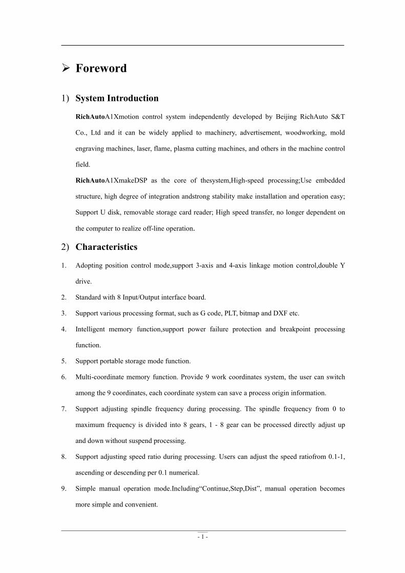
1) System Introduction
RichAutoA1Xmotion control system independently developed by Beijing RichAuto S&T
Co., Ltd and it can be widely applied to machinery, advertisement, woodworking, mold
engraving machines, laser, flame, plasma cutting machines, and others in the machine control
field.
RichAutoA1XmakeDSP as the core of thesystem,High-speed processing;Use embedded
structure, high degree of integration andstrong stability make installation and operation easy;
Support U disk, removable storage card reader; High speed transfer, no longer dependent on
the computer to realize off-line operation.
2) Characteristics
1. Adopting position control mode,support 3-axis and 4-axis linkage motion control,double Y
drive.
2. Standard with 8 Input/Output interface board.
3. Support various processing format, such as G code, PLT, bitmap and DXF etc.
4. Intelligent memory function,support power failure protection and breakpoint processing
function.
5. Support portable storage mode function.
6. Multi-coordinate memory function. Provide 9 work coordinates system, the user can switch
among the 9 coordinates, each coordinate system can save a process origin information.
7. Support adjusting spindle frequency during processing. The spindle frequency from 0 to
maximum frequency is divided into 8 gears, 1 - 8 gear can be processed directly adjust up
and down without suspend processing.
8. Support adjusting speed ratio during processing. Users can adjust the speed ratiofrom 0.1-1,
ascending or descending per 0.1 numerical.
9. Simple manual operation mode.Including“Continue,Step,Dist”, manual operation becomes
more simple and convenient.
- 2 -
10. Support M,F code and other expandedcodes,special code can be customized according to
actual request.
11. Built-in 512 Mbmemory.Communication by USB interface.
12. Unique handheld form to realizeholding by one hand.Liquid crystal display and 16
buttonsmake operating intuitive and flexible.No longer dependent on the computer to realize
off-line operation.
13. Self-testfunction,systemsupports I/O signal detectioncapabilities to make remote maintenance
easy.
14. Support multiple languages, such as Spanish, French, Arabic, etc.
15. System supports automatically dynamic upgrading that make remote operationandremote
maintenanceconvenient.
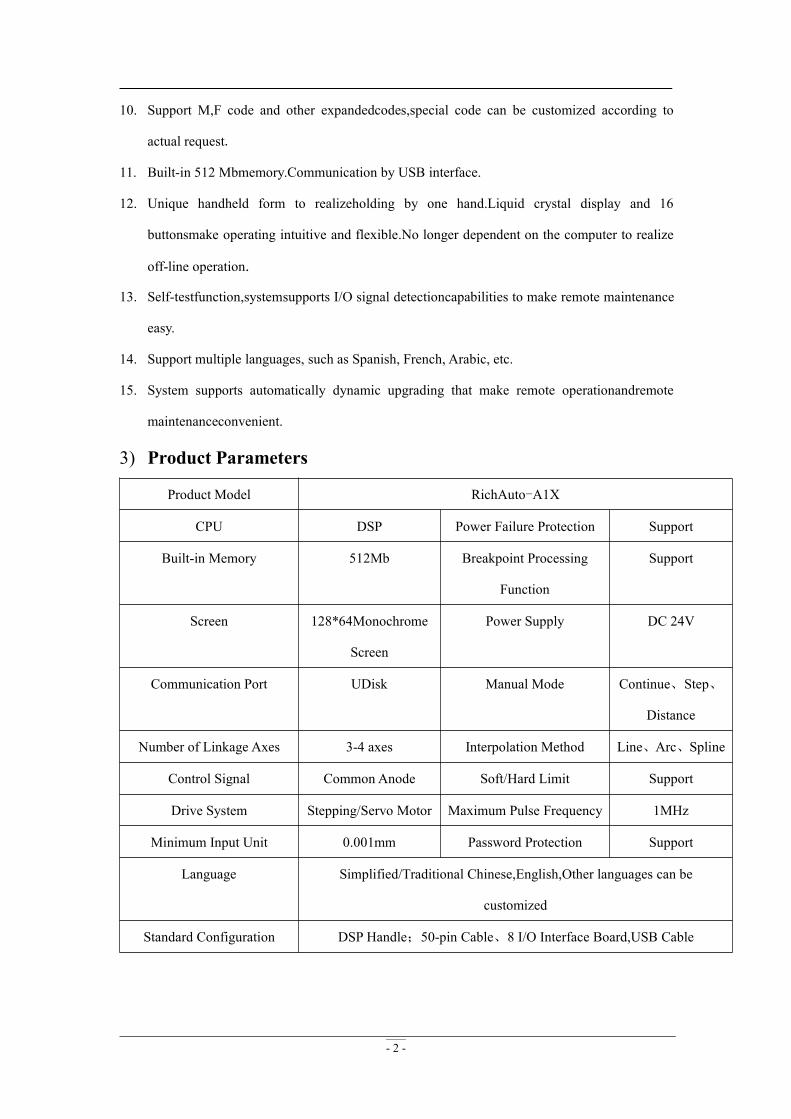
3) Product Parameters
Product Model RichAuto-A1X
CPU DSP Power Failure Protection Support
Built-in Memory 512Mb Breakpoint Processing
Function
Support
Screen 128*64Monochrome
Screen
Power Supply DC 24V
Communication Port UDisk Manual Mode Continue、Step、
Distance
Number of Linkage Axes 3-4 axes Interpolation Method Line、Arc、Spline
Control Signal Common Anode Soft/Hard Limit Support
Drive System Stepping/Servo Motor Maximum Pulse Frequency 1MHz
Minimum Input Unit 0.001mm Password Protection Support
Language Simplified/Traditional Chinese,English,Other languages can be
customized
Standard Configuration DSP Handle;50-pin Cable、8 I/O Interface Board,USB Cable
- 3 -
4) Product Model
AutoNowA1X Motion Control
System
Model NameA11 Three-axis Linkage Motion Control SystemA12 Plasma Cutting Motion Control SystemA14 Dispensor Motion Control SystemA15 Multi-spindle Motion Control SystemA115 Double Z Motion Control SystemA16 Side-spindle Motion Control SystemA18 Four-axis Linkage Motion Control SystemA123 Four-axis Linkage+ Multi-spindle Motion Control
SystemA132 Lathe Motion Control System
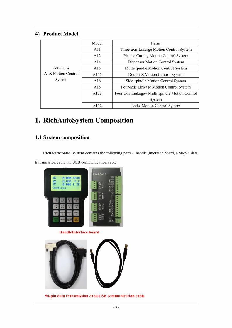
1. RichAutoSystem Composition
1.1 System composition
RichAutocontrol system contains the following parts:handle ,interface board, a 50-pin data
transmission cable, an USB communication cable.
HandleInterface board
50-pin data transmission cableUSB communication cable
- 4 -
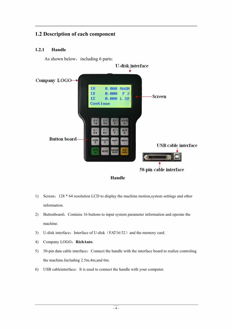
1.2 Description of each component
1.2.1 Handle
As shown below,including 6 parts:
Handle
1) Screen:128 * 64 resolution LCD to display the machine motion,system settings and other
information.
2) Buttonboard:Contains 16 buttons to input system parameter information and operate the
machine.
3) U-disk interface:Interface of U-disk(FAT16/32)and the memory card.
4) Company LOGO:RichAuto.
5) 50-pin data cable interface:Connect the handle with the interface board to realize controling
the machine.Including 2.5m,4m,and 6m.
6) USB cableinterface:It is used to connect the handle with your computer.
- 5 -
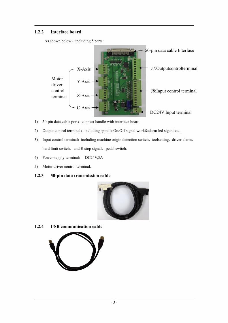
1.2.2 Interface board
As shown below,including 5 parts:
1) 50-pin data cable port:connect handle with interface board.
2) Output control terminal:including spindle On/Off signal,work&alarm led siganl etc..
3) Input control terminal:including machine origin detection switch,toolsetting,driver alarm,
hard limit switch,and E-stop signal,pedal switch.
4) Power supply terminal: DC24V,3A
5) Motor driver control terminal.
1.2.3 50-pin data transmission cable
1.2.4 USB communication cable
50-pin data cable Interface
J7:Outputcontrolterminal
J8:Input control terminal
DC24V Input terminal
Motordrivercontrolterminal
X-Axis
Y-Axis
Z-Axis
C-Axis
- 6 -
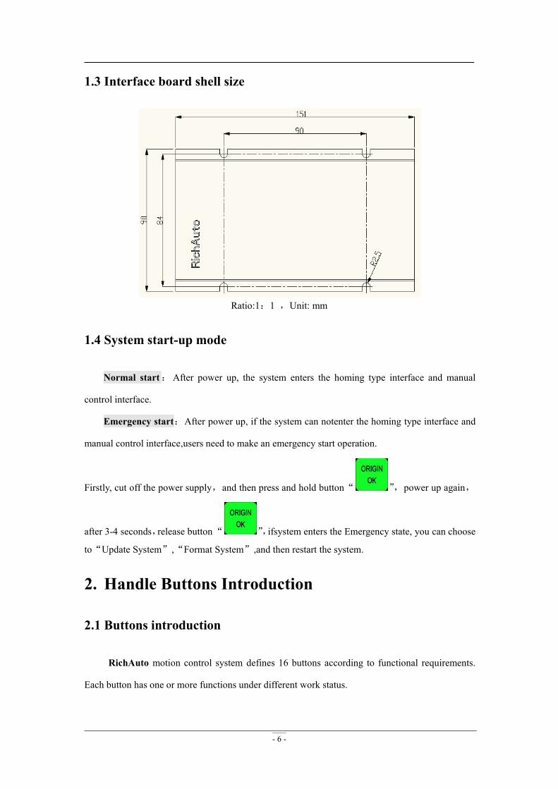
1.3 Interface board shell size
Ratio:1:1 ,Unit: mm
1.4 System start-up mode
Normal start:After power up, the system enters the homing type interface and manual
control interface.
Emergency start:After power up, if the system can notenter the homing type interface and
manual control interface,users need to make an emergency start operation.
Firstly, cut off the power supply,and then press and hold button“ ”,power up again,
after 3-4 seconds,release button“ ”,ifsystem enters the Emergency state, you can choose
to“Update System”,“Format System”,and then restart the system.
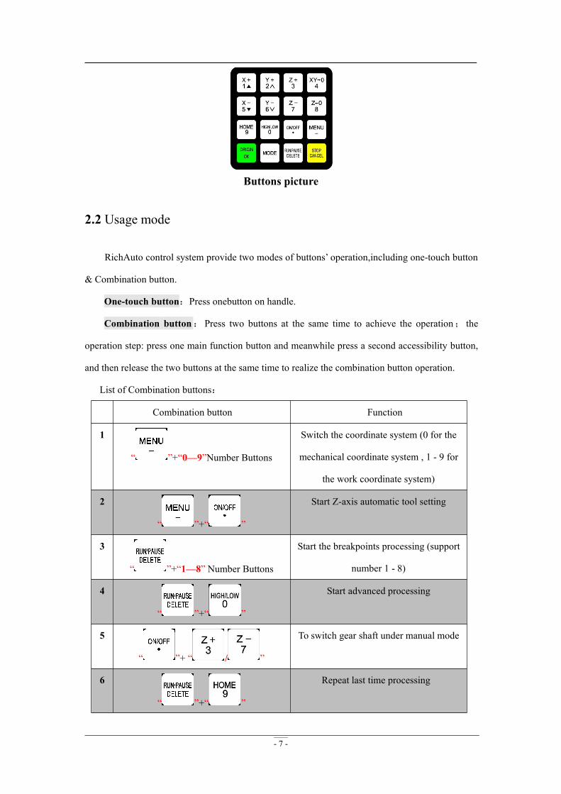
2. Handle Buttons Introduction
2.1 Buttons introduction
RichAuto motion control system defines 16 buttons according to functional requirements.
Each button has one or more functions under different work status.
- 7 -
Buttons picture
2.2 Usage mode
RichAuto control system provide two modes of buttons’ operation,including one-touch button
& Combination button.
One-touch button:Press onebutton on handle.
Combination button:Press two buttons at the same time to achieve the operation; the
operation step: press one main function button and meanwhile press a second accessibility button,
and then release the two buttons at the same time to realize the combination button operation.
List of Combination buttons:
Combination button Function
1
“ ”+“0—9”Number Buttons
Switch the coordinate system (0 for the
mechanical coordinate system , 1 - 9 for
the work coordinate system)
2
“ ”+“ ”
Start Z-axis automatic tool setting
3
“ ”+“1—8” Number Buttons
Start the breakpoints processing (support
number 1 - 8)
4
“ ”+“ ”
Start advanced processing
5
“ ”+ “ / ”
To switch gear shaft under manual mode
6
“ ”+“ ”
Repeat last time processing
- 8 -
7
“ ” +“ ”
Set stop position
8
“ ”+“ ”
System upgrade
9
“ ”+“ ”
Quit buttons check
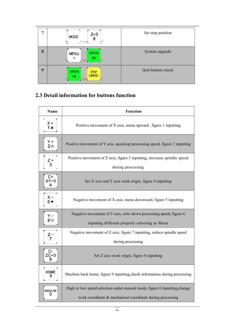
2.3 Detail information for buttons function
Name Function
Positive movement of X axis, menu upward , figure 1 inputting
Positive movement of Y axis, speed-up processing speed, figure 2 inputting
Positive movement of Z axis, figure 3 inputting, increase spindle speed
during processing
Set X axis and Y axis work origin, figure 4 inputting
Negative movement of X axis, menu downward, figure 5 inputting
Negative movement of Y axis, solw down processing speed, figure 6
inputting different property selecting in Menu
Negative movement of Z axis, figure 7 inputting, reduce spindle speed
during processing
Set Z axis work origin, figure 8 inputting
Machine back home, figure 9 inputting,check information during processing
High or low speed selection under manual mode, figure 0 inputting,change
work coordinate & mechanical coordinate during processing
- 9 -
Spindle start/stop, decimal point inputting
Enter menu setting, negative sign inputting ,check information during
processing
Back to work origin,confirm motions /inputting/operating
Manual mode, continue/step/distance to select
Run or pause processing,delete inputting data, different property selecting in
menu
High/low speed parameter adjust under manual mode, quit process
stop/selections, inputting and operating cancel
3. Wiring Instructions
3.1 RichAutointerface board description
- 10 -
3.2 Interface board I / O description
Port
lable
Port
definition
Signal
description
Pin functions
and parametersNotes
DC24V
24V+ +24V DC power input Supply DC24V for
interface board
24V(≧3A)
24V- Power GND
X_A
XIS
5V Common anode Output 5V Do not imposevoltage on thispin
PULSE X axis pulse signal Output voltage≧ 3V;
Drive current≦8mA
DIR X axis direction signal Output voltage≧ 3V;
Drive current≦8mA
SHIELD Shielded signal Do not imposevoltage
Y_A
XIS
5V Common anode Output 5V Do not imposevoltage on thispin
PULSE Y axis pulse signal Output voltage≧ 3V;
Drive current≦8mA
DIR Y axis direction signal Output voltage≧ 3V;
Drive current≦8mA
SHIELD Shielded signal Not GNDZ_A
XIS
5V Common anode Output 5V Do not imposevoltage
PULSE Z axis pulse signal Output voltage≧ 3V;
Drive current≦8mA
DIR Z axis direction signal Output voltage≧ 3V;
Drive current≦8mA
SHIELD Shielded signal Not GND
C_A
XIS
5V Common anode Output 5V Do not imposevoltage on thispin
PULSE C axis pulse signal Output voltage≧ 3V;
Drive current≦8mA
DIR C axis direction signal Output voltage≧ 3V;
Drive current≦8mA
SHIELD Shielded signal Not GND
- 11 -
Port
lable
Port
definition
Signaldescription Pin functions
and parametersNotes
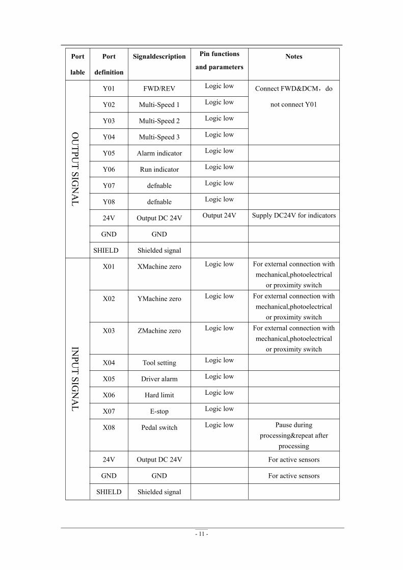
OUTPU
TSIG
NAL
Y01 FWD/REV Logic low Connect FWD&DCM,do
not connect Y01Y02 Multi-Speed 1 Logic low
Y03 Multi-Speed 2 Logic low
Y04 Multi-Speed 3 Logic low
Y05 Alarm indicator Logic low
Y06 Run indicator Logic low
Y07 defnable Logic low
Y08 defnable Logic low
24V Output DC 24V Output 24V Supply DC24V for indicators
GND GND
SHIELD Shielded signal
INPU
TSIG
NAL
X01 XMachine zero Logic low For external connection withmechanical,photoelectrical
or proximity switch
X02 YMachine zero Logic low For external connection withmechanical,photoelectrical
or proximity switch
X03 ZMachine zero Logic low For external connection withmechanical,photoelectrical
or proximity switch
X04 Tool setting Logic low
X05 Driver alarm Logic low
X06 Hard limit Logic low
X07 E-stop Logic low
X08 Pedal switch Logic low Pause duringprocessing&repeat after
processing
24V Output DC 24V For active sensors
GND GND For active sensors
SHIELD Shielded signal
- 12 -
3.3 Hardware wiring
Installation Requirements:Power(24V,3A),it is better to add a filter to prevent the electric
field interference.Ifchoosing origin detecting switches of different power supply type, the special
testing switching power is needed.(24V origin detecting switch is the best choice)
RichAuto control system realizes its control through the connection between the interface
board and CNC machine. Interface board terminal can be divided into input terminal and output
terminal
Input terminal:INPUT SIGNAL DC24V(Power Supply)
Output terminal:X,Y,Z,C axis pulse signal output terminal,OUTPUT SIGNAL
Input terminal
Power Supply
INPUT SIGNAL
1. Machine OriginY and Z are the same as X
MechanicalNPN(NO)
PNP(NO)
- 13 -
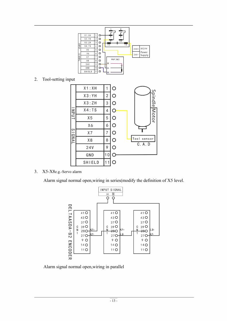
2. Tool-setting input
3. X5-X8e.g.-Servo alarm
Alarm signal normal open,wiring in series(modify the definition of X5 level.
Alarm signal normal open,wiring in parallel
- 14 -
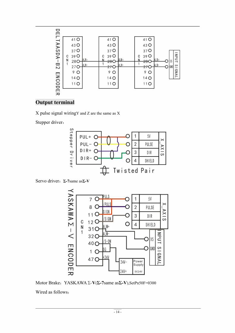
Output terminal
X pulse signal wiringY and Z are the same as X
Stepper driver:
Servo driver:Σ-7same asΣ-V
Motor Brake:YASKAWAΣ-V(Σ-7same asΣ-V),SetPn50F=0300
Wired as follows:
- 15 -
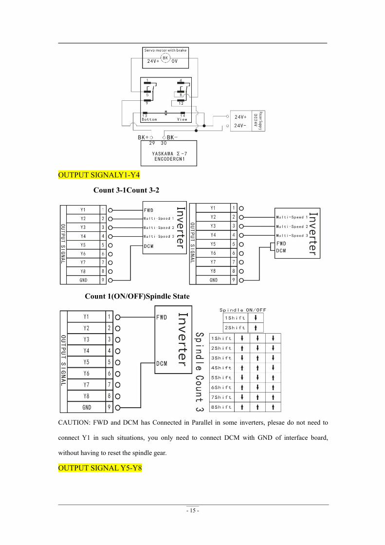
OUTPUT SIGNALY1-Y4
Count 3-1Count 3-2
Count 1(ON/OFF)Spindle State
CAUTION: FWD and DCM has Connected in Parallel in some inverters, plesae do not need to
connect Y1 in such situations, you only need to connect DCM with GND of interface board,
without having to reset the spindle gear.
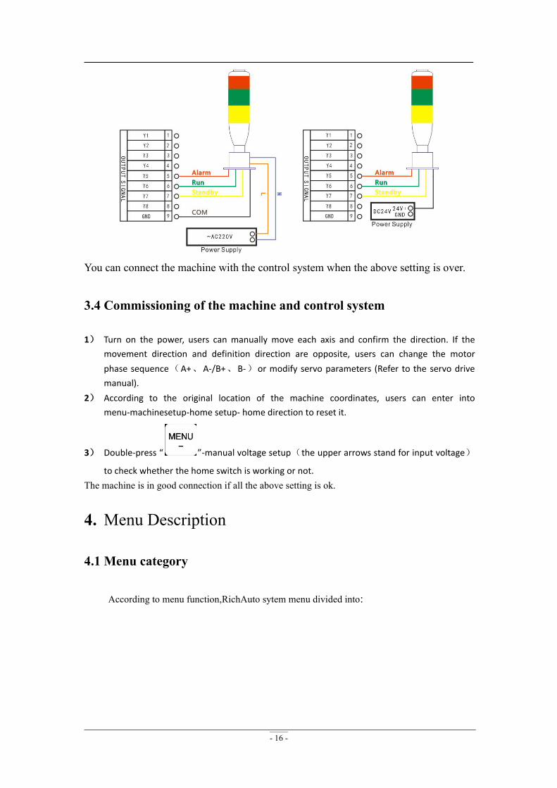
OUTPUT SIGNALY5-Y8
- 16 -
You can connect the machine with the control system when the above setting is over.
3.4 Commissioning of the machine and control system
1) Turn on the power, users can manually move each axis and confirm the direction. If themovement direction and definition direction are opposite, users can change the motorphase sequence(A+、A-/B+、B-)or modify servo parameters (Refer to the servo drivemanual).
2) According to the original location of the machine coordinates, users can enter intomenu-machinesetup-home setup- home direction to reset it.
3) Double-press “ ”-manual voltage setup(the upper arrows stand for input voltage)
to check whether the home switch is working or not.The machine is in good connection if all the above setting is ok.
4. Menu Description
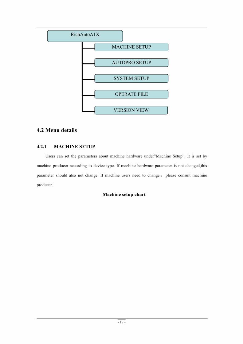
4.1 Menu category
According to menu function,RichAuto sytem menu divided into:
- 17 -
RichAutoA1X
MACHINE SETUP
AUTOPRO SETUP
SYSTEM SETUP
OPERATE FILE
VERSION VIEW
4.2 Menu details
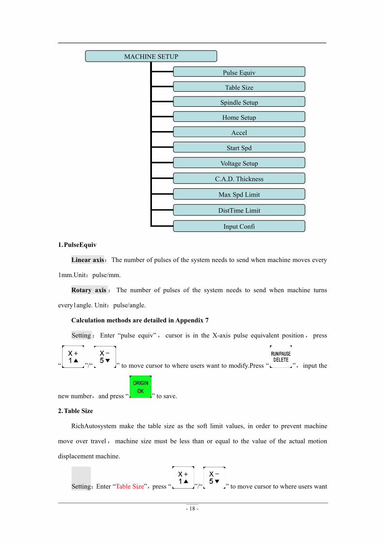
4.2.1 MACHINE SETUP
Users can set the parameters about machine hardware under”Machine Setup”. It is set by
machine producer according to device type. If machine hardware parameter is not changed,this
parameter should also not change. If machine users need to change, please consult machine
producer.
Machine setup chart
- 18 -
MACHINE SETUP
Pulse Equiv
Table Size
Spindle Setup
Home Setup
Accel
Start Spd
Voltage Setup
C.A.D. Thickness
Max Spd Limit
DistTime Limit
Input Confi
1.PulseEquiv
Linear axis:The number of pulses of the system needs to send when machine moves every
1mm.Unit:pulse/mm.
Rotary axis: The number of pulses of the system needs to send when machine turns
every1angle. Unit:pulse/angle.
Calculation methods are detailed in Appendix 7
Setting: Enter “pulse equiv”, cursor is in the X-axis pulse equivalent position, press
“ ”/“ ” to move cursor to where users want to modify.Press “ ”,input the
new number,and press “ ” to save.
2.Table Size
RichAutosystem make the table size as the soft limit values, in order to prevent machine
move over travel,machine size must be less than or equal to the value of the actual motion
displacement machine.
Setting:Enter “Table Size”,press “ ”/“ ” to move cursor to where users want
- 19 -
to modify.Press “ ”,input the new number,press “ ” to save.
3.Spindle Setup
Spindle delay:Unit:ms;including start delay and stop delay.
Spindle state:Used to set Spindle states ---multi-speed or only on/off status.See detailed
settings at OUTPUT SIGNAL-spindle output wiring.
4.Home Setup
Home speed: Every axis movement speed when back home,system default speed X.Y:
3000mm/minute, Z: 1800mm/minute.
Home order:Every axis movement order when back home
Including:
Z,X and YZ,X,YZ,Y,X
Z onlyX and Y,ZX,Y,Z
Y,X,ZXY homeX,Y home
Y,X homeNone home X home only XZ and Y
Home direction:Every axis movement direction when backhome,thisdirctiondepends on the
position where home switch is on the machine.Ifhome switch installed in the positive direction,so
home direction should be“positive” ,and vice versa.
Setting:Enter “home dir”,press “ ”/“ ” to move cursor to where users want to
modify.Press“ ” to change home direction,press “ ” to save the change.
5.Accel(Acceleration)Unit:mm/s2
The maximum acceleration valueduring acceleration and deceleration movement, improve
(including straight and curved motion) processing capabilities. If acceleration is too large, it may
cause the motor losing steps, jitter and even whistle, if too small, it will lead to accelerated slowly
and reduce the operating speed of the entire graph. System default:linear acceleration is 800 mm/s2,
curve acceleration is 1000 mm/s2, the proposed curve acceleration is 1-1.5 times the linear
acceleration value.
6.Start SpeedUnit:mm/minute
- 20 -
The speed of axis started directly from standstill. Not starting from zero speed, but starting
directly from a certain speed,so it can shorten the overall processing time,but do not set this speed
too high. Set too high, it will cause the motor losing steps, jitter and even whistle;Set too small, it
will reduce the operating speed of the entire graph. If the inertia of motion axes (axis heavier),
users can set a smaller start speed, if the inertia of motion axes smaller (lighter shaft), users can set
itbigger.
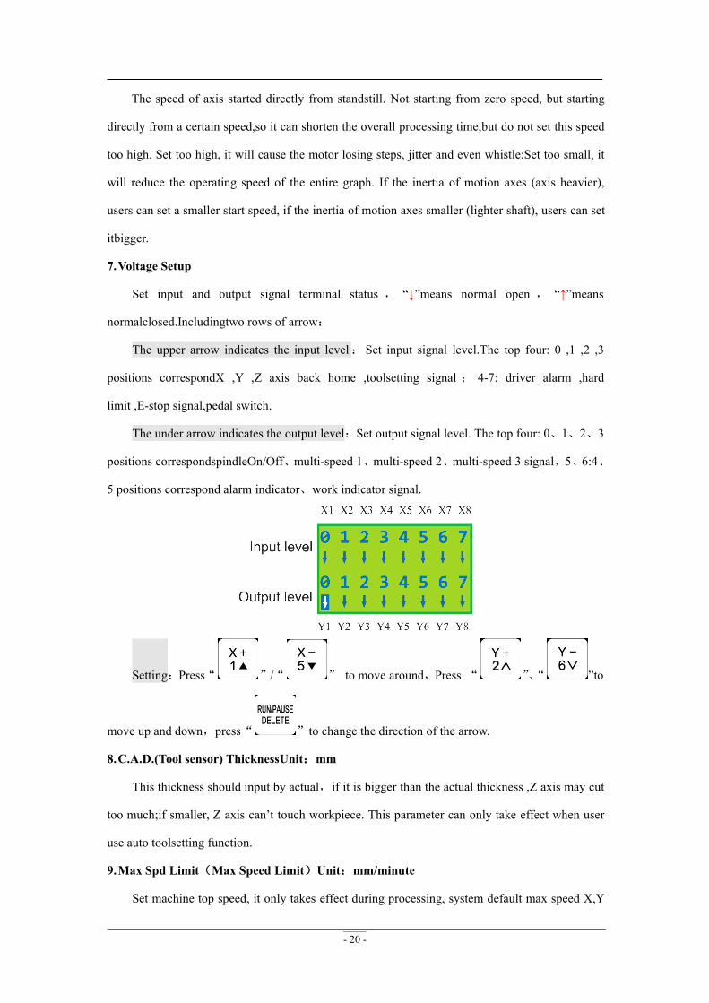
7.Voltage Setup
Set input and output signal terminal status , “↓”means normal open , “↑”means
normalclosed.Includingtwo rows of arrow:
The upper arrow indicates the input level:Set input signal level.The top four: 0 ,1 ,2 ,3
positions correspondX ,Y ,Z axis back home ,toolsetting signal ; 4-7: driver alarm ,hard
limit ,E-stop signal,pedal switch.
The under arrow indicates the output level:Set output signal level. The top four: 0、1、2、3
positions correspondspindleOn/Off、multi-speed 1、multi-speed 2、multi-speed 3 signal,5、6:4、
5 positions correspond alarm indicator、work indicator signal.
Setting:Press“ ”/“ ” to move around,Press “ ”、“ ”to
move up and down,press“ ”to change the direction of the arrow.
8.C.A.D.(Tool sensor) ThicknessUnit:mm
This thickness should input by actual,if it is bigger than the actual thickness ,Z axis may cut
too much;if smaller, Z axis can’t touch workpiece. This parameter can only take effect when user
use auto toolsetting function.
9.Max Spd Limit(Max Speed Limit)Unit:mm/minute
Set machine top speed, it only takes effect during processing, system default max speed X,Y
- 21 -
is“60000000 mm/minute”, “Z+” is “1800 mm/minute”, “Z-” is “3000 mm/minute”.
10. DistTime LimitUnit:second
Users select diatancemode,and if the machine does not move in a certain period of
time(system default is 30 seconds),the system will go back to continuous mode to prevent Z-axis
collision risk because of the customer forgot to switch back to continuous mode and set a large
distance value.
11. InputConfi(Input Port Configuration)
To open or prohibitinput signal,if the interface board does not connect X5-X8 signals,users
can prohibit X5-X8 signals.
Setting:Press “ ”、“ ”to move up and down,press“ ”to change
enable or disable,and then press“ ”to confirm.
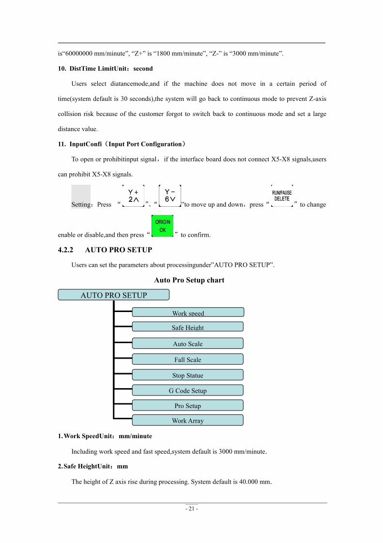
4.2.2 AUTO PRO SETUP
Users can set the parameters about processingunder”AUTO PRO SETUP”.
Auto Pro Setup chart
AUTO PRO SETUP
Work speed
Safe Height
Auto Scale
Fall Scale
Stop Statue
G Code Setup
Pro Setup
Work Array
1.Work SpeedUnit:mm/minute
Including work speed and fast speed,system default is 3000 mm/minute.
2.Safe HeightUnit:mm
The height of Z axis rise during processing. System default is 40.000 mm.
- 22 -
3.Auto Scale
Actual processing speed=work speed*auto scale,system default auto scale does not affect the
fast speed.
4.Fall Scale
Fall scale,system default is 0.200.fall speed=fast speed*fall scale,the maximum fall speed is
Z axis negative limit speed*fall scale.
Fall height,system default is 5.000mm,fall down scale takes effect when the spindle falls to
the fall height.
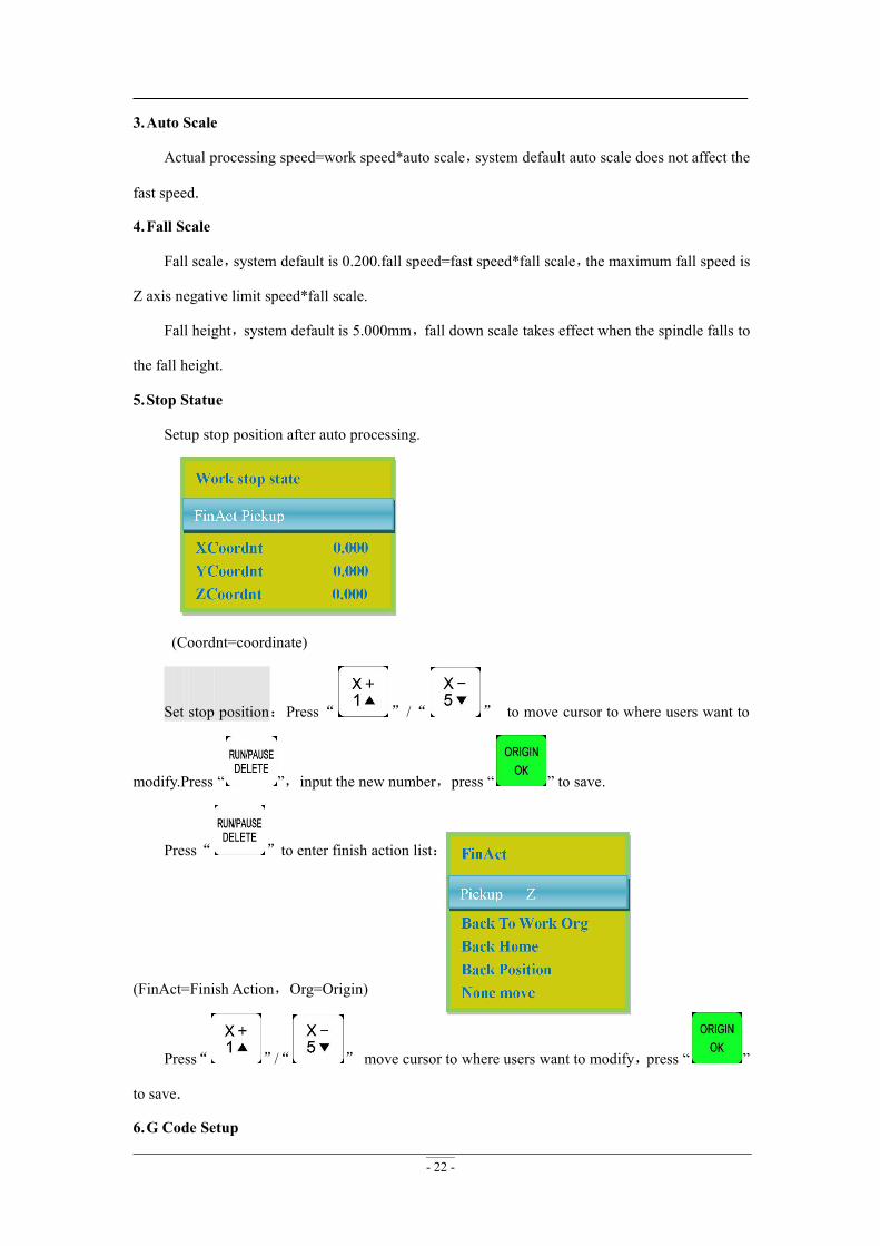
5.Stop Statue
Setup stop position after auto processing.
(Coordnt=coordinate)
Set stop position:Press“ ”/“ ” to move cursor to where users want to
modify.Press “ ”,input the new number,press “ ” to save.
Press“ ”to enter finish action list:
(FinAct=Finish Action,Org=Origin)
Press“ ”/“ ” move cursor to where users want to modify,press “ ”
to save.
6.G Code Setup
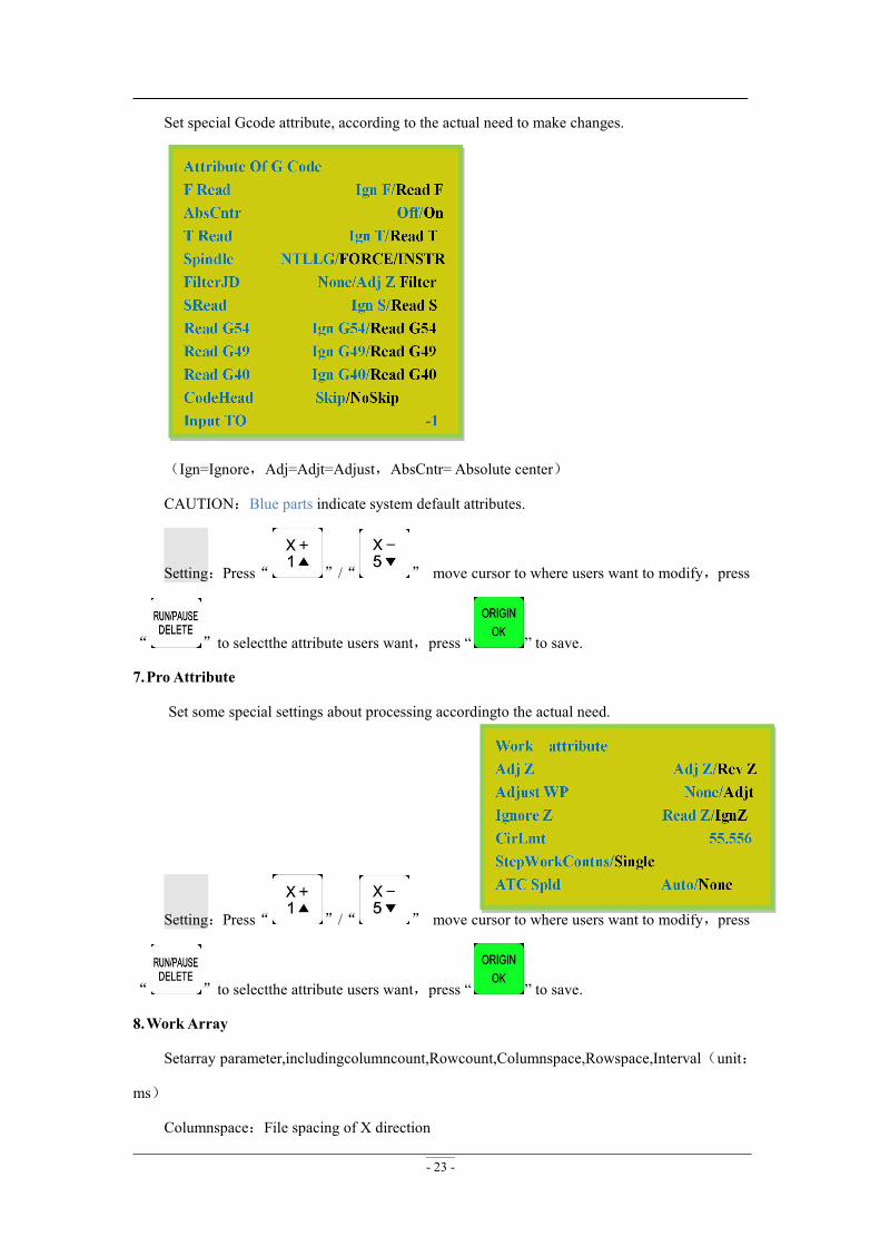
- 23 -
Set special Gcode attribute, according to the actual need to make changes.
(Ign=Ignore,Adj=Adjt=Adjust,AbsCntr= Absolute center)
CAUTION:Blue parts indicate system default attributes.
Setting:Press“ ”/“ ” move cursor to where users want to modify,press
“ ”to selectthe attribute users want,press “ ” to save.
7.Pro Attribute
Set some special settings about processing accordingto the actual need.
Setting:Press“ ”/“ ” move cursor to where users want to modify,press
“ ”to selectthe attribute users want,press “ ” to save.
8.Work Array
Setarray parameter,includingcolumncount,Rowcount,Columnspace,Rowspace,Interval(unit:
ms)
Columnspace:File spacing of X direction
- 24 -
Rowspace:File spacing of Y direction
Total Processing times=columncount*Rowcount
Interval:System default 0,it means no wait.
During processing , if users need to change processing materials after completion of
eachprocessing,youneed set time interval a negative number.When the first time processing is
completed, the screen prompt: waiting for the next array processing, press any key to start the next
array processing at this time, if not press,system keep waiting.
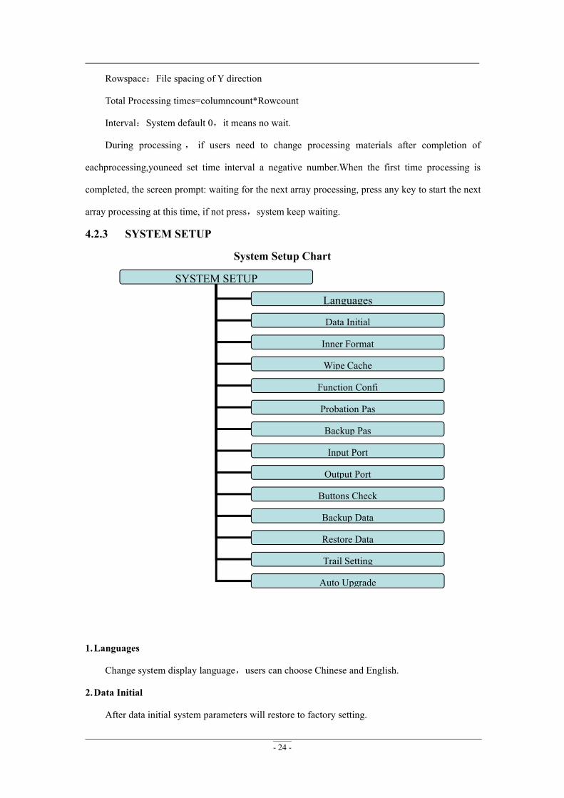
4.2.3 SYSTEM SETUP
System Setup Chart
SYSTEM SETUP
Languages
Data Initial
Inner Format
Wipe Cache
Function Confi
Probation Pas
Backup Pas
Input Port
Output Port
Buttons Check
Backup Data
Restore Data
Trail Setting
Auto Upgrade
1.Languages
Change system display language,users can choose Chinese and English.
2.Data Initial
After data initial system parameters will restore to factory setting.
- 25 -
3.Inner Format
Wipe the internal files,itwill not damage the system parameters.
4.Wipe Cache
Users need to do this after functional upgrade, such as change four-axis program to three-axis
program,users must do this operation.After this operation ,users need to restart the system.
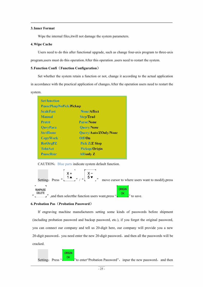
5.Function Confi(Function Configuration)
Set whether the system retain a function or not, change it according to the actual application
in accordance with the practical application of changes.After the operation users need to restart the
system.
CAUTION:Blue parts indicate system default function.
Setting:Press“ ”/“ ” move cursor to where users want to modify,press
“ ”,and then selectthe function users want,press “ ” to save.
6.Probation Pas(Probation Password)
If engraving machine manufacturers setting some kinds of passwords before shipment
(including probation password and backup password, etc.), if you forget the original password,
you can connect our company and tell us 20-digit here, our company will provide you a new
20-digit password,you need enter the new 20-digit password,and then all the passwords will be
cracked.
Setting:Press “ ”to enter“Probation Password”,inpur the new password,and then
- 26 -
press“ ”to save.
7.Backup Pas(Backup Password)
Prevent users overwritten the original correct parametersin the parameter backup disorder or
misuse case. To cancel, you do not input any number when you are prompted to enter a new
password,press " " to save.
8.Input Port(Input Port List)
1-3:X,Y,Z home signal4: Tool setting input signal
5-8:Driver alarm,Hardlimit,E-stop,pedal switch signal
9.Output Port(Output Port List)
1:Spindle On/Off signal 2-4: Spindle speed signal 5: Alarm indicator signal
6:Work indicator signal
10. Buttons Check
Users can check buttons are valid or not under this menu.Enter“Buttons Check”,press every
button,if it is valid,the screen will highlight.Exit“Buttons Check”,press“ ”+“ ”.
11. Backup Data
Backup system parameters to U disk or inner,format system can’t effect this.File format:
data.bak.
12. Restore Data
Restore backup data from U disk or inner to system.
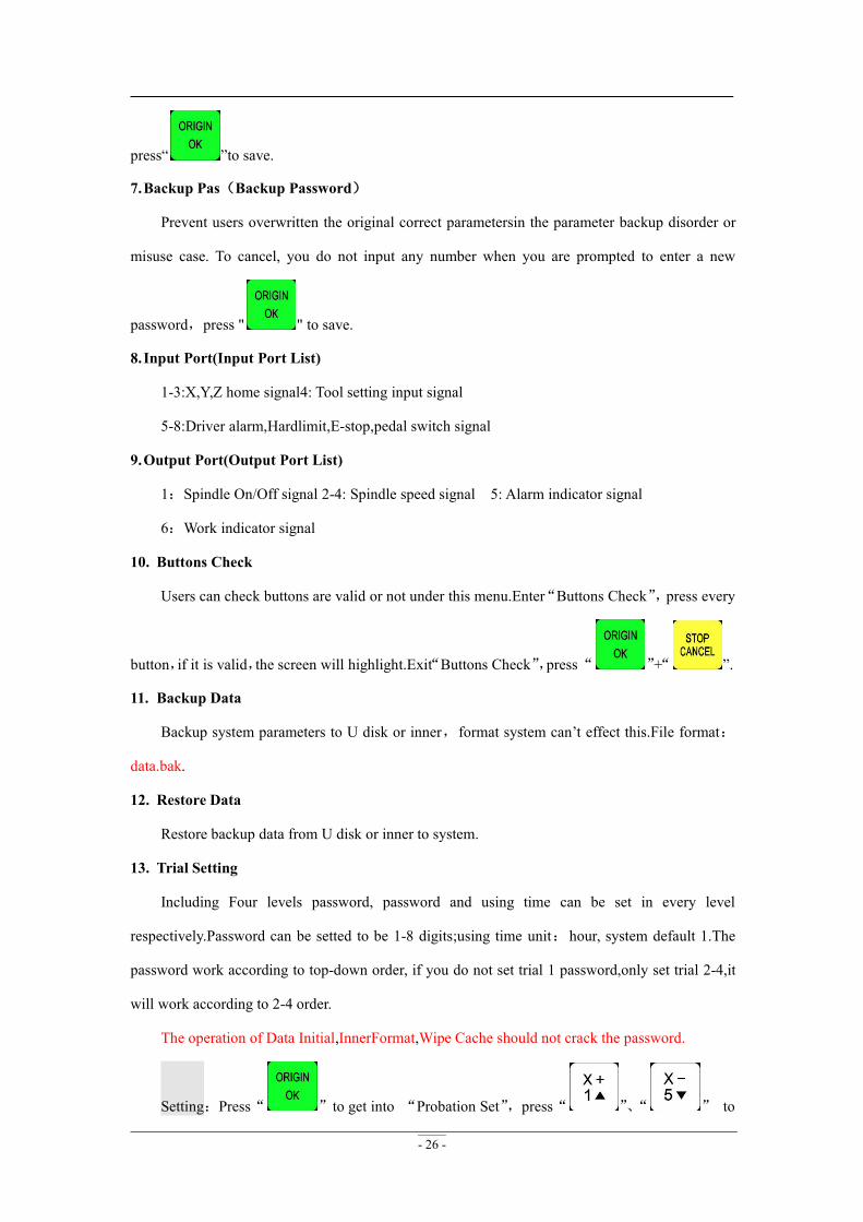
13. Trial Setting
Including Four levels password, password and using time can be set in every level
respectively.Password can be setted to be 1-8 digits;using time unit:hour, system default 1.The
password work according to top-down order, if you do not set trial 1 password,only set trial 2-4,it
will work according to 2-4 order.
The operation of Data Initial,InnerFormat,Wipe Cache should not crack the password.
Setting:Press“ ”to get into “Probation Set”,press“ ”、“ ” to
- 27 -
move cursor to which you want to choose.Press“ ”to get into,and then press“ ”,
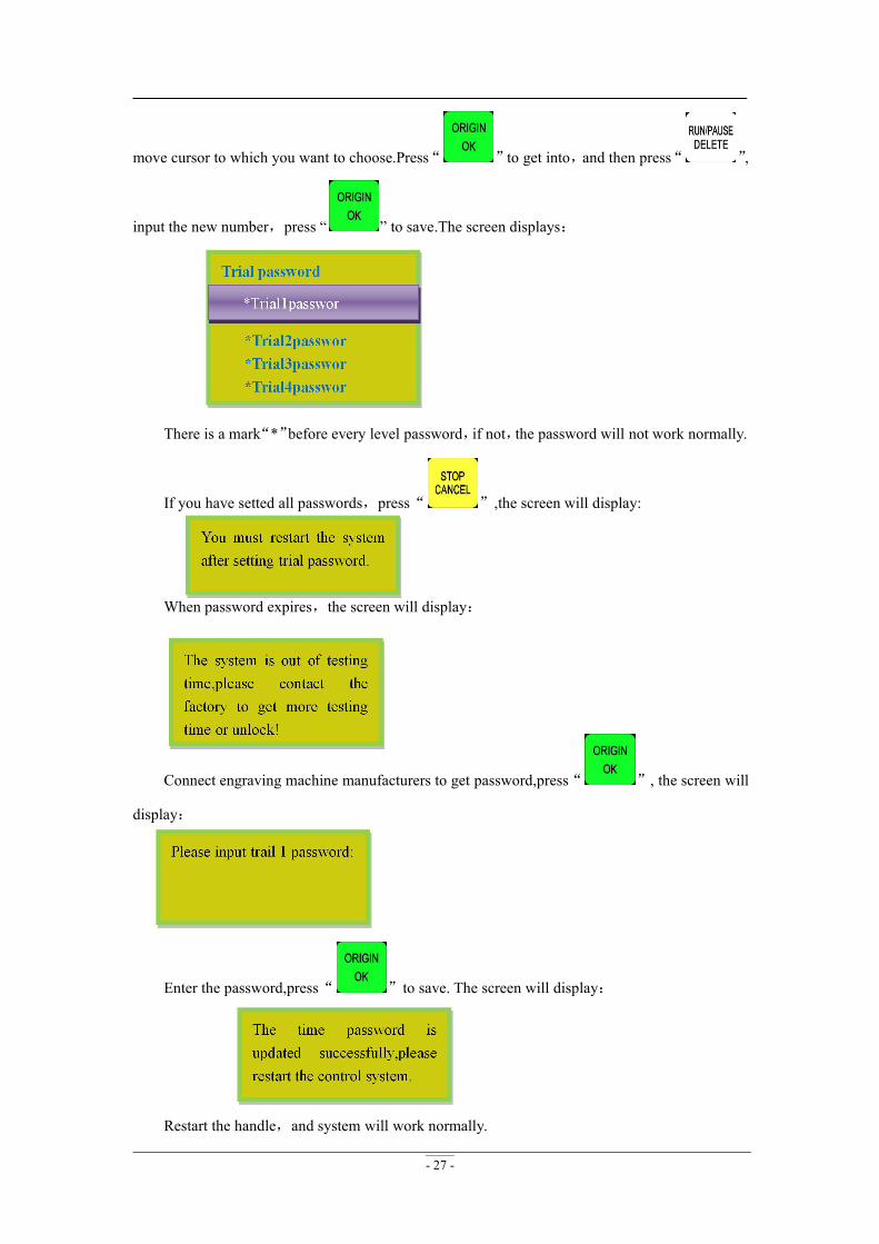
input the new number,press “ ” to save.The screen displays:
There is a mark“*”before every level password,if not,the password will not work normally.
If you have setted all passwords,press“ ”,the screen will display:
When password expires,the screen will display:
Connect engraving machine manufacturers to get password,press“ ”, the screen will
display:
Enter the password,press“ ”to save. The screen will display:
Restart the handle,and system will work normally.

- 28 -
NOTE: If engraving machine manufacturers forgot all password, you can contact our
company and tell us 20-digit original password under“SYSTEM SETUP-Probation pas”,we will
provide the new 20-digit password, entered the new number,and press “ ”to confirm.
After Cracking Password, restart the handle,and then you can work normally.
14. Auto Upgrade
If the system has new function,our company will provide upgrade file(extension ******.
PKG&shown as rz-xxxx), users can upgrade through the U disk, specific steps in Appendix 1. It
will not damage the original parameters.
File fomat:
4.2.4 OPERATE FILE
Operate File Chart
OPERATE FILE
Copy File
Del File
View File
Pro Info
Check Pro Time
1.Copy File
Copy files from U disk to Inner.
2.Del File(Delete File)
Delete files of inner.
3.View File
View the files and G codes of U disk or inner.
4.Pro Info(Processing Information)
System power on,it will statistical thetimes of successful processing by file name,if system
- 29 -
power off,the data will disappear.
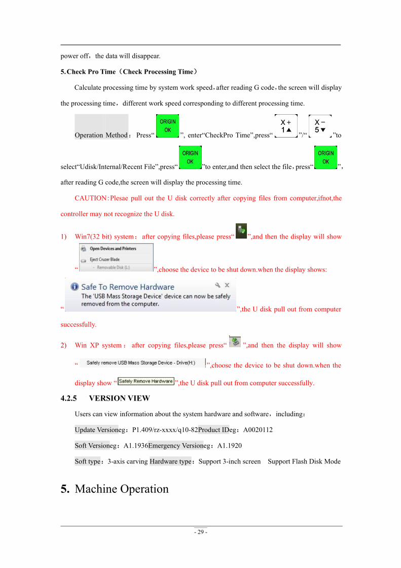
5.Check Pro Time(Check Processing Time)
Calculate processing time by system work speed,after reading G code,the screen will display
the processing time,different work speed corresponding to different processing time.
Operation Method:Press“ ”, enter“CheckPro Time”,press“ ”/“ ”to
select“Udisk/Internal/Recent File”,press“ ”to enter,and then select the file,press“ ”,
after reading G code,the screen will display the processing time.
CAUTION:Plesae pull out the U disk correctly after copying files from computer,ifnot,the
controller may not recognize the U disk.
1) Win7(32 bit) system:after copying files,please press“ ”,and then the display will show
“ ”,choose the device to be shut down.when the display shows:
“ ”,the U disk pull out from computer
successfully.
2) Win XP system: after copying files,please press“ ”,and then the display will show
“ ”,choose the device to be shut down.when the
display show “ ”,the U disk pull out from computer successfully.
4.2.5 VERSION VIEW
Users can view information about the system hardware and software,including:
Update Versioneg:P1.409/rz-xxxx/q10-82Product IDeg:A0020112
Soft Versioneg:A1.1936Emergency Versioneg:A1.1920
Soft type:3-axis carving Hardware type:Support 3-inch screen Support Flash Disk Mode
5. Machine Operation
- 30 -
5.1 Return home
It will display “all axis home”, “Z home only”, “none axis home” after starting up the DSP
handle. Choose any one you want. Machine return home can correct the coordinate of system.
In some cases, such as after normal power off, reboot ad continue last operation, user no need
to reset machine, just choose “none axis home”. That is because system auto save coordinate
value when system quit.
5.2 Import processing files
Before processing, generally we should import files. RichAuto system has 2 ways for
processing: U disk file processing, inner file processing.
1. Directly import the processing file into U disk, then run the handle.
2. Copy the process file to inner memory space via U disk.
5.3 Manual operation
Manual Processing Operation refers to controlling of the machine tool though keyboard. User
can change the operate speed and set the grid under manual processing operation. System will
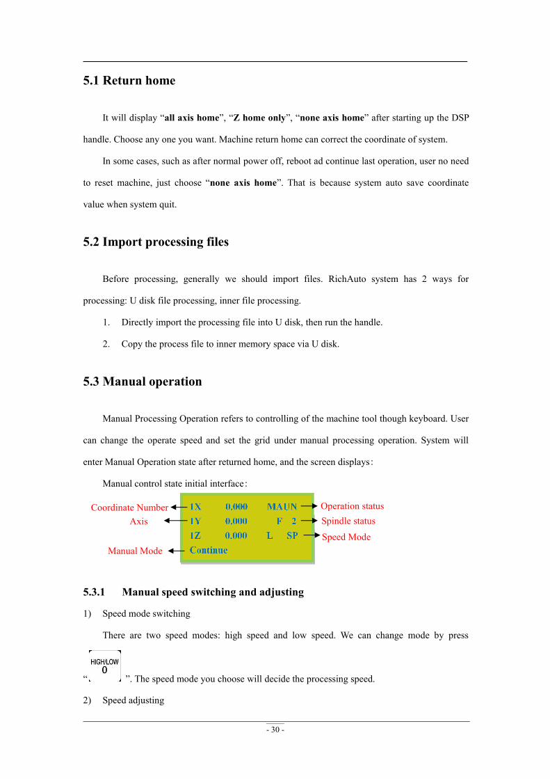
enter Manual Operation state after returned home, and the screen displays:
Manual control state initial interface:
5.3.1 Manual speed switching and adjusting
1) Speed mode switching
There are two speed modes: high speed and low speed. We can change mode by press
“ ”. The speed mode you choose will decide the processing speed.
2) Speed adjusting
Spindle statusOperation status
Speed ModeManual Mode
AxisCoordinate Number
- 31 -
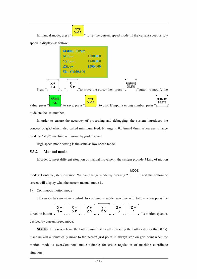
In manual mode, press “ ” to set the current speed mode. If the current speed is low
speed, it displays as follow:
Press “ ”、“ ”to move the cursor,then press “ ”button to modify the
value, press “ ” to save, press “ ” to quit. If input a wrong number, press “ ”
to delete the last number.
In order to ensure the accuracy of processing and debugging, the system introduces the
concept of grid which also called minimum feed. It range is 0.05mm-1.0mm.When user change
mode to “step”, machine will move by grid distance.
High speed mode setting is the same as low speed mode.
5.3.2 Manual mode
In order to meet different situation of manual movement, the system provide 3 kind of motion
modes: Continue, step, distance. We can change mode by pressing “ ”and the bottom of
screen will display what the current manual mode is.
1) Continuous motion mode
This mode has no value control. In continuous mode, machine will follow when press the
direction button 、 、 、 、 、 .Its motion speed is
decided by current speed mode.
NOTE:If uesers release the button immidiately after pressing the button(shorter than 0.5s),
machine will automatically move to the nearest grid point. It always stop on grid point when the
motion mode is over.Continous mode suitable for crude regulation of machine coordinate
situation.
- 32 -
2) Step motion mode
This mode is always move in low speed, move 1 grid per 0.5 second. The grid distance is
decided by current speed mode. This motion mode is suitable for tool adjusting or precise
adjustment of the location of the mechanical coordinates.
3) Distance motion mode
In this mode, it runs according to the setting of distance. Machine will move by the set
distance when user press direction button 、 、 、 、 、
.
NOTE:Grid unable to affect the distance motion mode. Machine will move by set distance,
can’t move to grid point. If user wants to change distance, please change to distance mode and
re-enter the distance value.
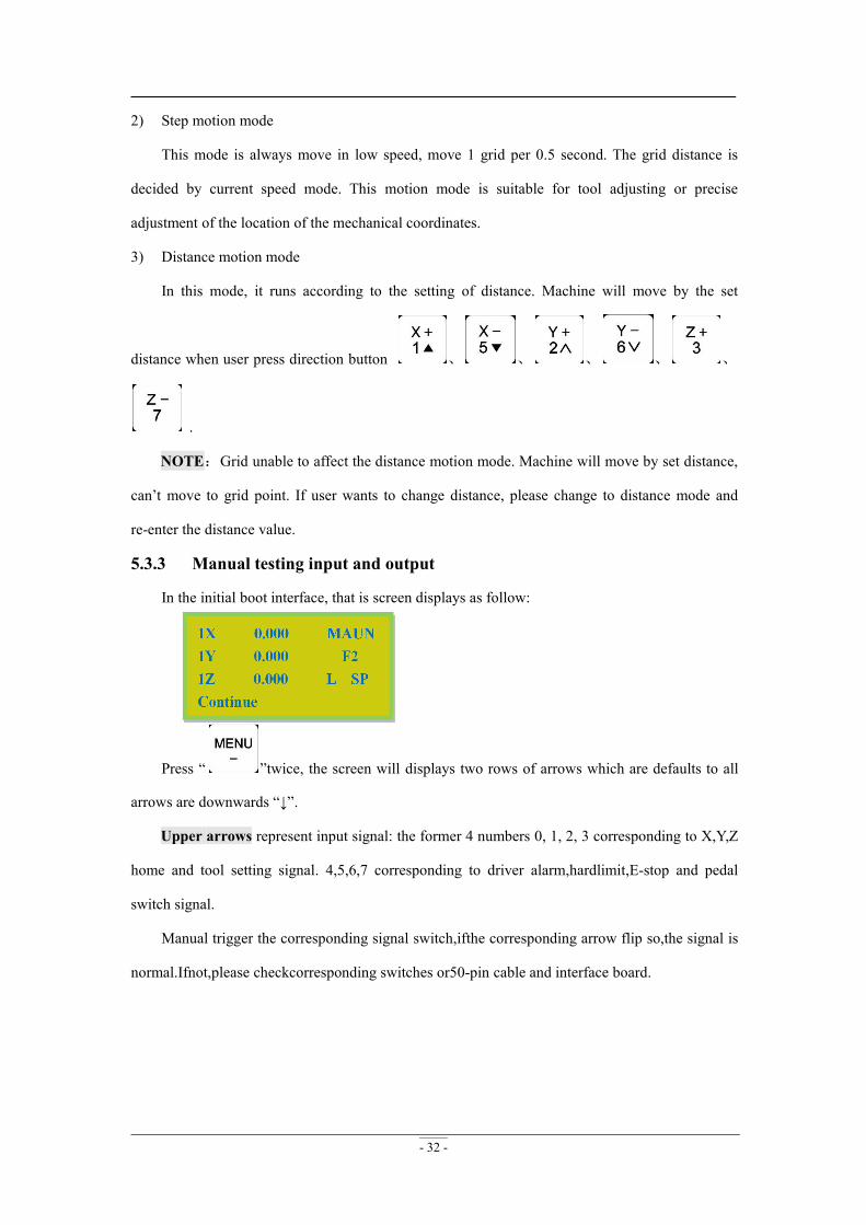
5.3.3 Manual testing input and output
In the initial boot interface, that is screen displays as follow:
Press “ ”twice, the screen will displays two rows of arrows which are defaults to all
arrows are downwards “↓”.
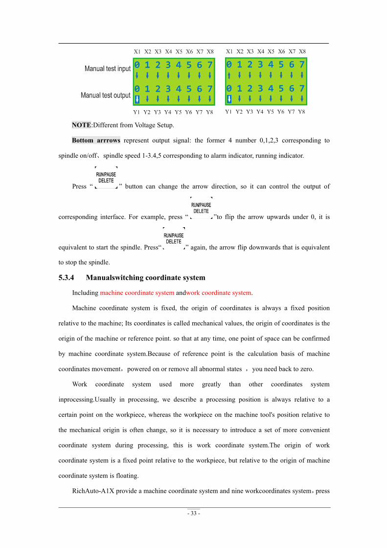
Upper arrows represent input signal: the former 4 numbers 0, 1, 2, 3 corresponding to X,Y,Z
home and tool setting signal. 4,5,6,7 corresponding to driver alarm,hardlimit,E-stop and pedal
switch signal.
Manual trigger the corresponding signal switch,ifthe corresponding arrow flip so,the signal is
normal.Ifnot,please checkcorresponding switches or50-pin cable and interface board.
- 33 -
NOTE:Different from Voltage Setup.
Bottom arrrows represent output signal: the former 4 number 0,1,2,3 corresponding to
spindle on/off、spindle speed 1-3.4,5 corresponding to alarm indicator, running indicator.
Press “ ” button can change the arrow direction, so it can control the output of
corresponding interface. For example, press “ ”to flip the arrow upwards under 0, it is
equivalent to start the spindle. Press“ ” again, the arrow flip downwards that is equivalent
to stop the spindle.
5.3.4 Manualswitching coordinate system
Including machine coordinate system andwork coordinate system.
Machine coordinate system is fixed, the origin of coordinates is always a fixed position
relative to the machine; Its coordinates is called mechanical values, the origin of coordinates is the
origin of the machine or reference point. so that at any time, one point of space can be confirmed
by machine coordinate system.Because of reference point is the calculation basis of machine
coordinates movement,powered on or remove all abnormal states ,you need back to zero.
Work coordinate system used more greatly than other coordinates system
inprocessing.Usually in processing, we describe a processing position is always relative to a
certain point on the workpiece, whereas the workpiece on the machine tool's position relative to
the mechanical origin is often change, so it is necessary to introduce a set of more convenient
coordinate system during processing, this is work coordinate system.The origin of work
coordinate system is a fixed point relative to the workpiece, but relative to the origin of machine
coordinate system is floating.
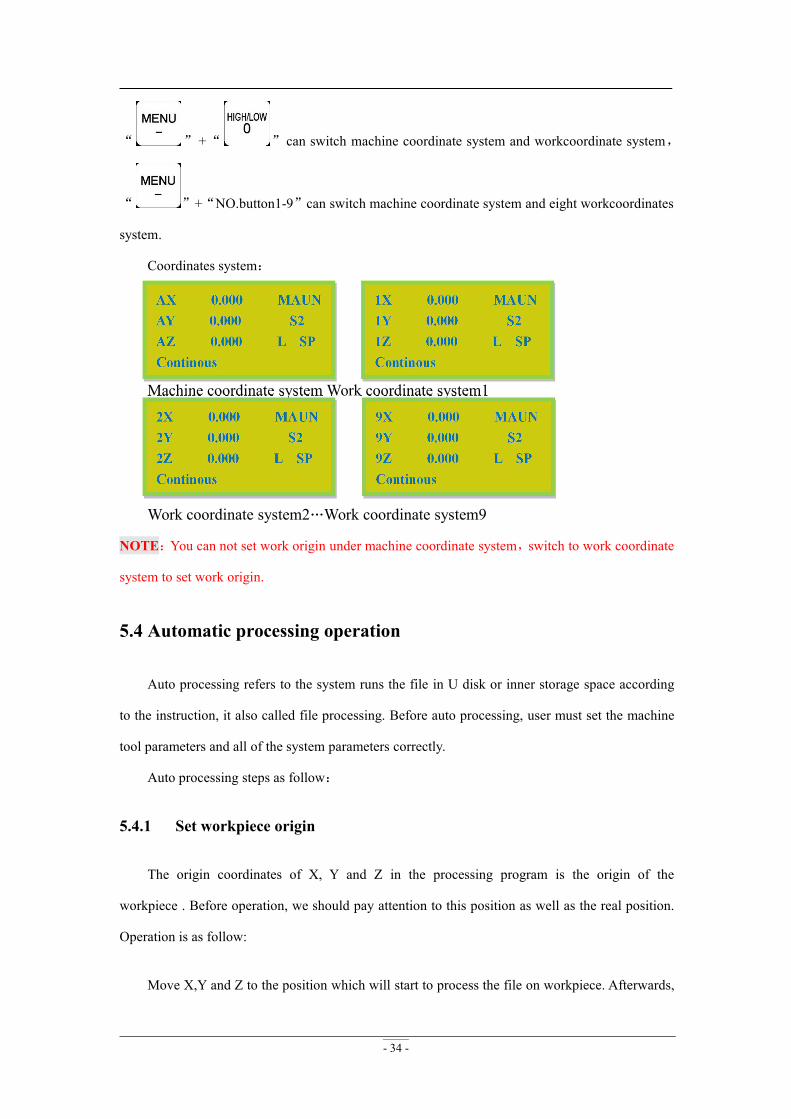
RichAuto-A1X provide a machine coordinate system and nine workcoordinates system,press
- 34 -
“ ”+“ ”can switch machine coordinate system and workcoordinate system,
“ ”+“NO.button1-9”can switch machine coordinate system and eight workcoordinates
system.
Coordinates system:
Machine coordinate system Work coordinate system1
…
Work coordinate system2…Work coordinate system9
NOTE:You can not set work origin under machine coordinate system,switch to work coordinate
system to set work origin.
5.4 Automatic processing operation
Auto processing refers to the system runs the file in U disk or inner storage space according
to the instruction, it also called file processing. Before auto processing, user must set the machine
tool parameters and all of the system parameters correctly.
Auto processing steps as follow:
5.4.1 Set workpiece origin
The origin coordinates of X, Y and Z in the processing program is the origin of the
workpiece . Before operation, we should pay attention to this position as well as the real position.
Operation is as follow:
Move X,Y and Z to the position which will start to process the file on workpiece. Afterwards,
- 35 -
press zero clearing “ ” can set the origin of X,Y axis. Press zero clearing “ ” to set
the origin of Z axis. It should be noted that if user have already used the tool setting function
which combination button is “ ”+“ ”, will no need to press the “ ” button.
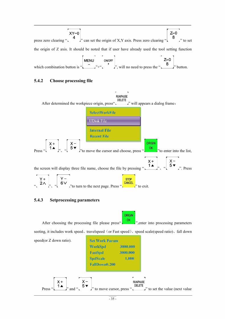
5.4.2 Choose processing file
After determined the workpiece origin, press“ ” will appears a dialog frame:
Press “ ”、“ ”to move the cursor and choose, press “ ”to enter into the list,
the screen will display three file name, choose the file by pressing “ ”、“ ”. Press
“ ”、“ ”to turn to the next page. Press “ ” to exit.
5.4.3 Setprocessing parameters
After choosing the processing file please press“ ”,enter into processing parameters
seeting, it includes work speed、travelspeed(or Fast speed)、speed scale(speed ratio)、fall down
speed(or Z down ratio).
Press “ ” and “ ” to move cursor, press “ ” to set the value (next value
- 36 -
setting is the same as this one), then pess “ ” to save, the system will check the processing
code and start to process when checking finished.
The system code checking is auto mode, user can press “ ” to skip the checking and
start ruuning file immidiately.
System will remenber the checking only when the previous checking is a complete and
correct checking.So that the system will not check the same code again next time.
In the process of processing, the screen scrolling display real-time processing
speed,operationtime,current line number. We can switch these options by pressing “ ”.
5.5 Operations during processing
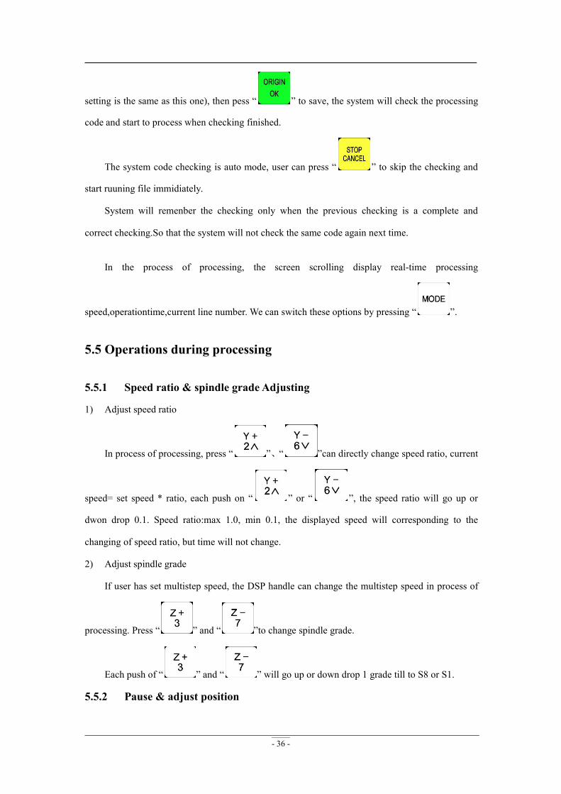
5.5.1 Speed ratio & spindle grade Adjusting
1) Adjust speed ratio
In process of processing, press “ ”、“ ”can directly change speed ratio, current
speed= set speed * ratio, each push on “ ” or “ ”, the speed ratio will go up or
dwon drop 0.1. Speed ratio:max 1.0, min 0.1, the displayed speed will corresponding to the
changing of speed ratio, but time will not change.
2) Adjust spindle grade
If user has set multistep speed, the DSP handle can change the multistep speed in process of
processing. Press “ ” and “ ”to change spindle grade.
Each push of “ ” and “ ” will go up or down drop 1 grade till to S8 or S1.
5.5.2 Pause & adjust position

- 37 -
Press “ ” pause processing. The right upwards of screen will change from“MAUN”
to “PAUZ”and machine paused processing except the rotating of spindle. Shown below:
At this moment, the user is allowed to adjust the position of X,Y and Z axis. The system
default motion mode is STEP. So that user can fine adjust each axis distance. Machine moves one
low or high speed grid distance every step. Meanwhile, user can change the speed mode to high
mode just press “ ”.
When the adjustment is finished, press “ ” again, screen shows below:
The system asks the user whether save the modified position. Press “ ”/ “ ”
the system will start processing in modified position, press “ ”, system will back to the
position before modifying.
5.5.3 Breakpoint processing & power down protection
1) Breakpoint processing
If user presses “ ” during process of processing, the screen shows below:
If we want to save breakpoint, press “ ”,the screen displays break list(totally 8), press
- 38 -
“ ”、“ ”to choose the save position and then press “ ” to save, system auto
go to standard interface. If we want to continue processing from the breakpoint, we can choose the
combination button “ ” + “1-8”. First press “ ” and not release it, at the same
time press number button(1-8), then release together, the system will start processing from the
breakpoint.
For example: You want to start processing from the breakpoint 1, then you should use the
combination button “ ” + “1”, system will restore processing from breakpoint 1. The
screen shows below:
If you want to go backwards from this breakpoint, press “ ”and input the line No.,
and then press “ ”, system will work from the new line number.
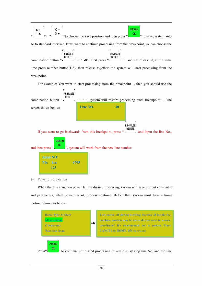
2) Power off protection
When there is a sudden power failure during processing, system will save current coordinate
and parameters, while power restart, process continue. Before that, system must have a home
motion. Shown as below:
Press“ ”to continue unfinished processing, it will display stop line No, and the line
- 39 -
number can be chosen. Press“ ”cancel the power off protection.
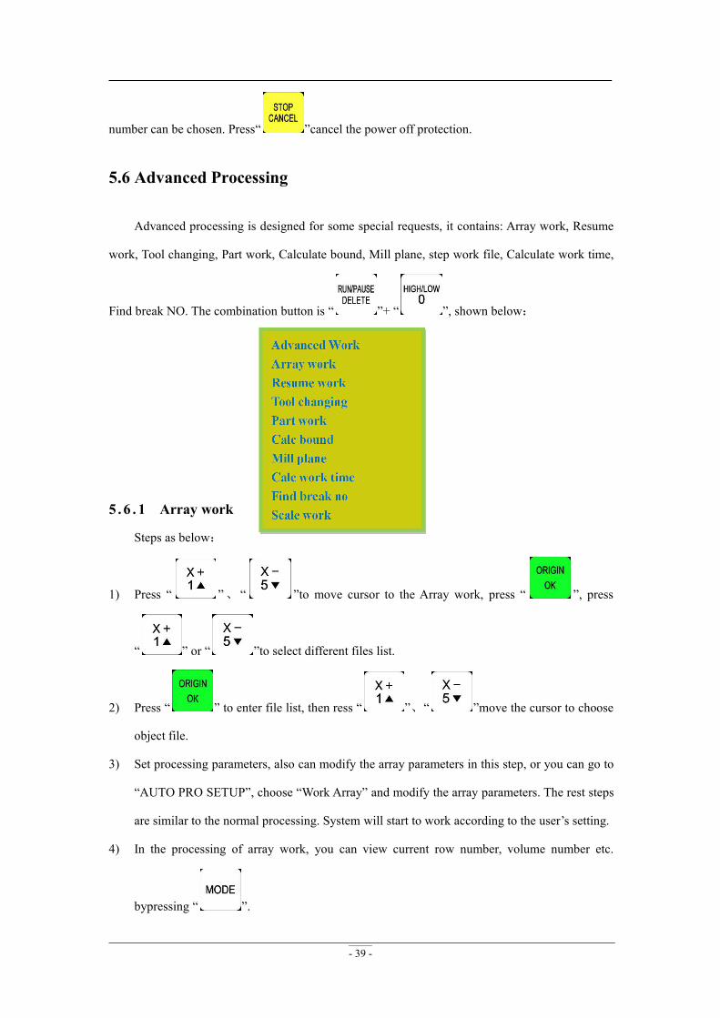
5.6 Advanced Processing
Advanced processing is designed for some special requests, it contains: Array work, Resume
work, Tool changing, Part work, Calculate bound, Mill plane, step work file, Calculate work time,
Find break NO. The combination button is “ ”+ “ ”, shown below:
5 .6 . 1 Array work
Steps as below:
1) Press “ ”、 “ ”to move cursor to the Array work, press “ ”, press
“ ” or “ ”to select different files list.
2) Press “ ” to enter file list, then ress “ ”、“ ”move the cursor to choose
object file.
3) Set processing parameters, also can modify the array parameters in this step, or you can go to
“AUTO PRO SETUP”, choose “Work Array” and modify the array parameters. The rest steps
are similar to the normal processing. System will start to work according to the user’s setting.
4) In the processing of array work, you can view current row number, volume number etc.
bypressing “ ”.
- 40 -
CAUTION:Set interval to a negative value if users want a manual control during array
processing.
5 .6 . 2 Resume work
Steps as follows:
Press “ ”、“ ” to move cursor to resume work, press “ ” to enter, then
press “ ” or “ ” to select different break points, and then press “ ”, system
will restore processing from the break point. If you want to go backwards from this breakpoint,
press “ ”and input the line No., and then press “ ”, system will work from the new
line number.Specific operation stepsin 5.5.3 breakpoint processing & power down protection.
5 .6 . 3 Tool changing
It achieve manually change the tools at the position you set. Press “ ” to enter into the
setup, and also press “ ” back to work origin.
5 .6 . 4 Part work
Park work means user can select start line and stop line, so part of the processing file can be
processed. Steps as follows:
1) Press “ ”to set, press “ ” and “ ” to move the cursor to select defferent
file list;
2) Press“ ” to enter, press “ ” and “ ” to select a file, then press
“ ”, system start to read the file.
3) After read the file, press “ ”the screen display line 1 of the code, press “ ”,
prompted “input start number: displays total lines”, input number of start line and press
- 41 -
“ ”to confirm, if input wrong number, just press “ ” to delete it.
4) Press“ ”again, to set the end line, the screen displays “input end number”,
press“ ”the screen save the changed start line number, press “ ”, Input end
line in cursor, press “ ” to confirm, press“ ” to modify.
5) Set processing parameters.
5 .6 . 5 Calculate bound
Calculate bound means user can check the size of processing, So as to avoid unnecessary
waste of materials and processing errors. Steps as below:
1) Press “ ” to enter, then press “ ” or“ ”to select file list;
2) Press “ ”get into the file list, and then press “ ” or“ ”to choose file.
3) Press “ ”, system start to read the file, after reading the file, the system will calculate
the area.
5 .6 . 6 Mill plane
Include two types: scan mill and encircle mill.
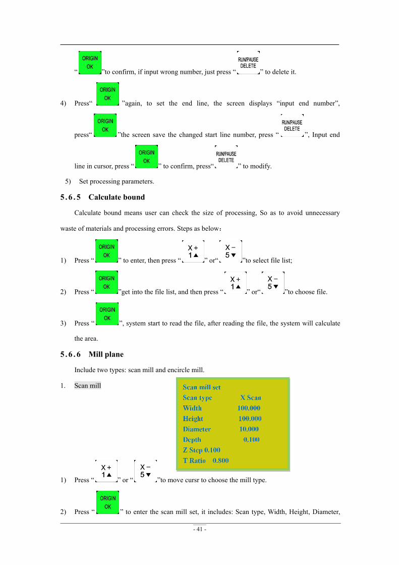
1. Scan mill
1) Press “ ” or “ ”to move cursr to choose the mill type.
2) Press “ ” to enter the scan mill set, it includes: Scan type, Width, Height, Diameter,
- 42 -
Depth, Z Step, T Ratio.
3) Press “ ” and “ ”to move cursor on the option which need modify, press
“ ” to choose mill type(X Scan or Y Scan), also press this button to modify the
parameters. Press “ ” after modified all the parameters to save them.
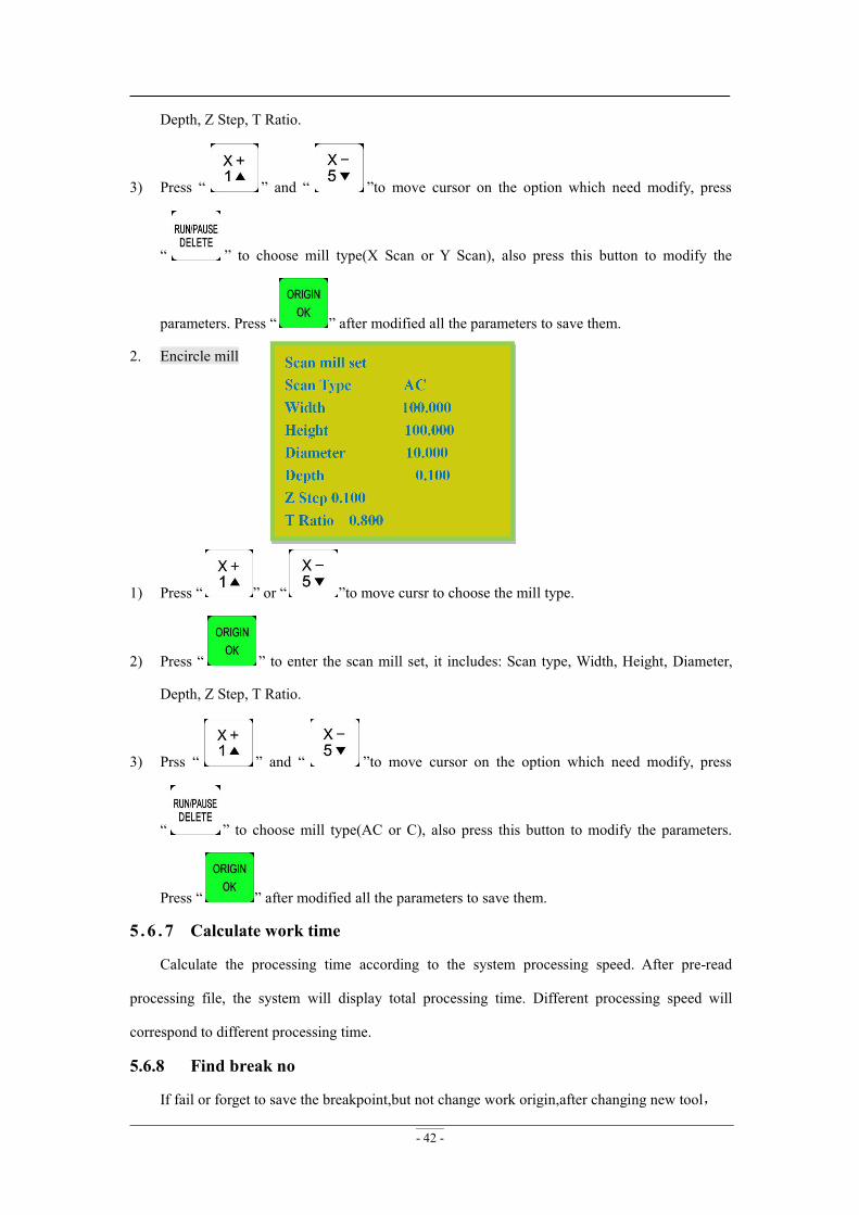
2. Encircle mill
1) Press “ ” or “ ”to move cursr to choose the mill type.
2) Press “ ” to enter the scan mill set, it includes: Scan type, Width, Height, Diameter,
Depth, Z Step, T Ratio.
3) Prss “ ” and “ ”to move cursor on the option which need modify, press
“ ” to choose mill type(AC or C), also press this button to modify the parameters.
Press “ ” after modified all the parameters to save them.
5 .6 . 7 Calculate work time
Calculate the processing time according to the system processing speed. After pre-read
processing file, the system will display total processing time. Different processing speed will
correspond to different processing time.
5.6.8 Find break no
If fail or forget to save the breakpoint,but not change work origin,after changing new tool,
- 43 -
users can choose this operation. Move X,Y axis to the processing stop position,press“ ”+
“ ”to start “Advanced Work”,and then press“ ”、“ ”to choose “Find break
no.”,press“ ”to get in,afterreading,screen shows:Press enter key to continue working from
searching position,press other key only show the line number.
Press“ ”to start processing,press“ / ”,the screen will show theline
number.
CAUTION:Work coordinate system must be same to the coordinate system which saves the
breakpoint.
Look for position line number. If accidentally cutter break and user hasn’t saved the break
point, reboot system and replace the cutter. After that, user can manually move X, Y axis to the
nearest point where the cutter was broken (recommend to move a little further), press “ ”
enter into “Find break no.”, afterwards choose the previous processing file, the system will prompt
“searching current position”. System will start processing after finished the searching, the system
will prompt “press “ ”start processing,press “ ” to view the current position of
line number”.
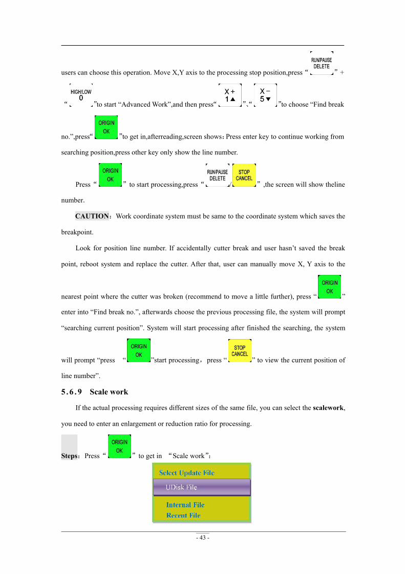
5 .6 . 9 Scale work
If the actual processing requires different sizes of the same file, you can select the scalework,
you need to enter an enlargement or reduction ratio for processing.
Steps:Press“ ”to get in “Scale work”:
- 44 -
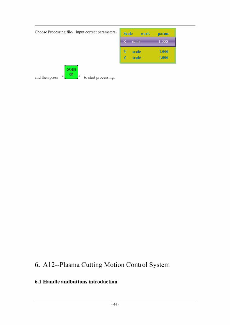
Choose Processing file,input correct parameters:
and then press “ ” to start processing.
6. A12--Plasma Cutting Motion Control System
6.1 Handle andbuttons introduction
- 45 -
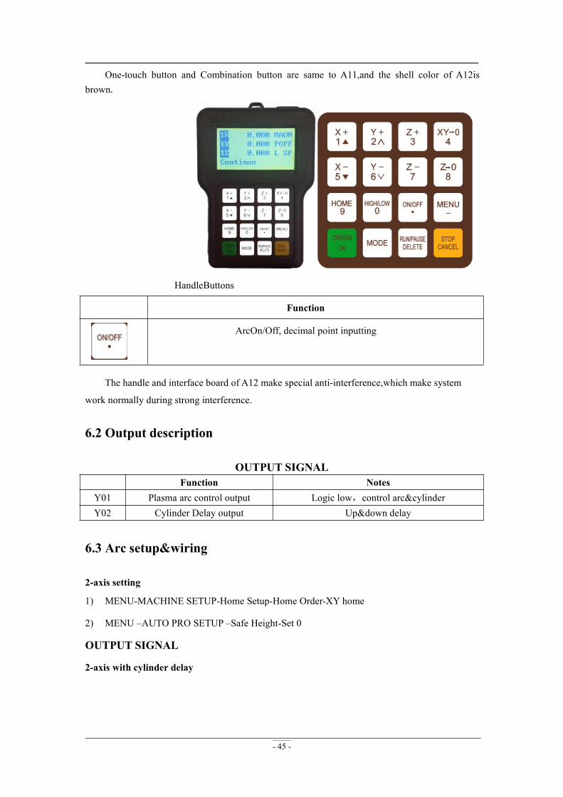
One-touch button and Combination button are same to A11,and the shell color of A12isbrown.
HandleButtons
Function
ArcOn/Off, decimal point inputting
The handle and interface board of A12 make special anti-interference,which make system
work normally during strong interference.
6.2 Output description
OUTPUT SIGNALFunction Notes
Y01 Plasma arc control output Logic low,control arc&cylinderY02 Cylinder Delay output Up&down delay
6.3 Arc setup&wiring
2-axis setting
1) MENU-MACHINE SETUP-Home Setup-Home Order-XY home
2) MENU –AUTO PRO SETUP –Safe Height-Set 0
OUTPUT SIGNAL
2-axis with cylinder delay

- 46 -
1.2-axis
2.3-axis
6.4 Parametersdescription

- 47 -
1.Axis Prohibited(MACHINE SETUP)
If it is a two-axis plasma cutting machine, users can choose to sett Z-axis disable, and all
relevant parameters about Z axis will no longer be meaningful.
2.Arc Delay(MACHINE SETUP)Unit:ms
OnDelay:How long to wait for starting plasma after reading file.
OffDelay:How long to wait for closing plasmaafter processing.
3.Cylinder Delay(MACHINE SETUP)Unit:ms
DwnDelay:How long to wait for cylinder getting down.
UpDelay:How long to wait for cylinder rising up.
4.Circle Limit (AUTO PRO SETUP)
System default 1000(not speed unit) . If small circle processing speed too fast that cause
deformation or badquality,users can reduced this value proportionately, such as 500,250,125 ...,and
it can greatly improve the quality of processing.
5.Plasma Config (AUTO PRO SETUP)
PreOnDly:How long to wait for cylinder getting down.
PreOfDly:How long to wait for cylinder rising up.
7. A15--Multi-spindle Motion Control System
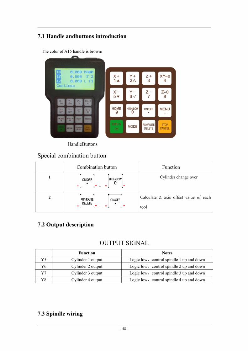
- 48 -
7.1 Handle andbuttons introduction
The color of A15 handle is brown:
HandleButtons
Special combination button
Combination button Function
1
“ ”+ “ ”
Cylinder change over
2
“ ”+ “ ”
Calculate Z axis offset value of each
tool
7.2 Output description
OUTPUT SIGNALFunction Notes
Y5 Cylinder 1 output Logic low,control spindle 1 up and downY6 Cylinder 2 output Logic low,control spindle 2 up and downY7 Cylinder 3 output Logic low,control spindle 3 up and downY8 Cylinder 4 output Logic low,control spindle 4 up and down
7.3 Spindle wiring
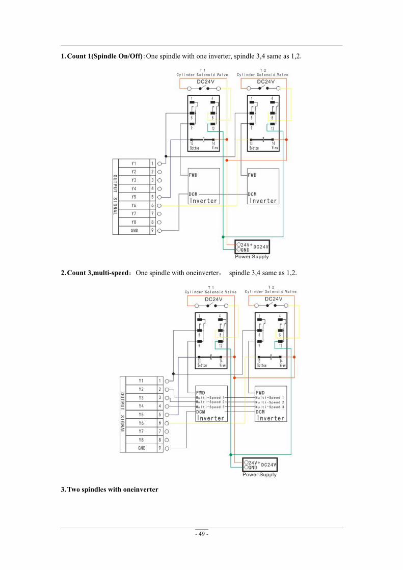
- 49 -
1.Count 1(Spindle On/Off):One spindle with one inverter, spindle 3,4 same as 1,2.
2.Count 3,multi-speed:One spindle with oneinverter, spindle 3,4 same as 1,2.
3.Two spindles with oneinverter
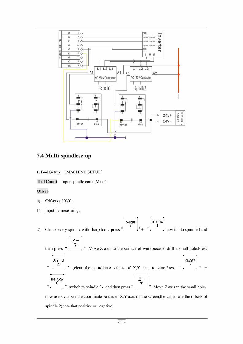
- 50 -
7.4 Multi-spindlesetup
1.Tool Setup:(MACHINE SETUP)
Tool Count:Input spindle count,Max 4.
Offset:
a) Offsets of X,Y:
1) Input by measuring.
2) Chuck every spindle with sharp tool,press“ ”+ “ ”,switch to spindle 1and
then press“ ” .Move Z axis to the surface of workpiece to drill a small hole.Press
“ ” ,clear the coordinate values of X,Y axis to zero.Press “ ” +
“ ”,switch to spindle 2,and then press“ ”.Move Z axis to the small hole,
now users can see the coordinate values of X,Y axis on the screen,the values are the offsets of
spindle 2(note that positive or negative).
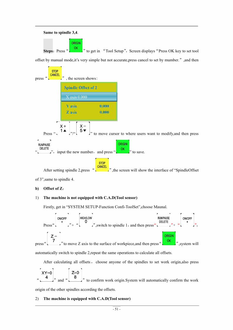
- 51 -
Same to spindle 3,4.
Steps:Press“ ”to get in “Tool Setup”,Screen displays“Press OK key to set tool
offset by manual mode,it’s very simple but not accurate,press cancel to set by mumber.”,and then
press“ ”,the screen shows:
Press “ ”/“ ” to move cursor to where users want to modify,and then press
“ ”,input the new number,and press “ ” to save.
After setting spindle 2,press“ ”,the screen will show the interface of “SpindleOffset
of 3”,same to spindle 4.
b) Offset of Z:
1) The machine is not equipped with C.A.D(Tool sensor)
Firstly, get in “SYSTEM SETUP-Function Confi-ToolSet”,choose Maunal.
Press“ ”+“ ”,switch to spindle 1,and then press“ ”+“ ”,
press“ ”to move Z axis to the surface of workpiece,and then press“ ”,system will
automatically switch to spindle 2,repeat the same operations to calculate all offsets.
After calculating all offsets, choose anyone of the spindles to set work origin,also press
“ ”and“ ”to confirm work origin.System will automatically confirm the work
origin of the other spindles according the offsets.
2) The machine is equipped with C.A.D(Tool sensor)
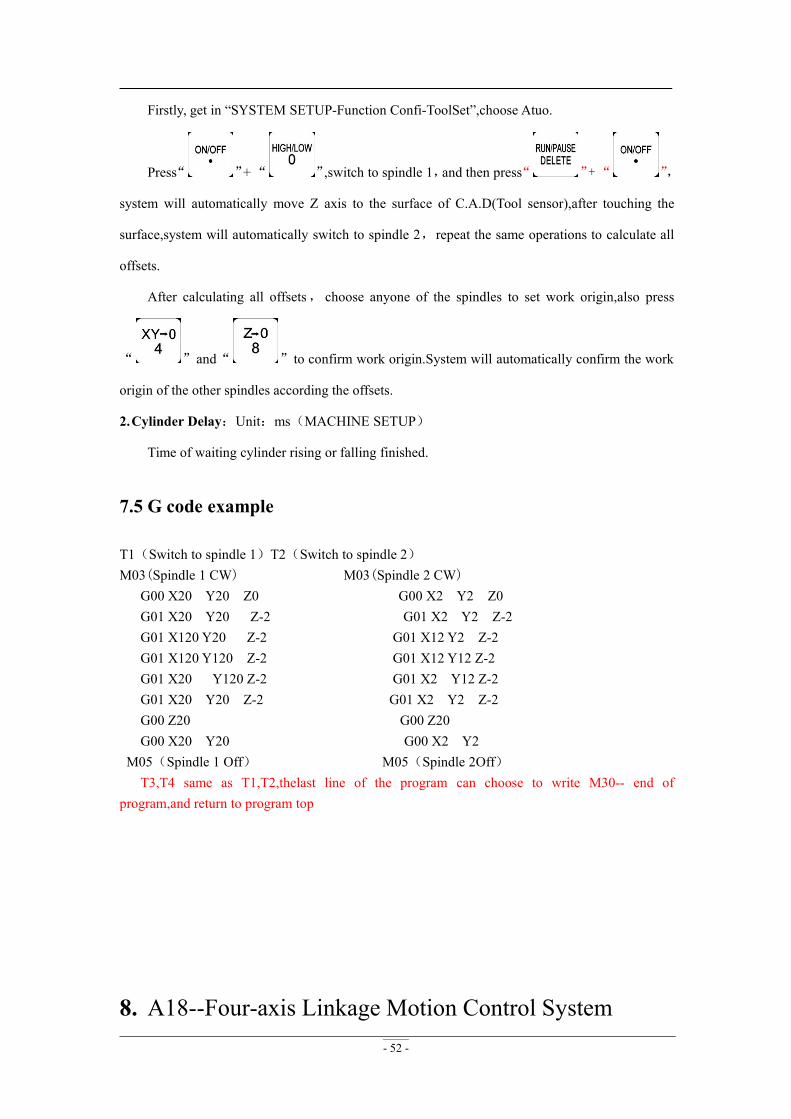
- 52 -
Firstly, get in “SYSTEM SETUP-Function Confi-ToolSet”,choose Atuo.
Press“ ”+“ ”,switch to spindle 1,and then press“ ”+“ ”,
system will automatically move Z axis to the surface of C.A.D(Tool sensor),after touching the
surface,system will automatically switch to spindle 2,repeat the same operations to calculate all
offsets.
After calculating all offsets, choose anyone of the spindles to set work origin,also press
“ ”and“ ”to confirm work origin.System will automatically confirm the work
origin of the other spindles according the offsets.
2.Cylinder Delay:Unit:ms(MACHINE SETUP)
Time of waiting cylinder rising or falling finished.
7.5 G code example
T1(Switch to spindle 1)T2(Switch to spindle 2)M03(Spindle 1 CW) M03(Spindle 2 CW)
G00 X20 Y20 Z0 G00 X2 Y2 Z0G01 X20 Y20 Z-2 G01 X2 Y2 Z-2G01 X120 Y20 Z-2 G01 X12 Y2 Z-2G01 X120 Y120 Z-2 G01 X12 Y12 Z-2G01 X20 Y120 Z-2 G01 X2 Y12 Z-2G01 X20 Y20 Z-2 G01 X2 Y2 Z-2G00 Z20 G00 Z20G00 X20 Y20 G00 X2 Y2
M05(Spindle 1 Off) M05(Spindle 2Off)T3,T4 same as T1,T2,thelast line of the program can choose to write M30-- end of
program,and return to program top
8. A18--Four-axis Linkage Motion Control System
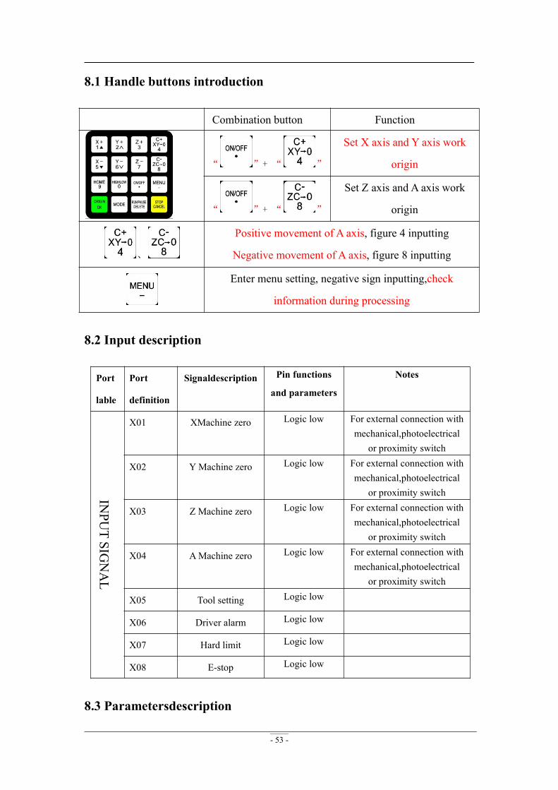
- 53 -
8.1 Handle buttons introduction
Combination button Function
“ ”+ “ ”
Set X axis and Y axis work
origin
“ ”+ “ ”
Set Z axis and A axis work
origin
、
Positive movement of A axis, figure 4 inputting
Negative movement of A axis, figure 8 inputting
Enter menu setting, negative sign inputting,check
information during processing
8.2 Input description
Port
lable
Port
definition
Signaldescription Pin functions
and parameters
Notes
INPU
TSIG
NAL
X01 XMachine zero Logic low For external connection withmechanical,photoelectrical
or proximity switch
X02 YMachine zero Logic low For external connection withmechanical,photoelectrical
or proximity switch
X03 Z Machine zero Logic low For external connection withmechanical,photoelectrical
or proximity switch
X04 AMachine zero Logic low For external connection withmechanical,photoelectrical
or proximity switch
X05 Tool setting Logic low
X06 Driver alarm Logic low
X07 Hard limit Logic low
X08 E-stop Logic low
8.3 Parametersdescription
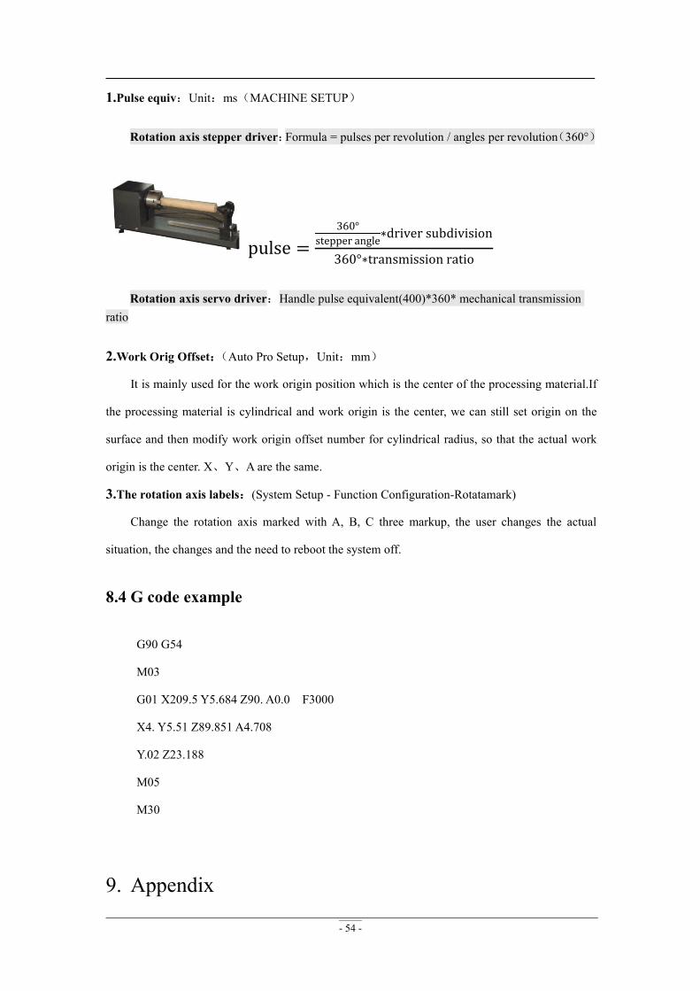
- 54 -
1.Pulse equiv:Unit:ms(MACHINE SETUP)
Rotation axis stepper driver:Formula = pulses per revolution / angles per revolution(360°)
pulse =360°
stepper angle∗driver subdivision
360°∗transmission ratio
Rotation axis servo driver:Handle pulse equivalent(400)*360* mechanical transmissionratio
2.Work Orig Offset:(Auto Pro Setup,Unit:mm)
It is mainly used for the work origin position which is the center of the processing material.If
the processing material is cylindrical and work origin is the center, we can still set origin on the
surface and then modify work origin offset number for cylindrical radius, so that the actual work
origin is the center. X、Y、A are the same.
3.The rotation axis labels:(System Setup - Function Configuration-Rotatamark)
Change the rotation axis marked with A, B, C three markup, the user changes the actual
situation, the changes and the need to reboot the system off.
8.4 G code example
G90 G54
M03
G01 X209.5 Y5.684 Z90. A0.0 F3000
X4. Y5.51 Z89.851 A4.708
Y.02 Z23.188
M05
M30
9. Appendix
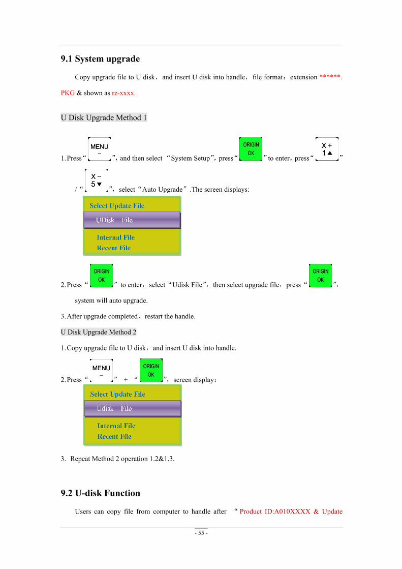
- 55 -
9.1 System upgrade
Copy upgrade file to U disk,and insert U disk into handle,file format:extension ******.
PKG & shown as rz-xxxx.
U Disk Upgrade Method 1
1.Press“ ”,and then select“System Setup”,press“ ”to enter,press“ ”
/“ ”,select“Auto Upgrade”.The screen displays:
2.Press“ ”to enter,select“Udisk File”,then select upgrade file,press“ ”,
system will auto upgrade.
3.After upgrade completed,restart the handle.
U Disk Upgrade Method 2
1.Copy upgrade file to U disk,and insert U disk into handle.
2.Press“ ” + “ ”,screen display:
3. Repeat Method 2 operation 1.2&1.3.
9.2 U-disk Function
Users can copy file from computer to handle after “ Product ID:A010XXXX & Update

- 56 -
Version rz-1967 ” version. Connect handle and computer by USB cable, users can find
portable storage device on the computer , and then copy processing files from computer to
handle inner. This function can insure that if USB port of the handle is broken or there is no U
disk ,the machine can still work normally.
Steps:
4.Press any two buttons at the same time(for example:“ ”+“ ”).
5.Connect handle and computer by USB cable,it means that the handle is powered by computer,
loosen the buttons after the power supply.
6.Handle screen displays:
Connect successfully.
7.Open“My Computer”,and you will find portable storage device:
A0101203(H:) :Handle,Users can copy processing files to handle inner.
8.Connect handle and machine,Choose internal file to start processing.
NOTE:Users can check hardware type in Version View:“FlashDiskMode” is necessary ornot ,if not, users can not copy processing files from computer to handle inner.
9.3 Servo driver parameters9.3.1 YASKAWA Σ-7、Σ-Ⅴ1.Wiring diagram(Y、Z same as X)Set PnA=8170,do not connect pin-40
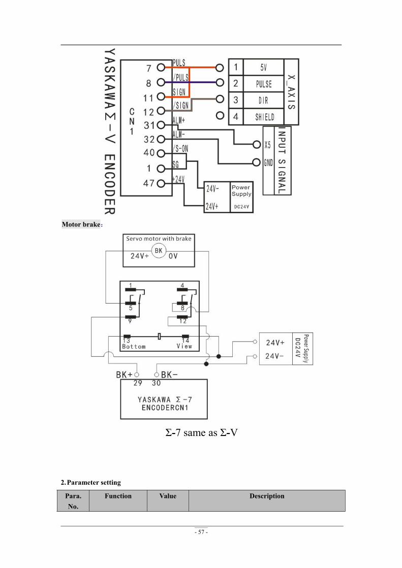
- 57 -
Motor brake:
Σ-7 same as Σ-Ⅴ
2.Parameter setting
Para.No.
Function Value Description

- 58 -
*Pn000 Functionselection basicswitch 0
0010 Bit 0: Set 0,positive rotation at positive rotationcommandBit 1:Set 1,position control mode(pulse sequencecommand)
*Pn200 Format seletionswitch ofposition controlcommand
0005 Bit 0 : Set 5,select the instruction mode as“pulse+direction”,negative logic
*Pn20E Electronic gearratio(numerator)
Needcalculation
Pn20E=Encoder resolution
Pn210=Pulse equivalent×Screwpitch×Transmission
ratio
e.g. Pulse equivalent 1000 , Screw pitch10mm,Encoder 20-bit,Transmission ratio1Pn20E/Pn210=220/1000×10×1=1048576/10000
=131072/625
*Pn210 Electronic gearratio(denominator)
Needcalculation
*Pn50A Input signalselection 1
8170 Bit 1:Set 7,servo on all the time.Bit 3: Set8,positive rotation not used and signalinput(P-OT)prohibited
*Pn50F Output signalselection 2
0300 Set it when servo motor with brakes.Bit 2:Set 3,brake interlock signal “/BK”is outputfrom CN1-29,CN1-30 to control 24V relay used forbrake
*Pn50E Output signalselection 1
0211 Set it when servo motor with brakes.To avoid of CN1-29 and CN1-30 being used forother function and leading to brake ineffective,3 isnot allowed to appear in the 4 digits.
NOTES:1.
… Bit2 Bit1 Bit0… 0 0 0
The same below.2. For parameters which No. have a suffix of "*", changed contents will be validated when youturn on thecontrol power.The same below.
3. ALM+ : pin-31 , ALM- : pin-32,normally closed. The default alarm input terminal ofA11,A12,A15 is X5,A18 is X6.
Machine Setup-Voltage Setup,modify level of X5(X6-A18) normally closed(Press“ ”
changhe direction of the arrow facing up)The same below.
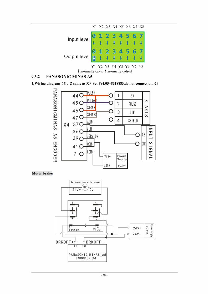
- 59 -
↓:normally open,↑:normally colsed9.3.2 PANASONIC MINAS A51.Wiring diagram(Y、Z same as X)Set Pr4.05=8618883,do not connect pin-29
Motor brake:

- 60 -
2.Parameter setting
Para.No.
Function Value Description
*Pr0.00 Settingthe directionof rotation
0 If the motor rotation direction opposite to theactual needs, set 1.
*Pr0.01 Select control mode 0 0:Position mode,1:velocity mode,2:torque mode
*Pr0.05Selection ofcommand pulse input 0
0:Photo-coupler input(PULS1,PULS2,SIGN1,SIGN2)
1:Exclusive input for line driver(PULSH1,PULSH2,SIGNH1,SIGNH2)
*Pr0.07 Command pulse inputmode setup
3 Set command pulse inputmode:commandpulse+commanddirection,negativeligic.
*Pr0.08 Command pulse No.per motor circle
0 When it is set to “0”,parameters Pr0.09 andPr0.10 are valid
Pr0.09
1st numerator ofcommand pulsefrequencymultiplication
Needcalculatio
nRange:0~
230
Z1 = Encoder resolution
Z2 = Pulse equivalent×Screwpitch×Transmission
ratio
e.g. Pulse equivalent 1000,Screw pitch 10mm,Encoder resolution 10000,Transmission ratio 1Z1/Z2= 10000/1000×10×1=1/1
set Pr0.09=1,set Pr0.10=1.The value of Pr0.09
and Pr0.10 must be integer,range: 0~230.Pr0.10
Denominator of thecommand pulsefrequencymultiplication
Needcalculatio
nRange:0~
230
*Pr4.05 Function setting fordigital input pin SI6
8618883 Bit1,0:Set 83,servo on all the time.
NOTES:1. ALM+:pin-37,ALM-:pin-36,normally closed.
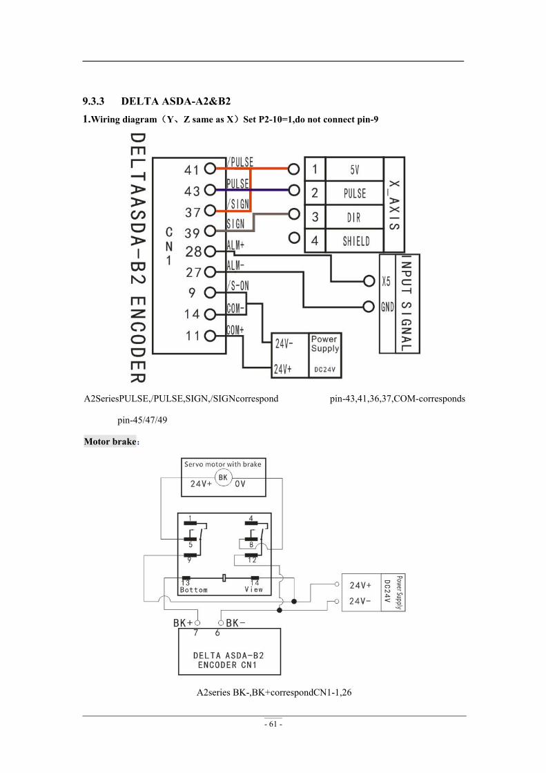
- 61 -
9.3.3 DELTA ASDA-A2&B21.Wiring diagram(Y、Z same as X)Set P2-10=1,do not connect pin-9
A2SeriesPULSE,/PULSE,SIGN,/SIGNcorrespond pin-43,41,36,37,COM-corresponds
pin-45/47/49
Motor brake:
A2series BK-,BK+correspondCN1-1,26
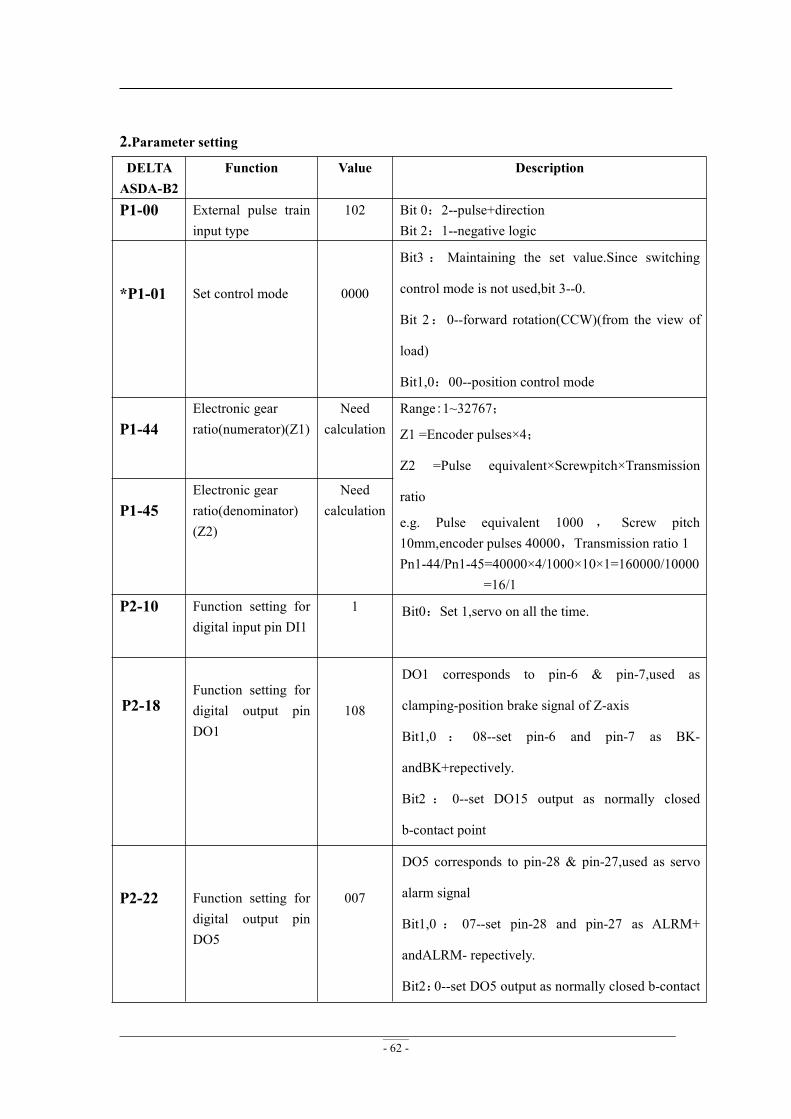
- 62 -
2.Parameter settingDELTAASDA-B2
Function Value Description
P1-00 External pulse traininput type
102 Bit 0:2--pulse+directionBit 2:1--negative logic
*P1-01 Set control mode 0000
Bit3 : Maintaining the set value.Since switching
control mode is not used,bit 3--0.
Bit 2:0--forward rotation(CCW)(from the view of
load)
Bit1,0:00--position control mode
P1-44Electronic gearratio(numerator)(Z1)
Needcalculation
Range:1~32767;
Z1 =Encoder pulses×4;
Z2 =Pulse equivalent×Screwpitch×Transmission
ratio
e.g. Pulse equivalent 1000 , Screw pitch10mm,encoder pulses 40000,Transmission ratio 1Pn1-44/Pn1-45=40000×4/1000×10×1=160000/10000
=16/1
P1-45Electronic gearratio(denominator)(Z2)
Needcalculation
P2-10 Function setting fordigital input pin DI1
1 Bit0:Set 1,servo on all the time.
P2-18Function setting fordigital output pinDO1
108
DO1 corresponds to pin-6 & pin-7,used as
clamping-position brake signal of Z-axis
Bit1,0 : 08--set pin-6 and pin-7 as BK-
andBK+repectively.
Bit2 : 0--set DO15 output as normally closed
b-contact point
P2-22 Function setting fordigital output pinDO5
007
DO5 corresponds to pin-28 & pin-27,used as servo
alarm signal
Bit1,0 : 07--set pin-28 and pin-27 as ALRM+
andALRM- repectively.
Bit2:0--set DO5 output as normally closed b-contact
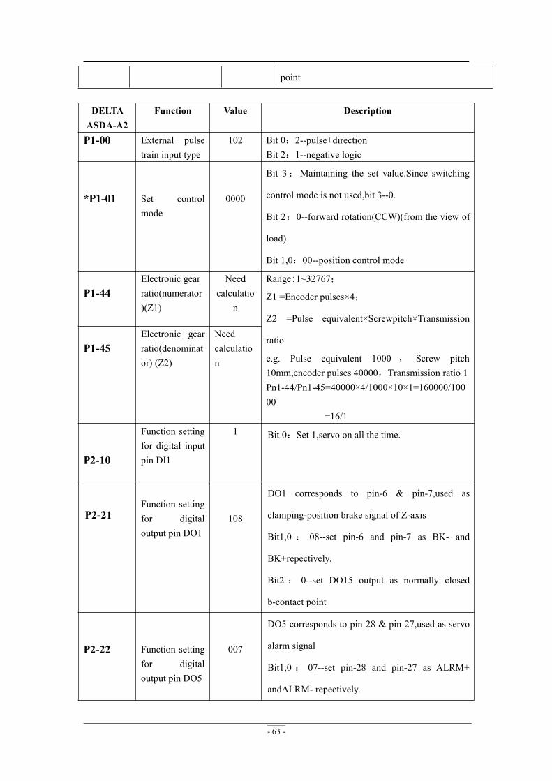
- 63 -
point
DELTAASDA-A2
Function Value Description
P1-00 External pulsetrain input type
102 Bit 0:2--pulse+directionBit 2:1--negative logic
*P1-01 Set controlmode
0000
Bit 3:Maintaining the set value.Since switching
control mode is not used,bit 3--0.
Bit 2:0--forward rotation(CCW)(from the view of
load)
Bit 1,0:00--position control mode
P1-44Electronic gearratio(numerator)(Z1)
Needcalculatio
n
Range:1~32767;
Z1 =Encoder pulses×4;
Z2 =Pulse equivalent×Screwpitch×Transmission
ratio
e.g. Pulse equivalent 1000 , Screw pitch10mm,encoder pulses 40000,Transmission ratio 1Pn1-44/Pn1-45=40000×4/1000×10×1=160000/10000
=16/1
P1-45Electronic gearratio(denominator) (Z2)
Needcalculation
P2-10
Function settingfor digital inputpin DI1
1 Bit 0:Set 1,servo on all the time.
P2-21Function settingfor digitaloutput pin DO1
108
DO1 corresponds to pin-6 & pin-7,used as
clamping-position brake signal of Z-axis
Bit1,0 : 08--set pin-6 and pin-7 as BK- and
BK+repectively.
Bit2 : 0--set DO15 output as normally closed
b-contact point
P2-22 Function settingfor digitaloutput pin DO5
007
DO5 corresponds to pin-28 & pin-27,used as servo
alarm signal
Bit1,0 : 07--set pin-28 and pin-27 as ALRM+
andALRM- repectively.
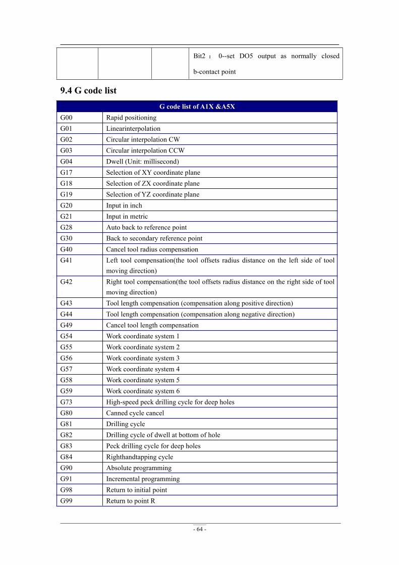
- 64 -
Bit2 : 0--set DO5 output as normally closed
b-contact point
9.4 G code listG code list of A1X &A5X
G00 Rapid positioningG01 LinearinterpolationG02 Circular interpolation CWG03 Circular interpolation CCWG04 Dwell (Unit: millisecond)G17 Selection of XY coordinate planeG18 Selection of ZX coordinate planeG19 Selection of YZ coordinate planeG20 Input in inchG21 Input in metricG28 Auto back to reference pointG30 Back to secondary reference pointG40 Cancel tool radius compensationG41 Left tool compensation(the tool offsets radius distance on the left side of tool
moving direction)G42 Right tool compensation(the tool offsets radius distance on the right side of tool
moving direction)G43 Tool length compensation (compensation along positive direction)G44 Tool length compensation (compensation along negative direction)G49 Cancel tool length compensationG54 Work coordinate system 1G55 Work coordinate system 2G56 Work coordinate system 3G57 Work coordinate system 4G58 Work coordinate system 5G59 Work coordinate system 6G73 High-speed peck drilling cycle for deep holesG80 Canned cycle cancelG81 Drilling cycleG82 Drilling cycle of dwell at bottom of holeG83 Peck drilling cycle for deep holesG84 Righthandtapping cycleG90 Absolute programmingG91 Incremental programmingG98 Return to initial pointG99 Return to point R

- 65 -
G101 Move with processing speed until the signal is triggered.Meanwhile Rollbackand pinpoint signal edge (similar to backing home)
G102 Move with fast speed until the signal is triggered.Meanwhile Rollback andpinpoint signal edge (similar to backing home)
G103 Move with processing speed until the signal is triggered.G104 Move with fast speed until the signal is triggered.M03 Spindle on(CW rotation)M04 Spindle on(CCW rotation)M05 Spindle stopM06 Tool changeM08 Coolant on (Flood)M09 Coolant offM30 End of program,and return to program topM37 Spindle on(CW rotation)M38 Spindle on(CCW rotation)M129 4th spindle onM208 Cycle machiningM210 Set outputlogic low levelM211 Set outputlogic high levelM214 Run the next line ofG codeafter waiting for the specified input signallogic lowM215 Run the next line ofG codeafter waiting for the specified input signallogic highM216 Run the next line ofG code after waiting until all the specified input signal
logichighM217 Run the next line ofG code after waiting until anyone of all the specified input
signal logic highM220 Set Y1 logic low levelM221 Set Y1 logic high levelM222 Set Y2 logic low levelM223 Set Y2 logic high levelM224 Set Y3 logic low levelM225 Set Y3 logic high levelM226 Set Y4 logic low levelM227 Set Y4 logic high levelM350 Set the extension output logic low levelM351 Set the extension output logic high levelT Tool functionS Spindle speedF FeedrateH Tool length offset
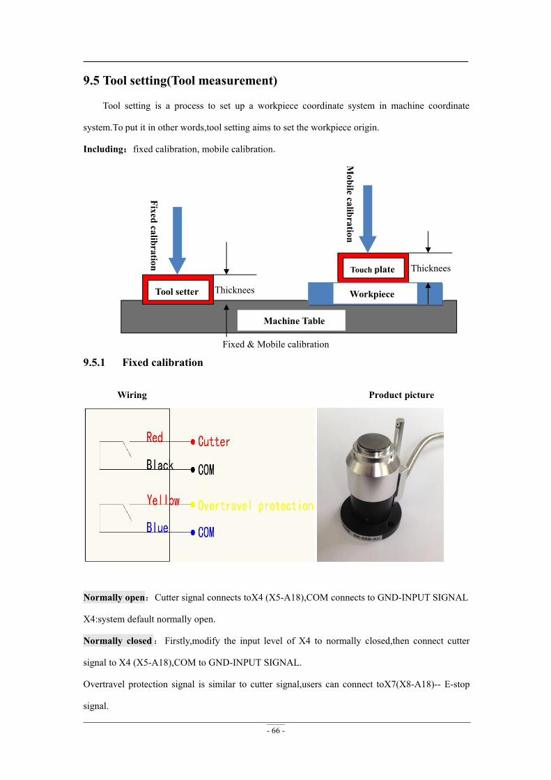
- 66 -
9.5 Tool setting(Tool measurement)
Tool setting is a process to set up a workpiece coordinate system in machine coordinate
system.To put it in other words,tool setting aims to set the workpiece origin.
Including:fixed calibration, mobile calibration.
Fixed & Mobile calibration
9.5.1 Fixed calibration
Wiring Product picture
Normally open:Cutter signal connects toX4 (X5-A18),COM connects to GND-INPUT SIGNAL
X4:system default normally open.
Normally closed:Firstly,modify the input level of X4 to normally closed,then connect cutter
signal to X4 (X5-A18),COM to GND-INPUT SIGNAL.
Overtravel protection signal is similar to cutter signal,users can connect toX7(X8-A18)-- E-stop
signal.
Machine Table
Tool setter
Touch plate
WorkpieceThicknees
Thicknees
Fixedcalibration
Mobile
calibration
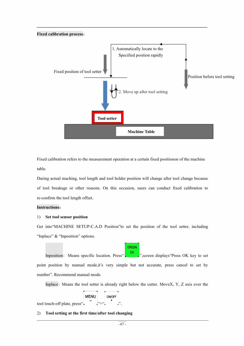
- 67 -
Fixed calibration process:
2. Move up after tool setting
Fixed calibration refers to the measurement operation at a certain fixed positionon of the machine
table.
During actual maching, tool length and tool holder position will change after tool change because
of tool breakage or other reasons. On this occasion, users can conduct fixed calibration to
re-confirm the tool length offset.
Instructions:
1) Set tool sensor position
Get into“MACHINE SETUP-C.A.D Position”to set the position of the tool setter, including
“Inplace” & “Inposition” options.
Inposition: Means specific location. Press“ ”,screen displays“Press OK key to set
point position by manual mode,it’s very simple but not accurate, press cancel to set by
number”.Recommend manual mode.
Inplace: Means the tool setter is already right below the cutter. MoveX, Y, Z axis over the
tool touch-off plate, press“ ”+“ ”.
2) Tool setting at the first time/after tool changing
Position before tool setting
Machine Table
Tool setter
Fixed position of tool setter
1. Automatically locate to theSpecified position rapidly
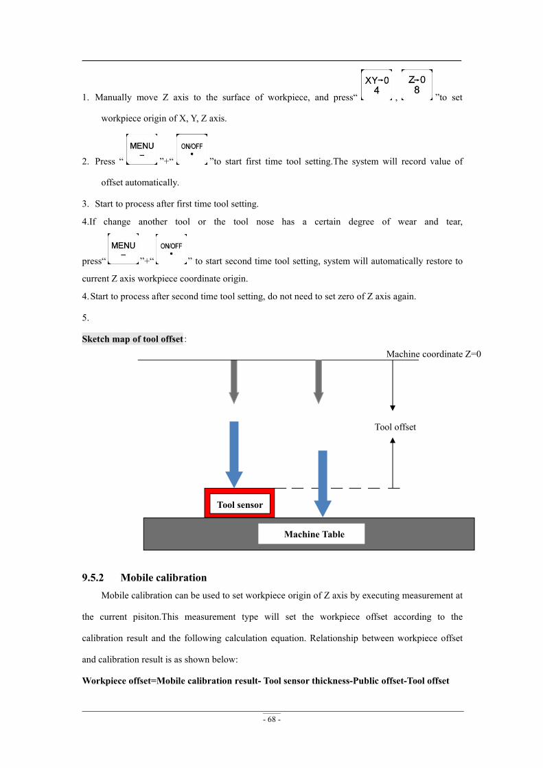
- 68 -
1. Manually move Z axis to the surface of workpiece, and press“ , ”to set
workpiece origin of X, Y, Z axis.
2. Press “ ”+“ ”to start first time tool setting.The system will record value of
offset automatically.
3. Start to process after first time tool setting.
4.If change another tool or the tool nose has a certain degree of wear and tear,
press“ ”+“ ” to start second time tool setting, system will automatically restore to
current Z axis workpiece coordinate origin.
4.Start to process after second time tool setting, do not need to set zero of Z axis again.
5.
Sketch map of tool offset:
9.5.2 Mobile calibrationMobile calibration can be used to set workpiece origin of Z axis by executing measurement at
the current pisiton.This measurement type will set the workpiece offset according to the
calibration result and the following calculation equation. Relationship between workpiece offset
and calibration result is as shown below:
Workpiece offset=Mobile calibration result- Tool sensor thickness-Public offset-Tool offset
Tool offset
Machine Table
Tool sensor
Machine coordinate Z=0
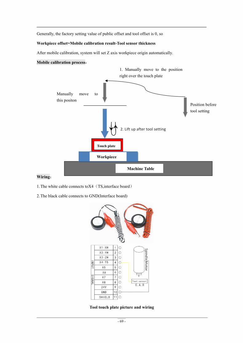
- 69 -
Generally, the factory setting value of public offset and tool offset is 0, so
Workpiece offset=Mobile calibration result-Tool sensor thickness
After mobile calibration, system will set Z axis workpiece origin automatically.
Mobile calibration process:
2. Lift up after tool setting
Wiring:
1.The white cable connects toX4(TS,interface board)
2.The black cable connects to GND(Interface board)
Tool touch plate picture and wiring
Position beforetool setting
Machine Table
Touch plate
1. Manually move to the positionright over the touch plate
Manually move tothis positon
Workpiece
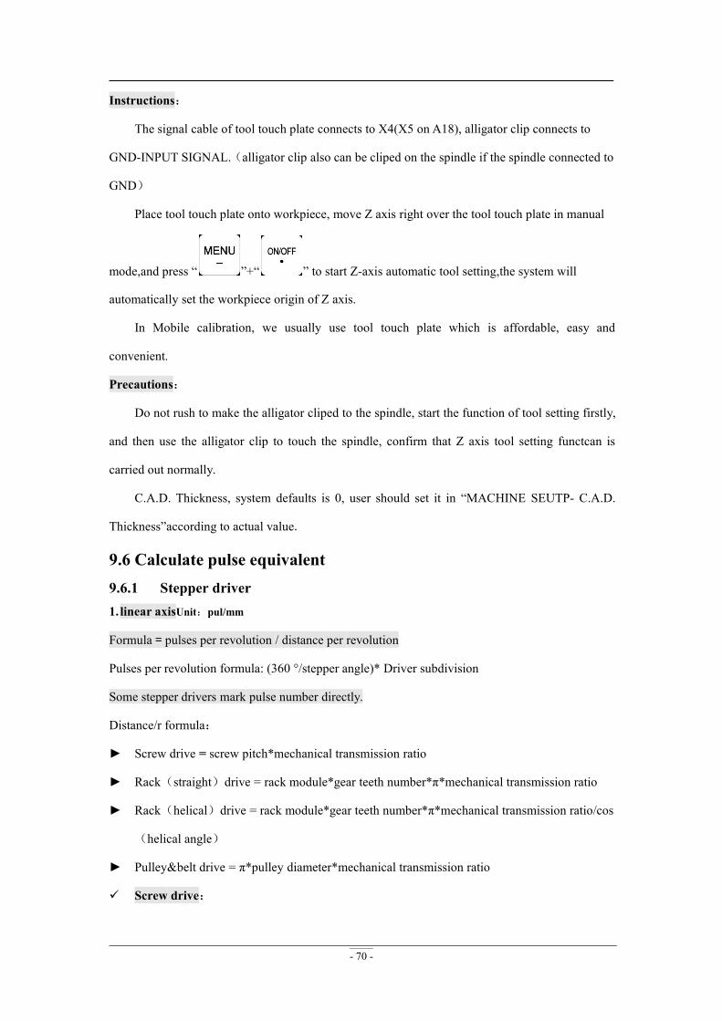
- 70 -
Instructions:
The signal cable of tool touch plate connects to X4(X5 on A18), alligator clip connects to
GND-INPUT SIGNAL.(alligator clip also can be cliped on the spindle if the spindle connected to
GND)
Place tool touch plate onto workpiece, move Z axis right over the tool touch plate in manual
mode,and press “ ”+“ ” to start Z-axis automatic tool setting,the system will
automatically set the workpiece origin of Z axis.
In Mobile calibration, we usually use tool touch plate which is affordable, easy and
convenient.
Precautions:
Do not rush to make the alligator cliped to the spindle, start the function of tool setting firstly,
and then use the alligator clip to touch the spindle, confirm that Z axis tool setting functcan is
carried out normally.
C.A.D. Thickness, system defaults is 0, user should set it in “MACHINE SEUTP- C.A.D.
Thickness”according to actual value.
9.6 Calculate pulse equivalent9.6.1 Stepper driver1. linear axisUnit:pul/mm
Formula = pulses per revolution / distance per revolution
Pulses per revolution formula: (360 °/stepper angle)* Driver subdivision
Some stepper drivers mark pulse number directly.
Distance/r formula:
► Screw drive = screw pitch*mechanical transmission ratio
► Rack(straight)drive = rack module*gear teeth number*π*mechanical transmission ratio
► Rack(helical)drive = rack module*gear teeth number*π*mechanical transmission ratio/cos
(helical angle)
► Pulley&belt drive = π*pulley diameter*mechanical transmission ratio
Screw drive:
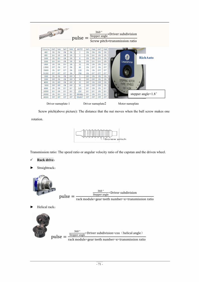
- 71 -
pulse =360 °
Stepper angle∗Driver subdivision
Screw pitch∗transmission ratio
Driver nameplate 1 Driver nameplate2 Motor nameplate
Screw pitch(above picture): The distance that the nut moves when the ball screw makes one
rotation.
Transmission ratio: The speed ratio or angular velocity ratio of the capstan and the driven wheel.
Rack drive:
► Straightrack:
pulse =360 °
Stepper angle×Driver subdivision
rack module×gear teeth number×π×transmission ratio
► Helical rack:
pulse =360 °
Stepper angle×Driver subdivision×cos(helical angle)
rack module×gear teeth number×π×transmission ratio
stepper angle=1.8°
RichAuto
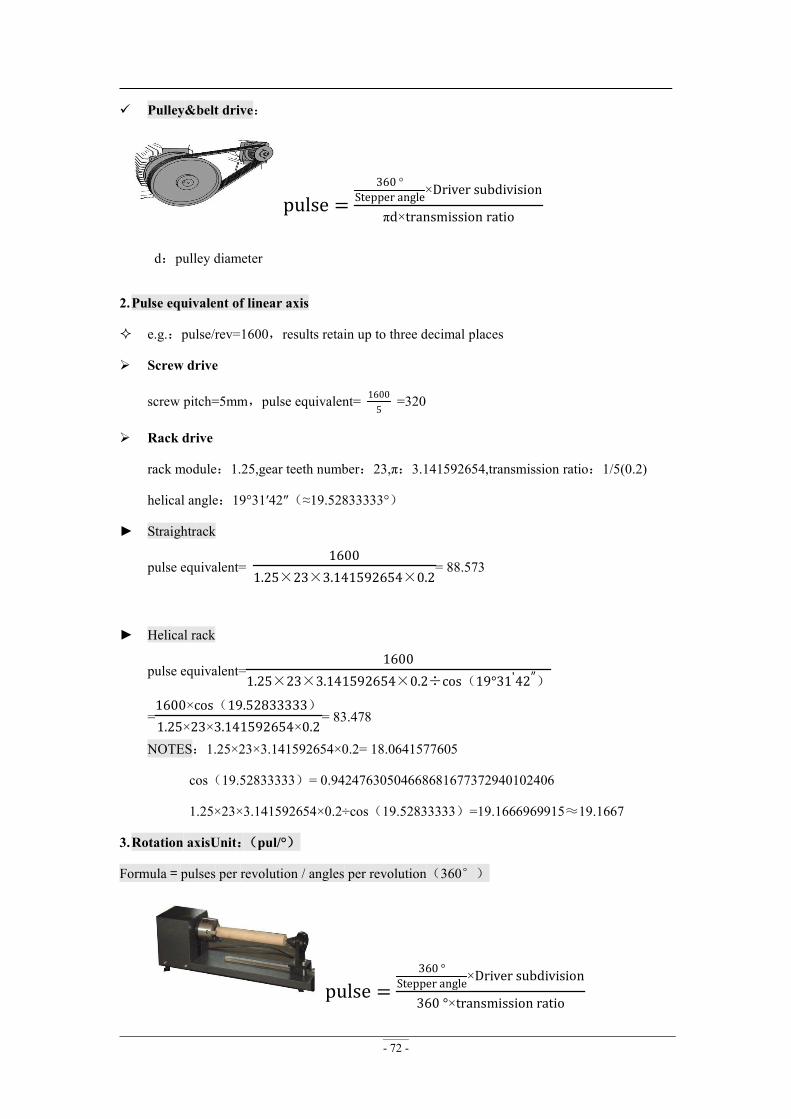
- 72 -
Pulley&belt drive:
pulse =360 °
Stepper angle×Driver subdivision
πd×transmission ratio
d:pulley diameter
2.Pulse equivalent of linear axis
e.g.:pulse/rev=1600,results retain up to three decimal places
Screw drive
screw pitch=5mm,pulse equivalent= 16005
=320
Rack drive
rack module:1.25,gear teeth number:23,π:3.141592654,transmission ratio:1/5(0.2)
helical angle:19°31′42″(≈19.52833333°)
► Straightrack
pulse equivalent=1600
1.25×23×3.141592654×0.2= 88.573
► Helical rack
pulse equivalent=1600
1.25×23×3.141592654×0.2÷cos(19°31'42″)
=1600×cos(19.52833333)1.25×23×3.141592654×0.2
= 83.478
NOTES:1.25×23×3.141592654×0.2= 18.0641577605
cos(19.52833333)= 0.94247630504668681677372940102406
1.25×23×3.141592654×0.2÷cos(19.52833333)=19.1666969915≈19.1667
3.Rotation axisUnit:(pul/°)
Formula = pulses per revolution / angles per revolution(360°)
pulse =360 °
Stepper angle×Driver subdivision
360 °×transmission ratio
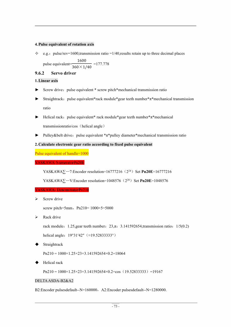
- 73 -
4.Pulse equivalent of rotation axis
e.g.:pulse/rev=1600,transmission ratio =1/40,results retain up to three decimal places
pulse equivalent=1600
360×1/40=177.778
9.6.2 Servo driver1.Linear axis
► Screw drive:pulse equivalent * screw pitch*mechanical transmission ratio
► Straightrack:pulse equivalent*rack module*gear teeth number*π*mechanical transmission
ratio
► Helical rack:pulse equivalent* rack module*gear teeth number*π*mechanical
transmissionratio/cos(helical angle)
► Pulley&belt drive:pulse equivalent *π*pulley diameter*mechanical transmission ratio
2.Calculate electronic gear ratio according to fixed pulse equivalent
Pulse equivalent of handle=1000
YASKAWA-NumeratorPn20E
YASKAWA∑—7:Encoder resolution=16777216(224)Set Pn20E=16777216
YASKAWA∑—V:Encoder resolution=1048576(220)Set Pn20E=1048576
YASKAWA- DenominatorPn210
Screw drive
screw pitch=5mm,Pn210= 1000×5=5000
Rack drive
rack module:1.25,gear teeth number:23,π:3.141592654,transmission ratio:1/5(0.2)
helical angle:19°31′42″(≈19.52833333°)
Straightrack
Pn210 = 1000×1.25×23×3.141592654×0.2=18064
Helical rack
Pn210 = 1000×1.25×23×3.141592654×0.2÷cos(19.52833333)=19167
DELTAASDA-B2&A2
B2:Encoder pulsesdefault--N=160000,A2:Encoder pulsesdefault--N=1280000.

- 74 -
e.g.B2 seriesN=160000
Screw drive
screw pitch=5mm,Denominator M=1000×5 = 5000
Electronic gear ratio=NM=1600005000
=321
Set P1-44=32,P1-45=1
Rack drive
rack module:1.25,gear teeth number:23,π:3.141592654,transmission ratio:1/5(0.2)
helical angle:19°31′42″(≈19.52833333°)
Straightrack
DenominatorM=1000×1.25×23×3.141592654×0.2=18064
Electronic gear ratio =NM=16000018064
=100001129
Set P1-44=10000,P1-45=1129
Helicalrack
Denominator M=1000×1.25×23×3.141592654×0.2÷cos(19.52833333)=19167
Electronic gear ratio =NM=16000019167
Set P1-44=160000,P1-45=19167
3.Calculate pulse equivalent according to fixed electronic gear ratio
B2: Electronic gear ratiodefault--16/10,A2: Electronic gear ratiodefault--N=128/10
e.g. B2:Set P1-44=1,P1-45=1,Encoder pulses2500×4=10000
Screw drive
screw pitch=5mm,pulse equivalent =100005
= 2000
Rack drive
rack module:1.25,gear teeth number:23,π:3.141592654,transmission ratio:1/5(0.2)
helical angle:19°31′42″(≈19.52833333°)
Straightrack (results retain up to three decimal places)
pulse equivalent=10000
1.25×23×3.141592654×0.2= 553.582
Helicalrack(results retain up to three decimal places)
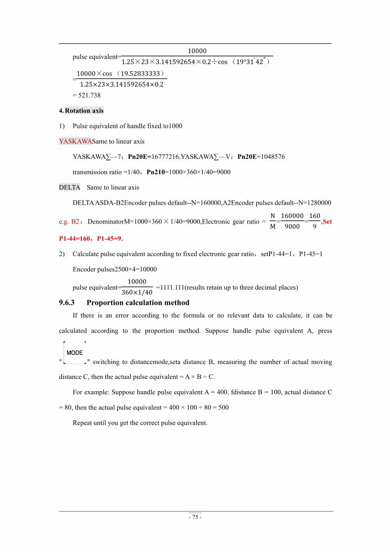
- 75 -
pulse equivalent=10000
1.25×23×3.141592654×0.2÷cos (19°31'42″)
=10000×cos (19.52833333)1.25×23×3.141592654×0.2
= 521.738
4.Rotation axis
1) Pulse equivalent of handle fixed to1000
YASKAWASame to linear axis
YASKAWA∑—7:Pn20E=16777216,YASKAWA∑—V:Pn20E=1048576
transmission ratio =1/40,Pn210=1000×360×1/40=9000
DELTA Same to linear axis
DELTAASDA-B2Encoder pulses default--N=160000,A2Encoder pulses default--N=1280000
e.g. B2:DenominatorM=1000×360×1/40=9000,Electronic gear ratio =NM=1600009000
=1609
,Set
P1-44=160,P1-45=9.
2) Calculate pulse equivalent according to fixed electronic gear ratio,setP1-44=1,P1-45=1
Encoder pulses2500×4=10000
pulse equivalent=10000
360×1/40=1111.111(results retain up to three decimal places)
9.6.3 Proportion calculation methodIf there is an error according to the formula or no relevant data to calculate, it can be
calculated according to the proportion method. Suppose handle pulse equivalent A, press
" " switching to distancemode,seta distance B, measuring the number of actual moving
distance C, then the actual pulse equivalent = A × B ÷ C.
For example: Suppose handle pulse equivalent A = 400, fdistance B = 100, actual distance C
= 80, then the actual pulse equivalent = 400 × 100 ÷ 80 = 500
Repeat until you get the correct pulse equivalent.

- 76 -
9.7 Common problems and troubleshooting9.7.1 Solutions of the faults display on the screen1.Screen flicker or automatically restart
1) Power supply is insufficient. Check power supply if there are problems, and change
high-quality power supply to solve the problems.
2) The local power grid unstable. Check local grid voltage stability,or increase the the regulator
filter device.
3) There are something wrong withthepower chip of the handle. This phenomenon also
appears when the handle is powered through the USB cable to the computer,please return
back the handle to our company.
4) Temporary solution, using standard 5V mobile phone charger, power supply through the USB
cable to handle. Dual power supply, can temporary emergency use.
2.Fail to set work origin
1) Get into the mechanical coordinate system. Press " " + " " to switch to work
coordinate system.
2) The buttons are broken. SYSTEM SETUP-Buttons Check,to check the buttons are normal or
not.
3.Assertion error
Assertion error occurred during the processing or after starting,Is generally a
software problem, you can boot assertion emergency recovery, or re-upgrade, if you
need to or can not recover Depot Repair
4.Do not read U-disk or errors occurred
1) Processing by U-disk, screen shows“There is no item in this direction”.Format U-disk to
FAT32,allocation unit change to the default configuration size.
2) Recommend U-disks of 2G 、4G、 8G
3) There is something wrong with U-disk interface or U-disk is broken,change new U-disk or
interface.
4) If the connection to U-disk interface is intermittent,users can copy files into inner.
5) Program containing the non-standard G code, or some illegal characters, the system read here,
- 77 -
does not recognize, interrupt handling. Recommend using professional simulation software to
view the program whether there is an illegal character. Delete all illegal characters.
9.7.2 Faults in practical operation1.The file size does not match the size of the actual set
1) Pulse equivalent is wrong.
2) You does not select the right tool.
3) Check the processing file.
2.The screen displays“beyondlimit”druing processing
1) The machine is not carried back to zero,the system is not able to confirm the actual
position. Make the machine back to zero.
2) After setting the working origin, the reserved range is less than the actual file size.Confirmthe
actual file size and set correct working origin.
3) You set the wrong working origin in the file. Check the path of the file, and re-export the
correct file.
3.Hard limitfalse triggering
1) System has connected with hard limit signal:maybe hard limit switch is broken or voltage
setupX6(X7-A18) is wrong.
2) System has not connected with hard limit signal:confirm that whether connect other signal to
hard limit X6(X7-A18),if not,check voltage setup normal or not,ifnormal,MACHINE
SETUP-Input Confi-disable X6(X7-A18), then wipe cache and system upgrade.
4.Z axis(spindle)fall down abnormally(too fast)and cause Z feed amount too much during
processing
1) Z axis working speed exceed the fastest speed cause Z axis looses its steps when moving up.
" MACHINESETUP " - " Max SpdLimit ",set the safe speed.
2) The coupling is loosing or transmission mechanism slipping. Re-adjustment the connecting
parts.
3) The signal wire connected between the interface board and the motor driver has got
interference. Adjust the circuit.
4) Processing file error. Check processing file, try to download the correct processing file to U
disk or handle internal.

- 78 -
5) There is something wrong(plug loosen or wire damaged or wire diameter is too slimsy)with
the lines connectting Z axis motor and motor driver. Replace the lines.
5.Repeating the same processing file after returing back to the machine ZERO, Z axis
cutting depths are not as same as each other
1) Machining table is uneven or processing object not firmly fixed, re-milling the machine table
to adjust the flatness.
2) Z-axis origin detection switch repeat positioning accuracy error, causing Z axis homing error
each time. Replace a high-quality detection switch.
3) Too much interference in the Z-axis homing process to form a false Z origin. Re-adjust the
wiring.
6.The machine can not stop after returning ZERO, and cause spindle hit the machine body
Double press“ ”to check input signal(Origin detection switch signal). To do self test.
Detect whether the signal is triggered or disconnected.
1) The origin detection switch is broken. Replace a new one.
2) The distance of the origin detection switch detection sheet beyond the detection range(This
problem is common occurs in optoelectronic and proximity switches) of the switch, adjust the
position of the test piece.
3) The origin detection switch to the interface board wiring aging or loosening. Check the
connections again.
4) The interface board is broken. Return back o us to repair.
5) 50-pin data cable is broken. Replace it with a new data cable.
7.The machine uniform moves to the reverse direction when backing to the machine ZERO
1) The origin detection switch types do not match with the definition of the corresponding
voltage level. Modify the voltage level in the controller. (Normally open type corresponds to
a level defined the direction of the arrow down, normally closed type corresponds to the level
defined arrow up).
2) The origin detection switch is broken. Replace a new one.
3) The origin detection switch connects interface board not well. Refresh the cable to confirm
the wiring is correct.

- 79 -
4) Too much interference, resulting in the illusion of the detection switch has been
triggered. Recalibrated the whole circuit.
5) The interface board is broken. Depot Repair.
6) 50-pin data cable is broken. Replace the data cable.
8.Abnormally running when processing or the actual file is different from theoretical file
1) The system program disorder.
2) Too much external interference cause the controller can not work normally.Re-adjust overall
circuit. (The wires of weak current and strong current should be separatedly binding, the
inverter and other components should be separated connected each GND of themselfves).
3) There is something wrong while converting the file format and the program appears illegal
characters or system unrecognized codes. Recommended to use third party simulation
software to review the program paths.
9.Start automatic tool setting, the tool does not stop after touching C.A.D(Tool sensor).
1) The cutter signal cable connects X4 maybe broken circuit.
2) The "GND" signal port on the interface board hasn’t been connected with spindle housing or
poor connection.
3) Go to “MACHINE SETUP”-“Input Confi” to confirm if X4 is enabled.
10. Coordinate value changes on screen, but the machine does not move
1) If it is one axis not moving, it maybe wiring problem.Change another normal terminal to this
axis wiring terminal, if it moves properly indicating the rear parts of motor dirver have no
problem. Check if there is something wrong with interface board or 50-pin cable. If it is still
not moving, it is necessary to detect the corresponding drive and motor.
2) If all axes are not moving, firstly, check if there are problems in the 50-pin cable and
interface board,; secondly, if the interface board and 50-pin cable are normal, then user
should check the power supply of the motor drivers.
3) If debugged all above parts, but the machine still not move, then the mechanical parts should
be checked.
11. It is normal to the move from one position to another position, but when return from
that position to the original position is not normal

- 80 -
Mechanical assembly problem, guide screw may be not installed well.
12. Motor moving direction is wrong
1) ExchangeA+&A- or B+&B- cable of the stepper motor
2) Change motor direction mask (not recommend)
13. The machine vibrates when moves in arc or two-axis linkage movement
1) Check whether the machine is placed horizontally
2) Check if the coupling units loose or not.
3) Increasing the “start speed”, avoid the resonance point.
PS7.3 Electrical components and wiring problem1.A single axis or multi axis can only in one direction after machine power on
1) There is something wrong with the conneccting between the the interface board and motor
driver common anode end, check the connection.
2) Interface board is broken. Replace the interface board.
3) The motor driver is broken. Replace the driver.
4) Measure the direction voltage of that axis with a multimete. Check if the direction is correct.
2.One axis motor does not move after handle power up
1) Pulse cable and direction cable connect oppositely,adjust connection sequence..
2) 5V common anode end of the motor driver disconnected, check the connection.
3) The motor driver is broken (Performance as the motor moves when push it by hand), change
a new one.
4) The interface chip of the interface board is broken, no pulse signal output.
5) Change this terminal to another normal termina to check interface board abnormal or driver
abnormal.
3.Screen is not bright after powerup, but connect the handle to computer with USB cable the
screen displays normally
1) The DC24V voltage of the handle is not available. Check if the DC24V power supply voltage
output is normal or not. If normal, please check if the cable from the power supply to the
interface board is virtual connection.
2) The 50-pin cable is broken or 50 pin connecting plug hasn’t connected well.

- 81 -
4.Screen is not bright neither after power up nor connect to computer by USB cable
1) This phenomenon may due to the handle shocked by external force or fall on the ground,
causing the crystal processor broken. Return back to repair.
2) Users connect high voltage power supply to the interface board and cause the handle and
interface board broken. Return back to repair.
5.The screen display“Spindle on”,actually the spindle off; the screen display“Spindle off”,
actually the spindle on
1) Line fault. Spindle on signal and Common port is short circuit. Check circuit line.
2) The output level definition reversed. Go to the “voltage setup” and modify the output level
definition (modify the left first arrow direction in the second row).
6.The handle screen doesn’t light up and shows nothing after power on
1) The power supply voltage is too large or the + and – short circuit burned the chip. Return to us
for repairing.
2) The power supply damaged, change a new one.
3) 50-pin cable is broken, replace it.
4) 50-pin socket broken, send back to us for repairing.
7.System always alarm after the alarm signal has been connected
Change the input level on X5 (normally open,wiring in parallel; normally closed,wiring in
series).
8.Press “spindle on” button, but spindle does not start
1) Check wiring, if normal, check if the interver has alarm, if the inverter is normal and its
setting is correct, and then check if the spindle motor damaged or not.
2) Check if 50-pin cable is loose. Confirm the settings of invertor refer to its manual to debug
one by one.
3) Check interface board. Press“ ” to start spindle, use multimeter to measure Y1 and
GND to see whether conducting, if not, maybe interface board or 50-pin cable is broken. To
replace a nomal one for trouble clearing one by one.