SERVICE MANUAL (Machine code: C244/C239) - stencil.wiki
89
SERVICE MANUAL (Machine code: C244/C239)
-
Upload
khangminh22 -
Category
Documents
-
view
1 -
download
0
Transcript of SERVICE MANUAL (Machine code: C244/C239) - stencil.wiki
SERVICE MANUAL(Machine code: C244/C239)

i
TABLE OF CONTENTS
1. OVERALL INFORMATION ......................................................... 1-11.1 ESSENTIAL DIFFERENCES BETWEEN C244/C239 AND
C235 MODELS..........................................................................................1-11.2 SPECIFICATIONS...............................................................................1-11.2.1 FOR MODEL #C244.........................................................................1-11.2.2 FOR MODEL #C239.........................................................................1-2
1.3 NEW ELECTRICAL COMPONENTS ........................................................1-31.3.1 FOR MODEL #C244.........................................................................1-3
Printed Circuit Board Layout (For model #C244) ..................................1-3Paper Feed Section (For model #C244) ...............................................1-3Master Making Unit (For model #C244) ................................................1-4Table of Electrical Components ............................................................1-4
1.3.2 FOR MODEL #C239.........................................................................1-5Printed Circuit Board Layout (For model #C239) ..................................1-5Master Making Unit (For model #C239) ................................................1-5Table of Electrical Components ............................................................1-6Others ...................................................................................................1-6
2. DETAILED DESCRIPTIONS ....................................................... 2-12.1 IMAGE PROCESSING ..............................................................................2-1
2.1.1 THERMAL HEAD..............................................................................2-1Specifications........................................................................................2-1
2.2 MASTER FEED.........................................................................................2-12.2.1 OVERVIEW ......................................................................................2-12.2.2 MODIFICATIONS FOR JAM REMOVAL..........................................2-2
Master Duct Sensor Mechanism...........................................................2-2Pull-out distance ...................................................................................2-3Master Shutter Mechanism...................................................................2-4
2.3 PAPER FEED............................................................................................2-52.3.1 DOUBLE FEED DETECTION MECHANISM....................................2-52.3.2 MASTER MAKING AND FEED MECHANISM..................................2-6
Master Feed Mechanism ......................................................................2-62.4 DRUM........................................................................................................2-7
Drum Idling Mechanism ........................................................................2-7
3. INSTALLATION .......................................................................... 3-13.1 EDITING FUNCTION TYPE 85 INSTALLATION (OPTION)......................3-1
3.1.1 ACCESSORY CHECK LIST .............................................................3-13.1.2 INSTALLATION PROCEDURE ........................................................3-1
3.2 INTERFACE CABLE TYPE 85 INSTALLATION (OPTION)......................3-23.2.1 INSTALLATION PROCEDURE ........................................................3-2
ii
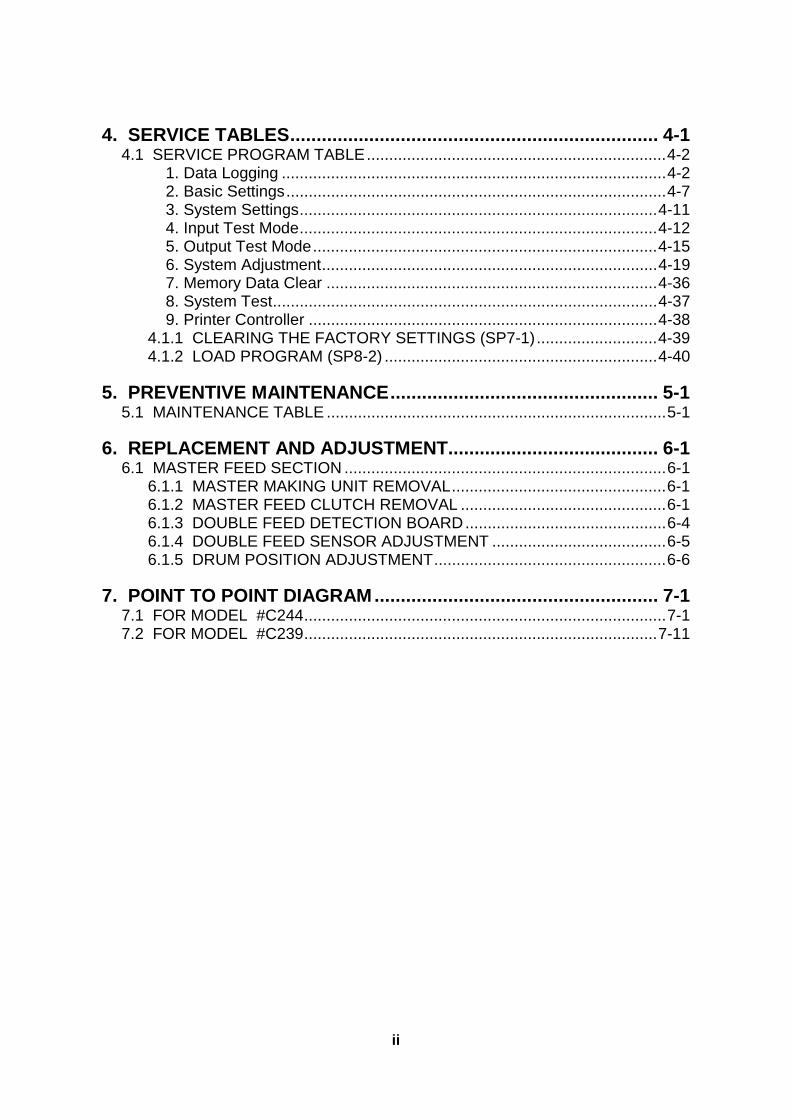
4. SERVICE TABLES...................................................................... 4-14.1 SERVICE PROGRAM TABLE...................................................................4-2
1. Data Logging ......................................................................................4-22. Basic Settings.....................................................................................4-73. System Settings................................................................................4-114. Input Test Mode................................................................................4-125. Output Test Mode.............................................................................4-156. System Adjustment...........................................................................4-197. Memory Data Clear ..........................................................................4-368. System Test......................................................................................4-379. Printer Controller ..............................................................................4-38
4.1.1 CLEARING THE FACTORY SETTINGS (SP7-1)...........................4-394.1.2 LOAD PROGRAM (SP8-2) .............................................................4-40
5. PREVENTIVE MAINTENANCE................................................... 5-15.1 MAINTENANCE TABLE ............................................................................5-1
6. REPLACEMENT AND ADJUSTMENT........................................ 6-16.1 MASTER FEED SECTION ........................................................................6-1
6.1.1 MASTER MAKING UNIT REMOVAL................................................6-16.1.2 MASTER FEED CLUTCH REMOVAL ..............................................6-16.1.3 DOUBLE FEED DETECTION BOARD.............................................6-46.1.4 DOUBLE FEED SENSOR ADJUSTMENT .......................................6-56.1.5 DRUM POSITION ADJUSTMENT....................................................6-6
7. POINT TO POINT DIAGRAM...................................................... 7-17.1 FOR MODEL #C244.................................................................................7-17.2 FOR MODEL #C239...............................................................................7-11
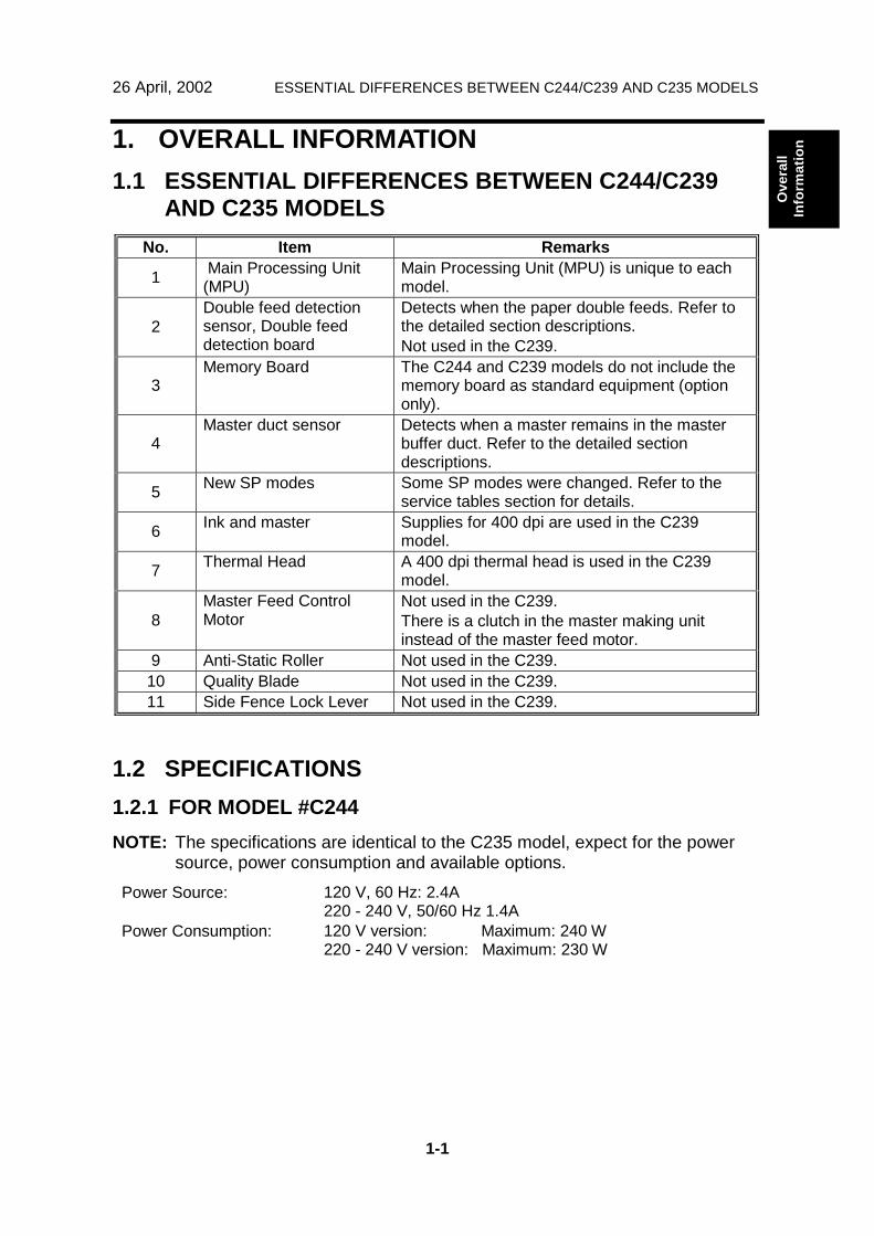
26 April, 2002 ESSENTIAL DIFFERENCES BETWEEN C244/C239 AND C235 MODELS
1-1
Ove
rall
Info
rmat
ion1. OVERALL INFORMATION
1.1 ESSENTIAL DIFFERENCES BETWEEN C244/C239AND C235 MODELS
No. Item Remarks
1 Main Processing Unit(MPU)
Main Processing Unit (MPU) is unique to eachmodel.
2Double feed detectionsensor, Double feeddetection board
Detects when the paper double feeds. Refer tothe detailed section descriptions.Not used in the C239.
3Memory Board The C244 and C239 models do not include the
memory board as standard equipment (optiononly).
4Master duct sensor Detects when a master remains in the master
buffer duct. Refer to the detailed sectiondescriptions.
5 New SP modes Some SP modes were changed. Refer to theservice tables section for details.
6 Ink and master Supplies for 400 dpi are used in the C239model.
7 Thermal Head A 400 dpi thermal head is used in the C239model.
8Master Feed ControlMotor
Not used in the C239.There is a clutch in the master making unitinstead of the master feed motor.
9 Anti-Static Roller Not used in the C239.10 Quality Blade Not used in the C239.11 Side Fence Lock Lever Not used in the C239.
1.2 SPECIFICATIONS1.2.1 FOR MODEL #C244NOTE: The specifications are identical to the C235 model, expect for the power
source, power consumption and available options.Power Source: 120 V, 60 Hz: 2.4A
220 - 240 V, 50/60 Hz 1.4APower Consumption: 120 V version: Maximum: 240 W
220 - 240 V version: Maximum: 230 W
SPECIFICATIONS 26 April, 2002
1-2
Available Options: A3 DrumA4 DrumDocument FeederExposure Glass CoverInterface Cable Type85Editing Function Type85Printer Unit Type 80RCP80SorterTC-II
1.2.2 FOR MODEL #C239
NOTE: 1) Only the items that are differences from the C235 model are shownbelow.
2) Master and ink are different from the C235 model. Supplies for C233model are not commonly used in the C239 model.
Master Processing: Digital with 400 dpi thermal headScanning (Pixel Density): 400 dpi CCDMaster Process Time: Platen mode:
Less than 16 seconds (A3 paper)Less than 12 seconds (A4 paper)
ADF mode:Less than 20 seconds (A3 paper)Less than 17 seconds (A4 paper)
Master Eject BoxCapacity:
60 masters / A3 size (Normal conditions)
Power Source: 120 V, 60 Hz: 3.2A220 - 240 V, 50/60 Hz 1.7 A
Power Consumption: 120 V version: Maximum: 340 W220 - 240 V version: Maximum: 320 W
Weight: 97 kg [213.9 lb]104 kg [229.3 lb] with ADF
Master Type: Thermal master roll type:320 mm width, 110 m/roll
Yield:200 masters/roll (at A3 size)
Max run length per master:2,000 prints
Available Options: A3 DrumA4 DrumDocument FeederExposure Glass CoverInterface Cable Type85Editing Function Type85Printer Unit Type 80RCP80SorterTC-II
Ricoh Technical Services
RTB 16 This item is incorrect (Garnet only)
26 April, 2002 NEW ELECTRICAL COMPONENTS
1-3
Ove
rall
Info
rmat
ion1.3 NEW ELECTRICAL COMPONENTS
1.3.1 FOR MODEL #C244
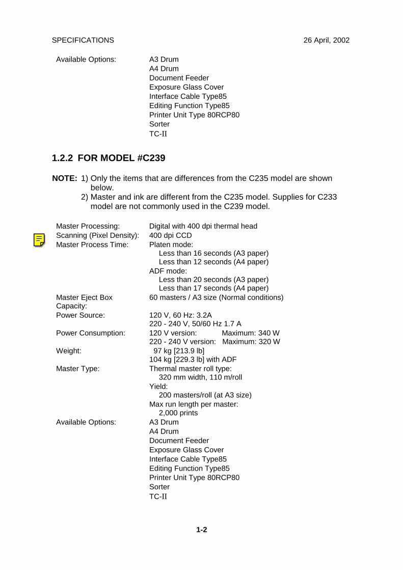
Printed Circuit Board Layout (For model #C244)
Paper Feed Section (For model #C244)
C244V103.WMF
C244V001.WMF
2
3
1
NEW ELECTRICAL COMPONENTS 26 April, 2002
1-4
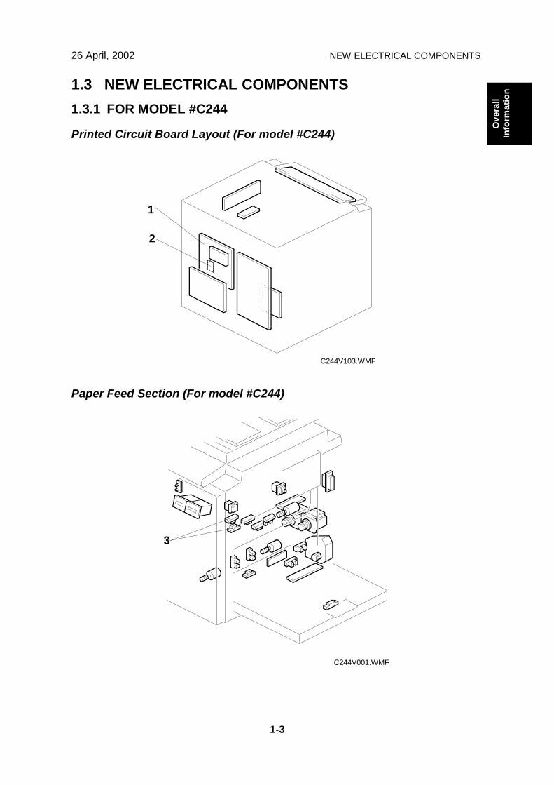
Master Making Unit (For model #C244)
Table of Electrical Components
BoardsIndex No. Name Function
1 Main Processing Unit (MPU) Controls all machine functions both directlyand through other boards.
2 Double Feed Detector Board Controls the double feed sensor
SensorsIndex No. Name Function
3 Double Feed Sensor Detects the paper double feeds
4 Master Duct Sensor Detects when a master remains in themaster buffer duct
C244V000.WMF
4
26 April, 2002 NEW ELECTRICAL COMPONENTS
1-5
Ove
rall
Info
rmat
ion
1.3.2 FOR MODEL #C239
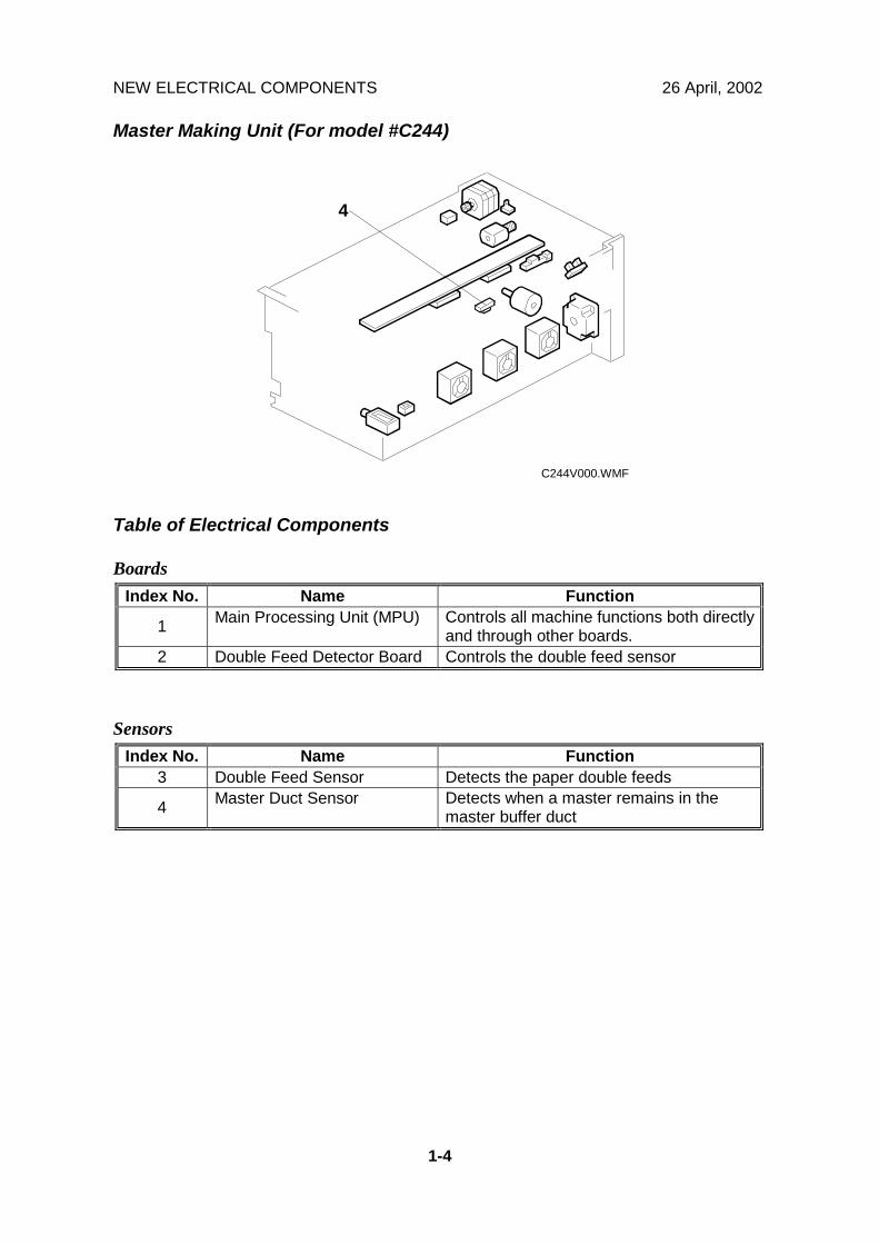
Printed Circuit Board Layout (For model #C239)
Master Making Unit (For model #C239)
C239V501.WMF
C239V001.WMF
6
5
7
NEW ELECTRICAL COMPONENTS 26 April, 2002
1-6
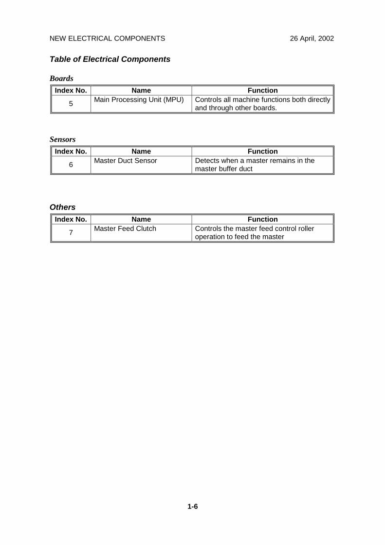
Table of Electrical Components
BoardsIndex No. Name Function
5 Main Processing Unit (MPU) Controls all machine functions both directlyand through other boards.
SensorsIndex No. Name Function
6 Master Duct Sensor Detects when a master remains in themaster buffer duct
OthersIndex No. Name Function
7 Master Feed Clutch Controls the master feed control rolleroperation to feed the master
26 April, 2002 IMAGE PROCESSING
2-1
Det
aile
dD
escr
iptio
ns
2. DETAILED DESCRIPTIONSIn this section, only the detailed descriptions that are unique to the C239 and C244models are explained.
2.1 IMAGE PROCESSING2.1.1 THERMAL HEADFor model #C239Specifications
• Length .................................................. 292.6 mm• Number of thermal head elements ....... 4608• Density of thermal head elements........ 400 dpi
NOTE: The thermal head of the C244 is common with the C235 model.
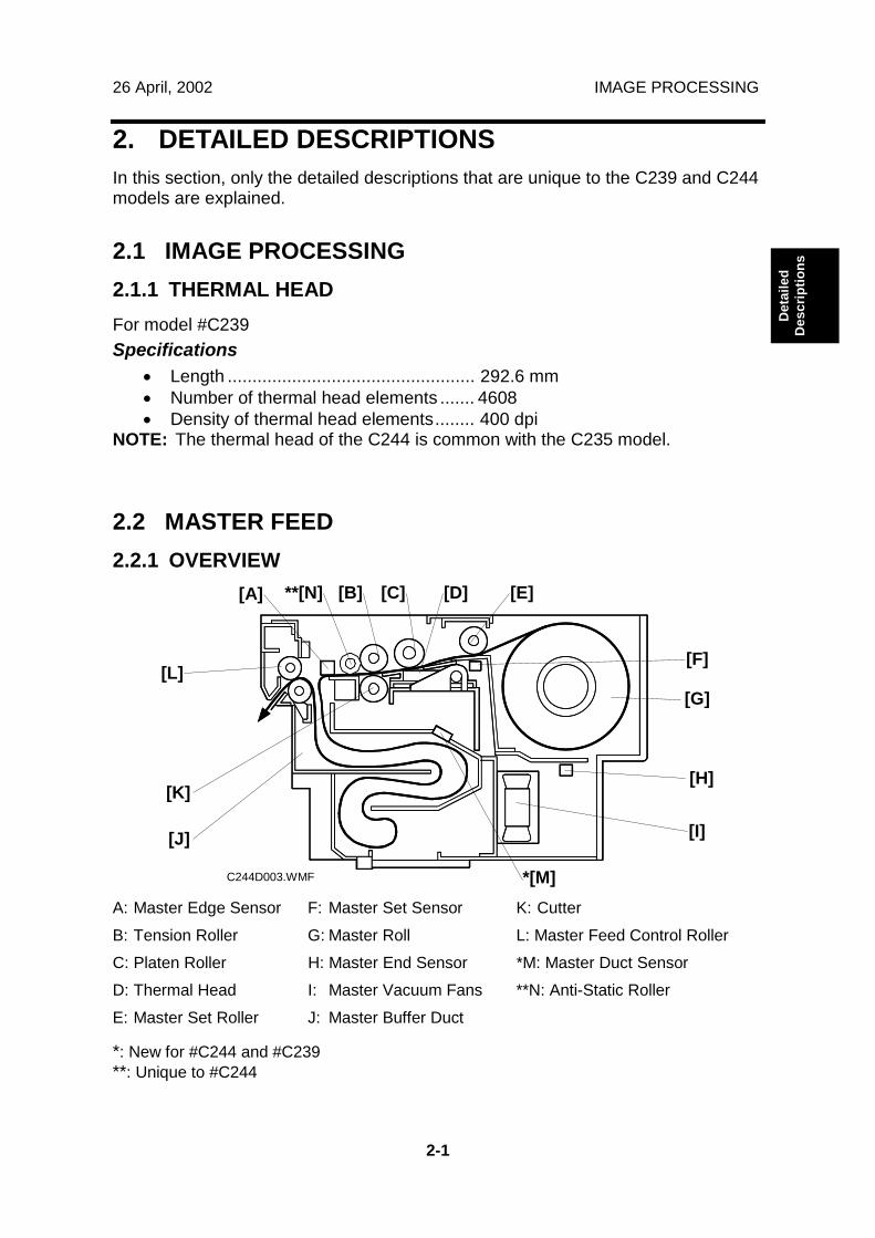
2.2 MASTER FEED2.2.1 OVERVIEW
A: Master Edge Sensor F: Master Set Sensor K: CutterB: Tension Roller G: Master Roll L: Master Feed Control RollerC: Platen Roller H: Master End Sensor *M: Master Duct SensorD: Thermal Head I: Master Vacuum Fans **N: Anti-Static RollerE: Master Set Roller J: Master Buffer Duct
*: New for #C244 and #C239**: Unique to #C244
C244D003.WMF
[A] [B] [C] [D] [E]
[F]
[G]
[H]
[I][J]
[K]
[L]
*[M]
**[N]
MASTER FEED 26 April, 2002
2-2
2.2.2 MODIFICATIONS FOR JAM REMOVAL
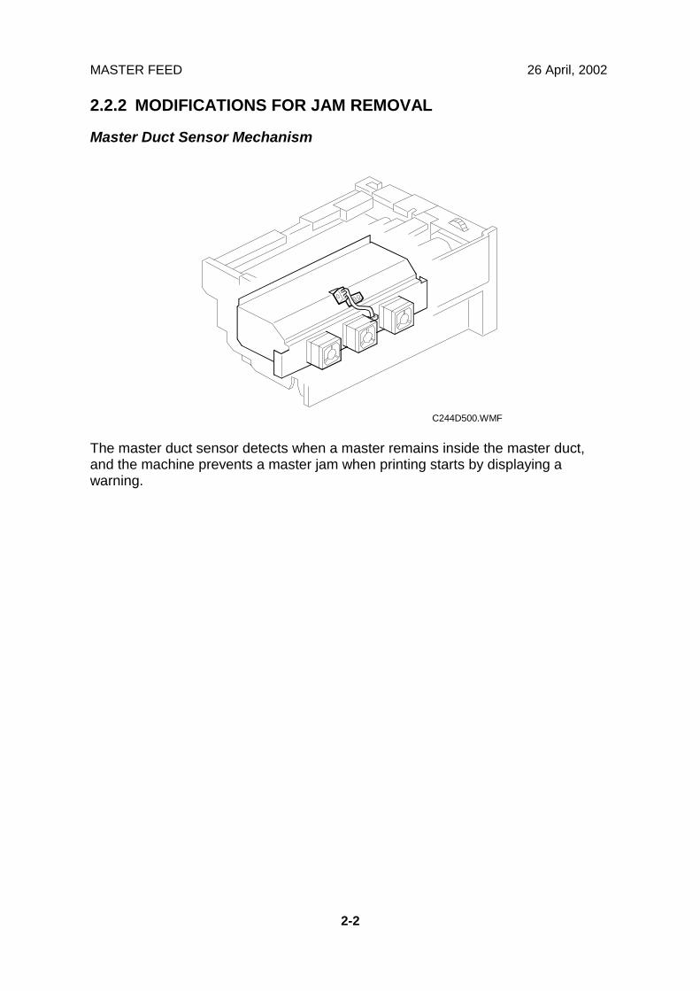
Master Duct Sensor Mechanism
The master duct sensor detects when a master remains inside the master duct,and the machine prevents a master jam when printing starts by displaying awarning.
C244D500.WMF
26 April, 2002 MASTER FEED
2-3
Det
aile
dD
escr
iptio
ns
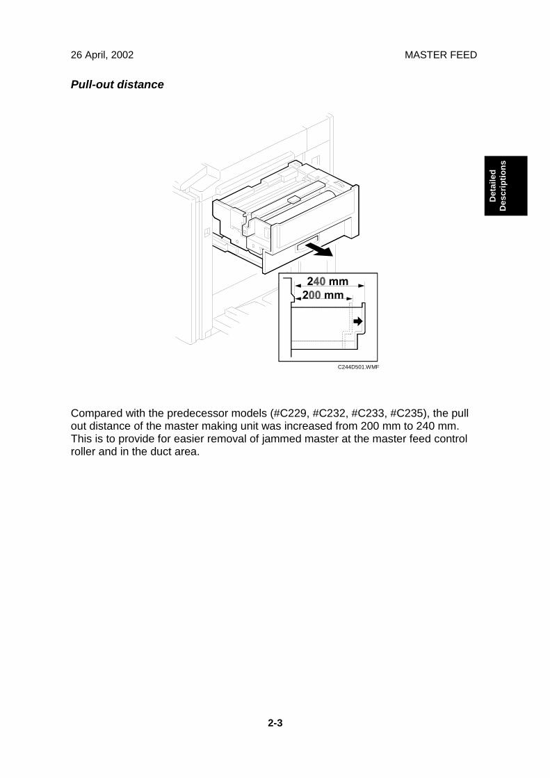
Pull-out distance
Compared with the predecessor models (#C229, #C232, #C233, #C235), the pullout distance of the master making unit was increased from 200 mm to 240 mm.This is to provide for easier removal of jammed master at the master feed controlroller and in the duct area.
C244D501.WMF
MASTER FEED 26 April, 2002
2-4
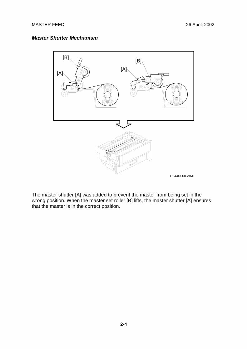
Master Shutter Mechanism
The master shutter [A] was added to prevent the master from being set in thewrong position. When the master set roller [B] lifts, the master shutter [A] ensuresthat the master is in the correct position.
C244D000.WMF
[A][A]
[B][B]
26 April, 2002 PAPER FEED
2-5
Det
aile
dD
escr
iptio
ns
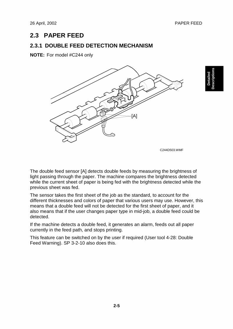
2.3 PAPER FEED2.3.1 DOUBLE FEED DETECTION MECHANISMNOTE: For model #C244 only
The double feed sensor [A] detects double feeds by measuring the brightness oflight passing through the paper. The machine compares the brightness detectedwhile the current sheet of paper is being fed with the brightness detected while theprevious sheet was fed.The sensor takes the first sheet of the job as the standard, to account for thedifferent thicknesses and colors of paper that various users may use. However, thismeans that a double feed will not be detected for the first sheet of paper, and italso means that if the user changes paper type in mid-job, a double feed could bedetected.If the machine detects a double feed, it generates an alarm, feeds out all papercurrently in the feed path, and stops printing.This feature can be switched on by the user if required (User tool 4-28: DoubleFeed Warning). SP 3-2-10 also does this.
C244D503.WMF
[A]
PAPER FEED 26 April, 2002
2-6
2.3.2 MASTER MAKING AND FEED MECHANISM
NOTE: 1) For model#C239 only.2) This mechanism in the C239 is the same as in the C233.
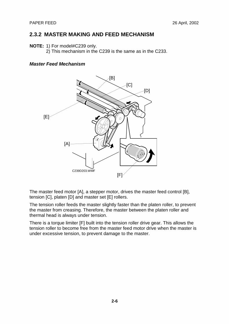
Master Feed Mechanism
The master feed motor [A], a stepper motor, drives the master feed control [B],tension [C], platen [D] and master set [E] rollers.The tension roller feeds the master slightly faster than the platen roller, to preventthe master from creasing. Therefore, the master between the platen roller andthermal head is always under tension.There is a torque limiter [F] built into the tension roller drive gear. This allows thetension roller to become free from the master feed motor drive when the master isunder excessive tension, to prevent damage to the master.
C239D203.WMF
[A]
[B][C]
[D]
[E]
[F]
26 April, 2002 DRUM
2-7
Det
aile
dD
escr
iptio
ns
2.4 DRUM
NOTE: 1) For model #C239 only (the drum for C244 is the same as for C235)2) This mechanism in the C239 is the same as in the C229 and C233.
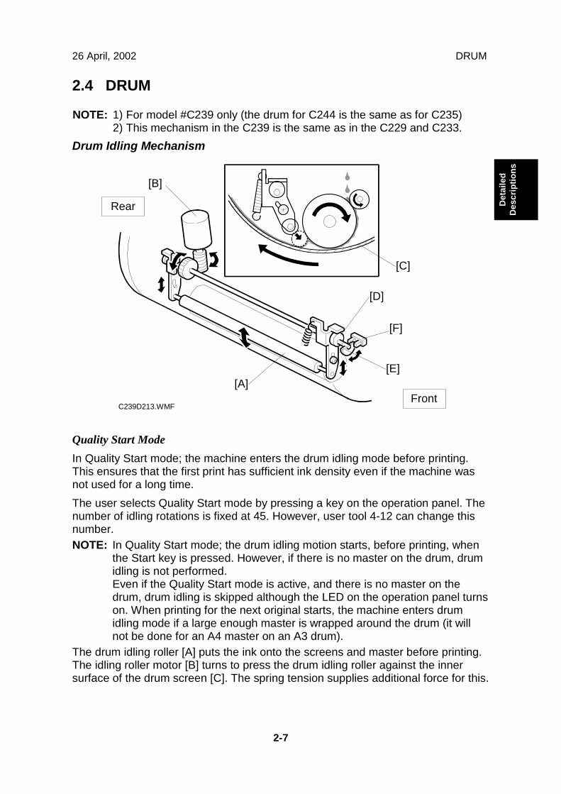
Drum Idling Mechanism
Quality Start ModeIn Quality Start mode; the machine enters the drum idling mode before printing.This ensures that the first print has sufficient ink density even if the machine wasnot used for a long time.The user selects Quality Start mode by pressing a key on the operation panel. Thenumber of idling rotations is fixed at 45. However, user tool 4-12 can change thisnumber.NOTE: In Quality Start mode; the drum idling motion starts, before printing, when
the Start key is pressed. However, if there is no master on the drum, drumidling is not performed.Even if the Quality Start mode is active, and there is no master on thedrum, drum idling is skipped although the LED on the operation panel turnson. When printing for the next original starts, the machine enters drumidling mode if a large enough master is wrapped around the drum (it willnot be done for an A4 master on an A3 drum).
The drum idling roller [A] puts the ink onto the screens and master before printing.The idling roller motor [B] turns to press the drum idling roller against the innersurface of the drum screen [C]. The spring tension supplies additional force for this.
C239D213.WMF
[B]
[C]
[D]
[F]
[E][A]
Front
Rear
DRUM 26 April, 2002
2-8
The cam [D] is turned by the motor, moving the drum idling roller towards the drumscreen. The actuator disk [E] interrupts the idling roller HP sensor [F] when thedrum idling roller is being used.
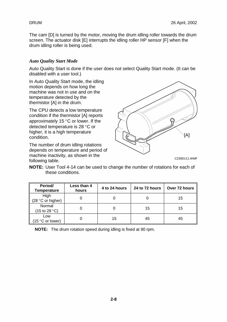
Auto Quality Start ModeAuto Quality Start is done if the user does not select Quality Start mode. (It can bedisabled with a user tool.)In Auto Quality Start mode, the idlingmotion depends on how long themachine was not in use and on thetemperature detected by thethermistor [A] in the drum.The CPU detects a low temperaturecondition if the thermistor [A] reportsapproximately 15 °C or lower. If thedetected temperature is 28 °C orhigher, it is a high temperaturecondition.The number of drum idling rotationsdepends on temperature and period ofmachine inactivity, as shown in thefollowing table.NOTE: User Tool 4-14 can be used to change the number of rotations for each of
these conditions.
Period/Temperature
Less than 4hours 4 to 24 hours 24 to 72 hours Over 72 hours
High(28 °C or higher) 0 0 0 15
Normal(15 to 28 °C) 0 0 15 15
Low(15 °C or lower) 0 15 45 45
NOTE: The drum rotation speed during idling is fixed at 90 rpm.
C239D111.WMF
[A]
26 April, 2002 DRUM
2-9
Det
aile
dD
escr
iptio
ns
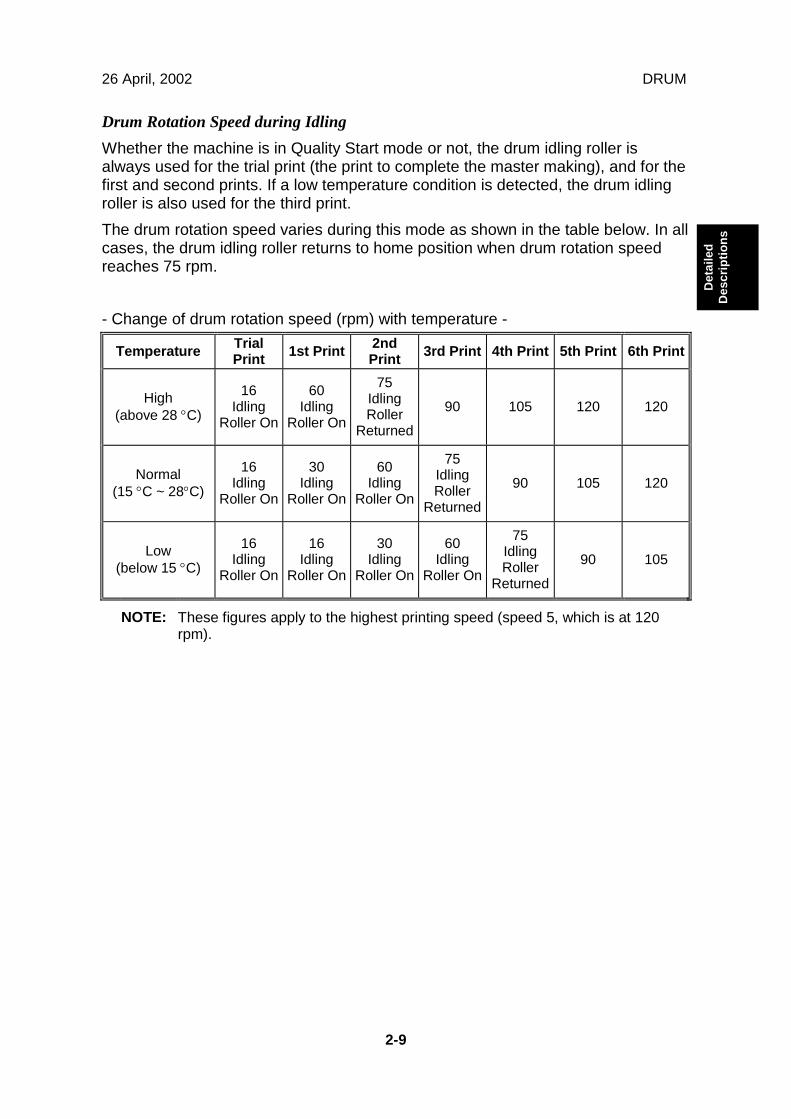
Drum Rotation Speed during IdlingWhether the machine is in Quality Start mode or not, the drum idling roller isalways used for the trial print (the print to complete the master making), and for thefirst and second prints. If a low temperature condition is detected, the drum idlingroller is also used for the third print.The drum rotation speed varies during this mode as shown in the table below. In allcases, the drum idling roller returns to home position when drum rotation speedreaches 75 rpm.
- Change of drum rotation speed (rpm) with temperature -
Temperature TrialPrint 1st Print 2nd
Print 3rd Print 4th Print 5th Print 6th Print
High(above 28 °C)
16Idling
Roller On
60Idling
Roller On
75IdlingRoller
Returned
90 105 120 120
Normal(15 °C ~ 28°C)
16Idling
Roller On
30Idling
Roller On
60Idling
Roller On
75IdlingRoller
Returned
90 105 120
Low(below 15 °C)
16Idling
Roller On
16Idling
Roller On
30Idling
Roller On
60Idling
Roller On
75IdlingRoller
Returned
90 105
NOTE: These figures apply to the highest printing speed (speed 5, which is at 120rpm).
26 April, 2002 EDITING FUNCTION TYPE 85 INSTALLATION (OPTION)
3-1
Inst
alla
tion
3. INSTALLATIONThere are no differences from the C235 model in this section, except that theEditing Function Type 85, the Interface Cable Type 85 installation procedures wereadded.
3.1 EDITING FUNCTION TYPE 85 INSTALLATION(OPTION)
3.1.1 ACCESSORY CHECK LIST
Check the quantity and condition of the accessories in the box against the followinglist:
Description Quantity
1. Stepped Screw............................................................................... 2
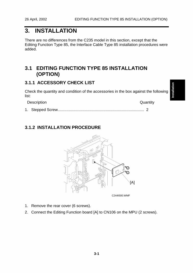
3.1.2 INSTALLATION PROCEDURE
1. Remove the rear cover (6 screws).2. Connect the Editing Function board [A] to CN106 on the MPU (2 screws).
C244I500.WMF
[A]
INTERFACE CABLE TYPE 85 INSTALLATION (OPTION) 26 April, 2002
3-2
3.2 INTERFACE CABLE TYPE 85 INSTALLATION(OPTION)
Check the quantity and condition of the accessories in the box against the followinglist:
Description Quantity
1. Screw............................................................................................. 22. Spacer ........................................................................................... 23. Video I/F board .............................................................................. 14. Cable ............................................................................................. 15. Bind................................................................................................ 1
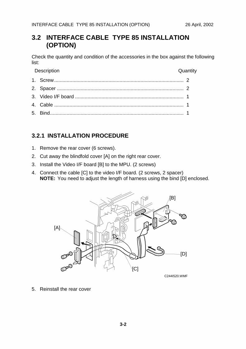
3.2.1 INSTALLATION PROCEDURE
1. Remove the rear cover (6 screws).2. Cut away the blindfold cover [A] on the right rear cover.3. Install the Video I/F board [B] to the MPU. (2 screws)4. Connect the cable [C] to the video I/F board. (2 screws, 2 spacer)
NOTE: You need to adjust the length of harness using the bind [D] enclosed.
5. Reinstall the rear cover
C244I520.WMF
[A]
[B]
[C]
[D]

26 April, 2002 SERVICE PROGRAM TABLE
4-1
Serv
ice
Tabl
es
4. SERVICE TABLESSome SP modes were checked or newly added for the C244 and C239 models.The following table shows all of the items in the service program mode.
NOTE: The marks beside the SP mode numbers in the following tables representthe following meanings.*: A new item was added or the default setting was changed.**: New item, used for the C239 models but not used for the C244 models.***: New item, used for the C244 models but not used for the C239 models.
Main Menu Number List
1. Data Logging2. Basic Settings3. System Settings4. Input Test Mode5. Output Test Mode6. System Adjustment7. Memory Data Clear8. System Test9. Printer Controller
SERVICE PROGRAM TABLE 26 April, 2002
4-2
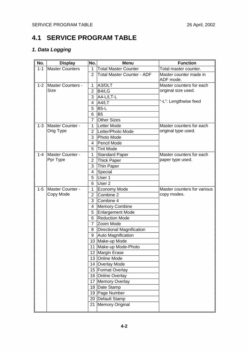
4.1 SERVICE PROGRAM TABLE1. Data Logging
No. Display No. Menu Function1 Total Master Counter Total master counter.1-1 Master Counters2 Total Master Counter - ADF Master counter made in
ADF mode.1 A3/DLT2 B4/LG3 A4-L/LT-L4 A4/LT5 B5-L6 B5
1-2 Master Counters -Size
7 Other Sizes
Master counters for eachoriginal size used.
“-L”: Lengthwise feed
1 Letter Mode2 Letter/Photo Mode3 Photo Mode4 Pencil Mode
1-3 Master Counter -Orig Type
5 Tint Mode
Master counters for eachoriginal type used.
1 Standard Paper2 Thick Paper3 Thin Paper4 Special5 User 1
1-4 Master Counter -Ppr Type
6 User 2
Master counters for eachpaper type used.
1 Economy Mode2 Combine 23 Combine 44 Memory Combine5 Enlargement Mode6 Reduction Mode7 Zoom Mode8 Directional Magnification9 Auto Magnification10 Make-up Mode11 Make-up Mode-Photo12 Margin Erase13 Online Mode14 Overlay Mode15 Format Overlay16 Online Overlay17 Memory Overlay18 Date Stamp19 Page Number20 Default Stamp
1-5 Master Counter -Copy Mode
21 Memory Original
Master counters for variouscopy modes.
26 April, 2002 SERVICE PROGRAM TABLE
4-3
Serv
ice
Tabl
es
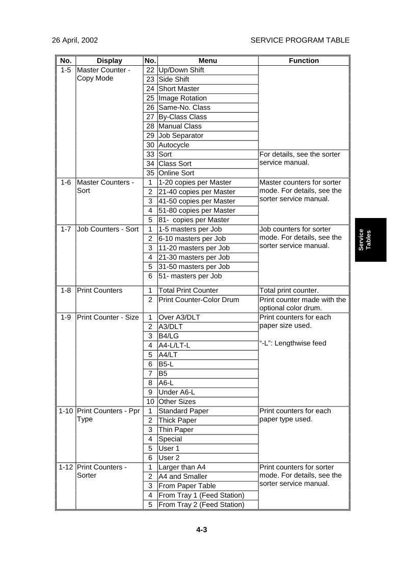
No. Display No. Menu Function22 Up/Down Shift23 Side Shift24 Short Master25 Image Rotation26 Same-No. Class27 By-Class Class28 Manual Class29 Job Separator30 Autocycle33 Sort34 Class Sort
1-5 Master Counter -Copy Mode
35 Online Sort
For details, see the sorterservice manual.
1 1-20 copies per Master2 21-40 copies per Master3 41-50 copies per Master4 51-80 copies per Master
1-6 Master Counters -Sort
5 81- copies per Master
Master counters for sortermode. For details, see thesorter service manual.
1 1-5 masters per Job2 6-10 masters per Job3 11-20 masters per Job4 21-30 masters per Job5 31-50 masters per Job
1-7 Job Counters - Sort
6 51- masters per Job
Job counters for sortermode. For details, see thesorter service manual.
1 Total Print Counter Total print counter.1-8 Print Counters2 Print Counter-Color Drum Print counter made with the
optional color drum.1 Over A3/DLT2 A3/DLT3 B4/LG4 A4-L/LT-L5 A4/LT6 B5-L7 B58 A6-L9 Under A6-L
1-9 Print Counter - Size
10 Other Sizes
Print counters for eachpaper size used.
“-L”: Lengthwise feed
1 Standard Paper2 Thick Paper3 Thin Paper4 Special5 User 1
1-10 Print Counters - PprType
6 User 2
Print counters for eachpaper type used.
1 Larger than A42 A4 and Smaller3 From Paper Table4 From Tray 1 (Feed Station)
1-12 Print Counters -Sorter
5 From Tray 2 (Feed Station)
Print counters for sortermode. For details, see thesorter service manual.
SERVICE PROGRAM TABLE 26 April, 2002
4-4
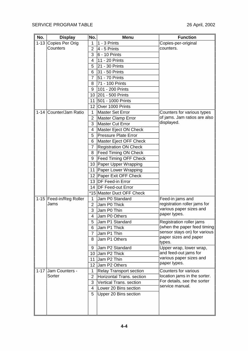
No. Display No. Menu Function1 1 - 3 Prints2 4 - 5 Prints3 6 - 10 Prints4 11 - 20 Prints5 21 - 30 Prints6 31 - 50 Prints7 51 - 70 Prints8 71 - 100 Prints9 101 - 200 Prints10 201 - 500 Prints11 501 - 1000 Prints
1-13 Copies Per OrigCounters
12 Over 1000 Prints
Copies-per-originalcounters.
1 Master Set Error2 Master Clamp Error3 Master Cut Error4 Master Eject ON Check5 Pressure Plate Error6 Master Eject OFF Check7 Registration ON Check8 Feed Timing ON Check9 Feed Timing OFF Check10 Paper Upper Wrapping11 Paper Lower Wrapping12 Paper Exit OFF Check13 DF Feed-in Error14 DF Feed-out Error
1-14 Counter/Jam Ratio
*15 Master Duct OFF Check
Counters for various typesof jams. Jam ratios are alsodisplayed.
1 Jam P0 Standard2 Jam P0 Thick3 Jam P0 Thin4 Jam P0 Others
Feed-in jams andregistration roller jams forvarious paper sizes andpaper types.
5 Jam P1 Standard6 Jam P1 Thick7 Jam P1 Thin8 Jam P1 Others
Registration roller jams(when the paper feed timingsensor stays on) for variouspaper sizes and papertypes.
9 Jam P2 Standard10 Jam P2 Thick11 Jam P2 Thin
1-15 Feed-in/Reg RollerJams
12 Jam P2 Others
Upper wrap, lower wrap,and feed-out jams forvarious paper sizes andpaper types.
1 Relay Transport section2 Horizontal Trans. section3 Vertical Trans. section4 Lower 20 Bins section
1-17 Jam Counters -Sorter
5 Upper 20 Bins section
Counters for variouslocation jams in the sorter.For details, see the sorterservice manual.
26 April, 2002 SERVICE PROGRAM TABLE
4-5
Serv
ice
Tabl
es
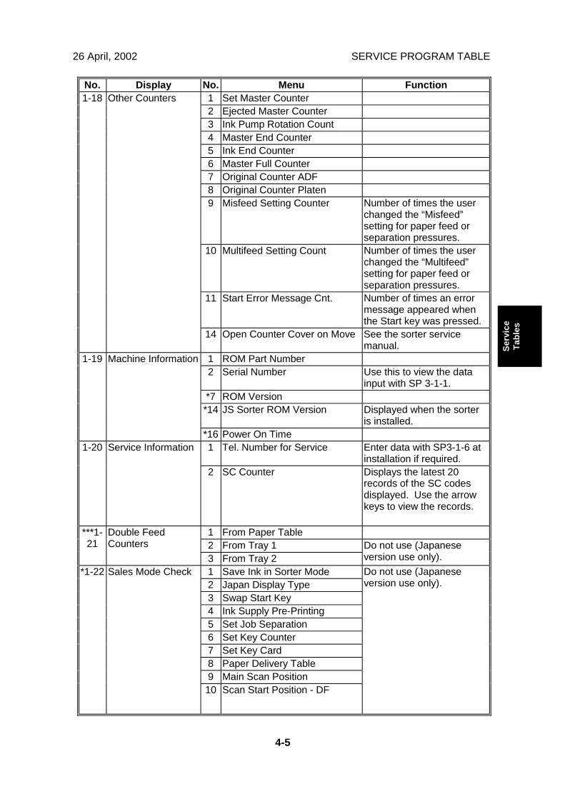
No. Display No. Menu Function1 Set Master Counter2 Ejected Master Counter3 Ink Pump Rotation Count4 Master End Counter5 Ink End Counter6 Master Full Counter7 Original Counter ADF8 Original Counter Platen9 Misfeed Setting Counter Number of times the user
changed the “Misfeed”setting for paper feed orseparation pressures.
10 Multifeed Setting Count Number of times the userchanged the “Multifeed”setting for paper feed orseparation pressures.
11 Start Error Message Cnt. Number of times an errormessage appeared whenthe Start key was pressed.
1-18 Other Counters
14 Open Counter Cover on Move See the sorter servicemanual.
1 ROM Part Number2 Serial Number Use this to view the data
input with SP 3-1-1.*7 ROM Version*14 JS Sorter ROM Version Displayed when the sorter
is installed.
1-19 Machine Information
*16 Power On Time1 Tel. Number for Service Enter data with SP3-1-6 at
installation if required.1-20 Service Information
2 SC Counter Displays the latest 20records of the SC codesdisplayed. Use the arrowkeys to view the records.
1 From Paper Table2 From Tray 1
***1-21
Double FeedCounters
3 From Tray 2Do not use (Japaneseversion use only).
1 Save Ink in Sorter Mode2 Japan Display Type3 Swap Start Key4 Ink Supply Pre-Printing5 Set Job Separation6 Set Key Counter7 Set Key Card8 Paper Delivery Table9 Main Scan Position
*1-22 Sales Mode Check
10 Scan Start Position - DF
Do not use (Japaneseversion use only).

SERVICE PROGRAM TABLE 26 April, 2002
4-6
No. Display No. Menu Function11 Scanning Speed*12 Config data*13 Controller NVRAM
*1-22 Sales Mode Check
*14 NIB NVRAM
Do not use (Japaneseversion use only).
26 April, 2002 SERVICE PROGRAM TABLE
4-7
Serv
ice
Tabl
es
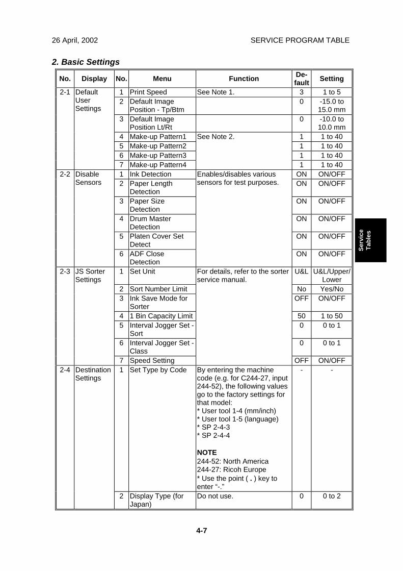
2. Basic Settings
No. Display No. Menu Function De-fault Setting
1 Print Speed See Note 1. 3 1 to 52 Default Image
Position - Tp/Btm0 -15.0 to
15.0 mm3 Default Image
Position Lt/Rt0 -10.0 to
10.0 mm4 Make-up Pattern1 1 1 to 405 Make-up Pattern2 1 1 to 406 Make-up Pattern3 1 1 to 40
2-1 DefaultUserSettings
7 Make-up Pattern4
See Note 2.
1 1 to 401 Ink Detection ON ON/OFF2 Paper Length
DetectionON ON/OFF
3 Paper SizeDetection
ON ON/OFF
4 Drum MasterDetection
ON ON/OFF
5 Platen Cover SetDetect
ON ON/OFF
2-2 DisableSensors
6 ADF CloseDetection
Enables/disables varioussensors for test purposes.
ON ON/OFF
1 Set Unit U&L U&L/Upper/Lower
2 Sort Number Limit No Yes/No3 Ink Save Mode for
SorterOFF ON/OFF
4 1 Bin Capacity Limit 50 1 to 505 Interval Jogger Set -
Sort0 0 to 1
6 Interval Jogger Set -Class
0 0 to 1
2-3 JS SorterSettings
7 Speed Setting
For details, refer to the sorterservice manual.
OFF ON/OFF1 Set Type by Code By entering the machine
code (e.g. for C244-27, input244-52), the following valuesgo to the factory settings forthat model:* User tool 1-4 (mm/inch)* User tool 1-5 (language)* SP 2-4-3* SP 2-4-4
NOTE244-52: North America244-27: Ricoh Europe* Use the point ( . ) key toenter “-.”
- -2-4 DestinationSettings
2 Display Type (forJapan)
Do not use. 0 0 to 2
SERVICE PROGRAM TABLE 26 April, 2002
4-8
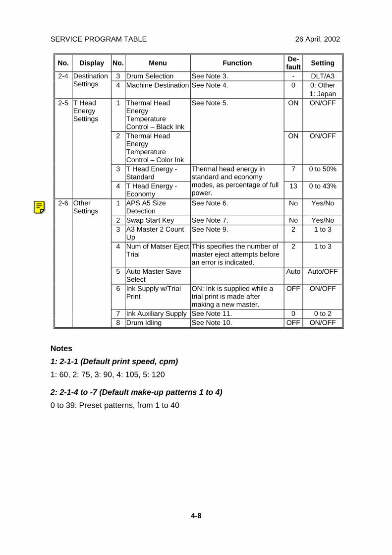
No. Display No. Menu Function De-fault Setting
3 Drum Selection See Note 3. - DLT/A32-4 DestinationSettings 4 Machine Destination See Note 4. 0 0: Other
1: Japan1 Thermal Head
EnergyTemperatureControl – Black Ink
ON ON/OFF
2 Thermal HeadEnergyTemperatureControl – Color Ink
See Note 5.
ON ON/OFF
3 T Head Energy -Standard
7 0 to 50%
2-5 T HeadEnergySettings
4 T Head Energy -Economy
Thermal head energy instandard and economymodes, as percentage of fullpower.
13 0 to 43%
1 APS A5 SizeDetection
See Note 6. No Yes/No
2 Swap Start Key See Note 7. No Yes/No3 A3 Master 2 Count
UpSee Note 9. 2 1 to 3
4 Num of Matser EjectTrial
This specifies the number ofmaster eject attempts beforean error is indicated.
2 1 to 3
5 Auto Master SaveSelect
Auto Auto/OFF
6 Ink Supply w/TrialPrint
ON: Ink is supplied while atrial print is made aftermaking a new master.
OFF ON/OFF
7 Ink Auxiliary Supply See Note 11. 0 0 to 2
2-6 OtherSettings
8 Drum Idling See Note 10. OFF ON/OFF
Notes1: 2-1-1 (Default print speed, cpm)1: 60, 2: 75, 3: 90, 4: 105, 5: 120
2: 2-1-4 to -7 (Default make-up patterns 1 to 4)0 to 39: Preset patterns, from 1 to 40
Ricoh Technical Services
2-6-20 RTB 12b: New SP
26 April, 2002 SERVICE PROGRAM TABLE
4-9
Serv
ice
Tabl
es
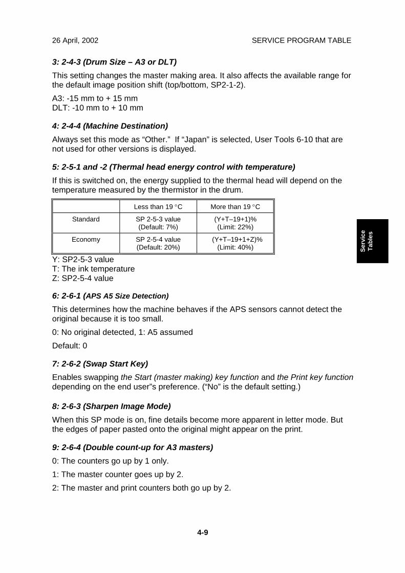
3: 2-4-3 (Drum Size – A3 or DLT)This setting changes the master making area. It also affects the available range forthe default image position shift (top/bottom, SP2-1-2).A3: -15 mm to + 15 mmDLT: -10 mm to + 10 mm
4: 2-4-4 (Machine Destination)Always set this mode as “Other.” If “Japan” is selected, User Tools 6-10 that arenot used for other versions is displayed.
5: 2-5-1 and -2 (Thermal head energy control with temperature)If this is switched on, the energy supplied to the thermal head will depend on thetemperature measured by the thermistor in the drum.
Less than 19 °C More than 19 °C
Standard SP 2-5-3 value(Default: 7%)
(Y+T–19+1)% (Limit: 22%)
Economy SP 2-5-4 value(Default: 20%)
(Y+T–19+1+Z)% (Limit: 40%)
Y: SP2-5-3 valueT: The ink temperatureZ: SP2-5-4 value
6: 2-6-1 (APS A5 Size Detection)
This determines how the machine behaves if the APS sensors cannot detect theoriginal because it is too small.0: No original detected, 1: A5 assumedDefault: 0
7: 2-6-2 (Swap Start Key)Enables swapping the Start (master making) key function and the Print key functiondepending on the end user”s preference. (“No” is the default setting.)
8: 2-6-3 (Sharpen Image Mode)When this SP mode is on, fine details become more apparent in letter mode. Butthe edges of paper pasted onto the original might appear on the print.
9: 2-6-4 (Double count-up for A3 masters)0: The counters go up by 1 only.1: The master counter goes up by 2.2: The master and print counters both go up by 2.
SERVICE PROGRAM TABLE 26 April, 2002
4-10
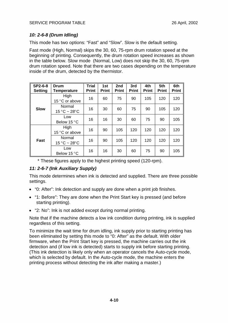
10: 2-6-8 (Drum Idling)This mode has two options: “Fast” and “Slow”. Slow is the default setting.Fast mode (High, Normal) skips the 30, 60, 75-rpm drum rotation speed at thebeginning of printing. Consequently, the drum rotation speed increases as shownin the table below. Slow mode (Normal, Low) does not skip the 30, 60, 75-rpmdrum rotation speed. Note that there are two cases depending on the temperatureinside of the drum, detected by the thermistor.
SP2-6-8Setting
DrumTemperature
TrialPrint
1stPrint
2ndPrint
3rdPrint
4thPrint
5thPrint
6thPrint
High15 °C or above 16 60 75 90 105 120 120
Normal15 °C ~ 28°C 16 30 60 75 90 105 120Slow
LowBelow 15 °C 16 16 30 60 75 90 105
High15 °C or above 16 90 105 120 120 120 120
Normal15 °C ~ 28°C 16 90 105 120 120 120 120Fast
LowBelow 15 °C 16 16 30 60 75 90 105
* These figures apply to the highest printing speed (120-rpm).11: 2-6-7 (Ink Auxiliary Supply)This mode determines when ink is detected and supplied. There are three possiblesettings.
• “0: After”: Ink detection and supply are done when a print job finishes.
• “1: Before”: They are done when the Print Start key is pressed (and beforestarting printing).
• “2: No”: Ink is not added except during normal printing.Note that if the machine detects a low ink condition during printing, ink is suppliedregardless of this setting.To minimize the wait time for drum idling, ink supply prior to starting printing hasbeen eliminated by setting this mode to “0: After” as the default. With olderfirmware, when the Print Start key is pressed, the machine carries out the inkdetection and (if low ink is detected) starts to supply ink before starting printing.(This ink detection is likely only when an operator cancels the Auto-cycle mode,which is selected by default. In the Auto-cycle mode, the machine enters theprinting process without detecting the ink after making a master.)
26 April, 2002 SERVICE PROGRAM TABLE
4-11
Serv
ice
Tabl
es
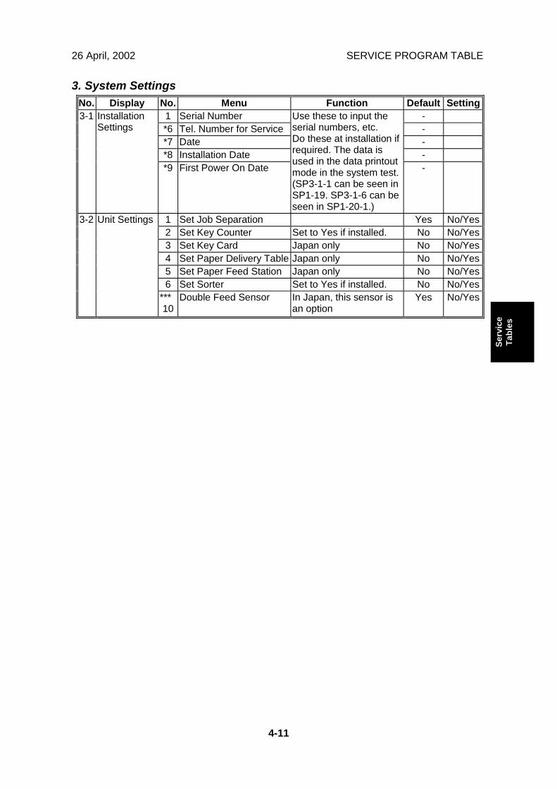
3. System SettingsNo. Display No. Menu Function Default Setting
1 Serial Number -*6 Tel. Number for Service -*7 Date -*8 Installation Date -
3-1 InstallationSettings
*9 First Power On Date
Use these to input theserial numbers, etc.Do these at installation ifrequired. The data isused in the data printoutmode in the system test.(SP3-1-1 can be seen inSP1-19. SP3-1-6 can beseen in SP1-20-1.)
-
1 Set Job Separation Yes No/Yes2 Set Key Counter Set to Yes if installed. No No/Yes3 Set Key Card Japan only No No/Yes4 Set Paper Delivery Table Japan only No No/Yes5 Set Paper Feed Station Japan only No No/Yes6 Set Sorter Set to Yes if installed. No No/Yes
3-2 Unit Settings
***10
Double Feed Sensor In Japan, this sensor isan option
Yes No/Yes
SERVICE PROGRAM TABLE 26 April, 2002
4-12
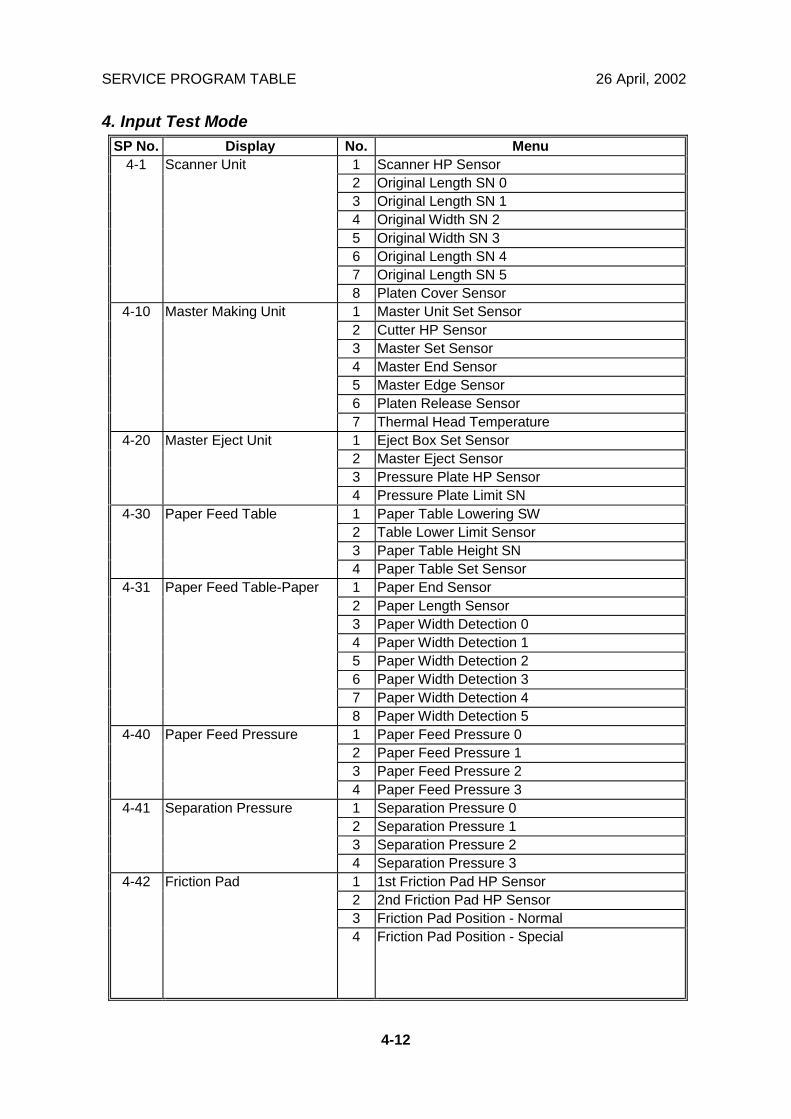
4. Input Test ModeSP No. Display No. Menu
1 Scanner HP Sensor2 Original Length SN 03 Original Length SN 14 Original Width SN 25 Original Width SN 36 Original Length SN 47 Original Length SN 5
4-1 Scanner Unit
8 Platen Cover Sensor1 Master Unit Set Sensor2 Cutter HP Sensor3 Master Set Sensor4 Master End Sensor5 Master Edge Sensor6 Platen Release Sensor
4-10 Master Making Unit
7 Thermal Head Temperature1 Eject Box Set Sensor2 Master Eject Sensor3 Pressure Plate HP Sensor
4-20 Master Eject Unit
4 Pressure Plate Limit SN1 Paper Table Lowering SW2 Table Lower Limit Sensor3 Paper Table Height SN
4-30 Paper Feed Table
4 Paper Table Set Sensor1 Paper End Sensor2 Paper Length Sensor3 Paper Width Detection 04 Paper Width Detection 15 Paper Width Detection 26 Paper Width Detection 37 Paper Width Detection 4
4-31 Paper Feed Table-Paper
8 Paper Width Detection 51 Paper Feed Pressure 02 Paper Feed Pressure 13 Paper Feed Pressure 2
4-40 Paper Feed Pressure
4 Paper Feed Pressure 31 Separation Pressure 02 Separation Pressure 13 Separation Pressure 2
4-41 Separation Pressure
4 Separation Pressure 31 1st Friction Pad HP Sensor2 2nd Friction Pad HP Sensor3 Friction Pad Position - Normal
4-42 Friction Pad
4 Friction Pad Position - Special
26 April, 2002 SERVICE PROGRAM TABLE
4-13
Serv
ice
Tabl
es
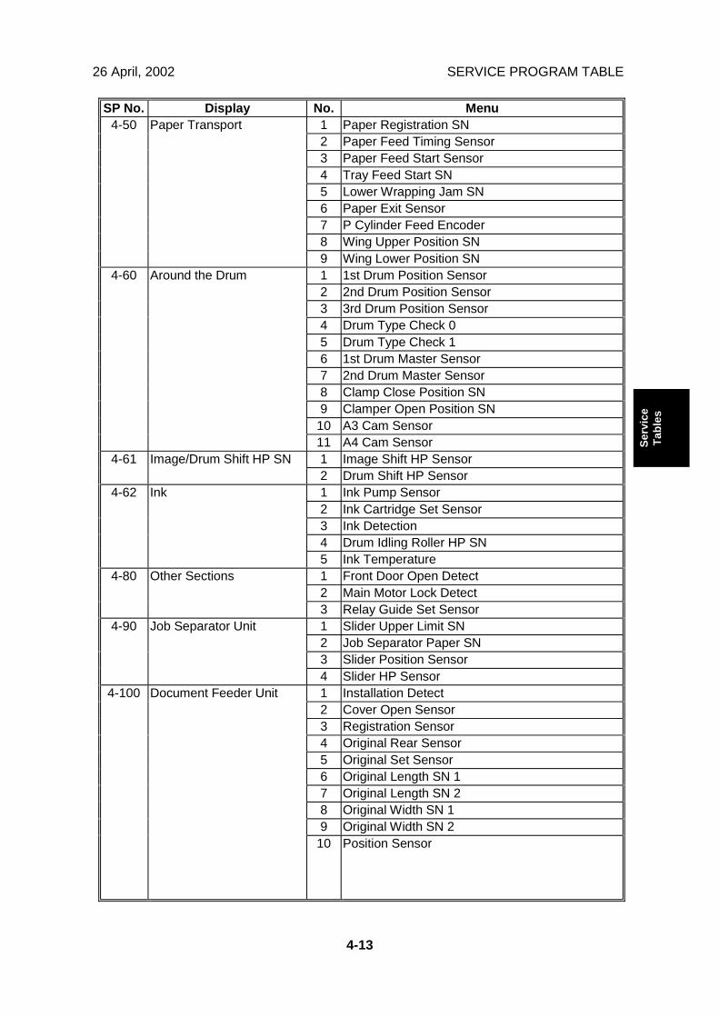
SP No. Display No. Menu1 Paper Registration SN2 Paper Feed Timing Sensor3 Paper Feed Start Sensor4 Tray Feed Start SN5 Lower Wrapping Jam SN6 Paper Exit Sensor7 P Cylinder Feed Encoder8 Wing Upper Position SN
4-50 Paper Transport
9 Wing Lower Position SN1 1st Drum Position Sensor2 2nd Drum Position Sensor3 3rd Drum Position Sensor4 Drum Type Check 05 Drum Type Check 16 1st Drum Master Sensor7 2nd Drum Master Sensor8 Clamp Close Position SN9 Clamper Open Position SN
10 A3 Cam Sensor
4-60 Around the Drum
11 A4 Cam Sensor1 Image Shift HP Sensor4-61 Image/Drum Shift HP SN2 Drum Shift HP Sensor1 Ink Pump Sensor2 Ink Cartridge Set Sensor3 Ink Detection4 Drum Idling Roller HP SN
4-62 Ink
5 Ink Temperature1 Front Door Open Detect2 Main Motor Lock Detect
4-80 Other Sections
3 Relay Guide Set Sensor1 Slider Upper Limit SN2 Job Separator Paper SN3 Slider Position Sensor
4-90 Job Separator Unit
4 Slider HP Sensor1 Installation Detect2 Cover Open Sensor3 Registration Sensor4 Original Rear Sensor5 Original Set Sensor6 Original Length SN 17 Original Length SN 28 Original Width SN 19 Original Width SN 2
4-100 Document Feeder Unit
10 Position Sensor
SERVICE PROGRAM TABLE 26 April, 2002
4-14
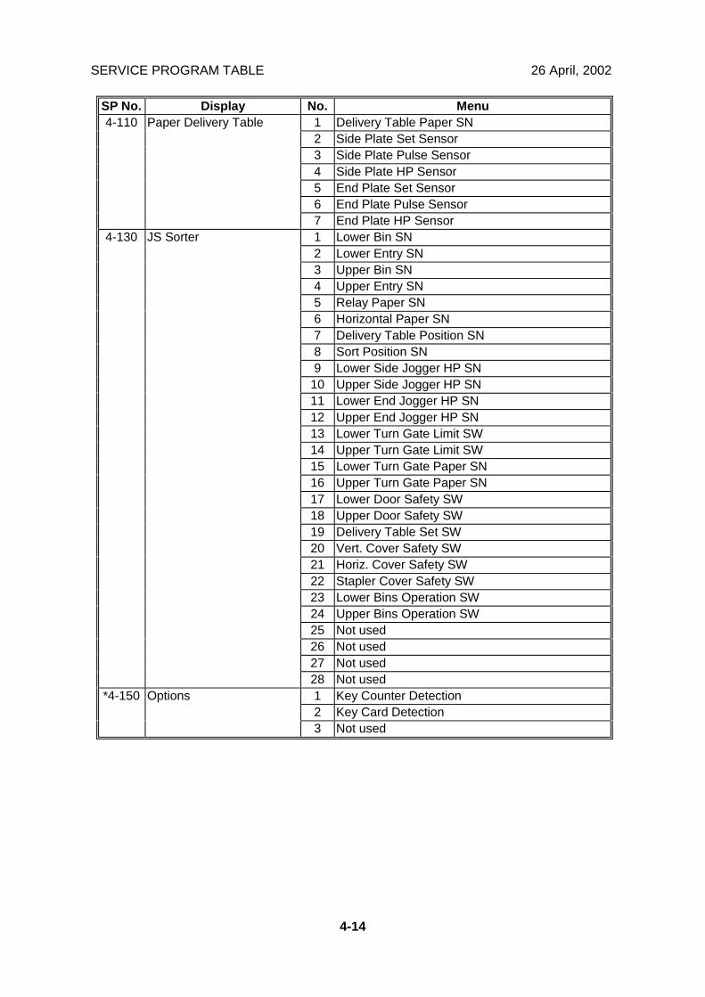
SP No. Display No. Menu1 Delivery Table Paper SN2 Side Plate Set Sensor3 Side Plate Pulse Sensor4 Side Plate HP Sensor5 End Plate Set Sensor6 End Plate Pulse Sensor
4-110 Paper Delivery Table
7 End Plate HP Sensor1 Lower Bin SN2 Lower Entry SN3 Upper Bin SN4 Upper Entry SN5 Relay Paper SN6 Horizontal Paper SN7 Delivery Table Position SN8 Sort Position SN9 Lower Side Jogger HP SN
10 Upper Side Jogger HP SN11 Lower End Jogger HP SN12 Upper End Jogger HP SN13 Lower Turn Gate Limit SW14 Upper Turn Gate Limit SW15 Lower Turn Gate Paper SN16 Upper Turn Gate Paper SN17 Lower Door Safety SW18 Upper Door Safety SW19 Delivery Table Set SW20 Vert. Cover Safety SW21 Horiz. Cover Safety SW22 Stapler Cover Safety SW23 Lower Bins Operation SW24 Upper Bins Operation SW25 Not used26 Not used27 Not used
4-130 JS Sorter
28 Not used1 Key Counter Detection2 Key Card Detection
*4-150 Options
3 Not used
26 April, 2002 SERVICE PROGRAM TABLE
4-15
Serv
ice
Tabl
es
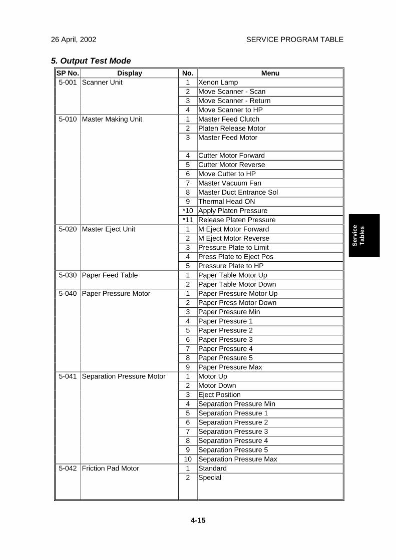
5. Output Test ModeSP No. Display No. Menu
1 Xenon Lamp2 Move Scanner - Scan3 Move Scanner - Return
5-001 Scanner Unit
4 Move Scanner to HP1 Master Feed Clutch2 Platen Release Motor3 Master Feed Motor
4 Cutter Motor Forward5 Cutter Motor Reverse6 Move Cutter to HP7 Master Vacuum Fan8 Master Duct Entrance Sol9 Thermal Head ON
*10 Apply Platen Pressure
5-010 Master Making Unit
*11 Release Platen Pressure1 M Eject Motor Forward2 M Eject Motor Reverse3 Pressure Plate to Limit4 Press Plate to Eject Pos
5-020 Master Eject Unit
5 Pressure Plate to HP1 Paper Table Motor Up5-030 Paper Feed Table2 Paper Table Motor Down1 Paper Pressure Motor Up2 Paper Press Motor Down3 Paper Pressure Min4 Paper Pressure 15 Paper Pressure 26 Paper Pressure 37 Paper Pressure 48 Paper Pressure 5
5-040 Paper Pressure Motor
9 Paper Pressure Max1 Motor Up2 Motor Down3 Eject Position4 Separation Pressure Min5 Separation Pressure 16 Separation Pressure 27 Separation Pressure 38 Separation Pressure 49 Separation Pressure 5
5-041 Separation Pressure Motor
10 Separation Pressure Max1 Standard5-042 Friction Pad Motor2 Special
SERVICE PROGRAM TABLE 26 April, 2002
4-16
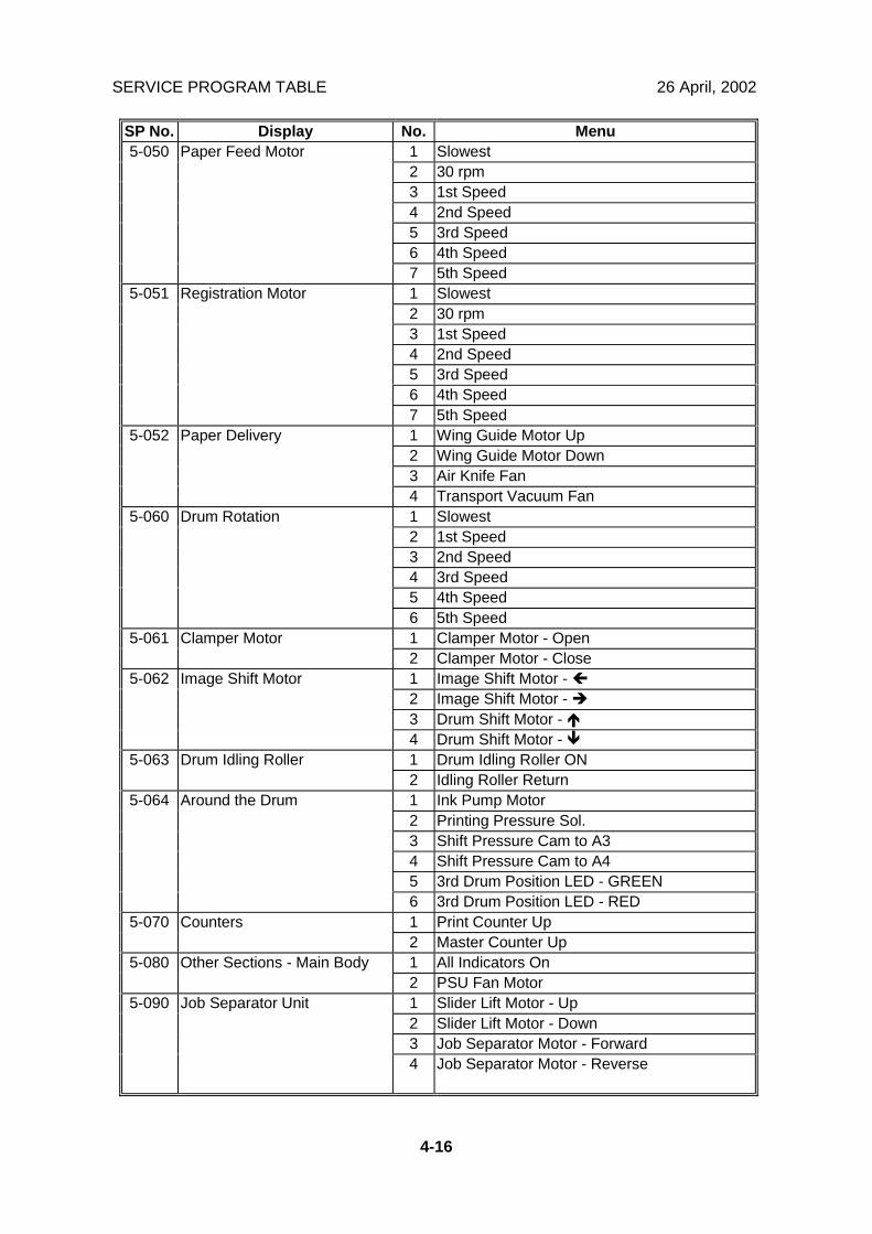
SP No. Display No. Menu1 Slowest2 30 rpm3 1st Speed4 2nd Speed5 3rd Speed6 4th Speed
5-050 Paper Feed Motor
7 5th Speed1 Slowest2 30 rpm3 1st Speed4 2nd Speed5 3rd Speed6 4th Speed
5-051 Registration Motor
7 5th Speed1 Wing Guide Motor Up2 Wing Guide Motor Down3 Air Knife Fan
5-052 Paper Delivery
4 Transport Vacuum Fan1 Slowest2 1st Speed3 2nd Speed4 3rd Speed5 4th Speed
5-060 Drum Rotation
6 5th Speed1 Clamper Motor - Open5-061 Clamper Motor2 Clamper Motor - Close1 Image Shift Motor - !2 Image Shift Motor - "3 Drum Shift Motor - #
5-062 Image Shift Motor
4 Drum Shift Motor - $1 Drum Idling Roller ON5-063 Drum Idling Roller2 Idling Roller Return1 Ink Pump Motor2 Printing Pressure Sol.3 Shift Pressure Cam to A34 Shift Pressure Cam to A45 3rd Drum Position LED - GREEN
5-064 Around the Drum
6 3rd Drum Position LED - RED1 Print Counter Up5-070 Counters2 Master Counter Up1 All Indicators On5-080 Other Sections - Main Body2 PSU Fan Motor1 Slider Lift Motor - Up2 Slider Lift Motor - Down3 Job Separator Motor - Forward
5-090 Job Separator Unit
4 Job Separator Motor - Reverse
26 April, 2002 SERVICE PROGRAM TABLE
4-17
Serv
ice
Tabl
es
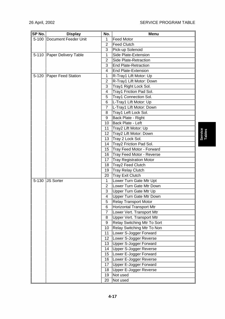
SP No. Display No. Menu1 Feed Motor2 Feed Clutch
5-100 Document Feeder Unit
3 Pick-up Solenoid1 Side Plate-Extension2 Side Plate-Retraction3 End Plate-Retraction
5-110 Paper Delivery Table
4 End Plate-Extension1 R-Tray1 Lift Motor: Up2 R-Tray1 Lift Motor: Down3 Tray1 Right Lock Sol.4 Tray1 Friction Pad Sol.5 Tray1 Connection Sol.6 L-Tray1 Lift Motor: Up7 L-Tray1 Lift Motor: Down8 Tray1 Left Lock Sol.9 Back Plate - Right
10 Back Plate - Left11 Tray2 Lift Motor: Up12 Tray2 Lift Motor: Down13 Tray 2 Lock Sol.14 Tray2 Friction Pad Sol.15 Tray Feed Motor - Forward16 Tray Feed Motor - Reverse17 Tray Registration Motor18 Tray2 Feed Clutch19 Tray Relay Clutch
5-120 Paper Feed Station
20 Tray Exit Clutch1 Lower Turn Gate Mtr Upt2 Lower Turn Gate Mtr Down3 Upper Turn Gate Mtr Up4 Upper Turn Gate Mtr Down5 Relay Transport Motor6 Horizontal Transport Mtr7 Lower Vert. Transport Mtr8 Upper Vert. Transport Mtr9 Relay Switching Mtr To Sort
10 Relay Switching Mtr To Non11 Lower S-Jogger Forward12 Lower S-Jogger Reverse13 Upper S-Jogger Forward14 Upper S-Jogger Reverse15 Lower E-Jogger Forward16 Lower E-Jogger Reverse17 Upper E-Jogger Forward18 Upper E-Jogger Reverse19 Not used
5-130 JS Sorter
20 Not used
SERVICE PROGRAM TABLE 26 April, 2002
4-18
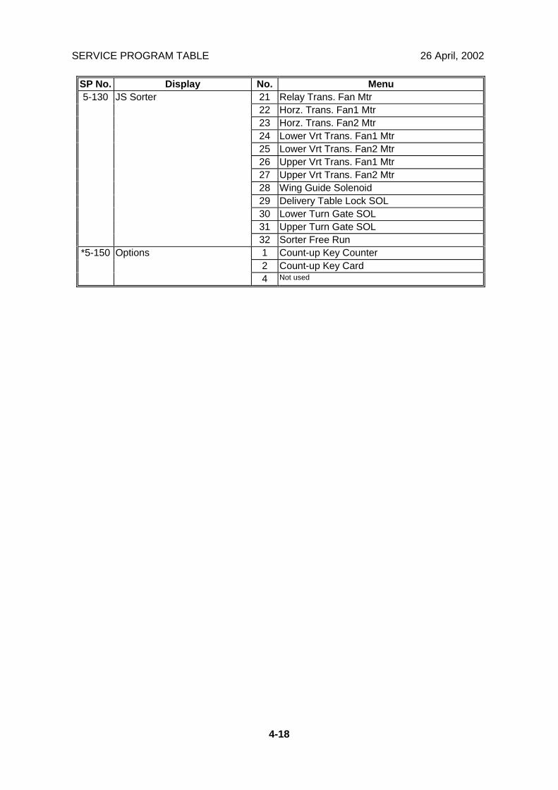
SP No. Display No. Menu21 Relay Trans. Fan Mtr22 Horz. Trans. Fan1 Mtr23 Horz. Trans. Fan2 Mtr24 Lower Vrt Trans. Fan1 Mtr25 Lower Vrt Trans. Fan2 Mtr26 Upper Vrt Trans. Fan1 Mtr27 Upper Vrt Trans. Fan2 Mtr28 Wing Guide Solenoid29 Delivery Table Lock SOL30 Lower Turn Gate SOL31 Upper Turn Gate SOL
5-130 JS Sorter
32 Sorter Free Run1 Count-up Key Counter2 Count-up Key Card
*5-150 Options
4 Not used

26 April, 2002 SERVICE PROGRAM TABLE
4-19
Serv
ice
Tabl
es
6. System AdjustmentNOTE: For model #C244
No. Display No. Menu Function De-fault Setting
1 Main Scan Pos. -Platen
0 -5.0 to 2.0mm
2 Main Scan Position- DF
Side-to-side registrationadjustment; see Note 1.
0 -5.0 to 5.0mm
3 Scan Start Pos. -Platen
0 -2.0 to 5.0mm
4 Scan Start Position -DF
Scanning start lineadjustment; see Note 2.
0 -5.0 to 5.0mm
5 Scanning Speed -Platen
0 -5.0 to 5.0%
6 Scanning Speed -DF
See Note 3.
0 -5.0 to 5.0%
7 Master WritingSpeed
See Note 4. 0 -5.0 to 5.0%
8 Master WritingLength
Do not use in the field. 0 -5.0 to 5.0%
9 Master Main ScanPos
0 -3.0 to 3.0mm
6-1 Scan &Writing
*10 Trail Edge Margin Adjust the trail edge margin 0 0 to 2mm1 Master Making
DensitySee Note 5. 1 0 to 26-2 Master
MakingDensity *2 Master Making
Density -Letter/Photo
2 0 to 2
6-3 DrumMasterClamp
1 Drum Master ClampRegist
See Note 6. 0 -10 to 10mm
1 Master Eject Sensor 2.5 1.5 to 3.0 V2 Drum Master 1
Sensor2.5 1.5 to 3.0 V
3 Drum Master 2Sensor
2.5 1.5 to 3.0 V
4 Master End Sensor 0.8 0.1 to 3.0 V5 Paper Exit Sensor 2.0 1.5 to 3.0 V
6-4 SNVoltages/Thresholds
6 Master Edge Sensor
The use of these SP modesis explained in various partsof the Replacement andAdjustment section.
2.0 1.5 to 3.0 V1 SBU Auto
CalibrationRefer to the Replacementsand Adjustments section.
- -
2 SBU Gain Setting-EVEN
- 0 to 255
3 SBU Gain Setting-ODD
- 0 to 255
4 SBU DC CountSetting-EVEN
- 0 to 255
6-5 SensorBoard Unit
5 SBU DC CountSetting-ODD
Do not adjust.
- 0 to 255

SERVICE PROGRAM TABLE 26 April, 2002
4-20
No. Display No. Menu Function De-fault Setting
6 SBU ReferenceValue
- 0 to 255
7 SBU Offset Value-EVEN
- 0 to 255
6-5 SensorBoard Unit
8 SBU Offset Value-ODD
Do not adjust.
- 0 to 255
1 Letter Mode-MainScan
2 0 to 7
2 Letter Mode-SubScan
1 0 to 7
3 LetterPhoto Mode-Main Scan
0 0 to 7
4 Letter/Photo Mode-Sub Scan
0 0 to 7
5 Photo Mode-MainScan
4 0 to 7
6 Photo Mode-SubScan
4 0 to 7
7 Pencil Mode-MainScan
2 0 to 7
8 Pencil Mode-SubScan
1 0 to 7
9 Tint Mode-MainScan
4 0 to 7
6-6 MTF Filters
10 Tint Mode-Sub Scan
See Note 7.
4 0 to 71 A3 Drum 0 0 to 52 DLT Drum 0 0 to 5
*6-7 DrumMasterLength 3 A4 Drum
Adjust the Drum MasterLengthWhen the original has a solidarea at the trailing edge,increasing this value preventsmaster crinkling. However, ifthe drum is placed in a C593unit, the crinkling may occurbecause the printingmechanism is different.
0 0 to 5
1 FeedPressure StdNor Ppr
3 0 to 6
2 Freq - Normal Paper 5 0 to 63 V Freq - Normal
Paper6 0 to 6
4 FeedPressure StdThick
3 0 to 6
5 Freq - Thick Paper 5 0 to 66 V Freq - Thick
Paper6 0 to 6
7 Feed Pressure StdThin
1 0 to 6
8 Freq - Thin Paper 3 0 to 6
6-9 Paper FeedPressure
9 V Freq - Thin Paper
See Note 8.
5 0 to 6
26 April, 2002 SERVICE PROGRAM TABLE
4-21
Serv
ice
Tabl
es
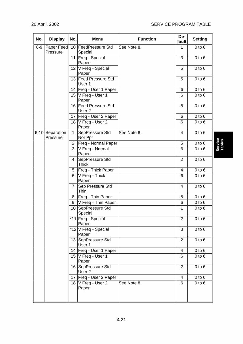
No. Display No. Menu Function De-fault Setting
10 FeedPressure StdSpecial
1 0 to 6
11 Freq - SpecialPaper
3 0 to 6
12 V Freq - SpecialPaper
5 0 to 6
13 Feed Pressure StdUser 1
5 0 to 6
14 Freq - User 1 Paper 6 0 to 615 V Freq - User 1
Paper6 0 to 6
16 Feed Pressure StdUser 2
5 0 to 6
17 Freq - User 2 Paper 6 0 to 6
6-9 Paper FeedPressure
18 V Freq - User 2Paper
See Note 8.
6 0 to 6
1 SepPressure StdNor Ppr
See Note 8. 4 0 to 6
2 Freq - Normal Paper 5 0 to 63 V Freq - Normal
Paper6 0 to 6
4 SepPressure StdThick
2 0 to 6
5 Freq - Thick Paper 4 0 to 66 V Freq - Thick
Paper6 0 to 6
7 Sep Pressure StdThin
4 0 to 6
8 Freq - Thin Paper 5 0 to 69 V Freq - Thin Paper 6 0 to 610 SepPressure Std
Special1 0 to 6
*11 Freq - SpecialPaper
2 0 to 6
*12 V Freq - SpecialPaper
3 0 to 6
13 SepPressure StdUser 1
2 0 to 6
14 Freq - User 1 Paper 4 0 to 615 V Freq - User 1
Paper6 0 to 6
16 SepPressure StdUser 2
2 0 to 6
17 Freq - User 2 Paper 4 0 to 6
6-10 SeparationPressure
18 V Freq - User 2Paper
See Note 8. 6 0 to 6
SERVICE PROGRAM TABLE 26 April, 2002
4-22
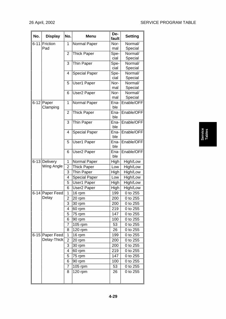
No. Display No. Menu Function De-fault Setting
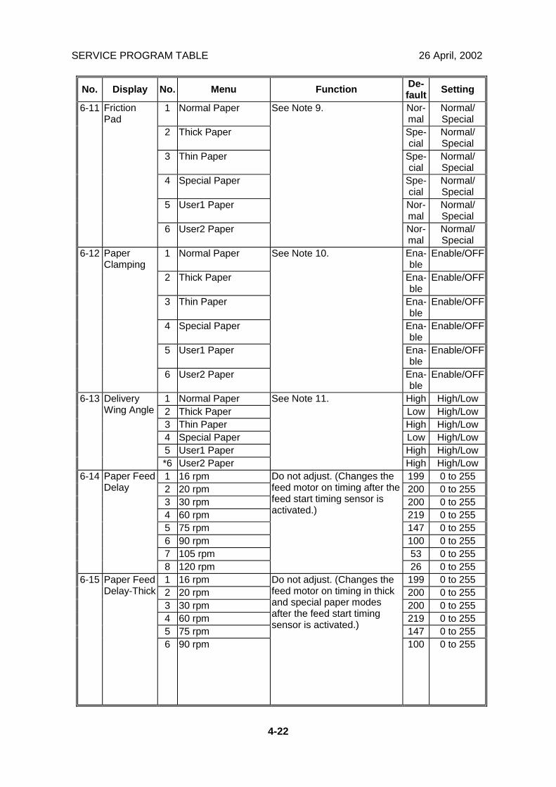
1 Normal Paper Nor-mal
Normal/Special
2 Thick Paper Spe-cial
Normal/Special
3 Thin Paper Spe-cial
Normal/Special
4 Special Paper Spe-cial
Normal/Special
5 User1 Paper Nor-mal
Normal/Special
6-11 FrictionPad
6 User2 Paper
See Note 9.
Nor-mal
Normal/Special
1 Normal Paper Ena-ble
Enable/OFF
2 Thick Paper Ena-ble
Enable/OFF
3 Thin Paper Ena-ble
Enable/OFF
4 Special Paper Ena-ble
Enable/OFF
5 User1 Paper Ena-ble
Enable/OFF
6-12 PaperClamping
6 User2 Paper
See Note 10.
Ena-ble
Enable/OFF
1 Normal Paper High High/Low2 Thick Paper Low High/Low3 Thin Paper High High/Low4 Special Paper Low High/Low5 User1 Paper High High/Low
6-13 DeliveryWing Angle
*6 User2 Paper
See Note 11.
High High/Low1 16 rpm 199 0 to 2552 20 rpm 200 0 to 2553 30 rpm 200 0 to 2554 60 rpm 219 0 to 2555 75 rpm 147 0 to 2556 90 rpm 100 0 to 2557 105 rpm 53 0 to 255
6-14 Paper FeedDelay
8 120 rpm
Do not adjust. (Changes thefeed motor on timing after thefeed start timing sensor isactivated.)
26 0 to 2551 16 rpm 199 0 to 2552 20 rpm 200 0 to 2553 30 rpm 200 0 to 2554 60 rpm 219 0 to 2555 75 rpm 147 0 to 255
6-15 Paper FeedDelay-Thick
6 90 rpm
Do not adjust. (Changes thefeed motor on timing in thickand special paper modesafter the feed start timingsensor is activated.)
100 0 to 255
26 April, 2002 SERVICE PROGRAM TABLE
4-23
Serv
ice
Tabl
es
No. Display No. Menu Function De-fault Setting
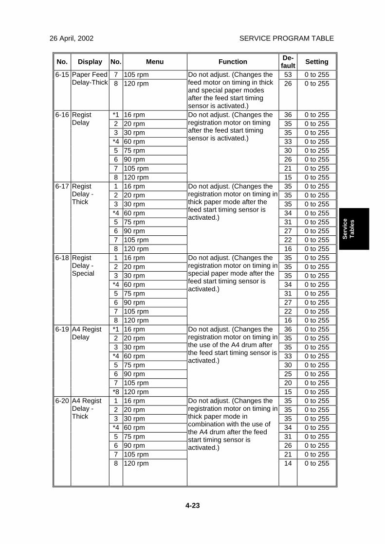
7 105 rpm 53 0 to 2556-15 Paper FeedDelay-Thick 8 120 rpm
Do not adjust. (Changes thefeed motor on timing in thickand special paper modesafter the feed start timingsensor is activated.)
26 0 to 255
*1 16 rpm 36 0 to 2552 20 rpm 35 0 to 2553 30 rpm 35 0 to 255*4 60 rpm 33 0 to 2555 75 rpm 30 0 to 2556 90 rpm 26 0 to 2557 105 rpm 21 0 to 255
6-16 RegistDelay
8 120 rpm
Do not adjust. (Changes theregistration motor on timingafter the feed start timingsensor is activated.)
15 0 to 2551 16 rpm 35 0 to 2552 20 rpm 35 0 to 2553 30 rpm 35 0 to 255*4 60 rpm 34 0 to 2555 75 rpm 31 0 to 2556 90 rpm 27 0 to 2557 105 rpm 22 0 to 255
6-17 RegistDelay -Thick
8 120 rpm
Do not adjust. (Changes theregistration motor on timing inthick paper mode after thefeed start timing sensor isactivated.)
16 0 to 2551 16 rpm 35 0 to 2552 20 rpm 35 0 to 2553 30 rpm 35 0 to 255*4 60 rpm 34 0 to 2555 75 rpm 31 0 to 2556 90 rpm 27 0 to 2557 105 rpm 22 0 to 255
6-18 RegistDelay -Special
8 120 rpm
Do not adjust. (Changes theregistration motor on timing inspecial paper mode after thefeed start timing sensor isactivated.)
16 0 to 255*1 16 rpm 36 0 to 2552 20 rpm 35 0 to 2553 30 rpm 35 0 to 255*4 60 rpm 33 0 to 2555 75 rpm 30 0 to 2556 90 rpm 25 0 to 2557 105 rpm 20 0 to 255
6-19 A4 RegistDelay
*8 120 rpm
Do not adjust. (Changes theregistration motor on timing inthe use of the A4 drum afterthe feed start timing sensor isactivated.)
15 0 to 2551 16 rpm 35 0 to 2552 20 rpm 35 0 to 2553 30 rpm 35 0 to 255*4 60 rpm 34 0 to 2555 75 rpm 31 0 to 2556 90 rpm 26 0 to 2557 105 rpm 21 0 to 255
6-20 A4 RegistDelay -Thick
8 120 rpm
Do not adjust. (Changes theregistration motor on timing inthick paper mode incombination with the use ofthe A4 drum after the feedstart timing sensor isactivated.)
14 0 to 255
SERVICE PROGRAM TABLE 26 April, 2002
4-24
No. Display No. Menu Function De-fault Setting
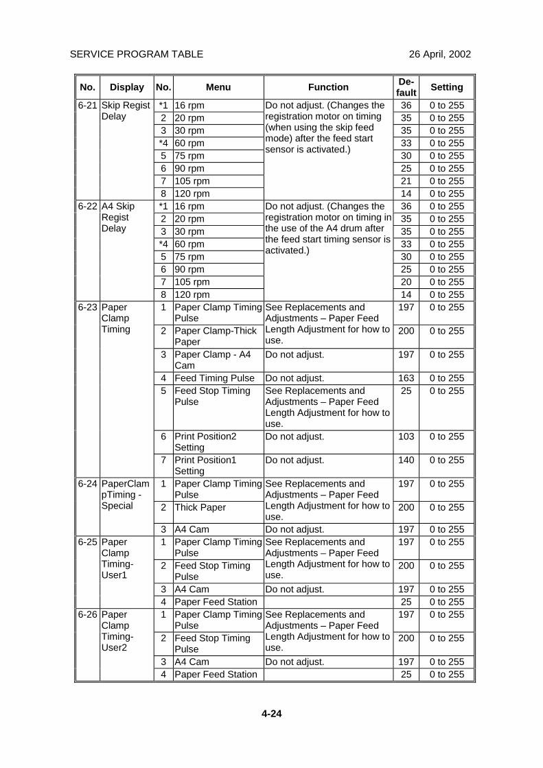
*1 16 rpm 36 0 to 2552 20 rpm 35 0 to 2553 30 rpm 35 0 to 255*4 60 rpm 33 0 to 2555 75 rpm 30 0 to 2556 90 rpm 25 0 to 2557 105 rpm 21 0 to 255
6-21 Skip RegistDelay
8 120 rpm
Do not adjust. (Changes theregistration motor on timing(when using the skip feedmode) after the feed startsensor is activated.)
14 0 to 255*1 16 rpm 36 0 to 2552 20 rpm 35 0 to 2553 30 rpm 35 0 to 255*4 60 rpm 33 0 to 2555 75 rpm 30 0 to 2556 90 rpm 25 0 to 2557 105 rpm 20 0 to 255
6-22 A4 SkipRegistDelay
8 120 rpm
Do not adjust. (Changes theregistration motor on timing inthe use of the A4 drum afterthe feed start timing sensor isactivated.)
14 0 to 2551 Paper Clamp Timing
Pulse197 0 to 255
2 Paper Clamp-ThickPaper
See Replacements andAdjustments – Paper FeedLength Adjustment for how touse.
200 0 to 255
3 Paper Clamp - A4Cam
Do not adjust. 197 0 to 255
4 Feed Timing Pulse Do not adjust. 163 0 to 2555 Feed Stop Timing
PulseSee Replacements andAdjustments – Paper FeedLength Adjustment for how touse.
25 0 to 255
6 Print Position2Setting
Do not adjust. 103 0 to 255
6-23 PaperClampTiming
7 Print Position1Setting
Do not adjust. 140 0 to 255
1 Paper Clamp TimingPulse
197 0 to 255
2 Thick Paper
See Replacements andAdjustments – Paper FeedLength Adjustment for how touse.
200 0 to 255
6-24 PaperClampTiming -Special
3 A4 Cam Do not adjust. 197 0 to 2551 Paper Clamp Timing
Pulse197 0 to 255
2 Feed Stop TimingPulse
See Replacements andAdjustments – Paper FeedLength Adjustment for how touse.
200 0 to 255
3 A4 Cam Do not adjust. 197 0 to 255
6-25 PaperClampTiming-User1
4 Paper Feed Station 25 0 to 2551 Paper Clamp Timing
Pulse197 0 to 255
2 Feed Stop TimingPulse
See Replacements andAdjustments – Paper FeedLength Adjustment for how touse.
200 0 to 255
3 A4 Cam Do not adjust. 197 0 to 255
6-26 PaperClampTiming-User2
4 Paper Feed Station 25 0 to 255
26 April, 2002 SERVICE PROGRAM TABLE
4-25
Serv
ice
Tabl
es
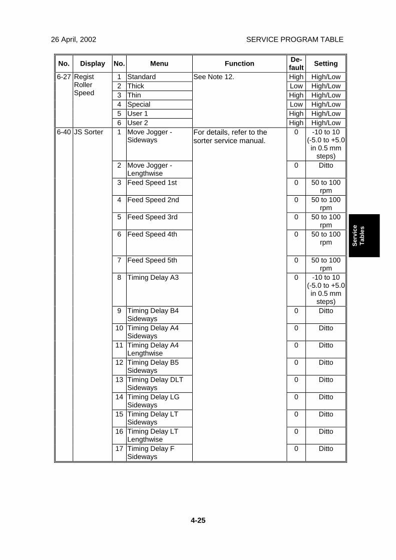
No. Display No. Menu Function De-fault Setting
1 Standard High High/Low2 Thick Low High/Low3 Thin High High/Low4 Special Low High/Low5 User 1 High High/Low
6-27 RegistRollerSpeed
6 User 2
See Note 12.
High High/Low1 Move Jogger -
Sideways0 -10 to 10
(-5.0 to +5.0in 0.5 mm
steps)2 Move Jogger -
Lengthwise0 Ditto
3 Feed Speed 1st 0 50 to 100rpm
4 Feed Speed 2nd 0 50 to 100rpm
5 Feed Speed 3rd 0 50 to 100rpm
6 Feed Speed 4th 0 50 to 100rpm
7 Feed Speed 5th 0 50 to 100rpm
8 Timing Delay A3 0 -10 to 10(-5.0 to +5.0in 0.5 mm
steps)9 Timing Delay B4
Sideways0 Ditto
10 Timing Delay A4Sideways
0 Ditto
11 Timing Delay A4Lengthwise
0 Ditto
12 Timing Delay B5Sideways
0 Ditto
13 Timing Delay DLTSideways
0 Ditto
14 Timing Delay LGSideways
0 Ditto
15 Timing Delay LTSideways
0 Ditto
16 Timing Delay LTLengthwise
0 Ditto
6-40 JS Sorter
17 Timing Delay FSideways
For details, refer to thesorter service manual.
0 Ditto
SERVICE PROGRAM TABLE 26 April, 2002
4-26
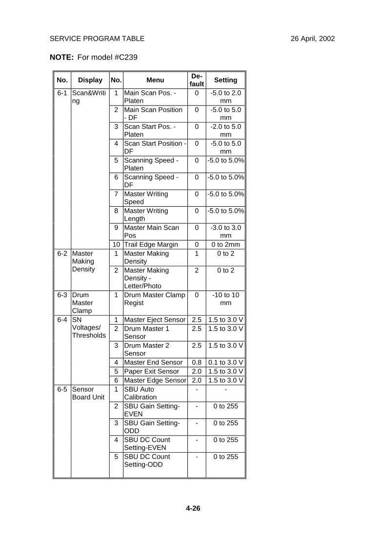
NOTE: For model #C239
No. Display No. Menu De-fault Setting
1 Main Scan Pos. -Platen
0 -5.0 to 2.0mm
2 Main Scan Position- DF
0 -5.0 to 5.0mm
3 Scan Start Pos. -Platen
0 -2.0 to 5.0mm
4 Scan Start Position -DF
0 -5.0 to 5.0mm
5 Scanning Speed -Platen
0 -5.0 to 5.0%
6 Scanning Speed -DF
0 -5.0 to 5.0%
7 Master WritingSpeed
0 -5.0 to 5.0%
8 Master WritingLength
0 -5.0 to 5.0%
9 Master Main ScanPos
0 -3.0 to 3.0mm
6-1 Scan&Writing
10 Trail Edge Margin 0 0 to 2mm1 Master Making
Density1 0 to 26-2 Master
MakingDensity 2 Master Making
Density -Letter/Photo
2 0 to 2
6-3 DrumMasterClamp
1 Drum Master ClampRegist
0 -10 to 10mm
1 Master Eject Sensor 2.5 1.5 to 3.0 V2 Drum Master 1
Sensor2.5 1.5 to 3.0 V
3 Drum Master 2Sensor
2.5 1.5 to 3.0 V
4 Master End Sensor 0.8 0.1 to 3.0 V5 Paper Exit Sensor 2.0 1.5 to 3.0 V
6-4 SNVoltages/Thresholds
6 Master Edge Sensor 2.0 1.5 to 3.0 V1 SBU Auto
Calibration- -
2 SBU Gain Setting-EVEN
- 0 to 255
3 SBU Gain Setting-ODD
- 0 to 255
4 SBU DC CountSetting-EVEN
- 0 to 255
6-5 SensorBoard Unit
5 SBU DC CountSetting-ODD
- 0 to 255
26 April, 2002 SERVICE PROGRAM TABLE
4-27
Serv
ice
Tabl
es
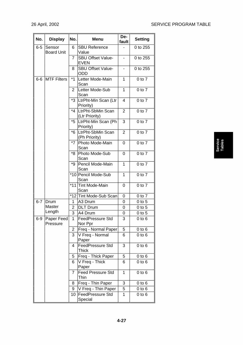
No. Display No. Menu De-fault Setting
6 SBU ReferenceValue
- 0 to 255
7 SBU Offset Value-EVEN
- 0 to 255
6-5 SensorBoard Unit
8 SBU Offset Value-ODD
- 0 to 255
*1 Letter Mode-MainScan
1 0 to 7
2 Letter Mode-SubScan
1 0 to 7
*3 LtrPht-Min Scan (LtrPriority)
4 0 to 7
*4 LtrPht-SbMin Scan(Ltr Priority)
2 0 to 7
*5 LtrPht-Min Scan (PhPriority)
3 0 to 7
*6 LtrPht-SbMin Scan(Ph Priority)
2 0 to 7
*7 Photo Mode-MainScan
0 0 to 7
*8 Photo Mode-SubScan
0 0 to 7
*9 Pencil Mode-MainScan
1 0 to 7
*10 Pencil Mode-SubScan
1 0 to 7
*11 Tint Mode-MainScan
0 0 to 7
6-6 MTF Filters
*12 Tint Mode-Sub Scan 0 0 to 71 A3 Drum 0 0 to 52 DLT Drum 0 0 to 5
6-7 DrumMasterLength 3 A4 Drum 0 0 to 5
1 FeedPressure StdNor Ppr
3 0 to 6
2 Freq - Normal Paper 5 0 to 63 V Freq - Normal
Paper6 0 to 6
4 FeedPressure StdThick
3 0 to 6
5 Freq - Thick Paper 5 0 to 66 V Freq - Thick
Paper6 0 to 6
7 Feed Pressure StdThin
1 0 to 6
8 Freq - Thin Paper 3 0 to 69 V Freq - Thin Paper 5 0 to 6
6-9 Paper FeedPressure
10 FeedPressure StdSpecial
1 0 to 6
SERVICE PROGRAM TABLE 26 April, 2002
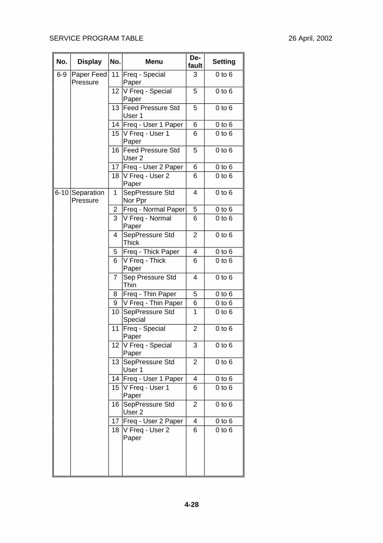
4-28
No. Display No. Menu De-fault Setting
11 Freq - SpecialPaper
3 0 to 6
12 V Freq - SpecialPaper
5 0 to 6
13 Feed Pressure StdUser 1
5 0 to 6
14 Freq - User 1 Paper 6 0 to 615 V Freq - User 1
Paper6 0 to 6
16 Feed Pressure StdUser 2
5 0 to 6
17 Freq - User 2 Paper 6 0 to 6
6-9 Paper FeedPressure
18 V Freq - User 2Paper
6 0 to 6
1 SepPressure StdNor Ppr
4 0 to 6
2 Freq - Normal Paper 5 0 to 63 V Freq - Normal
Paper6 0 to 6
4 SepPressure StdThick
2 0 to 6
5 Freq - Thick Paper 4 0 to 66 V Freq - Thick
Paper6 0 to 6
7 Sep Pressure StdThin
4 0 to 6
8 Freq - Thin Paper 5 0 to 69 V Freq - Thin Paper 6 0 to 610 SepPressure Std
Special1 0 to 6
11 Freq - SpecialPaper
2 0 to 6
12 V Freq - SpecialPaper
3 0 to 6
13 SepPressure StdUser 1
2 0 to 6
14 Freq - User 1 Paper 4 0 to 615 V Freq - User 1
Paper6 0 to 6
16 SepPressure StdUser 2
2 0 to 6
17 Freq - User 2 Paper 4 0 to 6
6-10 SeparationPressure
18 V Freq - User 2Paper
6 0 to 6
26 April, 2002 SERVICE PROGRAM TABLE
4-29
Serv
ice
Tabl
es
No. Display No. Menu De-fault Setting
1 Normal Paper Nor-mal
Normal/Special
2 Thick Paper Spe-cial
Normal/Special
3 Thin Paper Spe-cial
Normal/Special
4 Special Paper Spe-cial
Normal/Special
5 User1 Paper Nor-mal
Normal/Special
6-11 FrictionPad
6 User2 Paper Nor-mal
Normal/Special
1 Normal Paper Ena-ble
Enable/OFF
2 Thick Paper Ena-ble
Enable/OFF
3 Thin Paper Ena-ble
Enable/OFF
4 Special Paper Ena-ble
Enable/OFF
5 User1 Paper Ena-ble
Enable/OFF
6-12 PaperClamping
6 User2 Paper Ena-ble
Enable/OFF
1 Normal Paper High High/Low2 Thick Paper Low High/Low3 Thin Paper High High/Low4 Special Paper Low High/Low5 User1 Paper High High/Low
6-13 DeliveryWing Angle
6 User2 Paper High High/Low1 16 rpm 199 0 to 2552 20 rpm 200 0 to 2553 30 rpm 200 0 to 2554 60 rpm 219 0 to 2555 75 rpm 147 0 to 2556 90 rpm 100 0 to 2557 105 rpm 53 0 to 255
6-14 Paper FeedDelay
8 120 rpm 26 0 to 2551 16 rpm 199 0 to 2552 20 rpm 200 0 to 2553 30 rpm 200 0 to 2554 60 rpm 219 0 to 2555 75 rpm 147 0 to 2556 90 rpm 100 0 to 2557 105 rpm 53 0 to 255
6-15 Paper FeedDelay-Thick
8 120 rpm 26 0 to 255
SERVICE PROGRAM TABLE 26 April, 2002
4-30
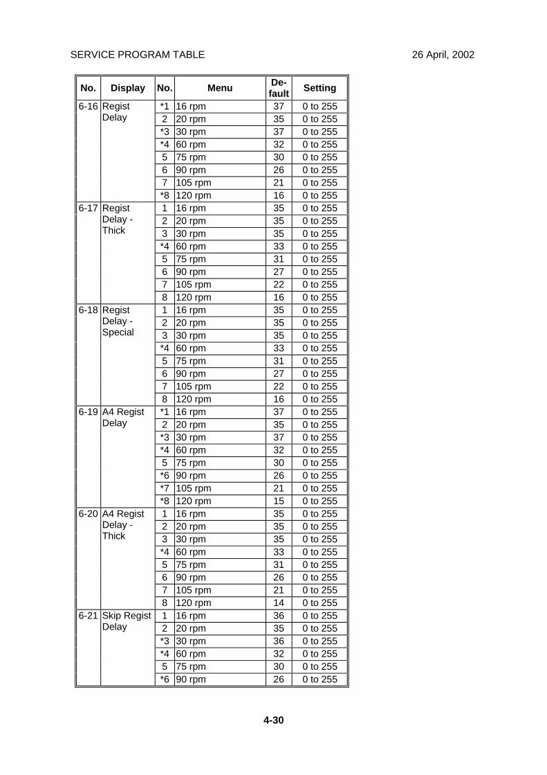
No. Display No. Menu De-fault Setting
*1 16 rpm 37 0 to 2552 20 rpm 35 0 to 255*3 30 rpm 37 0 to 255*4 60 rpm 32 0 to 2555 75 rpm 30 0 to 2556 90 rpm 26 0 to 2557 105 rpm 21 0 to 255
6-16 RegistDelay
*8 120 rpm 16 0 to 2551 16 rpm 35 0 to 2552 20 rpm 35 0 to 2553 30 rpm 35 0 to 255*4 60 rpm 33 0 to 2555 75 rpm 31 0 to 2556 90 rpm 27 0 to 2557 105 rpm 22 0 to 255
6-17 RegistDelay -Thick
8 120 rpm 16 0 to 2551 16 rpm 35 0 to 2552 20 rpm 35 0 to 2553 30 rpm 35 0 to 255*4 60 rpm 33 0 to 2555 75 rpm 31 0 to 2556 90 rpm 27 0 to 2557 105 rpm 22 0 to 255
6-18 RegistDelay -Special
8 120 rpm 16 0 to 255*1 16 rpm 37 0 to 2552 20 rpm 35 0 to 255*3 30 rpm 37 0 to 255*4 60 rpm 32 0 to 2555 75 rpm 30 0 to 255*6 90 rpm 26 0 to 255*7 105 rpm 21 0 to 255
6-19 A4 RegistDelay
*8 120 rpm 15 0 to 2551 16 rpm 35 0 to 2552 20 rpm 35 0 to 2553 30 rpm 35 0 to 255*4 60 rpm 33 0 to 2555 75 rpm 31 0 to 2556 90 rpm 26 0 to 2557 105 rpm 21 0 to 255
6-20 A4 RegistDelay -Thick
8 120 rpm 14 0 to 2551 16 rpm 36 0 to 2552 20 rpm 35 0 to 255*3 30 rpm 36 0 to 255*4 60 rpm 32 0 to 2555 75 rpm 30 0 to 255
6-21 Skip RegistDelay
*6 90 rpm 26 0 to 255
26 April, 2002 SERVICE PROGRAM TABLE
4-31
Serv
ice
Tabl
es
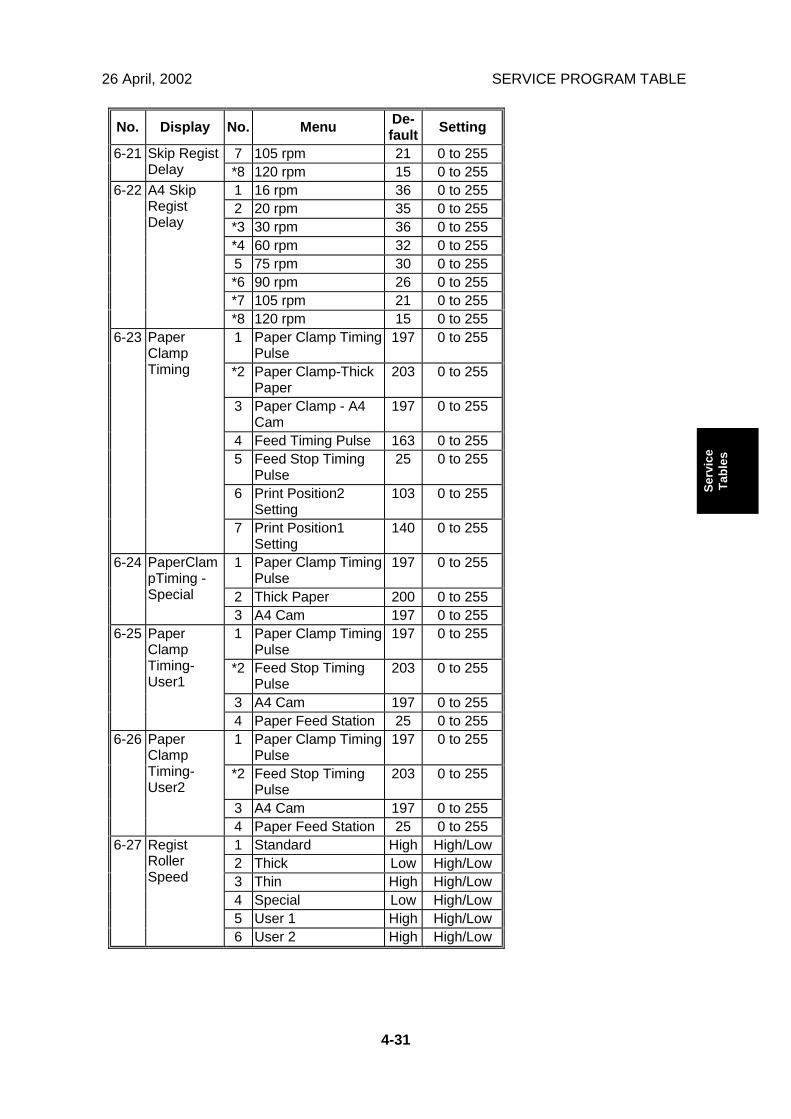
No. Display No. Menu De-fault Setting
7 105 rpm 21 0 to 2556-21 Skip RegistDelay *8 120 rpm 15 0 to 255
1 16 rpm 36 0 to 2552 20 rpm 35 0 to 255*3 30 rpm 36 0 to 255*4 60 rpm 32 0 to 2555 75 rpm 30 0 to 255*6 90 rpm 26 0 to 255*7 105 rpm 21 0 to 255
6-22 A4 SkipRegistDelay
*8 120 rpm 15 0 to 2551 Paper Clamp Timing
Pulse197 0 to 255
*2 Paper Clamp-ThickPaper
203 0 to 255
3 Paper Clamp - A4Cam
197 0 to 255
4 Feed Timing Pulse 163 0 to 2555 Feed Stop Timing
Pulse25 0 to 255
6 Print Position2Setting
103 0 to 255
6-23 PaperClampTiming
7 Print Position1Setting
140 0 to 255
1 Paper Clamp TimingPulse
197 0 to 255
2 Thick Paper 200 0 to 255
6-24 PaperClampTiming -Special
3 A4 Cam 197 0 to 2551 Paper Clamp Timing
Pulse197 0 to 255
*2 Feed Stop TimingPulse
203 0 to 255
3 A4 Cam 197 0 to 255
6-25 PaperClampTiming-User1
4 Paper Feed Station 25 0 to 2551 Paper Clamp Timing
Pulse197 0 to 255
*2 Feed Stop TimingPulse
203 0 to 255
3 A4 Cam 197 0 to 255
6-26 PaperClampTiming-User2
4 Paper Feed Station 25 0 to 2551 Standard High High/Low2 Thick Low High/Low3 Thin High High/Low4 Special Low High/Low5 User 1 High High/Low
6-27 RegistRollerSpeed
6 User 2 High High/Low
SERVICE PROGRAM TABLE 26 April, 2002
4-32
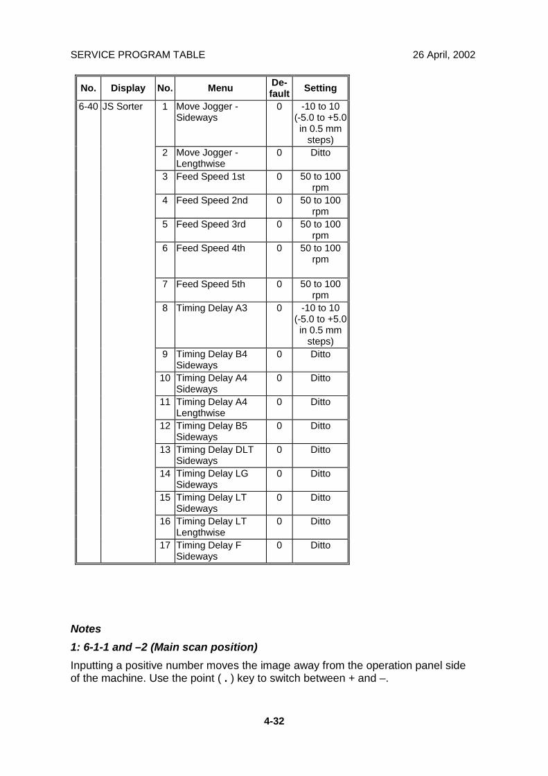
No. Display No. Menu De-fault Setting
1 Move Jogger -Sideways
0 -10 to 10(-5.0 to +5.0in 0.5 mm
steps)2 Move Jogger -
Lengthwise0 Ditto
3 Feed Speed 1st 0 50 to 100rpm
4 Feed Speed 2nd 0 50 to 100rpm
5 Feed Speed 3rd 0 50 to 100rpm
6 Feed Speed 4th 0 50 to 100rpm
7 Feed Speed 5th 0 50 to 100rpm
8 Timing Delay A3 0 -10 to 10(-5.0 to +5.0in 0.5 mm
steps)9 Timing Delay B4
Sideways0 Ditto
10 Timing Delay A4Sideways
0 Ditto
11 Timing Delay A4Lengthwise
0 Ditto
12 Timing Delay B5Sideways
0 Ditto
13 Timing Delay DLTSideways
0 Ditto
14 Timing Delay LGSideways
0 Ditto
15 Timing Delay LTSideways
0 Ditto
16 Timing Delay LTLengthwise
0 Ditto
6-40 JS Sorter
17 Timing Delay FSideways
0 Ditto
Notes1: 6-1-1 and –2 (Main scan position)Inputting a positive number moves the image away from the operation panel sideof the machine. Use the point ( . ) key to switch between + and –.
26 April, 2002 SERVICE PROGRAM TABLE
4-33
Serv
ice
Tabl
es
2: 6-1-3 and –4 (Scan start position)Inputting a positive number moves the image away from the leading edge of theprinter paper. Use the point ( . ) key to switch between + and –.
3: 6-1-5 and -6 (Scanning speed)Inputting a positive value stretches the image on the master. Inputting a negativevalue shrinks it. Use the point ( . ) key to switch between + and –.
4: 6-1-7 (Master writing speed)This changes the master feed motor speed.Inputting a positive value stretches the image on the master. Inputting a negativevalue shrinks it. Use the point ( . ) key to switch between + and –.Normally, do not use this SP mode to adjust the vertical magnification. Use it only ifthe vertical magnification is not satisfactory by adjusting Scanning Speed (SP6-1-5and -6).
5: 6-2-1 (Master making density)0: Pale, 1: Normal, 2: DarkThe default is 1: Normal. Changing this moves the user”s image density settings upor down one notch.
6: 6-3-1 (Drum master clamper registration)This determines how far after the leading edge the master is clamped.A larger value clamps the master further away from the leading edge, and movesthe image closer to the leading edge of the paper.Do not use this SP to adjust leading edge registration. Use SP6-1-3 and -4 for that.
SERVICE PROGRAM TABLE 26 April, 2002
4-34
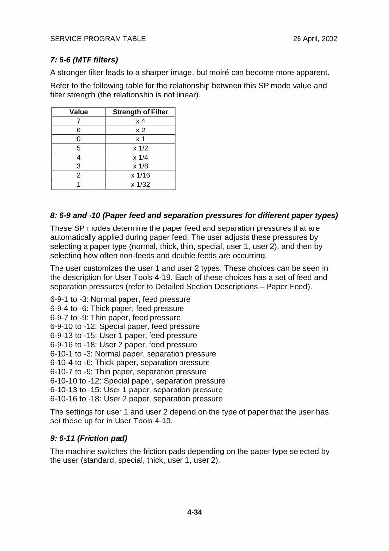
7: 6-6 (MTF filters)A stronger filter leads to a sharper image, but moiré can become more apparent.Refer to the following table for the relationship between this SP mode value andfilter strength (the relationship is not linear).
Value Strength of Filter7 x 46 x 20 x 15 x 1/24 x 1/43 x 1/82 x 1/161 x 1/32
8: 6-9 and -10 (Paper feed and separation pressures for different paper types)These SP modes determine the paper feed and separation pressures that areautomatically applied during paper feed. The user adjusts these pressures byselecting a paper type (normal, thick, thin, special, user 1, user 2), and then byselecting how often non-feeds and double feeds are occurring.The user customizes the user 1 and user 2 types. These choices can be seen inthe description for User Tools 4-19. Each of these choices has a set of feed andseparation pressures (refer to Detailed Section Descriptions – Paper Feed).6-9-1 to -3: Normal paper, feed pressure6-9-4 to -6: Thick paper, feed pressure6-9-7 to -9: Thin paper, feed pressure6-9-10 to -12: Special paper, feed pressure6-9-13 to -15: User 1 paper, feed pressure6-9-16 to -18: User 2 paper, feed pressure6-10-1 to -3: Normal paper, separation pressure6-10-4 to -6: Thick paper, separation pressure6-10-7 to -9: Thin paper, separation pressure6-10-10 to -12: Special paper, separation pressure6-10-13 to -15: User 1 paper, separation pressure6-10-16 to -18: User 2 paper, separation pressureThe settings for user 1 and user 2 depend on the type of paper that the user hasset these up for in User Tools 4-19.
9: 6-11 (Friction pad)The machine switches the friction pads depending on the paper type selected bythe user (standard, special, thick, user 1, user 2).
26 April, 2002 SERVICE PROGRAM TABLE
4-35
Serv
ice
Tabl
es
10: 6-12 (Paper clamping)Whether the machine clamps the paper or not depends on the paper type selectedby the user (standard, special, thick, user 1, user 2).The settings for user 1 and user 2 depend on the type of paper that the user hasset these up for in User Tools 4-19.
11: 6-13 (Paper delivery table wing angle)The machine lifts or lowers the wings depending on the paper type selected by theuser (standard, special, thick, user 1, user 2).The settings for user 1 and user 2 depend on the type of paper that the user hasset these up for in User Tools 4-19.
12: 6-27 (Regist roller speed)For an accurate paper registration, the machine lowers the registration rollerrotation speed depending on the paper type selected by the user (standard,special, thick, user 1, user 2). Usually, the “high” speed setting (3% higher than thelow) results in the better registration. However, when thick paper is used, it shouldbe lowered because thick paper strongly pushes the paper clamper. This causes afriction to the smooth rotation of the pressure cylinder due to a play in the cylinder”sdrive transmission.The settings for user 1 and user 2 depend on the type of paper that the user hasset these up for in User Tools 4-19.
SERVICE PROGRAM TABLE 26 April, 2002
4-36
7. Memory Data ClearSP No. Display No. Menu
1 Factory Settings2 User Custom Default3 User Program4 Make-up Pattern
7-1 Memory Clear
5 Reset Sales Mode Flags1 Total Print7-2 Counter Clear2 Jam/Error Logging1 User Code7-3 Code Clear2 Key Operator Code1 Feed Pressure2 Separation Pressure3 Friction Pad Settings4 Wing Guide Angle5 Feed Control Data
7-4 Reset Paper Feed Systems
6 Feed Control Pulse7-5 Reset Image Adjustments 1 MTF Filter Settings7-6 Reset Option Settings 1 JS Sorter Settings
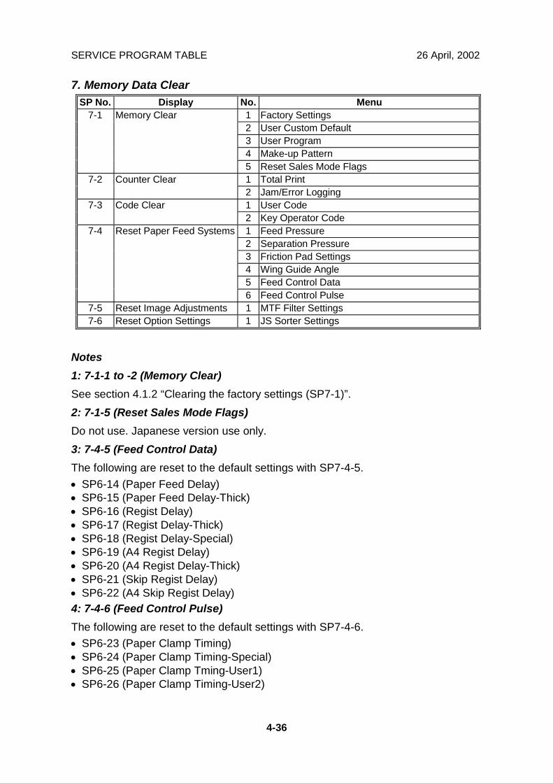
Notes1: 7-1-1 to -2 (Memory Clear)See section 4.1.2 “Clearing the factory settings (SP7-1)”.2: 7-1-5 (Reset Sales Mode Flags)Do not use. Japanese version use only.3: 7-4-5 (Feed Control Data)The following are reset to the default settings with SP7-4-5.• SP6-14 (Paper Feed Delay)• SP6-15 (Paper Feed Delay-Thick)• SP6-16 (Regist Delay)• SP6-17 (Regist Delay-Thick)• SP6-18 (Regist Delay-Special)• SP6-19 (A4 Regist Delay)• SP6-20 (A4 Regist Delay-Thick)• SP6-21 (Skip Regist Delay)• SP6-22 (A4 Skip Regist Delay)4: 7-4-6 (Feed Control Pulse)The following are reset to the default settings with SP7-4-6.• SP6-23 (Paper Clamp Timing)• SP6-24 (Paper Clamp Timing-Special)• SP6-25 (Paper Clamp Tming-User1)• SP6-26 (Paper Clamp Timing-User2)

26 April, 2002 SERVICE PROGRAM TABLE
4-37
Serv
ice
Tabl
es
8. System TestSP No. Display No. Menu Setting
1 All Logging Data -2 User Code Counters Only -3 Jam Counters Only -4 SC Counters Only -5 Jams/Errors Details -6 User's Items Only -7 User Tools-Standard -8 User Tools-Class -9 Basic Settings Printout -
10 Input Test Item Printout -11 Output Test Item Printout -12 All System Adjustment -13 Paper Feed Adjustments -
8-1 Data Printout
14 Option Adjustment Print -1 Load Program -2 Load Program - Program Data -3 Load Program - Font Data -
8-2 DownloadProgram
4 Load Program - Except M orig -8-3 Upload Program 1 Upload Program -
1 TH Test Patterns 0: Grid1: Vertical2: Horiz grey3: Vert grey4: 16 greys5: Cross6: Diag grid7: 256 greys8: 64 greys
8-5 TH Test Patterns
2 Master Makeup Pattern 1 to 401 Scanner Free Run/Mag. 50 to 200%8-6 Free Run -
Scanner/ADF 2 ADF Free Run/Mag. 50 to 200%1 APS Sensor Check Mode -8-7 Other Tests2 Not used -
Notes1: 8-2-1 (Load Program)This upgrades all the firmware using a flash memory card.NOTE: This deletes all user data such as stored images.2: 8-2-2 (Load Program-Program Data)This upgrades the program area data in the firmware using a flash memory card.

SERVICE PROGRAM TABLE 26 April, 2002
4-38
3: 8-2-3 (Load Program-Font Data)This upgrades the font data in the firmware using a flash memory card.4: 8-2-4 (Load Program-Except M Orig)This upgrades all data in the firmware except user area data using a flash memorycard.It is better to use this SP mode when upgrading the firmware.See section “4.1.3 Load Program (SP8-2)”.
9. Printer ControllerSP No. Display No. Menu Default Setting
1 HEX Dump Print Disable Disable/enable2 Service Summary 1
Print- -
3 Service Summary 2Print
- -
4 Parallel Loop-Back Test - -
9-1 Test Mode
5 Self-diagnostic Mode - -1 Config data - -2 Controller NVRAM - -
9-2 Clear Mode
3 NIB NVRAM - -1 Load Program-System - -9-3 Load Program2 Load Program-NIB - -
NOTE: For details, refer to the C607 manual.
26 April, 2002 SERVICE PROGRAM TABLE
4-39
Serv
ice
Tabl
es
4.1.1 CLEARING THE FACTORY SETTINGS (SP7-1)
!CAUTIONPerforming "Clear factory settings" (SP7-1) resets a part of the settingsstored in the RAM to their default settings. Normally, this SP mode shouldnot be used. This procedure is required only after replacing the RAM on theMPU or when the machine malfunctions due to a damaged RAM.
NOTE: 1) The following are not reset or cleared even after doing "Clearfactory settings" (SP7-1-1).• SP 2-4: All destination settings• SP 3-1-1: Serial number• SP 3-1-7: Date• SP 6- All :All system adjustment settings• User Tools 1-5: Select Language on LCD
2) The following are reset to the default settings with "Clear usercode counters only" (SP7-1-2).• SP 2-1: All default user settings• User Tools 3-1: Paper type• User Tools 3-2: Image density level• User Tools 3-3: Original mode• User Tools 3-8: Contrast level for Photo mode• User Tools 3-9: Screen image for Photo mode• User Tools 3-12: Magnification ratio• User Tools 4-1: Auto cycle On/Off
1. Print lists of SP data in order to restore the settings later.NOTE: All system parameter lists can be printed using SP8-1.
2. Select an item from the SP7-1 menu.3. Press the Enter (#) key while holding the “0” key.
NOTE: When the sequence is successful, “Cleared” is displayed.

SERVICE PROGRAM TABLE 26 April, 2002
4-40
4.1.2 LOAD PROGRAM (SP8-2)
The firmware in the flash ROM on the MPU can be upgraded using a flash memorycard, as follows.
NOTE: Using SP8-3, the current firmware in the MPU can be uploaded to a flashmemory card.
1. Before downloading new software, check the current version with SP1-19-7.2. Turn off the main switch and disconnect the power plug.3. Remove the cover [A].4. Plug the flash memory card [B] into the connector on the MPU.5. Connect the power plug and turn on the main switch.6. Access SP8-2-4 and press the OK key. Press the Enter (#) key to start
downloading (the LCD displays 'Processing').7. After completing the download (the LCD displays 'Completed'), leave the SP
mode.NOTE: It takes approximately 2.5 minutes to complete.
8. Turn off the main switch, and then remove the flash memory card.9. Turn on the main switch, then enter the SP mode again and check the updated
ROM version with SP1-19-7.
C244S509.WMF
[A]
[B]
26 April, 2002 MAINTENANCE TABLE
5-1
Prev
entiv
eM
aint
enan
ce
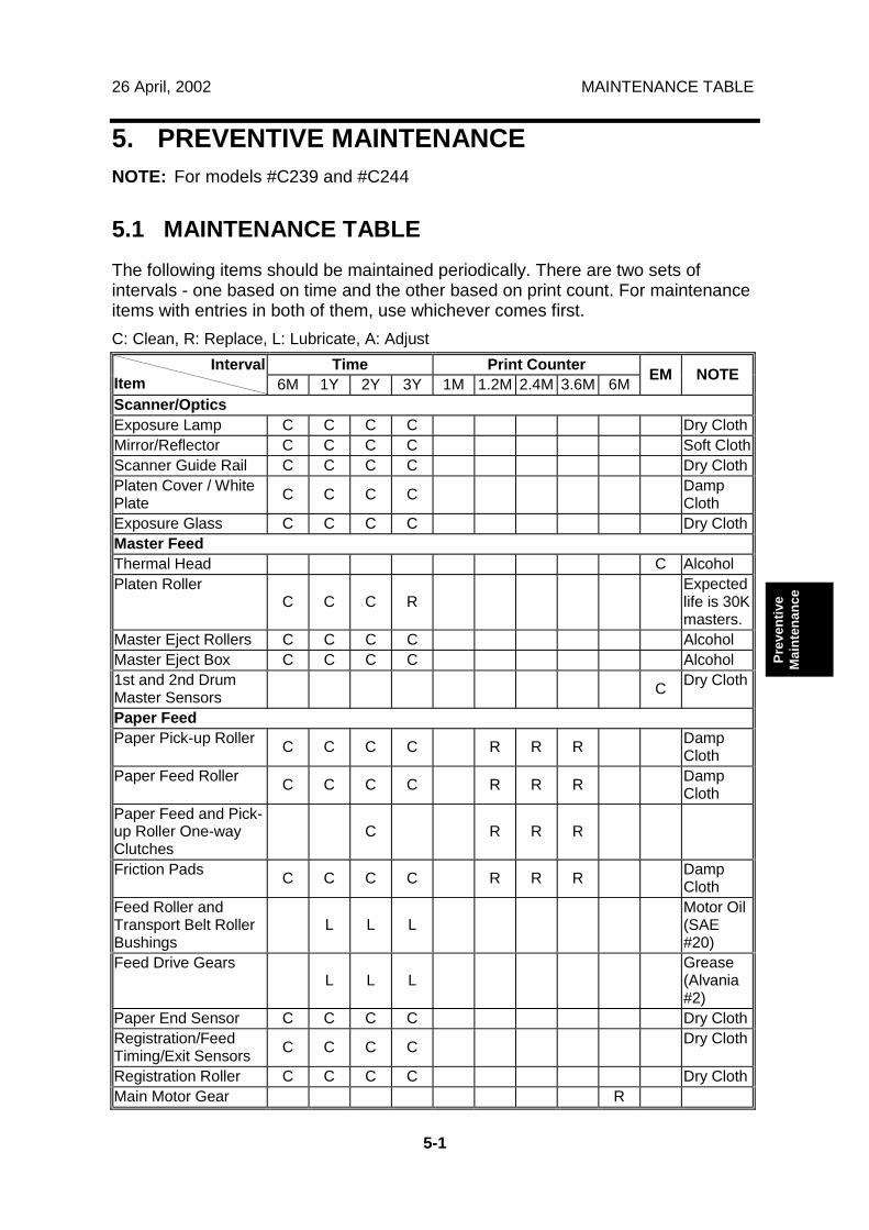
5. PREVENTIVE MAINTENANCENOTE: For models #C239 and #C244
5.1 MAINTENANCE TABLEThe following items should be maintained periodically. There are two sets ofintervals - one based on time and the other based on print count. For maintenanceitems with entries in both of them, use whichever comes first.C: Clean, R: Replace, L: Lubricate, A: Adjust
Time Print CounterIntervalItem 6M 1Y 2Y 3Y 1M 1.2M 2.4M 3.6M 6M EM NOTE
Scanner/OpticsExposure Lamp C C C C Dry ClothMirror/Reflector C C C C Soft ClothScanner Guide Rail C C C C Dry ClothPlaten Cover / WhitePlate C C C C Damp
ClothExposure Glass C C C C Dry ClothMaster FeedThermal Head C AlcoholPlaten Roller
C C C RExpectedlife is 30Kmasters.
Master Eject Rollers C C C C AlcoholMaster Eject Box C C C C Alcohol1st and 2nd DrumMaster Sensors C Dry Cloth
Paper FeedPaper Pick-up Roller C C C C R R R Damp
ClothPaper Feed Roller C C C C R R R Damp
ClothPaper Feed and Pick-up Roller One-wayClutches
C R R R
Friction Pads C C C C R R R DampCloth
Feed Roller andTransport Belt RollerBushings
L L LMotor Oil(SAE#20)
Feed Drive GearsL L L
Grease(Alvania#2)
Paper End Sensor C C C C Dry ClothRegistration/FeedTiming/Exit Sensors C C C C Dry Cloth
Registration Roller C C C C Dry ClothMain Motor Gear R
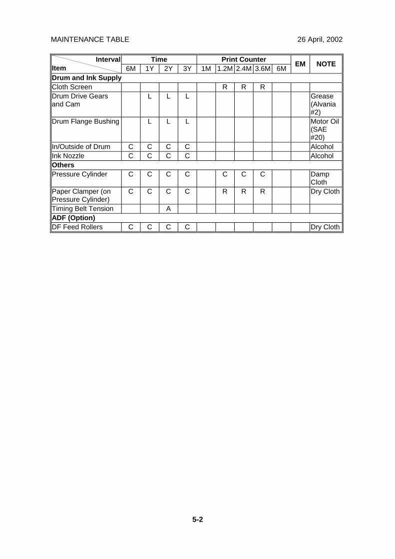
MAINTENANCE TABLE 26 April, 2002
5-2
Time Print CounterIntervalItem 6M 1Y 2Y 3Y 1M 1.2M 2.4M 3.6M 6M EM NOTE
Drum and Ink SupplyCloth Screen R R RDrum Drive Gearsand Cam
L L L Grease(Alvania#2)
Drum Flange Bushing L L L Motor Oil(SAE#20)
In/Outside of Drum C C C C AlcoholInk Nozzle C C C C AlcoholOthersPressure Cylinder C C C C C C C Damp
ClothPaper Clamper (onPressure Cylinder)
C C C C R R R Dry Cloth
Timing Belt Tension AADF (Option)DF Feed Rollers C C C C Dry Cloth
26 April, 2002 MASTER FEED SECTION
6-1
Rep
lace
men
tA
djus
tmen
t
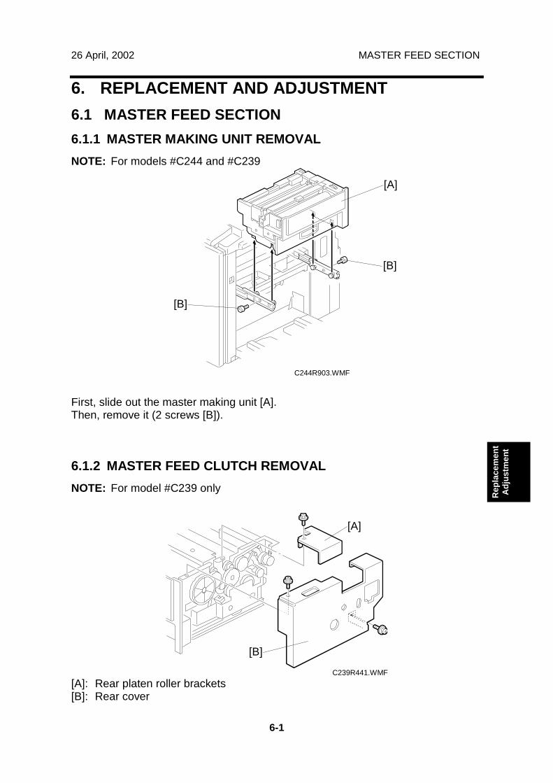
6. REPLACEMENT AND ADJUSTMENT6.1 MASTER FEED SECTION6.1.1 MASTER MAKING UNIT REMOVALNOTE: For models #C244 and #C239
First, slide out the master making unit [A].Then, remove it (2 screws [B]).
6.1.2 MASTER FEED CLUTCH REMOVALNOTE: For model #C239 only
[A]: Rear platen roller brackets[B]: Rear cover
C244R903.WMF
C239R441.WMF
[A]
[B]
[B]
[A]
[B]
MASTER FEED SECTION 26 April, 2002
6-2
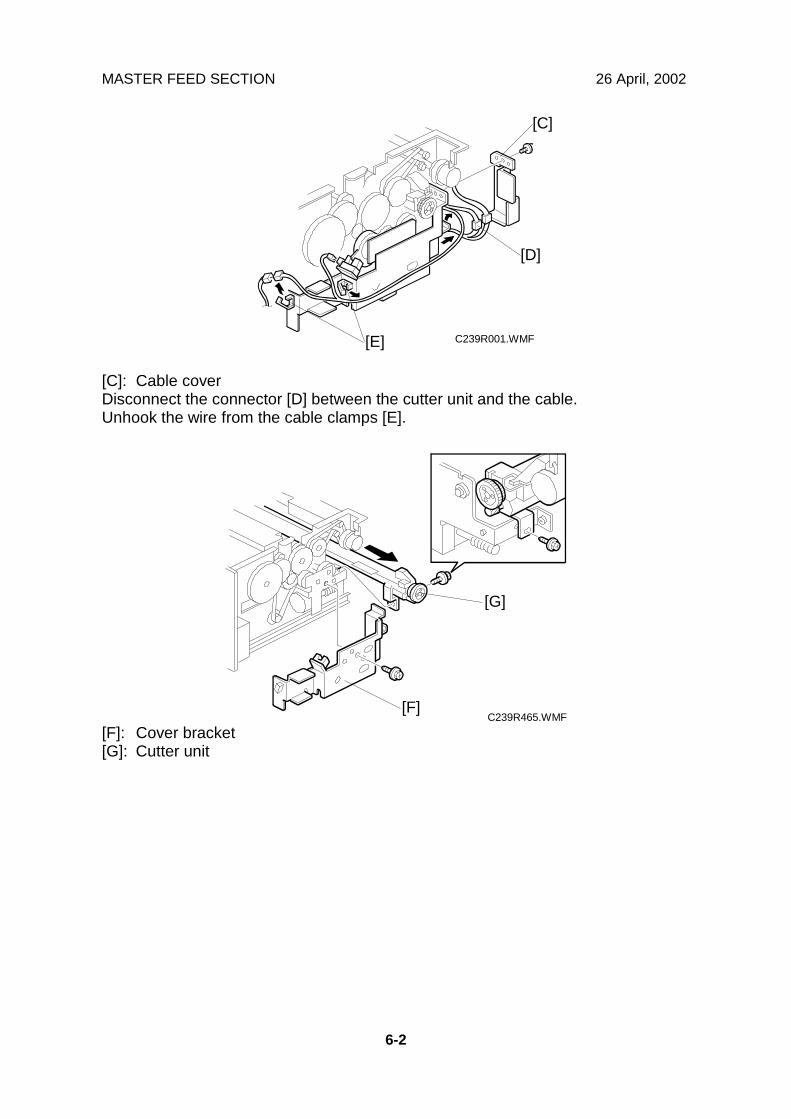
[C]: Cable coverDisconnect the connector [D] between the cutter unit and the cable.Unhook the wire from the cable clamps [E].
[F]: Cover bracket[G]: Cutter unit
C239R001.WMF
C239R465.WMF
[C]
[D]
[E]
[F]
[G]
26 April, 2002 MASTER FEED SECTION
6-3
Rep
lace
men
tA
djus
tmen
t
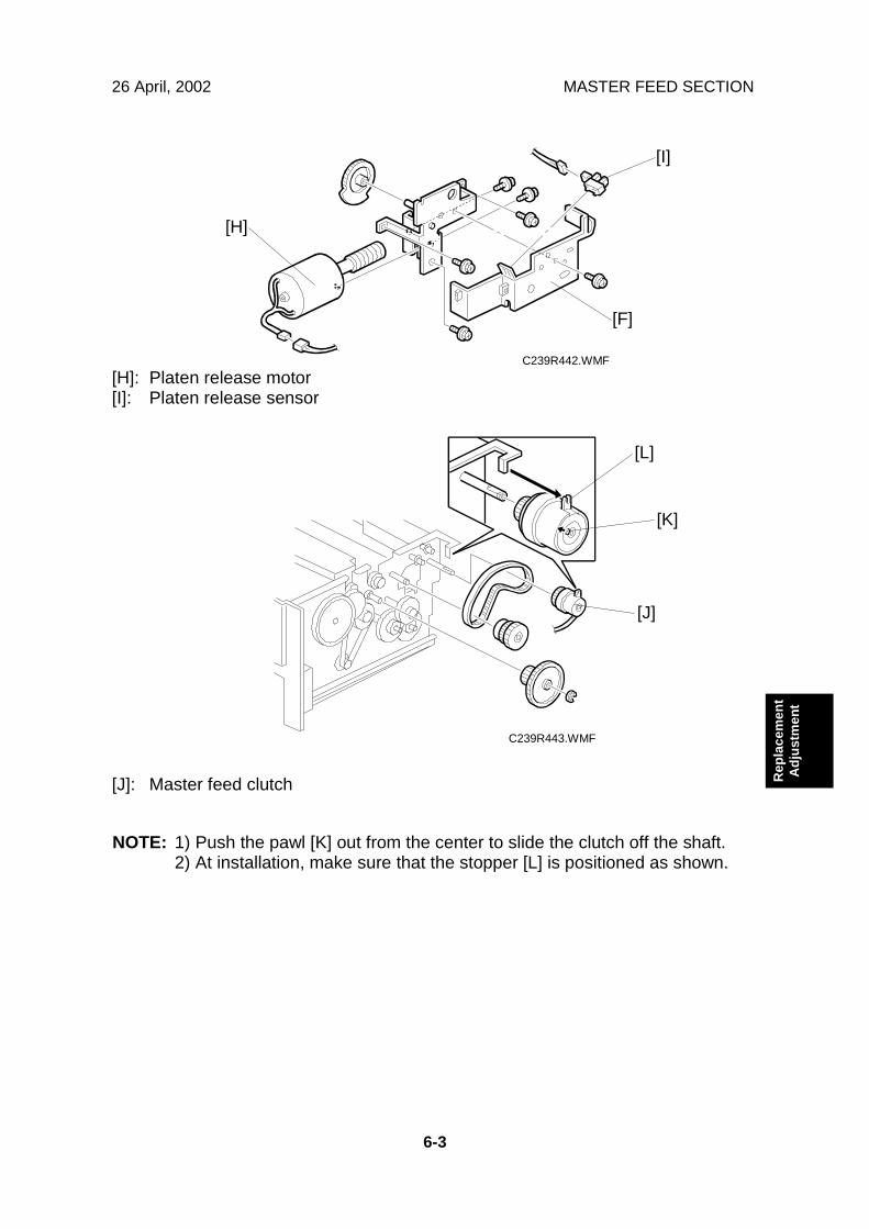
[H]: Platen release motor[I]: Platen release sensor
[J]: Master feed clutch
NOTE: 1) Push the pawl [K] out from the center to slide the clutch off the shaft.2) At installation, make sure that the stopper [L] is positioned as shown.
C239R442.WMF
C239R443.WMF
[F]
[H]
[I]
[J]
[K]
[L]
MASTER FEED SECTION 26 April, 2002
6-4
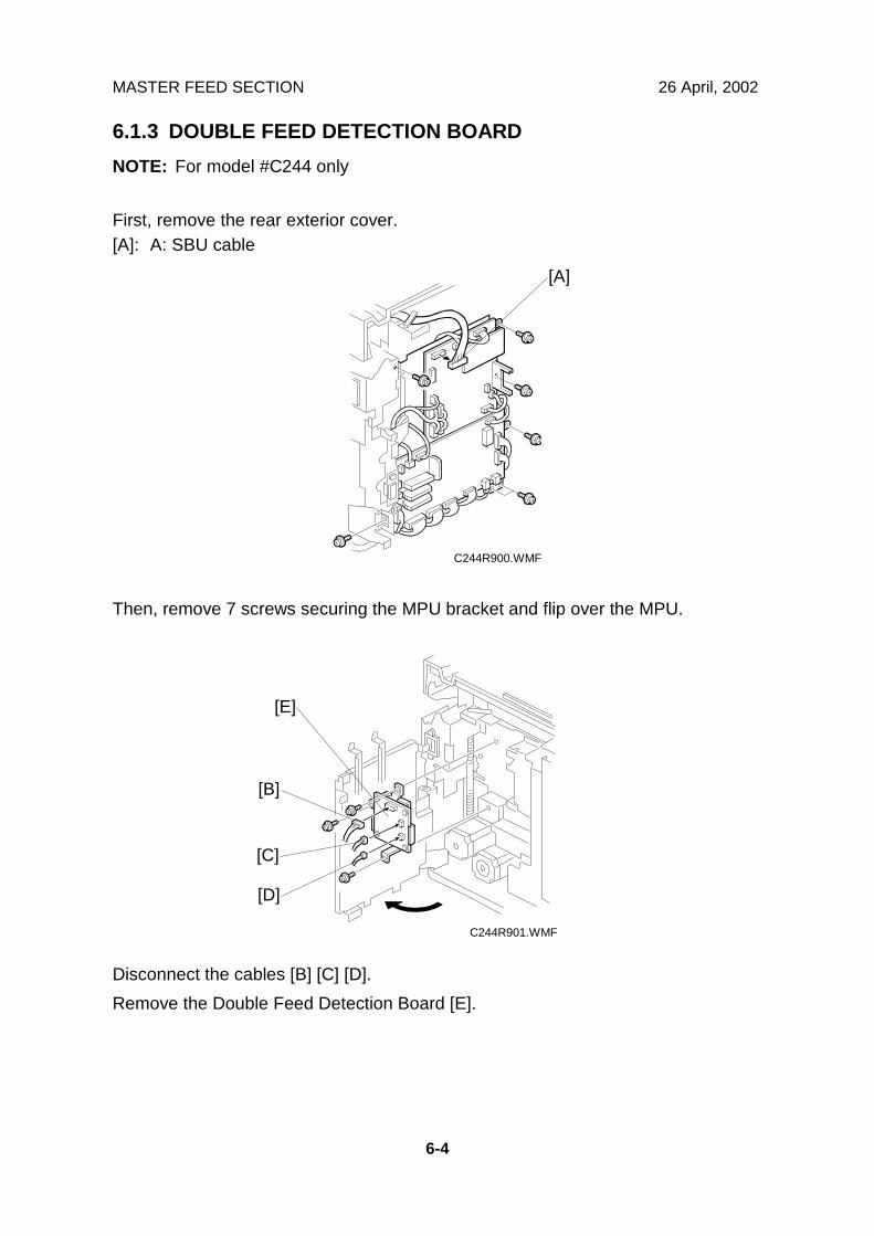
6.1.3 DOUBLE FEED DETECTION BOARDNOTE: For model #C244 only
First, remove the rear exterior cover.[A]: A: SBU cable
Then, remove 7 screws securing the MPU bracket and flip over the MPU.
Disconnect the cables [B] [C] [D].Remove the Double Feed Detection Board [E].
C244R900.WMF
C244R901.WMF
[B]
[C]
[D]
[E]
[A]
26 April, 2002 MASTER FEED SECTION
6-5
Rep
lace
men
tA
djus
tmen
t
6.1.4 DOUBLE FEED SENSOR ADJUSTMENTNOTE: For model #C244 only
Purpose: To ensure that the sensor detects paper double feeds.Procedure:
1. Turn on the main switch.
2. Feed a sheet of the customer’s typicalprint paper from the paper feed table intothe machine until the leading edge runsagainst the feed roller [A].
3. Turn VR101 [B] clockwise until LED101[C] on the double feed detection boardlights.
4. Turn VR101 [B] counterclockwise untilboth LED101 [C] and LED102 [D] light up.
5. Turn VR101 [B] counterclockwise untilLED102 [D] light off.
C244R904.WMF
C244R902.WMF
[A]
[B]
[C][D]
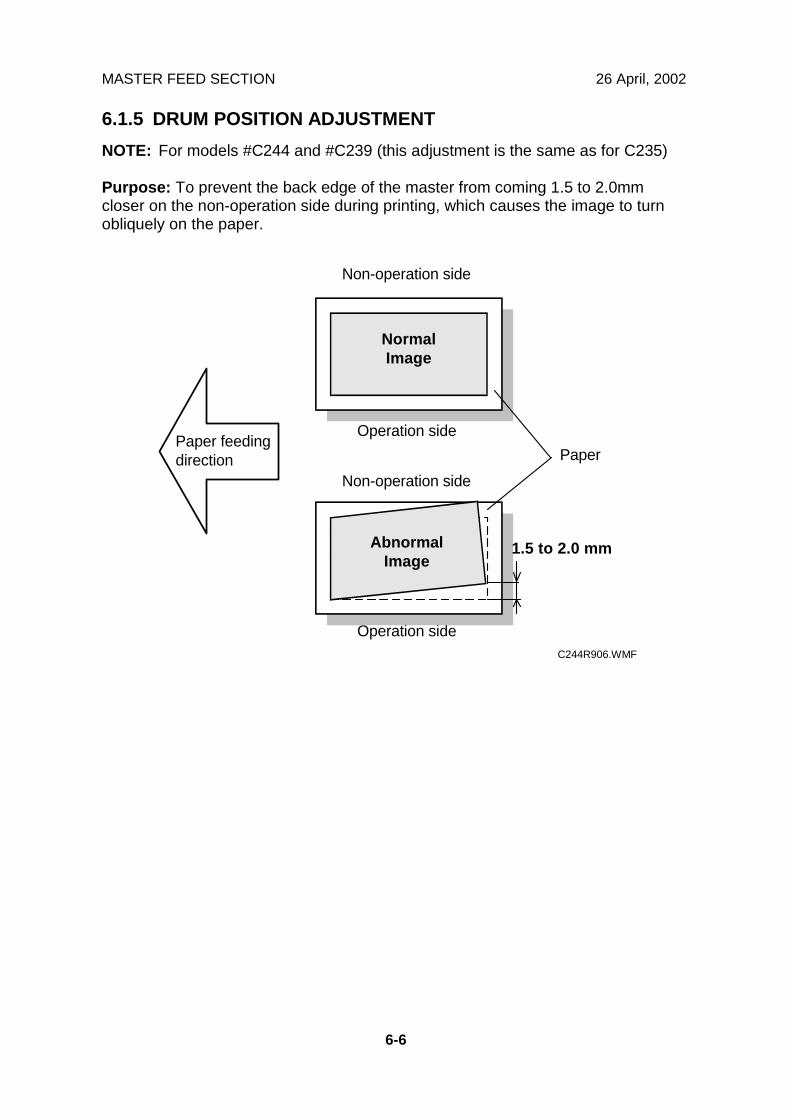
MASTER FEED SECTION 26 April, 2002
6-6
6.1.5 DRUM POSITION ADJUSTMENTNOTE: For models #C244 and #C239 (this adjustment is the same as for C235)
Purpose: To prevent the back edge of the master from coming 1.5 to 2.0mmcloser on the non-operation side during printing, which causes the image to turnobliquely on the paper.
Paper
Non-operation side
Operation side
1.5 to 2.0 mm
Operation side
Non-operation side
Paper feedingdirection
NormalImage
AbnormalImage
C244R906.WMF
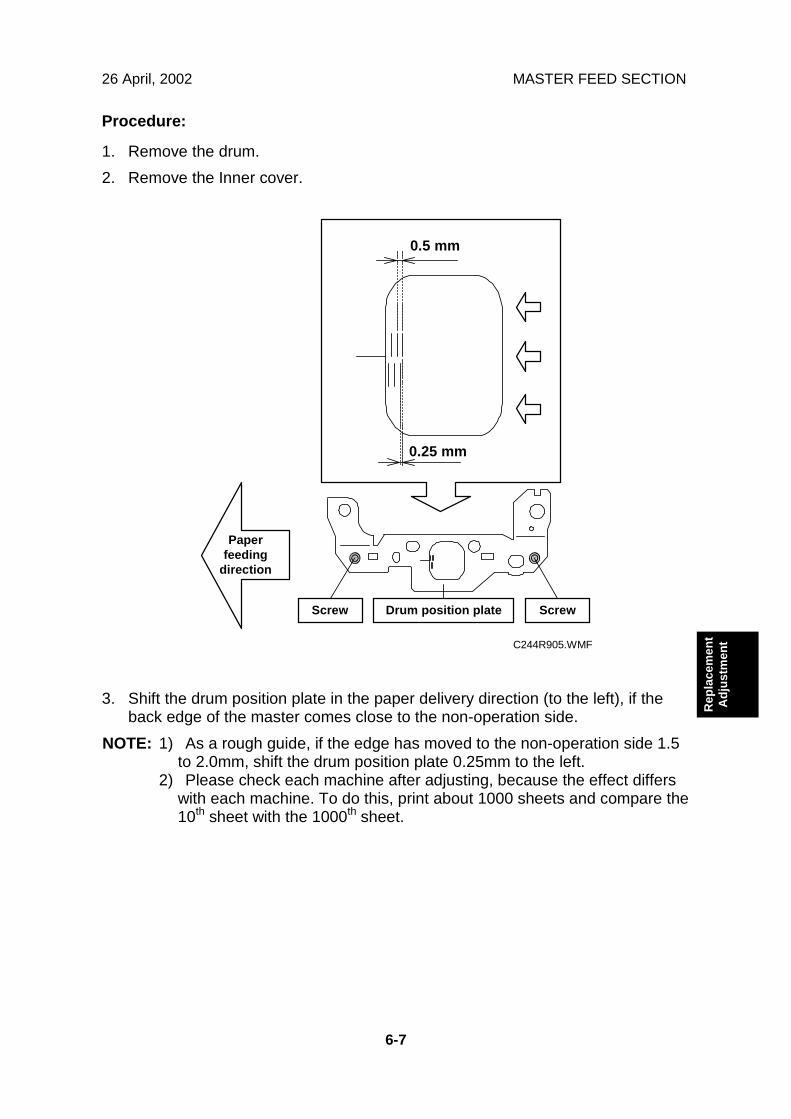
26 April, 2002 MASTER FEED SECTION
6-7
Rep
lace
men
tA
djus
tmen
t
Procedure:
1. Remove the drum.2. Remove the Inner cover.
3. Shift the drum position plate in the paper delivery direction (to the left), if theback edge of the master comes close to the non-operation side.
NOTE: 1) As a rough guide, if the edge has moved to the non-operation side 1.5to 2.0mm, shift the drum position plate 0.25mm to the left.
2) Please check each machine after adjusting, because the effect differswith each machine. To do this, print about 1000 sheets and compare the10th sheet with the 1000th sheet.
ScrewScrew
Paperfeeding
direction
0.5 mm
0.25 mm
Drum position plate
C244R905.WMF
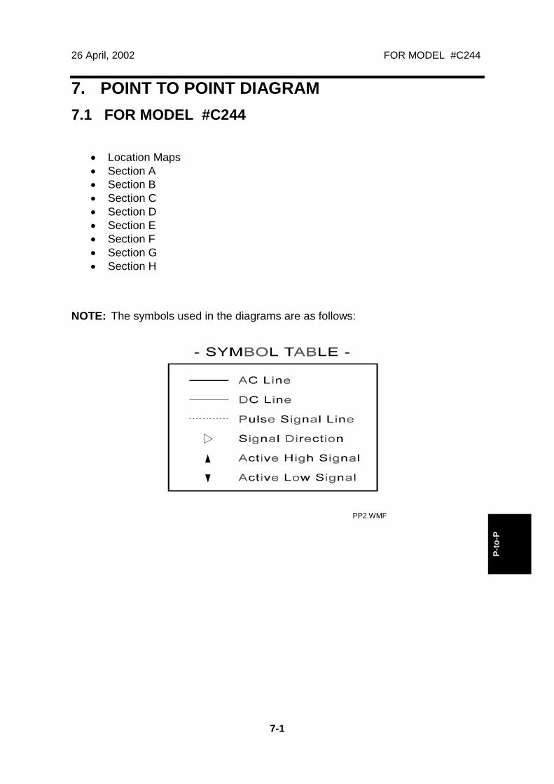
26 April, 2002 FOR MODEL #C244
7-1
P-to
-P
7. POINT TO POINT DIAGRAM7.1 FOR MODEL #C244
• Location Maps• Section A• Section B• Section C• Section D• Section E• Section F• Section G• Section H
NOTE: The symbols used in the diagrams are as follows:
PP2.WMF
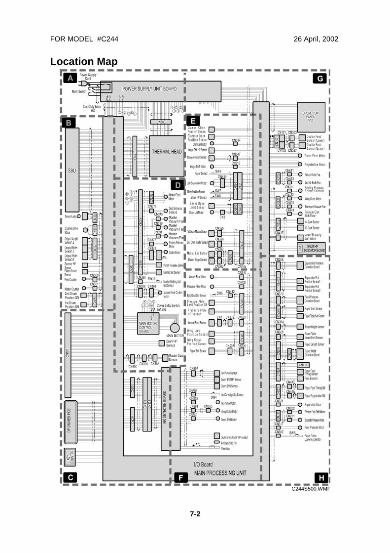
FOR MODEL #C244 26 April, 2002
7-2
Location Map
C244S500.WMF
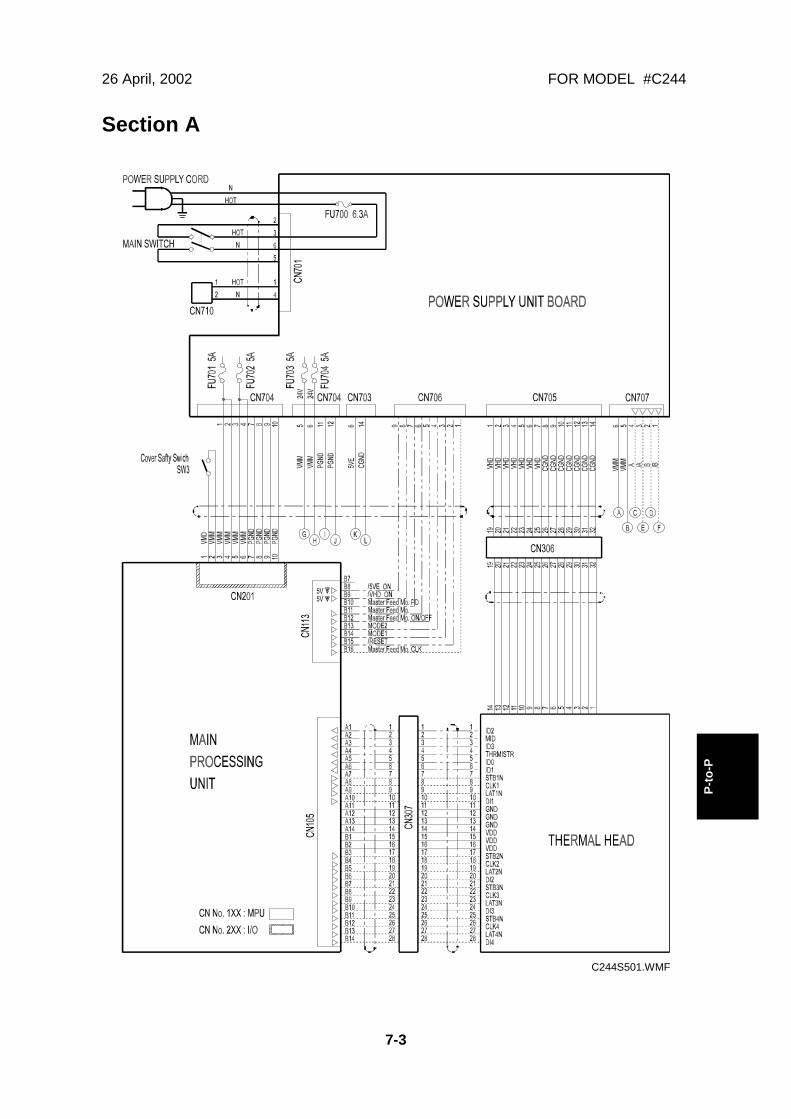
26 April, 2002 FOR MODEL #C244
7-3
P-to
-P
Section A
C244S501.WMF
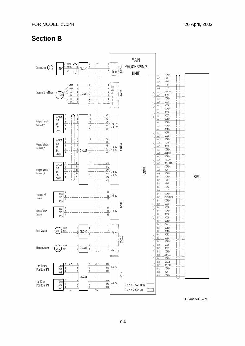
FOR MODEL #C244 26 April, 2002
7-4
Section B
C244S502.WMF
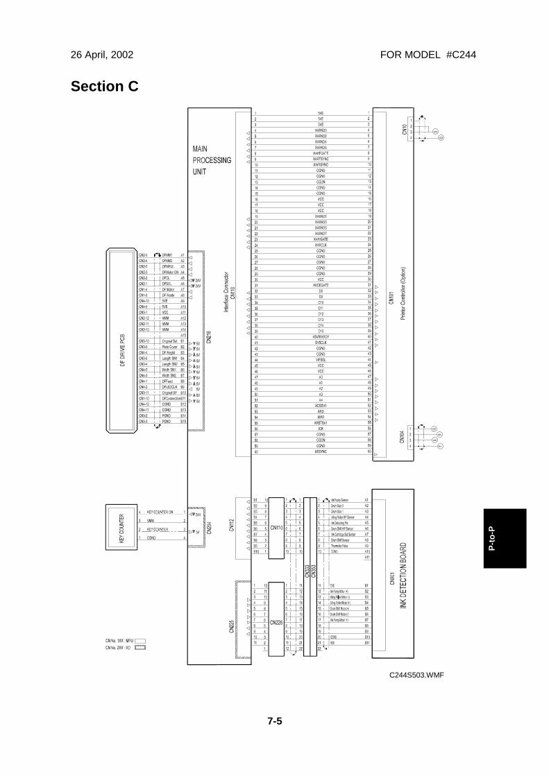
26 April, 2002 FOR MODEL #C244
7-5
P-to
-P
Section C
C244S503.WMF

FOR MODEL #C244 26 April, 2002
7-6
Section D
C244S504.WMF

26 April, 2002 FOR MODEL #C244
7-7
P-to
-P
Section E
C244S505.WMF
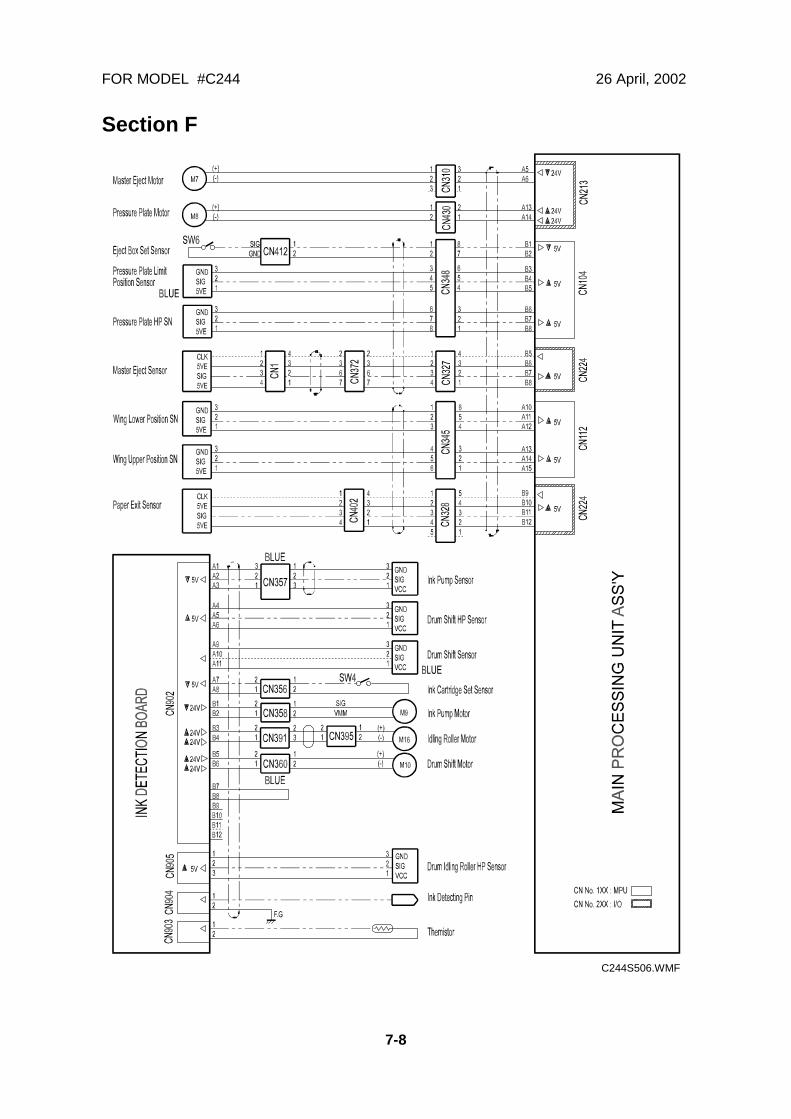
FOR MODEL #C244 26 April, 2002
7-8
Section F
C244S506.WMF
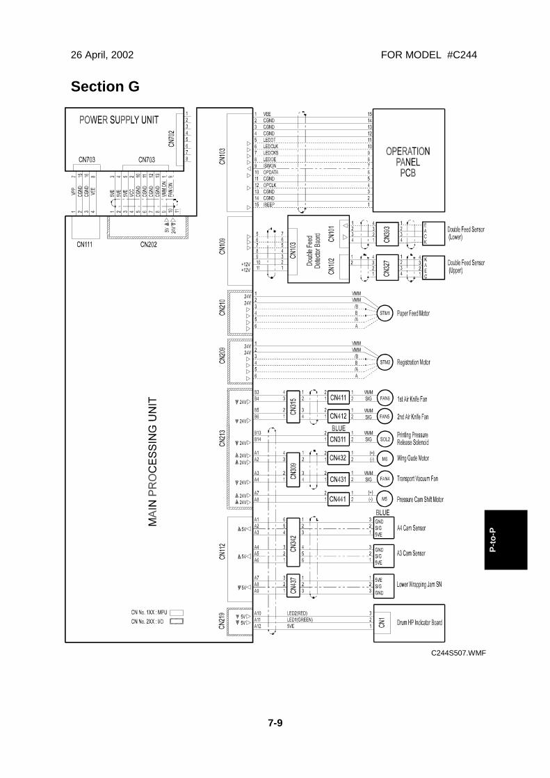
26 April, 2002 FOR MODEL #C244
7-9
P-to
-P
Section G
C244S507.WMF
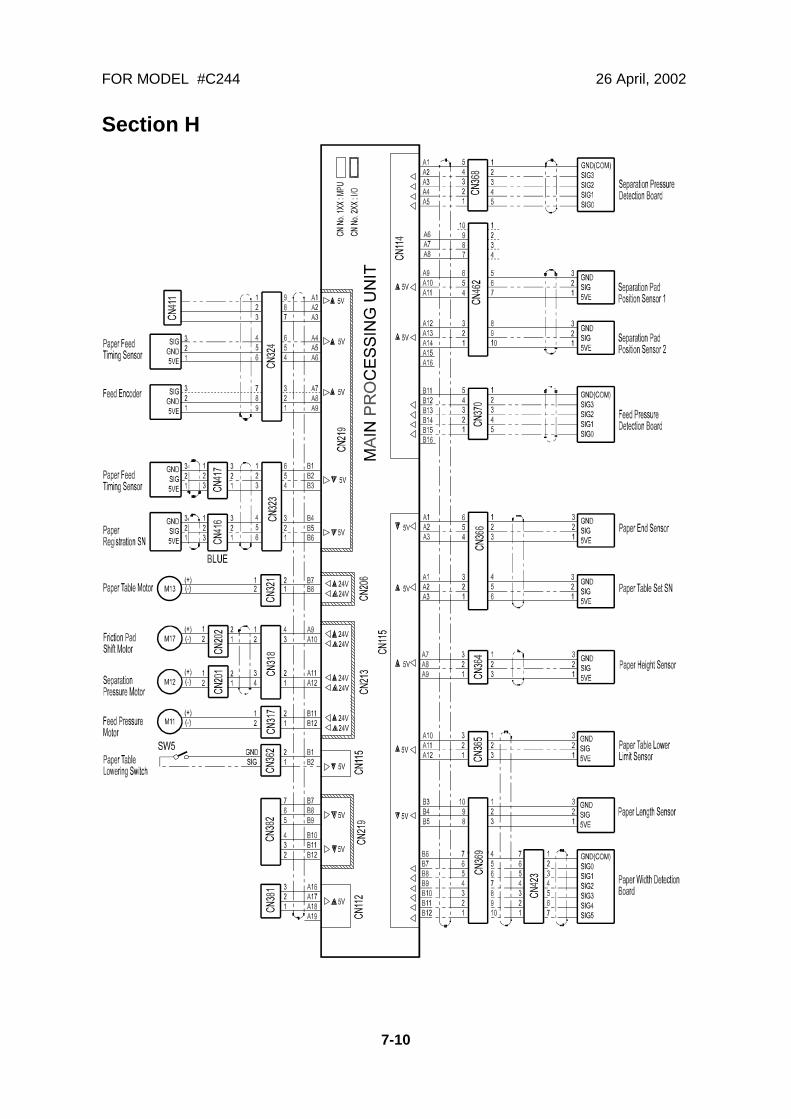
FOR MODEL #C244 26 April, 2002
7-10
Section H
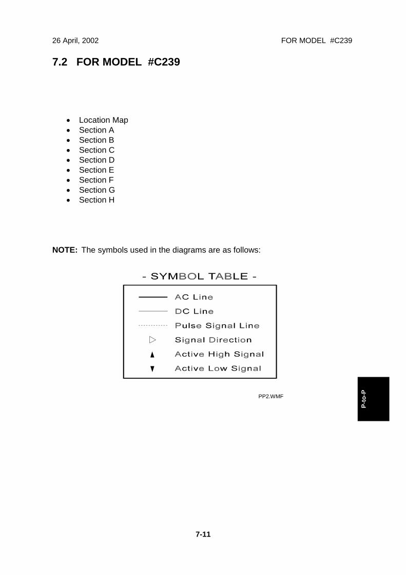
26 April, 2002 FOR MODEL #C239
7-11
P-to
-P
7.2 FOR MODEL #C239
• Location Map• Section A• Section B• Section C• Section D• Section E• Section F• Section G• Section H
NOTE: The symbols used in the diagrams are as follows:
PP2.WMF
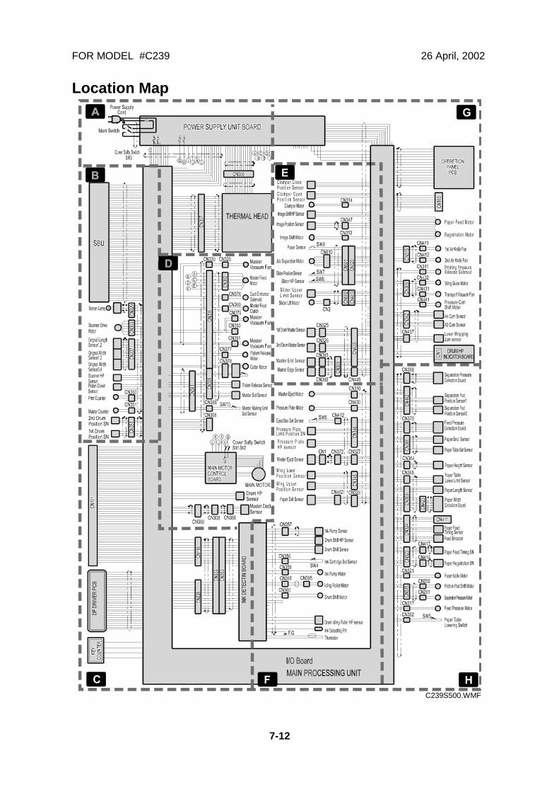
FOR MODEL #C239 26 April, 2002
7-12
Location Map
C239S500.WMF

26 April, 2002 FOR MODEL #C239
7-13
P-to
-P
Section A
C239S501.WMF
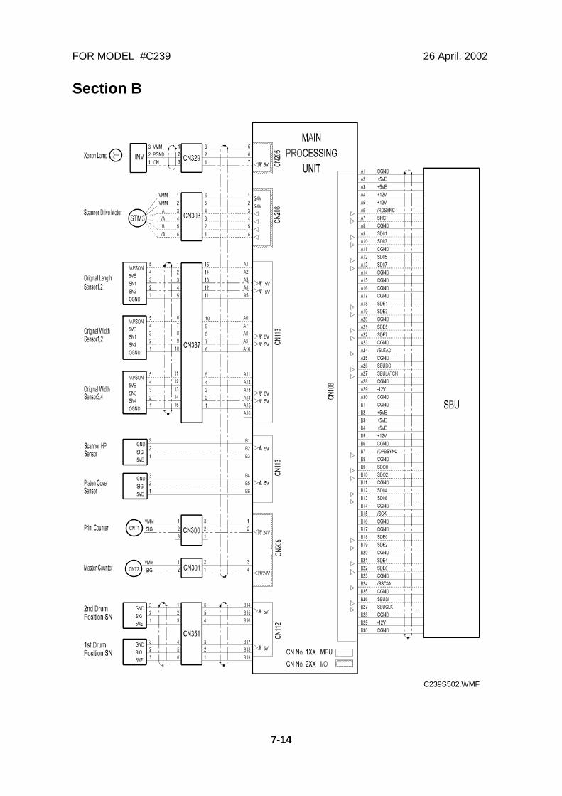
FOR MODEL #C239 26 April, 2002
7-14
Section B
C239S502.WMF

26 April, 2002 FOR MODEL #C239
7-15
P-to
-P
Section C
C239S503.WMF
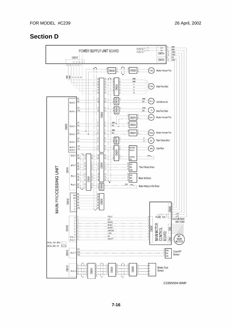
FOR MODEL #C239 26 April, 2002
7-16
Section D
C239S504.WMF
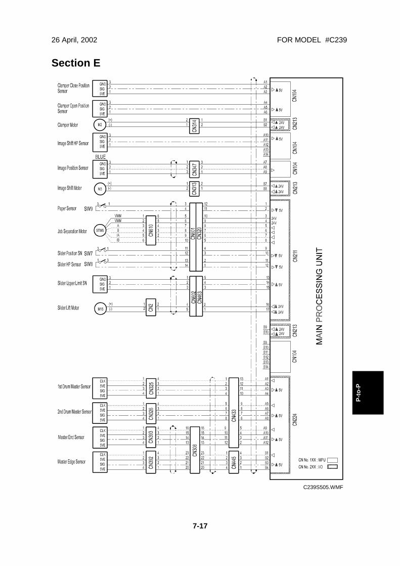
26 April, 2002 FOR MODEL #C239
7-17
P-to
-P
Section E
C239S505.WMF

FOR MODEL #C239 26 April, 2002
7-18
Section F
C239S506.WMF
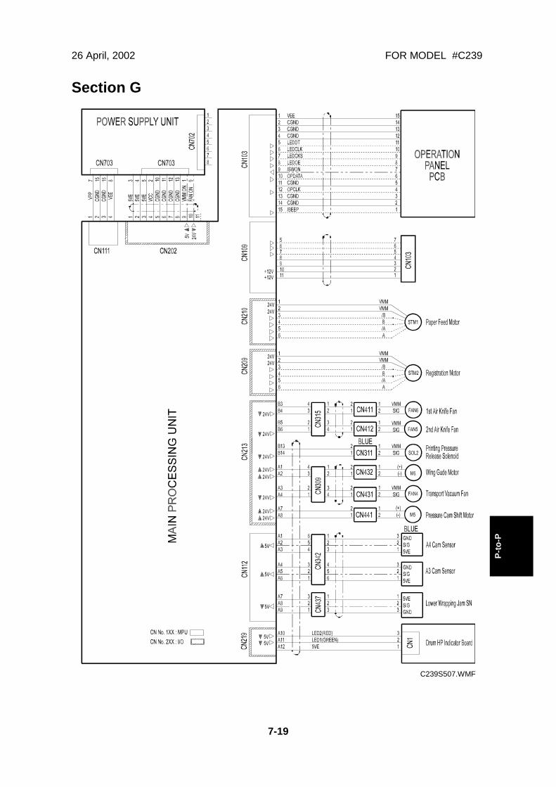
26 April, 2002 FOR MODEL #C239
7-19
P-to
-P
Section G
C239S507.WMF
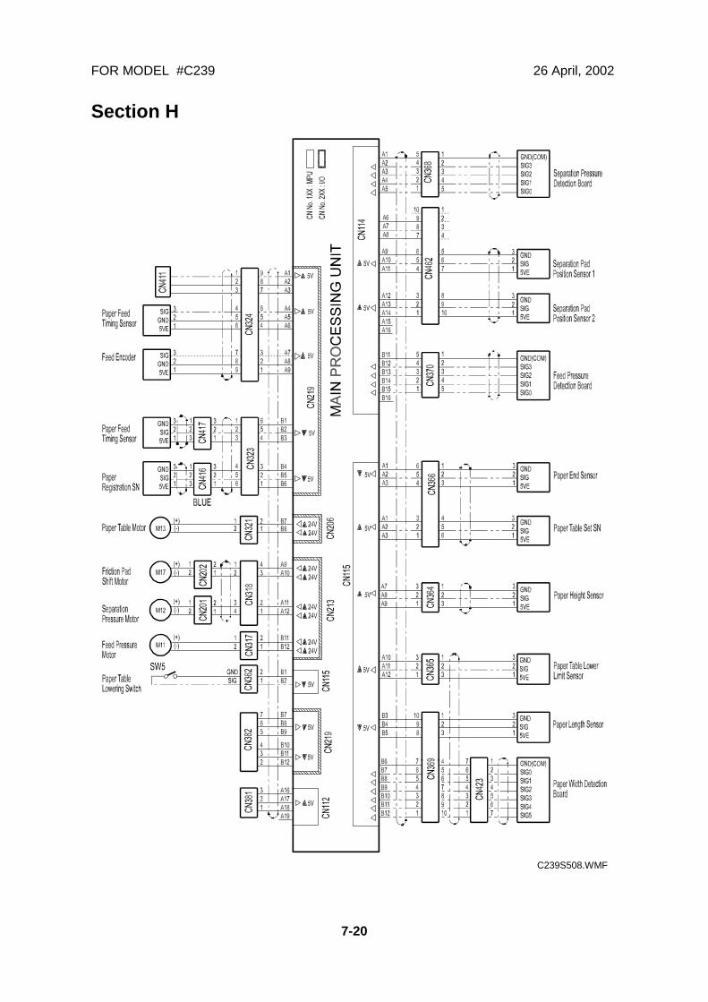
FOR MODEL #C239 26 April, 2002
7-20
Section H
C239S508.WMF