Instruction and maintenance manual - Machine Mart
15
Instruction and maintenance manual 197634000 - ED.6 - 08/2010 - ENGLISH CONCEPT / CONCEPT SE Index Declaration of conformity ............................................................................ 2 Foreword .................................................................................................... 3 1.General information ................................................................................. 4 2.Installation ............................................................................................... 6 3.Start-up .................................................................................................... 7 4.Maintenance ............................................................................................ 9 5.Troubleshooting ....................................................................................... 11 6.Wiring diagrams....................................................................................... 11 7.Technical data.......................................................................................... 15 CE
-
Upload
khangminh22 -
Category
Documents
-
view
0 -
download
0
Transcript of Instruction and maintenance manual - Machine Mart
Instruction and maintenance manual
197634000 - ed.6 - 08/2010 - english
ConCept / ConCept se
indexDeclaration of conformity ............................................................................ 2Foreword .................................................................................................... 31.General information ................................................................................. 42.Installation ............................................................................................... 63.Start-up .................................................................................................... 74.Maintenance ............................................................................................ 95.Troubleshooting ....................................................................................... 116.Wiring diagrams ....................................................................................... 117.Technical data .......................................................................................... 15
CE

deClARAtion oF ConFoRMitY
The following declaration is attached to the compressor in original copy.All identification data: manufacturer, model, code and serial number are stamped on EC label.
I - Dichiara sotto la sua esclusiva responsabilità, che ilcompressore d'aria qui di seguito descritto è conforme alleprescrizioni di sicurezza delle direttive: 2006/42/CE,2000/14/CE, 2006/95/CE, 2004/108/CE, 2009/105/CE, EN1012-1, EN 60204-1, EN 60335-1, EN 61000-6-3/4.
GR : 2006/42/EE, 2000/14/EE, 2006/95/EE, 2004/108/EE,2009/105/CE, EN 1012-1, EN 60204-1, EN 60335-1, EN61000-6-3/4.
GB - Declares under its sole responsibility that the aircompressor described below complies with the safetyrequirements of directives: 2006/42/EC, 2000/14/EC,2006/95/EC, 2004/108/EC, 2009/105/EC, EN 1012-1, EN60204-1, EN 60335-1, EN 61000-6-3/4
PL - Oświadcza pod pełną własną odpowiedzialność, Ŝeopisana niŜej spręŜarka powietrzna odpowiada wymaganiombezpieczeństwa zawartym w Dyrektywach 2006/42/EC,2000/14/EC, 2006/95/EC, 2004/108/EC, 2009/105/EC, EN1012-1, EN 60204-1, EN 60335-1, EN 61000-6-3/4
F - Déclare sous son entière responsabilité que lecompresseur d’air décrit ci-après est conforme auxprescriptions de sécurité des directives : 2006/42/CE,2000/14/CE, 2006/95/CE, 2004/108/CE, 2009/105/CEE, EN1012-1, EN 60204-1, EN 60335-1, EN 61000-6-3/4..
CZ - prohlašuje s plnou odpovědností, že uvedený vzduchovýkompresor vyhovuje bezpečnostním požadavkům směrnic2006/42/ES, 2000/14/ES, 2006/95/ЕS, 2004/108/ЕS ,2009/105/ES, EN 1012-1, EN 60204-1, EN 60335-1, EN61000-6-3/4.
D - Erklärt unter ihrer alleinigen Verantwortung, daß der in Folgebeschriebene Luftkompressor den Sicherheitsvorschriften derRichtlinien: 2006/42/EG, 2000/14/EG, 2006/95/EG, 2004/108/EG,2009/105/EG, EN 1012-1, EN 60204-1, EN 60335-1, EN 61000-6-3/4..
SK - Zodpovedne vyhlásuje, že uvedený vzduchový kompresorzodpovedá bezpečnostným požiadavkám smerníc 2006/42/ES,2000/14/ES, 2006/95/ES, 2004/108/ES, 2009/105/ES, EN1012-1, EN 60204-1, EN 60335-1, EN 61000-6-3/4.
E - Declara bajo su exclusiva responsabilidad que elcompresor de aire descrito a continuación responde a lasprescripciones de seguridad de las directivas : 2006/42/CE,2000/14/CE, 2006/95/CE, 2004/108/CE, 2009/105/CEE, EN1012-1, EN 60204-1, EN 60335-1, EN 61000-6-3/4
H - Teljes felelısségének tudatában tanúsítja, hogy azalábbiakban jellemzett légkompresszor a 2006/42/EC,2000/14/EC, 2006/95/ЕС, 2004/108/ЕС, 2009/105/EC, EN1012-1, EN 60204-1, EN 60335-1, EN 61000-6-3/4
NL - Verklaart onder zijn eigen verantwoordelijkheid dat dehieronder beschreven luchtcompressor in overeenstemming ismet de veiligheidsvoorschriften van de richtlijnen: 2006/42/EG,2000/14/EG, 2006/95/EG, 2004/108/EG, 2009/105/EG, EN1012-1, EN 60204-1, EN 60335-1, EN 61000-6-3/4
LT - Su visa atsakomybe pareiškia, kad žemiau aprašytas orokompresorius atitinka saugumo direktyvų 2006/42/ES,2000/14/ES, 2006/95/ES, 2004/108/ES, 2009/105/ES, EN1012-1, EN 60204-1, EN 60335-1, EN 61000-6-3/4
N - Erklærer under eget ansvar at luftkompressoren her beskreveter i overensstemmelse med sikkerhetsforskriftene i direktivene:,2006/42/EC, 2000/14/EC, 2006/95/EC, 2004/108/EC, 2009/105/EC,EN 1012-1, EN 60204-1, EN 60335-1, EN 61000-6-3/4..
LV - Apliecinā zem savas pilnīgas atbildības, ka apakšāaprakstītais gaisa kompresors atbilst direktīvu 2006/42/EC,2000/14/EC, 2006/95/ЕС, 2004/108/ЕС, 2009/105/EC, EN1012-1, EN 60204-1, EN 60335-1, EN 61000-6-3/4..
S - Försäkrar under eget ansvar att den luftkompressor sombeskrivs följande är i överensstämmelse medsäkerhetsföreskrifterna i EU-direktiv: 2006/42/EG, 2000/14/EG,2006/95/EG, 2004/108/EG, 2009/105/EG, EN 1012-1, EN60204-1, EN 60335-1, EN 61000-6-3/4..
EST - Avaldab enda täieliku vastatusega, et edaspidikirjeldatud õhukompressor vastav ohutuse nõudmisteledirektiividele 2006/42/CE, 2000/14/CE, 2006/95/CE,2004/108/CE, 2009/105/CE, EN 1012-1, EN 60204-1, EN60335-1, EN 61000-6-3/4.
DK - Forsikrer på eget ansvar, at luftkompressoren, derbeskrives nedenfor, er i overensstemmelse medsikkerhedsforskrifterne i direktiverne: 2006/42/EC, 2000/14/EC,2006/95/EC, 2004/108/EC, 2009/105/EC, EN 1012-1, EN60204-1, EN 60335-1, EN 61000-6-3/4..
SLO - Na lastno odgovornost izjavlja, da je spodaj opisanizračni kompresor v skladu z varnostnimi predpisi, ki veljajo zastroje 2006/42/EU, 2000/14/EU, 2006/95/EU, 2004/108/EU ,2009/105/EU, EN 1012-1, EN 60204-1, EN 60335-1, EN61000-6-3/4..
P - Declara sob a sua exclusiva responsabilidade que ocompressor de ar descrito a seguir está em conformidade comas prescrições de segurança das directivas: 2006/42/CE,2000/14/CE, 2006/95/CE, 2004/108/CE, 2009/105/CEE, EN1012-1, EN 60204-1, EN 60335-1, EN 61000-6-3/4
RO – Declara pe propria raspundere ca,compresorul de aerdenumit in continuare,este in conformitate cu cerintele desecuritate cuprinse in directivele:2006/42/CE, 2000/14/CE,2006/95/CE, 2004/108/CE , 2009/105/CE, EN 1012-1, EN60204-1, EN 60335-1, EN 61000-6-3/4.
FI - Vakuuttaa, että seuraavassa esitelty ilmakompressorivastaa alla lueteltujen direktiivien turvallisuusvaatimuksia:2006/42/EC, 2000/14/EC, 2006/95/EC, 2004/108/EC,2009/105/EC, EN 1012-1, EN 60204-1, EN 60335-1, EN61000-6-3/4..
RU - Заявляет под свою полную ответственность, чтонижеописанный воздушный компрессор соответствуеттребованиям безопасности согласно директивам2006/42/EC, 2000/14/EC, 2006/95/ЕС, 2004/108/ЕС,2009/105/EC, EN 1012-1,EN 60204-1,EN 60335-1,EN 61000-6-3/4
2
Use of the instruction manualThis manual is integral part of this compressor and should be kept for its whole working life.Keep this manual in a safe place so not to damage it.If the compressor is sold to a third party, also give the Instruction Manual to the new Owner.This manual should be carefully read before starting the compressor up and in case of any
doubt on its operation.This manual contains important safety information on operation procedures, which should be
complied with, otherwise injuries to people or damages to the machine might occur. Important use and maintenance instructions are also mentioned in this manual.
Should this manual be lost, please ask for a new copy.Spare parts list is not considered as integral part of this manual, since it is available at autho-
rized dealers’ offices only.
symbolsThe following symbols are used for especially important information:
Caution Highlights precautions to be taken to ensure safety of the operator, people in the com-
pressor working area and the compressor.notesHighlights recommended instructions or precautions to be taken to have an easier
maintenance procedure or to explain most important instructions.specialized personnelEvery intervention highlighted by this symbol is exclusively the job of a specialized
technician.
technical AssistanceUse only genuine spare parts for servicing the compressor.Non-genuine spare parts might cause injuries to people. For efficient Technical Assistance,
please always state model, type and part number of Your compressor. Those data are specified both on compressor plate and label on manual cover page.
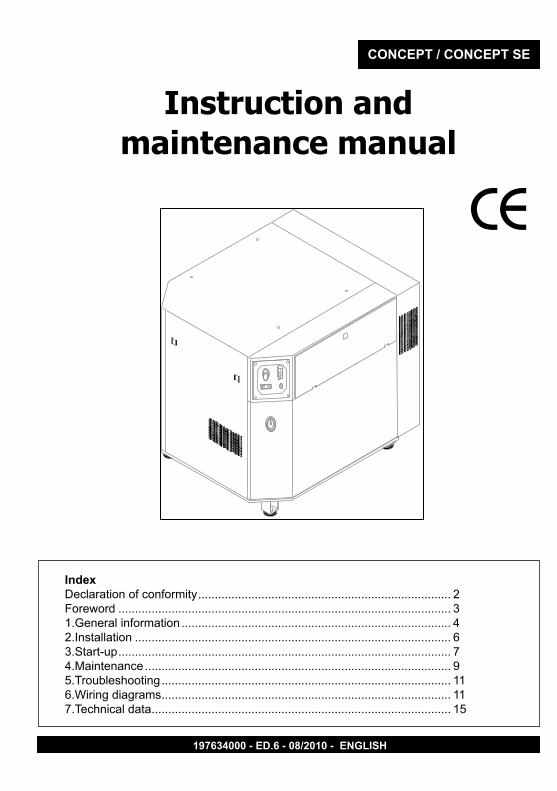
Product identificationFor any request for copies it is ESSENTIAL to provide ALL the data stamped on EC label.
FoReWoRd
Manufacturer’s data
TYPE = name CODE = compressor codeSERIAL NO. = serial number
Air delivered (l/min) and (cfm)
Technical data: voltage (V/ph/Hz)absorption (A) power (HP and kW)rotations per minute (Rpm).
other approvals
CE mark year of manufacturemax. pres-
sure (bar and PSI)
noise level dB(A)
3

1. geneRAl inFoRMAtionThis compressor was designed and manufactured to be used only to deliver compressed
air for handicraft and/or industrial applications in full compliance with the safety instruc-tions provided in the following paragraphs.
Compressor can be equipped with several accessories for blowing, washing and painting as well as air tools. See the relevant manuals for correct use of accessories and tools.
Carefully read the User’s Manual before servicing the compressor. Before performing maintenance work, switch off the compressor and cut off power supply by
switching off the wall-mounted switch (if any).
What shoUld Be done:Understand how to stop the compressor at once and become familiar with the use of all
controls.Before any operation the air in the compressor tank should be released, then close the cock
(if provided) located between the compressor and the tank; unplug the compressor so to avoid any accidental compressor start.
After any maintenance operation make sure all the disassembled parts are properly as-sembled.
To have a safe operation, make all checks mentioned in chapter “Start-up” before starting the compressor.Keep children and animals away from the working area, so as to avoid any injury caused by
devices connected to the compressor.Carefully read the instructions of any tool you have installed, especially if a spray gun is used,
make sure the shop is well ventilated before you start painting.Always start and stop three-phase compressor through the wall switch. Should the compressor be working around the clock, the use of soundproof headset is rec-
ommended.
What shoUld neVeR Be done:Do not paint indoor or close to naked flames.Never touch cylinder head, cooling fins and delivery tube since they become very hot while
working. They are still very hot for some time after stopping the compressor.Never place inflammable nylon or cloth objects near or/and on the compressor.Never move the compressor when the tank is under pressure.Never use the compressor if the power cable is faulty or the connection is not safe.Never aim the air jet either at people or animals.Never allow anyone to operate the compressor without giving him/her proper instructionsNever hit flywheel and fans with metal or blunt objects. Compressor might break or be seri-
ously damaged.Never operate the compressor without an air filter.Never tamper with the safety valve or the tank.Never use the compressor in potentially explosive premises.Never connect the air outlet cock to a tube with a max. capacity which is lower than the com-
pressor capacity.Never run the compressor when temperature is under 0°C .
4
1.geneRAl inFoRMAtionstandard accessories
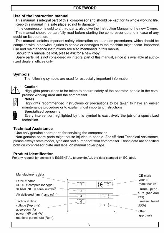
Your compressor is delivered with the following accessories (fig.1):• User’s manual (cd-rom)• Vibration-dampers + key to open panels • Elbow + line cock • Connection hose (models without tank).
Unpacking and handlingThe compressor is usually shipped to the customer with a carton
cover. Wear protective gloves and cut outer straps. Remove then package by lifting it from the top.
Before removing the compressor, make sure it is intact (outside), open access doors (if any) and visually check components for dam-age. Check that all accessories are included.
Lift machine with a transpallet or fork lift truck, fit the vibration-damp-ing pads in their housings and transport the machine with the utmost care to the place of installation. (fig.2)
Connect the elbow as shown, and then connect the connection hose and the line cock supplied (fig.2). Connection to tank and/or to a compressed air line must be carried out by a specialised technician.
You are advised to keep the packing material in the event you need to re-locate the compressor. Keep package at least for the duration of the warranty period, so the compressor can be safely shipped to a service centre, if needed.
When no longer needed, deliver packing material to the special collection centres for disposal.
Compressor descriptionCompressor main components are (fig.3):
1. Bare pump 2. Air radiator 3. Oil control (if any)4. Check valve5. Electric motor 6. Pressure switch(positioned outside on
SE models)7. Control panel(apart from SE models)
8.Electric equipment (apart from SE models)
2
1
5
2
4
6
78
3
1
3
5
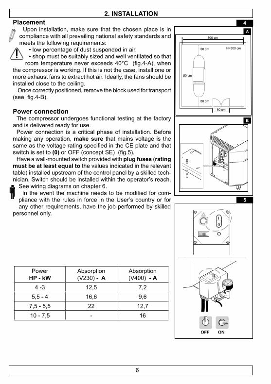
placementUpon installation, make sure that the chosen place is in
compliance with all prevailing national safety standards and meets the following requirements:
• low percentage of dust suspended in air, • shop must be suitably sized and well ventilated so that
room temperature never exceeds 40°C (fig.4-A), when the compressor is working. If this is not the case, install one or more exhaust fans to extract hot air. Ideally, the fans should be installed close to the ceiling.
Once correctly positioned, remove the block used for transport (see fig.4-B).
power connectionThe compressor undergoes functional testing at the factory
and is delivered ready for use. Power connection is a critical phase of installation. Before
making any operation, make sure that mains voltage is the same as the voltage rating specified in the CE plate and that switch is set to (0) or OFF (concept SE) (fig.5).
Have a wall-mounted switch provided with plug fuses (rating must be at least equal to the values indicated in the relevant table) installed upstream of the control panel by a skilled tech-nician. Switch should be installed within the operator’s reach.
See wiring diagrams on chapter 6. In the event the machine needs to be modified for com-
pliance with the rules in force in the User’s country or for any other requirements, have the job performed by skilled
personnel only.
2. instAllAtion
Power hp - kW
Absorption (V230) - A
Absorption (V400) - A
4 -3 12,5 7,25,5 - 4 16,6 9,6
7,5 - 5,5 22 12,710 - 7,5 - 16
5
4A
B
6
type of operationstarting
Concept se: compressor start is controlled by a pressure switch (switch on ON - fig.5), and after a few seconds the compressor reaches correct rpm.Concept Ct (star-delta): by pressing the “I” button located on the dashboard (Figure 5),
the boot sequence starts. The compressor starts slowly (“star” connection), then after about 7 seconds enters the “delta” connection and the normal operating cycle starts.
operationThe compressor will stop when max. pressure is reached and it will automatically restart only
when pressure is at the minimum allowed value. The default values (unless otherwise requested) are as follows:Standard models (Max 10 bar): 8 bar start / stop 10 barHigh pressure models - AP (max pressure14 bar): start 12 bar / stop 14 bar
Working pressure adjustment At User’s discretion, a pressure reducer can be installed downstream of the compressor. Have the distribution line configured by a qualified technician. Always look up the ideal operating pressure of the tool you wish to use in the relevant manual.
After use, set pressure to 0 in order to prevent early wear of pressure reducer.
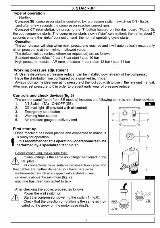
Controls and check devices(fig.6)The control panel (apart from SE models) includes the following controls and check devices 1. 0/1 Switch (TA) - ON/OFF (SE)2. Oil level light (if provided with oil control)3. Emergency stop button 4. Working hour counter5. Air pressure gauge at delivery end
First start-upOnce machine has been placed and connected to mains, it is ready for operation.
it is recommended this operation - operational test - be performed by a specialized technician.
Before continuing, make sure that:mains voltage is the same as voltage mentioned in the
CE plate;all connections have suitable cross-section cable and
that cables are neither damaged nor have bare wires;wall-mounted switch is equipped with suitable fuses;oil level is above the minimum (fig. 7);machine has been connected to tank.
After checking the above, proceed as follows:Power the wall switch on Start the compressor powering the switch 1 (fig.6).Check that the direction of rotation is the same as indi-
cated by the arrow on the motor case (fig.8).
3. stARt-Up
6
0I
1
2
3
4
5
1
5
MAX
MIN
MAX
MIN
7
7

3. stARt-UpIf the compressor is running in the wrong direction of rotation,
power the machine immediately off. Power the main switch off and reverse two phases at terminals L1-L2-L3 of the switch. Restart the machine after powering the voltage on.
Allow the motor to run for at least 5 minutes with the air cock open. Close the air cock and check that compressor is loading tank and that it duly stops once pressure gauge 5 detects that max. pressure has been reached.
Now you may appreciate the easiness of use of your com-pressor. The pressure switch, which stops the motor when the max. pressure allowed is achieved, makes the compressor start again when pressure goes below the minimum threshold (about 2 bar less than the max. pressure).
To stop the compressor, always use switch 1. That way, compressed air is drained from inside the head and re-starting is facilitated.
Press the emergency stop button in emergency cases ONLY.
safety devicesOperating pressure switch (see fig. 3/5): determines STOP and START pres-suresOil level control (if provided )
1) Oil level is checked every 5 seconds during compressor standard operating mode. If the feeler detects a low oil level for 12 times in a row, the compressor is stopped and the warning light (fig. 9- ref. 2) turns on (steady light).
What to do: power off and check the oil level, top up if neces-sary. Allow some minutes and then restart the compressor. Should the machine stop once again, call an authorized service center.
2) If the light (fig. 9-ref.2) flashes after starting up the compressor or during compressor standard operation, the following might have happened:
feeler short-circuited or contact open. Call an authorized service center in any case, as the feeler needs to be replaced.
Should the above happen, the compressor can work for 3 hours more. Then it should be powered off and on again to continue working until the feeler is replaced.
Oil level indicator (fig.9)
ALWAYS CHECK OIL LEVEL BEFORE RESTARTING THE COMPRESSOR.
•
•
•
•
8
9
0I
2
�
Before carrying out any maintenance operation: switch off the machine and the wall-mounted switch.
Bleed air from inside compressor and/or tank.Close the air cock between compressor and tank (if provided )
Cabinet panels disassemblyFront and upper panels have to be removed to access the compressor. Upper panel: unscrew the screws with a 5-mm socket wrench and lift the panel. Front panel: use the key supplied with the machine to open the locks and remove panel by
first pulling it upwards and then outwards. never operate the compressor with the protection panels removed.
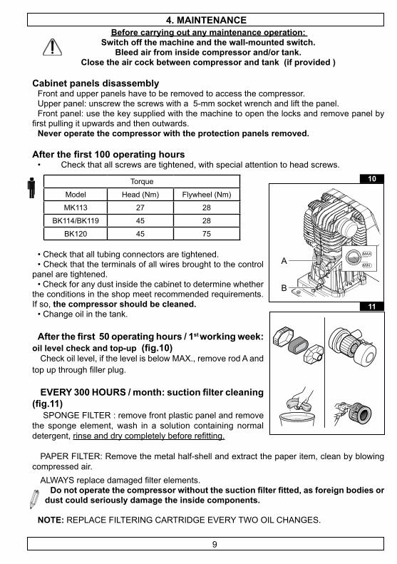
After the first 100 operating hours • Check that all screws are tightened, with special attention to head screws.
• Check that all tubing connectors are tightened. • Check that the terminals of all wires brought to the control
panel are tightened. • Check for any dust inside the cabinet to determine whether
the conditions in the shop meet recommended requirements. If so, the compressor should be cleaned.
• Change oil in the tank.
After the first 50 operating hours / 1st working week: oil level check and top-up (fig.10)
Check oil level, if the level is below MAX., remove rod A and top up through filler plug.
EVERY 300 HOURS / month: suction filter cleaning (fig.11)
SPONGE FILTER : remove front plastic panel and remove the sponge element, wash in a solution containing normal detergent, rinse and dry completely before refitting.
PAPER FILTER: Remove the metal half-shell and extract the paper item, clean by blowing compressed air.
ALWAYS replace damaged filter elements.Do not operate the compressor without the suction filter fitted, as foreign bodies or
dust could seriously damage the inside components.
note: REPLACE FILTERING CARTRIDGE EVERY TWO OIL CHANGES.
4. MAintenAnCe
Torque
Model Head (Nm) Flywheel (Nm)
MK113 27 2�
BK114/BK119 45 2�
BK120 45 75
A
B
10
11
9
4. MAintenAnCe
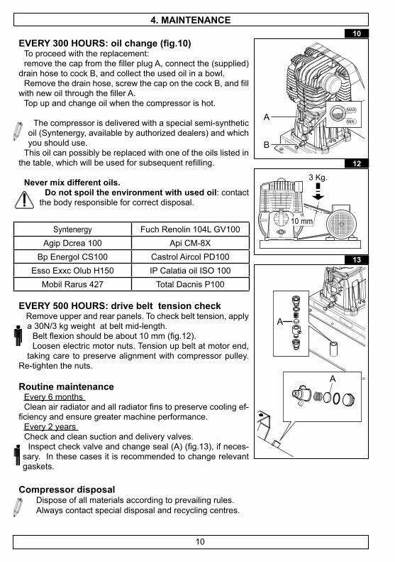
EVERY 300 HOURS: oil change (fig.10) To proceed with the replacement:remove the cap from the filler plug A, connect the (supplied)
drain hose to cock B, and collect the used oil in a bowl.Remove the drain hose, screw the cap on the cock B, and fill
with new oil through the filler A.Top up and change oil when the compressor is hot.
The compressor is delivered with a special semi-synthetic oil (Syntenergy, available by authorized dealers) and which you should use.
This oil can possibly be replaced with one of the oils listed in the table, which will be used for subsequent refilling.
never mix different oils.do not spoil the environment with used oil: contact
the body responsible for correct disposal.
eVeRY 500 hoURs: drive belt tension check Remove upper and rear panels. To check belt tension, apply a 30N/3 kg weight at belt mid-length.
Belt flexion should be about 10 mm (fig.12). Loosen electric motor nuts. Tension up belt at motor end,
taking care to preserve alignment with compressor pulley. Re-tighten the nuts.
Routine maintenanceEvery 6 months Clean air radiator and all radiator fins to preserve cooling ef-
ficiency and ensure greater machine performance. Every 2 years Check and clean suction and delivery valves. Inspect check valve and change seal (A) (fig.13), if neces-
sary. In these cases it is recommended to change relevant gaskets.
Compressor disposal Dispose of all materials according to prevailing rules. Always contact special disposal and recycling centres.
Syntenergy Fuch Renolin 104L GV100Agip Dcrea 100 Api CM-8X
Bp Energol CS100 Castrol Aircol PD100Esso Exxc Olub H150 IP Calatia oil ISO 100
Mobil Rarus 427 Total Dacnis P100
A
B
10
3 Kg.
10 mm
12
A
A
13
10
5. tRoUBleshooting
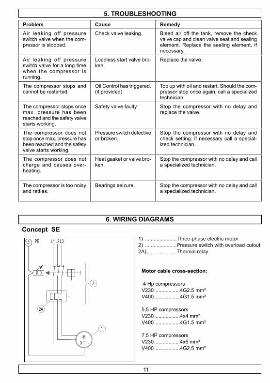
6. WiRing diAgRAMsConcept se
1 2 3
M3
P
LL L
1
2A
2
PE 1) ......................Three-phase electric motor 2) ......................Pressure switch with overload cutout2A) .....................Thermal relay
problem Cause RemedyAir leaking off pressure switch valve when the com-pressor is stopped.
Check valve leaking. Bleed air off the tank, remove the check valve cap and clean valve seat and sealing element. Replace the sealing element, if necessary.
Air leaking off pressure switch valve for a long time when the compressor is running.
Loadless start valve bro-ken.
Replace the valve.
The compressor stops and cannot be restarted.
Oil Control has triggered. (if provided)
Top up with oil and restart. Should the com-pressor stop once again, call a specialized technician.
The compressor stops once max. pressure has been reached and the safety valve starts working.
Safety valve faulty Stop the compressor with no delay and replace the valve.
The compressor does not stop once max. pressure has been reached and the safety valve starts working.
Pressure switch defective or broken.
Stop the compressor with no delay and check setting: if necessary call a special-ized technician.
The compressor does not charge and causes over-heating.
Heat gasket or valve bro-ken.
Stop the compressor with no delay and call a specialized technician.
The compressor is too noisy and rattles.
Bearings seizure. Stop the compressor with no delay and call a specialized technician.
Motor cable cross-section:
4 Hp compressorsV230 ..................4G2.5 mm²V400 ..................4G1.5 mm²
5,5 HP compressorsV230 ..................4x4 mm²V400 ..................4G1.5 mm²
7,5 HP compressorsV230 ..................4x6 mm²V400 ..................4G2.5 mm²
11
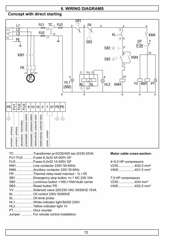
6. WiRing diAgRAMsConcept with direct starting
TC .....................Transformer pr.0/230/400 sec.0/230 63VA FU1-FU2 ...........Fuses 6,3x32 4A 500V GFFU3 ...................Fuses 6,3x32 1A 500V GFKM1 ...................Line contactor 230V 50-60HzKM4 ...................Ancillary contactor 230V 50-60HzFR .....................Thermal relay-reset man/aut - 1L+1RSB1 ...................Emergency stop button +n.1 NC 230 10ASB2 ...................Luminous button +1NC+1NA+bulb carrierSB3 ...................Reset button FRYV .....................Solenoid valve 220/230 VAC 50/60HZ 15VAKL ......................Oil control 230V 50/60HZSL ......................Oil level probeHL1 ....................White indicator light BASS 230VHL2 ....................Yellow indicator light 10PT ..................... Hour counterJumper ............ For remote control installation
Motor cable cross-section:
4÷5,5 HP compressorsV230 ..................4G2.5 mm²V400 ..................4G1.5 mm²
7,5 HP compressorsV230 ..................4G4 mm²V400 ..................4G2.5 mm²
h
P
12

Concept remote start controlled (with oil Control)6. WiRing diAgRAMs
TC .....................Transformer pr.0/230/400 sec.0/230 63VA FU1-FU2 ...........Fuses 6,3x32 4A 500V GFFU3 ...................Fuses 6,3x32 1A 500V GFKM1 ...................Line contactor 230V 50-60HzKM2 ...................Delta contactor 230V 50-60HzKM3 ...................Star contactor 230V 50-60Hz KM4 ...................Ancillary contactor 230V 50-60HzKT ......................Timer 230V 50/60HzFR .....................Thermal relay-reset man/aut - 1L+1RSB1 ...................Emergency stop button +n.1 NC 230 10ASB2 ...................Luminous button +1NC+1NA+bulb carrierSB3 ...................Reset button FRYV .....................solenoid valve 220/230 VAC 50/60HZ 15VAKL ......................Oil control 230V 50/60HZSL ......................Oil level probeHL1 ....................White indicator light BASS 230VHL2 ....................Yellow indicator light 10PT ..................... Hour counterJumper ............ For remote control installation
Motor cable cross-section:
4÷5,5 HP compressorsV230 ..................7G1.5 mm²V400 ..................7G1.5 mm²
7,5÷10 HP compressorsV230 ..................7G2.5 mm²V400 ..................7G1.5 mm²
13
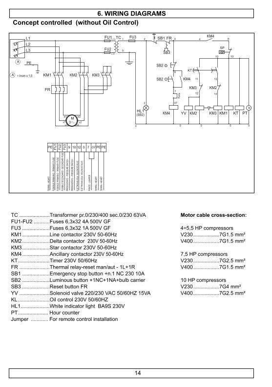
Concept controlled (without oil Control)6. WiRing diAgRAMs
TC .....................Transformer pr.0/230/400 sec.0/230 63VA FU1-FU2 ...........Fuses 6,3x32 4A 500V GFFU3 ...................Fuses 6,3x32 1A 500V GFKM1 ...................Line contactor 230V 50-60HzKM2 ...................Delta contactor 230V 50-60HzKM3 ...................Star contactor 230V 50-60Hz KM4 ...................Ancillary contactor 230V 50-60HzKT ......................Timer 230V 50/60HzFR .....................Thermal relay-reset man/aut - 1L+1RSB1 ...................Emergency stop button +n.1 NC 230 10ASB2 ...................Luminous button +1NC+1NA+bulb carrierSB3 ...................Reset button FRYV .....................Solenoid valve 220/230 VAC 50/60HZ 15VAKL ......................Oil control 230V 50/60HZHL1 ....................White indicator light BA9S 230VPT ..................... Hour counterJumper ............ For remote control installation
Motor cable cross-section:
4÷5,5 HP compressorsV230 ..................7G1.5 mm²V400 ..................7G1.5 mm²
7,5 HP compressorsV230 ..................7G2.5 mm²V400 ..................7G1.5 mm²
10 HP compressorsV230 ..................7G4 mm²V400 ..................7G2.5 mm²
FR
L1L2
PE
TCFU1
KM1A = Inom x 1,5
L3
FU31
0
HL1(SB2)
FU2
A
KM2 KM3
L11
L31
v1u1
w1
3M
v2u2
w2
2 4 4
0
FR KM4
KM4
SB2
SB2
07
SB3
SB1
6
7
KM2YV
2
0 0
hKM1
10
SP
9
PTKT
KM4
0
KM3
KM2KM3
KT
10
1311
12 14
0
P
0
Pont
e
1
FU1
9 10 12
FUSI
BILE
PRI
MARI
O - P
RIMA
RY F
USE
ELET
TROV
ALVO
LA - S
OLEN
OID
VALV
E
TERR
A - H
EART
077
PONT
E - J
UMPE
R
0PE PE
FUSI
BILE
SEC
ONDA
RIO
- SEC
ONDA
RY F
USE
PEFU2
FU3
TERR
A - H
EART
TERR
A - H
EART
ELET
TROV
ALVO
LA - S
OLEN
OID
VALV
E
PRES
SOST
ATO
- PRE
SSUR
E SW
ITCH
PRES
SOST
ATO
- PRE
SSUR
E SW
ITCH
FUSI
BILE
PRI
MARI
O - P
RIMA
RY F
USE
14

7 . teChniCAl dAtA
Concept se MK113 -4 BK114-4 BK114-5,5 BK119-5,5 BK119-7,5 BK119-10
HP / Kw 4 / 3 4 /3 5,5 / 4 5,5 /4 7,5 / 5,5 10 / 7,5V/Hz/ph 400/50/3 400/50/3 400/50/3 400/50/3 400/50/3 400/50/3Amps 7,2 7,2 9,6 9,6 12,7 16
bar 10 10 10 10 10 10Air intake
(l/min)465 480 580 625 840 960
Tank (l) 270 270 270 270 270500
270500
dB(A) 69 70 71 69 70 72Dimemsions
(cm)112x60x137 112x60x137 112x60x137 112x60x137 112x60x137
200x60x137112x60x137200x60x137
Weight (Kg) 173 190 193 196 203 250
210260
Concept tA BK119-5,5 BK119-7,5 BK119-7,5 AP BK120-10 BK120-10 Ap
HP / Kw 5,5 /4 7,5 / 5,5 7,5 / 5,5 10 / 7,5 10 / 7,5V/Hz/ph 400/50/3 400/50/3 400/50/3 400/50/3 400/50/3Amps 9,6 12,7 12,7 16 16
bar 10 10 14 10 14Air intake (l/min) 625 840 705 1080 900
Tank (l) 0270500
0270500
0 270
-
0 -
500
0270
-dB(A) 69 67 70 73 69
Dimemsions (cm) 79x58x70112x60x137200x60x137
79x58x70112x60x137200x60x137
79x58x70112x60x137
91x79x�1-
200x80x150
91x79x�1120x80x150
-Weight (Kg) 108,5
203261
111,5206263
111,5206
165-
305
165250
-
15