instruction manual for air plasma cutting machine model
13
INSTRUCTION MANUAL FOR AIR PLASMA CUTTING MACHINE MODEL –WAP 50 WARPP ENGINEERS PVT.LTD. B‐1005, Western Edge II, Near Metro Mall, Off. Western Express Highway, Borivali (E), Mumbai‐400 066. Tel: 91‐22‐28542272/ 73/74. Fax: 91‐22‐28542275. E‐mail: [email protected] Web Site: www.warpp.co.in
-
Upload
khangminh22 -
Category
Documents
-
view
0 -
download
0
Transcript of instruction manual for air plasma cutting machine model

INSTRUCTION MANUAL FOR AIR PLASMA CUTTING MACHINE
MODEL –WAP 50
WARPP ENGINEERS PVT.LTD. B‐1005, Western Edge II, Near Metro Mall, Off. Western Express Highway,
Borivali (E), Mumbai‐400 066. Tel: 91‐22‐28542272/ 73/74. Fax: 91‐22‐28542275.
E‐mail: [email protected] Web Site: www.warpp.co.in
TABLE OF CONTENTS
1 THE PROCESS 1
2 SAFETY PRECAUTIONS 1
3 EQUIPMENT DESCRIPTION 1
4 FRONT PANEL CONTROL 2
5 THE TORCH 2
6 THE CONSUMABLE 3
7 PRE INSTALLATION REQUIRMENTS 3
8 PRE STARTING CHECKLIST 4
9 CUTTING PROCEDURE 4
10 MAINTENANCE 5
11 FAULT FINDING 6
12 SPARE PART LIST 7
ILLUSTRATIONS
1) TORCH ASSEMBLY (A-151) 8
2) INSTALLATION DIAGRAM 9
3) PLASMA CONTROL WIRING DIAGRAM 10
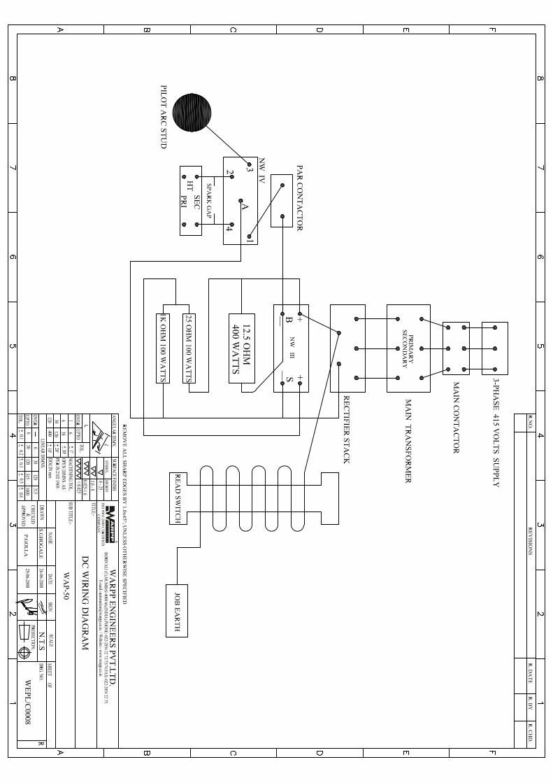
4) D.C.WIRING DIAGRAM 11
5) POWER CIRCUIT WIRING DIAGRAM 12

1. THE PROCESS: Plasma is the fourth state of matter, others being the solid, liquid and gaseous. When a gas is heated to high temperature it changes from molecular state to ionic state. Plasma is electrically conductive as it contains charged particles.
2. SAFETY PRECAUTIONS:
• The mains connection must be properly grounded and the supply lines be fitted with fuses of • Specified ratings. The mains cable must be properly secured to prevent possible damage. • High voltage exists on the torch when power is applied and the pilot arc is struck and when
the main arc is cutting. • The nozzle should not be touched when the power is applied to the torch. • All Adjustments and replacements of the parts should be undertaken with the unit switched
off. • The torch should not be used in excessively wet conditions. • Power supply to the unit should be switched off before removing any panel of the machine
Keep the work area clear from all inflammable materials. Ensure that any material or spark ejected from the cut is not a source of danger to the operator or others.
• Protection is necessary from the ultraviolet radiation emitted by the arc. A helmet with shade glass and gloves should be used while cutting. Adequate screening should be provided to protect others working in the vicinity from ultraviolet radiation.
3. EQUIPMENT DESCRIPTIONS:
The unit consists of following.
• Power Transformer. The power transformer used in this unit is a constant current type transformer with drooping characteristics. The transformer is made of copper coils and F class insulation is used for safety and trouble free performance for a long time. Interlayer air gap is provided in the coils for sufficient cooling.
• Rectifier. Three phase full wave silicon rectifier stack is used to convert the AC output of the transformer to DC. Heat sink of proper rating is employed to see that the diodes doesn’t heat up and cause damage to the rectifier.
• Central Processing Unit (CPU). This unit is an electronic PCB which is the brain of the system. This unit controls the sequence of operation and also detects any malfunctioning in the system. In the event of this occurring this will automatically shut down the machine to prevent any damage to the torch or operator.
1

• Arc Starting System.
When the switch on the torch is initiated an arc is created between the electrode and the nozzle in the torch. This arc which ejects out of the nozzle is called pilot arc. When this pilot arc comes in to contact with the job, main arc is created and the cutting starts.
4. FRONT PANEL CONTROLS.
ON-OFF-TEST three way selector switches. MAIN ON/OFF Switch High/Low Selector Switch Mains Power indicator, Panel Fuse. Air Failure indicator / water failure indicator. Thermal overload indicator. Air Pressure gauge. Air Line to the torch with power manifold. Pilot arc connection to the torch. Remote control socket (Torch Trigger). Job Power Return Cable (Job Earth).
5. THE TORCH:- The torch is a precision tool precisely molded with internal parts perfectly aligned. Although the
torch has been designed to withstand normal workshop abuse care should be taken to ensure that the torch is not excessively knocked about and is maintained properly.
• Basically there are two types of torches:- A. Hand Torch B. Machine Torch • Hand cutting torch has three connections:-
a) Air line with main power manifold. b) Pilot Arc Connection. c) Remote (Torch Trigger)
• Machine torch has only the first two connections and a separate ON-OFF remote pendent is required.
2

6. CONSUMABLES. The torch carries a number of elements known as spares and consumables which are either
eroded or consumed while cutting (Ref to Torch assembly Diagram) While replacing the consumables procedure should be followed and care must be taken to see that cleanliness is of utmost importance. CAUTION: THE EQUIPMENT MUST BE SWITCHED OFF BEFORE REPLACING THE CONSUMABLES.
Unscrew the Nozzle retaining cap
Unscrew the nozzle (Thread less)
Remove the Insulating Spacer
Check the condition of the electrode if it is to be removed then remove it (Thread less) and Fit a New One.
CAUTION: STOP CUTTING IMMEDIATELY IF GREENISH ARC IS OBSERVED WHILE CUTTING OR CUTTING SOUND CHANGES. This happens when the insertion material in the electrode is consumed.
7. PRE INSTALLATION REQUIREMENT.
Mains Power:- • Three phase 380-440 Volts 50 Hz switched fuse box with a capacity of 32 (65 Amps for
WAP-50 Model) Amps.
Mains Input Cable:- • Use three cable of 10sq mm each and a separate earthing cable.
Air:-
• External compressor rated 300 liters/min at about 5 kg/cm2 (Ideally 5-HP or more Double cylinder Compressor)
3

8. PRE STARTING CHECKLIST.
• Ensure that the fuses in the fuse switch box are of proper rating and have proper contacts • Ensure that the power cable is tightened at all connections. • Ensure that the proper earthling is provided to the machine. • Ensure that job has been firmly connected to the job stud using earthling clamp and
cable. • Make sure that all the consumables and spares are fitted inside the torch.
NOTE: FOR INSTALLATION REFER TO INSTALLATION DIAGRAM IN THIS MANUAL.
9. CUTTING PROCEDURE.
Switch on the mains supply from the switch fuse box. The mains indicator will glow irrespective of the position of ON-OFF-TEST selector switch. This is a safety feature which indicates that power is supplied to the unit.
Open the air supply and adjust the air pressure around 75 PSI / 45 PSI for water torch. This adjustment can be done using the regulator connected at the back side of the machine and pressure gauge at the front panel.
Move the selector switch on the front panel to test position, now the sparks can be seen between the electrode and nozzle. This exercise confirms the proper connection of the torch to the machine.
CAUTION: NEVER LEAVE THE SELECTOR SWITCH IN TEST POSITION Move the selector switch on the front panel to RUN Position
Place the torch at the edge of the plate where the cutting has to be started. Press the initiating button on the torch to get the pilot arc. Main arc will be established when the pilot arc touches the plate. Now the torch can be moved along the plate at a clearance of 3 to 8 mm.
CAUTION: DO NOT TOUCH THE TORCH TO THE PLATE.
Speed of cutting is very important and will determine the quality of the cut, life of consumables and hence the economy of cutting. Always ensure that the arc has penetrated the plate. The torch should be moved evenly ensuring that the arc does not come up but has an angle of 45 degree under the plate and trailing behind the torch.
4

The arc will shut off automatically when the torch reaches the end of the plate. However if
the arc has to be shut off in between then the initiating button on the torch has to be released.
In case of machine torch once the cutting is started the cutting continues even after releasing the START button on the remote control pendent. The cutting stops when it reaches the end of the plate. If the cutting has to be stopped in between then the STOP button on the remote control pendent has to be pressed.
10. MAINTENANCE:- Check the following
• Daily Condition of the torch consumables.
Drain the air filter.
Ensure that drain cork is tightened properly.
Check for air leaks.
Check the air pressure setting to be around 75PSI.
• Annually
Air intake filters Maximum Air delivery.
Free running of Fan.
Tightness of all electrical connections.
Operation of all control indicators.
Blow away all the dust inside the machine by Blower.
CAUTION: IF THE POWER CABLE INSIDE THE NYLON BREADED PIPE IS
EXPOSED IMMEDIATELY REPLACE THE ENTIRE PIPE. DO NOT TRY TO PATCH UP THE PIPE; THIS WILL GIVE RISE TO SAFETY HAZARD.
5
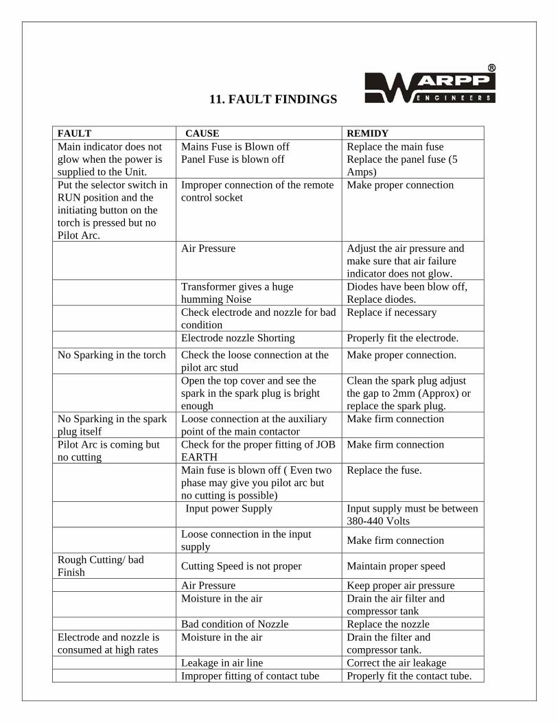
11. FAULT FINDINGS
FAULT CAUSE REMIDY Main indicator does not glow when the power is supplied to the Unit.
Mains Fuse is Blown off Panel Fuse is blown off
Replace the main fuse Replace the panel fuse (5 Amps)
Put the selector switch in RUN position and the initiating button on the torch is pressed but no Pilot Arc.
Improper connection of the remote control socket
Make proper connection
Air Pressure Adjust the air pressure and make sure that air failure indicator does not glow.
Transformer gives a huge humming Noise
Diodes have been blow off, Replace diodes.
Check electrode and nozzle for bad condition
Replace if necessary
Electrode nozzle Shorting Properly fit the electrode. No Sparking in the torch Check the loose connection at the
pilot arc stud Make proper connection.
Open the top cover and see the spark in the spark plug is bright enough
Clean the spark plug adjust the gap to 2mm (Approx) or replace the spark plug.
No Sparking in the spark plug itself
Loose connection at the auxiliary point of the main contactor
Make firm connection
Pilot Arc is coming but no cutting
Check for the proper fitting of JOB EARTH
Make firm connection
Main fuse is blown off ( Even two phase may give you pilot arc but no cutting is possible)
Replace the fuse.
Input power Supply Input supply must be between 380-440 Volts
Loose connection in the input supply Make firm connection
Rough Cutting/ bad Finish Cutting Speed is not proper Maintain proper speed
Air Pressure Keep proper air pressure Moisture in the air Drain the air filter and
compressor tank Bad condition of Nozzle Replace the nozzle Electrode and nozzle is consumed at high rates
Moisture in the air Drain the filter and compressor tank.
Leakage in air line Correct the air leakage Improper fitting of contact tube Properly fit the contact tube.