Manual-ECO.55S.TA-EOV-1.1-2010-1.pdf - Euroboor
41
User manual V 1.1 EN | October 2021 Automatic magnetic drilling machine with 2-way electromagnet ECO.55S+/TA
-
Upload
khangminh22 -
Category
Documents
-
view
1 -
download
0
Transcript of Manual-ECO.55S.TA-EOV-1.1-2010-1.pdf - Euroboor

User manual
V 1.1 EN | October 2021
Automatic magnetic drilling machine with 2-way electromagnet
ECO.55S+/TA

2
Congratulations on purchasing this premium magnetic drilling machine. At EUROBOOR we strive to
exceed our customers’ expectations by developing and providing premium and innovative portable
drilling and cutting solutions. We believe that a professional like you must be able to rely on a
professional supplier. Which has led us to become a major player in the industrial world, with our
own factory and several offices worldwide. All because we have always listened to our customers
and to the demands from the market.
Our vision is focused on developing innovative portable tools that add value for our customers and
facilitate them in their daily work. We never lose sight of sustainability, time savings and cost savings.
Enjoy your new machine!
Before operating your new magnetic drilling machine, please first read all instructions. You find the
instructions in this manual and on the warning label on your machine. With proper use, care and
maintenance your machine will provide you with years of premium drilling performance.
TO REDUCE THE RISK OF INJURY USER MUST READ AND UNDERSTAND ALL INSTRUCTIONS
To view all our offices and their contact information please visit: www.euroboor.com
The original manual has been produced in the English language. If any discrepancies should occur in
translations, reference must be made to the original version for clarification.
3
Table of contents
ECO.55S+/TA ................................................................................................................................ 1
Table of contents ......................................................................................................................... 3
1. Safety ....................................................................................................................................... 4
1.1 General safety instructions ........................................................................................................... 4
1.2 Specific safety information ............................................................................................................ 6
2. Description ............................................................................................................................... 8
2.1 Intended use .................................................................................................................................. 8
2.2 Description and features ............................................................................................................... 8
2.3 Case content .................................................................................................................................. 9
2.4 Serial number ................................................................................................................................ 9
2.5 Technical data.............................................................................................................................. 10
2.6 Symbols ....................................................................................................................................... 11
2.7 Environmental ............................................................................................................................. 12
3. Preparation & adjustment ...................................................................................................... 13
3.1 Assembly ..................................................................................................................................... 13
3.2 Prior to use .................................................................................................................................. 14
4. Using the machine .................................................................................................................. 16
4.1 Control panel ............................................................................................................................... 16
4.2 Morse taper arbor ....................................................................................................................... 17
4.3 2-Way electromagnet .................................................................................................................. 17
4.4 2-Speed gearbox .......................................................................................................................... 19
4.5 Switching motor on and off ......................................................................................................... 19
4.6 Automatic drilling functionality ................................................................................................... 20
4.7 Overload protection and Smart restart ....................................................................................... 21
4.8 Motor rotation ............................................................................................................................ 22
4.9 Motor speed control ................................................................................................................... 22
4.10 Overheat protection .................................................................................................................. 22
4.11 GYRO-TEC safety ........................................................................................................................ 22
4.12 Power protection....................................................................................................................... 23
4.13 Carbon brushes ......................................................................................................................... 24
4.14 Tool lubrication ......................................................................................................................... 24
5. Working with drilling accessories ............................................................................................ 25
5.1 Annular cutters ............................................................................................................................ 25
5.2 Twist drills .................................................................................................................................... 26
5.3 Machine taps ............................................................................................................................... 28
5.4 Countersinks ................................................................................................................................ 29
6. Maintenance .......................................................................................................................... 30
7. Trouble shooting .................................................................................................................... 32
8. Exploded views & spare parts list ............................................................................................ 34
8.1 Exploded views ............................................................................................................................ 34
8.2 Spare parts list ............................................................................................................................. 37
8.3 Wiring diagrams 110V and 220V ................................................................................................. 40
8.4 Warranty and service .................................................................................................................. 41
4
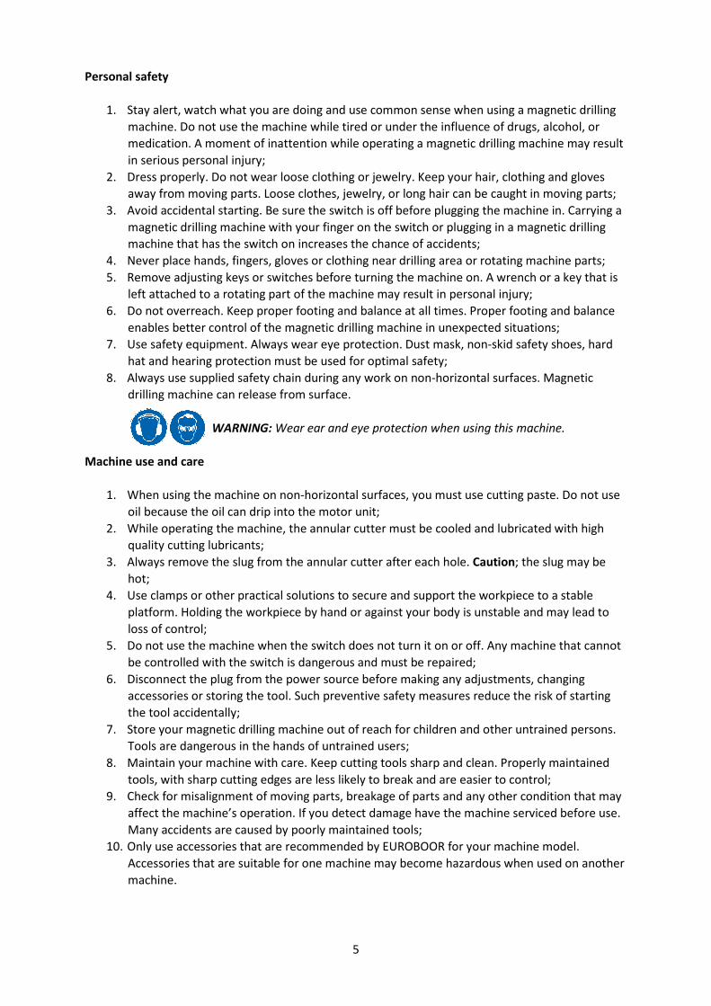
1. Safety
1.1 General safety instructions
Do not use this magnetic drilling machine before you have thoroughly read and completely
understood this manual, specifically the “General safety instructions” and ‘’Specific safety
information’’, including the figures, specifications, safety regulations and the signs indicating
DANGER, WARNING and CAUTION.
WARNING: When using electrical tools basic safety precautions should always be followed to
reduce the risk of fire, electrical shock and personal injury.
Please also observe the relevant national industrial safety regulations. Non-observance of the safety
instructions can lead to an electric shock, burns and/or severe injuries.
This manual should be kept for later use and enclosed with the magnetic drilling machine, should it
be passed on or sold.
Work area
1. Keep your work area clean and well lit. Cluttered and dark work areas increase the chance of
accidents;
2. Do not operate a magnetic drilling machine in explosive atmospheres, such as in the
presence of flammable liquids, gases or dust. A magnetic drilling machine may create sparks
which could ignite the dust or fumes;
3. Keep bystanders, children and visitors away while operating a magnetic drilling machine.
Distractions can cause you to lose control.
Electrical safety
1. A magnetic drilling machine plug must match the outlet. Never modify the plug in any way.
Do not us any adapter plugs;
2. Avoid body contact with grounded surfaces such as pipes, radiators, ranges and refrigerators.
There is an increased risk of electric shock if your body is grounded;
3. Do not expose the magnetic drilling machine to rain or wet conditions. Water entering a
machine will increase the risk of electric shock;
4. Do not abuse the cord. Never use the cord to carry the magnetic drilling machine or pull the
plug from an outlet. Keep the cord away from heat, oil, sharp edges or moving parts. Replace
damaged cords immediately. Damaged cords increase the risk of electric shock;
5. When operating a magnetic drilling machine, use an extension cord suitable for outdoor use,
this reduces the risk of electric shock;
6. If operating a magnetic drilling machine in a damp location is unavoidable, use a residual
current device (RCD), this reduces the risk of electric shock.
5
Personal safety
1. Stay alert, watch what you are doing and use common sense when using a magnetic drilling
machine. Do not use the machine while tired or under the influence of drugs, alcohol, or
medication. A moment of inattention while operating a magnetic drilling machine may result
in serious personal injury;
2. Dress properly. Do not wear loose clothing or jewelry. Keep your hair, clothing and gloves
away from moving parts. Loose clothes, jewelry, or long hair can be caught in moving parts;
3. Avoid accidental starting. Be sure the switch is off before plugging the machine in. Carrying a
magnetic drilling machine with your finger on the switch or plugging in a magnetic drilling
machine that has the switch on increases the chance of accidents;
4. Never place hands, fingers, gloves or clothing near drilling area or rotating machine parts;
5. Remove adjusting keys or switches before turning the machine on. A wrench or a key that is
left attached to a rotating part of the machine may result in personal injury;
6. Do not overreach. Keep proper footing and balance at all times. Proper footing and balance
enables better control of the magnetic drilling machine in unexpected situations;
7. Use safety equipment. Always wear eye protection. Dust mask, non-skid safety shoes, hard
hat and hearing protection must be used for optimal safety;
8. Always use supplied safety chain during any work on non-horizontal surfaces. Magnetic
drilling machine can release from surface.
WARNING: Wear ear and eye protection when using this machine.
Machine use and care
1. When using the machine on non-horizontal surfaces, you must use cutting paste. Do not use
oil because the oil can drip into the motor unit;
2. While operating the machine, the annular cutter must be cooled and lubricated with high
quality cutting lubricants;
3. Always remove the slug from the annular cutter after each hole. Caution; the slug may be
hot;
4. Use clamps or other practical solutions to secure and support the workpiece to a stable
platform. Holding the workpiece by hand or against your body is unstable and may lead to
loss of control;
5. Do not use the machine when the switch does not turn it on or off. Any machine that cannot
be controlled with the switch is dangerous and must be repaired;
6. Disconnect the plug from the power source before making any adjustments, changing
accessories or storing the tool. Such preventive safety measures reduce the risk of starting
the tool accidentally;
7. Store your magnetic drilling machine out of reach for children and other untrained persons.
Tools are dangerous in the hands of untrained users;
8. Maintain your machine with care. Keep cutting tools sharp and clean. Properly maintained
tools, with sharp cutting edges are less likely to break and are easier to control;
9. Check for misalignment of moving parts, breakage of parts and any other condition that may
affect the machine’s operation. If you detect damage have the machine serviced before use.
Many accidents are caused by poorly maintained tools;
10. Only use accessories that are recommended by EUROBOOR for your machine model.
Accessories that are suitable for one machine may become hazardous when used on another
machine.
6
Service
1. Tool service must be performed only by qualified repair personnel. Service or maintenance
performed by unqualified personnel could result in risk of injury;
2. When servicing a tool, use only identical replacement parts. Follow instructions in the
maintenance section of this manual. Use of unauthorised parts or failure to follow
maintenance instructions may create a risk of electric shock or injury;
3. EUROBOOR offers Armature kits containing official EUROBOOR spare parts suitable for your
magnetic drilling machine.
1.2 Specific safety information
• Keep your fingers away from the drilling area;
• Avoid touching the slug that is automatically ejected by the pilot pin when the working
procedure is finished. Contact with the slug when it is hot, or if it falls, can cause personal
injuries;
• Always use the safety guard. Before switching on the machine ensure that the guard is closed
securely;
• Always use the safety chain;
• The magnetic drilling machine is suitable for use on steel with a thickness starting from 6 mm,
with zero air gap between the magnet core surface and the mounting surface. Curvature,
coats of paint and surface irregularities will create an air gap. Keep the air gap to a minimum;
• Always place the machine on a flat surface;
• Do not clamp the magnetic drilling machine on small or irregular shaped objects;
• Always place the machine on a surface that is clear of shavings, chips, swarf and surface dirt;
• Keep the magnet clean and free of debris and swarf;
• Do not switch on the machine before checking whether the magnetic stand has been
tightened firmly to the mounting surface;
• Adjust the machine so cutter does not extend into the workpiece before drilling. Do not
perform any design, assembly or construction activities on the workpiece while the machine is
switched on;
• Before switching on the machine, make sure all accessories have been mounted correctly;
• Do not switch on the machine until it has been mounted and installed according to all above
mentioned instructions;
• Always use the recommended speed for the accessories and material you are working with;
• Do not use the machine on the same workpiece on which electric welders are working;
• Only use an appropriate cutting lubricant. EUROBOOR offers a wide range of well-considered
cooling and lubrication products to match your requirements;
• Do not use liquid cutting fluids while drilling vertically or overhead. Dip the cutter in cutting
paste or apply an appropriate spray for these applications;
• Do not pour cutting fluid into the reservoir while it is mounted in the bracket. Do not allow
cutting fluid to enter the drill motor;
• Before use, ensure movable safety guard operates properly;
• In case of a jammed cutter, turn of the machine, disconnect the machine from the power
supply and then remove the reason for the jam before turning on the machine again.

7
Residual risk
In spite of following the relevant safety regulations and their implementation, certain residual risks
cannot be avoided. These are:
• Impairment of hearing;
• Risk of personal injury from flying particles;
• Risk of burns due to accessories becoming hot during operation;
• Risk of personal injury due to prolonged use.
Always try to reduce these risks as much as possible.
8
2. Description
2.1 Intended use
This magnetic drilling machine is intended for commercial use as an automatic drilling machine for
drilling materials with a magnetisable surface using annular cutters and twist drills, and for tapping
and countersinking in a weather-protected environment using the application tools and accessories
recommended by EUROBOOR. The magnetic drilling machine can be used horizontally, vertically or
overhead.
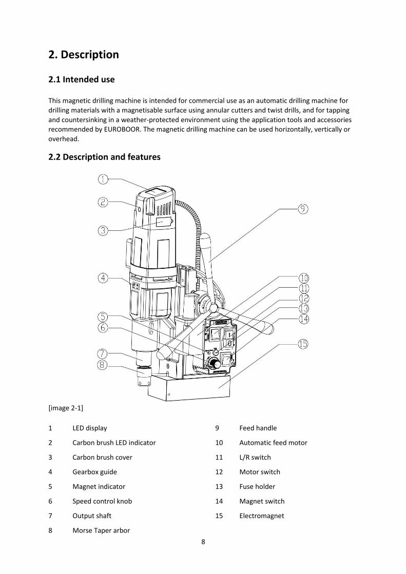
2.2 Description and features
[image 2-1]
1 LED display
2 Carbon brush LED indicator
3 Carbon brush cover
4 Gearbox guide
5 Magnet indicator
6 Speed control knob
7 Output shaft
8 Morse Taper arbor
9 Feed handle
10 Automatic feed motor
11 L/R switch
12 Motor switch
13 Fuse holder
14 Magnet switch
15 Electromagnet
2.3 Case content
1 x ECO.55S+/TA Magnetic drilling machine
1 x safety guard
3 x handles
4 x tap holder (Weldon) M10, M12, M14, M16 (DIN 376) or 3/8”, 7/16”, 1/2”, 5/8” (ANSI)
1 x hex key 2.5 mm
1 x hex key 4 mm
1 x hex key 5 mm
1 x lubrication system
1 x safety chain
1 x bottle (200 ml) of IBO.10 cutting oil
1 x arbor MT 3 - 19.05 (3/4"), including lubrication ring (IMC.30/19-N)
1 x Morse taper ejector drift key
1 x user manual
1 x safety ear protection
1 x safety goggles
1 x safety gloves
2.4 Serial number
The serial number is mentioned on the machine three times: engraved on the frame, engraved on
the magnet and on the serial no. sticker on the motor housing. Additional serial no. stickers are
provided with the machine for your administration.
The serial number will help you, your dealer and EUROBOOR to validate and identify the machine.
For example:
0552010001
breaks down to:
055 20 10 001
Machine series
Year of manufacture
Month of manufacture
Identification number
10
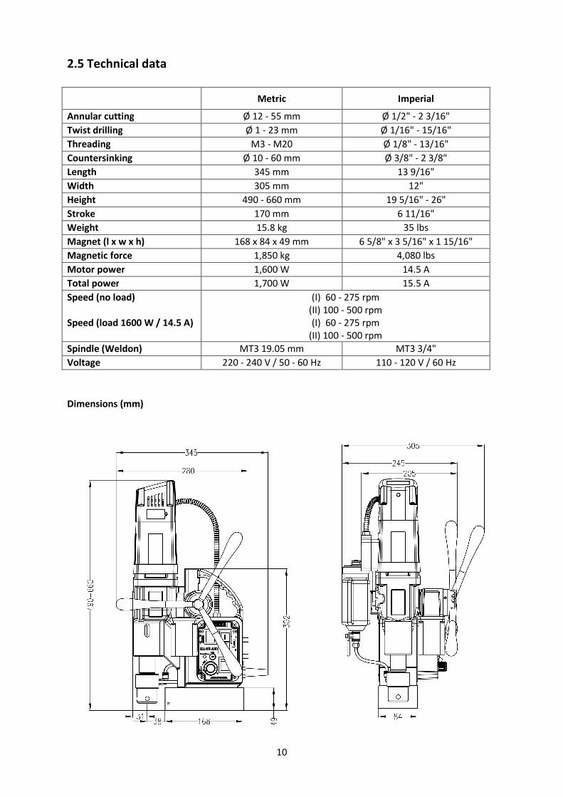
2.5 Technical data
Metric Imperial
Annular cutting Ø 12 - 55 mm Ø 1/2" - 2 3/16"
Twist drilling Ø 1 - 23 mm Ø 1/16" - 15/16"
Threading M3 - M20 Ø 1/8" - 13/16"
Countersinking Ø 10 - 60 mm Ø 3/8" - 2 3/8"
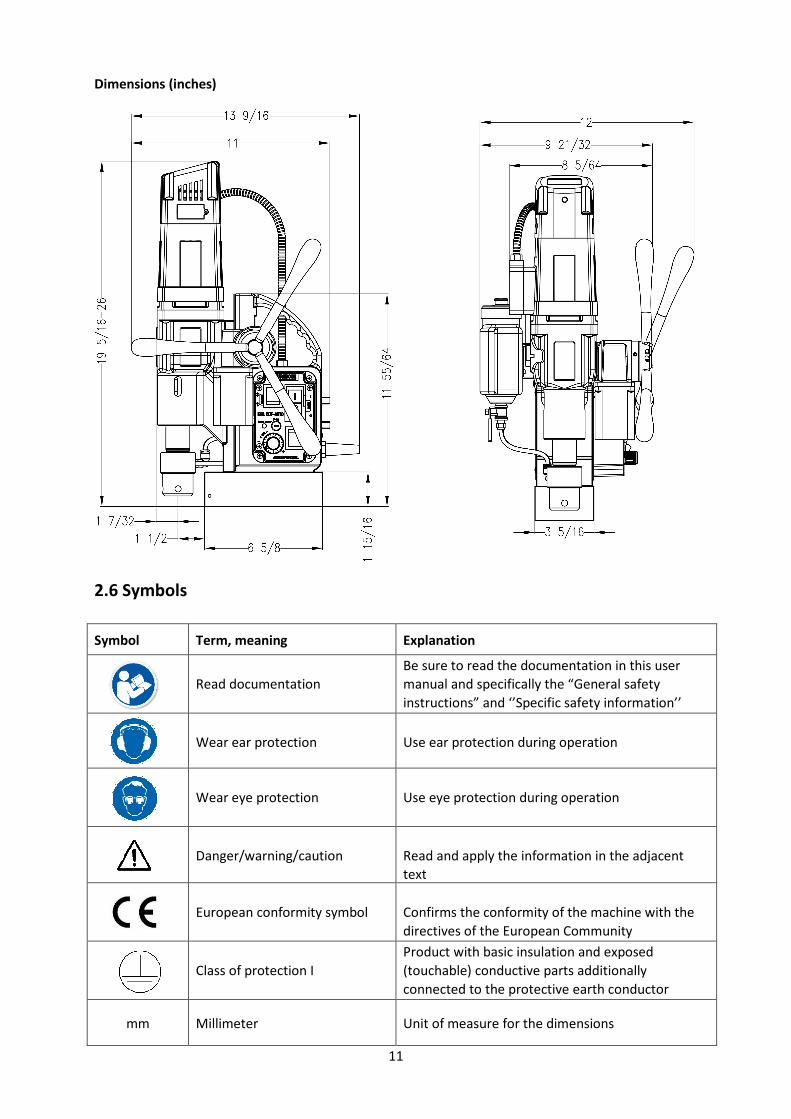
Length 345 mm 13 9/16"
Width 305 mm 12"
Height 490 - 660 mm 19 5/16" - 26"
Stroke 170 mm 6 11/16"
Weight 15.8 kg 35 lbs
Magnet (l x w x h) 168 x 84 x 49 mm 6 5/8" x 3 5/16" x 1 15/16"
Magnetic force 1,850 kg 4,080 lbs
Motor power 1,600 W 14.5 A
Total power 1,700 W 15.5 A
Speed (no load)
Speed (load 1600 W / 14.5 A)
(I) 60 - 275 rpm
(II) 100 - 500 rpm
(I) 60 - 275 rpm
(II) 100 - 500 rpm
Spindle (Weldon) MT3 19.05 mm MT3 3/4"
Voltage 220 - 240 V / 50 - 60 Hz 110 - 120 V / 60 Hz
Dimensions (mm)
11
Dimensions (inches)
2.6 Symbols
Symbol Term, meaning Explanation
Read documentation
Be sure to read the documentation in this user
manual and specifically the “General safety
instructions” and ‘’Specific safety information’’
Wear ear protection
Use ear protection during operation
Wear eye protection
Use eye protection during operation
Danger/warning/caution
Read and apply the information in the adjacent
text
European conformity symbol
Confirms the conformity of the machine with the
directives of the European Community
Class of protection I
Product with basic insulation and exposed
(touchable) conductive parts additionally
connected to the protective earth conductor
mm Millimeter Unit of measure for the dimensions
12
Symbol Term, meaning Explanation
" Inch Unit of measure for the dimensions
kg Kilogram Unit of measure for the mass
lbs Pound Unit of measure for the mass
V Volt Unit of measure for the electric voltage
A Ampere Unit of measure for the electric current intensity
W Watt Unit of measure for the output
no No load speed Revolution speed at no load
rpm Revolutions per minute Unit of measure for the revolutions
2.7 Environmental
Separate collection. This product must not be disposed of with normal household waste.
Separate collection of used products and packaging allows materials to be recycled and used
again. Re-use of recycled materials helps prevent environmental pollution and reduces the
demand for raw materials.
Local regulations may provide for separate collection of electrical products from the household, at
municipal waste sites or at the retailer when you purchase a new product.
13
3. Preparation & adjustment
3.1 Assembly
WARNING: To reduce the risk of injury, turn machine off and disconnect from power source
before installing and removing accessories, before adjusting or changing set-ups or when
making repairs. Be sure all switches are in the OFF position. An accidental start-up can cause
injury.
Fitting the feed handles
1. Fit each of the three feed handles by screwing them into the hub in clockwise direction;
2. Tighten firmly by hand.
The handles are supposed to face slightly outward. Be careful not to cross-thread any of the
components.
Mounting the safety guard
The safety guard protects against chippings and accidental contact and must always be mounted
before operation:
1. Hold the guard in front of the magnet, align the slots in the guard with the holes in the
magnet;
2. Fit the screws into the holes located in the side of the magnet.
WARNING: Always use the safety guard.
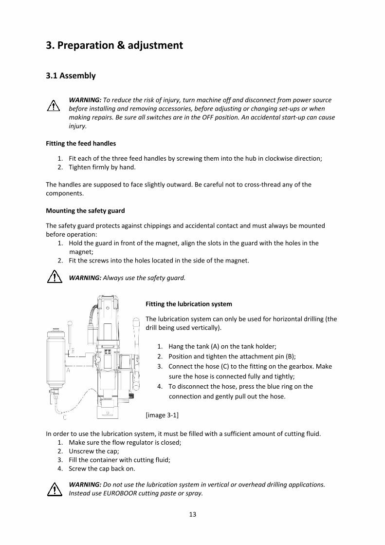
Fitting the lubrication system
The lubrication system can only be used for horizontal drilling (the
drill being used vertically).
1. Hang the tank (A) on the tank holder;
2. Position and tighten the attachment pin (B);
3. Connect the hose (C) to the fitting on the gearbox. Make
sure the hose is connected fully and tightly;
4. To disconnect the hose, press the blue ring on the
connection and gently pull out the hose.
[image 3-1]
In order to use the lubrication system, it must be filled with a sufficient amount of cutting fluid.
1. Make sure the flow regulator is closed;
2. Unscrew the cap;
3. Fill the container with cutting fluid;
4. Screw the cap back on.
WARNING: Do not use the lubrication system in vertical or overhead drilling applications.
Instead use EUROBOOR cutting paste or spray.
14
Fitting the safety chain
1. Pass the safety chain through the frame grip opening;
2. Wrap the chain around the workpiece;
3. Securely close the chain using the lock.
WARNING: Always use the safety chain when drilling vertically and/or upside down. The
safety chain does not replace the magnetic force of the magnetic drilling machine: it is simply
used to secure against falling in the event of a magnet malfunction.
3.2 Prior to use
Please make sure that the contacting surface for the magnet is level, clean and rust free.
Remove any varnish or primer. When working on materials that are not magnetisable, suitable
fixation devices, obtainable as accessories from EUROBOOR, e. g. suction plate, vacuum plate or
pipe-drilling machine must be used.
When working on steel materials with a material thickness of less than 6 mm, the workpiece must
be reinforced with an additional steel plate in order to guarantee the magnetic holding power.
Check the machine for possible damage; Before using the machine, you must carefully check the
protective components or slightly damaged components to ensure they are operating perfectly and
as intended.
Check that moving parts are in perfect working order, do not jam and check whether the parts are
damaged. All parts must be correctly installed and fulfill all conditions necessary to ensure perfect
operation of the machine.
Damaged protective components must be repaired or replaced according to specifications by
EUROBOOR or any authorised EUROBOOR dealer.
DO NOT use under wet conditions or in presence of flammable liquids or gases.
DO NOT let children come into contact with the machine. Supervision is required when
inexperienced operators use this machine.
Electrical safety
The electric motor has been designed for one voltage only. Always check that the power supply
corresponds to the voltage on the rating plate.
Your EUROBOOR magnetic drilling machine is designed in class I (grounded) according to EN 61029-1.
Earth wire is required.
If the supply cord is damaged, it must be replaced by a specially prepared cord available at
EUROBOOR or your EUROBOOR dealer.
Extension cable
If an extension cable is required, use an approved 3-core extension cable suitable for the power input
of this machine (see technical data).The minimum conductor size is 1.5 mm²; the maximum length is
30 metre. When using a cable reel, always unwind the cable completely.

15
Useful tips
– Try a few simple projects using scrap material until you develop a ‘’feel’’ for the magnetic
drilling machine;
– Let the machine run in for a period of eight to ten hours before starting with big operations.
Do not load the machine too much during this run-in period;
– Never use the machine with serious overload;
– Keep the machine clear from moisture at all times to protect the machine, yourself and
others.
.
16
4. Using the machine
WARNING: Always observe the safety instructions and applicable regulations.
WARNING: To reduce the risk of serious personal injury, turn the machine off and disconnect
the machine from power source before making any adjustments or removing/installing
attachments or accessories.
4.1 Control panel
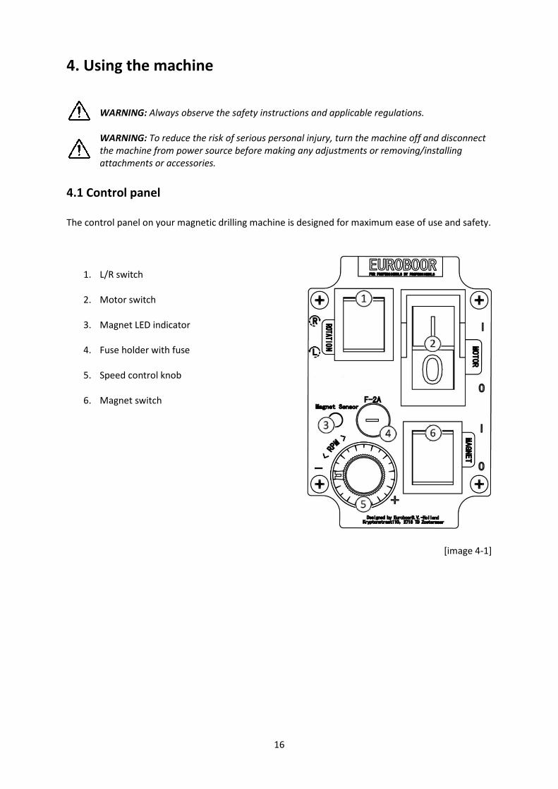
The control panel on your magnetic drilling machine is designed for maximum ease of use and safety.
1. L/R switch
2. Motor switch
3. Magnet LED indicator
4. Fuse holder with fuse
5. Speed control knob
6. Magnet switch
[image 4-1]
17
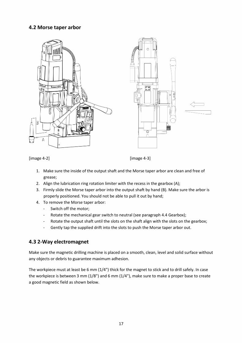
4.2 Morse taper arbor
[image 4-2] [image 4-3]
1. Make sure the inside of the output shaft and the Morse taper arbor are clean and free of
grease;
2. Align the lubrication ring rotation limiter with the recess in the gearbox (A);
3. Firmly slide the Morse taper arbor into the output shaft by hand (B). Make sure the arbor is
properly positioned. You should not be able to pull it out by hand;
4. To remove the Morse taper arbor:
- Switch off the motor;
- Rotate the mechanical gear switch to neutral (see paragraph 4.4 Gearbox);
- Rotate the output shaft until the slots on the shaft align with the slots on the gearbox;
- Gently tap the supplied drift into the slots to push the Morse taper arbor out.
4.3 2-Way electromagnet
Make sure the magnetic drilling machine is placed on a smooth, clean, level and solid surface without
any objects or debris to guarantee maximum adhesion.
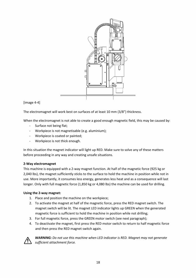
The workpiece must at least be 6 mm (1/4") thick for the magnet to stick and to drill safely. In case
the workpiece is between 3 mm (1/8") and 6 mm (1/4"), make sure to make a proper base to create
a good magnetic field as shown below.
18
[image 4-4]
The electromagnet will work best on surfaces of at least 10 mm (3/8") thickness.
When the electromagnet is not able to create a good enough magnetic field, this may be caused by:
- Surface not being flat;
- Workpiece is not magnetisable (e.g. aluminium);
- Workpiece is coated or painted;
- Workpiece is not thick enough.
In this situation the magnet indicator will light up RED. Make sure to solve any of these matters
before proceeding in any way and creating unsafe situations.
2-Way electromagnet
This machine is equipped with a 2-way magnet function. At half of the magnetic force (925 kg or
2,040 lbs), the magnet sufficiently sticks to the surface to hold the machine in position while not in
use. More importantly, it consumes less energy, generates less heat and as a consequence will last
longer. Only with full magnetic force (1,850 kg or 4,080 lbs) the machine can be used for drilling.
Using the 2-way magnet:
1. Place and position the machine on the workpiece;
2. To activate the magnet at half of the magnetic force, press the RED magnet switch. The
magnet switch will be lit. The magnet LED indicator lights up GREEN when the generated
magnetic force is sufficient to hold the machine in position while not drilling;
3. For full magnetic force, press the GREEN motor switch (see next paragraph);
4. To deactivate the magnet, first press the RED motor switch to return to half magnetic force
and then press the RED magnet switch again.
WARNING: Do not use this machine when LED indicator is RED. Magnet may not generate
sufficient attachment force.
19
We want to point out that above mentioned precautions and indicators do not guarantee that the
magnet will not release from the material. EUROBOOR accepts no liability when it comes to the
magnet indicator not functioning or functioning poorly.
Make sure that the magnet attaches tightly to the work piece before turning on the motor unit of the
magnetic drilling machine. EUROBOOR magnets have two coils; make sure that both coils are in
contact with the material. Do not connect any other machine to the same electrical outlet to which
the magnetic drilling machine is plugged into, as it may result in the loss of magnetic force.
Always use the safety chain included. Drilling above your head is extremely dangerous and is not
recommended. For the use of magnetic drilling machines on pipes, not-flat or non-magnetic
materials, we refer to our catalogue or our website www.euroboor.com where several vacuum
tightening systems, pipe clamping systems and Tube machines can be found.
4.4 2-Speed gearbox
1. To select the correct gear from neutral (horizontal) position:
a. Rotate the switch counter clockwise to position o, this is gear 1;
b. Rotate the switch clockwise to position oo, this is gear 2;
2. A gear is only correctly selected when the gearbox switch is aligned with the indicators on
the gearbox;
In case you have trouble fully and correctly selecting a gear, the gears in the gearbox might
be misaligned. Slightly rotating the output shaft by hand will help you align the gears and
correctly and fully select the intended gear.
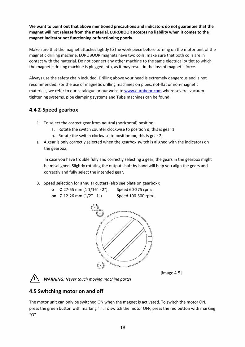
3. Speed selection for annular cutters (also see plate on gearbox):
o Ø 27-55 mm (1 1/16" - 2") Speed 60-275 rpm;
oo Ø 12-26 mm (1/2" - 1") Speed 100-500 rpm.
[image 4-5]
WARNING: Never touch moving machine parts!
4.5 Switching motor on and off
The motor unit can only be switched ON when the magnet is activated. To switch the motor ON,
press the green button with marking “I”. To switch the motor OFF, press the red button with marking
“O”.
20
4.6 Automatic drilling functionality
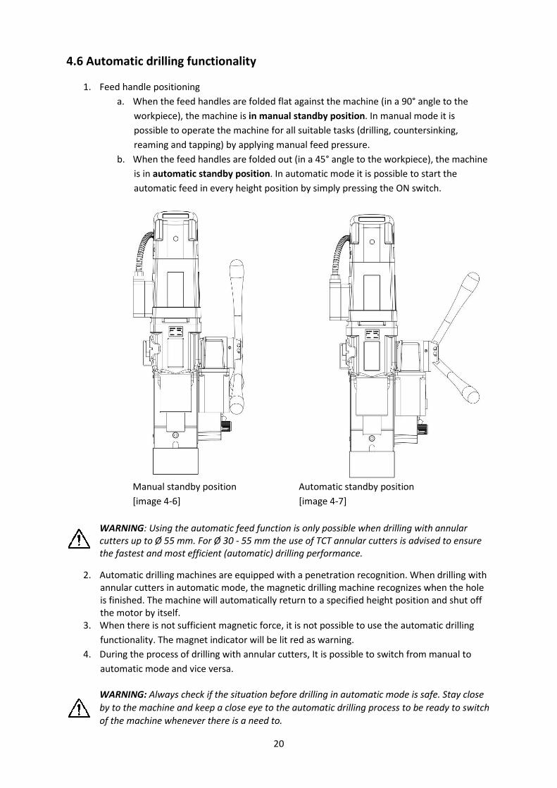
1. Feed handle positioning
a. When the feed handles are folded flat against the machine (in a 90° angle to the
workpiece), the machine is in manual standby position. In manual mode it is
possible to operate the machine for all suitable tasks (drilling, countersinking,
reaming and tapping) by applying manual feed pressure.
b. When the feed handles are folded out (in a 45° angle to the workpiece), the machine
is in automatic standby position. In automatic mode it is possible to start the
automatic feed in every height position by simply pressing the ON switch.
Manual standby position Automatic standby position
[image 4-6] [image 4-7]
WARNING: Using the automatic feed function is only possible when drilling with annular
cutters up to Ø 55 mm. For Ø 30 - 55 mm the use of TCT annular cutters is advised to ensure
the fastest and most efficient (automatic) drilling performance.
2. Automatic drilling machines are equipped with a penetration recognition. When drilling with
annular cutters in automatic mode, the magnetic drilling machine recognizes when the hole
is finished. The machine will automatically return to a specified height position and shut off
the motor by itself.
3. When there is not sufficient magnetic force, it is not possible to use the automatic drilling
functionality. The magnet indicator will be lit red as warning.
4. During the process of drilling with annular cutters, It is possible to switch from manual to
automatic mode and vice versa.
WARNING: Always check if the situation before drilling in automatic mode is safe. Stay close
by to the machine and keep a close eye to the automatic drilling process to be ready to switch
of the machine whenever there is a need to.

21
4.7 Overload protection and Smart restart
This machine is equipped with an electronic display, showing:
- Used motor power;
- LED indicators.
1. Switch on the electromagnet. All LED indicators shortly light up and you hear a beep;
2. Switch on the motor and start drilling. When the tool first touches the workpiece the used
motor power shown in the display increases and can be increased or decreased by raising or
reducing the pressure on the feed handles.
The LED indicators will help you drill at optimum load:
[image 4-8]
Phase 1 = A Phase 2 = B Phase 3 = C Phase 4 = D Phase 5
1 blue light 2 blue lights 2 blue lights
1 yellow light
2 blue lights
1 yellow light
1 red light
Flashing red
light + beeping
sound
Load Optimum load Acceptable
overload
Close to
overload
Overload limit
exceeded,
motor stops
Slightly increase
feed pressure
when possible
Maintain feed
pressure
Slightly reduce
feed pressure
when possible
Reduce feed
pressure
Reduce feed
pressure
When the motor is in overload (phase 5), the Smart Restart torque control technology ensures
trouble-free continuation of your drilling job. When the feed pressure is reduced, the machine’s
electronics recognize the reduction and the motor continues within a few seconds.
WARNING: The displayed motor power usage and LED indicators are only an indication of
correct cutting performance. Always keep an eye on the workpiece, tool and machine and
check if the cutting performance is as it should be.
WARNING: Never touch any potentially moving parts as long as the motor switch is still
switched on!
22
4.8 Motor rotation
For tapping, the creation of threaded holes, the rotational direction of the motor can be changed:
- Switch in up position (R) will make the motor rotate clockwise;
- Switch in down position (L) will make the motor rotate counter clockwise;
- Switch in middle position will not make the motor rotate (neutral position).
Before switching the rotational direction of the motor and spindle, make sure the motor is switched
off first, to prevent machine and tool damage.
4.9 Motor speed control
The speed control knob (potentiometer) allows you to electronically control the speed of the motor
(in both clockwise and counter clockwise direction):
- The indicator of the potentiometer in bottom left corner is minimum speed;
- The indicator of the potentiometer in bottom right corner is maximum speed;
The electronic motor speed control works for both mechanical gears. Be careful not to overturn the
knob.
4.10 Overheat protection
This machine is supplied with an all-time electronic overheat protection. If the temperature of the
motor unit runs up to 70° C (158 °F) the motor unit will stop. After a few minutes it can be started
again. When it is possible to start the motor again, let the motor run idle at full speed for a couple of
minutes to let the motor cool down more in an efficient way.
4.11 GYRO-TEC safety
This EUROBOOR magnetic drilling machine is equipped with GYRO-TEC safety functionality. It
features a gyroscopic sensor which detects acceleration and displacement in any direction.
Whenever the machine recognizes a sudden or unwanted movement the motor will be shut down
automatically by the machine’s electronics. This safety functionality offers protection to the user in
various circumstances, such as:
- Sudden loss of magnetic force while in operation;
- Excessive vibration caused by incorrect drilling procedure, worn-out cutting tools, etc;
- Sudden displacement of the workpiece to which the magnetic drilling machine is attached.
By the motor shutting down automatically, risk of damaging or hurting the machine, tools, workpiece
and operator is reduced.
Every time the motor is started, the machines electronics need a moment to run a systems check and
initiate the safety system. The GYRO-TEC safety feature engages three seconds after the motor is
started.
It is very important to note that this functionality raises the safety level, but does not prevent the
operator from using the machine incorrectly. The operator should always follow instructions
described in this manual and take all necessary safety precautions.
23
4.12 Power protection
The power protection feature is two-fold; it consists of both power fluctuation protection and power
surge protection. Special safety components built into the electronics of the machine make it more
reliable in situations where power supply can be of varying quality due to factors:
- Around the workplace, for example caused by switching on high power or unreliable
electrical devices, a broken circuit breaker or faulty wiring;
- Outside the workplace, for example caused by an instable power grid or lightning.
A machine with this feature is able to cope with standard rated voltage and frequency fluctuations
ranging from:
- 110 Volt to 130 Volt and 45 Hz to 65 Hz, or
- 220 Volt to 240 Volt and 45 Hz to 65 Hz
reducing the probability of breakdown and minimising down-time and repair cost.
Power fluctuation protection
When the frequency is too high (above 65 Hz) or too low (below 45 Hz), the motor will not start. If
the frequency of the power supply falls outside the range during your drilling job, the motor will shut
off automatically. The machine will work again normally when the normal frequency has been
restored.*
Power surge protection
Beyond the rated voltage, a machine with this feature is able to cope with voltage spikes up to 4,000
Volt (1-2μs)*. Depending on the height of the spike, it may be necessary to replace built-in fuses, the
control unit or the power switch, but other valuable parts like the motor and magnet will be
protected.
*Disclaimer: Euroboor is not liable for any damage caused to the machine due to electrical
problems in the workplace. Above mentioned protection is not guaranteed in all cases of voltage
spikes and/or frequency fluctuations. Euroboor accepts no liability when it comes to the power
protection not functioning or functioning poorly.
In the situation of the motor being shut off automatically as self-protection, you should:
- Shut off the magnet;
- Disconnect the machine from the power source;
- Fix the source of the problem, by either:
o Making sure the issues with the power source is fixed;
o Connect the machine to a different and reliable power source;
- Continue using the machine as described in this user manual.
24
4.13 Carbon brushes
This machine is equipped with carbon brushes with two protection features. The purpose of both
features is to schedule timely service and avoid additional costs by unexpected downtime or
unnecessary part replacement.
Carbon brush wear indicator
On top of the motor housing you will find an integrated LED light. Under normal circumstances this
light is off. The LED light will start burning RED when the carbon brushes are worn to a level where it
is advised to replace them.
Actual remaining operating time depends on the use of the machine, but can be up to twelve hours.
This makes it possible to schedule service of the machine and avoid unexpected downtime.
Automatic shut-off
As additional protection, when the carbon brushes are actually worn to a level where replacement is
needed, the motor will shut off automatically. This prevents the armature from being damaged.
During automatic shut-off, the carbon brush wear indicator is not lit.
For replacement of carbon brushes, see chapter 6. Maintenance.
4.14 Tool lubrication
Horizontal applications
In order to use the lubrication system, the tank must be filled with a cutting lubricant.
1. Make sure the flow regulator is closed;
2. Unscrew the cap;
3. Fill the container with cutting lubricant;
4. Screw the cap back on.
• Adjust the fluid flow as required using the flow regulator;
• Add more cutting lubricant when the shavings (metal chips) become blue.
Vertical and overhead applications
Dip the cutter in cutting paste or apply an appropriate spray.
WARNING: Do not use the lubrication system in vertical or overhead drilling applications.
Instead use EUROBOOR cutting paste.
Make sure to use only suitable cutting lubricants. EUROBOOR offers a wide range of cutting
lubricants for all tool and material combinations. Proper lubrication will help you create better and
faster results, and extend the lifetime of your tools.
25
5. Working with drilling accessories
5.1 Annular cutters
Annular cutters only cut material at the periphery of the hole, rather than converting the entire hole
to shavings. As a result, the energy required to make a hole is lower than for a twist drill. When
drilling with an annular cutter, it is not necessary to drill a pilot hole.
WARNING: Do not touch the cutter or the parts close to the cutter immediately after
operation, as they may be extremely hot and cause burns to the skin. Ensure nobody is in the
work area where the metal core is ejected.
DRILLING CONDITIONS
The ease with which material can be drilled depends on several factors including tensile strength and
abrasion resistance. Whilst hardness and/or strength is the usual criterion, wide variations in
machinability can exist among material showing similar physical properties.
The drilling conditions are dependent on requirements for tool life and surface finish. These
conditions are further restricted by the rigidity of the tool and the work piece, lubrication and
machine power available. The harder the material, the lower the cutting speed.
Some materials of low hardness contain abrasive substances leading to rapid cutting edge wear at
high speeds. Feed rates are governed by rigidity of set-up, volume of material to be removed, surface
finish and available machine power.
DRILLING A HOLE
Now that you have read the explanatory information and safety recommendations above, you are
ready to actually start drilling. Follow these 12 steps for best drilling result :
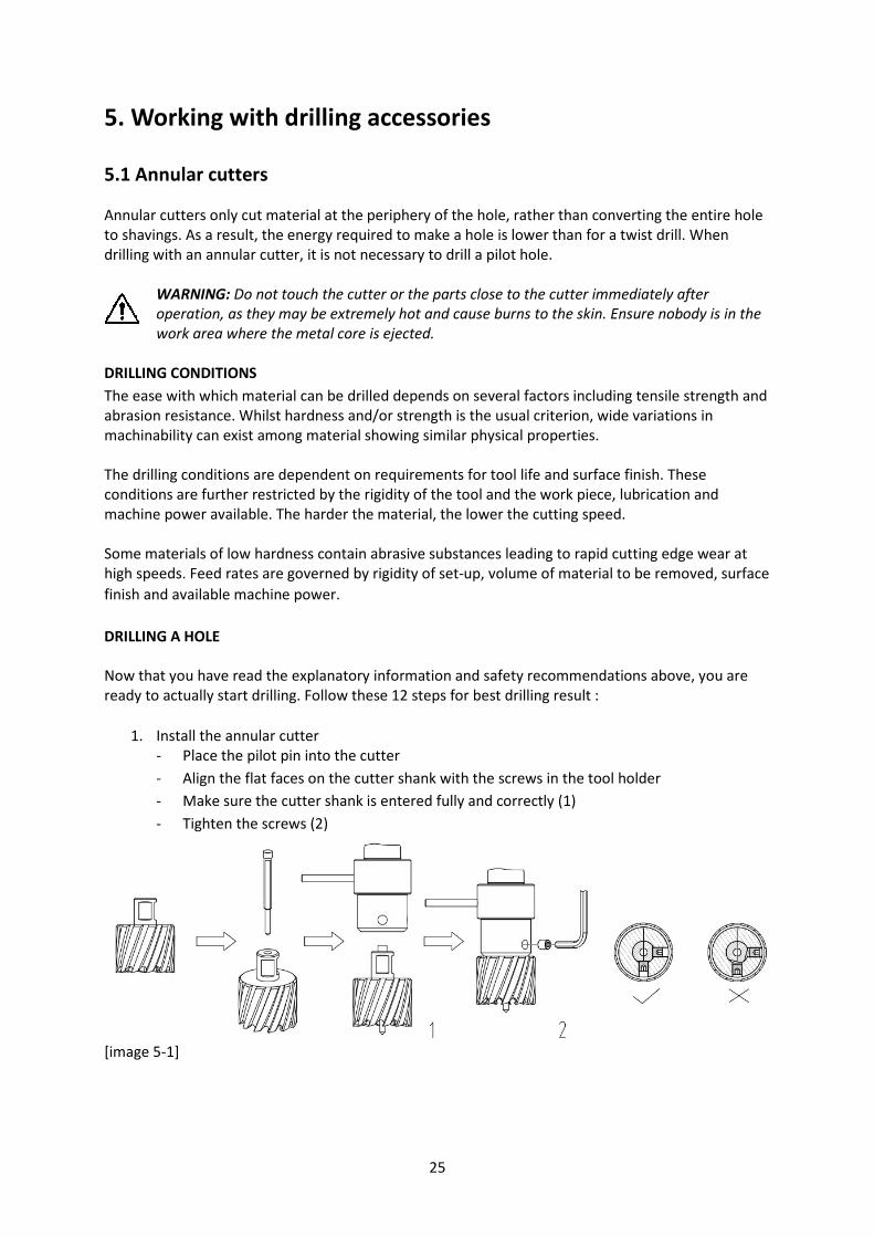
1. Install the annular cutter
- Place the pilot pin into the cutter
- Align the flat faces on the cutter shank with the screws in the tool holder
- Make sure the cutter shank is entered fully and correctly (1)
- Tighten the screws (2)
[image 5-1]
26
2. Precisely mark the centre of the hole
3. Use the pilot pin to position the machine and in the correct position, with the tip of the pilot
pin to meet the marked center of the hole.
4. Switch on the magnet and verify that the drill is in the right position and that the machine is
pushed tight against the work piece.
5. If you have installed the lubrication system, open the valve to release the oil. If not, fill the
holes of the spindle with cutting oil.
6. Switch the motor on at and allow it to run at the unloaded speed.
7. Turn the arms to start drilling. Apply only a slight pressure when the annular cutter touch the
metal. Do not push the annular cutter with force into the metal.
8. Apply regular pressure while drilling. The drilling performance does not improve by putting
more pressure on the tool. Too much pressure will overload the motor and your annular
cutter will be worn sooner.
A continuous, non-discoloured iron swarf is a sign of correct drilling speed and a well
lubricated, sharp cutter. Let the cutter do the job and give it time to cut the metal!!!
9. Adjust the oil supply when necessary. Without lubrication system, stop drilling regularly, refill
the holes of the spindle and continue drilling.
10. Apply less pressure when the drill cuts through the material. The slug will be pushed out of
the cutter by the pilot pin.
11. Turn the arms to put the motor in highest position and switch off the motor unit.
12. Remove the burrs, metal chips and clean the cutter and surface without getting injuries.
Caution: The metal slug out can be sharp and very hot!!
5.2 Twist drills
Weldon shank
Fit the twist drill with 19.05 mm (3/4") Weldon shank into the arbor and fasten the screws with the
provided Allen key.
Follow the further steps in paragraph Annular cutters.
27
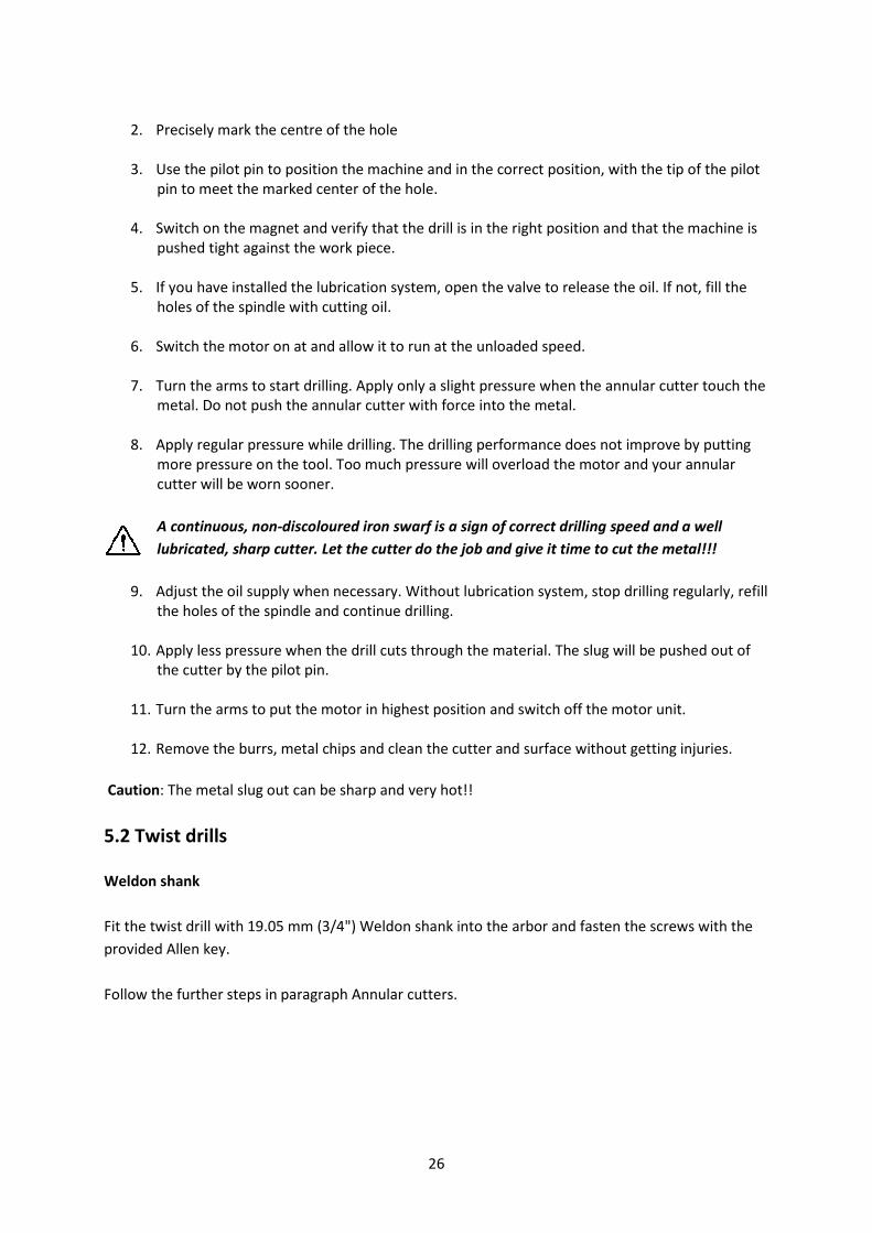
Standard parallel shank (DIN338)
1. Remove the Morse Taper 3 (MT3) arbor for Weldon shanks (see paragraph Morse Taper
arbor)
2. Fit a MT3 arbor connection
a. EUROBOOR code 1/2UNF-MC3 for 1/2" x 20 UNF drill chuck connections
b. EUROBOOR code B16-MC3 for B16 drill chuck connections
3. Fit the appropriate twist drill chuck to the arbor
4. Fit the drill with parallel shank and fasten it
[image 5-2 | Example of fastening a drill with a key]
5. Precisely mark the center of the hole, and use the tip of the twist drill to position the
machine.
For further steps see paragraph Annular cutters.
28
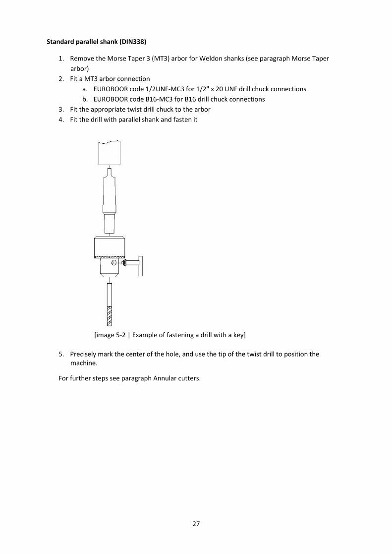
Morse Taper shanks (MT2 or MT3)
1. Remove the Morse Taper 3 (MT3) arbor for Weldon shanks (see paragraph 4.2)
2. Fit a twist drill with a MT3 shank
3. For twist drills with a MT2 shank fit an MT3-MT2 adapter (EUROBOOR code IBK.MC3-MC2)
before fitting the drill (see below)
[image 5.3 | fitting drill with MT3 shank] [image 5.4 | fitting drill with MT3-MT2 adapter]
4. Precisely mark the center of the hole, and use the tip of the twist drill to position the
machine.
For further steps see paragraph Annular cutters.
5.3 Machine taps
This machine is equipped with counter clockwise rotation and can therefore also be used for tapping.
Drill tap combination with Weldon shank
1. Fit the drill (EUROBOOR code EDT) in the spindle and fasten the 2 flats of the Weldon shank
by tightening the screws with the provided Allen key;
2. Put the feed handles in manual standby position (see paragraph 4.6);
3. Drill the required hole and tap simultaneously;
4. Proceed with step 9 in the next section.
29
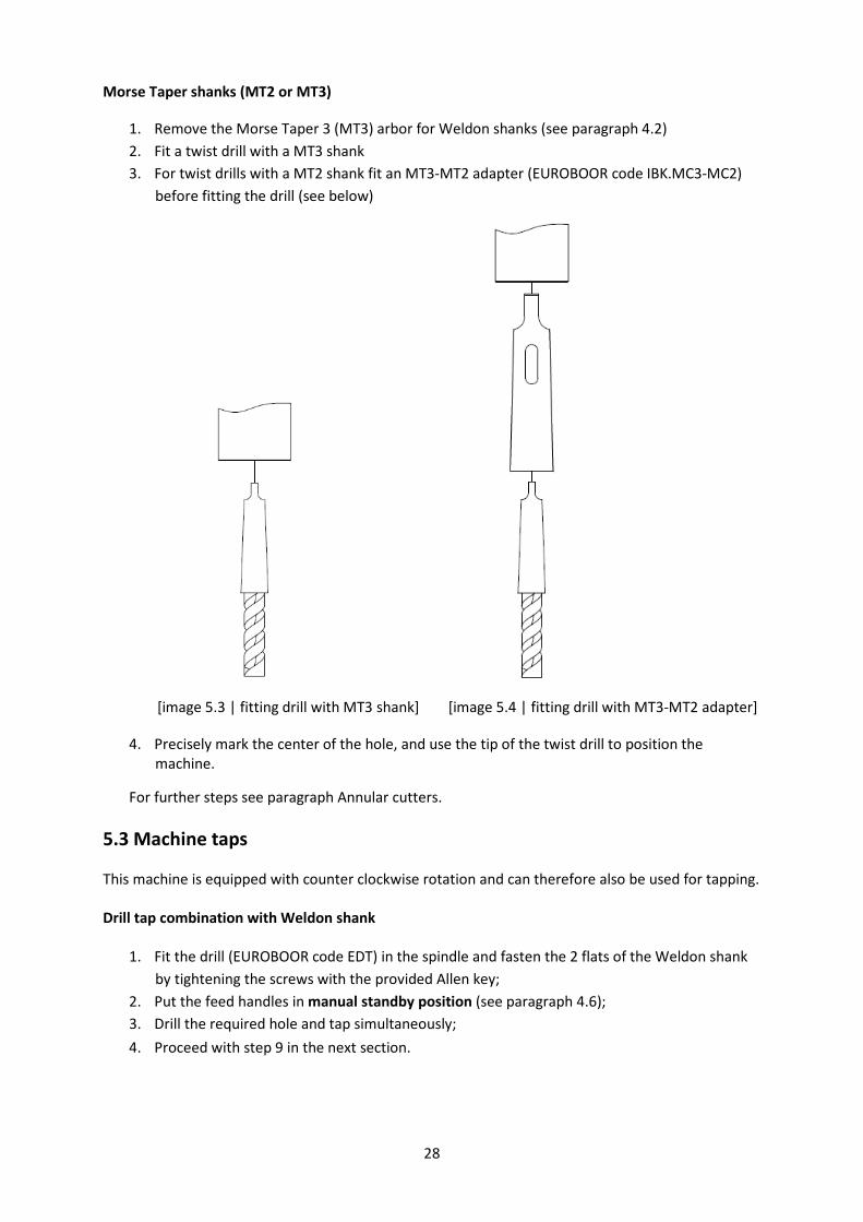
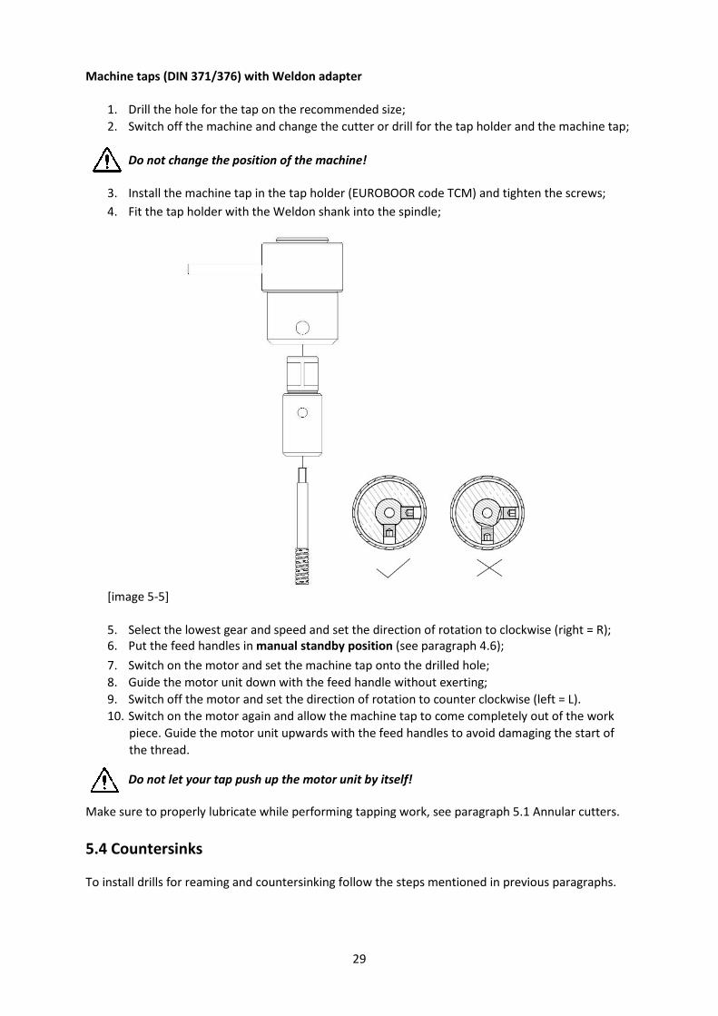
Machine taps (DIN 371/376) with Weldon adapter
1. Drill the hole for the tap on the recommended size;
2. Switch off the machine and change the cutter or drill for the tap holder and the machine tap;
Do not change the position of the machine!
3. Install the machine tap in the tap holder (EUROBOOR code TCM) and tighten the screws;
4. Fit the tap holder with the Weldon shank into the spindle;
[image 5-5]
5. Select the lowest gear and speed and set the direction of rotation to clockwise (right = R);
6. Put the feed handles in manual standby position (see paragraph 4.6);
7. Switch on the motor and set the machine tap onto the drilled hole;
8. Guide the motor unit down with the feed handle without exerting;
9. Switch off the motor and set the direction of rotation to counter clockwise (left = L).
10. Switch on the motor again and allow the machine tap to come completely out of the work
piece. Guide the motor unit upwards with the feed handles to avoid damaging the start of
the thread.
Do not let your tap push up the motor unit by itself!
Make sure to properly lubricate while performing tapping work, see paragraph 5.1 Annular cutters.
5.4 Countersinks
To install drills for reaming and countersinking follow the steps mentioned in previous paragraphs.

30
6. Maintenance
Your EUROBOOR magnetic drilling machine has been designed to operate over a long period of time.
Continuous satisfactory operation depends upon proper tool care and regular cleaning.
CAUTION: To reduce the risk of injury, turn the machine off and disconnect machine from
power source before installing and removing accessories, before adjusting or changing set-
ups or when making repairs. Be sure the switch is in the OFF position. An accidental start-
up can cause injury.
Just as every magnetic drilling machine with moving parts, your EUROBOOR magnetic drilling
machine also needs regular maintenance service. A few recommendations follow :
Visually check the machine for damage
The machine must be checked before operating for any signs of damage that will affect the operation
of the machine. Particular notice must be taken of the main cable, if the machine appears to be
damaged it should not be used. Failure to do so may cause injury or death.
Cleaning
- Clean all dirt, dust, metal chips and burrs of your magnetic drilling machine;
- Blow dirt and dust out of the main housing with dry air as often as dirt is seen collecting in and
around the air vents. Wear approved eye protection and an approved dust mask;
- Never use solvents or other harsh chemicals for cleaning the non-metallic parts of the tool.
These chemicals may weaken the materials used in these parts. Use a cloth dampened only with
water and mild soap. Never let any liquid get inside the tool; never immerse any part of the tool
into a liquid.
Operation of the machine
The machines operation must be checked to ensure that all components are working correctly.
Replace any defective parts immediately. This prevents properly functioning parts from being
damaged.
Check magnetic base
Before every operation the magnetic base should be checked to make sure that the base is flat and
there is no damage present. An uneven magnet base will cause the magnet to hold not as efficiently
and may cause injury to the operator. When the machine is put out of use for a longer period, apply
a small amount of machine oil to the underside of the magnetic base for rust protection. Clean the
magnetic base again with next use.
Check gearbox oil (IBO.G101)
The oil should be checked once a month to ensure all moving components are covered to prevent
wear. The oil should be changed at least once a year to ensure you gain the best from the machine.
Carbon brush replacement
Schedule to replace the carbon brushes when the carbon brush LED indicator lights up. The
remaining operating time depends on the use of the machine. When the carbon brushes are fully
worn, the machine will shut-off automatically. Replace the carbon brushes to get it working again.
31
Check armature
This should be checked at least once a month to check if there are visual signs of damage to the body
or to the commutator. Some signs of wear will be seen on the commutator over a period of time this
is normal as this is the part that comes in contact with the brushes but any signs of abnormal damage
means the part should be replaced.
Adjustment of slide
An essential requirement of the machine is that the slide can move in a smooth and controlled
manner, free of lateral movement and vibration.
This situation can be maintained by periodic adjustment of the slide and can be accomplished in the
following manner:
1. Place the machine in an upright position and, by means of the capstan, raise the slide to its
highest position. Clean the aluminum rails and apply a small amount of light machine oil to
the wear surfaces;
2. Gently feed in setting screw with supplied Allen key 2.5 until slight resistance is encountered.
Follow your way down adjusting all setting nuts and screws;
3. Operate the slide up and down a few times to test the movement and make any further
necessary adjustments. Try to ensure that all the screws are exerting a uniform pressure on
the slide from top to bottom. A perfectly adjusted slide will operate freely up and down
without any sideways movement.
Lubricating the feed travel
The feed travel should be lubricated periodically with grease to ensure smooth operation.
- Raise the motor unit to the highest position possible;
- Lubricate the dove-tail guideway at both sides;
- Lubricate the gear rack.
After repeated use, the gear rack may become loose. If necessary, adjust the five self-locking set
screws at the left side. Tighten screws in series until the gear rack moves freely in the dove-tail
guideway but does not allow the motor to wobble.
Repair, modification and inspection
Repair, modification and inspection of EUROBOOR Magnetic drilling machines must be done by
EUROBOOR or an EUROBOOR authorised dealer. The spare parts list will be helpful if presented with
the machine to the EUROBOOR dealer for service when requesting repair or other maintenance.
EUROBOOR machines are constantly being improved and modified to incorporate the latest
technological advancements. Accordingly, some parts (i.e. part numbers and/or design) may be
changed without prior notice. Also, due to EUROBOOR's continuing program of research and
development, the specifications of machines are subject to change without prior notice.
WARNING: Since accessories, other than those offered by EUROBOOR, have not been tested
with this machine, use of such accessories with this tool could be hazardous. To reduce the
risk of injury, only EUROBOOR recommended accessories should be used with this machine.
Consult your dealer for further information on the appropriate accessories.

32
7. Trouble shooting
Magnet and motor do not
function
- The magnet switch is not connected to the power supply
- Damaged or defective wiring
- Defective fuse
- Defective magnet switch
- Defective control unit
- Defective power supply
Magnet does function, the motor
does not work
- Damaged or defective wiring
- Carbon brushes are stuck or worn out
- Defective magnet switch
- Defective On / Off switch
- Defective control unit
- Defective armature and/or field
Magnet does not function, the
motor does
- Defective magnet
- Defective wiring of magnet
- Defective control unit
Annular cutters break quickly,
holes are bigger than the annular
cutter
- Clearance in the guide
- Bent spindle
- Shaft extending from the motor is bent
- Bent pilot pin
Motor running roughly and/or
seizing up
- Bent spindle
- Shaft extending from the motor is bent
- Triangular guide not mounted straight
- Dirt between spindle and triangular guide
Motor starts running when
magnet switch is turned on
- Damage or defective relay in control unit
Motor making a rattling sound - Gear ring (bottom of the armature) worn out
- Gear(s) worn out
- No oil in gearbox
Motor humming, big sparks and
motor has no force
- Armature damaged (burned)
- Field burned
- Carbon brushes worn out
Motor does not start or fails
- Damaged or defective wiring
- Dirt in sensor control unit
- Defective or loose magnet on top of armature
- Damaged or defective (sensor) control unit
- Damage to armature or field coil
- Damaged or defective carbon brushes
Guiding takes a great deal of
effort
- Guide is set too tight
- Guide is dry, needs to be greased
- Guide/gear- rack/rotation system dirty or damaged
Insufficient magnetic force - Damaged or defective wiring
- Bottom of magnet not clean and dry
- Bottom of magnet not flat
- Workpiece is not bare metal
- Workpiece is not clean or flat
- Workpiece is less than 6 mm (too thin)
- Defective control unit
- Defective magnet

33
Frame under voltage - Damaged / defective wiring
- Defective magnet
- Motor seriously dirty
Fuse blows when magnet switch is
turned on
- Damaged or defective wiring
- Wrong value fuse
- Defective magnet switch
- Defective control unit
- Defective magnet
Fuse blows when motor is started - Damaged or defective wiring
- Wrong value fuse
- Motor running roughly
- Defective armature and / or field
- Carbon brushes worn out
- Defective control unit
Rotation system free stroke too
long
- Loose or defective gear rack
- Defective rotation system
Red blinking light in top display
with beeping sound
- Machine is in overload protection
Red burning light in top display
with beeping sound
- Machine is in overheat protection
34
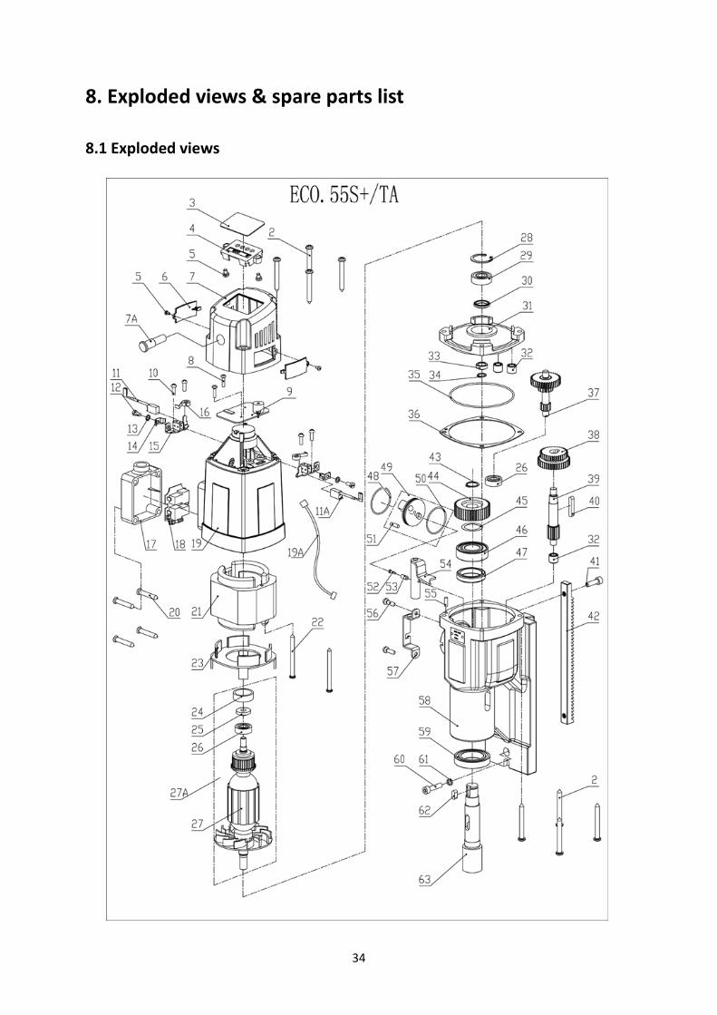
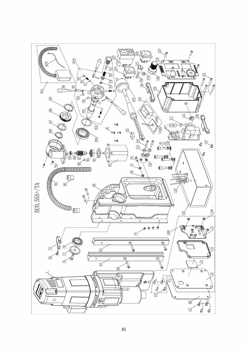
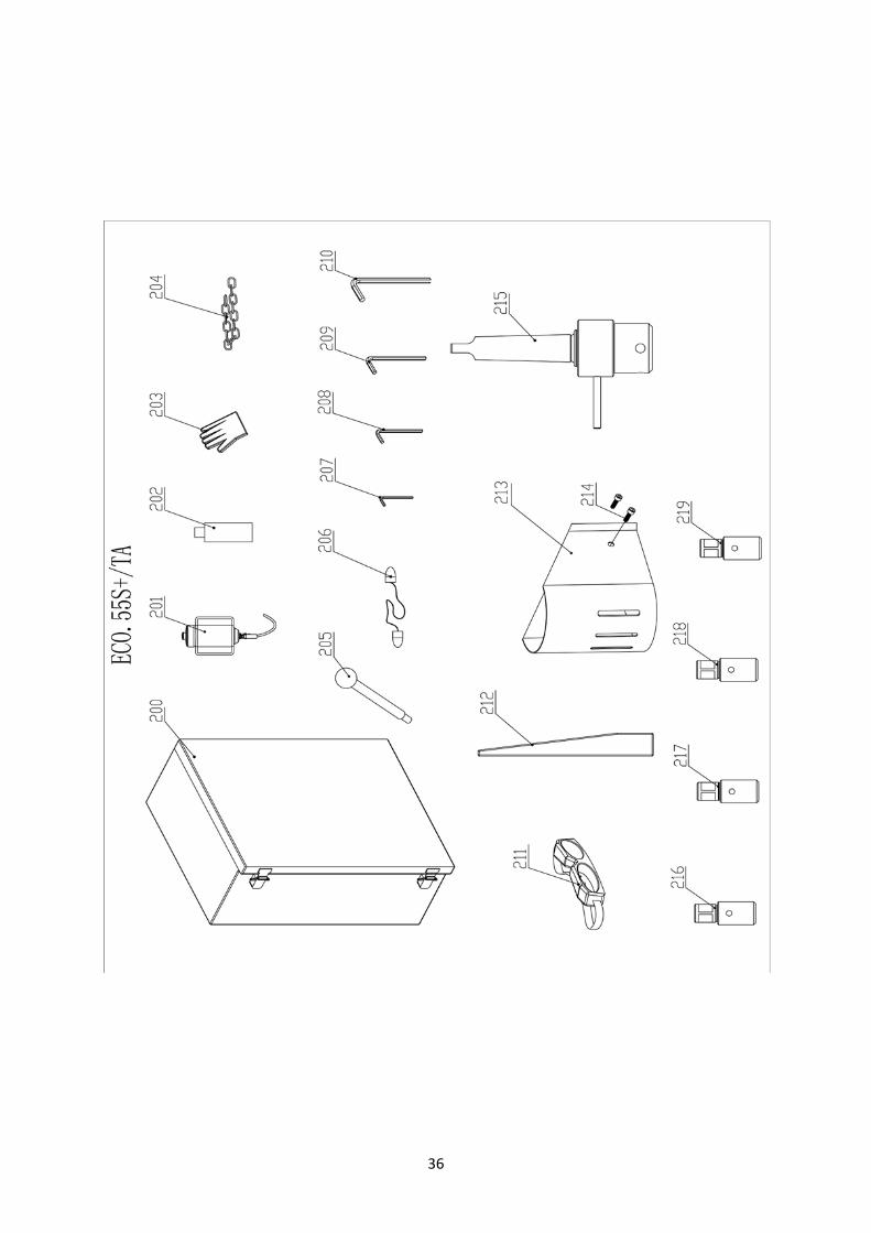
8. Exploded views & spare parts list
8.1 Exploded views
35
36
37
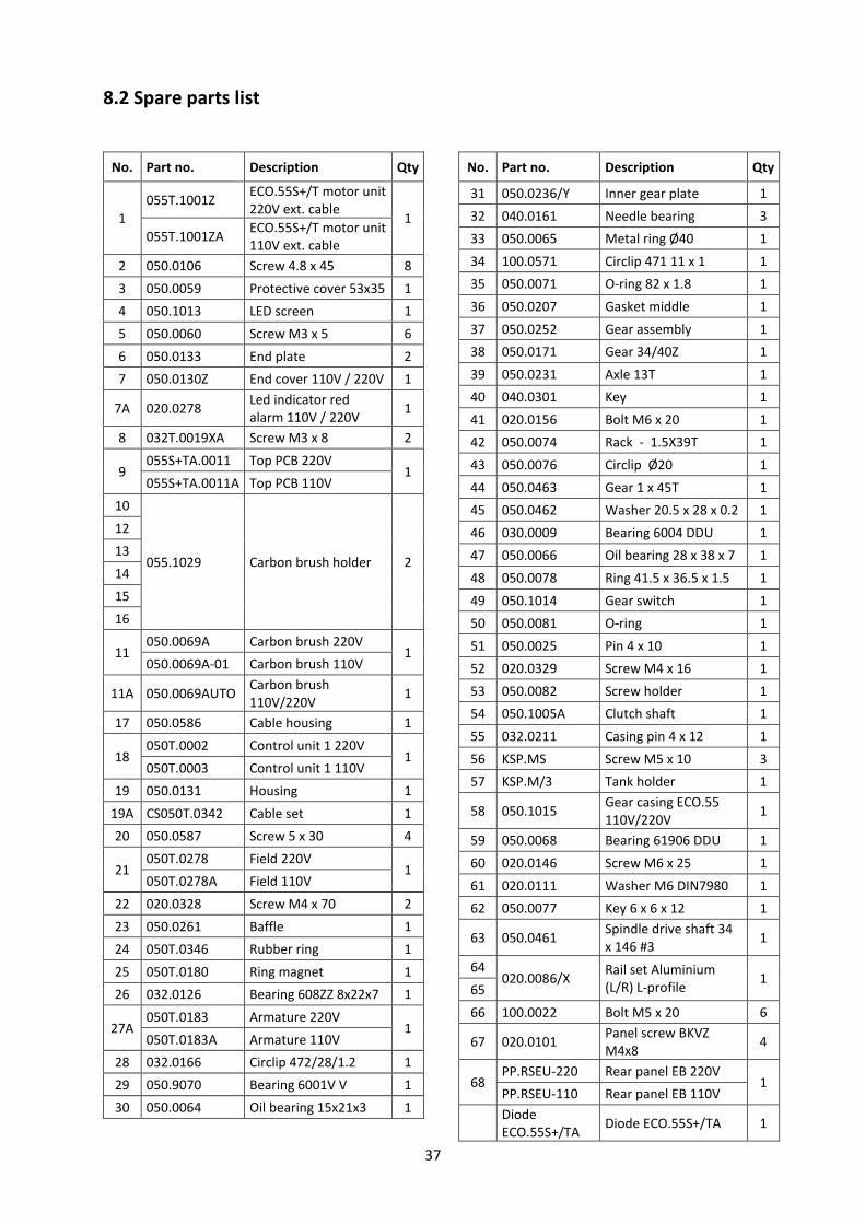
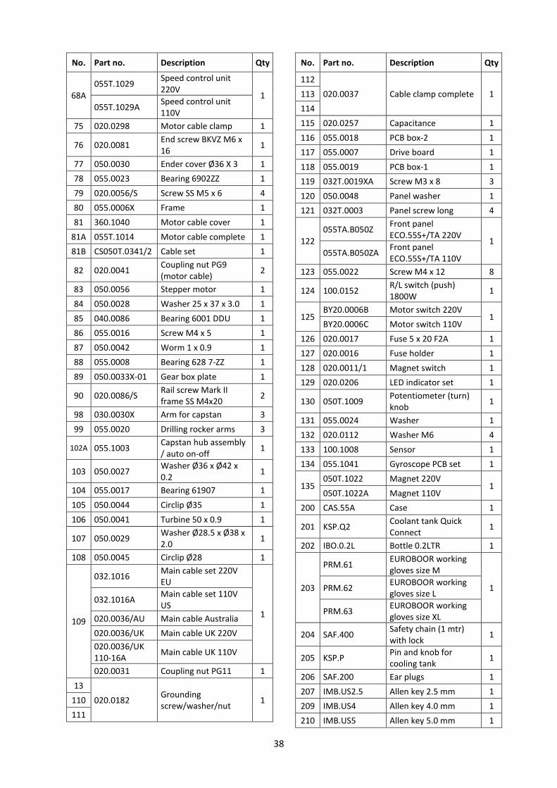
8.2 Spare parts list
No. Part no. Description Qty
1
055T.1001Z ECO.55S+/T motor unit
220V ext. cable 1
055T.1001ZA ECO.55S+/T motor unit
110V ext. cable
2 050.0106 Screw 4.8 x 45 8
3 050.0059 Protective cover 53x35 1
4 050.1013 LED screen 1
5 050.0060 Screw M3 x 5 6
6 050.0133 End plate 2
7 050.0130Z End cover 110V / 220V 1
7A 020.0278 Led indicator red
alarm 110V / 220V 1
8 032T.0019XA Screw M3 x 8 2
9 055S+TA.0011 Top PCB 220V
1 055S+TA.0011A Top PCB 110V
10
055.1029 Carbon brush holder 2
12
13
14
15
16
11 050.0069A Carbon brush 220V
1 050.0069A-01 Carbon brush 110V
11A 050.0069AUTO Carbon brush
110V/220V 1
17 050.0586 Cable housing 1
18 050T.0002 Control unit 1 220V
1 050T.0003 Control unit 1 110V
19 050.0131 Housing 1
19A CS050T.0342 Cable set 1
20 050.0587 Screw 5 x 30 4
21 050T.0278 Field 220V
1 050T.0278A Field 110V
22 020.0328 Screw M4 x 70 2
23 050.0261 Baffle 1
24 050T.0346 Rubber ring 1
25 050T.0180 Ring magnet 1
26 032.0126 Bearing 608ZZ 8x22x7 1
27A 050T.0183 Armature 220V
1 050T.0183A Armature 110V
28 032.0166 Circlip 472/28/1.2 1
29 050.9070 Bearing 6001V V 1
30 050.0064 Oil bearing 15x21x3 1
No. Part no. Description Qty
31 050.0236/Y Inner gear plate 1
32 040.0161 Needle bearing 3
33 050.0065 Metal ring Ø40 1
34 100.0571 Circlip 471 11 x 1 1
35 050.0071 O-ring 82 x 1.8 1
36 050.0207 Gasket middle 1
37 050.0252 Gear assembly 1
38 050.0171 Gear 34/40Z 1
39 050.0231 Axle 13T 1
40 040.0301 Key 1
41 020.0156 Bolt M6 x 20 1
42 050.0074 Rack - 1.5X39T 1
43 050.0076 Circlip Ø20 1
44 050.0463 Gear 1 x 45T 1
45 050.0462 Washer 20.5 x 28 x 0.2 1
46 030.0009 Bearing 6004 DDU 1
47 050.0066 Oil bearing 28 x 38 x 7 1
48 050.0078 Ring 41.5 x 36.5 x 1.5 1
49 050.1014 Gear switch 1
50 050.0081 O-ring 1
51 050.0025 Pin 4 x 10 1
52 020.0329 Screw M4 x 16 1
53 050.0082 Screw holder 1
54 050.1005A Clutch shaft 1
55 032.0211 Casing pin 4 x 12 1
56 KSP.MS Screw M5 x 10 3
57 KSP.M/3 Tank holder 1
58 050.1015 Gear casing ECO.55
110V/220V 1
59 050.0068 Bearing 61906 DDU 1
60 020.0146 Screw M6 x 25 1
61 020.0111 Washer M6 DIN7980 1
62 050.0077 Key 6 x 6 x 12 1
63 050.0461 Spindle drive shaft 34
x 146 #3 1
64 020.0086/X
Rail set Aluminium
(L/R) L-profile 1
65
66 100.0022 Bolt M5 x 20 6
67 020.0101 Panel screw BKVZ
M4x8 4
68 PP.RSEU-220 Rear panel EB 220V
1 PP.RSEU-110 Rear panel EB 110V
Diode
ECO.55S+/TA Diode ECO.55S+/TA 1
38
No. Part no. Description Qty
68A
055T.1029 Speed control unit
220V 1
055T.1029A Speed control unit
110V
75 020.0298 Motor cable clamp 1
76 020.0081 End screw BKVZ M6 x
16 1
77 050.0030 Ender cover Ø36 X 3 1
78 055.0023 Bearing 6902ZZ 1
79 020.0056/S Screw SS M5 x 6 4
80 055.0006X Frame 1
81 360.1040 Motor cable cover 1
81A 055T.1014 Motor cable complete 1
81B CS050T.0341/2 Cable set 1
82 020.0041 Coupling nut PG9
(motor cable) 2
83 050.0056 Stepper motor 1
84 050.0028 Washer 25 x 37 x 3.0 1
85 040.0086 Bearing 6001 DDU 1
86 055.0016 Screw M4 x 5 1
87 050.0042 Worm 1 x 0.9 1
88 055.0008 Bearing 628 7-ZZ 1
89 050.0033X-01 Gear box plate 1
90 020.0086/S Rail screw Mark II
frame SS M4x20 2
98 030.0030X Arm for capstan 3
99 055.0020 Drilling rocker arms 3
102A 055.1003 Capstan hub assembly
/ auto on-off 1
103 050.0027 Washer Ø36 x Ø42 x
0.2 1
104 055.0017 Bearing 61907 1
105 050.0044 Circlip Ø35 1
106 050.0041 Turbine 50 x 0.9 1
107 050.0029 Washer Ø28.5 x Ø38 x
2.0 1
108 050.0045 Circlip Ø28 1
109
032.1016 Main cable set 220V
EU
1
032.1016A Main cable set 110V
US
020.0036/AU Main cable Australia
020.0036/UK Main cable UK 220V
020.0036/UK
110-16A Main cable UK 110V
020.0031 Coupling nut PG11 1
13
020.0182 Grounding
screw/washer/nut 1 110
111
No. Part no. Description Qty
112
020.0037 Cable clamp complete 1 113
114
115 020.0257 Capacitance 1
116 055.0018 PCB box-2 1
117 055.0007 Drive board 1
118 055.0019 PCB box-1 1
119 032T.0019XA Screw M3 x 8 3
120 050.0048 Panel washer 1
121 032T.0003 Panel screw long 4
122
055TA.B050Z Front panel
ECO.55S+/TA 220V 1
055TA.B050ZA Front panel
ECO.55S+/TA 110V
123 055.0022 Screw M4 x 12 8
124 100.0152 R/L switch (push)
1800W 1
125 BY20.0006B Motor switch 220V
1 BY20.0006C Motor switch 110V
126 020.0017 Fuse 5 x 20 F2A 1
127 020.0016 Fuse holder 1
128 020.0011/1 Magnet switch 1
129 020.0206 LED indicator set 1
130 050T.1009 Potentiometer (turn)
knob 1
131 055.0024 Washer 1
132 020.0112 Washer M6 4
133 100.1008 Sensor 1
134 055.1041 Gyroscope PCB set 1
135 050T.1022 Magnet 220V
1 050T.1022A Magnet 110V
200 CAS.55A Case 1
201 KSP.Q2 Coolant tank Quick
Connect 1
202 IBO.0.2L Bottle 0.2LTR 1
203
PRM.61 EUROBOOR working
gloves size M
1 PRM.62 EUROBOOR working
gloves size L
PRM.63 EUROBOOR working
gloves size XL
204 SAF.400 Safety chain (1 mtr)
with lock 1
205 KSP.P Pin and knob for
cooling tank 1
206 SAF.200 Ear plugs 1
207 IMB.US2.5 Allen key 2.5 mm 1
209 IMB.US4 Allen key 4.0 mm 1
210 IMB.US5 Allen key 5.0 mm 1

39
No. Part no. Description Qty
211 SAF.100 Safety goggles 1
212 DRIFT3 Drift key MT3 1
213 SAF.MDMB Safety guard 1
214 020.0223 Screw M5 x 10 2
215 IMC.30/19-N Arbor MT3 - 19.05
(3/4") Weldon 1
216 TCM.10D376 Tap holder DIN376
M10 Ø7 1
217 TCM.12D376 Tap holder DIN376
M12 Ø9 1
No. Part no. Description Qty
218 TCM.14D376 Tap holder DIN376
M14 Ø11 1
219 TCM.16D376 Tap holder DIN376
M16 Ø12 1
216 TCM.3/8ANSI Tap holder ANSI 3/8" 1
217 TCM.7/16ANSI Tap holder ANSI 7/16" 1
218 TCM.1/2"ANSI Tap holder ANSI 1/2" 1
219 TCM.5/8ANSI Tap holder ANSI 5/8" 1
IBO.G101 Gear box oil IBO.G1
1LTR 1
40
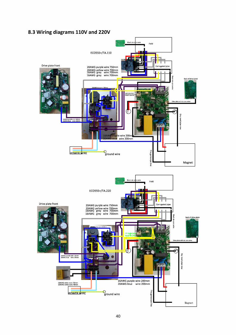
8.3 Wiring diagrams 110V and 220V

41
Serial number:
Date of purchase: / /
8.4 Warranty and service
Warranty
Euroboor B.V. warrants this magnetic drilling machine to be free of material defects and
workmanship errors under normal use for a period of 12 months after date of purchase.
This 12 month period can be extended to 24 months in total by registering the product on our
website: https://euroboor.com/support/register/
Service
To maximise the lifetime of your EUROBOOR machine always use service and parts from an official
EUROBOOR distribution channel. Whenever in need of such, always contact original point of sales or
if no longer existent the distributor of EUROBOOR products in your country.