SANDEX ECO series
56
ED ED-G SANDEX ECO series ED/ED-G ECO Series Cam technology offers environmentally friendly benefits
-
Upload
khangminh22 -
Category
Documents
-
view
0 -
download
0
Transcript of SANDEX ECO series

EDED-G
SANDEXECO series
ED/ED-GECO Series
Cam technology offers environmentally friendly benefits

1
High-performance index drive units from environmentally-friendly cam
Features● Widely used cam indexing unit, easy to control, stable drive.● High accuracy, rigidity, and long life.● Grease-sealed for virtually no maintenance.● Flat-machined housing discourages accumulation of dirt and particles.
Cam technologies are gentle to humans and the planet.
The ED/ED-G Series is a precision cam-actuated indexing drive. The output shaft rotates and stops repeatedly to produce an intermittent indexing motion.The housing is finished with electroless nickel plating to prevent rust and provide an easy to clean flat surface. The ED/ED-G Series is designed for clean-room applications and can be ordered with various shaft and flange arrangements to suit different applications.
Stand-alone cam unit ED Series
Complete with geared motorED-G Series
Roller gear cam mechanismdelivers stable motions
Indexing drives

2
developed technology
Torque Limiter
[Overload protection system/torque limiter]Sankyo's torque limiter uses a mechanical torque shutout mechanism that has a roller
(ball) and a roller pocket. This system offers accurate shut off at a preset torque, and
the torque level is easy to adjust. Also, this system meets all the requirements for
safety devices on cam units. Many, many units have been sold, which is a testament
to the highly reliable overload protection system.
TableWorkpieceJig
Indexing Drive
Geared Motor
Baskets
Product
Indexing Drive
Geared Motor
For Table/Dial Applications Conveyor applications
[Applications]

3
PRODUCT SPECIFICATIONProduct Specifications
Specifications
UnitItem
Number of stops
Input shaft speed
Indexing accuracy(one-dwell)※1
Indexing accuracy(two-dwell)※1
Repetitive accuracy
ED3.8(G) ED4.5(G) ED6(G)
2~12 2~24 2~24 2~48 2~48 2~48
±72
max.20036
±120±60
30±60±30
15±60±30
15±60±30
15±90±45
20
ED7(G) ED8(G) ED11(G)
rpm
secsecsec
※2: Specifications and dimensions are subject to change without notice. Always double check before ordering.※3: Input inertia is calculated in dwell. ※4: Figures in ( ) are for the G type.
(1N≒0.102kgf)
Output allowable axial load
UnitItem
N 490
490
2.90×10³
1.2×10‐4
1.65×10‐4
16
1.60×10³
343
343
24.5
About 3.6(7.6)
1274
1372
6.08×10³
3.45×10‐4
8.0×10‐5
33
2.74×10³
833
1078
39.2
About 7.2(11)
1372
1392
1.37×10⁴
8.22×10‐4
4.75×10‐4
34.3
4.12×10³
980
1070
58.8
About 13(19)
2156
2940
2.84×10⁴
2.33×10‐3
1.5×10‐3
63.7
8.34×10³
1470
1078
93.1
About 18(29)
3234
4116
5.29×10⁴
5.60×10‐3
2.25×10‐3
80.8
1.67×10⁴
3430
2548
245
About 33(48)
5488
6860
8.82×10⁴
1.97×10‐2
7.0×10‐3
220
2.74×10⁴
4704
4067
392
About 61(90)
NN・m/rad
N・m/rad
N・m
N・m
N
N
kg
kg・m2
kg・m2
Output allowable radial load
Output torsional rigidity
Output inertia
Output allowable bending moment
Input allowable axial load
Input torsional rigidity
Input inertia ※3
Product weight ※4
Input maximum repetitious bending force
Input maximum repetitious allowable torque
ED3.8(G)
245
245
800
5×10‐5
3.75×10‐5
3.7
3.8×10²
196
196
7.84
About 1.25
ED2.8 ED4.5(G) ED6(G) ED7(G) ED8(G) ED11(G)
980
980
2.00×10⁴
2.0×10‐3
4.5×10‐4
89
1.30×10³
343
343
24.5
About 10(14)
ME7(G)
Option
Table 3-1
Table 3-2
Table 3-3
Number of dwellsOutput type
Housing surfaceMount positionLubrication Grease
Electroless nickel platingAll position available
Flange with shaft1
ED2.8
2~10
±72
36
Shaft1 1, 2, 3 1, 2 1, 2, 3, 4 1, 2, 3, 4 1, 2, 3, 4
8~120
±144±72
36
ME7(G)
1, 2, 3, 4
Input shaft with key-way
Reamed holes(W surface)
ED3.8(G)
5TF
Maximum of two sets
ED4.5(G)
○
6TF
Maximum of two sets
ED6(G)
○
6TF
Maximum of two sets
Torque limiter installation
Timing cam+sensor installation
Overload detective sensor
ED7(G)
○
Maximum of two sets
ED8(G)
○
7, 8TF6, 7TF
Maximum of two sets
ED11(G)
○
7, 8, 11TF
Maximum of two sets
ME7(G)
○ ○ ○ ○ ○
(Contact us) ○ ○ ○ ○ ○ (Contact us)
6TF
5TC 6TC 6TC 7, 8TC6, 7TC 7, 8, 11TC 6TC
Maximum of two sets
ED2.8
4TF
Maximum of one sets
(Contact us)
4TC
Flange type
Coupling type
※1: Ask Sankyo for the indexing accuracy of 3- and 4-dwell cams.

da cb
4
MODEL CODE
ED 7 R S 1 XM3 A08 27da b f g
6 Gc h i k
Pj l ne
Product Code Example
iInput Shaft Projection
kMounting Holes
lMounting Position
nSpecial Instruction
M3 1AP X
Both T and U surface input extension and motor mounted
All surface W side GL Special Order
M3Mounting positionas shown below.
1
2
5
6
3
4
W side GLV side GLU side GLT side GLR side GLS side GL
bSize
aModel
fCam curve
gHand of Cam
dNumber of Stops(S)
eIndex Period(θ)
6
RR9
7
G
7 RED
EDR 2
08 27Centerdistance60mm
Shaft-to-shaftdistance
Indicates the model name.
Number ofstops of theIndexingDrive.
SMS-3 Curve(SANKYO Modified Sine)
Custom-madeCam Curve(Special order)
Right HandCam
1 Dwell 2 Dwell
L
L
L 2Left HandCam
ME
IndexingDrive
8 Stop SMS-3 Curve 1 Dwell Right Hand Cam270°
Indicates rotating direction of input and output shafts and number of dwells.
Double-endinput shaft with motor (side T)
GL(Ground Level)
Specify either or
cMotor
G
Geared Motor
No motor(No symbol)
Geared motor
T
S
V
W R
U
■User-specified mounting hole positions is optional.
All surface(standard)( is standard for the ED2.8, ED3.8, ME7, ED3.8G, and ME7G.)
ARSVW
MK3 With keyway (optional)
CCW
X
Standard(No Symbol)
SpecialOrder
jReamed Holes
Reamed Holes
Indicates whetherto provide reamedhole on side W.
No hole(No symbol)
P Reamed holes
hOutput
S
Standard
F
S StandardShortenshaft
L Torque limitermounted
・・ Specify either or for models ED2.8, ED3.8(G),and ME7(G)
1 Only T surface side
2 Only U surface side
3 Double-end input shaft
K1 Open-end input shaft with keyway (side T)
K2 Open-end input shaft with keyway (side U)
K3 Double-end input shaft with keyways
T
R W
SU
V
ED series ED-G series
ED series ED-G series
S L
・Specify or for models ED2.8, ED3.8, and ME7
・Models ED3.8G and ME7G are available only with
1 2 3
M3
Cam rotationperiod duringwhich theoutput movesTotal anglefor two dwellcam.( (
Include the symbol in case of special orders.X
Timing cam‐Photo switch(option) Torque limiter(option)
TC A ED6G1
aModel
bType
cNumber
dModel size
Timing cam+Photo switch
TC A 1 set1
2 set2
Indicates the size and model of ECO series mounting timing cam.
Note:● Please let us know the product code of the geared motor together with product code of the
main housing.● To find product the code of a geared motor, see each product specification page for each product.● If you want an optional torque limiter, timing cam, or sensor to be mounted on the main
housing, please let us know product code for these items, together with the product code of the main housing.
Photo microsensor
aTorque limiter
sizeb
Modeld
Type of spring
cMaximum tripping
torque
Indicates the size of the torque limiter
Flange type Indicates the maximumtripping torque
Coupling type
Flange type Heavy-dutyBelleville springs
7 TFa
Bdb
40c
Tmax400N・m(40kgf・m)
LSf
ExampleExample
TF 407 B
TFLight-duty coil springs
<Note>Models 4TF/TC to 6TF/TC aresupplied with coil springsModels 7TF/TC to 11TF/TC aresupplied with Belleville springs
A
Heavy-duty coil springsBCoil springsCTC
LS
LS
fOverload
detective sensor
Sensor
With sensor
Standard(No symbol)
※See page 46 for product codes of torque limiters.

※1:Mounting holes on sides R, S, V, and W are standard. Mounting holes on only a user-specified side is optional.
ED2.8 Dimensions
Figure ED2.8-1
(Unit : mm)
※1(24)M5×0.8, 10DP
Stop Position
Indexing period origin(0°)
S
TU
R
V
c d
b a
S
V
W
R
T
INPUT OUTPUT644
5627 27110
25 252020
80 686
44 6
φ12
φ8
28
9640 56
283833
φ15
(0.5)
(0.5)
φ10
φ8
2626
28
φ10
0 -0.015
5
0 -0.015
0 -0.015
0 -0.015
ED2.8

Timing cam‐Photo switch(option)
Code TC A 1 ED2.8
Figure ED2.8-3
φ50
Photo microsensor(OMRON)EE-SX672EE-1001(Connector)
Timing cam(Adjusted to any period 〔α〕below 180°)
α
Torque limiter mounting specifications(option)TF type TC type
A C D H J M P R
64 P.C.D.36 26 38 25 4-M4×0.74.7DP 96 04TF
Dimension Dimension
M
φD
φA
J
H
P
φC
M G
φC
φA
φD
I
H R
P
φO
Figure ED2.8-2
6
0-0.021
A C D G H M P R
64 P.C.D.40 34 5 28 4-M4×0.75DP 96 10
O
27
I
274TC +0.025 0
7
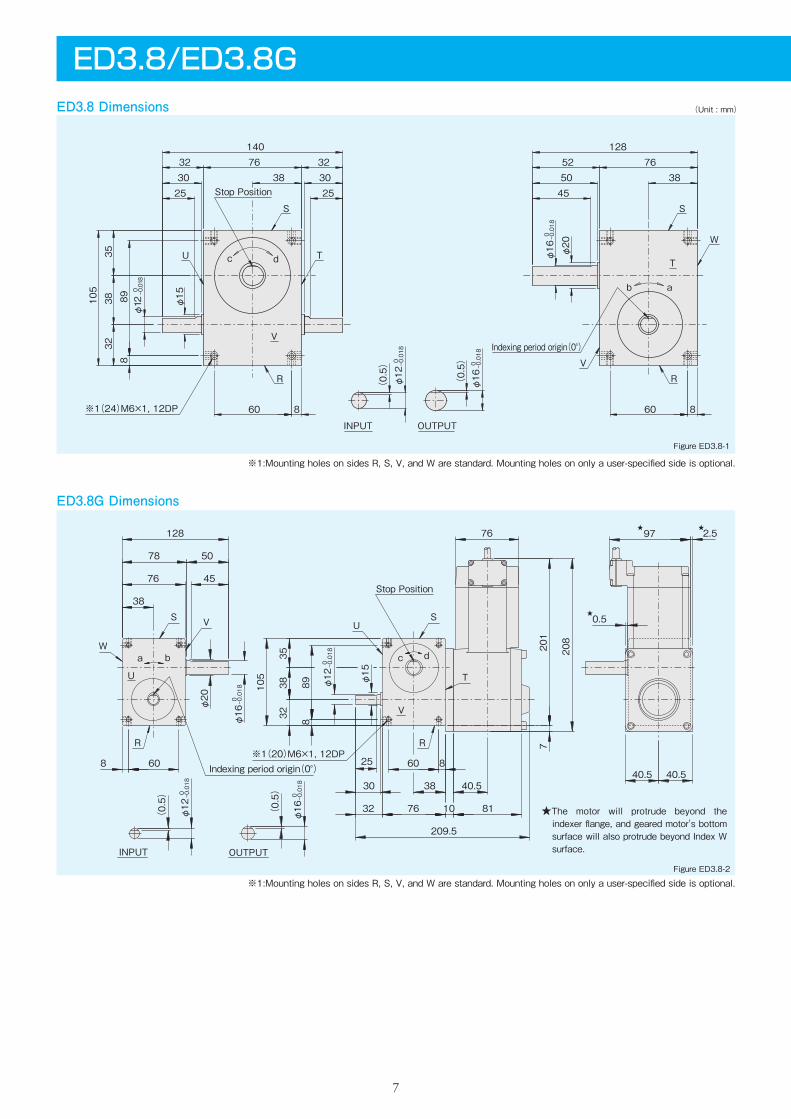
ED3.8/ED3.8GED3.8 Dimensions
ED3.8G Dimensions
(Unit : mm)
※1:Mounting holes on sides R, S, V, and W are standard. Mounting holes on only a user-specified side is optional.
Figure ED3.8-1
Figure ED3.8-2
OUTPUTINPUT
Stop Position
※1(20)M6×1, 12DPIndexing period origin(0°)
R
W
S V
U
US
R
V
T
c da b
76
209.5
40.53830
25
201
φ16
0 -0.018
(0.5)
φ12
0 -0.018
(0.5)
105
208
38
76
78 50
128
45
φ12
0 -0.018
φ15
φ16
0 -0.018
φ20
0.5
7
32 811076
3235
38
889
8 60 860
2.597
40.540.5
★
★
★
※1(24)M6×1, 12DP
Stop Position
S
TU
R
VIndexing period origin(0°)
S
W
VR
Tc d
ab
INPUT OUTPUT
76140
323230 30
2525
898
105
60 8
φ15
φ12
0 -0.018
38
1287652
385045
60 8
φ20
(0.5)
φ12
0 -0.018
φ16
0 -0.018
(0.5)
3532
38
φ16
0 -0.018
※1:Mounting holes on sides R, S, V, and W are standard. Mounting holes on only a user-specified side is optional.
★The motor will protrude beyond the indexer flange, and geared motor's bottom surface will also protrude beyond Index W surface.

8
Specifications of geared motor Table ED3.8-1
Figure ED3.8-3
Code
Waterproof motor※Voltage(V)
Motor Power(W)
ActualGear Ratio( i )
Output Shaft SpeedNM(rpm)
50Hz 60Hz
Weight(kg)
Output Allowable TorqueTR(N・m)
50Hz 60Hz
20025 0.6×10⁻⁴ 3.5
2025304050
75 605037.530
90 72 60 45 36
2.252.743.334.415.49
15 100 120 1.6710 150 180 1.08
Moment of inertiaJM(kg・m2)
GM25-20AS-ED3.8G-RGM25-25AS-ED3.8G-RGM25-30AS-ED3.8G-RGM25-40AS-ED3.8G-RGM25-50AS-ED3.8G-R
GM25-15AS-ED3.8G-RGM25-10AS-ED3.8G-R
GM25-60AS-ED3.8G-R 60 25 30 6.66
Torque limiter mounting specifications(option)
Timing cam‐Photo switch(option)
Code TC A 1 ED3.8G
Figure ED3.8-4
50φ
α
Photo microsensor(OMRON)EE-SX672EE-1001(Connector)
Timing cam(Adjusted to any period 〔α〕below 180°)
Solid line shows 1 set mounted, dashed line shows 2 sets mounted.
※ A waterproof motor is standard for model ED3.8G.
TF type TC type
A C D H J M P R
82 P.C.D.50 35 50 34 4-M4×0.75.7DP 128 05TF
DimensionA C D G H M P R
82 P.C.D.55 46 7 40 4-M4×0.77DP 128 10
O
φ36
I
395TC
Dimension
0-0.025
+0.025 0
φAφCφD
JH
P
M G
φAφCφDφO
IR H
P
M

ED4.5G Dimensions
Figure ED4.5-1
Figure ED4.5-2
9
ED4.5/ED4.5GED4.5 Dimensions (Unit : mm)
※1:Tapped mounting holes on all surfaces come automatically. Mounting holes on only a user-specified side is optional. ※2:Output shaft available to shorten to 10mm height.
※1:Tapped mounting holes on all surfaces come automatically. Mounting holes on only a user-specified side is optional. ※2:Output shaft available to shorten to 10mm height.
70 10
4545
130
40
70 10
10110
3435 90 35
34
160-0.011
0φ14 φ17
45 40 10
14050 90
845
-0.011
0φ16φ45
-0.03
0φ68
dc
Indexing period origin(0°)(Scribed line)
P.C.D.30(6)M5×0.8, 10DPStop Position
R
W
S
V
Tab
※1(24)M6×1, 12DP
S
T
U
R
V
※2
dba
c
※2
※1(20)M6×1, 12DP
Indexing period origin(0°)
V
R
U
T
S
Stop Position(6)M5×0.8, 10DP
P.C.D.30
R
W
U
S V
40.5
9035
34
45
90
140
50
8
φ68
0 -0.03
φ45
φ16
0 -0.011
40
130
φ14
0 -0.011
φ17
226.5
80 85
45
233
232
10 70
10
10 81
1070
10110
40.5 40.5
5
4045
45 φ12
(Scribed line)

10
Figure ED4.5-3
Figure ED4.5-5Figure ED4.5-4
Figure ED4.5-6Timing cam‐Photo switch(option)
Code TC A 1 ED4.5G
Input shaft with key-way(option)Reamed hole(option)
3 φ14
0 -0.0115 0-0.03
35
34
26
2-φ6 9DP+0.012 0
40±0.0220±0.1
(W surface)
110±0.02
35±0.1
Torque limiter mounting specifications(option)
φ50
Timing cam(Adjusted to any period 〔α〕below 180°)
Photo microsensor(OMRON)EE-SX672EE-1001(Connector)
α
(36)
Table ED4.5-1
20060 0.8×10⁻⁴ 3
2025304050
75 605037.530
90 72 60 45 36
5.496.968.3310.813.7
15 100 120 4.1210 150 180 2.74
60 25 30 16.7
Specifications of geared motor
CodeVoltage(V)
Motor Power(W)
ActualGear Ratio( i )
Output Shaft SpeedNM(rpm)
50Hz 60Hz
Weight(kg)
Output Allowable TorqueTR(N・m)
50Hz 60Hz
Moment of inertiaJM(kg・m2)
GM60-20AS-ED4.5GGM60-25AS-ED4.5GGM60-30AS-ED4.5GGM60-40AS-ED4.5GGM60-50AS-ED4.5G
GM60-15AS-ED4.5GGM60-10AS-ED4.5G
GM60-60AS-ED4.5G
Standard motor
Solid line shows 1 set mounted, dashed line shows 2 sets mounted.
TF type TC type
A C D H J M P R
88 P.C.D.75 60 60 48 6-M6×17DP 165 56TF
DimensionA C D G H M P R
93 P.C.D.70 50 9 52 8-M6×19DP 160 86TC
Dimension
0-0.030 +0.025
0
45°HJ
φD C
(6)
RP
φA
TL-W3MC1(OMRON)
SensorM
45°H
C
(6)
RP
G
φ95
φA
φD
MSensorTL-W3MC1(OMRON)

Indexing period origin(0°)
Stop Position(6)M6×1, 10DP
P.C.D.40
T
S
U
V
dcba
※1(20)M8×1.25, 15DP
※2
RR
W
U
VS
φ80
0 -0.03
φ55
φ20
0 -0.013 170
170
40
8
10
50120
60
90
38
270
φ16
0 -0.011
φ20
48
210
220.5
105
15
55
5555
60
12146
1286
40 9612110
12 96 48 48
φ15
(Scribed line)
ED6G Dimensions
Figure ED6-1
Figure ED6-2
※1:Tapped mounting holes on all surfaces come automatically. Mounting holes on only a user-specified side is optional. ※2:Output shaft available to shorten to 10mm height.
※1:Tapped mounting holes on all surfaces come automatically. Mounting holes on only a user-specified side is optional. ※2:Output shaft available to shorten to 10mm height.
11
ED6/ED6GED6 Dimensions (Unit : mm)
6055
55146
12
96 1286 12
-0.013
0φ20φ55
-0.03
0φ80
170
8
12060
φ20-0.011
0φ16170
1904038 55
110 4038
501040
V
U
S
T
R
Tb a
W
S
V
R
Indexing period origin(0°)
P.C.D.40
※1(24)M8×1.25, 15DP
(6)M6×1, 10DPStop Position
dc
※2
(Scribed line)

12
Timing cam‐Photo switch(option)
Figure ED6-3
Figure ED6-5
Figure ED6-6
Code TC A 1 ED6G
Input shaft with key-way(option)
3 φ16
0 -0.011
5 0-0.03
40
38
30
Figure ED6-4Reamed hole(option)
2-φ6 9DP+0.012 0
(W surface)
58±0.0229±0.1
156±0.02
48±0.1
Torque limiter mounting specifications(option)
Photo microsensor(OMRON)EE-SX672EE-1001(Connector)
Timing cam(Adjusted to any period 〔α〕below 180°)
φ50
α
Table ED6-1
20090 1.2×10⁻⁴ 42025304050
75 605037.530
90 72 60 45 36
8.3310.812.716.720.6
15 100 120 6.1710 150 180 4.12
60 25 30 24.5
Specifications of geared motor
CodeVoltage(V)
Motor Power(W)
ActualGear Ratio( i )
Output Shaft SpeedNM(rpm)
50Hz 60Hz
Weight(kg)
Output Allowable TorqueTR(N・m)
50Hz 60Hz
Moment of inertiaJM(kg・m2)
GM90-20AS-ED6GGM90-25AS-ED6GGM90-30AS-ED6GGM90-40AS-ED6GGM90-50AS-ED6G
GM90-15AS-ED6GGM90-10AS-ED6G
GM90-60AS-ED6G
Standard motor
Solid line shows 1 set mounted, dashed line shows 2 sets mounted.
TF type TC type
A C D H J M P R
88 P.C.D.75 60 60 48 6-M6×17DP 195 56TF
DimensionA C D G H M P R
93 P.C.D.70 50 9 52 8-M6×19DP 192 106TC
Dimension
0-0.030 +0.025
0
45°H
P
J
φD C φA
R
(6)
MTL-W3MC1(OMRON)
Sensor45°
H
φA
G
φ95
P
φD C
R
(6)
MTL-W3MC1(OMRON)
Sensor

ED7G Dimensions
Figure ED7-1
Figure ED7-2
※1:Tapped mounting holes on all surfaces come automatically. Mounting holes on only a user-specified side is optional. ※2:Output shaft available to shorten to 10mm height.
※1:Tapped mounting holes on all surfaces come automatically. Mounting holes on only a user-specified side is optional. ※2:Output shaft available to shorten to 10mm height.
13
ED7/ED7GED7 Dimensions (Unit : mm)
7065
60165
15
6560 130
100 15100 15
50φ25
-0.013
0φ20195
65
-0.035
0φ103
φ70
-0.013
0φ25
190
108
228
4849 130 49
48
V
(6)M6×1, 12DP
※1(24)M10×1.5, 15DP
P.C.D.50
Stop Position
Indexing period origin(0°)V
R
W
b a
T
S
R
U
S
Tdc
※2
(Scribed line)
φ25
φ20
0 -0.013
φ103 0 -0.035 φ70
φ25
0 -0.013
53.553.5
7123
288
φ25
281.5
φ115
15
100354
1304948 65
6560
10
190
50
1565
7060
195
1550
165
10010015
8
130
116
※2
(Scribed line)Indexing period origin(0°)
dc
P.C.D.50(6)M6×1, 12DP Stop Position
T
R
U
S
V
※1(20)M10×1.5, 15DP
U
S
W
V
R
a b

14
Timing cam‐Photo switch(option)
A C D H J M P R
88 P.C.D.75 60 60 48 6-M6×17DP 205 5
128 P.C.D.95 75 70 55 6-M6×19DP 215 5
6TF
7TF
DimensionA C D G H M P R
93 P.C.D.70 50 9 52 8-M6×19DP 211 19
128 P.C.D.90 70 10 65 8-M8×1.2510DP
212 7
6TC
7TC
Dimension
Code TC A 1 ED7G
Input shaft with key-way(option)
3.5
φ20
0 -0.013
6 0-0.03
49
48
40
Figure ED7-3
Figure ED7-5
Figure ED7-6
Figure ED7-4Reamed hole(option)
2-φ6 9DP+0.012 0
(W surface)
80±0.0240±0.1
181±0.02
58±0.1
Torque limiter mounting specifications(option)
Timing cam(Adjusted to any period 〔α〕below 180°)
φ66
α
Photo microsensor(OMRON)EE-SX672EE-1001(Connector)
Table ED7-1
200/220200 10.0×10⁻⁴ 8.5
1520253040
100 75605037.5
120 90 72 60 45
1723273344
14 12.5 120 144 14 12 10 150 180 11 9.2
19 24 27 37
50 30 36 55 46 60 25 30 67 55
Specifications of geared motor
Code Voltage(V)
Motor Power(W)
ActualGear Ratio( i )
Output Shaft SpeedNM(rpm)
50Hz 60Hz
Weight(kg)
Output Allowable TorqueTR(N・m)
50Hz 60Hz
Moment of inertiaJM(kg・m2)
GM200-15AS-ED7G-01GM200-20AS-ED7G-01GM200-25AS-ED7G-01GM200-30AS-ED7G-01GM200-40AS-ED7G-01
GM200-12.5AS-ED7G-01GM200-10AS-ED7G-01
GM200-50AS-ED7G-01GM200-60AS-ED7G-01
Standard motor
Solid line shows 1 set mounted, dashed line shows 2 sets mounted.
0-0.030
0-0.030
+0.025 0
+0.030 0
TF type TC type
45°J
φAC
PHR
φD
(6)
M
SensorTL-W3MC1(OMRON) 45°
φAC
G
PHR
φD
(6)
M
SensorTL-W3MC1(OMRON)

ED8G Dimensions
Figure ED8-1
Figure ED8-2
※1:Tapped mounting holes on all surfaces come automatically. Mounting holes on only a user-specified side is optional. ※2:Output shaft available to shorten to 10mm height.
※1:Tapped mounting holes on all surfaces come automatically. Mounting holes on only a user-specified side is optional. ※2:Output shaft available to shorten to 10mm height.
15
ED8/ED8GED8 Dimensions (Unit : mm)
120 20
195
2080
8075
8567 170
130 20
235
80160 6060
57
280
810
237
-0.013
0φ30φ85
-0.035
0φ118
-0.013
0φ25 φ30
5757
b a
※1(24)M10×1.5, 20DP
(6)M8×1.25, 16DPStop PositionP.C.D.60
Indexing period origin(0°)
dc
R
U
S
T
V
R
T
W
S
V
※2
(Scribed line)
φ118 0 -0.035
0 -0.013
φ85
φ30
φ25 φ30
5760 160 15
20
10 57
10653
237
13020
858
170 67
7580
16.5153.5
120
20195
80235
□137372.5
405
8058 58
φ30
355.5
dc
S
W
V
R
U
(Scribed line)
S
U
T
R
V
Stop PositionP.C.D.60
※2
Indexing period origin(0°)
※1(20)M10×1.5, 20DP
(6)M8×1.25, 16DP
a b
0 -0.013

16
Timing cam‐Photo switch(option)
A C D H J M P R
128 P.C.D.95 75 70 55 6-M6×19DP 255 5
164 P.C.D.120 100 82 65 6-M8×1.2511DP 267 5
7TF
8TF
DimensionA C D G H M P R
128 P.C.D.90 70 10 65 8-M8×1.2510DP 260 15
164 P.C.D.110 90 12 75 8-M8×1.2512DP 262 7
7TC
8TC
Dimension
Code TC A 1 ED8G
Input shaft with key-way(option)
4 φ25
0 -0.013
8 0-0.036
60
57
47
Figure ED8-3
Figure ED8-5
Figure ED8-6
Figure ED8-4Reamed hole(option)
2-φ8 12DP+0.015 0
(W surface)
90±0.0245±0.1
215±0.02
70±0.1
Torque limiter mounting specifications(option)
α
Timing cam(Adjusted to any period 〔α〕below 180°)
φ90
Photo microsensor(OMRON)EE-SX672EE-1001(Connector)
Table ED8-1
200/220400 15.0×10⁻⁴ 11.5
1520253040
100 75605037.5
120 90 72 60 45
3344556788
2712.5 120 144 27 2410 150 180 23 19
37465574
50 30 36 111 9260 25 30 133 111
Specifications of geared motor
Code Voltage(V)
Motor Power(W)
ActualGear Ratio( i )
Output Shaft SpeedNM(rpm)
50Hz 60Hz
Weight(kg)
Output Allowable TorqueTR(N・m)
50Hz 60Hz
Moment of inertiaJM(kg・m2)Standard motor
GM400-15AS-ED8G-01GM400-20AS-ED8G-01GM400-25AS-ED8G-01GM400-30AS-ED8G-01GM400-40AS-ED8G-01
GM400-12.5AS-ED8G-01GM400-10AS-ED8G-01
GM400-50AS-ED8G-01GM400-60AS-ED8G-01
Solid line shows 1 set mounted, dashed line shows 2 sets mounted.
0-0.030
0-0.035
+0.030 0
+0.035 0
TF type TC type
45°HJ
φACφD
PR
(6)
MSensorTL-W3MC1(OMRON)
45°HR
φD
G
φA
P
(6)
C
TL-W3MC1(OMRON)
SensorM

ED11G Dimensions
Figure ED11-1
Figure ED11-2
※1:Tapped mounting holes on all surfaces come automatically. Mounting holes on only a user-specified side is optional. ※2:Output shaft available to shorten to 10mm height.
※1:Tapped mounting holes on all surfaces come automatically. Mounting holes on only a user-specified side is optional. ※2:Output shaft available to shorten to 10mm height.
17
ED11/ED11GED11 Dimensions (Unit : mm)
160 20150 20
270
20110
100
310
100
586467
9519067
64
324
10020068
810
268-0.013
0φ30 φ35
-0.016
0φ35φ110
-0.04
0φ148P.C.D. 80
Indexing period origin(0°)
※1(24)M10×1.5, 20DP
(6)M10×1.5, 20DPStop Position
R
W
S
T
b a
R
T
V
U
S
dc
V
※2
(Scribed line)
686895
2520
1906764
424□156
φ148 0 -0.04
0 -0.016 0 -0.013
φ110
φ35
68
φ30 φ35
588
268200
100
20 160
310
100
110
100
20270
150
φ35
10
12462
456
476
22178
※2 (6)M10×1.5, 20DP
※1(20)M10×1.5, 20DP
Indexing period origin(0°)
Stop PositionP.C.D.80
c d
S S
T
U
R R
W
V
V
U
V
W
R
S
(Scribed line)
ba

18
A C D H J M P R
128 P.C.D.95 75 70 55 6-M6×19DP 285 5
164 P.C.D.120 100 82 65 6-M8×1.2511DP 297 5
7TF
8TF
198 P.C.D.148 120 95 75 6-M10×1.513DP 310 511TF
DimensionA C D G H M P R
128 P.C.D.90 70 10 65 8-M8×1.2510DP
292 17
164 P.C.D.110 90 12 75 8-M8×1.2512DP 294 9
7TC
8TC
198 P.C.D.130 110 16 90 8-M10×1.516DP 305 511TC
Dimension
Timing cam‐Photo switch(option)
Code TC A 1 ED11G
Input shaft with key-way(option)
5 300 -0.013
φ
10 0-0.036
67
64
54
Figure ED11-3
Figure ED11-5
Figure ED11-6
Figure ED11-4Reamed hole(option)120±0.02
60±0.1
284±0.02
87±0.1
2-φ8 12DP+0.015 0
(W surface)
Torque limiter mounting specifications(option)
α
82φ
Timing cam(Adjusted to any period 〔α〕below 180°)
Photo microsensor(OMRON)EE-SX672EE-1001(Connector)
Table ED11-1
200/220750 30.0×10⁻⁴ 21
1520253040
100 75605037.5
120 90 72 60 45
6383104124166
5212.5 120 144 52 4310 150 180 41 34
7086104138
50 30 36 208 17360 25 30 249 208
Specifications of geared motor
Code Voltage(V)
Motor Power(W)
ActualGear Ratio( i )
Output Shaft SpeedNM(rpm)
50Hz 60Hz
Weight(kg)
Output Allowable TorqueTR(N・m)
50Hz 60Hz
Moment of inertiaJM(kg・m2)
GM750-15AS-ED11G-02GM750-20AS-ED11G-02GM750-25AS-ED11G-02GM750-30AS-ED11G-02GM750-40AS-ED11G-02
GM750-12.5AS-ED11G-02GM750-10AS-ED11G-02
GM750-50AS-ED11G-02GM750-60AS-ED11G-02
Standard motor
Solid line shows 1 set mounted, dashed line shows 2 sets mounted.
0-0.030
0-0.035
0-0.035
+0.030 0
+0.035 0
+0.035 0
TF type TC type
45°
(6)
φD C φA
JHR
PSensorTL-W3MC1(OMRON)
M 45°
(6)
φD C φA
GHR
PSensorTL-W3MC1(OMRON)
M

ME7G Dimensions
Figure ME7-1
Figure ME7-2
※1:Mounting holes on sides R, S, V, and W are standard.Mounting holes on only a user-specified side is optional.
※1:Mounting holes on sides R, S, V, and W are standard.Mounting holes on only a user-specified side is optional.
ME7/ME7GME7 Dimensions (Unit : mm)
INPUT
b a
dc T
R
V
W
S
Indexing period origin(0°)
V
R
U T
S
(6)M5×0.8, 12DP
※1(24)M6×1, 12DP
Stop Position
P.C.D.50
φ12
0 -0.018
(0.5)
1065
φ60
φ35
0 -0.025
40858795
10100
φ12
0 -0.018
φ15
170
10150
333338 3840 40
200120
60
6040
70
(Scribed line)
P.C.D.50(6)M5×0.8, 12DP
V
Stop Position
R
T
U
S
c d
Indexing period origin(0°)R
a b
U
W
SV
※1(20)M6×1, 12DP
INPUT
33
95
85
40
12
0.5★
208
209
φ35
0 -0.025
φ60
φ12
0 -0.018
φ15170
76
261.5
40.560φ12
0 -0.018
(0.5)
2 8
10
99
40.5 40.510 65
4060
70
10150
40 8110120
10100
★
★Part of the motor protrudes from side W and the flange surface on the output.
19

Table ME7-1Specifications of geared motor
ActualGear Ratio( i )
Output Shaft SpeedNM(rpm)
50Hz 60Hz
Weight(kg)
Output Allowable TorqueTR(N・m)
50Hz 60Hz
20040 0.8×10⁻⁴ 3.5
2025304050
75 605037.530
90 72 60 45 36
3.534.415.297.068.82
15 100 120 2.6510 150 180 1.76
Moment of inertiaJM(kg・m2)
GM40-20AS-ME7G-RGM40-25AS-ME7G-RGM40-30AS-ME7G-RGM40-40AS-ME7G-RGM40-50AS-ME7G-R
GM40-15AS-ME7G-RGM40-10AS-ME7G-R
GM40-60AS-ME7G-R 60 25 30 10.8
Code
Waterproof motor※Voltage(V)
Motor Power(W)
Torque limiter mounting specifications(option)
Dimension Dimension
Timing cam‐Photo switch(option)
A C D H J M P R
88 P.C.D.75 60 60 48 6-M6×17DP 155
T
586TF
A C D G H M P R
95 P.C.D.70 50 9 52 8-M6×19DP 166 196TC
Code TC A 1 ME7G
Figure ME7-3
Figure ME7-4
φ50
α
Photo microsensor(OMRON)EE-SX672EE-1001(Connector)
Timing cam(Adjusted to any period 〔α〕below 180°)
Solid line shows 1 set mounted, dashed line shows 2 sets mounted.
20
0-0.030 +0.025
0
※ A waterproof motor is standard for model ME7G.
TF type TC type
45°
φD C φA
P (T)
R JH
M45°
φD C
φ95
PR H
G
φA
M

21
■Reading the torque transmission capacity table for Indexing drivesThe torque transmission capacity table gives the values for internal inertia load torque Toi and dynamic-rated output torque Top.This table was calculated based on an indexing drive that has been mounted and lubricated according to specifications and is being operated under normal conditions. Adverse operating conditions and poor maintenance can effect the transmission capacities
and life of the indexing drive.Note, when selecting models, it is important that the torque transmission capacity table be read correctly in order to make the proper selection. Always make sure to read and understand the following explana-tions carefully.
●When making sudden starts and stopsSelect a model where starting and stopping torque Td is less than the static-rated output torque Ts.
●When selecting gear reducers and motors
Selection data
First. you must obtain cam shaft torque Tc. To obtain Tc, you will need the value for cam shaft frictional torque Tx.
●For other camsPlease consult Sankyo.
●Cam Shaft Speed (N)Divide the number of indexes per minute by the number of dwells.Example) For a 2-dwell camInput shaft speed (N)= Indexes per minute 2 (number of dwells)
ED2.8~ED11 1dwell 2, 3 stop
Number of stops(S)・・・・・・・・・・・・・・・・・・・2
Index period(θ)・・・・・・・・・・・・・・・・・・・・・270degCam curve・・・・・・・・・・・・・・・・・・・・・・・・・SMS-3(Cam curve code 7)
Indexes per minute・・・20 (Input shaft speed N x number of dwells m)
20 40 60 80 100 120 200 300
C O D E
S θ(deg)Ts(N・m)
Tx(N・m)
SCF(mm)
Static-ratedOutputTorque
CamshaftFrictionalTorque
SankyoCamFollower
Dynamic-rated Output Torque Top (N・m)Internal Inertia Load Torque Toi (N・m)
Input Shaft Speed (Index/min)Numberof Stops
IndexPeriod
Reading The Torque Transmission Capacity Table [Common for both ED-G and ED models]

22
1dwell Cam Curve SMS-3(Curve Code 7)ED2.8~ED11ED2.8~ED11 1dwell 2, 3 stop
20 40 60 80 100 120 200 300
C O D E
S θ(deg)Ts(N・m)
Tx(N・m)
SCF(mm)
Static-ratedOutputTorque
CamshaftFrictionalTorque
SankyoCamFollower
Dynamic-rated Output Torque Top (N・m)Internal Inertia Load Torque Toi (N・m)
Input Shaft Speed (Index/min)Numberof Stops
IndexPeriod
Note : The Torque Transmission Capacity is the same whether the rotating direction of the input/output shafts are indicatedas right hand cams (R), or left hand cams (L). The figures in the Torque Transmission Capacity Table are indicated as R.

23
20 40 60 80 100 120 200 300
C O D E
S θ(deg)Ts(N・m)
Tx(N・m)
SCF(mm)
Static-ratedOutputTorque
CamshaftFrictionalTorque
SankyoCamFollower
Dynamic-rated Output Torque Top (N・m)Internal Inertia Load Torque Toi (N・m)
Input Shaft Speed (Index/min)Numberof Stops
IndexPeriod
Note : The Torque Transmission Capacity is the same whether the rotating direction of the input/output shafts are indicatedas right hand cams (R), or left hand cams (L). The figures in the Torque Transmission Capacity Table are indicated as R.
ED2.8~ED11 1dwell 3, 4 stop

24
20 40 60 80 100 120 200 300
C O D E
S θ(deg)Ts(N・m)
Tx(N・m)
SCF(mm)
Static-ratedOutputTorque
CamshaftFrictionalTorque
SankyoCamFollower
Dynamic-rated Output Torque Top (N・m)Internal Inertia Load Torque Toi (N・m)
Input Shaft Speed (Index/min)Numberof Stops
IndexPeriod
Note : The Torque Transmission Capacity is the same whether the rotating direction of the input/output shafts are indicatedas right hand cams (R), or left hand cams (L). The figures in the Torque Transmission Capacity Table are indicated as R.
ED2.8~ED11 1dwell 4 stop

25
20 40 60 80 100 120 200 300
C O D E
S θ(deg)Ts(N・m)
Tx(N・m)
SCF(mm)
Static-ratedOutputTorque
CamshaftFrictionalTorque
SankyoCamFollower
Dynamic-rated Output Torque Top (N・m)Internal Inertia Load Torque Toi (N・m)
Input Shaft Speed (Index/min)Numberof Stops
IndexPeriod
Note : The Torque Transmission Capacity is the same whether the rotating direction of the input/output shafts are indicatedas right hand cams (R), or left hand cams (L). The figures in the Torque Transmission Capacity Table are indicated as R.
ED2.8~ED11 1dwell 4, 5 stop

26
20 40 60 80 100 120 200 300
C O D E
S θ(deg)Ts(N・m)
Tx(N・m)
SCF(mm)
Static-ratedOutputTorque
CamshaftFrictionalTorque
SankyoCamFollower
Dynamic-rated Output Torque Top (N・m)Internal Inertia Load Torque Toi (N・m)
Input Shaft Speed (Index/min)Numberof Stops
IndexPeriod
Note : The Torque Transmission Capacity is the same whether the rotating direction of the input/output shafts are indicatedas right hand cams (R), or left hand cams (L). The figures in the Torque Transmission Capacity Table are indicated as R.
ED2.8~ED11 1dwell 5, 6 stop

27
20 40 60 80 100 120 200 300
C O D E
S θ(deg)Ts(N・m)
Tx(N・m)
SCF(mm)
Static-ratedOutputTorque
CamshaftFrictionalTorque
SankyoCamFollower
Dynamic-rated Output Torque Top (N・m)Internal Inertia Load Torque Toi (N・m)
Input Shaft Speed (Index/min)Numberof Stops
IndexPeriod
Note : The Torque Transmission Capacity is the same whether the rotating direction of the input/output shafts are indicatedas right hand cams (R), or left hand cams (L). The figures in the Torque Transmission Capacity Table are indicated as R.
ED2.8~ED11 1dwell 6, 8 stop

28
20 40 60 80 100 120 200 300
C O D E
S θ(deg)Ts(N・m)
Tx(N・m)
SCF(mm)
Static-ratedOutputTorque
CamshaftFrictionalTorque
SankyoCamFollower
Dynamic-rated Output Torque Top (N・m)Internal Inertia Load Torque Toi (N・m)
Input Shaft Speed (Index/min)Numberof Stops
IndexPeriod
Note : The Torque Transmission Capacity is the same whether the rotating direction of the input/output shafts are indicatedas right hand cams (R), or left hand cams (L). The figures in the Torque Transmission Capacity Table are indicated as R.
ED2.8~ED11 1dwell 8 stop

29
20 40 60 80 100 120 200 300
C O D E
S θ(deg)Ts(N・m)
Tx(N・m)
SCF(mm)
Static-ratedOutputTorque
CamshaftFrictionalTorque
SankyoCamFollower
Dynamic-rated Output Torque Top (N・m)Internal Inertia Load Torque Toi (N・m)
Input Shaft Speed (Index/min)Numberof Stops
IndexPeriod
Note : The Torque Transmission Capacity is the same whether the rotating direction of the input/output shafts are indicatedas right hand cams (R), or left hand cams (L). The figures in the Torque Transmission Capacity Table are indicated as R.
ED2.8~ED11 1dwell 8, 10 stop

30
20 40 60 80 100 120 200 300
C O D E
S θ(deg)Ts(N・m)
Tx(N・m)
SCF(mm)
Static-ratedOutputTorque
CamshaftFrictionalTorque
SankyoCamFollower
Dynamic-rated Output Torque Top (N・m)Internal Inertia Load Torque Toi (N・m)
Input Shaft Speed (Index/min)Numberof Stops
IndexPeriod
Note : The Torque Transmission Capacity is the same whether the rotating direction of the input/output shafts are indicatedas right hand cams (R), or left hand cams (L). The figures in the Torque Transmission Capacity Table are indicated as R.
ED2.8~ED11 1dwell 10 stop

31
20 40 60 80 100 120 200 300
C O D E
S θ(deg)Ts(N・m)
Tx(N・m)
SCF(mm)
Static-ratedOutputTorque
CamshaftFrictionalTorque
SankyoCamFollower
Dynamic-rated Output Torque Top (N・m)Internal Inertia Load Torque Toi (N・m)
Input Shaft Speed (Index/min)Numberof Stops
IndexPeriod
Note : The Torque Transmission Capacity is the same whether the rotating direction of the input/output shafts are indicatedas right hand cams (R), or left hand cams (L). The figures in the Torque Transmission Capacity Table are indicated as R.
ED2.8~ED11 1dwell 10, 12 stop

32
20 40 60 80 100 120 200 300
C O D E
S θ(deg)Ts(N・m)
Tx(N・m)
SCF(mm)
Static-ratedOutputTorque
CamshaftFrictionalTorque
SankyoCamFollower
Dynamic-rated Output Torque Top (N・m)Internal Inertia Load Torque Toi (N・m)
Input Shaft Speed (Index/min)Numberof Stops
IndexPeriod
Note : The Torque Transmission Capacity is the same whether the rotating direction of the input/output shafts are indicatedas right hand cams (R), or left hand cams (L). The figures in the Torque Transmission Capacity Table are indicated as R.
ED2.8~ED11 1dwell 12, 16 stop

33
20 40 60 80 100 120 200 300
C O D E
S θ(deg)Ts(N・m)
Tx(N・m)
SCF(mm)
Static-ratedOutputTorque
CamshaftFrictionalTorque
SankyoCamFollower
Dynamic-rated Output Torque Top (N・m)Internal Inertia Load Torque Toi (N・m)
Input Shaft Speed (Index/min)Numberof Stops
IndexPeriod
Note: A 2-dwell cam performs 2 indexes and 2 dwells per 1 turn of the input shaft. A 3-dwell cam performs 3 of each, and a 4-dwell cam performs 4 of each.The indexing angle θ given in the capacity table represents the total index period per 1 turn of the input shaft.
2, 3, 4dwell Cam Curve SMS-3(Curve Code 7)ED2.8~ED11ED2.8~ED11 2dwell 12, 16 stop

34
20 40 60 80 100 120 200 300
C O D E
S θ(deg)Ts(N・m)
Tx(N・m)
SCF(mm)
Static-ratedOutputTorque
CamshaftFrictionalTorque
SankyoCamFollower
Dynamic-rated Output Torque Top (N・m)Internal Inertia Load Torque Toi (N・m)
Input Shaft Speed (Index/min)Numberof Stops
IndexPeriod
Note: A 2-dwell cam performs 2 indexes and 2 dwells per 1 turn of the input shaft. A 3-dwell cam performs 3 of each, and a 4-dwell cam performs 4 of each.The indexing angle θ given in the capacity table represents the total index period per 1 turn of the input shaft.
ED2.8~ED11 2dwell 16, 20 stop

35
20 40 60 80 100 120 200 300
C O D E
S θ(deg)Ts(N・m)
Tx(N・m)
SCF(mm)
Static-ratedOutputTorque
CamshaftFrictionalTorque
SankyoCamFollower
Dynamic-rated Output Torque Top (N・m)Internal Inertia Load Torque Toi (N・m)
Input Shaft Speed (Index/min)Numberof Stops
IndexPeriod
Note: A 2-dwell cam performs 2 indexes and 2 dwells per 1 turn of the input shaft. A 3-dwell cam performs 3 of each, and a 4-dwell cam performs 4 of each.The indexing angle θ given in the capacity table represents the total index period per 1 turn of the input shaft.
ED2.8~ED11 2, 3 dwell 20, 24 stop

36
20 40 60 80 100 120 200 300
C O D E
S θ(deg)Ts(N・m)
Tx(N・m)
SCF(mm)
Static-ratedOutputTorque
CamshaftFrictionalTorque
SankyoCamFollower
Dynamic-rated Output Torque Top (N・m)Internal Inertia Load Torque Toi (N・m)
Input Shaft Speed (Index/min)Numberof Stops
IndexPeriod
Note: A 2-dwell cam performs 2 indexes and 2 dwells per 1 turn of the input shaft. A 3-dwell cam performs 3 of each, and a 4-dwell cam performs 4 of each.The indexing angle θ given in the capacity table represents the total index period per 1 turn of the input shaft.
ED2.8~ED11 2, 3 dwell 24, 30 stop
37
20 40 60 80 100 120 200 300
C O D E
S θ(deg)Ts(N・m)
Tx(N・m)
SCF(mm)
Static-ratedOutputTorque
CamshaftFrictionalTorque
SankyoCamFollower
Dynamic-rated Output Torque Top (N・m)Internal Inertia Load Torque Toi (N・m)
Input Shaft Speed (Index/min)Numberof Stops
IndexPeriod
Note: A 2-dwell cam performs 2 indexes and 2 dwells per 1 turn of the input shaft. A 3-dwell cam performs 3 of each, and a 4-dwell cam performs 4 of each.The indexing angle θ given in the capacity table represents the total index period per 1 turn of the input shaft.
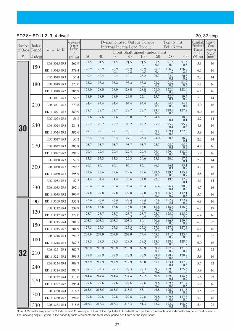
ED2.8~ED11 2, 3, 4 dwell 30, 32 stop

38
20 40 60 80 100 120 200 300
C O D E
S θ(deg)Ts(N・m)
Tx(N・m)
SCF(mm)
Static-ratedOutputTorque
CamshaftFrictionalTorque
SankyoCamFollower
Dynamic-rated Output Torque Top (N・m)Internal Inertia Load Torque Toi (N・m)
Input Shaft Speed (Index/min)Numberof Stops
IndexPeriod
Note: A 2-dwell cam performs 2 indexes and 2 dwells per 1 turn of the input shaft. A 3-dwell cam performs 3 of each, and a 4-dwell cam performs 4 of each.The indexing angle θ given in the capacity table represents the total index period per 1 turn of the input shaft.
ED2.8~ED11 2, 3, 4 dwell 32, 36, 40 stop

39
20 40 60 80 100 120 200 300
C O D E
S θ(deg)Ts(N・m)
Tx(N・m)
SCF(mm)
Static-ratedOutputTorque
CamshaftFrictionalTorque
SankyoCamFollower
Dynamic-rated Output Torque Top (N・m)Internal Inertia Load Torque Toi (N・m)
Input Shaft Speed (Index/min)Numberof Stops
IndexPeriod
Note: A 2-dwell cam performs 2 indexes and 2 dwells per 1 turn of the input shaft. A 3-dwell cam performs 3 of each, and a 4-dwell cam performs 4 of each.The indexing angle θ given in the capacity table represents the total index period per 1 turn of the input shaft.
ED2.8~ED11 3, 4 dwell 40, 48 stop

40
20 40 60 80 100 120 200 300
C O D E
S θ(deg)Ts(N・m)
Tx(N・m)
SCF(mm)
Static-ratedOutputTorque
CamshaftFrictionalTorque
SankyoCamFollower
Dynamic-rated Output Torque Top (N・m)Internal Inertia Load Torque Toi (N・m)
Input Shaft Speed (Index/min)Numberof Stops
IndexPeriod
Note: A 2-dwell cam performs 2 indexes and 2 dwells per 1 turn of the input shaft. A 3-dwell cam performs 3 of each, and a 4-dwell cam performs 4 of each.The indexing angle θ given in the capacity table represents the total index period per 1 turn of the input shaft.
ED2.8~ED11 3, 4 dwell 48 stop

41
20 40 60 80 100 120 200 300
C O D E
S θ(deg)Ts(N・m)
Tx(N・m)
SCF(mm)
Static-ratedOutputTorque
CamshaftFrictionalTorque
SankyoCamFollower
Dynamic-rated Output Torque Top (N・m)Internal Inertia Load Torque Toi (N・m)
Input Shaft Speed (Index/min)Numberof Stops
IndexPeriod
Note : The Torque Transmission Capacity is the same whether the rotating direction of the input/output shafts are indicatedas right hand cams (R), or left hand cams (L). The figures in the Torque Transmission Capacity Table are indicated as R.
1dwell Cam Curve SMS-3(Curve Code 7)ME7ME7 1dwell 8, 10, 12, 16 stop

42
20 40 60 80 100 120 200 300
C O D E
S θ(deg)Ts(N・m)
Tx(N・m)
SCF(mm)
Static-ratedOutputTorque
CamshaftFrictionalTorque
SankyoCamFollower
Dynamic-rated Output Torque Top (N・m)Internal Inertia Load Torque Toi (N・m)
Input Shaft Speed (Index/min)Numberof Stops
IndexPeriod
Note : The Torque Transmission Capacity is the same whether the rotating direction of the input/output shafts are indicatedas right hand cams (R), or left hand cams (L). The figures in the Torque Transmission Capacity Table are indicated as R.
ME7 1dwell 20, 24 stop

43
20 40 60 80 100 120 200 300
C O D E
S θ(deg)Ts(N・m)
Tx(N・m)
SCF(mm)
Static-ratedOutputTorque
CamshaftFrictionalTorque
SankyoCamFollower
Dynamic-rated Output Torque Top (N・m)Internal Inertia Load Torque Toi (N・m)
Input Shaft Speed (Index/min)Numberof Stops
IndexPeriod
Note: A 2-dwell cam performs 2 indexes and 2 dwells per 1 turn of the input shaft. A 3-dwell cam performs 3 of each, and a 4-dwell cam performs 4 of each.The indexing angle θ given in the capacity table represents the total index period per 1 turn of the input shaft.
2, 3, 4, 5dwell Cam Curve SMS-3(Curve Code 7)ME7ME7 2, 3 dwell 32, 40, 48, 60 stop

44
20 40 60 80 100 120 200 300
C O D E
S θ(deg)Ts(N・m)
Tx(N・m)
SCF(mm)
Static-ratedOutputTorque
CamshaftFrictionalTorque
SankyoCamFollower
Dynamic-rated Output Torque Top (N・m)Internal Inertia Load Torque Toi (N・m)
Input Shaft Speed (Index/min)Numberof Stops
IndexPeriod
Note: A 2-dwell cam performs 2 indexes and 2 dwells per 1 turn of the input shaft. A 3-dwell cam performs 3 of each, and a 4-dwell cam performs 4 of each.The indexing angle θ given in the capacity table represents the total index period per 1 turn of the input shaft.
ME7 3, 4, 5 dwell 72, 80, 96, 120 stop
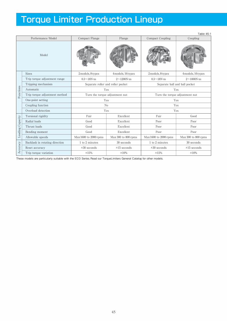
Torque Limiter Production Lineup
Performance/Model Compact Flange
2models, 8types
0.3~18N・m
4models, 16types
2~1200N・m
Fair
Good
Good
Good
Max1600 to 2000 rpms
1 to 2 minutes
±30 seconds
±15%
Excellent
Excellent
Excellent
Excellent
Max 300 to 800 rpms
30 seconds
±15 seconds
±10%
Separate roller and roller pocket
Yes
Yes
Yes
No
Turn the torque adjustment nut
2models, 8types
0.3~18N・m
4models, 16types
2~1000N・m
Fair
Poor
Poor
Poor
Max1600 to 2000 rpms
1 to 2 minutes
±30 seconds
±15%
Good
Poor
Poor
Poor
Max 300 to 800 rpms
30 seconds
±15 seconds
±10%
Separate ball and ball pocket
Yes
Yes
Yes
Yes
Turn the torque adjustment nut
Flange Compact Coupling Coupling
Model
Sizes
Trip torque adjustment range
Tripping mechanism
Automatic
Trip torque adjustment method
One-point setting
Coupling function
Overload detection
Radial loads
Thrust loads
Bending moment
Allowable speeds
Backlash in rotating direction
Reset accuracy
Trip torque variation
Functions
AccuracyLoading Capacity Torsional rigidity
Table 45-1
These models are particularly suitable with the ECO Series.Read our TorqueLimiters General Catalog for other models.
45

07 TC C 020Product Code Example
Shaft-mounting Flange (optional)
Application Examples of the TF Series Application Examples of the TC Series
Size of Torque Limiter Shaft diameter (mm)
This indicates the size of the Torque Limiter.
This indicates the diameter of the bore to machine in the flange.(See table on the right)
This flange allows you to mount the hub of the TC to a shaft.(See drawings below)
Proximity switchTorqueLimiter TF
Indexing drive
Table
Torque Limiter TF
Proximity sensor
Cam, gear, or sprocket
Indexing drive
TorqueLimiter TC
Proximity switchShaft mounting flange
Table mounting Used as an intermediate transmission element between an indexer and conveyor
Mounted on a rotating shaft to drive a cam, gear, or sprocket
Used between two shafts
Proximity sensorTorque Limiter TC
Shaft mounting flange
Figure 46-1 Figure 46-2
4TCModel Standard Shaft Diameters (mm)
5TC6TC7TC8TC11TC
12, 14, 15, 16
12, 14, 15, 1616, 20, 2520, 25, 30, 35, 4030, 35, 40, 4540, 45, 50, 55, 60
aSize of TorqueLimiter
bModel
dSpring Type
cMax Tripping Torque
This indicates the size of theTorqueLimiter.
Flange This indicates the maximum tripping torque.Coupling
Flange Belleville springsfor heavy loads
7 TFa
Bdb
40c
Tmax400N・m(40kgf・m)
LSf
Product Code Example
TF 407 B
TFBelleville springs for light loads
〈Caution〉Sizes 4TF/4TC to 6TF/6TC use coil springs.Sizes 7TF/7TC to 11TF/11TC use Belleville springs.
A
Belleville springs for heavy loadsB
Coil springsCTC
LS
LS
fOverload Detection Sensor
With sensor
With sensor
No sensor (leave blank)
46

Features・・ Roller and roller pocket torque tripping mechanism・・ Minimal backlash・・ Minimal motion loss・・ Easy to adjust trip torque setting・・ Overload detection・・ One-point setting・・ Ready for mounting tables, pulleys, etc
The Torque Limiter TF provides protection against overloads only in the rotating direction.The torque tripping mechanism is based on a roller and roller pocket. When an overload in the rotating direction occurs on the following side, the roller emerges from the roller pocket in the flange and stops the transmission of torque between the flange (on the following side) and boss (on the driving side).Torque is transmitted from the driving side to the following side via the boss and roller. This simple construction allows for a compact design that offers rigidity and accurate torque transmission, while providing reliable operation and ease of use.The flanged surface on the output allows you to directly mount a table, gear, or sprocket. This model is available in optional clean room packages.
Model
4TF-007C
4TF-010C
4TF-030C
4TF-045C
5TF-030C
5TF-060C
5TF-100C
5TF-180C
6TF-07C
6TF-1C
6TF-3C
6TF-5C
7TF-7A
7TF-12A
7TF-25B
7TF-40B
8TF-12A
8TF-20A
8TF-40B
8TF-60B
11TF-25A
11TF-35A
11TF-85B
11TF-120B
0.3~0.7
1
1.5
1.5
2
2
2
69
108
3822
7154
10290
14700
392
569
7938
10780
14700
22050
3.4
6.9
118
196
372
666
2000
1600
800
600
400
300
0.5×10⁻⁴
2.4×10⁻⁴
1.3×10⁻³
4.8×10⁻³
1.5×10⁻²
3.5×10⁻²
0.24
0.5
1.5
3.4
6.2
11.4
0.4~1.0
1.0~3.0
1.5~4.5
0.8~3.0
1.5~6.0
2.0~10.0
4.0~18.0
2~7
3~10
10~30
15~50
22~70
40~120
80~250
120~400
50~120
70~200
120~400
200~600
80~250
120~350
220~850
350~1200
ItemTrip TorqueAdjustment Range
N・m
TorqueAdjustment NutThread Pitch
mm
Max AllowableRadial Load
N
Max AllowableThrust Load
N
Max AllowableRotation Speed
r.p.m.
Inertia Moment
kg・m2
Mass
kg
Max AllowableMomentN・m
Table TF-1
Torque Limiter TF/ Flange Output
47

4TF・5TF 6TF 7~11TF
TF Series Dimensions Drawings Table TF-2
X : When an overload occurs, the overload detection panel moves X mm. This movement can be used with a detection device to control operation.(Z): Since this dimension is the reference value for the amount the torque adjustment nut protrudes when the spring height is at its maximum (free), please pay attention to any possible interference with peripheral equipment or material when installing the part. In addition, the actual (Z) dimension may fluctuate due to variations in the free spring height. *For negative dimensions, the boss side will protrude.Y : This dimension is the amount of deflection of the spring from the free height of the spring. Read the spring deflection Y from the cutoff torque of the characteristic diagram described in the "cutoff torque adjustment method" and "operation manual". Then set the cutoff torque by tightening the torque adjustment nut to the appropriate Y value in the characteristic diagram. *Since any value above the Ymax value shown in the dimension table will disable the mechanism, do not tighten the nut beyond this value.
Model
6TF-07C
6TF-1C
6TF-3C
6TF-5C7TF-7A
7TF-12A
7TF-25B
7TF-40B8TF-12A
8TF-20A
8TF-40B
8TF-60B11TF-25A
11TF-35A
11TF-85B
11TF-120B
25.0
25.5
25.0
25.530.0
31.0
30.0
31.037.5
38.5
37.5
38.542.0
43.0
42.0
43.0
88
128
164
198
88 75 M40×1.5
95
120
148
M40×1.5
M52×1.5
M72×1.5
M90×1.5
2-M5×0.8
6-M6×17DP
6-M6×19DP
6-M8×1.2511DP
6-M10×1.513DP
2-M5×0.8
2-M5×0.8
2-M5×0.8
60
75
100
120
113
138
170
58
88
108
134
60
70
82
95
5
6.6
7.6
9.6
48
55
65
75
12.5
16.5
16.5
27
30
40
52
68
102
130
160
55
75
96
1.3
2.0
1.3
2.01.6
2.5
1.6
2.51.6
2.5
1.6
2.52.0
3.0
2.0
3.0
3.9
3.2
3.9
3.21.7
0.9
1.4
0.60
-0.8
-0.7
-1.52.0
1.0
-0.5
-1.5
A B C D E F G H I J L
9.0
7.6
9.5
9.8
5TF-030C
5TF-060C
5TF-100C
5TF-180C
29.0
29.5
29.0
29.5
82 63 50 M30×1.5
4-M6×1
4-M4×0.75.7DP
35 45 5063 4.7 34 9 20
0.9
1.4
0.9
1.4
1.3
0.8
1.3
0.8
5.6
5.0
7.5
6.4
4TF-007C
4TF-010C
4TF-030C
4TF-045C
21.2
21.4
21.2
21.4
64 46 36 M20×1 46 4-M5
×0.84-M4×0.74.7DP
26 32 38 4.7 25 7 12
1.1
1.3
1.1
1.3
0.7
0.5
0.7
0.5
2.2
2.4
2.5
3.3
5.3
4.9
6.2
6.26.2
6.2
7.5
7.07.3
5.0
7.7
7.4
YmaxM N Q S U
6
4
V X (Z)〔Unit : mm〕
Figure TF-1 Figure TF-3Figure TF-2
N
M
(Max φU)
φAφBφCφD(h7)
φGφE
H(Z)
JI
VX
YL
φF
φS M
N
(Max φU)
X
IJ
L
Y
(Z)
H
φQφE
φD(h7)φCφBφA
φS
φF
G
N
(Max φU)M
φA(φB)φC
φEI
J(Z)
HXY
L
φD(h7)
φF
φS
φG
45°
45°
48

Model
4TC-007C
4TC-010C
4TC-030C
4TC-045C
5TC-030C
5TC-060C
5TC-100C
5TC-180C
6TC-06C
6TC-1C
6TC-3C
6TC-5C
7TC-6A
7TC-10A
7TC-20B
7TC-35B
8TC-12A
8TC-15A
8TC-35B
8TC-45B
11TC-20A
11TC-35A
11TC-65B
11TC-100B
0.3~0.7
1
1.5
1.5
2
2
2
1
1
1.5
1.2
1.2
1
±1.0
±1.0
±1.5
±1.8
±2.0
±2.5
0.05
0.05
0.05
0.1
0.1
0.1
2000
1600
1000
700
500
400
0.9×10⁻⁴
4.0×10⁻⁴
1.7×10⁻³
5.8×10⁻³
1.4×10⁻²
3.5×10⁻²
0.25
0.68
1.5
3.2
5.3
10.8
0.4~1.0
1.0~3.0
1.5~4.5
0.8~3.0
1.5~6.0
2.0~10.0
4.0~18.0
2~6
3~10
8~30
15~50
20~60
30~100
60~200
100~350
40~120
60~150
100~350
120~450
70~200
100~350
200~650
300~1000
ItemMax AllowableAngular Error
deg
Max AllowableClearance Error
mm
Mass
kg
Max AllowableParallelism Error
mm
Features・・ Ball and ball pocket torque tripping mechanism・・ Minimal backlash・・ Minimal motion loss・・ Easy to adjust trip torque setting・・ Overload detection・・ One-point setting・・ Absorbs misalignment (coupling function)
The Torque Limiter TC is designed to couple two shafts, such as the output of a cam indexer and an intermediate shaft, and provide protection against overloads only in the rotating direction.The torque tripping mechanism is based on a ball and ball pocket. When an overload in the rotating direction occurs on the following side, the ball emerges from the ball pocket in the hub and stops the transmission of torque between the hub (on the following side) and boss (on the driving side).The basic structure consists of a boss (on the driving side) and a hub, ball, and taper thrust ring and spring (on the following side). This simple construction allows for a compact design that offers rigidity and accurate torque transmission, while providing reliable operation and ease of use.This also allows the TC to absorb misalignment (angular error, clearance error, and parallelism error) between two shafts. This model is available in optional clean room package.
Torque Limiter TC/ Coupling Package
Table TC-1
49
TorqueAdjustment Nut Thread Pitch
mm
Trip TorqueAdjustment Range
N・m
Max AllowableRotation Speed
r.p.m.
Inertia Moment
kg・m2

4TC・5TC 7~11TC6TC
TC Series Dimensions Drawings Table TC-2〔Unit : mm〕
Figure TC-1 Figure TC-3Figure TC-2
Model
6TC-06C
6TC-1C
6TC-3C
6TC-5C7TC-6A
7TC-10A
7TC-20B
7TC-35B8TC-12A
8TC-15A
8TC-35B
8TC-45B11TC-20A
11TC-35A
11TC-65B
11TC-100B
18.5
19.0
18.5
19.030.0
31.0
30.0
31.035.0
36.0
35.0
36.041.5
43.0
41.5
43.0
93
128
164
198
95 70 M40×1.5
90
110
130
9
10
12
16
2-M5×0.8
8-M6×19DP
8-M8×1.2510DP
8-M8×1.2512DP
8-M10×1.516DP
2-M5×0.8
2-M5×0.8
2-M5×0.8
50
70
90
110
116
142
176
58
88
108
134
52
65
75
90
40
52
60
70
12.5
16.5
16.5
27
30
40
52
68
102
130
160
55
75
96
1.4
2.2
1.4
2.21.6
2.6
1.6
2.61.7
2.7
1.7
2.72.0
3.2
2.0
3.2
3.2
2.8
3.2
2.82.0
0.9
1.7
0.62.5
1.6
1.8
0.92.4
1.0
-0.1
-1.5
A B C D E F G H I J L
8.7
5.7
10.0
9.6
5TC-030C
5TC-060C
5TC-100C
5TC-180C
13.1
13.7
13.1
13.7
82 71 55 M30×1.5
4-M6×1
4-M4×0.77DP
46 45 407 39 30 9 22
0.6
1.2
0.6
1.2
0.3
-0.3
0.3
-0.3
5.4
6.5
7.6
8.0
4TC-007C
4TC-010C
4TC-030C
4TC-045C
7.6
8.0
7.6
8.0
64 52 40 M20×1 5 4-M5
×0.84-M4×0.75DP
34 32 28 27 20.5 7
15
0.7
1.1
0.7
1.1
0.6
0.2
0.6
0.2
2.7
3.0
3.3
4.0
6.4
7.1
6.4
6.210.8
5.9
6.9
5.710.8
11.2
7.4
6.7
YmaxM N Q S U
5.5
4.5
36
27
VO X (Z)
N
M
(Max φU)
φAφBφC
φO
φE
(Z)Y
IJ
GVX H
L
φD(H7)
φS
φF
N
M(Max φU)
φAφBφC
φQφE
H(Z)
JG
LX
Y
φD(H7)
φF
φS
N
M
(Max φU)
φCφB
φEφA
Y
LX
JG
H(Z)
φD(H7)
φS
φF45°
45°
50
X : When an overload occurs, the overload detection panel moves X mm. This movement can be used with a detection device to control operation.(Z): Since this dimension is the reference value for the amount the torque adjustment nut protrudes when the spring height is at its maximum (free), please pay attention to any possible interference with peripheral equipment or material when installing the part. In addition, the actual (Z) dimension may fluctuate due to variations in the free spring height. *For negative dimensions, the boss side will protrude.Y : This dimension is the amount of deflection of the spring from the free height of the spring. Read the spring deflection Y from the cutoff torque of the characteristic diagram described in the "cutoff torque adjustment method" and "operation manual". Then set the cutoff torque by tightening the torque adjustment nut to the appropriate Y value in the characteristic diagram. *Since any value above the Ymax value shown in the dimension table will disable the mechanism, do not tighten the nut beyond this value.
Sizing an ED or ED-G
Sizing Advice Figure 51‐1 When sizing a Sandex ECO Series, make sure to follow these
guidelines to ensure best performance and to prevent prema-
ture breakage.
The conditions for driving the input and the loads on the
output shaft are also important factors. Make sure you know
these conditions before sizing your indexer.
Feel free to consult with your Sankyo representative as these
calculations involve unique index-related formulas and symbols.
Sankyo can also size an indexer for you by performing the
necessary torque calculations. Use the 〈FAX Sheet〉 at the end
of this brochure for prompt service.
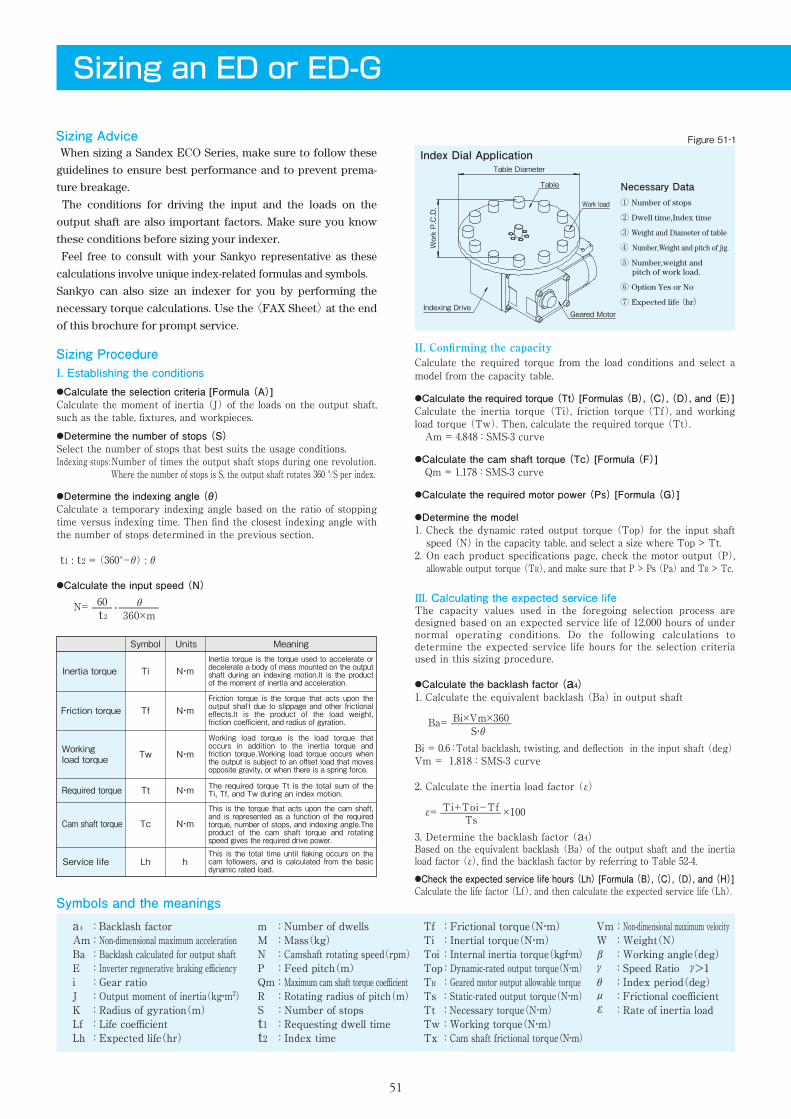
Index Dial Application
Necessary Data① Number of stops
② Dwell time,Index time
③ Weight and Diameter of table
④ Number,Weight and pitch of jig.
⑤ Number,weight and pitch of work load.
⑥ Option Yes or No
⑦ Expected life (hr)Geared Motor
Indexing Drive
Work load
Table
Work P.C.D.
Table Diameter
Sizing ProcedureI. Establishing the conditions●Calculate the selection criteria [Formula (A)]Calculate the moment of inertia (J) of the loads on the output shaft, such as the table, fixtures, and workpieces.●Determine the number of stops (S)Select the number of stops that best suits the usage conditions.Indexing stops :Number of times the output shaft stops during one revolution. Where the number of stops is S, the output shaft rotates 360 °/S per index.
●Determine the indexing angle (θ)Calculate a temporary indexing angle based on the ratio of stopping time versus indexing time. Then find the closest indexing angle with the number of stops determined in the previous section.
t1 : t2 = (360°-θ) : θ
●Calculate the input speed (N)
N= ・
II. Confirming the capacityCalculate the required torque from the load conditions and select a model from the capacity table.
●Calculate the required torque (Tt) [Formulas (B), (C), (D), and (E)]Calculate the inertia torque (Ti), friction torque (Tf), and working load torque (Tw). Then, calculate the required torque (Tt). Am = 4.848 : SMS-3 curve
●Calculate the cam shaft torque (Tc) [Formula (F)] Qm = 1.178 : SMS-3 curve
●Calculate the required motor power (Ps) [Formula (G)]
●Determine the model1. Check the dynamic rated output torque (Top) for the input shaft speed (N) in the capacity table, and select a size where Top > Tt.2. On each product specifications page, check the motor output (P), allowable output torque (TR), and make sure that P > Ps (Pa) and TR > Tc.
t260
360×mθ
S・θBi×Vm×360
TsTi+Toi-Tf
Symbol
Ti
Tf
Tw
Tt
Tc
Lh
N・m
N・m
N・m
N・m
N・m
h
Inertia torque
Friction torque
Working load torque
Required torque
Cam shaft torque
Service life
Units MeaningInertia torque is the torque used to accelerate or decelerate a body of mass mounted on the output shaft during an indexing motion.It is the product of the moment of inertia and acceleration.
Friction torque is the torque that acts upon the output shaft due to slippage and other frictional effects.It is the product of the load weight, friction coefficient, and radius of gyration.
This is the torque that acts upon the cam shaft, and is represented as a function of the required torque, number of stops, and indexing angle.The product of the cam shaft torque and rotating speed gives the required drive power.
This is the total time until flaking occurs on the cam followers, and is calculated from the basic dynamic rated load.
The required torque Tt is the total sum of the Ti, Tf, and Tw during an index motion.
Working load torque is the load torque that occurs in addition to the inertia torque and friction torque.Working load torque occurs when the output is subject to an offset load that moves opposite gravity, or when there is a spring force.
51
Symbols and the meanings
a4 : Backlash factorAm : Non-dimensional maximum accelerationBa : Backlash calculated for output shaftE : Inverter regenerative braking efficiencyi : Gear ratioJ : Output moment of inertia(kg・m2)K : Radius of gyration(m)Lf : Life coefficientLh : Expected life(hr)
m : Number of dwellsM : Mass(kg)N : Camshaft rotating speed(rpm)P : Feed pitch(m)Qm : Maximum cam shaft torque coefficientR : Rotating radius of pitch(m)S : Number of stopst1 : Requesting dwell timet2 : Index time
Tf : Frictional torque(N・m)Ti : Inertial torque(N・m)Toi : Internal inertia torque(kgf・m)Top : Dynamic-rated output torque(N・m)TR : Geared motor output allowable torqueTs : Static-rated output torque(N・m)Tt : Necessary torque(N・m)Tw : Working torque(N・m)Tx : Cam shaft frictional torque(N・m)
Vm : Non-dimensional maximum velocityW : Weight(N)β : Working angle(deg)γ : Speed Ratio γ>1θ : Index period(deg)μ : Frictional coefficientε : Rate of inertia load
III. Calculating the expected service lifeThe capacity values used in the foregoing selection process are designed based on an expected service life of 12,000 hours of under normal operating conditions. Do the following calculations to determine the expected service life hours for the selection criteria used in this sizing procedure.
●Calculate the backlash factor (a4)1. Calculate the equivalent backlash (Ba) in output shaft
Ba=
Bi = 0.6 :Total backlash, twisting, and deflection in the input shaft (deg)Vm = 1.818 : SMS-3 curve
2. Calculate the inertia load factor (ε)
ε= ×100
3. Determine the backlash factor (a4)Based on the equivalent backlash (Ba) of the output shaft and the inertia load factor (ε), find the backlash factor by referring to Table 52-4.●Check the expected service life hours (Lh) [Formula (B), (C), (D), and (H)]Calculate the life factor (Lf), and then calculate the expected service life (Lh).

Formulas
Radius of gyration K
Table 52‐1
Table 52‐2
J=MK2 (kg・m2)
Rotary Motion Linear Motion
J= M( )2 (kg・m2)2πS・P
Ti=226.2Am (N・m)
Tf=W ・ μ ・ R (N・m)
Tw=R ・ F ・ cos β (N・m)
Tt=Ti+Tf+Tw (N・m)
S・(θ/m)2J・N2 Ti=5.73Am (N・m)
(θ/m)2M・S・P2・N2
Tc=500Qm (Tt+Toi)+Tx (N・m)S・θ1
Tf= (N・m)2πW・μ・S・P
Tw= cosβ (N・m)2πF・S・P
Ps= (kW)9550Tc・N
Pa= Ps (kW)21
Lf= Lh= 12000Lf10/3 (hr) where, a4(Ti+Toi)+Tf+TwTop
Backlash factor a4
Life factor(Lf) and expected life(Lh) Table 52‐3
Table 52‐4
-5-3-2-1012345681012152025303540
1.001.001.001.001.001.021.031.041.051.051.061.071.071.081.091.101.121.121.131.14
0.05 0.1 0.2 0.3 0.4 0.5 0.6 0.8 1.0 1.2 1.5 2.0 2.5 3.0 4.0 5.0 6.0 8.0 10.0
1.001.001.001.001.021.041.061.081.091.111.121.141.151.171.181.211.241.261.271.29
1.001.001.001.001.061.091.121.151.181.211.241.271.301.331.361.421.481.511.541.57
1.001.001.001.041.081.121.161.201.241.281.321.361.401.441.481.561.641.681.721.76
1.001.001.001.051.101.151.201.251.301.351.401.451.501.551.601.701.801.851.901.95
1.001.001.001.061.121.181.241.301.361.421.481.541.601.661.721.841.962.022.082.14
1.001.001.001.081.161.241.321.401.481.561.641.721.801.881.962.122.282.362.442.52
1.001.001.001.091.181.271.361.451.541.631.721.811.901.992.082.262.442.532.622.71
1.001.001.001.101.191.301.401.501.601.701.801.902.002.102.202.402.602.702.802.90
1.001.001.011.111.221.331.441.551.661.771.881.992.102.212.322.542.762.872.983.09
1.001.001.021.131.231.361.481.601.721.841.962.082.202.322.442.682.923.043.163.28
1.001.001.061.171.291.421.561.701.841.982.122.262.402.542.682.963.243.383.523.66
1.001.001.071.191.331.481.641.801.962.122.282.442.602.762.923.243.563.723.884.04
1.001.001.081.201.341.511.681.852.022.192.362.532.702.873.043.383.723.894.064.23
1.001.011.101.261.421.601.802.002.202.402.602.803.003.203.403.804.204.404.604.80
1.001.011.121.281.461.661.882.102.322.542.762.983.203.423.644.084.524.744.965.18
1.001.011.151.301.491.721.962.202.442.682.923.163.403.643.884.364.845.085.325.56
1.001.031.171.361.591.842.122.402.682.963.243.523.804.084.364.925.485.766.046.32
1.001.051.191.421.701.962.282.602.923.243.563.884.204.524.845.486.126.446.767.08
Baε
ε: Rate of inertia load Ba: Backlash calculated for output shaft
K2 2
K2
r122r12+r22
3a2+b2
2r12
2r12+r22
3a2+b2+R2 +R2 +R2
aa b b
a b ba
R
r1 r1r2
R r1r2
R r1
Motor power for an average load [where Ti > (Tf + Tw)]
Lh(hr)
20003000400050006000700080009000100001200014000
Lf
0.584 0.660 0.719 0.769 0.812 0.851 0.885 0.917 0.947 1.00 1.05
Lh(hr)
1600018000200002200024000260002800030000350004000045000
Lf
1.09 1.13 1.17 1.20 1.23 1.26 1.29 1.32 1.38 1.44 1.49
Lh(hr)
5000055000600006500070000750008000090000100000110000120000
Lf
1.53 1.58 1.62 1.66 1.70 1.73 1.77 1.83 1.89 1.94 2.00
52
(A)Moment of inertia J
(B)Inertia torque Ti
(C)Frictional torque Tf
(E)Necessary torque Tt
(F)Cam shaft torque Tc
(H)Expected life Lh
(G)Peak motor power Ps
(D)Working torque Tw

Model Sizing Form for the SANDEX ECO(ED/ED-G) seriesCustomer’s Company, Department
Name
Application
TEL
FAXAddress
Contact at Sankyo
Attention: Date
Our contactperson:
ED-2021/03E-S
Index Dial Application Table diameter : D1
Table weight : M1
Jig P.C.D. : D2
Weight per tool : M2
Weight per work : M3
Number of tool : n2
Work P.C.D. : D3
[mm]
[kg]
[kg]
[kg]Number of work : n3
[mm]
[mm]
Conveyor Application Feed pitch : P
Weight of chain with attachment : M1
Weight of tool : M2
Weight of work : M3
Number of sproket : n4
Sproket diameter : D
Weight per sproket : M4
[mm]
[kg]
[kg]
Coefficient of friction : μ
[mm]
[kg]
[kg]
Geared Motor
MEMO
Torque Limiter Timing Cam - Sensor□ Yes □ No □ Yes □ No □ Yes □ No
Number of stops Working time : t1[sec]
Index time : t2[sec]
Table Diameter[D1]
Work P.C.D.[D3]
Tool P.C.D.[D2] Table
WorkTool
Indexing Drive
Geared Motor
Tool
Work
Indexing Drive
Geared Motor
Feed pitch[P]
Sprocket diameter[D]
53

54
Global network
Mon-Fri AM8:30-12:00 PM13:00-17:30 UTC + 09:00 (JST) (Except public holidays and company holidays) Contact us
■Taiwan Sales Office No.21, Ln.152, Jianxing Rd., Sanhe Vil., Daya Dist., Taichung City 42876, Taiwan (R.O.C.)Phone: +886-(0)4-2359-4048 Fax: +886-(0)4-2359-4720Email: [email protected]
■Headquarters (International Sales Division)
3-37-3 Tabatashinmachi, Kita-ku, Tokyo, Japan 114-8538Phone: +81-(0)3-3800-3330Fax: +81-(0)3-3800-3380 Email: [email protected]: http://www.sankyo-seisakusho.co.jp
Rodax Vietnam Co., Ltd.
Singapore
Sankyo Works(Thailand)Co., Ltd.
Taiwan
Sankyo America Inc.
Sankyo Korea Co., Ltd.
Thailand
India
Italy
Hangzhou Sankyo Machinery Co., Ltd.
Sankyo China Trading Co., Ltd.
Sankyo Shizuoka Seisakusho Co.Sankyo Seisakusho Co.
Group CompaniesSankyo America Inc.10655 State Route 47 Sidney, Ohio, 45365 U.S.A.Phone: +1-(0)937-498-4901 Fax: +1-(0)937-498-9403Email: [email protected]
Sankyo Korea Co., Ltd.1449-48 Seobu-ro, Gwonseon-gu, Suwon-si, Gyeonggi-do, 16643 KoreaPhone: +82-(0)31-895-5991 Fax: +82-(0)31-895-6607Email: [email protected]
Sankyo China Trading Co., Ltd.[Shanghai Sales Office]Room 1103, Block B, No.391 Guiping Road, Shanghai 200233 ChinaPhone: +86-(0)21-5445-2813 Fax: +86-(0)21-5445-2340Email: [email protected]
Rodax Vietnam Co., Ltd.Plot No. M1, Thang Long Industrial Park IiDi Su, My Hao, Hung Yen, Viet NamPhone: +84-(0)221-3-589701 Fax: +84-(0)221-3-589708
Sankyo Works (Thailand) Co., Ltd.9/31 Moo 5, Phaholyotin Road, Klongnueng, Klong Luang, Patumthani 12120 ThailandPhone: +66-(0)2-516-5355 Fax: +66-(0)2-068-0931Email: [email protected]
Hangzhou Sankyo Machinery Co., Ltd.No.2518 Jiang Dong 2 Road, Hangzhou Jiang Dong Industrial Park,Xiaoshan Zone, Hangzhou, Zhejiang, ChinaPhone: +86-(0)571-8283-3311 Fax: +86-(0)571-8283-1133
[Shenzhen Sales Office]Unit 19j, Tower B, Neo Building, No.6009 Shennan Avenue, Futian District, Shenzhen ChinaPhone: +86-(0)755-8230-0270 Fax: +86-(0)755-8236-4605
[Tianjin Sales Office]Room 1905, Pengzhanfeiwo Building A, Crossing Yale Road Yaolin Road, Xiqing District, Tianjin 300380 ChinaPhone: +86-(0)22-2312-1005 Fax: +86-(0)22-2312-1007
[Guangzhou Sales Office]Room 913, Xing Pu Buliding, No.12 Guan Hong Road,Guangzhou Economic Development Zone, Huang Pu, Guang Zhou 510670 ChinaPhone: +86-(0)20-8985-1846 Fax: +86-(0)20-8225-7346
[Wuhan Sales Office]Room 2301, Taihe Square, No.134 Wusheng Road, Wuhan, Hubei Province ChinaPhone: +86-(0)27-8568-5818 Fax: +86-(0)27-8568-2818
Global Sales OfficesProduction Facilities
Headquarters
International Distributors

ED-2021/03E(DT)
For further information, questions, or inquires, please contact us by e-mail or visit our website.*Specifications and dimensions are subject to change whithout notice. Consult Sankyo sales before ordering.
http://www.sankyo-seisakusho.co.jp